JP5956586B2 - Suture fixing device and method of using the same - Google Patents
Suture fixing device and method of using the same Download PDFInfo
- Publication number
- JP5956586B2 JP5956586B2 JP2014534549A JP2014534549A JP5956586B2 JP 5956586 B2 JP5956586 B2 JP 5956586B2 JP 2014534549 A JP2014534549 A JP 2014534549A JP 2014534549 A JP2014534549 A JP 2014534549A JP 5956586 B2 JP5956586 B2 JP 5956586B2
- Authority
- JP
- Japan
- Prior art keywords
- suture
- bone
- fixture
- fixation system
- recess
- Prior art date
- Legal status (The legal status is an assumption and is not a legal conclusion. Google has not performed a legal analysis and makes no representation as to the accuracy of the status listed.)
- Active
Links
- 0 CCCCC(*)(CC)[C@@](C)C[N+]([O-])=O Chemical compound CCCCC(*)(CC)[C@@](C)C[N+]([O-])=O 0.000 description 1
Images


Classifications
-
- A—HUMAN NECESSITIES
- A61—MEDICAL OR VETERINARY SCIENCE; HYGIENE
- A61B—DIAGNOSIS; SURGERY; IDENTIFICATION
- A61B17/00—Surgical instruments, devices or methods, e.g. tourniquets
- A61B17/04—Surgical instruments, devices or methods, e.g. tourniquets for suturing wounds; Holders or packages for needles or suture materials
- A61B17/0401—Suture anchors, buttons or pledgets, i.e. means for attaching sutures to bone, cartilage or soft tissue; Instruments for applying or removing suture anchors
- A61B2017/0409—Instruments for applying suture anchors
-
- A—HUMAN NECESSITIES
- A61—MEDICAL OR VETERINARY SCIENCE; HYGIENE
- A61B—DIAGNOSIS; SURGERY; IDENTIFICATION
- A61B17/00—Surgical instruments, devices or methods, e.g. tourniquets
- A61B17/04—Surgical instruments, devices or methods, e.g. tourniquets for suturing wounds; Holders or packages for needles or suture materials
- A61B17/0401—Suture anchors, buttons or pledgets, i.e. means for attaching sutures to bone, cartilage or soft tissue; Instruments for applying or removing suture anchors
- A61B2017/0412—Suture anchors, buttons or pledgets, i.e. means for attaching sutures to bone, cartilage or soft tissue; Instruments for applying or removing suture anchors having anchoring barbs or pins extending outwardly from suture anchor body
-
- A—HUMAN NECESSITIES
- A61—MEDICAL OR VETERINARY SCIENCE; HYGIENE
- A61B—DIAGNOSIS; SURGERY; IDENTIFICATION
- A61B17/00—Surgical instruments, devices or methods, e.g. tourniquets
- A61B17/04—Surgical instruments, devices or methods, e.g. tourniquets for suturing wounds; Holders or packages for needles or suture materials
- A61B17/0401—Suture anchors, buttons or pledgets, i.e. means for attaching sutures to bone, cartilage or soft tissue; Instruments for applying or removing suture anchors
- A61B2017/0414—Suture anchors, buttons or pledgets, i.e. means for attaching sutures to bone, cartilage or soft tissue; Instruments for applying or removing suture anchors having a suture-receiving opening, e.g. lateral opening
-
- A—HUMAN NECESSITIES
- A61—MEDICAL OR VETERINARY SCIENCE; HYGIENE
- A61B—DIAGNOSIS; SURGERY; IDENTIFICATION
- A61B17/00—Surgical instruments, devices or methods, e.g. tourniquets
- A61B17/04—Surgical instruments, devices or methods, e.g. tourniquets for suturing wounds; Holders or packages for needles or suture materials
- A61B17/0401—Suture anchors, buttons or pledgets, i.e. means for attaching sutures to bone, cartilage or soft tissue; Instruments for applying or removing suture anchors
- A61B2017/0438—Suture anchors, buttons or pledgets, i.e. means for attaching sutures to bone, cartilage or soft tissue; Instruments for applying or removing suture anchors slotted, i.e. having a longitudinal slot for enhancing their elasticity
-
- A—HUMAN NECESSITIES
- A61—MEDICAL OR VETERINARY SCIENCE; HYGIENE
- A61B—DIAGNOSIS; SURGERY; IDENTIFICATION
- A61B17/00—Surgical instruments, devices or methods, e.g. tourniquets
- A61B17/04—Surgical instruments, devices or methods, e.g. tourniquets for suturing wounds; Holders or packages for needles or suture materials
- A61B17/0401—Suture anchors, buttons or pledgets, i.e. means for attaching sutures to bone, cartilage or soft tissue; Instruments for applying or removing suture anchors
- A61B2017/0445—Suture anchors, buttons or pledgets, i.e. means for attaching sutures to bone, cartilage or soft tissue; Instruments for applying or removing suture anchors cannulated, e.g. with a longitudinal through-hole for passage of an instrument
-
- A—HUMAN NECESSITIES
- A61—MEDICAL OR VETERINARY SCIENCE; HYGIENE
- A61B—DIAGNOSIS; SURGERY; IDENTIFICATION
- A61B17/00—Surgical instruments, devices or methods, e.g. tourniquets
- A61B17/04—Surgical instruments, devices or methods, e.g. tourniquets for suturing wounds; Holders or packages for needles or suture materials
- A61B17/0401—Suture anchors, buttons or pledgets, i.e. means for attaching sutures to bone, cartilage or soft tissue; Instruments for applying or removing suture anchors
- A61B2017/0446—Means for attaching and blocking the suture in the suture anchor
- A61B2017/0458—Longitudinal through hole, e.g. suture blocked by a distal suture knot
-
- A—HUMAN NECESSITIES
- A61—MEDICAL OR VETERINARY SCIENCE; HYGIENE
- A61B—DIAGNOSIS; SURGERY; IDENTIFICATION
- A61B17/00—Surgical instruments, devices or methods, e.g. tourniquets
- A61B17/04—Surgical instruments, devices or methods, e.g. tourniquets for suturing wounds; Holders or packages for needles or suture materials
- A61B17/0401—Suture anchors, buttons or pledgets, i.e. means for attaching sutures to bone, cartilage or soft tissue; Instruments for applying or removing suture anchors
- A61B2017/0446—Means for attaching and blocking the suture in the suture anchor
- A61B2017/0459—Multiple holes in the anchor through which the suture extends and locking the suture when tension is applied
-
- A—HUMAN NECESSITIES
- A61—MEDICAL OR VETERINARY SCIENCE; HYGIENE
- A61B—DIAGNOSIS; SURGERY; IDENTIFICATION
- A61B17/00—Surgical instruments, devices or methods, e.g. tourniquets
- A61B17/04—Surgical instruments, devices or methods, e.g. tourniquets for suturing wounds; Holders or packages for needles or suture materials
- A61B2017/0496—Surgical instruments, devices or methods, e.g. tourniquets for suturing wounds; Holders or packages for needles or suture materials for tensioning sutures
Description
本発明は縫合糸固定具およびその使用方法に関する。 The present invention relates to a suture anchor and a method of using the same.
今日、縫合糸を固定することを目的とし、縫合糸が軟組織を通過して骨に至る設計の縫合糸固定具が多数市場に出ている。好適な方法は、組織を固定具に留めるために縫合糸に結び目を作る必要がない固定具を使用することが多い。この転換は、より簡単で時間のかからない手順を可能にした。さらに、結び目は固定具の不具合のよくある原因であることが証明されている。 Today, there are a number of suture fasteners on the market that are designed to secure a suture and that the suture passes through soft tissue to reach the bone. The preferred method often uses a fastener that does not require a knot in the suture to hold the tissue to the fastener. This conversion enabled a simpler and less time consuming procedure. Furthermore, knots have proven to be a common cause of fixture failure.
しかしながら、結び目なしの固定具には課題が多数ある。多くの固定具は配置中に縫合糸の張力を変更することができ、外科医は最終的な設置ステップ中にどの程度の張力が加わるかを推定しなければならない。この結果、骨に対する組織の張力が小さすぎたり大きすぎたりする可能性がある。固定具の植込み後に縫合糸に張力を加えることのできる固定具は多くの部品を伴うため複雑になり、高価で信頼性のない固定具になるおそれがある。この種の固定具はユーザ支援の張力装置を備えることがあり、過剰に張力がかかった縫合糸が固定具を骨から外へ引き出す可能性がある。 However, there are a number of problems with fasteners without knots. Many fasteners can change the tension of the suture during deployment, and the surgeon must estimate how much tension is applied during the final installation step. As a result, tissue tension on the bone may be too small or too large. A fixture that can apply tension to the suture after implantation of the fixture is complex because it involves many parts and can be an expensive and unreliable fixture. This type of fixture may include a user-assisted tension device, and an over-tensioned suture may pull the fixture out of the bone.
固定具の植込み前に縫合糸に張力を加えることのできるその他の固定具は、縫合糸に不均等な張力をかけるおそれがある。さらに、固定具の多くは3つ以上の縫合糸端部を利用することができず、不所望の金属部品を有する。 Other fasteners that can apply tension to the suture prior to implantation of the fastener can place unequal tension on the suture. In addition, many fasteners cannot utilize more than two suture ends and have undesirable metal parts.
縫合糸を骨に留めるのに使用される固定具は他にも多数ある。上述したように、結び目なしの固定具設計は、結び目の不具合がないために好適である。
Arthrex社のPUSHLOCK(商標)固定具は2部形式の固定具である。固定具の先端には、縫合糸脚部を挿入するヒモ穴が形成される。この先端は骨に開けた穴の底部に配置される。この時点で、外科医は縫合糸の張力を調節することによって、組織を骨の表面に近づけることができる。固定具の後部を穴に引き込むときに穴と係合することなく縫合糸に一度に張力がかかるため、張力が正確でない場合がある。いったん固定具の後部が穴に入ると、縫合糸の張力は調節することができない。
There are many other fasteners used to secure a suture to a bone. As mentioned above, a knotless fixture design is preferred because there are no knot defects.
The Arthrex PUSHLOCK ™ fixture is a two-part fixture. A strap hole for inserting the suture leg is formed at the tip of the fixing tool. This tip is placed at the bottom of a hole in the bone. At this point, the surgeon can bring the tissue closer to the bone surface by adjusting the tension of the suture. The tension may be inaccurate because the suture is tensioned at once without engaging the hole when the rear of the fixture is pulled into the hole. Once the back of the fastener enters the hole, the suture tension cannot be adjusted.
Smith and Nephew社はKINSA(商標)縫合糸固定具を販売している。この固定具は、骨に予め開けた穴に引き込まれるPEEK(ポリエーテルエーテルケトン)製の結び目なしの設計である。固定具は、固定具の本体内で一方向に摺動する結び目で結ばれた縫合糸が予め挿入されており、固定具を配置した後に外科医が張力を調節することができる。このため、組織を既に通過している縫合糸を利用できず、組織の単純な縫合しか提供できない。 Smith and Nephew sells KINSA ™ suture anchors. This fixture is a knotless design made of PEEK (polyetheretherketone) that is drawn into a pre-drilled hole in the bone. The fastener is pre-inserted with a suture tied with a knot that slides in one direction within the body of the fixture, and the surgeon can adjust the tension after the fixture is placed. For this reason, sutures that have already passed through the tissue cannot be used, and only a simple suture of the tissue can be provided.
Conmed Linvatec社のPOPLOK(商標)は別の結び目なしの固定具である。この2片のポリマー固定具は、縫合糸を固定具に係止する前に縫合糸を個々に受け入れ、張力をかけることができる。しかしながら、固定具は落下の可能性のある複数片を有する。 Conmed Livatec's POPLOK ™ is another knotless fixture. The two pieces of polymer fasteners can individually receive and tension the sutures prior to locking the sutures to the fasteners. However, the fixture has multiple pieces that can fall.
Mitek社のVERSALOK(商標)も結び目なしの固定具である。この2片のポリマーおよび金属固定具は、縫合糸を固定具に係止する前に縫合糸を個々に受け入れ、張力をかけることができる。固定具を形成する複数部分を有し、内部部材は金属製である。 Mitek's VERSALOK ™ is also a knotless fixture. The two pieces of polymer and metal fasteners can receive and tension the sutures individually before locking the sutures to the fasteners. It has a plurality of parts forming a fixture, and the internal member is made of metal.
Mitek社のCUFFLINK(商標)結び目なし縫合糸およびCUFFLINK SP(商標)結び目なし縫合糸(金属先端での自己穿孔)固定具はPEEK製で、金属を使用しない一体型ポリマー設計を使用して製造されている。この設計により、固定具は3つ以上の縫合糸端部を受け入れることができ、最終的な固定具配置の前にこれらの端部のそれぞれに張力をかけ、あるいは張力を解放することで、外科医は各縫合糸で所望の張力を実現することができる。また、固定具は縫合糸を伴い、または伴わず組織(腱、靱帯、異種移植片、同種移植片、またはコラーゲン足場)を受け入れて、組織−骨を直接修復することもできる。金属先端バージョンでは、パイロット穴を必要とせずに骨に直接固定具を打ち込むことができる。最終的に、この設計は配置中に固定具に力を加える金属配置装置を組み込むことによって、固定具の破損を低減する。 Mitek's CUFFLINK ™ knotless suture and CUFFLINK SP ™ knotless suture (self-drilling at the metal tip) fasteners are made of PEEK and manufactured using an integral polymer design that does not use metal. ing. This design allows the fastener to accept more than two suture ends and allows the surgeon to either tension or release each of these ends prior to final fastener placement. Can achieve the desired tension with each suture. The anchor can also receive tissue (tendons, ligaments, xenografts, allografts, or collagen scaffolds) with or without sutures to directly repair tissue-bone. In the metal tip version, the fixture can be driven directly into the bone without the need for a pilot hole. Ultimately, this design reduces fixture breakage by incorporating a metal placement device that applies force to the fixture during deployment.
本発明は、骨に縫合糸または組織を留めることを目的とした縫合糸または組織固定具を提供する。外科医が骨と密着させて組織を固定する必要がある、回旋腱板、SLAP(上方関節唇損傷)、バンカート損傷修復、または関節窩縁までの唇組織の再建など、軟組織−骨修復手順は多数存在する。骨の表面は粗いことが多く、組織が密着させられると、身体の治癒反応が組織と骨を融合させる。次に、この縫合糸は所望の位置で軟組織を通過し、結び目を作ることによって固定具に留められる。他には、縫合糸をまず組織を通過させ、次に結び目なしで固定具と縫合糸を骨に固定する方法がある。 The present invention provides a suture or tissue anchor intended to secure a suture or tissue to a bone. Soft tissue-bone repair procedures, such as rotator cuff, SLAP (upper joint lip injury), Bankart injury repair, or lip tissue reconstruction to the glenoid margin, where the surgeon needs to fix the tissue in close contact with the bone There are many. The surface of the bone is often rough, and when the tissue is brought into close contact, the body's healing reaction fuses the tissue and bone. The suture is then passed through the soft tissue at the desired location and secured to the fastener by tying a knot. Another method is to first pass the suture through the tissue and then secure the fastener and suture to the bone without a knot.
より具体的には、本発明の一側面では、縫合糸穴が横方向に貫通して延在する本体と、本体の長さの一部に沿って延在し、本体の外面からの所定深さを有する縫合糸凹部と、縫合糸凹部の近位端に配置される縫合糸挟み斜面とを含む組織を骨に留めるための固定システムが提供される。縫合糸挟み斜面は、遠位端で該所定深さとほぼ等しい深さを有し、縫合糸挟み斜面の近位端での深さがほぼゼロになるように近位方向において外方に傾斜する。 More specifically, in one aspect of the present invention, the suture hole extends in a lateral direction and extends along a part of the length of the main body, and has a predetermined depth from the outer surface of the main body. A fixation system is provided for securing tissue to a bone that includes a suture recess having a thickness and a suture pinch bevel disposed at a proximal end of the suture recess. The suture pinch bevel has a depth approximately equal to the predetermined depth at the distal end and is inclined outward in the proximal direction so that the depth at the proximal end of the suture pin bevel is substantially zero. .
好ましくは、植込物は周囲の骨内に植込物を留める外面特徴をさらに備える。これらの外面特徴は骨かかりを備える。本体の外面と隣接骨との間で縫合糸または組織を締め付ける縫合糸かかりが、近位端で本体の外面に配置される。固定具の最初の配置中に縫合糸を最適に摺動させるため骨を縫合糸の遠位に移動させる骨配置タブが、植込物本体の遠位部分に配置される。 Preferably, the implant further comprises an external feature that secures the implant within the surrounding bone. These exterior features provide a stake. A suture bar that clamps the suture or tissue between the outer surface of the body and the adjacent bone is disposed at the outer surface of the body at the proximal end. A bone placement tab is disposed in the distal portion of the implant body that moves the bone distal to the suture for optimal sliding of the suture during initial placement of the fastener.
内部空隙が固定具の本体に設けられ、この空隙は固定具の本体の近位端に挿入装置を収容する開口部を有する。固定具の本体は縫合糸挟み斜面に隣接する縫合糸止めをさらに備える。 An internal cavity is provided in the body of the fixture, the cavity having an opening for receiving the insertion device at the proximal end of the body of the fastener. The body of the fixture further includes a suture clasp adjacent the suture pinching ramp.
固定システムは、固定具を骨に配置するために固定具の本体と係合可能な挿入部材をさらに備える。挿入部材は、近位握り部分と握り部分の遠位端に接続される挿入管とを備える。縫合糸滑車ロッドは、挿入管の遠位端から拡張および後退可能である。一対の止め受けが滑車ロッドの遠位端に設けられ、対の止め受け間に間隙が設けられる。滑車ロッドを挿入管に対して後退および拡張させる回転可能なノブが握り部分に配置される。ノブ解放スライドが握りに配置される。 The fixation system further comprises an insertion member that is engageable with the body of the fixture to place the fixture on the bone. The insertion member comprises a proximal grip portion and an insertion tube connected to the distal end of the grip portion. The suture pulley rod can be expanded and retracted from the distal end of the insertion tube. A pair of stop receptacles are provided at the distal end of the pulley rod, and a gap is provided between the pair of stop receptacles. A rotatable knob is disposed at the grip portion to retract and expand the pulley rod relative to the insertion tube. A knob release slide is placed on the grip.
本発明の別の側面では、本体を有する植込み型固定具を、挿入装置を用いて遠位方向に所望の骨部位の所定の最初の配置深さまで動かすステップと、本体の外面に配置される凹部と、縫合糸凹部の近位で同じく本体の外面に配置される挟み斜面とを用いて、固定具の本体と隣接骨との間に配置される縫合糸または組織に圧力を印加するステップとを備える、骨に軟組織を留める方法が開示される。固定具の本体と隣接骨との間に配置される縫合糸または組織の自由端に所望のレベルまで張力をかけるステップと、挿入装置の一部を備える挿入管に近位方向に滑車ロッドを引き込むステップと、植込み型固定具を骨部位へとさらに遠位に動かして固定具を最終的に配置するステップと、が追加される。縫合糸または組織は、植込物本体の外面のかかりと隣接骨との間、および固定具の本体の両側の止めの間に挟まれ、適所に係止される。さらに、本発明の方法ステップは、固定具の本体から滑車ロッドを引き抜き挿入装置を解放するステップと、自由縫合糸端部を切断して手順を完了させるステップとを含む。 In another aspect of the invention, moving an implantable fixture having a body distally to a predetermined initial placement depth of a desired bone site using an insertion device, and a recess disposed on the outer surface of the body Applying pressure to the suture or tissue disposed between the body of the fastener and the adjacent bone using a pinch bevel disposed proximate the suture recess and also on the outer surface of the body. A method for securing soft tissue to bone is disclosed. Tensioning the free end of the suture or tissue placed between the body of the fixture and the adjacent bone to a desired level, and retracting the pulley rod proximally into the insertion tube with a portion of the insertion device And a step of moving the implantable fastener further distally to the bone site to finally place the fastener. The suture or tissue is sandwiched between the barbs on the outer surface of the implant body and the adjacent bone and between stops on both sides of the body of the anchor and locked in place. Further, the method steps of the present invention include withdrawing the pulley rod from the body of the fixture to release the insertion device and cutting the free suture end to complete the procedure.
本発明のさらに別の側面では、固定具の本体を骨に配置するために固定具の本体と係合可能な挿入部材を備える、組織を骨に留める固定システムが提供される。挿入部材は近位握り部分と、握り部分の遠位端に接続される挿入管と、挿入管の遠位端から拡張および後退可能な縫合糸滑車ロッドとを備える。一対の止め受けが滑車ロッドの遠位端に配置され、一対の止め受け間に間隙が設けられる。滑車ロッドを挿入管に対して後退および拡張させる回転可能なノブが握り部分に設けられ、ノブ解放スライドが握りに配置される。 In yet another aspect of the present invention, a fixation system for securing tissue to bone is provided that includes an insertion member engageable with the body of the fastener to place the body of the fastener into the bone. The insertion member includes a proximal gripping portion, an insertion tube connected to the distal end of the gripping portion, and a suture pulley rod that is expandable and retractable from the distal end of the insertion tube. A pair of retaining receptacles are disposed at the distal end of the pulley rod, and a gap is provided between the pair of retaining receptacles. A rotatable knob for retracting and expanding the pulley rod relative to the insertion tube is provided on the grip portion, and a knob release slide is disposed on the grip.
本発明と追加の特徴および利点は、添付図面と併せて以下の説明を参照することによって最も適切に理解することができる。 The invention and additional features and advantages can best be understood by referring to the following description in conjunction with the accompanying drawings.
本明細書に開示される本発明のシステムおよび方法は、配置前に縫合糸または組織の張力を調節でき、配置されるときに縫合糸または組織(および、結果として捕獲された組織)の張力を変えず、縫合糸または組織を固定する結び目を必要とせず、複数の縫合糸端部を受け入れる、挿入が容易な縫合糸固定具を備える。 The systems and methods of the present invention disclosed herein can adjust the tension of the suture or tissue prior to deployment, and can adjust the tension of the suture or tissue (and the resulting captured tissue) when deployed. An easy-to-insert suture anchor that does not change, does not require a knot to secure a suture or tissue, and accepts a plurality of suture ends.
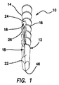
図面をより具体的に参照すると、図1〜6には本発明の原理により構成される縫合糸固定具10が示されている。固定具10は、複数の近位縫合糸かかり14と骨かかり16とを有する本体12を備える。本体12の外面の一部は縫合糸凹部18を備える。内部空隙20(図3)は後述の縫合糸滑車ロッドを収容するために設けられる。固定具の本体12の遠位端は骨配置タブ22を含む。
Referring more specifically to the drawings, FIGS. 1-6 illustrate a
縫合糸凹部18内には、縫合糸挟み斜面24、縫合糸止め26、および本体の対向側面に対して開放した本体12の幅方向に横切って延在する縫合糸穴28が配置される。
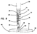
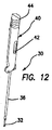
次に図7〜13を参照し、固定具10の挿入システム30を説明する。挿入システムまたは挿入装置30は、縫合糸滑車ロッド32(図7)、滑車ロッド32(図7)の遠位端の縫合糸止め受け34、挿入管36を備える。実施形態によっては、任意の金属遠位端38(図9)を採用することができる。
In the
Next, the
挿入システム30の握り部分40を図10〜13に示す。握り部分40はノブ解放スライド42と近位ノブ44を備える。
固定具10は、革新的な機能にとって重要な特徴を多数有する。たとえば、縫合糸かかり14は、植込物が配置されるときに周囲の骨に対して縫合糸を挟む。残りのかかりは縫合糸かかり14の遠位の骨かかり16であり、最初の配置と最終の配置との間で骨を係合する役割を果たす。縫合糸凹部18は本体12の外面の残りの部分に対する凹形状により、最初の配置中に縫合糸を固定具の本体と隣接骨間で摺動させることができる。縫合糸滑車ロッド32の内部空隙20のおかげで、最初の配置中、金属縫合糸滑車ロッド32が固定具を支持することができる。骨配置タブ22は骨を縫合糸から遠位に移動させて、最初の配置中、縫合糸を最適に摺動させる。
A gripping
The
縫合糸挟み斜面24は、縫合糸に個々に張力をかける間、張力を維持するのを助ける。斜面は近位方向において外方に傾斜するように構成されるため、遠位端は縫合糸凹部18とほぼ同じ程度の深さであり、近位端は植込物本体12の外面とほぼ同じ深さ、すなわちほぼゼロの深さである。縫合糸止め26は縫合糸を挟んで、構造物の縫合糸引出力を増大させる。縫合糸穴28により、1つまたはそれ以上の縫合糸端部を植込物に配置することができる。上述したように、各縫合糸端部は個別に張力をかけることができる。固定具10の先端46は図9に示されるように閉鎖して図示されているが、任意の金属端38を固定具10に追加して、パイロット穴を必要とせずに固定具を直接骨に挿入することができる。
The
挿入システム30も、出願人の本発明のシステムの革新的な機能に寄与するいくつかの重要な特徴を備える。具体的には、縫合糸滑車ロッド32は、最初の配置段階で、縫合糸が縫合糸止め26に入るのを防ぐことによって、縫合糸を縫合糸穴28内で自由に移動させるができる。また、滑車ロッド32は最初の配置中、固定具の本体12の遠位端46まで延在させることによって固定具10の力を増大させる。挿入管36と滑車ロッド32は、最初の配置中、層入力を槌から固定具に伝達する。近位ノブ44が回転すると、最初の配置段階と最終の配置段階との間で、滑車ロッド32を後退させる機構が始動される。ノブ解放スライド42はノブ44を解放して、最終配置後に挿入装置30の取り外しを可能にする。縫合糸止め受け34は最終配置中の縫合糸止め26の設定間隙を維持する。
The
残りの図14〜32を参照し、本発明のシステムを使用して固定具10を骨48に配置する方法を説明する。
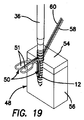
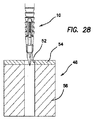
固定具10を適切な骨部位に配置するため、まず縫合糸50を、修復を要する軟組織(図示せず)に通す。たとえば図19を参照すると、縫合糸50の縫合糸ループ51は通常、骨48に隣接する軟組織によって占められているが、明瞭化のため組織は図示していない。もしくは、縫合糸50を使用せずに、軟組織自体を所望の骨部位48に直接固定してもよく、この場合、組織はこの説明に記載される縫合糸と同じように操作される。このため、便宜上「縫合糸」という用語を本明細書全体を通じて使用しているが、その用語は軟組織自体など類似の機能上の特徴を有するその他の媒体も含むように十分幅広く考えるべきである。皮質骨層54を通り海綿骨層56までパイロット穴52(図9および28)が接着部位(骨48)に開けられる。状況によっては、任意の金属遠位端38を採用してもよく(図9)、その場合、パイロット穴を開けるステップは不要である。次に、図14および15に示されるように、縫合糸が縫合糸穴28を通して直接またはスネアとともに供給される。1つまたはそれ以上の縫合糸端部58、60(図15)をヒモ穴28に通してもよい。
With reference to the remaining FIGS. 14-32, a method of placing the
In order to place the
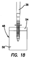
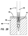
固定具10と装着される挿入装置30とが図14および15に示されるように所望の骨部位に配置されると、固定具10の最初の配置を行うことができる。なお、図16、17、28は図14および15と同じステップを示すが、明瞭化のために縫合糸50を取り除いている。この最初の配置を開始させるため、槌が握り部分40の近位端に対して打ち込まれ、図18および19、さらに図20、21、29に示されるように、固定具10を最初の配置位置から遠位に追いやり、ここでも縫合糸は明瞭化のために取り除いてある。この時点で、縫合糸凹部18は固定具の本体12の外面と隣接骨表面との間に配置される縫合糸または組織50、および縫合糸挟み斜面24に対して圧力を印加するように動作している。この圧力は縫合糸50にかかる張力を維持させる。
Once the
自由縫合糸端部58、60は、縫合糸滑車ロッド32を回って縫合糸ループ51内で組織を固定具および修復部位とその周囲の骨48に対して近づけるようにそれぞれ張力をかけることができる。縫合糸に過剰な張力がかかれば、プローブを使用して組織側の縫合糸を緩めることができる。
The free suture ends 58, 60 can each be tensioned around the
いったん所望の張力が達成されれば、縫合糸滑車ロッド32は、さらなる回転が防止されるまで握り部分40のネジ式近位ノブ44を回転させることによって近位で挿入管36に引き込まれる。管36がノブ44の回転によって後退されれば、縫合糸止め26の間隙が露出する。この時点で、縫合糸止め受け34は縫合糸止め26の両側に配置される。後退した滑車ロッドの位置は図26および27に示され、この位置は最終挿入ステップ前に必要とされる位置である。上述したように、縫合糸止め26が露出され縫合糸止め受け34によって開放されるため、最終挿入中に縫合糸を適切な位置に引き込むことができる。
Once the desired tension is achieved, the
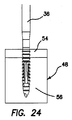
この時点で、最終配置ステップが図22および23、さらには図24、25、30に示されるように開始され、縫合糸50は明瞭化のため取り除いてある。縫合糸止め26の間隙は縫合糸止め受け34によって維持されており、挿入装置握り40が再度打ち込まれて、図30に示されるように固定具10が骨表面の下方に位置するまで挿入管36に挿入力を印加する。縫合糸50は骨表面から均等な距離で保持されるため、張力印加後および最終配置後、縫合糸50の張力は維持される。追加の張力が必要な場合、固定具を骨内にさらに深く打ち込んで、縫合糸端部を引くことによって張力を増大させる。
At this point, the final placement step has begun as shown in FIGS. 22 and 23, as well as FIGS. 24, 25 and 30, and the
この時点で縫合糸50は図23に示されるように縫合糸かかり14と固定具の組織側の骨との間に挟まれている。また、固定具の本体12の両側で縫合糸止め26の間にも挟まれている。最後に、自由縫合糸端部58、60は縫合糸かかり14と固定具の組織側に対向する骨に挟まれる。
At this time, the
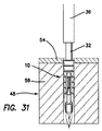
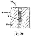
ここで縫合糸滑車ロッド32は図31に示されるように固定具の本体12から引き抜き、ノブ解放スライド42を始動してネジ式ノブ44を自由に回転させることによって挿入装置30を解放してもよい。その後、ノブ44は、挿入装置が植込物から解放されるまで回転させられる。この時点で、自由縫合糸端部を図32に示されるように切断して、修復を終了させることができる。
The
本発明の例示の実施形態を図示し説明したが、本明細書で使用される用語はすべて制限的ではなく説明的であり、以下の特許請求の範囲によってのみ限定される本発明の精神と範囲から逸脱せずに当業者によって多数の変更、修正、置換が可能であることを理解すべきである。 While exemplary embodiments of the invention have been illustrated and described, all terminology used herein is descriptive rather than restrictive, and the spirit and scope of the invention is limited only by the following claims. It should be understood that many variations, modifications, and substitutions can be made by those skilled in the art without departing from the invention.
Claims (11)
Applications Claiming Priority (3)
| Application Number | Priority Date | Filing Date | Title |
|---|---|---|---|
| US201161542688P | 2011-10-03 | 2011-10-03 | |
| US61/542,688 | 2011-10-03 | ||
| PCT/US2012/000493 WO2013052128A1 (en) | 2011-10-03 | 2012-10-03 | Suture anchors and methods of use |
Publications (3)
| Publication Number | Publication Date |
|---|---|
| JP2015501172A JP2015501172A (en) | 2015-01-15 |
| JP2015501172A5 JP2015501172A5 (en) | 2015-11-26 |
| JP5956586B2 true JP5956586B2 (en) | 2016-07-27 |
Family
ID=48044059
Family Applications (1)
| Application Number | Title | Priority Date | Filing Date |
|---|---|---|---|
| JP2014534549A Active JP5956586B2 (en) | 2011-10-03 | 2012-10-03 | Suture fixing device and method of using the same |
Country Status (5)
| Country | Link |
|---|---|
| US (3) | US9402617B2 (en) |
| EP (2) | EP3305210B1 (en) |
| JP (1) | JP5956586B2 (en) |
| IN (1) | IN2014CN03247A (en) |
| WO (1) | WO2013052128A1 (en) |
Families Citing this family (35)
| Publication number | Priority date | Publication date | Assignee | Title |
|---|---|---|---|---|
| US10426456B2 (en) | 2009-07-17 | 2019-10-01 | Pivot Medical, Inc. | Method and apparatus for re-attaching the labrum to the acetabulum, including the provision and use of a novel suture anchor system |
| US11246585B2 (en) | 2009-07-17 | 2022-02-15 | Stryker Puerto Rico Limited | Method and apparatus for attaching tissue to bone, including the provision and use of a novel knotless suture anchor system |
| US9149268B2 (en) | 2009-07-17 | 2015-10-06 | Pivot Medical, Inc. | Method and apparatus for attaching tissue to bone, including the provision and use of a novel knotless suture anchor system |
| US9179905B2 (en) | 2009-07-17 | 2015-11-10 | Pivot Medical, Inc. | Method and apparatus for re-attaching the labrum to the acetabulum, including the provision and use of a novel suture anchor system |
| US10058319B2 (en) | 2009-07-17 | 2018-08-28 | Pivot Medical, Inc. | Method and apparatus for attaching tissue to bone, including the provision and use of a novel knotless suture anchor system, including a novel locking element |
| US10238379B2 (en) | 2009-07-17 | 2019-03-26 | Pivot Medical, Inc. | Method and apparatus for attaching tissue to bone, including the provision and use of a novel knotless suture anchor system |
| US10136884B2 (en) | 2009-07-17 | 2018-11-27 | Pivot Medical, Inc. | Method and apparatus for attaching tissue to bone, including the provision and use of a novel knotless suture anchor system, including a retractable sheath |
| US11197663B2 (en) | 2009-07-17 | 2021-12-14 | Stryker Puerto Rico Limited | Method and apparatus for attaching tissue to bone, including the provision and use of a novel knotless suture anchor system |
| AU2012275207B2 (en) | 2011-06-29 | 2016-10-06 | Stryker Puerto Rico Limited | Method and apparatus for re-attaching the labrum to the acetabulum, including the provision and use of a novel suture anchor system |
| US9402617B2 (en) | 2011-10-03 | 2016-08-02 | Cayenne Medical, Inc. | Suture anchors and methods of use |
| US9782165B2 (en) | 2011-11-11 | 2017-10-10 | VentureMD Innovations, LLC | Transosseous attachment |
| US10548585B2 (en) | 2011-11-16 | 2020-02-04 | VentureMD Innovations, LLC | Soft tissue attachment |
| US10470756B2 (en) | 2011-11-16 | 2019-11-12 | VentureMD Innovations, LLC | Suture anchor and method |
| US10136883B2 (en) | 2011-11-16 | 2018-11-27 | VentureMD Innovations, LLC | Method of anchoring a suture |
| US10675014B2 (en) | 2011-11-16 | 2020-06-09 | Crossroads Extremity Systems, Llc | Knotless soft tissue attachment |
| WO2013114347A1 (en) * | 2012-02-05 | 2013-08-08 | Implament Pty Limited | Suture anchor with cleat formation to secure suture thread |
| US20150272567A1 (en) | 2012-08-03 | 2015-10-01 | Stabilynx, Inc. | Devices, systems, and methods for attaching soft tissue to bone tissue |
| US9687221B2 (en) | 2013-02-13 | 2017-06-27 | Venture MD Innovations, LLC | Method of anchoring a suture |
| WO2014176270A1 (en) | 2013-04-22 | 2014-10-30 | Pivot Medical, Inc. | Method and apparatus for attaching tissue to bone |
| US9936940B2 (en) | 2013-06-07 | 2018-04-10 | Biomet Sports Medicine, Llc | Method and apparatus for coupling soft tissue to bone |
| AU2014362199B2 (en) | 2013-12-12 | 2019-07-11 | Stryker Puerto Rico Limited | Method and apparatus for attaching tissue to bone, including the provision and use of a novel knotless suture anchor system |
| US10779811B2 (en) | 2014-12-11 | 2020-09-22 | Smith & Nephew, Inc. | Bone anchor having improved fixation strength |
| WO2016111856A1 (en) * | 2015-01-06 | 2016-07-14 | Smith & Nephew, Inc. | Knotless suture or tissue anchor and method |
| EP3291743B1 (en) | 2015-04-24 | 2020-01-15 | Biomet Sports Medicine, LLC | Anchoring system for securing a suture to a pre-drilled bore |
| US10154868B2 (en) | 2015-07-17 | 2018-12-18 | Kator, Llc | Transosseous method |
| US10820918B2 (en) | 2015-07-17 | 2020-11-03 | Crossroads Extremity Systems, Llc | Transosseous guide and method |
| US9962174B2 (en) | 2015-07-17 | 2018-05-08 | Kator, Llc | Transosseous method |
| US10143462B2 (en) | 2015-08-04 | 2018-12-04 | Kator, Llc | Transosseous suture anchor method |
| US9526494B1 (en) | 2015-12-18 | 2016-12-27 | Valeris Medical, Llc | Bone anchor delivery system device and method |
| USD816843S1 (en) * | 2017-06-07 | 2018-05-01 | Alevio, Llc | Orthopedic implant |
| CA3069688C (en) * | 2017-07-14 | 2022-06-21 | Biomet Sports Medicine, Llc | Anchoring system and method for securing a suture to a pre-drilled bore |
| US10786236B2 (en) * | 2017-08-04 | 2020-09-29 | Tigon Medical | Knotless anchor |
| US20190059875A1 (en) * | 2017-08-22 | 2019-02-28 | Tigon Medical | Cannulated anchor system and method |
| US11045184B2 (en) | 2018-03-09 | 2021-06-29 | Coloplast A/S | Tissue anchor, tissue anchor assembly, and tissue anchor system |
| US11013507B2 (en) | 2018-11-30 | 2021-05-25 | Oxford Performance Materials, Inc. | Suture anchors and methods of use |
Family Cites Families (34)
| Publication number | Priority date | Publication date | Assignee | Title |
|---|---|---|---|---|
| US5258016A (en) | 1990-07-13 | 1993-11-02 | American Cyanamid Company | Suture anchor and driver assembly |
| US5733307A (en) | 1996-09-17 | 1998-03-31 | Amei Technologies, Inc. | Bone anchor having a suture trough |
| US5957924A (en) | 1997-05-22 | 1999-09-28 | Bionx Implants Oy | Installation tool for suture anchor |
| US5980558A (en) * | 1997-09-30 | 1999-11-09 | Biomet Inc. | Suture anchor system |
| US6045574A (en) | 1999-04-01 | 2000-04-04 | Thal; Raymond | Sleeve and loop knotless suture anchor assembly |
| US6319252B1 (en) | 1999-07-23 | 2001-11-20 | Mcdevitt Dennis | System and method for attaching soft tissue to bone |
| US6527794B1 (en) | 1999-08-10 | 2003-03-04 | Ethicon, Inc. | Self-locking suture anchor |
| US6524317B1 (en) | 1999-12-30 | 2003-02-25 | Opus Medical, Inc. | Method and apparatus for attaching connective tissues to bone using a knotless suture anchoring device |
| US7037324B2 (en) | 2000-09-15 | 2006-05-02 | United States Surgical Corporation | Knotless tissue anchor |
| US6692516B2 (en) | 2000-11-28 | 2004-02-17 | Linvatec Corporation | Knotless suture anchor and method for knotlessly securing tissue |
| US6508830B2 (en) | 2001-04-30 | 2003-01-21 | Musculoskeletal Transplant Foundation | Suture anchor |
| US6855157B2 (en) | 2002-02-04 | 2005-02-15 | Arthrocare Corporation | Method and apparatus for attaching connective tissues to bone using a knotless suture anchoring device |
| US7517357B2 (en) * | 2003-01-09 | 2009-04-14 | Linvatec Biomaterials | Knotless suture anchor |
| US7320701B2 (en) | 2003-06-02 | 2008-01-22 | Linvatec Corporation | Push-in suture anchor, insertion tool, and method for inserting a push-in suture anchor |
| US7217279B2 (en) | 2003-11-14 | 2007-05-15 | Ethicon, Inc. | Suture loop anchor |
| MXPA06014064A (en) | 2004-06-02 | 2007-07-13 | Kfx Medical Corp | System and method for attaching soft tissue to bone. |
| US20060079904A1 (en) * | 2004-10-13 | 2006-04-13 | Raymond Thal | Multirow knotless suture anchor assembly |
| US7572275B2 (en) | 2004-12-08 | 2009-08-11 | Stryker Endoscopy | System and method for anchoring suture to bone |
| CA2600279A1 (en) | 2005-03-10 | 2006-09-21 | Tyco Healthcare Group Lp | Suture anchors |
| US20060271060A1 (en) | 2005-05-26 | 2006-11-30 | Arthrocare Corporation | Threaded knotless suture anchoring device and method |
| DE102006010116A1 (en) | 2006-02-27 | 2007-08-30 | Karl Storz Gmbh & Co.Kg | Anchor element for knot-free fixation of tissue to a bone |
| US20080009904A1 (en) | 2006-03-17 | 2008-01-10 | Bourque Barnard J | Soft Tissue Fixation |
| US8821542B2 (en) | 2006-10-31 | 2014-09-02 | Depuy Mitek, Llc | Suture management system |
| JP5272255B2 (en) * | 2006-10-31 | 2013-08-28 | オーソノーブル インコーポレイテッド | Medical instruments and procedures for attaching tissue to bone |
| US8882801B2 (en) | 2007-09-14 | 2014-11-11 | Depuy Mitek, Llc | Dual thread cannulated suture anchor |
| US8197511B2 (en) * | 2007-09-24 | 2012-06-12 | Miller M Todd | Suture anchor having a suture engaging structure and inserter arrangement |
| US8632568B2 (en) | 2007-09-24 | 2014-01-21 | Stryker Corporation | Suture anchor having a suture engaging structure and inserter arrangement |
| US9345467B2 (en) | 2007-10-25 | 2016-05-24 | Smith & Nephew, Inc. | Anchor assembly |
| US8162978B2 (en) * | 2008-03-25 | 2012-04-24 | Linvatec Corporation | Non-metallic knotless suture anchor |
| US8974494B2 (en) | 2008-07-17 | 2015-03-10 | Smith & Nephew, Inc. | Surgical devices |
| WO2010088561A2 (en) * | 2009-01-30 | 2010-08-05 | Kfx Medical Corporation | System and method for attaching soft tissue to bone |
| US20100198248A1 (en) | 2009-02-02 | 2010-08-05 | Ethicon Endo-Surgery, Inc. | Surgical dissector |
| WO2012037699A1 (en) * | 2010-09-24 | 2012-03-29 | Sportwelding Gmbh | Suture anchor and method for fixating a suture relative to hard tissue |
| US9402617B2 (en) | 2011-10-03 | 2016-08-02 | Cayenne Medical, Inc. | Suture anchors and methods of use |
-
2012
- 2012-10-03 US US13/573,791 patent/US9402617B2/en active Active
- 2012-10-03 JP JP2014534549A patent/JP5956586B2/en active Active
- 2012-10-03 EP EP17199775.2A patent/EP3305210B1/en active Active
- 2012-10-03 WO PCT/US2012/000493 patent/WO2013052128A1/en active Application Filing
- 2012-10-03 EP EP12838797.4A patent/EP2763597B1/en active Active
-
2014
- 2014-04-30 IN IN3247CHN2014 patent/IN2014CN03247A/en unknown
-
2016
- 2016-08-01 US US15/225,647 patent/US10231725B2/en active Active
-
2019
- 2019-01-09 US US16/243,589 patent/US11058410B2/en active Active
Also Published As
| Publication number | Publication date |
|---|---|
| US9402617B2 (en) | 2016-08-02 |
| EP2763597A4 (en) | 2015-04-29 |
| US20190142410A1 (en) | 2019-05-16 |
| AU2012319123B2 (en) | 2015-01-22 |
| EP3305210A1 (en) | 2018-04-11 |
| EP2763597B1 (en) | 2018-01-24 |
| US10231725B2 (en) | 2019-03-19 |
| EP3305210B1 (en) | 2021-11-17 |
| US20130103083A1 (en) | 2013-04-25 |
| US20160338689A1 (en) | 2016-11-24 |
| AU2012319123A1 (en) | 2013-05-09 |
| AU2012319123A8 (en) | 2015-01-29 |
| WO2013052128A1 (en) | 2013-04-11 |
| JP2015501172A (en) | 2015-01-15 |
| US11058410B2 (en) | 2021-07-13 |
| IN2014CN03247A (en) | 2015-07-03 |
| EP2763597A1 (en) | 2014-08-13 |
Similar Documents
| Publication | Publication Date | Title |
|---|---|---|
| JP5956586B2 (en) | Suture fixing device and method of using the same | |
| US20230200801A1 (en) | Anchors and methods for securing suture to bone | |
| US11419597B2 (en) | System and method for securing tissue to bone | |
| US8317829B2 (en) | Method and apparatus for attaching connective tissues to bone using a knotless suture anchoring device | |
| US8202297B2 (en) | Technique for tissue fixation by reeling in and anchoring suture attached to tissue | |
| US9295460B2 (en) | Anchors and method for securing suture to bone | |
| US6770076B2 (en) | Method and apparatus for attaching connective tissues to bone using a knotless suture anchoring device | |
| US9855028B2 (en) | Multi-suture knotless anchor for attaching tissue to bone and related method | |
| US7682374B2 (en) | Knotless suture lock and bone anchor implant method | |
| US20040267317A1 (en) | Methods for attaching tissue to bone | |
| US10966703B2 (en) | All-suture suture anchor systems and methods | |
| US20090318959A1 (en) | Technique for tissue fixation by capturing and anchoring a link of suture chain attached to tissue | |
| US20230101286A1 (en) | Knotless instability anchor | |
| AU2021203670B2 (en) | Hybrid suture anchor | |
| US20190015092A1 (en) | All-Suture Anchor | |
| AU2012319123B8 (en) | Suture anchors and methods of use |
Legal Events
| Date | Code | Title | Description |
|---|---|---|---|
| A521 | Request for written amendment filed |
Free format text: JAPANESE INTERMEDIATE CODE: A523 Effective date: 20151005 |
|
| A621 | Written request for application examination |
Free format text: JAPANESE INTERMEDIATE CODE: A621 Effective date: 20151005 |
|
| A871 | Explanation of circumstances concerning accelerated examination |
Free format text: JAPANESE INTERMEDIATE CODE: A871 Effective date: 20151005 |
|
| A975 | Report on accelerated examination |
Free format text: JAPANESE INTERMEDIATE CODE: A971005 Effective date: 20151029 |
|
| A131 | Notification of reasons for refusal |
Free format text: JAPANESE INTERMEDIATE CODE: A131 Effective date: 20151104 |
|
| A601 | Written request for extension of time |
Free format text: JAPANESE INTERMEDIATE CODE: A601 Effective date: 20160204 |
|
| A521 | Request for written amendment filed |
Free format text: JAPANESE INTERMEDIATE CODE: A523 Effective date: 20160330 |
|
| TRDD | Decision of grant or rejection written | ||
| A01 | Written decision to grant a patent or to grant a registration (utility model) |
Free format text: JAPANESE INTERMEDIATE CODE: A01 Effective date: 20160524 |
|
| A61 | First payment of annual fees (during grant procedure) |
Free format text: JAPANESE INTERMEDIATE CODE: A61 Effective date: 20160616 |
|
| R150 | Certificate of patent or registration of utility model |
Ref document number: 5956586 Country of ref document: JP Free format text: JAPANESE INTERMEDIATE CODE: R150 |
|
| R250 | Receipt of annual fees |
Free format text: JAPANESE INTERMEDIATE CODE: R250 |
|
| R250 | Receipt of annual fees |
Free format text: JAPANESE INTERMEDIATE CODE: R250 |
|
| R250 | Receipt of annual fees |
Free format text: JAPANESE INTERMEDIATE CODE: R250 |
|
| R250 | Receipt of annual fees |
Free format text: JAPANESE INTERMEDIATE CODE: R250 |
|
| R250 | Receipt of annual fees |
Free format text: JAPANESE INTERMEDIATE CODE: R250 |