JP5956366B2 - Linear solder feeder - Google Patents
Linear solder feeder Download PDFInfo
- Publication number
- JP5956366B2 JP5956366B2 JP2013039441A JP2013039441A JP5956366B2 JP 5956366 B2 JP5956366 B2 JP 5956366B2 JP 2013039441 A JP2013039441 A JP 2013039441A JP 2013039441 A JP2013039441 A JP 2013039441A JP 5956366 B2 JP5956366 B2 JP 5956366B2
- Authority
- JP
- Japan
- Prior art keywords
- solder
- shaft
- reel
- locking
- clamp member
- Prior art date
- Legal status (The legal status is an assumption and is not a legal conclusion. Google has not performed a legal analysis and makes no representation as to the accuracy of the status listed.)
- Active
Links
- 229910000679 solder Inorganic materials 0.000 title claims description 110
- 238000005476 soldering Methods 0.000 claims description 11
- 230000002093 peripheral effect Effects 0.000 claims description 7
- XEEYBQQBJWHFJM-UHFFFAOYSA-N Iron Chemical compound [Fe] XEEYBQQBJWHFJM-UHFFFAOYSA-N 0.000 description 4
- 230000004907 flux Effects 0.000 description 4
- 238000003780 insertion Methods 0.000 description 2
- 230000037431 insertion Effects 0.000 description 2
- 229910052742 iron Inorganic materials 0.000 description 2
- 238000000034 method Methods 0.000 description 2
- 239000004065 semiconductor Substances 0.000 description 2
- 238000004804 winding Methods 0.000 description 2
- 210000000078 claw Anatomy 0.000 description 1
- 230000008878 coupling Effects 0.000 description 1
- 238000010168 coupling process Methods 0.000 description 1
- 238000005859 coupling reaction Methods 0.000 description 1
- 238000004880 explosion Methods 0.000 description 1
- 239000002184 metal Substances 0.000 description 1
- 229910052751 metal Inorganic materials 0.000 description 1
- 238000003825 pressing Methods 0.000 description 1
- 239000007787 solid Substances 0.000 description 1
Images


Landscapes
- Electric Connection Of Electric Components To Printed Circuits (AREA)
Description
本発明は、各種電子部品をプリント基板にはんだ付けする場合などに、はんだリールに巻かれた線状はんだを該はんだリールから繰り出してはんだ付け部位に供給するはんだ供給装置に関するものである。 The present invention relates to a solder supply device that feeds linear solder wound on a solder reel from the solder reel and supplies it to a soldering site when various electronic components are soldered to a printed circuit board.
例えばはんだ付けロボットで半導体チップ等の電子部品をプリント基板にはんだ付けする場合、特許文献1に開示されているようなはんだ供給装置が使用されている。このはんだ供給装置は、線状はんだが巻かれたはんだリールを、リール装着部に片持梁状に支持されたシャフトに回転自在に装着し、該はんだリールから線状はんだを繰り出してはんだ付け部位に供給するものである。
For example, when an electronic component such as a semiconductor chip is soldered to a printed circuit board with a soldering robot, a solder supply device as disclosed in
この種のはんだ供給装置においては、一般に、前記はんだリールを前記シャフトに装着する場合、該はんだリールの中心孔内に前記シャフトを挿入したあと、該シャフトの先端の螺子部にナットを螺着し、このナットで前記はんだリールが前記シャフトから抜け落ちないように固定しており、2つのナットを使用するダブルナット式の固定方法も用いられている。 In this type of solder supply apparatus, generally, when the solder reel is mounted on the shaft, the shaft is inserted into the central hole of the solder reel, and then a nut is screwed onto the screw portion at the tip of the shaft. The nut is fixed so that the solder reel does not fall off the shaft, and a double nut type fixing method using two nuts is also used.
ところが、このようなナットを用いるはんだリールの固定方法は、ナットの締め付け不良による該ナット及びはんだリールの位置ずれが生じ易いという問題があるだけでなく、はんだリールを交換する場合、前記ナットを多数回回転させてシャフトから取り外し、新しいはんだリールをシャフトに装着したあと、再びナットを多数回回転させてシャフトに螺着しなければならないため、交換作業に多くの時間と手間と必要とするという問題もあった。 However, such a method of fixing a solder reel using a nut is not only problematic in that the nut and the solder reel are liable to be displaced due to poor tightening of the nut. Since it has to be rotated and removed from the shaft, a new solder reel is mounted on the shaft, the nut must be rotated many times again and screwed into the shaft, and the replacement work requires a lot of time and effort. There was also.
本発明の目的は、リール装着部に対するはんだリールの着脱を簡単且つ迅速に行うことができるはんだ供給装置を提供することにある。 An object of the present invention is to provide a solder supply device capable of easily and quickly attaching and detaching a solder reel to and from a reel mounting portion.
前記目的を達成するため本発明によれば、線状はんだが巻かれたはんだリールをシャフトに回転自在に装着するリール装着部と、前記はんだリールから線状はんだを繰り出してはんだ付け部位に向けて送り出すはんだ送り部とを有し、前記リール装着部は、基端を該リール装着部に片持梁状に支持されて前記はんだリールの中心孔内に挿入された前記シャフトと、該シャフトの先端に着脱自在に装着されて前記はんだリールが該シャフトから脱落するのを防止するロック部材とを有し、前記ロック部材は、ボディの内部に傾動自在に収容されたクランプ部材と、該クランプ部材を傾斜方向に付勢するばね手段と、前記クランプ部材を該ばね手段に抗して非傾斜状態にするための操作部とを有し、前記クランプ部材が傾斜状態にあるとき該クランプ部材が前記シャフトに係止して前記ロック部材が前記シャフトに固定され、前記クランプ部材を非傾斜状態にあるとき該クランプ部材の前記シャフトへの係止が解除されて前記ロック部材がシャフトから取り外し可能になるように構成され、前記ロック部材には、前記シャフトに回転自在に装着されて前記はんだリールの端部に当接する回転カラーが、前記シャフトの軸線方向には相互に固定的であるが該軸線の回りには相対的に回転自在であるように連結されていることを特徴とする線状はんだ供給装置が提供される。 In order to achieve the above object, according to the present invention, a reel mounting portion that rotatably mounts a solder reel wound with linear solder on a shaft, and the linear solder is fed out from the solder reel toward a soldering site. A solder feed portion that feeds out, and the reel mounting portion has a base end supported in a cantilever shape by the reel mounting portion and is inserted into a center hole of the solder reel, and a tip end of the shaft A locking member that is detachably mounted on the shaft and prevents the solder reel from falling off the shaft. The locking member includes a clamping member that is tiltably accommodated in a body, and the clamping member. A spring means for urging in an inclined direction; and an operating portion for bringing the clamp member into a non-inclined state against the spring means, and the clamp member is in an inclined state when the clamp member is in the inclined state. When the clamp member is locked to the shaft and the lock member is fixed to the shaft, and the clamp member is in the non-inclined state, the lock of the clamp member to the shaft is released and the lock member is released from the shaft. The lock member is configured to be removable, and a rotary collar that is rotatably attached to the shaft and abuts against an end of the solder reel is fixed to the lock member in the axial direction of the shaft. Are connected so as to be relatively rotatable around the axis, and a linear solder supply device is provided.
本発明において好ましくは、前記クランプ部材は係止孔を有するリングであって、前記係止孔の内部を前記シャフトが貫通し、該クランプ部材の傾斜により前記係止孔の内周縁が前記シャフトに係止するように構成されていることである。 Preferably, in the present invention, the clamp member is a ring having a locking hole, and the shaft passes through the locking hole, and an inner peripheral edge of the locking hole is formed on the shaft by the inclination of the clamping member. It is configured to be locked.
また、本発明においては、前記回転カラーを前記ロック部材に連結するため、前記ロック部材に形成された円柱状の連結部が、前記回転カラーに形成された連結孔内に嵌合し、前記連結部の外周には該連結部を取り巻く係止溝が形成され、前記回転カラーの前記係止溝を挟んで相対する位置には一対のピン取付孔が該係止溝に接するように形成され、該ピン取付孔内に係止ピンを前記係止溝に係止した状態に挿入している。 In the present invention, the order of the rotating collar connected to said locking member, said locking member cylindrical connecting portion which is formed in the fitted to the rotary coupling hole formed in the color, the connecting A locking groove that surrounds the connecting portion is formed on the outer periphery of the portion, and a pair of pin mounting holes are formed in contact with the locking groove at opposite positions across the locking groove of the rotating collar , A locking pin is inserted into the pin mounting hole in a state of being locked in the locking groove.
本発明によれば、はんだリールをシャフトに装着状態に固定するためのロック部材を、該ロック部材の内部のクランプ部材を傾斜させたり非傾斜状態にしたりすることによって前記シャフトに対して着脱できるようにしたので、固定手段としてナットやダブルナットを使用している従来装置のように該ナットを多数回回転させてシャフトから取り外したり再び取り付けたりする作業を全く行う必要がなく、シャフトに対するはんだリールの着脱を簡単かつ迅速に行うことができる。また、ナットの緩みによるはんだリールの位置ずれの問題も解消することができる。 According to the present invention, the lock member for fixing the solder reel to the shaft can be attached to and detached from the shaft by inclining or non-inclining the clamp member inside the lock member. Therefore, there is no need to rotate and remove the nut many times from the shaft as in the conventional device using a nut or a double nut as a fixing means, and the solder reel is not attached to the shaft. Detachment can be performed easily and quickly. Further, the problem of misalignment of the solder reel due to the loosening of the nut can be solved.
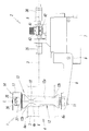
図1及び図2は本発明に係るはんだ供給装置の一実施形態を示すもので、このはんだ供給装置は、例えばはんだ付けロボットに組み込まれ、半導体チップ等の電子部品をプリント基板上に自動的にはんだ付けする場合などに、各はんだ付け部位に向けて線状はんだを自動的に供給するために使用される。 1 and 2 show an embodiment of a solder supply apparatus according to the present invention. This solder supply apparatus is incorporated in, for example, a soldering robot, and an electronic component such as a semiconductor chip is automatically placed on a printed circuit board. It is used to automatically supply linear solder toward each soldering site when soldering.
前記はんだ供給装置は、リール装着部1とはんだ送り部2とを有している。このうちリール装着部1は、線状はんだ3が巻かれたはんだリール4を装着するための部分であり、はんだ送り部2は、前記リール装着部1に装着されたはんだリール4から線状はんだ3を必要長さずつ繰り出し、移送路5に沿ってはんだ付け部位に送り出すための部分である。従って、前記線状はんだ3が送り出される方向を前方とすれば、前記はんだ送り部2は、はんだ供給装置の前方側に位置し、前記リール装着部1は、はんだ供給装置の後方側に位置することになる。
The solder supply device has a
前記はんだリール4は、内部を中心孔4aが軸線L方向に貫通している円筒形の巻芯6と、この巻芯6の軸線L方向両端にそれぞれ取り付けられた円環形の端板6aとからなっていて、前記巻芯6の外周に線状はんだ3が螺旋状かつ多重に巻き付けられている。
The
前記リール装着部1は、前記はんだ送り部2のハウジング7からはんだ供給装置の後方に向けて延出するブラケット8を有している。該ブラケット8は、基端部を前記はんだ送り部2のハウジング7にねじ9で固定され、先端部が自由端となっており、該先端部に、前記はんだリール4を装着するシャフト10の基端部がナット11で固定されることにより、該シャフト10が片持梁状に支持されている。
The
前記シャフト10には、前記はんだリール4が、該はんだリール4の軸線L方向両側に位置する第1の回転カラー12及び第2の回転カラー13を介して回転自在に装着され、該シャフト10の先端に着脱自在に取り付けられたロック部材14で該シャフト10からの脱落が防止されている。
The
図3からも分かるように、前記第1の回転カラー12は、前記はんだリール4の中心孔4a内に嵌合する円柱部12aと、該円柱部12aの一端に形成された円錐部12bとを有する中空状の部材で、該円錐部12bは前記円柱部12aより大径をなし、該第1の回転カラー12が前記シャフト10に回転自在に嵌着され、前記円錐部12bが、小径の先端の一部を前記はんだリール4の中心孔4a内に嵌合させた状態で該はんだリール4の一端にブラケット8側から当接している。
As can be seen from FIG. 3, the first rotating
また、前記第2の回転カラー13は、短円柱部13aと円錐部13bとを有する中空状の部材で、前記シャフト10に回転自在に嵌着され、前記円錐部13bが、小径の先端の一部を前記はんだリール4の中心孔4a内に嵌合させた状態で前記はんだリール4の他端に前記シャフト10の先端側から当接している。
前記第1の回転カラー12及び第2の回転カラー13は、はんだリール4の中心孔4aの内径とシャフト10の外径との径差を補い、該はんだリール4をシャフト10に対して同心状に取り付けるものである。
なお、前記第2の回転カラー13は前記ロック部材14に連結されているが、その連結に関する構成については後述する。
The second rotating
The first rotating
The second
前記ロック部材14は、図4−図6に示すように、前記シャフト10が挿入される挿入孔18を中心に備えた円柱状のボディ17を有している。該ボディ17の内部には、クランプ部材19を収容するための収容室20が形成され、該収容室20の内部に、前記シャフト10が挿通する係止孔19aを中心に備えたリング状の前記クランプ部材19が、該シャフト10に対して傾動自在に収容されている。そして、該クランプ部材19を図4に実線で示すように傾斜させると、前記係止孔19aの内周縁が前記シャフト10の外周に係止してロック部材14が該シャフト10に固定され、前記クランプ部材19を図4に鎖線で示すように非傾斜状態に起立させると、該クランプ部材19の前記シャフト10に対する係止が解除されて前記ロック部材14を該シャフト10から取り外すことができるようになる。
As shown in FIGS. 4 to 6, the
前記クランプ部材19を傾斜させるため、前記ボディ17に形成されたボルト取付孔22には、前記収容室20内に突出するストッパボルト23が進退調節自在なるように取り付けられ、該ストッパボルト23の先端が、前記クランプ部材19の外周端寄りの位置で該クランプ部材19の前面19bに当接し、該クランプ部材19の背面19c側には、前記シャフト10を挟んで対称をなす位置に、一対のばね手段24が該クランプ部材19の背面19cと前記ボディ17の端壁17aとの間に介設され、該ばね手段24でクランプ部材19を該クランプ部材19の前面19b側に向けて押すことにより、該クランプ部材19が、前記ストッパボルト23を支点として図4に実線で示すように傾斜し、前記係止孔19aの内周縁が前記シャフト10の外周に係止するようになっている。
前記ばね手段24はコイルばねからなっていて、該コイルばねが、前記クランプ部材19と前記端壁17aとの間に圧縮状態に配設されている。
In order to incline the
The
また、前記クランプ部材19を非傾斜状態に起立させるため、該クランプ部材19の前記ばね手段24が当接している位置より外周端寄りの位置には、左右一対の操作部25が該クランプ部材19と一体に形成され、該操作部25が、ボディ17の左右両側面に形成された開口26を通じて該ボディ17の外部に露出している。前記開口26は、ボディ17の側面の一部を凹状に窪ませた部分27に形成されている。そして、前記操作部25を指でばね手段24の付勢力に抗する方向に押圧操作することにより、前記クランプ部材19を図4に鎖線で示すように起立させることができるようになっている。
Further, in order to raise the
前記ロック部材14と前記第2の回転カラー13とを連結するため、前記ロック部材14のボディ17には円柱状の連結部29が形成され、該連結部29が前記第2の回転カラー13に形成された連結孔30内に嵌合している。前記連結部29の外周には該連結部29を取り巻くように係止溝31が形成され、前記第2の回転カラー13の短円柱部13aの前記係止溝31を挟んで相対する位置には、互いに平行する一対のピン取付孔32が前記係止溝31に接するように形成され、該ピン取付孔32内に係止ピン33を前記係止溝31に係止した状態に挿入することにより、前記第2の回転カラー13が、前記ロック部材14に、前記シャフト10の軸線L方向には相互に固定的であるが該軸線Lの回りには相対的に回転自在であるように連結されている。
In order to connect the locking
前記係止ピン33は、金属薄板を円筒状に巻いて形成した中空のスプリングピンであって、側面に波形の開口を有し、外径を前記ピン取付孔32の孔径よりより僅かに大きく形成されており、該係止ピン33が前記ピン取付孔32内に弾力的に圧入されている。しかし、この係止ピン33は、中実ピンであっても良い。
The locking
前記リール装着部1はこのような構成を有するもので、前記シャフト10にはんだリール4を装着するときは、先ず、該シャフト10に前記第1の回転カラー12を挿着し、次に、該第1の回転カラー12の円柱部12aの上から前記はんだリール4を挿着し、最後に、前記ロック部材14を、操作部25を指で操作してクランプ部材19をばね手段24の付勢力に抗して非傾斜状態に起立させた状態にしたまま、第2の回転カラー13と共に前記シャフト10の先端に挿着し、該第2の回転カラー13の円錐部13bをはんだリール4に当接させた状態にして前記操作部25から指を離すことにより、前記クランプ部材19がばね手段24により傾斜させられて係止孔19aの内周縁がシャフト10の外周に係止するため、前記ロック部材14が前記シャフト10に固定され、前記はんだリール4の装着が完了する。
The
また、前記はんだリール4を交換するときは、前記操作部25を指で操作して前記クランプ部材19をばね手段24に抗して図4に鎖線で示すように起立させることにより、該クランプ部材19のシャフト10に対する係止を解除し、その状態で前記ロック部材14をシャフト10に沿って移動させることにより、該ロック部材14を前記第2の回転カラー13と共に該シャフト10からから取り外す。そして、前記はんだリール4を新しいものと交換したあと、前記ロック部材14を、第2の回転カラー13と共に、前記取り外す場合と逆の操作でシャフト10に取り付ければ良い。
When the
このように、上記構成を有するリール装着部1は、はんだリール4用の固定手段としてナットやダブルナットを用いた従来のはんだ供給装置に比べ、リールの交換作業を非常に簡単な操作で迅速に行うことができる。
As described above, the
なお、図示した実施形態においては、前記第2の回転カラー13が前記ロック部材14に連結されているが、該第2の回転カラー13は必ずしも前記ロック部材14に連結されていなくても良い。
また、前記はんだリール4の中心孔4aの内径と前記シャフト10の外径との径差が小さく、該はんだリール4をシャフト10に同心状に取り付けることができる場合には、前記第1の回転カラー12及び第2の回転カラー13は省略することもできる。
In the illustrated embodiment, the
Further, when the diameter difference between the inner diameter of the
一方、前記はんだ送り部2は、前記ハウジング7の上面に、前記移送路5の入口側と出口側とに位置するようにはんだ導入部材35とはんだ導出部材36とが設けられる共に、前記はんだ導入部材35の中心孔に通じる中心孔を内部に備えた先細り状の入口ノズル37と、前記はんだ導出部材36の中心孔に通じる中心孔を内部に備えた先細り状の出口ノズル38とが、先細り状をした端部同士を互いに向かい合わせにした状態で前記移送路5に沿って配設されている。そして、前記はんだリール4から繰り出された線状はんだ3が前記はんだ導入部材35から前記入口ノズル37に導入され、前記出口ノズル38からはんだ導出部材36を経てはんだ付け部位に向けて送り出される。
On the other hand, the
前記入口ノズル37と出口ノズル38との間のスペースには、前記移送路5を挟んで相対する位置に、溝切りローラ40とガイドローラ41とが、前記移送路5と直交しかつ互いに平行する軸線を中心に回転自在に配設されている。
前記溝切りローラ40は、中心部にフラックスが充填されている前記線状はんだ3の側面に溝を切る機能と、該線状はんだ3をはんだ付けのタイミングに合わせてはんだ鏝の鏝先に対して必要量ずつ前進させたり後退させたりする機能とを有するもので、前記ボディ17の内部の電動モータ(不図示)に連結されて正逆方向に駆動回転される。前記電動モータはステッピングモータである。
In a space between the
The grooving
このため、前記溝切りローラ40には、外側に向けて鋭く尖った刃先を全周に連続して有するリング状の溝切刃42と、歯車の歯のように間欠的に形成された多数の爪を外周に有するリング状の送り刃43とが、該溝切りローラ40の軸線方向に重ねて配設され、前記送り刃43が、線状はんだ3の側面に食い込んで該線状はんだ3を必要量だけ前進させたり後退させたりし、前記溝切刃42が、線状はんだ3の前進時に該線状はんだ3の側面にフラックス充填領域まで達する溝を連続して切り込むようになっている。
このようにして線状はんだ3に溝を切ると、はんだ付け時にフラックスがはんだ鏝に加熱されて急激に気化しても、該フラックスは前記溝から蒸散するため、爆発現象を生じることがない。
Therefore, the grooving
When a groove is cut in the
一方、前記ガイドローラ41は、外周に線状はんだ3が嵌合するV字状のガイド溝41aを有し、前記溝切りローラ40による線状はんだ3の前進及び後退時に、該線状はんだ3に追随して正逆方向に従動回転するようになっている。
しかし、前記はんだ送り部2の構成はこのようなものに限定されず、線状はんだ3の側面に溝を切り込むように構成されていなくても構わない。
On the other hand, the
However, the configuration of the
1 リール装着部
2 はんだ送り部
3 線状はんだ
4 はんだリール
4a 中心孔
10 シャフト
12 第1の回転カラー
13 第2の回転カラー
14 ロック部材
17 ボディ
18 挿入孔
19 クランプ部材
24 ばね手段
25 操作部
29 連結部
30 連結孔
31 係止溝
32 ピン取付孔
33 係止ピン
L 軸線
DESCRIPTION OF
Claims (3)
前記リール装着部は、基端を該リール装着部に片持梁状に支持されて前記はんだリールの中心孔内に挿入された前記シャフトと、該シャフトの先端に着脱自在に装着されて前記はんだリールが該シャフトから脱落するのを防止するロック部材とを有し、
前記ロック部材は、ボディの内部に傾動自在に収容されたクランプ部材と、該クランプ部材を傾斜方向に付勢するばね手段と、前記クランプ部材を該ばね手段に抗して非傾斜状態にするための操作部とを有し、前記クランプ部材が傾斜状態にあるとき該クランプ部材が前記シャフトに係止して前記ロック部材が前記シャフトに固定され、前記クランプ部材を非傾斜状態にしたとき該クランプ部材の前記シャフトへの係止が解除されて前記ロック部材がシャフトから取り外し可能になるように構成され、
前記ロック部材には、前記シャフトに回転自在に装着されて前記はんだリールの端部に当接する回転カラーが、前記シャフトの軸線方向には相互に固定的であるが該軸線の回りには相対的に回転自在であるように連結されている、
ことを特徴とする線状はんだ供給装置。 A reel mounting portion that rotatably mounts a solder reel wound with linear solder on a shaft, and a solder feeding portion that feeds linear solder from the solder reel and sends it toward a soldering site,
The reel mounting portion is supported by the reel mounting portion in a cantilever shape and is inserted into the center hole of the solder reel, and the reel mounting portion is detachably mounted on the tip of the shaft. A locking member for preventing the reel from falling off the shaft;
The lock member includes a clamp member housed in a tiltable manner inside the body, a spring means for urging the clamp member in a tilt direction, and a non-inclined state of the clamp member against the spring means. And when the clamp member is in an inclined state, the clamp member is locked to the shaft, the lock member is fixed to the shaft, and the clamp member is in a non-inclined state. The locking of the member to the shaft is released, and the lock member is configured to be removable from the shaft ,
The lock member is rotatably attached to the shaft and abuts against the end of the solder reel. The rotary collar is fixed to each other in the axial direction of the shaft, but is relatively around the axis. Connected to be freely rotatable,
The linear solder supply apparatus characterized by the above-mentioned.
Priority Applications (1)
| Application Number | Priority Date | Filing Date | Title |
|---|---|---|---|
| JP2013039441A JP5956366B2 (en) | 2013-02-28 | 2013-02-28 | Linear solder feeder |
Applications Claiming Priority (1)
| Application Number | Priority Date | Filing Date | Title |
|---|---|---|---|
| JP2013039441A JP5956366B2 (en) | 2013-02-28 | 2013-02-28 | Linear solder feeder |
Publications (2)
| Publication Number | Publication Date |
|---|---|
| JP2014166643A JP2014166643A (en) | 2014-09-11 |
| JP5956366B2 true JP5956366B2 (en) | 2016-07-27 |
Family
ID=51616645
Family Applications (1)
| Application Number | Title | Priority Date | Filing Date |
|---|---|---|---|
| JP2013039441A Active JP5956366B2 (en) | 2013-02-28 | 2013-02-28 | Linear solder feeder |
Country Status (1)
| Country | Link |
|---|---|
| JP (1) | JP5956366B2 (en) |
Families Citing this family (1)
| Publication number | Priority date | Publication date | Assignee | Title |
|---|---|---|---|---|
| JP7445301B2 (en) | 2020-06-24 | 2024-03-07 | 株式会社ジャパンユニックス | Linear solder supply device |
Family Cites Families (6)
| Publication number | Priority date | Publication date | Assignee | Title |
|---|---|---|---|---|
| JPS4922349Y1 (en) * | 1970-10-19 | 1974-06-15 | ||
| JPS5237624Y2 (en) * | 1972-09-30 | 1977-08-26 | ||
| JPS51107679U (en) * | 1975-02-26 | 1976-08-27 | ||
| JPS56124646U (en) * | 1980-02-22 | 1981-09-22 | ||
| JPH0544375U (en) * | 1991-11-14 | 1993-06-15 | 三菱電機株式会社 | Wire feeding device |
| JP4847809B2 (en) * | 2006-07-03 | 2011-12-28 | 株式会社ジャパンユニックス | Solder supply apparatus and solder supply method |
-
2013
- 2013-02-28 JP JP2013039441A patent/JP5956366B2/en active Active
Also Published As
| Publication number | Publication date |
|---|---|
| JP2014166643A (en) | 2014-09-11 |
Similar Documents
| Publication | Publication Date | Title |
|---|---|---|
| JP5603252B2 (en) | Gas nozzle mounting device | |
| US9102000B2 (en) | Pushbutton wire guide holder for a welding wire feeder | |
| US7500412B1 (en) | Speed nut and drive gear assembly | |
| US10632559B2 (en) | Indexing drive roll carrier system and method | |
| CA2822047C (en) | Welding wire feeder with pushbutton wire guide holder and alignment tongue; method using a welding wire feeder having such alignment tongue | |
| AU2013305683C1 (en) | Drive roll carrier for welding wire feeder with gear, hub and retainer for the drive roll | |
| JP2017514085A (en) | Stabilized panel fastener | |
| US9931706B2 (en) | Adjustable drive shaft assembly | |
| JP5956366B2 (en) | Linear solder feeder | |
| JP2010125477A (en) | Apparatus for supplying grooves of thread solder containing flux | |
| JP6306912B2 (en) | Welding equipment | |
| JP3959395B2 (en) | Insert insertion device | |
| JP7445301B2 (en) | Linear solder supply device | |
| JP4659911B1 (en) | Grooving feeder for linear solder with flux | |
| JP5612451B2 (en) | Linear solder feeder | |
| JP6278557B2 (en) | Soldering device | |
| CN110919283A (en) | Free direction welding jig | |
| US3946191A (en) | Welding apparatus | |
| JP7368208B2 (en) | Tangless insert insertion tool and method for manufacturing the tangless insert insertion tool | |
| JP2015062945A (en) | Laser welder | |
| JP2017188263A (en) | Soldering jig | |
| JP2007098519A (en) | Loading tool of minute parts |
Legal Events
| Date | Code | Title | Description |
|---|---|---|---|
| A621 | Written request for application examination |
Free format text: JAPANESE INTERMEDIATE CODE: A621 Effective date: 20150109 |
|
| A977 | Report on retrieval |
Free format text: JAPANESE INTERMEDIATE CODE: A971007 Effective date: 20160121 |
|
| A131 | Notification of reasons for refusal |
Free format text: JAPANESE INTERMEDIATE CODE: A131 Effective date: 20160216 |
|
| A521 | Request for written amendment filed |
Free format text: JAPANESE INTERMEDIATE CODE: A523 Effective date: 20160412 |
|
| TRDD | Decision of grant or rejection written | ||
| A01 | Written decision to grant a patent or to grant a registration (utility model) |
Free format text: JAPANESE INTERMEDIATE CODE: A01 Effective date: 20160607 |
|
| A61 | First payment of annual fees (during grant procedure) |
Free format text: JAPANESE INTERMEDIATE CODE: A61 Effective date: 20160616 |
|
| R150 | Certificate of patent or registration of utility model |
Ref document number: 5956366 Country of ref document: JP Free format text: JAPANESE INTERMEDIATE CODE: R150 |
|
| R250 | Receipt of annual fees |
Free format text: JAPANESE INTERMEDIATE CODE: R250 |
|
| R250 | Receipt of annual fees |
Free format text: JAPANESE INTERMEDIATE CODE: R250 |
|
| R250 | Receipt of annual fees |
Free format text: JAPANESE INTERMEDIATE CODE: R250 |
|
| R250 | Receipt of annual fees |
Free format text: JAPANESE INTERMEDIATE CODE: R250 |
|
| R250 | Receipt of annual fees |
Free format text: JAPANESE INTERMEDIATE CODE: R250 |
|
| R250 | Receipt of annual fees |
Free format text: JAPANESE INTERMEDIATE CODE: R250 |