JP5955893B2 - Cable entry protective cover - Google Patents
Cable entry protective cover Download PDFInfo
- Publication number
- JP5955893B2 JP5955893B2 JP2014124273A JP2014124273A JP5955893B2 JP 5955893 B2 JP5955893 B2 JP 5955893B2 JP 2014124273 A JP2014124273 A JP 2014124273A JP 2014124273 A JP2014124273 A JP 2014124273A JP 5955893 B2 JP5955893 B2 JP 5955893B2
- Authority
- JP
- Japan
- Prior art keywords
- insertion port
- cable
- cable insertion
- opening
- utility pole
- Prior art date
- Legal status (The legal status is an assumption and is not a legal conclusion. Google has not performed a legal analysis and makes no representation as to the accuracy of the status listed.)
- Expired - Fee Related
Links
- 230000001681 protective effect Effects 0.000 title claims description 60
- 238000003780 insertion Methods 0.000 claims description 99
- 230000037431 insertion Effects 0.000 claims description 99
- 230000002093 peripheral effect Effects 0.000 claims description 12
- 238000005259 measurement Methods 0.000 description 9
- 238000010586 diagram Methods 0.000 description 6
- 239000000428 dust Substances 0.000 description 4
- XLYOFNOQVPJJNP-UHFFFAOYSA-N water Substances O XLYOFNOQVPJJNP-UHFFFAOYSA-N 0.000 description 4
- 230000006866 deterioration Effects 0.000 description 2
- 238000012986 modification Methods 0.000 description 2
- 230000004048 modification Effects 0.000 description 2
- 239000011150 reinforced concrete Substances 0.000 description 2
- 229920003002 synthetic resin Polymers 0.000 description 2
- 239000000057 synthetic resin Substances 0.000 description 2
- 230000032683 aging Effects 0.000 description 1
- 239000011248 coating agent Substances 0.000 description 1
- 238000000576 coating method Methods 0.000 description 1
- 239000002131 composite material Substances 0.000 description 1
- 230000000694 effects Effects 0.000 description 1
- 238000000605 extraction Methods 0.000 description 1
- 230000035515 penetration Effects 0.000 description 1
- 238000009751 slip forming Methods 0.000 description 1
Images


Landscapes
- Suspension Of Electric Lines Or Cables (AREA)
Description
本発明は、例えば、電柱の途中位置にある開口(以下、ケーブル挿通口という)に挿通された接地線などのケーブルが外部に露出するのを防止できるようにしたケーブル挿通口保護カバーに関する。 The present invention relates to a cable insertion port protective cover that can prevent, for example, a cable such as a ground wire inserted through an opening (hereinafter referred to as a cable insertion port) in the middle of a utility pole from being exposed to the outside.
一般的に、電柱には、変圧器などの電気機器が取り付けられる。該電気機器は、落雷などから保護するために、ケーブル(接地線)と電気的に接続して接地する必要がある。 Generally, electrical equipment such as a transformer is attached to the utility pole. In order to protect the electrical equipment from lightning strikes, it is necessary to electrically connect it to a cable (ground line) and ground it.
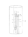
ところで、鉄筋コンクリート製又は複合鉄筋コンクリート製の電柱(柱状体)は、内部が空洞になっており、接地線等のケーブルが内部に挿通される。このため、電柱には、図10〜図13に示す如く、途中位置(例えば、地表から1.8mの位置)に、ケーブルを挿通するためのケーブル挿通口101が形成されるとともに、電柱100の上部(例えば、地表から8mの位置)に、ケーブルを引き出すための引出口102が形成される。さらに、ケーブル挿通口101よりも上方(地表から2mの位置)に、ケーブルを介して電気機器を接地するための接地測定端子Tが設けられる。
By the way, the inside of the electric pole (columnar body) made of reinforced concrete or composite reinforced concrete is hollow, and a cable such as a ground wire is inserted through the inside. For this reason, as shown in FIGS. 10 to 13, the utility pole is provided with a
電柱100内に挿通されるケーブルには、一般的に、電柱100の内部から引出口102を通って電気機器(図示せず)に接続されたケーブルE1と、地中に埋設された接地極(図示せず)に接続されたケーブルE2とがある。各ケーブルE1,E2は、電柱100に内挿されて、ケーブル挿通口101から外部に引き出されて、電柱100の外面に沿って配置されて、接地測定端子Tに接続される。
Generally, a cable inserted into the
そして、接地測定端子Tにおいて、電気機器に接続されたケーブルE1と、接地極に接続されたケーブルE2とが電気的に接続される。これにより電気機器が接地されることになる。 At the ground measurement terminal T, the cable E1 connected to the electric device and the cable E2 connected to the ground electrode are electrically connected. As a result, the electric device is grounded.
ところで、接地測定端子Tに接続されるケーブルE1,E2は、電柱100の外面に沿って配置されるため、ケーブル挿通口101から露出する。この露出部位は、合成樹脂製の保護管Pによって覆われ、露出するケーブルE1,E2に対する安全確保が図られている。
By the way, since the cables E1 and E2 connected to the ground measurement terminal T are arranged along the outer surface of the
通常の場合、図10に示す如く、接地測定端子Tにおいて、接地抵抗が測定されるが、経時変化による劣化によって接地抵抗が基準値から外れた場合は、図11に示す如く、電柱100のケーブル挿通口から露出したケーブルE2に、新たなケーブルE20,E21が分岐接続されて、ケーブル挿通口101に挿通されて電柱100の外面に配置されて接地される。そして、測定した接地抵抗値が基準値の範囲内に収まるようにする。
In the normal case, the ground resistance is measured at the ground measurement terminal T as shown in FIG. 10, but when the ground resistance deviates from the reference value due to deterioration due to aging, the cable of the
また、図12に示す如く、接地測定端子Tに接続されたケーブルE2に、分岐接続されたケーブルE20が接地される場合もある。 In addition, as shown in FIG. 12, the cable E20 that is branched and connected to the cable E2 that is connected to the ground measurement terminal T may be grounded.
また、図13に示す如く、接地測定端子Tに接続されたケーブルE2に、分岐接続された複数のケーブルE20,E21が接地される場合もある。 Further, as shown in FIG. 13, a plurality of cables E20 and E21 that are branched and connected may be grounded to the cable E2 that is connected to the ground measurement terminal T.
ところで、電柱のケーブル挿通口を覆うとともに、ケーブルを電柱の内部に予め配置しておくためのケーブル挿通口保護カバーが提供されている(特許文献1参照)。この保護カバーは、ケーブル挿通口に装着される筒状の挿通部材と、該挿通部材の開口を閉塞する蓋部材とを備える。そして、蓋部材の上端部には、ケーブルを電柱のケーブル挿通口に挿通するための開口が形成されている。 By the way, while covering the cable insertion port of an electric pole, the cable insertion port protective cover for previously arrange | positioning a cable inside an electric pole is provided (refer patent document 1). The protective cover includes a cylindrical insertion member attached to the cable insertion port, and a lid member that closes the opening of the insertion member. And the opening for inserting a cable in the cable insertion port of a utility pole is formed in the upper end part of a cover member.
上記構成のケーブル挿通口保護カバーは、ケーブルを、蓋部材の開口を通してケーブル挿通口に挿通できても、電柱の外面に沿って配置されたケーブルを覆う保護管を接続できる構成にはなっていない。このため、保護カバーと保護管との間でケーブルが露出することになり、ケーブルを保護できなくなる。その結果、露出したケーブルの部位に人が接触する可能性があり、人の手の届く範囲での安全性を確保できないという問題がある。 The cable insertion port protective cover having the above-described configuration is not configured to connect a protective tube that covers the cable disposed along the outer surface of the utility pole even though the cable can be inserted into the cable insertion port through the opening of the lid member. . For this reason, the cable is exposed between the protective cover and the protective tube, and the cable cannot be protected. As a result, there is a possibility that a person may come into contact with the exposed cable portion, and there is a problem that safety within the reach of the person cannot be secured.
そこで、本発明は、上記課題に鑑み、電柱の途中位置にある開口(ケーブル挿通口)に挿通された接地線などのケーブルが外部に露出するのを防止できるケーブル挿通口保護カバーを提供することを目的とする。 Then, this invention provides the cable insertion port protective cover which can prevent that cables, such as a ground wire inserted in the opening (cable insertion port) in the middle position of a utility pole, are exposed outside in view of the said subject. With the goal.
本発明に係るケーブル挿通口保護カバーは、柱状体の周壁に形成された開口であって、ケーブルの挿通された開口を覆う本体部と、該開口に挿通されて周壁の外周に沿って配置されているケーブルを覆う保護管の端部を被覆する被覆部であって、本体部に連続して複数形成された被覆部と、本体部の内面から突出し、柱状体の開口の周縁部に対して係止可能な係止体とを備え、それぞれの被覆部は、保護管の端部が挿入される挿入口であって、切除可能な蓋により塞がれる挿入口を有することを特徴とする。
The cable insertion port protective cover according to the present invention is an opening formed in the peripheral wall of the columnar body, and is disposed along the outer periphery of the main body part covering the opening through which the cable is inserted and the opening. A covering portion that covers the end of the protective tube that covers the cable, and a plurality of covering portions that are continuously formed on the main body portion, and protrudes from the inner surface of the main body portion, with respect to the peripheral edge portion of the opening of the columnar body Each covering portion is an insertion port into which an end of the protective tube is inserted, and has an insertion port that is closed by a resectable lid .
かかる構成によれば、柱状体の周壁に形成された開口(軸線に対して直交する位置に形成された開口)が本体部によって覆われるため、開口に挿通されているケーブルの露出部位を本体部で保護できる。また、柱状体の開口の周縁部に沿って配置される保護管の端部(柱状体の外面に配置される保護管の端部)が、本体部に連続して形成された被覆部によって被覆されるため、柱状体の開口から保護管の端部に挿通されたケーブル(柱状体の開口と保護管の端部との間で露出したケーブル)を保護できる。したがって、柱状体の開口から保護管の端部に挿通されたケーブルにおいて、外部に露出する部分がなくなるので、人の手の届く範囲での安全性を確保することができる。 According to such a configuration, since the opening formed in the peripheral wall of the columnar body (the opening formed at a position orthogonal to the axis) is covered by the main body, the exposed portion of the cable inserted through the opening is the main body. Can be protected. Further, the end portion of the protective tube arranged along the peripheral edge of the opening of the columnar body (the end portion of the protective tube arranged on the outer surface of the columnar body) is covered with a covering portion formed continuously with the main body portion. Therefore, the cable (the cable exposed between the opening of the columnar body and the end of the protective tube) inserted from the opening of the columnar body into the end of the protective tube can be protected. Therefore, in the cable inserted from the opening of the columnar body to the end of the protective tube, there is no portion exposed to the outside, and thus safety within the reach of human hands can be ensured.
また、柱状体の開口に、本体部の内面から突出した係止体が挿入され、柱状体の開口の内壁に係止体が係止し、柱状体に本体部が固定されて、柱状体の開口が本体部によって覆われる。
また、本体部の両側に被覆部を形成したため、保護管が配置されていない側の挿入口は蓋により塞がれた状態にしておくことで、本体部の内部に水や塵埃が入り込むことを防止できる。一方、保護管が配置されている側の挿入口は、蓋を切除して挿入口を開放し、開放された挿入口に、保護管の端部を挿入して、保護管の端部を被覆部で覆う。
In addition, a locking body protruding from the inner surface of the main body is inserted into the opening of the columnar body, the locking body is locked to the inner wall of the opening of the columnar body, and the main body is fixed to the columnar body. The opening is covered by the main body.
In addition, because the cover is formed on both sides of the main body, water and dust can get inside the main body by keeping the insertion port on the side where the protective tube is not placed closed by the lid. Can be prevented. On the other hand, for the insertion port on the side where the protective tube is arranged, the lid is cut off to open the insertion port, and the end of the protective tube is inserted into the opened insertion port to cover the end of the protective tube Cover with part.
また、本発明に係るケーブル挿通口保護カバーの一態様によれば、本体部は、柱状体に対向し、柱状体の外面に沿って当接可能な当接面を有することが好ましい。 Moreover, according to the one aspect | mode of the cable insertion opening protective cover which concerns on this invention, it is preferable that a main-body part has a contact surface which opposes a columnar body and can contact | abut along the outer surface of a columnar body.
かかる構成によれば、本体部が開口を覆った状態で、柱状体に対向する当接面が柱状体の外面に沿って当接するので、柱状体の外面と本体部の開口端面との間に隙間ができず、柱状体の開口から雨水などの水や塵埃が入ることがなく、ケーブルを保護できる。 According to such a configuration, the contact surface facing the columnar body abuts along the outer surface of the columnar body in a state where the main body portion covers the opening, and therefore, between the outer surface of the columnar body and the opening end surface of the main body unit. There is no gap, and water such as rainwater and dust do not enter from the opening of the columnar body, and the cable can be protected.
以上のように、本発明によれば、電柱の途中位置にある開口(ケーブル挿通口)に挿通された接地線などのケーブルが外部に露出するのを防止できる、といった優れた効果を奏し得る。 As described above, according to the present invention, it is possible to achieve an excellent effect that it is possible to prevent a cable such as a ground wire inserted through an opening (cable insertion port) at an intermediate position of a utility pole from being exposed to the outside.
本発明の一実施形態に係るケーブル挿通口保護カバー(以下、単に保護カバーという場合もある。)について図1〜図9(a),(b)を参照しながら説明する。 A cable insertion port protective cover (hereinafter sometimes simply referred to as a protective cover) according to an embodiment of the present invention will be described with reference to FIGS. 1 to 9A and 9B.
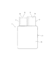
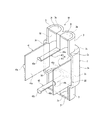
本実施形態に係るケーブル挿通口保護カバーは、図1〜図3に示す如く、電柱100の周壁に形成されたケーブル挿通口101を覆う保護カバー1の本体部2と、該ケーブル挿通口101に挿通されて周壁の外周に沿って配置されているケーブル(接地線)E1,E2を覆う保護管Pの端部を被覆する被覆部3,3と、本体部2の内面から突出し、ケーブル挿通口101の周縁部に係止可能な係止体4とを備える。
As shown in FIGS. 1 to 3, the cable insertion port protective cover according to the present embodiment includes a
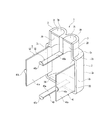
本体部2は、上壁2bと、左右の側壁2c、2cと、底壁2dと、電柱100のケーブル挿通口101(電柱100の軸線に対して直交する位置に形成された開口)に対向する覆壁2eとを備える。
The
そして、上壁2bと、左右の側壁2c、2cと、底壁2dと、覆壁2eとによって、電柱100のケーブル挿通口101の周縁部が囲まれる。
And the peripheral part of the
また、上壁2bと、左右の側壁2c、2cと、底壁2dと、覆壁2eと、後述する被覆部3,3の内壁30,30とによって開口2aが画定される。この開口2aは、電柱100のケーブル挿通口101の開口面積よりも大きい開口面積を有し、ケーブル挿通口101を覆うことができる。
Moreover, the opening 2a is demarcated by the
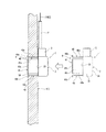
本体部2の開口2aの開口端面は、電柱100に対向し、該開口端面に、電柱100の外面に沿って当接する断面が円弧状の当接面20が形成されている(図3参照)。
The opening end surface of the
そして、本体部2が電柱100のケーブル挿通口101を覆った状態で、当接面20が電柱100の外面に沿って当接するので、電柱100の外面と本体部2の当接面20との間に隙間ができず、電柱100のケーブル挿通口101から雨水などの水や塵埃が入ることがなく、ケーブル(接地線)E1,E2を保護できる。
Since the
被覆部3,3は、本体部2の上壁2bから電柱100の軸線に沿って延びる方向(上方向)に連続して並んで延出される。そして、それぞれの被覆部3,3は、電柱100の外面に配置される合成樹脂製の保護管Pの端部が挿入される円弧状の内壁30,30を有する。また、それぞれの被覆部3,3には、保護管Pの端部が挿入される挿入口3a,3aが形成され、該挿入口3a,3aは、切除可能な蓋31,31により塞がれている。
The covering
そして、保護管Pが配置されていない側の挿入口3aは蓋31により塞がれた状態にしておくことで、本体部2の内部に水や塵埃が入り込むことを防止できる。一方、保護管Pが配置されている側の挿入口3aは、蓋31を切除して挿入口3aを開放し、開放された挿入口3aに、保護管Pの端部を挿入して、保護管Pの端部を被覆部3で覆う。
The
これによって、電柱100のケーブル挿通口101と保護管Pとの間のケーブルE1,E2の露出部位を保護できる。
As a result, the exposed portions of the cables E1, E2 between the
係止体4は、一対の第1係止体40,40と、一対の第2係止体41,41とを備える。一対の第1係止体40,40は、本体部2の上壁2b(被覆部3,3の間)と、底壁2dの幅方向中央部とからケーブル挿通口101に向かって突出し、ケーブル挿通口101に対して上下に並列して配置されている。
The locking body 4 includes a pair of
第1係止体40は、ケーブル挿通口101に向かって延出される延出部40aであって、ケーブル挿通口101に挿通される延出部40aと、延出部40aの端部から外方向に突出して形成される係止部40bであって、ケーブル挿通口101の内壁に係止する係止部40bとを備える。
The
延出部40aは、第2係止体41よりも幅寸法が小さく、ケーブル挿通口101の内壁の厚さと同一長さを有している。
The extending
一対の第2係止体41,41は、側壁2c,2cの内面からケーブル挿通口101に向かって突出し、ケーブル挿通口101に対して左右に並列して配置されている。
The pair of
第2係止体41は、ケーブル挿通口101に挿通される延出部41aと、延出部41aの端部から外方向に突出して形成された係止部41bであって、ケーブル挿通口101の内壁に係止する係止部41bとを備える。
The
延出部41aは、第1係止体40の延出部40aよりも幅寸法が大きく、ケーブル挿通口101の内壁の厚さと同一長さを有している。
The extending
そして、第1係止体40,40及び第2係止体41,41は、ケーブル挿通口101の内壁に対して自己の弾性力により係止できるように、図3に示す如く、第1係止体40,40の間隔及び第2係止体41,41の間隔が、ケーブル挿通口101の内壁に摺接しつつ、内壁の角部に係止する間隔に設定されている。
As shown in FIG. 3, the
これにより、第1係止体40,40及び第2係止体41,41は、ケーブル挿通口101に対して直交方向に挿通されて、第1係止体40,40及び第2係止体41,41がケーブル挿通口101の内壁にそれぞれ係止して、ケーブル挿通口101に対してケーブル挿通口保護カバー1が取り付けられる。
As a result, the
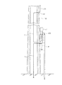
つぎにケーブル挿通口保護カバー1の使用態様について説明する。まず、両被覆部3,3の挿入口3a,3aの蓋31,31を切除して、挿入口3a,3aを予め開放しておく。
Next, how the cable insertion port
つぎに、図3に示す如く、保護管Pが配置された状態の電柱100のケーブル挿通口101に、保護カバー1の本体部2の第1係止体40,40及び第2係止体41,41を矢印の方向に挿入し、第1係止体40,40の係止部40b,40b及び第2係止体41,41の係止部41b,41bを、ケーブル挿通口101の内壁に係止させる。
Next, as shown in FIG. 3, the
これにより、保護カバー1が位置ずれすることなく固定され、ケーブル挿通口101が保護カバー1によって覆われる。ケーブル挿通口101が覆われると、保護カバー1の本体部2の当接面20が、電柱100のケーブル挿通口101の近傍の外面に当接し、被覆部3に保護管Pの端部が被覆される。
As a result, the
その結果、電柱100のケーブル挿通口101が保護カバー1の本体部2によって覆われて、ケーブル挿通口101に挿通されているケーブルE1,E2の露出部位が保護カバー1の本体部2で保護できる。
As a result, the
このように、保護管Pの端部を被覆部3で被覆することで、ケーブル挿通口101と保護管Pとの間のケーブルE1,E2の露出部位を保護できる。したがって、ケーブル挿通口101に挿通されたケーブルE1,E2において、外部に露出する部分がなくなるので、人の手の届く範囲での安全性を確保することができる。
Thus, by covering the end portion of the protective tube P with the covering
なお、本発明に係るケーブル挿通口保護カバーは、前記実施形態に限定することなく種々変更することができる。 In addition, the cable insertion port protective cover which concerns on this invention can be variously changed without limiting to the said embodiment.
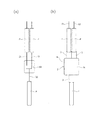
例えば、前記実施形態の場合、本体部2の上側に一対の被覆部3,3を備えるとともに、本体部2の上下に一対の第1係止体40,40を備えるようにしたが、例えば、図4及び図5に示す如く、本体部2の底壁2dの中央から下方に延出される1つの被覆部3を備えるとともに、該被覆部3を挟んだ両側に、ケーブル挿通口101に向かって延出される一対の第1係止体40,40を備えるようにしてもよい。この場合も、前記実施形態と同様に、上側の両被覆部3,3の挿入口3a,3aの蓋31、及び下側の被覆部3の挿入口3aの蓋31をそれぞれ切除して、それぞれの挿入口3aを予め開放する。
For example, in the case of the above-described embodiment, a pair of covering
そして、図6(a)に示す如く、保護管Pが配置された状態の電柱100のケーブル挿通口101に、保護カバー1Aの本体部2の第1係止体40,40、及び第2係止体41,41 を挿入して係止させると、図6(b)に示す如く、ケーブル挿通口101が保護カバー1Aによって覆われる。
Then, as shown in FIG. 6A, the first engaging
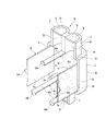
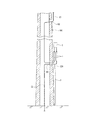
また、図7及び図8に示す如く、本体部2の底壁2dの両側に、下方に向かって延出される一対の被覆部3,3を備えるようにしてもよい。この場合も、前記実施形態と同様に、上側の両被覆部3,3の挿入口3a,3a、及び下側の両被覆部3,3の挿入口3a,3aの蓋31を切除して、それぞれの挿入口3aを予め開放する。
Further, as shown in FIGS. 7 and 8, a pair of covering
そして、図9(a)に示す如く、保護管Pが配置された状態の電柱100のケーブル挿通口101に、保護カバー1Bの本体部2の第1係止体40,40及び第2係止体41,41 を挿入して係止させると、図9(b)に示す如く、電柱100のケーブル挿通口101が保護カバー1Bによって覆われる。
And as shown to Fig.9 (a), the
また、前記実施形態の場合、ケーブル挿通口保護カバー1,1A,1Bを、電柱100のケーブル挿通口101に取り付けるようにしたが、引出口102にも取り付けることは可能である。
In the case of the embodiment, the cable insertion port protection covers 1, 1 </ b> A, and 1 </ b> B are attached to the
1,1A,1B…ケーブル挿通口保護カバー、2…本体部、2a…開口、2b…上壁、2c…側壁、2d…底壁、2e…覆壁、3…被覆部、3a…挿入口、20…当接面、30…内壁、31…蓋、4…係止体、40…第1係止体,41…第2係止体、40a,41a…延出部、40b,41b…係止部、100…電柱、101…ケーブル挿通口、102…引出口、E1,E2,E20,E21…ケーブル、P…保護管、T…接地測定端子
DESCRIPTION OF
Claims (2)
該開口に挿通されて周壁の外周に沿って配置されているケーブルを覆う保護管の端部を被覆する被覆部であって、本体部に連続して複数形成された被覆部と、
本体部の内面から突出し、柱状体の開口の周縁部に対して係止可能な係止体とを備え、
それぞれの被覆部は、保護管の端部が挿入される挿入口であって、切除可能な蓋により塞がれる挿入口を有することを特徴とするケーブル挿通口保護カバー。 An opening formed in the peripheral wall of the columnar body, the body portion covering the opening through which the cable is inserted;
A covering portion that covers the end of the protective tube covering the cable is inserted into the opening and are arranged along the outer periphery of the peripheral wall, and a cover portion which is plurally formed continuously to the main body portion,
A locking body that protrudes from the inner surface of the main body and can be locked to the peripheral edge of the opening of the columnar body ;
Each of the covering portions is an insertion port into which an end portion of the protective tube is inserted, and has an insertion port that is closed by a resectable lid .
2. The cable insertion port protective cover according to claim 1, wherein the main body portion has a contact surface facing the columnar body and capable of contacting along the outer surface of the columnar body.
Priority Applications (1)
| Application Number | Priority Date | Filing Date | Title |
|---|---|---|---|
| JP2014124273A JP5955893B2 (en) | 2014-06-17 | 2014-06-17 | Cable entry protective cover |
Applications Claiming Priority (1)
| Application Number | Priority Date | Filing Date | Title |
|---|---|---|---|
| JP2014124273A JP5955893B2 (en) | 2014-06-17 | 2014-06-17 | Cable entry protective cover |
Publications (2)
| Publication Number | Publication Date |
|---|---|
| JP2016005361A JP2016005361A (en) | 2016-01-12 |
| JP5955893B2 true JP5955893B2 (en) | 2016-07-20 |
Family
ID=55224284
Family Applications (1)
| Application Number | Title | Priority Date | Filing Date |
|---|---|---|---|
| JP2014124273A Expired - Fee Related JP5955893B2 (en) | 2014-06-17 | 2014-06-17 | Cable entry protective cover |
Country Status (1)
| Country | Link |
|---|---|
| JP (1) | JP5955893B2 (en) |
Family Cites Families (5)
| Publication number | Priority date | Publication date | Assignee | Title |
|---|---|---|---|---|
| JPH01103174U (en) * | 1987-12-26 | 1989-07-12 | ||
| JPH01123418U (en) * | 1988-02-18 | 1989-08-22 | ||
| JPH0514670Y2 (en) * | 1989-04-17 | 1993-04-19 | ||
| JP3504221B2 (en) * | 2000-08-11 | 2004-03-08 | 未来工業株式会社 | Pipe end protection cover and piping structure of protection tube |
| JP5060362B2 (en) * | 2008-03-28 | 2012-10-31 | 未来工業株式会社 | Wiring / piping material extraction tool |
-
2014
- 2014-06-17 JP JP2014124273A patent/JP5955893B2/en not_active Expired - Fee Related
Also Published As
| Publication number | Publication date |
|---|---|
| JP2016005361A (en) | 2016-01-12 |
Similar Documents
| Publication | Publication Date | Title |
|---|---|---|
| KR101407532B1 (en) | Waterproofing electrical outlet | |
| KR102298899B1 (en) | Electric device | |
| US7556523B2 (en) | Wall outlet | |
| KR200451085Y1 (en) | Protective cover for insulated connector | |
| US9680292B2 (en) | Electrical device protective housing | |
| US20140048307A1 (en) | Cable-termination device | |
| WO2009049187A3 (en) | Waterproof data cable with foam filler and water blocking material | |
| US20100200263A1 (en) | Electrical junction box for tool-less installation of power cables | |
| KR102156593B1 (en) | Protecting Case For Electic Concent | |
| JP5955893B2 (en) | Cable entry protective cover | |
| JP2015133822A (en) | Cable connection structure and cable connection method | |
| KR100766576B1 (en) | Protective cover installation structure of power cable | |
| JP5955892B2 (en) | Cable entry protective cover | |
| CN107408426B (en) | Cable and method for making cable | |
| ES2806809T3 (en) | Set as a junction box replacement and method of installing the junction box | |
| KR101259168B1 (en) | Protecting pipe of electric wires for led | |
| JP3117134U (en) | Extension cord | |
| JP2015011945A (en) | connector | |
| JP5922186B2 (en) | Protective cover | |
| CA2887784A1 (en) | Terminal for detecting an optically invisible network, apparatus including such a detection terminal, and method for detecting an optically invisible network | |
| JP7665681B2 (en) | Concrete pole | |
| KR20190002926U (en) | Holder for electric cable cover | |
| GB2491342A (en) | Waterproof electrical enclosure | |
| KR200416246Y1 (en) | Prefabricated Cable Insulation Cover | |
| CN204405905U (en) | The transparent fixed bin of covered wire cable |
Legal Events
| Date | Code | Title | Description |
|---|---|---|---|
| A977 | Report on retrieval |
Free format text: JAPANESE INTERMEDIATE CODE: A971007 Effective date: 20160408 |
|
| A131 | Notification of reasons for refusal |
Free format text: JAPANESE INTERMEDIATE CODE: A131 Effective date: 20160415 |
|
| A521 | Request for written amendment filed |
Free format text: JAPANESE INTERMEDIATE CODE: A523 Effective date: 20160524 |
|
| TRDD | Decision of grant or rejection written | ||
| A01 | Written decision to grant a patent or to grant a registration (utility model) |
Free format text: JAPANESE INTERMEDIATE CODE: A01 Effective date: 20160610 |
|
| A61 | First payment of annual fees (during grant procedure) |
Free format text: JAPANESE INTERMEDIATE CODE: A61 Effective date: 20160615 |
|
| R150 | Certificate of patent or registration of utility model |
Ref document number: 5955893 Country of ref document: JP Free format text: JAPANESE INTERMEDIATE CODE: R150 |
|
| LAPS | Cancellation because of no payment of annual fees |