JP5955174B2 - Ion generator - Google Patents
Ion generator Download PDFInfo
- Publication number
- JP5955174B2 JP5955174B2 JP2012204739A JP2012204739A JP5955174B2 JP 5955174 B2 JP5955174 B2 JP 5955174B2 JP 2012204739 A JP2012204739 A JP 2012204739A JP 2012204739 A JP2012204739 A JP 2012204739A JP 5955174 B2 JP5955174 B2 JP 5955174B2
- Authority
- JP
- Japan
- Prior art keywords
- mist
- air
- air supply
- ion generator
- housing
- Prior art date
- Legal status (The legal status is an assumption and is not a legal conclusion. Google has not performed a legal analysis and makes no representation as to the accuracy of the status listed.)
- Expired - Fee Related
Links
Images


Description
本発明は、イオンにより肌水分量を向上させるイオン発生装置に関する。 The present invention relates to an ion generator that improves skin moisture content by ions.
イオンによって居住空間内の空気を清浄化する空気清浄機が実用化されている。このような空気清浄機では、送風機が外部から吸い込んだ空気が流れる送風路内にプラスイオン及びマイナスイオンを発生させるイオン発生器が配設され、発生したイオンを吹出口から吹き出される空気と共に外部へ放出させている(例えば、特許文献1を参照)。放出されたイオンは、室内等の居住空間において空気中の浮遊細菌等を不活性化させ、死滅させると共に臭気成分を変性させる。その結果、居住空間内の空気が清浄化される。 Air cleaners that purify the air in living spaces with ions have been put into practical use. In such an air purifier, an ion generator for generating positive ions and negative ions is disposed in a blower passage through which air sucked from the outside of the blower flows, and the generated ions are externally combined with the air blown out from the blowout port. (See, for example, Patent Document 1). The released ions inactivate airborne bacteria in the air in a living space such as a room, kill them and denature odor components. As a result, the air in the living space is cleaned.
また、近年では、イオンによる除菌効果だけでなく、人の肌に照射することにより肌水分量を向上させる保湿効果が注目されつつある。例えば、プラスイオンとして、H+ (H2 O)m (mは0又は任意の自然数)、マイナスイオンとして、O2 -(H2 O)n (nは0又は任意の自然数)を人の肌に照射した場合、肌水分量が増加することが知られている(特許文献2を参照)。H+ イオン及びO2 -イオンを同時的に照射することで肌表面に・OH基が付着し、肌表面が局所的に親水化されて水分子が付着し、肌に浸透しやすくなるという効果が得られる。 In recent years, attention has been focused not only on the sterilization effect by ions, but also on the moisturizing effect of improving the skin moisture content by irradiating human skin. For example, H + (H 2 O) m (m is 0 or any natural number) as positive ions, and O 2 − (H 2 O) n (n is 0 or any natural number) as negative ions. It is known that the amount of moisture in the skin increases when irradiating (see Patent Document 2). By irradiating H + ions and O 2 - ions simultaneously, OH groups are attached to the skin surface, the skin surface is locally hydrophilized and water molecules are attached, making it easier to penetrate the skin. Is obtained.
イオン発生装置において発生させたイオンを人の肌に照射する場合、通常、送風ファンなどを用いて装置内で空気流を発生させるため、イオン発生装置のハウジングには、外気を吸入するための吸気口及びイオンを含んだ空気流を送り出すための送気口が設けられる。 When irradiating human skin with ions generated in an ion generator, an air flow is usually generated in the apparatus using a blower fan or the like. An air supply port is provided for sending out an air flow containing the mouth and ions.
ところで、このようなイオン発生装置を利用者が携帯できるように小型化した場合、利用者がハウジングを把持した際に吸気口を不用意に塞いでしまうことがある。吸気口が塞がれてしまった場合、装置内で十分な空気流を発生させることができず、風量を確保することができないので、照射するイオンの量を規定値以上に保つことができないという問題が発生する。 By the way, when such an ion generator is reduced in size so that the user can carry it, the intake port may be inadvertently blocked when the user grips the housing. If the air intake is blocked, it will not be possible to generate a sufficient air flow in the device, and the air volume cannot be secured, so the amount of ions to be irradiated cannot be kept above the specified value. A problem occurs.
本発明は、斯かる事情に鑑みてなされたものであり、吸気口が利用者の手によって塞がれることを防止して、風量を確保することができるイオン発生装置を提供することを目的とする。 This invention is made in view of such a situation, and it aims at providing the ion generator which can prevent that an inlet port is obstruct | occluded by a user's hand and can ensure an air volume. To do.
本発明に係るイオン発生装置は、吸気口及び送気口を有し、前記吸気口と前記送気口とを連通する通気路の中途に設けられ、前記吸気口から前記送気口への空気流を発生させる送風手段と、プラスイオン及びマイナスイオンを各別に発生させて前記通気路へ放出するイオン発生手段とを収容し、ユーザにより把持される有底筒状の送風ハウジングと、液体を貯留するタンクと、該タンクに貯留された液体を霧状化する霧状化手段と、該霧状化手段により霧状化した液体を外部へ噴射する噴射手段とを収容し、前記送風ハウジングの上側に連接されたタンクハウジングとを備え、前記送風ハウジングの上端部の幅寸法を中央部の幅寸法より小さくして、前記送風ハウジングの上端部における外周面の全周に亘って段差面を形成してあり、前記段差面に前記吸気口を設けてあることを特徴とする。 An ion generator according to the present invention has an intake port and an air supply port, and is provided in the middle of a ventilation path that communicates the intake port and the air supply port, and air from the intake port to the air supply port A blower means for generating a flow, an ion generator means for generating positive ions and negative ions separately and releasing them into the air passage, and a bottomed cylindrical blower housing held by a user, and storing liquid And a spraying means for spraying the liquid atomized by the atomizing means to the outside, and an upper side of the blower housing. and a concatenated tank housing, the width of the upper end portion of the blower housing and smaller than the width of the central portion to form a stepped surface over the entire circumference of the outer peripheral surface of the upper end portion of the blower housing There Te, said stage Characterized in that the surface is provided with the air inlet.
本発明に係るイオン発生装置は、前記段差面に前記送気口を設けてあることを特徴とする。 The ion generator according to the present invention is characterized in that the air supply port is provided in the stepped surface .
本発明に係るイオン発生装置は、前記吸気口を、前記送気口より前記タンクハウジング寄りに設けてあることを特徴とする。 The ion generator according to the present invention is characterized in that the intake port is provided closer to the tank housing than the air supply port.
本発明に係るイオン発生装置は、前記送風ハウジングの軸長方向に垂直な断面が円形又は楕円形をなすことを特徴とする。 The ion generator according to the present invention is characterized in that a cross section perpendicular to the axial length direction of the blower housing is circular or elliptical.
本発明にあっては、送風ハウジング内に設けたイオン発生手段により各別に発生させたプラスイオン及びマイナスイオンを送気口を通じて所定方向へ送り出すと共に、送風ハウジングに連設されるタンクハウジング内で霧状化した液体を、イオンを送り出す方向(前記所定方向)と同方向に噴射する構成としている。 In the present invention, positive ions and negative ions generated individually by the ion generating means provided in the blower housing are sent out in a predetermined direction through the air feed port, and the mist is generated in the tank housing connected to the blower housing. The shaped liquid is ejected in the same direction as the direction in which ions are sent out (the predetermined direction).
送気口より送り出したプラスイオン及びマイナスイオンは、その多くが送気口の付近で結合しないため、照射部位に到達し易くなる。イオン発生手段により発生させるイオンを、例えば、H+ イオン及びO2 -イオンとした場合、照射部位である肌表面に・OH基が付着し、肌表面が局所的に親水化されて水分子が付着しやすい状態となる。本願では、イオンの照射と共に、イオンの照射方向と同方向にミストを噴射することが可能であるため、照射部位である肌表面付近にてイオン及びミストが混在した状態となる。このため、肌表面に付着した・OH基の周囲に十分な水分子が供給され、より効率的にナノサイズの水分子が生成される。 Most of the positive ions and negative ions sent out from the air supply port do not bind in the vicinity of the air supply port, so that they easily reach the irradiation site. If the ions generated by the ion generating means are, for example, H + ions and O 2 - ions, OH groups are attached to the skin surface that is the irradiation site, the skin surface is locally hydrophilized, and water molecules are generated. It becomes easy to adhere. In the present application, since the mist can be ejected in the same direction as the ion irradiation direction together with the ion irradiation, the ions and the mist are mixed in the vicinity of the skin surface that is the irradiation site. Therefore, sufficient water molecules are supplied around the OH group attached to the skin surface, and nano-sized water molecules are generated more efficiently.
また、本発明では、タンクハウジング寄りの部分に形成した送風ハウジングの窪みに吸気口を設けているため、送風ハウジングを利用者の手により把持した際、吸気口と利用者の手との間に一定の空間が確保され、利用者の手によって吸気口が完全に塞がれることが防止される。 Further, in the present invention, since the air inlet is provided in the recess of the blower housing formed in the portion near the tank housing, when the blower housing is gripped by the user's hand, it is between the air intake and the user's hand. A certain space is secured, and the intake port is prevented from being completely blocked by the user's hand.
本発明によれば、イオンの照射方向と同方向にミストを噴射するため、例えば、照射するイオンをH+ イオン及びO2 -イオンとした場合、肌表面に付着した・OH基の周囲に十分な水分子を供給することができ、より効率的にナノサイズの水分子を生成させることができ、この結果、水分子が肌に浸透しやすくなり、肌水分量を増加させることができるという効果を奏する。 According to the present invention, since the mist is ejected in the same direction as the ion irradiation direction, for example, when the ions to be irradiated are H + ions and O 2 − ions, the surface is sufficiently attached around the surface of the OH group. Water molecules can be supplied, and nano-sized water molecules can be generated more efficiently. As a result, water molecules can easily penetrate into the skin and increase the amount of moisture in the skin. Play.
また、本発明では、送風ハウジングに形成した窪みに吸気口を設けているため、送風ハウジングを利用者の手により把持した際、利用者の手によって吸気口が完全に塞がれることが防止されるので、吸気口から送気口に至る通気路における風量を確保することができ、送気口から空気と共に送り出すイオンの量を規定値以上に保つことができる。 Further, in the present invention, since the air inlet is provided in the recess formed in the air blowing housing, the air inlet is prevented from being completely blocked by the user's hand when the air blowing housing is gripped by the user's hand. Therefore, it is possible to secure the air volume in the air passage from the intake port to the air supply port, and it is possible to keep the amount of ions sent out together with the air from the air supply port above a specified value.
本発明をその実施の形態を示す図面に基づいて具体的に説明する。
図1及び図2は本実施の形態に係るイオン発生装置の使用例を示す模式図である。本実施の形態に係るイオン発生装置は、バッテリを内蔵した携帯型の美容器であり、イオンを発生させる機能とミストを発生させる機能とを有する。図1は、利用者の手により把持された状態での使用例を示し、図2は、充電機能を備えたクレードルに載置された状態での使用例を示している。利用者は、イオン発生装置を手に持った状態で装置正面を顔や腕などの照射部位に近づけ、イオン及びミストを発生させることにより、肌表面の保湿を行う。また、イオン発生装置をクレードルに載置した状態でイオン及びミストを発生させ、顔や腕などの照射部位を装置正面に近づけることにより、肌表面の保湿を行う。
The present invention will be specifically described with reference to the drawings showing the embodiments thereof.
1 and 2 are schematic views showing an example of use of the ion generator according to the present embodiment. The ion generator according to the present embodiment is a portable cosmetic device with a built-in battery, and has a function of generating ions and a function of generating mist. FIG. 1 shows an example of use in a state of being held by a user's hand, and FIG. 2 shows an example of use in a state of being placed on a cradle having a charging function. The user moisturizes the skin surface by bringing the front of the apparatus close to the irradiation site such as the face or arm while holding the ion generating apparatus and generating ions and mist. Further, the surface of the skin is moisturized by generating ions and mist with the ion generator placed on the cradle, and bringing the irradiated part such as the face and arms close to the front of the device.
イオン発生装置は、平面視で共に楕円形をなす有底筒状の送風ハウジング1及びタンクハウジング5を有しており、これら2つのハウジングを筒軸方向に連設した構成としている。送風ハウジング1内には、イオンを発生させるためのプラズマクラスタユニット3が設けられ、タンクハウジング5には、ミストを発生させるためのミスト発生器6が設けられている(図6を参照)。イオン発生装置を手持ちで使用する場合、図1に示すように、利用者は、送風ハウジング1が下側、タンクハウジング5が上側となるように、送風ハウジング1の中央付近を把持してイオン及びミストを発生させる。
The ion generator has a bottomed
送風ハウジング1の側面には装置全体の電源を入切りするための電源スイッチ101(以下、電源SW101という)が設けられている。また、タンクハウジング5の上面にはミストを発生させるためのミストスイッチ102(以下、ミストSW102という)が設けられている。本実施の形態では、電源SW101をスライド式のスイッチにより構成し、ミストSW102をプッシュ式のスイッチにより構成している。
On the side surface of the
イオン発生装置は、電源SW101が入操作された場合、プラズマクラスタユニット3を作動させ、電源SW101が入状態の間だけ継続的にイオンを発生させる。また、イオン発生装置は、ミストSW102が押操作された場合、ミスト発生器6を作動させ、所定時間(例えば、30秒)だけミストを発生させる。
When the
送風ハウジング1の上端付近の位置(イオン発生装置の中央から少しだけ上側の位置)に、横方向に長い送気口17を設けてあり、プラズマクラスタユニット3で発生させたイオンを送気口17を通じて装置正面の所定方向(以下、照射方向という)に送り出す構成としている。また、送気口17より適長だけ上側に離隔したタンクハウジング5の正面にミストの噴射口62を設けてあり、ミスト発生器6で発生させたミストを、イオンの照射方向と同方向に噴射する構成としている。
A long
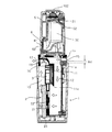
図3及び図4は本実施の形態に係るイオン発生装置の正面図、図5は斜視図、図6は縦断面図である。本実施の形態に係るイオン発生装置は、タンクハウジング5及び送気口17の周囲を覆うキャップ7を取り付け可能になしてある。図3はイオン発生装置にキャップ7を取り付けた状態、図4はイオン発生装置からキャップ7を取り外した状態を示している。また、図6は図4のVI−VI線における断面図を示している。以下では、正面側を前とし、背面側を後ろとして説明を行う。
3 and 4 are front views of the ion generator according to the present embodiment, FIG. 5 is a perspective view, and FIG. 6 is a longitudinal sectional view. In the ion generator according to the present embodiment, a
本実施の形態に係るイオン発生装置は、有底筒状の送風ハウジング1の内部に、送風手段としての送風ファン2、及びイオン発生手段としてのプラズマクラスタユニット3を備えている。図6に示すように、送風ハウジング1の内部は、隔壁11により後側の吸気室12と前側の送気室13とに分割されている。吸気室12は、送風ハウジング1の後面側の上端付近に開設された吸気口15を介して外部に連通し、また送気室13は、送風ハウジング1の前面側の上端付近に開設された送気口17を介して外部に連通している。吸気室12及び送気室13は、隔壁11の下部に設けた開口11aを経て相互に連通しており、吸気口15から送気口17に至る通気路を形成している。
The ion generator according to the present embodiment includes a blower fan 2 as a blower and a
送風ファン2は、羽根車21と、羽根車21を駆動するファンモータ22とを備えている。ファンモータ22は、送風ハウジング1の底部に固定されたケーシング23内に取り付けられ、隔壁11下部の開口11aに対向配置してある。送風ファン2の羽根車21は、ファンモータ22の駆動によって回転する。羽根車21が回転した場合、図6の白抜矢符で示すように、送風ハウジング1後側の上端付近に設けた吸気口15を経て、吸気室12の内部に外気が吸入される。吸気室12に吸入された外気は、吸気室12の内部を下向きに流れ、隔壁11下部の開口11aを経て羽根車21に吸い込まれ、上向きに方向を変えて送気室13の内部に導出される。そして、送気室13の末端に設けられた案内路16によって、送風方向が前記照射方向となるように変更されて、送気口17を経て外部に送り出される。
The blower fan 2 includes an
送風ファン2と送気口17との間には、プラス及びマイナスのイオンをそれぞれ同時的に発生させるプラズマクラスタユニット3が配設されている。プラズマクラスタユニット3を駆動している場合、送風ファン2から送気口17へ向かう通気路中にプラス及びマイナスのイオンが放出され、イオンを含んだ空気が送気口17より前記照射方向に送り出される。
Between the blower fan 2 and the
イオン発生装置は、送風ハウジング1の筒軸方向に連設され、送風ハウジング1の外径よりも少しだけ小さな外径を有するタンクハウジング5を備える。タンクハウジング5の背面には開口部51が設けられており、この開口部51を閉塞するように裏蓋52が着脱可能に取り付けられる。タンクハウジング5から裏蓋52を取り外すことによって、内部を開放できるように構成している。
The ion generator includes a
タンクハウジング5の内部には、水や化粧水などの液体を貯留するタンク50が着脱自在に装着される。タンク50内には、所定時間(例えば、30秒)のミストの発生を所定回数(例えば、5回)だけ行える量の液体が貯留される。ミストの噴射によりタンク50内の液体がなくなった場合、タンクハウジング5から取り出され、利用者によってタンク50内に液体が補充される。
Inside the
タンクハウジング5下部の前面側には、タンク50と連設するようにミスト発生器6を設けてある。ミスト発生器6は、公知の手法によりミストを発生させる装置であり、不図示の吸水材や給水管を用いてタンク50内の液体がミスト発生器6の内部に導入される。本実施の形態では、圧電素子を用いてタンク50から導入された液体を霧状化することにより、ミストを発生させる構成としている。すなわち、ミストSW102が押操作された場合、圧電素子に高周波信号を印加して、タンク50から導入された液体中に超音波を発生させることにより、ミスト発生器6内で液体を霧状化し、ミストを発生させる。
A
ミスト発生器6内で発生させたミストは、ノズル61を通じて噴射口62よりタンクハウジング5の外部へ噴射される。ミスト発生器6のノズル61は、イオンの照射方向と同方向を向くように方向が定められて設置されており、ノズル61の先端に開設された噴射口62よりミストを噴射することで、イオンと同方向にミストを噴射させることができる。
The mist generated in the
本実施の形態に係るイオン発生装置は、送風ハウジング1及びタンクハウジング5を筒軸方向に連設したものであり、タンクハウジング5は、送風ハウジング1よりも少しだけ小さな外径寸法を有する。
また、送風ハウジング1は、利用者の手により把持される把持部1aと、タンクハウジング5寄りに位置し、吸気口15及び送気口17が設けられる通気部1bとを有する。把持部1aは、通気部1bよりも大きな外径寸法を有している。すなわち、本実施の形態に係る送風ハウジング1は、タンクハウジング5寄りの部分に窪み(通気部1b)を有しており、この窪みに吸気口15及び送気口17を設けていることを特徴の1つとしている。
The ion generator according to the present embodiment has a
Further, the
この吸気口15は、通気部1bに沿って送風ハウジング1の周方向に複数個(例えば6個)設けられている。このため、利用者が送風ハウジング1を把持した際、偶然に吸気口15の1つを塞いでしまったとしても、残りの吸気口15を通じて外気を吸入することができ、通気路12における風量を確保することができる。
A plurality of (for example, six)
また、図6に示すように、送風ハウジング1の底面から吸気口15の下端までの高さを、送風ハウジング1の底面から送気口17の下端までの高さより少しだけ高くしている。送気口17がイオンの吹出口であることを利用者が知っている場合、その利用者は、送風ハウジング1の把持部1aを把持し、送気口17を塞ぐような持ち方はしないと考えられる。送気口17を塞がないようにイオン発生装置が把持された場合、送気口17より少しだけ上側(タンクハウジング5寄り)に位置する吸気口15は、利用者の手によって塞がれる可能性が少なくなり、必然的に吸気口15の周囲の空間を確保することができる。
この結果、吸気口15から送気口17に至る通気路中の風量を確保することが可能となる。プラズマクラスタユニット3から発生するイオンの量は、ユニットを通過する風量(風速)に依存するため、送風ハウジング1内の風量を確保することによって、照射するイオンの量を規定値以上に確保することができる。
Further, as shown in FIG. 6, the height from the bottom surface of the
As a result, it is possible to secure the air volume in the air passage from the
なお、本実施の形態では、通気部1bに吸気口15及び送気口17の双方を開設する構成としたが、通気部1bに吸気口15のみを開設し、通気部1bから少しだけ少し離隔した把持部1aの部分に送気口を開設する構成としてもよい。
In the present embodiment, both the
図7はイオン発生装置の制御系の構成を示すブロック図である。本実施の形態に係るイオン発生装置は、制御系の構成として、制御部100、電源SW101、ミストSW102、プラズマクラスタユニット3、モータ駆動部20、ファンモータ22、ミスト制御部60、ミスト発生器6を備える。
FIG. 7 is a block diagram showing the configuration of the control system of the ion generator. The ion generator according to the present embodiment includes a
制御部100は、CPU、ROM、RAMなどを備え、電源SW101及びミストSW102の入切りの状態に応じて、プラズマクラスタユニット3、モータ駆動部20、ミスト制御部60の動作を制御する。
具体的には、電源SW101の入操作を検知した場合、制御部100は、プラズマクラスタユニット3及びモータ駆動部20に対して動作開始信号を送出し、プラズマクラスタユニット3よりイオンを発生させると共に、送風ファン2を駆動して送風ハウジング1内に空気流を発生させる制御を行う。また、ミストSW102の入操作を検知した場合、制御部100は、ミスト制御部60に対して動作開始信号を送出し、所定時間だけミストを発生させる制御を行う。
The
Specifically, when the turning-on operation of the
プラズマクラスタユニット3は、パルス発生回路、トランス、放電電極31b,32b(図9を参照)などを備え、制御部100からの動作開始信号を受信した場合、放電電極31b,32bに交流波形またはインパルス波形からなる電圧を印加することによって、後述するようなイオンを発生させる。
The
モータ駆動部20は、送風ファン2のファンモータ22を駆動するための駆動回路である。本実施の形態では、イオン発生装置が手持ちで使用されているか、クレードルに載置して使用されているかによって、ファンモータ22の回転数を異ならせるようにしている。イオン発生装置が手持ちで使用され、内蔵バッテリからの電源供給を受けて動作している場合、制御部100は、第1の回転数(回転速度)でファンモータ22を駆動すべく制御信号をモータ駆動部20に送出する。また、イオン発生装置がクレードルに載置され、商用電源からの電源供給を受けて動作している場合、第1の回転数より高い第2の回転数(回転速度)でファンモータ22を駆動すべく制御信号をモータ駆動部20に送出する。
The
モータ駆動部20は、制御部100からの指示に応じた回転数でファンモータ22を駆動する。これにより、クレードルに載置して使用している場合には、手持ちで使用している場合と比較して風速を上げることができるので、イオンの到達距離を延ばすことができる。
The
ミスト制御部60は、タイマ等を有し、制御部100からの動作開始信号を受信した場合、ミスト発生器6によるミストの生成及び噴射を開始させると共に、ミストの生成及び噴射を開始してからの経過時間をタイマにより計時する。そして、経過時間が所定時間(例えば、30秒)に達した場合、ミスト制御部60は、ミスト発生器6によるミストの生成及び噴射を停止させる制御を行う。
When the
図8はイオン発生装置の動作手順を説明するフローチャートである。イオン発生装置の電源SW101が入操作(オン)された場合(ステップS11)、制御部100は、プラズマクラスタユニット3及びモータ駆動部20に対して駆動開始信号を送出し、プラズマクラスタユニット3及びモータ駆動部20を駆動する(ステップS12)。制御部100は、内蔵バッテリからの電源供給を受けている場合、第1回転数でファンモータ22を駆動するようにモータ駆動部20に制御信号を与え、商用電源からの電源供給を受けている場合、第2回転数でファンモータ22を駆動するようにモータ駆動部20に制御信号を与える。
FIG. 8 is a flowchart for explaining the operation procedure of the ion generator. When the
次いで、制御部100は、ミストSW102が入操作(オン)されたか否かを判断する(ステップS13)。ミストSW102が入操作されていない場合(S13:NO)、制御部100は、処理をステップS18に移行させる。
Next, the
ミストSW102が入操作されたと判断した場合(S13:YES)、制御部100は、ミスト制御部60に対して動作開始信号を送出し、ミスト発生器6を駆動する(ステップS14)。
制御部100から送出された動作開始信号を受信した場合、ミスト制御部60は、ミスト発生器6によるミストの生成及び噴射を開始させると共に、内蔵タイマを作動させて経過時間の計時を開始する(ステップS15)。
When it is determined that the
When the operation start signal sent from the
次いで、ミスト制御部60は、計時を開始してから所定時間が経過したか否かを判断する(ステップS16)。所定時間が経過していないと判断した場合(S16:NO)、ミスト制御部60は、所定時間が経過するまで待機する。
所定時間が経過したと判断した場合(S16:YES)、ミスト制御部60は、ミスト発生器6によるミストの生成及び噴射を停止させる(ステップS17)。
Next, the
When it is determined that the predetermined time has elapsed (S16: YES), the
次いで、制御部100は、電源SW101が切操作(オフ)されたか否かを判断する(ステップS18)。電源SW101が切操作されていない場合(S18:NO)、制御部100は、処理をステップS13へ戻す。
電源SW101が切操作されたと判断した場合(S18:YES)、制御部100は、プラズマクラスタユニット3及びモータ駆動部20に対して動作停止信号を送出し、プラズマクラスタユニット3及びファンモータ22の駆動を停止する(ステップS19)。
Next, the
If it is determined that the
以下、本実施の形態に係るイオン発生装置が照射するイオン及びミストによる作用について説明する。
図9はプラズマクラスタユニット3及び送気口17の位置関係を示す図である。プラズマクラスタユニット3は、送風ハウジング1内の送気室13に面する側が開口した2つの凹部31a,32aを有し、これらの凹部31a,32a内にはそれぞれ針状の放電電極31b,32bが立設されている。
Hereinafter, the effect | action by the ion and mist which the ion generator which concerns on this Embodiment irradiates is demonstrated.
FIG. 9 is a diagram showing the positional relationship between the
プラズマクラスタユニット3には、パルス発生回路、トランスなどが内蔵されていて、放電電極31b,32bには、交流波形またはインパルス波形からなる電圧が印加される。一方の放電電極31bには正電圧が印加され、電離により発生するイオンが空気中の水分と結合して、主として、H+ (H2 O)m (mは0又は任意の自然数)の組成からなるプラスイオン(クラスタイオン)が形成される。また、他方の放電電極32bには負電圧が印加され、電離により発生するイオンが空気中の水分と結合して、主として、O2 -(H2 O)n (nは0又は任意の自然数)の組成からなるマイナスイオン(クラスタイオン)が形成される。
The
本実施の形態では、送気口17からのイオン濃度が10万個/cm3 程度となるように、放電電極31b,32bに印加する電圧の大きさ及びパルス周期を調整している。
In the present embodiment, the magnitude of the voltage applied to the
前述したように、プラズマクラスタユニット3では、プラスイオン及びマイナスイオンを各別に発生させている。送風ハウジング1の上端付近に設けた送気口17は、2つの放電電極31b,32bの間隔よりも横方向に長い開口を形成している。また、送気口17には、プラスイオンを含む空気とマイナスイオンを含む空気とを区画する区画壁18を設けている。このため、送気口17からは、プラスイオンを含む空気とマイナスイオンを含む空気とが分離した状態で前記照射方向へ送り出され、プラスイオン及びマイナスイオンは、その多くが送気口17付近で結合することなく、照射部位である肌表面に到達し易くなる。
As described above, the
図10はイオン及びミストの照射方向を示す模式図である。本実施の形態では、イオンの照射と共に、イオンの照射方向と同方向にミストを噴射することが可能である。ミストは、数μm程度の大きさの粒子により構成されており、空気中を浮遊する間に重力の作用を受けて鉛直下方に少しだけ流下する。一方のイオンは、比較的軽いナノサイズの粒子であるから、空気中を浮遊する間にその高度が若干上昇する。そのため、送気口17及び噴射口62から照射方向に適宜の距離を隔てた領域でイオン及びミストが混在した状態となる。
したがって、送風ファン2による風速及び噴射口62からのミストの噴射速度を調整しておくことにより、照射部位である肌表面付近にてイオン及びミストを混在させた状態を作り出すことができる。
FIG. 10 is a schematic diagram showing the irradiation direction of ions and mist. In the present embodiment, it is possible to inject mist in the same direction as the ion irradiation direction together with the ion irradiation. The mist is composed of particles having a size of about several μm, and flows down slightly in the vertical direction under the action of gravity while floating in the air. Since one ion is a relatively light nano-sized particle, its altitude increases slightly while floating in the air. For this reason, ions and mist are mixed in a region separated from the
Therefore, by adjusting the wind speed by the blower fan 2 and the mist ejection speed from the
イオン発生装置から送り出されたプラスイオン及びマイナスイオンは、照射部位である肌表面において、以下のような反応を起こす。 The positive ions and negative ions sent out from the ion generator cause the following reaction on the skin surface that is the irradiation site.
(1)H+ (H2 O)m +O2 -(H2 O)n →・OH+1/2O2 +(m+n)H2 O
(2)H+ (H2 O)m +H+ (H2 O)m’+O2 -(H2 O)n +O2 -(H2 O)n’→2・OH+O2 +(m+m’+n+n’)H2 O
(3)H+ (H2 O)m +H+ (H2 O)m’+O2 -(H2 O)n +O2 -(H2 O)n’→ H2 O2 +O2 +(m+m’+n+n’)H2 O
(1) H + (H 2 O) m + O 2 − (H 2 O) n → OH + 1/2 O 2 + (m + n) H 2 O
(2) H + (H 2 O) m + H + (H 2 O) m ′ + O 2 − (H 2 O) n + O 2 − (H 2 O) n ′ → 2.OH + O 2 + (m + m ′ + n + n ′ ) H 2 O
(3) H + (H 2 O) m + H + (H 2 O) m ′ + O 2 − (H 2 O) n + O 2 − (H 2 O) n ′ → H 2 O 2 + O 2 + (m + m ′) + N + n ′) H 2 O
すなわち、H+ イオン及びO2 -イオンを同時的に肌表面に照射することにより、肌表面に・OH基が付着し、肌表面が局所的に親水化されて水分子が付着しやすい状態となる。特に、本実施の形態では、イオンの照射と共に、イオンの照射方向と同方向にミストを噴射することが可能であるため、肌表面に付着した・OH基の周囲に十分な水分子を供給することができ、より効率的にナノサイズの水分子を生成させることができ、この結果、水分子が肌に浸透しやすくなり、肌水分量を増加させることができるという効果を奏する。 That is, by simultaneously irradiating the skin surface with H + ions and O 2 − ions, the OH group adheres to the skin surface, the skin surface is locally hydrophilized, and water molecules are likely to adhere. Become. In particular, in the present embodiment, it is possible to spray mist in the same direction as the ion irradiation direction together with the ion irradiation, so that sufficient water molecules are supplied around the OH group attached to the skin surface. It is possible to generate nano-sized water molecules more efficiently, and as a result, the water molecules can easily penetrate into the skin, and the skin moisture content can be increased.
1 送風ハウジング
2 送風ファン
3 プラズマクラスタユニット
5 タンクハウジング
6 ミスト発生器
15 吸気口
17 送気口
DESCRIPTION OF
Claims (4)
液体を貯留するタンクと、該タンクに貯留された液体を霧状化する霧状化手段と、該霧状化手段により霧状化した液体を外部へ噴射する噴射手段とを収容し、前記送風ハウジングの上側に連接されたタンクハウジングと
を備え、
前記送風ハウジングの上端部の幅寸法を中央部の幅寸法より小さくして、前記送風ハウジングの上端部における外周面の全周に亘って段差面を形成してあり、
前記段差面に前記吸気口を設けてある
ことを特徴とするイオン発生装置。 A blowing means having an intake port and an air supply port, provided in the middle of an air passage communicating the intake port and the air supply port, and generating an air flow from the intake port to the air supply port; Containing an ion generating means for generating ions and negative ions separately and releasing them to the air passage, and a bottomed cylindrical air blowing housing gripped by a user;
A tank for storing liquid ; an atomizing means for atomizing the liquid stored in the tank; and an injection means for injecting the liquid atomized by the atomizing means to the outside. and a tank housing which is connected to the upper side of the housing,
The width dimension of the upper end portion of the blower housing is made smaller than the width dimension of the central portion, and a step surface is formed over the entire outer circumference of the upper end portion of the blower housing ,
The ion generator is characterized in that the air inlet is provided on the stepped surface .
Priority Applications (3)
| Application Number | Priority Date | Filing Date | Title |
|---|---|---|---|
| JP2012204739A JP5955174B2 (en) | 2012-09-18 | 2012-09-18 | Ion generator |
| CN201390000726.4U CN204424687U (en) | 2012-09-18 | 2013-09-12 | Ion generating device |
| PCT/JP2013/074645 WO2014045992A1 (en) | 2012-09-18 | 2013-09-12 | Ion generating device |
Applications Claiming Priority (1)
| Application Number | Priority Date | Filing Date | Title |
|---|---|---|---|
| JP2012204739A JP5955174B2 (en) | 2012-09-18 | 2012-09-18 | Ion generator |
Publications (2)
| Publication Number | Publication Date |
|---|---|
| JP2014057734A JP2014057734A (en) | 2014-04-03 |
| JP5955174B2 true JP5955174B2 (en) | 2016-07-20 |
Family
ID=50614791
Family Applications (1)
| Application Number | Title | Priority Date | Filing Date |
|---|---|---|---|
| JP2012204739A Expired - Fee Related JP5955174B2 (en) | 2012-09-18 | 2012-09-18 | Ion generator |
Country Status (1)
| Country | Link |
|---|---|
| JP (1) | JP5955174B2 (en) |
Families Citing this family (2)
| Publication number | Priority date | Publication date | Assignee | Title |
|---|---|---|---|---|
| KR101686783B1 (en) * | 2014-12-15 | 2016-12-15 | (주)와이에스 | Portable Skin Beauty Machine using Cold Plasma |
| KR101713697B1 (en) * | 2015-09-22 | 2017-03-09 | 광운대학교 산학협력단 | Hydroxy Radical Generation Apparatus Using Atmosphere Pressure Plasma |
Family Cites Families (5)
| Publication number | Priority date | Publication date | Assignee | Title |
|---|---|---|---|---|
| JP2003159305A (en) * | 2001-09-13 | 2003-06-03 | Matsushita Electric Works Ltd | Skin care device |
| JP2010172875A (en) * | 2009-02-02 | 2010-08-12 | Panasonic Electric Works Co Ltd | Mist generator |
| JP4790068B2 (en) * | 2009-10-09 | 2011-10-12 | シャープ株式会社 | Method and beauty device for increasing moisture content on skin surface and improving moisture retention function of dermis |
| JP5117525B2 (en) * | 2010-03-26 | 2013-01-16 | パナソニック株式会社 | Mist generator and beauty device |
| JP3171938U (en) * | 2011-09-13 | 2011-11-24 | クルールラボ株式会社 | Portable beauty device |
-
2012
- 2012-09-18 JP JP2012204739A patent/JP5955174B2/en not_active Expired - Fee Related
Also Published As
| Publication number | Publication date |
|---|---|
| JP2014057734A (en) | 2014-04-03 |
Similar Documents
| Publication | Publication Date | Title |
|---|---|---|
| JP3214558U (en) | air purifier | |
| JP3140444U (en) | Portable water supply | |
| JP5988796B2 (en) | Ion generation system | |
| JP5366027B2 (en) | air purifier | |
| JP6370185B2 (en) | Mist generator | |
| EP3153131B1 (en) | Teeth bleaching apparatus | |
| RU2014140192A (en) | HUMIDIFIER INSTALLATION | |
| JP2006026022A (en) | Steam generator for beauty art | |
| JP6156357B2 (en) | Humidifier | |
| KR100877000B1 (en) | Metal filter and portable moisture supply apparatus for using the same | |
| EP2377421A1 (en) | Functional beauty applicator using cold steam | |
| JP5955174B2 (en) | Ion generator | |
| JP2009136303A (en) | Hair dryer | |
| WO2010137503A1 (en) | Mist generating device | |
| JP6465614B2 (en) | Mist generator | |
| JP5863608B2 (en) | Ion generator | |
| WO2010087486A1 (en) | Mist generation device | |
| WO2014045992A1 (en) | Ion generating device | |
| JP2014057737A (en) | Ion generator | |
| WO2014042173A1 (en) | Moisturizing device and electric apparatus loaded with same, and moisturizing method | |
| JP2004148107A (en) | Lustrous skin device and treatment device | |
| KR20170141339A (en) | Plasma toothbrush | |
| JP5385958B2 (en) | Facial massager | |
| JP2010187761A (en) | Mist generator and cosmetic device | |
| JP2007037969A (en) | Cosmetic apparatus |
Legal Events
| Date | Code | Title | Description |
|---|---|---|---|
| A621 | Written request for application examination |
Free format text: JAPANESE INTERMEDIATE CODE: A621 Effective date: 20150318 |
|
| A131 | Notification of reasons for refusal |
Free format text: JAPANESE INTERMEDIATE CODE: A131 Effective date: 20160105 |
|
| A521 | Request for written amendment filed |
Free format text: JAPANESE INTERMEDIATE CODE: A523 Effective date: 20160201 |
|
| TRDD | Decision of grant or rejection written | ||
| A01 | Written decision to grant a patent or to grant a registration (utility model) |
Free format text: JAPANESE INTERMEDIATE CODE: A01 Effective date: 20160524 |
|
| A61 | First payment of annual fees (during grant procedure) |
Free format text: JAPANESE INTERMEDIATE CODE: A61 Effective date: 20160614 |
|
| R150 | Certificate of patent or registration of utility model |
Ref document number: 5955174 Country of ref document: JP Free format text: JAPANESE INTERMEDIATE CODE: R150 |
|
| LAPS | Cancellation because of no payment of annual fees |