JP5952584B2 - Refrigerator - Google Patents
Refrigerator Download PDFInfo
- Publication number
- JP5952584B2 JP5952584B2 JP2012033619A JP2012033619A JP5952584B2 JP 5952584 B2 JP5952584 B2 JP 5952584B2 JP 2012033619 A JP2012033619 A JP 2012033619A JP 2012033619 A JP2012033619 A JP 2012033619A JP 5952584 B2 JP5952584 B2 JP 5952584B2
- Authority
- JP
- Japan
- Prior art keywords
- machine room
- hose
- drain hose
- plate
- drain
- Prior art date
- Legal status (The legal status is an assumption and is not a legal conclusion. Google has not performed a legal analysis and makes no representation as to the accuracy of the status listed.)
- Expired - Fee Related
Links
- 238000001816 cooling Methods 0.000 claims description 66
- 238000005057 refrigeration Methods 0.000 claims description 31
- 238000003860 storage Methods 0.000 claims description 27
- XLYOFNOQVPJJNP-UHFFFAOYSA-N water Substances O XLYOFNOQVPJJNP-UHFFFAOYSA-N 0.000 claims description 26
- 238000009434 installation Methods 0.000 claims description 20
- 239000003507 refrigerant Substances 0.000 claims description 18
- 238000003780 insertion Methods 0.000 description 20
- 230000037431 insertion Effects 0.000 description 20
- 238000005516 engineering process Methods 0.000 description 11
- 238000009833 condensation Methods 0.000 description 8
- 230000005494 condensation Effects 0.000 description 8
- 239000011810 insulating material Substances 0.000 description 7
- 238000003825 pressing Methods 0.000 description 7
- 230000002265 prevention Effects 0.000 description 7
- 238000000034 method Methods 0.000 description 6
- 235000013305 food Nutrition 0.000 description 5
- 238000004140 cleaning Methods 0.000 description 4
- 230000003014 reinforcing effect Effects 0.000 description 3
- 238000005406 washing Methods 0.000 description 3
- 238000003466 welding Methods 0.000 description 3
- 210000000078 claw Anatomy 0.000 description 2
- 230000000694 effects Effects 0.000 description 2
- 238000001704 evaporation Methods 0.000 description 2
- 230000008020 evaporation Effects 0.000 description 2
- 238000007710 freezing Methods 0.000 description 2
- 230000008014 freezing Effects 0.000 description 2
- 238000004519 manufacturing process Methods 0.000 description 2
- 239000002184 metal Substances 0.000 description 2
- 229920003002 synthetic resin Polymers 0.000 description 2
- 239000000057 synthetic resin Substances 0.000 description 2
- 239000008399 tap water Substances 0.000 description 2
- 235000020679 tap water Nutrition 0.000 description 2
- 238000004065 wastewater treatment Methods 0.000 description 2
- 229910001335 Galvanized steel Inorganic materials 0.000 description 1
- 230000009471 action Effects 0.000 description 1
- 238000005452 bending Methods 0.000 description 1
- 230000008901 benefit Effects 0.000 description 1
- 235000008429 bread Nutrition 0.000 description 1
- 238000010411 cooking Methods 0.000 description 1
- 238000009826 distribution Methods 0.000 description 1
- 238000005315 distribution function Methods 0.000 description 1
- 239000006260 foam Substances 0.000 description 1
- 239000008397 galvanized steel Substances 0.000 description 1
- 230000005484 gravity Effects 0.000 description 1
- 238000009413 insulation Methods 0.000 description 1
- 239000000463 material Substances 0.000 description 1
- 230000002093 peripheral effect Effects 0.000 description 1
- 230000008569 process Effects 0.000 description 1
- 239000002994 raw material Substances 0.000 description 1
- 230000009467 reduction Effects 0.000 description 1
- 125000006850 spacer group Chemical group 0.000 description 1
Images


Description
本発明は、急速冷却庫等の冷却庫に関する。 The present invention relates to a refrigerator such as a rapid refrigerator.
従来、急速冷却庫の一例として、特許文献1に記載されたものが知られている。このものは、内部が被冷却物を収納する収納室とされ、かつ同収納室の一側面側に冷却器と冷却ファンとを有する冷却ユニットが配設された冷凍庫本体の下面に機械室が設けられ、同機械室内には、圧縮機、空冷式の凝縮器等からなる冷凍装置が装備されて冷却器と冷媒配管により循環接続された構造になり、冷凍装置と冷却ファンを駆動することにより、冷却器で生成された冷気が収納室に循環供給されて、食品が急速冷却されるようになっている。 Conventionally, what was described in patent document 1 is known as an example of a rapid cooling cabinet. This machine room is provided in the lower surface of the freezer body in which the inside is a storage room for storing the object to be cooled, and a cooling unit having a cooler and a cooling fan is provided on one side of the storage room. The machine room is equipped with a refrigeration system comprising a compressor, an air-cooled condenser, etc., and is connected in a circulating manner by a cooler and a refrigerant pipe. By driving the refrigeration system and the cooling fan, The cold air generated by the cooler is circulated and supplied to the storage chamber so that the food is rapidly cooled.
一方、この種の急速冷却庫では、食材の付着等で庫内が汚れやすいという事情があり、また冷却ユニットに配された冷却器についても、食材から発生したガスが付着して腐食するおそれがあるため、適宜にホース等から水道水を掛けて水洗いされる。そして、洗浄に供した後の排水を処理するために、収納室の底壁における手前側の隅部等の適宜位置に排水孔を開口し、同排水孔に接続されたドレンホースを機械室の天井部を通して背面等から外部に導出した手段が講じられている。 On the other hand, in this type of rapid cooling cabinet, there is a situation that the inside of the cabinet is easily soiled due to adhesion of foodstuffs, etc. Also, the gas generated from the foodstuff may adhere to the cooler arranged in the cooling unit and corrode. For this reason, the water is appropriately washed with tap water from a hose or the like. And in order to treat the drainage after being used for cleaning, drainage holes are opened at appropriate positions such as the front corners of the bottom wall of the storage chamber, and the drain hose connected to the drainage hole is connected to the machine room. Means taken out from the back or the like through the ceiling are taken.
上記のような排水処理手段が講じられている場合、当該急速冷却庫では以下のような問題がある。すなわち急速冷却庫では庫内が−数10℃に冷却され、その冷熱が機械室に配管されたドレンホースにも伝導されてドレンホースが低温となり、一方、機械室内は冷凍装置(凝縮器)を冷却した後の排熱が流通する等で高温雰囲気にあるために、ドレンホースに結露が生じ、その結露水が機械室内に滴下して、配設された電気部品等に降り懸かるおそれがあった。
本発明は上記のような事情に基づいて完成されたものであって、その目的は、ドレンホースへの結露水が機械室内に滴下することを防止するところにある。
When the waste water treatment means as described above is taken, the rapid refrigerator has the following problems. That is, in the rapid cooling chamber, the interior is cooled to −several tens of degrees Celsius, and the cold heat is also transmitted to the drain hose piped in the machine room, and the drain hose becomes low temperature. Since the exhaust heat after cooling is in a high-temperature atmosphere due to circulation, condensation may occur in the drain hose, and the condensed water may drip into the machine room and fall on the installed electrical parts, etc. .
The present invention has been completed based on the above circumstances, and an object thereof is to prevent the dew condensation water on the drain hose from dripping into the machine room.
本発明は、内部が被冷却物を収納する収納室とされ、かつ同収納室の一側面側に冷却器と冷却ファンとを有する冷却ユニットが配設された冷却庫本体の下面には機械室が設けられ、同機械室内には、圧縮機、空冷式の凝縮器等からなる冷凍装置が装備されて前記冷却器と冷媒配管により循環接続され、前記冷凍装置と前記冷却ファンを駆動することにより、前記冷却器で生成された冷気が前記収納室に循環供給されるとともに、前記冷却器本体の庫内底面には排水孔が開口されて、同排水孔に接続されたドレンホースが前記機械室の天井部を通って外部に導出されている冷却庫において、前記機械室の天井面には、前記ドレンホースを挿通する溝形をなすホースカバーが装着され、かつ前記ホースカバーの両側面には、前記機械室内の流通空気が通ることを許容する開口が形成されているところに特徴を有する。 The present invention provides a machine room on the lower surface of a refrigerator main body in which a cooling chamber having a cooling unit and a cooling fan is disposed on one side of the storage chamber. In the machine room, a refrigeration apparatus comprising a compressor, an air-cooled condenser, and the like is installed, and is circulated and connected by the cooler and a refrigerant pipe, and the refrigeration apparatus and the cooling fan are driven. The cool air generated by the cooler is circulated and supplied to the storage chamber, and a drain hole is opened on the bottom surface of the cooler body, and a drain hose connected to the drain hole is connected to the machine chamber. In the refrigerator led out to the outside through the ceiling of the machine room, a hose cover having a groove shape through which the drain hose is inserted is mounted on the ceiling surface of the machine room, and on both side surfaces of the hose cover , Distribution air in the machine room Characterized in place are open to allow it is formed that passes.
ドレンホースに結露して結露水が滴下しても、ホースカバーの溝底で受けられて機械室内に滴下することが防止される。一方、冷凍装置の運転中は、庫外から取り込まれた冷却用空気が凝縮器に当てられてこれを冷却し、冷却に供したのちの排熱が機械室内を通って外部に排出されるが、仮に同排熱がホースカバーで遮られたとしても、側面の開口を通って良好に流通し、凝縮器が効率良く冷却される。その結果、冷凍装置の冷凍能力は確保される。 Even if condensation is condensed on the drain hose and the condensed water is dripped, it is received at the groove bottom of the hose cover and prevented from dripping into the machine room. On the other hand, during the operation of the refrigeration system, the cooling air taken from the outside is applied to the condenser to cool it, and the exhaust heat after cooling is exhausted outside through the machine room. Even if the exhaust heat is blocked by the hose cover, it can be circulated well through the opening on the side surface, and the condenser is efficiently cooled. As a result, the refrigeration capacity of the refrigeration apparatus is ensured.
また、以下のような構成としてもよい。
(1)前記冷却庫本体が、前面開口でかつ同前面開口に開閉扉が装着された構造であって、同冷却庫本体内には、間口方向の一側に前記収納室が、他側に前記冷却ユニットが設置された設置室が設けられ、前記機械室内には、間口方向における前記設置室が設けられた側と対応する側に、前記冷凍装置が前記空冷式の凝縮器と前記圧縮機とを前後に並べた形態で設置され、かつ前記機械室の前面における前記冷凍装置の前方に対応する領域に外気の吸気口が、同機械室における前記冷凍装置の設置側とは反対側の側面に排熱の排気口が形成されているとともに、前記収納室の底面における前記設置室とは反対側の端縁側でかつ手前側の隅部に最深部が形成されて、同最深部に前記排水孔が形成され、前記排水孔に一端が接続された前記ドレンホースの他端が、前記機械室における前記冷凍装置の設置側とは反対側のスペースの天井部を後方に向けて配管され、前記ドレンホースにおける前記機械室内での配管部分のほぼ全長が、前記ホースカバーに挿通されている。
The following configuration may also be used.
(1) The cooling body has a structure having a front opening and an opening / closing door attached to the front opening, and the storage room is located on one side of the frontage direction on the other side. An installation chamber in which the cooling unit is installed is provided, and in the machine room, the refrigeration apparatus is provided with the air-cooled condenser and the compressor on the side corresponding to the side in which the installation chamber is provided in the frontage direction. And a side surface of the machine room opposite to the installation side of the refrigeration apparatus, where the outside air intake port is located in a region corresponding to the front of the refrigeration apparatus on the front surface of the machine room. And an exhaust port for exhaust heat is formed on the bottom surface of the storage chamber, the deepest portion is formed at the corner on the side opposite to the installation chamber and on the near side, and the drainage is formed at the deepest portion. The drain having a hole and having one end connected to the drain hole The other end of the pipe is piped with the ceiling portion of the space opposite to the installation side of the refrigeration apparatus in the machine room facing rearward, and the substantially total length of the pipe part in the machine room in the drain hose is The hose cover is inserted.
庫内を洗浄水で洗浄した場合、洗浄後の排水は収納室の底面の最深部に流下したのち、排水孔からドレンホースを通って排出される。機械室内においてドレンホースに結露して結露水が滴下しても、ホースカバーの底面で受けられる。冷却運転時には、機械室の前面の吸気口から取り込まれた外気によって凝縮器が冷却され、冷却に供した後の排熱が機械室の側面の排気口から排出され、このとき排熱の一部がホースカバーで遮られる可能性があるが、側面の開口を通って良好に排出される。併せてホースカバーの底面に残った結露水が蒸発される。 When the inside of the cabinet is washed with washing water, the drainage after washing flows down to the deepest part of the bottom surface of the storage chamber and is then discharged from the drainage hole through the drain hose. Even if dew condensation drops on the drain hose in the machine room, it can be received at the bottom of the hose cover. During the cooling operation, the condenser is cooled by the outside air taken in from the intake port on the front of the machine room, and the exhaust heat after cooling is exhausted from the exhaust port on the side of the machine room. Can be blocked by the hose cover, but is well drained through the side openings. At the same time, the condensed water remaining on the bottom surface of the hose cover is evaporated.
(2)前記ホースカバーは、底板の両側縁から側板を立ち上げた溝形に形成され、前記両側板の上縁における長さ方向の両端部には、前記機械室の天井面に取り付けられる取付板が外側に直角曲げされた形態で形成されているとともに、前記両側板の長さ方向の中央部において、前記開口が上縁から所定深さ切り欠かれた形態で形成されている。
ホースカバーが、シンプルな構造でもって、機械室の天井面への簡単な取付機能と、取り付けられた後の排熱の流通機能とを確実に果たすことができる。
(2) The hose cover is formed in a groove shape in which the side plate is raised from both side edges of the bottom plate, and is attached to both ends of the upper edge of the side plates in the length direction on the ceiling surface of the machine room. The plate is formed in a shape bent at right angles to the outside, and the opening is formed in a shape that is cut out by a predetermined depth from the upper edge at the center portion in the length direction of the both side plates.
With a simple structure, the hose cover can reliably perform a simple attachment function to the ceiling surface of the machine room and a distribution function of exhaust heat after being attached.
(3)前記ホースカバーにおける前記ドレンホースの前記排水孔と接続された側の端部を収める側の端面が閉鎖されている。
ドレンホースは排水孔と接続された端部側ほど冷却されやすく、したがって同端部側ほど結露水が滴下しやすいといえるが、ホースカバーにおけるドレンホースの排水孔と接続された側の端部を収めた側の端面は閉鎖されているから、滴下した結露水が同端面から零れることが確実に阻止される。
(3) The end face of the hose cover on the side where the end of the drain hose connected to the drain hole is received is closed.
The drain hose is more likely to be cooled at the end connected to the drain hole, so that the condensed water is more likely to drip toward the end, but the end of the hose cover on the side connected to the drain hole of the drain hose Since the end surface on the storage side is closed, the dripped condensed water is reliably prevented from spilling from the end surface.
本発明によれば、冷凍装置の冷凍能力は確保したままで、ドレンホースへの結露水が機械室内に滴下することを防止できる。 ADVANTAGE OF THE INVENTION According to this invention, it can prevent that the dew condensation water to a drain hose dripping in a machine room, ensuring the freezing capacity of a freezing apparatus.
<実施形態>
以下、本発明の一実施形態を図1ないし図7に基づいて説明する。この実施形態では、急速冷却庫に適用した場合を例示している。
本実施形態の急速冷却庫は低背縦型であって、図1ないし図3に示すように、機械室40の上面に冷却庫本体10(以下、本体10)が載置され、機械室40の底面に配された脚11によって支持されている。
本体10は前面が開口されたやや横長の断熱箱体からなり、同本体10の前面開口部12には、断熱扉13が、正面から見た左側縁を中心として揺動開閉可能に装着されている。本体10の内部すなわち庫内では、図2に示すように、正面から見た右側の6割程度の領域が、食品の収納室15とされ、残りの左側の領域が、冷却ユニット20の設置室16となっている。
<Embodiment>
Hereinafter, an embodiment of the present invention will be described with reference to FIGS. In this embodiment, the case where it applies to a quick refrigerator is illustrated.
The rapid cooler of the present embodiment is a low profile vertical type, and as shown in FIGS. 1 to 3, a cooler main body 10 (hereinafter, main body 10) is placed on the upper surface of the
The
冷却ユニット20は、図5に示すように、冷却器21(蒸発器)と冷却ファン22とを組み付けてユニット化したものである。
冷却器21は、庫内の奥行方向に長いブロック状に形成されており、同冷却器21には、上面並びに手前側と奥側の面を覆うようにして、概ね門形をなす冷却器カバー25が装着されている。
冷却ファン22はファンケース27内に取り付けられている。ファンケース27は、冷却器カバー25の外形よりも一回り小さい背面側に開口した箱状に形成されており、その正面板の中心には円形のシュラウド28が形成されて、同シュラウド28内に冷却ファン22が装備されている。
このファンケース27が、上記した冷却器カバー25の正面側において、奥縁に設けられたヒンジ30を中心として揺動開閉可能に装着され、施錠装置31によって閉鎖状態に保持されるようになっている。
As shown in FIG. 5, the
The
The
The
冷却ユニット20は、庫内の左側の設置室16に設置される。冷却ユニット20は、図5に示すように、その手前側と奥側の面が、それぞれ閉鎖された断熱扉13の裏面と設置室16の奥壁16Aとの間に所定間隔を開け、かつ正面視で左側面が設置室16の左側壁16Bとの間に所定間隔を開けた形態で配され、図2に示すように、冷却器カバー25の上面に設けられた取付板33が設置室16の天井壁16Cにねじ止めにより固定されるとともに、冷却器カバー25の背面の下縁部と、設置室16の左側壁16Bとの間にスペーサ板を兼ねた取付板34が渡されることで、定位置に取り付けられている。
The
冷却ユニット20において、ファンケース27の閉鎖時には、同ファンケース27内に取り付けられた冷却ファン22が、冷却器21の正面中央部の直前に位置し、施錠装置31を解錠すると、ファンケース27はヒンジ30を中心として図5の反時計回り方向に90度揺動して開放可能となっている。ファンケース27の開放は、後記するように、庫内を水洗いするときと併せて、冷却ユニット20の内部を水洗いする場合に利用される。
冷却ユニット20の下面側には、冷却器21からの除霜水を受けて溜めるドレンパン36が、手前側からの出し入れ可能に装着されている。
In the
On the lower surface side of the cooling
庫内右側の収納室15には、トレイT(図5参照)が複数段(最大5段)に亘り、前方から出し入れされて収納可能となっている。そのため、収納室15の左右の側面となる冷却ユニット20におけるファンケース27の正面板と、収納室15の右側壁15Bとに、一対のトレイ受け38が対向して着脱可能に取り付けられるようになっている。トレイTとしては、ベーカリ用天板やホテルパンが挙げられる。
In the
次に機械室40を説明する。機械室40は、図7に示すように、その背面40Rが、冷却庫本体10のそれよりも所定寸法前方に入り込んでいる。機械室40の前面にはフロントパネル41が着脱可能に張られており、図1に示すように、同フロントパネル41における左側の略3/4の領域に吸気口42が形成されている。機械室40の内部には冷凍装置43が設置されており、主には吸気口42の直後に凝縮器ファン44Aが装備された凝縮器44(図2の鎖線)が、その後方に圧縮機45が配されて引き出し可能な載置台46上に設置されている。この冷凍装置43と、上記した冷却ユニット20に設けられた冷却器21とが冷媒配管47によって循環接続され、冷凍回路が構成されている。機械室40における背面40Rと左右の側面には、排熱等の排気口48が形成されている。
また、載置台46上における正面視で右側縁に寄った位置には、奥行方向に長い電装箱49が出し入れ可能に設置されている。電装箱49は、機械室40内の高さの2/3程度の高さ寸法に抑えられ、したがって電装箱49の上方に、後記するドレンホース58の配管スペース50が設けられている。
Next, the
In addition, an
続いて、庫内の排水処理部分の構造について説明する。庫内の底面52は、上記した前面開口部12の下端面12Aよりも下方に凹み形成されており、かつ正面視で右側手前の隅部が最深部53となるような傾斜面として形成されている。
この底面52の最深部53には排水孔体55が装着されている。同排水孔体55は、底壁を貫通して、機械室40内の上記した配管スペース50の天井面50Aにおける手前側の位置から下方に突出するようにして装着されている。
図7に示すように、排水孔体55の下方突出端には、エルボ56を介して、ドレンホース58の一端が接続され、その他端が、配管スペース50の天井面50Aに沿うように背面側に向けて配管され、同配管スペース50の背面から突出して垂下するようになっている。
なお、排水孔体55は常には栓をして塞がれており、適宜に栓を外して開放されるようになっている。
Then, the structure of the waste water treatment part in a store | warehouse | chamber is demonstrated. The
A
As shown in FIG. 7, one end of a
The
さて、上記したドレンホース58は、その配管スペース50内に配管されたほぼ全長にわたって、ホースカバー60に挿通されている。
このホースカバー60は、図6にも示すように、亜鉛メッキ鋼板等の金属板を素材として形成され、底板61の左右両側縁から側板62を立ち上げた溝形に形成され、手前の開口には前板63が張られている。同ホースカバー60は、機械室40の奥行よりも少し小さい長さ寸法と、ドレンホース58の直径の2倍程度の深さ寸法を有している。
Now, the
As shown in FIG. 6, the
ホースカバー60における左右の側板62では、長さ方向の中央部における大部分の領域において、上縁から所定深さ(全深さの2/3程度)切り欠かれた形態で開口64が形成されている。
より詳細には、各側板62における開口64が形成された領域よりも手前側の端部領域の方が、奥側の端部領域よりも2倍以上程度長く取られており、手前側端部62Aと奥側端部62Bの上縁には、それぞれ外向きに直角曲げされた取付板65A,65Bが形成されている。各取付板65A,65Bには、ねじの挿通孔66が開口されている。
In the left and
More specifically, the end region on the near side is longer than the end region on the near side than the region where the
上記したホースカバー60は、排水孔体55の配設位置の直下位置から背面側に真直に延出した形態で、配管スペース50の天井面50Aに当てられ、手前側の左右の取付板65A及び奥側の左右の取付板65Bをそれぞれねじ止めすることによって固定されている。
このようにホースカバー60が取り付けられると、排水孔体55の下方突出端からこれと接続されたドレンホース58の一端が、前板63で塞がれたホースカバー60の手前側の端部内に収められ、背面側に向けて配管されたドレンホース58がホースカバー60内に挿通されたのち、奥側の端面から突出してさらには上記のように配管スペース50の背面から突出するようになっている。なお、ドレンホース58の背面突出端は、さらにホースが接続される等で、適宜の排水箇所に導かれている。
The above-described
When the
続いて、本実施形態の作用を説明する。当該急速冷却庫は、加熱調理後の食品を短時間で冷却することに用いられる。
調理後の食品はトレイTに入れられ、左右のトレイ受け38で受けられて最大5段にわたって収納室15内に収納される。断熱扉13を閉じたのち急速冷却運転がなされ、すなわち冷凍装置43(圧縮機45)と冷却ファン22とが運転されると、図5の矢線に示すように、収納室15の空気がファンケース27のシュラウド28を通って冷却ユニット20内に吸引されて冷却器21を通過する間に冷気が生成され、冷却ユニット20の背面側に吹き出された冷気が、庫内の左側壁16Bに当たって手前と奥に分かれて同冷却ユニット20の手前側と奥側の側面に回り込んだのち、収納室15に送り込まれるといった循環流を生じ、これによりトレイTに入れられた食品が急速冷却される。
Then, the effect | action of this embodiment is demonstrated. The rapid cooling box is used for cooling food after cooking in a short time.
The cooked food is placed in the tray T, received by the left and
この間、凝縮器44の後面に配された凝縮器ファン44Aが併せて駆動されることにより、機械室40のフロントパネル41の吸気口42から外気が吸い込まれて、凝縮器44を通過することにより凝縮器44が冷却され、冷却に供した後の排熱は、機械室40の背面や左右の側面に設けられた排気口48を通して外部に排出される。
所定時間が経過したら冷却運転が停止され、断熱扉13を開いたのちトレイTが庫外に出される。
During this time, the
When the predetermined time has elapsed, the cooling operation is stopped, and after the
本体10内を清掃する場合は、ホース等で庫内の壁面に向けて水道水を掛けることで行われる。このとき排水孔体55は、栓を外して開けられる。また、冷却ユニット20内を併せて水洗いする場合は、両トレイ受け38を外して庫外に出したのち、冷却ユニット20の施錠装置31を外して、ファンケース27をヒンジ30を中心にして奥壁15Aに向けて開く。そうすると、冷却器カバー25内の冷却器21並びに冷却ファン22が庫内に開放された状態となるから、直接に水を掛けて洗浄できる。
庫内等を洗浄したのちの排水は、収納室の底面52の最深部53に流下し、そこに設けられた排水孔体55から、機械室40の配管スペース50に配管されたドレンホース58を通り、適宜の排水箇所に排水される。
When cleaning the inside of the
The drainage after cleaning the inside of the storage chamber flows down to the
ここで急速冷却運転中では、庫内が−数10℃に冷却され、その冷熱が機械室40の配管スペース50に配管されたドレンホース58にも伝導されてドレンホース58が低温となり、一方、機械室40内は冷凍装置43(凝縮器44)を冷却した後の排熱が流通する等で高温雰囲気にあるために、ドレンホース58に結露が生じるおそれがあるが、仮に結露が生じて結露水が滴下しても、同ドレンホース58はホースカバー60に挿通されているから、結露水はホースカバー60の溝底で受けられ、その下方に設置された電装箱49に向けて滴下することが防止される。また、ドレンホース58は排水孔体55と接続された端部側ほど冷却されやすく、したがって同端部側ほど結露水が滴下しやすいといえるが、ホースカバー60におけるドレンホース58の排水孔体55と接続された側の端部を収めた手前側の端面は前板63で塞がれているから、同端面から結露水が零れることが確実に阻止される。
Here, during the rapid cooling operation, the interior is cooled to −several tens of degrees Celsius, and the cold heat is also transmitted to the
一方、冷凍装置43の運転中は、庫外から取り込まれた外気が凝縮器44に当てられてこれを冷却し、冷却に供したのちの排熱が機械室40内を通って外部に排出されるように作用する。ここで、当該急速冷却庫の配置の関係で、機械室40の左側面の排気口48が塞がれると、排熱は機械室40内を正面視で右側に流れて右側面の排気口48から排気される比重が高くなる。このとき同排熱は、配管スペース50にも流れてホースカバー60で遮られる可能性があるが、ホースカバー60には両側板62に開口64が切り欠き形成されているから、同開口64を通って排熱は良好に流通し、すなわち凝縮器44は効率良く冷却される。また、排熱が開口64を通ることで、ホースカバー60の溝底に残った結露水の蒸発が促進される。
On the other hand, during the operation of the
以上説明したように本実施形態によれば、機械室40の配管スペース50の天井面50Aに溝形をなすホースカバー60を取り付けて、同ホースカバー60内にドレンホース58を挿通して配管したから、仮にドレンホース58に結露が生じて結露水が滴下しても、ホースカバー60の溝底で受けられ、その下方に設置された電装箱49に向けて滴下することが防止される。また、ドレンホース58は排水孔体55と接続された手前の端部側ほど結露して結露水が滴下しやすいといえるが、ドレンホース58の手前の端部を収めたホースカバー60の手前側の端面は前板63で塞がれているから、同端面から結露水が零れることが確実に阻止される。
As described above, according to the present embodiment, the
また、冷却運転中は、凝縮器44が吸引された庫外空気で冷却されて冷却に供したのちの排熱が機械室40内を通って外部に排出されるように作用し、特に同排熱が機械室40の右側面の排気口48から排気される際には、同排熱は配管スペース50にも流れてホースカバー60で遮られる可能性があるが、ホースカバー60には両側板62に開口64が切り欠き形成されているから、同開口64を通って排熱は良好に流通する。そのため凝縮器44は効率良く冷却され、結果、冷凍装置43の冷凍能力は確保される。また、排熱が開口64を通ることで、ホースカバー60の溝底に残った結露水の蒸発が促進され、電装箱49へ降り懸かることがより確実に防止される。
Further, during the cooling operation, the
<関連技術>
上記実施形態に例示した急速冷却庫では他にも数々の工夫が凝らされており、以下にそれらについて関連技術として説明する。
(1)関連技術1は、図1に示されたところの、機械室40の前面の下縁に垂設されたショートサイクル防止板70に関する。このショートサイクル防止板70は、冷却運転中において、冷凍装置43を冷却した後の排熱が機械室40の背面側から吹き出され、背面の壁等に当たって機械室40の下面を手前側に流通し、機械室40のフロントパネル41の吸気口42から外気とともに吸い込まれるといったショートサイクルを防止することに機能するものである。
本実施形態の急速冷却庫は、機械室40の外底面の四隅にねじ込まれた脚11で設置面X(図9)上に支持されるが、機械室40の外底面と設置面Xとの間隔は微妙に異なる可能性がある。そのためショートサイクル防止板70は、高さ調節可能に装着されるようになっている。
<Related technologies>
The quick cooler illustrated in the above embodiment has many other ideas, which will be described below as related technologies.
(1) The related technique 1 relates to the short
The quick cooler of this embodiment is supported on the installation surface X (FIG. 9) by the
図8及び図9に示すように、ショートサイクル防止板70は、フルントパネルに設けられた全吸気口42の間口寸法よりも大きい長さ寸法を持った溝型に形成されており、その正面板71の両端部には、縦長のねじ73の挿通孔72が形成されている。
ショートサイクル防止板70は、正面板71の裏面が、機械室40の底板40Aに載せられた載置台46の手前の端縁に設けられた把手46Aに当てられ、両挿通孔72に通したねじ73が把手46Aに形成されたねじ孔74にねじ込まれて固定される。
ここで、ショートサイクル防止板70は、ねじ73を仮締めした状態で縦長の挿通孔72に沿って上下動させることにより高さ調節でき、図9の鎖線に示すように、ショートサイクル防止板70を設置面Xに当たるまで下げて取り付けることにより、ショートサイクルをより確実に防止することができる。
As shown in FIGS. 8 and 9, the short
The short
Here, the height of the short
(2)関連技術2は、機械室40の前面枠の増強構造に関する。図10に示すように、機械室40の前面枠を構成する上枠75は、水平板76の先端に鈎形に屈曲された屈曲板77が立ち上がり形成された形状であり、同水平板76の基端側が本体10の外底面の前縁に固定されている。
一方、機械室40に設置された凝縮器44の上面に張られた天板44Bの前縁が手前側に延出され、同延出端に取付板78が立ち上がり形成されている。
この取付板78の上縁部が上枠75の屈曲板77における垂直部77Aの前面下部に当てられ、例えば両端部がねじ79で止められて固定されている。なお、上枠の屈曲板77の水平部77Bには、フロントパネル41の上縁が引っ掛けられて、ねじで取り付けられるようになっている。
(2) The related technique 2 relates to a structure for reinforcing the front frame of the
On the other hand, the front edge of the
The upper edge of the mounting
このように、機械室40の前面枠の上枠75における大部分の長さ領域が、機械室40内に設置された凝縮器44の天板44Bの突出端縁と固定されているのであるから、例えば前面枠に対して、方形から菱形に変形するようなせん断変形をさせる力が作用した場合にも、同変形を規制可能な増強構造とすることができる。
また、上枠75に設けられた屈曲板77の垂直部77Aと本体10の前面下部との間に、樋80が形成され、例えば庫内を水洗いしている場合等、前面開口部12の下縁から水が飛び出して来たとしても樋80で受けられ、機械室40の前面上縁等から機械室40内に浸水することが防止される。
As described above, most of the length region of the
Further, a
(3)関連技術3は、冷却庫本体10の背面において、図4に示すように、冷却器21に出し入れされる冷媒配管81と、冷凍装置43から引き出された冷媒配管82との接続部分を配設する箇所の構造に関する。同図に示すように、冷却庫本体10の背面壁には、背面視で右端寄りの位置(冷却器21の奥側に対応する位置)で、かつ下部位置において、縦長の窓孔90が底面に開口して形成されている。
(3) In Related Technology 3, as shown in FIG. 4, on the back surface of the refrigerator
一方、窓孔90を覆うようにして蓋体91が設けられている。この蓋体91は、図11及び図13に示すように、縦長の背面板92の下端から下面板93が前方に向けて直角曲げされ、同下面板93の左右の側縁には側板94が立ち上がり形成され、さらに下面板93の先端から押圧板95が下向きに直角曲げされている。背面板92の左右の側縁には、取付板92Aが同一面上で張り出し形成され、それぞれ上下両端にねじ97の挿通孔96が開口されているとともに、左右の側板94の上縁には、取付板94Aが外方に直角曲げされて形成され、それぞれ奥行の中央部にねじの挿通孔96が開口されている。そして、背面板92、下面板93及び押圧板95の内面に亘って、厚肉の断熱材98が貼着されている。
On the other hand, a
冷媒配管81,82の接続は、以下のようにして行われる。図12に参照して示すように、冷却器21側の冷媒配管81は、冷却器21の奥面から奥方に突出したのち、接続端81Aである突出端が下向きに曲げられている。一方、冷凍装置43側の冷媒配管82は、機械室40の底部側で奥方に延出したのち、上方、奥方及び上方へと三度直角曲げされており、上端が接続端82Aとなっている。
冷却器21を収容した冷却ユニット20は、既述した正規の取付位置よりも庫内の奥方に押し込み可能となっていて、まず冷却ユニット20が正規よりも奥方に押し込まれることで、冷媒配管81の接続端81A側が、図12に示すように、背面壁の窓孔90を通して庫外背面に突出する。一方、冷凍装置43側の冷媒配管82も庫外背面に引き出され、それぞれの接続端81A,82A同士が溶接により接続される。溶接が完了したら、冷媒配管81,82の回りに断熱材83が巻き付けられる。
The
The cooling
そののち冷却ユニット20は、庫内を手前側に戻されて正規位置に取り付けられ、それに伴い両冷媒配管81,82が手前側に引き戻されて、図4及び図13に示すように、両冷媒配管81,82の接続部分である縦向き部分84が、窓孔90内に収まる。そののち、図13の矢線に示すように、蓋体91が、背面板92により窓孔90の背面開口を覆い、かつ下面板93が冷媒配管82の手前側の屈曲部82Bを収めつつ窓孔90の下面開口を覆うようにして当てられ、図3及び図14に示すように、背面板92の左右の取付板92Aが窓孔90の背面開口の左右の口縁にねじ止めされ、また左右の側板94の取付板94Aが窓孔90の下面開口の左右の口縁にねじ止めされて固定される。
このように蓋体91が被着されると、冷媒配管81,82の窓孔90内等で庫外に露出した部分が断熱材83で覆われた形態で、窓孔90が閉鎖される。特に図14に示すように、本体10の背面に張り出した部分が形成されないから、当該急速冷却庫を設置する部屋の背面壁にぴったりと当てて設置する場合に有効となる。
After that, the cooling
When the
なお、図13に示すように、両冷媒配管81,82が手前側に引き戻されて、縦向き部分84が窓孔90内に収まった際に、巻き付けられた断熱材83が庫外へはみ出す可能性があり、そのまま蓋体91が被せられると、特に背面板92の内面の断熱材98が厚さ方向に圧縮されて、断熱効果が低下することが懸念される。
そのため、当該蓋体91には押圧板95が設けられ、縦向き部分84が窓孔90内に収まった際に、縦向き部分84が庫外にはみ出ているときには、押圧板95が冷媒配管82における奥側の屈曲部82Cを押し、それに伴い縦向き部分84を窓孔90内に若干押し込めるように設定されている。したがって、その後に蓋体91が被着されると、背面板92の内面の断熱材98が圧縮されることなく縦向き部分84に当てられ、断熱機能を有効に果たすことができる。
In addition, as shown in FIG. 13, when both the
For this reason, the
(4)関連技術4は、電装箱49を載置台46上で出し入れ可能に設置する部分の構造に関する。電装箱49は、機械室40内における上記したドレンホース58の配管スペース50の下方において、言い換えると、載置台46上における正面視で右側縁寄りの位置において、手前側への出し入れ可能に設置されるようになっている。
以下、図15ないし図18に基づいて説明する。載置台46は、手前側に溝形の把手46Aを設けて、機械室40の底板40A上に出し入れ可能に設けられ、底板40Aの前縁と、把手46Aの奥側の側面をねじ100で止めて定位置に固定されるようになっている。
(4) Related technology 4 relates to the structure of the part where the
Hereinafter, a description will be given based on FIGS. 15 to 18. The mounting table 46 is provided with a groove-shaped
電装箱49は、載置台46上において単独で出し入れ可能に設置されようになっている。電装箱49の下面の前縁寄りの位置には、図15に示すように、載置台46における把手46Aの奥面に当接可能な取付板101が垂下して設けられている。一方、電装箱49の奥面の下縁には、図17にも示すように、斜め下方に傾いた差込片102が突出形成されているとともに、載置台46の奥側の所定位置には、図18に示すように、差込片102が差し込み可能な同幅の差込溝103が形成されている。
The
電装箱49を取り付ける際には、図15に示すように、電装箱49を載置台46上を滑らせつつ奥側に押し込み、図16に示すように、取付板101が載置台46の把手46Aの奥面に当たったところで押し込みが停止され、このとき奥側の差込片102が差込溝103に差し込まれる。そののち取付板101を、載置台46の把手46Aの奥面とともに底板40Aの前縁にねじ100で共締めすることにより、電装箱49は載置台46上の所定位置において、前後左右に移動規制された状態で取り付けられる。
電装箱49を手前に外す場合は、ねじ100を緩めて取付板101を外したのち、前面の把手49Aに指を掛けて手前に引っ張ると、差込片102を差込溝103から抜き出しつつ、載置台46上を滑らせて手前に引き出すことができる。
なお、載置台46を手前に引き出すと、電装箱49は同載置台46に載った状態で一緒に手前に引き出される。
電装箱49の奥側をいわゆる引っ掛け構造として、ねじ止めは手前側のみとしたから、電装箱49の取付作業、並びに電装箱49の引き出し作業を簡単に行うことができる。
When attaching the
When removing the
When the mounting table 46 is pulled out toward the front, the
Since the rear side of the
なお、電装箱49はドレンホース58を挿通したホースカバー60の直下位置に配されるのであるから、ホースカバー60と電装箱49の天板とを一体形成するようにしてもよい。部品点数の削減を図ることができる。
その場合、電装箱49の天板を箱本体に対して簡単に着脱できるようにしておけば、ホースカバー60と電装箱49の天板は機械室40内に残して、電装箱49の箱本体のみを出し入れする構造とすることができる。
Since the
In that case, if the top plate of the
(5)関連技術5は、冷却庫本体10の底面52における前縁側の隅部の構造に関する。
本体10は大まかには、前面開口の内装箱が、前面開口でかつ同開口縁に内向きのフランジが形成された外装箱内に間隔を開けて嵌められ、両箱の間に断熱材が発泡充填されることで形成されている。ここで、同本体10の底面52は、既述したように、洗浄後の排水等が溜められるように、前面開口部12の下端面12Aよりも下方に凹んだ方形の浅皿状に形成され、特に手前側の両隅部では、拭き掃除等がしやすいように丸みが付されている。
(5) The
The
このような構造を構築するために、図19に示すように、底面52を構成する内装底板110では、手前側の角部において、内側を1/4円形状とした切欠部111が形成され、所定幅の側縁部を残した切欠部111の内側の領域をプレス加工して凹み形成させることで、隅部に丸みが付された浅皿形状が形成される。
この内装底板110の残った前縁部112が、前面開口部12の下端面12Aとなり、同じく残った左右の側縁部113の内側の端縁寄りの位置に、内装側板114が立てられる。そして、上記した切欠部111の下面側を覆うようにして、補助板115が内装底板110の残った前縁部112と側縁部113とに亘って当てられて、スポット溶接等で固定される。なお、前面開口部12における上下左右の表面側の口縁部は、外装箱のフランジ117で構成される。
In order to construct such a structure, as shown in FIG. 19, in the
The remaining
上記により、手前側の隅部に丸みを付した浅皿状の底面52が形成される。ただし、前面開口部12の下端面12Aの両端部には、段差状に凹んだ切欠部111が未だ残る。そのため、上記した切欠部111の開口を覆うべく合成樹脂製のキャップ120が備えられている。同キャップ120は、図20にも示すように、露出した切欠部111よりもやや大きい平面形状をなし、その裏面側に、同切欠部111の周縁に沿って嵌められたり覆ったりするリブ121が形成されているとともに、上記した補助板115に開口された位置決め孔116に嵌合される位置決めピン122が立てられている。すなわちキャップ120は、位置決めピン122を位置決め孔116に挿入して位置決めしつつ、段差状に凹んだ切欠部111を塞いで装着される。
As described above, the shallow dish-shaped
この例の冷却庫本体10の底面52のように、隅部に丸みを付した浅皿状に形成する場合は、従来では大掛かりな製造金型を用いて絞り加工を施していたのであるが、本例では、隅部に丸みを付けるに当たっていわゆる曲げ加工だけで済むから、比較的簡単な金型を準備すれば足り、ひいては製造コストの低減に寄与し得る。
Like the
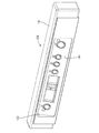
(6)関連技術6は、操作パネル130並びにその取付構造に関する。図1において、冷却庫本体10の上面にはテーブルを兼ねた天板125が被着され、同天板125の正面板の右端寄りの位置に窓孔126が開口されており、操作パネル130は、窓孔126に臨むようにして、本体10の前面開口部12の上縁部に取り付けられている。以下、図21ないし図23に基づいて説明する。
(6) Related technology 6 relates to
操作パネル130は、横長で後面開口の箱形をなす本体部131を備え、本体部131の正面には、上側に向かうほど深くなった斜めの凹部132が形成され、同凹部132の奥面が装着部133となって適宜に開口134が形成されている。一方、各種スイッチや電気部品を搭載した操作基板135を備え、同操作基板135は、上記した斜めの装着部133の裏面の両端部に突設された取付柱136を貫通して、各種スイッチ等を開口134に臨ませつつ装着部133の裏面に当てられ、しかるのち、断面略コ字形をなす押え板137が両取付柱136に当てられてねじ138で止められ、それに伴い、押え板137の上下両縁が操作基板135の上下両縁を押し付けて固定する。最後に、前面開口の箱形をなす裏カバー139が本体部131の後面開口内に緊密に嵌合され、下面板同士がねじ140で止められて固定される。なお、装着部133の表面には開口134を覆うようにして操作ラベル141が張られている。
本構造によれば、特に断面略コ字形の押え板137を利用して、操作基板135を装着部133の裏面に固定するようにしたから、操作パネル130の組立作業性に優れる。
The
According to this structure, since the
次に、操作パネル130の取付構造を説明する。本体部131の底面には、背面側に延出してなる被取付板142が、上記のねじ140による共締めによって固定されている。同被取付板142の延出端側の所定位置には、ねじ144の挿通孔143が開口されている。
一方、本体10の前面開口部12の上縁部12Bの所定位置には、チャンネル形の取付部材145がねじ146で固定されている。この取付部材145の底板147には、上記したねじ144が螺合されるねじ孔148が形成されている。この取付部材145の前面板149には、操作パネル130の裏カバー139が当接されるが、この前面板149は、図22に示すように、鉛直方向に対して上端側が手前側(同図の左側)に角度α(1°程度)だけ傾いた傾斜姿勢を取るように形成されている。
Next, the mounting structure of the
On the other hand, a channel-shaped
操作パネル130を取り付けるには、図22の矢線に示すように、被取付板142を取付部材145の底板147の下面に沿わせながら取付部材145に向けて押し込み、裏カバー139が前面板149に当たったのち、図23に示すように、同前面板149が鉛直姿勢を取るまで押し込むと、挿通孔143とねじ孔148とが整合するから、挿通孔143に通したねじ144をねじ孔148にねじ込むことで固定する。これにより、操作パネル130が取付部材145に取り付けられるが、このとき前面板149の復元弾力により、操作パネル130に対して上端側が前傾する方向の付勢力が付与される。
In order to attach the
操作パネル130によって操作する場合は、図23の矢線に示すように、指を操作ラベル141の表面から操作基板135に向けて押し付けることで行われ、操作パネル130は上端側が後傾する方向の押圧力を受けるが、取付部材145から上記と逆方向の付勢力を受けているから、操作パネル130を押圧した場合にも操作パネル130がぐらつくことが規制される。
When operating with the
(7)関連技術7は、当該急速冷凍庫を輸送する場合に用いる輸送用脚体150に関する。図1等に示すように、機械室40の外底面の四隅には、六角頭部を有するねじ状の脚11が取り付けられるが、輸送時には別途備えられた輸送用脚体150が装着されるようになっている。以下、図25ないし図27によって説明する。
輸送用脚体150は合成樹脂製であって、図24,図25に示すように、環形の基台151の内周から、上端部が縮径された段付き状の筒形をなす下面開放の柱部152が立ち上がり形成され、同柱部152の上面板153に、脚11のねじ棒11Aが挿通される挿通孔154が開口されている。
(7) The related technique 7 relates to the
The
この輸送用脚体150は基本的には、図24に参照して示すように、機械室40を上下反転姿勢としておいて同機械室40の底板40Aにおけるねじ孔40Bの切られた四隅に当てられ、内部に上記の脚11を入れて上面板153の挿通孔154からねじ孔40Bにねじ込むことで固定するようになっている。ただしその場合は、上下逆向きとなった輸送用脚体150の狭い底の部分において、工具により脚11のねじ込み操作をしなければならないため、操作し辛い嫌いがある。
Basically, as shown in FIG. 24, the
そこでこの例では、連結用のブラケット160が備えられてている。このブラケット160は金属板製であって、図24及び図26に示すように、平面長方形をなし、その中心に脚11のねじ棒11Aの挿通孔161が形成されているとともに、長辺側の側縁に、脚11の六角頭部11Bの平行二面を挟持する山形をなす側板162が立てられている。また、対角の隅部に一対の位置決め孔163が形成されている。
一方、輸送用脚体150の上面板153の裏面には、ブラケット160を当てる座面155が形成され、同座面155からは、上記した位置決め孔163に挿入される一対の位置決め爪156が、対応した配置で立ち上がり形成されている。
Therefore, in this example, a connecting bracket 160 is provided. The bracket 160 is made of a metal plate, and as shown in FIGS. 24 and 26, has a flat rectangular shape with an
On the other hand, a
輸送用脚体150を装着するには、図26に示すように、輸送用脚体150を上下反転姿勢とし、まず位置決め孔163に位置決め爪156を挿入しつつブラケット160を座面155に当て、続いてブラケット160の挿通孔161から上面板153の挿通孔154に亘って脚11のねじ棒11Aを挿通し、六角頭部11Bを両側板162で挟みつつブラケット160に当てる。これにより、ブラケット160が輸送用脚体150の上面板153の裏面に回り止めされて当てられ、そのブラケット160に対して脚11が回り止めされて嵌められることで、輸送用脚体150と脚11とがブラケット160を介して一体回転可能に連結された形態となる。
In order to mount the
このように組み付けられた輸送用脚体150は、その上面板153から突出した脚11のねじ棒11Aを機械室40の底板40Aのねじ孔40Bに螺合したのち、同輸送用脚体150をねじ込み方向に回転させると、脚11のねじ棒11Aがねじ込まれることで、図24に示すように、輸送用脚体150が脚11によって装着された状態となる。輸送用脚体150自身を回すことで装着できるから、装着作業を能率良く行うことができる。
設置現場では、輸送用脚体150を逆方向に回して脚11ともども外し、脚11を単独で取り出したのち、同脚11を改めてねじ孔40Bにねじ込んで装着すればよい。
The
At the installation site, the
<他の実施形態>
本発明は上記記述及び図面によって説明した実施形態に限定されるものではなく、例えば次のような実施形態も本発明の技術的範囲に含まれる。
(1)ホースカバーの側板に設けられる開口は、切欠孔に限らず、周縁を有する窓孔であってもよい。
(2)同じくホースカバーの側板に設けられる開口は、長さ方向に複数に分断された形態で形成されていてもよい。
(3)ドレンホースについて結露しやすいのは排水孔に接続された端部側といえるから、ホースカバーは同端部側のみを挿通する形状であってもよい。
<Other embodiments>
The present invention is not limited to the embodiments described with reference to the above description and drawings. For example, the following embodiments are also included in the technical scope of the present invention.
(1) The opening provided in the side plate of the hose cover is not limited to the notch hole but may be a window hole having a peripheral edge.
(2) Similarly, the opening provided in the side plate of the hose cover may be formed in a form divided into a plurality in the length direction.
(3) Since the drain hose is likely to condense on the end side connected to the drain hole, the hose cover may have a shape through which only the end side is inserted.
(4)庫内の底面において排水孔を設ける位置は任意であり、また、ドレンホースを引き出す面も任意に設定できる。
(5)冷却ユニットの配設位置は、上記実施形態とは逆に、庫内における正面視で右側に配置されていてもよい。
(6)本発明は上記実施形態に例示した急速冷却庫に限らず、要は庫内が相応の低温に冷却される一方、庫内の底面の排水孔に接続されたドレンホースが機械室の天井部を通って庫外に導出されるようにした冷却庫全般に広く適用することができる。
(4) The position where the drainage hole is provided on the bottom surface in the cabinet is arbitrary, and the surface for drawing out the drain hose can also be set arbitrarily.
(5) The arrangement position of the cooling unit may be arranged on the right side as viewed from the front in the warehouse, contrary to the above embodiment.
(6) The present invention is not limited to the rapid cooling cabinet illustrated in the above embodiment. In short, the inside of the warehouse is cooled to an appropriate low temperature, while the drain hose connected to the drain hole on the bottom surface in the warehouse is a machine room. The present invention can be widely applied to all refrigerators that are led out of the cabinet through the ceiling.
10…冷却庫本体 12…前面開口部 13…断熱扉(開閉扉) 15…収納室 16…設置室 20…冷却ユニット 21…冷却器 22…冷却ファン 40…機械室 41…フロントパネル 42…吸気口 43…冷凍装置 44…凝縮器 44A…凝縮器ファン 48…排気口 50…配管スペース 50A…天井面 52…庫内底面 53…最深部 55…排水孔体(排水孔) 58…ドレンホース 60…ホースカバー 61…底板 62…側板 63…前板 64…開口 65A,65B…取付板
DESCRIPTION OF
Claims (4)
前記冷却庫本体の庫内底面には排水孔が開口されて、同排水孔に一端が接続されたドレンホースが前記機械室の天井面側を通って前記ドレンホースの他端側が前記機械室の外部に導出されている冷却庫において、
前記機械室の天井面には、前記機械室内の前記ドレンホースに生じた結露水を受けるために前記ドレンホースを下方から覆うような形のホースカバーが装着され、
前記ホースカバーは、前記ドレンホースの下方に配され前記ドレンホースの配管方向に沿って延びる底板と、前記底板と共に前記ドレンホースを収容する溝状をなすように前記底板の両側縁からそれぞれ立ち上がり、上縁が前記天井面に固定される一対の側板とを有し、
前記ホースカバーの両側板には、前記機械室内の前記冷凍装置から排出された排熱を含む流通空気が通ることを許容する開口が形成されていることを特徴とする冷却庫。 A machine room is provided on the lower surface of the cooler body in which the inside is a storage room for storing an object to be cooled, and a cooling unit having a cooler and a cooling fan is provided on one side of the storage room. A refrigeration apparatus including a compressor and an air-cooled condenser is installed in the machine room, and is circulated and connected by the cooler and a refrigerant pipe. By driving the refrigeration apparatus and the cooling fan, the cooler The generated cold air is circulated and supplied to the storage chamber,
Wherein the storage room bottom of the refrigerator body are the drain hole is opened, the other end of the drain hose drain hose having one end in the drainage hole is connected through a ceiling surface side of the machine room of the machine room In the refrigerator led out to the outside,
A hose cover shaped to cover the drain hose from below is attached to the ceiling surface of the machine room in order to receive the condensed water generated in the drain hose in the machine room ,
The hose cover is disposed below the drain hose and extends along the piping direction of the drain hose, and rises from both side edges of the bottom plate so as to form a groove shape that accommodates the drain hose together with the bottom plate, A pair of side plates, the upper edges of which are fixed to the ceiling surface ;
An opening that allows passage air including exhaust heat discharged from the refrigeration apparatus in the machine room to pass through is formed in both side plates of the hose cover .
前記機械室内には、間口方向における前記設置室が設けられた側と対応する側に、前記冷凍装置が前記空冷式の凝縮器と前記圧縮機とを前後に並べた形態で設置され、
かつ前記機械室の前面における前記冷凍装置の前方に対応する領域に外気の吸気口が、同機械室における前記冷凍装置の設置側とは反対側の側面に排熱の排気口が形成されているとともに、
前記収納室の底面における前記設置室とは反対側の端縁側でかつ手前側の隅部に最深部が形成されて、同最深部に前記排水孔が形成され、
前記排水孔に前記一端が接続された前記ドレンホースの前記他端側が、前記機械室における前記冷凍装置の設置側とは反対側のスペースの天井面側を通って後方に向けて配管され、
前記ドレンホースにおける前記機械室内での配管部分のほぼ全長が、前記ホースカバーによって下方から覆われており、
前記ホースカバーの前記開口が、前記機械室の左右方向で前記排気口と重なるように配されることを特徴とする請求項1記載の冷却庫。 The cooling body has a structure having a front opening and an opening / closing door attached to the front opening, the storage body having the storage chamber on one side in the frontage direction and the cooling unit on the other side. There is an installation room where
In the machine room, on the side corresponding to the side where the installation chamber in the frontage direction is provided, the refrigeration apparatus is installed in a form in which the air-cooled condenser and the compressor are arranged in front and back,
In addition, an outside air intake port is formed in a region corresponding to the front of the refrigeration apparatus in the front surface of the machine room, and an exhaust heat exhaust port is formed on a side surface of the machine room opposite to the installation side of the refrigeration apparatus. With
The deepest portion is formed at the corner on the near side opposite to the installation chamber on the bottom surface of the storage chamber, and the drainage hole is formed at the deepest portion,
The other end of the drain hose one end of which is connected to the drainage hole, the installation side of the refrigeration system in the machine room are plumbed rearward through the ceiling surface side of the opposite side space,
Substantially the entire length of the pipe section in the machine room in the drain hose is covered from thus lower the hose cover,
The refrigerator according to claim 1 , wherein the opening of the hose cover is disposed so as to overlap the exhaust port in a left-right direction of the machine room .
Priority Applications (1)
| Application Number | Priority Date | Filing Date | Title |
|---|---|---|---|
| JP2012033619A JP5952584B2 (en) | 2012-02-20 | 2012-02-20 | Refrigerator |
Applications Claiming Priority (1)
| Application Number | Priority Date | Filing Date | Title |
|---|---|---|---|
| JP2012033619A JP5952584B2 (en) | 2012-02-20 | 2012-02-20 | Refrigerator |
Publications (2)
| Publication Number | Publication Date |
|---|---|
| JP2013170720A JP2013170720A (en) | 2013-09-02 |
| JP5952584B2 true JP5952584B2 (en) | 2016-07-13 |
Family
ID=49264785
Family Applications (1)
| Application Number | Title | Priority Date | Filing Date |
|---|---|---|---|
| JP2012033619A Expired - Fee Related JP5952584B2 (en) | 2012-02-20 | 2012-02-20 | Refrigerator |
Country Status (1)
| Country | Link |
|---|---|
| JP (1) | JP5952584B2 (en) |
Families Citing this family (2)
| Publication number | Priority date | Publication date | Assignee | Title |
|---|---|---|---|---|
| JP2014219142A (en) * | 2013-05-08 | 2014-11-20 | ホシザキ電機株式会社 | Refrigerator |
| CN108212245B (en) * | 2017-12-26 | 2019-11-05 | 青岛市黄岛区中心医院 | A kind of clinical laboratory's sample storage reaction device |
Family Cites Families (8)
| Publication number | Priority date | Publication date | Assignee | Title |
|---|---|---|---|---|
| JPH01169787U (en) * | 1988-05-18 | 1989-11-30 | ||
| JPH06241642A (en) * | 1993-02-12 | 1994-09-02 | Fuji Electric Co Ltd | Filtering device of showcase of refrigerating machine incorporating type |
| JP3048890B2 (en) * | 1995-07-26 | 2000-06-05 | 三洋電機株式会社 | Cooling storage |
| JP3962483B2 (en) * | 1998-05-15 | 2007-08-22 | ホシザキ電機株式会社 | Drain trap |
| JP2002054870A (en) * | 2000-05-29 | 2002-02-20 | Hoshizaki Electric Co Ltd | Draining structure of storage |
| JP4410947B2 (en) * | 2001-01-10 | 2010-02-10 | ホシザキ電機株式会社 | Exhaust structure for refrigerators, etc. |
| JP2002277146A (en) * | 2001-03-16 | 2002-09-25 | Hoshizaki Electric Co Ltd | Cooling storage tank with drain pan |
| JP5441431B2 (en) * | 2009-02-18 | 2014-03-12 | ホシザキ電機株式会社 | Refrigerator |
-
2012
- 2012-02-20 JP JP2012033619A patent/JP5952584B2/en not_active Expired - Fee Related
Also Published As
| Publication number | Publication date |
|---|---|
| JP2013170720A (en) | 2013-09-02 |
Similar Documents
| Publication | Publication Date | Title |
|---|---|---|
| JP4598188B2 (en) | Cooling storage | |
| JP5952584B2 (en) | Refrigerator | |
| JP2007024348A (en) | Cooling storage | |
| JP4644580B2 (en) | Cooling storage | |
| JP4518997B2 (en) | Cooling storage | |
| JP4570351B2 (en) | Cooling storage | |
| JP5104339B2 (en) | refrigerator | |
| WO2008001619A1 (en) | Cooling storage | |
| JP5165410B2 (en) | Refrigerator | |
| JP5441431B2 (en) | Refrigerator | |
| JP4555142B2 (en) | Cooling storage | |
| JP5952585B2 (en) | Refrigerator | |
| JP2006275474A (en) | Cooling storage | |
| JP5940832B2 (en) | Refrigerator | |
| JP5228505B2 (en) | refrigerator | |
| JP2004011931A (en) | Cooling chamber | |
| JP2012225526A (en) | Cooling storage | |
| JP4827420B2 (en) | Cooling storage | |
| JP4335083B2 (en) | Refrigerator | |
| JP2010190491A (en) | Cooling chamber | |
| JPH09236373A (en) | High humidity, low temperature storeroom | |
| JP3983565B2 (en) | Refrigerator | |
| JP2005291522A (en) | Cooling storage chamber | |
| JP5875934B2 (en) | Cooling storage | |
| JP2006343070A (en) | Cooling storage |
Legal Events
| Date | Code | Title | Description |
|---|---|---|---|
| A621 | Written request for application examination |
Free format text: JAPANESE INTERMEDIATE CODE: A621 Effective date: 20150121 |
|
| A977 | Report on retrieval |
Free format text: JAPANESE INTERMEDIATE CODE: A971007 Effective date: 20151028 |
|
| A131 | Notification of reasons for refusal |
Free format text: JAPANESE INTERMEDIATE CODE: A131 Effective date: 20151105 |
|
| A521 | Request for written amendment filed |
Free format text: JAPANESE INTERMEDIATE CODE: A523 Effective date: 20151215 |
|
| TRDD | Decision of grant or rejection written | ||
| A01 | Written decision to grant a patent or to grant a registration (utility model) |
Free format text: JAPANESE INTERMEDIATE CODE: A01 Effective date: 20160602 |
|
| A61 | First payment of annual fees (during grant procedure) |
Free format text: JAPANESE INTERMEDIATE CODE: A61 Effective date: 20160610 |
|
| R150 | Certificate of patent or registration of utility model |
Ref document number: 5952584 Country of ref document: JP Free format text: JAPANESE INTERMEDIATE CODE: R150 |
|
| S533 | Written request for registration of change of name |
Free format text: JAPANESE INTERMEDIATE CODE: R313533 |
|
| R350 | Written notification of registration of transfer |
Free format text: JAPANESE INTERMEDIATE CODE: R350 |
|
| LAPS | Cancellation because of no payment of annual fees |