JP5950581B2 - Combustion chamber pressure sensor for detecting the pressure in the combustion chamber of an internal combustion engine - Google Patents
Combustion chamber pressure sensor for detecting the pressure in the combustion chamber of an internal combustion engine Download PDFInfo
- Publication number
- JP5950581B2 JP5950581B2 JP2012003965A JP2012003965A JP5950581B2 JP 5950581 B2 JP5950581 B2 JP 5950581B2 JP 2012003965 A JP2012003965 A JP 2012003965A JP 2012003965 A JP2012003965 A JP 2012003965A JP 5950581 B2 JP5950581 B2 JP 5950581B2
- Authority
- JP
- Japan
- Prior art keywords
- combustion chamber
- pressure sensor
- chamber pressure
- diaphragm
- housing
- Prior art date
- Legal status (The legal status is an assumption and is not a legal conclusion. Google has not performed a legal analysis and makes no representation as to the accuracy of the status listed.)
- Expired - Fee Related
Links
Images

Classifications
-
- G—PHYSICS
- G01—MEASURING; TESTING
- G01L—MEASURING FORCE, STRESS, TORQUE, WORK, MECHANICAL POWER, MECHANICAL EFFICIENCY, OR FLUID PRESSURE
- G01L19/00—Details of, or accessories for, apparatus for measuring steady or quasi-steady pressure of a fluent medium insofar as such details or accessories are not special to particular types of pressure gauges
- G01L19/06—Means for preventing overload or deleterious influence of the measured medium on the measuring device or vice versa
- G01L19/0681—Protection against excessive heat
Landscapes
- Physics & Mathematics (AREA)
- General Physics & Mathematics (AREA)
- Measuring Fluid Pressure (AREA)
Description
従来技術によれば、内燃機関の燃焼室圧力を検出するための多くの圧力センサが公知である。これらの圧力センサは、ガソリンエンジンにも、ディーゼルエンジンにも使用することができる。このような形式の装置は、最近のエンジン制御装置の主要な構成部分を形成している。何故ならば、燃焼室圧力は、特に燃料消費及び排気ガスを減少させるために、非常に精確に検出されなければならないからである。 According to the prior art, many pressure sensors are known for detecting the combustion chamber pressure of an internal combustion engine. These pressure sensors can be used for gasoline engines as well as diesel engines. This type of device forms a major component of modern engine control systems. This is because the combustion chamber pressure must be detected very accurately, especially to reduce fuel consumption and exhaust gases.
本特許出願人と同一出願人による例えばドイツ連邦共和国特許出願第102009026436.1号明細書によれば、内燃機関の燃焼室圧力を検出するための様々な装置が公知である。このような公知の燃焼室圧力センサにおいては、センサハウジングが燃焼室側に少なくとも1つの閉鎖された開口を有しており、該開口は、少なくとも1つのダイヤフラムによって閉鎖されている。センサハウジング内に、少なくとも1つの機械電気式の変換エレメントが支持されており、少なくとも1つの、センサハウジングとは別個に構成された、ダイヤフラムの変形を機械電気式の変換エレメントに伝達するための伝達エレメントが設けられている。 Various devices for detecting the combustion chamber pressure of an internal combustion engine are known, for example, from German Patent Application No. 102009026436.1 by the same applicant as the present applicant. In such a known combustion chamber pressure sensor, the sensor housing has at least one closed opening on the combustion chamber side, which opening is closed by at least one diaphragm. At least one mechanoelectric conversion element is supported in the sensor housing and is configured to transmit at least one diaphragm deformation to the electromechanical conversion element, which is configured separately from the sensor housing. An element is provided.
燃焼室圧力センサのセンサハウジングを燃焼室周辺に対してシールするために、例えば前記特許文献DE102009026436.1号明細書に記載されているように、一般的な形式でフレキシブルなダイヤフラム、例えば金属ダイヤフラムが使用される。この金属ダイヤフラムは、小さい剛性に基づいて、いわゆる力経路(Kraftpfad)又は力伝達経路(Kraftuebertragungspfad)の一部を形成しており、この力伝達経路(複数存在する場合は、これらの伝達経路)を介して、燃焼室圧力によって生ぜしめられる力が本来のセンサエレメント、例えば機械電気式の変換エレメントに伝達される。燃焼過程中に、火炎フロント(火炎の先端)がダイヤフラム表面に少なくとも部分的に達すると、ダイヤフラム内に、燃焼室に向いた前方側と、燃焼室とは反対側の後ろ側との間で次第に変化する温度勾配を有するオーバーヒートが発生する。それによって、火炎フロントと同期する温度分布が形成される。しかしながらこのような温度分布が存在すると、ダイヤフラムは変形され、この変形が反作用力として力伝達経路に影響を与え、ひいては誤信号として、得ようとする圧力信号にオーバーラップされる。燃焼サイクルの時定数と共に発生する誤信号は、熱衝撃又は一時的ドリフトとも称呼される。このような作用を避けるか又は減少させるために、間接的な手段が用いられる。例えば火炎フロントが遮られる。しかしながら、このような間接的な手段は、ダイヤフラムの圧力レベルに反作用として作用する危険性を有している。これは同様に誤信号を生ぜしめる。 In order to seal the sensor housing of the combustion chamber pressure sensor with respect to the periphery of the combustion chamber, a flexible diaphragm, for example a metal diaphragm, is used in a general form, as described in, for example, the above-mentioned patent document DE102009026436.1. used. This metal diaphragm forms a part of the so-called force path (Kraftpfad) or force transmission path (Kraftuebertragungspfad) based on the small rigidity, and this force transmission path (there is a transmission path when there are multiple) Through this, the force generated by the combustion chamber pressure is transmitted to the original sensor element, for example, the electromechanical conversion element. During the combustion process, when the flame front (flame tip) reaches at least part of the diaphragm surface, it gradually enters the diaphragm between the front side facing the combustion chamber and the rear side opposite the combustion chamber. Overheating with a changing temperature gradient occurs. Thereby, a temperature distribution synchronized with the flame front is formed. However, when such a temperature distribution exists, the diaphragm is deformed, the deformation affects the force transmission path as a reaction force, and as a false signal, is overlapped with the pressure signal to be obtained. A false signal that occurs with the time constant of the combustion cycle is also referred to as thermal shock or transient drift. Indirect means are used to avoid or reduce such effects. For example, the flame front is blocked. However, such indirect means have the risk of acting as a reaction to the pressure level of the diaphragm. This also produces a false signal.
従って、以上のような作用が少なくとも十分に避けられるような燃焼室圧力センサが望まれている。特に、このような作用は、測定しようとする本来の圧力変化に与える影響ができるだけ小さく、前記熱衝撃作用を有利にはダイヤフラムの幾何学的な形状によって少なくとも十分に減少させる、直接的な手段に基づいて避けるようにするべきである。 Therefore, a combustion chamber pressure sensor that can avoid the above-described action at least sufficiently is desired. In particular, such an action is a direct means of having as little influence as possible on the original pressure change to be measured, and advantageously reducing the thermal shock action at least sufficiently by the diaphragm geometry. Should be avoided on the basis.
本発明の課題は、前記のような作用を十分に避けることができるような、内燃機関の燃焼室内の圧力を検出するための燃焼室圧力センサを提供することである。本発明は、ダイヤフラムに前記課題を解決するための最適な形状を付与することによって、及び有利にはダイヤフラムの単数又は複数の固定部を最適に位置決めすることによって、ダイヤフラム内の温度勾配の力作用が、信号に影響を与える軸方向の最小化された成分を有する、という認識に基づいている。温度勾配の力の反作用の、場合によっては避けることのできない半径方向成分は、大抵は不都合なものではない。何故ならば、このような半径方向成分は、大抵は、力経路方向に作用しないからである。 The subject of this invention is providing the combustion chamber pressure sensor for detecting the pressure in the combustion chamber of an internal combustion engine which can fully avoid the above effects. The present invention provides for the force action of the temperature gradient in the diaphragm by imparting the diaphragm with an optimal shape to solve the above problems, and preferably by optimally positioning the fixed part or parts of the diaphragm. Is based on the recognition that it has an axially minimized component that affects the signal. The radial component of the temperature gradient force reaction that is inevitable in some cases is usually not inconvenient. This is because such a radial component usually does not act in the direction of the force path.
本発明の燃焼室圧力センサは、ハウジングと、該ハウジングによって少なくとも部分的に包囲された内室とを有している。例えばこのハウジングは、内燃機関のシリンダヘッド内に設けるために構成されていてよい。例えばこのハウジングは、完全に又は部分的に金属材料より製造されているが、原則的に別の材料、例えばセラミック材料及び/又はプラスチック材料等を選択的に又は追加的に使用してもよい。この場合、ハウジングとは、一般的に、燃焼室圧力センサに少なくとも十分な外側形状を付与し、燃焼室圧力センサの内部を、機械的な負荷に対して及び有利には化学的な負荷に対しても保護することができる部材のことである。ハウジングは、例えば円柱形の形状を有しており、この場合、有利な形式で、燃焼室に向いた側の、ハウジングの端面に、斜めにカットした縁部及び/又は単数或いは複数のその他の形式のシール面が設けられており、これらの縁部及び/又はシール面によって、ハウジングをシリンダヘッド内に設ける際にシール作用が得られる。単数又は複数の内室は、少なくとも部分的にハウジングによって包囲されているので、内室は、少なくとも十分にハウジングによって規定される。ハウジング内及び有利には内室内に、少なくとも1つの機械電気式の、圧力を検出するための変換エレメントが支持されている。この場合、基本的に、機械的な信号を電気信号に変化するように、例えば圧力及び/又は力を電圧及び/又は電流に変換するように調整された任意のエレメントであってよい。以下では、機械電気式の変換エレメントが少なくとも1つの圧電エレメント、例えば少なくとも1つの圧電セラミックを有する構成について説明されているが、このような形式の機械電気式の変換エレメントのその他の可能な構成を制限するものではない。 The combustion chamber pressure sensor of the present invention has a housing and an inner chamber at least partially surrounded by the housing. For example, the housing may be configured for installation in a cylinder head of an internal combustion engine. For example, the housing is made entirely or partly from a metal material, but in principle other materials may be used selectively or additionally, for example ceramic materials and / or plastic materials. In this case, the housing generally gives the combustion chamber pressure sensor at least a sufficient outer shape so that the interior of the combustion chamber pressure sensor is mechanically and preferably chemically sensitive. It is a member that can be protected. The housing has, for example, a cylindrical shape, in which case, in an advantageous manner, at the end face of the housing on the side facing the combustion chamber, an obliquely cut edge and / or one or more other A type of sealing surface is provided, and these edges and / or sealing surfaces provide a sealing action when the housing is provided in the cylinder head. Since the inner chamber or chambers are at least partially surrounded by the housing, the inner chamber is at least fully defined by the housing. Supported in the housing and preferably in the inner chamber is at least one electromechanical conversion element for detecting pressure. In this case, it can basically be any element adjusted to convert a mechanical signal into an electrical signal, for example to convert pressure and / or force into voltage and / or current. In the following, a configuration is described in which the electromechanical conversion element comprises at least one piezoelectric element, for example at least one piezoelectric ceramic, but other possible configurations of this type of electromechanical conversion element are possible. It is not limited.
ハウジングは少なくとも1つのハウジング開口を有している。このハウジング開口は、例えば燃焼室に向いた、ハウジングの端面において、特に、燃焼室に向いていてよい。例えば前述のように、ハウジングは、ほぼ円柱形の形を有しており、この場合、縁部に円柱形の形からのずれが設けられており、ハウジング開口は、例えば燃焼室に向いた、シリンダの端面に配置されていてよい。ハウジング開口は、基本的に、燃焼室圧力を機械電気式の変換エレメントに伝達できるように、又は圧力をこのような形式で伝達できるように、調整されている。ハウジング開口は、基本的に任意の形状、例えば多角形形状又は円形の形状、有利には環状の形状を有していてよい。 The housing has at least one housing opening. This housing opening may, for example, face the combustion chamber, in particular at the end face of the housing, facing the combustion chamber. For example, as described above, the housing has a substantially cylindrical shape, in which case the edge is provided with a deviation from the cylindrical shape, the housing opening being directed, for example, to the combustion chamber, It may be arranged on the end face of the cylinder. The housing opening is basically adjusted so that the combustion chamber pressure can be transmitted to the electromechanical conversion element or the pressure can be transmitted in this manner. The housing opening can have essentially any shape, for example a polygonal or circular shape, preferably an annular shape.
ハウジング開口は、少なくとも1つのダイヤフラムによってシールされる。このシールは有利には完全に実施されるので、燃焼室ガスがハウジング開口を通って内室内に侵入することはない。このために、ダイヤフラムは単独で設けられているか、又は後述されているように、例えば単数又は複数のその他のエレメント例えば圧力伝達エレメントと協働するようになっていてもよい。この圧力伝達エレメントは、有利な形式でハウジング開口内に設けられているか、又はこのハウジング開口を貫通している。例えばダイヤフラム及び圧力伝達エレメントは一緒にハウジング開口をシールするようになっているので、燃焼室ガスが内室内に侵入することはない。 The housing opening is sealed by at least one diaphragm. This sealing is advantageously performed completely so that combustion chamber gases do not enter the inner chamber through the housing opening. For this purpose, the diaphragm may be provided alone or may cooperate with, for example, one or more other elements, such as a pressure transmission element, as described below. The pressure transmission element is provided in an advantageous manner in the housing opening or passes through the housing opening. For example, the diaphragm and the pressure transmission element are designed to seal the housing opening together so that combustion chamber gases do not enter the inner chamber.
ダイヤフラムとは、一般的に変形可能又は可動な部材のことであり、この部材は例えば、センサハウジングの軸線に対して垂直に延在しており、この場合、ダイヤフラムの側方の伸張例えばセンサハウジングの軸線に対して垂直な方向の伸張は、ダイヤフラムの厚さ例えばセンサハウジングの軸線に対して平行な方向の厚さを著しく超過しており、例えば少なくとも係数10だけ、特に少なくとも係数100だけ超過している。例えばダイヤフラムは、フレキシブルなエレメント、例えばシート状のエレメント又はフレキシブルな薄い円板状のエレメントであってよい。ダイヤフラムは、例えば金属製のダイヤフラムとして構成されていて、例えば少なくとも1つの金属シートを有していてよい。複数のシートの複合体、例えば複数の金属製の材料の複合体及び/又は、少なくとも1つの金属製のシート材料と少なくとも1つの非金属性のシート材料との複合体(この場合、非金属性のシート材料によって金属製のシート材料が結合されているかかつ/またはコーティングされている)も可能である。ダイヤフラムは、例えばハウジングと一体的に構成されていてよいが、少なくとも1つのハウジング開口の領域においてハウジングと、例えば摩擦結合(kraftschluessig;摩擦による束縛)式に及び/又は形状結合(formschluessig;形状による束縛)式に及び/又は素材結合(stoffschluessig;材料同士の結合)式に、例えば以下に詳しく説明されているように単数又は複数の固定部において結合されていてもよい。 A diaphragm is a generally deformable or movable member that extends, for example, perpendicular to the axis of the sensor housing, in which case the lateral extension of the diaphragm, for example the sensor housing The extension in the direction perpendicular to the axis of the filter significantly exceeds the thickness of the diaphragm, for example in the direction parallel to the axis of the sensor housing, for example by at least a factor 10 and in particular at least a factor 100. ing. For example, the diaphragm may be a flexible element, such as a sheet-like element or a flexible thin disk-like element. The diaphragm is configured as a metal diaphragm, for example, and may include, for example, at least one metal sheet. A composite of a plurality of sheets, for example a composite of a plurality of metallic materials and / or a composite of at least one metallic sheet material and at least one non-metallic sheet material (in this case non-metallic) It is also possible that the metal sheet material is bonded and / or coated by the other sheet material. The diaphragm may for example be constructed in one piece with the housing, but in the region of the at least one housing opening, for example in a friction-coupled manner and / or in a form-coupled shape ) And / or a material bond (stoffschluessig; material-to-material) formula, for example, as described in detail below, may be joined at one or more fixed portions.
本発明の枠内で、力の反作用の軸方向成分が温度勾配によって減少されるか又は少なくとも十分に避けられる、ダイヤフラムの最適な形状付与は、特にダイヤフラムが内室に向かって湾曲する少なくとも1つの凸状の湾曲部を有していることによって得られる。この場合、凸状の湾曲部とは、ダイヤフラムが、ダイヤフラムの延在方向に対して垂直な断面例えば燃焼室圧力センサの軸線に対して平行な断面で見て凸状の形状を有していて、凸状の側、つまり凸状の形状の閉じた側が内室に向いている形状のことである。例えばダイヤフラムは、燃焼室圧力センサの軸線に対して平行な断面で見て、少なくとも1つの局所的な最大延在箇所又は有利には広範囲な最大延在箇所を有しており、ダイヤフラムの閉じた側は内室に向いていて、開放した側は燃焼室に向いている。これによってダイヤフラムは、内室に向かって湾曲していて、有利には湾曲凸部が内室内に突入している。 Within the framework of the present invention, the optimal shaping of the diaphragm, in which the axial component of the force reaction is reduced or at least sufficiently avoided by the temperature gradient, is at least one in which the diaphragm curves towards the inner chamber. It is obtained by having a convex curved portion. In this case, the convex curved portion means that the diaphragm has a convex shape when viewed in a cross section perpendicular to the extending direction of the diaphragm, for example, a cross section parallel to the axis of the combustion chamber pressure sensor. The convex side, that is, the closed side of the convex shape is the shape facing the inner chamber. For example, the diaphragm has at least one local maximum extension, or preferably a wide range of maximum extensions, as viewed in a cross section parallel to the axis of the combustion chamber pressure sensor, and the diaphragm is closed. The side faces the inner chamber and the open side faces the combustion chamber. As a result, the diaphragm is curved toward the inner chamber, and advantageously, the curved convex portion enters the inner chamber.
燃焼室圧力センサは、少なくとも1つの圧力伝達エレメントを有している。この圧力伝達エレメントは、燃焼室圧力を少なくとも部分的に機械電気式の変換エレメントに伝達するように調整されている。従って、圧力伝達エレメントは、有利な形式で力伝達経路の構成部分であり、この場合、燃焼室圧力センサは単数又は複数の(有利には1つだけの)このような形式の力伝達経路を有していてよい。圧力伝達エレメントは、有利な形式で少なくとも1つの機械的に硬い材料を有していてよい。この硬い材料を介して燃焼室圧力は、機械電気式の変換エレメント(例えば円柱形及び/又は円筒形及び/又はロッド状のエレメント)に伝達される。特に圧力伝達エレメントは、少なくとも1つのロッドを有している。圧力伝達エレメントは、少なくとも部分的に内室内に配置されているか、又は完全に内室内に収容されていてもよい。圧力伝達エレメントは、例えばもっぱら内室内に延在しており、例えば機械電気式の変換エレメントからダイヤフラムに延在する。特に有利には、以下に詳しく記載されているように、圧力伝達エレメントはダイヤフラムを貫通して、例えば燃焼室に達しており、従って圧力伝達エレメントはハウジング開口内に突入しているか、又はハウジング開口を越えて延在している。従って圧力伝達エレメントは、直接的に又は間接的に(有利には直接的に)燃焼室圧力によって負荷可能である。これによって例えば圧力伝達経路は、燃焼室圧力が圧力伝達エレメント例えばロッドの端面(例えばこの端面が燃焼室ガスに直接接触していることによって)に直接作用するように構成されている。この燃焼室圧力は、有利な形式で圧力伝達エレメント及びダイヤフラムを介して、機械電気式の変換エレメント例えば圧電エレメントの端面に伝達される。しかしながらその他の構成も原則的に可能である。例えば単数又は複数の中間エレメントを圧力伝達エレメントと機械電気式の変換エレメントとの間に介在させることも可能である。 The combustion chamber pressure sensor has at least one pressure transmission element. The pressure transmission element is adjusted to transmit the combustion chamber pressure to the electromechanical conversion element at least partially. Thus, the pressure transmission element is advantageously a component of the force transmission path, in which case the combustion chamber pressure sensor has one or more (preferably only one) such type of force transmission path. You may have. The pressure transmission element may have at least one mechanically hard material in an advantageous manner. Through this hard material, the combustion chamber pressure is transmitted to an electromechanical conversion element (for example, a cylindrical and / or cylindrical and / or rod-shaped element). In particular, the pressure transmission element has at least one rod. The pressure transmission element may be at least partially disposed within the inner chamber or may be fully contained within the inner chamber. The pressure transmission element extends, for example, exclusively into the inner chamber, for example from a mechano-electric conversion element to the diaphragm. Particularly advantageously, as will be described in detail below, the pressure transmission element penetrates the diaphragm and reaches, for example, the combustion chamber, so that the pressure transmission element penetrates into the housing opening or the housing opening. Extends beyond. The pressure transmission element can therefore be loaded directly or indirectly (preferably directly) by the combustion chamber pressure. Thus, for example, the pressure transmission path is configured so that the combustion chamber pressure acts directly on the end face of the pressure transmission element, eg, the rod (eg, by direct contact of the end face with the combustion chamber gas). This combustion chamber pressure is transmitted in an advantageous manner via the pressure transmission element and the diaphragm to the end face of the electromechanical conversion element, for example a piezoelectric element. However, other configurations are possible in principle. For example, one or more intermediate elements can be interposed between the pressure transmission element and the electromechanical conversion element.
燃焼室圧力センサは、少なくとも1つの(有利には1つだけの)圧力伝達エレメント、例えばロッド、有利にはダイヤフラムを例えば軸方向に貫通するロッドを有しており、従ってダイヤフラムは、特に少なくとも1つの固定部をハウジングに有し、また圧力伝達エレメントに少なくとも1つの固定部を有している。この固定部は、原則として、単数又は複数の結合部、例えば単数又は複数の摩擦結合式の及び/又は形状結合式の及び/又は素材結合式の結合部、例えば溶接結合部及び/又は緊締結合部を有している。大抵の場合、1つの固定部は、1箇所内、1つのライン上又は1つの領域内に設けられていてよい。従って、可能な実施態様を制限することなしに、以下では、固定箇所、固定ライン又は固定領域とも称呼される。例えば、ハウジングへのダイヤフラムの固定部は、例えば円環状のラインに沿って環状に構成されていてよい。圧力伝達エレメントにおける固定部は、例えば面状に構成されているか、又はライン上に構成されていてよい。 The combustion chamber pressure sensor has at least one (preferably only one) pressure-transmitting element, for example a rod, preferably a rod, for example extending axially through the diaphragm, so that the diaphragm is in particular at least 1 One fixing part on the housing and at least one fixing part on the pressure transmission element. This fixing part is in principle one or more joints, for example one or more friction-bonded and / or shape-bonded and / or material-bonded joints, for example welded joints and / or tightened joints. Has a part. In most cases, one fixing portion may be provided in one place, on one line, or in one region. Therefore, without limiting the possible embodiments, in the following also referred to as fixing points, fixing lines or fixing areas. For example, the fixed portion of the diaphragm to the housing may be formed in an annular shape along an annular line, for example. The fixing part in the pressure transmission element may be configured in a planar shape, for example, or may be configured on a line.
従って、上述のように、特に有利には、圧力伝達エレメントはダイヤフラムの例えば中央部を貫通しており、例えばダイヤフラムの中央を貫通するロッドとして構成されている。この場合、有利には、圧力伝達エレメントにおける固定部は、外周面に少なくとも1つの固定ラインを有している。例えば圧力伝達エレメントは、円柱形のロッドとして構成されており、例えば円形又は多角形横断面を有するロッドを有している。この場合、固定部は、圧力伝達エレメントの外周面を包囲する閉じたラインを形成している。その他の構成も原則として可能である。圧力伝達エレメントは、燃焼室圧力センサの軸線に沿って延在していて、例えば軸方向のロッドとして構成されており、該ロッドは、少なくとも部分的にハウジング内に配置されていて、ダイヤフラムを貫通している。この場合、ダイヤフラムは、圧力伝達エレメントを特に環状に包囲している。 Thus, as mentioned above, the pressure transmission element is particularly advantageously configured as a rod that passes through, for example, the central part of the diaphragm, for example, through the center of the diaphragm. In this case, the fixing part in the pressure transmission element advantageously has at least one fixing line on the outer peripheral surface. For example, the pressure transmission element is configured as a cylindrical rod, for example with a rod having a circular or polygonal cross section. In this case, the fixed part forms a closed line surrounding the outer peripheral surface of the pressure transmission element. Other configurations are possible in principle. The pressure transmission element extends along the axis of the combustion chamber pressure sensor, for example configured as an axial rod, which is at least partly disposed in the housing and penetrates the diaphragm. doing. In this case, the diaphragm surrounds the pressure transmission element in a particularly annular manner.
ダイヤフラムが圧力伝達エレメントを環状に包囲するように構成されていれば、圧力伝達エレメントの軸線に対して平行な方向で見て、ダイヤフラムリングは、原則として任意の形状、有利には円環状の形状を有している。このような円環状の形状とは異なる形状、例えば外側形状が多角形に形成され、内側形状が同様に多角形に形成された形状も可能である。多角形の形状と円環状の形状との組み合わせも可能であり、またその他の円環状の形状も可能である。 If the diaphragm is configured to enclose the pressure transmission element in an annular shape, the diaphragm ring can in principle have any shape, preferably an annular shape, when viewed in a direction parallel to the axis of the pressure transmission element. have. A shape different from such an annular shape, for example, an outer shape formed into a polygon and an inner shape formed into a polygon is also possible. A combination of a polygonal shape and an annular shape is also possible, and other annular shapes are possible.
ダイヤフラムは、有利な形式で圧力伝達エレメントを環状に包囲している。ダイヤフラムは、特に圧力伝達エレメントの軸線に対して平行な断面、有利には軸線を含む断面で見て、これらのすべての断面においてU字形の形状を有している。U字形の形状とは、軸線を起点として、まず軸線に対して平行な少なくとも1つの方向成分を有する第1の方向に延在し、次いでこの第1の方向の少なくとも1つの最大延在箇所から、再び、前記第1の方向とは逆方向で、しかも軸線に対して平行な少なくとも1つの方向成分を有する第2の延在方向に延在する形状のことである。この場合、U字形の形状は、有利には連続的に構成されていて、丸味を付けられた形状又は折り曲げられた形状であってよい。従って、U字形とは、U字の形状、V字の形状又は長方形の形状を含むか、又は上記延在形状を含むその他の形状であってよい。U字形の形状の閉じた側は、前記湾曲を得るために、内室に向いていてよい。 The diaphragm encircles the pressure transmission element in an advantageous manner. The diaphragm has a U-shape in all these sections, especially when viewed in a section parallel to the axis of the pressure transmission element, preferably in a section including the axis. A U-shaped shape starts from an axis and first extends in a first direction having at least one directional component parallel to the axis, and then from at least one maximum extension in the first direction. Again, it is a shape extending in a second extending direction having at least one directional component that is opposite to the first direction and parallel to the axis. In this case, the U-shaped shape is advantageously constructed continuously and may be rounded or folded. Therefore, the U-shape may include a U-shape, a V-shape, a rectangular shape, or any other shape including the extended shape. The closed side of the U-shape may face the inner chamber to obtain the curvature.
圧力伝達エレメントが、燃焼室圧力センサの軸線に沿って延在していて、ダイヤフラムが圧力伝達エレメントを環状に包囲していれば、ダイヤフラムは特に、ハウジングにおいて外側の固定部、例えば円環状又は多角形の形状を有する外側の固定部を有している。また、ダイヤフラムは、圧力伝達エレメントにおいて内側の固定部を有しており、この固定部は前述のように、例えば圧力伝達エレメントの外側形状に適合した円環状又は多角形状の固定部として構成されている。内側の固定部は有利な形式で、dy>0だけ外側の固定部に対して内室に向かってずらして配置されている。この場合、dy>0.1mm、有利にはdy>0.3mmであって、例えばdy=0.4mm〜1.5mm、例えばdy=0.6mm〜0.8mm、有利にはdy=0.7mmである。内室へ向かって湾曲するダイヤフラムの前記湾曲部は、外側の固定部を起点として、内側の固定部を越えて内室へ向かって延在している。言い換えれば、外側の固定部と内側の固定部とは、圧力伝達エレメントの軸線に沿って互いにずらして配置されており、内側の固定部は外側の固定部に対して内室側へずらして配置されていて、外側の固定部と内側の固定部との間の湾曲部は、内側の固定部を越えて内室に突入している。このような構成は、例えば前記U字形の形状によって得られる。例えば湾曲部は、外側の固定部から、最大の軸方向寸法Yだけ内室に突入しており、この場合、比dy/Yは0.05〜0.8、有利には0.1〜0.5、特に有利には0.3〜0.4、特に0.35である。これは例えば、任意の横断面を有するU字形において、ハウジング側の、U字の長い方の脚部の長さに対する、U字のその他の脚部の長さの差が、前記比dy/Yの値を有していることによって、実現される。 If the pressure transmission element extends along the axis of the combustion chamber pressure sensor and the diaphragm surrounds the pressure transmission element in an annular shape, the diaphragm in particular has an outer fixed part in the housing, e.g. An outer fixing portion having a square shape is included. Further, the diaphragm has an inner fixing portion in the pressure transmission element, and the fixing portion is configured as an annular or polygonal fixing portion adapted to the outer shape of the pressure transmission element, for example, as described above. Yes. The inner fixing part is advantageously arranged and is displaced towards the inner chamber with respect to the outer fixing part by dy> 0. In this case, dy> 0.1 mm, preferably dy> 0.3 mm, for example dy = 0.4 mm to 1.5 mm, for example dy = 0.6 mm to 0.8 mm, preferably dy = 0. 7 mm. The curved portion of the diaphragm that curves toward the inner chamber extends from the outer fixed portion to the inner chamber beyond the inner fixed portion. In other words, the outer fixing portion and the inner fixing portion are arranged to be shifted from each other along the axis of the pressure transmission element, and the inner fixing portion is arranged to be shifted to the inner chamber side with respect to the outer fixing portion. The curved portion between the outer fixed portion and the inner fixed portion protrudes into the inner chamber beyond the inner fixed portion. Such a configuration is obtained, for example, by the U-shaped shape. For example, the curved portion enters the inner chamber from the outer fixed portion by the maximum axial dimension Y, in which case the ratio dy / Y is 0.05 to 0.8, preferably 0.1 to 0. .5, particularly preferably 0.3 to 0.4, in particular 0.35. For example, in a U-shape having an arbitrary cross section, the difference in the length of the other leg portion of the U-shape with respect to the length of the longer U-shape leg on the housing side is the ratio dy / Y. This is realized by having the value of
外側の固定部は直径を有しているが、外側の固定部が非円形に構成されている場合は、直径に等しい寸法が定められる。直径は例えば4mm〜8mm、有利には5mm〜7mm、特に6.3mmである。内側の固定部の直径は、2mm〜4mm、有利には2.5mm〜3.5mm、特に3.0mmである。 The outer fixing part has a diameter, but when the outer fixing part is configured to be non-circular, a dimension equal to the diameter is determined. The diameter is, for example, 4 mm to 8 mm, preferably 5 mm to 7 mm, in particular 6.3 mm. The diameter of the inner fixing part is 2 mm to 4 mm, preferably 2.5 mm to 3.5 mm, in particular 3.0 mm.
前述のように、圧力伝達エレメントは、特に内室から開口内に突入している。有利には、圧力伝達エレメントは、開口を貫通して内室から突き出して延在している。例えば、圧力伝達エレメントは端面を有しており、この端面は、燃焼室のガスに直接さらされているので、例えば燃焼室ガスの圧力が圧力伝達エレメントに直接伝達される。従って、圧力伝達エレメントによって、内室内において直接的又は間接的な圧力伝達が行われるか、又は機械電気式の変換エレメントに力が伝達される(これは本発明の枠内で区別されるべきではない)。 As described above, the pressure transmission element particularly enters the opening from the inner chamber. Advantageously, the pressure transmission element extends through the opening and protrudes from the inner chamber. For example, the pressure transmission element has an end face that is directly exposed to the combustion chamber gas, so that, for example, the pressure of the combustion chamber gas is directly transmitted to the pressure transmission element. Thus, the pressure transmission element provides direct or indirect pressure transmission in the interior chamber or transmits force to the electromechanical conversion element (this should not be distinguished within the framework of the invention). Absent).
以上述べた単独又は複数の有利な実施態様に基づく本願発明の燃焼室圧力センサは、後置の燃焼室圧力センサに対して多くの利点を有している。本発明によれば、特に、前記熱衝撃効果の作用が燃焼室圧力センサの信号に悪影響を及ぼすことが少なくとも十分に避けられるような、直接的な手段が提供されている。このような直接的な手段とは、これによってダイヤフラム及び/又は圧力伝達エレメントにおける圧力変動が影響を受けることがない手段のことである。特に、ダイヤフラムを前記のように構成したことによって、燃焼室圧力センサの信号に影響する軸方向の力成分を、少なくともほぼ最小にすることができる。これに対して、半径方向の力成分は、特に有利にはU字形状によって、無視できるか又は少なくとも許容できる。これによって、燃焼室圧力センサの信号品質は改善され、熱衝撃効果が信号に及ぼす影響は著しく減少される。 The combustion chamber pressure sensor of the present invention based on one or more advantageous embodiments described above has many advantages over the subsequent combustion chamber pressure sensor. According to the invention, in particular, a direct means is provided such that the action of the thermal shock effect is at least sufficiently avoided from adversely affecting the signal of the combustion chamber pressure sensor. Such direct means are means by which pressure fluctuations in the diaphragm and / or pressure transmission element are not affected. In particular, by configuring the diaphragm as described above, the axial force component that affects the signal of the combustion chamber pressure sensor can be at least substantially minimized. In contrast, the radial force component can be neglected or at least tolerated, particularly preferably by means of a U-shape. This improves the signal quality of the combustion chamber pressure sensor and significantly reduces the effect of thermal shock effects on the signal.
本発明の可能な実施態様のその他の詳細及び特徴は、図面に概略的に示した以下の実施例の説明に記載されている。 Other details and features of possible embodiments of the invention are described in the following description of examples, schematically illustrated in the drawings.
図1及び図2には、内燃機関の燃焼室112内の圧力pを検出するための本発明による燃焼室圧力センサの実施例が概略的に示されている。図面には、燃焼室圧力センサ110の軸線114に対して平行に断面した断面図が示されている。図1は、燃焼室圧力センサ110の全体を示しており、これに対して図2は、ダイヤフラム116の領域内の燃焼室圧力センサ110の部分図が示されている。このダイヤフラム116は、図1では概略的に示されている。
1 and 2 schematically show an embodiment of a combustion chamber pressure sensor according to the invention for detecting the pressure p in the
燃焼室圧力センサ110は、例えば図1に示されているように、内燃機関のシリンダヘッド118内に収容されている。燃焼室圧力センサ110はハウジング120を有しており、該ハウジング120は、図示の実施例では1例としてほぼ円柱形のハウジング120として構成されている。例えば、このハウジング120は円柱形のスリーブである。ハウジング120は、燃焼室112に向いた前方の端部に円錐形のシール面122を有している。このシール面122で以てハウジング120は、シリンダヘッド118内の孔126の対応する支承面124に向かって押し付けられる。
The combustion
ハウジング120は内室128を包囲している。後ろ側、つまり燃焼室圧力センサ110の、燃焼室112と反対側では、内室128は、単数又は複数の固定エレメント130によって仕切られているか、及び/又は少なくとも部分的に閉鎖されている。例えばこれらの固定エレメント130は、ハウジング120内でねじ結合されるか、かつ/または溶接される。ハウジングの外側で、燃焼室圧力センサ110の後ろ側の端部は、単数又は複数の外側の固定エレメント132によってシリンダヘッド118の孔126内で保持されている。
The
図示の実施例では、内室128内に、少なくとも1つの機械電気式の変換エレメント134、つまり原則として任意のセンサエレメントが収容されている。この変換エレメント134は、燃焼室112内の圧力pを直接的に又は間接的に検出するように調整されている。この変換エレメント134は例えば圧電素子であってよい。この変換エレメント134は、内室128内で単数又は複数の固定エレメント130によって支承されている。
In the illustrated embodiment, the
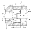
図示の実施例では、燃焼室圧力センサ110はさらに少なくとも1つの圧力伝達エレメント136を有している。この圧力伝達エレメント136は、例えば図示の実施例では、軸線114に沿って軸方向に支承されたロッド138として構成されており、該ロッド138は、圧力pを機械電気式の変換エレメント134に、直接的又は間接的に伝達するように調整されている。図1に示されているように、例えば圧力伝達エレメント136は、燃焼室112内に突入することによって燃焼室圧力に直接さらされる端面140を介して、燃焼室の圧力pによって軸方向で押圧される。押圧のために、ハウジング120は、その燃焼室112に向いた側の端部においてハウジング開口142例えば円形の開口を、ハウジング120の端面144に有している。図示の実施例では、圧力伝達エレメント136は、例えば前記ハウジング開口142を貫通して燃焼室112内まで突入している。しかしながらその他の実施態様も可能である。これによって、端面144は、図示の実施例では圧力伝達エレメント136を例えば同軸的に包囲する。
In the illustrated embodiment, the combustion
内室128をシールするために、燃焼室圧力センサ110は前記ダイヤフラム116を有しており、該ダイヤフラム116は図示の実施例では、例えば圧力伝達エレメント136を環状に包囲している。本発明によるダイヤフラム116の可能な構成は、図2に示されている。
In order to seal the
ダイヤフラム116は、その外周面において外側の固定部146に沿って、ハウジング120の内壁148に結合されている。この外側の固定部146は、例えば環状の溶接継ぎ目及び/又はその他の形式の固定手段を有している。ダイヤフラム116は、その内側の、圧力伝達エレメント136に向いた側が、該ダイヤフラム116の内側の固定部150に沿って、圧力伝達エレメント136の外側面152に結合されている。この内側の固定部は、例えば溶接継ぎ目及び/又は緊締及び/又はその他の形式の固定手段であってよい。外側の固定部146及び/又は内側の固定部150のために、原則としてすべての公知の結合形式、つまり形状結合(形状による束縛)式及び/又は摩擦結合(摩擦による束縛)式及び/又は素材結合(材料同士の結合)式の結合形式が考えられる。ハウジング120の内壁148及び/又は圧力伝達エレメント136の外側面152に設けた溝を介して、かつ例えば補助的な素材結合を用いて、簡単に係止することも考えられる。
The
図2に示されているように、図示の実施例では環状に構成されたダイヤフラム116が、内室128に向かって、つまり燃焼室112から離れる方向に延在する湾曲部154を備えたU字形の形状を有している。外側の固定部146を起点として、図2の横断面図で見て、ダイヤフラム116はまず、符号Yで示した軸方向寸法だけ、燃焼室112から離れる方向に内室128へ向かって延在する。この湾曲部154の最も外側に延在した領域においてダイヤフラム116は反転して燃焼室112に向かって、内側の固定部150まで延在する。全体的に、ダイヤフラム116は、U字形の閉じた側156が内室128に向いていて、これに対してU字形の開放した側158が燃焼室112に向いている。図2の有利な実施例に示されているように、内側の固定部150と外側の固定部146とは、軸方向で互いにずらされている。この場合、有利な形式で内側の固定部150は、軸方向でオフセットdyだけ内室128に向かって、つまり燃焼室112から離れる方向にずらされている。
As shown in FIG. 2, in the illustrated embodiment, the annularly configured
有限要素法(Finite-Elemente-Methode)によれば、図2に符号wで示されたダイヤフラム116の壁厚に亘って温度勾配が存在する場合、「ダイヤフラム固定点」又は「ダイヤフラム固定ライン」として設けられた2つの固定部146、150を、一般的にオフセットdyだけずらしておけば有利であることが確認されている。また例えば有限要素法に従ってシミュレーションすることによって、所定の形状のためには、ロッド138とハウジング120とのオフセットdyは所定の壁厚wにおいて、軸方向寸法Yに対して、熱衝撃効果が最小となるような所定の関係になければならないことが、明らかとなる。最適な関係dy/Yのためには、ロッド138の外径D1とハウジング120の内径D2とが、重要となる。しかしながら、精確な寸法とは無関係に、図2に示されているように、ダイヤフラム116の開放した側158は、前方つまり熱源(図示の実施例では燃焼室112)に向いている。寸法の具体的な例(本願発明はこの例に限定されるものではない)は、次の通りである。
D1=3.0mm
D2=6.3mm
w=0.3mm
Y=2.0mm
dy=0.7mm
これとは別の構成も、本発明の枠内で可能である。
According to the finite element method (Finite-Elemente-Methode), when there is a temperature gradient over the wall thickness of the
D1 = 3.0mm
D2 = 6.3mm
w = 0.3mm
Y = 2.0mm
dy = 0.7mm
Other configurations are possible within the scope of the present invention.
110 燃焼室圧力センサ、 112 燃焼室、 114 軸線、 116 ダイヤフラム、 118 シリンダヘッド、 120 ハウジング、 122 シール面、 124 支承面、 126 孔、 128 内室、 130 固定エレメント、 132 外側の固定エレメント、 134 変換エレメント、 136 圧力伝達エレメント、 138 ロッド、 146 外側の固定部、 148 内壁、 150 内側の固定部、 152 外側面、 154 湾曲部、 156 U字形の閉じた側、 158 U字形の開放した側 110 Combustion chamber pressure sensor, 112 Combustion chamber, 114 Axis, 116 Diaphragm, 118 Cylinder head, 120 Housing, 122 Seal surface, 124 Bearing surface, 126 holes, 128 Inner chamber, 130 Fixed element, 132 Outer fixed element, 134 Conversion Element, 136 pressure transmission element, 138 rod, 146 outer fixed part, 148 inner wall, 150 inner fixed part, 152 outer surface, 154 curved part, 156 U-shaped closed side, 158 U-shaped open side
Claims (17)
前記ダイヤフラム(116)が、前記内室(128)に向かって凸状に湾曲する少なくとも1つの湾曲部(154)を有しており、
前記ダイヤフラム(116)が、前記ハウジング(120)に外側の固定部(146)を有するとともに、前記圧力伝達エレメント(136)に内側の固定部(150)を有しており、内側の固定部(150)は外側の固定部(146)に対して内室(128)側へずらして配置されていて、外側の固定部(146)と内側の固定部(150)との間の湾曲部(154)は、内側の固定部(150)を越えて内室(128)に突入していることを特徴とする、内燃機関の燃焼室内の圧力を検出するための燃焼室圧力センサ(110)。 A combustion chamber pressure sensor (110) for detecting a pressure in a combustion chamber (112) of an internal combustion engine, the combustion chamber pressure sensor (110) being at least by a housing (120) and the housing (120) A partially enclosed inner chamber (128) within the housing (120), at least one mechano-electric conversion element (134) for detecting pressure, and a combustion chamber pressure. Housed is at least one pressure transmission element (136) for transmission at least partially to the electromechanical transducer element (134), the housing (120) having at least one housing opening (142). The housing opening (142) is sealed by at least one diaphragm (116) Stomach,
The diaphragm (116) has at least one curved portion (154) that curves convexly toward the inner chamber (128) ;
The diaphragm (116) has an outer fixing portion (146) in the housing (120) and an inner fixing portion (150) in the pressure transmission element (136). 150) is arranged so as to be shifted toward the inner chamber (128) with respect to the outer fixing portion (146), and the curved portion (154) between the outer fixing portion (146) and the inner fixing portion (150). ) Is a combustion chamber pressure sensor (110) for detecting the pressure in the combustion chamber of the internal combustion engine, which is inserted into the inner chamber (128) beyond the inner fixed portion (150 ).
Applications Claiming Priority (2)
| Application Number | Priority Date | Filing Date | Title |
|---|---|---|---|
| DE102011002596.0 | 2011-01-12 | ||
| DE201110002596 DE102011002596A1 (en) | 2011-01-12 | 2011-01-12 | Combustion chamber pressure sensor for detecting a pressure in a combustion chamber of an internal combustion engine |
Publications (3)
| Publication Number | Publication Date |
|---|---|
| JP2012145580A JP2012145580A (en) | 2012-08-02 |
| JP2012145580A5 JP2012145580A5 (en) | 2015-02-26 |
| JP5950581B2 true JP5950581B2 (en) | 2016-07-13 |
Family
ID=46454188
Family Applications (1)
| Application Number | Title | Priority Date | Filing Date |
|---|---|---|---|
| JP2012003965A Expired - Fee Related JP5950581B2 (en) | 2011-01-12 | 2012-01-12 | Combustion chamber pressure sensor for detecting the pressure in the combustion chamber of an internal combustion engine |
Country Status (4)
| Country | Link |
|---|---|
| US (1) | US8857250B2 (en) |
| JP (1) | JP5950581B2 (en) |
| CN (1) | CN102589798B (en) |
| DE (1) | DE102011002596A1 (en) |
Families Citing this family (10)
| Publication number | Priority date | Publication date | Assignee | Title |
|---|---|---|---|---|
| DE102009050911B4 (en) * | 2009-10-26 | 2014-06-12 | Borgwarner Beru Systems Gmbh | Cylinder pressure sensor |
| DE102011017667A1 (en) * | 2011-04-28 | 2012-10-31 | Robert Bosch Gmbh | Device for detecting a pressure, in particular a combustion chamber pressure of an internal combustion engine |
| DE102012209237A1 (en) * | 2012-05-31 | 2013-12-05 | Robert Bosch Gmbh | pressure measuring glow |
| WO2014034640A1 (en) * | 2012-08-29 | 2014-03-06 | シチズンファインテックミヨタ株式会社 | Combustion pressure sensor |
| US9103738B2 (en) | 2012-09-07 | 2015-08-11 | Dynisco Instruments Llc | Capacitive pressure sensor with intrinsic temperature compensation |
| DE102012219824A1 (en) | 2012-10-30 | 2014-04-30 | Robert Bosch Gmbh | Miniaturized combustion chamber pressure sensor with zugvorgespanntem sensor housing |
| JP6526467B2 (en) * | 2015-04-16 | 2019-06-05 | 株式会社ミクニ | Pressure sensor |
| DE102016225666A1 (en) | 2016-12-20 | 2018-06-21 | Piezocryst Advanced Sensorics Gmbh | Sensor housing for a force or pressure sensor, force or pressure sensor and method for producing a sensor housing |
| DE102016225652A1 (en) | 2016-12-20 | 2018-06-21 | Piezocryst Advanced Sensorics Gmbh | Method for producing a sensor housing for a force or pressure sensor and sensor housing, force or pressure sensor and use of an additive manufacturing device |
| CN108489654A (en) * | 2018-05-28 | 2018-09-04 | 西北工业大学 | A kind of spin friction weldering frictional interface part positive pressure force measuring device and measurement method |
Family Cites Families (21)
| Publication number | Priority date | Publication date | Assignee | Title |
|---|---|---|---|---|
| JPS5931045U (en) * | 1982-08-23 | 1984-02-27 | 株式会社日本自動車部品総合研究所 | pressure detector |
| US4586018A (en) * | 1983-09-19 | 1986-04-29 | Ford Motor Company | Combustion pressure sensor |
| JPH03211434A (en) * | 1990-01-17 | 1991-09-17 | Nissan Motor Co Ltd | Diaphragm type pressure sensor |
| DE4103705A1 (en) * | 1990-07-18 | 1992-01-23 | Bosch Gmbh Robert | PRESSURE SENSOR FOR DETECTING PRINTERS IN THE COMBUSTION CHAMBER OF COMBUSTION ENGINES |
| US6487898B1 (en) * | 1997-01-28 | 2002-12-03 | Eaton Corporation | Engine cylinder pressure sensor with thermal compensation element |
| DE10135568A1 (en) * | 2001-07-20 | 2003-02-06 | Endress & Hauser Gmbh & Co Kg | Differential or absolute pressure sensor has a hermetically sealed cap to protect measurement electronics from the external environment and prevent moisture ingress |
| US7369032B2 (en) * | 2003-01-09 | 2008-05-06 | Kulite Semiconductor Products, Inc. | Method of joining a pressure sensor header with an associated transducer element |
| DE10333438A1 (en) * | 2003-07-23 | 2005-02-17 | Robert Bosch Gmbh | Combustion chamber pressure sensor with metal diaphragm with piezoresistive metal thin film |
| JP4708711B2 (en) * | 2004-02-03 | 2011-06-22 | 株式会社デンソー | Pressure sensor |
| DE102004024341B3 (en) * | 2004-05-17 | 2005-12-22 | Beru Ag | pressure measuring glow |
| DE102004063749A1 (en) * | 2004-12-29 | 2006-07-13 | Robert Bosch Gmbh | Steel diaphragm for combustion chamber pressure sensors |
| DE102005035062A1 (en) * | 2005-07-27 | 2007-02-15 | Robert Bosch Gmbh | Device for measuring combustion chamber pressure of internal combustion engine has housing cover of heater plug provided for transmission of combustion chamber pressure to pressure measuring element |
| JP2008064529A (en) * | 2006-09-06 | 2008-03-21 | Denso Corp | Pressure sensitive sensor |
| DE102006043499A1 (en) * | 2006-09-12 | 2008-03-27 | Endress + Hauser Gmbh + Co. Kg | Method and device for diagnosing fluid losses in pressure transducers filled with pressure-transmitting fluids |
| JP4848904B2 (en) * | 2006-09-13 | 2011-12-28 | 株式会社デンソー | Pressure sensor |
| JP4835353B2 (en) * | 2006-09-27 | 2011-12-14 | 株式会社デンソー | Pressure sensor |
| DE102006057627A1 (en) * | 2006-12-05 | 2008-06-12 | Robert Bosch Gmbh | Pressure measuring device |
| DE102008009429A1 (en) * | 2007-03-15 | 2008-09-18 | Robert Bosch Gmbh | Seal for a glow plug |
| JP2011522263A (en) * | 2008-06-04 | 2011-07-28 | キストラー ホールディング アクチエンゲゼルシャフト | Pressure sensor for chamber measurement of internal combustion engines |
| DE102009026436A1 (en) | 2009-05-25 | 2010-12-09 | Robert Bosch Gmbh | Device for detecting a combustion chamber pressure of an internal combustion engine |
| DE102009022539A1 (en) * | 2009-05-25 | 2010-12-02 | Robert Bosch Gmbh | Device for detecting a combustion chamber pressure of an internal combustion engine |
-
2011
- 2011-01-12 DE DE201110002596 patent/DE102011002596A1/en not_active Withdrawn
- 2011-12-12 US US13/323,392 patent/US8857250B2/en not_active Expired - Fee Related
-
2012
- 2012-01-09 CN CN201210004137.5A patent/CN102589798B/en not_active Expired - Fee Related
- 2012-01-12 JP JP2012003965A patent/JP5950581B2/en not_active Expired - Fee Related
Also Published As
| Publication number | Publication date |
|---|---|
| CN102589798B (en) | 2017-03-01 |
| JP2012145580A (en) | 2012-08-02 |
| US20120174660A1 (en) | 2012-07-12 |
| US8857250B2 (en) | 2014-10-14 |
| DE102011002596A1 (en) | 2012-07-12 |
| CN102589798A (en) | 2012-07-18 |
Similar Documents
| Publication | Publication Date | Title |
|---|---|---|
| JP5950581B2 (en) | Combustion chamber pressure sensor for detecting the pressure in the combustion chamber of an internal combustion engine | |
| EP2679904B1 (en) | Glow plug with combustion pressure sensor | |
| US7730771B2 (en) | Device for detecting the combustion-chamber pressure in an internal combustion engine | |
| US7555932B2 (en) | Combustion pressure sensor | |
| US8939121B2 (en) | Glow plug fitted with combustion pressure detection sensor | |
| JP5191217B2 (en) | Piezoelectric pressure sensor | |
| JP2008002809A (en) | Combustion pressure sensor | |
| JP2005331236A (en) | Glow plug with pressure gauge | |
| JP6526467B2 (en) | Pressure sensor | |
| US9726376B2 (en) | Glow plug with combustion pressure sensor | |
| US20080223139A1 (en) | Combustion pressure sensor | |
| JP2008026326A (en) | Pressure measuring device | |
| JP2009144702A (en) | Combustion pressure sensor | |
| CN104246464B (en) | Membrane for combustion chamber pressure sensor | |
| US20150135811A1 (en) | Diaphragm for a pressure-measuring device | |
| US20050126297A1 (en) | Pressure sensor element having an integrated sealing surface | |
| JP7021029B2 (en) | Gas sensor | |
| JP2007085577A (en) | Glow plug with combustion pressure sensor | |
| JP2009236438A (en) | Glow plug | |
| JP2015135252A (en) | gas sensor | |
| JP2020183880A (en) | Pressure sensor | |
| JP2020106512A (en) | In-cylinder pressure sensor | |
| EP3247942B1 (en) | Glow plug including a load sensor and a welded flexible distal membrane having a transversal flexible collar | |
| JP2007085578A (en) | Glow plug with combustion pressure sensor | |
| JP6130265B2 (en) | Glow plug with pressure sensor |
Legal Events
| Date | Code | Title | Description |
|---|---|---|---|
| A521 | Written amendment |
Free format text: JAPANESE INTERMEDIATE CODE: A523 Effective date: 20150109 |
|
| A621 | Written request for application examination |
Free format text: JAPANESE INTERMEDIATE CODE: A621 Effective date: 20150109 |
|
| A977 | Report on retrieval |
Free format text: JAPANESE INTERMEDIATE CODE: A971007 Effective date: 20151105 |
|
| A131 | Notification of reasons for refusal |
Free format text: JAPANESE INTERMEDIATE CODE: A131 Effective date: 20151116 |
|
| A521 | Written amendment |
Free format text: JAPANESE INTERMEDIATE CODE: A523 Effective date: 20160210 |
|
| TRDD | Decision of grant or rejection written | ||
| A01 | Written decision to grant a patent or to grant a registration (utility model) |
Free format text: JAPANESE INTERMEDIATE CODE: A01 Effective date: 20160509 |
|
| A61 | First payment of annual fees (during grant procedure) |
Free format text: JAPANESE INTERMEDIATE CODE: A61 Effective date: 20160607 |
|
| R150 | Certificate of patent or registration of utility model |
Ref document number: 5950581 Country of ref document: JP Free format text: JAPANESE INTERMEDIATE CODE: R150 |
|
| LAPS | Cancellation because of no payment of annual fees |