JP5943583B2 - Reinforced structure of spent fuel rack - Google Patents
Reinforced structure of spent fuel rack Download PDFInfo
- Publication number
- JP5943583B2 JP5943583B2 JP2011247744A JP2011247744A JP5943583B2 JP 5943583 B2 JP5943583 B2 JP 5943583B2 JP 2011247744 A JP2011247744 A JP 2011247744A JP 2011247744 A JP2011247744 A JP 2011247744A JP 5943583 B2 JP5943583 B2 JP 5943583B2
- Authority
- JP
- Japan
- Prior art keywords
- spent fuel
- fuel rack
- rack
- damper device
- pool
- Prior art date
- Legal status (The legal status is an assumption and is not a legal conclusion. Google has not performed a legal analysis and makes no representation as to the accuracy of the status listed.)
- Active
Links
Images


Classifications
-
- Y—GENERAL TAGGING OF NEW TECHNOLOGICAL DEVELOPMENTS; GENERAL TAGGING OF CROSS-SECTIONAL TECHNOLOGIES SPANNING OVER SEVERAL SECTIONS OF THE IPC; TECHNICAL SUBJECTS COVERED BY FORMER USPC CROSS-REFERENCE ART COLLECTIONS [XRACs] AND DIGESTS
- Y02—TECHNOLOGIES OR APPLICATIONS FOR MITIGATION OR ADAPTATION AGAINST CLIMATE CHANGE
- Y02E—REDUCTION OF GREENHOUSE GAS [GHG] EMISSIONS, RELATED TO ENERGY GENERATION, TRANSMISSION OR DISTRIBUTION
- Y02E30/00—Energy generation of nuclear origin
- Y02E30/30—Nuclear fission reactors
Description
本発明は、原子炉から取り出された使用済燃料棒を一時的に貯蔵する使用済燃料ラックの補強構造に関するものである。 The present invention relates to a spent fuel rack reinforcing structure for temporarily storing spent fuel rods taken out from a nuclear reactor.
原子力発電プラントの一つとして、加圧水型原子炉があり、この加圧水型原子炉では、軽水を原子炉冷却材及び中性子減速材として使用し、一次系全体にわたって沸騰しない高温高圧水とし、この高温高圧水を蒸気発生器に送って熱交換により蒸気を発生させ、この蒸気をタービン発電機へ送って発電している。 One of the nuclear power plants is a pressurized water reactor. In this pressurized water reactor, light water is used as a reactor coolant and a neutron moderator, and high-temperature and high-pressure water that does not boil throughout the primary system is used. Water is sent to a steam generator to generate steam by heat exchange, and this steam is sent to a turbine generator to generate electricity.
このような原子力発電プラントでは、加圧水型原子炉から取り出された使用済燃料棒を一時的に貯蔵する使用済燃料プールが原子炉建屋に設けられており、この使用済燃料プールには、多数の使用済燃料棒を立てた状態で支持する使用済燃料ラックが設置されている。このような使用済燃料ラックとしては、例えば、下記特許文献1に記載されたものがある。この特許文献1に記載された燃料ラック上部支持構造は、燃料ラックの上部を支持する一体形スペーサを設け、この一体形スペーサを、燃料ラック間及び燃料ラックと燃料プール壁の間にその間隙を埋めるテーパ状のスペーサと、各スペーサを一体に結合するフレームとから構成し、一体形スペーサ全体の自重によって燃料ラックの上部に設置するものである。 In such a nuclear power plant, a spent fuel pool for temporarily storing spent fuel rods taken out from the pressurized water reactor is provided in the reactor building. A spent fuel rack that supports the spent fuel rods in an upright state is installed. As such a spent fuel rack, there exists a thing described in the following patent document 1, for example. The fuel rack upper support structure described in Patent Document 1 includes an integrated spacer that supports the upper portion of the fuel rack, and the integrated spacer is provided between the fuel racks and between the fuel rack and the fuel pool wall. The spacer is composed of a tapered spacer to be filled and a frame for integrally joining the spacers, and is installed on the upper part of the fuel rack by its own weight.
上述した従来の燃料ラック上部支持構造では、燃料ラック間及び燃料ラックと燃料プール壁の間に挿入するテーパ状のスペーサが必要となる。即ち、このテーパ状のスペーサを多数用いなければならず、構造が複雑となってしまう。また、燃料ラック間の隙間量や燃料ラックと燃料プール壁の間の隙間にばらつきがあった場合、テーパ状のスペーサは適正にその隙間に挿入されず、ラックの耐震性を十分に確保することが困難となる。 The conventional fuel rack upper support structure described above requires a tapered spacer inserted between the fuel racks and between the fuel rack and the fuel pool wall. That is, many taper spacers must be used, and the structure becomes complicated. Also, if there are variations in the gap between the fuel racks or the gap between the fuel rack and the fuel pool wall, the tapered spacers will not be properly inserted into the gap, and the rack will have sufficient earthquake resistance. It becomes difficult.
本発明は上述した課題を解決するものであり、構造の簡素化及び低コスト化を可能とする一方で、適正に使用済燃料ラックの耐震性を向上することが可能な使用済燃料ラックの補強構造を提供することを目的とする。 SUMMARY OF THE INVENTION The present invention solves the above-described problems, and can reinforce spent fuel racks that can appropriately improve the earthquake resistance of spent fuel racks while simplifying the structure and reducing costs. The purpose is to provide a structure.
上記の目的を達成するための本発明の使用済燃料ラックの補強構造は、使用済燃料を鉛直方向に沿って上方から挿入可能な複数のセルを有し、下部が使用済燃料プールの底部に固定された使用済燃料ラックにおいて、前記使用済燃料プールの壁面と前記使用済燃料ラックの側面との間にダンパ装置が設けられる、ことを特徴とするものである。 In order to achieve the above object, the spent fuel rack reinforcing structure of the present invention has a plurality of cells into which spent fuel can be inserted from above along the vertical direction, and the lower part is located at the bottom of the spent fuel pool. In the fixed spent fuel rack, a damper device is provided between a wall surface of the spent fuel pool and a side surface of the spent fuel rack.
従って、使用済燃料ラックは、水平揺れがダンパ装置により抑制されることで、使用済燃料ラックの耐震性を向上することができると共に、構造の簡素化及び低コスト化を可能とすることができる。 Therefore, in the spent fuel rack, the horizontal swing is suppressed by the damper device, so that the earthquake resistance of the spent fuel rack can be improved, and the structure can be simplified and the cost can be reduced. .
本発明の使用済燃料ラックの補強構造では、前記ダンパ装置は、前記使用済燃料プールの壁面と前記使用済燃料ラックの上部側面との間であって、前記使用済燃料ラックの四方に設けられることを特徴としている。 In the reinforcing structure for a spent fuel rack according to the present invention, the damper device is provided between a wall surface of the spent fuel pool and an upper side surface of the spent fuel rack, and is provided on four sides of the spent fuel rack. It is characterized by that.
従って、使用済燃料ラックは、下部が使用済燃料プールの底部に固定され、上部が四方をダンパ装置により支持されることで、使用済燃料ラックの水平揺れを適正に抑制し、耐震性を向上することができる。 Therefore, the spent fuel rack has its lower part fixed to the bottom of the spent fuel pool and its upper part supported by the damper device on all four sides, thereby suppressing the horizontal shaking of the spent fuel rack and improving the earthquake resistance. can do.
本発明の使用済燃料ラックの補強構造では、前記ダンパ装置は、内部に充填された流体の移動により機能することを特徴としている。 In the spent fuel rack reinforcing structure according to the present invention, the damper device functions by movement of a fluid filled therein.
従って、使用済燃料ラックは、水平揺れがダンパ装置の内部に充填された流体の移動により抑制されることで、使用済燃料ラックの耐震性を向上することができる。 Therefore, in the spent fuel rack, the horizontal vibration is suppressed by the movement of the fluid filled in the damper device, so that the earthquake resistance of the spent fuel rack can be improved.
本発明の使用済燃料ラックの補強構造では、前記ダンパ装置は、前記使用済燃料プールの冷却水に浸漬したピストン機構を有し、該ピストン機構は、シリンダ内に所定の隙間をもってピストンが移動自在に支持されて構成されることを特徴としている。 In the spent fuel rack reinforcing structure according to the present invention, the damper device has a piston mechanism immersed in the cooling water of the spent fuel pool, and the piston mechanism can move the piston with a predetermined gap in the cylinder. It is characterized by being supported by.
従って、使用済燃料ラックは、水平揺れが発生したとき、ピストンの移動時に冷却水がシリンダとピストンとの隙間を通過するオリフィス効果によりこの水平揺れが抑制されることとなり、使用済燃料プールの冷却水を用いることで、構造の簡素化及び低コスト化を可能とすることができる。 Therefore, in the spent fuel rack, when horizontal shaking occurs, the horizontal shaking is suppressed by the orifice effect in which the cooling water passes through the gap between the cylinder and the piston when the piston moves, and the spent fuel pool is cooled. By using water, the structure can be simplified and the cost can be reduced.
本発明の使用済燃料ラックの補強構造では、前記ダンパ装置は、内部に充填されたダイラタント流体の移動により機能することを特徴としている。 In the reinforcing structure for a spent fuel rack according to the present invention, the damper device functions by movement of a dilatant fluid filled therein.
従って、使用済燃料ラックの水平揺れを抑制する流体としてダイラタント流体を用いることで、効果的に使用済燃料ラックの耐震性を向上することができる。 Therefore, by using the dilatant fluid as the fluid that suppresses the horizontal shaking of the spent fuel rack, it is possible to effectively improve the earthquake resistance of the spent fuel rack.
本発明の使用済燃料ラックの補強構造では、前記ダンパ装置は、ピストン機構を有し、該ピストン機構は、シリンダ内に前記ダイラタント流体が充填されると共に、前記シリンダ内の前記ダイラタント流体内でピストンが移動自在に支持されて構成されることを特徴としている。 In the reinforcing structure for a spent fuel rack according to the present invention, the damper device has a piston mechanism, and the piston mechanism is filled with the dilatant fluid in a cylinder, and the piston in the dilatant fluid in the cylinder. Is characterized by being configured to be movably supported.
従って、使用済燃料ラックは、水平揺れが発生したとき、ピストンが移動するためにダイラタント流体の粘度が上昇し、ピストンの移動が制限されることによりこの水平揺れが抑制されることとなり、構造の簡素化及び低コスト化を可能とすることができる。 Therefore, in the spent fuel rack, when the horizontal shaking occurs, the piston moves, the viscosity of the dilatant fluid increases, and the movement of the piston is restricted, thereby suppressing the horizontal shaking. Simplification and cost reduction can be achieved.
本発明の使用済燃料ラックの補強構造では、前記ダンパ装置は、同極部が所定の間隔をもって対向配置された一対の磁石を有することを特徴としている。 In the structure for reinforcing a spent fuel rack according to the present invention, the damper device has a pair of magnets in which the same pole portions are arranged to face each other at a predetermined interval.
従って、使用済燃料ラックは、水平揺れが一対の磁石の反発力により抑制されることで、構造の簡素化を可能とすることができる。 Therefore, the spent fuel rack can be simplified in structure because the horizontal swing is suppressed by the repulsive force of the pair of magnets.
本発明の使用済燃料ラックの補強構造では、前記ダンパ装置は、震度が予め設定された所定震度を超えると、内圧が上昇する袋状部材を有することを特徴としている。 In the structure for reinforcing a spent fuel rack according to the present invention, the damper device has a bag-like member that increases the internal pressure when the seismic intensity exceeds a predetermined seismic intensity.
従って、使用済燃料ラックは、震度が所定震度を超えて水平揺れが発生すると、袋状部材の内圧が上昇することで、この水平揺れが抑制されることとなり、使用済燃料ラックの耐震性を向上することができる。 Therefore, when the seismic intensity exceeds the predetermined seismic intensity and the horizontal shaking occurs, the spent fuel rack increases the internal pressure of the bag-like member, which suppresses the horizontal shaking, and improves the seismic resistance of the spent fuel rack. Can be improved.
本発明の使用済燃料ラックの補強構造によれば、使用済燃料プールの壁面と使用済燃料ラックの側面との間にダンパ装置を設けるので、使用済燃料ラックの耐震性を向上することができると共に、構造の簡素化及び低コスト化を可能とすることができる。 According to the reinforcing structure of the spent fuel rack of the present invention, since the damper device is provided between the wall surface of the spent fuel pool and the side surface of the spent fuel rack, the earthquake resistance of the spent fuel rack can be improved. At the same time, the structure can be simplified and the cost can be reduced.
以下に添付図面を参照して、本発明に係る使用済燃料ラックの補強構造の好適な実施例を詳細に説明する。なお、この実施例により本発明が限定されるものではなく、また、実施例が複数ある場合には、各実施例を組み合わせて構成するものも含むものである。 Exemplary embodiments of a spent fuel rack reinforcing structure according to the present invention will be explained below in detail with reference to the accompanying drawings. In addition, this invention is not limited by this Example, Moreover, when there exists multiple Example, what comprises combining each Example is also included.
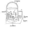
図1は、本発明の実施例1に係る使用済燃料ラックの補強構造を表す使用済燃料プールの平面図、図2は、実施例1の使用済燃料ラックの補強構造を表す使用済燃料プールの縦断面図、図3は、ダンパ装置の概略図、図4は、原子力発電プラントを表す概略構成図、図5は、原子炉格納容器を表す概略図である。 FIG. 1 is a plan view of a spent fuel pool representing a spent fuel rack reinforcing structure according to a first embodiment of the present invention, and FIG. 2 is a spent fuel pool representing a spent fuel rack reinforcing structure according to the first embodiment. FIG. 3 is a schematic diagram of a damper device, FIG. 4 is a schematic configuration diagram showing a nuclear power plant, and FIG. 5 is a schematic diagram showing a nuclear reactor containment vessel.
実施例1の原子力発電プラントに適用された原子炉は、軽水を原子炉冷却材及び中性子減速材として使用し、一次系全体にわたって沸騰しない高温高圧水とし、この高温高圧水を蒸気発生器に送って熱交換により蒸気を発生させ、この蒸気をタービン発電機へ送って発電する加圧水型原子炉(PWR:Pressurized Water Reactor)である。 The nuclear reactor applied to the nuclear power plant of Example 1 uses light water as a reactor coolant and a neutron moderator to produce high-temperature and high-pressure water that does not boil over the entire primary system, and sends this high-temperature and high-pressure water to a steam generator. This is a pressurized water reactor (PWR) that generates steam by heat exchange and sends the steam to a turbine generator to generate electricity.
即ち、この加圧水型原子炉を有する原子力発電プラントにおいて、図4に示すように、原子炉格納容器11内には、加圧水型原子炉12及び蒸気発生器13が格納されており、この加圧水型原子炉12と蒸気発生器13とは冷却水配管14,15を介して連結されており、冷却水配管14に加圧器16が設けられ、冷却水配管15に冷却水ポンプ17が設けられている。この場合、減速材及び一次冷却水として軽水を用い、炉心部における一次冷却水の沸騰を抑制するために、一次冷却系統は加圧器16により160気圧程度の高圧状態を維持するように制御している。従って、加圧水型原子炉12にて、燃料として低濃縮ウランまたはMOXにより一次冷却水として軽水が加熱され、高温の一次冷却水が加圧器16により所定の高圧に維持された状態で冷却水配管14を通して蒸気発生器13に送られる。この蒸気発生器13では、高圧高温の一次冷却水と二次冷却水との間で熱交換が行われ、冷やされた一次冷却水は冷却水配管15を通して加圧水型原子炉12に戻される。
That is, in the nuclear power plant having this pressurized water reactor, as shown in FIG. 4, the pressurized
蒸気発生器13は、原子炉格納容器11の外部に設けられたタービン18及び復水器19と冷却水配管20,21を介して連結されており、冷却水配管21に給水ポンプ22が設けられている。また、タービン18には発電機23が接続され、復水器19には冷却水(例えば、海水)を給排する取水管24及び排水管25が連結されている。従って、蒸気発生器13にて、高圧高温の一次冷却水と熱交換を行って生成された蒸気は、冷却水配管20を通してタービン18に送られ、この蒸気によりタービン18を駆動して発電機23により発電を行う。タービン18を駆動した蒸気は、復水器19で冷却された後、冷却水配管21を通して蒸気発生器13に戻される。
The
このように構成された原子力発電プラントの原子炉格納容器11は、図5に示すように、内部に上述した加圧水型原子炉12、蒸気発生器13、加圧器16などが収容されている。一方、原子炉格納容器11に隣接して燃料取扱建屋30が設置され、この燃料取扱建屋30内に使用済み燃料プール31が設けられており、この使用済み燃料プール31の内部に使用済み燃料ラック32が設置されている。この使用済み燃料ラック32は、加圧水型原子炉12で使用された使用済の燃料(燃料棒)を一時的に貯蔵するものであり、この使用済み燃料ラック32に貯蔵された使用済燃料は、使用済み燃料プール31に充填され、且つ、循環する冷却水により冷却可能となっている。
As shown in FIG. 5, the nuclear reactor power
使用済み燃料ラック32は、図1及び図2に示すように、底付の四角筒形状をなし、上方が開口しており、内部に複数の四角管が均等間隔で配置され、溶接により固定されることで、使用済燃料を鉛直方向に沿って上方から挿入可能な複数のセル32aが形成されている。このセル32aは、使用済み燃料ラック32内の下部に隣接するもの同士が連通している。
As shown in FIGS. 1 and 2, the spent
使用済み燃料プール31は、所定の大きさを有し、底部31aにベースフレーム33が固定されており、使用済燃料ラック32がこのベースフレーム33上に固定されている。この使用済燃料ラック32は、使用済み燃料プール31内の中央にて、ベースフレーム33上に互いに所定の隙間をもって6個配置されており、使用済み燃料プール31の壁面との間に所定の隙間をもって配置されている。そして、使用済み燃料プール31は、内部に使用済燃料ラック32の全体が浸漬されるように冷却水が充填されている。
The spent
実施例1の使用済燃料ラックの補強構造は、使用済燃料プール31の壁面31bと使用済燃料ラック32の側面32bとの間にダンパ装置41が設けられて構成されている。
The spent fuel rack reinforcing structure according to the first embodiment is configured by providing a
使用済燃料ラック32は、上述したように、使用済み燃料プール31のベースフレーム33上に互いに所定間隔をもって6個配置されている。ダンパ装置41は、使用済燃料プール31の壁面31bと使用済燃料ラック32の上部側面32bとの間であって、6個の使用済燃料ラック32の四方に設けられている。
As described above, six spent
そして、各ダンパ装置41は、内部に充填された流体(冷却水)の移動により機能するものである。即ち、このダンパ装置41は、使用済燃料プール31の冷却水に浸漬したピストン機構を有し、このピストン機構は、シリンダ内に所定隙間をもってピストンが移動自在に支持されて構成されている。
Each
ダンパ装置41において、シリンダ42は一方が開口して他方が閉塞した筒形状をなし、閉塞した端部が連結ロッド43により使用済燃料プール31の壁面31bに連結されている。ピストン44は、シリンダ42の内径より若干小さい外径であり、このシリンダ42の内部に所定隙間Sをもって移動自在に支持されており、一方の端面部が連結ロッド45により使用済燃料ラック32の側面32bに連結されている。この場合、シリンダ42とピストン44によりピストン機構が構成され、このピストン44の外周面とシリンダ42の内周面との所定隙間Sがオリフィスとして機能する。
In the
なお、本実施例では、使用済み燃料プール31内に固定された6個の使用済燃料ラック32の周囲に複数のダンパ装置41を設けており、隣接する使用済燃料ラック32同士を図示しない連結部材により連結するとよい。また、使用済燃料プール31の壁面31bと使用済燃料ラック32の側面32bとの間にダンパ装置41を設けたが、隣接する使用済燃料ラック32同士の間にダンパ装置を設けてもよい。
In the present embodiment, a plurality of
従って、図1及び図2に示すように、複数の使用済燃料ラック32は、使用済み燃料プール31のベースフレーム33上に所定隙間を持って固定されており、外周側の各側面32bがそれぞれダンパ装置41を介して使用済み燃料プール31の壁面31bに支持されている。このとき、地震などにより水平揺れが発生すると、各使用済燃料ラック32は、各ダンパ装置41によりその水平揺れが抑制される。
Accordingly, as shown in FIGS. 1 and 2, the plurality of spent
即ち、図3に示すように、使用済燃料ラック32の上部が水平に揺れると、ダンパ装置41にて、連結ロッド45を介してピストン44が押圧または牽引される。すると、使用済み燃料プール31側に連結ロッド43を介して固定されたシリンダ42に対してピストン44が移動しようとする。ここで、ダンパ装置41が使用済み燃料プール31内の冷却水に浸漬されていることから、シリンダ42内にも冷却水が浸入している。そのため、ピストン44がシリンダ42内を移動するとき、ピストン44の外周面とシリンダ42の内周面との所定隙間Sを冷却水が通過することとなり、ピストン44の移動抵抗が増加して移動速度が低減されることで、使用済燃料ラック32の揺れ(振動)が減衰される。
That is, as shown in FIG. 3, when the upper part of the spent
このように実施例1の使用済燃料ラックの補強構造にあっては、使用済燃料を鉛直方向に沿って上方から挿入可能な複数のセル32aを有し、下部が使用済燃料プール31の底部31aに固定された使用済燃料ラック32にて、使用済燃料プール31の壁面31bと使用済燃料ラック32の側面32bとの間にダンパ装置41を設けている。
As described above, the spent fuel rack reinforcing structure according to the first embodiment has the plurality of
従って、使用済燃料ラック32は、水平揺れがダンパ装置41により抑制されることで、使用済燃料ラック32の耐震性を向上することができ、また、ダンパ装置41を設けるだけで使用済燃料ラック32の振動が抑制されることで、構造の簡素化及び低コスト化を可能とすることができる。
Therefore, the spent
また、実施例1の使用済燃料ラックの補強構造では、ダンパ装置41を使用済燃料プール31の壁面31bと使用済燃料ラック32の側面32bとの間であって、複数の使用済燃料ラック32の四方に設けている。従って、使用済燃料ラック32は、下部が使用済燃料プール31の底部に固定され、上部が四方をダンパ装置41により支持されることで、使用済燃料ラック32の水平揺れを適正に抑制し、耐震性を向上することができる。
Further, in the spent fuel rack reinforcing structure of the first embodiment, the
また、実施例1の使用済燃料ラックの補強構造では、ダンパ装置41は、使用済燃料プール31の冷却水に浸漬したピストン機構を有し、このピストン機構は、シリンダ42内に所定の隙間Sをもってピストン44が移動自在に支持されて構成され、内部に充填された冷却水の移動により機能するようにしている。従って、使用済燃料ラック32は、水平揺れが発生したとき、ピストン44の移動時に冷却水がシリンダ42とピストン44との隙間Sを通過するときのオリフィス効果により、この水平揺れが抑制される。そのため、適正に使用済燃料ラック32の水平揺れ抑制することができると共に、使用済燃料プール31の冷却水を用いることで、構造の簡素化及び低コスト化を可能とすることができる。
In the reinforcing structure of the spent fuel rack according to the first embodiment, the
図6は、本発明の実施例2に係る使用済燃料ラックの補強構造を表す使用済燃料プールの平面図、図7は、実施例2の使用済燃料ラックの補強構造を表す使用済燃料プールの縦断面図、図8は、使用済燃料ラックとピストン部との連結構造を表す概略図、図9は、実施例2の使用済燃料ラックの補強構造における変形例を表す概略図である。なお、上述した実施例と同様の機能を有する部材には、同一の符号を付して詳細な説明は省略する。 FIG. 6 is a plan view of a spent fuel pool representing a spent fuel rack reinforcing structure according to a second embodiment of the present invention, and FIG. 7 is a spent fuel pool representing a spent fuel rack reinforcing structure according to the second embodiment. FIG. 8 is a schematic diagram showing a connection structure between a spent fuel rack and a piston portion, and FIG. 9 is a schematic diagram showing a modification of the reinforcing structure of the spent fuel rack according to the second embodiment. In addition, the same code | symbol is attached | subjected to the member which has the function similar to the Example mentioned above, and detailed description is abbreviate | omitted.
実施例2の使用済燃料ラックの補強構造は、図6及び図7に示すように、使用済燃料プール31の壁面31bと使用済燃料ラック32の側面32bとの間にダンパ装置51が設けられて構成されている。この場合、ダンパ装置51は、使用済燃料ラック32の四方に設けられている。
As shown in FIGS. 6 and 7, the reinforcing structure of the spent fuel rack according to the second embodiment is provided with a
各ダンパ装置51は、内部に充填された流体(ダイラタント流体)の移動により機能するものである。即ち、このダンパ装置51は、使用済燃料プール31の冷却水から隔離(防水処理)されたピストン機構を有し、このピストン機構は、シリンダ内にダイラタント流体が充填されると共に、シリンダ内のダイラタント流体内でピストンが移動自在に支持されて構成されている。
Each
ダンパ装置51において、ケーシング(シリンダ)52は使用済燃料プール31の各壁面31bに固定され、内部にダイラタント流体(せん断硬化流体)が充填されている。ピストン53は、ケーシング52内で移動自在となっており、連結ロッド54により使用済燃料ラック32の側面32bに連結されている。即ち、図8に示すように、連結ロッド54は、一端部にピストン53が固定され、他端部に逆U字形状をなす連結ブラケット55が固定されており、この連結ブラケット55は、使用済燃料ラック32の側面32bを挟持するように固定ボルト56により固定されている。この場合、ケーシング52とピストン53によりピストン機構が構成されている。
In the
従って、図6及び図7に示すように、使用済燃料ラック32は、使用済み燃料プール31の底部31aに固定されており、外周側の各側面32bがそれぞれダンパ装置51を介して使用済み燃料プール31の壁面31bに支持されている。このとき、地震などにより水平揺れが発生すると、使用済燃料ラック32は、各ダンパ装置51によりその水平揺れが抑制される。
Accordingly, as shown in FIGS. 6 and 7, the spent
即ち、使用済燃料ラック32の上部が水平に揺れると、ダンパ装置51にて、連結ロッド54を介してピストン53が押圧または牽引される。すると、使用済み燃料プール31側に固定されたケーシング52に対してピストン53が移動しようとする。ここで、ケーシング52内にダイラタント流体が密封充填されていることから、ピストン53がケーシング52内を移動するとき、ダイラタント流体の粘度が高くなり、ピストン53の移動抵抗が増加して移動速度が低減されることで、使用済燃料ラック32の揺れ(振動)が減衰される。
That is, when the upper part of the spent
なお、ダイラタント流体の密封充填方法は、この構成に限定されるものではない。例えば、図9に示すように、ダンパ装置61は、使用済燃料プール31の各壁面31bに固定された支持板62と、使用済燃料ラック32の側面32bに連結ロッド63を介して連結されたピストン64との間に、内部にダイラタント流体が充填されると共に伸縮して変形可能な容器65を配置して構成されている。従って、使用済燃料ラック32が水平に揺れると、ピストン64が押圧または牽引され、ダイラタント流体が密封充填された容器65を押圧または牽引する。そのため、ピストン64が移動するとき、ダイラタント流体の粘度が高くなり、ピストン64の移動抵抗が増加して移動速度が低減されることで、使用済燃料ラック32の揺れ(振動)が減衰される。
Note that the dilatant fluid sealing and filling method is not limited to this configuration. For example, as shown in FIG. 9, the
このように実施例2の使用済燃料ラックの補強構造にあっては、使用済燃料を鉛直方向に沿って上方から挿入可能な複数のセル32aを有し、下部が使用済燃料プール31の底部に固定された使用済燃料ラック32にて、使用済燃料プール31の壁面31bと使用済燃料ラック32の側面32bとの間にダンパ装置51,61を設けている。
As described above, the spent fuel rack reinforcing structure according to the second embodiment has the plurality of
従って、使用済燃料ラック32は、水平揺れがダンパ装置51,61により抑制されることで、使用済燃料ラック32の耐震性を向上することができる。
Therefore, the spent
また、実施例2の使用済燃料ラックの補強構造では、ダンパ装置51,61として、ピストン機構を設け、このピストン機構として、ダイラタント流体が充填されたケーシング52または容器65と、ケーシング52または容器62に対して移動自在なピストン53,64とを設けている。従って、使用済燃料ラック32は、水平揺れが発生したとき、ピストン54,63が移動するためにダイラタント流体の粘度が上昇し、ピストン54,63の移動抵抗が増加することによりこの水平揺れが抑制されることとなり、効果的に使用済燃料ラック32の耐震性を向上することができる。
Moreover, in the reinforcement structure of the spent fuel rack of Example 2, a piston mechanism is provided as the
図10は、本発明の実施例3に係る使用済燃料ラックの補強構造を表す使用済燃料プールの平面図、図11は、実施例3の使用済燃料ラックの補強構造を表す使用済燃料プールの縦断面図、図12は、実施例3の使用済燃料ラックの補強構造における変形例を表す使用済燃料プールの平面図である。なお、上述した実施例と同様の機能を有する部材には、同一の符号を付して詳細な説明は省略する。 FIG. 10 is a plan view of a spent fuel pool representing a spent fuel rack reinforcing structure according to a third embodiment of the present invention, and FIG. 11 is a spent fuel pool representing a spent fuel rack reinforcing structure according to the third embodiment. FIG. 12 is a plan view of a spent fuel pool showing a modified example of the spent fuel rack reinforcement structure of the third embodiment. In addition, the same code | symbol is attached | subjected to the member which has the function similar to the Example mentioned above, and detailed description is abbreviate | omitted.
実施例3の使用済燃料ラックの補強構造は、図10及び図11に示すように、使用済燃料プール31の壁面31bと使用済燃料ラック32の側面32bとの間にダンパ装置71が設けられて構成されている。この場合、ダンパ装置71は、使用済燃料ラック32の四方に設けられている。
As shown in FIGS. 10 and 11, the reinforcing structure of the spent fuel rack according to the third embodiment is provided with a
各ダンパ装置71は、内部に充填されたダイラタント流体の移動により機能するものである。即ち、このダンパ装置71は、内部にダイラタント流体が充填されると共に変形可能な容器72により構成されている。この容器72は、中空円筒形状をなし、内部にダイラタント流体が充填され、変形可能となっている。そして、この容器72は、使用済燃料プール31の壁面31bと使用済燃料ラック32の側面32bとの間に配置され、取付ブラケット73を介して吊ロープ74により吊り下げ支持されると共に、取付金具75により使用済燃料プール31の壁面31bに固定されている。
Each
従って、使用済燃料ラック32は、使用済み燃料プール31の底部31aに固定されており、外周側の各側面32bがそれぞれダンパ装置71を介して使用済み燃料プール31の壁面31bに支持されている。このとき、地震などにより水平揺れが発生すると、使用済燃料ラック32は、各ダンパ装置71によりその水平揺れが抑制される。
Therefore, the spent
即ち、使用済燃料ラック32の上部が水平に揺れると、ダンパ装置71にて、容器72内に密封充填されたダイラタント流体の粘度が高くなり、使用済燃料ラック32の移動抵抗が増加して移動速度が低減されることで、その揺れ(振動)が減衰される。
That is, when the upper part of the spent
なお、ダンパ装置71における容器72は、この構成に限定されるものではない。例えば、図12に示すように、ダンパ装置71aの容器72を複数に分割してもよい。また、容器の形状も円筒に限らず、角筒形状、立方体形状、直方体形状、球形状などとしてもよい。
The
このように実施例3の使用済燃料ラックの補強構造にあっては、使用済燃料を鉛直方向に沿って上方から挿入可能な複数のセル32aを有し、下部が使用済燃料プール31の底部に固定された使用済燃料ラック32にて、使用済燃料プール31の壁面31bと使用済燃料ラック32の側面32bとの間にダンパ装置71,71aを設けている。従って、使用済燃料ラック32は、水平揺れがダンパ装置71,71aにより抑制されることで、使用済燃料ラック32の耐震性を向上することができる。また、ダンパ装置71,71aとして、容器72内にダイラタント流体を充填して用いることで、簡単な構成で容易に使用済燃料ラック32の揺れを抑制することができる。
Thus, the spent fuel rack reinforcing structure of the third embodiment has a plurality of
図13は、本発明の実施例4に係る使用済燃料ラックの補強構造を表す使用済燃料プールの縦断面図である。なお、上述した実施例と同様の機能を有する部材には、同一の符号を付して詳細な説明は省略する。 FIG. 13 is a longitudinal sectional view of a spent fuel pool showing a reinforcement structure for a spent fuel rack according to Embodiment 4 of the present invention. In addition, the same code | symbol is attached | subjected to the member which has the function similar to the Example mentioned above, and detailed description is abbreviate | omitted.
実施例4の使用済燃料ラックの補強構造は、図13に示すように、使用済燃料プール31の壁面31bと使用済燃料ラック32の側面32bとの間にダンパ装置81が設けられて構成されている。この場合、ダンパ装置81は、使用済燃料ラック32の四方に設けられている。
The spent fuel rack reinforcement structure of the fourth embodiment is configured by providing a damper device 81 between a
各ダンパ装置81は、同極部が所定の間隔をもって対向配置された一対の磁石82,83により構成されている。即ち、第1永久磁石82は、取付ロッド84により使用済燃料プール31の壁面31bに固定されている。一方、第2永久磁石83は、取付ロッド85により使用済燃料ラック32の側面32bに固定されている。そして、第1永久磁石82と第2永久磁石83とは、所定の隙間をもって対向しており、且つ、その対向面を同極、つまり、N極(または、S極)同士に設定することで、反発力が作用するようにしている。
Each damper device 81 is composed of a pair of
従って、使用済燃料ラック32は、使用済み燃料プール31の底部31aに固定されており、外周側の各側面32bがそれぞれダンパ装置81を介して使用済み燃料プール31の壁面31bに支持されている。このとき、地震などにより水平揺れが発生すると、使用済燃料ラック32は、各ダンパ装置81によりその水平揺れが抑制される。
Therefore, the spent
即ち、使用済燃料ラック32の上部が水平に揺れると、ダンパ装置81にて、第1永久磁石82に対して第2永久磁石83が接近または離反しようとする。しかし、第1永久磁石82と第2永久磁石83は、対向面が同極に設定されていることから、互いに反発することで接近することが阻止され、使用済燃料ラック32の移動抵抗が増加することで、その揺れ(振動)が減衰される。
In other words, when the upper part of the spent
このように実施例4の使用済燃料ラックの補強構造にあっては、使用済燃料を鉛直方向に沿って上方から挿入可能な複数のセル32aを有し、下部が使用済燃料プール31の底部に固定された使用済燃料ラック32にて、使用済燃料プール31の壁面31bと使用済燃料ラック32の側面32bとの間にダンパ装置81を設け、このダンパ装置81として、同極部が所定の間隔をもって対向配置された一対の磁石82,83を設けている。
As described above, the spent fuel rack reinforcing structure according to the fourth embodiment includes the plurality of
従って、使用済燃料ラック32は、水平揺れがダンパ装置81により抑制されることで、使用済燃料ラック32の耐震性を向上することができる。また、ダンパ装置81として、一対の磁石82,83を設けることで、簡単な構成で容易に使用済燃料ラック32の揺れを抑制することができる。
Therefore, the spent
図14は、本発明の実施例5に係る使用済燃料ラックの補強構造を表す使用済燃料プールの縦断面図である。なお、上述した実施例と同様の機能を有する部材には、同一の符号を付して詳細な説明は省略する。
FIG. 14 is a longitudinal sectional view of a spent fuel pool showing a reinforcement structure for a spent fuel rack according to
実施例5の使用済燃料ラックの補強構造は、図14に示すように、使用済燃料プール31の壁面31bと使用済燃料ラック32の側面32bとの間にダンパ装置91が設けられて構成されている。この場合、ダンパ装置91は、使用済燃料ラック32の四方に設けられている。
As shown in FIG. 14, the reinforcing structure of the spent fuel rack according to the fifth embodiment is configured by providing a
各ダンパ装置91は、震度が予め設定された所定震度を超えると、内圧が上昇する袋状部材92により構成されている。即ち、袋状部材92は、伸縮して変形可能な材料により中空密閉形状をなすように形成され、一方側が取付ロッド93により使用済燃料プール31の壁面31bに固定され、他方側が取付ロッド94により使用済燃料ラック32の側面32bに固定されている。また、使用済燃料プール31は、上面部31cにエアポンプ95が設置されており、供給ホース96を介して袋状部材92に連結されている。そして、制御装置97は、このエアポンプ95を駆動制御可能であり、震度センサ98の検出結果に基づいてエアポンプ95を駆動し、エアを供給ホース96を介して袋状部材92に供給可能となっている。
Each
従って、使用済燃料ラック32は、使用済み燃料プール31の底部31aに固定されており、外周側の各側面32bがそれぞれダンパ装置91を介して使用済み燃料ラック32の側面32bに支持されている。このとき、地震などにより水平揺れが発生すると、使用済燃料ラック32は、各ダンパ装置91によりその水平揺れが抑制される。
Therefore, the spent
即ち、地震が発生すると、震度センサ98は、発生した地震の震度を検出して制御装置97に出力している。この制御装置97は、発生した地震の震度が予め設定された所定震度を超えると、エアポンプ95を駆動し、エアを供給ホース96から袋状部材92に供給する。すると、袋状部材92は、内部にエアが供給されることで加圧されて膨張し、使用済み燃料プール31の底部31aと使用済み燃料ラック32の側面32bに対して押圧する。そのため、使用済燃料ラック32は、膨張した袋状部材92によりその揺れ(振動)が減衰される。
That is, when an earthquake occurs, the seismic intensity sensor 98 detects the seismic intensity of the occurred earthquake and outputs it to the
このように実施例5の使用済燃料ラックの補強構造にあっては、使用済燃料を鉛直方向に沿って上方から挿入可能な複数のセル32aを有し、下部が使用済燃料プール31の底部に固定された使用済燃料ラック32にて、使用済燃料プール31の壁面31bと使用済燃料ラック32の側面32bとの間にダンパ装置91を設け、このダンパ装置91として、震度が予め設定された所定震度を超えると内圧が上昇する袋状部材92を設けている。
Thus, the spent fuel rack reinforcement structure of the fifth embodiment has a plurality of
従って、使用済燃料ラック32は、水平揺れがダンパ装置91により抑制されることで、使用済燃料ラック32の耐震性を向上することができる。また、ダンパ装置91として、震度に応じて膨張可能な袋状部材92を設けることで、使用済燃料ラック32の耐震性を向上することができる。
Therefore, the spent
なお、上述した各実施例では、使用済燃料ラック32の数や大きさ、形状などをいくつか記載したが、記載した数や大きさ、形状に限定されるものではない。
In each of the above-described embodiments, the number, size, shape, and the like of the spent
また、上述した各実施例では、本発明の使用済燃料ラックの補強構造を加圧水型原子炉に適用して説明したが、沸騰型原子炉(BWR:Boiling Water Reactor)に適用することもでき、いずれの原子炉に適用してもよい。 Further, in each of the above-described embodiments, the spent fuel rack reinforcement structure of the present invention has been applied to a pressurized water reactor, but it can also be applied to a boiling reactor (BWR: Boiling Water Reactor), It may be applied to any nuclear reactor.
11 原子炉格納容器
12 加圧水型原子炉
13 蒸気発生器
31 使用済燃料プール
31a 底部
31b 壁面
32 使用済燃料ラック
32a セル
32b 側面
41,51,61,71,71a,81,91 ダンパ装置
42 シリンダ
44 ピストン
52 ケーシング(シリンダ)
53 ピストン
65 容器(シリンダ)
64 ピストン
11
53
64 piston
Claims (1)
前記使用済燃料プールの壁面と前記複数の使用済燃料ラックの側面との間にダンパ装置が設けられ、
前記ダンパ装置は、前記使用済燃料プールの壁面と前記使用済燃料ラックの上部側面との間であって、前記複数の使用済燃料ラックの四方に設けられ、
前記使用済燃料プールの冷却水に浸漬して内部に侵入した冷却水の移動により機能するピストン機構を有し、
該ピストン機構は、シリンダとピストンを有し、前記ピストンの外径が前記シリンダの内径より若干小さく設定され、前記シリンダ内にオリフィスとして機能する所定の隙間をもって前記ピストンが移動自在に支持されて構成される、
ことを特徴とする使用済燃料ラックの補強構造。 In a plurality of spent fuel racks having a plurality of cells into which spent fuel can be inserted from above along the vertical direction and whose lower part is fixed on the base frame at the bottom of the spent fuel pool,
A damper device is provided between a wall surface of the spent fuel pool and a side surface of the plurality of spent fuel racks;
The damper device is provided between a wall surface of the spent fuel pool and an upper side surface of the spent fuel rack, and is provided on four sides of the plurality of spent fuel racks,
Having a piston mechanism that functions by the movement of the cooling water immersed in the cooling water of the spent fuel pool and entering the interior;
The piston mechanism includes a cylinder and a piston, the outer diameter of the piston is set slightly smaller than the inner diameter of the cylinder, and the piston is movably supported with a predetermined gap functioning as an orifice in the cylinder. To be
A structure for reinforcing a spent fuel rack.
Priority Applications (1)
| Application Number | Priority Date | Filing Date | Title |
|---|---|---|---|
| JP2011247744A JP5943583B2 (en) | 2011-11-11 | 2011-11-11 | Reinforced structure of spent fuel rack |
Applications Claiming Priority (1)
| Application Number | Priority Date | Filing Date | Title |
|---|---|---|---|
| JP2011247744A JP5943583B2 (en) | 2011-11-11 | 2011-11-11 | Reinforced structure of spent fuel rack |
Publications (2)
| Publication Number | Publication Date |
|---|---|
| JP2013104738A JP2013104738A (en) | 2013-05-30 |
| JP5943583B2 true JP5943583B2 (en) | 2016-07-05 |
Family
ID=48624389
Family Applications (1)
| Application Number | Title | Priority Date | Filing Date |
|---|---|---|---|
| JP2011247744A Active JP5943583B2 (en) | 2011-11-11 | 2011-11-11 | Reinforced structure of spent fuel rack |
Country Status (1)
| Country | Link |
|---|---|
| JP (1) | JP5943583B2 (en) |
Families Citing this family (2)
| Publication number | Priority date | Publication date | Assignee | Title |
|---|---|---|---|---|
| CN107610793B (en) * | 2017-09-04 | 2024-03-19 | 中国船舶重工集团公司第七一九研究所 | Spent fuel storage system for ocean nuclear power platform |
| JP7037340B2 (en) * | 2017-11-27 | 2022-03-16 | 三菱重工業株式会社 | Fuel storage equipment with damper device and damper device |
Family Cites Families (7)
| Publication number | Priority date | Publication date | Assignee | Title |
|---|---|---|---|---|
| DE2837859A1 (en) * | 1978-08-30 | 1980-03-06 | Kraftwerk Union Ag | STORAGE POOL FOR COMBUSTED FUEL ELEMENTS |
| JPS5931360A (en) * | 1982-08-12 | 1984-02-20 | 鹿島建設株式会社 | Vibration-proof support apparatus |
| JPS6187396U (en) * | 1984-11-15 | 1986-06-07 | ||
| JP2533330Y2 (en) * | 1991-07-04 | 1997-04-23 | 川口金属工業株式会社 | Bridge shock absorber |
| JPH1039087A (en) * | 1996-07-19 | 1998-02-13 | Hitachi Ltd | Spent-fuel storage facility |
| JP2000095035A (en) * | 1998-09-25 | 2000-04-04 | Sony Corp | Vibration isolating mechanism and record reproducing device with vibration isolating mechanism |
| JP5517656B2 (en) * | 2004-11-12 | 2014-06-11 | 三菱重工業株式会社 | Fuel storage rack group and fuel storage equipment |
-
2011
- 2011-11-11 JP JP2011247744A patent/JP5943583B2/en active Active
Also Published As
| Publication number | Publication date |
|---|---|
| JP2013104738A (en) | 2013-05-30 |
Similar Documents
| Publication | Publication Date | Title |
|---|---|---|
| US10964437B2 (en) | Managing dynamic forces on a nuclear reactor system | |
| KR102366578B1 (en) | Seismic attenuation system for a nuclear reactor | |
| JP2015092161A5 (en) | ||
| CN109801719B (en) | Double-pressure-vessel type integrated nuclear reactor structure | |
| CN104246903A (en) | Small modular reactor fuel assembly | |
| JP5943583B2 (en) | Reinforced structure of spent fuel rack | |
| CN212643926U (en) | Vibration isolation mechanism for engine power pack | |
| KR101397311B1 (en) | Foundation for a building in a nuclear facility and nuclear facility | |
| JPH0224355B2 (en) | ||
| JP6298939B2 (en) | Reactor support structure | |
| JP2013104739A (en) | Reinforcement structure for spent fuel rack | |
| JP6021317B2 (en) | Reinforced structure of spent fuel rack | |
| JP6775382B2 (en) | Core catcher | |
| JP6670005B2 (en) | Post-Use Nuclear Fuel Passive Cooling System Using Heat Pipe | |
| KR100844473B1 (en) | Uniform guide tube with bleed hole closing switch | |
| JP2013124872A (en) | Rack support structure | |
| JP2023520355A (en) | reactor controller | |
| JP2017116504A (en) | Control rod aggregate for fuel storage pit | |
| JP2013246075A (en) | Fuel storage rack linking device and fuel storage facility | |
| JP6276556B2 (en) | Fuel storage facility | |
| JP6268018B2 (en) | Radiation shield | |
| JP7246295B2 (en) | boiling water reactor | |
| JP5595672B2 (en) | Reactor | |
| JP4707217B2 (en) | Boiling water reactor | |
| KR20090047186A (en) | Pascar : proliferation-resistant, accident-tolerant, secure and capsular autonomous reactor |
Legal Events
| Date | Code | Title | Description |
|---|---|---|---|
| A621 | Written request for application examination |
Free format text: JAPANESE INTERMEDIATE CODE: A621 Effective date: 20141007 |
|
| A977 | Report on retrieval |
Free format text: JAPANESE INTERMEDIATE CODE: A971007 Effective date: 20150813 |
|
| A131 | Notification of reasons for refusal |
Free format text: JAPANESE INTERMEDIATE CODE: A131 Effective date: 20150825 |
|
| A521 | Written amendment |
Free format text: JAPANESE INTERMEDIATE CODE: A523 Effective date: 20151023 |
|
| A131 | Notification of reasons for refusal |
Free format text: JAPANESE INTERMEDIATE CODE: A131 Effective date: 20160308 |
|
| A521 | Written amendment |
Free format text: JAPANESE INTERMEDIATE CODE: A523 Effective date: 20160322 |
|
| TRDD | Decision of grant or rejection written | ||
| A01 | Written decision to grant a patent or to grant a registration (utility model) |
Free format text: JAPANESE INTERMEDIATE CODE: A01 Effective date: 20160426 |
|
| A61 | First payment of annual fees (during grant procedure) |
Free format text: JAPANESE INTERMEDIATE CODE: A61 Effective date: 20160524 |
|
| R151 | Written notification of patent or utility model registration |
Ref document number: 5943583 Country of ref document: JP Free format text: JAPANESE INTERMEDIATE CODE: R151 |