JP5942955B2 - Fuel cell separator and fuel cell - Google Patents

Fuel cell separator and fuel cell Download PDF

Info

Publication number
JP5942955B2
JP5942955B2 JP2013207008A JP2013207008A JP5942955B2 JP 5942955 B2 JP5942955 B2 JP 5942955B2 JP 2013207008 A JP2013207008 A JP 2013207008A JP 2013207008 A JP2013207008 A JP 2013207008A JP 5942955 B2 JP5942955 B2 JP 5942955B2
Authority
JP
Japan
Prior art keywords
separator
groove
cooling water
central region
surface side
Prior art date
Legal status (The legal status is an assumption and is not a legal conclusion. Google has not performed a legal analysis and makes no representation as to the accuracy of the status listed.)
Active
Application number
JP2013207008A
Other languages
Japanese (ja)
Other versions
JP2015072755A5 (en
JP2015072755A (en
Inventor
周重 紺野
周重 紺野
Current Assignee (The listed assignees may be inaccurate. Google has not performed a legal analysis and makes no representation or warranty as to the accuracy of the list.)
Toyota Motor Corp
Original Assignee
Toyota Motor Corp
Priority date (The priority date is an assumption and is not a legal conclusion. Google has not performed a legal analysis and makes no representation as to the accuracy of the date listed.)
Filing date
Publication date
Priority to JP2013207008A priority Critical patent/JP5942955B2/en
Application filed by Toyota Motor Corp filed Critical Toyota Motor Corp
Priority to PCT/JP2014/004992 priority patent/WO2015049860A1/en
Priority to DE112014004569.1T priority patent/DE112014004569B4/en
Priority to CN201480054328.XA priority patent/CN105637689B/en
Priority to KR1020167008410A priority patent/KR101885972B1/en
Priority to US15/023,825 priority patent/US10468690B2/en
Publication of JP2015072755A publication Critical patent/JP2015072755A/en
Publication of JP2015072755A5 publication Critical patent/JP2015072755A5/ja
Application granted granted Critical
Publication of JP5942955B2 publication Critical patent/JP5942955B2/en
Active legal-status Critical Current
Anticipated expiration legal-status Critical

Links

Images

Classifications

    • HELECTRICITY
    • H01ELECTRIC ELEMENTS
    • H01MPROCESSES OR MEANS, e.g. BATTERIES, FOR THE DIRECT CONVERSION OF CHEMICAL ENERGY INTO ELECTRICAL ENERGY
    • H01M8/00Fuel cells; Manufacture thereof
    • H01M8/02Details
    • H01M8/0202Collectors; Separators, e.g. bipolar separators; Interconnectors
    • H01M8/0247Collectors; Separators, e.g. bipolar separators; Interconnectors characterised by the form
    • H01M8/0254Collectors; Separators, e.g. bipolar separators; Interconnectors characterised by the form corrugated or undulated
    • HELECTRICITY
    • H01ELECTRIC ELEMENTS
    • H01MPROCESSES OR MEANS, e.g. BATTERIES, FOR THE DIRECT CONVERSION OF CHEMICAL ENERGY INTO ELECTRICAL ENERGY
    • H01M8/00Fuel cells; Manufacture thereof
    • H01M8/02Details
    • H01M8/0202Collectors; Separators, e.g. bipolar separators; Interconnectors
    • H01M8/0258Collectors; Separators, e.g. bipolar separators; Interconnectors characterised by the configuration of channels, e.g. by the flow field of the reactant or coolant
    • H01M8/026Collectors; Separators, e.g. bipolar separators; Interconnectors characterised by the configuration of channels, e.g. by the flow field of the reactant or coolant characterised by grooves, e.g. their pitch or depth
    • HELECTRICITY
    • H01ELECTRIC ELEMENTS
    • H01MPROCESSES OR MEANS, e.g. BATTERIES, FOR THE DIRECT CONVERSION OF CHEMICAL ENERGY INTO ELECTRICAL ENERGY
    • H01M8/00Fuel cells; Manufacture thereof
    • H01M8/02Details
    • H01M8/0202Collectors; Separators, e.g. bipolar separators; Interconnectors
    • H01M8/0258Collectors; Separators, e.g. bipolar separators; Interconnectors characterised by the configuration of channels, e.g. by the flow field of the reactant or coolant
    • H01M8/0263Collectors; Separators, e.g. bipolar separators; Interconnectors characterised by the configuration of channels, e.g. by the flow field of the reactant or coolant having meandering or serpentine paths
    • HELECTRICITY
    • H01ELECTRIC ELEMENTS
    • H01MPROCESSES OR MEANS, e.g. BATTERIES, FOR THE DIRECT CONVERSION OF CHEMICAL ENERGY INTO ELECTRICAL ENERGY
    • H01M8/00Fuel cells; Manufacture thereof
    • H01M8/02Details
    • H01M8/0202Collectors; Separators, e.g. bipolar separators; Interconnectors
    • H01M8/0267Collectors; Separators, e.g. bipolar separators; Interconnectors having heating or cooling means, e.g. heaters or coolant flow channels
    • HELECTRICITY
    • H01ELECTRIC ELEMENTS
    • H01MPROCESSES OR MEANS, e.g. BATTERIES, FOR THE DIRECT CONVERSION OF CHEMICAL ENERGY INTO ELECTRICAL ENERGY
    • H01M8/00Fuel cells; Manufacture thereof
    • H01M8/24Grouping of fuel cells, e.g. stacking of fuel cells
    • H01M8/241Grouping of fuel cells, e.g. stacking of fuel cells with solid or matrix-supported electrolytes
    • HELECTRICITY
    • H01ELECTRIC ELEMENTS
    • H01MPROCESSES OR MEANS, e.g. BATTERIES, FOR THE DIRECT CONVERSION OF CHEMICAL ENERGY INTO ELECTRICAL ENERGY
    • H01M8/00Fuel cells; Manufacture thereof
    • H01M8/24Grouping of fuel cells, e.g. stacking of fuel cells
    • H01M8/2457Grouping of fuel cells, e.g. stacking of fuel cells with both reactants being gaseous or vaporised
    • HELECTRICITY
    • H01ELECTRIC ELEMENTS
    • H01MPROCESSES OR MEANS, e.g. BATTERIES, FOR THE DIRECT CONVERSION OF CHEMICAL ENERGY INTO ELECTRICAL ENERGY
    • H01M8/00Fuel cells; Manufacture thereof
    • H01M8/24Grouping of fuel cells, e.g. stacking of fuel cells
    • H01M8/2465Details of groupings of fuel cells
    • H01M8/2483Details of groupings of fuel cells characterised by internal manifolds
    • HELECTRICITY
    • H01ELECTRIC ELEMENTS
    • H01MPROCESSES OR MEANS, e.g. BATTERIES, FOR THE DIRECT CONVERSION OF CHEMICAL ENERGY INTO ELECTRICAL ENERGY
    • H01M8/00Fuel cells; Manufacture thereof
    • H01M8/10Fuel cells with solid electrolytes
    • H01M2008/1095Fuel cells with polymeric electrolytes
    • YGENERAL TAGGING OF NEW TECHNOLOGICAL DEVELOPMENTS; GENERAL TAGGING OF CROSS-SECTIONAL TECHNOLOGIES SPANNING OVER SEVERAL SECTIONS OF THE IPC; TECHNICAL SUBJECTS COVERED BY FORMER USPC CROSS-REFERENCE ART COLLECTIONS [XRACs] AND DIGESTS
    • Y02TECHNOLOGIES OR APPLICATIONS FOR MITIGATION OR ADAPTATION AGAINST CLIMATE CHANGE
    • Y02EREDUCTION OF GREENHOUSE GAS [GHG] EMISSIONS, RELATED TO ENERGY GENERATION, TRANSMISSION OR DISTRIBUTION
    • Y02E60/00Enabling technologies; Technologies with a potential or indirect contribution to GHG emissions mitigation
    • Y02E60/30Hydrogen technology
    • Y02E60/50Fuel cells

Landscapes

  • Life Sciences & Earth Sciences (AREA)
  • Engineering & Computer Science (AREA)
  • Manufacturing & Machinery (AREA)
  • Sustainable Development (AREA)
  • Sustainable Energy (AREA)
  • Chemical & Material Sciences (AREA)
  • Chemical Kinetics & Catalysis (AREA)
  • Electrochemistry (AREA)
  • General Chemical & Material Sciences (AREA)
  • Fuel Cell (AREA)

Description

本発明は、燃料電池用セパレーターと燃料電池に関する。   The present invention relates to a fuel cell separator and a fuel cell.

燃料電池は、発電単位となる燃料電池セルを複数積層したスタック構造とされ、それぞれの燃料電池セルは、向かい合うセパレーターにて膜電極接合体を挟持している。近年になり、膜電極接合体の発電領域と対向するセパレーター中央領域において、燃料ガスのガス流路や冷却水流路を、プレス成型による複数筋の凹凸条により、或いは複数の凸部を設けたりして、セパレーターの表裏面に形成する手法が提案されている(例えば、特許文献1等)。   The fuel cell has a stack structure in which a plurality of fuel cells serving as power generation units are stacked, and each fuel cell sandwiches a membrane electrode assembly between opposing separators. In recent years, in the central region of the separator facing the power generation region of the membrane electrode assembly, the fuel gas gas flow path and the cooling water flow path can be formed by multiple streaks by press molding or by providing a plurality of protrusions. Thus, a method of forming on the front and back surfaces of the separator has been proposed (for example, Patent Document 1).

国際公開公報WO2012/160607号International Publication No. WO2012 / 160607 国際公開公報WO2012/035585号International Publication No. WO2012 / 035585 特開2000−113897号公報JP 2000-113897 A

上記の特許文献で提案された冷却水流路は、凸部や凹溝底部の高低により冷却水の流れの向きを変えつつ冷却水を通過させることから、冷却水の拡散性や分配性を高めることができる。ところで、冷却水が凸部や凹溝底部の高低の有る部位をその流れの向きを変えながら通過する際、冷却水の流れに淀みが生じ得る。燃料電池の運用開始後であれば、冷却水流路には既に冷却水が行き渡り流路は冷却水で満たされているので、冷却水の流れに淀みが生じても、特段の支障は無い。しかしながら、燃料電池組み付け時には冷却水流路にエアーが残存しているので、次のような新たな問題が生じ得ることが指摘されるに到った。   The cooling water flow path proposed in the above-mentioned patent document allows the cooling water to pass through while changing the direction of the flow of the cooling water due to the height of the convex part and the groove bottom part, thereby improving the diffusibility and distribution of the cooling water. Can do. By the way, when the cooling water passes through the parts having the heights of the convex part and the groove bottom part while changing the direction of the flow, stagnation can occur in the flow of the cooling water. After the start of the operation of the fuel cell, the cooling water flow channel has already spread and the flow channel is filled with the cooling water, so there is no particular problem even if the cooling water flow is stagnation. However, it has been pointed out that air remains in the cooling water flow path when the fuel cell is assembled, and that the following new problem may occur.

燃料電池の組み付け完了当初の冷却水供給の際、冷却水はエアー混在の状態でその流れの向きを変えながら通過することになる。よって、冷却水の流れの淀みの状況によっては、冷却水に押し出されずにエアーが流路に残ることが有り得、こうしたエアーがセパレーター中央領域の上端まで上昇してエアー溜まりを生じることが危惧される。こうして生じたエアー溜まりは、燃料電池の運用開始後の冷却水供給により押し出され得るが、仮に、セパレーター中央領域の上端に残ったままだと、エアー溜まりでの冷却が進まない。上記の特許文献では、エアー溜まりが生じ得るという事態を全く想定していないことから、セパレーター中央領域の上端側でのエアー溜まりを回避することが要請されるに到った。この他、冷却水流路としての凹溝を備えるセパレーターや燃料電池の製造コストの低減等を可能とすることも要請されている。   When supplying the cooling water at the beginning of the assembly of the fuel cell, the cooling water passes while changing the flow direction in a mixed air state. Therefore, depending on the state of the stagnation of the flow of the cooling water, air may remain in the flow path without being pushed out by the cooling water, and it is feared that such air rises to the upper end of the central region of the separator and causes air accumulation. The air pool thus generated can be pushed out by supplying cooling water after the start of the operation of the fuel cell. However, if the air pool remains left at the upper end of the central region of the separator, the cooling in the air pool does not proceed. In the above-mentioned patent document, it has not been assumed at all that an air pool may occur. Therefore, it has been requested to avoid the air pool on the upper end side of the central region of the separator. In addition, it is also required to reduce the manufacturing cost of a separator or a fuel cell having a concave groove as a cooling water flow path.

上記した課題の少なくとも一部を達成するために、本発明は、以下の形態として実施することができる。   In order to achieve at least a part of the problems described above, the present invention can be implemented as the following forms.

(1)本発明の一形態によれば、燃料電池用セパレーターが提供される。この燃料電池用セパレーターは、膜電極接合体に組み付けられる燃料電池用セパレーターであって、前記膜電極接合体の発電領域と対向するセパレーター中央領域において、一方の面の側に形成された複数筋の第1面側凹溝と、前記セパレーター中央領域において、他方の面の側に形成された複数筋の第2面側凹溝と、前記セパレーター中央領域から周囲外縁に延びる外縁部と、前記セパレーター中央領域の上端に位置する前記第1面側凹溝において前記セパレーター中央領域と前記外縁部とを連通させ、前記第2面側凹溝の溝内のエアーを冷却水と共に前記セパレーター中央領域から前記外縁部に排出するエアー排出部とを備える。そして、このエアー排出部は、前記第2面側凹溝を通過する前記冷却水の流れの向きが変わるために、前記第2面側凹溝の溝内のエアーが前記セパレーター中央領域の上端側において溜まり得る箇所に形成されている。上記形態の燃料電池用セパレーターによれば、第2面側凹溝の溝内のエアーがセパレーター中央領域の上端側において溜まっても、このエアー溜まりが起きる箇所に設けたエアー排出部により、エアーを外縁部に排出することで、セパレーター中央領域の上端側でのエアー溜まりを回避できる。 (1) According to one aspect of the present invention, a fuel cell separator is provided. The separator for a fuel cell is a separator for a fuel cell assembled to a membrane electrode assembly, and a plurality of streaks formed on one surface side in a central region of the separator facing the power generation region of the membrane electrode assembly. A first surface side groove, a plurality of second surface side grooves formed on the other surface side in the separator central region, an outer edge portion extending from the separator central region to a peripheral outer edge, and the separator center communicates with said outer edge portion and the separator central region in the first surface side recessed groove located at the upper end region, said from the separator central region the air in the groove of the second surface side recessed groove with cooling water An air discharge portion for discharging to the outer edge portion. Then, the air discharge unit, in order to the orientation of the cooling water flow you pass through the second surface grooves is changed, the air in the groove of the second surface side recessed groove of the separator central region It is formed at a location where it can accumulate on the upper end side. According to the fuel cell separator of the above aspect, even if the air in the groove on the second surface side concave groove accumulates at the upper end side of the central region of the separator, the air is discharged by the air discharge portion provided at the place where the air accumulation occurs. By discharging to the outer edge, it is possible to avoid air accumulation on the upper end side of the separator central region.

(2)上記の形態の燃料電池用セパレーターにおいて、前記セパレーター中央領域の水平方向の一方の側の前記外縁部に形成された冷却水供給側マニホールドから供給された冷却水を、冷却水の流れの向きを変えつつ、それぞれの前記第2面側凹溝の溝内に拡散導入する冷却水導入部を備え、前記エアー排出部は、前記セパレーター中央領域の上端側であって且つ前記冷却水導入部の側のセパレーター中央領域コーナー部に位置するようにしてもよい。冷却水導入部では、冷却水はその流れの向きを変えつつ通過することから、この冷却水導入部の上方側でエアー溜まりが起き得るが、上記形態の燃料電池用セパレーターによれば、このエアー溜まりを、セパレーター中央領域コーナー部に位置するエアー排出部により、確実に回避できる。   (2) In the fuel cell separator of the above aspect, the cooling water supplied from the cooling water supply side manifold formed on the outer edge portion on one side in the horizontal direction of the central region of the separator A cooling water introduction part that diffuses and introduces into each of the grooves on the second surface side while changing the direction is provided, and the air discharge part is on the upper end side of the separator central region and the cooling water introduction part You may make it locate in the separator center area | region corner part of this side. In the cooling water introduction section, the cooling water passes while changing its flow direction, so that air accumulation may occur above the cooling water introduction section. However, according to the fuel cell separator of the above aspect, this air Accumulation can be reliably avoided by the air discharge portion located at the corner portion of the central region of the separator.

(3)上記の形態の燃料電池用セパレーターにおいて、前記第1面側凹溝の溝内に燃料ガスを供給する燃料ガス供給側マニホールドを、前記冷却水供給側マニホールドの上方側において前記外縁部に有するようにしてもよい。燃料ガス供給側マニホールドの側では、第1面側凹溝の溝内に燃料ガスが未消費のまま常時供給されるので、上記形態の燃料電池用セパレーターを有する燃料電池の形態では、発電のための電気化学反応が促進され、この電気化学反応による発熱が活発化する。上記の形態の燃料電池用セパレーターによれば、冷却水導入部の上方側であるセパレーター中央領域コーナー部でのエアー溜まり回避により、このセパレーター中央領域コーナー部に近い燃料ガス供給側マニホールドの側を確実に冷却できる。   (3) In the fuel cell separator according to the above aspect, a fuel gas supply side manifold that supplies fuel gas into the groove of the first surface side concave groove is disposed on the outer edge portion above the cooling water supply side manifold. You may make it have. On the fuel gas supply side manifold side, the fuel gas is always supplied into the groove of the first surface side concave groove without being consumed. Therefore, in the form of the fuel cell having the fuel cell separator of the above form, The electrochemical reaction is promoted, and heat generation due to this electrochemical reaction is activated. According to the fuel cell separator of the above aspect, by avoiding air accumulation at the separator central region corner portion above the cooling water introduction portion, the side of the fuel gas supply side manifold close to the separator central region corner portion is surely provided. Can be cooled.

(4)上記のいずれかの形態の燃料電池用セパレーターにおいて、前記第1面側凹溝と前記第2面側凹溝とは、前記セパレーター中央領域に対するプレス成型による複数筋の凹凸条の形成により、前記セパレーター中央領域においてセパレーター表裏面で交互に並び、前記エアー排出部は、前記セパレーター中央領域の上端に位置する前記第1面側凹溝の底部壁が凹とされた底部壁凹部であるようにしてもよい。こうすれば、エアー排出部としての底部壁凹部についても、セパレーター中央領域に対するプレス成型により、第1面側凹溝と第2面側凹溝と同時に形成できるので、製造コストを低減できる。   (4) In the fuel cell separator according to any one of the above forms, the first surface side concave groove and the second surface side concave groove are formed by forming a plurality of streaks by press molding with respect to the central region of the separator. In the separator central region, the air discharge portions are alternately arranged on the front and back surfaces of the separator, and the air discharge portion is a bottom wall concave portion in which the bottom wall of the first surface side concave groove located at the upper end of the separator central region is recessed. It may be. By so doing, the bottom wall concave portion as the air discharge portion can be formed simultaneously with the first surface side concave groove and the second surface side concave groove by press molding with respect to the separator central region, so that the manufacturing cost can be reduced.

(5)上記の形態の燃料電池用セパレーターにおいて、前記冷却水導入部は、前記第2面側凹溝に対して前記セパレーター表裏面で交互に並んだ前記第1面側凹溝の溝深さが部分的に浅い浅溝部を、前記第1面側凹溝が延びる経路に沿って点在して備えるようにしてもよい。こうすれば、第1面側凹溝の浅溝部により、隣り合う第2面側凹溝の間で冷却水が通過することで、冷却水の向きが変わり、冷却水導入部は、それぞれの第2面側凹溝の溝内に冷却水を拡散導入できる。しかも、第1面側凹溝の浅溝部についても、セパレーター中央領域に対するプレス成型により、第1面側凹溝と第2面側凹溝と同時に形成できるので、製造コストを低減できる。   (5) In the fuel cell separator according to the above aspect, the cooling water introduction portion has a groove depth of the first surface side grooves that are alternately arranged on the front and back surfaces of the separator with respect to the second surface side grooves. However, it is also possible to provide shallow groove portions that are partially shallow along the path along which the first surface side groove extends. In this way, the direction of the cooling water is changed by passing the cooling water between the adjacent second surface side grooves by the shallow groove portion of the first surface side groove, and the cooling water introduction portion Cooling water can be diffused and introduced into the groove of the two-side groove. In addition, the shallow groove portion of the first surface side concave groove can be formed simultaneously with the first surface side concave groove and the second surface side concave groove by press molding with respect to the central region of the separator, so that the manufacturing cost can be reduced.

(6)本発明の他の形態によれば、燃料電池が提供される。この燃料電池は、膜電極接合体を第1のセパレーターと第2のセパレーターで挟持した燃料電池セルを複数積層した燃料電池であって、前記燃料電池セルのそれぞれは、上記したいずれかの形態の燃料電池用セパレーターを前記第1のセパレーターとして備え、隣り合って積層された燃料電池セルは、一方の燃料電池セルの前記第1のセパレーターが有する前記第1面側凹溝の底部壁を、前記他方の燃料電池セルの前記第2のセパレーターに接触させる。   (6) According to another aspect of the present invention, a fuel cell is provided. The fuel cell is a fuel cell in which a plurality of fuel cells each having a membrane electrode assembly sandwiched between a first separator and a second separator are stacked, and each of the fuel cells has one of the above-described forms. A fuel cell separator provided with a fuel cell separator as the first separator, the fuel cell stacked adjacent to each other has a bottom wall of the first surface side concave groove of the first separator of one fuel cell, The second fuel cell is brought into contact with the second separator.

上記形態の燃料電池によれば、膜電極接合体を挟持する第1のセパレーターにて、セパレーター中央領域の上端側でのエアー溜まりをそれぞれの燃料電池セルにおいて回避できることから、エアー溜まりがあることによる冷却不具合を抑制できる。また、上記形態の燃料電池によれば、エアー排出部を有する第1のセパレーターを、既存の燃料電池セルにおいて置き換えればよいので、その製造コストの低減が可能であるほか、エアー溜まりがあることによる冷却不具合を容易に解消もしくは抑制できる。なお、上記形態の燃料電池では、第1のセパレーターのセパレーター中央領域における第1面側凹溝を、膜電極接合体に供給するガスの流路とできる。また、隣り合って積層した一方の燃料電池セルの第1のセパレーターが有する第1面側凹溝の底部壁を他方の燃料電池セルの第2のセパレーターに接触させることで、第2面側凹溝を閉塞して、この閉塞された第2面側凹溝を、冷却水が通過する冷却水流路とできる。   According to the fuel cell of the above aspect, the first separator that sandwiches the membrane electrode assembly can avoid air accumulation at the upper end side of the central region of the separator in each fuel cell, so that there is air accumulation. Cooling defects can be suppressed. Moreover, according to the fuel cell of the said form, since the 1st separator which has an air discharge part should just be replaced in the existing fuel cell, the manufacturing cost can be reduced and there is an air pool. Cooling defects can be easily eliminated or suppressed. In the fuel cell of the above aspect, the first surface side concave groove in the separator central region of the first separator can be a flow path for the gas supplied to the membrane electrode assembly. In addition, the bottom wall of the first surface side concave groove of the first separator of one of the fuel cells stacked next to each other is brought into contact with the second separator of the other fuel cell, so that the second surface side concave By closing the groove, the closed second surface side groove can be used as a cooling water passage through which the cooling water passes.

なお、本発明は、種々の形態で実現することが可能であり、例えば、燃料電池の製造方法や燃料電池セルとしての形態で実現することができる。   In addition, this invention can be implement | achieved with various forms, for example, can be implement | achieved with the form as a manufacturing method of a fuel cell, or a fuel cell.

本発明の実施形態としての燃料電池10の構成を示す概略斜視図である。It is a schematic perspective view which shows the structure of the fuel cell 10 as embodiment of this invention. ユニットセル100の構成を分解して示す概略斜視図である。FIG. 2 is a schematic perspective view showing an exploded configuration of a unit cell 100. アノード側セパレーター120の構成を示す概略平面図である。3 is a schematic plan view showing a configuration of an anode separator 120. FIG. 図3に示した転換領域Aに含まれる冷却水供給孔周辺領域Bにおける流路溝の形成状況を拡大して示す概略斜視図である。It is a schematic perspective view which expands and shows the formation condition of the flow-path groove | channel in the cooling water supply hole periphery area | region B contained in the conversion area A shown in FIG. 図3に示した転換領域Aに含まれる燃料ガス供給孔周辺領域Dにおける流路溝の形成状況を冷却面側から平面視して拡大して示す説明図である。It is explanatory drawing which expands and shows the formation condition of the flow-path groove | channel in the fuel gas supply hole periphery area | region D contained in the conversion area | region A shown in FIG. 3 from the cooling surface side. アノード側セパレーター120における冷却面側での冷却水の流れの様子を模式的に示す説明図である。It is explanatory drawing which shows typically the mode of the flow of the cooling water by the cooling surface side in the anode side separator 120. FIG. 図5に示す燃料ガス供給孔122INの側のセパレーター中央領域121のコーナー部DCにおける流路溝の形成状況を冷却面側から平面視して更に拡大して示す説明図である。FIG. 6 is an explanatory diagram showing a further enlargement of the flow channel groove formation state in the corner portion DC of the separator central region 121 on the fuel gas supply hole 122IN side shown in FIG. 5 in plan view from the cooling surface side. セパレーター中央領域121のコーナー部DCにおける流路溝の形成状況を冷却面側から見て拡大して示す概略斜視図である。It is a schematic perspective view which expands and shows the formation condition of the flow-path groove | channel in the corner part DC of the separator center area | region 121 seeing from the cooling surface side. 図3のC部拡大箇所における9−9線に沿った燃料電池10の概略断面である。FIG. 9 is a schematic cross-sectional view of the fuel cell 10 taken along line 9-9 at an enlarged portion of C part in FIG. 3. 対比例のアノード側セパレーター120Hにおけるセパレーター中央領域121のコーナー部DCにおける流路溝の形成状況を冷却面側から平面視して更に拡大して示す説明図である。It is explanatory drawing which expands further in planar view from the cooling surface side, and shows the formation condition of the flow-path groove | channel in the corner part DC of the separator center area | region 121 in the comparative anode side separator 120H.

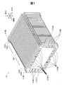
以下、本発明の実施の形態について、図面に基づき説明する。図1は本発明の実施形態としての燃料電池10の構成を示す概略斜視図である。燃料電池10は、燃料電池セルたるユニットセル100をZ方向(以下、「積層方向」とも呼ぶ)に複数積層し、一対のエンドプレート170F,170Eで挟持したスタック構造を有している。燃料電池10は、前端側のエンドプレート170Fとユニットセル100との間に、前端側の絶縁板165Fを介在させて前端側のターミナルプレート160Fを有する。燃料電池10は、後端側のエンドプレート170Eとユニットセル100との間にも、同様に、後端側の絶縁板165Eを介在させて後端側のターミナルプレート160Eを有する。ユニットセル100と、ターミナルプレート160F,160Eと、絶縁板165F,165Eおよびエンドプレート170F,170Eは、それぞれ、略矩形状の外形を有するプレート構造を有しており、長辺がx方向(水平方向)で短辺がy方向(垂直方向,鉛直方向)に沿うように配置されている。   Hereinafter, embodiments of the present invention will be described with reference to the drawings. FIG. 1 is a schematic perspective view showing the configuration of a fuel cell 10 as an embodiment of the present invention. The fuel cell 10 has a stack structure in which a plurality of unit cells 100 as fuel cells are stacked in the Z direction (hereinafter also referred to as “stacking direction”) and sandwiched between a pair of end plates 170F and 170E. The fuel cell 10 has a front end side terminal plate 160F between a front end side end plate 170F and the unit cell 100 with a front end side insulating plate 165F interposed therebetween. Similarly, the fuel cell 10 has a rear end side terminal plate 160E between the rear end side end plate 170E and the unit cell 100 with a rear end side insulating plate 165E interposed therebetween. The unit cell 100, the terminal plates 160F and 160E, the insulating plates 165F and 165E, and the end plates 170F and 170E each have a plate structure having a substantially rectangular outer shape, and the long sides are in the x direction (horizontal direction). ) And the short side is arranged along the y direction (vertical direction, vertical direction).

前端側におけるエンドプレート170Fと絶縁板165Fとターミナルプレート160Fは、燃料ガス供給孔172INおよび燃料ガス排出孔172OTと、複数の酸化剤ガス供給孔174INおよび酸化剤ガス排出孔174OTと、複数の冷却水供給孔176INおよび冷却水排出孔176OTとを有する。これらの給排孔は、各ユニットセル100の対応する位置に設けられているそれぞれの孔(不図示)と連結して、それぞれに対応するガス或いは冷却水の給排マニホールドを構成する。その一方、後端側におけるエンドプレート170Eと絶縁板165Eとターミナルプレート160Eには、これらの給排孔は設けられていない。これは、反応ガス(燃料ガス,酸化剤ガス)および冷却水を前端側のエンドプレート170Fからそれぞれのユニットセル100に対して供給マニホールドを介して供給しつつ、それぞれのユニットセル100からの排出ガスおよび排出水を前端側のエンドプレート170Fから外部に対して排出マニホールドを介して排出するタイプの燃料電池であることによる。ただし、これに限定されるものではなく、例えば、前端側のエンドプレート170Fから反応ガスおよび冷却水を供給し、後端側のエンドプレート170Eから排出ガスおよび排出水が外部へ排出されるタイプ等の種々のタイプとすることができる。   The end plate 170F, the insulating plate 165F, and the terminal plate 160F on the front end side include a fuel gas supply hole 172IN and a fuel gas discharge hole 172OT, a plurality of oxidant gas supply holes 174IN and an oxidant gas discharge hole 174OT, and a plurality of cooling waters. It has a supply hole 176IN and a cooling water discharge hole 176OT. These supply / discharge holes are connected to respective holes (not shown) provided at corresponding positions of the unit cells 100 to constitute gas / cooling water supply / discharge manifolds corresponding to the respective holes. On the other hand, these supply / discharge holes are not provided in the end plate 170E, the insulating plate 165E, and the terminal plate 160E on the rear end side. This is because the reaction gas (fuel gas, oxidant gas) and cooling water are supplied from the front end plate 170F to each unit cell 100 via the supply manifold, while the exhaust gas from each unit cell 100 is discharged. In addition, the fuel cell is a type that discharges discharged water from the front end side end plate 170F to the outside through a discharge manifold. However, the present invention is not limited to this, for example, a type in which reaction gas and cooling water are supplied from the end plate 170F on the front end side, and exhaust gas and discharge water are discharged to the outside from the end plate 170E on the rear end side. Can be of various types.

複数の酸化剤ガス供給孔174INは、前端側のエンドプレート170Fの下端の外縁部にx方向(長辺方向)に沿って配置されており、複数の酸化剤ガス排出孔174OTは、上端の外縁部にx方向に沿って配置されている。燃料ガス供給孔172INは、前端側のエンドプレート170Fの右端の外縁部のy方向(短辺方向)の上端部に配置されており、燃料ガス排出孔172OTは、左端の外縁部のy方向の下端部に配置されている。複数の冷却水供給孔176INは、燃料ガス供給孔172INの下側にy方向に沿って並んで配置されており、複数の冷却水排出孔176OTは、燃料ガス排出孔172OTの上側にy方向に沿って並んで配置されている。そして、冷却水供給孔176INの並びの上側の二つの冷却水供給孔176INは、冷却水排出孔176OTの並びの下側の二つの冷却水排出孔176OTと向き合うように位置し、冷却水供給孔176INと冷却水排出孔176OTとは、その一部がセパレーター中央領域121を挟んでy方向(上下方向)においてオーバーラップしている。   The plurality of oxidant gas supply holes 174IN are arranged along the x direction (long side direction) at the outer edge of the lower end of the front end side end plate 170F, and the plurality of oxidant gas discharge holes 174OT are arranged at the outer edge of the upper end. It is arrange | positioned along the x direction in the part. The fuel gas supply hole 172IN is arranged at the upper end portion in the y direction (short side direction) of the outer edge portion of the right end of the front end side end plate 170F, and the fuel gas discharge hole 172OT is arranged in the y direction of the outer edge portion of the left end. It is arranged at the lower end. The plurality of cooling water supply holes 176IN are arranged along the y direction below the fuel gas supply holes 172IN, and the plurality of cooling water discharge holes 176OT are arranged in the y direction above the fuel gas discharge holes 172OT. They are arranged side by side. The two cooling water supply holes 176IN on the upper side of the row of cooling water supply holes 176IN are positioned so as to face the two cooling water discharge holes 176OT on the lower side of the row of cooling water discharge holes 176OT. A part of 176IN and the cooling water discharge hole 176OT overlap in the y direction (vertical direction) with the separator central region 121 interposed therebetween.

前端側のターミナルプレート160Fおよび後端側のターミナルプレート160Eは、各ユニットセル100の発電電力の集電板であり、図示しない端子から集電した電力を外部へ出力する。   The terminal plate 160F on the front end side and the terminal plate 160E on the rear end side are current collecting plates for the generated power of each unit cell 100, and output the power collected from terminals not shown to the outside.

図2はユニットセル100の構成を分解して示す概略斜視図である。図示するように、ユニットセル100は、膜電極ガス拡散層接合体(MEGA:Membrane Electrode & Gas Diffusion Layer Assembly)110と、MEGA110の両面を挟むように配置されたアノード側セパレーター120と、カソード側セパレーター130と、接着シール140と、ガス流路部材150とを備える。   FIG. 2 is a schematic perspective view showing the structure of the unit cell 100 in an exploded manner. As shown in the figure, the unit cell 100 includes a membrane electrode gas diffusion layer assembly (MEGA) 110, an anode-side separator 120 disposed so as to sandwich both surfaces of the MEGA 110, and a cathode-side separator. 130, an adhesive seal 140, and a gas flow path member 150.

MEGA110は、電解質膜の両面に一対の触媒電極層が形成された膜電極接合体(MEA:Membrane Electrode Assembly)を含み、このMEAをガス拡散透過を図るガス拡散層(Gas Diffusion Layer/GDL)で挟持して構成される発電体である。なお、MEGAをMEAと呼ぶ場合もある。   The MEGA 110 includes a membrane electrode assembly (MEA) in which a pair of catalyst electrode layers are formed on both surfaces of an electrolyte membrane, and this MEA is a gas diffusion layer (Gas Diffusion Layer / GDL) that allows gas diffusion and permeation of the MEA. It is a power generator configured to be sandwiched. Note that MEGA may be referred to as MEA.

アノード側セパレーター120およびカソード側セパレーター130は、ガス遮断性および電子伝導性を有する部材によって構成されており、例えば、カーボン粒子を圧縮してガス不透過とした緻密質カーボン等のカーボン製部材や、プレス成型したステンレス鋼やチタン鋼などの金属部材によって形成されている。本実施形態では、アノード側セパレーター120については、ステンレス鋼をプレス成型して作製した。   The anode-side separator 120 and the cathode-side separator 130 are composed of members having gas barrier properties and electronic conductivity, for example, carbon members such as dense carbon that compresses carbon particles and makes gas impermeate, It is made of a press-molded metal member such as stainless steel or titanium steel. In this embodiment, the anode-side separator 120 was produced by press molding stainless steel.

アノード側セパレーター120は、MEGA110の側の面に、複数筋の溝状の燃料ガス流路を備え、反対側の面に、複数筋の溝状の冷却水流路を備え、この両流路を、セパレーター表裏面で交互に並べている。これら流路については、後述する。このアノード側セパレーター120は、上述したマニホールドを構成する給排孔として、燃料ガス供給孔122INおよび燃料ガス排出孔122OTと、複数の酸化剤ガス供給孔124INおよび酸化剤ガス排出孔124OTと、複数の冷却水供給孔126INおよび冷却水排出孔126OTとを備える。同様に、カソード側セパレーター130は、燃料ガス供給孔132INおよび燃料ガス排出孔132OTと、複数の酸化剤ガス供給孔134INおよび酸化剤ガス排出孔134OTと、複数の冷却水供給孔136INおよび冷却水排出孔136OTとを備える。また、接着シール140にあっても、同様に、アノード側セパレーター120の給排孔に対応して、燃料ガス供給孔142INおよび燃料ガス排出孔142OTと、複数の酸化剤ガス供給孔144INおよび酸化剤ガス排出孔144OTと、複数の冷却水供給孔146INおよび冷却水排出孔146OTとを備える。   The anode separator 120 includes a plurality of grooved fuel gas flow paths on the MEGA 110 side surface, and a plurality of grooved cooling water flow paths on the opposite surface. They are arranged alternately on the front and back of the separator. These flow paths will be described later. The anode-side separator 120 includes a fuel gas supply hole 122IN and a fuel gas discharge hole 122OT, a plurality of oxidant gas supply holes 124IN and an oxidant gas discharge hole 124OT, and a plurality of supply and discharge holes constituting the manifold described above. A cooling water supply hole 126IN and a cooling water discharge hole 126OT are provided. Similarly, the cathode separator 130 includes a fuel gas supply hole 132IN and a fuel gas discharge hole 132OT, a plurality of oxidant gas supply holes 134IN and an oxidant gas discharge hole 134OT, a plurality of cooling water supply holes 136IN and a cooling water discharge. Hole 136OT. Similarly, in the adhesive seal 140, the fuel gas supply hole 142IN and the fuel gas discharge hole 142OT, and the plurality of oxidant gas supply holes 144IN and the oxidant corresponding to the supply / discharge holes of the anode separator 120 are provided. A gas discharge hole 144OT, a plurality of cooling water supply holes 146IN, and a cooling water discharge hole 146OT are provided.

接着シール140は、シール性と絶縁性を有する樹脂或いはゴム等から形成され、その中央に、MEGA110の矩形形状に適合した発電領域窓141を有する。この発電領域窓141の周縁は、段差形状とされており、その段差部に、MEGA110が組み込み装着される。こうして発電領域窓141に装着されたMEGA110は、接着シール140の段差部において接着シール140と重なり、発電領域窓141にて露出した領域を、後述のアノード側セパレーター120から燃料ガスの供給を受ける発電領域112とする。接着シール140は、MEGA110が組み込まれた発電領域窓141の周囲領域に既述した給排孔を備え、MEGA110を発電領域窓141に組み込んだ状態で、アノード側セパレーター120とカソード側セパレーター130とを、それぞれの給排孔回りを含めてシールする。つまり、接着シール140は、段差部でMEGA110をその発電領域112の外側領域に亘ってシールするほか、MEGA110の矩形形状外周面についても、アノード側セパレーター120とカソード側セパレーター130との間でシールする。なお、アノード側およびセパレーター側の両セパレーターは、ユニットセル100が積層された際の燃料ガス、酸化剤ガス、冷却水ごとの給排孔のシール性をセパレーター同士の接合面で確保すべく、後述の図3に示すように燃料ガス用シール材300と、酸化剤用シール材301と、冷却水用シール材302とを備える。   The adhesive seal 140 is formed of a resin or rubber having a sealing property and an insulating property, and has a power generation region window 141 adapted to the rectangular shape of the MEGA 110 at the center thereof. The peripheral edge of the power generation area window 141 has a stepped shape, and the MEGA 110 is assembled and attached to the stepped portion. The MEGA 110 thus mounted on the power generation region window 141 overlaps the adhesive seal 140 at the step portion of the adhesive seal 140, and the region exposed at the power generation region window 141 is supplied with fuel gas from the anode separator 120 described later. Region 112 is assumed. The adhesive seal 140 includes the supply / discharge holes described above in the peripheral region of the power generation region window 141 in which the MEGA 110 is incorporated. , Seal around each supply and discharge hole. That is, the adhesive seal 140 seals the MEGA 110 at the step portion over the outer region of the power generation region 112 and also seals the rectangular outer peripheral surface of the MEGA 110 between the anode side separator 120 and the cathode side separator 130. . Both the anode-side separator and the separator-side separator are described later in order to ensure the sealing performance of the supply / discharge holes for each of the fuel gas, oxidant gas, and cooling water when the unit cells 100 are stacked. As shown in FIG. 3, a fuel gas sealing material 300, an oxidant sealing material 301, and a cooling water sealing material 302 are provided.

ガス流路部材150は、接着シール140を介在させた上で、MEGA110とカソード側セパレーター130との間に位置し、酸化剤ガス供給孔134INから酸化剤ガス排出孔134OTに掛けての酸化剤ガスの流路を形成する。そして、このガス流路部材150は、その部材上下端を、酸化剤ガス供給孔134INの上端と酸化剤ガス排出孔134OTの下端に重なるように延ばしている。このため、ガス流路部材150は、カソード側セパレーター130の酸化剤ガス供給孔134INから供給される酸化剤ガスを部材下端から導き入れ、その導き入れた酸化剤ガスを、MEGA110の面方向(XY平面方向)に沿って流す。そして、ガス流路部材150は、余剰の酸化剤ガスを部材上端から酸化剤ガス排出孔134OTに排出する。このようなガス流路部材150としては、金属多孔体(例えば、エキスパンドメタル)などのガス拡散性および導電性を有する多孔質の材料が用いられる。また、このガス流路部材150は、図2における上下端に、ガス非透過の薄葉状のシーリングシート151を備え、当該シートを、MEGA110の上下端領域に接合させている。   The gas flow path member 150 is located between the MEGA 110 and the cathode-side separator 130 with the adhesive seal 140 interposed therebetween, and the oxidant gas applied from the oxidant gas supply hole 134IN to the oxidant gas discharge hole 134OT. The flow path is formed. The gas flow path member 150 has its upper and lower ends extending so as to overlap the upper end of the oxidant gas supply hole 134IN and the lower end of the oxidant gas discharge hole 134OT. For this reason, the gas flow path member 150 introduces the oxidant gas supplied from the oxidant gas supply hole 134IN of the cathode separator 130 from the lower end of the member, and introduces the introduced oxidant gas into the surface direction (XY) of the MEGA 110. Flow along the plane direction). Then, the gas flow path member 150 discharges excess oxidant gas from the upper end of the member to the oxidant gas discharge hole 134OT. As such a gas flow path member 150, a porous material having gas diffusibility and conductivity such as a metal porous body (for example, expanded metal) is used. Further, the gas flow path member 150 includes gas-impermeable thin leaf-like sealing sheets 151 at the upper and lower ends in FIG. 2, and the sheets are joined to the upper and lower end regions of the MEGA 110.

カソード側セパレーター130は、既述した給排孔の形成領域を含めてほぼ平板状とされ、図2におけるガス流路部材150の上下端近傍に、脚131を、図2における紙面奥側に突出させている。この脚131は、ユニットセル100が積層された際に、隣り合うユニットセル100のアノード側セパレーター120における後述の外縁部123に接触する。この様子については、後述する。   The cathode-side separator 130 has a substantially flat plate shape including the above-described supply / exhaust hole formation region, and the legs 131 protrude in the vicinity of the upper and lower ends of the gas flow path member 150 in FIG. I am letting. When the unit cells 100 are stacked, the legs 131 come into contact with an outer edge portion 123 (described later) in the anode-side separator 120 of the adjacent unit cell 100. This situation will be described later.

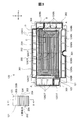
図3はアノード側セパレーター120の構成を示す概略平面図である。この図3は、アノード側セパレーター120に隣接する他のユニットセル100に対向する面(以下、「冷却面」とも呼ぶ)側から見た状態を示している。この冷却面と反対のMEGA110に対向する面を「ガス面」とも呼ぶ。アノード側セパレーター120は、ステンレス鋼等をプレス成型して形成され、図2に示すように、接着シール140とガス流路部材150とを介在させて、MEGA110をカソード側セパレーター130と共に挟持する。このアノード側セパレーター120は、MEGA110の既述した発電領域112と対向するセパレーター中央領域121に、後述の複数筋の第1溝202と第2溝204とを交互に並べて備え、セパレーター中央領域121から外側に延びて当該中央領域を取り囲む平板状の外縁部123に、既述した反応ガスおよび冷却水の給排孔として、燃料ガス供給孔122INおよび燃料ガス排出孔122OTと、複数の酸化剤ガス供給孔124INおよび酸化剤ガス排出孔124OTと、複数の冷却水供給孔126INおよび冷却水排出孔126OTとを備える。これら給排孔のうち、燃料ガス供給孔122INと燃料ガス排出孔122OTとは、燃料ガス用シール材300により個別にシールされ、複数の酸化剤ガス供給孔124INと複数の酸化剤ガス排出孔124OTとは、酸化剤用シール材301により、孔の並びごとシールされる。また、冷却水用シール材302は、複数の冷却水供給孔126INと冷却水排出孔126OT、および冷却面側のセパレーター中央領域121を含む冷却水流通域を取り囲み、この冷却水流通域をシールする。こうした給排孔シールは、カソード側セパレーター130においてもなされている。   FIG. 3 is a schematic plan view showing the configuration of the anode separator 120. FIG. 3 shows a state as viewed from the surface facing the other unit cell 100 adjacent to the anode separator 120 (hereinafter also referred to as “cooling surface”). A surface facing the MEGA 110 opposite to the cooling surface is also referred to as a “gas surface”. The anode-side separator 120 is formed by press-molding stainless steel or the like, and sandwiches the MEGA 110 together with the cathode-side separator 130 with an adhesive seal 140 and a gas flow path member 150 interposed therebetween as shown in FIG. The anode-side separator 120 includes a separator central region 121 facing the power generation region 112 of the MEGA 110 described above, and a plurality of first and second grooves 202 and 204 described later are alternately arranged. A fuel gas supply hole 122IN, a fuel gas discharge hole 122OT, and a plurality of oxidant gas supplies as supply and discharge holes for the reaction gas and cooling water described above are formed in the flat outer edge 123 extending outward and surrounding the central region. A hole 124IN and an oxidant gas discharge hole 124OT, and a plurality of cooling water supply holes 126IN and a cooling water discharge hole 126OT are provided. Of these supply and discharge holes, the fuel gas supply hole 122IN and the fuel gas discharge hole 122OT are individually sealed by the fuel gas sealing material 300, and have a plurality of oxidant gas supply holes 124IN and a plurality of oxidant gas discharge holes 124OT. Is sealed by the oxidant sealing material 301 along the array of holes. The cooling water sealing material 302 surrounds the cooling water circulation area including the plurality of cooling water supply holes 126IN, the cooling water discharge holes 126OT, and the separator central area 121 on the cooling surface side, and seals the cooling water circulation area. . Such a supply / discharge hole seal is also made in the cathode separator 130.

第1溝202は、アノード側セパレーター120の既述したガス面側であって図3においては紙面奥側の面の側で凹な凹溝であり、このガス面において延びる。第2溝204は、アノード側セパレーター120の既述した冷却面側であって図3においては紙面手前側の面の側で凹な凹溝であり、この冷却面において延びる。そして、この第1溝202と第2溝204は、両溝形状に適合した凹凸形状の金型をセパレーター中央領域121に対するプレス押圧するプレス成型による複数筋の凹凸条として形成され、セパレーター中央領域121においてアノード側セパレーター120の表裏面で交互に並ぶ。つまり、アノード側セパレーター120は、図3における縦断面視において、この第1溝202と第2溝204とが交互に繰り返し並んだ断面凸凹形状(断面波形形状)とされている。   The first groove 202 is a concave groove that is concave on the gas surface side of the anode-side separator 120 as described above, and in FIG. 3 on the back surface side of the paper surface, and extends in this gas surface. The second groove 204 is a concave groove on the cooling surface side of the anode-side separator 120 described above, which is a concave groove on the front surface side in FIG. 3, and extends on this cooling surface. Then, the first groove 202 and the second groove 204 are formed as a plurality of streaky ridges by press molding in which a concavo-convex mold adapted to both groove shapes is pressed against the separator central region 121, and the separator central region 121. Are alternately arranged on the front and back surfaces of the anode-side separator 120. That is, the anode-side separator 120 has a cross-sectional uneven shape (cross-sectional corrugated shape) in which the first grooves 202 and the second grooves 204 are alternately and repeatedly arranged in a longitudinal sectional view in FIG.

ガス面側で凹な第1溝202は、接着シール140の発電領域窓141に露出したMEGA110に燃料ガスを供給する燃料ガス流路溝(以下、「燃料ガス流路溝202」とも呼ぶ)を構成し、冷却面側で凹な第2溝204は、燃料ガス流路溝202を仕切るリブを構成するとともに、後述のカソード側セパレーター130にアノード側セパレーター120が接触することで、冷却水が通過する冷却水流路溝(以下、「冷却水流路溝204」とも呼ぶ)を構成する。そして、複数の燃料ガス流路溝202で構成される燃料ガス流路200が、燃料ガス供給孔122INから燃料ガス排出孔122OTへ向けてサーペンタイン状に、図3における紙面裏側の既述したガス面側に形成されている。本実施形態のユニットセル100は、サーペンタイン状の燃料ガス流路200において、図3に示すセパレーター中央領域121の上下端側に位置する燃料ガス流路溝202を、外縁部123の側でセパレーター中央領域121の左右方向、即ち図3におけるx方向に延ばしている。こうすることで、セパレーター中央領域121がMEGA110の発電領域112に対向した場合に、この発電領域112の周縁にも、外縁部123の側でセパレーター中央領域121の左右方向に延びた燃料ガス流路溝202から燃料ガスを供給できる。なお、図3のC部拡大に示すように、セパレーター中央領域121の上下端側に位置して、外縁部123の側でセパレーター中央領域121の左右方向に延びる第1溝202を、セパレーター中央領域121の内側に位置する第1溝202と区別すべく、端部第1溝202tと称することとする。   The first groove 202 that is concave on the gas surface side is a fuel gas passage groove that supplies fuel gas to the MEGA 110 exposed to the power generation area window 141 of the adhesive seal 140 (hereinafter also referred to as “fuel gas passage groove 202”). The second groove 204 that is configured and concave on the cooling surface side constitutes a rib that partitions the fuel gas flow channel groove 202, and the cooling water passes through when the anode separator 120 comes into contact with the cathode separator 130 described later. The cooling water channel groove (hereinafter also referred to as “cooling water channel groove 204”) is configured. Then, the fuel gas flow path 200 constituted by the plurality of fuel gas flow path grooves 202 is formed in a serpentine shape from the fuel gas supply hole 122IN to the fuel gas discharge hole 122OT, and the gas surface described above on the back side of the paper in FIG. Formed on the side. The unit cell 100 of the present embodiment includes a serpentine-shaped fuel gas flow channel 200 in which a fuel gas flow channel groove 202 positioned on the upper and lower ends of the separator central region 121 shown in FIG. The region 121 extends in the left-right direction, that is, the x direction in FIG. In this way, when the separator central region 121 faces the power generation region 112 of the MEGA 110, the fuel gas flow path extending in the left-right direction of the separator central region 121 on the outer edge 123 side also on the periphery of the power generation region 112 Fuel gas can be supplied from the groove 202. 3, the first groove 202 that is positioned on the upper and lower ends of the separator central region 121 and extends in the left-right direction of the separator central region 121 on the outer edge portion 123 side is provided in the separator central region. In order to distinguish from the 1st groove | channel 202 located inside 121, it shall call the edge part 1st groove | channel 202t.

燃料ガス流路溝202は、サーペンタイン状の溝経路を採ることから、図3に示すセパレーター中央領域121の左右の水平端側領域である転換領域Aでは、溝経路向きをx方向からy方向に、或いはこの逆にx方向からy方向に変えると共に、燃料ガス供給孔122INおよび燃料ガス排出孔122OTの近傍では溝経路向きを斜めに変える。そして、第1溝202は、この転換領域Aを含め、x方向に延びる直線流路域において、冷却面側において、冷却水流路溝204を仕切るリブとして機能する。燃料ガス流路溝202は、x方向に延びる直線流路域において冷却水流路溝204を仕切るリブとして機能するとはいえ、冷却水排出孔126OTの側へ向かう第2溝204での冷却水の流れを阻害しない。ところが、溝経路向きが変換する転換領域Aでは、燃料ガス流路溝202が壁となって、冷却水供給孔126INから冷却水排出孔126OTへ向かう冷却水の流れが阻害され得る。そこで、この領域の燃料ガス流路溝202を以下で説明する構造とすることにより、これを防止している。   Since the fuel gas channel groove 202 takes a serpentine-like groove path, the groove path direction is changed from the x direction to the y direction in the conversion area A which is the left and right horizontal end area of the separator central area 121 shown in FIG. Or, conversely, the x direction is changed to the y direction, and the groove path direction is changed obliquely in the vicinity of the fuel gas supply hole 122IN and the fuel gas discharge hole 122OT. The first groove 202 functions as a rib that partitions the cooling water flow channel groove 204 on the cooling surface side in the linear flow channel region extending in the x direction including the conversion region A. Although the fuel gas channel groove 202 functions as a rib that partitions the cooling water channel groove 204 in the linear channel region extending in the x direction, the flow of the cooling water in the second groove 204 toward the cooling water discharge hole 126OT. Does not disturb. However, in the conversion region A in which the groove path direction changes, the fuel gas flow channel groove 202 serves as a wall, and the flow of the cooling water from the cooling water supply hole 126IN to the cooling water discharge hole 126OT can be hindered. Therefore, this is prevented by adopting the structure described below for the fuel gas passage groove 202 in this region.

図4は図3に示した転換領域Aに含まれる冷却水供給孔周辺領域Bにおける流路溝の形成状況を拡大して示す概略斜視図である。図4において、紙面手前側が冷却面側であり、紙面奥側がガス面側である。y方向に沿って形成された燃料ガス流路溝202には、浅溝部208が点在形成されている。浅溝部208は、他の部分(以下、「深溝部206」とも呼ぶ)よりも深さが浅い部分である。ここで、燃料ガス流路溝202の深さとは、アノード側セパレーター120のガス面のMEGA110に接触する部分の位置から、燃料ガス流路溝202の底部までの距離を意味する。従って、燃料ガス流路溝202の深さは、深溝部206の位置において深く、浅溝部208の位置において浅くなるものの、深溝部206と浅溝部208は、図3の転換領域Aにおける燃料ガス流路溝202の溝経路に沿って交互に並んでいるが、いずれも、MEGA110とは接触しない。よって、燃料ガス流路溝202は、図3の転換領域Aにおいてもその流路溝経路に沿って燃料ガスを通過させる。この場合、深溝部206の深さは、転換領域A以外の流路溝経路(燃料ガス流路200:図3参照)における燃料ガス流路溝202と同じとされている。   FIG. 4 is a schematic perspective view showing, in an enlarged manner, the formation state of the flow channel grooves in the cooling water supply hole peripheral region B included in the conversion region A shown in FIG. In FIG. 4, the front side of the paper surface is the cooling surface side, and the back surface of the paper surface is the gas surface side. Shallow grooves 208 are dotted in the fuel gas flow channel 202 formed along the y direction. The shallow groove portion 208 is a portion having a shallower depth than other portions (hereinafter also referred to as “deep groove portion 206”). Here, the depth of the fuel gas flow channel 202 means the distance from the position of the portion of the gas surface of the anode separator 120 in contact with the MEGA 110 to the bottom of the fuel gas flow channel 202. Therefore, although the depth of the fuel gas flow channel groove 202 is deep at the position of the deep groove portion 206 and becomes shallow at the position of the shallow groove portion 208, the deep groove portion 206 and the shallow groove portion 208 are different in the fuel gas flow in the conversion region A of FIG. Although they are alternately arranged along the groove path of the road groove 202, none of them is in contact with the MEGA 110. Therefore, the fuel gas channel groove 202 allows the fuel gas to pass along the channel groove path also in the conversion region A of FIG. In this case, the depth of the deep groove portion 206 is the same as that of the fuel gas flow path groove 202 in the flow path groove path (fuel gas flow path 200: see FIG. 3) other than the conversion region A.

また、複数のユニットセル100が積層された燃料電池10(図1,2参照)において、アノード側セパレーター120は、隣接するユニットセル100のカソード側セパレーター130の表面に、各深溝部206の底部壁202sの外周面、図4の図示では天井面を接触させ、浅溝部208の位置ではカソード側セパレーター130に接触させない。このため、アノード側セパレーター120の浅溝部208の位置の冷却面側には、カソード側セパレーター130の表面との間に、浅溝部208を挟んで隣接する2つの冷却水流路溝204を連通する連通流路溝205が複数形成される。この連通流路溝205は、冷却水供給孔126INの側から延びてy方向に延びた冷却水流路溝204と交差するようになる。この構造によって、冷却水は、冷却水流路溝204に沿ってy方向に流れるだけでなく、連通流路溝205を介してx方向にも流れるようにすることが可能となる。つまり、連通流路溝205は、隣り合う冷却水流路溝204における冷却水の通過を許容するので、隣り合う冷却水流路溝204の間の冷却水流通が起きる。これにより、転換領域Aにおいて、x方向に沿って延びる冷却水流路溝204を流れる冷却水は、y方向に沿って延びる燃料ガス流路溝202によってその流れが遮断されずに、冷却水流路溝204に沿って、或いは隣り合う冷却水流路溝204の間に亘って流れる。図4に示す冷却水供給孔周辺領域Bでy方向に延びる冷却水流路溝204は、図3に示すように、やがてx方向に延び、このx方向に延びる範囲においては、溝経路に沿って冷却水を流す。   In the fuel cell 10 (see FIGS. 1 and 2) in which a plurality of unit cells 100 are stacked, the anode separator 120 is formed on the surface of the cathode separator 130 of the adjacent unit cell 100 on the bottom wall of each deep groove 206. The outer peripheral surface of 202 s, the ceiling surface in the illustration of FIG. 4, is brought into contact, and the cathode-side separator 130 is not contacted at the position of the shallow groove portion 208. For this reason, on the cooling surface side at the position of the shallow groove portion 208 of the anode side separator 120, communication is established between the surface of the cathode side separator 130 and the two adjacent cooling water passage grooves 204 with the shallow groove portion 208 interposed therebetween. A plurality of flow channel grooves 205 are formed. This communication channel groove 205 extends from the cooling water supply hole 126IN side and intersects with the cooling water channel groove 204 extending in the y direction. With this structure, the cooling water can flow not only in the y direction along the cooling water channel groove 204 but also in the x direction via the communication channel groove 205. That is, the communication flow channel 205 allows the cooling water to pass through the adjacent cooling water flow channel 204, so that cooling water flows between the adjacent cooling water flow channels 204. Thereby, in the conversion area A, the cooling water flowing through the cooling water passage groove 204 extending along the x direction is not blocked by the fuel gas passage groove 202 extending along the y direction. It flows along 204 or between adjacent cooling water flow path grooves 204. As shown in FIG. 3, the cooling water flow channel groove 204 extending in the y direction in the cooling water supply hole peripheral region B shown in FIG. 4 eventually extends in the x direction, and in the range extending in the x direction, along the groove path. Pour cooling water.

また、図示は省略するが、図3に示した転換領域Aのx方向に沿った燃料ガス流路溝202にも同様に浅溝部208が点在形成される。これにより、y方向に沿って延びる燃料ガス流路溝202に平行な冷却水流路溝204を流れる冷却水は、x方向に沿って延びる燃料ガス流路溝202によってその流れが遮断されない。この他、x方向およびy方向に沿った燃料ガス流路溝202だけでなく、転換領域Aにおいて溝経路向きがx方向およびy方向に対して斜めに変わる燃料ガス流路溝202に対しても同様に浅溝部208が点在形成される。これにより、溝経路向きがx方向およびy方向に対して斜めに延びる燃料ガス流路溝202に平行な冷却水流路溝204を流れる冷却水は、冷却水流路溝204の両隣で斜めに延びる燃料ガス流路溝202によって、その流れが遮断されない。従って、アノード側セパレーター120は、冷却水供給孔126INから供給される冷却水を、x方向およびy方向のいずれの方向に沿った燃料ガス流路溝202によっても遮断させずに、冷却水排出孔126OTへ向けて流すことが可能である。つまり、冷却水は、冷却水流路溝204を流れる冷却水と燃料ガス流路溝202を流れる冷却水の合流の結果、その流れの向きを変えつつ冷却水供給孔周辺領域Bのみならず、転換領域Aの全域において流れる。   Although not shown, shallow grooves 208 are similarly formed in the fuel gas passage grooves 202 along the x direction of the conversion region A shown in FIG. As a result, the flow of the cooling water flowing through the cooling water channel groove 204 parallel to the fuel gas channel groove 202 extending along the y direction is not blocked by the fuel gas channel groove 202 extending along the x direction. In addition to the fuel gas flow channel groove 202 along the x direction and the y direction, the fuel gas flow channel groove 202 in which the direction of the groove path changes obliquely with respect to the x direction and the y direction in the conversion region A Similarly, the shallow grooves 208 are formed in a dotted manner. As a result, the cooling water flowing through the cooling water passage groove 204 parallel to the fuel gas passage groove 202 whose groove passage direction extends obliquely with respect to the x direction and the y direction is obliquely extended on both sides of the cooling water passage groove 204. The flow is not blocked by the gas flow path groove 202. Therefore, the anode-side separator 120 does not block the cooling water supplied from the cooling water supply hole 126IN by the fuel gas passage groove 202 along either the x direction or the y direction, and the cooling water discharge hole It is possible to flow toward 126 OT. In other words, as a result of the merging of the cooling water flowing through the cooling water flow channel groove 204 and the cooling water flowing through the fuel gas flow channel groove 202, the cooling water is changed not only in the cooling water supply hole peripheral region B while changing the flow direction. It flows in the entire area A.

アノード側セパレーター120は、燃料ガス流路溝202を図3の転換領域Aにおいてはその溝経路に沿って深溝部206と浅溝部208を交互に並べて備える。その一方、アノード側セパレーター120は、サーペンタイン状の溝経路における直線経路、即ち図3におけるx方向では、ガス面側の端部第1溝202tを含む他の燃料ガス流路溝202と、冷却水側の冷却水流路溝204とを、単純な凹溝形状としている。   The anode-side separator 120 includes the fuel gas flow channel grooves 202 alternately arranged in the deep groove portions 206 and the shallow groove portions 208 along the groove paths in the conversion region A of FIG. On the other hand, the anode-side separator 120 has a linear path in the serpentine-shaped groove path, that is, in the x direction in FIG. 3, other fuel gas flow path grooves 202 including the gas surface side end first grooves 202t, and cooling water The cooling water passage groove 204 on the side has a simple concave groove shape.

また、アノード側セパレーター120は、図4に示すように、案内凸部127と供給孔間凸部128とを備える。案内凸部127は、冷却水供給孔126INとセパレーター中央領域121(図3参照)との間において、セパレーター中央領域121に対して傾斜して冷却面側に突出し、平面状の頂上面を有する。供給孔間凸部128は、案内凸部127から供給孔間に延びる形状で冷却面側に突出し、平面状の頂上面を有する。この案内凸部127と供給孔間凸部128とは、その頂上面の高さが深溝部206の底部壁202sと同じとなるように冷却面側に突出している。よって、アノード側セパレーター120が後述のカソード側セパレーター130に接触することで、案内凸部127と供給孔間凸部128とは、その頂上面をカソード側セパレーター130に密着させて両セパレーターの間に冷却水流通域を形成し、冷却水供給孔126INからの冷却水を案内しつつ、冷却水流路溝204および連通流路溝205に冷却水を導き入れる整流機能を発揮する。   Further, as shown in FIG. 4, the anode side separator 120 includes a guide convex portion 127 and a supply hole convex portion 128. The guide convex portion 127 is inclined with respect to the separator central region 121 and protrudes toward the cooling surface between the cooling water supply hole 126IN and the separator central region 121 (see FIG. 3), and has a flat top surface. The inter-supply hole convex portion 128 protrudes from the guide convex portion 127 to the cooling surface side in a shape extending between the supply holes, and has a flat top surface. The guide convex portion 127 and the supply hole convex portion 128 protrude toward the cooling surface such that the top surface has the same height as the bottom wall 202 s of the deep groove portion 206. Therefore, when the anode-side separator 120 comes into contact with the cathode-side separator 130, which will be described later, the guide convex portion 127 and the inter-supply-hole convex portion 128 have their top surfaces in close contact with the cathode-side separator 130 and between the separators. A cooling water circulation region is formed, and a rectifying function for introducing the cooling water into the cooling water channel groove 204 and the communication channel groove 205 is exhibited while guiding the cooling water from the cooling water supply hole 126IN.

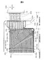
図5は図3に示した転換領域Aに含まれる燃料ガス供給孔周辺領域Dにおける流路溝の形成状況を冷却面側から平面視して拡大して示す説明図である。この図5においても、紙面手前側が冷却面側であり、紙面奥側がガス面側である。   FIG. 5 is an explanatory view showing, in plan view, from the cooling surface side, the state of formation of the flow channel grooves in the fuel gas supply hole peripheral region D included in the conversion region A shown in FIG. Also in FIG. 5, the front side of the paper surface is the cooling surface side, and the back surface of the paper surface is the gas surface side.

図5に示すように、燃料ガス供給孔122INに繋がる燃料ガス入口側領域では、セパレーター中央領域121(図3参照)において燃料ガス流路溝202が水平(x方向)に延びる内部流路部210と、連結流路部220と導入流路部230とで構成される。導入流路部230は、燃料ガス供給孔122INに繋がる流路域であり、連結流路部220は、燃料ガス供給孔122INから導入流路部230を経由して流れてきた燃料ガスを内部流路部210の各ガス流路に受け渡す流路域であり、図示するように、x方向に延びた後に傾斜し、再度、x方向に延びる流路域である。つまり、この連結流路部220は、内部流路部210に属する燃料ガス流路溝202からなる燃料ガス流路部分200aに繋がるようx方向に延びる第1連結流路部分200bと、第1連結流路部分200bに繋がる傾斜した第2連結流路部分200cと、第2連結流路部分200cに繋がってx方向に延びる第3連結流路部分200dと、第3連結流路部分200dと導入流路部230とを連結する境界流路溝202eとで構成されている。   As shown in FIG. 5, in the fuel gas inlet side region connected to the fuel gas supply hole 122IN, the internal channel portion 210 in which the fuel gas channel groove 202 extends horizontally (x direction) in the separator central region 121 (see FIG. 3). And a connecting channel portion 220 and an introduction channel portion 230. The introduction flow path section 230 is a flow path area connected to the fuel gas supply hole 122IN, and the connection flow path section 220 internally flows the fuel gas flowing from the fuel gas supply hole 122IN via the introduction flow path section 230. As shown in the figure, it is a flow passage area that is transferred to each gas flow passage of the passage portion 210, is inclined after extending in the x direction, and again extends in the x direction. That is, the connecting channel portion 220 includes a first connecting channel portion 200b extending in the x direction so as to be connected to the fuel gas channel portion 200a including the fuel gas channel groove 202 belonging to the inner channel portion 210, and the first connecting channel portion 220b. An inclined second connecting channel portion 200c connected to the channel portion 200b, a third connecting channel portion 200d connected to the second connecting channel portion 200c and extending in the x direction, a third connecting channel portion 200d and an introduction flow It is comprised by the boundary flow-path groove | channel 202e which connects the path part 230. FIG.

第1連結流路部分200bは、燃料ガス流路部分200aの複数の燃料ガス流路溝202aに繋がり、x方向に延びる複数の第1連結流路溝202bで構成されている。第2連結流路部分200cは、第1連結流路溝202bから重力方向に傾斜した方向に沿って下方向に向かって延びる複数の第2連結流路溝202c(以下、傾斜ガス流路溝部202cとも呼ぶ)で構成されている。この第2連結流路溝202cは、重力方向に対して傾いた方向(例えば斜め下方向)に沿って下方に延びていることが好ましいが、重力方向に延びていても良い。第3連結流路部分200dは、境界流路溝202eおよび第2連結流路溝202cに繋がり、x方向に延びる複数の第3連結流路溝202dで構成されている。境界流路溝202eは、第3連結流路部分200dと導入流路部230との境界でy方向に沿って延びる溝で構成されている。なお、連結流路部220を構成する各連結流路溝202b,202c,202dは、図4に示した燃料ガス流路溝と同様に、深溝部206と浅溝部208をそれぞれの溝経路に沿って交互に点在させて備え、冷却面側において冷却水を流す図4の連通流路溝205相当の連通流路溝を、隣り合う冷却水流路溝204において構成する。   The first connection channel portion 200b is composed of a plurality of first connection channel grooves 202b that are connected to the plurality of fuel gas channel grooves 202a of the fuel gas channel portion 200a and extend in the x direction. The second connection channel portion 200c includes a plurality of second connection channel grooves 202c (hereinafter, inclined gas channel grooves 202c) extending downward from the first connection channel groove 202b along a direction inclined in the gravitational direction. Also called). The second connection channel groove 202c preferably extends downward along a direction inclined with respect to the direction of gravity (for example, obliquely downward), but may extend in the direction of gravity. The third connection channel portion 200d is composed of a plurality of third connection channel grooves 202d that are connected to the boundary channel groove 202e and the second connection channel groove 202c and extend in the x direction. The boundary flow path groove 202e is configured by a groove extending along the y direction at the boundary between the third connection flow path portion 200d and the introduction flow path portion 230. In addition, each connection channel groove 202b, 202c, 202d which comprises the connection channel part 220 is made into the deep groove part 206 and the shallow groove part 208 along each groove path | route similarly to the fuel gas channel groove | channel shown in FIG. The communication flow channel grooves corresponding to the communication flow channel grooves 205 in FIG. 4 are provided in the adjacent cooling water flow channel grooves 204 so that the cooling water flows on the cooling surface side.

導入流路部230は、境界流路溝202eに繋がる第1導入流路部分230Aと、第1導入流路部分230Aおよび燃料ガス供給孔122INに繋がる第2導入流路部分230Bとで構成されている。これらの導入流路部分230A,230Bは、アノード側セパレーター120のガス面との間に配置されたシーリングプレート129と、アノード側セパレーター120との間に形成されている。第1導入流路部分230Aは、境界流路溝202eに繋がり、略くし歯状流路を構成する複数の第1導出流路溝232Aで構成されている。また、第2導入流路部分230Bは、シーリングプレート129に形成された略くし歯状の凸部234Bによって形成され、略くし歯状流路を構成する。   The introduction flow path section 230 includes a first introduction flow path portion 230A connected to the boundary flow groove 202e, and a second introduction flow path portion 230B connected to the first introduction flow path portion 230A and the fuel gas supply hole 122IN. Yes. These introduction flow path portions 230 </ b> A and 230 </ b> B are formed between the sealing plate 129 disposed between the gas surface of the anode side separator 120 and the anode side separator 120. The first introduction flow path portion 230A is connected to the boundary flow path groove 202e and includes a plurality of first lead-out flow path grooves 232A constituting a substantially comb-shaped flow path. The second introduction channel portion 230B is formed by a substantially comb-like convex portion 234B formed on the sealing plate 129, and constitutes a substantially comb-like channel.

なお、図示および説明を省略するが、燃料ガス流路200のうち燃料ガス排出孔122OTに繋がる出口側領域も、上記した入口側領域と同様に、燃料ガス排出孔122OTに繋がる導入流路部、および、導入流路部と内部流路部との間の連結流路部とで構成されている。   In addition, although illustration and description are omitted, the outlet side region connected to the fuel gas discharge hole 122OT in the fuel gas channel 200 is similar to the above-described inlet side region, and the introduction channel portion connected to the fuel gas discharge hole 122OT, And it is comprised by the connection flow path part between an introductory flow path part and an internal flow path part.

冷却水流路溝204は、上記した燃料ガス流路部分200a〜202dの間に形成されており、第2連結流路溝202cの形成領域には、溝経路方向において、見かけ上、閉塞した冷却水流路溝204が形成されている。しかしながら、図4で説明したように、隣り合う冷却水流路溝204において、冷却水の通過を許容する連通流路溝205が、それぞれの燃料ガス流路溝202における深溝部206と浅溝部208とにより数多く形成されていることから、隣り合う冷却水流路溝204の間の冷却水流通により、冷却水は、溝経路方向で閉鎖した冷却水流路溝204にも入り込み、当該冷却水流路溝に沿って流れる。   The cooling water flow channel 204 is formed between the fuel gas flow channel parts 200a to 202d described above, and the cooling water flow apparently blocked in the groove channel direction in the formation region of the second connection flow channel groove 202c. A road groove 204 is formed. However, as described with reference to FIG. 4, in the adjacent cooling water channel grooves 204, the communication channel grooves 205 that allow the passage of the cooling water are the deep groove portions 206 and the shallow groove portions 208 in the respective fuel gas channel grooves 202. Therefore, the cooling water flows between the adjacent cooling water flow channel grooves 204, so that the cooling water also enters the cooling water flow channel grooves 204 closed in the direction of the groove path, along the cooling water flow channel grooves. Flowing.

本実施形態のアノード側セパレーター120は、図3に示すセパレーター中央領域121の左右両端の転換領域Aにおいて、図4〜図5で説明した溝形態を有することから、冷却水供給孔126INから冷却水排出孔126OTに掛けて、次のように冷却水を通過させる。図6はアノード側セパレーター120における冷却面側での冷却水の流れの様子を模式的に示す説明図である。図示するように、冷却水供給孔126INの各供給孔から供給された冷却水は、連通流路溝205を経由して供給孔側の転換領域Aの冷却水流路溝204に入り込む。この際の冷却水の流れは、案内凸部127と供給孔間凸部128(図4参照)での整流を受けるので、アノード側セパレーター120の図における右方下端側に位置する冷却水供給孔126INから概ね斜め上方に向けた流れとなる。   Since the anode-side separator 120 of the present embodiment has the groove shape described in FIGS. 4 to 5 in the conversion regions A at the left and right ends of the separator central region 121 shown in FIG. 3, the cooling water is supplied from the cooling water supply hole 126IN. The cooling water is passed through the discharge hole 126OT as follows. FIG. 6 is an explanatory diagram schematically showing the flow of cooling water on the cooling surface side in the anode-side separator 120. As shown in the figure, the cooling water supplied from each supply hole of the cooling water supply hole 126IN enters the cooling water flow path groove 204 in the conversion area A on the supply hole side via the communication flow path groove 205. The flow of the cooling water at this time undergoes rectification at the guide convex portion 127 and the convex portion 128 between the supply holes (see FIG. 4), so the cooling water supply hole located on the lower right side of the anode side separator 120 in the drawing. The flow is generally obliquely upward from 126IN.

転換領域Aには、隣り合う冷却水流路溝204の間の冷却水通過を許容する連通流路溝205(図4参照)が形成済みであるので、全体としての冷却水の流れは、転換領域Aにおいて冷却水排出孔126OTの側に向かう水平方向に転ずる。つまり、アノード側セパレーター120は、深溝部206と浅溝部208の点在配置の結果としての連通流路溝205による上記した冷却水の流れを起こす。これに加え、アノード側セパレーター120は、セパレーター中央領域121(図3参照)の上下方向に亘って水平に延びるそれぞれの冷却水流路溝204に冷却水供給孔126INから冷却水を導入するに当たり、燃料ガス供給孔122INの側の転換領域Aにおいて、案内凸部127と供給孔間凸部128、燃料ガス流路溝202に点在配置した深溝部206と浅溝部208により、外縁部123の冷却水供給孔126INから供給された冷却水を、その流れの向きを変えつつ、それぞれの冷却水流路溝204の溝内に拡散導入する。この場合、セパレーター中央領域121の燃料ガス供給孔122INの側のコーナー部、即ち、セパレーター中央領域121の上端側であって且つ冷却水供給孔126INの側のセパレーター中央領域コーナー部の周辺では、セパレーター中央領域121の上端の側に向けた冷却水の流れが起きる。   Since the communication channel groove 205 (see FIG. 4) that allows passage of the cooling water between the adjacent cooling water channel grooves 204 has already been formed in the conversion region A, the flow of the cooling water as a whole In A, it rolls in the horizontal direction toward the cooling water discharge hole 126OT. That is, the anode-side separator 120 causes the above-described flow of cooling water through the communication flow path grooves 205 as a result of the interspersed arrangement of the deep groove portions 206 and the shallow groove portions 208. In addition to this, the anode-side separator 120 uses fuel to introduce cooling water from the cooling water supply holes 126IN into the respective cooling water passage grooves 204 extending horizontally across the vertical direction of the separator central region 121 (see FIG. 3). In the conversion area A on the gas supply hole 122IN side, the cooling water for the outer edge 123 is formed by the guide protrusion 127, the supply hole protrusion 128, and the deep grooves 206 and the shallow grooves 208 that are interspersed in the fuel gas passage groove 202. The cooling water supplied from the supply holes 126IN is diffused and introduced into the grooves of the respective cooling water passage grooves 204 while changing the flow direction. In this case, in the corner portion on the fuel gas supply hole 122IN side of the separator central region 121, that is, on the upper end side of the separator central region 121 and around the separator central region corner portion on the cooling water supply hole 126IN side, The flow of the cooling water toward the upper end side of the central region 121 occurs.

冷却水供給孔126INの側の転換領域Aに続く燃料ガス流路200は、当該流路を構成するそれぞれの燃料ガス流路溝202は、図における水平方向(x方向)に沿って延びている。よって、転換領域Aで水平方向に転じた冷却水は、燃料ガス流路溝202に沿って水平方向に流れる。そして、冷却水排出孔126OTの側の転換領域Aでは、既述した連通流路溝205により、全体としての冷却水の流れ方向が、水平方向からそれぞれの冷却水排出孔126OTに向けた方向となり、アノード側セパレーター120は、冷却水を案内凸部127と供給孔間凸部128(図4参照)とで整流しながら、冷却水流路溝204の溝内から冷却水を燃料ガス排出孔122OTに導く。   In the fuel gas channel 200 following the conversion area A on the cooling water supply hole 126IN side, each fuel gas channel groove 202 constituting the channel extends along the horizontal direction (x direction) in the figure. . Therefore, the cooling water turned in the horizontal direction in the conversion area A flows in the horizontal direction along the fuel gas passage groove 202. In the conversion area A on the cooling water discharge hole 126OT side, the flow direction of the cooling water as a whole is a direction from the horizontal direction toward each cooling water discharge hole 126OT by the communication flow path groove 205 described above. The anode separator 120 rectifies the cooling water between the guide protrusion 127 and the supply hole-to-supply hole protrusion 128 (see FIG. 4), while cooling the cooling water from the groove of the cooling water passage groove 204 to the fuel gas discharge hole 122OT. Lead.

次に、セパレーター中央領域121の燃料ガス供給孔122INの側のコーナー部における流路構成について詳述する。図7は図5に示す燃料ガス供給孔122INの側のセパレーター中央領域121のコーナー部DCにおける流路溝の形成状況を冷却面側から平面視して更に拡大して示す説明図、図8はセパレーター中央領域121のコーナー部DCにおける流路溝の形成状況を冷却面側から見て拡大して示す概略斜視図である。   Next, the flow path configuration at the corner portion on the fuel gas supply hole 122IN side of the separator central region 121 will be described in detail. FIG. 7 is an explanatory diagram showing the flow channel groove formation state in the corner portion DC of the separator central region 121 on the fuel gas supply hole 122IN side shown in FIG. It is a schematic perspective view which expands and shows the formation condition of the flow-path groove | channel in the corner part DC of the separator center area | region 121 seeing from the cooling surface side.

図示するように、アノード側セパレーター120は、セパレーター中央領域121の上端において水平方向(x方向)に延びる端部第1溝202tに陥没コーナー凹所202tbを有する。この陥没コーナー凹所202tbは、燃料ガス流路溝202に設けた浅溝部208と同様、端部第1溝202tにおける他の部分よりも深さが浅くされている。図7では、深さの浅い浅溝部208と陥没コーナー凹所202tbについては、その位置をハッチングにて示している。そして、陥没コーナー凹所202tbは、浅溝部208と同様にMEGA110とは接触しないので、ガス面側の端部第1溝202tは、その流路溝経路に沿って燃料ガスをx方向に通過させる。また、アノード側セパレーター120は、この陥没コーナー凹所202tbの外周面、図8の図示では天井面を浅溝部208と同様にカソード側セパレーター130に接触させない。よって、この陥没コーナー凹所202tbは、図7において端部第1溝202tの下方でx方向に延びる冷却水流路溝204と、端部第1溝202tより上方の外縁部123とを連通する。これにより、端部第1溝202tの下方の冷却水流路溝204にまで流れ込んだ冷却水は、陥没コーナー凹所202tbを経て、セパレーター中央領域121の外縁の外縁部123の側に通過可能となる。   As illustrated, the anode-side separator 120 has a recessed corner recess 202tb in an end first groove 202t extending in the horizontal direction (x direction) at the upper end of the separator central region 121. Similar to the shallow groove 208 provided in the fuel gas flow channel 202, the depression corner recess 202tb is shallower than the other portions of the end first groove 202t. In FIG. 7, the positions of the shallow groove portion 208 and the recessed corner recess 202 tb having a shallow depth are indicated by hatching. Since the recessed corner recess 202tb does not contact the MEGA 110 in the same manner as the shallow groove portion 208, the gas surface side end first groove 202t allows the fuel gas to pass in the x direction along the flow path groove path. . Further, the anode-side separator 120 does not contact the outer peripheral surface of the depression corner recess 202tb, and the ceiling surface in the illustration of FIG. Therefore, the depression corner recess 202tb communicates the cooling water passage groove 204 extending in the x direction below the end first groove 202t and the outer edge 123 above the end first groove 202t in FIG. Thereby, the cooling water that has flown into the cooling water flow path groove 204 below the first end groove 202t can pass through the depression corner recess 202tb to the outer edge 123 side of the outer edge of the separator central region 121. .

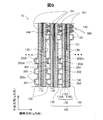
次に、燃料電池10におけるユニットセル100の積層の様子を説明する。図9は図3のC部拡大箇所における9−9線に沿った燃料電池10の概略断面である。図示するように、燃料電池10は、複数のユニットセル100を積層して構成され、ユニットセル100は、MEGA110をアノード側セパレーター120とカソード側セパレーター130とで挟持する。なお、この図9では、MEGA110は、電解質膜の両膜面に触媒電極層を接合したMEA110Dをアノード側ガス拡散層110Aとカソード側ガス拡散層110Cで挟持した形態で示されている。そして、それぞれのユニットセル100は、アノード側セパレーター120がセパレーター中央領域121の外側に延ばして備える外縁部123(図2〜図3参照)を、MEGA110の発電領域112(図2〜図3参照)の周縁において、MEGA110に接合させる。また、それぞれのユニットセル100は、第1溝202と第2溝204が形成済みのセパレーター中央領域121をMEGA110の発電領域112に対向させて接合する。これにより、端部第1溝202tと他の部位の第1溝202は、その凹溝開口端がMEGA110で閉塞され、既述したように延びる燃料ガス流路溝202として機能する。   Next, how the unit cells 100 are stacked in the fuel cell 10 will be described. FIG. 9 is a schematic cross-sectional view of the fuel cell 10 taken along the line 9-9 in the enlarged portion C of FIG. As illustrated, the fuel cell 10 is configured by stacking a plurality of unit cells 100, and the unit cell 100 sandwiches the MEGA 110 between an anode-side separator 120 and a cathode-side separator 130. In FIG. 9, the MEGA 110 is shown in a form in which an MEA 110D having a catalyst electrode layer bonded to both membrane surfaces of the electrolyte membrane is sandwiched between the anode-side gas diffusion layer 110A and the cathode-side gas diffusion layer 110C. Each unit cell 100 includes an outer edge portion 123 (see FIGS. 2 to 3) provided by the anode separator 120 extending outside the separator central region 121, and a power generation region 112 (see FIGS. 2 to 3) of the MEGA 110. Are joined to the MEGA 110 at the periphery. Further, each unit cell 100 is joined with the separator central region 121 in which the first groove 202 and the second groove 204 are formed facing the power generation region 112 of the MEGA 110. As a result, the end first groove 202t and the first groove 202 in another part function as the fuel gas flow channel 202 extending as described above, with the concave groove opening end closed by the MEGA 110.

隣り合って積層されたユニットセル100は、一方のユニットセル100のアノード側セパレーター120が有する第1溝202の底部壁202sを、他方のユニットセル100のカソード側セパレーター130に接触させる。これにより、第2溝204は、その凹溝開口端が閉塞され、既述したように延びる冷却水流路溝204として機能する。また、隣り合って積層されたユニットセル100は、一方のユニットセル100のカソード側セパレーター130が有する脚131を、他方のユニットセル100のアノード側セパレーター120の外縁部123に接触させる。これにより、脚131は、アノード側セパレーター120の外縁部123において、それぞれのユニットセル100の支えとして機能する。この他、隣り合って積層されたユニットセル100は、燃料ガス供給孔122INと冷却水流路溝204が開口した側の冷却面側におけるセパレーター中央領域121と燃料ガス排出孔122OTとを含む冷却水流通域を取り囲む冷却水用シール材302(図3参照)と、酸化剤ガス排出孔124OTを取り囲む酸化剤用シール材301とを、セパレーター上端側において、一方のユニットセル100のアノード側セパレーター120と他方のユニットセル100のカソード側セパレーター130との間に挟持する。なお、セパレーター下端側では、冷却水用シール材302と、酸化剤ガス供給孔124INを取り囲む酸化剤用シール材301とが、セパレーター左右両端では、冷却水用シール材302と、燃料ガス供給孔122INを取り囲む燃料ガス用シール材300および燃料ガス排出孔122OTを取り囲む燃料ガス用シール材300とが、一方のユニットセル100のアノード側セパレーター120と他方のユニットセル100のカソード側セパレーター130とで挟持される。このようにユニットセル100を積層した燃料電池10は、図示しない締結シャフト等にて、セル積層方向に締結される。 In the unit cells 100 stacked adjacent to each other, the bottom wall 202 s of the first groove 202 included in the anode-side separator 120 of one unit cell 100 is brought into contact with the cathode-side separator 130 of the other unit cell 100. As a result, the second groove 204 functions as the cooling water channel groove 204 that extends as described above, with the concave groove opening end closed. In the unit cells 100 stacked adjacent to each other, the legs 131 included in the cathode separator 130 of one unit cell 100 are brought into contact with the outer edge 123 of the anode separator 120 of the other unit cell 100. Accordingly, the legs 131 function as supports for the unit cells 100 at the outer edge portion 123 of the anode separator 120. In addition, the unit cells 100 stacked adjacent to each other have a coolant flow including a separator central region 121 and a fuel gas discharge hole 122OT on the cooling surface side where the fuel gas supply hole 122IN and the coolant flow channel 204 are opened. The cooling water sealing material 302 (see FIG. 3) surrounding the area and the oxidant sealing material 301 surrounding the oxidant gas discharge hole 124OT are connected to the anode side separator 120 of one unit cell 100 and the other at the upper end side of the separator. The unit cell 100 is sandwiched between the cathode side separator 130. The cooling water sealing material 302 and the oxidizing gas sealing material 301 surrounding the oxidizing gas supply hole 124IN are provided at the lower end of the separator, and the cooling water sealing material 302 and the fuel gas supply hole 122IN are provided at the left and right ends of the separator. The fuel gas sealing material 300 surrounding the fuel gas and the fuel gas sealing material 300 surrounding the fuel gas discharge hole 122OT are sandwiched between the anode separator 120 of one unit cell 100 and the cathode separator 130 of the other unit cell 100. The The fuel cell 10 in which the unit cells 100 are stacked in this way is fastened in the cell stacking direction by a fastening shaft or the like (not shown).

本実施形態の燃料電池10は、図9に示した積層およびスタック化、並びに締結完了の時点で、それぞれのユニットセル100におけるアノード側セパレーター120の冷却水流路溝204からのエアー排出処置を受ける。つまり、アノード側セパレーター120では、冷却水供給孔126INから冷却水が供給される。こうして供給された冷却水は、セパレーター中央領域121において冷却水供給孔126INの側で占める転換領域Aに到った後、当該領域における連通流路溝205による隣り合う冷却水流路溝204の間での冷却水の通過により、それぞれの冷却水流路溝204に冷却水供給孔126INから拡散して入り込む。これにより、冷却水は、燃料ガス供給孔122INの側の転換領域Aの全域に行き渡るので、本実施形態の燃料電池10によれば、発電運転に伴い供給される燃料ガスが未消費のまま最初に到達して発電反応が活発となりがちな燃料ガス供給孔122INの周辺領域を、高い効率で冷却できる。   The fuel cell 10 of the present embodiment undergoes an air discharge treatment from the cooling water flow channel 204 of the anode separator 120 in each unit cell 100 at the time of completion of stacking and stacking and fastening shown in FIG. That is, in the anode separator 120, the cooling water is supplied from the cooling water supply hole 126IN. The cooling water supplied in this way reaches the conversion area A occupied by the cooling water supply hole 126IN in the separator central area 121, and then between the adjacent cooling water flow path grooves 204 by the communication flow path grooves 205 in the area. When the cooling water passes, the cooling water flows into the respective cooling water channel grooves 204 from the cooling water supply holes 126IN. As a result, the cooling water reaches the entire conversion area A on the fuel gas supply hole 122IN side. Therefore, according to the fuel cell 10 of the present embodiment, the fuel gas supplied with the power generation operation is not consumed yet. Thus, the region around the fuel gas supply hole 122IN, which tends to have an active power generation reaction, can be cooled with high efficiency.

こうして冷却水流路溝204に入り込んだ冷却水は、その際に仮に溝内にエアーが残っていれば、溝経路に沿って冷却水流路溝204を流れる間に、溝内のエアーを押し流す。そして、この転換領域Aにおける冷却水の流れは、図6で説明したように、冷却水供給孔126INからの流れの向きである斜め上方に向けた向きから冷却水排出孔126OTの側に向かう水平方向に変換される。転換領域Aにおける冷却水流路溝204と連通流路溝205を冷却水が流れる際、これら溝内のエアーにあっても冷却水の流れにより押し流されるが、既述したように冷却水はその流れの向きを変えながら通過するので、冷却水の流れに淀みが生じ得る。よって、冷却水流路溝204に仮にエアーが残っていれば、冷却水の流れの淀みの状況によっては、冷却水に押し出されずにエアーが冷却水流路溝204に残ったままとなり得る。そして、燃料ガス供給孔122INの側の転換領域Aにおいては図4や図8に示すように、上下方向(y方向)に延びる冷却水流路溝204やこれに繋がる連通流路溝205が有ることから、溝内のエアーが端部第1溝202tの側に上昇し得る。図10は対比例のアノード側セパレーター120Hにおけるセパレーター中央領域121のコーナー部DCにおける流路溝の形成状況を冷却面側から平面視して更に拡大して示す説明図である。   In this way, if the cooling water that has entered the cooling water flow path groove 204 remains in the groove at that time, the air in the groove is pushed away while flowing through the cooling water flow path groove 204 along the groove path. Then, as described in FIG. 6, the flow of the cooling water in the conversion area A is horizontally directed from the direction directed obliquely upward as the flow direction from the cooling water supply hole 126IN toward the cooling water discharge hole 126OT. Converted to direction. When the cooling water flows through the cooling water channel groove 204 and the communication channel groove 205 in the conversion area A, the cooling water flows even if it is in the air in these grooves, but the cooling water flows as described above. Since it passes while changing the direction of the stagnation, stagnation can occur in the flow of the cooling water. Therefore, if air remains in the cooling water channel groove 204, air may remain in the cooling water channel groove 204 without being pushed out into the cooling water depending on the stagnation of the cooling water flow. Further, in the conversion region A on the fuel gas supply hole 122IN side, as shown in FIGS. 4 and 8, there is a cooling water flow channel 204 extending in the vertical direction (y direction) and a communication flow channel 205 connected thereto. Therefore, the air in the groove can rise toward the end first groove 202t. FIG. 10 is an explanatory view showing the flow channel groove formation state in the corner portion DC of the separator central region 121 in the proportional anode side separator 120H further enlarged in plan view from the cooling surface side.

図示する対比例のアノード側セパレーター120Hは、セパレーター中央領域121の上端の端部第1溝202tを、陥没コーナー凹所202tbを備えない単純な凹溝形状としている。そうすると、この端部第1溝202tの下方において延びる冷却水流路溝204は、カソード側セパレーター130との接触により閉鎖状態となるので、端部第1溝202tの側に上昇した溝内のエアーは、端部第1溝202tでそれ以上の上昇が妨げられ、端部第1溝202tの端部側にエアー溜まりを形成すると想定される。そして、このエアー溜まりは、燃料ガスが未消費のまま最初に到達して発電反応が活発となりがちな燃料ガス供給孔122INの周辺領域を覆うことになる。   In the illustrated anode-side separator 120H, the end first groove 202t at the upper end of the separator central region 121 has a simple groove shape without a depressed corner recess 202tb. Then, the cooling water flow path groove 204 extending below the end first groove 202t is closed by contact with the cathode separator 130, so that the air in the groove rising to the end first groove 202t side is Further, it is assumed that the end first groove 202t prevents further rise and forms an air pool on the end side of the end first groove 202t. This air pool covers the peripheral region of the fuel gas supply hole 122IN where the fuel gas reaches the first state without being consumed and the power generation reaction tends to be active.

これに対し、本実施形態のアノード側セパレーター120は、図7や図8に示すように、端部第1溝202tに、陥没コーナー凹所202tbを有する。この陥没コーナー凹所202tbは、端部第1溝202tの下方でx方向に延びる冷却水流路溝204と、端部第1溝202tより上方の外縁部123とを連通するので、端部第1溝202tの側に上昇した溝内のエアーは、陥没コーナー凹所202tbを、端部第1溝202tの側に上昇した冷却水と共に抜けて、セパレーター中央領域121からその外縁の外縁部123に排出される。よって、本実施形態の燃料電池10によれば、燃料ガス供給孔122INの周辺を含むセパレーター中央領域121の全領域に亘って、エアーが残留しない状態とできるので、高い冷却効率でそれぞれのユニットセル100を冷却できる。なお、こうして外縁部123に排出されたエアーは、外縁部123とカソード側セパレーター130との間(図9参照)を通過して、冷却水排出孔126OTからユニットセル外に持ち出される。   On the other hand, as shown in FIGS. 7 and 8, the anode-side separator 120 of the present embodiment has a depressed corner recess 202tb in the first end groove 202t. The depression corner recess 202tb communicates the cooling water passage groove 204 extending in the x direction below the end first groove 202t and the outer edge 123 above the end first groove 202t. The air in the groove rising to the groove 202t side passes through the depression corner recess 202tb together with the cooling water rising to the end first groove 202t side, and is discharged from the separator central region 121 to the outer edge 123 of the outer edge. Is done. Therefore, according to the fuel cell 10 of the present embodiment, since no air remains over the entire region of the separator central region 121 including the periphery of the fuel gas supply hole 122IN, each unit cell can be achieved with high cooling efficiency. 100 can be cooled. The air thus discharged to the outer edge portion 123 passes between the outer edge portion 123 and the cathode separator 130 (see FIG. 9) and is taken out of the unit cell from the cooling water discharge hole 126OT.

本実施形態の燃料電池10は、冷却水流路溝204におけるエアー溜まりを燃料ガスが未消費のまま最初に到達して発電反応が活発となりがちな燃料ガス供給孔122INの周辺領域にて回避するので、冷却効果の維持、もしくは工場を図ることができる。   In the fuel cell 10 of the present embodiment, an air pool in the cooling water channel groove 204 is avoided in the peripheral region of the fuel gas supply hole 122IN where the fuel gas reaches the first state without being consumed and the power generation reaction tends to be active. The cooling effect can be maintained, or a factory can be established.

本実施形態のアノード側セパレーター120によれば、端部第1溝202tの燃料ガス供給孔122INの側より端部に、底面壁が陥没した陥没コーナー凹所202tbを形成すればよいので、エアー溜まり回避の構成を簡略化できると共に、簡便にエアー溜まりを回避できる。しかも、端部第1溝202tへの陥没コーナー凹所202tbの形成は、端部第1溝202tを含む他の第2溝204と燃料ガス流路溝202とのプレス成型でなされるので、セパレーター製造コストを低減できる。この陥没コーナー凹所202tbは、端部第1溝202tの他の溝経路部位より溝深さが浅いので、一律な溝形状の端部第1溝202tの成型に用いていたプレス雄金型の凸条頂上を、精密砥石機器を用いて研磨すれば足りる。この点からも、本実施形態のアノード側セパレーター120によれば、セパレーター製造コストを低減できる他、エアー溜まりの回避を、プレス雄金型の凸条頂上研磨という簡便な手法で解消もしくは抑制できる。しかも、既存のプレス雄金型の凸条頂上研磨で済むことから、既存設備の有効利用ができると共に、金型コストの低下によりセパレーター製造コストをより低減できる。   According to the anode-side separator 120 of the present embodiment, since the depressed corner recess 202tb with the bottom wall depressed is formed at the end portion from the fuel gas supply hole 122IN side of the first end groove 202t, the air reservoir The avoidance configuration can be simplified and air accumulation can be easily avoided. Moreover, the depression corner recess 202tb is formed in the end first groove 202t by press molding of the second gas groove 204 including the end first groove 202t and the fuel gas passage groove 202, so that the separator Manufacturing cost can be reduced. The depression corner recess 202tb has a shallower groove depth than the other groove path portions of the end first groove 202t, so that the press male mold used to mold the uniform groove-shaped end first groove 202t is used. It is sufficient to polish the top of the ridge using a precision grinding wheel machine. Also from this point, according to the anode-side separator 120 of the present embodiment, the separator manufacturing cost can be reduced, and the avoidance of air accumulation can be eliminated or suppressed by a simple technique of polishing the top of the protruding male die. In addition, since the top of the ridges of the existing press male mold can be polished, the existing equipment can be used effectively, and the cost for manufacturing the separator can be further reduced due to the reduction in the mold cost.

本実施形態のアノード側セパレーター120では、転換領域Aにおいて冷却水の流れの向きを変えつつ冷却水流路溝204に冷却水を拡散導入するに当たり、燃料ガス流路溝202の溝経路に深溝部206と浅溝部208とを点在形成した。この浅溝部208は、深溝部206より溝深さを浅くすればよく、既述した陥没コーナー凹所202tbと同様、プレス成型で形成される。よって、この点からも、本実施形態のアノード側セパレーター120によれば、セパレーター製造コストを低減できる。   In the anode-side separator 120 of the present embodiment, when the cooling water is diffused and introduced into the cooling water passage groove 204 while changing the direction of the cooling water flow in the conversion region A, the deep groove portion 206 is formed in the groove path of the fuel gas passage groove 202. And shallow groove portions 208 are formed in a dotted manner. The shallow groove portion 208 only needs to be shallower than the deep groove portion 206, and is formed by press molding in the same manner as the depressed corner recess 202tb described above. Therefore, also from this point, according to the anode-side separator 120 of this embodiment, the separator manufacturing cost can be reduced.

本実施形態の燃料電池10は、セパレーター中央領域121のコーナー部DC(図5参照)の陥没コーナー凹所202tbにてエアー溜まりの回避をもたらすアノード側セパレーター120を用いている。よって、本実施形態の燃料電池10によれば、その発電運転中における冷却不足を招かないので、電池性能の維持もしくは向上を図ることができる。   The fuel cell 10 according to the present embodiment uses an anode-side separator 120 that avoids air accumulation at the depressed corner recess 202tb of the corner portion DC (see FIG. 5) of the separator central region 121. Therefore, according to the fuel cell 10 of the present embodiment, insufficient cooling during the power generation operation is not caused, so that the battery performance can be maintained or improved.

本実施形態の燃料電池10では、セパレーター中央領域121の上端で延びる端部第1溝202tに陥没コーナー凹所202tbを有するアノード側セパレーター120を、既存のユニットセル100において置き換えればよい。よって、本実施形態の燃料電池10によれば、電池製造コストの低減を図ることができるほか、エアー溜まりが生じることで起き得る冷却不足等の不具合を、容易に解消もしくは抑制できる。   In the fuel cell 10 of the present embodiment, the anode-side separator 120 having the recessed corner recess 202tb in the first end groove 202t extending at the upper end of the separator central region 121 may be replaced with the existing unit cell 100. Therefore, according to the fuel cell 10 of the present embodiment, it is possible to reduce the battery manufacturing cost, and it is possible to easily eliminate or suppress problems such as insufficient cooling that may occur due to air accumulation.

本実施形態の燃料電池10では、それぞれのユニットセル100において、陥没コーナー凹所202tbをセパレーター中央領域121の燃料ガス供給孔122INの側のコーナー部DCに一つ有するに過ぎない。よって、陥没コーナー凹所202tbを経てセパレーター中央領域121からその外縁の外縁部123には、不用意に冷却水を流し出さないので、セパレーター中央領域121における冷却不足を招かない。   In the fuel cell 10 of the present embodiment, each unit cell 100 has only one depression corner recess 202tb at the corner portion DC on the fuel gas supply hole 122IN side of the separator central region 121. Therefore, the cooling water is not carelessly poured out from the separator central region 121 to the outer edge portion 123 of the outer edge through the depressed corner recess 202tb, so that insufficient cooling in the separator central region 121 is not caused.

本発明は、上述の実施形態に限られるものではなく、その趣旨を逸脱しない範囲において種々の構成で実現することができる。例えば、発明の概要の欄に記載した各形態中の技術的特徴に対応する実施形態の技術的特徴は、上述の課題の一部又は全部を解決するために、或いは、上述の効果の一部又は全部を達成するために、適宜、差し替えや、組み合わせを行うことが可能である。また、その技術的特徴が本明細書中に必須なものとして説明されていなければ、適宜、削除することが可能である。   The present invention is not limited to the above-described embodiment, and can be realized with various configurations without departing from the spirit of the present invention. For example, the technical features of the embodiments corresponding to the technical features in each embodiment described in the summary section of the invention are intended to solve part or all of the above-described problems, or part of the above-described effects. Or, in order to achieve the whole, it is possible to replace or combine as appropriate. Further, if the technical feature is not described as essential in the present specification, it can be deleted as appropriate.

上記した実施形態のアノード側セパレーター120では、セパレーター中央領域121のコーナー部DC(図5参照)において、端部第1溝202tに陥没コーナー凹所202tbを設けたが、燃料ガス流路溝202や冷却水流路溝204の溝経路によって他の部位にエアー溜まりが発生し得るのであれば、当該部位に陥没コーナー凹所202tbを設けてもよい。このエアー溜まりが発生し得る箇所は、コンピューターを用いたシミュレーションの他、ユニットセル100そのものを用いた実験的な手法により、特定すればよい。この他、冷却水排出孔126OTの側におけるセパレーター中央領域121のコーナー部に、燃料ガス供給孔122INの側と同様の陥没コーナー凹所202tbを設けてもよい。セパレーター中央領域121の上端で延びる端部第1溝202tの複数箇所に陥没コーナー凹所202tbを設けてもよい。   In the anode side separator 120 of the above-described embodiment, the corner portion DC (see FIG. 5) of the separator central region 121 is provided with the depressed corner recess 202tb in the end first groove 202t. If an air pool can be generated in another part by the groove path of the cooling water flow path groove 204, the depressed corner recess 202tb may be provided in the part. The location where the air accumulation may occur may be specified by an experimental method using the unit cell 100 itself in addition to a simulation using a computer. In addition, a recessed corner recess 202tb similar to that on the fuel gas supply hole 122IN side may be provided in the corner portion of the separator central region 121 on the cooling water discharge hole 126OT side. The recessed corner recesses 202tb may be provided at a plurality of locations of the end first groove 202t extending at the upper end of the separator central region 121.

本実施形態では、図6に示したように、アノード側セパレーター120の図における右方側の冷却水供給孔126INから、セパレーター中央領域121を挟んで対向する冷却水排出孔126OTに向けて冷却水を流す構成としたが、この逆に、図6の冷却水排出孔126OTを冷却水供給孔126INとし、図6の冷却水排出孔126OTを冷却水供給孔126INとしてもよい。こうする場合にあっても、陥没コーナー凹所202tbを、図6における左端側のセパレーター中央領域121のコーナー部において、端部第1溝202tに設ければよく、右側のコーナー部にも陥没コーナー凹所202tbを設けてもよい。   In the present embodiment, as shown in FIG. 6, the cooling water flows from the cooling water supply hole 126IN on the right side in the drawing of the anode separator 120 toward the cooling water discharge hole 126OT facing the separator central region 121. In contrast, the cooling water discharge hole 126OT in FIG. 6 may be used as the cooling water supply hole 126IN, and the cooling water discharge hole 126OT in FIG. 6 may be used as the cooling water supply hole 126IN. Even in this case, the depressed corner recess 202tb may be provided in the end first groove 202t in the corner portion of the separator central region 121 on the left end side in FIG. A recess 202tb may be provided.

本実施形態では、燃料ガス流路溝202と冷却水流路溝204とをプレス成型により形成したが、切削等にて、セパレーター表裏面に燃料ガス流路溝202と冷却水流路溝204とを備えるようにしてもよい。   In the present embodiment, the fuel gas channel groove 202 and the cooling water channel groove 204 are formed by press molding. However, the fuel gas channel groove 202 and the cooling water channel groove 204 are provided on the front and back surfaces of the separator by cutting or the like. You may do it.

10…燃料電池
100…ユニットセル
110…MEGA
110A…アノード側ガス拡散層
110C…カソード側ガス拡散層
110D…MEA
112…発電領域
120…アノード側セパレーター
120H…アノード側セパレーター(対比例)
121…セパレーター中央領域
122IN…燃料ガス供給孔
122OT…燃料ガス排出孔
123…外縁部
124IN…酸化剤ガス供給孔
124OT…酸化剤ガス排出孔
126IN…冷却水供給孔
126OT…冷却水排出孔
127…案内凸部
128…供給孔間凸部
129…シーリングプレート
130…カソード側セパレーター
131…脚
132IN…燃料ガス供給孔
132OT…燃料ガス排出孔
134IN…酸化剤ガス供給孔
134OT…酸化剤ガス排出孔
136IN…冷却水供給孔
136OT…冷却水排出孔
140…接着シール
141…発電領域窓
142IN…燃料ガス供給孔
142OT…燃料ガス排出孔
144IN…酸化剤ガス供給孔
144OT…酸化剤ガス排出孔
146IN…冷却水供給孔
146OT…冷却水排出孔
150…ガス流路部材
151…シーリングシート
160E…ターミナルプレート
160F…ターミナルプレート
165E…絶縁板
165F…絶縁板
170E…エンドプレート
170F…エンドプレート
172IN…燃料ガス供給孔
172OT…燃料ガス排出孔
174IN…酸化剤ガス供給孔
174OT…酸化剤ガス排出孔
176IN…冷却水供給孔
176OT…冷却水排出孔
200…燃料ガス流路
200a…燃料ガス流路部分
200b…第1連結流路部分
200c…第2連結流路部分
200d…第3連結流路部分
202…第1溝(燃料ガス流路溝)
202a…燃料ガス流路溝
202b…第1連結流路溝
202c…第2連結流路溝(傾斜ガス流路溝部)
202d…第3連結流路溝
202e…境界流路溝
202s…底部壁
202t…端部第1溝
202tb…陥没コーナー凹所
204…第2溝(冷却水流路溝)
205…連通流路溝
206…深溝部
208…浅溝部
210…内部流路部
220…連結流路部
230…導入流路部
230A…第1導入流路部分
230B…第2導入流路部分
232A…第1導出流路溝
234B…凸部
300…燃料ガス用シール材
301…酸化剤用シール材
302…冷却水用シール材
A…転換領域
B…冷却水供給孔周辺領域
D…燃料ガス供給孔周辺領域
DC…コーナー部
10 ... Fuel cell 100 ... Unit cell 110 ... MEGA
110A ... Anode-side gas diffusion layer 110C ... Cathode-side gas diffusion layer 110D ... MEA
112 ... Power generation region 120 ... Anode-side separator 120H ... Anode-side separator (comparative)
121 ... Separator central region 122IN ... Fuel gas supply hole 122OT ... Fuel gas discharge hole 123 ... Outer edge part 124IN ... Oxidant gas supply hole 124OT ... Oxidant gas discharge hole 126IN ... Cooling water supply hole 126OT ... Cooling water discharge hole 127 ... Guide Convex part 128 ... Convex part between supply holes 129 ... Sealing plate 130 ... Cathode side separator 131 ... Leg 132IN ... Fuel gas supply hole 132OT ... Fuel gas discharge hole 134IN ... Oxidant gas supply hole 134OT ... Oxidant gas discharge hole 136IN ... Cooling Water supply hole 136OT ... Cooling water discharge hole 140 ... Adhesive seal 141 ... Power generation region window 142IN ... Fuel gas supply hole 142OT ... Fuel gas discharge hole 144IN ... Oxidant gas supply hole 144OT ... Oxidant gas discharge hole 146IN ... Cooling water supply hole 146OT ... Cooling water discharge hole 50 ... Gas flow path member 151 ... Sealing sheet 160E ... Terminal plate 160F ... Terminal plate 165E ... Insulating plate 165F ... Insulating plate 170E ... End plate 170F ... End plate 172IN ... Fuel gas supply hole 172OT ... Fuel gas discharge hole 174IN ... Oxidant Gas supply hole 174OT ... Oxidant gas discharge hole 176IN ... Cooling water supply hole 176OT ... Cooling water discharge hole 200 ... Fuel gas flow path 200a ... Fuel gas flow path part 200b ... First connection flow path part 200c ... Second connection flow path Part 200d ... Third connection flow path part 202 ... First groove (fuel gas flow path groove)
202a ... Fuel gas channel groove 202b ... First connection channel groove 202c ... Second connection channel groove (inclined gas channel groove)
202d ... third connection channel groove 202e ... boundary channel groove 202s ... bottom wall 202t ... end first groove 202tb ... depression corner recess 204 ... second groove (cooling water channel groove)
205 ... Communication channel groove 206 ... Deep groove part 208 ... Shallow groove part 210 ... Internal channel part 220 ... Connection channel part 230 ... Introduction channel part 230A ... First introduction channel part 230B ... Second introduction channel part 232A ... First outlet channel groove 234B ... convex portion 300 ... fuel gas sealant 301 ... oxidant sealant 302 ... cooling water sealant A ... conversion region B ... cooling water supply hole peripheral region D ... fuel gas supply hole peripheral Area DC ... Corner

Claims (6)

膜電極接合体に組み付けられる燃料電池用セパレーターであって、
前記膜電極接合体の発電領域と対向するセパレーター中央領域において、一方の面の側に形成された複数筋の第1面側凹溝と、
前記セパレーター中央領域において、他方の面の側に形成された複数筋の第2面側凹溝と、
前記セパレーター中央領域から周囲外縁に延びる外縁部と、
前記セパレーター中央領域の上端に位置する前記第1面側凹溝において前記セパレーター中央領域と前記外縁部とを連通させ、前記第2面側凹溝の溝内のエアーを冷却水と共に前記セパレーター中央領域から前記外縁部に排出するエアー排出部とを備え、
該エアー排出部は、前記第2面側凹溝を通過する前記冷却水の流れの向きが変わるために、前記第2面側凹溝の溝内のエアーが前記セパレーター中央領域の上端側において溜まり得る箇所に形成されている
燃料電池用セパレーター。
A separator for a fuel cell assembled to a membrane electrode assembly,
In the separator central region facing the power generation region of the membrane electrode assembly, a plurality of first surface side grooves formed on one surface side,
In the separator central region, a plurality of second surface side concave grooves formed on the other surface side,
An outer edge extending from the separator central region to a peripheral outer edge;
Wherein in the first surface side recessed groove located at the upper end of the separator central region and the separator central region communicates with said outer edge portion, the separator central air in the groove of the second surface side recessed groove with cooling water An air discharge part for discharging from an area to the outer edge part,
The air discharge unit, in order to said cooling water flow direction you pass through the second surface groove is changed, the upper end side of the air is the separator central region of the groove of the second surface side recessed groove A separator for a fuel cell, which is formed in a place where it can accumulate in
前記セパレーター中央領域の水平方向の一方の側の前記外縁部に形成された冷却水供給側マニホールドから供給された冷却水を、冷却水の流れの向きを変えつつ、それぞれの前記第2面側凹溝の溝内に拡散導入する冷却水導入部を備え、
前記エアー排出部は、前記セパレーター中央領域の上端側であって且つ前記冷却水導入部の側のセパレーター中央領域コーナー部に位置する請求項1に記載の燃料電池用セパレーター。
The cooling water supplied from the cooling water supply side manifold formed on the outer edge portion on one side in the horizontal direction of the separator central region is changed in the flow direction of the cooling water while the second surface side recesses are changed. A cooling water introduction part that diffuses and introduces into the groove of the groove,
2. The fuel cell separator according to claim 1, wherein the air discharge portion is located at an upper end side of the separator central region and at a corner portion of the separator central region on the cooling water introduction portion side.
前記第1面側凹溝の溝内に燃料ガスを供給する燃料ガス供給側マニホールドを、前記冷却水供給側マニホールドの上方側において前記外縁部に有する請求項2に記載の燃料電池用セパレーター。   3. The fuel cell separator according to claim 2, wherein a fuel gas supply side manifold that supplies fuel gas into the groove of the first surface side concave groove is provided at the outer edge portion above the cooling water supply side manifold. 前記第1面側凹溝と前記第2面側凹溝とは、前記セパレーター中央領域に対するプレス成型による複数筋の凹凸条の形成により、前記セパレーター中央領域においてセパレーター表裏面で交互に並び、
前記エアー排出部は、前記セパレーター中央領域の上端に位置する前記第1面側凹溝の底部壁が凹とされた底部壁凹部である請求項2または請項3に記載の燃料電池用セパレーター。
The first surface side concave grooves and the second surface side concave grooves are alternately arranged on the front and back surfaces of the separator in the central region of the separator by forming a plurality of streaks by press molding to the central region of the separator,
The air discharge unit for a fuel cell separator according to claim 2 or billed to claim 3 bottom wall of said first surface side recessed groove located at the upper end of the separator central region is a bottom wall recess which is concave .
前記冷却水導入部は、前記第2面側凹溝に対して前記セパレーター表裏面で交互に並んだ前記第1面側凹溝の溝深さが部分的に浅い浅溝部を、前記第1面側凹溝が延びる経路に沿って点在して備える請求項4に記載の燃料電池用セパレーター。   The cooling water introducing portion includes a shallow groove portion in which the groove depth of the first surface side concave grooves alternately arranged on the front and rear surfaces of the separator with respect to the second surface side concave grooves is partially shallow, The fuel cell separator according to claim 4, wherein the separator is provided along a path along which the side groove extends. 膜電極接合体を第1のセパレーターと第2のセパレーターで挟持した燃料電池セルを複数積層した燃料電池であって、
前記燃料電池セルのそれぞれは、
請求項1ないし請求項5のいずれか一項に記載の燃料電池用セパレーターを前記第1のセパレーターとして備え、
隣り合って積層された燃料電池セルは、
一方の燃料電池セルの前記第1のセパレーターが有する前記第1面側凹溝の底部壁を、前記他方の燃料電池セルの前記第2のセパレーターに接触させる
燃料電池。
A fuel cell in which a plurality of fuel cells each having a membrane electrode assembly sandwiched between a first separator and a second separator are stacked,
Each of the fuel cells is
A fuel cell separator according to any one of claims 1 to 5 is provided as the first separator,
Fuel cells stacked next to each other
A fuel cell, wherein a bottom wall of the first surface side concave groove of the first separator of one fuel cell is brought into contact with the second separator of the other fuel cell.
JP2013207008A 2013-10-02 2013-10-02 Fuel cell separator and fuel cell Active JP5942955B2 (en)

Priority Applications (6)

Application Number Priority Date Filing Date Title
JP2013207008A JP5942955B2 (en) 2013-10-02 2013-10-02 Fuel cell separator and fuel cell
DE112014004569.1T DE112014004569B4 (en) 2013-10-02 2014-09-30 Fuel cell separator and fuel cell
CN201480054328.XA CN105637689B (en) 2013-10-02 2014-09-30 Fuel cell separator and fuel cell
KR1020167008410A KR101885972B1 (en) 2013-10-02 2014-09-30 Separator for fuel cell and fuel cell
PCT/JP2014/004992 WO2015049860A1 (en) 2013-10-02 2014-09-30 Separator for fuel cell and fuel cell
US15/023,825 US10468690B2 (en) 2013-10-02 2014-09-30 Fuel cell separator and fuel cell

Applications Claiming Priority (1)

Application Number Priority Date Filing Date Title
JP2013207008A JP5942955B2 (en) 2013-10-02 2013-10-02 Fuel cell separator and fuel cell

Publications (3)

Publication Number Publication Date
JP2015072755A JP2015072755A (en) 2015-04-16
JP2015072755A5 JP2015072755A5 (en) 2015-05-28
JP5942955B2 true JP5942955B2 (en) 2016-06-29

Family

ID=52778465

Family Applications (1)

Application Number Title Priority Date Filing Date
JP2013207008A Active JP5942955B2 (en) 2013-10-02 2013-10-02 Fuel cell separator and fuel cell

Country Status (6)

Country Link
US (1) US10468690B2 (en)
JP (1) JP5942955B2 (en)
KR (1) KR101885972B1 (en)
CN (1) CN105637689B (en)
DE (1) DE112014004569B4 (en)
WO (1) WO2015049860A1 (en)

Families Citing this family (6)

* Cited by examiner, † Cited by third party
Publication number Priority date Publication date Assignee Title
KR101990281B1 (en) 2015-06-30 2019-06-18 주식회사 엘지화학 Separator, manufacturing method thereof and Fuel cell stack comprising the same
CN107952879A (en) * 2016-10-18 2018-04-24 标致雪铁龙集团 A kind of automobile ceiling molding mould assembly
JP7040131B2 (en) * 2018-03-02 2022-03-23 トヨタ自動車株式会社 Separator manufacturing method
CN109921057A (en) * 2019-04-04 2019-06-21 浙江大学 A kind of fuel cell bipolar plate structure that ripple is staggered
CN112421068B (en) * 2020-10-19 2021-11-30 国科微城市智能科技(南京)有限责任公司 Manufacturing equipment for hydrogen fuel cell and operation method
KR102550727B1 (en) * 2021-04-16 2023-07-04 현대모비스 주식회사 Separator for fuel cell and fuel cell stack

Family Cites Families (11)

* Cited by examiner, † Cited by third party
Publication number Priority date Publication date Assignee Title
JP4019554B2 (en) 1998-08-03 2007-12-12 トヨタ自動車株式会社 Method for producing multiple uneven plate for fuel cell separator
US6613470B1 (en) * 1999-09-01 2003-09-02 Honda Giken Kogyo Kabushiki Kaisha Solid polymer electrolyte fuel cell stack
JP4081428B2 (en) * 2002-11-26 2008-04-23 本田技研工業株式会社 Fuel cell
JP2006216350A (en) * 2005-02-03 2006-08-17 Nissan Motor Co Ltd Fuel cell system
JP4791152B2 (en) * 2005-11-11 2011-10-12 本田技研工業株式会社 Fuel cell stack
WO2008126358A1 (en) * 2007-03-15 2008-10-23 Panasonic Corporation Polymer electrolyte fuel cell and fuel cell stack having the same
JP5562593B2 (en) 2009-06-04 2014-07-30 本田技研工業株式会社 Fuel cell stack
CN101572318B (en) * 2009-06-16 2010-12-08 新源动力股份有限公司 Proton exchange membrane fuel cell metal bipolar plate
CN103119766B (en) 2010-09-16 2016-04-20 丰田自动车株式会社 The manufacture method of separator for fuel battery, fuel cell, fuel cell
CA2763787C (en) * 2011-05-26 2013-11-12 Toyota Jidosha Kabushiki Kaisha Separator for fuel cell and fuel cell
JP5624516B2 (en) 2011-06-08 2014-11-12 株式会社東芝 Fuel cell and fuel cell separator

Also Published As

Publication number Publication date
WO2015049860A1 (en) 2015-04-09
CN105637689A (en) 2016-06-01
DE112014004569T5 (en) 2016-07-07
US20160248104A1 (en) 2016-08-25
DE112014004569B4 (en) 2020-08-06
JP2015072755A (en) 2015-04-16
CN105637689B (en) 2017-10-13
KR101885972B1 (en) 2018-08-06
US10468690B2 (en) 2019-11-05
KR20160050055A (en) 2016-05-10

Similar Documents

Publication Publication Date Title
JP5942955B2 (en) Fuel cell separator and fuel cell
JP5234446B2 (en) Structure to improve stackability of metal separator for fuel cell stack
JP5054150B2 (en) Fuel cell stack
CA2602153C (en) Fuel cell and fuel cell separator having a cooling medium regulating portion
CA2644787C (en) Fuel cell having porous body and reaction gas leakage prevention section, and method for producing the same
EP2963710B1 (en) Gas flow path forming bodies of fuel cell, and fuel cell
JP2007134206A (en) Fuel cell stack
CN113314725B (en) Fuel cell bipolar plate and bonding method thereof
US9806360B2 (en) Unit cell for solid-oxide fuel cell and solid-oxide fuel cell using same
JP5778044B2 (en) Electrolyte membrane / electrode structure with resin frame for fuel cells
JP6090091B2 (en) Fuel cell
JP2020123547A (en) Fuel cell separator
JP6053649B2 (en) Fuel cell
JP2016146313A (en) Bipolar plate and direct methanol fuel cell
CN106207235A (en) There is the fuel cell of the reactant distribution of improvement
CN110380080B (en) Resin frame-equipped electrolyte membrane-electrode assembly for fuel cell
JP4723196B2 (en) Fuel cell
JP2017147101A (en) Fuel battery
JP2012069445A (en) Fuel cell
JP5816141B2 (en) Fuel cell stack
JP2006147258A (en) Separator and fuel battery stack
JP2007250432A (en) Fuel cell
JP5583824B2 (en) Fuel cell
KR101313382B1 (en) Metal seperator for fuel cell including and fuel cell stack having the same
JP5423699B2 (en) Gas flow path forming body and fuel cell

Legal Events

Date Code Title Description
A621 Written request for application examination

Free format text: JAPANESE INTERMEDIATE CODE: A621

Effective date: 20150223

A521 Written amendment

Free format text: JAPANESE INTERMEDIATE CODE: A523

Effective date: 20150313

A131 Notification of reasons for refusal

Free format text: JAPANESE INTERMEDIATE CODE: A131

Effective date: 20160216

A521 Written amendment

Free format text: JAPANESE INTERMEDIATE CODE: A523

Effective date: 20160307

TRDD Decision of grant or rejection written
A01 Written decision to grant a patent or to grant a registration (utility model)

Free format text: JAPANESE INTERMEDIATE CODE: A01

Effective date: 20160426

A61 First payment of annual fees (during grant procedure)

Free format text: JAPANESE INTERMEDIATE CODE: A61

Effective date: 20160509

R151 Written notification of patent or utility model registration

Ref document number: 5942955

Country of ref document: JP

Free format text: JAPANESE INTERMEDIATE CODE: R151