JP5940545B2 - Automatic syringe - Google Patents
Automatic syringe Download PDFInfo
- Publication number
- JP5940545B2 JP5940545B2 JP2013532205A JP2013532205A JP5940545B2 JP 5940545 B2 JP5940545 B2 JP 5940545B2 JP 2013532205 A JP2013532205 A JP 2013532205A JP 2013532205 A JP2013532205 A JP 2013532205A JP 5940545 B2 JP5940545 B2 JP 5940545B2
- Authority
- JP
- Japan
- Prior art keywords
- carrier
- chassis
- trigger sleeve
- needle
- control spring
- Prior art date
- Legal status (The legal status is an assumption and is not a legal conclusion. Google has not performed a legal analysis and makes no representation as to the accuracy of the status listed.)
- Active
Links
Images


Classifications
-
- A—HUMAN NECESSITIES
- A61—MEDICAL OR VETERINARY SCIENCE; HYGIENE
- A61M—DEVICES FOR INTRODUCING MEDIA INTO, OR ONTO, THE BODY; DEVICES FOR TRANSDUCING BODY MEDIA OR FOR TAKING MEDIA FROM THE BODY; DEVICES FOR PRODUCING OR ENDING SLEEP OR STUPOR
- A61M5/00—Devices for bringing media into the body in a subcutaneous, intra-vascular or intramuscular way; Accessories therefor, e.g. filling or cleaning devices, arm-rests
- A61M5/178—Syringes
- A61M5/20—Automatic syringes, e.g. with automatically actuated piston rod, with automatic needle injection, filling automatically
-
- A—HUMAN NECESSITIES
- A61—MEDICAL OR VETERINARY SCIENCE; HYGIENE
- A61M—DEVICES FOR INTRODUCING MEDIA INTO, OR ONTO, THE BODY; DEVICES FOR TRANSDUCING BODY MEDIA OR FOR TAKING MEDIA FROM THE BODY; DEVICES FOR PRODUCING OR ENDING SLEEP OR STUPOR
- A61M5/00—Devices for bringing media into the body in a subcutaneous, intra-vascular or intramuscular way; Accessories therefor, e.g. filling or cleaning devices, arm-rests
- A61M5/178—Syringes
- A61M5/31—Details
- A61M5/32—Needles; Details of needles pertaining to their connection with syringe or hub; Accessories for bringing the needle into, or holding the needle on, the body; Devices for protection of needles
- A61M5/3205—Apparatus for removing or disposing of used needles or syringes, e.g. containers; Means for protection against accidental injuries from used needles
- A61M5/321—Means for protection against accidental injuries by used needles
- A61M5/3243—Means for protection against accidental injuries by used needles being axially-extensible, e.g. protective sleeves coaxially slidable on the syringe barrel
- A61M5/3257—Semi-automatic sleeve extension, i.e. in which triggering of the sleeve extension requires a deliberate action by the user, e.g. manual release of spring-biased extension means
-
- A—HUMAN NECESSITIES
- A61—MEDICAL OR VETERINARY SCIENCE; HYGIENE
- A61M—DEVICES FOR INTRODUCING MEDIA INTO, OR ONTO, THE BODY; DEVICES FOR TRANSDUCING BODY MEDIA OR FOR TAKING MEDIA FROM THE BODY; DEVICES FOR PRODUCING OR ENDING SLEEP OR STUPOR
- A61M5/00—Devices for bringing media into the body in a subcutaneous, intra-vascular or intramuscular way; Accessories therefor, e.g. filling or cleaning devices, arm-rests
- A61M5/178—Syringes
- A61M5/20—Automatic syringes, e.g. with automatically actuated piston rod, with automatic needle injection, filling automatically
- A61M5/2033—Spring-loaded one-shot injectors with or without automatic needle insertion
-
- A—HUMAN NECESSITIES
- A61—MEDICAL OR VETERINARY SCIENCE; HYGIENE
- A61M—DEVICES FOR INTRODUCING MEDIA INTO, OR ONTO, THE BODY; DEVICES FOR TRANSDUCING BODY MEDIA OR FOR TAKING MEDIA FROM THE BODY; DEVICES FOR PRODUCING OR ENDING SLEEP OR STUPOR
- A61M5/00—Devices for bringing media into the body in a subcutaneous, intra-vascular or intramuscular way; Accessories therefor, e.g. filling or cleaning devices, arm-rests
- A61M5/178—Syringes
- A61M5/20—Automatic syringes, e.g. with automatically actuated piston rod, with automatic needle injection, filling automatically
- A61M2005/2006—Having specific accessories
- A61M2005/2013—Having specific accessories triggering of discharging means by contact of injector with patient body
-
- A—HUMAN NECESSITIES
- A61—MEDICAL OR VETERINARY SCIENCE; HYGIENE
- A61M—DEVICES FOR INTRODUCING MEDIA INTO, OR ONTO, THE BODY; DEVICES FOR TRANSDUCING BODY MEDIA OR FOR TAKING MEDIA FROM THE BODY; DEVICES FOR PRODUCING OR ENDING SLEEP OR STUPOR
- A61M5/00—Devices for bringing media into the body in a subcutaneous, intra-vascular or intramuscular way; Accessories therefor, e.g. filling or cleaning devices, arm-rests
- A61M5/178—Syringes
- A61M5/20—Automatic syringes, e.g. with automatically actuated piston rod, with automatic needle injection, filling automatically
- A61M2005/206—With automatic needle insertion
-
- A—HUMAN NECESSITIES
- A61—MEDICAL OR VETERINARY SCIENCE; HYGIENE
- A61M—DEVICES FOR INTRODUCING MEDIA INTO, OR ONTO, THE BODY; DEVICES FOR TRANSDUCING BODY MEDIA OR FOR TAKING MEDIA FROM THE BODY; DEVICES FOR PRODUCING OR ENDING SLEEP OR STUPOR
- A61M5/00—Devices for bringing media into the body in a subcutaneous, intra-vascular or intramuscular way; Accessories therefor, e.g. filling or cleaning devices, arm-rests
- A61M5/178—Syringes
- A61M5/31—Details
- A61M5/32—Needles; Details of needles pertaining to their connection with syringe or hub; Accessories for bringing the needle into, or holding the needle on, the body; Devices for protection of needles
- A61M5/3202—Devices for protection of the needle before use, e.g. caps
-
- A—HUMAN NECESSITIES
- A61—MEDICAL OR VETERINARY SCIENCE; HYGIENE
- A61M—DEVICES FOR INTRODUCING MEDIA INTO, OR ONTO, THE BODY; DEVICES FOR TRANSDUCING BODY MEDIA OR FOR TAKING MEDIA FROM THE BODY; DEVICES FOR PRODUCING OR ENDING SLEEP OR STUPOR
- A61M5/00—Devices for bringing media into the body in a subcutaneous, intra-vascular or intramuscular way; Accessories therefor, e.g. filling or cleaning devices, arm-rests
- A61M5/178—Syringes
- A61M5/31—Details
- A61M5/32—Needles; Details of needles pertaining to their connection with syringe or hub; Accessories for bringing the needle into, or holding the needle on, the body; Devices for protection of needles
- A61M5/3205—Apparatus for removing or disposing of used needles or syringes, e.g. containers; Means for protection against accidental injuries from used needles
- A61M5/321—Means for protection against accidental injuries by used needles
- A61M5/3243—Means for protection against accidental injuries by used needles being axially-extensible, e.g. protective sleeves coaxially slidable on the syringe barrel
- A61M5/326—Fully automatic sleeve extension, i.e. in which triggering of the sleeve does not require a deliberate action by the user
Description
本発明は、請求項1のプレアンブルによる液体薬剤の用量を投与するための自動注射器および自動注射器を作動させるための方法に関する。
The present invention relates to an automatic injector for administering a dose of liquid medicament according to the preamble of
注射物の投与は、ユーザおよび医療従事者に多くの危険と難題を精神的且つ物理的両面でもたらす方法である。 Injection administration is a method that poses many risks and challenges for both users and health care workers, both mentally and physically.
注射装置(すなわち薬剤を薬剤容器から送達することができる装置)は、典型的には、手動装置および自動注射器の2種類に分類される。 Injection devices (ie, devices that can deliver medication from a medication container) are typically classified into two types: manual devices and automatic syringes.
手動装置において−ユーザは、流体を針内に通すために機械的エネルギーを供給しなければならない。これは典型的には、注射中にユーザが連続的に押さえる必要がある何らかの形態のボタン/プランジャによって行われる。この手法からのユーザにとっての不便性は数多くある。ユーザがボタン/プランジャを押さえるのを停止した場合、注射もまた停止することになる。これは、装置が適正に使用されない場合(すなわちプランジャがその端部位置まで完全に押さえられない場合)、ユーザが送達し得る分量が1回分に満たないを意味する。特に患者が高齢者である、または器用さに問題がある場合、注射力は、ユーザにとって強すぎることがある。 In a manual device-the user must supply mechanical energy to pass the fluid through the needle. This is typically done by some form of button / plunger that the user needs to hold down continuously during the injection. There are many inconveniences for users from this approach. If the user stops pressing the button / plunger, the injection will also stop. This means that if the device is not used properly (i.e. the plunger is not fully depressed to its end position), the user can deliver less than a single dose. The injection force may be too strong for the user, especially if the patient is elderly or has dexterity problems.
ボタン/プランジャの延長が大きすぎる場合もある。したがって、ユーザが完全に延長されたボタンに到達することが不都合になる可能性がある。注射力およびボタン延長が組み合わされると、手の震え/揺れを生じさせる可能性があり、さらにこれは、挿入された針が移動するにつれて不快感を増大させる。 The button / plunger extension may be too large. Thus, it may be inconvenient for the user to reach a fully extended button. The combination of injection force and button extension can cause hand tremors / shakes, which further increases discomfort as the inserted needle moves.
自動注射装置は、注射治療法の自己投与を患者にとってより容易にすることを目的とする。自己投与される注射によって送達される現在の治療は、糖尿病(インシュリンおよびより新しいGLP−1種の薬物の両方)、偏頭痛、ホルモン治療、抗血液凝固のための薬物などを含む。 The automatic injection device aims to make the self-administration of injection therapy easier for the patient. Current therapies delivered by self-administered injections include diabetes (both insulin and the newer GLP-1 class of drugs), migraine, hormonal therapy, drugs for anticoagulation, and the like.
自動注射装置は、標準的なシリンジからの非経口の薬物送達に関与する作動を完全にまたは部分的に置き替える装置である。これらの作動は、保護シリンジ・キャップの取り外し、患者の皮膚内への針の挿入、薬剤の注射、針の取り外し、針の遮蔽、および装置の再利用の防止を含むことができる。これは、手動装置の欠点の多くを克服する。注射力/ボタン延長、手の揺れ、および1回分に満たない送達の可能性が低減される。始動は、数多くの手段、たとえばトリガ・ボタン、または針をその注射深度まで到達させる動作によって実施され得る。一部の装置では、流体を送達するエネルギーは、ばねによって供給される。 An automatic injection device is a device that completely or partially replaces the actions involved in parenteral drug delivery from a standard syringe. These actuations may include removal of the protective syringe cap, insertion of the needle into the patient's skin, drug injection, needle removal, needle shielding, and prevention of device reuse. This overcomes many of the disadvantages of manual devices. Injection force / button extension, hand shaking, and less than a single delivery possibility are reduced. Triggering can be performed by a number of means, such as a trigger button, or an action that causes the needle to reach its injection depth. In some devices, the energy delivering the fluid is supplied by a spring.
特許文献1は、引張ばねが解放されたときに予め測定された量の液体薬物を自動的に注射する自動式の注射装置を開示している。引張ばねは、解放されたときにアンプルおよび注射針を格納位置から展開位置に移動させる。アンプルの内容物は、その後、引張ばねがピストンをアンプルの内側で前方に押し出すことによって放出される。液体薬物が注射された後、引張ばね内に格納されたねじれが解放され、注射針は、自動的に後退されてその元の格納位置に戻される。
粘度が高い薬剤は、これらを比較的細い注射針から放出させるのに大きな力を必要とする。これらの力を達成するには、強い駆動ばねが必要とされる。このため、ユーザは、針を皮膚内に挿入するときに大きな衝撃を感じ、またユーザは、注射を始動するときに大きな力を感じる可能性がある。 Drugs with high viscosity require a large force to release them from a relatively thin needle. A strong drive spring is required to achieve these forces. For this reason, the user may feel a large impact when inserting the needle into the skin, and the user may feel a large force when starting the injection.
本発明の目的は、改良された自動注射器および自動注射器を作動させるための改良された方法を提供することである。 It is an object of the present invention to provide an improved auto-injector and an improved method for operating the auto-injector.
この目的は、請求項1による自動注射器および請求項13による方法によって達成される。
This object is achieved by an automatic injector according to
本発明の好ましい実施形態は、従属請求項において与えられる。 Preferred embodiments of the invention are given in the dependent claims.
この明細書の文脈において、近位という用語は、注射中、患者の方を指す方向を示し、一方で遠位という用語は、患者から外方を指す反対方向を示す。 In the context of this specification, the term proximal indicates a direction pointing towards the patient during injection, while the term distal indicates the opposite direction pointing outward from the patient.
本発明によれば、液体薬剤の用量を投与するための自動注射器は、
−中空針と、シリンジを封止し薬剤を変位させるためのストッパを備えたシリンジとを含むように配置され、遠位端と、注射部位に対して当てる予定のオリフィスを備えた近位端とを有し、シリンジがそれに対してスライド可能に配置される、管状シャシと、
−シリンジを操作して薬剤の用量を供給することができる駆動ばねと、
−以下をすることができる制御ばねであって、
−針挿入のために、針をシャシ内側の覆われた位置から、オリフィスを通り近位端を過ぎて前進位置に押し出し、かつ
−薬剤を少なくとも部分的に送達した後シャシを針上に前進させることが可能である、制御ばねと、
−駆動ばねおよび制御ばねを手動作動前に加圧状態でロックするように配置され、手動操作時、注射のために制御ばねおよび/または駆動ばねを解放することができる起動手段とを備える。
According to the present invention, an automatic injector for administering a liquid drug dose comprises:
A distal end disposed proximally with a hollow needle and a syringe with a stopper for sealing the syringe and displacing the drug, and a proximal end with an orifice to be applied against the injection site; A tubular chassis having a syringe disposed slidably thereto,
A drive spring capable of operating a syringe to supply a dose of drug;
A control spring capable of:
-For needle insertion, push the needle from a covered position inside the chassis through the orifice past the proximal end to the advanced position; and-advance the chassis onto the needle after at least partial delivery of the drug Is possible, with a control spring;
An actuating means arranged to lock the drive spring and the control spring in a pressurized state prior to manual actuation and capable of releasing the control spring and / or the drive spring for injection during manual operation;
管状キャリアと、シリンジと、駆動ばねと、駆動ばねの負荷をストッパまで送るためのプランジャとを含むキャリア・サブアセンブリが、シャシ内にスライド可能に配置される。キャリアは、シリンジ、駆動ばねおよびプランジャを含む。シリンジは、キャリアにジョイント軸方向並進運動のためロックされる。制御ばねは、針挿入のため第1の連動手段によってキャリアに連結可能である。さらには、第1の連動手段は、制御ばねをキャリアからデカップルしこれをシャシにカップリングして、シャシを針上で針安全位置へと前進させるように構成される。この起動手段は、針挿入中、キャリアが少なくともほぼ注射深度まで到達したとき駆動ばねを解放するように配置された第2の連動手段を含む。一体化された駆動ばねを備えたキャリア・サブアセンブリは、自動注射器を始動させるときまたは針挿入中にユーザにいかなる衝撃も与えずに強い駆動ばねを使用することを可能にするが、その理由は、これらの動作が、駆動ばねよりもかなり弱く指定することができる制御ばねによって達成されるまたは阻まれるためである。これは、高い粘度の薬剤を送達することを可能にする。 A carrier subassembly including a tubular carrier, a syringe, a drive spring, and a plunger for delivering the drive spring load to the stopper is slidably disposed within the chassis. The carrier includes a syringe, a drive spring and a plunger. The syringe is locked to the carrier for joint axial translation. The control spring can be connected to the carrier by first interlocking means for needle insertion. Further, the first interlocking means is configured to decouple the control spring from the carrier and couple it to the chassis to advance the chassis over the needle to a needle safety position. The activation means includes second interlocking means arranged to release the drive spring when the carrier reaches at least about the injection depth during needle insertion. The carrier subassembly with an integrated drive spring allows the use of a strong drive spring without triggering any impact on the user when starting the auto-injector or during needle insertion for the reason This is because these movements are achieved or prevented by a control spring that can be specified much weaker than the drive spring. This makes it possible to deliver high viscosity drugs.
針が注射深度に到達した際に駆動ばねを解放することにより、いわゆる注射漏れ(wet injection)、すなわち、針の挿入および注射の両方がストッパを押さえることによって達成される従来技術の自動注射器における問題である、針からの薬剤の漏出が回避される。 By releasing the drive spring when the needle reaches the injection depth, so-called wet injection, i.e. a problem with prior art automatic injectors, where both needle insertion and injection are achieved by pressing the stopper The leakage of the drug from the needle is avoided.
本発明による自動注射器は、ほとんどの従来の自動注射器と比較して特に部品の数が少なく、こうして製造コストが低減される。流体注射のために制御ばねおよび駆動ばねを別個に備えた構成は、1つの設計を、駆動ばねを変更するだけで異なる粘度の液体に使用することを可能にし、またプランジャの長さを変更するだけで異なる用量に使用することを可能にする。これは、駆動ばねが、針の挿入および/またはシュラウドの前進のためにも働く従来技術の設計を上回る利点である。 The auto-injector according to the invention has a particularly small number of parts compared to most conventional auto-injectors, thus reducing the production costs. The configuration with separate control and drive springs for fluid injection allows one design to be used for liquids of different viscosities by simply changing the drive spring and also changing the length of the plunger Just allow it to be used for different doses. This is an advantage over prior art designs where the drive spring also works for needle insertion and / or shroud advancement.
起動手段は、自動注射器の遠位端にわたって配置された巻付きトリガ・スリーブを備えることができ、このトリガ・スリーブは、自動注射器の少なくともほぼ全長にわたって延びる。トリガ・スリーブは、シャシに対する近位方向への並進運動の際、針の挿入のために制御ばねを解放するように配置され得る。 The activation means can comprise a wound trigger sleeve disposed over the distal end of the auto-injector, which trigger sleeve extends over at least approximately the entire length of the auto-injector. The trigger sleeve may be arranged to release the control spring for needle insertion during proximal translation relative to the chassis.
注射を始動させるために、自動注射器は、注射部位、たとえば患者の皮膚に押し付けられる必要がある。ユーザ、たとえば患者または介護者は、巻付きトリガ・スリーブを手全体で掴み、近位端から突起するシャシを注射部位に押し付ける。その結果、トリガ・スリーブは、シャシに対して近位方向に並進運動し、注射サイクルを開始するために制御ばねを解放する。本発明による自動注射器は、従来の技術の自動注射器とは対照的に、始動させるのに1本1本の指によって小さいボタンを作動させる必要がないため、器用さに問題を有する人に特に良好に適する。その代わり、手全体が使用される。 In order to trigger an injection, the auto-injector needs to be pressed against the injection site, eg the patient's skin. A user, such as a patient or caregiver, grasps the wound trigger sleeve with his entire hand and presses the chassis protruding from the proximal end against the injection site. As a result, the trigger sleeve translates proximally with respect to the chassis, releasing the control spring to begin the injection cycle. The auto-injector according to the present invention is particularly good for those with dexterity problems, as opposed to prior art auto-injectors, it is not necessary to actuate a small button with one finger to activate. Suitable for. Instead, the entire hand is used.
第1の連動手段は、たとえば、自動注射器が注射部位に押さえ付けられたときのトリガ・スリーブ内へのシャシの並進移動中、針挿入中、および注射中に、制御ばねをキャリアにカップリングさせて保つようにして、キャリアおよびトリガ・スリーブの相対的な軸位置に応じてキャリアまたはシャシに制御ばねをカップリングさせるように配置され得る。自動注射器が、投薬の終わりにまたは注射の途中で注射部位から取り外されるとき、トリガ・スリーブは、制御ばねの負荷の下、キャリア・サブアセンブリに対して遠位方向に並進運動される。したがって、キャリアは、注射中と比べてトリガ・スリーブに対してさらにより前進した位置にある。この位置では、第1の連動手段は、制御ばねをキャリアからデカップルし、これをシャシにカップリングしてシャシを針上で針安全位置へと前進させる。 The first interlocking means couples the control spring to the carrier during translation of the chassis into the trigger sleeve when the auto-injector is pressed against the injection site, during needle insertion and during injection, for example. And can be arranged to couple the control spring to the carrier or chassis depending on the relative axial position of the carrier and the trigger sleeve. When the auto-injector is removed from the injection site at the end of dosing or in the middle of the injection, the trigger sleeve is translated distally with respect to the carrier subassembly under the control spring load. Thus, the carrier is in an even more advanced position relative to the trigger sleeve compared to during injection. In this position, the first interlocking means decouples the control spring from the carrier and couples it to the chassis to advance the chassis over the needle to the needle safety position.
第3の連動手段は、トリガ・スリーブおよびシャシの相対的な軸位置に応じて、トリガ・スリーブに対するジョイント軸方向並進運動のためシャシをキャリアにカップリングするように配置され得る。第3の連動手段は、トリガ・スリーブの注射部位に押し付けられているときに近位方向への並進運動の際、シャシをキャリアからデカップルするように配置することができ、こうして針挿入のため制御ばねを解放する。故に、トリガ・スリーブは、制御ばねが注射サイクルを開始するために解放される前に規定された距離だけ並進移動される必要がある。 The third interlocking means may be arranged to couple the chassis to the carrier for joint axial translation relative to the trigger sleeve, depending on the relative axial position of the trigger sleeve and chassis. The third interlocking means can be arranged to decouple the chassis from the carrier during proximal translation when pressed against the injection site of the trigger sleeve, thus controlling for needle insertion. Release the spring. Therefore, the trigger sleeve needs to be translated a defined distance before the control spring is released to initiate the injection cycle.
制御ばねは、キャリア周りに配置され得る。第1の連動手段は、キャリア周りの、制御ばねの近位に配置された近位カラーを含むことができ、この場合、制御ばねは、トリガ・スリーブと近位カラーの間で働く。近位カラーは、これをキャリアにカップリングするためにキャリア内のそれぞれの第1の凹部内に係合可能な少なくとも1つのピンを示すことができる。トリガ・スリーブは、ピンを第1の凹部からデカップルすることを防止するために近位カラーを外側で支持するための第3のボスを示す。キャリアが注射の最後または注射の途中に注射部位から取り外されているとき、キャリアは、制御ばねの負荷の下でトリガ・スリーブの近位端から外に延び、それによって第3のボスを近位カラーの後方から取り外し、こうしてピンをその傾斜係合によって第1の凹部からデカップルさせ、シャシにカップリングさせてシャシを針上で前進させる。この明細書の用語における傾斜係合は、少なくとも一方が他方の構成要素と係合するための傾斜部を有する2つの構成要素間の係合であり、それにより、構成要素の一方は、脇に曲がることが妨げられないという条件で、構成要素同士が互いに軸方向に押し付けられたときに脇に曲げられるようになる。 The control spring can be arranged around the carrier. The first interlocking means can include a proximal collar disposed about the carrier and proximal to the control spring, where the control spring acts between the trigger sleeve and the proximal collar. The proximal collar can indicate at least one pin engageable within each first recess in the carrier to couple it to the carrier. The trigger sleeve shows a third boss for supporting the proximal collar on the outside to prevent decoupling the pin from the first recess. When the carrier is removed from the injection site at the end of injection or in the middle of injection, the carrier extends out of the proximal end of the trigger sleeve under the load of the control spring, thereby bringing the third boss proximally The collar is removed from the rear and thus the pin is decoupled from the first recess by its inclined engagement and coupled to the chassis to advance the chassis over the needle. Inclined engagement in the terminology of this specification is an engagement between two components, at least one of which has a ramp for engaging the other component, so that one of the components is on the side. Under the condition that bending is not hindered, the components are bent sideways when they are pressed against each other in the axial direction.
第4の連動手段は、シャシが、トリガ・スリーブの近位端から初期の注射前位置に延びることを制限するように配置され得る。第4の連動手段は、針挿入中、キャリア・サブアセンブリが並進運動の際に係合解除するように配置され得る。注射前、シャシは、トリガ・スリーブからの第1の延長、たとえば6mmに制限される。自動注射器が始動され、キャリア・サブアセンブリが針の挿入のために並進移動されたとき、第4の連動手段は、係合解除し、それによってシャシが、針、たとえば16mmを覆うためにシャシからその注射前位置を超えて延びることを可能にする。 The fourth interlocking means may be arranged to limit the chassis from extending from the proximal end of the trigger sleeve to the initial pre-injection position. The fourth interlocking means may be arranged to disengage the carrier subassembly during translation during needle insertion. Prior to injection, the chassis is limited to a first extension from the trigger sleeve, eg 6 mm. When the auto-injector is started and the carrier subassembly is translated for needle insertion, the fourth interlocking means disengages so that the chassis can be removed from the chassis to cover the needle, eg 16 mm. Allowing it to extend beyond its pre-injection position.
第2の連動手段は、プランジャ上に遠位に配置されたスラスト・カラーを含むことができ、この場合、駆動ばねはスラスト・カラーとキャリア、たとえば遠位のキャリア端面との間で作動する。少なくとも1つの第1の弾性クリップが、キャリア内に配置されてよく、この第1の弾性クリップは、プランジャの並進運動を防止するためにスラスト・カラーの後方で近位に係合可能である。トリガ・スリーブ内の第1のボスは、第1の弾性クリップを外側で支持し、これが外向きに曲がることを防止するように配置される。第1のボスは、針挿入中、キャリア・サブアセンブリが少なくともほぼ最大近位位置に並進運動で第1の弾性クリップの後方から取り外されるように配置され、それによって第1の弾性クリップが、駆動ばねの負荷の下、その傾斜係合によりスラスト・カラーによって外向きに曲がることを可能にし、こうして注射のためにプランジャを解放する。 The second interlocking means can include a thrust collar disposed distally on the plunger, in which case the drive spring operates between the thrust collar and the carrier, eg, the distal carrier end face. At least one first elastic clip may be disposed within the carrier, and the first elastic clip is engageable proximally behind the thrust collar to prevent translational movement of the plunger. A first boss in the trigger sleeve is arranged to support the first elastic clip on the outside and prevent it from bending outward. The first boss is positioned such that during needle insertion, the carrier subassembly is removed from the rear of the first elastic clip in a translational motion to at least approximately maximum proximal position so that the first elastic clip is driven Under the load of the spring, its inclined engagement allows it to bend outwards by the thrust collar, thus releasing the plunger for injection.
スラスト・カラーは、プランジャより幅広い直径を有することができる。あるいは、円周方向の切欠部が、第1のクリップがこれと係合することを可能にするためにプランジャ内のスラスト・カラーの後方に近位に配置されてもよい。 The thrust collar can have a wider diameter than the plunger. Alternatively, a circumferential notch may be located proximally behind the thrust collar in the plunger to allow the first clip to engage it.
第3の連動手段は、キャリア内のそれぞれの開口内に係合されるように配置された少なくとも1つの第2の弾性クリップをシャシ上に含むことができる。それぞれの第2のボスが、第2の弾性クリップを外側で支持し、これが外向きに曲がることを防止するためにトリガ・スリーブ内に配置される。第2のボスは、シャシおよびキャリア・サブアセンブリが、手動操作中にトリガ・スリーブに対して遠位方向に並進運動してキャリアがトリガ・スリーブに当接する直前の位置になるとき、第2の弾性クリップの後方から取り外されるように構成され、それによって第2の弾性クリップが、制御ばねの負荷の下、キャリアとの傾斜係合によって外向きに曲がることを可能にし、こうしてキャリア・サブアセンブリをシャシから解放する。 The third interlocking means can include at least one second elastic clip on the chassis arranged to be engaged in a respective opening in the carrier. Each second boss is disposed within the trigger sleeve to support the second elastic clip on the outside and prevent it from bending outward. The second boss is positioned when the chassis and carrier subassembly are translated distally with respect to the trigger sleeve during manual operation to a position just before the carrier abuts the trigger sleeve. Configured to be removed from the rear of the elastic clip, thereby allowing the second elastic clip to bend outwardly by tilted engagement with the carrier under the load of the control spring, thus allowing the carrier subassembly to Free from the chassis.
第4の連動手段は、トリガ・スリーブ内のショルダに対して近位方向に当接するように配置された少なくとも1つの第3の弾性クリップをシャシ上に備えることができる。第4のボスが、第3の弾性クリップを内側で支持し、これが内側に曲がることを防止するためにキャリア上に配置される。第4のボスは、キャリア・サブアセンブリが、針挿入中にシャシに対する近位方向への並進運動で第3の弾性クリップの後方から取り外されるように配置され、それによって第3の弾性クリップが、制御ばねの負荷の下、第4のボスとの傾斜係合によって内向きに曲がることを可能にし、こうしてシャシが初期の注射前位置を超えて針安全位置へと走行することを可能にする。 The fourth interlocking means may comprise at least one third elastic clip on the chassis arranged to abut in a proximal direction against a shoulder in the trigger sleeve. A fourth boss is placed on the carrier to support the third elastic clip on the inside and prevent it from bending inside. The fourth boss is arranged such that the carrier subassembly is removed from the rear of the third elastic clip in a proximal translational movement relative to the chassis during needle insertion, whereby the third elastic clip is Under the load of the control spring, it is possible to bend inward by tilting engagement with the fourth boss, thus allowing the chassis to travel beyond the initial pre-injection position to the needle safe position.
注射深度は、キャリアが針の挿入中および注射中にシャシと当接し、その結果キャリアの最大近位位置を生じさせることによって制御され得る。注射深度は、したがって、シャシが、針の挿入中に完全に押し下げられて維持されるか否かには影響されない。 The depth of injection can be controlled by the carrier abutting the chassis during needle insertion and injection, resulting in the maximum proximal position of the carrier. The depth of injection is therefore not affected by whether the chassis is kept fully depressed during needle insertion.
しかし、キャリア・サブアセンブリの位置は、シャシが針の安全のために前進される場合は規定されない。最大近位位置を実質的に維持するために、フランジが、制御ばねの遠位端に当接するためにキャリア上に配置されてよく、それによってキャリア・サブアセンブリが、シャシが針上で前進されたときにその最大近位位置を大きく超えて前進することを防止する。制御ばねは、こうして、シャシに対して近位方向に、またキャリアに対して遠位方向に作用して、シャシが針安全位置に前進された後の針の再露出を効果的に防止する。 However, the position of the carrier subassembly is not defined when the chassis is advanced for needle safety. In order to substantially maintain the maximum proximal position, a flange may be disposed on the carrier to abut the distal end of the control spring, thereby causing the carrier subassembly to advance the chassis over the needle. To prevent it from moving far beyond its maximum proximal position. The control spring thus acts proximally with respect to the chassis and distally with respect to the carrier, effectively preventing needle re-exposure after the chassis has been advanced to the needle safety position.
たとえば、自動注射器が使用後に激しく揺らされるときなどの、慣性力の下での針の安全性を確実にするために、スナップ特徴が、シャシが針安全位置にあるときにシャシおよびキャリアを一緒にロックするためにこれらの間に設けられてよい。 To ensure the safety of the needle under inertial forces, such as when the auto-injector is shaken violently after use, the snap feature brings the chassis and carrier together when the chassis is in the needle safety position It may be provided between them for locking.
本発明の別の態様によれば、上記で説明した自動注射器を操作するための方法は、
−第1の連動手段によって制御ばねをキャリアにカップリングさせ、初期状態で第2の連動手段によって駆動ばねの解放を防止する工程と、
−自動注射器の近位端が注射部位に押し付けられているときシャシに対して近位方向にトリガ・スリーブを並進移動させる工程と、
−トリガ・スリーブが完全に並進移動した際、針を注射部位に挿入するためにキャリア・サブアセンブリを前進させる工程と、
−針挿入中、針が少なくともほぼ注射深度まで到達した際に第2の連動手段によって駆動ばねを解放し、それによって駆動ばねが、薬剤を少なくとも部分的に送達するようにプランジャおよびストッパを前進させることを可能にする工程と、
−自動注射器の注射部位からの取り外しで、トリガ・スリーブをキャリア・サブアセンブリに対して制御ばねの負荷の下で遠位方向に並進移動させ、それによって第1の連動手段によって制御ばねをシャシに連結する工程と、
−シャシを制御ばねの負荷の下でキャリア・サブアセンブリに対して近位方向に針安全位置へと前進させる工程とを含む。
According to another aspect of the present invention, a method for operating the automatic injector described above comprises:
-Coupling the control spring to the carrier by the first interlocking means and preventing the release of the drive spring by the second interlocking means in the initial state;
Translating the trigger sleeve in a proximal direction relative to the chassis when the proximal end of the auto-injector is pressed against the injection site;
Advancing the carrier subassembly to insert the needle into the injection site when the trigger sleeve is fully translated;
-During needle insertion, when the needle reaches at least approximately the injection depth, the second interlocking means releases the drive spring, whereby the drive spring advances the plunger and stopper to at least partially deliver the drug A process that enables
-Removal of the auto-injector from the injection site causes the trigger sleeve to translate distally with respect to the carrier subassembly under the load of the control spring, whereby the control spring is moved to the chassis by the first interlocking means. Connecting, and
Advancing the chassis proximally relative to the carrier subassembly under the control spring load to a needle safety position.
第3の連動手段は、トリガ・スリーブが近位方向に並進移動した際に解放され、それによってシャシをキャリアからデカップルすることができ、こうして針の挿入のために制御ばねを解放する。 The third interlocking means is released when the trigger sleeve is translated proximally, thereby decoupling the chassis from the carrier, thus releasing the control spring for needle insertion.
第4の連動手段は、針挿入中、キャリア・サブアセンブリが並進移動した際に係合解除され得る。 The fourth interlocking means may be disengaged when the carrier subassembly is translated during needle insertion.
自動注射器は、好ましくは、皮下注射または筋肉内注射に、特に鎮痛剤、抗凝血剤、インスリン、インスリン派生物、ヘパリン、Lovenox、ワクチン、成長ホルモン、ペプチドホルモン、タンパク質、抗体および複合糖質の1つを送達するために使用されてよい。 Autoinjectors are preferably for subcutaneous or intramuscular injections, in particular of analgesics, anticoagulants, insulin, insulin derivatives, heparin, Lovenox, vaccines, growth hormones, peptide hormones, proteins, antibodies and glycoconjugates. It may be used to deliver one.
本発明の適用性のさらなる範囲は、これ以後与えられる詳細な説明から明確になる。しかし、本発明の趣旨ならびに範囲内のさまざまな変更および改変がこの詳細な説明から当業者に明らかになるため、詳細な説明および特有の例は、本発明の好ましい実施形態を示すが例示としてのみ与えられることを理解されたい。 Further scope of the applicability of the present invention will become apparent from the detailed description given hereinafter. However, since various changes and modifications within the spirit and scope of the invention will become apparent to those skilled in the art from this detailed description, the detailed description and specific examples, while indicating preferred embodiments of the invention, are intended to be exemplary only. Please understand that they are given.
本発明は、例示としてのみ与えられ、したがって本発明を限定するものではない本明細書の以下で与えられる詳細な説明および添付の図から、より完全に理解されるであろう。 The present invention will be more fully understood from the detailed description given hereinbelow and the accompanying drawings, which are given by way of illustration only and therefore are not intended to limit the invention.
すべての図において、対応する部分は同じ参照記号で標識される。 Corresponding parts are labeled with the same reference symbols in all figures.
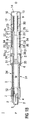
図1は、自動注射器1の異なる断面平面の2つの長手方向の断面を示しており、この異なる断面平面は互いに対して約90°回転されたものであり、この場合自動注射器1は、注射を開始する前の初期状態にある。自動注射器1はシャシ2を備える。中空の注射針4を備えたシリンジ3、たとえばHypakシリンジが、自動注射器1の近位部分内に配置される。自動注射器1またはシリンジ3が組み立てられたとき、保護ニードルシールド5が針4に取り付けられる。ストッパ6が、シリンジ3を遠位に封止し、液体薬剤Mを中空針4を通して移動させるように構成される。シリンジ3は、管状キャリア7内に保持され、その中のその近位端において支持される。キャリア7は、シャシ2内にスライド可能に配置される。
FIG. 1 shows two longitudinal cross-sections of different cross-sectional planes of an auto-
圧縮ばねの形状の駆動ばね8が、キャリア7の遠位端内に配置される。プランジャ9は、駆動ばね8の力をストッパ6に送るように働く。
A
駆動ばね8は、キャリア7の遠位キャリア端面10とプランジャ9上に遠位に配置されたスラスト・カラー11との間に搭載される。
The
巻付きトリガ・スリーブ12が、自動注射器1の遠位端Dを覆って配置され、自動注射器1のほぼ全長にわたって延びる。スラスト・カラー11は、プランジャ9が近位方向Pに並進移動することを防止するようにして、キャリア7内の2つの第1の弾性クリップ15の後方に外方向に保持される。第1の弾性クリップ15は、駆動ばね8の負荷の下、スラスト・カラー11にこれらの弾性クリップを外方向に曲げさせるように遠位に傾斜される。しかし、初期の状態では、第1の弾性クリップ15は、トリガ・スリーブ12内のそれぞれの第1のボス13により、外向きに曲がることが防止される。
A
キャリア7は、キャリア7内のそれぞれの開口17内に係合された、シャシ2上の2つの第2の弾性クリップ16によって自動注射器1の近位端Pの近くでシャシ2にロックされる。初期状態では、第2の弾性クリップ16は、トリガ・スリーブ12内のそれぞれの第2のボス18によって外方向に支持され、それによって第2の弾性クリップ16が外向きに曲がり、キャリア7をシャシ2から係合解除させることを防止する。
The
別の圧縮ばねの形状の制御ばね19が、キャリア7周りに配置され、近位カラー20とトリガ・スリーブ12の内面上のリブ21との間で作用する。近位カラー20は、キャリア7内の第1の凹部23内のピン22に係合され、こうして連帯的な軸方向の並進移動のために近位カラー20をキャリア7に結合させる。トリガ・スリーブ12内の第3のボス24は、ピン22が第1の凹部23から係合解除することを防止するようにして、近位カラー20を外向きに支持するように構成される。したがって、制御ばね19の近位端からの負荷は、初期状態では、キャリア7内まで結合される。
A
トリガ・スリーブ12は、制御ばね19の力に抗してキャリア7に対して近位方向Pに移動することが可能にされる。キャリア7が最初、シャシ2にロックされるとき、トリガ・スリーブ12がシャシ2に対して近位方向Pに並進移動することにより、制御ばね19を圧縮する。シャシ2に対する遠位方向Dのトリガ・スリーブ12の延長は、トリガ・スリーブ12上の第1のショルダ26に近位方向Pに当接するシャシ2上の2つの第3の弾性クリップ25によって規定される。初期状態では、第3の弾性クリップ25は、これらが内方向に曲がることを防止し、第1のショルダ26を超えて前進するようにして、キャリア7上の第4のボス27によって内方向に支持される。
The
自動注射器1の作動の順序は以下の通りである。
The order of operation of the
保護ニードルシールド5が、近位端Pから取り外される。針4はこのとき露出されるが、ユーザを偶発的な針の突き刺しによる負傷から保護するためにシャシ2内で依然として安全な距離だけ後退する。キャリア7は、シリンジ3の指フランジ30を収容するための保持ポケット29を示す。トリガ・スリーブ12は、トリガ・スリーブ12およびキャリア7の相対的回転を制限しながら長手方向の並進移動を可能にするようにして、保持ポケット29を収容するための広くされた部分31を備える。こうして針4の回転が防止される。
The
保護ニードルシールド5の取り外し中にキャリア7にかけられたあらゆる軸方向の負荷は、第2の弾性クリップ16によってシャシ2にロックされたキャリア7によって解消される。保護ニードルシールド5が取り外されているとき、シャシ2にかけられた軸方向負荷は、第3の弾性クリップ25および第1のショルダ26を介してユーザによって保持されるトリガ・スリーブ12によって解消される。保護ニードルシールド5の取り外しは、初期状態において近位端P上に配置されたキャップによって容易にすることができ、このキャップは、保護ニードルシールド5(キャップは図示せず)に係合される。
Any axial load applied to the
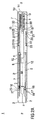
注射を始動させるために、ユーザ、すなわち患者または介護者は、自動注射器1の近位端Pを、注射部位、たとえば患者の皮膚上に置き、トリガ・スリーブ12を注射部位に押し付ける(図2を参照)。シャシ2は、すべての内部部品と共に、トリガ・スリーブ12内へと遠位方向Dに並進移動する。ユーザは、シャシ2のこの並進移動を皮膚接触覆い部の押し下げとして視覚化する。制御ばね19は、この動作を阻むが、そのばね比および予負荷は、これを自然に感じるのに十分なほど低くなるように指定される。この並進移動は完全に可逆的なものであり、すなわち、ユーザは、自動注射器を注射部位に置き、シャシ2(皮膚接触覆い部)を押し下げ、自動注射器1をこれを作動させずに注射部位から取り外すことができ、それによってシャシ2およびトリガ・スリーブ12を制御ばね19の負荷の下、その初期位置に戻すことを可能にする。
To initiate the injection, the user, i.e. patient or caregiver, places the proximal end P of the auto-
自動注射器1は、場合により2段階の薬剤注射機構を有することができる。この場合、図2の位置からのさらなる並進移動は、戻り止め機構(図示せず)によって阻まれる。
The
そのようにする準備ができたとき、ユーザは、トリガ・スリーブ12を保持しながら、自動注射器の近位端Pを注射部位に押し付け続ける。シャシ2は、これにロックされたすべての内部部品と共に、キャリア端面10が自動注射器1の遠位端Dのところでトリガー端面14と接触するまで、トリガ・スリーブ12に対して遠位方向Dに移動する(図3を参照)。
When ready to do so, the user continues to press the proximal end P of the auto-injector against the injection site while holding the
この位置に到達する直前、キャリア7をシャシ2にロックする第2のボス18は、第2の弾性クリップ16がキャリア7との傾斜係合によって外方向に曲がることが可能にされる位置、すなわち近位カラー20を押し付ける制御ばね19によって近位方向Pに偏倚された位置に移動している。シャシ2とキャリア7の間のロックはこうして解放される。制御ばね19は次いで、キャリア7をシリンジ3および針4と共に近位方向Pに強制移動させ、こうして針4を注射部位内に挿入する(図4を参照)。
Immediately before reaching this position, the
図5は、注射深度を規定する最大近位位置に完全に前進されたキャリア7、シリンジ3、および針4を示す。この最大近位位置は、保持ポケット29がシャシ2と接触することによって限定される(図5Aを参照)。最大近位位置に到達する直前、キャリア7、シリンジ3、針4、駆動ばね8およびプランジャ9は、第1のボス13が第1の弾性クリップ15をもはや支持しなくなる遠さまでトリガ・スリーブ12に対して並進移動しており、そのため駆動ばね8の負荷の下、スラスト・カラー11が第1の弾性クリップ15をその傾斜係合によって外に曲げることを可能にし、こうしてプランジャ9を解放する。プランジャ9は、駆動ばね8の負荷の下で近位方向Pに並進移動し始める。駆動ばね8が拡張し、プランジャ9がストッパ6と接触し、薬剤Mが針4から放出される。
FIG. 5 shows the
ストッパ6のこの動作は、ストッパ6がシリンジ3内で最も低い位置になり、それによってシリンジ3を空にするまで続く。ユーザは、これが達成されることを確実にするために、短い時間、たとえば10秒の間注射部位に圧力をかけ続けることが求められる(図6を参照)。
This movement of the
ユーザが自動注射器1を注射部位から引っ込めるとき、シャシ2は、すべての内部構成要素と共に、トリガ・スリーブ12上のリブ21とキャリア7にロックされた近位カラー20との間で作用する制御ばね19によって、トリガ・スリーブ12から外に近位方向Dに延びる。第2の弾性クリップ16は、トリガ・スリーブ12が注射部位からの取り外し時に遠位方向Dに移動するとき、その元の径方向位置に戻り、第2のボス18がこのクリップを超えて戻るように進むことを可能にする。針4は、この動作中注射部位から引っ込められておらず、その理由は、これにより、自動注射器1が、薬剤Mの送達中、注射部位に対するトリガ・スリーブ12の動作に影響されやすくなるためである。
When the user retracts the auto-
シャシ2が図1のような初期の注射前位置まで延びるとき、近位カラー20をキャリア7にロックするトリガ・スリーブ12上の第3のボス24は、遠位方向Dに移動して外れており、こうしてピン22が、制御ばね19の負荷の下、傾斜係合によって第1の凹部23から係合解除することを可能にする(図7を参照)。近位カラー20は、こうしてキャリア7から解放される。制御ばね19の近位端上の負荷は、このときシャシ2にかけられる。
When the
シャシ2が近位方向Pに移動し続けると、これは、その初期の注射前位置に到達するが、キャリア7上の第4のボス27は針挿入中に移動して外れているため、停止部はもはや能動的ではない。その代わり、第3の弾性クリップ25が、第1のショルダ26との傾斜係合によってキャリア7内の第2の凹部28内に内方向に曲げられる。シャシ2がトリガ・スリーブ12に対して近位方向Pに並進移動し続けると、第3の弾性クリップ25は、第1のショルダ26の後方で再度外方向に曲がる。シャシ2は、引き続きトリガ・スリーブ12の近位端から外に延びる。
As the
シャシ2がその初期の注射前位置を超えて突起するとき、これは、キャリア7および針4の近位方向Pのさらなる並進移動をもはや制限することはできない。その代わり、キャリア・サブアセンブリのさらなる実質的な並進移動は、制御ばね19の遠位端がキャリア7上のフランジ32と接触することによって制限される。制御ばね19の遠位端は、このときトリガ・スリーブ12およびキャリア7の両方に負荷をかける。これは、キャリア7およびシリンジ3を自動注射器1内で図8のような位置に保持する。図示する実施形態では、慣性負荷の下でキャリア7が再び出現することを防止する追加のロック部は存在しない。シリンジ3が自動注射器1内で制止されることを確実にするために、トリガ・スリーブ12、シャシ2、およびキャリア7の間にスナップ特徴を備えたロック部を導入することが可能である。
When the
ユーザが、シリンジが完全に空になる前に注射部位から自動注射器1を取り外そうとした場合でも、シャシ2の説明された動作が達成される。しかし、この場合、シリンジ3は、注射部位からの取り外し後に完全に空にされる。
The described operation of the
制御ばね19は、キャリア7/トリガ・スリーブ12とシャシ2の間で働くことで、引き続きシャシ2を自動注射器1の近位端Pから外に押し出す。自動注射器1はこのとき初期状態より長くなる。
The
観察ウィンドウが、シリンジ内容物を観察するためにシャシ2およびキャリア7内にトリガ・スリーブ12内の開口形状で配置されてよい。
An observation window may be arranged in the form of an opening in the
1 自動注射器
2 シャシ
3 シリンジ
4 中空の注射針
5 保護ニードルシールド
6 ストッパ
7 キャリア
8 駆動ばね
9 プランジャ
10 遠位キャリア端面
11 スラスト・カラー
12 トリガ・スリーブ
13 第1のボス
14 トリガー端面
15 第1の弾性クリップ
16 第2の弾性クリップ
17 開口
18 第2のボス
19 制御ばね
20 近位カラー
21 リブ
22 ピン
23 第1の凹部
24 第3のボス
25 第3の弾性クリップ
26 第1のショルダ
27 第4のボス
28 第2の凹部
29 保持ポケット
30 指フランジ
31 広くされた部分
32 フランジ
D 遠位端、遠位方向
M 薬剤
P 近位端、近位方向
DESCRIPTION OF
Claims (14)
−中空針(4)、およびシリンジ(3)を封止し薬剤(M)を変位させるためのストッパ(6)を備えたシリンジ(3)とを含むように配置され、遠位端(D)、および注射部位に対して当てる予定のオリフィスを備えた近位端(P)とを有する管状シャシ(2)(シリンジ(3)はシャシ(2)に対してスライド可能に配置される)と、
−シリンジ(3)を操作して薬剤(M)の用量を供給することができる駆動ばね(8)と、
−針挿入のために、針(4)をシャシ(2)内側の覆われた位置から、オリフィスを通り近位端(P)を過ぎて前進位置に押すこと、および
−薬剤(M)を、少なくとも部分的に送達した後シャシ(2)を針(4)上に前進させることが可能である、制御ばね(19)と、
−手動作動前駆動ばね(8)および制御ばね(19)を加圧状態でロックするように配置され、手動操作の際、注射のために制御ばね(19)および/または駆動ばね(8)を解放することができる起動手段と、
を含み、
ここで、管状キャリア(7)を含むキャリア・サブアセンブリが、シャシ内にスライド可能に配置され、キャリア(7)は、シリンジ(3)と、駆動ばね(8)と、駆動ばね(8)の負荷をストッパ(6)に送るためのプランジャ(9)とを含み、シリンジ(3)は、ジョイント軸方向並進運動のためキャリア(7)にロックされ、制御ばね(19)は、針挿入のため第1の連動手段(20、23、24)によってキャリア(7)に連結可能であり、起動手段は、キャリアが少なくともほぼ注射深度に到達したとき、駆動ばね(8)を解放するように配置された第2の連動手段(11、13、15)を含み、第1の連動手段(20、23、24)は、制御ばね(8)をキャリア(7)からデカップルし、これを針(4)上の針の安全位置へと前進させるためにこれをシャシ(2)にカップリングするように配置される、上記自動注射器(1)。 An automatic syringe (1) for administering a dose of liquid medicament (M) comprising:
A hollow needle (4) and a syringe (3) with a stopper (6) for sealing the syringe (3) and displacing the drug (M), the distal end (D) And a tubular chassis (2) having a proximal end (P) with an orifice intended to impinge against the injection site (syringe (3) is slidably disposed relative to the chassis (2));
A drive spring (8) capable of operating the syringe (3) to supply a dose of drug (M);
For needle insertion, pushing the needle (4) from the covered position inside the chassis (2), through the orifice and past the proximal end (P) to the advanced position; and A control spring (19) capable of advancing the chassis (2) onto the needle (4) after at least partial delivery;
The pre-manual actuation drive spring (8) and the control spring (19) are arranged to lock in a pressurized state, and during manual operation, the control spring (19) and / or the drive spring (8) are inserted for injection. Activation means that can be released; and
Including
Here, a carrier subassembly including a tubular carrier (7) is slidably disposed within the chassis, and the carrier (7) comprises a syringe (3), a drive spring (8), and a drive spring (8). A plunger (9) for delivering a load to the stopper (6), the syringe (3) is locked to the carrier (7) for joint axial translation and the control spring (19) is for needle insertion Connectable to the carrier (7) by the first interlocking means (20, 23, 24), the activation means is arranged to release the drive spring (8) when the carrier has reached at least about the injection depth. Second interlocking means (11, 13, 15), the first interlocking means (20, 23, 24) decouples the control spring (8) from the carrier (7) and connects it to the needle (4) To the safe position of the upper needle This in order to advance the is arranged to the coupling to the chassis (2), the automatic injector (1).
ぼ全長にわたって延び、トリガ・スリーブ(12)は、シャシ(2)に対する近位方向(P)への並進運動の際に制御ばね(19)を解放するように配置されることを特徴とする、請求項1に記載の自動注射器(1)。 The activation means includes a wound trigger sleeve (12) disposed over the distal end (D) of the auto-injector (1), the trigger sleeve (12) extending over at least approximately the entire length of the auto-injector (1). The trigger sleeve (12) is arranged to release the control spring (19) upon translational movement in the proximal direction (P) relative to the chassis (2). Automatic syringe (1) as described.
してシャシ(2)が初期の注射前位置を超えて針安全位置へと走行することを可能にすることを特徴とする、請求項5〜7のいずれか一項に記載の自動注射器(1)。 At least one third resilience arranged such that the fourth interlocking means (25, 26, 27) abuts in the proximal direction (P) against the shoulder (26) in the trigger sleeve (12). A clip (25) is provided on the chassis (2) and a fourth boss (27) supports the third elastic clip (25) on the inside and prevents the carrier (7) from bending inside. The fourth boss (27), arranged above, is in translational movement in the proximal direction (P) relative to the chassis (2) of the carrier subassembly during needle insertion from behind the third elastic clip (25). Arranged to be removed, thereby allowing the third elastic clip (25) to bend inward by tilting engagement with the fourth boss (27) under the load of the control spring (19). , Thus the chassis (2) is the initial injection Located beyond the, characterized in that it possible to travel to the needle safety position, automatic injector according to any one of claims 5-7 (1).
−第1の連動手段(20、23、24)によって制御ばね(19)をキャリア(7)にカップリングさせ、初期状態で第2の連動手段(11、13、15)によって駆動ばね(8)の解放を防止する工程と、
−自動注射器(1)の近位端(P)が注射部位に押し付けられているとき制御ばね(19)の力に抗して、シャシ(2)に対して近位方向(P)にトリガ・スリーブ(12)を並進移動させる工程と、
−トリガ・スリーブ(12)が完全に並進移動した際、シリンジ(3)上の中空注射針(4)を注射部位に挿入するためにキャリア・サブアセンブリを前進させる工程と、
−針挿入中、針(4)が少なくともほぼ注射深度まで到達したとき第2の連動手段(11、13、15)によって駆動ばね(8)を解放し、それによって駆動ばね(8)が、薬剤(M)を少なくとも部分的に送達するようにプランジャ(9)およびストッパ(6)を前進させることを可能にする工程と、
−自動注射器(1)の注射部位からの取り外しで、トリガ・スリーブ(12)をキャリア・サブアセンブリに対して制御ばね(19)の負荷の下で遠位方向(D)に並進移動させ、それによって第1の連動手段(20、23、24)によって制御ばね(19)をシャシ(2)に連結する工程と、
−制御ばね(19)の負荷の下、シャシ(2)をキャリア・サブアセンブリに対して近位方向(P)に針安全位置へと前進させる工程と、
を含む、上記方法。 A tubular chassis (2) and a carrier subassembly including a tubular carrier (7) slidably disposed within the chassis (2), the carrier (7) comprising a syringe (3) and a drive spring (8 ) And a plunger (9) for sending the load of the drive spring (8) to the stopper (6) of the syringe (3), where the syringe (3) is a carrier (7 ) And a control spring (19) is disposed around the carrier (7) over the distal end (D) of the auto-injector (1) and extends over at least approximately the entire length of the auto-injector (1). Arranged inside the sleeve (12), the first interlocking means (20, 23, 24) are arranged on the control spring (19) according to the relative axial position of the carrier (7) and the trigger sleeve (12). Proximal end Arranged to connect to the carrier (7) or chassis (2), the distal end of the control spring (19) is connected to the trigger sleeve (12) and the second interlocking means (11, 13, 15) Depending on the relative axial position of the trigger sleeve (12) and the carrier (7), the automatic injector (1) arranged to prevent or enable the release of the drive spring (8) A method for operating,
The control spring (19) is coupled to the carrier (7) by the first interlocking means (20, 23, 24) and in the initial state the drive spring (8) by the second interlocking means (11, 13, 15) The process of preventing the release of
Triggering in the proximal direction (P) relative to the chassis (2) against the force of the control spring (19) when the proximal end (P) of the auto-injector (1) is pressed against the injection site; Translating the sleeve (12);
Advancing the carrier subassembly to insert the hollow injection needle (4) on the syringe (3) into the injection site when the trigger sleeve (12) is fully translated;
-During needle insertion, when the needle (4) reaches at least approximately the injection depth, the drive spring (8) is released by the second interlocking means (11, 13, 15), whereby the drive spring (8) Allowing advancement of the plunger (9) and the stopper (6) to at least partially deliver (M);
-Removal of the automatic injector (1) from the injection site translates the trigger sleeve (12) in the distal direction (D) under the load of the control spring (19) relative to the carrier subassembly; Connecting the control spring (19) to the chassis (2) by the first interlocking means (20, 23, 24) by:
Advancing the chassis (2) under the load of the control spring (19) in the proximal direction (P) relative to the carrier subassembly to the needle safety position;
Including the above method.
Applications Claiming Priority (7)
| Application Number | Priority Date | Filing Date | Title |
|---|---|---|---|
| EP10186999.8 | 2010-10-08 | ||
| EP10186999A EP2438943A1 (en) | 2010-10-08 | 2010-10-08 | Auto-injector |
| US201161432693P | 2011-01-14 | 2011-01-14 | |
| US61/432,693 | 2011-01-14 | ||
| EP11151210.9 | 2011-01-18 | ||
| EP11151210A EP2476449A1 (en) | 2011-01-18 | 2011-01-18 | Auto-injector |
| PCT/EP2011/067496 WO2012045833A1 (en) | 2010-10-08 | 2011-10-06 | Auto-injector |
Publications (3)
| Publication Number | Publication Date |
|---|---|
| JP2013539682A JP2013539682A (en) | 2013-10-28 |
| JP2013539682A5 JP2013539682A5 (en) | 2014-11-06 |
| JP5940545B2 true JP5940545B2 (en) | 2016-06-29 |
Family
ID=45927244
Family Applications (1)
| Application Number | Title | Priority Date | Filing Date |
|---|---|---|---|
| JP2013532205A Active JP5940545B2 (en) | 2010-10-08 | 2011-10-06 | Automatic syringe |
Country Status (19)
| Country | Link |
|---|---|
| US (1) | US9421337B2 (en) |
| EP (2) | EP3366336B1 (en) |
| JP (1) | JP5940545B2 (en) |
| KR (1) | KR20130138797A (en) |
| CN (1) | CN103249442B (en) |
| AR (1) | AR083346A1 (en) |
| AU (1) | AU2011311560B2 (en) |
| BR (1) | BR112013008401A2 (en) |
| CA (1) | CA2813524A1 (en) |
| DK (1) | DK2624885T3 (en) |
| IL (1) | IL225429A (en) |
| MX (1) | MX342555B (en) |
| MY (1) | MY159004A (en) |
| NZ (1) | NZ609117A (en) |
| RU (1) | RU2585693C2 (en) |
| SG (1) | SG189082A1 (en) |
| TW (1) | TWI541039B (en) |
| WO (1) | WO2012045833A1 (en) |
| ZA (1) | ZA201302364B (en) |
Families Citing this family (45)
| Publication number | Priority date | Publication date | Assignee | Title |
|---|---|---|---|---|
| WO2009044401A2 (en) | 2007-10-02 | 2009-04-09 | Yossi Gross | External drug pump |
| GB201020475D0 (en) | 2010-12-02 | 2011-01-19 | Oval Medical Technologies Ltd | Delivery mechanism for an autoinjector |
| EP2489385A1 (en) | 2011-02-18 | 2012-08-22 | Sanofi-Aventis Deutschland GmbH | Auto-injector |
| EP2489386A1 (en) | 2011-02-18 | 2012-08-22 | Sanofi-Aventis Deutschland GmbH | Auto-injector |
| EP2489382A1 (en) * | 2011-02-18 | 2012-08-22 | Sanofi-Aventis Deutschland GmbH | Auto-injector |
| EP2662104A1 (en) * | 2012-05-07 | 2013-11-13 | Sanofi-Aventis Deutschland GmbH | Detent mechanism for a medicament delivery device |
| FR2990867B1 (en) * | 2012-05-25 | 2015-04-24 | Valois Sas | autoinjector |
| US9717851B2 (en) | 2012-05-25 | 2017-08-01 | Aptar France Sas | Autoinjector |
| US9707343B2 (en) | 2012-05-25 | 2017-07-18 | Aptar France Sas | Autoinjector comprising a time delay device having a planetary gear set for delaying the retraction of the needle |
| FR2990862B1 (en) * | 2012-05-25 | 2015-05-15 | Valois Sas | autoinjector |
| EP2854899B1 (en) | 2012-05-25 | 2017-07-12 | Aptar France SAS | Autoinjector |
| WO2013175142A1 (en) | 2012-05-25 | 2013-11-28 | Aptar France Sas | Autoinjector |
| WO2014049214A1 (en) | 2012-09-27 | 2014-04-03 | Aptar France Sas | Autoinjector |
| WO2014195183A1 (en) * | 2013-06-03 | 2014-12-11 | Novo Nordisk A/S | Medical injection device |
| FR3013601B1 (en) | 2013-11-25 | 2017-08-11 | Aptar France Sas | Autoinjector. |
| US9415176B1 (en) | 2015-01-22 | 2016-08-16 | West Pharmaceutical Services, Inc. | Autoinjector having an end-of-dose visual indicator |
| ES2905870T3 (en) | 2015-02-27 | 2022-04-12 | Amgen Inc | Drug delivery device having a needle guard mechanism with an adjustable threshold resistance to movement of the needle guard |
| US20200384209A1 (en) * | 2015-04-24 | 2020-12-10 | Shl Medical Ag | Drive mechanism |
| WO2016169719A1 (en) * | 2015-04-24 | 2016-10-27 | Carebay Europe Ltd | Drive mechanism |
| AU2016314036A1 (en) * | 2015-08-31 | 2018-02-01 | 4C Design Limited | An injector |
| FR3041262B1 (en) | 2015-09-22 | 2020-11-20 | Aptar France Sas | AUTOINJECTOR |
| US10576207B2 (en) | 2015-10-09 | 2020-03-03 | West Pharma. Services IL, Ltd. | Angled syringe patch injector |
| CN113648488B (en) | 2015-10-09 | 2024-03-29 | 西医药服务以色列分公司 | Curved fluid path attachment to prefilled fluid reservoir |
| WO2017127215A1 (en) | 2016-01-21 | 2017-07-27 | Medimop Medical Projects Ltd. | Needle insertion and retraction mechanism |
| CN113041432B (en) | 2016-01-21 | 2023-04-07 | 西医药服务以色列有限公司 | Medicament delivery device comprising a visual indicator |
| CN111544704B (en) | 2016-01-21 | 2022-06-03 | 西医药服务以色列有限公司 | Force containment in autoinjectors |
| US11389597B2 (en) | 2016-03-16 | 2022-07-19 | West Pharma. Services IL, Ltd. | Staged telescopic screw assembly having different visual indicators |
| GB201607491D0 (en) * | 2016-04-29 | 2016-06-15 | Owen Mumford Ltd | Injection devices |
| US11338090B2 (en) | 2016-08-01 | 2022-05-24 | West Pharma. Services IL, Ltd. | Anti-rotation cartridge pin |
| RU174870U1 (en) * | 2016-09-02 | 2017-11-08 | Общество с ограниченной ответственностью "МЕДИКАЛ ИНЖИНИРИНГ" | DEVICE FOR INJECTION OF MEDICINES |
| JP6856840B2 (en) | 2016-12-27 | 2021-04-14 | アクション メディカル テクノロジーズ,エルエルシーAction Medical Technologies,Llc | Injector and how to operate the injector |
| CN114191659B (en) * | 2017-03-15 | 2023-07-11 | 欧文蒙福德有限公司 | Injection device |
| CN110446512B (en) * | 2017-03-28 | 2022-03-18 | 美国安进公司 | Plunger rod and syringe assembly systems and methods |
| TWI630938B (en) * | 2017-04-25 | 2018-08-01 | 群康生技股份有限公司 | Injection pen |
| CN110869072B (en) | 2017-05-30 | 2021-12-10 | 西部制药服务有限公司(以色列) | Modular drive mechanism for a wearable injector |
| CN107468289A (en) * | 2017-08-03 | 2017-12-15 | 宋瑞昕 | Imbedding tool |
| EP3801694A4 (en) | 2018-06-08 | 2022-03-16 | Antares Pharma, Inc. | Auto-insert injector |
| US11224696B2 (en) | 2018-07-10 | 2022-01-18 | Action Medical Technologies, Llc | Apparatuses and method for injecting medicaments |
| US10980950B2 (en) * | 2018-10-25 | 2021-04-20 | Sharps Technology Inc. | Ultra-low waste needle and syringe system that automatically and passively renders a needle safe during the injection process |
| USD893712S1 (en) | 2019-02-15 | 2020-08-18 | Action Medical Technologies, Llc | Grip for autoinjectors |
| GB2593137B (en) * | 2019-12-20 | 2022-06-01 | Owen Mumford Ltd | Syringe apparatus |
| JP7323240B2 (en) | 2020-03-25 | 2023-08-08 | アクション メディカル テクノロジーズ,エルエルシー | Apparatus and method for infusing drugs |
| US20230166039A1 (en) * | 2020-04-14 | 2023-06-01 | West Pharmaceutical Services, Inc. | Injection device with disengagement feature and method for disengaging a plunger from a power source |
| US11759576B2 (en) | 2020-06-05 | 2023-09-19 | Action Medical Technologies, Llc | Parenteral injection apparatus |
| EP4039294A1 (en) | 2021-02-05 | 2022-08-10 | Ruslan Ravilievich Muratov | Autoinjector |
Family Cites Families (9)
| Publication number | Priority date | Publication date | Assignee | Title |
|---|---|---|---|---|
| US6663602B2 (en) * | 2000-06-16 | 2003-12-16 | Novo Nordisk A/S | Injection device |
| AU2001281753A1 (en) | 2000-08-29 | 2002-03-13 | Novo-Nordisk A/S | Automatic injection device with torsion function for retraction of needle |
| DE10342058B4 (en) * | 2003-09-11 | 2007-10-25 | Tecpharma Licensing Ag | Administration device for an injectable product with a trigger safety device |
| EP1703929B1 (en) * | 2003-12-18 | 2009-10-21 | Tecpharma Licensing AG | Releasable injection device |
| ATE432101T1 (en) * | 2005-07-15 | 2009-06-15 | Shl Group Ab | INJECTOR WITH AUTOMATIC NEEDLE INJECTION, INJECTION AND NEEDLE RETRACTION |
| GB0601309D0 (en) * | 2006-01-23 | 2006-03-01 | Medical House The Plc | Injection device |
| EP2219710B2 (en) * | 2007-11-12 | 2020-08-05 | Medicom Innovation Partner a/s | Auto injector with automatic needle retraction |
| EP3017837B1 (en) * | 2008-10-29 | 2017-02-01 | SHL Group AB | Injection device |
| EP2438942A1 (en) | 2010-10-08 | 2012-04-11 | Sanofi-Aventis Deutschland GmbH | Auto-injector |
-
2011
- 2011-10-06 MY MYPI2013001016A patent/MY159004A/en unknown
- 2011-10-06 MX MX2013003754A patent/MX342555B/en active IP Right Grant
- 2011-10-06 US US13/877,493 patent/US9421337B2/en active Active
- 2011-10-06 JP JP2013532205A patent/JP5940545B2/en active Active
- 2011-10-06 DK DK11764584.6T patent/DK2624885T3/en active
- 2011-10-06 BR BR112013008401A patent/BR112013008401A2/en not_active IP Right Cessation
- 2011-10-06 TW TW100136198A patent/TWI541039B/en not_active IP Right Cessation
- 2011-10-06 CA CA2813524A patent/CA2813524A1/en not_active Abandoned
- 2011-10-06 AR ARP110103710A patent/AR083346A1/en not_active Application Discontinuation
- 2011-10-06 NZ NZ609117A patent/NZ609117A/en not_active IP Right Cessation
- 2011-10-06 EP EP18160286.3A patent/EP3366336B1/en active Active
- 2011-10-06 RU RU2013120960/14A patent/RU2585693C2/en not_active IP Right Cessation
- 2011-10-06 AU AU2011311560A patent/AU2011311560B2/en not_active Ceased
- 2011-10-06 EP EP11764584.6A patent/EP2624885B1/en active Active
- 2011-10-06 KR KR1020137011519A patent/KR20130138797A/en not_active Application Discontinuation
- 2011-10-06 WO PCT/EP2011/067496 patent/WO2012045833A1/en active Application Filing
- 2011-10-06 CN CN201180058932.6A patent/CN103249442B/en active Active
- 2011-10-06 SG SG2013022025A patent/SG189082A1/en unknown
-
2013
- 2013-03-21 IL IL225429A patent/IL225429A/en active IP Right Grant
- 2013-04-02 ZA ZA2013/02364A patent/ZA201302364B/en unknown
Also Published As
| Publication number | Publication date |
|---|---|
| TW201221171A (en) | 2012-06-01 |
| KR20130138797A (en) | 2013-12-19 |
| RU2013120960A (en) | 2014-11-20 |
| MY159004A (en) | 2016-11-30 |
| CA2813524A1 (en) | 2012-04-12 |
| CN103249442B (en) | 2015-08-05 |
| DK2624885T3 (en) | 2018-06-14 |
| IL225429A (en) | 2016-09-29 |
| JP2013539682A (en) | 2013-10-28 |
| EP3366336B1 (en) | 2024-04-10 |
| CN103249442A (en) | 2013-08-14 |
| RU2585693C2 (en) | 2016-06-10 |
| US9421337B2 (en) | 2016-08-23 |
| TWI541039B (en) | 2016-07-11 |
| US20130190722A1 (en) | 2013-07-25 |
| MX2013003754A (en) | 2013-12-16 |
| NZ609117A (en) | 2014-12-24 |
| AR083346A1 (en) | 2013-02-21 |
| SG189082A1 (en) | 2013-05-31 |
| MX342555B (en) | 2016-10-05 |
| EP2624885B1 (en) | 2018-03-07 |
| AU2011311560B2 (en) | 2014-12-11 |
| EP2624885A1 (en) | 2013-08-14 |
| ZA201302364B (en) | 2013-12-23 |
| BR112013008401A2 (en) | 2016-06-21 |
| WO2012045833A1 (en) | 2012-04-12 |
| AU2011311560A1 (en) | 2013-04-18 |
| EP3366336A1 (en) | 2018-08-29 |
| IL225429A0 (en) | 2013-06-27 |
Similar Documents
| Publication | Publication Date | Title |
|---|---|---|
| JP5940545B2 (en) | Automatic syringe | |
| US11458252B2 (en) | Auto-injector | |
| EP2654831B1 (en) | Auto-injector | |
| US9283327B2 (en) | Auto-injector | |
| EP2438943A1 (en) | Auto-injector | |
| EP2476449A1 (en) | Auto-injector |
Legal Events
| Date | Code | Title | Description |
|---|---|---|---|
| A521 | Request for written amendment filed |
Free format text: JAPANESE INTERMEDIATE CODE: A523 Effective date: 20140919 |
|
| A621 | Written request for application examination |
Free format text: JAPANESE INTERMEDIATE CODE: A621 Effective date: 20140919 |
|
| A977 | Report on retrieval |
Free format text: JAPANESE INTERMEDIATE CODE: A971007 Effective date: 20150729 |
|
| A131 | Notification of reasons for refusal |
Free format text: JAPANESE INTERMEDIATE CODE: A131 Effective date: 20150811 |
|
| A521 | Request for written amendment filed |
Free format text: JAPANESE INTERMEDIATE CODE: A523 Effective date: 20151110 |
|
| TRDD | Decision of grant or rejection written | ||
| A01 | Written decision to grant a patent or to grant a registration (utility model) |
Free format text: JAPANESE INTERMEDIATE CODE: A01 Effective date: 20160426 |
|
| A61 | First payment of annual fees (during grant procedure) |
Free format text: JAPANESE INTERMEDIATE CODE: A61 Effective date: 20160518 |
|
| R150 | Certificate of patent or registration of utility model |
Ref document number: 5940545 Country of ref document: JP Free format text: JAPANESE INTERMEDIATE CODE: R150 |
|
| R250 | Receipt of annual fees |
Free format text: JAPANESE INTERMEDIATE CODE: R250 |
|
| R250 | Receipt of annual fees |
Free format text: JAPANESE INTERMEDIATE CODE: R250 |
|
| R250 | Receipt of annual fees |
Free format text: JAPANESE INTERMEDIATE CODE: R250 |
|
| R250 | Receipt of annual fees |
Free format text: JAPANESE INTERMEDIATE CODE: R250 |
|
| R250 | Receipt of annual fees |
Free format text: JAPANESE INTERMEDIATE CODE: R250 |