JP5937563B2 - Communication base station and control method thereof - Google Patents
Communication base station and control method thereof Download PDFInfo
- Publication number
- JP5937563B2 JP5937563B2 JP2013226219A JP2013226219A JP5937563B2 JP 5937563 B2 JP5937563 B2 JP 5937563B2 JP 2013226219 A JP2013226219 A JP 2013226219A JP 2013226219 A JP2013226219 A JP 2013226219A JP 5937563 B2 JP5937563 B2 JP 5937563B2
- Authority
- JP
- Japan
- Prior art keywords
- communication
- network
- address
- base station
- terminal
- Prior art date
- Legal status (The legal status is an assumption and is not a legal conclusion. Google has not performed a legal analysis and makes no representation as to the accuracy of the status listed.)
- Active
Links
- 238000004891 communication Methods 0.000 title claims description 214
- 238000000034 method Methods 0.000 title claims description 12
- 230000004044 response Effects 0.000 claims description 14
- 238000004590 computer program Methods 0.000 claims description 4
- 238000002955 isolation Methods 0.000 claims 1
- 238000010586 diagram Methods 0.000 description 18
- 238000012545 processing Methods 0.000 description 14
- 230000007246 mechanism Effects 0.000 description 5
- 238000011161 development Methods 0.000 description 4
- 230000000694 effects Effects 0.000 description 4
- 238000005516 engineering process Methods 0.000 description 3
- 230000008520 organization Effects 0.000 description 3
- 230000008859 change Effects 0.000 description 2
- 230000008569 process Effects 0.000 description 2
- 230000002730 additional effect Effects 0.000 description 1
- 230000005540 biological transmission Effects 0.000 description 1
- 230000002860 competitive effect Effects 0.000 description 1
- 238000002474 experimental method Methods 0.000 description 1
- 238000012827 research and development Methods 0.000 description 1
- 238000000926 separation method Methods 0.000 description 1
- 238000000060 site-specific infrared dichroism spectroscopy Methods 0.000 description 1
- 230000003068 static effect Effects 0.000 description 1
- 230000005641 tunneling Effects 0.000 description 1
Images


Description
本発明は、通信技術に関する。より詳しくは、本発明は、ノートPCやスマートホンなどの通信端末をネットワークに接続するための通信基地局に関する。 The present invention relates to communication technology. More specifically, the present invention relates to a communication base station for connecting a communication terminal such as a notebook PC or smart phone to a network.
以下では無線通信を例に用いて説明を行う。しかし、本発明は、有線通信であるか無線通信であるかを問わずに適用可能である。 Hereinafter, description will be made using wireless communication as an example. However, the present invention can be applied regardless of whether it is wired communication or wireless communication.
近年、WiFiなどの無線通信を介してネットワークに接続し、リモートオフィスなどにアクセスする機会が増えている。しかし、ネットワークを介した不正アクセスが横行し、より安全な通信手段の実現が必要とされている。 In recent years, an opportunity to connect to a network via wireless communication such as WiFi and access a remote office or the like is increasing. However, unauthorized access via the network is rampant, and it is necessary to realize safer communication means.
従来の無線通信では、1つの無線基地局(アクセスポイント)に接続される複数の無線端末は、同一のIPアドレスレンジを用いることが一般的である。その結果として、これら複数の無線端末間の通信はIPレイヤで接続され、IPレイヤで個々の無線端末を隔離できない。また、1つのアクセスポイントにおいて、複数の論理アクセスポイント識別子であるサービスセット識別子(SSID)を利用した場合であっても、一つのSSIDに接続する複数の無線端末間では、同一のIPアドレスやIPアドレスレンジが割り振られるため、やはり、IPレイヤで個々の無線端末を隔離することができない。 In conventional wireless communication, a plurality of wireless terminals connected to one wireless base station (access point) generally use the same IP address range. As a result, communication between the plurality of wireless terminals is connected at the IP layer, and individual wireless terminals cannot be isolated at the IP layer. Further, even if a single access point uses service set identifiers (SSIDs) that are a plurality of logical access point identifiers, the same IP address or IP address is used between a plurality of wireless terminals connected to one SSID. Again, because the address range is allocated, individual wireless terminals cannot be isolated at the IP layer.
その結果、これら複数の無線端末は、論理的に分離されていないネットワークを介して通信を行うことになる。例えば、転送されるパケットの識別子を用いて、仮想回線相互間が分離されているだけである。このように、従来の無線通信では、同一の無線基地局を介して通信をする複数の無線端末間の通信を分離する仕組みは存在していない。また、無線基地局で利用できるIPアドレス数や、IPアドレスレンジを容易に増やせる仕組みは存在しない。このような技術的な状況が、無線通信の安全性に問題が生じる原因となっている。 As a result, the plurality of wireless terminals communicate via a network that is not logically separated. For example, the virtual lines are only separated from each other using the identifier of the transferred packet. As described above, in conventional wireless communication, there is no mechanism for separating communication between a plurality of wireless terminals that perform communication through the same wireless base station. Also, there is no mechanism that can easily increase the number of IP addresses that can be used in a radio base station or the IP address range. Such a technical situation causes a problem in the safety of wireless communication.
本発明と関連する可能性がある先行技術文献をサーチしたところ、下記の3つの特許文献が発見された。しかし、特許文献1は、端末固有の識別子ではなく、呼の識別子を利用しているところが本発明とは異なる。また、特許文献1記載の発明は、IPアドレスや、IPアドレスレンジを払い出す仕組みを持っていない。また、特許文献2は、リング構成のネットワークに複数の無線基地局が接続され、その無線基地局間でATMなどを利用した論理回線(仮想回線)を構築する方法であり、本発明とは異なる。更に、特許文献3は、無線端末から仮想回線識別を受信し、OAMセルを利用して仮想回線を管理する仕組みであり、本発明とは異なっている。 When searching for prior art documents that may be related to the present invention, the following three patent documents were found. However, Patent Document 1 differs from the present invention in that a call identifier is used instead of a terminal-specific identifier. Further, the invention described in Patent Document 1 does not have a mechanism for paying out an IP address or an IP address range. Patent Document 2 is a method in which a plurality of radio base stations are connected to a network having a ring configuration, and a logical line (virtual line) using ATM or the like is constructed between the radio base stations, which is different from the present invention. . Furthermore, Patent Document 3 is a mechanism for receiving a virtual circuit identification from a wireless terminal and managing the virtual circuit using an OAM cell, which is different from the present invention.
また、公刊された文献ではないが、<http://www.connect802.com/download/aruba/AP-2E.pdf>では、米国アルバネットワークス社(Aruba Networks)から市販されている製品に関する説明がなされている。この文書には、全ての無線基地局から一元的にIPレベルのGREトンネルを利用して管理サーバ(コントローラ)にトンネルを構築する技術が記載されている。しかし、アルバネットワークス社のこの製品は、個々の無線端末毎に仮想回線を作る事はできない点で、本発明とは異なっている。 In addition, although not published, <http://www.connect802.com/download/aruba/AP-2E.pdf> describes products available from Aruba Networks in the United States. Has been made. This document describes a technique for constructing a tunnel in a management server (controller) using an IP level GRE tunnel from all wireless base stations in a centralized manner. However, this product of Aruba Networks is different from the present invention in that a virtual circuit cannot be created for each wireless terminal.
本発明は、上述した従来の無線通信における問題点を解決するために、APに接続する複数の無線端末がそれぞれ論理的に閉じた閉域ネットワークを構成できることを可能にすることによって、無線通信の安全性を向上させることを目的とする。 In order to solve the above-described problems in the conventional wireless communication, the present invention makes it possible to configure a closed network in which a plurality of wireless terminals connected to an AP can be logically closed, thereby ensuring the safety of wireless communication. The purpose is to improve the performance.
本発明によると、複数の通信端末がネットワークに接続する際にネットワークへのアクセスポイントとして機能する通信基地局であって、複数の通信端末のそれぞれを物理的に識別する物理アドレスに対応するネットワークアドレスが記憶されているデータベースと、複数の通信端末から受信された通信リクエストに応答して、通信リクエストに含まれているそれぞれの通信端末の物理アドレスに対応するネットワークアドレスをデータベースから取得し、取得されたネットワークアドレスを用いて複数の通信端末のそれぞれからネットワークを介する論理的に隔離された複数の通信回線を形成する通信制御手段と、を備えている通信基地局が提供される。 According to the present invention, when a plurality of communication terminals are connected to a network, the communication base station functions as an access point to the network, and a network address corresponding to a physical address that physically identifies each of the plurality of communication terminals. In response to communication requests received from multiple communication terminals and the network addresses corresponding to the physical addresses of the respective communication terminals included in the communication request. There is provided a communication base station comprising communication control means for forming a plurality of logically isolated communication lines through a network from each of a plurality of communication terminals using the network address .
このような通信制御手段において、ネットワーク経路制御や通信回線の帯域制御の機能をネットワークスイッチなどのネットワーク装置から分離して、サーバなどのコントローラで一元管理する仕組みであるSDN(Software Defined Network)と称される技術が存在する。本発明でも、このSDNの技術を利用することが可能である。 In such communication control means, the network path control and communication line bandwidth control functions are separated from network devices such as network switches, and are called SDN (Software Defined Network), which is a centralized management system using a controller such as a server. There are technologies that can be used. In the present invention, this SDN technology can also be used.
また、本発明によると、上述した通信制御手段が、複数の通信端末のそれぞれに異なるIPアドレスまたはIPレンジを割り当てる手段を更に備えていることを特徴とする通信基地局が提供される。 According to the present invention, there is provided a communication base station characterized in that the communication control means described above further comprises means for assigning different IP addresses or IP ranges to a plurality of communication terminals.
更にまた、本発明によると、ネットワーク上に形成される複数の論理的通信回線をVXLANなどのレイヤ3で構成することにより、インターネットなどの広域IPネットワーク上に複数の論理的通信回線を形成する手段を更に備えていることを特徴とする通信基地局が提供される。 Still further, according to the present invention, means for forming a plurality of logical communication lines on a wide area IP network such as the Internet by configuring a plurality of logical communication lines formed on the network in a layer 3 such as VXLAN. A communication base station is further provided.
更にまた、本発明によると、ネットワーク上に形成される複数の論理的通信回線をVLANやMPLSなどのレイヤ2で構成することにより、複数の論理的通信回線を形成する手段を更に備えていることを特徴とする通信基地局が提供される。 Furthermore, according to the present invention, the apparatus further comprises means for forming a plurality of logical communication lines by configuring the plurality of logical communication lines formed on the network with a layer 2 such as VLAN or MPLS. A communication base station is provided.
更にまた、本発明によると、複数の通信端末と、複数の通信端末がネットワークに接続する際にネットワークへのアクセスポイントとして機能する複数の通信基地局と、複数の通信端末のそれぞれの物理アドレスと複数の通信基地局のそれぞれの識別データとの組に対応するネットワークアドレスが記憶されているデータベースと、複数の通信端末から受信された通信リクエストに応答して、通信リクエストに含まれているそれぞれの通信端末の物理アドレスとそれぞれの通信端末がアクセスしている通信基地局の識別データとに対応するネットワークアドレスをデータベースから取得し、取得されたネットワークアドレスを用いて複数の通信端末のそれぞれからネットワークを介する論理的に隔離された複数の通信回線を形成する通信制御手段と、を備えている通信システムが提供される。 Furthermore, according to the present invention, a plurality of communication terminals, a plurality of communication base stations that function as access points to the network when the plurality of communication terminals connect to the network, and the physical addresses of the plurality of communication terminals, In response to a communication request received from a plurality of communication terminals, a database in which network addresses corresponding to pairs of identification data of a plurality of communication base stations are stored, and each of the communication requests included in the communication request A network address corresponding to the physical address of the communication terminal and the identification data of the communication base station accessed by each communication terminal is obtained from the database, and the network is obtained from each of the plurality of communication terminals using the obtained network address. Communication control to form a plurality of logically isolated communication lines via Communication system comprising a stage, is provided.
本発明によると、複数の通信端末がネットワークに接続する際にネットワークへのアクセスポイントとして機能する通信基地局であって、複数の通信端末を物理的に識別する物理アドレスに対応するネットワークアドレスが記憶されているデータベースと、複数の通信端末のそれぞれからネットワークを介する論理的に隔離された複数の通信回線を形成する通信制御手段とを備えている通信基地局を制御する方法であって、通信制御手段が、複数の通信端末から受信された通信リクエストに応答して、通信リクエストに含まれているそれぞれの通信端末の物理アドレスに対応するネットワークアドレスをデータベースから取得するステップと、通信制御手段が、取得されたネットワークアドレスを用いて複数の通信端末のそれぞれから前記ネットワークを介する論理的に隔離された複数の通信回線を形成するステップと、を含む方法が提供される。 According to the present invention, when a plurality of communication terminals are connected to a network, the communication base station functions as an access point to the network, and a network address corresponding to a physical address that physically identifies the plurality of communication terminals is stored. A communication base station comprising a communication database and communication control means for forming a plurality of communication lines logically isolated from each of a plurality of communication terminals via a network, the communication control Means for responding to communication requests received from a plurality of communication terminals, obtaining a network address corresponding to the physical address of each communication terminal included in the communication request from the database, and communication control means, wherein from each of the plurality of communication terminals using the acquired network address Ne Forming a plurality of communication lines that are logically isolated via network, the method comprising is provided.
更にまた、本発明によると、上述した通信制御手段が、複数の通信端末のそれぞれに異なるIPアドレスまたはIPアドレスレンジを割り当てる手段を更に備えていることを特徴とする方法が提供される。 Furthermore, according to the present invention, there is provided a method characterized in that the communication control means described above further comprises means for assigning different IP addresses or IP address ranges to each of a plurality of communication terminals.
更にまた、本発明によると、上述した通信基地局が、ネットワーク上に形成される複数の論理的通信回線をVXLANなどのレイヤ3で構成することにより、インターネットなどの広域IPネットワーク上に複数の論理的通信回線を形成する手段を更に備えていることを特徴とする方法が提供される。 Furthermore, according to the present invention, the above-described communication base station configures a plurality of logical communication lines formed on the network with a layer 3 such as VXLAN, thereby enabling a plurality of logical networks on a wide area IP network such as the Internet. There is provided a method characterized in that it further comprises means for forming a static communication line.
更にまた、本発明によると、上述した通信基地局が、ネットワーク上に形成される複数の論理的通信回線をVLANやMPLSなどのレイヤ2で構成することにより、複数の論理的通信回線を形成する手段を更に備えていることを特徴とする方法が提供される。 Furthermore, according to the present invention, the communication base station described above forms a plurality of logical communication lines by configuring a plurality of logical communication lines formed on the network in a layer 2 such as VLAN or MPLS. A method is provided, further comprising means.
更にまた、本発明によると、複数の通信端末と、複数の通信端末がネットワークに接続する際にネットワークへのアクセスポイントとして機能する複数の通信基地局と、複数の通信端末のそれぞれの物理アドレスと複数の通信基地局のそれぞれの識別データとの組に対応するネットワークアドレスが記憶されているデータベースと、複数の通信端末のそれぞれからネットワークを介する論理的に隔離された複数の通信回線を形成する通信制御手段とを備えている通信システムを制御する方法であって、通信制御手段が、複数の通信端末のそれぞれから受信された通信リクエストに応答して、通信リクエストに含まれているそれぞれの通信端末の物理アドレスとそれぞれの通信端末がアクセスしている通信基地局の識別データとの組に対応するネットワークアドレスをデータベースから取得するステップと、通信制御手段が、取得されたネットワークアドレスを用いて複数の通信端末のそれぞれからネットワークを介する論理的に隔離された複数の通信回線を形成するステップと、を含む方法が提供される。 Furthermore, according to the present invention, a plurality of communication terminals, a plurality of communication base stations that function as access points to the network when the plurality of communication terminals connect to the network, and the physical addresses of the plurality of communication terminals, A database that stores network addresses corresponding to pairs of identification data of a plurality of communication base stations, and communication that forms a plurality of communication lines that are logically isolated from each of the plurality of communication terminals via the network. Each of the communication terminals included in the communication request in response to the communication request received from each of the plurality of communication terminals. physical address and each of the communication terminals corresponding to the set of identification data of the communication base stations accessing the Acquiring Tsu network address from a database, comprising: communication control means forms a plurality of communication lines that are logically isolated over a network from each of the plurality of communication terminals using the acquired network address, Is provided.
更にまた、本発明によると、上述した方法をコンピュータに実行させるコンピュータプログラムが提供される。 Furthermore, according to the present invention, a computer program for causing a computer to execute the above-described method is provided.
更にまた、本発明によると、上述したコンピュータプログラムが記憶されているコンピュータ可読な記憶媒体が提供される。 Furthermore, according to the present invention, there is provided a computer-readable storage medium storing the above-described computer program.
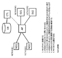
図1は、本発明の実施例1の構成を示すブロック図であり、2つの異なる無線端末ND1およびND2が、無線基地局APにアクセスし、ネットワークを経由して、サーバSV1およびSV2に接続する様子を概略的に示している。例えばノートPCやスマートホンである無線端末ND1およびND2は、同じ無線基地局APをネットワークへのアクセスポイントとして用い、ネットワークを経由して、2つの異なるサーバSV1およびSV2にそれぞれ接続される。本発明によると、無線端末ND1からサーバSV1への通信と無線端末ND1からサーバSV2への通信とを、論理的に分離することが可能である。以下では、どのような仕組みによって通信の論理的分離が可能になるのかについて、具体的な実施例を用いて説明する。 FIG. 1 is a block diagram showing the configuration of the first embodiment of the present invention. Two different wireless terminals ND1 and ND2 access the wireless base station AP and connect to the servers SV1 and SV2 via the network. The situation is shown schematically. For example, wireless terminals ND1 and ND2, which are notebook PCs and smart phones, are connected to two different servers SV1 and SV2 via the network using the same wireless base station AP as an access point to the network. According to the present invention, communication from the wireless terminal ND1 to the server SV1 and communication from the wireless terminal ND1 to the server SV2 can be logically separated. In the following, a mechanism that enables logical separation of communication will be described using a specific embodiment.
まず、無線端末ND1は、IEEE802.1aなどのWiFi通信(3GやLTEなどでも構わない)を用いて無線基地局APに通信リクエストを送信する。無線基地局APは、受信した通信リクエストから無線端末ND1を物理的に識別するMACアドレスを取得し、コントローラCTLに、無線基地局ND1の通信許可と、無線基地局ND1が利用できる仮想回線のネットワークアドレスとを求める。 First, the wireless terminal ND1 transmits a communication request to the wireless base station AP using WiFi communication such as IEEE802.1a (3G or LTE may be used). The radio base station AP acquires a MAC address for physically identifying the radio terminal ND1 from the received communication request, and allows the controller CTL to permit communication of the radio base station ND1 and a virtual circuit network that can be used by the radio base station ND1. Ask for an address .
コントローラCTLは、データベースDBを検索することにより、通信リクエストを送信してきた無線端末ND1の通信を許可すべきかどうか判断して、無線端末ND1の接続ネットワークアドレスNETADDR1を無線基地局APに返す。NETADDR1は、IPアドレスでも、MPLSなどのSIMヘッダでも構わない。無線基地局APは通信端末ND1にネットワークアドレスNETADDR1を与える。NETADDR1は、複数のネットワークアドレスで構成されるアドレスレンジの場合、そのアドレスレンジから一つのネットワークアドレスが、無線基地局APによって提供される。以上のようにして、無線基地局APは、無線端末ND1と同じネットワークアドレスレンジのSV1との間を接続する通信回路を構築し、無線端末ND1とサーバSV1とが通信できるようになる。この通信回路は予め作られていても構わない。同様に無線端末ND2はサーバSV2と通信出来るようになる。しかし、複数の無線端末と複数のサーバとの間の通信は相互に論理的に隔離されている。つまり、無線端末ND1やサーバSV1は、無線端末ND2やサーバSV2と通信することができない。 The controller CTL searches the database DB to determine whether or not the communication of the wireless terminal ND1 that has transmitted the communication request should be permitted, and returns the connection network address NETADDR1 of the wireless terminal ND1 to the wireless base station AP. NETADDR1 may be an IP address or a SIM header such as MPLS. The radio base station AP gives the network address NETADDR1 to the communication terminal ND1. In the case of NETADDR1, in the case of an address range composed of a plurality of network addresses, one network address is provided from the address range by the radio base station AP. As described above, the radio base station AP constructs a communication circuit that connects between the radio terminal ND1 and the SV1 having the same network address range, and the radio terminal ND1 and the server SV1 can communicate with each other. This communication circuit may be made in advance. Similarly, the wireless terminal ND2 can communicate with the server SV2. However, communications between a plurality of wireless terminals and a plurality of servers are logically isolated from each other. That is, the wireless terminal ND1 and the server SV1 cannot communicate with the wireless terminal ND2 and the server SV2.
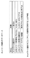
以上の処理をより詳細に説明する。コントローラCTLに接続された(または、内蔵された)データベースDBには、図2に示されているように、通信を許可する無線端末のMACアドレスと、そのMACアドレスを持つ無線端末が利用する仮想回線のネットワークアドレスと、無線基地局AP内で利用するポート番号とが予め格納されている。コントローラCTLは、MACアドレスをキーとしてデータベースDBを検索し、対応するネットワークアドレスとポート番号とを取得して、無線基地局APに与える。 The above process will be described in more detail. As shown in FIG. 2, the database DB connected (or built in) to the controller CTL has a MAC address of a wireless terminal that permits communication and a virtual that is used by a wireless terminal having the MAC address. The network address of the line and the port number used in the radio base station AP are stored in advance. The controller CTL searches the database DB using the MAC address as a key, acquires the corresponding network address and port number, and gives them to the radio base station AP.
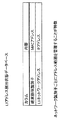
また、仮想回線を利用して無線基地局APを介したネットワークを構成する場合には、図3に示されているように、データベースDBには、仮想回線を構成する通信プロトコル、その通信プロトコルで利用する仮想回線のネットワークアドレス(例えば、L2ネットワーク仮想化識別子)が予め管理されていることになる。無線基地局APによって、無線端末ND1が利用するIPアドレスまたはIPアドレスレンジが与えられる場合には、L3ネットワークアドレス範囲をDBで管理しておく。これにより、コントローラCTLは、無線端末ND1のMACアドレスに基づく無線基地局APからの問い合わせに対し、利用する仮想回線ID(仮想化識別子)やそのプロトコルの種類(仮想化プロトコル)を、更には、必要な場合には無線端末ND1に割り当てるIPアドレスレンジを、無線基地局APに送信する。 When a network via the radio base station AP is configured using a virtual circuit, as shown in FIG. 3, the database DB includes a communication protocol that configures the virtual circuit, and its communication protocol. The network address (for example, L2 network virtualization identifier) of the virtual circuit to be used is managed in advance. When the wireless base station AP gives an IP address or an IP address range used by the wireless terminal ND1, the L3 network address range is managed in the DB. Thereby, the controller CTL, in response to the inquiry from the wireless base station AP based on the MAC address of the wireless terminal ND1, specifies the virtual circuit ID (virtualization identifier) to be used and the protocol type (virtualization protocol), If necessary, the IP address range assigned to the wireless terminal ND1 is transmitted to the wireless base station AP.
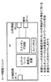
次に、コントローラCTLの機能とデータベースDBの構成との詳細を説明する。図4に示されているように、コントローラCTLは、フロー規制生成装置とフロー規制送信装置とを含む。データベースDBは、図2に示されている対応関係が格納されたMACアドレス・ネットワークアドレスデータベースと、図3に示されている対応関係が格納されたL3アドレス割当状態データベースとから構成される。 Next, details of the function of the controller CTL and the configuration of the database DB will be described. As shown in FIG. 4, the controller CTL includes a flow restriction generation device and a flow restriction transmission device. The database DB includes a MAC address / network address database in which the correspondence shown in FIG. 2 is stored and an L3 address allocation state database in which the correspondence shown in FIG. 3 is stored.
コントローラCTLは、無線基地局APからのMACアドレスに基づく問い合わせに対し、フロー規制生成装置により、無線端末ND1が利用できる通信(フロー)を制御する。具体的には、MACアドレス・ネットワークアドレスデータベースを利用し、該当するMACアドレスに対して仮想回線IDと無線基地局AP上で利用するポート情報とを生成する。コントローラCTLは、フロー規制送信装置を利用して生成したこれらの情報を、無線基地局APに送信する。 In response to an inquiry based on the MAC address from the radio base station AP, the controller CTL controls communication (flow) that can be used by the radio terminal ND1 by the flow restriction generation device. Specifically, a MAC address / network address database is used to generate a virtual circuit ID and port information used on the radio base station AP for the corresponding MAC address. The controller CTL transmits these pieces of information generated using the flow restriction transmitting device to the radio base station AP.
無線基地局APから無線端末ND1にIPアドレスまたはIPアドレスレンジを割り当てる必要がある場合には、コントローラCTLの中のフロー規制生成装置がL3アドレス割当状態データベースを検索して、無線端末ND1に割り当てるIPアドレスまたはIPアドレスレンジを決定し、フロー規制送信装置から無線基地局APに、割り当てられたIPアドレスまたはIPアドレスレンジを送信する。 When it is necessary to assign an IP address or an IP address range from the wireless base station AP to the wireless terminal ND1, the flow regulation generation device in the controller CTL searches the L3 address assignment state database and assigns the IP address to the wireless terminal ND1. An address or an IP address range is determined, and the assigned IP address or IP address range is transmitted from the flow restriction transmitter to the radio base station AP.
次に、上記CTLより送信された情報に基づく無線基地局APの動作について説明する。図5は無線基地局APの構成図である。図5の右端にある有線ポートはサーバSV1やSV2に接続され、または、他のネットワーク装置を経由してサーバSV1およびSV2と通信する。無線基地局APは、制御ポートを介してコントローラCTLと接続され通信するが、必要に応じて、有線ポートを介してCTLと接続される場合もある。無線ポートは、WiFiなどの無線プロトコルを介して複数の無線端末ND1やND2と通信する。CTLより受信する仮想回線IDとポート番号は、フローDBに記録される。フローは、個々の無線端末が利用することになる仮想回線IDとポート番号とによって管理される。フローDBに記録された仮想回線IDに基づいて、L2ネットワーク仮想化装置により仮想回線が形成される。この際、有線ポートを出力ポートとして仮想回線が形成される。フローDBの構成は、図6に示されている。 Next, the operation of the radio base station AP based on the information transmitted from the CTL will be described. FIG. 5 is a configuration diagram of the radio base station AP. The wired port at the right end of FIG. 5 is connected to the servers SV1 and SV2, or communicates with the servers SV1 and SV2 via other network devices. The radio base station AP is connected to and communicates with the controller CTL via the control port, but may be connected to the CTL via a wired port as necessary. The wireless port communicates with a plurality of wireless terminals ND1 and ND2 via a wireless protocol such as WiFi. The virtual circuit ID and port number received from the CTL are recorded in the flow DB. The flow is managed by a virtual circuit ID and a port number used by each wireless terminal. Based on the virtual line ID recorded in the flow DB, a virtual line is formed by the L2 network virtualization apparatus. At this time, a virtual line is formed using the wired port as an output port. The configuration of the flow DB is shown in FIG.
コントローラCTLから受信するIPアドレスまたはIPアドレスレンジは、L3アドレス割当装置を介して個々の無線端末に割り当てられる。割り当てられたIPアドレスまたはIPアドレスレンジは無線端末で利用される。マッチング回路では、未知のMACアドレスを無線端末より受信した場合に、制御ポートを介してコントローラCTLに通信許可とフロー制御やIPアドレスの新たな割り当てを要求する。また、マッチング回路では、無線基地局APで管理されたフロー(フローDB内に記録されたフロー)に対して、個々の仮想回線とIPアドレスを接続する。これにより、個々の無線端末とそれぞれの無線端末に対応するサーバとの間で、論理的に隔離された通信環境の中で通信出来るようになり、通信セキュリティが格段に向上する。 The IP address or IP address range received from the controller CTL is assigned to each wireless terminal via the L3 address assignment device. The assigned IP address or IP address range is used by the wireless terminal. When an unknown MAC address is received from a wireless terminal, the matching circuit requests communication permission, flow control, and new assignment of an IP address from the controller CTL via the control port. The matching circuit connects individual virtual lines and IP addresses to flows managed by the radio base station AP (flows recorded in the flow DB). As a result, communication can be performed in a logically isolated communication environment between each wireless terminal and a server corresponding to each wireless terminal, and communication security is greatly improved.
なお、以上の説明では、無線基地局APを介してコントローラCTLから無線端末ND1やND2にIPアドレスまたはIPアドレスレンジを割り当てた。しかし、IPアドレスまたはIPアドレスレンジは、サーバSV1やSV2によって割り当てられてもよい。サーバによる割り当てがなされる場合には、サーバに、図7に示されたデータが予め格納されている。この場合、コントローラCTLから無線基地局APへはフロー情報である仮想回線のネットワークアドレスとポート情報とが送信され、無線端末とサーバとの間は、仮想回線を介して接続される。次に、無線端末からはDHCPなどのプロトコルを通じて、サーバに利用するIPアドレスの問い合わせを行い、サーバは、図7の情報を用いて、問い合わせに来た無線端末のMACアドレスに基づいてIPアドレスを払い出す。 In the above description, an IP address or an IP address range is assigned from the controller CTL to the wireless terminals ND1 and ND2 via the wireless base station AP. However, the IP address or IP address range may be assigned by the servers SV1 and SV2. When the allocation by the server is performed, the data shown in FIG. 7 is stored in advance in the server. In this case, the network address and port information of the virtual line, which is flow information, are transmitted from the controller CTL to the radio base station AP, and the wireless terminal and the server are connected via the virtual line. Next, the IP address used for the server is inquired from the wireless terminal through a protocol such as DHCP, and the server uses the information shown in FIG. 7 to obtain the IP address based on the MAC address of the inquiring wireless terminal. Pay out.
以上で本発明による無線基地局APの動作の概略を説明したが、個別的な処理が図8のフローチャートに示されている。図8に示されているように、APでパケットを受信した場合、受信ポートが有線ポートからのものか、無線ポートからのものかを判定する。有線ポートからパケットを受信した場合には、宛先MACルールマッチング処理により通信先の無線端末のMACアドレスが登録されているかどうかを判断し、登録されてない場合には受信パケットを破棄する。一方で宛先MACルールマッチングに登録されている場合には、仮想ネットワークのヘッダを除去(仮想ネットワークのトンネルを除去)して、対象となる無線端末の無線ポートへパケットを送出する。 Although the outline of the operation of the radio base station AP according to the present invention has been described above, individual processing is shown in the flowchart of FIG. As shown in FIG. 8, when the AP receives a packet, it determines whether the reception port is from a wired port or a wireless port. When a packet is received from the wired port, it is determined whether or not the MAC address of the communication destination wireless terminal is registered by destination MAC rule matching processing. If the packet is not registered, the received packet is discarded. On the other hand, if it is registered for destination MAC rule matching, the header of the virtual network is removed (the tunnel of the virtual network is removed), and the packet is transmitted to the wireless port of the target wireless terminal.
一方で、無線ポートからパケットを受信した場合には、送信元MACルールマッチングにより、既に登録されている場合には、アドレス要求パケット処理によりIPアドレスを割り当てる要求のパケットかどうかを判断し、IPアドレス要求のパケットであれば、アドレス割当処理にてIPアドレス、またはIPアドレスレンジを割り当てる。受信したパケットがアドレス要求パケットではない場合には、仮想ネットワーク回線にトンネリング処理するために、L2仮想化ヘッダ挿入し、有線ポートへパケットを送出する。 On the other hand, when a packet is received from the wireless port, if it is already registered by the source MAC rule matching, it is determined whether it is a request packet for assigning an IP address by address request packet processing, and the IP address If it is a request packet, an IP address or an IP address range is assigned by address assignment processing. If the received packet is not an address request packet, an L2 virtualization header is inserted and the packet is transmitted to the wired port for tunneling processing to the virtual network line.
また、送信元MACルールマッチングにて、登録されていないパケットの場合には、コントローラCTLにMACアドレス問合せを実施し、フロールールを受信し、ルール種別にてルールの登録許可の場合には、ルールを登録し、ルール種別にてルール登録拒絶の場合には、パケットを破棄する。 In addition, in the case of a packet that is not registered by the source MAC rule matching, the controller CTL is inquired of the MAC address, the flow rule is received, and the rule type is permitted to register the rule. If the rule type is rejected by the rule type, the packet is discarded.
また、IPアドレスを割り当てる際の処理フローチャートが図9に示されている。アクセスポイントAPからコントローラCTLにIPアドレス、またはIPアドレスレンジを要求する場合には、CTLにアドレス要求を出し、その結果としてCTLより返答受信する。返答受信した結果、IPアドレス、またはIPアドレスレンジの割当に成功した場合には、無線端末にアドレス割当の情報を送出する。IPアドレス、またはIPアドレスレンジの割当に失敗した場合には、パケット破棄処理により、無線端末への応答を中止したり、割当失敗を通知したりする。 Further, FIG. 9 shows a processing flowchart for assigning an IP address. When an IP address or IP address range is requested from the access point AP to the controller CTL, an address request is issued to the CTL, and as a result, a response is received from the CTL. As a result of receiving the response, if the assignment of the IP address or the IP address range is successful, the address assignment information is transmitted to the wireless terminal. When allocation of an IP address or IP address range fails, response to the wireless terminal is canceled or allocation failure is notified by packet discard processing.
更に、フロー設定とIPアドレスの問合せ処理のシーケンス図が図10に示されている。無線端末NDは、アクセスポイントAPに無線接続した後にアドレス要求をおこなう。APはNDのMACアドレスの情報を検索・認証キーとして、コントローラCTLにMAC問合せをおこない、CTLからAPにフロールールが送信される。フロールールはAP内で登録などの処理が行われる。続いてAPからCTLに対してアドレス要求を行い、CTLからAPに対してIPアドレス、またはIPアドレスレンジのアドレス割当てを行う。続いて、APからNDに対してIPアドレス、またはIPアドレスレンジのアドレス割当てを行う。続いてNDからサーバSVへのアクセス処理が開始され、APを介して仮想ネットワーク回線等を通してSVにサーバアクセス情報が送信される。SVからサーバアクセスに対するサーバレスポンスがAPに送信され、APはそのサーバレスポンスをNDに送信する。 Further, a sequence diagram of the flow setting and IP address inquiry processing is shown in FIG. The wireless terminal ND makes an address request after wirelessly connecting to the access point AP. The AP makes a MAC inquiry to the controller CTL using the ND MAC address information as a search / authentication key, and the flow rule is transmitted from the CTL to the AP. The flow rule is subjected to processing such as registration within the AP. Subsequently, the AP issues an address request to the CTL, and the CTL assigns an IP address or IP address range to the AP. Subsequently, an IP address or an IP address range is assigned to the ND from the AP. Subsequently, an access process from the ND to the server SV is started, and server access information is transmitted to the SV through the virtual network line or the like via the AP. A server response to the server access is transmitted from the SV to the AP, and the AP transmits the server response to the ND.
以上は、図1のネットワーク構成に基づく実施例1について説明を行ったが、次に、図11に示されている異なるネットワーク構成の実施例2の場合について説明する。図11の構成と図1の構成との違いは、図11では、無線基地局APにネットワーク装置であるルータRTが接続され、サーバSV1やSV2がルータに接続されていることである。処理のシーケンスの違いは、CTLからRTに対して、RT上で設定するフロー情報である仮想回線のネットワークアドレスと利用するポート(必要に応じて仮想化プロトコルの種類の情報)が送信されることである。そして、APとRT間で仮想回線が形成されることである。 The first embodiment based on the network configuration of FIG. 1 has been described above. Next, the case of the second embodiment having a different network configuration shown in FIG. 11 will be described. The difference between the configuration of FIG. 11 and the configuration of FIG. 1 is that, in FIG. 11, a router RT, which is a network device, is connected to the radio base station AP, and servers SV1 and SV2 are connected to the router. The difference in the processing sequence is that the network address of the virtual circuit and the port to be used (virtualization protocol type information as required) are transmitted from the CTL to the RT as flow information set on the RT. It is. Then, a virtual line is formed between the AP and RT.
実施例2では、WiFi無線端末ND1が無線基地局APにWiFiまたは3GやLTE無線通信を利用して接続する。無線基地局APは無線通信を用いてND1の個体識別ID(MACアドレス)を取得し、APの制御システムCTLにMACアドレスを識別にした通信許可を問い合わせる。CTLはMACアドレス毎の通信許可を登録したデータベースDBを用いて通信許可を判断し、APとルータRT間の論理トンネルを作成しND1がリモートに位置するサーバSV1とEthernet(登録商標)などで接続できるようにする。このトンネルは予め作られていても構わない。Ethernetの代わりにVLANやATM回線レベルで接続するようにしても構わない。 In the second embodiment, the WiFi wireless terminal ND1 connects to the wireless base station AP using WiFi, 3G, or LTE wireless communication. The radio base station AP acquires the individual identification ID (MAC address) of the ND 1 using radio communication, and inquires the AP control system CTL about communication permission with the MAC address identified. The CTL determines the communication permission using the database DB in which the communication permission for each MAC address is registered, creates a logical tunnel between the AP and the router RT, and connects the server SV1 where the ND1 is located remotely to the Ethernet (registered trademark) or the like. It can be so. This tunnel may be created in advance. Instead of Ethernet, connection may be made at the VLAN or ATM line level.
EthernetレベルでND1とSV1が接続された後、SV1からND1に対してNETADDR1を払い出す。NETADDR1はIPアドレスでも、MPLSなどのSIMヘッダでも構わない。NETADDR1は、複数のネットワークアドレスで構成されるアドレスレンジの場合、そのアドレスレンジから一つのネットワークアドレスがAPにより払いださせる。このようにして、APはND1と同じネットワークアドレスレンジのSV1間を接続する通信回路を構築し、ND1はサーバSV1と通信できるようになる。同様に無線端末ND2はサーバSV2と通信出来るようになる。しかし、実施例1の場合と同様に、この実施例2でも、上記ND1とSV1は、ND2やSV2と通信することが出来ず、隔離される通信回路を構築できる。 After ND1 and SV1 are connected at the Ethernet level, NETADDR1 is paid out from SV1 to ND1. NETADDR1 may be an IP address or a SIM header such as MPLS. In the case of an address range composed of a plurality of network addresses, NETADDR1 allows one network address to be paid out by the AP from the address range. In this way, the AP constructs a communication circuit that connects SV1 having the same network address range as ND1, and ND1 can communicate with server SV1. Similarly, the wireless terminal ND2 can communicate with the server SV2. However, as in the case of the first embodiment, in the second embodiment also, the ND1 and SV1 cannot communicate with the ND2 and SV2, and an isolated communication circuit can be constructed.
なお、図12には、ルータRTの構成図が示されている。制御ポートを介してCTLよりフロー設定情報を受信し、スイッチDBに格納する。スイッチDBの構成は、図13に示されている。RTは複数のSVポートを具備している。L2ネットワーク仮想化装置は、APとの間で仮想回線を構成する。スイッチング回路は、APで管理されたフロー(フローDB内に記録されたフロー)に対して、個々の仮想回線とIPアドレスを接続する。これにより、個々の無線端末とサーバと間で論理的に隔離された通信環境の中での通信が可能になる。 FIG. 12 shows a configuration diagram of the router RT. Flow setting information is received from the CTL via the control port and stored in the switch DB. The configuration of the switch DB is shown in FIG. The RT has a plurality of SV ports. The L2 network virtualization apparatus configures a virtual line with the AP. The switching circuit connects each virtual circuit and an IP address to a flow managed by the AP (a flow recorded in the flow DB). This enables communication in a communication environment logically isolated between each wireless terminal and the server.
図14には、実施例3が示されている。実施例2ではAPとRT間の論理トンネルがOSI上のレイヤ2であるEthernetやVLANやATMで構成されていたのと異なり、実施例3では、無線基地局APとルータRTとの間がVXLANやGREなどのレイヤ3で論理トンネルが構成されている。このように構成される場合であっても、本発明によると、個々の無線端末とサーバと間で論理的に隔離された通信環境の中での通信が可能になる。 FIG. 14 shows a third embodiment. In the second embodiment, the logical tunnel between the AP and the RT is composed of Ethernet, VLAN, or ATM, which is layer 2 on the OSI. In the third embodiment, the VXLAN is connected between the radio base station AP and the router RT. A logical tunnel is configured by layer 3 such as GRE. Even in such a case, according to the present invention, communication can be performed in a communication environment logically isolated between each wireless terminal and the server.
図15には、実施例4が示されている。実施例4は、複数のAPと複数のRTで構成するネットワークにおいて、上記実施例2と3の機能を実現するものである。このように構成される場合であっても、本発明によると、個々の無線端末とサーバと間で論理的に隔離された通信環境の中での通信が可能になる。 FIG. 15 shows a fourth embodiment. The fourth embodiment realizes the functions of the second and third embodiments in a network composed of a plurality of APs and a plurality of RTs. Even in such a case, according to the present invention, communication can be performed in a communication environment logically isolated between each wireless terminal and the server.
以上は、平成25年4月4日に出願した特願2013−078487号(以下では、「先の出願」と称する)に記載されていた内容である。先の出願に記載された発明は、上述されているように、論理的に隔離された複数の通信回線を形成するために、通信基地局(アクセスポイント)にアクセスしている通信端末の物理アドレスを用いることを特徴としていた。しかし、発明者は、先の出願の後に、更なる研究開発活動を継続した。その成果として、発明者は、通信端末の物理アドレスに加えて、その通信端末がどのアクセスポイントにアクセスしているのかというアクセスポイントの識別データも同時に考慮することで、より柔軟なネットワークの構築が可能になることを見いだした。すなわち、端末情報とアクセスポイント情報との組合せを用いることにより、先の出願に記載されていた発明によって達成された作用効果に加えて、追加的な作用効果が得られることを見いだしたのである。以下では、その新たな実施例について説明したい。 The above is the contents described in Japanese Patent Application No. 2013-078487 filed on April 4, 2013 (hereinafter referred to as “prior application”). In the invention described in the previous application, as described above, the physical address of the communication terminal accessing the communication base station (access point) in order to form a plurality of logically isolated communication lines. It was characterized by using. However, the inventor continued further research and development activities after the previous application. As a result, the inventor is able to construct a more flexible network by simultaneously considering the access point identification data indicating which access point the communication terminal is accessing in addition to the physical address of the communication terminal. I found it possible. That is, it has been found that by using a combination of terminal information and access point information, an additional effect can be obtained in addition to the effect achieved by the invention described in the previous application. In the following, the new embodiment will be described.
図16には、本出願で追加する第5の実施例の概略的な構成が、ブロック図として示されている。ただし、図16は、第1の通信端末と第2の通信端末とが同一のアクセスポイントにアクセスする場合である。この場合、第1の端末ND1がアクセスポイントAPに接続すると、アクセスポイントAPは、第1の端末ND1のMACアドレスと自分自身であるアクセスポイントAPに関するデータとの組合せ情報を用いて、コントローラCTLに問い合わせる。コントローラCTLは、データベースDBから得られるND1とAPとの組合せ情報に基づいて、接続ネットワークNETADDR1をアクセスポイントAPに返す。そして、アクセスポイントAPは第1の端末ND1にNETADDR1のIPアドレスを与える。こうして、アクセスポイントAPを経由して第1の通信端末ND1と第1のサーバSV1との間を接続する通信回線が構築され、第1の通信端末ND1と第1のサーバSV1とが通信することが可能になる。第2の通信端末ND2についても同様である。このように、図16の場合には、単に、第1の通信端末ND1と第2の通信端末ND2とが区別されるだけでない。アクセスポイントAPにアクセスしている第1の通信端末ND1にはどのようなネットワークアドレスを与え、アクセスポイントAPにアクセスしている第2の通信端末ND2にはどのようなネットワークアドレスを与えるのか、が問題になる。例えば、もし、同じ第1の通信端末ND1であっても、別のアクセスポイントAP’にアクセスする場合には、別のネットワークアドレスが付与される可能性がある。 FIG. 16 is a block diagram showing a schematic configuration of a fifth embodiment added in the present application. However, FIG. 16 shows a case where the first communication terminal and the second communication terminal access the same access point. In this case, when the first terminal ND1 connects to the access point AP, the access point AP uses the combination information of the MAC address of the first terminal ND1 and the data related to the access point AP that is itself to the controller CTL. Inquire. The controller CTL returns the connection network NETADDR1 to the access point AP based on the combination information of ND1 and AP obtained from the database DB. Then, the access point AP gives the IP address of NETADDR1 to the first terminal ND1. In this way, a communication line that connects the first communication terminal ND1 and the first server SV1 via the access point AP is constructed, and the first communication terminal ND1 and the first server SV1 communicate with each other. Is possible. The same applies to the second communication terminal ND2. Thus, in the case of FIG. 16, the first communication terminal ND1 and the second communication terminal ND2 are not simply distinguished from each other. Given what network address to the first communication terminal ND1 that is accessing the access point AP, or give any network addresses in the second communication terminal ND2 accessing the access point AP, but It becomes a problem. For example, even if the first communication terminal ND1 is the same, when accessing another access point AP ′, another network address may be given.
先の出願に記載された発明では、コントローラCTLに接続されたデータベースDBに格納されている通信端末のMACアドレスとネットワークアドレスとの対応関係が図2に示されていた。また、図3には、別のデータベースに格納されているネットワークアドレスに関する対応関係が示されていた。これに対して、アクセスポイントに関する情報も考慮する本実施例の場合の対応関係は、図17および図18に示されている。図17では、端末の物理アドレスの下に、アクセスポイントに関する情報が含まれている。アクセスポイント情報の具体例としては、IPアドレスやMACアドレスが考えられるし、それ以外の管理情報でもかまわない。図18は、図3と同一である。 In the invention described in the previous application, the correspondence between the MAC address and the network address of the communication terminal stored in the database DB connected to the controller CTL is shown in FIG. Further, FIG. 3 shows a correspondence relationship regarding network addresses stored in another database. On the other hand, the correspondence in the case of the present Example which also considers the information regarding an access point is shown by FIG. 17 and FIG. In FIG. 17, the information regarding an access point is contained under the physical address of the terminal. As a specific example of the access point information, an IP address or a MAC address can be considered, and other management information may be used. FIG. 18 is the same as FIG.
次に、図19にも、本実施例の概略的な構成がブロック図として示されている。ただし、同じ実施例ではあるが、図19は図16と異なり、同じ2つの通信端末が別のアクセスポイントにアクセスする場合であり、本実施例の特徴的な作用効果をより明瞭にするための図解である。図19の構成では、第1の通信端末ND1が第1のアクセスポイントAP1に接続すると、第1のアクセスポイントAP1は、第1の通信端末ND1のMACアドレスと第1のアクセスポイントAP1に関するデータとの組合せ情報に基づいてコントローラCTLに問い合わせる。コントローラCTLは、データベースDBから得た第1の通信端末ND1と第1のアクセスポイントAP1との組合せに対応するネットワークアドレスをAP1に返す。第1のアクセスポイントとルータRTとは、このネットワークアドレスを用いて、第1の通信端末ND1と第1のサーバSV1との間を接続する通信回線を構築する。第1の通信端末ND1は第1のサーバSV1にIPアドレスの払い出し要求を送出するが、第1のサーバSV1は、その要求に応答して、ND1にIPアドレスを払い出す。 Next, also in FIG. 19, a schematic configuration of the present embodiment is shown as a block diagram. However, although it is the same embodiment, FIG. 19 is different from FIG. 16 in the case where the same two communication terminals access different access points, in order to clarify the characteristic operational effects of this embodiment. It is an illustration. In the configuration of FIG. 19, when the first communication terminal ND1 connects to the first access point AP1, the first access point AP1 receives the MAC address of the first communication terminal ND1 and the data related to the first access point AP1. The controller CTL is inquired based on the combination information. The controller CTL returns the network address corresponding to the combination of the first communication terminal ND1 and the first access point AP1 obtained from the database DB to AP1. The first access point and the router RT use this network address to construct a communication line that connects the first communication terminal ND1 and the first server SV1. The first communication terminal ND1 sends an IP address payout request to the first server SV1, and the first server SV1 pays out an IP address to the ND1 in response to the request.
次に、同じ第1の通信端末ND1が、別のアクセスポイントである第2のアクセスポイントAP2に接続する場合である。この場合、第2のアクセスポイントAP2は、第1の通信端末ND1のMACアドレスと自分自身である第2のアクセスポイントAP1に関するデータとの組合せ情報に基づいてコントローラCTLに問い合わせる。コントローラCTLは、データベースDBから得た第1の通信端末ND1と第2のアクセスポイントAP2との組合せに対応するネットワークアドレスをAP2に返す。第2のアクセスポイントAP2とルータRTとは、このネットワークアドレスを用いて、第1の通信端末ND1と第2のサーバSV2との間を接続する通信回線を構築する。第1の通信端末ND1は第2のサーバSV2にIPアドレスの払い出し要求を送出し、その要求に応答して、第2のサーバSV2は第1の通信端末ND1にIPアドレスを払い出す。 Next, the same first communication terminal ND1 is connected to the second access point AP2, which is another access point. In this case, the second access point AP2 makes an inquiry to the controller CTL based on the combination information of the MAC address of the first communication terminal ND1 and the data relating to the second access point AP1 that is itself. The controller CTL returns to AP2 a network address corresponding to the combination of the first communication terminal ND1 and the second access point AP2 obtained from the database DB. The second access point AP2 and the router RT use this network address to construct a communication line that connects the first communication terminal ND1 and the second server SV2. The first communication terminal ND1 sends an IP address issue request to the second server SV2, and in response to the request, the second server SV2 issues an IP address to the first communication terminal ND1.
次に、本実施例のように、通信端末の物理アドレスだけでなく、その通信端末のよって接続されているアクセスポイントに関するデータも考慮し、これら2つのデータの組に基づいてネットワークアドレスを決定することで、どのような効果が得られるかを、いくつかの例を挙げることによって説明する。 Next, as in this embodiment, not only the physical address of the communication terminal but also the data related to the access point connected by the communication terminal is considered, and the network address is determined based on the set of these two data. What effects can be obtained will be described by giving some examples.
本実施例によると、第1に、従来では発見できなかった不正アクセスを発見できる。例えば、WiFiのアクセスポイントは、通信距離が一般的に20m程度であり、見晴らしが良い場合でも100m程度が限界である。そのために、ビル内のオフィスには、取締役室、応接室、実験室、営業会議室など、複数の箇所にアクセスポイントを設置する必要がある。例えば、実験エンジニアは1階の実験室に配置したアクセスポイントを経由する場合にのみ社内ネットワークにアクセスできる、というルールがある場合を想定しよう。この場合、実験エンジニアの端末であると称する端末から、5階の取締役室のアクセスポイント経由での通信要求があった場合には、拒絶する必要がある。この例では、(1)ユーザの端末ID(MACアドレスや個体識別番号(例えば、シリアル番号、IMEI、MEID、CDN、およびICCID)など)と、(2)アクセスポイントAPの識別データ(IPアドレス、MACアドレス、個体識別番号(例えば、シリアル番号、データパスID、ESSID、IMEI、MEID、CDN、およびICCID)など)との組合せを用いて、通信許可認証処理を行うことにより、不正アクセスを防止することが可能になる。なお、ここで挙げた端末およびアクセスポイントの識別データは、あくまでも例示であり、必要や状況に応じて別の識別データを用いることも可能である。また、アクセスポイント以外に、有線接続するL2スイッチや、L3スイッチの場合でも同様に不正アクセスを発見できる。 According to the present embodiment, firstly, it is possible to find unauthorized access that could not be found in the past. For example, the access point of WiFi generally has a communication distance of about 20 m, and even when the view is good, the limit is about 100 m. For this purpose, it is necessary to install access points in a plurality of locations such as a director's room, a reception room, a laboratory, and a business meeting room in an office in a building. For example, let's assume that there is a rule that an experiment engineer can access an in-house network only through an access point placed in a laboratory on the first floor. In this case, if there is a communication request via the access point of the board room on the 5th floor from a terminal that is said to be an experimental engineer's terminal, it must be rejected. In this example, (1) the terminal ID of the user (MAC address or individual identification number (for example, serial number, IMEI, MEID, CDN, and ICCID)), and (2) identification data (IP address, Unauthorized access is prevented by performing communication permission authentication processing using a combination of a MAC address and an individual identification number (for example, serial number, data path ID, ESSID, IMEI, MEID, CDN, and ICCID). It becomes possible. Note that the terminal and access point identification data listed here are merely examples, and other identification data may be used according to necessity or situation. In addition to an access point, unauthorized access can be found in the same way even in the case of an L2 switch or an L3 switch connected by wire.
本実施例によると、第2に、先の出願に記載された発明では依然として通信が困難となる可能性のあるときでも、アクセス状態を改善できる。先の出願に記載された発明では、MACアドレスやシリアル番号などを用いて端末だけを識別している。したがって、端末を識別することを通じてネットワークへの接続を許可または拒絶する。つまり、その端末が現在どこにあるのかという場所を特定した制御はできないため、特定の場所だけからの接続を許可するという制御は不可能である。本実施例による端末とアクセスポイントとの組に基づく認証が可能であれば、ある通信端末について、特定の場所(アクセスポイント)だけからのアクセスを許可することができる。逆に、ある場所(アクセスポイント)への接続については、特定の通信端末だけ許可することも可能になる。 According to the present embodiment, secondly, the access state can be improved even when communication may still be difficult in the invention described in the previous application. In the invention described in the previous application, only the terminal is identified using a MAC address, a serial number, or the like. Therefore, the connection to the network is permitted or denied through identifying the terminal. In other words, since it is not possible to control the location where the terminal is currently located, it is impossible to control the connection only from the specific location. If authentication based on a set of a terminal and an access point according to the present embodiment is possible, access from a specific location (access point) can be permitted for a certain communication terminal. Conversely, only a specific communication terminal can be permitted for connection to a certain place (access point).
本実施例によると、第3に、ある企業や団体における個人の所属部署や担当の変更を、アクセス権限に適切に反映させることができる。例えば、ある企業のオフィスビルにおいて、開発1部(1階)と開発2部(9階)とが存在し、それぞれが、相互に競合関係にある顧客(ライバルの自動車製造会社A社およびB社)のシステムを開発しているとする。エンジニアSは、2013年12月末までは開発1部に所属しており、その期間は、1階に設置されたAPやL2/L3スイッチからしかネットワーク接続させない運用を行っていたとする。ところが、エンジニアSが2014年1月から開発2部に異動になった場合には、9階に設置されたAPやL2/L3スイッチからしかネットワーク接続させない運用に変更する必要がある。このような場合、本実施例によると、エンジニアXの所属組織と利用端末とを関連させて2つのデータの組として管理することになる。この管理により、所属組織の情報がコントローラ(CTL)に通知され、上記のアクセス権限の制御を適切に行うことができる。 According to the present embodiment, thirdly, the change of the personal department or charge in a certain company or organization can be appropriately reflected in the access authority. For example, in an office building of a company, there are development department 1 (1st floor) and development 2 department (9th floor), each of which is a mutually competitive customer (competitor car manufacturers A and B). ) System. It is assumed that the engineer S belongs to the Development Department 1 until the end of December 2013, and during that period, the operation was performed by connecting to the network only from the AP and L2 / L3 switch installed on the first floor. However, when the engineer S is transferred to the development 2 department from January 2014, it is necessary to change the operation to connect to the network only from the AP or L2 / L3 switch installed on the 9th floor. In such a case, according to the present embodiment, the organization to which the engineer X belongs and the use terminal are related and managed as a set of two data. With this management, information on the organization to which the user belongs is notified to the controller (CTL), and the access authority can be appropriately controlled.
先の出願に記載されていた発明では、通信端末の物理アドレスを利用して論理的に独立な通信回線の構築を可能にしていた。しかし、以上で説明したように、更にアクセスポイントに関するデータも考慮し、端末の物理アドレスとアクセスポイントデータとの組を用いてネットワークアドレスを決定するという特徴的な構成を採用することにより、更に多様な制御を可能にする柔軟な通信制御が可能になる。 In the invention described in the previous application, it is possible to construct a logically independent communication line using the physical address of the communication terminal. However, as described above, further consideration can be given to data relating to the access point, and by adopting a characteristic configuration in which the network address is determined using a set of the physical address of the terminal and the access point data, a further variety can be obtained. Flexible communication control that enables simple control.
Claims (4)
前記複数の通信端末のためのアクセスポイントとして機能する複数の通信基地局と、
前記複数の通信端末のそれぞれを物理的に識別する物理アドレスと前記複数の通信基地局のそれぞれを識別するデータとのすべての組合せと、前記組合せのそれぞれが用いることができるネットワークのネットワークアドレスとの対応関係が記憶されているデータベースと、
前記複数の通信基地局の中の1つの通信基地局において前記複数の通信端末の中の1つの通信端末から受信された通信リクエストに応答して、前記通信リクエストに含まれている物理アドレスと前記通信リクエストを受信した前記1つの通信基地局を識別するデータとの組合せに対応するネットワークアドレスを前記データベースから取得し、取得された前記ネットワークアドレスを前記1つの通信端末に提供することにより、前記1つの通信端末が、前記1つの通信基地局と前記提供されたネットワークアドレスによって識別されるネットワークとを経由して通信することを可能にするように構成された通信制御手段と、を備えていることにより、
前記複数の通信端末のそれぞれが、相互に論理的に隔離されたネットワークを経由して通信をすることを可能にする通信システム。 Multiple communication terminals,
A plurality of communication base stations functioning as access points for the plurality of communication terminals;
All combinations of physical addresses that physically identify each of the plurality of communication terminals and data that identify each of the plurality of communication base stations, and network addresses of networks that can be used by each of the combinations A database storing correspondences;
In response to a communication request received from one communication terminal of the plurality of communication terminals in one communication base station of the plurality of communication base stations, the physical address included in the communication request and the By obtaining a network address corresponding to a combination with data identifying the one communication base station that has received the communication request from the database, and providing the obtained network address to the one communication terminal, the 1 Communication control means configured to allow one communication terminal to communicate via the one communication base station and the network identified by the provided network address; By
A communication system that enables each of the plurality of communication terminals to communicate via a network logically isolated from each other.
前記通信制御手段が、前記複数の通信基地局の中の1つの通信基地局において前記複数の通信端末の中の1つの通信端末から受信された通信リクエストに応答して、前記通信リクエストに含まれている物理アドレスと前記通信リクエストを受信した前記1つの通信基地局を識別するデータとの組合せに対応するネットワークアドレスを前記データベースから取得するステップと、
前記通信制御手段が、前記取得された前記ネットワークアドレスを前記1つの通信端末に提供することにより、前記1つの通信端末が前記提供されたネットワークアドレスによって識別されるネットワークを経由して通信することを可能にするステップと、を含んでいることにより、
前記複数の通信端末のそれぞれが、相互に論理的に隔離されたネットワークを経由して通信をすることを可能にする方法。 A plurality of communication terminals, a plurality of communication base stations that function as access points for the plurality of communication terminals, a physical address that physically identifies each of the plurality of communication terminals, and each of the plurality of communication base stations A database storing a correspondence relationship between a combination of data for identifying the network and a network address of a network that can be used by each of the combinations, and logical isolation from each of the plurality of communication terminals via the network A communication control means comprising a communication control means for forming a plurality of communication lines,
The communication control means is included in the communication request in response to a communication request received from one communication terminal of the plurality of communication terminals in one communication base station of the plurality of communication base stations. Obtaining from the database a network address corresponding to a combination of a physical address and data identifying the one communication base station that received the communication request;
The communication control means provides the acquired network address to the one communication terminal, whereby the one communication terminal communicates via a network identified by the provided network address. Including enabling steps,
A method of enabling each of the plurality of communication terminals to communicate via a network logically isolated from each other.
Priority Applications (1)
| Application Number | Priority Date | Filing Date | Title |
|---|---|---|---|
| JP2013226219A JP5937563B2 (en) | 2013-04-04 | 2013-10-31 | Communication base station and control method thereof |
Applications Claiming Priority (3)
| Application Number | Priority Date | Filing Date | Title |
|---|---|---|---|
| JP2013078487 | 2013-04-04 | ||
| JP2013078487 | 2013-04-04 | ||
| JP2013226219A JP5937563B2 (en) | 2013-04-04 | 2013-10-31 | Communication base station and control method thereof |
Related Child Applications (1)
| Application Number | Title | Priority Date | Filing Date |
|---|---|---|---|
| JP2016052382A Division JP2016119722A (en) | 2013-04-04 | 2016-03-16 | Communication base station and control method thereof |
Publications (2)
| Publication Number | Publication Date |
|---|---|
| JP2014212507A JP2014212507A (en) | 2014-11-13 |
| JP5937563B2 true JP5937563B2 (en) | 2016-06-22 |
Family
ID=51931939
Family Applications (2)
| Application Number | Title | Priority Date | Filing Date |
|---|---|---|---|
| JP2013226219A Active JP5937563B2 (en) | 2013-04-04 | 2013-10-31 | Communication base station and control method thereof |
| JP2016052382A Pending JP2016119722A (en) | 2013-04-04 | 2016-03-16 | Communication base station and control method thereof |
Family Applications After (1)
| Application Number | Title | Priority Date | Filing Date |
|---|---|---|---|
| JP2016052382A Pending JP2016119722A (en) | 2013-04-04 | 2016-03-16 | Communication base station and control method thereof |
Country Status (1)
| Country | Link |
|---|---|
| JP (2) | JP5937563B2 (en) |
Families Citing this family (3)
| Publication number | Priority date | Publication date | Assignee | Title |
|---|---|---|---|---|
| JPWO2016152912A1 (en) * | 2015-03-26 | 2017-05-25 | 株式会社Nttドコモ | Communication system and communication method |
| JP6717548B2 (en) * | 2017-07-21 | 2020-07-01 | 日本電信電話株式会社 | Traffic control system and method |
| JPWO2022195651A1 (en) * | 2021-03-15 | 2022-09-22 |
Family Cites Families (3)
| Publication number | Priority date | Publication date | Assignee | Title |
|---|---|---|---|---|
| JP4825501B2 (en) * | 2005-11-25 | 2011-11-30 | 株式会社タムラ製作所 | Wireless LAN access point, IP address management method and management program using the same |
| JP5526047B2 (en) * | 2011-01-26 | 2014-06-18 | アラクサラネットワークス株式会社 | Packet relay apparatus and output destination determination method in packet relay apparatus |
| WO2013008770A1 (en) * | 2011-07-11 | 2013-01-17 | 日本電気株式会社 | Network quarantine system, network quarantine method and program therefor |
-
2013
- 2013-10-31 JP JP2013226219A patent/JP5937563B2/en active Active
-
2016
- 2016-03-16 JP JP2016052382A patent/JP2016119722A/en active Pending
Also Published As
| Publication number | Publication date |
|---|---|
| JP2016119722A (en) | 2016-06-30 |
| JP2014212507A (en) | 2014-11-13 |
Similar Documents
| Publication | Publication Date | Title |
|---|---|---|
| US10616077B2 (en) | System architecture and methods for controlling and managing networking devices and expediting new service delivery in a subscriber's home network using micro-domains | |
| JP6718966B2 (en) | Methods for establishing a roaming connection | |
| EP3641365B1 (en) | Device access method, device and system | |
| CN107733670B (en) | Forwarding strategy configuration method and device | |
| CN108781178B (en) | Network system, control device, method for constructing virtual network function, and program | |
| US20150032861A1 (en) | Device Abstraction in Autonomous Wireless Local Area Networks | |
| JP7296993B2 (en) | Communication method and communication device | |
| US20170005981A1 (en) | Address identifier allocation method, related device, and system | |
| CN110166414B (en) | Communication method, device and system | |
| CN105794149B (en) | Data network, network controller and method for managing routing device | |
| US20120257565A1 (en) | Mobile network traffic management | |
| CN108702322B (en) | Network system, terminal, sensor data collection method, and program | |
| CN114080054A (en) | PDU session establishment method, terminal equipment and chip system | |
| CN108702323B (en) | Network system, control device, virtual network construction method, and computer-readable storage medium | |
| JP5937563B2 (en) | Communication base station and control method thereof | |
| US20240098806A1 (en) | Service data flow continuity for a ue in a system involving a gateway device | |
| US7940760B2 (en) | Method and apparatus for discovering component in at least one sub-network | |
| CN114040450A (en) | Communication method and device | |
| US10516998B2 (en) | Wireless network authentication control | |
| US20160028650A1 (en) | Method and system for a user to create favorite server lists for multiple services | |
| CN114365454A (en) | Distribution of stateless security functions | |
| US20240098583A1 (en) | PDU session continuity for a UE moving between a telecommunications network and a gateway device | |
| KR102560953B1 (en) | Enterprise network security connection device and network classification access method through it | |
| US20210336851A1 (en) | Globally-Distributed Secure End-To-End Identity-Based Overlay Network | |
| US20210119859A1 (en) | Topology Agnostic Security Services |
Legal Events
| Date | Code | Title | Description |
|---|---|---|---|
| A131 | Notification of reasons for refusal |
Free format text: JAPANESE INTERMEDIATE CODE: A131 Effective date: 20141202 |
|
| A521 | Request for written amendment filed |
Free format text: JAPANESE INTERMEDIATE CODE: A523 Effective date: 20150202 |
|
| A131 | Notification of reasons for refusal |
Free format text: JAPANESE INTERMEDIATE CODE: A131 Effective date: 20150624 |
|
| A711 | Notification of change in applicant |
Free format text: JAPANESE INTERMEDIATE CODE: A711 Effective date: 20150630 |
|
| A521 | Request for written amendment filed |
Free format text: JAPANESE INTERMEDIATE CODE: A821 Effective date: 20150630 |
|
| A521 | Request for written amendment filed |
Free format text: JAPANESE INTERMEDIATE CODE: A523 Effective date: 20150824 |
|
| A02 | Decision of refusal |
Free format text: JAPANESE INTERMEDIATE CODE: A02 Effective date: 20151216 |
|
| A521 | Request for written amendment filed |
Free format text: JAPANESE INTERMEDIATE CODE: A523 Effective date: 20160316 |
|
| A911 | Transfer to examiner for re-examination before appeal (zenchi) |
Free format text: JAPANESE INTERMEDIATE CODE: A911 Effective date: 20160325 |
|
| TRDD | Decision of grant or rejection written | ||
| A01 | Written decision to grant a patent or to grant a registration (utility model) |
Free format text: JAPANESE INTERMEDIATE CODE: A01 Effective date: 20160427 |
|
| A61 | First payment of annual fees (during grant procedure) |
Free format text: JAPANESE INTERMEDIATE CODE: A61 Effective date: 20160512 |
|
| R150 | Certificate of patent or registration of utility model |
Ref document number: 5937563 Country of ref document: JP Free format text: JAPANESE INTERMEDIATE CODE: R150 |
|
| R250 | Receipt of annual fees |
Free format text: JAPANESE INTERMEDIATE CODE: R250 |
|
| R250 | Receipt of annual fees |
Free format text: JAPANESE INTERMEDIATE CODE: R250 |
|
| R250 | Receipt of annual fees |
Free format text: JAPANESE INTERMEDIATE CODE: R250 |
|
| R250 | Receipt of annual fees |
Free format text: JAPANESE INTERMEDIATE CODE: R250 |
|
| R250 | Receipt of annual fees |
Free format text: JAPANESE INTERMEDIATE CODE: R250 |
|
| R250 | Receipt of annual fees |
Free format text: JAPANESE INTERMEDIATE CODE: R250 |