JP5935682B2 - Display control apparatus, display control method, and program - Google Patents
Display control apparatus, display control method, and program Download PDFInfo
- Publication number
- JP5935682B2 JP5935682B2 JP2012275539A JP2012275539A JP5935682B2 JP 5935682 B2 JP5935682 B2 JP 5935682B2 JP 2012275539 A JP2012275539 A JP 2012275539A JP 2012275539 A JP2012275539 A JP 2012275539A JP 5935682 B2 JP5935682 B2 JP 5935682B2
- Authority
- JP
- Japan
- Prior art keywords
- display
- screen
- display control
- output
- display screen
- Prior art date
- Legal status (The legal status is an assumption and is not a legal conclusion. Google has not performed a legal analysis and makes no representation as to the accuracy of the status listed.)
- Active
Links
Images


Classifications
-
- G—PHYSICS
- G06—COMPUTING; CALCULATING OR COUNTING
- G06F—ELECTRIC DIGITAL DATA PROCESSING
- G06F3/00—Input arrangements for transferring data to be processed into a form capable of being handled by the computer; Output arrangements for transferring data from processing unit to output unit, e.g. interface arrangements
- G06F3/14—Digital output to display device ; Cooperation and interconnection of the display device with other functional units
- G06F3/1454—Digital output to display device ; Cooperation and interconnection of the display device with other functional units involving copying of the display data of a local workstation or window to a remote workstation or window so that an actual copy of the data is displayed simultaneously on two or more displays, e.g. teledisplay
-
- G—PHYSICS
- G06—COMPUTING; CALCULATING OR COUNTING
- G06T—IMAGE DATA PROCESSING OR GENERATION, IN GENERAL
- G06T3/00—Geometric image transformation in the plane of the image
- G06T3/40—Scaling the whole image or part thereof
-
- G—PHYSICS
- G09—EDUCATION; CRYPTOGRAPHY; DISPLAY; ADVERTISING; SEALS
- G09G—ARRANGEMENTS OR CIRCUITS FOR CONTROL OF INDICATING DEVICES USING STATIC MEANS TO PRESENT VARIABLE INFORMATION
- G09G2340/00—Aspects of display data processing
- G09G2340/14—Solving problems related to the presentation of information to be displayed
- G09G2340/145—Solving problems related to the presentation of information to be displayed related to small screens
-
- H—ELECTRICITY
- H04—ELECTRIC COMMUNICATION TECHNIQUE
- H04M—TELEPHONIC COMMUNICATION
- H04M2250/00—Details of telephonic subscriber devices
- H04M2250/16—Details of telephonic subscriber devices including more than one display unit
Description
本開示は、表示制御装置、表示制御方法及びプログラムに関する。 The present disclosure relates to a display control device, a display control method, and a program.
一般的に、パーソナルコンピュータ(PC)、タブレット端末、携帯電話、スマートフォン、デジタルカメラ、デジタルビデオカメラ等の情報処理装置における表示画面のレイアウトは、予め設定された基準値に応じて制御される。例えば、メニュー画面や各操作画面に含まれるアイコンの大きさや配置は、予め設定された基準値に応じて所定の大きさで所定の位置に配置される。 Generally, the layout of a display screen in an information processing apparatus such as a personal computer (PC), a tablet terminal, a mobile phone, a smartphone, a digital camera, or a digital video camera is controlled according to a preset reference value. For example, the size and arrangement of the icons included in the menu screen and each operation screen are arranged at a predetermined position with a predetermined size according to a preset reference value.
ここで、表示領域全体のサイズが変更された場合に、タイトルバー、メニューバー等が大きくなり、メニューバーがウィンドウの横のサイズを超えてしまい、選択できなくなる等の不具合が生じていた。これに対し、下記特許文献1では、プログラム実行中に、ウィンドウ画面変更通知を受け取り、自動的に表示領域を計算し、新しい設定の画面サイズに応じてメニューバーの横方向のサイズやタイトルバーのサイズを見直す更新システムが開示されている。
Here, when the size of the entire display area is changed, the title bar, the menu bar, and the like become large, and the menu bar exceeds the horizontal size of the window, which causes problems such as being unable to be selected. On the other hand, in
しかしながら、上記特許文献1では表示領域全体のサイズ変更に応じてタイトルバーやメニューの表示サイズを最適なサイズに変更する点については言及されているが、表示される情報の量を変更する点には言及されていない。
However, in the above-mentioned
また、近年、表示機能を有する情報処理装置と外部の表示デバイスを接続し、情報処理装置の表示画面を外部の表示デバイスに出力して利用する形態が見受けられるが、表示先の画面の大きさに合わせて表示サイズを変更するだけでは使い難いことが多かった。 In recent years, it has been seen that an information processing apparatus having a display function is connected to an external display device, and the display screen of the information processing apparatus is output to the external display device for use. In many cases, it was difficult to use simply by changing the display size to match.
そこで、本開示では、外部に出力する表示画面に含まれる情報の詳細度合いを変更することが可能な、新規かつ改良された表示制御装置、表示制御方法及びプログラムを提案する。 Therefore, the present disclosure proposes a new and improved display control device, display control method, and program capable of changing the degree of detail of information included in a display screen output to the outside.
本開示によれば、外部に表示画面を出力する出力部と、前記外部に出力する表示画面に含まれるオブジェクトを、現在表示画面に含まれる同オブジェクトの第1の表示態様と情報の詳細度合いにおいて異なる第2の表示態様に変更するよう制御する表示制御部と、を備える、表示制御装置を提案する。 According to the present disclosure, an output unit that outputs a display screen to the outside, and an object included in the display screen that is output to the outside, the first display mode of the object included in the current display screen and the degree of information detail A display control device comprising: a display control unit that controls to change to a different second display mode.
本開示によれば、外部に出力する表示画面に含まれるオブジェクトを、現在表示画面に含まれる同オブジェクトの第1の表示態様と情報の詳細度合いにおいて異なる第2の表示態様に変更するステップと、前記第2の表示態様に変更したオブジェクトを含む表示画面を外部に出力するステップと、を含む、表示制御方法を提案する。 According to the present disclosure, the step of changing the object included in the display screen to be output to the outside to a second display mode that differs from the first display mode of the object included in the current display screen in the degree of detailed information; And a step of outputting a display screen including the object changed to the second display mode to the outside.
本開示によれば、コンピュータに、外部に表示画面を出力する出力部と、前記外部に出力する表示画面に含まれるオブジェクトを、現在表示画面に含まれる同オブジェクトの第1の表示態様と情報の詳細度合いにおいて異なる第2の表示態様に変更するよう制御する表示制御部と、として機能させるための、プログラムを提案する。 According to the present disclosure, an output unit that outputs a display screen to the outside and an object included in the display screen that is output to the outside are displayed on the computer, and the first display mode and information of the object included in the current display screen are displayed. A program for functioning as a display control unit that controls to change to a second display mode that differs in the degree of detail is proposed.
以上説明したように本開示によれば、外部に出力する表示画面に含まれる情報の詳細度合いを変更することが可能となる。 As described above, according to the present disclosure, it is possible to change the degree of detail of information included in a display screen output to the outside.
以下に添付図面を参照しながら、本開示の好適な実施の形態について詳細に説明する。なお、本明細書及び図面において、実質的に同一の機能構成を有する構成要素については、同一の符号を付することにより重複説明を省略する。 Hereinafter, preferred embodiments of the present disclosure will be described in detail with reference to the accompanying drawings. In addition, in this specification and drawing, about the component which has the substantially same function structure, duplication description is abbreviate | omitted by attaching | subjecting the same code | symbol.
また、説明は以下の順序で行うものとする。
1.本開示の一実施形態による表示制御の概要
2.基本構成及び動作処理
2−1.デジタルカメラの構成
2−2.表示制御処理
3.画面表示例
3−1.第1の画面表示例
3−2.第2の画面表示例
3−3.第3の画面表示例
3−4.第4の画面表示例
3−5.第5の画面表示例
3−6.第6の画面表示例
3−7.第7の画面表示例
4.まとめ
The description will be made in the following order.
1. 1. Overview of display control according to an embodiment of the
<<1.本開示の一実施形態による表示制御の概要>>
まず、本開示の一実施形態による表示制御の概要について、図1を参照して説明する。
<< 1. Overview of display control according to an embodiment of the present disclosure >>
First, an overview of display control according to an embodiment of the present disclosure will be described with reference to FIG.
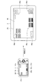
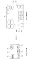
図1は、本開示の一実施形態による表示制御の概要を説明するための図である。図1に示すように、本実施形態によるデジタルカメラ1(表示制御装置)は、表示部19を有し、表示部19に例えばメニュー画面30を表示する。メニュー画面30は、メニュー項目31a、31b、31c、31d、31eを含み、各々予め設定された大きさで所定の位置に各々配置されている。
FIG. 1 is a diagram for describing an overview of display control according to an embodiment of the present disclosure. As shown in FIG. 1, the digital camera 1 (display control device) according to the present embodiment includes a
デジタルカメラ1は、表示画面を外部の表示デバイスに出力する機能を有する。外部の表示デバイスとは、例えば図1に示すようなタブレット端末2の他、スマートフォン、デジタルビデオカメラ、ノートPC、テレビジョン装置、またはプロジェクタ等である。
The
ここで、通常、出力元のデジタルカメラ1の表示領域より出力先の表示領域の方が大きい場合、出力先において出力元の表示画面がそのまま拡大表示される。以下、図2を参照して具体的に説明する。
Here, usually, when the display area of the output destination is larger than the display area of the
図2は、出力先において表示画面が拡大表示される場合について説明するための図である。図2に示すように、例えばデバイスAにおいて表示画面100が表示される場合、表示画面100に含まれる項目110a〜110eの大きさ及び配置は、予めデバイスAの表示領域に応じてユーザが使いやすいよう設定された大きさ及び配置である。
FIG. 2 is a diagram for explaining a case where the display screen is enlarged and displayed at the output destination. As shown in FIG. 2, for example, when the
一方、かかる表示画面100が、デバイスAより表示領域が大きいデバイスBに出力されると、図2に示すように、デバイスBにおいて表示画面200として表示画面100がデバイスBの表示領域に合わせて拡大表示される。これにより、表示画面200に含まれる項目210a〜210eも拡大表示され、ユーザにとっては項目210a〜210eが必要以上に大きく表示されるので使い難く、また、必要以上に大きな項目を表示することは、表示領域の無駄と言える。
On the other hand, when the
以上の事情を鑑みて、本開示による表示制御では、出力先の表示領域に応じて表示画面内に含まれる各オブジェクト(アイコン等)の大きさを調整し、さらに出力先の表示領域の大きさに応じて、より詳細な情報を提示するよう表示変更する。すなわち、図1に示すようなデジタルカメラ1に表示されるメニュー画面30は、小さな画面でも効果的に表示内容が認識されるよう、画面が階層化され、初期画面は表層のみが表示されている。デジタルカメラ1は、ユーザの選択に応じて次階層を表示していくので、ユーザは、選択を繰り返して目的の機能にたどり着くことができる。
In view of the above circumstances, in the display control according to the present disclosure, the size of each object (icon or the like) included in the display screen is adjusted according to the display area of the output destination, and further the size of the display area of the output destination The display is changed so as to present more detailed information. That is, the
そして、メニュー画面30が外部の大きな表示領域に出力される場合、当該大きな表示領域を効果的に利用する表示画面に変更することができれば、UI(ユーザインタフェース)の利便性が飛躍的に向上する。具体的には、本開示による表示制御において、初期画面に含む情報量を増加させるよう表示変更することで、ユーザは、直接またはより少ない選択操作で、意図する機能にたどり着くことができる。
When the
例えば、図1に示すように、デジタルカメラ1は、デジタルカメラ1の表示領域より大きい表示領域を有するタブレット端末2にメニュー画面30を出力する際、複数階層の機能を含むメニュー画面45に変更し、初期画面に含む情報量を増加させてもよい。タブレット端末2の表示部25に表示されるメニュー画面45は、図1に示すように、アイコン群46a、46c、46d、46eを含む。これら各アイコン群46a、46c、46d、46eは、メニュー項目31a、31c、31d、31eの各次階層の機能である。具体的には、例えばメニュー項目31aが「設定変更」の場合、アイコン群46aとして「日時設定」「言語設定」「画面の明るさ設定」「システム設定」といった機能が表示される。また、メニュー項目31cが「撮影メニュー」の場合、アイコン群46cとして「ISO感度設定」「色空間」「ノイズ低減」「露出」といった機能が表示される。また、メニュー項目31dが「再生メニュー」の場合、アイコン群46dとして「すべて再生」「カレンダー表示」といった機能が表示される。また、メニュー項目31eが「送信メニュー」の場合、アイコン群46eとして「すべて送信」「選択送信」「通信方式設定」といった機能が表示される。なお、表示画面45に含まれるアイコン46bは、メニュー項目31bの次階層が無い場合に同階層(初期階層)の状態のまま表示される例であって、図1に示すように、アイコンの大きさのみ調整され表示されている。例えば、メニュー項目31bが「ガイド表示」であって、次階層が無い場合も想定される。
For example, as illustrated in FIG. 1, when the
このように、タブレット端末2に表示されるメニュー画面45は、初期画面において複数階層の機能を含み、ユーザは、直接またはより少ない選択操作で意図する機能にたどり着くことができる。
As described above, the
また、メニュー画面45に含まれるアイコン群46a、46c、46d、46e、及びアイコン46bと、出力元のメニュー画面30に含まれるメニュー項目31a〜31eとの関連を示すために、本実施形態では各々の表示位置を対応させている。
In this embodiment, in order to show the relationship between the
以上、本開示の一実施形態における表示制御の概要について説明した。続いて、本実施形態による表示制御を実行するデジタルカメラ1(表示制御装置)の構成及び動作処理について順次説明する。なお、図1に示す例では、本実施形態による表示制御装置の一例としてデジタルカメラ1を図示したが、本実施形態による表示制御装置はこれに限定されず、例えばデジタルビデオカメラ、携帯電話、PHS(Personal Handy−phone System)、スマートフォン、PDA(Personal Digital Assistant)、またはノートPC等であってもよい。
The overview of display control according to an embodiment of the present disclosure has been described above. Next, the configuration and operation processing of the digital camera 1 (display control device) that performs display control according to the present embodiment will be sequentially described. In the example illustrated in FIG. 1, the
<<2.基本構成及び動作処理>>
<2−1.デジタルカメラの構成>
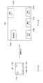
図3は、本実施形態によるデジタルカメラ1の内部構成例を示すブロック図である。図3に示すように、本実施形態によるデジタルカメラ1は、CPU(Central Processing Unit)10、ROM(Read Only Memory)11、RAM(Random Access Memory)12、カメラモジュール13、操作入力部14、記憶メディア16、表示制御部17、比較部18、表示部19、及び外部I/F(インターフェース)20を有する。以下、各構成について具体的に説明する。
<< 2. Basic configuration and operation processing >>
<2-1. Digital camera configuration>
FIG. 3 is a block diagram illustrating an internal configuration example of the
(カメラモジュール)
カメラモジュール13は、撮像素子、撮像レンズを含む撮像光学系、及び撮影画像信号処理部を含み、デジタル信号とされた撮影画像のデータを出力する。なお、撮像素子は、例えばCCD(Charge Coupled Device)イメージャやCMOS(Complementary Metal Oxide Semiconductor)イメージャにより実現される。
(The camera module)
The
(操作入力部)
操作入力部14は、ユーザによる操作入力を受け付ける機能を有する。具体的には、操作入力部14は、例えば電源スイッチ、撮影指示部、及び操作ボタン等である。撮影指示部は、カメラモジュール13による撮影処理をユーザが指示するためのものであって、例えばシャッターボタンであってもよい。また、操作入力部14は、表示部19と一体化された位置検出可能なタッチパネルであってもよい。
(Operation input section)
The
(記憶メディア)
記憶メディア16は、撮影された各記憶データを保持する画像記憶部であって、例えばカード型メモリなどのフラッシュメモリや、DVD(Digital Versatile Disc)などの記録媒体により実現される。記憶メディア16は、カメラモジュール13から連続的に出力される撮影画像を、シャッターボタンの操作タイミングに応じて、静止画像データ(写真)として保持してもよいし、動画像データ(ビデオ)として保持してもよい。
(Storage media)
The
(表示制御部)
表示制御部17は、CPU10の指示に従って、表示部19に表示する内容を制御する機能を有する。具体的には、表示部19に所定のメニュー画面や操作画面を表示したり、カメラモジュール13から出力された撮影画像をリアルタイムに表示したり、記憶メディア16に記憶されている画像データ(静止画/動画)を表示(再生)したりする制御を行う。
(Display control unit)
The
また、本実施形態による表示制御部17は、外部I/F20から外部に出力される表示画面を制御することも可能である。この際、表示制御部17は、外部に出力する表示画面に含まれるメニュー項目やアイコン等の各オブジェクトを、現在表示画面に含まれる同オブジェクトの第1の表示態様と情報の詳細度合いにおいて異なる第2の表示態様に変更するよう制御する。例えば、表示制御部17は、出力先の表示領域が現在表示画面の領域より大きい場合、外部に出力する表示画面に含まれるオブジェクトを、現在表示画面に含まれる同オブジェクトで示される情報より詳細な情報を示す(詳細度合いが高い)第2の表示態様に変更する。
The
より具体的には、例えば図1に示すメニュー画面30が、各オブジェクトが第1の表示態様で表示された現在表示画面であって、メニュー画面45が、各オブジェクトが第2の表示態様で表示された表示画面である。図1に示すように、出力先であるタブレット端末2の表示領域は、現在表示画面を表示するデジタルカメラ1の表示領域より大きい。したがって、表示制御部17は、タブレット端末2に出力されるメニュー画面を、詳細な情報を示す第2の表示態様として、複数階層を含む初期画面に変更する制御を行う。
More specifically, for example, the
なお、出力先の表示領域が現在表示画面の領域より大きいか否かについては、次に説明する比較部18から出力される比較結果に基づいて判断される。また、本明細書において、現在表示画面の領域とは、現在、表示制御部17により表示制御されている表示画面の表示領域であって、例えば現在、外部の一の表示装置に表示画面を出力している場合、当該外部の表示装置の表示領域が相当する。そして、表示(出力)先を外部の他の表示装置やデジタルカメラ1の表示部19に切り替える際、表示制御部17は、外部の一の表示装置の表示領域と、上記他の表示装置の表示領域やデジタルカメラ1の表示領域との大きさの比較に基づいて、表示態様の変更を行う。
Whether or not the display area of the output destination is larger than the area of the current display screen is determined based on the comparison result output from the
(比較部)
比較部18は、表示画面の出力先の表示領域の大きさと、現在表示画面の大きさとを比較する機能を有する。具体的には、比較部18は、外部I/F20を介して出力先の表示装置から表示領域に関する情報を取得し、出力先の表示領域の大きさと、現在表示画面の大きさとを比較する。
(Comparison part)
The
(表示部)
表示部19は、表示制御部17の制御により、所定のメニュー画面や操作画面、撮影画像等を表示(再生)する。また、表示部19は、例えばLCD(Liquid Crystal Display)またはOLED(Organic Light−Emitting Diode)等により実現される。
(Display section)
The
(外部I/F)
外部I/F20は、外部装置にデータを出力する出力部と、外部装置からデータを受け取ってデジタルカメラ1に当該データを入力する入力部との機能を有する。本実施形態による外部I/F20は、外部装置と有線または無線によりデータの入出力が可能である。無線通信としては、例えば無線LAN、赤外線、Wi−Fi、Bluetooth(登録商標)、または近距離無線通信等の通信方式が用いられる。
(External I / F)
The external I /
(CPU)
CPU10は、デジタルカメラ1の各構成を制御する制御部である。なお、上述した表示制御部17及び比較部18は、CPU10の具体的な機能としてCPU10に含まれてもよい。
(CPU)
The
(ROM、RAM)
ROM11には、CPU10が各処理を遂行するためのプログラム等が記憶されている。また、RAM12は、CPU10がROM11に記憶されているプログラムを実行する際に、ワークエリアとして用いられる。
(ROM, RAM)
The
以上、本実施形態によるデジタルカメラ1の構成について詳細に説明した。続いて、本実施形態によるデジタルカメラ1の動作処理について図4を参照して説明する。
Heretofore, the configuration of the
<2−2.表示制御処理>
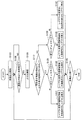
図4は、本実施形態による表示制御処理を示すフローチャートである。図4に示すように、まず、ステップS103において、デジタルカメラ1の表示制御部17は、CPU10の指示に応じて、表示部19へ画像出力を開始する。例えば、表示制御部17は、デジタルカメラ1の電源スイッチがONになった場合、図1に示すように、表示部19にメニュー画面30を表示する。
<2-2 . Display control processing >
FIG. 4 is a flowchart showing display control processing according to the present embodiment. As shown in FIG. 4, first, in step S <b> 103, the
次に、ステップS106において、デジタルカメラ1のCPU10は、画像出力状態に変更が発生したか否かを検知する。画像出力状態の変更とは、具体的には画像の出力先(表示先)の変更である。CPU10は、例えばユーザ操作により出力先の変更が指示された場合や、外部I/F20が外部の表示装置に接続された場合等に、画像の出力先の変更を検知する。
Next, in step S106, the
次いで、画像出力状態の変更が発生した場合(S106/Yes)、ステップS109において、CPU10は、出力先を確認する。具体的には、CPU10は、画像の出力先に対して情報要求を行い、出力先に関する情報を取得する。そしてCPU10は、出力先の表示領域の大きさに関する情報を比較部18に出力する。なお、出力先に関する情報が出力先から取得できない場合、CPU10は、ユーザに対して出力先に関する情報の入力を要求し、所望の情報を取得してもよい。
Next, when a change in the image output state occurs (S106 / Yes), in step S109, the
次に、ステップS112において、比較部18は、現在表示画面の領域の大きさと、出力先の表示領域の大きさとを比較し、比較結果を表示制御部17に出力する。そして、表示制御部17は、比較結果に基づいて、出力される表示画面に含まれる各オブジェクトの表示態様を変更する制御を行う。以下、ステップS125〜S142において具体的に説明する。
Next, in step S112, the
まず、現在表示画面の領域より出力先の表示領域の方が大きい場合(S112/Yes)、ステップS125において、表示制御部17は、出力先の表示領域が、中サイズか大サイズかを判断する。中サイズか大サイズかは、予め設定された中サイズ(例えば第1の閾値〜第2の閾値の間のサイズ)、大サイズ(例えば第2の閾値を上回るサイズ)のいずれに該当するかで判断されてもよい。
First, when the display area of the output destination is larger than the area of the current display screen (S112 / Yes), in step S125, the
次いで、大サイズの場合(S125/大)、ステップS128において、表示制御部17は、出力される表示画面に含まれる各オブジェクトを、大画面用のレイアウトに変更、すなわち、大画面用の表示態様に変更する。この際、表示制御部17は、出力先において、表示画面に含まれる各オブジェクトの表示態様の変化を表す遷移画面(アニメーション)を表示するよう制御してもよい。遷移画面が表示されることで、ユーザは、現在表示画面に含まれる各オブジェクトと、変更後の大画面に含まれる各オブジェクトとの関連を直感的に把握することができる。このような表示制御部17による遷移画面の表示や、変更後の表示態様については、後述の「3.画面表示例」において、具体例を挙げて説明する。
Next, in the case of a large size (S125 / large), in step S128, the
次に、中サイズの場合(S125/中)、ステップS131において、表示制御部17は、出力される表示画面に含まれる各オブジェクトを、中画面用のレイアウトに変更、すなわち、中画面用の表示態様に変更する。この際、表示制御部17は、出力先において、表示画面に含まれる各オブジェクトの表示態様の変化を表す遷移画面(アニメーション)を表示するよう制御してもよい。
Next, in the case of the medium size (S125 / medium), in step S131, the
一方、現在表示画面の領域より出力先の表示領域の方が大きくない場合(S112/No)、ステップS136において、表示制御部17は、出力先の表示領域が、現在表示画面と同サイズか小サイズかを判断する。小サイズか否かは、予め設定された小サイズ(例えば第1の閾値を下回るサイズ)に該当するか否かで判断されてもよい。
On the other hand, when the display area of the output destination is not larger than the area of the current display screen (S112 / No), in step S136, the
次いで、小サイズの場合(S136/小)、ステップS139において、表示制御部17は、出力される表示画面に含まれる各オブジェクトを、小画面用のレイアウトに変更、すなわち、小画面用の表示態様に変更する。この際、表示制御部17は、出力先において、表示画面に含まれる各オブジェクトの表示態様の変化を表す遷移画面(アニメーション)を表示するよう制御してもよい。
Next, in the case of the small size (S136 / small), in step S139, the
次に、同サイズの場合(S136/同)、ステップS142において、表示制御部17は、出力される表示画面に含まれる各オブジェクトを、現在表示画面と同じレイアウト、すなわち、各オブジェクトの表示態様は変更しないよう制御する。
Next, in the case of the same size (S136 / same), in step S142, the
そして、ステップS145において、画像出力の終了指示があるまで、上記S106〜S142が繰り返される。 In step S145, steps S106 to S142 are repeated until there is an instruction to end image output.
以上、本実施形態による表示制御処理について具体的に説明した。続いて、上述した表示制御部17による遷移画面の表示や、表示画面に含まれる各オブジェクトの表示態様の変更について、複数の具体例を挙げて詳細に説明する。なお、以下に説明する具体例は、いずれも現在表示画面の領域よりも出力先表示領域の方が大きい場合(上記S112/Yes)における表示制御例である。
The display control processing according to the present embodiment has been specifically described above. Subsequently, the display of the transition screen by the
<<3.画面表示例>>
<3−1.第1の画面表示例>
本画面表示例では、現在表示画面の領域よりも出力先表示領域の方が大きい場合を想定し、表示制御部17は、複数階層の機能を初期画面に含む表示態様に変更することで初期画面の情報量を増加させる。また、表示制御部17は、出力先表示領域が中サイズか大サイズかに応じて、情報の増加量を制御してもよい。これにより、大きい表示領域に表示画面が出力される際、より多くの機能が初期画面に含まれる表示態様に変更、すなわちメニュー機能を示すアイコン(項目)の数が増加するので、ユーザは直接またはより少ない選択操作で意図する機能にたどり着くことができる。
<< 3. Screen display example >>
<3-1. First screen display example>
In this screen display example, assuming that the output destination display area is larger than the area of the current display screen, the
さらに、表示制御部17は、ユーザが混乱しないよう、現在表示画面に含まれる各アイコンと変更後の表示画面に含まれる各アイコンとの関連を示すための表示制御を行ってもよい。
Further, the
例えば、図1に示すように、デジタルカメラ1の表示部19に表示されるメニュー画面30がタブレット端末2に出力されると、メニュー画面30はメニュー画面45に変更され、アイコンの数が増加する。メニュー画面45のアイコン群46aは、メニュー画面30のメニュー項目31aの次階層の機能であって、また、メニュー画面45のアイコン群46cは、メニュー画面30のメニュー項目31cの次階層の機能である。このような変更前後の各アイコンの関連は、変更後のアイコン群の画面内における相対的な表示位置を変更前のメニュー項目の表示位置に対応させることで示すことが可能であるが、本実施形態ではさらに画面変化の経過を示すアニメーションで示してもよい。以下、画面変化の経過を示すアニメーションを表示する場合について図5を参照して具体的に説明する。
For example, as shown in FIG. 1, when the
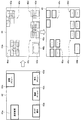
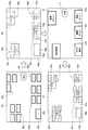
図5は、本実施形態による第1の画面表示例について説明するための遷移図である。図5に示すように、表示制御部17は、まず、出力先の表示領域であるタブレット端末2の表示部25に、表示画面42を表示するよう制御する。表示画面42は、現在表示画面であるデジタルカメラ1のメニュー画面30(図1参照)が拡大表示されたものである。
FIG. 5 is a transition diagram for explaining a first screen display example according to the present embodiment. As shown in FIG. 5, the
次いで、表示制御部17は、図5の表示画面44に示すように、各メニュー項目43a〜43eの表示を徐々に薄くしてフェードアウトさせると共に、新たなメニュー機能を示すアイコンを徐々に出現させるアニメーションを表示する。新たなアイコンは、各メニュー項目43a〜43eの次階層の機能を示すものである。なお、次階層がないメニュー項目(例えばメニュー項目43b)については、図5の表示画面44に示すように、当該メニュー項目の大きさが調整されて、他の新たなアイコンと同様の大きさのアイコンで表示される。
Next, as shown in the
そして、表示制御部17は、図5に示すように、新たに出現したアイコン群46a、46c、46d、46e、及びアイコン46bを含むメニュー画面(表示画面)45を表示させる。
Then, as shown in FIG. 5, the
このように、本実施形態では、表示態様の変更による画面の変化をアニメーションで示すことで、変更後の画面に含まれる増加したアイコンがどのメニュー項目と関連するものであるのかを示すことができる。 As described above, in this embodiment, it is possible to indicate which menu item is associated with the increased icon included in the screen after the change by displaying the change of the screen due to the change of the display mode with an animation. .
<3−2.第2の画面表示例>
上述した第1の画面表示例では、各メニュー項目43a〜43eが同時にフェードアウトし、各メニュー項目の次階層の機能を示すアイコンが同時に出現するアニメーションを示したが、本実施形態による画面の変化を表すアニメーションはこれに限定されない。例えば、本実施形態による表示制御部17は、各メニュー項目43a〜43eが順次フェードアウトして次階層の機能を示すアイコンが出現するアニメーションを示してもよい。以下、メニュー項目43a〜43eが順次変化する様子を表すアニメーションについて図6を参照して具体的に説明する。
<3-2. Second screen display example>
In the above-described first screen display example, the
図6は、本実施形態による第2の画面表示例について説明するための遷移図である。図6に示すように、表示制御部17は、出力先の表示領域であるタブレット端末2の表示部25に表示させた表示画面に含まれる各メニュー項目の表示態様を順次変化させていく。より具体的には、例えば表示制御部17は、まず表示画面47に含まれるメニュー項目43aをフェードアウトし、メニュー項目43aの次階層の機能を示すアイコン群46aを出現させるよう表示制御する。
FIG. 6 is a transition diagram for explaining a second screen display example according to the present embodiment. As shown in FIG. 6, the
次いで、表示制御部17は、図6の表示画面48に示すように、メニュー項目43bの表示態様を変化させる。ここでメニュー項目43bは次階層がない項目であるので、表示制御部17は、当該メニュー項目の大きさを調整し、他の新たに出現するアイコンと同様の大きさのアイコン46bに変更するよう制御する。
Next, the
次に、表示制御部17は、図6の表示画面49に示すように、メニュー項目43cをフェードアウトし、メニュー項目43cの次階層の機能を示すアイコン群46cを出現させるよう表示制御する。続いて、表示制御部17は、同様にメニュー項目43dの表示態様も変更する。
Next, as shown in the
そして、最後に、表示制御部17は、図6の表示画面50に示すように、メニュー項目43eをフェードアウトし、メニュー項目43eの次階層の機能を示すアイコン群46eを出現させるよう表示制御する。
Finally, as shown in the
このように、本実施形態では、順次メニュー項目の表示態様を変化させていくことで、変更後の画面に含まれる増加したアイコンがどのメニュー項目と関連するものであるのかをより明確に示すことができる。 As described above, in the present embodiment, by sequentially changing the display mode of the menu items, it is possible to more clearly indicate which menu item is associated with the increased icon included in the changed screen. Can do.
<3−3.第3の画面表示例>
以上説明した第1、第2の画面表示例では、画面変化の経過を示すアニメーションを表示することで、変更後の画面に含まれる増加したアイコンがどのメニュー項目と関連するのかを示しているが、本実施形態による関連性の明示方法はこれに限定されない。例えば、本実施形態では、変更後の画面に含まれる増加したアイコンと、変更前のメニュー項目との関連をオブジェクトの形の統一で明示してもよい。以下、図7を参照して具体的に説明する。
<3-3. Third screen display example>
In the first and second screen display examples described above, the animation indicating the progress of the screen change is displayed to indicate which menu item is associated with the increased icon included in the changed screen. The relevance indication method according to the present embodiment is not limited to this. For example, in the present embodiment, the association between the increased icon included in the screen after the change and the menu item before the change may be specified by unifying the object shape. Hereinafter, a specific description will be given with reference to FIG.
図7は、本実施形態による第3の画面表示例について説明するための図である。図7に示すように、デジタルカメラ1側で表示されているメニュー画面33(現在表示画面)に含まれるメニュー項目34a〜34eは、各々異なる形状で示されている。この場合、表示制御部17は、当該メニュー画面33をタブレット端末2側に出力する際、各メニュー項目34の表示態様を、各メニュー項目34の次階層の機能を示すアイコンであって、かつ、関連する各メニュー項目34と同様の形状を有するアイコンに変更する。
FIG. 7 is a diagram for explaining a third screen display example according to the present embodiment. As shown in FIG. 7, the
したがって、タブレット端末2側では、図7に示すように、メニュー画面51において、各々関連する各メニュー項目34a〜34eと同様の形状で示されるアイコン群52a、52c、52d、52e、及びアイコン52bが示される。
Therefore, on the
このように、本実施形態では、変更後の画面に含まれる増加したアイコンと変更前のメニュー項目との関連を、オブジェクトの形を統一することで明示することができる。 As described above, in this embodiment, the association between the increased icons included in the screen after the change and the menu item before the change can be specified by unifying the shape of the object.
<3−4.第4の画面表示例>
上記第3の画面表示例では、変更後の画面に含まれる増加したアイコンと、変更前のメニュー項目との関連をオブジェクトの形の統一で明示したが、本実施形態はこれに限定されず、例えばオブジェクトの色の統一で明示してもよい。以下、図8を参照して具体的に説明する。
<3-4. Fourth screen display example>
In the third screen display example, the relationship between the increased icon included in the screen after the change and the menu item before the change is clearly shown by unifying the shape of the object, but this embodiment is not limited to this, For example, the object color may be clearly specified. Hereinafter, a specific description will be given with reference to FIG.
図8は、本実施形態による第4の画面表示例について説明するための図である。図8に示すように、デジタルカメラ1側で表示されているメニュー画面36(現在表示画面)に含まれるメニュー項目37a〜37eは、各々異なる色で示されている。この場合、表示制御部17は、当該メニュー画面36をタブレット端末2側に出力する際、各メニュー項目37の表示態様を、各メニュー項目37の次階層の機能を示すアイコンであって、かつ、関連する各メニュー項目37と同様の色のアイコンに変更する。
FIG. 8 is a diagram for explaining a fourth screen display example according to the present embodiment. As shown in FIG. 8,
したがって、タブレット端末2側では、図8に示すように、メニュー画面54において、各々関連する各メニュー項目37a〜37eと同様の色で示されるアイコン群55a、55c、55d、55e、及びアイコン55bが示される。
Therefore, on the
このように、本実施形態では、変更後の画面に含まれる増加したアイコンと変更前のメニュー項目との関連を、オブジェクトの色を統一することで明示することができる。なお、本実施形態では、色の統一の他、模様の統一により関連性を明示してもよい。 Thus, in this embodiment, the association between the increased icons included in the screen after the change and the menu item before the change can be clearly shown by unifying the colors of the objects. In the present embodiment, the relevance may be specified by unifying the patterns as well as unifying the colors.
<3−5.第5の画面表示例>
上述した第1〜第4の画面表示例では、現在表示画面の領域よりも出力先表示領域の方が大きい場合、複数階層の機能を初期画面に含む表示態様に変更、すなわちメニュー機能を示すアイコン(メニュー項目)の数を増やすことで初期画面の情報量を増加させていた。しかしながら、本実施形態による初期画面の情報量を増加させる方法は、上述したようなアイコンの数を増やす方法に限定されない。
<3-5. Fifth screen display example>
In the above-described first to fourth screen display examples, when the output destination display area is larger than the area of the current display screen, the display mode is changed to a display mode including a function of a plurality of layers, that is, an icon indicating a menu function The amount of information on the initial screen was increased by increasing the number of (menu items). However, the method for increasing the amount of information on the initial screen according to the present embodiment is not limited to the method for increasing the number of icons as described above.
例えば、画面に表示される各メニュー項目(アイコン)の画像を、次階層の機能を示すアイテムの表示を含む画像に変更してもよい。このように、各アイコンの画像に次階層の機能の表示を含むことで、アイコンの数を変更せずとも情報の詳細度合いを高めることができ、ユーザは、どのメニュー項目を選択すれば意図する機能にたどり着くことができるのか容易に把握することができる。以下、図9を参照して具体的に説明する。 For example, the image of each menu item (icon) displayed on the screen may be changed to an image including a display of an item indicating the function of the next layer. Thus, by including the display of the function of the next layer in the image of each icon, the degree of detail of information can be increased without changing the number of icons, and the user intends which menu item to select. You can easily figure out if you can get to the function. Hereinafter, a specific description will be given with reference to FIG.
図9は、本実施形態による第5の画面表示例について説明するための図である。図9に示すように、デジタルカメラ1側で表示されているメニュー画面30(現在表示画面)を、タブレット端末2側に出力する際、表示制御部17は、各メニュー項目31a〜31eの表示態様を、より詳細な情報を示す(より情報量が多い)表示態様に変更する。具体的には、図9のメニュー画面57に示すように、次階層の機能を示すアイテムの表示59a、59c、59d、59eを各々含むアイコン58a、58c、58d、58eの表示態様に変更する。
FIG. 9 is a diagram for explaining a fifth screen display example according to the present embodiment. As shown in FIG. 9, when the menu screen 30 (current display screen) displayed on the
このように、本実施形態では、変更後の画面に含まれるアイコンの数は変更前と変化しないが、アイコンの表示態様を次階層の機能を示すアイテムの表示を含む表示態様に変更することで、より詳細な情報を示すことができる。また、各アイコンと、各アイコンを選択した場合に表示される次階層の表示画面で選択可能な機能を明示することで、ユーザは、どのアイコンを選択すれば意図する機能にたどり着くことができるのか容易に把握することができる。 As described above, in this embodiment, the number of icons included in the screen after the change is not changed from that before the change, but the icon display mode is changed to a display mode including display of items indicating functions of the next hierarchy. More detailed information can be shown. In addition, by specifying each icon and the functions that can be selected on the display screen of the next layer displayed when each icon is selected, the user can reach the intended function by selecting which icon. It can be easily grasped.
<3−6.第6の画面表示例>
上述した第1の画面表示例では、図5に示すように、情報の詳細度合いが高い表示態様に変更されたアイコン群46a等は、関連する変更前のメニュー項目43a等の表示位置とそれぞれ対応する位置に配置されている。これにより、ユーザは、変更後のアイコン群と変更前のメニュー項目との関連を直感的に把握することができる。しかしながら、変更後のメニュー画面に含まれるアイコンが多い場合、どのアイコンがどの位置に配置されたアイコン群に属するのか不明瞭になってしまう。そこで、本実施形態では、ユーザ操作に応じて、指定されたアイコンが属するアイコン群の配置位置を示す表示制御を行うことで、変更後のアイコン群と変更前のメニュー項目との関連を明示することができる。以下、図10を参照して具体的に説明する。
<3-6. Sixth screen display example>
In the first screen display example described above, as shown in FIG. 5, the
図10は、本実施形態による第6の画面表示例について説明するための遷移図である。図10に示すように、デジタルカメラ1からタブレット端末2に出力されたメニュー画面60は、情報の詳細度合いが高い表示態様に変更されており、アイコン群61a、61c、61d、61e及びアイコン61bを含んでいる。また、各アイコン群61a等は、図10に示すように、輪郭がぼかし処理されている。
FIG. 10 is a transition diagram for explaining a sixth screen display example according to the present embodiment. As shown in FIG. 10, the
ここで、メニュー画面60に含まれるアイコン610が、アイコン群61aとアイコン群61cのいずれのアイコン群に属するかが明確ではない。この場合、ユーザは、デジタルカメラ1の操作入力部14を操作し、メニュー画面上に表示されるカーソル(不図示)をアイコン610に移動させる。かかるユーザ操作に応じて、表示制御部17は、図10のメニュー画面63に示すように、アイコン610が属するアイコン群61cの輪郭を強調するよう表示制御する。これにより、ユーザは、アイコン610が画面下中央に配置されたアイコン群61cに属することが分かり、また、変更前の画面下中央に配置されていたメニュー項目(例えば図1のメニュー項目31c)と関連するものであることを把握することができる。
Here, it is not clear whether the
このように、本実施形態では、変更後の画面に含まれる各アイコン群61a等の輪郭をぼかして表示し、ユーザに指定されたアイコンが属するアイコン群の輪郭を強調表示することで、どのアイコンがどのアイコン群に属するかを明示することができる。なお、図10に示す例では、ぼかし及び輪郭強調を用いて、どのアイコンがどのアイコン群に属するかを明示しているが、本実施形態による明示方法はこれに限定されない。例えば、表示制御部17は、指定されたアイコンが属するアイコン群のみを揺らすなど、アイコン群を動かすよう表示制御することで明示してもよい。
As described above, in the present embodiment, the outline of each
<3−7.第7の画面表示例>
上述した第1、第2の画面表示例では、表示画面が出力される際に、画面変化の経過を示すアニメーションが表示されるが、本実施形態によるアニメーション表示のタイミングはこれに限定されず、例えばユーザ操作をトリガとして表示してもよい。以下、図11を参照して具体的に説明する。
<3-7. Seventh screen display example>
In the first and second screen display examples described above, when the display screen is output, an animation indicating the progress of the screen change is displayed. However, the timing of the animation display according to the present embodiment is not limited to this, For example, a user operation may be displayed as a trigger. Hereinafter, a specific description will be given with reference to FIG.
図11は、本実施形態による第7の画面表示例について説明するための遷移図である。図11に示すように、例えばタブレット端末2に出力され、情報の詳細度合いが高い表示態様に変更されたメニュー画面65には、アイコン群46a、46c、46d、46e、及びアイコン46bに加えて、結合ボタン66が含まれる。
FIG. 11 is a transition diagram for explaining a seventh screen display example according to the present embodiment. As shown in FIG. 11, in addition to the
ユーザ操作により結合ボタン66が選択されると、表示制御部17は、メニュー画面65に含まれる各オブジェクト(アイコン群46a等)の表示態様を情報の詳細度合いが低い表示態様に戻す際の画面変化の経過を示すアニメーションを表示する。具体的には、表示制御部17は、図11のメニュー画面68に示すように、アイコン群46a、46c、46d、46eを徐々に小さくすると共に、メニュー項目43a、43c、43d、43eをフェードインさせる。メニュー項目43a、43c、43d、43eは、それぞれアイコン群46a、46c、46d、46eの上層の機能を示すものである。なお、アイコン46bは単層であるので、表示制御部17は、アイコン46bの大きさを調整し、他のメニュー項目43a等と同様の大きさに変化させる。以下、このように大きさを変化させたアイコン46bをメニュー項目43bと称す。
When the
そして、図11に示すように、画面変化の経過を示すアニメーション(メニュー画面65)が表示された後、情報の詳細度合いが低い(アイコン数が少ない)表示態様に変更されたメニュー画面70が表示される。
Then, as shown in FIG. 11, after an animation (menu screen 65) showing the progress of the screen change is displayed, the
このように、ユーザ操作をトリガとして、画面変化の経過を示すアニメーションを表示し、元の表示態様に戻すことで、増加したアイコンがどのメニュー項目と関連するものであるのかを明確に示すことができる。 In this way, it is possible to clearly indicate which menu item is associated with the increased icon by displaying the animation indicating the progress of the screen change triggered by the user operation and returning to the original display mode. it can.
なお、図11に示すように、メニュー画面70には、メニュー項目43a、43b、43c、43d、43eに加えて、分解ボタン71が含まれる。分解ボタン71は、情報の詳細度合いが高い表示態様であるメニュー画面65に戻すための操作ボタンである。
As shown in FIG. 11, the
表示制御部17は、ユーザ操作により分解ボタン71が選択されると、メニュー画面70に含まれる各オブジェクト(メニュー項目43a〜43e)の表示態様を情報の詳細度合いが高い表示態様に変更する際の画面変化の経過を示すアニメーションを表示する。具体的には、表示制御部17は、図11のメニュー画面72に示すように、各メニュー項目43a〜43eの表示を徐々に薄くしてフェードアウトさせると共に、アイコン群46a、46c、46d、46e及びアイコン46bを徐々に出現させるアニメーションを表示する。
When the
このように、表示制御部17は、情報の詳細度合いが低い表示態様に戻した表示画面を、ユーザ操作をトリガとして、情報の詳細度合いが高い表示態様に再び変更することも可能である。また、この際も、画面変化の経過を表すアニメーションが表示されることで、ユーザは、表示態様変更前の各メニュー項目と、変更後の増加したアイコンとの関連を直感的に把握することができる。
In this way, the
(補足)
以上、本実施形態による画面表示例について、第1〜第7の画面表示例を用いて具体的に説明した。なお、本実施形態による画面表示例は、上述した各画面表示例を適宜組み合わせたものであってもよい。
(Supplement)
Heretofore, the screen display examples according to the present embodiment have been specifically described using the first to seventh screen display examples. Note that the screen display examples according to the present embodiment may be appropriately combined with the above-described screen display examples.
例えば、表示制御部17は、第1または第2の表示画面例で説明した画面変化の経過を表すアニメーションの表示を、第3〜第6の表示画面例においてタブレット端末2側に画面出力する際に適用してもよい。また、第3及び第4の表示画面例を組み合わせて、変更後の画面に含まれる増加したアイコンと変更前のメニュー項目との関連を、オブジェクトの形及び色を統一することで明示してもよい。
For example, when the
<<4.まとめ>>
上述したように、本実施形態による表示制御では、出力先の表示領域に応じて、出力する表示画面に含まれる各オブジェクトを、現在表示画面に含まれる各オブジェクトの表示態様と情報の詳細度合いにおいて異なる表示態様に変更する。具体的には、例えば出力先の表示領域が現在表示画面の表示領域より大きい場合、出力する表示画面に含まれる各オブジェクトを、情報の詳細度合いが高い表示態様に変更することで、大きい表示領域をより効果的に利用することができる。情報の詳細度合いが高い表示態様とは、1のアイコン(メニュー項目)を次階層の機能を示す複数のアイコンに分解してアイコン数を増加させる態様であってもよい。また、情報の詳細度合いが高い表示態様とは、1のアイコン(メニュー項目)を次階層の機能を示す複数のアイテムの表示を含む1のアイコンに変更し、アイコン数は増減させない表示態様であってもよい。
<< 4. Summary >>
As described above, in the display control according to the present embodiment, each object included in the output display screen is changed according to the display mode of each object included in the current display screen and the degree of detail of information according to the display area of the output destination. Change to a different display mode. Specifically, for example, when the display area of the output destination is larger than the display area of the current display screen, a large display area can be obtained by changing each object included in the output display screen to a display mode with a high degree of detail of information. Can be used more effectively. The display mode in which the degree of detail of information is high may be a mode in which one icon (menu item) is decomposed into a plurality of icons indicating functions of the next layer to increase the number of icons. In addition, a display mode in which the degree of detail of information is high is a display mode in which one icon (menu item) is changed to one icon including display of a plurality of items indicating functions of the next hierarchy, and the number of icons is not increased or decreased. May be.
また、本実施形態では、表示態様の変更による画面の変化をアニメーションで示すことで、表示態様変更後に増加したアイコンが、表示態様変更前のどのメニュー項目と関連するものであるのかを明示することも可能である。 In the present embodiment, the screen change caused by the change of the display mode is indicated by an animation, and the menu item before the change of the display mode is clearly associated with the menu item before the display mode is changed. Is also possible.
以上、添付図面を参照しながら本開示の好適な実施形態について詳細に説明したが、本技術はかかる例に限定されない。本開示の技術分野における通常の知識を有する者であれば、特許請求の範囲に記載された技術的思想の範疇内において、各種の変更例または修正例に想到し得ることは明らかであり、これらについても、当然に本開示の技術的範囲に属するものと了解される。 The preferred embodiments of the present disclosure have been described in detail above with reference to the accompanying drawings, but the present technology is not limited to such examples. It is obvious that a person having ordinary knowledge in the technical field of the present disclosure can come up with various changes or modifications within the scope of the technical idea described in the claims. Of course, it is understood that it belongs to the technical scope of the present disclosure.
なお、本技術は以下のような構成も取ることができる。
(1)
外部に表示画面を出力する出力部と、
前記外部に出力する表示画面に含まれるオブジェクトを、現在表示画面に含まれる同オブジェクトの第1の表示態様と情報の詳細度合いにおいて異なる第2の表示態様に変更するよう制御する表示制御部と、
を備える、表示制御装置。
(2)
前記表示制御装置は、
出力先の表示領域の大きさと前記現在表示画面の大きさとを比較する比較部をさらに備え、
前記表示制御部は、比較の結果、前記出力先の表示領域が前記現在表示画面の領域より大きい場合、前記外部に出力する表示画面に含まれるオブジェクトを、前記現在表示画面に含まれる同オブジェクトより情報の詳細度合いが高い前記第2の表示態様に変更する、前記(1)に記載の表示制御装置。
(3)
前記第2の表示態様のオブジェクトは、前記現在表示画面に含まれる同オブジェクトの次階層の機能を示す1以上のアイテムの表示を含む1のアイコンで表示される、前記(2)に記載の表示制御装置。
(4)
前記第2の表示態様のオブジェクトは、前記現在表示画面に含まれる同オブジェクトの次階層の機能を示す1以上のアイコンで表示される、前記(2)に記載の表示制御装置。
(5)
前記表示制御部は、前記外部に出力する表示画面における前記オブジェクトの表示位置を、前記現在表示画面における同オブジェクトの表示位置と対応するよう表示制御する、前記(1)〜(4)のいずれか1項に記載の表示制御装置。
(6)
前記表示制御部は、前記外部に出力する表示画面における前記オブジェクトが、前記第1の表示態様から前記第2の表示態様に変化する際の遷移画面を表示するよう制御する、前記(1)〜(5)のいずれか1項に記載の表示制御装置。
(7)
前記表示制御部は、複数の前記オブジェクト毎に、前記遷移画面を順次表示するよう制御する、前記(6)に記載の表示制御装置。
(8)
前記表示制御部は、前記外部に出力する表示画面における前記オブジェクトの色または形状を、前記現在表示画面における同オブジェクトの色または形状と対応するよう制御する、前記(1)〜(7)のいずれか1項に記載の表示制御装置。
(9)
前記表示制御部は、前記外部に出力する表示画面において、ユーザに指定されたアイコンが属するアイコン群を輪郭の強調または動きの同期制御により明示する表示制御を行う、前記(1)〜(8)のいずれか1項に記載の表示制御装置。
(10)
前記表示制御部は、前記外部に出力する表示画面において前記第2の表示態様で表示されるオブジェクトを、ユーザ操作に応じて前記第1の表示態様による表示に戻す表示制御を行う、前記(1)〜(9)のいずれか1項に記載の表示制御装置。
(11)
前記表示制御装置は、
出力先の表示領域の大きさと前記現在表示画面の大きさとを比較する比較部をさらに備え、
前記表示制御部は、比較の結果、前記出力先の表示領域が前記現在表示画面の領域より小さい場合、前記外部に出力する表示画面に含まれるオブジェクトを、前記現在表示画面の対応する同オブジェクトより情報の詳細度合いが低い前記第2の表示態様に変更する、前記(1)に記載の表示制御装置。
(12)
外部に出力する表示画面に含まれるオブジェクトを、現在表示画面に含まれる同オブジェクトの第1の表示態様と情報の詳細度合いにおいて異なる第2の表示態様に変更するステップと、
前記第2の表示態様に変更したオブジェクトを含む表示画面を外部に出力するステップと、
を含む、表示制御方法。
(13)
コンピュータに、
外部に表示画面を出力する出力部と、
前記外部に出力する表示画面に含まれるオブジェクトを、現在表示画面に含まれる同オブジェクトの第1の表示態様と情報の詳細度合いにおいて異なる第2の表示態様に変更するよう制御する表示制御部と、
として機能させるための、プログラム。
In addition, this technique can also take the following structures.
(1)
An output unit for outputting a display screen to the outside;
A display control unit for controlling the object included in the display screen to be output to the outside to be changed to a second display mode different from the first display mode of the same object included in the current display screen in the degree of detail of information;
A display control device.
(2)
The display control device includes:
A comparison unit that compares the size of the display area of the output destination with the size of the current display screen;
When the display area of the output destination is larger than the area of the current display screen as a result of the comparison, the display control unit may change an object included in the display screen to be output to the outside from the same object included in the current display screen. The display control apparatus according to (1), wherein the display mode is changed to the second display mode in which the degree of detail of information is high.
(3)
The display according to (2), wherein the object in the second display mode is displayed with one icon including a display of one or more items indicating a function of a next layer of the object included in the current display screen. Control device.
(4)
The display control apparatus according to (2), wherein the object in the second display mode is displayed with one or more icons indicating functions of a next layer of the object included in the current display screen.
(5)
The display control unit performs display control so that the display position of the object on the display screen output to the outside corresponds to the display position of the object on the current display screen. The display control apparatus according to
(6)
The display control unit controls to display a transition screen when the object on the display screen output to the outside changes from the first display mode to the second display mode. The display control apparatus according to any one of (5).
(7)
The display control device according to (6), wherein the display control unit controls to sequentially display the transition screen for each of the plurality of objects.
(8)
The display control unit controls the color or shape of the object on the display screen output to the outside so as to correspond to the color or shape of the object on the current display screen, any one of (1) to (7) The display control apparatus according to
(9)
The display control unit performs display control in which an icon group to which an icon designated by the user belongs is clearly specified by outline emphasis or movement synchronization control on the display screen to be output to the outside (1) to (8). The display control apparatus according to any one of the above.
(10)
The display control unit performs display control to return an object displayed in the second display mode on the display screen output to the outside to display in the first display mode in response to a user operation. The display control apparatus according to any one of (9) to (9).
(11)
The display control device includes:
A comparison unit that compares the size of the display area of the output destination with the size of the current display screen;
If the display area of the output destination is smaller than the area of the current display screen as a result of the comparison, the display control unit causes the object included in the display screen to be output to the outside from the corresponding object of the current display screen. The display control apparatus according to (1), wherein the display mode is changed to the second display mode in which the degree of detail of information is low.
(12)
Changing the object included in the display screen to be output to the outside to a second display mode that differs from the first display mode of the same object included in the current display screen in the degree of detail of information;
Outputting a display screen including the object changed to the second display mode to the outside;
Including a display control method.
(13)
On the computer,
An output unit for outputting a display screen to the outside;
A display control unit for controlling the object included in the display screen to be output to the outside to be changed to a second display mode different from the first display mode of the same object included in the current display screen in the degree of detail of information;
Program to function as
1 デジタルカメラ
10 CPU
11 ROM
12 RAM
13 カメラモジュール
14 操作入力部
16 記憶メディア
17 表示制御部
18 比較部
19 表示部
20 外部I/F
2 タブレット端末
25 表示部
30、33、36、45、51、54、57、65、68、70、72 メニュー画面
31a〜31e、34a〜34e、37a〜37e、43a〜43e メニュー項目
46a、46c〜46e、52a、52c〜52e、55a、55c〜55e、61a、61c〜61e アイコン群
46b、52b、55b、58a〜58e、61b、610 アイコン
66 結合ボタン
71 分解ボタン
1
11 ROM
12 RAM
13
2
66
Claims (13)
前記外部に出力する表示画面に含まれるオブジェクトを、現在表示画面に含まれる同オブジェクトの第1の表示態様と情報の詳細度合いにおいて異なる第2の表示態様に変更するよう制御する表示制御部と、
を備え、
前記表示制御部は、前記外部に出力する表示画面において、詳細度合いが変化しないオブジェクトの表示サイズを、詳細度合いが変化した第2の表示態様で表示されたオブジェクトの表示サイズに応じて変化させるよう制御する、表示制御装置。 An output control unit for controlling the output of the display screen to the outside;
A display control unit for controlling the object included in the display screen to be output to the outside to be changed to a second display mode different from the first display mode of the same object included in the current display screen in the degree of detail of information;
Equipped with a,
The display control unit changes the display size of the object whose detail level does not change on the display screen output to the outside according to the display size of the object displayed in the second display mode whose detail level has changed. control to display control device.
出力先の表示領域の大きさと前記現在表示画面の大きさとを比較する比較部をさらに備え、
前記表示制御部は、比較の結果、前記出力先の表示領域が前記現在表示画面の領域より大きい場合、前記外部に出力する表示画面に含まれるオブジェクトを、前記現在表示画面に含まれる同オブジェクトより情報の詳細度合いが高い前記第2の表示態様に変更する、請求項1に記載の表示制御装置。 The display control device includes:
A comparison unit that compares the size of the display area of the output destination with the size of the current display screen;
When the display area of the output destination is larger than the area of the current display screen as a result of the comparison, the display control unit may change an object included in the display screen to be output to the outside from the same object included in the current display screen. The display control apparatus according to claim 1, wherein the display mode is changed to the second display mode in which the degree of detail of information is high.
出力先の表示領域の大きさと前記現在表示画面の大きさとを比較する比較部をさらに備え、
前記表示制御部は、比較の結果、前記出力先の表示領域が前記現在表示画面の領域より小さい場合、前記外部に出力する表示画面に含まれるオブジェクトを、前記現在表示画面の対応する同オブジェクトより情報の詳細度合いが低い前記第2の表示態様に変更する、請求項1に記載の表示制御装置。 The display control device includes:
A comparison unit that compares the size of the display area of the output destination with the size of the current display screen;
If the display area of the output destination is smaller than the area of the current display screen as a result of the comparison, the display control unit causes the object included in the display screen to be output to the outside from the corresponding object of the current display screen. The display control apparatus according to claim 1, wherein the display control device is changed to the second display mode in which the degree of detail of information is low.
前記外部に出力する表示画面において、詳細度合いが変化しないオブジェクトの表示サイズを、詳細度合いが変化した第2の表示態様で表示されたオブジェクトの表示サイズに応じて変化させるよう制御するステップと、
前記第2の表示態様に変更したオブジェクトを含む表示画面を外部に出力するよう制御するステップと、
を含む表示制御方法。 Changing the object included in the display screen to be output to the outside to a second display mode that differs from the first display mode of the same object included in the current display screen in the degree of detail of information;
Controlling the display size of the object whose detail level does not change on the display screen to be output to the outside according to the display size of the object displayed in the second display mode whose detail level has changed;
Controlling to output the display screen including the object changed to the second display mode to the outside;
A display control method including:
外部への表示画面の出力を制御する出力制御部と、
前記外部に出力する表示画面に含まれるオブジェクトを、現在表示画面に含まれる同オブジェクトの第1の表示態様と情報の詳細度合いにおいて異なる第2の表示態様に変更するよう制御する表示制御部と、
として機能させ、
前記表示制御部は、前記外部に出力する表示画面において、詳細度合いが変化しないオブジェクトの表示サイズを、詳細度合いが変化した第2の表示態様で表示されたオブジェクトの表示サイズに応じて変化させるよう制御する、プログラム。 On the computer,
An output control unit for controlling the output of the display screen to the outside;
A display control unit for controlling the object included in the display screen to be output to the outside to be changed to a second display mode different from the first display mode of the same object included in the current display screen in the degree of detail of information;
To function as,
The display control unit changes the display size of the object whose detail level does not change on the display screen output to the outside according to the display size of the object displayed in the second display mode whose detail level has changed. A program to control .
Priority Applications (5)
| Application Number | Priority Date | Filing Date | Title |
|---|---|---|---|
| JP2012275539A JP5935682B2 (en) | 2012-12-18 | 2012-12-18 | Display control apparatus, display control method, and program |
| EP13791861.1A EP2936297A1 (en) | 2012-12-18 | 2013-10-24 | Display control device, display control method, and program |
| CN201380064185.6A CN104838351A (en) | 2012-12-18 | 2013-10-24 | Display control device, display control method, and program |
| PCT/JP2013/006318 WO2014097523A1 (en) | 2012-12-18 | 2013-10-24 | Display control device, display control method, and program |
| US14/646,111 US10120636B2 (en) | 2012-12-18 | 2013-10-24 | Display control device and display control method for displaying content on multiple display screens |
Applications Claiming Priority (1)
| Application Number | Priority Date | Filing Date | Title |
|---|---|---|---|
| JP2012275539A JP5935682B2 (en) | 2012-12-18 | 2012-12-18 | Display control apparatus, display control method, and program |
Publications (3)
| Publication Number | Publication Date |
|---|---|
| JP2014120036A JP2014120036A (en) | 2014-06-30 |
| JP2014120036A5 JP2014120036A5 (en) | 2015-03-19 |
| JP5935682B2 true JP5935682B2 (en) | 2016-06-15 |
Family
ID=49584761
Family Applications (1)
| Application Number | Title | Priority Date | Filing Date |
|---|---|---|---|
| JP2012275539A Active JP5935682B2 (en) | 2012-12-18 | 2012-12-18 | Display control apparatus, display control method, and program |
Country Status (5)
| Country | Link |
|---|---|
| US (1) | US10120636B2 (en) |
| EP (1) | EP2936297A1 (en) |
| JP (1) | JP5935682B2 (en) |
| CN (1) | CN104838351A (en) |
| WO (1) | WO2014097523A1 (en) |
Families Citing this family (5)
| Publication number | Priority date | Publication date | Assignee | Title |
|---|---|---|---|---|
| JP2016057731A (en) * | 2014-09-08 | 2016-04-21 | セイコーエプソン株式会社 | Electronic apparatus and display control program |
| CN108089790A (en) * | 2017-12-29 | 2018-05-29 | 上海爱优威软件开发有限公司 | A kind of termination function instantiated method and system |
| US11012750B2 (en) * | 2018-11-14 | 2021-05-18 | Rohde & Schwarz Gmbh & Co. Kg | Method for configuring a multiviewer as well as multiviewer |
| JP2020135518A (en) * | 2019-02-21 | 2020-08-31 | キヤノン株式会社 | Projection device and control method for the same |
| US11343583B2 (en) * | 2019-04-11 | 2022-05-24 | Hisense Visual Technology Co., Ltd. | Method for displaying GUI for providing menu items and display device |
Family Cites Families (8)
| Publication number | Priority date | Publication date | Assignee | Title |
|---|---|---|---|---|
| JP2000003241A (en) * | 1998-06-16 | 2000-01-07 | Minolta Co Ltd | Display device |
| JP2005335555A (en) * | 2004-05-27 | 2005-12-08 | Nissan Motor Co Ltd | Vehicle information presenting device and method |
| US7962854B2 (en) * | 2004-10-19 | 2011-06-14 | Sony Ericsson Mobile Communications Ab | Systems, methods and computer program products for displaying content on multiple display screens using handheld wireless communicators |
| WO2006043977A1 (en) * | 2004-10-19 | 2006-04-27 | Sony Ericsson Mobile Communications Ab | Handheld wireless communication device for displaying information on multiple display screens, method of operating the device, and computer program product for operating the device |
| JP4781186B2 (en) * | 2006-07-18 | 2011-09-28 | キヤノン株式会社 | User interface presentation apparatus and method |
| JP5113218B2 (en) * | 2010-06-17 | 2013-01-09 | パナソニック株式会社 | Portable terminal device, display control method, and display control program |
| JP5784944B2 (en) * | 2011-03-29 | 2015-09-24 | 京セラ株式会社 | Electronics |
| US9727301B2 (en) * | 2011-06-03 | 2017-08-08 | Apple Inc. | Gesture-based prioritization of graphical output on remote displays |
-
2012
- 2012-12-18 JP JP2012275539A patent/JP5935682B2/en active Active
-
2013
- 2013-10-24 WO PCT/JP2013/006318 patent/WO2014097523A1/en active Application Filing
- 2013-10-24 EP EP13791861.1A patent/EP2936297A1/en not_active Ceased
- 2013-10-24 US US14/646,111 patent/US10120636B2/en not_active Expired - Fee Related
- 2013-10-24 CN CN201380064185.6A patent/CN104838351A/en active Pending
Also Published As
| Publication number | Publication date |
|---|---|
| JP2014120036A (en) | 2014-06-30 |
| WO2014097523A1 (en) | 2014-06-26 |
| US10120636B2 (en) | 2018-11-06 |
| US20150301785A1 (en) | 2015-10-22 |
| CN104838351A (en) | 2015-08-12 |
| EP2936297A1 (en) | 2015-10-28 |
Similar Documents
| Publication | Publication Date | Title |
|---|---|---|
| US10809896B2 (en) | Display apparatus and control method thereof | |
| JP5935682B2 (en) | Display control apparatus, display control method, and program | |
| US8818274B2 (en) | Automatic interfacing between a master device and object device | |
| US9496005B2 (en) | Electronic apparatus, display control method and program for displaying an image for selecting a content item to be reproduced | |
| US9626076B2 (en) | Display apparatus for displaying images and method thereof | |
| US20170324898A9 (en) | Methods and apparatus for capturing a panoramic image | |
| CN106227439A (en) | For capturing digitally enhanced image and the equipment interacted and method | |
| CN105103535A (en) | Apparatus and method for positioning image area using image sensor location | |
| US10855911B2 (en) | Method for setting image capture conditions and electronic device performing the same | |
| US11423867B2 (en) | Signal processing device and image display apparatus including the same | |
| US11430195B2 (en) | Information processing apparatus, information processing method, and program for improving user-friendliness of an animated tutorial depicting assembling parts for creating a robot | |
| CN103986933A (en) | Dynamic picture displaying method and device | |
| US10090020B1 (en) | Content summarization | |
| WO2023093169A1 (en) | Photographing method and electronic device | |
| JP2014120036A5 (en) | ||
| KR102150905B1 (en) | Method for photographing based on WiFi Direct and electronic device performing thereof | |
| CN104603862B (en) | Strengthen the method for moving picture element | |
| US8793603B2 (en) | Image processing device, image processing method, and image processing program | |
| JP2010166417A (en) | Camera, display control unit for camera, display control method, and program for display control | |
| JP6742789B2 (en) | Display control device, control method thereof, program, and storage medium | |
| JP6262927B1 (en) | Information processing apparatus, information processing method, program, and storage medium | |
| JP2010166418A (en) | Camera, display control device for camera, display control method, and program for display control | |
| JP2016062267A (en) | Apparatus and method for display processing | |
| JP6481304B2 (en) | Display processing apparatus and display processing method | |
| JP2008242991A (en) | Image display device and program |
Legal Events
| Date | Code | Title | Description |
|---|---|---|---|
| A521 | Request for written amendment filed |
Free format text: JAPANESE INTERMEDIATE CODE: A523 Effective date: 20150203 |
|
| A621 | Written request for application examination |
Free format text: JAPANESE INTERMEDIATE CODE: A621 Effective date: 20150203 |
|
| A131 | Notification of reasons for refusal |
Free format text: JAPANESE INTERMEDIATE CODE: A131 Effective date: 20151201 |
|
| A521 | Request for written amendment filed |
Free format text: JAPANESE INTERMEDIATE CODE: A523 Effective date: 20160122 |
|
| TRDD | Decision of grant or rejection written | ||
| A01 | Written decision to grant a patent or to grant a registration (utility model) |
Free format text: JAPANESE INTERMEDIATE CODE: A01 Effective date: 20160412 |
|
| A61 | First payment of annual fees (during grant procedure) |
Free format text: JAPANESE INTERMEDIATE CODE: A61 Effective date: 20160425 |
|
| R151 | Written notification of patent or utility model registration |
Ref document number: 5935682 Country of ref document: JP Free format text: JAPANESE INTERMEDIATE CODE: R151 |
|
| R250 | Receipt of annual fees |
Free format text: JAPANESE INTERMEDIATE CODE: R250 |
|
| R250 | Receipt of annual fees |
Free format text: JAPANESE INTERMEDIATE CODE: R250 |