JP5935272B2 - Biological signal measuring device - Google Patents
Biological signal measuring device Download PDFInfo
- Publication number
- JP5935272B2 JP5935272B2 JP2011205582A JP2011205582A JP5935272B2 JP 5935272 B2 JP5935272 B2 JP 5935272B2 JP 2011205582 A JP2011205582 A JP 2011205582A JP 2011205582 A JP2011205582 A JP 2011205582A JP 5935272 B2 JP5935272 B2 JP 5935272B2
- Authority
- JP
- Japan
- Prior art keywords
- resistance value
- biological signal
- electrode
- resistor
- measurement
- Prior art date
- Legal status (The legal status is an assumption and is not a legal conclusion. Google has not performed a legal analysis and makes no representation as to the accuracy of the status listed.)
- Expired - Fee Related
Links
- 238000005259 measurement Methods 0.000 claims description 78
- 230000007935 neutral effect Effects 0.000 description 18
- 210000003128 head Anatomy 0.000 description 16
- 238000001514 detection method Methods 0.000 description 15
- 238000010586 diagram Methods 0.000 description 8
- 238000005516 engineering process Methods 0.000 description 7
- 210000004556 brain Anatomy 0.000 description 6
- 230000003321 amplification Effects 0.000 description 5
- 238000003199 nucleic acid amplification method Methods 0.000 description 5
- 238000000034 method Methods 0.000 description 4
- 241001465754 Metazoa Species 0.000 description 2
- 210000000577 adipose tissue Anatomy 0.000 description 2
- 210000000624 ear auricle Anatomy 0.000 description 2
- 102000003712 Complement factor B Human genes 0.000 description 1
- 108090000056 Complement factor B Proteins 0.000 description 1
- 238000004891 communication Methods 0.000 description 1
- 239000007788 liquid Substances 0.000 description 1
- 230000036403 neuro physiology Effects 0.000 description 1
- 230000001131 transforming effect Effects 0.000 description 1
Images


Classifications
-
- A—HUMAN NECESSITIES
- A61—MEDICAL OR VETERINARY SCIENCE; HYGIENE
- A61B—DIAGNOSIS; SURGERY; IDENTIFICATION
- A61B5/00—Measuring for diagnostic purposes; Identification of persons
- A61B5/24—Detecting, measuring or recording bioelectric or biomagnetic signals of the body or parts thereof
- A61B5/316—Modalities, i.e. specific diagnostic methods
- A61B5/369—Electroencephalography [EEG]
-
- A—HUMAN NECESSITIES
- A61—MEDICAL OR VETERINARY SCIENCE; HYGIENE
- A61B—DIAGNOSIS; SURGERY; IDENTIFICATION
- A61B5/00—Measuring for diagnostic purposes; Identification of persons
- A61B5/68—Arrangements of detecting, measuring or recording means, e.g. sensors, in relation to patient
- A61B5/6801—Arrangements of detecting, measuring or recording means, e.g. sensors, in relation to patient specially adapted to be attached to or worn on the body surface
- A61B5/6813—Specially adapted to be attached to a specific body part
- A61B5/6814—Head
-
- A—HUMAN NECESSITIES
- A61—MEDICAL OR VETERINARY SCIENCE; HYGIENE
- A61B—DIAGNOSIS; SURGERY; IDENTIFICATION
- A61B5/00—Measuring for diagnostic purposes; Identification of persons
- A61B5/02—Detecting, measuring or recording pulse, heart rate, blood pressure or blood flow; Combined pulse/heart-rate/blood pressure determination; Evaluating a cardiovascular condition not otherwise provided for, e.g. using combinations of techniques provided for in this group with electrocardiography or electroauscultation; Heart catheters for measuring blood pressure
- A61B5/024—Detecting, measuring or recording pulse rate or heart rate
-
- A—HUMAN NECESSITIES
- A61—MEDICAL OR VETERINARY SCIENCE; HYGIENE
- A61B—DIAGNOSIS; SURGERY; IDENTIFICATION
- A61B5/00—Measuring for diagnostic purposes; Identification of persons
- A61B5/24—Detecting, measuring or recording bioelectric or biomagnetic signals of the body or parts thereof
- A61B5/316—Modalities, i.e. specific diagnostic methods
- A61B5/318—Heart-related electrical modalities, e.g. electrocardiography [ECG]
Description
本技術は、脳波や心電図等の生体信号を測定するための生体信号測定装置に関する。 The present technology relates to a biological signal measuring apparatus for measuring biological signals such as brain waves and electrocardiograms.
脳波、筋電図、心電図、体脂肪率等、生体(ヒトを含む動物)に電極を接触させて電位信号(以下、生体信号)を測定する生体信号測定装置において、電極と生体表面の間には接触抵抗が存在する。 In a biological signal measuring apparatus that measures an electric potential signal (hereinafter referred to as a biological signal) by bringing an electrode into contact with a living body (animal including a human) such as an electroencephalogram, an electromyogram, an electrocardiogram, a body fat percentage, etc. There is a contact resistance.
接触抵抗は、抵抗値が大きい場合には特に、電極によって検出される生体信号に影響を与えるため、生体表面と電極の接触面に導電性ペーストを塗布する等して接触抵抗を下げることが通常である。しかし、接触抵抗を完全に除去することは困難であるため、生体信号の測定前に接触抵抗を測定することが行われる。 The contact resistance affects the biological signal detected by the electrode, particularly when the resistance value is large. Therefore, it is usual to lower the contact resistance by applying a conductive paste to the contact surface between the biological surface and the electrode. It is. However, since it is difficult to completely remove the contact resistance, the contact resistance is measured before measuring the biological signal.
例えば、非特許文献1には、交流電圧源から抵抗器を介して電極に交流信号を印加し、接触抵抗における電位差からインピーダンス(接触抵抗)の値を求めるデジタル脳波計が記載されている。即ち、当該デジタル脳波計においては、印加電圧が抵抗器と接触抵抗によって分圧されることとなる。 For example, Non-Patent Document 1 describes a digital electroencephalograph in which an AC signal is applied to an electrode from an AC voltage source via a resistor and an impedance (contact resistance) value is obtained from a potential difference in the contact resistance. That is, in the digital electroencephalograph, the applied voltage is divided by the resistor and the contact resistance.
しかしながら、非特許文献1に記載のデジタル脳波計においては、10Vという高電圧が100MΩという高抵抗を介して電極に供給されている。通常、接触抵抗は10KΩ程度であり、これは抵抗器の抵抗値に比べて1万分の1程度である。 However, in the digital electroencephalograph described in Non-Patent Document 1, a high voltage of 10 V is supplied to the electrode through a high resistance of 100 MΩ. Usually, the contact resistance is about 10 KΩ, which is about 1 / 10,000 compared to the resistance value of the resistor.
このため、接触抵抗による分圧は抵抗器の分圧に比べて著しく小さく、交流電圧源や抵抗器の誤差の影響を受け易い。例えば抵抗器が1%の誤差を有する場合でも誤差範囲が接触抵抗と同程度以上となり、接触抵抗を高精度に測定するには適宜キャリブレーションが必要と考えられる。 For this reason, the partial pressure by contact resistance is remarkably small compared with the partial pressure of a resistor, and it is easy to be influenced by the error of an alternating voltage source or a resistor. For example, even if the resistor has an error of 1%, the error range is about the same as or higher than the contact resistance, and it is considered that calibration is necessary as appropriate in order to measure the contact resistance with high accuracy.
以上のような事情に鑑み、本技術の目的は、接触抵抗を高精度に測定することが可能な生体信号測定装置を提供することにある。 In view of the circumstances as described above, an object of the present technology is to provide a biological signal measurement device capable of measuring contact resistance with high accuracy.
上記目的を達成するため、本技術の一形態に係る生体信号測定装置は、電圧源と、測定電極と、抵抗器と、第1の増幅器とを具備する。
上記測定電極は、上記電圧源に接続され、生体に接触する。
上記抵抗器は、上記電圧源と上記測定電極の間に接続される。
上記第1の増幅器は、上記抵抗器と上記測定電極の間の電位を増幅する。
In order to achieve the above object, a biological signal measurement device according to an embodiment of the present technology includes a voltage source, a measurement electrode, a resistor, and a first amplifier.
The measurement electrode is connected to the voltage source and contacts the living body.
The resistor is connected between the voltage source and the measurement electrode.
The first amplifier amplifies a potential between the resistor and the measurement electrode.
上記構成によれば、電圧源から印加された電圧は、抵抗器と接触抵抗によって分圧される。第1の増幅器によって、抵抗器と測定電極の間の電位が検出されるため、接触抵抗による分圧から接触抵抗の抵抗値を算出することが可能となる。 According to the above configuration, the voltage applied from the voltage source is divided by the resistor and the contact resistance. Since the potential between the resistor and the measurement electrode is detected by the first amplifier, it is possible to calculate the resistance value of the contact resistance from the partial pressure by the contact resistance.
上記抵抗器は、上記測定電極と上記生体の接触抵抗の抵抗値範囲のうち、測定したい抵抗値範囲の対数中心値となる抵抗値を有してもよい。 The resistor may have a resistance value that is a logarithmic center value of a resistance value range to be measured in a resistance value range of contact resistance between the measurement electrode and the living body.
上記のように、電圧源から印加される電圧は、抵抗器と接触抵抗によって分圧されるが、接触抵抗の分解能は抵抗器の抵抗値によって異なり、抵抗器の抵抗値を対数中心値とする範囲が最も高い分解能を得ることができる。したがって、抵抗器の抵抗値をこの値とすることにより、高精度に接触抵抗を測定することが可能となる。 As described above, the voltage applied from the voltage source is divided by the resistor and the contact resistance, but the resolution of the contact resistance varies depending on the resistance value of the resistor, and the resistance value of the resistor is the logarithmic center value. A resolution with the highest range can be obtained. Therefore, the contact resistance can be measured with high accuracy by setting the resistance value of the resistor to this value.
上記抵抗値範囲は、10KΩ以上1MΩ以下の範囲であり、上記抵抗器は、100KΩの抵抗値を有してもよい。 The resistance value range may be 10 KΩ or more and 1 MΩ or less, and the resistor may have a resistance value of 100 KΩ.
測定電極が生体表面に装着された際の接触抵抗の一般的な範囲を、10KΩ以上1MΩ以下の範囲に設定する。このとき、抵抗器の抵抗値を100KΩとすることにより、この範囲の接触抵抗を高精度に測定することが可能となる。 A general range of contact resistance when the measurement electrode is attached to the surface of the living body is set to a range of 10 KΩ to 1 MΩ. At this time, the contact resistance in this range can be measured with high accuracy by setting the resistance value of the resistor to 100 KΩ.
上記抵抗器と、上記測定電極の間の接続を開閉することが可能なスイッチをさらに具備してもよい。 You may further comprise the switch which can open and close the connection between the said resistor and the said measurement electrode.
この構成によれば、当該スイッチをOFFすることにより、電圧源から測定電極への電圧の印加が停止され、生体において生じる電位信号(生体信号)を検出することが可能となる。 According to this configuration, by turning off the switch, application of voltage from the voltage source to the measurement electrode is stopped, and a potential signal (biological signal) generated in the living body can be detected.
上記生体信号測定装置は、第2の増幅器と、上記生体に接触し上記第2の増幅器に接続されたリファレンス電極をさらに具備してもよい。 The biological signal measuring device may further include a second amplifier and a reference electrode that contacts the biological body and is connected to the second amplifier.
この構成によれば、電極毎の接触抵抗測定が可能となる。 According to this configuration, it is possible to measure contact resistance for each electrode.
以上のように、本技術によれば、本技術の目的は、接触抵抗を高精度に測定することが可能な生体信号測定装置を提供することが可能となる。 As described above, according to the present technology, an object of the present technology is to provide a biological signal measurement device capable of measuring contact resistance with high accuracy.
(第1の実施形態)
本技術の第1の実施形態に係る生体信号測定装置について説明する。
(First embodiment)
A biological signal measurement device according to a first embodiment of the present technology will be described.
[生体信号測定装置の構成]
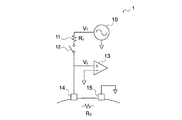
図1は、本実施形態に係る生体信号測定装置1の構成を示す模式図である。生体信号測定装置1は、ユーザの頭表に接続され、ユーザの脳波を測定する装置(脳波計)であるものとするがこれに限られず、筋電図、心電図、体脂肪率等、生体(ヒトを含む動物)において生じる生体信号を測定することが可能な装置であるものとすることができる。同図に示すように生体信号測定装置1は、電圧源10、抵抗器11、スイッチ12、増幅器13、測定電極14及びニュートラル電極15を有する。
[Configuration of biological signal measuring apparatus]
FIG. 1 is a schematic diagram showing a configuration of a biological signal measuring apparatus 1 according to the present embodiment. The biological signal measuring device 1 is connected to the user's head surface and is a device (electroencephalograph) that measures the user's brain waves, but is not limited to this, and the living body (electromyogram, electrocardiogram, body fat percentage, etc.) It can be a device capable of measuring biological signals generated in animals including humans). As shown in the figure, the biological signal measuring apparatus 1 includes a
電圧源10は抵抗器11に接続され、抵抗器11はスイッチ12に接続されている。スイッチ12は測定電極14に接続され、増幅器13はスイッチ12と測定電極14の間に接続されている。ニュートラル電極15はグランドに接続されている。同図に示すように、測定電極14とニュートラル電極15はユーザの頭表に装着され、導電性ペースト等を介して電気的に接続されている。
The
電圧源10は、一般的な交流電圧源を用いることができる。周波数や電圧は特に限定されないが、例えば周波数10Hz、電圧振幅±500μVとすることができる。以下、電圧源10による印加電圧をV1とする。
As the
抵抗器11は、印加電圧を接触抵抗(後述)との間で分圧する。以下、抵抗器11の抵抗値をR1とする。抵抗値R1の詳細については後述する。
The
スイッチ12は、回路の開閉を可能とする。詳細は後述するが、生体信号測定装置1においては、スイッチ12の開閉により接触抵抗の測定と生体信号(脳波等)の測定を切り替えることが可能となっている。
The
増幅器13は、測定電極14が+端子に、グランドが−端子に接続され、増幅器13によって分圧された電圧V0を増幅して出力する。増幅器13は一般的なオペアンプ(オペレーショナル・アンプリファイア)を用いることが可能である。
The
測定電極14は、生体表面(ここでは、ユーザの頭表)に接触し、電気的に接続される。測定電極14は、ユーザの頭表の所定の位置、例えば国際10−20法によって規定された位置に装着されるものとすることが可能である。また、測定電極14は複数基が設けられることも可能である。
The
測定電極14の構造は特に限定されないが、導電性ペーストが塗布されて用いられる導電性部材や、導電性液体を含浸する弾性部材等とすることができる。測定電極14と生体表面の接触抵抗は、生体表面の性状や取り付け方によって異なるが、通常は数十〜数百KΩ程度である。
The structure of the
ニュートラル電極15は、測定電極14と同様に生体表面に接触し、電気的に接続される。ニュートラル電極15は、脳波の影響の小さい位置、例えばユーザの耳朶やこめかみ等に装着されるものとすることができる。ニュートラル電極15は測定電極14と同様の構造とすることができる。
The
[生体信号測定装置の動作]
電圧源10から電圧(以下、電源電圧)V1が印加されている状態でスイッチ12がONされると、微小な電流Iが抵抗器11を通過して、測定電極14からユーザの頭部を介し、ニュートラル電極15に流れる。したがって、測定電極14とユーザの頭表の接触抵抗、ユーザの頭部の抵抗、ユーザの頭表とニュートラル電極15の接触抵抗の和(以下、生体の抵抗成分)を抵抗値R2とすると、以下の(式1)が成り立つ。
[Operation of biological signal measuring device]
When the
V1=R1・I+R2・I (式1) V 1 = R 1 · I + R 2 · I (Formula 1)
また、増幅器13において検出される電圧(以下、検出電圧)V0は、以下の(式2)で表される。
In addition, a voltage (hereinafter, detected voltage) V 0 detected by the
V0=I・R2 (式2) V 0 = I · R 2 (Formula 2)
上記(式1)及び(式2)から電流Iを消去すると、次の(式3)が得られる。 When the current I is eliminated from the above (Formula 1) and (Formula 2), the following (Formula 3) is obtained.
V0=V1・R2/(R1+R2) (式3) V 0 = V 1 · R 2 / (R 1 + R 2 ) (Formula 3)
(式3)を変形すると、次の(式4)が得られる。 By transforming (Equation 3), the following (Equation 4) is obtained.
R2=R1・V0/(V1−V0) (式4) R 2 = R 1 · V 0 / (V 1 −V 0 ) (Formula 4)
このようにして、増幅器13において検出される検出電圧V0から生体の抵抗成分の抵抗値R2を求めることができる。上記(式1)に示すように、電源電圧V1が抵抗器11の抵抗値R1と生体の成功成分の抵抗値R2によって分圧されるため、検出電圧V0は抵抗値R1によって異なる。
In this way, the resistance value R 2 of the resistance component of the living body can be obtained from the detection voltage V 0 detected by the
ここで、本技術に係る生体信号測定装置1においては、抵抗器11の抵抗値R1を、測定したい抵抗値R2の範囲の対数中心値とする。測定したい抵抗値R2の範囲は、使用する測定電極14の種類や生体表面の装着方法(導電性ペーストの有無等)に応じて任意に設定することが可能である。抵抗値R1をこのように設定することにより、抵抗値R2の測定範囲を広げ、且つ高精度な測定が可能となる。
Here, in the biological signal measuring device 1 according to the present technique, the resistance value R 1 of the
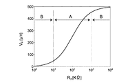
具体的には、測定したい抵抗値R2の範囲が10KΩ〜1MΩであるとすると、抵抗値R1を上記範囲の対数中心値である100KΩとする。図2は抵抗値R1を100KΩとし、電圧源10の振幅を±500μVとした場合の生体の抵抗成分の抵抗値R2と検出電圧V0の相関を示すグラフである。
Specifically, assuming that the range of the resistance value R 2 to be measured is 10 KΩ to 1 MΩ, the resistance value R 1 is set to 100 KΩ, which is the logarithmic center value of the above range. FIG. 2 is a graph showing the correlation between the resistance value R 2 of the resistance component of the living body and the detected voltage V 0 when the resistance value R 1 is 100 KΩ and the amplitude of the
同図に示すように、検出電圧V0は抵抗値R1の値を中心とする範囲(図中に範囲Aとして示す)が最も傾きが大きく、当該範囲から離れた範囲(図中に範囲Bとして示す)では傾きが小さくなる。具体的には、抵抗値R2が10KΩ〜1MΩの範囲で検出電圧V0は100μV〜400μVの広い範囲で変化するのに対し、抵抗値R2が10KΩ未満では0〜100μV、1MΩ超では400μV〜500μVと、それぞれ比較的狭い範囲の変化となる。これは、範囲Aにおいては抵抗値R2が微小に変化しても検出電圧V0が変動すること、即ち抵抗値R2の高い検出精度(分解能)が得られることを意味する。 As shown in the figure, the detection voltage V 0 has the largest inclination in the range centered on the resistance value R 1 (shown as range A in the figure) and the range far from the range (range B in the figure). The slope becomes smaller. Specifically, the detection voltage V 0 varies in a wide range of 100 μV to 400 μV when the resistance value R 2 is in the range of 10 KΩ to 1 MΩ, whereas it is 0 to 100 μV when the resistance value R 2 is less than 10 KΩ, and 400 μV when the resistance value R 2 exceeds 1 MΩ. Each change is in a relatively narrow range of ˜500 μV. This means that in the range A, the detection voltage V 0 varies even if the resistance value R 2 slightly changes, that is, high detection accuracy (resolution) of the resistance value R 2 can be obtained.
一方、範囲Bにおいては高い検出精度を得ることはできないが、抵抗値が十分小さければ、生体信号測定に与える抵抗値R2の影響は無視することができ、一方で抵抗値が異常に大きければ、測定電極14が生体表面から外れていると判断できる。したがって、いずれの場合であっても、抵抗値R2の概算値さえ取得できれば、詳細な値を取得する必要性は乏しいといえる。
On the other hand, it is not possible to obtain a high detection accuracy in a range B, if the resistance value is sufficiently small, influence of the resistance value R 2 which gives the bio-signal measurement can be ignored, while if the resistance value is abnormally large It can be determined that the
即ち、本技術に係る生体信号測定装置1においては、抵抗器11の抵抗値R1を、測定したい生体の抵抗成分の抵抗値R2の範囲の対数中心値とすることにより、抵抗値R2を必要な範囲で高精度に測定することが可能である。
That is, in the biological signal measuring device 1 according to the present technique, the resistance value R 1 of the
また、生体信号測定装置1は、スイッチ12の開閉により接触抵抗測定と生体信号(脳波等)測定の切替が可能に構成されている。具体的には、スイッチ12がONのときには、上述のように電圧源10から電圧が印加され、接触抵抗が測定される。スイッチ12がOFFのときには、測定電極14の信号が増幅器13によって増幅され、生体信号が測定される。
In addition, the biological signal measuring apparatus 1 is configured to be able to switch between contact resistance measurement and biological signal (such as brain waves) measurement by opening and closing the
図3は、生体信号測定装置1による接触抵抗測定及び生体信号測定の動作を示す模式図である。同図に示すように、生体信号測定の前にスイッチ12をONとして接触抵抗測定を実施し、接触抵抗が所定範囲以内ならばスイッチ12をOFFとして生体信号測定を開始するものとすることができる。その後、生体信号測定中に所定時間毎に接触抵抗測定を実施し、接触抵抗の測定や測定電極14の外れの検出等を行うものとすることができる。
FIG. 3 is a schematic diagram showing operations of contact resistance measurement and biological signal measurement by the biological signal measuring apparatus 1. As shown in the figure, the contact resistance measurement can be performed by turning on the
以上のように、本実施形態に係る生体信号測定装置1においては、必要な範囲の接触抵抗を高精度に測定し、ひいては接触抵抗の影響を受ける生体信号を高精度に測定することが可能である。 As described above, in the biological signal measuring apparatus 1 according to the present embodiment, it is possible to measure the contact resistance in a necessary range with high accuracy, and thus to measure the biological signal affected by the contact resistance with high accuracy. is there.
(第2の実施形態)
本技術の第2の実施形態に係る生体信号測定装置について説明する。本実施形態において第1の実施形態と同様の構成については説明を省略する場合がある。
(Second Embodiment)
A biological signal measurement device according to a second embodiment of the present technology will be described. In the present embodiment, description of the same configuration as that of the first embodiment may be omitted.
[生体信号測定装置の構成]
図4は、本実施形態に係る生体信号測定装置2の構成を示す模式図である。生体信号測定装置2は、ユーザの頭表に接続され、ユーザの脳波を測定する装置であるものとするがこれに限られず、筋電図、心電図、体脂肪率等、生体において生じる生体信号を測定することが可能な装置であるものとすることができる。同図に示すように生体信号測定装置2は、電圧源20、抵抗器21、スイッチ22、増幅器23、測定電極24、ニュートラル電極25、リファレンス電極26及び増幅器27を有する。
[Configuration of biological signal measuring apparatus]
FIG. 4 is a schematic diagram showing a configuration of the biological
電圧源20は抵抗器21に接続され、抵抗器21はスイッチ22に接続されている。スイッチ22は測定電極24に接続され、増幅器23はスイッチ22と測定電極24の間に接続されている。ニュートラル電極25はグランドに接続されている。リファレンス電極26は増幅器27に接続されている。同図に示すように、測定電極24、ニュートラル電極25及びリファレンス電極26はユーザの頭表に装着され、導電性ペースト等を介して電気的に接続されている。
The
電圧源20は、一般的な交流電圧源を用いることができる。周波数や電圧は特に限定されないが、例えば周波数10Hz、電圧振幅±500μVとすることができる。
As the
抵抗器21は、印加電圧を接触抵抗との間で分圧する。以下、抵抗器21の抵抗値をRsとする。抵抗器21の抵抗値Rsは第1の実施形態と同様に、高精度に測定したい接触抵抗の抵抗値の範囲の対数中心値であるものとする。
The
スイッチ22は、回路の開閉を可能とする。生体信号測定装置2においては、スイッチ22の開閉により接触抵抗の測定と生体信号の測定を切り替えることが可能となっている。
The switch 22 can open and close the circuit. In the biological
増幅器23は、測定電極24が+端子に、グランドが−端子に接続され、増幅器23によって分圧された電圧を増幅して出力する。以下、増幅器23の増幅率を増幅率A、出力電圧を検出電圧Vaとする。増幅器23は一般的なオペアンプ(オペレーショナル・アンプリファイア)を用いることが可能である。
The
測定電極24は、生体表面に接触し、電気的に接続される。測定電極24は、ユーザの頭表の所定の位置、例えば国際10−20法によって規定された位置に装着されるものとすることが可能である。また、測定電極24は複数基が設けられることも可能である。
The
ニュートラル電極25は、測定電極24と同様に生体表面に接触し、電気的に接続される。ニュートラル電極25は、脳波の影響の小さい位置、例えばユーザの耳朶やこめかみ等に装着されるものとすることができる。ニュートラル電極25は測定電極24と同様の構造とすることができる。
The
リファレンス電極26は、測定電極24及びニュートラル電極25と同様に生体表面に接触し、電気的に接続される。リファレンス電極26は、雑音の少ない位置、例えば頭頂部付近に装着されるものとすることができる。リファレンス電極26は測定電極24と同様の構造とすることができる。
Similar to the
増幅器27は、リファレンス電極26が+端子に、グランドが−端子に接続され、リファレンス電極26の検出する信号を増幅して出力する。以下、増幅器27の増幅率を増幅率B、出力電圧を検出電圧Vbとする。増幅器27は一般的なオペアンプを用いることが可能である。
The
[生体信号測定装置の動作]
電圧源20から電圧(以下、電源電圧Vi)が印加されている状態でスイッチ22がONされると、微小な電流が抵抗器21を通過して、測定電極24からユーザの頭部を介し、ニュートラル電極25に流れる。したがって、測定電極24とユーザの頭表の接触抵抗を抵抗値Ra、リファレンス電極26とユーザの頭表の接触抵抗を抵抗値Rb、ニュートラル電極25とユーザの頭表の接触抵抗を抵抗値Rcとすると、以下の(式5)及び(式6)が成り立つ。
[Operation of biological signal measuring device]
When the switch 22 is turned on while a voltage (hereinafter referred to as the power supply voltage Vi) is applied from the
Va=(Ra+Rc)/(Ra+Rc+Rs)・A・Vi (式5) Va = (Ra + Rc) / (Ra + Rc + Rs) · A · Vi (Formula 5)
Vb=Rc/(Ra+Rc+Rs)・B・Vi (式6) Vb = Rc / (Ra + Rc + Rs) · B · Vi (Formula 6)
上記(式5)を変形すると以下の(式7)が得られ、上記(式6)を変形すると、以下の(式8)が得られる。 When the above (formula 5) is modified, the following (formula 7) is obtained, and when the above (formula 6) is transformed, the following (formula 8) is obtained.
(AVi−Va)Ra+(AVi−Va)Rc=VaRs (式7) (AVi−Va) Ra + (AVi−Va) Rc = VaRs (Formula 7)
VbRa+(Vb−BVi)Rc=−VbRs (式8) VbRa + (Vb−BVi) Rc = −VbRs (Formula 8)
上記(式7)及び上記(式8)は抵抗値Raと抵抗値Rcの2元1次連立方程式であるので、抵抗値Raと抵抗値Rcをそれぞれ求めることができる。 Since (Equation 7) and (Equation 8) are binary linear equations of the resistance value Ra and the resistance value Rc, the resistance value Ra and the resistance value Rc can be obtained respectively.
このようにして、増幅器23及び増幅器27において検出される検出電圧Va及び検出電圧Vbから抵抗値Ra及び抵抗値Rcを求めることができる。上記(式5)及び上記(式6)に示すように、電源電圧Viが抵抗器21の抵抗値Rsと各電極の接触抵抗によって分圧されるため、検出電圧Va及び検出電圧Vbは抵抗値Rsによって異なる。
In this way, the resistance value Ra and the resistance value Rc can be obtained from the detection voltage Va and the detection voltage Vb detected by the
ここで、第1の実施形態と同様に抵抗器21の抵抗値Rsを、測定したい接触抵抗の抵抗値Raの範囲の対数中心値とすることにより、抵抗値Raを必要な範囲で高精度に測定することが可能である。
Here, similarly to the first embodiment, the resistance value Rs of the
また、生体信号測定装置2は、スイッチ22の開閉により接触抵抗測定と生体信号(脳波等)測定の切替が可能に構成されている。具体的には、スイッチ22がONのときには、上述のように電圧源20から電圧が印加され、接触抵抗が測定される。スイッチ22がOFFのときには、増幅器23によって測定電極24とリファレンス電極26の信号の差分が増幅(差動増幅)され、生体信号が測定される。
The biological
本実施形態に係る生体信号測定装置2においては、各電極の接触抵抗を得ることができるため、接触抵抗が異常に大きい場合、即ち電極が外れている場合に、それをユーザに伝達する構成とすることも可能である。
In the biological
例えば、生体信号測定装置2は取得した接触抵抗値をPC(Personal computer)に無線通信等により送信するものとすることができる。図5は、PCのディスプレイに表示される各電極の接触抵抗値を示す模式図である。同図に示すように各電極の接触抵抗値が表示され、接触抵抗値が閾値を超える場合には表示や音声等によってユーザに電極の接触性の改善を促すようにすることも可能である。
For example, the biological
以上のように、本実施形態に係る生体信号測定装置2においては、必要な範囲の接触抵抗を高精度に測定し、ひいては接触抵抗の影響を受ける生体信号を高精度に測定することが可能である。
As described above, in the biological
なお、本技術は以下のような構成も採ることができる。 In addition, this technique can also take the following structures.
(1)
電圧源と、
上記電圧源に接続され、生体に接触する測定電極と、
上記電圧源と上記測定電極の間に接続された抵抗器と、
上記抵抗器と上記測定電極の間の電位を増幅する第1の増幅器と、
を具備する生体信号測定装置。
(1)
A voltage source;
A measurement electrode connected to the voltage source and in contact with the living body;
A resistor connected between the voltage source and the measurement electrode;
A first amplifier that amplifies the potential between the resistor and the measurement electrode;
A biological signal measuring device comprising:
(2)
(1)に記載の生体信号測定装置であって、
上記抵抗器は、上記測定電極と上記生体の接触抵抗の抵抗値範囲のうち、測定したい抵抗値範囲の対数中心値となる抵抗値を有する
生体信号測定装置。
(2)
The biological signal measuring device according to (1),
The said resistor has a resistance value used as the logarithm center value of the resistance value range to measure among the resistance value range of the contact resistance of the said measurement electrode and the said biological body.
(3)
(1)又は(2)に記載の生体信号測定装置であって、
請求項2に記載の生体信号測定措置であって、
上記抵抗値範囲は、10KΩ以上1MΩ以下の範囲であり、
上記抵抗器は、100KΩの抵抗値を有する
生体信号測定装置。
(3)
The biological signal measuring device according to (1) or (2),
The biosignal measurement measure according to
The resistance value range is a range of 10 KΩ to 1 MΩ,
The resistor has a resistance value of 100 KΩ.
(4)
(1)から(3)のうちいずれか1つに記載の生体信号測定装置であって、
請求項1に記載の生体信号測定装置であって、
上記抵抗器と、上記測定電極の間の接続を開閉することが可能なスイッチ
をさらに具備する
生体信号測定装置。
(4)
The biological signal measuring device according to any one of (1) to (3),
The biological signal measuring device according to claim 1,
The biological signal measuring device further comprising: a switch capable of opening and closing a connection between the resistor and the measurement electrode.
(5)
(1)から(4)のうちいずれか1つに記載の生体信号測定装置であって、
第2の増幅器と、
上記生体に接触し、上記第2の増幅器に接続されたリファレンス電極
をさらに具備する生体信号測定装置。
(5)
The biological signal measuring device according to any one of (1) to (4),
A second amplifier;
A biological signal measuring device further comprising a reference electrode in contact with the living body and connected to the second amplifier.
1、2…生体信号測定装置
10、20…電圧源
11、21…抵抗器
12、22…スイッチ
13、23…増幅器
14、24…測定電極
15、25…ニュートラル電極
26…リファレンス電極
27…増幅器
DESCRIPTION OF
Claims (4)
前記電圧源に接続され、生体に接触する測定電極と、
前記電圧源と前記測定電極の間に接続された抵抗器と、
前記抵抗器と前記測定電極の間の電位を増幅する第1の増幅器と、
を具備し、
前記抵抗器は、前記測定電極と前記生体の接触抵抗の抵抗値範囲のうち、測定したい抵抗値範囲の対数中心値となる抵抗値を有する
生体信号測定装置。 A voltage source;
A measurement electrode connected to the voltage source and in contact with the living body;
A resistor connected between the voltage source and the measurement electrode;
A first amplifier that amplifies the potential between the resistor and the measurement electrode;
Equipped with,
The said resistor is a biological signal measuring device which has a resistance value used as the logarithm center value of the resistance value range to measure among the resistance value range of the contact resistance of the said measurement electrode and the said biological body .
前記抵抗値範囲は、10KΩ以上1MΩ以下の範囲であり、
前記抵抗器は、100KΩの抵抗値を有する
生体信号測定装置。 The biosignal measurement measure according to claim 1 ,
The resistance value range is a range of 10 KΩ to 1 MΩ,
The resistor has a resistance value of 100 KΩ.
前記抵抗器と、前記測定電極の間の接続を開閉することが可能なスイッチ
をさらに具備する
生体信号測定装置。 The biological signal measuring device according to claim 1 or 2 ,
The biological signal measuring device further comprising: a switch capable of opening and closing a connection between the resistor and the measurement electrode.
第2の増幅器と、
前記生体に接触し、前記第2の増幅器に接続されたリファレンス電極と
をさらに具備する生体信号測定装置。 The biological signal measuring device according to any one of claims 1 to 3 ,
A second amplifier;
A biological signal measuring device further comprising: a reference electrode that is in contact with the living body and connected to the second amplifier.
Priority Applications (5)
| Application Number | Priority Date | Filing Date | Title |
|---|---|---|---|
| JP2011205582A JP5935272B2 (en) | 2011-09-21 | 2011-09-21 | Biological signal measuring device |
| CN201280045034.1A CN103796580B (en) | 2011-09-21 | 2012-09-03 | Biological signal measuring device |
| PCT/JP2012/005569 WO2013042322A1 (en) | 2011-09-21 | 2012-09-03 | Biological signal measuring device |
| EP12832942.2A EP2759260A4 (en) | 2011-09-21 | 2012-09-03 | Biological signal measuring device |
| US14/235,493 US9655541B2 (en) | 2011-09-21 | 2012-09-03 | Biosignal measurement apparatus |
Applications Claiming Priority (1)
| Application Number | Priority Date | Filing Date | Title |
|---|---|---|---|
| JP2011205582A JP5935272B2 (en) | 2011-09-21 | 2011-09-21 | Biological signal measuring device |
Publications (3)
| Publication Number | Publication Date |
|---|---|
| JP2013066526A JP2013066526A (en) | 2013-04-18 |
| JP2013066526A5 JP2013066526A5 (en) | 2014-10-30 |
| JP5935272B2 true JP5935272B2 (en) | 2016-06-15 |
Family
ID=47914115
Family Applications (1)
| Application Number | Title | Priority Date | Filing Date |
|---|---|---|---|
| JP2011205582A Expired - Fee Related JP5935272B2 (en) | 2011-09-21 | 2011-09-21 | Biological signal measuring device |
Country Status (5)
| Country | Link |
|---|---|
| US (1) | US9655541B2 (en) |
| EP (1) | EP2759260A4 (en) |
| JP (1) | JP5935272B2 (en) |
| CN (1) | CN103796580B (en) |
| WO (1) | WO2013042322A1 (en) |
Families Citing this family (5)
| Publication number | Priority date | Publication date | Assignee | Title |
|---|---|---|---|---|
| GB2536163B (en) | 2013-10-17 | 2017-11-15 | Monica Healthcare Ltd | Apparatus and method for detecting an abdominal electrophysiological signal |
| CN107085013B (en) * | 2017-06-08 | 2024-01-09 | 深圳市松恩电子科技有限公司 | Biological recognition device |
| JP7149613B2 (en) * | 2017-10-20 | 2022-10-07 | 株式会社Lifescapes | Rehabilitation support system, electroencephalogram measurement system control method, program, and non-temporary recording medium |
| US11744501B2 (en) | 2020-05-07 | 2023-09-05 | GE Precision Healthcare LLC | Multi-sensor patch |
| CN112401898B (en) * | 2020-11-11 | 2024-03-12 | 西安臻泰智能科技有限公司 | High-precision electroencephalogram signal acquisition method and device |
Family Cites Families (8)
| Publication number | Priority date | Publication date | Assignee | Title |
|---|---|---|---|---|
| JPS498557B1 (en) * | 1970-02-02 | 1974-02-27 | ||
| JPS63314473A (en) * | 1987-06-17 | 1988-12-22 | Nippon Denki Sanei Kk | Electrode contact resistance measuring display apparatus |
| JPH1062463A (en) * | 1996-08-22 | 1998-03-06 | Sony Corp | Method for measuring contact resistance of biological signal measuring electrode |
| JP2003180647A (en) * | 2001-12-14 | 2003-07-02 | Yamato Scale Co Ltd | Body fat meter |
| JP4239836B2 (en) * | 2004-01-30 | 2009-03-18 | オムロンヘルスケア株式会社 | Biological information measuring device |
| CN2912512Y (en) * | 2006-05-17 | 2007-06-20 | 杨振江 | ECG detection circuit with excellent noise suppressing function |
| JP4289413B2 (en) * | 2007-03-26 | 2009-07-01 | 株式会社デンソー | Biological information measuring device |
| WO2009023488A1 (en) * | 2007-08-10 | 2009-02-19 | Consolidated Research, Inc. | Apparatus and method for high-speed determination of bioelectric electrode impedances |
-
2011
- 2011-09-21 JP JP2011205582A patent/JP5935272B2/en not_active Expired - Fee Related
-
2012
- 2012-09-03 EP EP12832942.2A patent/EP2759260A4/en not_active Ceased
- 2012-09-03 WO PCT/JP2012/005569 patent/WO2013042322A1/en active Application Filing
- 2012-09-03 US US14/235,493 patent/US9655541B2/en active Active
- 2012-09-03 CN CN201280045034.1A patent/CN103796580B/en not_active Expired - Fee Related
Also Published As
| Publication number | Publication date |
|---|---|
| US20140187997A1 (en) | 2014-07-03 |
| CN103796580A (en) | 2014-05-14 |
| US9655541B2 (en) | 2017-05-23 |
| CN103796580B (en) | 2016-03-16 |
| EP2759260A4 (en) | 2015-04-22 |
| EP2759260A1 (en) | 2014-07-30 |
| JP2013066526A (en) | 2013-04-18 |
| WO2013042322A1 (en) | 2013-03-28 |
Similar Documents
| Publication | Publication Date | Title |
|---|---|---|
| JP6162366B2 (en) | Biological signal measuring apparatus and method, unit measuring instrument therefor, and recording medium according to the method | |
| US10952633B2 (en) | Method and apparatus for measuring bioimpedance | |
| US8694084B2 (en) | Non-contact biopotential sensor | |
| JP5935272B2 (en) | Biological signal measuring device | |
| KR20110135296A (en) | Apparatus and method for measuring biological signal | |
| Grimnes et al. | Electrodermal activity by DC potential and AC conductance measured simultaneously at the same skin site | |
| US9144387B2 (en) | Electrode for measuring bio potential, method of manufacturing the electrode, and system for measuring physiological signal | |
| JP7039002B2 (en) | Wearable biosensor and noise canceling circuit | |
| KR102083559B1 (en) | Electrode for living body, apparatus and method for processing biological signal | |
| Acuña et al. | Eye-tracking capabilities of low-cost EOG system | |
| Yan et al. | Challenges of physiological signal measurements using electrodes: Fudamentals to understand the instrumentation | |
| JP2012205632A (en) | Contact state detecting circuit, biological signal acquisition device, and health equipment | |
| Gawali et al. | Implementation of ECG sensor for real time signal processing applications | |
| Saadi et al. | Electrode-gel-skin interface characterization and modeling for surface biopotential recording: Impedance measurements and noise | |
| Svärd et al. | Design and evaluation of a capacitively coupled sensor readout circuit, toward contact-less ECG and EEG | |
| US9968301B2 (en) | Body-driven pseudorandom signal injection for biomedical acquisition channel calibration | |
| KR20120086565A (en) | Apparatus and method for measuring biological including multiple unit measurer | |
| Gargiulo et al. | Giga-ohm high-impedance FET input amplifiers for dry electrode biosensor circuits and systems | |
| CN106028922B (en) | Active bottom-resistive electrode | |
| JP6796778B2 (en) | Biological signal measuring device, electroencephalograph, and control method | |
| KR101581866B1 (en) | CMRR improvement device for measuring multi-channel Electroencephalogram signal | |
| Megalingam et al. | Wheeled patient monitoring system | |
| KR101772202B1 (en) | Monitoring device and method for attachment status of biopotential electrodes | |
| WO2023106160A1 (en) | Biological signal detection device | |
| US20230270367A1 (en) | Apparatus for biopotential measurement |
Legal Events
| Date | Code | Title | Description |
|---|---|---|---|
| A521 | Request for written amendment filed |
Free format text: JAPANESE INTERMEDIATE CODE: A523 Effective date: 20140916 |
|
| A621 | Written request for application examination |
Free format text: JAPANESE INTERMEDIATE CODE: A621 Effective date: 20140916 |
|
| A131 | Notification of reasons for refusal |
Free format text: JAPANESE INTERMEDIATE CODE: A131 Effective date: 20151006 |
|
| A521 | Request for written amendment filed |
Free format text: JAPANESE INTERMEDIATE CODE: A523 Effective date: 20151112 |
|
| TRDD | Decision of grant or rejection written | ||
| A01 | Written decision to grant a patent or to grant a registration (utility model) |
Free format text: JAPANESE INTERMEDIATE CODE: A01 Effective date: 20160412 |
|
| A61 | First payment of annual fees (during grant procedure) |
Free format text: JAPANESE INTERMEDIATE CODE: A61 Effective date: 20160425 |
|
| R151 | Written notification of patent or utility model registration |
Ref document number: 5935272 Country of ref document: JP Free format text: JAPANESE INTERMEDIATE CODE: R151 |
|
| R250 | Receipt of annual fees |
Free format text: JAPANESE INTERMEDIATE CODE: R250 |
|
| R250 | Receipt of annual fees |
Free format text: JAPANESE INTERMEDIATE CODE: R250 |
|
| LAPS | Cancellation because of no payment of annual fees |