[1.パチンコ機の全体構造]
以下、図面を参照して本発明の好適な実施形態について、図面を参照して説明する。まず、図1乃至図7を参照して実施形態に係るパチンコ機の全体について説明する。
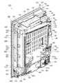
図1は、実施形態に係るパチンコ機の外枠に対して本体枠を開放し、本体枠に対して扉枠を開放した状態を示す斜視図である。図2は、パチンコ機の正面図であり、図3は、パチンコ機の右側面図である。また、図4は、パチンコ機の平面図であり、図5は、パチンコ機の背面図である。更に、図6は、パチンコ機を構成する外枠、本体枠、遊技盤、扉枠の後方から見た分解斜視図であり、図7は、パチンコ機を構成する外枠、本体枠、遊技盤、扉枠の前方から見た分解斜視図である。
[1. Overall structure of pachinko machine]
DESCRIPTION OF EXEMPLARY EMBODIMENTS Hereinafter, preferred embodiments of the invention will be described with reference to the drawings. First, the entire pachinko machine according to the embodiment will be described with reference to FIGS. 1 to 7.
FIG. 1 is a perspective view illustrating a state in which a main body frame is opened with respect to an outer frame of the pachinko machine according to the embodiment and a door frame is opened with respect to the main body frame. FIG. 2 is a front view of the pachinko machine, and FIG. 3 is a right side view of the pachinko machine. 4 is a plan view of the pachinko machine, and FIG. 5 is a rear view of the pachinko machine. 6 is an exploded perspective view of the outer frame, main body frame, game board, and door frame constituting the pachinko machine, and FIG. 7 is an outer frame, main body frame, game board constituting the pachinko machine. It is the disassembled perspective view seen from the front of the door frame.
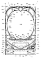
図1乃至図7において、本実施形態に係るパチンコ機1は、遊技ホールの島設備(図示しない)に設置される外枠2と、外枠2に開閉自在に軸支され前側が開放された箱枠状の本体枠3と、本体枠3に前側から装着固定され遊技媒体としての遊技球が打ち込まれる遊技領域1100を有した遊技盤4と、本体枠3及び遊技盤4の前面を遊技者側から閉鎖するように本体枠3に対して開閉自在に軸支された扉枠5とを備えている。このパチンコ機1の扉枠5には、遊技盤4の遊技領域1100が遊技者側から視認可能となるように形成された遊技窓101と、遊技窓101の下方に配置され遊技球を貯留する皿状の上皿301及び下皿302と、上皿301に貯留された遊技球を遊技盤5の遊技領域1100内へ打ち込むために遊技者が操作するハンドル装置500と、を備えている。
1 to 7, a pachinko machine 1 according to the present embodiment has an outer frame 2 installed in an island facility (not shown) of a game hall, and is pivotally supported by the outer frame 2 so as to be openable and closable. A game board 4 having a box-shaped main body frame 3, a game area 1100 in which a game ball as a game medium is inserted and fixed to the main body frame 3 from the front side, and a front face of the main body frame 3 and the game board 4 A door frame 5 that is pivotally supported to be openable and closable with respect to the main body frame 3 so as to be closed from the side. The door frame 5 of the pachinko machine 1 stores a game window 101 formed so that the game area 1100 of the game board 4 can be viewed from the player side, and a game ball placed below the game window 101 and storing game balls. A dish-shaped upper plate 301 and lower plate 302, and a handle device 500 operated by the player to drive the game balls stored in the upper plate 301 into the game area 1100 of the game board 5, are provided.
本例のパチンコ機1は、図示するように、正面視において、外枠2、本体枠3、及び扉枠5が夫々上下方向へ延びた縦長の矩形状に形成されており、夫々の左右方向の横幅が略同じ寸法とされていると共に、上下方向の縦幅の寸法が、外枠2に対して本体枠3及び扉枠5の寸法が若干短く形成されている。そして、本体枠3及び扉枠5よりも下側の位置において、外枠2の前面に装飾カバー23が取付けられており、扉枠5及び装飾カバー23によって外枠2の前面が完全に閉鎖されるようになっている。また、外枠2、本体枠3、及び扉枠5は、上端が略揃うように夫々が配置されると共に、外枠2の左端前側の位置で本体枠3及び扉枠5が回転可能に軸支されており、外枠2に対して本体枠3及び扉枠5の右端が前側へ移動することで開状態となるようになっている。
As shown in the figure, the pachinko machine 1 of this example is formed in a vertically long rectangular shape in which the outer frame 2, the main body frame 3, and the door frame 5 extend in the vertical direction when viewed from the front. The width of the main body frame 3 and the door frame 5 are slightly shorter than the outer frame 2 in terms of the vertical width. A decorative cover 23 is attached to the front surface of the outer frame 2 at a position below the main body frame 3 and the door frame 5, and the front surface of the outer frame 2 is completely closed by the door frame 5 and the decorative cover 23. It has become so. The outer frame 2, the main body frame 3, and the door frame 5 are arranged so that their upper ends are substantially aligned, and the main body frame 3 and the door frame 5 can be rotated at a position on the left end front side of the outer frame 2. The right end of the main body frame 3 and the door frame 5 moves to the front side with respect to the outer frame 2 so as to be in an open state.
このパチンコ機1は、正面視において、略円形状の遊技窓101を介して遊技球が打ち込まれる遊技領域1100が望むようになっており、その遊技窓101の下側に前方へ突出するように二つの上皿301及び下皿302が上下に配置されている。また、扉枠5の前面右下隅部には、遊技者が操作するためのハンドル装置500が配置されており、上皿301内に遊技球が貯留されている状態で遊技者がハンドル装置500を回転操作すると、その回転角度に応じた打球強さで上皿301内の遊技球が遊技盤4の遊技領域1100内へ打ち込まれて、遊技をすることができるようになっている。
The pachinko machine 1 is desired to have a game area 1100 into which a game ball is driven through a substantially circular game window 101 in a front view, and protrudes forward to the lower side of the game window 101. Two upper plates 301 and lower plates 302 are arranged one above the other. In addition, a handle device 500 for the player to operate is disposed at the lower right corner of the front surface of the door frame 5. When the rotation operation is performed, the game ball in the upper plate 301 is driven into the game area 1100 of the game board 4 with a hitting strength corresponding to the rotation angle, and a game can be played.
なお、詳細は後述するが、扉枠5の遊技窓101は、透明なガラスユニット590によって閉鎖されており、遊技者から遊技領域1100内を視認することができるものの、遊技者が遊技領域1100内へ手等を挿入して遊技領域1100内の遊技球や障害釘、各種入賞口や役物等に触ることができないようになっている。また、本体枠3の後側には、各種の制御基板が備えられていると共に、遊技盤4の後方を覆うように閉鎖するカバー体1250備えられている。
Although the details will be described later, the game window 101 of the door frame 5 is closed by a transparent glass unit 590, and the player can visually recognize the inside of the game area 1100. However, the player can recognize the inside of the game area 1100. By inserting a hand or the like, it is impossible to touch game balls, obstacle nails, various winning holes, and bonus items in the game area 1100. Further, on the rear side of the main body frame 3, various control boards are provided, and a cover body 1250 that closes the back of the game board 4 is provided.
[1−1.外枠]
外枠2について、主として図8乃至図16を参照して説明する。図8は外枠の正面斜視図であり、図9は外枠の正面から見た分解斜視図であり、図10は外枠の正面図である。また、図11は外枠の背面斜視図であり、図12は外枠の右側面図である。更に、図13は、本体枠の上軸支金具と外枠の上支持金具との脱着構造を説明するための斜視図である。また、図14(A)は外枠の上支持金具の裏面に設けられるロック部材の取付状態を示す分解斜視図であり、(B)は(A)の図を下方から見た斜視図である。図15は、軸支ピンとロック部材との関係を説明するための上支持金具部分の裏面図である。更に、図16は、ロック部材の作用を説明するための上支持金具部分の裏面図である。
[1-1. Outer frame]
The outer frame 2 will be described mainly with reference to FIGS. FIG. 8 is a front perspective view of the outer frame, FIG. 9 is an exploded perspective view seen from the front of the outer frame, and FIG. 10 is a front view of the outer frame. FIG. 11 is a rear perspective view of the outer frame, and FIG. 12 is a right side view of the outer frame. Further, FIG. 13 is a perspective view for explaining a detaching structure between the upper shaft support fitting of the main body frame and the upper support fitting of the outer frame. 14A is an exploded perspective view showing a mounting state of the lock member provided on the back surface of the upper support fitting of the outer frame, and FIG. 14B is a perspective view of the view of FIG. . FIG. 15 is a rear view of the upper support metal part for explaining the relationship between the pivot pin and the lock member. Further, FIG. 16 is a rear view of the upper support metal part for explaining the operation of the lock member.
図8及び図9に示すように、本実施形態のパチンコ機1における外枠2は、横方向へ延びる上下の上枠板10及び下枠板11と、縦(上下)方向へ延びる左右の側枠板12,13と、夫々の枠板10,11,12,13の端部を連結する四つの連結部材14と、を備えており、連結部材14で各枠板10,11,12,13同士を連結することで縦長の矩形状(方形状)に組立てられている。本例の外枠2における上枠板10及び下枠板11は、所定厚さの無垢材(例えば、木材、合板、等)により形成されており、左右両端の前後方向の略中央に、上下に貫通し左右方向中央側へ窪んだ係合切欠部15が備えられている。なお、上枠板10における左側端部の上面及び前面には、その他の一般面よりも窪んだ取付段部10aが形成されており、この取付段部10aに後述する上支持金具20が取付けられるようになっている。
As shown in FIGS. 8 and 9, the outer frame 2 in the pachinko machine 1 according to the present embodiment includes upper and lower upper and lower frame plates 10 and 11 that extend in the horizontal direction, and left and right sides that extend in the vertical (vertical) direction. Frame plates 12 and 13, and four connecting members 14 that connect the end portions of the respective frame plates 10, 11, 12, and 13, and each of the frame plates 10, 11, 12, 13 is connected by the connecting member 14. They are assembled into a vertically long rectangular shape (square shape) by connecting them together. The upper frame plate 10 and the lower frame plate 11 in the outer frame 2 of the present example are formed of a solid material (for example, wood, plywood, etc.) having a predetermined thickness, And an engagement notch 15 that is recessed toward the center in the left-right direction. A mounting step 10a that is recessed from the other general surface is formed on the upper surface and the front surface of the left end portion of the upper frame plate 10, and an upper support fitting 20 described later is attached to the mounting step 10a. It is like that.
一方、側枠板12,13は、一定断面形状の軽量金属型材(例えば、アルミ合金)とされており、外側側面は略平坦面とされていると共に、内側側面は後端部に内側へ突出し上下方向(押出方向)に貫通する空洞を有した突出部16を備えており、強度剛性が高められている(図9及び図106を参照)。なお、側枠板12,13の外側側面及び内側側面には、上下方向へ延びた複数の溝が形成されており、パチンコ機1を遊技ホールの島設備に設置する際等に、作業者の指掛りとなってパチンコ機1を保持し易くすることができるようにっていると共に、外観の意匠性を高められるようになっている。なお、便宜上、側枠板12,13の側面に形成された複数の溝を省略して示した図面もある。
On the other hand, the side frame plates 12 and 13 are made of a lightweight metal mold (for example, aluminum alloy) having a constant cross-sectional shape, the outer side surface is a substantially flat surface, and the inner side surface protrudes inward at the rear end. The protrusion 16 having a cavity penetrating in the vertical direction (extrusion direction) is provided, and the strength rigidity is enhanced (see FIGS. 9 and 106). In addition, a plurality of grooves extending in the vertical direction are formed on the outer side surface and the inner side surface of the side frame plates 12 and 13, and when installing the pachinko machine 1 in the island facility of the game hall, etc. The pachinko machine 1 can be easily held as a finger hook, and the design of the appearance can be enhanced. For convenience, there is also a drawing in which a plurality of grooves formed on the side surfaces of the side frame plates 12 and 13 are omitted.
本例の外枠2における連結部材14は、所定厚さの金属板をプレス成型等によって屈曲塑性変形させることで形成されたものであり、上枠板10又は下枠板11に固定され左右方向へ延びた板状の水平片17と、水平片17の外側端部から上下方向の一方側へ延び側枠板12,13に固定される板状の垂直片18と、垂直片18とは反対方向へ延び上枠板10又は下枠板11の係合切欠部15内に挿入係合可能な板状の係合片19と、を有している。なお、本例では、上枠板10と左側の側枠板12とを連結する連結部材14と、上枠板10と右側の側枠板13とを連結する連結部材14とは、夫々左右非対称の形状に形成されていると共に、垂直片18が前後に分かれて形成されている。一方、下枠板11と左側の側枠板12とを連結する連結部材14と、下枠板11と右側の側枠板13とを連結する連結部材14とは、夫々左右対称の形状に形成されている。
The connecting member 14 in the outer frame 2 of this example is formed by bending and plastically deforming a metal plate having a predetermined thickness by press molding or the like, and is fixed to the upper frame plate 10 or the lower frame plate 11 in the horizontal direction. The plate-like horizontal piece 17 extending to the side, the plate-like vertical piece 18 extending from the outer end of the horizontal piece 17 to one side in the vertical direction and fixed to the side frame plates 12 and 13, and the vertical piece 18 are opposite to each other A plate-like engagement piece 19 that extends in the direction and can be inserted and engaged in the engagement notch 15 of the upper frame plate 10 or the lower frame plate 11. In this example, the connecting member 14 that connects the upper frame plate 10 and the left side frame plate 12 and the connecting member 14 that connects the upper frame plate 10 and the right side frame plate 13 are asymmetrical to each other. The vertical piece 18 is divided into front and rear parts. On the other hand, the connecting member 14 for connecting the lower frame plate 11 and the left side frame plate 12 and the connecting member 14 for connecting the lower frame plate 11 and the right side frame plate 13 are formed in symmetrical shapes, respectively. Has been.
この連結部材14は、水平片17の上面及び下面が上枠板10及び下枠板11の下面及び上面と当接すると共に、係合片19が上枠板10及び下枠板11の係合切欠部15内に挿入係合された状態で、水平片17及び係合片19を貫通して所定のビスが上枠板10及び下枠板11にねじ込まれることで、上枠板10及び下枠板11に固定されるようになっている。また、上枠板10に固定された連結部材14は、その垂直片18が側枠体12,13の上端内側側面に当接した状態で、側枠体12,13を貫通して所定のビスが垂直片18へねじ込まれることで、上枠板10と側枠板12,13とを連結することができるようになっている。なお、上枠板10に固定された連結部材14における後側の垂直片18は、側枠板12,13の突出部16内に挿入された状態で、側枠板12,13へ固定されるようになっている。更に、下枠板11に固定された連結部材14は、その垂直片18が側枠体12,13の下端内側側面に当接した状態で、側枠体12,13を貫通して所定のビスが垂直片18へねじ込まれることで、下枠板11と側枠板12,13とを連結することができるようになっており、四つの連結部材14により、上枠板10、下枠板11、及び側枠板12,13を枠状に組立てることができるようになっている。
In the connecting member 14, the upper surface and the lower surface of the horizontal piece 17 are in contact with the lower surface and the upper surface of the upper frame plate 10 and the lower frame plate 11, and the engagement piece 19 is an engagement notch between the upper frame plate 10 and the lower frame plate 11. In a state of being inserted and engaged in the portion 15, a predetermined screw passes through the horizontal piece 17 and the engagement piece 19 and is screwed into the upper frame plate 10 and the lower frame plate 11, so that the upper frame plate 10 and the lower frame It is fixed to the plate 11. Further, the connecting member 14 fixed to the upper frame plate 10 penetrates the side frames 12 and 13 with a predetermined screw in a state where the vertical piece 18 is in contact with the upper side inner side surfaces of the side frames 12 and 13. Is screwed into the vertical piece 18 so that the upper frame plate 10 and the side frame plates 12 and 13 can be connected. The rear vertical piece 18 of the connecting member 14 fixed to the upper frame plate 10 is fixed to the side frame plates 12 and 13 while being inserted into the protruding portions 16 of the side frame plates 12 and 13. It is like that. Further, the connecting member 14 fixed to the lower frame plate 11 penetrates the side frame bodies 12 and 13 with a predetermined screw in a state in which the vertical piece 18 is in contact with the lower side inner side surfaces of the side frame bodies 12 and 13. Is screwed into the vertical piece 18 so that the lower frame plate 11 and the side frame plates 12 and 13 can be connected to each other, and the upper frame plate 10 and the lower frame plate 11 are connected by the four connecting members 14. The side frame plates 12 and 13 can be assembled into a frame shape.
本例の外枠2は、上枠板10の左端上面に固定される上支持金具20と、上支持金具20と対向するように配置され左側の側枠板12における下部内側の所定位置に固定される下支持金具21と、下支持金具21の下面を支持するように配置され左右の側枠板12,13を連結するように固定される補強金具22と、補強金具22の前面に固定される装飾カバー23と、を備えている。この上支持金具20及び下支持金具21は、本体枠3及び扉枠5を開閉可能に軸支するためのものである。
The outer frame 2 of the present example is fixed to a predetermined position inside the lower portion of the left side frame plate 12 that is disposed so as to face the upper support bracket 20 and the upper support bracket 20 that is fixed to the upper surface of the left end of the upper frame plate 10. Fixed to the lower support bracket 21, the reinforcing bracket 22 arranged to support the lower surface of the lower support bracket 21 and fixed to connect the left and right side frame plates 12, 13, and fixed to the front surface of the reinforcement bracket 22. The decorative cover 23 is provided. The upper support bracket 20 and the lower support bracket 21 are for pivotally supporting the main body frame 3 and the door frame 5 so that they can be opened and closed.
まず、上支持金具20は、上枠板10に固定される板状の固定片20aと、固定片20aの前端から上枠板10の前端よりも前方へ突出する支持突出片20bと、支持突出片20bにおける前端付近の右側端から先端中央部へ向かって屈曲するように切欠かれて形成された支持鉤穴20cと、固定片20及び支持突出片20bの左端から下方へ垂下し左側の側枠板12における外側側面と当接する板状の垂下固定片20d(図14(A)を参照)と、垂下固定片20dと連続し支持突出片20bの外側縁に沿って垂下する垂下壁20e(図14を参照)と、垂下壁20eと連続し支持鉤穴20cの入口端部で内側へ向って傾斜した停止垂下部20f(図15を参照)と、を備えている。この上支持金具20における支持鉤穴20cには、後述する本体枠3における上軸支金具630の軸支ピン633(図63を参照)が着脱自在に係合されるようになっている。また、上支持金具20は、固定片20aと垂下固定片20dとによって、上枠板10と左側の側枠板12とを連結することができるようになっている。
First, the upper support fitting 20 includes a plate-like fixed piece 20a fixed to the upper frame plate 10, a support protruding piece 20b protruding forward from the front end of the fixed piece 20a to the front end of the upper frame plate 10, and a support protrusion. The support side wall 20c formed by being cut out so as to bend from the right end near the front end of the piece 20b toward the center of the tip, and the left side frame depending from the left end of the fixed piece 20 and the support protruding piece 20b. A plate-shaped hanging fixing piece 20d (see FIG. 14A) that contacts the outer side surface of the plate 12, and a hanging wall 20e that continues to the hanging fixing piece 20d and hangs along the outer edge of the support protruding piece 20b (see FIG. 14). 14) and a stop drooping portion 20f (see FIG. 15) that is continuous with the drooping wall 20e and is inclined inward at the entrance end of the supporting saddle hole 20c. A shaft support pin 633 (see FIG. 63) of an upper shaft support bracket 630 in the main body frame 3 to be described later is detachably engaged with the support hole 20c in the upper support bracket 20. Further, the upper support bracket 20 can connect the upper frame plate 10 and the left side frame plate 12 by a fixing piece 20a and a hanging fixing piece 20d.
この上支持金具20は、支持突出片20bの外側縁から垂下する垂下壁20eによって、支持突出片20bの強度が高められていると共に、詳細は後述するが、正面から見た時に支持突出片20bの裏面に配置されるロック部材27が遊技者側から視認できないように隠蔽することができ、外観の見栄えを良くすることができるようになっている。また、支持突出片20bに形成された支持鉤穴20cは、垂下壁20eが形成されない反対側(右側)の側方から先端中央部に向かって傾斜状となるようにく字状に屈曲した形状とされていると共に、支持鉤穴20cの傾斜状穴部の幅寸法は、軸支ピン633の直径よりもやや大きな寸法とされている。
The strength of the support protrusion 20b is enhanced by a hanging wall 20e depending from the outer edge of the support protrusion 20b. The details of the upper support metal 20 will be described later. The lock member 27 arranged on the back surface of the player can be concealed so that it cannot be seen from the player side, and the appearance can be improved. Further, the support hole 20c formed in the support projecting piece 20b is bent in a square shape so as to be inclined from the side of the opposite side (right side) where the hanging wall 20e is not formed toward the center of the tip. In addition, the width dimension of the inclined hole portion of the support hole 20c is slightly larger than the diameter of the pivot pin 633.
一方、下支持金具21は、補強金具22上に載置固定される水平固定片21aと、水平固定片21aの左端から上方へ立上がり左側の側枠板12の内側側面に固定される垂直固定片21bと、水平固定片21aの前端から上枠板10及び下枠板11よりも前方へ突出する板状の支持突出片21cと、支持突出片21cの前端付近から上向きに突設されたピン状の支持突起21dと、を備えている。この下支持金具21における支持突起21dには、後述する本体枠3の本体枠軸支金具644(図66等を参照)に形成された本体枠軸支が挿入されるようになっており、下支持金具21の支持突起21dを、本体枠3における本体枠軸支金具644の支持穴に挿入した後に、本体枠3の上軸支金具630の軸支ピン633を支持鉤穴20cに係止することにより簡単に本体枠3を開閉自在に軸支することができるようになっている。
On the other hand, the lower support bracket 21 includes a horizontal fixing piece 21a that is placed and fixed on the reinforcing metal fitting 22, and a vertical fixing piece that rises upward from the left end of the horizontal fixing piece 21a and is fixed to the inner side surface of the left side frame plate 12. 21b, a plate-like support projecting piece 21c projecting forward from the front end of the horizontal fixing piece 21a to the upper frame plate 10 and the lower frame plate 11, and a pin shape projecting upward from the vicinity of the front end of the support projecting piece 21c Support projections 21d. A main body frame pivot formed on a main body frame pivot bracket 644 (see FIG. 66, etc.) of the main body frame 3 to be described later is inserted into the support protrusion 21d of the lower support bracket 21. After the support protrusion 21d of the support bracket 21 is inserted into the support hole of the main body frame pivot support 644 in the main body frame 3, the pivot support pin 633 of the upper pivot support 630 of the main body frame 3 is locked to the support stud 20c. Thus, the main body frame 3 can be pivotally supported so as to be freely opened and closed.
また、本例の外枠2は、図示するように、右側の側枠板13の内側に、上下方向に所定距離離反して配置される二つの閉鎖板24,25が取付固定されている。これら閉鎖板24,25は、平面視で略L字状に形成されており、下側に配置される閉鎖板25には、前後方向に貫通する矩形状の開口25aを有している(図9を参照)。この閉鎖板24,25は、外枠2に対して本体枠3を閉じる際に、本体枠3の開放側辺に沿って取付けられる錠装置1000のフック部1054,1065(図93を参照)と係合するものであり、詳細は後述するが、錠装置1000のシリンダ錠1010に鍵を差し込んで一方に回動することにより、フック部1054,1065と閉鎖板24,25との係合が外れて本体枠3を外枠2に対して開放することができるものである。
In addition, as shown in the figure, the outer frame 2 of this example has two closing plates 24 and 25 that are disposed at a predetermined distance apart in the vertical direction inside the right side frame plate 13. The closing plates 24 and 25 are formed in a substantially L shape in a plan view, and the closing plate 25 disposed on the lower side has a rectangular opening 25a penetrating in the front-rear direction (see FIG. 9). The closing plates 24 and 25 are hook portions 1054 and 1065 (see FIG. 93) of the locking device 1000 that are attached along the open side of the main body frame 3 when the main body frame 3 is closed with respect to the outer frame 2. As will be described in detail later, the hooks 1054 and 1065 are disengaged from the closing plates 24 and 25 by inserting a key into the cylinder lock 1010 of the locking device 1000 and turning it to one side. Thus, the main body frame 3 can be opened with respect to the outer frame 2.
更に、本例の外枠2は、補強金具22の右端上面に固定される案内板26を更に備えている。この案内板26は、外枠2に対して本体枠3を閉止する際に、本体枠3をスムーズに案内するためのものであり、交換可能に装着固定されている。
Furthermore, the outer frame 2 of this example further includes a guide plate 26 fixed to the upper surface of the right end of the reinforcing metal fitting 22. This guide plate 26 is used to smoothly guide the main body frame 3 when the main body frame 3 is closed with respect to the outer frame 2, and is mounted and fixed in a replaceable manner.
また、本例の外枠2は、図14等に示すように、上支持金具20における支持突出片20bの裏面に支持されたロック部材27を更に備えており、リベット28によって支持突出片20bに対して回動可能に軸支されている。このロック部材27は、合成樹脂により形成されており、リベット28により軸支される位置から前方へ突出するストッパ部27aと、リベット28により軸支される位置から右方向へストッパ部27aよりも短く突出する操作部27bと、操作部27bに対してリベット28により軸支される位置とは反対側から突出する弾性片27cと、ストッパ部27aの先端に前方側へ膨出するように形成された円弧状の先端面27dと、を備えている。このロック部材27は、図示するように、ストッパ部27aと操作部27bとで、略L字状に形成されている。また、ロック部材27の弾性部27cは、ストッパ部27aや操作部27bよりも狭い幅に形成されていると共に、ストッパ部27aから左方へ遠ざかるに従って前方へ延びだすように形成されている。
Further, as shown in FIG. 14 and the like, the outer frame 2 of the present example further includes a lock member 27 supported on the back surface of the support projecting piece 20b in the upper support metal fitting 20, and the support projecting piece 20b is supported by a rivet 28. On the other hand, it is pivotally supported. The lock member 27 is made of synthetic resin, and has a stopper portion 27a that protrudes forward from a position that is pivotally supported by the rivet 28, and is shorter than the stopper portion 27a rightward from the position that is pivotally supported by the rivet 28. The protruding operation part 27b, the elastic piece 27c protruding from the opposite side of the position supported by the rivet 28 with respect to the operation part 27b, and the front end of the stopper part 27a are formed to bulge forward. An arcuate tip surface 27d. As shown in the figure, the lock member 27 is formed in a substantially L shape by a stopper portion 27a and an operation portion 27b. Further, the elastic portion 27c of the lock member 27 is formed to have a narrower width than the stopper portion 27a and the operation portion 27b, and is formed to extend forward as the distance from the stopper portion 27a increases.
このロック部材27は、図14(B)や図15に示すように、上支持金具20の支持突出片20bに支持した状態(通常の状態)では、弾性片27cの先端当接部が垂下壁20eの内側面と当接しており、ストッパ部27aが支持鉤穴20cの傾斜状穴部を閉塞するようになっていると共に、ストッパ部27aの先端部分が、支持鉤穴20cの傾斜状穴部の先頭空間部分を閉塞した状態とはならず、支持鉤穴20cの先頭空間部分に本体枠3の上軸支金具630の軸支ピン633を挿入可能な空間が形成された状態となっている。
As shown in FIGS. 14B and 15, the lock member 27 is configured such that the tip contact portion of the elastic piece 27 c is the hanging wall when supported by the support protrusion piece 20 b of the upper support fitting 20 (normal state). 20e is in contact with the inner surface of the stopper 20a, and the stopper 27a closes the inclined hole of the supporting hole 20c. The tip of the stopper 27a is inclined to the inclined hole of the supporting hole 20c. The head space portion is not closed, and a space in which the shaft support pin 633 of the upper shaft support fitting 630 of the main body frame 3 can be inserted is formed in the head space portion of the support hole 20c. .
本例の上支持金具20とロック部材27とを用いた軸支ピン633の支持機構は、軸支ピン633が支持鉤穴20cの傾斜状穴部の先端空間部分に挿入されてストッパ部27aの先端側方が入口端部の停止垂下部20fに対向している状態(この状態ではストッパ部27aの先端側方と停止垂下部20fとの間に僅かな隙間があり当接した状態となっていない)である通常の軸支状態においては、屈曲して形成される支持鉤穴20cの傾斜状穴部の先端空間部分に位置する軸支ピン633とストッパ部27aの先端面27dとの夫々の中心が斜め方向にずれて対向した状態となっている。そして、この通常の軸支状態においては、重量のある本体枠3を軸支している軸支ピン633が支持鉤穴20cの先端部分に当接した状態となっているので、軸支ピン633からストッパ部27aの先端面27dへの負荷がほとんどかかっていないため、ロック部材27の弾性片27cに対し負荷がかかっていない状態となっている。なお、ストッパ部27aの先端に円弧状の先端面27dを備えているので、ロック部材27を回動させるために操作部27bを回動操作した時に、ロック部材27がスムーズに回動するようになっている。また、図示では、先端面27dの円弧中心が、リベット28の中心(ロック部材27の回転中心)とされている。
The support mechanism of the pivot pin 633 using the upper support fitting 20 and the lock member 27 in this example is such that the pivot pin 633 is inserted into the tip space portion of the inclined hole portion of the support hole 20c so that the stopper portion 27a The tip side faces the stop drooping portion 20f at the inlet end (in this state, there is a slight gap between the tip side of the stopper portion 27a and the stop drooping portion 20f so that the abutting portion is in contact). In a normal shaft support state, the shaft support pin 633 positioned in the tip space portion of the inclined hole portion of the support rod hole 20c formed by bending and the tip surface 27d of the stopper portion 27a are respectively provided. The center is in a state of being offset in an oblique direction and facing each other. In this normal shaft support state, the shaft support pin 633 supporting the heavy body frame 3 is in contact with the tip end portion of the support saddle hole 20c. Since almost no load is applied to the distal end surface 27d of the stopper portion 27a, the elastic piece 27c of the lock member 27 is not loaded. In addition, since the arcuate tip end surface 27d is provided at the tip of the stopper portion 27a, the lock member 27 is smoothly rotated when the operation portion 27b is rotated to rotate the lock member 27. It has become. In the drawing, the center of the arc of the tip surface 27d is the center of the rivet 28 (the rotation center of the lock member 27).
従って、軸支ピン633が支持鉤穴20cの傾斜状穴部の傾斜に沿って抜ける方向に作用力Fがかかって円弧状の先端面27dに当接したとき、その作用力Fを、軸支ピン633と円弧状の先端面27dとの当接部分に作用する分力F1(先端面27dの円弧の法線方向)と、軸支ピン633と支持鉤穴20cの傾斜状穴部の一側内面との当接部分に作用する分力F2と、に分けたときに、分力F1の方向がリベット28の中心(ロック部材27の回転中心)を向くため、ロック部材27のストッパ部27aの先端部が支持突出片20bから外れる方向(図示の時計方向)に回転させるモーメントが働かず、軸支ピン633がロック部材27のストッパ部27aの先端部と支持鉤穴20cの傾斜状穴部の一側内面との間に挟持された状態を保持する。このため、通常の軸支状態でもあるいは軸支ピン633の作用力がロック部材27にかかった状態でも、ロック部材27の弾性片27cに常時負荷がかからず、合成樹脂で一体形成される弾性片27cのクリープによる塑性変形を防止し、長期間に亘って軸支ピン633の支持鉤穴20cからの脱落を防止することができる。なお、仮に無理な力がかかってロック部材27のストッパ部27aの先端部が支持突出片20bから外れる方向(図示の時計方向)に回転させられても、ストッパ部27aの先端部の一側方が停止垂下部20fに当接してそれ以上外れる方向に回転しないので、ロック部材27が支持突出片20bの外側にはみ出ないようになっている。
Therefore, when the acting force F is applied in the direction in which the shaft supporting pin 633 is pulled out along the inclination of the inclined hole portion of the support hole 20c and comes into contact with the arcuate tip end surface 27d, the acting force F is Component force F1 acting on the contact portion between the pin 633 and the arcuate tip end surface 27d (in the normal direction of the arc of the tip end surface 27d), and one side of the inclined hole portion of the shaft support pin 633 and the support hole 20c When divided into the component force F2 acting on the contact portion with the inner surface, the direction of the component force F1 faces the center of the rivet 28 (the rotation center of the lock member 27). The moment for rotating the tip part in the direction away from the support protruding piece 20b (clockwise in the figure) does not act, and the pivot pin 633 is formed between the tip part of the stopper part 27a of the lock member 27 and the inclined hole part of the support collar hole 20c. Maintain the state of being pinched between the inner surface of one side. To. Therefore, the elastic piece 27c of the lock member 27 is not always loaded even in a normal shaft support state or in a state where the acting force of the shaft support pin 633 is applied to the lock member 27, and is an elastic formed integrally with synthetic resin. It is possible to prevent plastic deformation due to creep of the piece 27c and to prevent the pivot pin 633 from coming off from the support hole 20c over a long period of time. Even if an excessive force is applied and the distal end portion of the stopper portion 27a of the lock member 27 is rotated in a direction away from the support projecting piece 20b (clockwise in the figure), one side of the distal end portion of the stopper portion 27a. Does not rotate in a direction in which it comes into contact with the stop drooping portion 20f and disengages any further, so that the lock member 27 does not protrude beyond the support protruding piece 20b.
なお、ストッパ部27aの先端面27dの形状は円弧状でなくても、上記した分力F1の作用により回転モーメントが生じない位置又はロック部材27をその先端部が支持突出片20bの外側に向って回転させる回転モーメントが生ずる位置にロック部材27の回転中心(リベット28により固定される軸)を位置させることにより、常時ロック部材27の弾性片27cに対しても負荷がかかることはないし、ロック部材27が回転してもストッパ部27aの先端一側方が停止垂下部20fに当接するだけであるため、ロック部材27が支持突出片20bの外側にはみ出ることもないという点を本出願人は確認している。
Even if the shape of the distal end surface 27d of the stopper portion 27a is not an arc, the position where the rotational moment does not occur due to the action of the component force F1 or the distal end portion of the lock member 27 faces the outside of the support protruding piece 20b. By positioning the rotation center of the lock member 27 (the axis fixed by the rivet 28) at a position where a rotational moment to rotate is generated, no load is applied to the elastic piece 27c of the lock member 27 at all times. Since the one side of the tip end of the stopper portion 27a only abuts against the stop drooping portion 20f even when the member 27 rotates, the present applicant points out that the lock member 27 does not protrude outside the support protruding piece 20b. I have confirmed.
本例のロック部材27の作用について図16を参照して具体的に説明する。外枠2に本体枠3を開閉自在に軸支する前提として、本体枠3の本体枠軸支金具644(図63を参照)に形成される本体枠軸支穴(図示しない)に下支持金具21の支持突起21dが挿通されていることが必要である。そのような前提において、図16(A)に示すように、本体枠3の上軸支金具630の軸支ピン633をロック部材27のストッパ部27aの側面に当接させて押し込むことにより、図16(B)に示すように、ロック部材27が弾性片27cを変形させながら反時計方向に回動させるので、軸支ピン633を支持鉤穴20cに挿入することができる。そして、軸支ピン633が支持鉤穴20cの傾斜状穴部の先頭空間部分に到達すると、図16(C)に示すように、軸支ピン633とストッパ部27aの先端側面とが当接しなくなるためロック部材27が弾性片27cの弾性力に付勢されて時計方向に回動し、ロック部材27のストッパ部27aが再度通常の状態に戻って支持鉤穴20cの入口部分を閉塞すると同時に、ストッパ部27aの先端部分が軸支ピン633と対向して軸支ピン633が支持鉤穴20cから抜け落ちないようになっている。
The action of the lock member 27 of this example will be specifically described with reference to FIG. As a premise that the main body frame 3 is pivotally supported on the outer frame 2 so as to be freely opened and closed, a lower support bracket is mounted on a main body frame pivot support hole (not shown) formed in a main body frame pivot support bracket 644 (see FIG. 63). 21 support protrusions 21d need to be inserted. Under such a premise, as shown in FIG. 16A, the shaft support pin 633 of the upper shaft support fitting 630 of the main body frame 3 is pressed against the side surface of the stopper portion 27a of the lock member 27, thereby pushing As shown in FIG. 16B, the lock member 27 rotates counterclockwise while deforming the elastic piece 27c, so that the shaft support pin 633 can be inserted into the support rod hole 20c. Then, when the shaft support pin 633 reaches the head space portion of the inclined hole portion of the support flange 20c, as shown in FIG. 16C, the shaft support pin 633 and the tip side surface of the stopper portion 27a do not contact each other. Therefore, the lock member 27 is urged by the elastic force of the elastic piece 27c and rotates in the clockwise direction, and the stopper portion 27a of the lock member 27 returns to the normal state again and closes the inlet portion of the support hole 20c. The distal end portion of the stopper portion 27a faces the shaft support pin 633 so that the shaft support pin 633 does not fall out of the support saddle hole 20c.
そして、この状態は、図16(D)に示すように、本体枠3が完全に閉じられた状態でもあるいは本体枠3の通常の開閉動作中も保持される。次いで、軸支ピン633を支持鉤穴20cから取外すためには、図16(E)に示すように、指を支持突出片20bの裏面に差し入れてロック部材27の操作部27bを反時計方向に回動することにより、ロック部材27が弾性片27cの弾性力に抗して回動し、ストッパ部27aの先端部分が支持鉤穴20cから退避した状態となるため、軸支ピン633を支持鉤穴20cから取り出すことができる。その後、本体枠3を持ち上げて、本体枠軸支金具644に形成される本体枠軸支穴と下支持金具21の支持突起21dとの係合を解除することにより、本体枠3を外枠2から取外すことができるようになっている。
This state is maintained even when the main body frame 3 is completely closed or during the normal opening / closing operation of the main body frame 3 as shown in FIG. Next, in order to remove the pivot pin 633 from the support saddle hole 20c, as shown in FIG. 16E, the finger is inserted into the back surface of the support protrusion piece 20b, and the operation portion 27b of the lock member 27 is turned counterclockwise. By rotating, the lock member 27 rotates against the elastic force of the elastic piece 27c, and the distal end portion of the stopper portion 27a is retracted from the support rod hole 20c, so that the shaft support pin 633 is supported. It can be taken out from the hole 20c. Thereafter, the main body frame 3 is lifted, and the main body frame 3 is detached from the outer frame 2 by releasing the engagement between the main body frame shaft support hole formed in the main body frame shaft support metal 644 and the support protrusion 21d of the lower support metal 21. It can be removed from.
上述したように、本例の外枠2は、外枠2の外郭を構成する上枠板10と下枠板11とを従来と同じく木製とすると共に、側枠板12,13を軽量金属(例えば、アルミ合金)の押出型材としているので、パチンコ機1を遊技場に列設される島設備に設置する場合に、島の垂直面に対し所定の角度をつけて固定する作業を行う必要があるが、そのような作業は上枠板10及び下枠板11と島とに釘を打ち付けて行われるため、釘を打ち易くすることができ、既存の島設備に本パチンコ機1を問題なく設置することができるようになっている。また、側枠板12,13を軽量金属(例えば、アルミ合金)の押出型材としているので、従来の木製の外枠と比較して強度を維持しつつ肉厚を薄く形成することが可能となり、側枠板12,13の内側に隣接する本体枠3の周壁部605(図63等を参照)の正面から見たときの左右幅を広くすることができ、左右方向の寸法の大きな遊技盤4を本体枠3に装着することができると同時に、遊技盤4の遊技領域1100を大きく形成することができるようになっている。
As described above, in the outer frame 2 of this example, the upper frame plate 10 and the lower frame plate 11 constituting the outline of the outer frame 2 are made of wood, and the side frame plates 12 and 13 are made of a lightweight metal ( For example, when the pachinko machine 1 is installed in an island facility lined up in a game hall, it is necessary to perform an operation of fixing it at a predetermined angle with respect to the vertical plane of the island. However, since such an operation is performed by nailing nails to the upper frame plate 10 and the lower frame plate 11 and the island, the nails can be easily nailed, and the pachinko machine 1 can be used without problems in existing island facilities. It can be installed. In addition, since the side frame plates 12 and 13 are made of lightweight metal (for example, aluminum alloy) extrusion mold material, it becomes possible to form a thin wall while maintaining strength as compared with a conventional wooden outer frame. The left and right widths when viewed from the front of the peripheral wall portion 605 (see FIG. 63, etc.) of the main body frame 3 adjacent to the inside of the side frame plates 12 and 13 can be widened, and the game board 4 has a large horizontal dimension. Can be mounted on the main body frame 3, and at the same time, the game area 1100 of the game board 4 can be formed large.
また、外枠2の外郭を構成する上枠板10、下枠板11、及び側枠板12,13を連結部材14で連結するようにしており、連結部材14が側枠板12,13の内面に密着して止着されると共に連結部材14と上枠板10及び下枠板11が係合した状態で止着されるので、外枠2の組付け強度を高くすることができ、頑丈な方形状の枠組みとすることができるようになっている。また、連結部材14によって上枠板10、下枠板11、及び側枠板12,13を連結した後、上支持金具20を所定の位置に取付けたときに、図10に示すように、各枠板10,11,12,13の外側面(外周面)から外側に突出する部材が存在しないので、パチンコ機1を図示しない遊技ホールの島設備に設置する際に、隣接する装置(例えば、隣接する玉貸機)と密着して取付けることができるようになっている。
Further, the upper frame plate 10, the lower frame plate 11, and the side frame plates 12, 13 constituting the outline of the outer frame 2 are connected by a connecting member 14, and the connecting member 14 is connected to the side frame plates 12, 13. Since it is fixed in close contact with the inner surface and the connecting member 14 is engaged with the upper frame plate 10 and the lower frame plate 11, the assembly strength of the outer frame 2 can be increased, and it is sturdy. It can be made into a rectangular frame. Further, after the upper frame plate 10, the lower frame plate 11, and the side frame plates 12 and 13 are connected by the connecting member 14, when the upper support fitting 20 is attached at a predetermined position, as shown in FIG. Since there is no member projecting outward from the outer surface (outer peripheral surface) of the frame plates 10, 11, 12, and 13, when the pachinko machine 1 is installed in an island facility of a game hall (not shown), an adjacent device (for example, It can be attached in close contact with the adjacent ball lending machine.
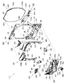
[1−2.扉枠の全体構成]
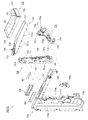
次に、上記した本体枠3の前面側に開閉自在に設けられる扉枠5について、図17乃至図25を参照して説明する。図17は扉枠の正面図であり、図18は扉枠の背面図であり、図19は扉枠を右前方から見た斜視図である。また、図20は扉枠を左前方から見た斜視図であり、図21は扉枠の右後方から見た斜視図である。更に、図22は扉枠を正面から見た分解斜視図であり、図23は扉枠を背面から見た分解斜視図である。また、図24は、扉枠からサイドスピーカ及びサイドスピーカカバーを分解して前から見た分解斜視図であり、図25は、扉枠からサイドスピーカ及びサイドスピーカカバーを分解して後から見た分解斜視図である。
[1-2. Overall structure of door frame]
Next, the door frame 5 that can be freely opened and closed on the front side of the main body frame 3 will be described with reference to FIGS. 17 to 25. 17 is a front view of the door frame, FIG. 18 is a rear view of the door frame, and FIG. 19 is a perspective view of the door frame as viewed from the right front. FIG. 20 is a perspective view of the door frame as viewed from the left front, and FIG. 21 is a perspective view of the door frame as viewed from the right rear. 22 is an exploded perspective view of the door frame as viewed from the front, and FIG. 23 is an exploded perspective view of the door frame as viewed from the back. FIG. 24 is an exploded perspective view of the side speaker and the side speaker cover as seen from the front after disassembling the door frame, and FIG. 25 is a view of the side speaker and the side speaker cover as seen from the rear after being disassembled from the door frame. It is a disassembled perspective view.
本実施形態のパチンコ機1における扉枠5は、図示するように、外形が縦長の矩形状に形成され内周形状がやや縦長の円形状(楕円形状)とされた遊技窓101を有する扉枠ベースユニット100と、扉枠ベースユニット100の前面で遊技窓101の右外周に取付けられる右サイド装飾ユニット200と、右サイド装飾ユニット200と対向し扉枠ベースユニット100の前面で遊技窓101の左外周に取付けられる左サイド装飾ユニット240と、扉枠ベースユニット100の前面で遊技窓101の上部外周に取付けられる上部装飾ユニット280と、右サイド装飾ユニット200及び左サイド装飾ユニット240の下端下側に配置され扉枠ベースユニット100の前面に取付けられる一対のサイドスピーカカバー290と、を備えている。
The door frame 5 in the pachinko machine 1 according to the present embodiment includes a gaming frame 101 having a gaming window 101 whose outer shape is formed in a vertically long rectangular shape and whose inner peripheral shape is a slightly vertically long circular shape (elliptical shape) as shown in the figure. The base unit 100, the right side decoration unit 200 attached to the right outer periphery of the gaming window 101 on the front surface of the door frame base unit 100, and the left side of the gaming window 101 on the front surface of the door frame base unit 100 facing the right side decoration unit 200. The left side decoration unit 240 attached to the outer periphery, the upper decoration unit 280 attached to the upper outer periphery of the gaming window 101 on the front surface of the door frame base unit 100, and the lower ends of the right side decoration unit 200 and the left side decoration unit 240 below the lower end. A pair of side speaker covers 290 disposed and attached to the front surface of the door frame base unit 100. .
また、扉枠5は、扉枠ベースユニット100の前面で遊技窓101の下部に取付けられる皿ユニット300と、皿ユニット300の上部中央に取付けられる操作ユニット400と、皿ユニット300を貫通して扉枠ベースユニット100の右下隅部に取付けられ遊技球の打込操作をするためのハンドル装置500と、扉枠ベースユニット100を挟んで皿ユニット300の後側に配置され扉枠ベースユニット100の後面に取付けられるファールカバーユニット540と、ファールカバーユニット540の右側で扉枠ベースユニット100の後面に取付けられる球送りユニット580と、扉枠ベースユニット100の後側に遊技窓101を閉鎖するように取付けられるガラスユニット590と、を備えている。
Further, the door frame 5 passes through the tray unit 300, the tray unit 300 attached to the lower part of the gaming window 101 on the front surface of the door frame base unit 100, the operation unit 400 attached to the upper center of the dish unit 300, and the door. A handle device 500 that is attached to the lower right corner of the frame base unit 100 for driving a game ball and a rear surface of the door frame base unit 100 that is disposed on the rear side of the dish unit 300 with the door frame base unit 100 interposed therebetween. A foul cover unit 540 attached to the rear side, a ball feed unit 580 attached to the rear surface of the door frame base unit 100 on the right side of the foul cover unit 540, and a game window 101 attached to the rear side of the door frame base unit 100 so as to be closed. The glass unit 590 is provided.
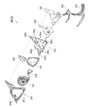
[1−2A.扉枠ベースユニット]
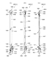
続いて、扉枠5における扉枠ベースユニット100について、主に図26乃至図30を参照して説明する。図26(A)は扉枠における扉枠ベースユニットの正面斜視図であり、(B)は扉枠における扉枠ベースユニットの背面斜視図である。また、図27は扉枠ベースユニットを分解して前から見た分解斜視図であり、図28は扉枠ベースユニットを分解して後ろから見た分解斜視図である。更に、図29は扉枠ベースユニットにおける扉枠ベース基板カバーと配線保持部材とを後から見た斜視図であり、図30は扉枠と本体枠とを電気的に接続するの配線の様子を拡大して示す斜視図である。
[1-2A. Door frame base unit]
Next, the door frame base unit 100 in the door frame 5 will be described mainly with reference to FIGS. 26 to 30. FIG. 26A is a front perspective view of the door frame base unit in the door frame, and FIG. 26B is a rear perspective view of the door frame base unit in the door frame. FIG. 27 is an exploded perspective view of the door frame base unit as seen from the front, and FIG. 28 is an exploded perspective view of the door frame base unit as seen from the rear. Further, FIG. 29 is a perspective view of the door frame base substrate cover and the wiring holding member in the door frame base unit as seen from the rear, and FIG. 30 shows the wiring state for electrically connecting the door frame and the main body frame. It is a perspective view which expands and shows.
本例の扉枠ベースユニット100は、図示するように、外形が縦長の矩形状に形成されると共に、前後方向に貫通し内周が縦長の略楕円形状に形成された遊技窓101を有する扉枠ベース本体110と、扉枠ベース本体110の前面で遊技窓101の上部中央に取付けられ上部装飾ユニットを固定するための上部ブラケット120と、扉枠ベース本体110の前面で遊技窓101の下端左右両外側に配置される一対のサイドスピーカ130と、サイドスピーカ130を扉枠べース本体110へ固定するためのスピーカブラケット132と、扉枠ベース本体110の前面で正面視右下隅部に取付けられハンドル装置500を支持するためのハンドルブラケット140と、を備えている。
As shown in the figure, the door frame base unit 100 of the present example is a door having a gaming window 101 whose outer shape is formed in a vertically long rectangular shape and penetrated in the front-rear direction and whose inner periphery is formed in a substantially elliptical shape having a vertically long shape. The frame base body 110, the upper bracket 120 for fixing the upper decorative unit attached to the upper center of the gaming window 101 on the front surface of the door frame base body 110, and the lower left and right sides of the gaming window 101 on the front surface of the door frame base body 110 A pair of side speakers 130 arranged on both outer sides, a speaker bracket 132 for fixing the side speakers 130 to the door frame base body 110, and the front side of the door frame base body 110 are attached to the lower right corner when viewed from the front. And a handle bracket 140 for supporting the handle device 500.
なお、扉枠ベースユニット100は、正面視で右側のサイドスピーカ130の外側には、サイドスピーカ130の側面と、右サイド装飾ユニット200等へ接続される配線136(図24を参照)の前側とを覆い扉枠ベース本体110の前面に取付けられるカバー部材134を更に備えている(図22及び図24等を参照)。このカバー部材134は、配線136をスピーカ取付部111の外周に沿って案内させることができると共に、サイドスピーカ130を取付ける際や取外す際に、配線136が邪魔にならないように配線136を保持することができるようになっている。
The door frame base unit 100 has a side surface of the side speaker 130 and a front side of a wiring 136 (see FIG. 24) connected to the right side decoration unit 200 and the like on the outside of the right side speaker 130 in front view. Is further provided with a cover member 134 that is attached to the front surface of the door frame base body 110 (see FIGS. 22 and 24). The cover member 134 can guide the wiring 136 along the outer periphery of the speaker mounting portion 111 and holds the wiring 136 so that the wiring 136 does not get in the way when the side speaker 130 is attached or removed. Can be done.
また、扉枠ベースユニット100は、扉枠ベース本体110の後側に固定される金属製で枠状の補強ユニット150と、扉枠ベース本体110の後面で遊技窓101の下部を被覆するように取付けられる防犯カバー180と、扉枠ベース本体110の後面で遊技窓101の外周の所定位置に回動可能に取付けられるガラスユニット係止部材190と、背面視で左右方向の中央より左側(開放側)に配置され遊技窓101の下端に沿って扉枠ベース本体110の後面に取付けられる発射カバー191と、発射カバー191の下側で扉枠ベース本体110の後面に取付けられハンドル装置500の回転位置検知センサ512と主制御基板4100との接続を中継するハンドル装置中継基板192と、ハンドル装置中継基板192の後側を被覆するハンドル装置中継基板カバー193と、左右方向の中央を挟んで発射カバー191やハンドル装置中継基板192等とは反対側(背面視で左右方向中央よりも右側(軸支側))に配置され扉枠ベース本体の後面に取付けられる扉枠ベース基板194と、扉枠ベース基板194の後側を被覆する扉枠ベース基板カバー195と、扉枠ベース基板カバー195の後面に回動可能に軸支され扉枠5側と本体枠3側とを接続する配線コード196の一部を保持する配線保持部材197と、を備えている。
Further, the door frame base unit 100 is configured so that the metal frame-shaped reinforcing unit 150 fixed to the rear side of the door frame base body 110 and the lower surface of the gaming window 101 are covered with the rear surface of the door frame base body 110. A security cover 180 to be attached, a glass unit locking member 190 rotatably attached to a predetermined position on the outer periphery of the gaming window 101 on the rear surface of the door frame base main body 110, and a left side (open side) from the center in the left-right direction in a rear view. ) And a launch cover 191 attached to the rear face of the door frame base body 110 along the lower end of the gaming window 101, and a rotational position of the handle device 500 attached to the rear face of the door frame base body 110 below the launch cover 191. The handle device relay board 192 that relays the connection between the detection sensor 512 and the main control board 4100 and the rear side of the handle device relay board 192 are covered. The door frame is disposed on the opposite side of the middle device relay board cover 193 and the launch cover 191 and the handle device relay board 192 with the center in the left-right direction (right side of the left-right center (back side) in the rear view). A door frame base substrate 194 attached to the rear surface of the base main body, a door frame base substrate cover 195 covering the rear side of the door frame base substrate 194, and a door pivotally supported on the rear surface of the door frame base substrate cover 195. A wiring holding member 197 that holds a part of the wiring cord 196 that connects the frame 5 side and the main body frame 3 side is provided.
本例の扉枠ベースユニット100は、合成樹脂からなる矩形状の扉枠ベース本体110の後側に、金属板金をリベット等で組立てた補強ユニット150が固定されることで、全体の剛性が高められていると共に、各装飾ユニット200,240,280や皿ユニット300等を充分に支持することができる強度を有している。
The door frame base unit 100 of the present example has an overall rigidity increased by fixing a reinforcing unit 150 in which metal sheet metal is assembled with rivets or the like to the rear side of a rectangular door frame base body 110 made of synthetic resin. In addition, it has a strength capable of sufficiently supporting the decorative units 200, 240, 280, the dish unit 300, and the like.
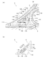
この扉枠ベースユニット100における扉枠ベース基板194は、サイドスピーカ130や左右のサイド装飾ユニット200,240の上部スピーカ222,262と接続されると共に、後述する遊技盤4に備えられた周辺制御部4140と接続されており、周辺制御部4140から送られた音響信号を増幅して各スピーカ130へ出力する増幅回路を備えている。なお、本例では、各装飾ユニット200,240,280及び皿ユニット300や操作ユニット400に備えられた各装飾基板430,432、操作ユニット400に備えられたダイヤル駆動モータ414やセンサ432a,432b,432c、ハンドル装置中継基板192、皿ユニット300の貸球ユニット360等と、払出制御基板4110や周辺制御部4140等とを接続する配線コード196が、扉枠ベース基板194の背面視で右側(軸支側)の位置に集約して束ねられた上で、詳細は後述するが、配線保持部材197に保持されて後方へ延出し、本体枠3の主側中継端子板880や周辺側中継端子板882に接続されるようになっている(図1及び図30を参照)。
The door frame base board 194 in the door frame base unit 100 is connected to the side speakers 130 and the upper speakers 222 and 262 of the left and right side decoration units 200 and 240, and a peripheral control unit provided in the game board 4 to be described later. 4, and an amplification circuit that amplifies the acoustic signal sent from the peripheral control unit 4140 and outputs the amplified signal to each speaker 130. In this example, each decoration unit 200, 240, 280, each decorative board 430, 432 provided in the dish unit 300 or the operation unit 400, dial driving motor 414 or sensor 432a, 432b provided in the operation unit 400, 432c, the handle device relay board 192, the ball rental unit 360 of the dish unit 300, and the wiring cord 196 that connects the payout control board 4110, the peripheral control unit 4140, etc. As will be described in detail later, the main side relay terminal plate 880 and the peripheral side relay terminal plate of the main body frame 3 are extended to the rear by being held by the wiring holding member 197. 882 (see FIGS. 1 and 30).
本例の扉枠ベースユニット100における扉枠ベース本体110は、図27及び図28等に示すように、合成樹脂によって縦長の額縁状に形成されており、前後方向に貫通し内形が縦長で略楕円形状の遊技窓101が全体的に上方へオフセットするような形態で形成されている。この遊技窓101は、図示するように、左右側及び上側の内周縁が連続した滑らかな曲線状に形成されているのに対して、下側の内周縁は左右へ延びた直線状に形成されている。また、扉枠ベース本体110における遊技窓101の下側の内周縁には、軸支側(正面視で左側)にファールカバーユニット540の第一球出口544aを挿通可能な方形状101aの切欠部が形成されている。この扉枠ベース本体110は、遊技窓101によって形成される上辺、及び左右の側辺の幅が、後述する補強ユニット150の上側補強板金151、軸支側補強板金152、及び開放側補強板金153の幅と略同じ幅とされており、正面視における扉枠ベース本体の大きさに対して、遊技窓101が可及的に大きく形成されている。従って、扉枠5の後側に配置される遊技盤4のより広い範囲を遊技者側から視認できるようになっており、従来のパチンコ機よりも広い遊技領域1100を容易に形成することができるようになっている。
The door frame base main body 110 in the door frame base unit 100 of this example is formed in a vertically long frame shape by synthetic resin as shown in FIGS. The game window 101 having a substantially elliptical shape is formed so as to be offset upward as a whole. As shown in the figure, the gaming window 101 is formed in a smooth curved shape in which the left and right side and upper inner peripheral edges are continuous, whereas the lower inner peripheral edge is formed in a straight line extending to the left and right. ing. Further, on the inner peripheral edge of the lower side of the game window 101 in the door frame base body 110, a cutout portion of a rectangular shape 101a into which the first ball outlet 544a of the foul cover unit 540 can be inserted on the shaft support side (left side in front view). Is formed. The door frame base body 110 has an upper side formed by the gaming window 101 and widths of the left and right sides of an upper reinforcing sheet metal 151, a pivot supporting side reinforcing sheet metal 152, and an open side reinforcing sheet metal 153 of a reinforcing unit 150 described later. The gaming window 101 is formed as large as possible with respect to the size of the door frame base body in a front view. Accordingly, a wider range of the game board 4 arranged on the rear side of the door frame 5 can be viewed from the player side, and a game area 1100 wider than the conventional pachinko machine can be easily formed. It is like that.
この扉枠ベース本体110は、遊技窓101の他に、遊技窓101の下辺の左右両外側に配置されサイドスピーカ130を取付固定するためのスピーカ取付部111と、球送りユニット580を取付固定するための球送りユニット取付凹部112(図28を参照)と、球送りユニット取付凹部112の所定位置で前後方向に貫通し皿ユニット300の上皿301に貯留された遊技球を球送りユニット580へ供給するための球送り開口113と、正面視で右下隅部に配置され前方へ膨出した前面の右側(開放側)端が後退するように斜めに傾斜しハンドルブラケット140を取付けるためのハンドル取付部114と、ハンドル取付部114の所定位置で前後方向へ貫通しハンドル装置500からの配線が通過可能な配線通過口115と、ハンドル取付部114の上側で前方へ向かって短く延びた筒状に形成され後述するシリンダ錠1010が挿通可能な錠穴116と、を備えている。
In addition to the gaming window 101, the door frame base body 110 is disposed on both the left and right outer sides of the lower side of the gaming window 101, and attaches and fixes the ball feeding unit 580 and the speaker mounting portion 111 for mounting and fixing the side speaker 130. The ball feeding unit mounting recess 112 (see FIG. 28) and the game ball penetrating in the front-rear direction at a predetermined position of the ball feeding unit mounting recess 112 and stored in the upper plate 301 of the tray unit 300 are transferred to the ball feeding unit 580. A ball feed opening 113 for supply and a handle attachment for attaching the handle bracket 140 inclined obliquely so that the right side (open side) end of the front surface which is arranged in the lower right corner portion and bulges forward in the front view is retracted Part 114, a wiring passage port 115 that penetrates in the front-rear direction at a predetermined position of the handle attachment part 114 and allows the wiring from the handle device 500 to pass through, Cylinder lock 1010 to be described later is formed in a cylindrical shape extending short toward the front in the upper Le mounting portion 114 is provided with a Joana 116, which can be inserted.
また、扉枠ベース本体110は、図28に示すように、球送りユニット取付凹部112に下側にハンドル装置中継基板192を取付けるための中継基板取付部117と、背面視で扉枠ベース本体の下部右側(軸支側)に配置され扉枠ベース基板194を取付けるための基板取付部118と、遊技窓101の下端の背面視左側(開放側)でスピーカ取付部111よりも中央寄りの配置から後方へ突出し防犯カバー180の装着弾性片185を装着するための防犯カバー装着部119と、扉枠ベース本体110は、その後側に、遊技窓101の内周に略沿って前側へ凹みガラスユニット590の前面外周縁が当接可能なガラスユニット支持段部110aと、遊技窓101の外周の所定位置から後方へ突出しガラスユニット係止部材190を回動可能に支持するための四つの係止部材取付部110bと、を更に備えている。
Further, as shown in FIG. 28, the door frame base main body 110 includes a relay board mounting portion 117 for mounting the handle device relay board 192 on the lower side of the ball feed unit mounting recess 112, and a door frame base main body in the rear view. A board mounting part 118 for mounting the door frame base board 194 disposed on the lower right side (axis support side), and an arrangement closer to the center than the speaker mounting part 111 on the left side (open side) in the rear view of the lower end of the gaming window 101 The security cover mounting portion 119 for protruding backward and mounting the mounting elastic piece 185 of the security cover 180 and the door frame base body 110 are recessed to the front side substantially along the inner periphery of the gaming window 101 on the rear side. The glass unit support step 110a with which the outer periphery of the front surface can abut and the glass unit locking member 190 can be rotated by protruding backward from a predetermined position on the outer periphery of the gaming window 101. Further comprises a, and four of the locking member mounting portion 110b for supporting the.
更に、扉枠ベース本体110の後側には、その下辺から後方へ所定量突出する扉枠突片110cを備えており、この扉枠突片110cは、後述する本体枠3の係合溝603内に挿入されるようになっている。これにより、扉枠5が本体枠3に対して位置決め係止することができると共に、扉枠5と本体枠3との下辺の隙間からピアノ線等の不正な工具をパチンコ機1内に挿入しようとしても、係合溝603と係合した扉枠突片110cによって工具の侵入を阻止することができ、パチンコ機1の防犯機能が高められている。また、扉枠ベース本体110の後側には、背面視で錠穴116よりもやや右下の位置から後方へ突出し本体枠3の嵌合溝612と嵌合する位置決め突起110dを、備えており、この位置決め突起110dが嵌合溝612と嵌合することで、扉枠5と本体枠3とが正しい位置に位置決めされるようになっている。
Further, the rear side of the door frame base body 110 is provided with a door frame protruding piece 110c protruding a predetermined amount rearward from the lower side thereof, and the door frame protruding piece 110c is an engagement groove 603 of the main body frame 3 described later. It is designed to be inserted inside. As a result, the door frame 5 can be positioned and locked with respect to the main body frame 3, and an unauthorized tool such as a piano wire is inserted into the pachinko machine 1 from the gap between the lower side of the door frame 5 and the main body frame 3. Even so, the door frame protrusion 110c engaged with the engagement groove 603 can prevent the tool from entering, and the security function of the pachinko machine 1 is enhanced. The rear side of the door frame base body 110 is provided with a positioning projection 110d that protrudes rearward from a position slightly lower right than the lock hole 116 in rear view and engages with the fitting groove 612 of the body frame 3. The positioning projection 110d is fitted into the fitting groove 612 so that the door frame 5 and the main body frame 3 are positioned at correct positions.
また、扉枠ベース本体110は、図27に示すように、その前面に、装飾ユニット200,240,280や皿ユニット300等を固定するための前方へ突出した複数の取付ボス110eが備えられていると共に、上部ブラケット120、ハンドルブラケット140等を取付けるための取付穴が適宜位置に多数形成されている。また、扉枠ベース本体110は、サイドスピーカ130を取付けるスピーカブラケット132を取付けるための取付部110g(図24を参照)や、サイドスピーカカバー290を取付けるための取付孔110h(図18、図24及び図25等を参照)が、適宜位置に夫々形成されている。
Further, as shown in FIG. 27, the door frame base main body 110 is provided with a plurality of mounting bosses 110e projecting forward for fixing the decorative units 200, 240, 280, the dish unit 300, and the like. In addition, a large number of mounting holes for mounting the upper bracket 120, the handle bracket 140 and the like are formed at appropriate positions. Further, the door frame base body 110 has an attachment portion 110g (see FIG. 24) for attaching the speaker bracket 132 for attaching the side speaker 130, and an attachment hole 110h (FIGS. 18, 24, and 24) for attaching the side speaker cover 290. Are formed at appropriate positions.
なお、サイドスピーカカバー290では、図25に示すように、左右夫々一つずつ、ガラスユニット590が後側から嵌め込まれるガラスユニット支持段部110aを貫通するように配置されており、扉枠ベース本体110(扉枠5)からガラスユニット590を取外した状態で、取付孔110hを介して所定のビスにより脱着することができるようになっている。更に、サイドスピーカカバー290を取付けるための取付孔110hは、図18に示すように、扉枠ベース本体110に防犯カバー180を固定することで後側が被覆されるようになっている。従って、サイドスピーカカバー290を取外すには、まず始めに防犯カバー180とガラスユニット590とを、扉枠ベース本体110から取外さなければならないようになっている。これにより、サイドスピーカカバー290の取外しに若干時間がかかるようにすることで不正行為等を行おうとする者に対して取外作業を手間取らせることができると共に、比較的大きなガラスユニット590を取外すことで取外し作業を目立たせることができ、サイドスピーカ130に対する盗難行為や、遊技領域1100内等に対する不正行為等を躊躇させて、不正行為等に対する抑止力(安全性)を高めることができるようになっている。
In the side speaker cover 290, as shown in FIG. 25, the left and right ones are arranged so as to pass through the glass unit support stepped portions 110a into which the glass units 590 are fitted from the rear side. In a state where the glass unit 590 is removed from the 110 (door frame 5), the glass unit 590 can be detached with a predetermined screw through the mounting hole 110h. Furthermore, as shown in FIG. 18, the mounting hole 110 h for mounting the side speaker cover 290 is configured such that the rear side is covered by fixing the security cover 180 to the door frame base main body 110. Therefore, in order to remove the side speaker cover 290, first, the security cover 180 and the glass unit 590 must be removed from the door frame base body 110. Accordingly, it is possible to take time for removing the side speaker cover 290 to allow a person who performs an illegal act to remove the relatively large glass unit 590. The removal work can be made conspicuous, and the deterrence (safety) against fraud etc. can be enhanced by deceiving theft acts on the side speakers 130 and the fraudulent acts on the game area 1100 etc. It has become.
また、扉枠ベース本体110には、球送りユニット取付凹部112と基板取付部118との間で、後述する皿ユニット300の皿ユニットベース310における下皿球供給口310g及びファールカバーユニット540の第二球出口544bと対応する位置に、前後方向に貫通する矩形状の球通過口110fを備えている。
In addition, the door frame base main body 110 includes a lower dish ball supply port 310g and a foul cover unit 540 in the dish unit base 310 of the dish unit 300, which will be described later, between the ball feeding unit mounting recess 112 and the substrate mounting part 118. A rectangular ball passage opening 110f penetrating in the front-rear direction is provided at a position corresponding to the two-ball outlet 544b.
次に、扉枠ベースユニット100における上部ブラケット120は、扉枠ベース本体110の前面上部中央に固定されるものであり、詳細な図示は省略するが、扉枠ベースユニット100に取付けられた左右のサイド装飾ユニット200,240の間に形成される上部の隙間を隠蔽すると共に、左右両端が夫々サイド装飾ユニット200,240によって支持されるようになっている。また、上部ブラケット120は、その先端の一部が上部装飾ユニット280内へ挿入されるようになっており、扉枠5が組立てられた状態では、上部装飾ユニット280を上側から支持することができるようになっている。
Next, the upper bracket 120 in the door frame base unit 100 is fixed to the upper center of the front surface of the door frame base main body 110, and although detailed illustration is omitted, the left and right attached to the door frame base unit 100 are left and right. The upper gap formed between the side decoration units 200 and 240 is concealed, and both left and right ends are supported by the side decoration units 200 and 240, respectively. The upper bracket 120 is partially inserted into the upper decorative unit 280 so that the upper decorative unit 280 can be supported from above when the door frame 5 is assembled. It is like that.
また、扉枠ベースユニット100における一対のサイドスピーカ130は、詳細な図示は省略するが、その中心軸の交点が正面視で遊技領域1100の中央から前方へ所定距離(例えば、0.2m〜1.5m)の位置となるように斜めに固定されており、パチンコ機1の前に着座した遊技者に対して最も効率良く音が届くようになっている。また、このサイドスピーカ130は、主に中高音域の音を出力するようになっていると共に、パチンコ機1に対して、可及的に左右方向へ離反した位置に配置されており、左右のサイドスピーカ130から関連した異なる音を出力させることで、ステレオ感の高い音を出力することができるようになっている。
The pair of side speakers 130 in the door frame base unit 100 is not shown in detail, but the intersection of the central axes is a predetermined distance from the center of the game area 1100 to the front in front view (for example, 0.2 m to 1). .5 m), the sound is delivered most efficiently to the player seated in front of the pachinko machine 1. In addition, the side speaker 130 mainly outputs middle and high range sounds, and is disposed at a position as far away from the pachinko machine 1 as possible in the left-right direction. By outputting different related sounds from the side speaker 130, it is possible to output a sound with a high stereo feeling.
これらサイドスピーカ130は、その外周が、前側に配置された略円環状のスピーカブラケット132と、後側に配置された扉枠ベース本体110のスピーカ取付部111とによって挟持されることで、扉枠ベース本体110に取付けられるようになっている。なお、スピーカブラケット132は、所定のビスによって、前側から扉枠ベース本体110の取付部110gに取付けられるようになっている。
The outer periphery of these side speakers 130 is sandwiched between a substantially annular speaker bracket 132 disposed on the front side and a speaker mounting portion 111 of the door frame base body 110 disposed on the rear side, so that the door frame It can be attached to the base body 110. The speaker bracket 132 is attached to the attachment portion 110g of the door frame base body 110 from the front side with a predetermined screw.
また、扉枠ベースユニット100における扉枠ベース基板カバー195は、図27乃至図29等に示すように、前側が開放された薄い箱状に形成されていると共に、後側の後面に、上下方向の中央よりもやや下寄りの位置で前方へ窪んだ段部195aを備えている。この扉枠ベース基板カバー195の段部195aに、配線保持部材197が回動可能に取付けられている。
In addition, the door frame base substrate cover 195 in the door frame base unit 100 is formed in a thin box shape with the front side opened as shown in FIGS. A step portion 195a that is recessed forward is provided at a position slightly below the center. A wiring holding member 197 is rotatably attached to the step portion 195a of the door frame base substrate cover 195.
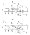
一方、扉枠ベースユニット100における配線保持部材197は、図29及び図30等に示すように、横方向へ長く延びた板状に形成されていると共に、断面がI字状に形成されており、比較的、硬質の合成樹脂によって形成されている。また、配線保持部材197は、図示するように、上下両端に長手方向へ沿って所定間隔で複数(本例では、上下に夫々三つずつ)の保持孔197aを備えている。この配線保持部材197は、扉枠5を組立てた状態で扉枠5が本体枠3に軸支される側の端部が、扉枠ベース基板カバー195における後面の段部195aに、上下方向へ延びた軸周りに回動可能に軸支されており、詳細な図示は省略するが、配線保持部材197の自由端側が扉枠ベース基板カバー195側へ回動することで、配線保持部材197が扉枠ベース基板カバー195の段部195a内へ収容することができるようになっている。
On the other hand, the wiring holding member 197 in the door frame base unit 100 is formed in a plate shape extending in the lateral direction as shown in FIGS. 29 and 30, and the cross section is formed in an I-shape. It is formed of a relatively hard synthetic resin. Further, as shown in the figure, the wiring holding member 197 includes a plurality of holding holes 197a (three in the upper and lower parts in this example) at predetermined intervals along the longitudinal direction at both upper and lower ends. The wiring holding member 197 has an end portion on the side where the door frame 5 is pivotally supported by the main body frame 3 in a state where the door frame 5 is assembled, and a step 195 a on the rear surface of the door frame base substrate cover 195 in the vertical direction. Although the detailed illustration is omitted, the free end side of the wiring holding member 197 rotates to the door frame base substrate cover 195 side, so that the wiring holding member 197 is rotated. The door frame base substrate cover 195 can be accommodated in the stepped portion 195a.
この配線保持部材197は、その後面側に扉枠5と本体枠3とを電気的に接続するための配線コード196を沿わせた状態で、上下で対になった保持孔197aに所定の結束バンド198を挿通させて、その結束バンド198により配線保持部材197ごと配線コード196を締付けることで、配線コード196を保持することができるようになっている(図1及び図30を参照)。
This wiring holding member 197 has a predetermined bundling in a holding hole 197a which is paired up and down with the wiring cord 196 for electrically connecting the door frame 5 and the main body frame 3 along the rear surface side. The wiring cord 196 can be held by inserting the band 198 and tightening the wiring cord 196 together with the wiring holding member 197 by the binding band 198 (see FIGS. 1 and 30).
本例の配線保持部材197は、本体枠3に対して扉枠5を閉じる方向へ回動させると、配線保持部材197の自由端側が、配線コード196における自由端側から本体枠3へ延びた部分により前方へ押されて扉枠ベース基板カバー195側へ近付く方向へ回動することとなる。これにより、扉枠5が閉まるに従って、配線保持部材197の自由端側が扉枠ベース基板カバー195へ接近すると共に、配線保持部材197の自由端から本体枠3側へ延びだした配線コード196が自由端付近で折れ曲りが大きく(鋭く)なる。そして、本体枠3に対して扉枠5が閉じられた状態となると、配線コード196が配線保持部材197の自由端側で横方向へ二つに折り畳まれたような状態となる。
When the wiring holding member 197 of this example is rotated in the direction in which the door frame 5 is closed with respect to the main body frame 3, the free end side of the wiring holding member 197 extends from the free end side of the wiring cord 196 to the main body frame 3. It will be pushed forward by the part and will turn in the direction approaching the door frame base substrate cover 195 side. Thereby, as the door frame 5 is closed, the free end side of the wiring holding member 197 approaches the door frame base substrate cover 195, and the wiring cord 196 extending from the free end of the wiring holding member 197 to the main body frame 3 side is free. The bend becomes large (sharp) near the edge. When the door frame 5 is closed with respect to the main body frame 3, the wiring cord 196 is folded in two laterally on the free end side of the wiring holding member 197.
一方、本体枠3に対して閉じられた扉枠5を開ける場合では、本体枠3と扉枠5とが相対的に遠ざかることとなるので、本体枠3側に接続された配線コード196によって配線保持部材197の自由端側が後方へ引っ張られることとなり、自由端側が扉枠ベース基板カバー195から遠ざかる方向(本体枠3の方向)へ移動するように配線保持部材197がスムーズに回動する。これにより、配線保持部材197の自由端側で折り畳まれた配線コード196が真直ぐに延びるように展開し、配線コード196によって阻害されること無く扉枠5を開くことができるようになっている。
On the other hand, when the door frame 5 closed with respect to the main body frame 3 is opened, the main body frame 3 and the door frame 5 are relatively distant from each other, so that wiring is performed by the wiring cord 196 connected to the main body frame 3 side. The free end side of the holding member 197 is pulled rearward, and the wiring holding member 197 rotates smoothly so that the free end side moves in a direction away from the door frame base substrate cover 195 (direction of the main body frame 3). Thus, the wiring cord 196 folded on the free end side of the wiring holding member 197 is unfolded so as to extend straight, and the door frame 5 can be opened without being obstructed by the wiring cord 196.
このように、本例によると、配線保持部材197における扉枠5が軸支された側と同じ側の端部を、自由端側が本体枠3側へ移動するように扉枠ベース基板カバー195の後面に回動可能に軸支させると共に、扉枠5と本体枠3とを電気的に接続する配線コード196の一部が上下方向へ移動しないように保持するようにしているので、本体枠3に対して扉枠5を開閉させる際に、配線保持部材197の自由端側で配線コード196を横方向へ折り畳んだり、展開したりすることができ、扉枠5の開閉時に配線コード196が引っ掛かったり挟まれたりして不具合(配線コード196の断線、接続コネクタの外れ、等)が発生するのを防止することができるようになっている。
As described above, according to this example, the end of the wiring frame holding member 197 on the same side as the side on which the door frame 5 is pivotally supported, the door frame base substrate cover 195 is moved so that the free end side moves to the main body frame 3 side. Since it is pivotally supported on the rear surface and a part of the wiring cord 196 that electrically connects the door frame 5 and the main body frame 3 is held so as not to move in the vertical direction, the main body frame 3 When the door frame 5 is opened and closed, the wiring cord 196 can be folded or unfolded laterally on the free end side of the wiring holding member 197, and the wiring cord 196 is caught when the door frame 5 is opened and closed. It is possible to prevent the occurrence of malfunctions (such as disconnection of the wiring cord 196, disconnection of the connection connector, etc.) due to pinching.
また、本例によると、配線保持部材197を比較的硬質で剛性の高い合成樹脂によって形成するようにしているので、扉枠5の開閉時に、配線コード196を介して力が作用しても、上下方向へブレ難くすることができ、配線コード196を確実に横方向へ折り畳んで不具合の発生を防止することができるようになっている。
Further, according to this example, since the wiring holding member 197 is formed of a relatively hard and highly rigid synthetic resin, even when a force acts through the wiring cord 196 when the door frame 5 is opened and closed, It is possible to prevent blurring in the vertical direction, and the wiring cord 196 can be reliably folded in the horizontal direction to prevent occurrence of problems.
更に、上述したように、本体枠3に対して扉枠5を開閉させると、配線保持部材197によって本体枠3と扉枠5との間に橋が掛けられたような状態となり、配線196の一部が配線保持部材197によって架橋された状態となるので、扉枠5を開閉させても配線196が垂れ下がるのを防止することが可能となり、配線196が垂れ下がることで他の部材に引っ掛かって断線したり扉枠5を閉じることができなくなったりする不具合が発生するのを防止することができ、本体側電気機器としての主制御基板4100、周辺制御部4140、払出制御基板4110等、と扉側電気機器としての各装飾基板214,216,254,256,286,320,430,432、スピーカ130,222,262、貸球ユニット360、ハンドル装置500等、とを接続する配線196に不具合が発生するのを可及的に低減させることが可能なパチンコ機1を提供することができる。
Further, as described above, when the door frame 5 is opened and closed with respect to the main body frame 3, a bridge is hung between the main body frame 3 and the door frame 5 by the wiring holding member 197. Since a part is bridged by the wiring holding member 197, it is possible to prevent the wiring 196 from drooping even when the door frame 5 is opened and closed, and when the wiring 196 droops, it is caught by another member and disconnected. Or the door frame 5 cannot be closed, and the main control board 4100, the peripheral control unit 4140, the payout control board 4110, and the like as the main body side electric devices are connected to the door side. Decorative boards 214, 216, 254, 256, 286, 320, 430, 432, speakers 130, 222, 262, a ball rental unit 360, and a handle as electric devices Location 500, etc., capital can provide pachinko machine 1 capable of malfunction in the wiring 196 to be connected to reduce the occurrence as much as possible.
また、配線196の一部を回動可能な配線保持部材197で保持するようにしており、扉枠5を開ける時に、配線196が無理に引っ張られても、配線保持部材197が回動することでその力を逃がすことができるので、配線196が引っ張られるのを防止することができ、配線196が引っ張られて断線したり接続コネクタが外れたりするような不具合が発生するのを防止することができる。また、配線保持部材197によって配線196の一部を保持しており、配線196は配線保持部材197の回動に伴って単に部分的に曲がるだけなので、従来のもの(例えば、特開2009−213675)のように配線196が摺動することは無く、配線196が擦れて漏電や断線等の不具合が発生するのを防止することができる。
Further, a part of the wiring 196 is held by a rotatable wiring holding member 197, and the wiring holding member 197 rotates even if the wiring 196 is forcibly pulled when the door frame 5 is opened. Therefore, it is possible to prevent the wiring 196 from being pulled, and to prevent a problem that the wiring 196 is pulled and disconnected or the connection connector is disconnected. it can. In addition, a part of the wiring 196 is held by the wiring holding member 197, and the wiring 196 is only partially bent as the wiring holding member 197 rotates, so that the conventional one (for example, Japanese Patent Application Laid-Open No. 2009-213675). ), The wiring 196 does not slide, and it is possible to prevent the wiring 196 from being rubbed and causing problems such as leakage or disconnection.
更に、配線保持部材197では、長手方向へ所定間隔で複数配置された貫通する保持孔197aに結束バンド198を挿通し、その結束バンド198によって配線196を保持するようにしているので、配線196を保持した結束バンド198が保持孔197aによって配線保持部材197の長手方向へ移動(スライド)するのを防止することができ、配線保持部材197から結束バンド198ごと配線196が脱落するのを確実に防止することができる。
Further, in the wiring holding member 197, the binding band 198 is inserted into the holding holes 197 a that are arranged at a predetermined interval in the longitudinal direction, and the wiring 196 is held by the binding band 198. It is possible to prevent the held binding band 198 from moving (sliding) in the longitudinal direction of the wiring holding member 197 through the holding hole 197a, and to reliably prevent the wiring 196 from dropping together with the binding band 198 from the wiring holding member 197. can do.
また、本体枠3や扉枠5から配線196が延びだす位置を、扉枠5を軸支した側辺から離れた位置に配置しても、上述したように、配線保持部材197によって配線196をガイド(案内)して扉枠5を開閉する際に配線196が垂れ下がるのを良好に防止することができるので、扉枠5おける軸支された側辺側の強度・剛性を高めた本体枠3や扉枠5とすることができ、不正行為に対する防犯性の高いパチンコ機1とすることができる。
Even if the position where the wiring 196 extends from the main body frame 3 or the door frame 5 is arranged at a position away from the side where the door frame 5 is pivotally supported, the wiring 196 is connected by the wiring holding member 197 as described above. Since it is possible to satisfactorily prevent the wiring 196 from drooping when the door frame 5 is opened and closed by guiding, the main body frame 3 having increased strength and rigidity on the side of the door frame 5 that is pivotally supported. And the door frame 5, and the pachinko machine 1 with high security against fraudulent acts can be obtained.
更に、配線保持部材197に、長手方向に対して直角方向両端から少なくとも配線196が沿う側へ突出した突条を備えるようにしているので、一対の突条と配線保持部材197の板面によって配線196の三方を囲むことができ、配線保持部材197に沿って配線196を保持し易くすることができる。また、配線保持部材197に突条を備えているので、板状の配線保持部材197の曲げ剛性を高めることができ、扉枠5を開閉する際に配線保持部材197が撓むのを防止して、良好な状態で扉枠5を開閉させることができる。
Further, since the wiring holding member 197 is provided with protrusions protruding at least from the both ends in the direction perpendicular to the longitudinal direction to the side along which the wiring 196 is located, the wiring is formed by the pair of protrusions and the plate surface of the wiring holding member 197. 196 can be surrounded, and the wiring 196 can be easily held along the wiring holding member 197. Further, since the wiring holding member 197 is provided with a protrusion, the bending rigidity of the plate-like wiring holding member 197 can be increased, and the wiring holding member 197 is prevented from being bent when the door frame 5 is opened and closed. Thus, the door frame 5 can be opened and closed in a good state.
また、配線保持部材197の基端から先端までの長さを、扉枠5の軸心から基端の軸心までの距離と略同じ長さとすると共に、配線196における本体枠3の延出した所定位置を、本体枠3に対して扉枠5を閉じた状態で、配線保持部材197の先端よりも扉枠5の軸心側の位置としており、扉枠5の軸心と、配線保持部材197の軸心と、配線保持部材197の先端と、本体枠3における配線196が延出した位置とで、パンタグラフ状のリンクが形成されることとなるので、扉枠5を開閉する時の配線保持部材197や配線196等の動きをスムーズにすることができ、開閉作業を行い易くすることができると共に、配線196等に無理な力が作用するのを低減させて断線等の不具合が発生するのを防止することができる。また、パンタグラフ状のリンクを形成するようにしており、扉枠5を閉じる時に、配線196における配線保持部材197の先端から延出した部位が、配線保持部材197と沿うように先端側で折返されるので、扉枠5を閉じた状態では配線196を折り畳んでコンパクトに纏めることができ、配線保持部材197や配線196に係るスペースを小さくすることができる。
In addition, the length from the base end to the tip end of the wiring holding member 197 is substantially the same as the distance from the axis of the door frame 5 to the base of the base end, and the main body frame 3 extends in the wiring 196. The predetermined position is a position closer to the axial center side of the door frame 5 than the tip of the wiring holding member 197 in a state where the door frame 5 is closed with respect to the main body frame 3, and the axial center of the door frame 5 and the wiring holding member Since a pantograph-like link is formed by the axis of 197, the tip of the wiring holding member 197, and the position where the wiring 196 extends in the main body frame 3, wiring when opening and closing the door frame 5 The movement of the holding member 197, the wiring 196, etc. can be made smooth, the opening / closing operation can be facilitated, and an unreasonable force acting on the wiring 196, etc. can be reduced to cause problems such as disconnection. Can be prevented. Further, a pantograph-like link is formed, and when the door frame 5 is closed, a portion of the wiring 196 that extends from the front end of the wiring holding member 197 is folded back on the front end side along the wiring holding member 197. Therefore, when the door frame 5 is closed, the wiring 196 can be folded and gathered compactly, and the space related to the wiring holding member 197 and the wiring 196 can be reduced.
また、配線保持部材197を軸支した扉枠5の扉枠ベース基板カバー195に、本体枠3に対して扉枠5を閉じた状態で、本体枠3側へ向かって開口するように凹み、配線保持部材197を収納可能な段部195aを備えるようにしており、本体枠3に対して扉枠5を閉じた状態とすると、配線保持部材197が扉枠ベース基板カバー195に備えられた段部195a内へ収納されるので、扉枠5側から本体枠3側への配線保持部材197の突出を殆ど無くすことができ、扉枠5を閉じ易くすることができると共に、配線保持部材197や配線196をコンパクトに纏めることができ、配線196が他の部材に引っ掛かるのを抑制して不具合が発生するのを防止することができる。
In addition, the door frame base substrate cover 195 of the door frame 5 that pivotally supports the wiring holding member 197 is recessed so as to open toward the main body frame 3 with the door frame 5 being closed with respect to the main body frame 3. When the door frame 5 is closed with respect to the main body frame 3, the step 195 a that can store the wiring holding member 197 is provided, and the wiring frame holding member 197 is provided on the door frame base substrate cover 195. Since it is housed in the portion 195a, the protrusion of the wiring holding member 197 from the door frame 5 side to the main body frame 3 side can be almost eliminated, the door frame 5 can be easily closed, and the wiring holding member 197 or The wirings 196 can be gathered in a compact manner, and the wiring 196 can be prevented from being caught by other members, thereby preventing a problem from occurring.
更に、配線196を、本体枠3に対して扉枠5を閉じた状態で、配線保持部材197における本体枠3側を向いた面に沿って保持させるようにしており、本体枠3に対して扉枠5を閉じた状態とした時に、配線保持部材197を扉枠5側(扉枠ベース基板カバー195側)へ可及的に近づけることができるので、これによっても、扉枠5からの配線保持部材197の突出を少なくすることができ、扉枠5を閉じ易くすることができると共に、配線保持部材197や配線196に係るスペースを可及的に小さくすることができる。
Further, the wiring 196 is held along the surface of the wiring holding member 197 facing the main body frame 3 side with the door frame 5 closed with respect to the main body frame 3. When the door frame 5 is closed, the wiring holding member 197 can be brought as close as possible to the door frame 5 side (door frame base substrate cover 195 side). The protrusion of the holding member 197 can be reduced, the door frame 5 can be easily closed, and the space related to the wiring holding member 197 and the wiring 196 can be made as small as possible.
また、配線保持部材197を移動(開閉)する扉枠5側に備えているので、扉枠5を開閉させる慣性力や衝撃力等によって配線保持部材197を回動させ易くすることができ、上述した作用効果を確実に奏することができる。また、配線保持部材197を扉枠5に備えており、本体枠3に配線保持部材197を備えるためのスペースを確保する必要が無いので、相対的に本体枠3における遊技盤4を保持するスペースを大きくしてより大きな遊技領域1100を有した遊技盤4を保持させることができ、大型の遊技盤4を有して遊技者の関心を強く引付けることが可能なパチンコ機1とすることができる。
Further, since the wiring holding member 197 is provided on the side of the door frame 5 that moves (opens and closes), the wiring holding member 197 can be easily rotated by an inertial force or an impact force that opens and closes the door frame 5. It is possible to reliably achieve the function and effect. Moreover, since the wiring holding member 197 is provided in the door frame 5 and it is not necessary to secure a space for providing the wiring holding member 197 in the main body frame 3, a space for relatively holding the game board 4 in the main body frame 3. The pachinko machine 1 which can hold the game board 4 having a larger game area 1100 by enlarging the game area 1 and can attract the player's interest strongly by having the large game board 4 is provided. it can.
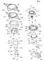
更に、扉枠ベースユニット100におけるハンドルブラケット140は、図27及び図28等に示すように、前後方向へ延びた円筒状の筒部141と、筒部141の後端から筒部141の軸に対して直角方向外方へ延びた円環状のフランジ部142と、筒部141内に突出し筒部141の周方向に対して不等間隔に配置された複数(本例では三つ)の突条143と、筒部141の外周面とフランジ部142の前面とを繋ぎ筒部141の周方向に対して複数配置された補強リブ144と、を備えている。このハンドルブラケット140は、フランジ部142の後面を、扉枠ベース本体110におけるハンドル取付部114の前面に当接させた状態で、所定のビスによってハンドル取付部114に取付けられるようになっており、図示は省略するが、ハンドル取付部114に取付けた状態で、筒部141の軸が配線通過口115と略一致するようになっている。
Further, the handle bracket 140 in the door frame base unit 100 includes a cylindrical tube portion 141 extending in the front-rear direction and a shaft of the tube portion 141 from the rear end of the tube portion 141 as shown in FIGS. An annular flange portion 142 extending outward in a right angle direction, and a plurality of (three in this example) ridges protruding into the cylindrical portion 141 and arranged at unequal intervals with respect to the circumferential direction of the cylindrical portion 141. 143, and a plurality of reinforcing ribs 144 that connect the outer peripheral surface of the cylindrical portion 141 and the front surface of the flange portion 142 with respect to the circumferential direction of the cylindrical portion 141. The handle bracket 140 is attached to the handle attachment portion 114 with a predetermined screw in a state in which the rear surface of the flange portion 142 is in contact with the front surface of the handle attachment portion 114 in the door frame base body 110. Although not shown in the drawings, the axis of the cylindrical portion 141 is substantially coincident with the wiring passage opening 115 in a state of being attached to the handle attachment portion 114.
このハンドルブラケット140は、筒部141内の上側に一つ、下側に二つの突条143が備えられており、これら突条143はハンドル装置500におけるハンドルベース502の円筒部の外周に形成された三つの溝部502aと対応する位置に配置形成されている。そして、ハンドルブラケット140の三つの突条143と、ハンドル装置500の三つの溝部502aとが一致した状態でのみ、筒部141内にハンドル装置500の円筒部を挿入させることができるようになっている。従って、ハンドルブラケット140に挿入支持されたハンドル装置500のハンドルベース502は、ハンドルブラケット140に対して相対回転不能の状態に支持されるようになっている。
The handle bracket 140 is provided with one protrusion 143 on the upper side and two protrusions 143 on the lower side in the cylindrical portion 141, and these protrusions 143 are formed on the outer periphery of the cylindrical portion of the handle base 502 in the handle device 500. The three grooves 502a are arranged and formed at positions corresponding to the three grooves 502a. The cylindrical portion of the handle device 500 can be inserted into the cylindrical portion 141 only when the three protrusions 143 of the handle bracket 140 and the three groove portions 502a of the handle device 500 coincide with each other. Yes. Therefore, the handle base 502 of the handle device 500 inserted and supported by the handle bracket 140 is supported in a state in which it cannot rotate relative to the handle bracket 140.
なお、このハンドルブラケット140は、斜めに傾斜したハンドル取付部114に取付けることで、筒部141の軸が正面視で前方へ向かうに従って右側(開放側)へ向かうように延びるように取付けられ、この状態でハンドルブラケット140に支持されたハンドル装置500の軸も、同様に斜めに傾いた状態となるようになっている。
The handle bracket 140 is attached to the handle attachment portion 114 that is inclined obliquely so that the shaft of the cylinder portion 141 extends toward the right side (open side) toward the front in a front view. Similarly, the shaft of the handle device 500 supported by the handle bracket 140 is also inclined obliquely.
続いて、扉枠ベースユニット100における補強ユニット150は、主に図27及び図28に示すように、扉枠ベース本体110の上辺部裏面に沿って取付けられる上側補強板金151と、扉枠ベース本体110の軸支側辺部裏面に沿って取付けられる軸支側補強板金152と、扉枠ベース本体110の開放側辺部裏面に沿って取付けられる開放側補強板金153と、扉枠ベース本体110の遊技窓101の下辺裏面に沿って取付けられる下側補強板金154と、を備えており、それらが相互にビスやリベット等で締着されて方形状に形成されている。
Subsequently, the reinforcing unit 150 in the door frame base unit 100 includes an upper reinforcing sheet metal 151 attached along the rear side of the upper side of the door frame base main body 110, and a door frame base main body, as mainly shown in FIGS. 110, a pivot-side reinforcing sheet metal 152 attached along the pivot-side side part back surface, an open-side reinforcing sheet metal 153 attached along the open-side side part back surface of the door frame base body 110, and the door frame base body 110. And a lower reinforcing metal plate 154 attached along the lower back surface of the gaming window 101, which are fastened to each other with screws, rivets or the like to form a square shape.
この補強ユニット150は、図27に示すように、軸支側補強板金152の上下端部に、その上面に上下方向に摺動自在に設けられる軸ピン155を有する上軸支部156と、その下面に軸ピン157(図18を参照)を有する下軸支部158と、を一体的に備えている。そして、上下の軸ピン155,157が本体枠3の軸支側上下に形成される上軸支金具630及び下軸支金具640に軸支されることにより、扉枠5が本体枠3に対して開閉自在に軸支されるようになっている。
As shown in FIG. 27, the reinforcing unit 150 includes an upper shaft supporting portion 156 having shaft pins 155 provided on the upper surface and the lower end portion of the shaft supporting side reinforcing sheet metal 152 so as to be slidable in the vertical direction, and a lower surface thereof. And a lower shaft support portion 158 having a shaft pin 157 (see FIG. 18). The upper and lower shaft pins 155 and 157 are pivotally supported by the upper shaft bracket 630 and the lower shaft bracket 640 formed on the upper and lower sides of the body frame 3 so that the door frame 5 is attached to the body frame 3. So that it can be freely opened and closed.
また、補強ユニット150の下側補強板金154は、所定幅を有して扉枠ベース本体110の横幅寸法と略同じ長さに形成され、その長辺の両端縁のうち下方長辺端縁に前方へ向って折曲した下折曲突片159と(図27を参照)、上方長辺端縁の正面視右側(開放側)部に前方へ向って折曲した上折曲突片160と、上方長辺端縁の中央部分に後方へ折曲した上で垂直方向に延設された垂直折曲突片161と、を備えている。この下側補強板金154は、下折曲突片159や上折曲突片160等によって強度が高められている。また、この下側補強板金154の垂直折曲突片161は、後述するガラスユニット590のユニット枠592の下端に形成された係止片592bと係合係止するように形成されており、ガラスユニット590を扉枠5の裏面側に固定した時に、垂直折曲突片161がガラスユニット590におけるユニット枠592の係止片592bが係止されることで、ガラスユニット590の下端が左右方向及び後方へ移動するのを規制することができるようになっている。なお、下側補強板金154には、扉枠ベース本体110の切欠部101aと略対応した切欠部162が形成されている。
In addition, the lower reinforcing metal plate 154 of the reinforcing unit 150 has a predetermined width and is formed to have a length substantially the same as the horizontal width dimension of the door frame base main body 110, and the lower long side end edge of both long side edges thereof. A lower bent protrusion piece 159 that is bent forward (see FIG. 27), and an upper bent protrusion piece 160 that is bent forward to the right side (open side) portion of the upper long side edge when viewed from the front. And a vertical bent projecting piece 161 that is bent rearward at the central portion of the upper long edge and is extended in the vertical direction. The strength of the lower reinforcing sheet metal 154 is increased by the lower bent protrusion 159, the upper bent protrusion 160, and the like. Further, the vertical bent projecting piece 161 of the lower reinforcing sheet metal 154 is formed so as to be engaged and locked with a locking piece 592b formed at the lower end of a unit frame 592 of the glass unit 590 described later. When the unit 590 is fixed to the back side of the door frame 5, the vertical bent protruding piece 161 is locked to the locking piece 592 b of the unit frame 592 in the glass unit 590, so that the lower end of the glass unit 590 is moved in the horizontal direction and It is possible to restrict movement to the rear. The lower reinforcing sheet metal 154 has a notch 162 substantially corresponding to the notch 101a of the door frame base body 110.
また、補強ユニット150の開放側補強板金153は、上側補強板金151と下側補強板金154との間の長辺の両側に、後方へ向かって屈曲された開放側外折曲突片163と、開放側内折曲突片164とを備えており、図示するように、開放側外折曲突片163よりも開放側内折曲突片164の方が後方へ長く延び出したように形成されている。また、開放側補強板金153の後側下部には、後述する錠装置1000の扉枠用フック部1041と当接するフックカバー165が備えられている。更に、軸支側補強板金152には、その長辺の外側端に後方へ延び出すと共に軸支側の外側に開口したコ字状の軸支側コ字状突片166を備えている(図106を参照)。また、上側補強板金151は、その長辺の両側に後方へ向かって屈曲された屈曲突片167を夫々備えている。
Further, the open side reinforcing sheet metal 153 of the reinforcing unit 150 includes an open side outward bent protrusion 163 bent toward the rear on both sides of the long side between the upper side reinforcing sheet metal 151 and the lower side reinforcing sheet metal 154, As shown in the figure, the open side inner bent projecting piece 164 is formed so as to extend rearward longer than the open side outer bent projecting piece 163. ing. In addition, a hook cover 165 that comes into contact with a door frame hook portion 1041 of the lock device 1000 to be described later is provided at the lower rear side of the open-side reinforcing sheet metal 153. Further, the shaft support side reinforcing sheet metal 152 is provided with a U-shaped shaft support side U-shaped projecting piece 166 that extends rearward to the outer end of the long side and opens to the outside of the shaft support side (see FIG. 106). Further, the upper reinforcing sheet metal 151 is provided with bent protrusions 167 bent rearward on both sides of the long side.
この補強ユニット150の軸支側補強板金152は、本体枠3に対して上軸支部156と下軸支部158の上下の二点でのみ取付支持されるようになっているので、軸支側の扉枠5と本体枠3との間にドライバーやバール等の不正な工具が差込まれると、軸支側補強板金152が変形して扉枠5と本体枠3との隙間が大きくなって不正行為を行い易くなる虞があるが、本例の軸支側補強板金152では、軸支側コ字状突片166を備えているので、軸支側補強板金152の強度がより高められており、軸支側補強板金152が曲がり難くなっている。また、軸支側補強板金152の軸支側コ字状突片166は、そのコ字内に後述する本体枠3における側面防犯板950における前端片952bが挿入されるようになっており(図106を参照)、工具の挿入を阻止することができると共に、軸支側補強板金152のみが曲がるのを防止することができ、パチンコ機1の防犯機能を高めることができるようになっている。
The shaft support side reinforcing sheet metal 152 of the reinforcing unit 150 is attached and supported only at the upper and lower points of the upper shaft support portion 156 and the lower shaft support portion 158 with respect to the main body frame 3. If an unauthorized tool such as a screwdriver or a bar is inserted between the door frame 5 and the main body frame 3, the support-side reinforcing sheet metal 152 is deformed and the gap between the door frame 5 and the main body frame 3 is increased. Although there is a possibility that an action may be easily performed, the shaft support side reinforcing sheet metal 152 of the present example includes the shaft support side U-shaped projecting piece 166, so that the strength of the shaft support side reinforcing sheet metal 152 is further increased. The shaft support side reinforcing sheet metal 152 is difficult to bend. Further, the shaft-supporting side U-shaped projecting piece 166 of the shaft-supporting side reinforcing sheet metal 152 is configured such that a front end piece 952b of a side security plate 950 in the main body frame 3 to be described later is inserted into the U-shape (see FIG. 106), the insertion of the tool can be prevented, and only the pivot-side reinforcing sheet metal 152 can be prevented from bending, so that the crime prevention function of the pachinko machine 1 can be enhanced.
次に、扉枠5における扉枠ベースユニット100の防犯カバー180について、主に図27及び図28を参照して説明する。この防犯カバー180は、上記したガラスユニット590の下部裏面を被覆して遊技盤4への不正具の侵入を防ぐ防犯機能が付与されたものであり、図示するように、透明な合成樹脂によって左右の補強板金152,153の間に配されるガラスユニット590の下方部を覆うような平板状に形成され、その上辺部に遊技盤4の内レール1112の下方円弧面に略沿って円弧状に形成された当接凹部181と、当接凹部181の上端に沿って後方に向って突出する防犯後突片182と、を備えている。また、防犯カバー180の左右両端には、その端部形状に沿って後方へ突出する防犯後端部突片183が夫々備えられている。なお、背面視で右側(軸支側)の防犯後端部突片183は、反対側(開放側)の防犯後端部突片183よりも後方へ長く延びだした形態となっている。一方、防犯カバー180の前面には、防犯カバー180を取付けた状態でガラスユニット590におけるユニット枠592の下方形状に沿って突設する防犯前突片184と、防犯前突片184の外側で左右の下部端に前方へ突出するU字状の装着弾性片185と、を備えている。
Next, the security cover 180 of the door frame base unit 100 in the door frame 5 will be described mainly with reference to FIGS. This crime prevention cover 180 is provided with a crime prevention function that covers the lower back surface of the glass unit 590 and prevents the intrusion of unauthorized tools into the game board 4. Are formed in a flat plate shape so as to cover the lower portion of the glass unit 590 disposed between the reinforcing metal plates 152 and 153, and the upper side thereof is formed in an arc shape substantially along the lower arc surface of the inner rail 1112 of the game board 4 A formed contact recess 181 and a post-crime prevention protrusion 182 protruding rearward along the upper end of the contact recess 181 are provided. In addition, the left and right ends of the crime prevention cover 180 are respectively provided with crime prevention rear end protrusions 183 that protrude rearward along the shape of the ends. Note that the right (axial support side) crime prevention rear end protrusion 183 in a rear view is longer than the opposite (open side) crime prevention rear end projection 183. On the other hand, on the front surface of the crime prevention cover 180, the crime prevention projection piece 184 projecting along the lower shape of the unit frame 592 in the glass unit 590 with the crime prevention cover 180 attached, And a U-shaped mounting elastic piece 185 projecting forward at the lower end.
この防犯カバー180は、正面視で右側(開放側)の装着弾性片185を扉枠ベースユニット100の防犯カバー装着部119に装着すると共に、反対側(軸支側)の装着弾性片185を皿ユニット300の防犯カバー装着部364に装着することで、扉枠5の裏面側に着脱自在に取付けられるようになっている。この防犯カバー180を、扉枠5に取付けた状態では、詳細な図示は省略するが、防犯前突片184がガラスユニット590のユニット枠592の下部外周と嵌合するようになっていると共に、ユニット枠592の下端部後面が垂直折曲突片161と当接するようになっている。また、後方へ突出した防犯後突片182は、扉枠5を閉じた時に、軸支側の半分が遊技盤4に固定された内レール1112の下側面に挿入され、開放側の半分が前構成部材1110における内レール1112のレール防犯溝1118に挿入された状態となるようになっている。これにより、遊技盤4の遊技領域1100に不正な工具を侵入させようとしても、内レール1112の下側に挿入された防犯後突片182によりその侵入を阻止することができるようになっている。
The security cover 180 has a mounting elastic piece 185 on the right side (open side) attached to the security cover mounting portion 119 of the door frame base unit 100 in front view and a mounting elastic piece 185 on the opposite side (shaft support side). By attaching to the security cover attaching part 364 of the unit 300, it can be detachably attached to the back side of the door frame 5. In a state where the security cover 180 is attached to the door frame 5, detailed illustration is omitted, but the pre-crime projection piece 184 is fitted to the lower outer periphery of the unit frame 592 of the glass unit 590, The rear surface of the lower end portion of the unit frame 592 is in contact with the vertical bent protruding piece 161. Further, when the door frame 5 is closed, the post-crime protruding protrusion 182 protruding rearward is inserted into the lower surface of the inner rail 1112 fixed to the game board 4 and the half on the open side is front. The component 1110 is inserted into the rail security groove 1118 of the inner rail 1112. As a result, even if an unauthorized tool enters the game area 1100 of the game board 4, the intrusion can be prevented by the post-crime projecting piece 182 inserted below the inner rail 1112. .
なお、防犯カバー180は、その裏面によって、扉枠5を閉じた状態で外レール1111と内レール1112とで形成される打球の誘導通路の前面下方部分を覆うことができるようになっているので、誘導通路部分を飛送若しくは逆送する打球のガラス板594への衝突を防止することができるようになっている。
The crime prevention cover 180 can cover the lower portion of the front surface of the guide path of the hit ball formed by the outer rail 1111 and the inner rail 1112 with the door frame 5 closed by the back surface thereof. In addition, it is possible to prevent the hitting ball that flies or reversely feeds the guide passage portion from colliding with the glass plate 594.
これにより、本例では、防犯カバー180で扉枠5におけるガラスユニット590(遊技窓101)の後側下部外周を覆うようにしているので、扉枠5の前側から遊技窓101とガラスユニット590との間に可撓性の高い工具を挿入してパチンコ機1内(遊技領域1100内)に対して不正行為を行おうとしても、防犯カバー180によって工具の侵入を阻止することができ、不正行為等に対してより安全性の高いパチンコ機1とすることができるようになっている。
Accordingly, in this example, the crime prevention cover 180 covers the rear lower outer periphery of the glass unit 590 (the gaming window 101) in the door frame 5, so that the gaming window 101, the glass unit 590 and the like from the front side of the door frame 5 Even if a highly flexible tool is inserted between the pachinko machine 1 (in the game area 1100) and a fraudulent act is attempted, the crime prevention cover 180 can prevent the tool from entering, Thus, the pachinko machine 1 with higher safety can be provided.
続いて、扉枠ベースユニット100における四つのガラスユニット係止部材190は、扉枠ベース本体110から後方へ突出する係止部材取付部110bに対して回動可能に嵌合する嵌合部190aと、嵌合部190aの軸方向に対して直角方向へ延出しガラスユニット590の係止突片451fを係止する係止片190bと、を備えている。このガラスユニット係止部材190は、嵌合部190aに対して扉枠ベース本体110の係止部材取付部110bが貫通した状態で、係止部材取付部110bの先端に抜止め用のビスを固定することで、係止部材取付部110bに対して回転可能に軸支されるようになっている。
Subsequently, the four glass unit locking members 190 in the door frame base unit 100 are fitted with fitting portions 190a that are rotatably fitted to locking member mounting portions 110b that protrude rearward from the door frame base main body 110. And a locking piece 190b extending in a direction perpendicular to the axial direction of the fitting portion 190a and locking the locking projection 451f of the glass unit 590. The glass unit locking member 190 has a retaining screw fixed to the tip of the locking member mounting portion 110b in a state where the locking member mounting portion 110b of the door frame base body 110 penetrates the fitting portion 190a. By doing so, it is pivotally supported with respect to the locking member attaching part 110b.
このガラスユニット係止部材190の係止片190bは、詳細な図示は省略するが、後側に後方へ突出した突条を有しており、この突条がガラスユニット590の着脱時において、回転操作する際の指掛りとなっている。なお、四つのガラスユニット係止部材190のうち、背面視で右下に取付けられるガラスユニット係止部材190の係止片190bには、突条が形成されておらず、後面が平坦面となっている。
The locking piece 190b of the glass unit locking member 190 has a protrusion protruding rearward on the rear side, although the detailed illustration is omitted, and this protrusion rotates when the glass unit 590 is attached or detached. It is a finger hook when operating. Of the four glass unit locking members 190, no protrusion is formed on the locking piece 190b of the glass unit locking member 190 attached to the lower right in the rear view, and the rear surface is a flat surface. ing.
また、扉枠ベースユニット100における発射カバー191は、補強ユニット150における下側補強板金154の後側に固定されるようになっている。また、ハンドル装置中継基板カバー193及び扉枠ベース基板カバー195は、夫々扉枠ベース110の後側の所定位置に固定されるようになっている。なお、扉枠ユニットベース100に対して発射カバー191、ハンドル装置中継基板カバー193、及び球送りユニット580を取付けた状態では、それらの後面が略同一面状となるようになっており、それらによって本体枠3に取付けられる打球発射装置650の前面を被覆することができるようになっている。
Further, the launch cover 191 in the door frame base unit 100 is fixed to the rear side of the lower reinforcing sheet metal 154 in the reinforcing unit 150. Further, the handle device relay board cover 193 and the door frame base board cover 195 are fixed at predetermined positions on the rear side of the door frame base 110, respectively. In addition, when the launch cover 191, the handle device relay board cover 193, and the ball feed unit 580 are attached to the door frame unit base 100, the rear surfaces thereof are substantially in the same plane. The front surface of the ball striking device 650 attached to the main body frame 3 can be covered.
[1−2B.右サイド装飾ユニット]
続いて、扉枠5における右サイド装飾ユニット200について、主に図31乃至図33を参照して説明する。図31(A)は扉枠における右サイド装飾ユニットの正面斜視図であり、(B)は扉枠における右サイド装飾ユニットの背面斜視図である。また、図32は、右サイド装飾ユニットを分解して前から見た分解斜視図である。更に、図33は、右サイド装飾ユニットを分解して後から見た分解斜視図である。
[1-2B. Right side decoration unit]
Next, the right side decoration unit 200 in the door frame 5 will be described mainly with reference to FIGS. 31 to 33. FIG. 31A is a front perspective view of the right side decoration unit in the door frame, and FIG. 31B is a rear perspective view of the right side decoration unit in the door frame. FIG. 32 is an exploded perspective view of the right side decoration unit as seen from the front side. Further, FIG. 33 is an exploded perspective view of the right side decoration unit as seen from the exploded side.
本実施形態における扉枠5の右サイド装飾ユニット200は、図示するように、遊技窓101の前側外周のうち、正面視で下部を除く右側半分を装飾するものであり、内側が遊技窓101に沿って円弧状に形成されていると共に、外側が扉枠ベースユニット100の外周に沿って直線状に形成されている。この右サイド装飾ユニット200は、右サイド装飾ユニット200の骨格を形成するサイド装飾フレーム202と、サイド装飾フレーム202の上辺に沿って配置されるサイド上部装飾部材204と、サイド上部装飾部材204に対して後側から嵌合するサイド上部装飾レンズ206と、サイド装飾フレーム202及びサイド上部装飾部材204の上側を被覆すると共に、サイド上部装飾レンズ206を挟むようにサイド上部装飾部材204が前側に取付けられるサイド上部カバー208と、サイド上部カバー208の下部を支持すると共にサイドフレーム202に対して後側から嵌合固定されるサイドレンズ210と、サイドレンズ210の裏側に嵌合されるサイドインナーレンズ212と、を備えている。
The right side decoration unit 200 of the door frame 5 in the present embodiment decorates the right half of the front outer periphery of the gaming window 101 excluding the lower part in front view, as shown in the figure, and the inside is the gaming window 101. The outer side of the door frame base unit 100 is linearly formed along the outer periphery of the door frame base unit 100. The right side decoration unit 200 includes a side decoration frame 202 that forms a skeleton of the right side decoration unit 200, a side upper decoration member 204 disposed along the upper side of the side decoration frame 202, and a side upper decoration member 204. The side upper decorative lens 206 fitted from the rear side, the upper side of the side decorative frame 202 and the side upper decorative member 204 are covered, and the side upper decorative member 204 is attached to the front side so as to sandwich the side upper decorative lens 206. A side upper cover 208; a side lens 210 that supports the lower portion of the side upper cover 208 and is fitted and fixed to the side frame 202 from the rear side; and a side inner lens 212 that is fitted to the back side of the side lens 210 It is equipped with.
また、右サイド装飾ユニット200は、サイドインナーレンズ212の後側で上下方向の略中央から上側に配置され表面に複数のLED214a(フルカラーLED),214b(白色LED)が実装された右サイド上装飾基板214と、下側でサイドインナーレンズ212の上下方向の略中央から下側に配置され表面に複数のLED216a(フルカラーLED),216b(白色LED)が実装された右サイド下装飾基板216と、右サイド上装飾基板214の後側を覆い右サイド上装飾基板214を挟むようにサイドインナーレンズ212に取付けられる右サイド上装飾基板カバー218と、右サイド下装飾基板216の後側を覆い右サイド下装飾基板216を挟むようにサイドレンズ210及びサイド装飾フレーム202に取付けられる右サイド下装飾基板カバー220と、を備えている。
Further, the right side decoration unit 200 is disposed on the rear side of the side inner lens 212 from the substantially vertical center to the upper side, and has a plurality of LEDs 214a (full color LEDs) and 214b (white LEDs) mounted on the surface. A substrate 214 and a right side lower decorative substrate 216 which is disposed on the lower side from a substantially vertical center of the side inner lens 212 on the lower side and on which a plurality of LEDs 216a (full color LEDs) and 216b (white LEDs) are mounted; A right side upper decorative substrate cover 218 that covers the rear side of the right side upper decorative substrate 214 and is attached to the side inner lens 212 so as to sandwich the right side upper decorative substrate 214, and a right side that covers the rear side of the right side lower decorative substrate 216 Attached to the side lens 210 and the side decoration frame 202 so as to sandwich the lower decoration substrate 216. The right side under the decorative board cover 220 that is provided with a.
更に、右サイド装飾ユニット200は、サイド装飾フレーム202の正面視で左上部に配置される右上部スピーカ222と、右上部スピーカ222を支持しサイド装飾フレーム202の後側上部に嵌合される上部スピーカブラケット224と、上部スピーカブラケット224とサイド装飾フレーム202との間に挟持される上部スピーカカバー226と、サイド上部カバー208における側面の所定位置に内側から取付けられるサイドサブレンズ228と、を備えている。サイドサブレンズ228の後側には、右サイド上装飾基板214のLED214cが配置されており、LED214cによって発光装飾されるようになっている。
Further, the right side decoration unit 200 includes an upper right speaker 222 disposed at the upper left portion in the front view of the side decoration frame 202, and an upper portion that supports the upper right speaker 222 and is fitted to the upper rear portion of the side decoration frame 202. A speaker bracket 224; an upper speaker cover 226 sandwiched between the upper speaker bracket 224 and the side decoration frame 202; and a side sub-lens 228 attached to a predetermined position on a side surface of the side upper cover 208 from the inside. Yes. On the rear side of the side sub-lens 228, the LED 214c of the upper decoration board 214 on the right side is arranged so that the LED 214c is decorated for light emission.
この右サイド装飾ユニット200は、サイド装飾フレーム202、サイド上部装飾部材204、右サイド上装飾基板カバー218、及び右サイド下装飾基板カバー220が不透光性の部材によって形成されており、サイド装飾フレーム202及びサイド上部装飾部材204の表面には所定色のメッキ層が形成されている。また、右サイド装飾ユニット200のサイド上部装飾レンズ206、サイド上部カバー208、サイドレンズ210、サイドインナーレンズ212、上部スピーカカバー226、上部スピーカブラケット224、及びサイドサブレンズ228は、透光性の部材によって形成されており、サイド上部カバー208の略全体が乳白色に、サイド上部装飾レンズ206、サイドレンズ210、サイドインナーレンズ212、上部スピーカブラケット224、上部スピーカカバー226、及びサイドサブレンズ228が略透明とされている。
In the right side decoration unit 200, a side decoration frame 202, a side upper decoration member 204, a right side upper decoration board cover 218, and a right side lower decoration board cover 220 are formed of a light-impermeable member. A plating layer of a predetermined color is formed on the surface of the frame 202 and the side upper decorative member 204. Further, the side upper decorative lens 206, the side upper cover 208, the side lens 210, the side inner lens 212, the upper speaker cover 226, the upper speaker bracket 224, and the side sub lens 228 of the right side decorative unit 200 are translucent members. The side upper cover 208 is substantially milky white, and the side upper decorative lens 206, the side lens 210, the side inner lens 212, the upper speaker bracket 224, the upper speaker cover 226, and the side sub lens 228 are substantially transparent. It is said that.
なお、詳細な図示は省略するが、略透明に形成されたサイドレンズ210及び上部スピーカカバー226の裏面側と、サイドインナーレンズ212及び上部スピーカブラケット224の表面側は、多面体状に形成されており、光を乱屈折させることができるようになっている。そのため、サイドレンズ210及びサイドインナーレンズ212の後側に配置された右サイド上装飾基板214や右サイド下装飾基板216の表面(前面)に実装されたLED214a,214b,216a,216b等が、遊技者側から明確に視認することができないようになっている。また、右サイド上装飾基板214や右サイド下装飾基板216の前面は、白色とされており、実装されたLED214a,214b,216a,216b等の光によって右サイド装飾ユニット200を効率良く発光装飾させることができるようになっていると共に、LED214a,214b,216a,216bが非点灯時に各装飾基板214,216が目立たないようになっている。なお、右サイド上装飾基板214及び右サイド下装飾基板216は、夫々周辺制御部4140と接続されており、周辺制御部4140からの駆動信号(発光駆動信号)により各LED214a,214b,214c,216a,216bを適宜発光させて、右サイド装飾ユニット200を発光装飾させることができるようになっている。
Although detailed illustration is omitted, the side surfaces of the side lens 210 and the upper speaker cover 226 that are formed to be substantially transparent and the surface side of the side inner lens 212 and the upper speaker bracket 224 are formed in a polyhedral shape. The light can be irregularly refracted. Therefore, the LEDs 214a, 214b, 216a, 216b and the like mounted on the front surface (front surface) of the right side upper decorative board 214 and the right side lower decorative board 216 arranged on the rear side of the side lens 210 and the side inner lens 212 It cannot be clearly seen from the person side. The front surfaces of the right side upper decorative substrate 214 and the right side lower decorative substrate 216 are white, and the right side decorative unit 200 is efficiently decorated with light by the light from the mounted LEDs 214a, 214b, 216a, 216b, and the like. The decorative boards 214 and 216 are not conspicuous when the LEDs 214a, 214b, 216a and 216b are not lit. The right side upper decorative board 214 and the right side lower decorative board 216 are connected to the peripheral control unit 4140, and each LED 214a, 214b, 214c, 216a is driven by a drive signal (light emission drive signal) from the peripheral control unit 4140. , 216b can appropriately emit light so that the right side decoration unit 200 can be illuminated.
本例の右サイド装飾ユニット200におけるサイド装飾フレーム202は、図示するように、全体が遊技窓101に略沿った円弧状に形成されており、具体的には、遊技窓101の外周に沿った円弧状の内側枠202aと、内側枠202aに対して外側へ離反した位置に配置され下端から上部にかけて扉枠5(扉枠ベースユニット100)の側面外周に沿った直線状とされると共に続く上部が内側枠202aの上端縁へ向かって湾曲するように円弧状に形成された外側枠202bと、外側枠202bと内側枠202aの上端縁同士を連結する上端枠202cと、外側枠202bと内側枠202aの下端縁同士を連結する下端枠202dと、内側枠202a及び外側枠202bの周方向に沿って複数箇所(本例では四箇所)に配置され内側枠202aと外側枠202bとを連結すると共に所定幅のスリット202eを有した隔壁枠202fと、を備えている。
The side decoration frame 202 in the right side decoration unit 200 of this example is formed in an arc shape substantially along the gaming window 101 as shown in the figure, and specifically, along the outer periphery of the gaming window 101. An arc-shaped inner frame 202a and an upper portion that is arranged at a position away from the inner frame 202a toward the outside and is linear along the outer periphery of the side surface of the door frame 5 (door frame base unit 100) from the lower end to the upper portion. The outer frame 202b formed in an arc shape so as to bend toward the upper end edge of the inner frame 202a, the upper end frame 202c connecting the upper end edges of the outer frame 202b and the inner frame 202a, the outer frame 202b and the inner frame The inner frame 2 is arranged at a plurality of locations (four locations in this example) along the circumferential direction of the lower end frame 202d that connects the lower end edges of 202a and the inner frame 202a and the outer frame 202b. And a, and the partition frame 202f having a slit 202e of a predetermined width with connecting 2a and an outer frame 202b.
このサイド装飾フレーム202の内側枠202aは、前後方向に対して略同じ位置で遊技窓101の周方向へ略同じ幅で延びている。一方、外側枠202bは、扉枠5の側面に沿って延びる直線状の部位における後端が内側枠202aの後端と略同じ位置で直線状に形成されているのに対して、前端は上下の両端が前方へ突出するような円弧状に形成されている。また、外側枠202bの直線状に上下に延びた部位よりも上側の湾曲した円弧状の部位は、上端縁側が前方へ突出するように前後方向にも湾曲した円弧状に形成されている。また、サイド装飾フレーム202の隔壁枠202fは、内側枠202aと外側枠202bとの間の部位が最も前方へ突出するように前後方向に湾曲した形状とされている。この隔壁枠202fは、扉枠5を組立てた状態で遊技窓101の中央下部付近から放射状に延びた放射線上に配置されている(図17等を参照)。
The inner frame 202a of the side decoration frame 202 extends with substantially the same width in the circumferential direction of the gaming window 101 at substantially the same position in the front-rear direction. On the other hand, the outer frame 202b is formed in a straight line at the substantially same position as the rear end of the inner frame 202a, while the rear end of the linear portion extending along the side surface of the door frame 5 is the upper and lower sides. Are formed in an arc shape such that both ends of the projection protrude forward. Further, the curved arc-shaped portion on the upper side of the linearly extending portion of the outer frame 202b is formed in an arc shape curved in the front-rear direction so that the upper end edge side protrudes forward. Further, the partition frame 202f of the side decoration frame 202 has a shape curved in the front-rear direction so that a portion between the inner frame 202a and the outer frame 202b protrudes most forward. The partition frame 202f is disposed on radiation extending radially from the vicinity of the lower center of the gaming window 101 in a state where the door frame 5 is assembled (see FIG. 17 and the like).
このサイド装飾フレーム202は、図示するように、複数の隔壁枠202fによって内側枠202aと外側枠202bの間が周方向(長手方向)へ複数に分割された形態となっており、分割された夫々の開口が発光装飾開口202gとされ、後述するサイドレンズ210の周レンズ部210aが後側から嵌め込まれるようになっている。また、隔壁枠202fのスリット202eには、後側からサイドレンズ210の放射レンズ部210bが嵌め込まれるようになっている。更に、隔壁枠202fによりスリット202eと発光装飾開口202gとを仕切ることができ、夫々の発光態様を異ならせることができるようになっている。
As shown in the figure, the side decoration frame 202 is divided into a plurality of portions in the circumferential direction (longitudinal direction) between the inner frame 202a and the outer frame 202b by a plurality of partition frames 202f, and each of the divided frames is divided. Is a light emitting decoration opening 202g, and a peripheral lens portion 210a of a side lens 210, which will be described later, is fitted from the rear side. In addition, the radiating lens portion 210b of the side lens 210 is fitted into the slit 202e of the partition wall frame 202f from the rear side. Further, the slit 202e and the light emitting decoration opening 202g can be partitioned by the partition wall frame 202f, and the respective light emission modes can be made different.
右サイド装飾ユニット200のサイド上部装飾部材204は、図示するように、サイド装飾フレーム202における外側枠202bの円弧状に延びた上部に略沿って一定高さで左右方向へ延びていると共に、後面が窪んだ状態に形成されており、前面には前後方向に貫通する複数の開口部204aが形成されている。このサイド上部装飾部材204は、列設された開口部204aに沿った上側に縄文状のレリーフが施されている。
As shown in the drawing, the side upper decoration member 204 of the right side decoration unit 200 extends in the left-right direction at a constant height substantially along the arc-shaped upper portion of the outer frame 202b of the side decoration frame 202, and the rear surface. Are formed in a depressed state, and a plurality of openings 204a penetrating in the front-rear direction are formed on the front surface. The side upper decorative member 204 has a Jomon-shaped relief on the upper side along the openings 204a arranged in a line.
一方、サイド上部装飾レンズ206は、サイド上部装飾部材204の窪んだ後面内に嵌合可能な形状とされていると共に、サイド上部装飾部材204の後側から開口部204aを通ってその前端付近まで突出することが可能な複数の導光部206aを備えている。この導光部206aは、先端が多面体状に形成されており、サイド上部装飾部材204の開口部204aに挿入嵌合させることで、開口部204aに恰も宝石が嵌め込まれているように見せることができるようになっている。また、サイド上部装飾レンズ204の導光部206aによって後側に配置された右サイド上装飾基板214からの光をサイド上部装飾部材204の開口部204aから前方(遊技者側)へ放射させることができると共に、導光部206aの先端を宝石として輝かせることができるようになっている。
On the other hand, the side upper decorative lens 206 has a shape that can be fitted into the recessed rear surface of the side upper decorative member 204, and from the rear side of the side upper decorative member 204 to the vicinity of the front end thereof through the opening 204a. A plurality of light guides 206a capable of protruding is provided. The light guide portion 206a has a polyhedral shape at the tip, and can be inserted and fitted into the opening 204a of the side upper decorative member 204 so that it appears as if a jewel has been fitted into the opening 204a. It can be done. Further, the light from the right side upper decorative substrate 214 disposed on the rear side by the light guide portion 206a of the side upper decorative lens 204 can be emitted forward (player side) from the opening 204a of the side upper decorative member 204. In addition, the tip of the light guide unit 206a can be shined as a gemstone.
右サイド装飾ユニット200のサイド上部カバー208は、その上面及び右側面(正面視で)が扉枠5(扉枠ユニットベース100)の外周と略沿った形状とされていると共に、下面(下端)がサイド上部装飾部材204と略沿った形状とされている。このサイド上部カバー208は、前面下部に、サイド上部装飾部材204を収容可能となるように、下方が開放されると共に後方へ窪んだ取付段部208aが形成されており、取付段部208aの後端面にサイド上部装飾部材204等を取付けるための取付ボスや取付穴等が形成されている。また、サイド上部カバー208の右側面には、上下に配置された二つの切欠部208bが形成されており、この切欠部208bを介して内部に取付けられるサイドサブレンズ228が表面側へ望むようになっている。サイド上部カバー208の切欠部208bにサイドサブレンズ228が嵌め込まれることで、この部位のみ異なる態様で発光させることができるようになっている。
The side upper cover 208 of the right side decoration unit 200 has an upper surface and a right side surface (in front view) substantially aligned with the outer periphery of the door frame 5 (door frame unit base 100), and a lower surface (lower end). Has a shape substantially along the side upper decorative member 204. The side upper cover 208 is provided with a mounting step 208a that is open at the bottom and recessed rearward so that the side upper decorative member 204 can be accommodated in the lower front portion. A mounting boss, a mounting hole, or the like for mounting the side upper decorative member 204 or the like is formed on the end surface. Also, two cutouts 208b arranged on the upper and lower sides are formed on the right side surface of the side upper cover 208, so that the side sub lens 228 attached to the inside through the cutouts 208b is desired to the front side. It has become. By inserting the side sub lens 228 into the notch 208b of the side upper cover 208, only this portion can emit light in a different manner.
右サイド装飾ユニット200のサイドレンズ210は、サイド装飾フレーム202と略沿った形状とされると共に、後面が窪んだ形状とされており、サイド装飾フレーム202の発光装飾開口202gに後から挿入される周レンズ部210aと、サイド装飾フレーム202のスリット202eに後から挿入される放射レンズ部210bと、を備えている。なお、図示するように、このサイドレンズ210は、サイド装飾フレーム202の上端枠202cに接する発光装飾開口202gと対応する周レンズ部210aを備えておらず、該当する部位は、前方及び下方に開放された収容段部210cとされている。この収容段部210c内には、後述する右上部スピーカ222や上部スピーカブラケット224等が収容されるようになっている。また、サイドレンズ210は、収容段部210cの上面を形成しサイド上部カバー208における取付段部208aの後側に固定される取付部210dを備えている。
The side lens 210 of the right side decoration unit 200 has a shape that is substantially along the side decoration frame 202 and has a recessed rear surface, and is inserted into the light emitting decoration opening 202g of the side decoration frame 202 later. A peripheral lens portion 210 a and a radiating lens portion 210 b inserted into the slit 202 e of the side decorative frame 202 later are provided. As shown in the figure, the side lens 210 does not include the peripheral lens portion 210a corresponding to the light emitting decoration opening 202g that is in contact with the upper end frame 202c of the side decoration frame 202, and the corresponding part is opened forward and downward. It is set as the accommodation step part 210c made. The accommodation step 210c accommodates an upper right speaker 222, an upper speaker bracket 224, and the like which will be described later. Further, the side lens 210 includes an attachment portion 210 d that forms the upper surface of the accommodation step portion 210 c and is fixed to the rear side of the attachment step portion 208 a in the side upper cover 208.
このサイドレンズ210は、周レンズ部210a及び放射レンズ部210bの前面が、サイド装飾フレーム202の隔壁枠202fの前端と略沿うように、前側へ膨出した湾曲面形状とされている。また、詳細な図示は省略するが、周レンズ部210aの裏面(内面)側は、互いに異なる方向を向いた複数の面によって多面体状に形成されており、周レンズ部210aの板厚が不均一となることで、周レンズ部210aを透過する光が乱屈折するようになっている。また、この多面体状に形成された内面により、周レンズ部210aがキラキラした特徴的な外観を呈することができるようになっている。
The side lens 210 has a curved surface shape that bulges to the front side so that the front surfaces of the peripheral lens portion 210a and the radiating lens portion 210b are substantially along the front end of the partition frame 202f of the side decorative frame 202. Although detailed illustration is omitted, the back surface (inner surface) side of the peripheral lens portion 210a is formed in a polyhedral shape by a plurality of surfaces facing different directions, and the plate thickness of the peripheral lens portion 210a is not uniform. Thus, the light transmitted through the peripheral lens portion 210a is irregularly refracted. Further, the inner surface formed in the shape of a polyhedron can provide a distinctive appearance in which the peripheral lens portion 210a is sparkling.
サイドインナーレンズ212は、サイドレンズ210の内部に後側から挿入嵌合されるものであり、図示するように、サイドレンズ210における周レンズ部210a及び放射レンズ部210bが形成された部位と対応するように形成されており、後面が窪んだ本体部212aと、本体部212aの後端から連続し本体部212aよりも前方へ突出すると共に放射レンズ部210b(サイド装飾フレーム202のスリット202e)と対応した位置に配置される板状の導光部212bと、を備えている。このサイドインナーレンズ212の本体部212aは、その前面がサイドレンズ210の内面に対して所定距離控えた状態に形成されている。また、詳細な図示は省略するが、サイドインナーレンズ212における本体部212aの一方の面には、サイドレンズ210の周レンズ部210aと同様に、互いに異なる方向を向いた複数の面によって多面体状に形成されており、本体部212aの板厚が不均一となることで、本体部212aを透過する光が乱屈折するようになっている。
The side inner lens 212 is inserted and fitted into the side lens 210 from the rear side, and corresponds to a portion where the peripheral lens portion 210a and the radiating lens portion 210b are formed in the side lens 210 as shown in the figure. It corresponds to the main body part 212a having a recessed rear surface and the radiation lens part 210b (slit 202e of the side decoration frame 202) that is continuous from the rear end of the main body part 212a and projects forward from the main body part 212a. And a plate-like light guide part 212b arranged at the above position. The main body 212 a of the side inner lens 212 is formed in a state in which the front surface is kept a predetermined distance from the inner surface of the side lens 210. Further, although detailed illustration is omitted, one surface of the main body 212a of the side inner lens 212 is formed into a polyhedral shape by a plurality of surfaces facing different directions, like the peripheral lens portion 210a of the side lens 210. The light transmitted through the main body part 212a is irregularly refracted by the non-uniform thickness of the main body part 212a.
このサイドインナーレンズ212は、サイドレンズ210と組合わせることで、周レンズ部210a及び本体部212aを透過する光を二重に乱屈折させることができ、反対側に配置された物の形状等をほとんど認識することができないようになっている。また、乱屈折と共に多面体状による乱反射により、サイドレンズ210(周レンズ部210a)の外観をキラキラさせると共に遠近感が不明瞭な不思議な感じに見せることができるようになっている。
By combining the side inner lens 212 with the side lens 210, the light transmitted through the peripheral lens portion 210a and the main body portion 212a can be birefringently refracted. It is almost unrecognizable. Further, the irregular reflection due to the polyhedral shape along with the irregular refraction allows the side lens 210 (circumferential lens portion 210a) to have a brilliant appearance and make the sense of perspective unclear.
右サイド装飾ユニット200の右サイド上装飾基板214及び右サイド下装飾基板216は、表面に高輝度のカラーLEDが複数実装されており、サイド装飾フレーム202の発光装飾開口202g(サイドレンズ210の周レンズ部210a)と対応する位置に配置されたLED214a,216aは比較的照射角度の広いもの(例えば、60゜〜180゜)が用いられており、サイド装飾フレーム202のスリット202e(サイドレンズ210の放射レンズ部210b)と対応する位置に配置されたLED214b,216bは比較的照射角度の狭いもの(例えば、15゜〜60゜)が用いられている。なお、サイドサブレンズ228を発光装飾させる右サイド上装飾基板214のLED214cは、本例では、赤色のLEDとされている。
The right side upper decorative substrate 214 and the right side lower decorative substrate 216 of the right side decorative unit 200 have a plurality of high-brightness color LEDs mounted on the surface, and the light emitting decorative openings 202g of the side decorative frame 202 (the periphery of the side lens 210). The LEDs 214a and 216a arranged at positions corresponding to the lens portion 210a) have a relatively wide irradiation angle (for example, 60 ° to 180 °), and the slit 202e (side lens 210 of the side lens 210) is used. The LEDs 214b and 216b arranged at positions corresponding to the radiation lens portion 210b) have a relatively narrow irradiation angle (for example, 15 ° to 60 °). Note that the LED 214c of the upper decorative substrate 214 on the right side that decorates the side sub lens 228 with light emission is a red LED in this example.
右サイド装飾ユニット200の右上部スピーカ222は、サイドスピーカ130と同様に、中高音域の音を出力するものであり、上部スピーカブラケット224により所定位置に所定方向へ向けて取付けられるようになっている。この右上部スピーカ222を支持する上部スピーカブラケット224は、正面視でパチンコ機1の左右中央で斜め前下方に向かって突出する円筒状のホーン部224aを備えている。そして、上部スピーカブラケット224におけるホーン部224aの上端裏側に、右上部スピーカ222が固定されるようになっており、正面視では、ホーン部224aによって右上部スピーカ222が遊技者側から見えないようになっている。
Like the side speaker 130, the upper right speaker 222 of the right side decoration unit 200 outputs a mid-high range sound, and is attached to a predetermined position and in a predetermined direction by the upper speaker bracket 224. Yes. The upper speaker bracket 224 that supports the upper right speaker 222 includes a cylindrical horn portion 224a that protrudes obliquely forward and downward at the center of the left and right of the pachinko machine 1 in a front view. The upper right speaker 222 is fixed to the upper end back side of the horn portion 224a in the upper speaker bracket 224 so that the upper right speaker 222 cannot be seen from the player side by the horn portion 224a in front view. It has become.
本例の右上部スピーカ222は、上部スピーカブラケット224のホーン部224aによって、パチンコ機1の上部から下方の遊技者へ向かって発せられるようになっており、他のパチンコ機に対して騒音に為り難いようになっている。なお、詳細な図示は省略するが、この上部スピーカブラケット224もまた、その前面が、サイドレンズ210の周レンズ部210aやサイドインナーレンズ212の本体部212aと同様に、互いに異なる方向を向いた複数の面によって多面体状に形成されており、その板厚が不均一となることで、上部スピーカブラケット224を透過する光が乱屈折するようになっている。
The upper right speaker 222 of this example is emitted from the upper part of the pachinko machine 1 toward the lower player by the horn part 224a of the upper speaker bracket 224. It has become difficult. Although not shown in detail, the upper speaker bracket 224 also has a plurality of front surfaces facing different directions, like the peripheral lens portion 210a of the side lens 210 and the main body portion 212a of the side inner lens 212. In this case, the light transmitted through the upper speaker bracket 224 is irregularly refracted due to the non-uniform plate thickness.
また、上部スピーカブラケット224の前面側を覆う上部スピーカカバー226は、サイド装飾フレーム202における上端枠202cに接する発光装飾開口202gを閉鎖するようにサイド装飾フレーム202の後側から嵌合されると共に、その表面が、サイドレンズ210の表面と連続するような湾曲面形状に形成されている。また、上部スピーカカバー226の表面には貫通孔226aが複数形成されており、右上部スピーカ222からの音を遊技者側へ充分に透過させることができるようになっている。
The upper speaker cover 226 that covers the front side of the upper speaker bracket 224 is fitted from the rear side of the side decorative frame 202 so as to close the light emitting decorative opening 202g that is in contact with the upper end frame 202c of the side decorative frame 202. The surface is formed in a curved surface shape that is continuous with the surface of the side lens 210. Further, a plurality of through holes 226a are formed on the surface of the upper speaker cover 226 so that sound from the upper right speaker 222 can be sufficiently transmitted to the player side.
なお、詳細な図示は省略するが、この上部スピーカカバー226もまた、その内面側が、サイドレンズ210の周レンズ部210aやサイドインナーレンズ212の本体部212aと同様に、互いに異なる方向を向いた複数の面によって多面体状に形成されており、その板厚が不均一となることで、上部スピーカカバー226を透過する光が乱屈折するようになっている。従って、上部スピーカカバー226及び上部スピーカブラケット224において、光が乱屈折することで、遊技者側から右上部スピーカ222や上部スピーカカバー226に形成された貫通孔226aを視認し難くすることができると共に、サイドレンズ210の周レンズ部210aと同様の見栄えの外観とすることができるようになっている。
Although not shown in detail, the upper speaker cover 226 also has a plurality of inner surfaces facing in different directions, like the peripheral lens portion 210a of the side lens 210 and the main body portion 212a of the side inner lens 212. In this case, the light transmitted through the upper speaker cover 226 is irregularly refracted due to the non-uniform plate thickness. Therefore, in the upper speaker cover 226 and the upper speaker bracket 224, the light is irregularly refracted, so that it is difficult to visually recognize the through hole 226a formed in the upper right speaker 222 and the upper speaker cover 226 from the player side. The appearance can be similar to that of the peripheral lens portion 210a of the side lens 210.
[1−2C.左サイド装飾ユニット]
続いて、扉枠5における左サイド装飾ユニット240について、主に図34乃至図36を参照して説明する。図34(A)は扉枠における左サイド装飾ユニットの正面斜視図であり、(B)は扉枠における左サイド装飾ユニットの背面斜視図である。また、図35は、左サイド装飾ユニットを分解して前から見た分解斜視図である。更に、図36は、左サイド装飾ユニットを分解して後から見た分解斜視図である。
[1-2C. Left side decoration unit]
Next, the left side decoration unit 240 in the door frame 5 will be described mainly with reference to FIGS. 34 to 36. FIG. 34A is a front perspective view of the left side decoration unit in the door frame, and FIG. 34B is a rear perspective view of the left side decoration unit in the door frame. FIG. 35 is an exploded perspective view of the left side decoration unit as seen from the front side. Further, FIG. 36 is an exploded perspective view of the left side decoration unit as seen from the exploded side.
本実施形態における扉枠5の左サイド装飾ユニット240は、図示するように、遊技窓101の前側外周のうち、正面視で下部を除く左側半分を装飾するものであり、内側が遊技窓101に沿って円弧状に形成されていると共に、外側が扉枠ベースユニット100の外周に沿って直線状に形成されており、右サイド装飾ユニット200と略対称に形成されている。この左サイド装飾ユニット240は、左サイド装飾ユニット240の骨格を形成するサイド装飾フレーム242と、サイド装飾フレーム242の上辺に沿って配置されるサイド上部装飾部材244と、サイド上部装飾部材244に対して後側から嵌合するサイド上部装飾レンズ246と、サイド装飾フレーム242及びサイド上部装飾部材244の上側を被覆すると共に、サイド上部装飾レンズ246を挟むようにサイド上部装飾部材244が前側に取付けられるサイド上部カバー248と、サイド上部カバー248の下部を支持すると共にサイドフレーム242に対して後側から嵌合固定されるサイドレンズ250と、サイドレンズ250の裏側に嵌合されるサイドインナーレンズ252と、を備えている。
The left side decoration unit 240 of the door frame 5 in the present embodiment decorates the left half of the front outer periphery of the gaming window 101 excluding the lower part in front view, as shown in the drawing, and the inside is the gaming window 101. The outer side of the door frame base unit 100 is linearly formed along the outer periphery of the door frame base unit 100, and is formed substantially symmetrically with the right side decoration unit 200. The left side decoration unit 240 includes a side decoration frame 242 that forms a skeleton of the left side decoration unit 240, a side upper decoration member 244 disposed along the upper side of the side decoration frame 242, and a side upper decoration member 244. The side upper decorative lens 246 fitted from the rear side, the upper side of the side decorative frame 242 and the side upper decorative member 244 are covered, and the side upper decorative member 244 is attached to the front side so as to sandwich the side upper decorative lens 246. A side upper cover 248, a side lens 250 that supports the lower portion of the side upper cover 248 and is fitted and fixed to the side frame 242 from the rear side, and a side inner lens 252 that is fitted to the back side of the side lens 250 It is equipped with.
また、左サイド装飾ユニット240は、サイドインナーレンズ252の後側で上下方向の略中央から上側に配置され表面に複数のLED254a(フルカラーLED),254b(白色LED)が実装された左サイド上装飾基板254と、下側でサイドインナーレンズ252の上下方向の略中央から下側に配置され表面に複数のLED256a(フルカラーLED),256b(白色LED)が実装された左サイド下装飾基板256と、左サイド上装飾基板254の後側を覆い左サイド上装飾基板254を挟むようにサイドインナーレンズ252に取付けられる左サイド上装飾基板カバー258と、左サイド下装飾基板256の後側を覆い左サイド下装飾基板256を挟むようにサイドレンズ250及びサイド装飾フレーム242に取付けられる左サイド下装飾基板カバー260と、を備えている。
The left side decoration unit 240 is disposed on the rear side of the side inner lens 252 from the substantially vertical center to the upper side, and the left side upper decoration in which a plurality of LEDs 254a (full color LEDs) and 254b (white LEDs) are mounted on the surface. A substrate 254, and a left side lower decorative substrate 256, which is disposed on the lower side from a substantially center in the vertical direction of the side inner lens 252 and has a plurality of LEDs 256a (full color LEDs) and 256b (white LEDs) mounted on the surface. A left side upper decorative substrate cover 258 that covers the rear side of the left side upper decorative substrate 254 and is attached to the side inner lens 252 so as to sandwich the left side upper decorative substrate 254, and a left side that covers the rear side of the left side lower decorative substrate 256 Attached to the side lens 250 and the side decoration frame 242 so as to sandwich the lower decoration board 256. That the left side under the decorative board cover 260, and a.
更に、左サイド装飾ユニット240は、サイド装飾フレーム242の正面視で右上部に配置される左上部スピーカ262と、左上部スピーカ262を支持しサイド装飾フレーム242の後側上部に嵌合される上部スピーカブラケット264と、上部スピーカブラケット264とサイド装飾フレーム242との間に挟持される上部スピーカカバー266と、を備えている。
Furthermore, the left side decoration unit 240 includes an upper left speaker 262 disposed in the upper right part in the front view of the side decoration frame 242, and an upper part that supports the upper left speaker 262 and is fitted to the upper rear side of the side decoration frame 242. The speaker bracket 264 and the upper speaker cover 266 sandwiched between the upper speaker bracket 264 and the side decoration frame 242 are provided.
この左サイド装飾ユニット240は、サイド装飾フレーム242、サイド上部装飾部材244、左サイド上装飾基板カバー258、及び左サイド下装飾基板カバー260が不透光性の部材によって形成されており、サイド装飾フレーム242及びサイド上部装飾部材244の表面には所定色のメッキ層が形成されている。また、左サイド装飾ユニット240のサイド上部装飾レンズ246、サイド上部カバー248、サイドレンズ250、サイドインナーレンズ252、上部スピーカカバー266、及び上部スピーカブラケット264は、透光性の部材によって形成されており、サイド上部カバー248の略全体が乳白色に、サイド上部装飾レンズ246、サイドレンズ250、サイドインナーレンズ252、上部スピーカブラケット264、及び上部スピーカカバー266が略透明とされている。
In the left side decoration unit 240, a side decoration frame 242, a side upper decoration member 244, a left side upper decoration board cover 258, and a left side lower decoration board cover 260 are formed of a light-impermeable member. A plating layer of a predetermined color is formed on the surfaces of the frame 242 and the side upper decorative member 244. Further, the side upper decorative lens 246, the side upper cover 248, the side lens 250, the side inner lens 252, the upper speaker cover 266, and the upper speaker bracket 264 of the left side decorative unit 240 are formed of a translucent member. The substantially entire side upper cover 248 is milky white, and the side upper decorative lens 246, the side lens 250, the side inner lens 252, the upper speaker bracket 264, and the upper speaker cover 266 are substantially transparent.
なお、詳細な図示は省略するが、略透明に形成されたサイドレンズ250及び上部スピーカカバー266の裏面側と、サイドインナーレンズ252及び上部スピーカブラケット264の表面側は、多面体状に形成されており、光を乱屈折させることができるようになっている。そのため、サイドレンズ250及びサイドインナーレンズ252の後側に配置された左サイド上装飾基板254や左サイド下装飾基板256の表面(前面)に実装されたLED254a,254b,256a,256b等が、遊技者側から明確に視認することができないようになっている。また、左サイド上装飾基板254や左サイド下装飾基板256の前面は、白色とされており、実装されたLED254a,254b,256a,256b等の光によって左サイド装飾ユニット240を効率良く発光装飾させることができるようになっていると共に、LED254a,254b,256a,256bが非点灯時に各装飾基板254,256が目立たないようになっている。なお、左サイド上装飾基板254及び左サイド下装飾基板256は、夫々周辺制御部4140と接続されており、周辺制御部4140からの駆動信号(発光駆動信号)により各LED254a,254b,256a,256bを適宜発光させて、左サイド装飾ユニット240を発光装飾させることができるようになっている。
Although detailed illustration is omitted, the side surfaces of the side lens 250 and the upper speaker cover 266 that are formed to be substantially transparent and the surface side of the side inner lens 252 and the upper speaker bracket 264 are formed in a polyhedron shape. The light can be irregularly refracted. Therefore, the LED 254a, 254b, 256a, 256b, etc. mounted on the surface (front surface) of the left side upper decorative board 254 and the left side lower decorative board 256 arranged on the rear side of the side lens 250 and the side inner lens 252 It cannot be clearly seen from the person side. Further, the front surfaces of the left side upper decorative substrate 254 and the left side lower decorative substrate 256 are white, and the left side decorative unit 240 is efficiently decorated with light emission by the light of the mounted LEDs 254a, 254b, 256a, 256b, and the like. The decorative boards 254, 256 are not conspicuous when the LEDs 254a, 254b, 256a, 256b are not lit. The left side upper decorative board 254 and the left side lower decorative board 256 are connected to the peripheral control unit 4140, and each LED 254a, 254b, 256a, 256b is driven by a drive signal (light emission drive signal) from the peripheral control unit 4140. The left side decoration unit 240 can be decorated with light emission by appropriately emitting light.
本例の左サイド装飾ユニット240におけるサイド装飾フレーム242は、図示するように、全体が遊技窓101に略沿った円弧状に形成されており、具体的には、遊技窓101の外周に沿った円弧状の内側枠242aと、内側枠242aに対して外側へ離反した位置に配置され下端から上部にかけて扉枠5(扉枠ベースユニット100)の側面外周に沿った直線状とされると共に続く上部が内側枠242aの上端縁へ向かって湾曲するように円弧状に形成された外側枠242bと、外側枠242bと内側枠242aの上端縁同士を連結する上端枠242cと、外側枠242bと内側枠242aの下端縁同士を連結する下端枠242dと、内側枠242a及び外側枠242bの周方向に沿って複数箇所(本例では四箇所)に配置され内側枠242aと外側枠242bとを連結すると共に所定幅のスリット242eを有した隔壁枠242fと、を備えている。
The side decoration frame 242 in the left side decoration unit 240 of this example is formed in an arc shape substantially along the gaming window 101 as shown in the figure, and specifically, along the outer periphery of the gaming window 101. An arc-shaped inner frame 242a and an upper portion that is arranged at a position away from the inner frame 242a toward the outside and is linear along the outer periphery of the side surface of the door frame 5 (door frame base unit 100) from the lower end to the upper portion. The outer frame 242b formed in an arc shape so as to bend toward the upper end edge of the inner frame 242a, the upper end frame 242c connecting the upper end edges of the outer frame 242b and the inner frame 242a, the outer frame 242b and the inner frame A lower end frame 242d for connecting the lower end edges of 242a, and the inner frame 2 arranged at a plurality of locations (four locations in this example) along the circumferential direction of the inner frame 242a and the outer frame 242b. And a, and the partition frame 242f having a slit 242e of a predetermined width with connecting 2a and an outer frame 242b.
このサイド装飾フレーム242の内側枠242aは、前後方向に対して略同じ位置で遊技窓101の周方向へ略同じ幅で延びている。一方、外側枠242bは、扉枠5の側面に沿って延びる直線状の部位における後端が内側枠242aの後端と略同じ位置で直線状に形成されているのに対して、前端は上下の両端が前方へ突出するような円弧状に形成されている。また、外側枠242bの直線状に上下へ延びた部位よりも上側の湾曲した円弧状の部位は、上端縁側が前方へ突出するように前後方向にも湾曲した円弧状に形成されている。また、サイド装飾フレーム242の隔壁枠242fは、内側枠242aと外側枠242bとの間の部位が最も前方へ突出するように前後方向に湾曲した形状とされている。この隔壁枠242fは、扉枠5を組立てた状態で遊技窓101の中央下部付近から放射状に延びた放射線上に配置されている(図17等を参照)。
The inner frame 242a of the side decoration frame 242 extends with substantially the same width in the circumferential direction of the gaming window 101 at substantially the same position in the front-rear direction. On the other hand, the outer frame 242b has a rear end at a linear portion extending along the side surface of the door frame 5 that is formed in a straight line at substantially the same position as the rear end of the inner frame 242a, whereas the front end is vertically Are formed in an arc shape such that both ends of the projection protrude forward. Further, the curved arc-shaped portion on the upper side of the linearly extending portion of the outer frame 242b is formed in an arc shape curved in the front-rear direction so that the upper end edge side protrudes forward. In addition, the partition frame 242f of the side decoration frame 242 has a shape curved in the front-rear direction so that a portion between the inner frame 242a and the outer frame 242b protrudes most forward. The partition frame 242f is arranged on the radiation that extends radially from the vicinity of the lower center of the gaming window 101 in a state where the door frame 5 is assembled (see FIG. 17 and the like).
このサイド装飾フレーム242は、図示するように、複数の隔壁枠242fによって内側枠242aと外側枠242bの間が周方向(長手方向)へ複数に分割された形態となっており、分割された夫々の開口が発光装飾開口242gとされ、後述するサイドレンズ250の周レンズ部250aが後側から嵌め込まれるようになっている。また、隔壁枠242fのスリット242eには、後側からサイドレンズ250の放射レンズ部250bが嵌め込まれるようになっている。更に、隔壁枠242fによりスリット242eと発光装飾開口242gとを仕切ることができ、夫々の発光態様を異ならせることができるようになっている。
As shown in the figure, the side decorative frame 242 is divided into a plurality of portions in the circumferential direction (longitudinal direction) between the inner frame 242a and the outer frame 242b by a plurality of partition walls 242f. Is a light emitting decoration opening 242g, and a peripheral lens portion 250a of a side lens 250 to be described later is fitted from the rear side. Further, the radiating lens portion 250b of the side lens 250 is fitted into the slit 242e of the partition wall frame 242f from the rear side. Further, the slit 242e and the light emitting decoration opening 242g can be partitioned by the partition wall frame 242f, and the respective light emission modes can be made different.
左サイド装飾ユニット240のサイド上部装飾部材244は、図示するように、サイド装飾フレーム242における外側枠242bの円弧状に延びた上部に略沿って一定高さで左右方向へ延びていると共に、後面が窪んだ状態に形成されており、前面には前後方向に貫通する複数の開口部244aが形成されている。このサイド上部装飾部材244は、列設された開口部244aに沿った上側に縄文状のレリーフが施されている。
As shown in the drawing, the side upper decoration member 244 of the left side decoration unit 240 extends in the left-right direction at a constant height substantially along the arc-shaped upper portion of the outer frame 242b of the side decoration frame 242 and is also provided on the rear surface. Is formed in a depressed state, and a plurality of openings 244a penetrating in the front-rear direction are formed on the front surface. The side upper decorative member 244 has a Jomon-like relief on the upper side along the openings 244a arranged in a row.
一方、サイド上部装飾レンズ246は、サイド上部装飾部材244の窪んだ後面内に嵌合可能な形状とされていると共に、サイド上部装飾部材244の後側から開口部244aを通ってその前端付近まで突出することが可能な複数の導光部246aを備えている。この導光部246aは、先端が多面体状に形成されており、サイド上部装飾部材244の開口部244aに挿入嵌合させることで、開口部244aに恰も宝石が嵌め込まれているように見せることができるようになっている。また、サイド上部装飾レンズ244の導光部246aによって後側に配置された左サイド上装飾基板254からの光をサイド上部装飾部材244の開口部244aから前方(遊技者側)へ放射させることができると共に、導光部246aの先端を宝石として輝かせることができるようになっている。
On the other hand, the side upper decorative lens 246 has a shape that can be fitted into the recessed rear surface of the side upper decorative member 244 and extends from the rear side of the side upper decorative member 244 through the opening 244a to the vicinity of the front end thereof. A plurality of light guides 246a that can protrude is provided. The light guide 246a has a polyhedral shape at the tip, and by inserting and fitting into the opening 244a of the side upper decorative member 244, it can appear as if gems are also fitted in the opening 244a. It can be done. Further, the light from the left side upper decorative substrate 254 disposed on the rear side by the light guide portion 246a of the side upper decorative lens 244 may be emitted forward (player side) from the opening 244a of the side upper decorative member 244. In addition, the tip of the light guide 246a can be shined as a jewel.
左サイド装飾ユニット240のサイド上部カバー248は、その上面及び左側面(正面視で)が扉枠5(扉枠ユニットベース100)の外周と略沿った形状とされていると共に、下面(下端)がサイド上部装飾部材244と略沿った形状とされている。このサイド上部カバー248は、前面下部に、サイド上部装飾部材244を収容可能となるように、下方が開放されると共に後方へ窪んだ取付段部248aが形成されており、取付段部248aの後端面にサイド上部装飾部材244等を取付けるための取付ボスや取付穴等が形成されている。また、サイド上部カバー248は、その外側側面(正面視で左側側面)に、扉枠ベースユニット100における補強ユニット150の上軸支部156を前側から被覆する被覆部248bを備えている。
The upper side cover 248 of the left side decoration unit 240 has a top surface and a left side surface (in front view) substantially aligned with the outer periphery of the door frame 5 (door frame unit base 100), and a lower surface (lower end). The shape is substantially in line with the side upper decorative member 244. The side upper cover 248 is provided with a mounting step 248a that is open at the bottom and recessed rearward so that the side upper decorative member 244 can be accommodated in the lower front portion. A mounting boss, a mounting hole, and the like for mounting the side upper decorative member 244 and the like are formed on the end surface. Further, the side upper cover 248 includes a covering portion 248b that covers the upper shaft support portion 156 of the reinforcing unit 150 in the door frame base unit 100 from the front side on the outer side surface (the left side surface in a front view).
左サイド装飾ユニット240のサイドレンズ250は、サイド装飾フレーム242と略沿った形状とされると共に、後面が窪んだ形状とされており、サイド装飾フレーム242の発光装飾開口242gに後から挿入される周レンズ部250aと、サイド装飾フレーム242のスリット242eに後から挿入される放射レンズ部250bと、を備えている。なお、図示するように、このサイドレンズ250は、サイド装飾フレーム242の上端枠242cに接する発光装飾開口242gと対応する周レンズ部250aを備えておらず、該当する部位は、前方及び下方に開放された収容段部250cとされている。この収容段部250c内には、後述する左上部スピーカ262や上部スピーカブラケット264等が収容されるようになっている。また、サイドレンズ250は、収容段部250cの上面を形成しサイド上部カバー248における取付段部248aの後側に固定される取付部250dを備えている。
The side lens 250 of the left side decoration unit 240 has a shape substantially along the side decoration frame 242 and has a recessed rear surface, and is inserted into the light emitting decoration opening 242g of the side decoration frame 242 later. A peripheral lens portion 250a and a radiation lens portion 250b to be inserted into the slit 242e of the side decorative frame 242 later are provided. As shown in the figure, the side lens 250 does not include the peripheral lens portion 250a corresponding to the light emitting decoration opening 242g contacting the upper end frame 242c of the side decoration frame 242, and the corresponding part is opened forward and downward. It is made the accommodation step part 250c made. The housing step 250c accommodates an upper left speaker 262, an upper speaker bracket 264, and the like, which will be described later. The side lens 250 includes an attachment portion 250d that forms the upper surface of the accommodation step portion 250c and is fixed to the rear side of the attachment step portion 248a in the side upper cover 248.
このサイドレンズ250は、周レンズ部250a及び放射レンズ部250bの前面が、サイド装飾フレーム242の隔壁枠242fの前端と略沿うように、前側へ膨出した湾曲面形状とされている。また、詳細な図示は省略するが、周レンズ部250aの裏面(内面)側は、互いに異なる方向を向いた複数の面によって多面体状に形成されており、周レンズ部250aの板厚が不均一となることで、周レンズ部250aを透過する光が乱屈折するようになっている。また、この多面体状に形成された内面により、周レンズ部250aがキラキラした特徴的な外観を呈することができるようになっている。
The side lens 250 has a curved surface shape that bulges to the front side so that the front surfaces of the peripheral lens portion 250a and the radiating lens portion 250b are substantially along the front end of the partition frame 242f of the side decoration frame 242. Although detailed illustration is omitted, the back surface (inner surface) side of the peripheral lens portion 250a is formed in a polyhedral shape by a plurality of surfaces facing different directions, and the plate thickness of the peripheral lens portion 250a is not uniform. As a result, the light transmitted through the peripheral lens portion 250a is irregularly refracted. In addition, the inner surface formed in a polyhedral shape allows the peripheral lens portion 250a to have a distinctive appearance.
サイドインナーレンズ252は、サイドレンズ250の内部に後側から挿入嵌合されるものであり、図示するように、サイドレンズ250における周レンズ部250a及び放射レンズ部250bが形成された部位と対応するように形成されており、後面が窪んだ本体部252aと、本体部252aの後端から連続し本体部252aよりも前方へ突出すると共に放射レンズ部250b(サイド装飾フレーム242のスリット242e)と対応した位置に配置される板状の導光部252bと、を備えている。このサイドインナーレンズ252の本体部252aは、その前面がサイドレンズ250の内面に対して所定距離控えた状態に形成されている。また、詳細な図示は省略するが、サイドインナーレンズ252における本体部252aの一方の面には、サイドレンズ250の周レンズ部250aと同様に、互いに異なる方向を向いた複数の面によって多面体状に形成されており、本体部252aの板厚が不均一となることで、本体部252aを透過する光が乱屈折するようになっている。
The side inner lens 252 is inserted and fitted into the side lens 250 from the rear side, and corresponds to a portion where the peripheral lens portion 250a and the radiating lens portion 250b are formed in the side lens 250 as shown in the figure. It corresponds to the main body 252a having a recessed rear surface and the radiation lens portion 250b (slit 242e of the side decorative frame 242) that is continuous from the rear end of the main body 252a and projects forward from the main body 252a. A plate-shaped light guide portion 252b disposed at the position. The main body portion 252 a of the side inner lens 252 is formed such that the front surface thereof is kept a predetermined distance from the inner surface of the side lens 250. Further, although detailed illustration is omitted, one surface of the main body portion 252a of the side inner lens 252 is formed into a polyhedral shape by a plurality of surfaces facing different directions, like the peripheral lens portion 250a of the side lens 250. The light transmitted through the main body 252a is irregularly refracted by the non-uniform thickness of the main body 252a.
このサイドインナーレンズ252は、サイドレンズ250と組合わせることで、周レンズ部250a及び本体部252aを透過する光を二重に乱屈折させることができ、反対側に配置された物の形状等をほとんど認識することができないようになっている。また、乱屈折と共に多面体状による乱反射により、サイドレンズ250(周レンズ部250a)の外観をキラキラさせると共に遠近感が不明瞭な不思議な感じに見せることができるようになっている。
By combining the side inner lens 252 with the side lens 250, the light transmitted through the peripheral lens portion 250a and the main body portion 252a can be doubled and refracted, and the shape of the object disposed on the opposite side can be changed. It is almost unrecognizable. Further, the irregular reflection due to the polyhedral shape along with the irregular refraction allows the side lens 250 (circumferential lens portion 250a) to have a sparkling appearance and make the perspective feel unclear.
左サイド装飾ユニット240の左サイド上装飾基板254及び左サイド下装飾基板256は、表面に高輝度のカラーLEDが複数実装されており、サイド装飾フレーム242の発光装飾開口242g(サイドレンズ250の周レンズ部250a)と対応する位置に配置されたLED254a,256aは比較的照射角度の広いもの(例えば、60゜〜180゜)が用いられており、サイド装飾フレーム242のスリット242e(サイドレンズ250の放射レンズ部250b)と対応する位置に配置されたLED254b,256bは比較的照射角度の狭いもの(例えば、15゜〜60゜)が用いられている。
The left side upper decorative substrate 254 and the left side lower decorative substrate 256 of the left side decorative unit 240 have a plurality of high-brightness color LEDs mounted on the surface, and the light emitting decorative openings 242g of the side decorative frame 242 (the periphery of the side lens 250). The LEDs 254a and 256a arranged at positions corresponding to the lens portion 250a) have a relatively wide irradiation angle (for example, 60 ° to 180 °), and the slit 242e (side lens 250 of the side lens 250) is used. The LEDs 254b and 256b arranged at positions corresponding to the radiation lens portion 250b) have a relatively narrow irradiation angle (for example, 15 ° to 60 °).
左サイド装飾ユニット240の左上部スピーカ262は、サイドスピーカ130と同様に、中高音域の音を出力するものであり、上部スピーカブラケット264により所定位置に所定方向へ向けて取付けられるようになっている。この左上部スピーカ262を支持する上部スピーカブラケット264は、正面視でパチンコ機1の左右中央で斜め前下方に向かって突出する円筒状のホーン部264aを備えている。そして、上部スピーカブラケット264におけるホーン部264aの上端裏側に、左上部スピーカ262が固定されるようになっており、正面視では、ホーン部264aによって左上部スピーカ262が遊技者側から見えないようになっている。
Similar to the side speaker 130, the upper left speaker 262 of the left side decoration unit 240 outputs a mid-high range sound and is attached to a predetermined position in a predetermined direction by the upper speaker bracket 264. Yes. The upper speaker bracket 264 that supports the upper left speaker 262 includes a cylindrical horn portion 264a that protrudes obliquely forward and downward at the center of the left and right of the pachinko machine 1 in a front view. And the upper left speaker 262 is fixed to the upper speaker back side of the upper end of the horn portion 264a in the upper speaker bracket 264, so that the upper left speaker 262 cannot be seen from the player side by the horn portion 264a in front view. It has become.
本例の左上部スピーカ262は、上部スピーカブラケット264のホーン部264aによって、パチンコ機1の上部から下方の遊技者へ向かって発せられるようになっており、他のパチンコ機に対して騒音に為り難いようになっている。なお、詳細な図示は省略するが、この上部スピーカブラケット264もまた、その前面が、サイドレンズ250の周レンズ部250aやサイドインナーレンズ252の本体部252aと同様に、互いに異なる方向を向いた複数の面によって多面体状に形成されており、その板厚が不均一となることで、上部スピーカブラケット264を透過する光が乱屈折するようになっている。
The upper left speaker 262 of the present example is emitted from the upper part of the pachinko machine 1 toward the lower player by the horn part 264a of the upper speaker bracket 264, and this causes noise to other pachinko machines. It has become difficult. Although not shown in detail, the front speaker bracket 264 also has a plurality of front surfaces facing different directions, like the peripheral lens portion 250a of the side lens 250 and the main body portion 252a of the side inner lens 252. In this case, the light transmitted through the upper speaker bracket 264 is irregularly refracted due to the non-uniform plate thickness.
また、上部スピーカブラケット264の前面側を覆う上部スピーカカバー266は、サイド装飾フレーム242における上端枠242cに接する発光装飾開口242gを閉鎖するようにサイド装飾フレーム242の後側から嵌合されると共に、その表面が、サイドレンズ250の表面と連続するような湾曲面形状に形成されている。また、上部スピーカカバー266の表面には貫通孔266aが複数形成されており、左上部スピーカ262からの音を遊技者側へ充分に透過させることができるようになっている。
The upper speaker cover 266 covering the front side of the upper speaker bracket 264 is fitted from the rear side of the side decorative frame 242 so as to close the light emitting decorative opening 242g in contact with the upper end frame 242c of the side decorative frame 242. The surface is formed in a curved surface shape that is continuous with the surface of the side lens 250. Further, a plurality of through holes 266a are formed on the surface of the upper speaker cover 266 so that sound from the upper left speaker 262 can be sufficiently transmitted to the player side.
なお、詳細な図示は省略するが、この上部スピーカカバー266もまた、その内面側が、サイドレンズ250の周レンズ部250aやサイドインナーレンズ252の本体部252aと同様に、互いに異なる方向を向いた複数の面によって多面体状に形成されており、その板厚が不均一となることで、上部スピーカカバー266を透過する光が乱屈折するようになっている。従って、上部スピーカカバー266及び上部スピーカブラケット264において、光が乱屈折することで、遊技者側から左上部スピーカ262や上部スピーカカバー266に形成された貫通孔266aを視認し難くすることができると共に、サイドレンズ250の周レンズ部250aと同様の見栄えの外観とすることができるようになっている。
Although not shown in detail, the upper speaker cover 266 also has a plurality of inner surfaces facing different directions like the peripheral lens portion 250a of the side lens 250 and the main body portion 252a of the side inner lens 252. In this case, the light transmitted through the upper speaker cover 266 is irregularly refracted due to the non-uniform plate thickness. Accordingly, in the upper speaker cover 266 and the upper speaker bracket 264, the light is irregularly refracted, so that it is difficult to visually recognize the through hole 266a formed in the upper left speaker 262 and the upper speaker cover 266 from the player side. The appearance can be similar to that of the peripheral lens portion 250a of the side lens 250.
[1−2D.上部装飾ユニット]
続いて、扉枠5における上部装飾ユニット280について、主に図37乃至図40を参照して説明する。図37は、扉枠における上部装飾ユニットの正面斜視図であり、図38は、扉枠における上部装飾ユニットの背面斜視図である。また、図39は上部装飾ユニットを分解して前から見た分解斜視図であり、図40は上部装飾ユニットを分解して後から見た分解斜視図である。
[1-2D. Upper decoration unit]
Next, the upper decoration unit 280 in the door frame 5 will be described mainly with reference to FIGS. FIG. 37 is a front perspective view of the upper decorative unit in the door frame, and FIG. 38 is a rear perspective view of the upper decorative unit in the door frame. FIG. 39 is an exploded perspective view of the upper decorative unit as seen from the front, and FIG. 40 is an exploded perspective view of the upper decorative unit as seen from the rear.
本実施形態の扉枠5における上部装飾ユニット280は、図17等に示すように、扉枠5の前面中央上部で、右サイド装飾ユニット200及び左サイド装飾ユニット240における中央側の上端縁同士の間に取付けられ、それらの間を装飾するものである。この上部装飾ユニット280は、図示するように、正面視で全体の外形形状が略逆二等辺三角形状とされ、中央に大きく貫通する中央開口部281a、及び中央開口部281aの左右両側に貫通する一対の側開口部281bを有し中央開口部281aの上側に扉枠ベースユニット100における上部ブラケット120の先端が挿入される前面装飾部材281と、前面装飾部材281の中央開口部281a内に後側から嵌め込まれる中央レンズ282と、中央レンズ282の後端に配置されるインナーレンズ283と、前面装飾部材281の側開口部281bに後側から嵌め込まれる一対の側レンズ284と、正面視の外形が前面装飾部材281と類似した形状とされ中央レンズ282、インナーレンズ283、及び一対の側レンズ284を前面装飾部材281とで挟持するように前面装飾部材281の後側に取付けられる本体部材285と、本体部材285の後側に配置され前面に複数のカラーLED286a,286bが実装された上部装飾基板286と、正面視の外形が本体部と略同じ形状とされ上部装飾基板286を後側から覆うように本体部材285の後面に取付けられる基板カバー287と、を備えている。
The upper decorative unit 280 in the door frame 5 of the present embodiment is, as shown in FIG. 17 and the like, at the upper center of the front surface of the door frame 5 and between the upper edge on the center side in the right side decorative unit 200 and the left side decorative unit 240. It is installed between and decorates between them. As shown in the figure, the upper decorative unit 280 has a substantially inverted isosceles triangular shape as viewed from the front, and penetrates the central opening 281a that penetrates largely to the center and both the left and right sides of the central opening 281a. A front decorative member 281 that has a pair of side openings 281b and into which the tip of the upper bracket 120 of the door frame base unit 100 is inserted above the central opening 281a, and a rear side in the central opening 281a of the front decorative member 281 A central lens 282 fitted from the rear side, an inner lens 283 arranged at the rear end of the central lens 282, a pair of side lenses 284 fitted from the rear side into the side opening 281b of the front decorative member 281, and an outer shape in front view The shape is similar to that of the front decorative member 281 and the center lens 282, the inner lens 283, and the pair of side lenses 284 are placed in front. A main body member 285 attached to the rear side of the front surface decorative member 281 so as to be sandwiched between the decorative members 281; And a board cover 287 attached to the rear surface of the main body member 285 so that the outer shape of the front view is substantially the same as that of the main body and covers the upper decorative board 286 from the rear side.
また、上部装飾ユニット280は、前面装飾部材281の下端から連続するように屈曲しながら後方へ延出し前端上部が前面装飾部材281に支持されると共に後端が扉枠ベースユニット100に取付けられ下方へ向かって貫通する一対の下開口部288aを有した下面装飾部材288と、下面装飾部材288の下開口部288aに上側から嵌め込まれ下面装飾部材288及び基板カバー287に固定される下レンズ289と、を備えている。なお、本例では、前面装飾部材281及び下面装飾部材288の表面に金属的な光沢を有したメッキ層が形成されている。なお、上部装飾基板286のLED286aは、中央レンズ282と対応した位置に配置されていると共に、LED286bは、側レンズ284及び下レンズ289と対応した位置に配置されており、中央レンズ282と、側レンズ284及び下レンズ289とを夫々別々に発光装飾させることができるようになっている。また、本例では、LED286aがフルカラーLEDとされていると共に、LED286bが高輝度の白色LEDとされている。
The upper decorative unit 280 extends rearward while being bent continuously from the lower end of the front decorative member 281, and the upper front end is supported by the front decorative member 281, and the rear end is attached to the door frame base unit 100 and is downward A lower surface decorative member 288 having a pair of lower openings 288a penetrating toward the lower surface, and a lower lens 289 fitted into the lower opening 288a of the lower surface decorative member 288 from the upper side and fixed to the lower surface decorative member 288 and the substrate cover 287, It is equipped with. In this example, a plating layer having metallic luster is formed on the surfaces of the front decorative member 281 and the lower decorative member 288. The LED 286a of the upper decorative board 286 is disposed at a position corresponding to the central lens 282, and the LED 286b is disposed at a position corresponding to the side lens 284 and the lower lens 289. The lens 284 and the lower lens 289 can be individually decorated with light emission. In this example, the LED 286a is a full-color LED, and the LED 286b is a high-intensity white LED.
本例の上部装飾ユニット280における前面装飾部材281は、その中央開口部281aの内周形状が、正面視で中央上端が左右へ延びた辺とされ中央下端が頂点とされ各辺が緩い円弧状に延びた変五角形状に形成されており、上辺両側の上側辺の略中央と下端頂点から中央開口部281a内へ延びだした三つの突出部を有している。また、前面装飾部材281は、中央開口部281aの上側辺の外側に、斜め外側上方へ向かって延びる複数の筋彫りが形成されており、この筋彫りによって前面装飾部材281は中央開口部281aから羽根が延びだしたような形状に形成されていると共に、筋彫りに沿うように側開口部281bが形成されている。
The front decorative member 281 in the upper decorative unit 280 of this example has an inner peripheral shape of the central opening 281a in an arc shape in which the central upper end is a side extending left and right, the central lower end is a vertex, and each side is loose in front view. And has three protrusions extending from the approximate center of the upper side on both sides of the upper side and the apex of the lower side into the central opening 281a. The front decorative member 281 has a plurality of streaks extending obliquely outward and upward on the outer side of the upper side of the central opening 281a, and the front decorative member 281 is formed from the central opening 281a by the streaks. A side opening 281b is formed so as to extend along the streaking as well as the shape of the blade extending.
この前面装飾部材281の中央開口部281a内に嵌め込まれる中央レンズ282は、その外形が、中央開口部281aと略同じ形状とされており、前方へ膨出した形状とされていると共に、その前面が互いに異なる方向を向いた複数の面によって多面体状に形成されいる。本例の中央レンズ282は、透明(無色透明、有色透明)な樹脂によって形成されている。この中央レンズ282を前面装飾部材281の中央開口部281aに嵌め込むことで、中央レンズ282がトリリアントカットされたような宝石に見えると共に、前面装飾部材281が宝石の台座に見えるようになっている。
The central lens 282 fitted into the central opening 281a of the front decorative member 281 has an outer shape substantially the same as that of the central opening 281a, and has a shape that bulges forward. Are formed in a polyhedron shape by a plurality of surfaces facing different directions. The central lens 282 of this example is formed of a transparent (colorless transparent, colored transparent) resin. By fitting the central lens 282 into the central opening 281a of the front decorative member 281, the central lens 282 looks like a jewel that is trillant cut, and the front decorative member 281 looks like a jewel base. .
また、中央レンズ282の後側に配置されるインナーレンズ283は、中央レンズ282の後側の開口を閉鎖するように透明な樹脂で形成されていると共に、表面に微細なレンズ(又はプリズム)が複数形成されており、上部装飾基板286からの光を中央レンズ282側へ広く拡散させることができるようになっている。一方、前面装飾部材281の側開口部281b内に嵌め込まれる側レンズ284は、側開口部281bへ嵌め込んだ状態で、その前面が前面装飾部材281の前面と略連続するよう透明な樹脂によって形成されている。なお、側レンズ284の裏面側には、インナーレンズ282と同様に、微細なレンズ(又はプリズム)が複数形成されており、上部装飾基板286からの照射される光によって側レンズ284全体が略均一に発光することができるようになっている。
The inner lens 283 arranged on the rear side of the central lens 282 is formed of a transparent resin so as to close the opening on the rear side of the central lens 282, and a fine lens (or prism) is formed on the surface. A plurality of light sources are formed so that light from the upper decorative substrate 286 can be diffused widely toward the central lens 282 side. On the other hand, the side lens 284 fitted into the side opening 281b of the front decoration member 281 is formed of a transparent resin so that the front surface thereof is substantially continuous with the front surface of the front decoration member 281 when fitted into the side opening 281b. Has been. Note that a plurality of fine lenses (or prisms) are formed on the back surface side of the side lens 284, as with the inner lens 282, and the entire side lens 284 is substantially uniform by the light emitted from the upper decorative substrate 286. Can emit light.
なお、インナーレンズ283及び側レンズ284は、表面に形成された複数の微細なレンズ等によって、白濁したような感じとなっており、インナーレンズ283及び側レンズ284を通して後側が明確に見えないようになっている。
Note that the inner lens 283 and the side lens 284 have a feeling of being clouded by a plurality of minute lenses formed on the surface, and the rear side is not clearly seen through the inner lens 283 and the side lens 284. It has become.
上部装飾ユニット280の本体部材285は、前面装飾部材281の中央開口部281aの形状に略沿った外形で前後方向へ筒状に延び前端開口が斜め下方へ向かって傾斜すると共に閉鎖された後端が斜め上方へ向かって傾斜する中央部285aと、中央部285aの両側に配置され閉鎖された後端が中央部285aの後端と略同じ位置とされると共に前端が中央部285aよりも短く延びた凹陥状の側部285bと、中央部285a及び側部285bの後端面を貫通し上部装飾基板286に実装されたLED286a,286bと対応する位置に形成された複数の開口部285cと、を備えている。この本体部材285は、後側に上部装飾基板286を配置すると、上部装飾基板286のLED286aが開口部285c内に挿入配置されるようになっており、LED286aからの光が後側へ漏れないようになっている。また、本体部材285の中央部285a及び側部285bは前側から後側へ窪んだ形状となっており、夫々に対応したLED285a,286bからの光が側方へ影響しないようになっている。
The main body member 285 of the upper decorative unit 280 has an outer shape substantially conforming to the shape of the central opening 281a of the front decorative member 281 and extends in a cylindrical shape in the front-rear direction, and the front end opening is inclined downward and closed. Center portion 285a inclined obliquely upward, and a closed rear end disposed on both sides of the central portion 285a is positioned substantially at the same position as the rear end of the central portion 285a, and the front end extends shorter than the central portion 285a. And a plurality of openings 285c formed at positions corresponding to the LEDs 286a and 286b mounted on the upper decorative substrate 286, penetrating the rear end surfaces of the central portion 285a and the side portion 285b. ing. When the upper decorative board 286 is arranged on the rear side of the main body member 285, the LED 286a of the upper decorative board 286 is inserted and arranged in the opening 285c so that the light from the LED 286a does not leak to the rear side. It has become. Further, the central part 285a and the side part 285b of the main body member 285 are recessed from the front side to the rear side, so that light from the corresponding LEDs 285a and 286b does not affect the side.
また、上部装飾ユニット280の下面装飾部材288は、後方へ向かうに従って細くなるように形成されており、その左右の側面形状が、右サイド装飾ユニット200及び左サイド装飾ユニット240における上部スピーカカバー226,266の上端枠202c,242c寄り側の端部形状と略一致した形状とされていると共に、上部スピーカカバー226,266の上端枠202c,242c寄り側の端部が載置固定されるようになっている。なお、下レンズ289は、下面装飾部材288と上部スピーカカバー226,266との間に挟持されるようになっている。また、下レンズ289へは、右サイド装飾ユニット200及び左サイド装飾ユニット240の上部スピーカブラケット224,264を介して、右サイド上装飾基板214及び左サイド上装飾基板254からの光が供給されて発光するようになっている。
The lower decorative member 288 of the upper decorative unit 280 is formed so as to become thinner toward the rear, and the left and right side surface shapes thereof are the upper speaker covers 226 in the right side decorative unit 200 and the left side decorative unit 240. The shape of the end portion of the upper speaker frame 266 near the upper end frame 202c, 242c is substantially the same as the end shape of the upper speaker cover 226, 266 closer to the upper end frame 202c, 242c. ing. The lower lens 289 is sandwiched between the lower surface decoration member 288 and the upper speaker covers 226 and 266. Further, light from the right side upper decorative substrate 214 and the left side upper decorative substrate 254 is supplied to the lower lens 289 via the upper speaker brackets 224 and 264 of the right side decorative unit 200 and the left side decorative unit 240. It emits light.
[1−2E.サイドスピーカカバー]
次に、扉枠5における一対のサイドスピーカカバー290について、主に図22乃至図25を参照して説明する。このサイドスピーカカバー290は、扉枠ベースユニット100に取付けられたサイドスピーカ130の前面を被覆して装飾するものであり、右サイド装飾ユニット200及び左サイド装飾ユニット240の下端と、皿ユニット300との間に配置されるものである。
[1-2E. Side speaker cover]
Next, the pair of side speaker covers 290 in the door frame 5 will be described mainly with reference to FIGS. The side speaker cover 290 covers and decorates the front surface of the side speaker 130 attached to the door frame base unit 100, and includes the lower ends of the right side decoration unit 200 and the left side decoration unit 240, the dish unit 300, and the like. It is arranged between.
このサイドスピーカカバー290は、扉枠ベースユニット100に取付けられたサイドスピーカ130の前面を覆うように湾曲した円盤状で複数の孔を有したカバー体291と、カバー体291の外周を前側から支持する円環状の開口部を有し右サイド装飾ユニット200及び左サイド装飾ユニット240の下端と連続するように形成された本体部材292と、本体部材292の下側に配置され皿ユニット300の下皿カバー328における左右後端と連続するように形成された下部部材293と、を備えている。なお、本例では、カバー体291が、所定のパンチングメタルによって形成されているので、表側から押されたり、叩かれたりしても、変形し難いようになっており、サイドスピーカ130を可能な限り保護することができるようになっている。
The side speaker cover 290 supports a cover body 291 having a disk shape and a plurality of holes curved so as to cover the front surface of the side speaker 130 attached to the door frame base unit 100, and an outer periphery of the cover body 291 from the front side. A main body member 292 that has an annular opening that is formed so as to be continuous with the lower ends of the right side decoration unit 200 and the left side decoration unit 240, and a lower plate of the dish unit 300 that is disposed below the main body member 292. And a lower member 293 formed so as to be continuous with the left and right rear ends of the cover 328. In this example, since the cover body 291 is made of a predetermined punching metal, it is difficult to be deformed even if it is pushed or hit from the front side, and the side speaker 130 is possible. As long as it can be protected.
このサイドスピーカカバー290は、本体部材292の表面に金属的な光沢を有したメッキ層が形成されている。また、下部部材293は、後述する皿ユニット300における下皿カバー328と同様の乳白色をした透光性の部材により形成されている。
In the side speaker cover 290, a plating layer having metallic luster is formed on the surface of the main body member 292. The lower member 293 is formed of a translucent member having a milky white color similar to that of the lower plate cover 328 in the plate unit 300 described later.
本例のサイドスピーカカバー290は、右サイド装飾ユニット200及び左サイド装飾ユニット240や、皿ユニット300とは独立して扉枠ベースユニット100の前面に取付けられるようになっており、扉枠ベース本体110の所定位置に形成された取付孔110h(図18を参照)を通して、扉枠ベース本体110の後側から挿通された所定のビスにより扉枠ベース本体100へ固定されるようになっている。
The side speaker cover 290 of this example is attached to the front surface of the door frame base unit 100 independently of the right side decoration unit 200, the left side decoration unit 240, and the dish unit 300. Through a mounting hole 110h (see FIG. 18) formed at a predetermined position 110, the door frame base body 100 is fixed to the door frame base body 100 by a predetermined screw inserted from the rear side of the door frame base body 110.
これにより、扉枠5における防犯カバー180を外した上で、扉枠5の後側からサイドスピーカカバー290を取付けているビスを外すことで、サイドスピーカカバー290を前側へ取外すことができ、更に、扉枠5の前側からスピーカブラケット132を取外すことで、サイドスピーカ130を取外すことができるようになっている。従って、何らかの理由によりサイドスピーカ130を交換する必要が生じた場合でも、扉枠5から右サイド装飾ユニット200及び左サイド装飾ユニット240や、皿ユニット300等を取外さなくてもサイドスピーカ130の前面を覆うサイドスピーカカバー290のみを簡単に取外すことができ、サイドスピーカ130を容易に交換することができるようになっている。
Thereby, after removing the security cover 180 in the door frame 5, the side speaker cover 290 can be removed to the front side by removing the screws attaching the side speaker cover 290 from the rear side of the door frame 5. The side speaker 130 can be removed by removing the speaker bracket 132 from the front side of the door frame 5. Therefore, even if the side speaker 130 needs to be replaced for some reason, the front side of the side speaker 130 can be removed without removing the right side decoration unit 200, the left side decoration unit 240, the dish unit 300, and the like from the door frame 5. Only the side speaker cover 290 that covers the speaker can be easily removed, and the side speaker 130 can be easily replaced.
このように、本例では、扉枠5における扉枠ベース本体110の前面で右サイド装飾ユニット200,左サイド装飾ユニット240と皿ユニット300との間に取付けられたサイドスピーカ130を交換するには、まず、サイドスピーカカバー290におけるスピーカの前側に配置された本体部材292が扉枠ベース本体110に対して後側から脱着可能に取付けられているので、本体枠3の前面を閉鎖している扉枠5を前側へ開き、扉枠5の後側から扉枠ベース本体110に対する本体部材292の取付けを外した上で、本体部材292及びカバー体291を扉枠ベース本体110(扉枠5)の前側へ移動させて扉枠5から取外すと、扉枠5の前側からサイドスピーカ130が臨むようになる。このサイドスピーカ130は、扉枠ベース本体110に対して前側から取付けられたスピーカブラケット132によって挟持されているので、本体部材292を取外した後に、扉枠5の前側から扉枠ベース本体110に対するスピーカブラケット132の取付けを外してサイドスピーカ130の挟持を解除し、更にサイドスピーカ130を前側へ移動させることで、左右のサイド装飾ユニット200,240や皿ユニット300を扉枠5(扉枠ベース本体110)から取外さなくても扉枠5からサイドスピーカ130を取外すことができると共に、扉枠5に取付けられたサイドスピーカ130を簡単に交換することが可能なパチンコ機1とすることができる。
Thus, in this example, in order to replace the side speaker 130 attached between the right side decoration unit 200 and the left side decoration unit 240 and the dish unit 300 on the front surface of the door frame base body 110 in the door frame 5. First, since the main body member 292 disposed on the front side of the speaker in the side speaker cover 290 is detachably attached to the door frame base main body 110 from the rear side, the door that closes the front surface of the main body frame 3 After opening the frame 5 to the front side and removing the body member 292 from the rear side of the door frame 5 to the door frame base body 110, the body member 292 and the cover body 291 are attached to the door frame base body 110 (door frame 5). When it is moved to the front side and removed from the door frame 5, the side speaker 130 faces from the front side of the door frame 5. Since the side speaker 130 is sandwiched by the speaker bracket 132 attached to the door frame base main body 110 from the front side, the speaker for the door frame base main body 110 from the front side of the door frame 5 after the main body member 292 is removed. By removing the bracket 132 and releasing the holding of the side speaker 130, and further moving the side speaker 130 to the front side, the left and right side decoration units 200 and 240 and the dish unit 300 are moved to the door frame 5 (the door frame base main body 110. The side speaker 130 can be removed from the door frame 5 without being removed from the door frame 5, and the side speaker 130 attached to the door frame 5 can be easily replaced.
また、遊技中に遊技者等が扉枠5(サイドスピーカカバー290)を叩いたりしてサイドスピーカ130が破損した場合でも、上述したように、扉枠5に取付けられたサイドスピーカ130を簡単に交換することができるので、サイドスピーカ130の交換による遊技の中断時間を可及的に短くすることができ、中断が長引くことで遊技者が苛付いたり関心が薄れたりして興趣を低下させてしまうのを抑制することができる。
Further, even when a player or the like hits the door frame 5 (side speaker cover 290) during the game and the side speaker 130 is damaged, as described above, the side speaker 130 attached to the door frame 5 can be easily removed. Since it can be exchanged, the interruption time of the game due to the exchange of the side speakers 130 can be shortened as much as possible, and the interruption is prolonged, so that the player becomes irritated and less interested and the interest is lowered. Can be suppressed.
また、サイドスピーカ130を、スピーカブラケット132と扉枠ベース本体110とで挟持するようにしており、サイドスピーカ130に取付けるための取付片や取付孔等が無くてもサイドスピーカ130を扉枠5(扉枠ベース本体110)へ取付けることができるので、サイドスピーカ130に取付片や取付孔等を備える必要が無く、サイドスピーカ130にかかるコストを低減させることができ、パチンコ機1にかかるコストが増加するのを抑制することができる。
Further, the side speaker 130 is sandwiched between the speaker bracket 132 and the door frame base main body 110, and the side speaker 130 can be attached to the door frame 5 ( Since it can be attached to the door frame base body 110), the side speaker 130 does not need to be provided with a mounting piece, a mounting hole or the like, the cost for the side speaker 130 can be reduced, and the cost for the pachinko machine 1 is increased. Can be suppressed.
更に、サイドスピーカ130の前面を被覆するカバー体291を複数の貫通孔を有した金属板(パンチングメタル)で形成しているので、遊技者等がカバー体291を叩いても、カバー体291が変形したり破損したりするのを可及的に低減させることができ、サイドスピーカ130を充分に保護して不具合の発生を抑制することができると共に、パチンコ機1の耐久性を高めることができる。
Furthermore, since the cover body 291 that covers the front surface of the side speaker 130 is formed of a metal plate (punching metal) having a plurality of through holes, the cover body 291 is not affected even if a player or the like hits the cover body 291. Deformation and breakage can be reduced as much as possible, the side speakers 130 can be sufficiently protected to prevent the occurrence of defects, and the durability of the pachinko machine 1 can be enhanced. .
また、左右のサイド装飾ユニット200,240と皿ユニット300との間にサイドスピーカ130を覆うサイドスピーカカバー290を備えるようにしているので、サイドスピーカ130が比較的遊技者から近い位置に位置することとなり、遊技者等によって叩かれたりして破損する頻度が高くなる虞があるが、上述したように、サイドスピーカ130を簡単に交換することができ、遊技の中断時間を可及的に短くして遊技者の興趣が低下するのを抑制することができる。また、サイドスピーカ130を遊技者に対して可及的に近い位置に配置しているので、サイドスピーカ130から出力されるサウンドをより効率良く遊技者に聴かせることができ、迫力あるサウンドを提供することができると共に、サウンド演出を楽しませて遊技者の遊技に対する興趣が低下するのを抑制することができる。
Moreover, since the side speaker cover 290 which covers the side speaker 130 is provided between the left and right side decoration units 200, 240 and the dish unit 300, the side speaker 130 is positioned relatively close to the player. However, as described above, the side speaker 130 can be easily replaced, and the interruption time of the game can be shortened as much as possible. Thus, it is possible to suppress the player's interest from deteriorating. In addition, since the side speaker 130 is arranged as close as possible to the player, the sound output from the side speaker 130 can be heard by the player more efficiently, and a powerful sound is provided. In addition, it is possible to prevent the player's interest in the game from deteriorating by making the sound production enjoyable.
また、サイドスピーカ130を左右のサイド装飾ユニット200,240と皿ユニット300との間に配置しているので、サイド装飾ユニット200,240による装飾の連続性を維持することができると共に、サイド装飾ユニット200,240と皿ユニット300との間を違和感無く繋ぐことができ、サイドスピーカカバー290によって見栄えが悪くなるのを防止して遊技者の関心を強く引付けられるパチンコ機1とすることができる。また、サイドスピーカカバー290における本体部材292の表面形状を、サイド装飾ユニット200,240や皿ユニット300の表面形状と連続するように形成しているので、サイドスピーカカバー290をサイド装飾ユニット200,240や皿ユニット300と一体的な感じに見せることが可能となり、サイド装飾ユニット200,240等とは別にサイドスピーカ130を前面側に備えても遊技者に対して違和感を与え難くすることができ、扉枠5(パチンコ機1)の前面の意匠性を良好なものとすることができる。
Further, since the side speaker 130 is disposed between the left and right side decoration units 200 and 240 and the dish unit 300, the continuity of decoration by the side decoration units 200 and 240 can be maintained, and the side decoration unit can be maintained. 200 and 240 and the dish unit 300 can be connected without a sense of incongruity, and the side speaker cover 290 can prevent the appearance from deteriorating, and the pachinko machine 1 that can attract the player's attention strongly can be obtained. Further, since the surface shape of the main body member 292 in the side speaker cover 290 is formed so as to be continuous with the surface shapes of the side decoration units 200 and 240 and the dish unit 300, the side speaker cover 290 is formed on the side decoration units 200 and 240. It is possible to make the player feel uncomfortable even if the side speaker 130 is provided on the front side separately from the side decoration units 200, 240, etc. The design of the front surface of the door frame 5 (pachinko machine 1) can be made favorable.
更に、扉枠5からサイドスピーカカバー290の本体部材292を取外す際には、始めに扉枠5の後側に取付けられた防犯カバー180とガラスユニット590とを取外す必要があるので、本体部材292の取外しに若干時間がかかるようになり不正行為等を行おうとする者に対して取外作業を手間取らせることができると共に、比較的大きなガラスユニット590を取外すことで取外し作業を目立たせることができ、盗難行為や不正行為等を躊躇させて不正行為等に対する抑止力(安全性)の高いパチンコ機1とすることができるようになっている。
Furthermore, when removing the main body member 292 of the side speaker cover 290 from the door frame 5, it is necessary to first remove the security cover 180 and the glass unit 590 attached to the rear side of the door frame 5. It takes a little time to remove the glass, and it is possible to make the removal work troublesome for those who are trying to perform illegal acts, etc., and to make the removal work stand out by removing the relatively large glass unit 590 The pachinko machine 1 having high deterrence power (safety) against fraudulent acts etc. can be made by deceiving theft or fraudulent acts.
[1−2F.皿ユニット]
続いて、扉枠5における皿ユニット300について、主に図41乃至図44を参照して説明する。図41は、扉枠における皿ユニットの正面斜視図であり、図42は、扉枠における皿ユニットの背面斜視図である。また、図43は、皿ユニットを分解して前から見た分解斜視図であり、図44は、皿ユニットを分解して後から見た分解斜視図である。
[1-2F. Dish unit]
Next, the dish unit 300 in the door frame 5 will be described mainly with reference to FIGS. 41 to 44. 41 is a front perspective view of the dish unit in the door frame, and FIG. 42 is a rear perspective view of the dish unit in the door frame. FIG. 43 is an exploded perspective view of the dish unit as seen from the front, and FIG. 44 is an exploded perspective view of the dish unit as seen from the rear.
本実施形態の扉枠5における皿ユニット300は、後述する賞球装置740から払出された遊技球を貯留するための上皿301及び下皿302を備えていると共に、上皿301に貯留した遊技球を球送りユニット580を介して後述する打球発射装置650へ供給することができるものである。本例の皿ユニット300は、図43及び図44等に示すように、扉枠ベースユニット100の下部前面に固定される左右方向延びた略板状の皿ユニットベース310と、皿ユニットベース310の前面略中央に固定され上方及び後方が開放され正面視左側(軸支側)が大きく前方へ膨出した皿状の上皿本体312と、上皿本体312の上部外周を覆うと共前端が正面視で左右方向中央が前方へ突出するように湾曲状に形成された上皿上部パネル314と、上皿上部パネル314の上側前端縁に取付けられ上下方向に貫通した複数の開口部316aを有する上皿前部装飾部材316と、上皿前部装飾部材316と上皿上部パネル314との間に配置され上皿前部装飾部材316の開口部316a内に嵌め込まれる複数の導光部318aを有した左右一対の上皿上部レンズ318と、上皿上部レンズ318とは上皿上部パネル314を挟んで反対側に配置されると共に上皿上部パネル314の下面に取付けられ上面に複数のカラーLED320a,322aが実装された上皿右装飾基板320及び上皿左装飾基板322と、上皿上部レンズ318と上皿上部パネル314との間に配置され上皿右装飾基板320及び上皿左装飾基板322からの光を上皿上部レンズ318側へ拡散させる複数の微細プリズムを有した上皿上部インナーレンズ319と、を備えている。
The tray unit 300 in the door frame 5 of the present embodiment includes an upper plate 301 and a lower plate 302 for storing game balls paid out from a prize ball device 740 to be described later, and games stored in the upper plate 301. The ball can be supplied to a ball hitting device 650 described later via the ball feeding unit 580. As shown in FIGS. 43 and 44, the dish unit 300 of the present example includes a substantially plate-shaped dish unit base 310 that is fixed to the lower front surface of the door frame base unit 100 and that extends in the left-right direction. A dish-shaped upper plate body 312 which is fixed at substantially the center of the front surface and opened upward and rearward and has a large front side left side (axial support side) bulging forward, and the front end of the upper plate body 312 covers the upper outer periphery. The upper plate upper panel 314 formed in a curved shape so that the center in the left-right direction projects forward, and a plurality of openings 316a attached to the upper front edge of the upper plate upper panel 314 and penetrating in the vertical direction A plate front decoration member 316, and a plurality of light guide portions 318a which are disposed between the plate upper decoration member 316 and the upper plate upper panel 314 and are fitted into the openings 316a of the plate upper decoration member 316 are provided. did The right pair of upper dish upper lens 318 and upper dish upper lens 318 are arranged on opposite sides of the upper dish upper panel 314 and are attached to the lower surface of the upper dish upper panel 314 and have a plurality of color LEDs 320a and 322a on the upper surface. Are mounted between the upper plate upper decorative panel 320 and the upper plate upper decorative panel 314 and the upper plate right decorative substrate 320 and the upper plate left decorative substrate 322. And an upper dish upper inner lens 319 having a plurality of fine prisms for diffusing the light to the upper dish upper lens 318 side.
また、皿ユニット300には、上皿本体312の下側で皿ユニットベース310の前面に固定され上方及び後方が開放されると共に正面視で左右方向中央が前方へ膨出し前端が左右方向中央へ向かうに従って低くなるように形成された皿状の下皿本体324と、下皿本体324の上部に固定され正面視で左右方向中央が下皿本体324と略同様に前方へ膨出し前端が左右方向中央へ向かうに従って高くなるように湾曲した板状の下皿天板326と、下皿天板326及び下皿本体324の前端に沿った開口部328aを有すると共に開口部328aの外周を覆う下皿カバー328と、下皿カバー328の左右両側に配置され前後方向に貫通した開口部330aを有する皿サイド中カバー330と、皿サイド中カバー330の開口部330aに後側から嵌め込まれる皿サイド中カバーレンズ332と、皿サイド中カバー330の左右両外側に配置され扉枠ベースユニット100の左右両端と対応する位置まで左右方向へ延びた皿サイド外カバー334と、を備えている。なお、正面視で右側に配置される皿サイド中カバー330には、その右端部に後述する錠装置1000のシリンダ錠1010が臨む錠孔330bが形成されている。また、正面視で右側の皿サイド外カバー334には、前方からハンドル装置500が挿入されるハンドル挿通孔334aが形成されている。
The dish unit 300 is fixed to the front surface of the dish unit base 310 at the lower side of the upper dish body 312 and opened upward and rearward, and the center in the left-right direction bulges forward in front view and the front end toward the center in the left-right direction. A dish-shaped lower dish body 324 formed to become lower toward the front, and fixed to the upper part of the lower dish body 324, and in the front view, the center in the left-right direction bulges forward in the same manner as the lower dish body 324. A plate-shaped lower plate top plate 326 that is curved so as to become higher toward the center, and an opening 328a along the front ends of the lower plate top plate 326 and the lower plate main body 324, and covers the outer periphery of the opening 328a A cover 328, a dish side middle cover 330 having openings 330 a that are disposed on both left and right sides of the lower dish cover 328 and penetrate in the front-rear direction, and an opening 330 a of the dish side middle cover 330 A dish-side middle cover lens 332 fitted from the side, and a dish-side outer cover 334 disposed on the left and right outer sides of the dish-side middle cover 330 and extending in the left-right direction to positions corresponding to the left and right ends of the door frame base unit 100. ing. Note that the dish side middle cover 330 disposed on the right side when viewed from the front is formed with a lock hole 330b at a right end portion thereof to face a cylinder lock 1010 of the lock device 1000 described later. Further, a handle insertion hole 334a into which the handle device 500 is inserted from the front is formed in the right dish side outer cover 334 when viewed from the front.
更に、皿ユニット300には、皿ユニットベース310及び上皿本体312に取付けられ上皿301に貯留された遊技球を下皿302へ抜くための上皿球抜き機構340と、下皿本体324の下面に取付けられ下皿302に貯留された遊技球を下方へ抜くための下皿球抜き機構350と、皿ユニットベース310の正面視で左側上部に取付けられパチンコ機1に隣接して設置された球貸し機(CRユニット6とも称す、図171を参照)を作動させる貸球ユニット360と、を備えている。
Further, the dish unit 300 includes an upper dish ball removing mechanism 340 for removing game balls attached to the dish unit base 310 and the upper dish body 312 and stored in the upper dish 301 to the lower dish 302, and a lower dish body 324. A lower tray ball removing mechanism 350 for pulling downward the game balls attached to the lower surface and stored in the lower tray 302, and installed on the upper left side in front view of the tray unit base 310 and installed adjacent to the pachinko machine 1. A ball rental unit 360 that operates a ball rental machine (also referred to as CR unit 6; see FIG. 171).
本例の皿ユニット300は、皿ユニットベース310の一部、上皿本体312、及び上皿上部パネル314等によって遊技球を貯留可能な上皿301を構成している。また、皿ユニット300は、皿ユニットベース310の一部、下皿本体324、下皿天板326、及び下皿カバー328等によって遊技球を貯留可能な下皿302を構成している。
The dish unit 300 of this example constitutes an upper dish 301 that can store game balls by a part of the dish unit base 310, the upper dish body 312, the upper dish upper panel 314, and the like. Further, the dish unit 300 constitutes a lower dish 302 that can store game balls by a part of the dish unit base 310, the lower dish body 324, the lower dish top plate 326, the lower dish cover 328, and the like.
この皿ユニット300における皿ユニットベース310は、図43に示すように、左右方向へ延びた略板状に形成されており、左右へ延びた上端縁には所定形状の形成された装飾部310aが備えられている。この装飾部310aの左端に前後方向へ貫通し貸球ユニット360を取付けるための貸球ユニット取付部310bが形成されている。この皿ユニットベース310は、貸球ユニット取付部310bの下側(正面視で左上隅部近傍)に配置され横長の矩形状で前後方向に貫通する上皿球供給口310cと、上皿球供給口310cよりも下側(皿ユニットベース310の高さ方向の略中間)で装飾部310aの右端近傍の下側に前後方向へ貫通し上下方向へ延びた上皿球排出口310dと、上皿球排出口310d及び上皿球供給口310cの直下に配置され前方へ突出すると共に上面が同じ高さとされた一対の下皿支持部310eと、を備えている。なお、上皿球排出口310dは、直下に配置された下皿支持部310eの上面の前後方向中間位置まで連続して形成されている。
As shown in FIG. 43, the dish unit base 310 in the dish unit 300 is formed in a substantially plate shape extending in the left-right direction, and a decorative portion 310a having a predetermined shape is formed on the upper end edge extending in the left-right direction. Is provided. A ball rental unit attachment portion 310b for penetrating in the front-rear direction and attaching the ball rental unit 360 is formed at the left end of the decorative portion 310a. The dish unit base 310 is disposed on the lower side of the ball rental unit mounting portion 310b (near the upper left corner when viewed from the front) and has a horizontally long rectangular shape that passes through in the front-rear direction and an upper dish ball supply port 310c. An upper plate ball discharge port 310d extending in the front-rear direction and extending in the vertical direction below the right end of the decorative portion 310a on the lower side of the mouth 310c (substantially in the height direction of the plate unit base 310), and the upper plate And a pair of lower tray support portions 310e that are disposed directly below the ball discharge port 310d and the upper tray ball supply port 310c, protrude forward, and have the same upper surface. The upper dish ball discharge port 310d is continuously formed up to an intermediate position in the front-rear direction on the upper surface of the lower dish support part 310e arranged immediately below.
また、皿ユニット300は、一対の下皿支持部310eの間に配置され下皿本体324及び下皿天板326の後端と嵌合し正面視で横長の矩形環状に形成された下皿支持溝310fと、下皿支持溝310fによって囲まれた部位の中央右寄りの下部に配置され前後方向に貫通する矩形状の下皿球供給口310gと、を備えている。更に、皿ユニットベース310は、図44に示すように、下皿球供給口310gと連続するように後方へ筒状に延びた下皿球供給樋310hと、下皿球供給樋310hの開放側側面に形成され遊技球が通過可能な大きさの切欠部310iと、を備えている。
The dish unit 300 is disposed between the pair of lower dish support portions 310e and is fitted to the rear ends of the lower dish body 324 and the lower dish top plate 326, and is formed in a horizontally long rectangular ring in front view. A groove 310f and a rectangular lower dish ball supply port 310g that is disposed in the lower right portion of the center surrounded by the lower dish support groove 310f and penetrates in the front-rear direction are provided. Furthermore, as shown in FIG. 44, the dish unit base 310 includes a lower dish ball supply bowl 310h that extends rearward in a cylindrical shape so as to be continuous with the lower dish bowl supply port 310g, and an open side of the lower dish bowl supply bowl 310h. A notch 310i formed on a side surface and having a size through which a game ball can pass.
この皿ユニットベース310の上皿球供給口310cは、扉枠ベースユニット100における扉枠ベース本体110及び補強ユニット150の切欠部101a,162を介して扉枠ベースユニットの後側に取付けられるファールカバーユニット540の第一球出口544aと連通するようになっている。この上皿球供給口310cの前端には、正面視右方向へ長く延び後方へ窪んだ誘導凹部310jを備えている。この誘導凹部310jは、左右方向に対しては正面視右端側が若干低くなるように傾斜していると共に、前後方向に対しては前端側が低くなるように傾斜している。これにより、誘導凹部310jの前端と上皿本体312の底面との高低差は、誘導凹部310j右端へ向かうほど高くなるようになっており、誘導凹部310jの右端では、上皿本体312の底面との高低差が遊技球の外径よりも若干高くなるようになっている。
The upper tray ball supply port 310 c of the dish unit base 310 is a foul cover attached to the rear side of the door frame base unit via the door frame base main body 110 and the cutout portions 101 a and 162 of the reinforcing unit 150 in the door frame base unit 100. The unit 540 communicates with the first ball outlet 544a. At the front end of the upper bowl supply port 310c, there is provided a guide recess 310j that extends in the right direction when viewed from the front and is recessed backward. The guide recess 310j is inclined so that the right end side when viewed from the front is slightly lower with respect to the left-right direction, and is inclined so that the front end side is lower with respect to the front-rear direction. As a result, the difference in height between the front end of the guide recess 310j and the bottom surface of the upper plate body 312 increases toward the right end of the guide recess 310j. The height difference is slightly higher than the outer diameter of the game ball.
従って、本例では、上皿301内に貯留された遊技球によって上皿球供給口310cの前側が閉鎖された場合、ファールカバーユニット540を介して賞球装置740から払出された遊技球が、上皿球供給口310cから直線的に前方の上皿301内に出ることができなくなるので、払出された遊技球は上皿球供給口310cの前側を閉鎖した遊技球に当接してその転動方向が変化し、誘導凹部310j内を正面視右方向へと転動するように誘導され、誘導凹部310jの右端付近から上皿301内に貯留された遊技球の上側へと放出されることとなる。これにより、上皿301内において遊技球を自動的に上下二段に貯留させることができるので、上皿球供給口310cの前を遊技球が塞いだ時に遊技者が手で遊技球を寄せなくても払出された遊技球を上皿301内に供給(放出)し続けることが可能となり、上皿301への遊技球の貯留に対して遊技者が煩わしく感じてしまうのを抑制することができ、遊技者を遊技球の打込操作や打ち込まれた遊技球による遊技に専念させて遊技に対する興趣が低下するのを抑制することができると共に、上皿301における遊技球の貯留量を多くすることができるようになっている。
Therefore, in this example, when the front side of the upper plate ball supply port 310c is closed by the game balls stored in the upper plate 301, the game balls paid out from the prize ball device 740 via the foul cover unit 540 are: Since it becomes impossible to go straight into the front upper plate 301 from the upper plate ball supply port 310c, the paid-out game ball comes into contact with the game ball whose front side is closed and rolls. The direction is changed, and is guided to roll rightward in the guide recess 310j, and is released from the vicinity of the right end of the guide recess 310j to the upper side of the game ball stored in the upper plate 301. Become. As a result, the game balls can be automatically stored in the upper and lower stages in the upper plate 301, so that when the game ball blocks the front of the upper plate ball supply port 310c, the player does not bring the game ball by hand. However, it is possible to continue to supply (release) the game balls that have been paid out into the upper plate 301, and to prevent the player from feeling troublesome about the storage of the game balls in the upper plate 301. , By dedicating the player to the game ball driving operation and the game using the game ball that has been driven in, it is possible to suppress the interest in the game from being reduced, and to increase the storage amount of the game ball in the upper plate 301 Can be done.
皿ユニットベース310の上皿球排出口310dは、上皿球抜き機構340における上皿球抜きベース344の開口部344a、及び扉枠ベースユニット100における扉枠ベース本体110の球送り開口113、を介して扉枠ベースユニット100の後側に取付けられる球送りユニット580の進入口581aと連通するようになっている。更に、下皿球供給口310gは、その後側から後方へ延びた下皿球供給樋310hが、扉枠ベースユニット100における扉枠ベース本体110の球通過口110fを貫通して後方へ延出した上で、扉枠ベースユニット100の後側に取付けられるファールカバーユニット540の第二球出口544bに接続されていると共に、下皿球供給樋310hの切欠部310iが、上皿球抜き機構340における上皿球抜きベース344の球抜き流路344cと接続されている。
The upper dish ball outlet 310d of the dish unit base 310 includes an opening 344a of the upper dish ball removal base 344 in the upper dish ball removal mechanism 340 and a ball feed opening 113 of the door frame base body 110 in the door frame base unit 100. Via the entrance 581a of the ball feed unit 580 attached to the rear side of the door frame base unit 100. Further, in the lower dish ball supply port 310g, a lower dish ball supply rod 310h extending rearward from the rear side extends rearward through the ball passage opening 110f of the door frame base body 110 in the door frame base unit 100. The cutout portion 310i of the lower dish ball supply rod 310h is connected to the second ball outlet 544b of the foul cover unit 540 attached to the rear side of the door frame base unit 100, and the upper dish ball removal mechanism 340 It is connected to the ball passage 344c of the upper dish ball removal base 344.
なお、本例では、図示するように、下皿球供給口310gの前端には、正面視で左方向へ広がった拡口部310kを備えており、この拡口部310kによって下皿球供給口310gの前端が左右方向へ広がった状態となっている。これにより、下皿球供給口310gの前側に溜まった下皿301内の遊技球により下皿球供給口310gにおいて早期に球詰りが発生してしまうのを抑制することができ、より多くの遊技球を下皿301内へ供給することができるようになっている。
In this example, as shown in the drawing, the front end of the lower dish ball supply port 310g is provided with an enlarged portion 310k that spreads leftward in a front view, and the lower dish ball supply port is provided by the enlarged portion 310k. The front end of 310g is in a state of spreading in the left-right direction. Thereby, it is possible to suppress the occurrence of ball clogging at the lower plate ball supply port 310g at an early stage due to the game balls in the lower plate 301 accumulated on the front side of the lower plate ball supply port 310g, and more games The sphere can be supplied into the lower plate 301.
皿ユニット300の上皿本体312は、正面視で中央よりも左側(軸支側)が前方へ膨出し、底面が全体的に左端側(開放側)及び後端側が低くなるように形成されている。この上皿本体312の底面は、軸支側の後端が皿ユニットベース310における上皿球供給口310cの底辺付近に、開放側の後端が皿ユニットベース310における上皿球排出口310dの上下方向中間位置付近に、夫々位置するように形成されており、上皿球供給口310cから上皿本体312(上皿301)に供給された遊技球が、上皿球排出口310dへ誘導されるようになっている。
The upper plate body 312 of the plate unit 300 is formed so that the left side (the shaft support side) bulges forward from the center in the front view, and the bottom surface is entirely lowered at the left end side (open side) and the rear end side. Yes. The bottom surface of the upper plate body 312 has a rear end on the pivot support side near the bottom of the upper plate ball supply port 310 c in the plate unit base 310, and a rear end on the open side of the upper plate ball discharge port 310 d in the plate unit base 310. The game balls are formed so as to be located in the vicinity of the middle position in the vertical direction, and the game balls supplied from the upper plate ball supply port 310c to the upper plate body 312 (upper plate 301) are guided to the upper plate ball discharge port 310d. It has become so.
なお、上皿本体312は、底面の後端で左右方向中央から開放側に遊技球と接触可能な金属製の上皿レール312aが取付けられている。この上皿レール312aは、図示は省略するが、電気的に接地(アース)されており、遊技球に帯電した静電気を除去することができるようになっている。
The upper plate body 312 is provided with a metal upper plate rail 312a that can come into contact with the game ball from the center in the left-right direction at the rear end of the bottom surface. Although not shown, the upper plate rail 312a is electrically grounded (grounded) so that static electricity charged on the game ball can be removed.
皿ユニット300の上皿上部パネル314は、上皿本体312の上端から扉枠5の左右方向中央が前方へ突出するように湾曲状に延びだしており、上皿本体312の開放側よりも外側に上下方向へ貫通し後述する上皿球抜き機構340の上皿球抜きボタン341が取付けられる取付孔314aが形成されている。この上皿上部パネル314は、前端に上皿本体312の上部前端よりも一段下がった段状に形成され上皿前部装飾部材316を取付けるための装飾取付部314bと、左右方向の中央で上皿本体312よりも前側の位置で装飾取付部314bよりも更に下がった段状に形成され後述する操作ユニット400を取付けるための操作ユニット取付部314cと、を備えている。
The upper dish upper panel 314 of the dish unit 300 extends in a curved shape from the upper end of the upper dish body 312 so that the center in the left-right direction of the door frame 5 protrudes forward, and is outside the open side of the upper dish body 312. A mounting hole 314a is formed which penetrates in the vertical direction to which an upper dish ball removal mechanism 340, which will be described later, is attached. The upper plate upper panel 314 is formed in a step shape that is one step lower than the upper front end of the upper plate main body 312 at the front end, and a decoration attachment portion 314b for attaching the upper plate front decoration member 316, and an upper portion at the center in the left-right direction. And an operation unit mounting portion 314c for mounting an operation unit 400, which will be described later, formed in a step shape lower than the decoration mounting portion 314b at a position in front of the plate body 312.
なお、詳細な説明省略するが、上皿上部パネル314の装飾取付段部314bには、下面に取付けられる上皿右装飾基板320及び上皿左装飾基板322のLED320a,322aと対応した位置に上下方向に貫通する開口部や切欠部が形成されていると共に、操作ユニット取付部314cには、操作ユニット400と周辺制御部4140とを接続する配線コードが通過可能な開口部等が形成されている。
Although not described in detail, the decoration mounting step 314b of the upper plate upper panel 314 has upper and lower positions at positions corresponding to the LEDs 320a and 322a of the upper plate right decoration substrate 320 and the upper plate left decoration substrate 322 attached to the lower surface. An opening or notch that penetrates in the direction is formed, and an opening through which a wiring cord that connects the operation unit 400 and the peripheral control unit 4140 can pass is formed in the operation unit mounting portion 314c. .
上部前部装飾部材316は、上皿上部パネル314の前端に沿って左右方向へ湾曲状に延びた形状とされ、その複数の開口部316aに下側から上皿上部レンズ318の導光部318aが嵌め込まれるようになっていると共に、上皿上部パネル314の装飾取付部314bに取付けることで上皿上部レンズ318を上皿上部パネル314とで挟持することができるようになっている。また、上皿上部レンズ318の下側には、表面に微細なレンズ(プリズム)を複数有した上皿上部インナーレンズ319が配置されており、上皿右装飾基板320や上皿左装飾基板322からの光を充分に拡散させて、上皿上部レンズ318全体を略均一に発光装飾させることができるようになっている。なお、図示するように、上皿前部装飾部材316における開口部316aの内周形状が洋梨状に形成されており、開口部316aに嵌め込まれる上皿上部レンズ318の導光部318aも同様の形状とされ、この導光部318aを嵌め込むことで、上皿前部装飾部材316の開口部316aに、ペアシェイプカットされたような宝石が嵌め込まれたような外観を呈するようになっている。
The upper front decorative member 316 has a shape extending in a left-right direction along the front end of the upper dish upper panel 314, and the light guide part 318a of the upper dish upper lens 318 from the lower side to the plurality of openings 316a. And the upper plate upper lens 318 can be held between the upper plate upper panel 314 by being attached to the decorative attachment portion 314b of the upper plate upper panel 314. Further, an upper plate upper inner lens 319 having a plurality of fine lenses (prisms) on its surface is disposed below the upper plate upper lens 318, and an upper plate right decorative substrate 320 and an upper plate left decorative substrate 322 are disposed. Is sufficiently diffused so that the entire upper dish upper lens 318 can be illuminated and decorated substantially uniformly. As shown in the figure, the inner peripheral shape of the opening 316a in the upper dish front decorative member 316 is formed in a pear shape, and the light guide 318a of the upper dish upper lens 318 fitted into the opening 316a is the same. It is shaped, and by fitting this light guide portion 318a, it appears to have an appearance as if a pair-shaped gemstone was fitted into the opening 316a of the upper dish front decorative member 316. .
皿ユニット300の下皿本体324は、平面視で前方へ扇状に広がり後端が左右方向へ直線状に形成され上面の略中央が最も低くなるように形成された底板324aと、底板324aの中央に上下方向へ貫通するように形成された下皿球抜き孔324bと、底板324aの後端を除く前端及び側端から上方へ立上がる側板324cと、を備えている。この下皿本体324の側板324cは、底板324aの側端から上方へ立上がった上端が、前側が最も低く後側へ向かうに従って高くなるように曲線状に形成されていると共に、底板324aの側端から上方へ立上がった上端が直線状に形成されており、上端の直線状の部分に下皿天板326の左右両端が載置接続されるようになっている。
The lower plate body 324 of the plate unit 300 has a bottom plate 324a that extends in a fan shape forward in a plan view and has a rear end that is formed in a straight line in the left-right direction and has a substantially lower center on the upper surface, and a center of the bottom plate 324a. And a side plate 324c that rises upward from the front and side ends excluding the rear end of the bottom plate 324a. The side plate 324c of the lower plate main body 324 is formed in a curved shape so that the upper end rising upward from the side end of the bottom plate 324a is the lowest on the front side and becomes higher toward the rear side, and the side of the bottom plate 324a The upper end rising upward from the end is formed in a straight line, and the left and right ends of the lower dish top plate 326 are placed and connected to the linear part of the upper end.
この下皿本体324は、底板324a及び側板324cの後端が、皿ユニットベース310の前面に形成された下皿支持溝310f内に挿入支持されるようになっている。また、下皿本体324の下皿球抜き孔324bは、底板324aの裏面側に配置される下皿球抜き機構350の開閉シャッター352によって閉鎖されるようになっている。
The lower plate body 324 is configured such that the rear ends of the bottom plate 324 a and the side plate 324 c are inserted and supported in a lower plate support groove 310 f formed on the front surface of the plate unit base 310. Further, the lower dish ball removal hole 324b of the lower dish body 324 is closed by an opening / closing shutter 352 of a lower dish ball removal mechanism 350 disposed on the back side of the bottom plate 324a.
下皿カバー328は、正面視の外形が下側へ膨出し各辺が円弧の逆三角形状に形成されており、中央に前後方向へ貫通する開口部328aを備えている。この開口部328aの内形は、下皿本体324及び下皿天板326の前端により形成される形状と一致した形状とされており、下皿302の開口を形成するものである。また、下皿カバー328は、透光性を有した乳白色の樹脂によって形成されていると共に、図示は省略するが、裏側にカラーLEDが所定間隔で配置されており、下皿カバー328全体を発光装飾させることができるようになっている。
The lower plate cover 328 is formed in an inverted triangle shape with the outer shape in front view bulging downward and arcs on each side, and includes an opening 328a penetrating in the front-rear direction at the center. The inner shape of the opening 328 a is a shape that matches the shape formed by the front ends of the lower plate main body 324 and the lower plate top plate 326, and forms the opening of the lower plate 302. The lower plate cover 328 is made of translucent milky white resin, and although not shown, color LEDs are arranged on the back side at predetermined intervals, and the entire lower plate cover 328 emits light. It can be decorated.
皿サイド中カバー330は、正面視で下皿カバー328の左右両外側に配置され、正面視で左右方向の略中央から扉枠5の側面まで下皿カバー328の下側側辺に沿って所定幅で延びており、扉枠5の側面まで延びた上部後端が扉枠ベースユニット100における扉枠ベース本体110の前面に取付けられるようになっている。この皿サイド中カバー330は、前後方向に貫通する開口部330aを備えており、開口部330a内に後側から皿サイド中カバーレンズ332が嵌め込まれるようになっている。更に、正面視で右側(開放側)の皿サイド中カバー330には、その外側端部(右側端部)付近で錠装置1000のシリンダ錠1010と対応した位置に前後方向に貫通する錠孔330bが形成されており、本体枠3に対して扉枠5を閉じた状態とすると、この錠孔330bからシリンダ錠1010の錠穴が臨むようになっている。
The dish side middle cover 330 is disposed on the left and right outer sides of the lower dish cover 328 in a front view, and is predetermined along a lower side of the lower dish cover 328 from a substantially center in the left and right direction to a side surface of the door frame 5 in a front view. The upper rear end extending to the side surface of the door frame 5 is attached to the front surface of the door frame base body 110 in the door frame base unit 100. The dish side middle cover 330 includes an opening 330a penetrating in the front-rear direction, and the dish side middle cover lens 332 is fitted into the opening 330a from the rear side. Further, the right (open side) dish side middle cover 330 in the front view has a lock hole 330b penetrating in the front-rear direction at a position corresponding to the cylinder lock 1010 of the lock device 1000 near its outer end (right end). When the door frame 5 is closed with respect to the main body frame 3, the lock hole of the cylinder lock 1010 faces the lock hole 330b.
この皿サイド中カバー330は、その前端下部から後方へ延出する底板部330cを更に備えており、この底板部330cの後端が扉枠ベースユニット100における扉枠ベース本体110の前面に取付けられるようになっている。また、皿サイド中カバー330の底板部330cによって下皿本体324の下側の一部が被覆されるようになっている。
The dish side middle cover 330 further includes a bottom plate portion 330 c extending rearward from the lower front end thereof, and the rear end of the bottom plate portion 330 c is attached to the front surface of the door frame base body 110 in the door frame base unit 100. It is like that. In addition, a part of the lower side of the lower plate body 324 is covered by the bottom plate portion 330 c of the plate side middle cover 330.
皿サイド外カバー334は、正面視で皿サイド中カバー330の左右両外側に配置され、正面視が扉枠5の側辺及び底辺に沿った略三角形状とされており、後方及び上方に開放された箱状に形成されている。本例では、右側(開放側)の皿サイド外カバー334に、扉枠ベースユニット100におけるハンドルブラケット140のと対応した位置に前後方向へ貫通するハンドル挿通孔334aが形成されている。この皿サイド外カバー334は、扉枠ベースユニット100における扉枠ベース本体110の前面に取付けられるようになっていると共に、一部が皿ユニットベース310に取付けられるようになっている。また、皿サイド外カバー334及び皿サイド中カバー330によって下皿本体324の中央部を除く下側が被覆されるようになっている。
The dish-side outer cover 334 is disposed on the left and right outer sides of the dish-side middle cover 330 when viewed from the front. It is formed in a box shape. In this example, a handle insertion hole 334 a penetrating in the front-rear direction is formed in the right (open side) dish side outer cover 334 at a position corresponding to the handle bracket 140 in the door frame base unit 100. The dish side outer cover 334 is attached to the front surface of the door frame base main body 110 in the door frame base unit 100 and a part thereof is attached to the dish unit base 310. Further, the lower side excluding the central portion of the lower plate body 324 is covered with the plate side outer cover 334 and the plate side middle cover 330.
皿ユニット300における上皿球抜き機構340は、上皿上部パネル314の取付孔314aに対して上下方向へ進退可能に取付けられる上皿球抜きボタン341と、上皿球抜きボタン341の操作に対して上皿球抜きボタン341の上下動よりも大きく上下動し皿ユニットベース310の前面側に支持される作動片342と、作動片342の上下動によって上下方向へスライドし後述する球送りユニット580における球抜き部材583の作動棹583cと当接する当接片343aを備え皿ユニットベース310の後側に配置される上皿球抜きスライダ343と、上皿球抜きスライダ343を上下方向へスライド可能に支持し皿ユニットベース310の後側に取付けられる上皿球抜きベース344と、を備えている。
The upper dish ball removal mechanism 340 in the dish unit 300 is provided for the operation of the upper dish ball removal button 341 that is attached to the attachment hole 314a of the upper dish upper panel 314 so as to be movable back and forth, and the operation of the upper dish ball removal button 341. And an operation piece 342 supported on the front side of the dish unit base 310 and moved upward and downward by the vertical movement of the operation piece 342, and a ball feed unit 580 described later. The upper plate ball removal slider 343 disposed on the rear side of the plate unit base 310 and the contact piece 343a that comes into contact with the operating rod 583c of the ball removal member 583 in the upper plate ball slidable in the vertical direction. An upper dish ball removal base 344 that is supported and attached to the rear side of the dish unit base 310.
この上皿球抜き機構340は、詳細な図示は省略するが、上皿球抜きボタン341が上側の移動端に位置するように、上皿球抜きボタン341と伴に上下動する作動片342がコイルバネによって上方側へ付勢されている。また、上皿球抜きスライダ343は、上皿球抜きベース344との間に備えられたコイルバネによって上方側へ付勢された状態となっている。
Although the detailed illustration of the upper dish ball removal mechanism 340 is omitted, an operating piece 342 that moves up and down together with the upper dish ball removal button 341 is arranged so that the upper dish ball removal button 341 is positioned at the upper moving end. The coil spring is urged upward. The upper dish ball removal slider 343 is biased upward by a coil spring provided between the upper dish ball removal base 344.
上皿球抜き機構340の上皿球抜きベース344は、皿ユニットベース310の上皿球排出口310dを閉鎖すると同時に上皿球排出口310dと連絡し前方へ向かって開口する開口部344a(図43を参照)と、上皿球抜きベース344の裏面側で開口部344aと連通し開口部344aを通過した遊技球を下方へ誘導した後に後方へ誘導する球誘導流路344b(図42及び図44を参照)と、球誘導流路344bの下側から下方へ延出した後に上皿球抜きベース344の下辺に略沿って背面視で右側(軸支側)の端部へ向かって延出し遊技球が流通可能とされた球抜き流路344cと、を備えている。
The upper dish ball removal base 344 of the upper dish ball removal mechanism 340 closes the upper dish ball discharge port 310d of the dish unit base 310 and simultaneously communicates with the upper plate ball discharge port 310d to open forward 344a (see FIG. 43), and a ball guiding channel 344b that communicates with the opening 344a on the back side of the upper dish ball removing base 344 and guides the game ball that has passed through the opening 344a downward and then guided backward (FIGS. 42 and 44) and after extending downward from the lower side of the ball guiding channel 344b, it extends toward the right side (axial support side) end portion in rear view substantially along the lower side of the upper dish ball removing base 344. And a ball passage 344c through which game balls can be distributed.
上皿球抜きベース344は、開口部344aが上皿球排出口310dと連通すると共に、開口部344aと連通する球誘導流路344bの下端が扉枠ベースユニット100における扉枠ベース本体110の球送り開口113を介して扉枠ベース本体110の後側に取付けられる球送りユニット580の進入口581aと連通するようになっており、上皿301内に貯留された遊技球を、球送りユニット580へ供給することができるようになっている。
In the upper dish ball removal base 344, the opening 344a communicates with the upper dish ball discharge port 310d, and the lower end of the ball guide channel 344b communicated with the opening 344a is the ball of the door frame base main body 110 in the door frame base unit 100. The game ball stored in the upper plate 301 is transferred to the ball feed unit 580 so as to communicate with the entrance 581a of the ball feed unit 580 attached to the rear side of the door frame base body 110 through the feed opening 113. Can be supplied to.
また、上皿球抜きベース344の球抜き流路344cは、球誘導流路344bと隣接した上端が扉枠ベース本体110の球送り開口113を介して球送りユニット580の球抜口581bと連通していると共に、軸支側へ延びた下端が皿ユニットベース310における下皿球供給樋310hの切欠部310iと連通しており、球送りユニット580の球抜口581bから排出された遊技球を下皿302へ誘導することができるようになっている。なお、球抜き流路344cの後端下部は上皿球抜き流路カバー345によって閉鎖されている。
Further, the upper end adjacent to the ball guiding channel 344b of the upper plate ball removing base 344 communicates with the ball outlet 581b of the ball feeding unit 580 through the ball feeding opening 113 of the door frame base body 110. In addition, the lower end extending to the shaft support side communicates with the notch 310i of the lower dish ball supply rod 310h in the dish unit base 310, and the game balls discharged from the ball outlet 581b of the ball feed unit 580 are It can be guided to the lower plate 302. The rear end lower portion of the bulb passage 344c is closed by an upper dish bulb passage cover 345.
この上皿球抜き機構340は、コイルバネの付勢力に抗して上皿球抜きボタン341を下方へ押圧すると、上皿球抜きスライダ343が下方へスライドすると共に後方へ突出した当接片343aも下方へ移動する。そして、当接片343aの上面と当接する球送りユニット580における球抜き部材583の作動棹583cは、当接片343aが下方へ移動することで球抜き部材583の仕切部583aが所定方向へ回動し、仕切部583aによって仕切られた進入口581aと球抜口581bとの仕切りが解除されて進入口581aと球抜口581bとが連通した状態となる。これにより、上皿301に貯留された遊技球は、上皿球排出口310dから上皿球抜きベース344の開口部344a及び球誘導路344bを介して、球送りユニット580の進入口581aへ進入した上で球抜口581bから上皿球抜きベース344の球抜き流路344cへと排出され、皿ユニットベース310の下皿球供給樋310hを介して下皿球供給口310gから下皿302へ排出することができるようになっている。
When the upper dish ball removal mechanism 340 presses the upper dish ball removal button 341 downward against the biasing force of the coil spring, the upper dish ball removal slider 343 slides downward and the contact piece 343a protruding rearward is also provided. Move down. Then, the operating rod 583c of the ball removing member 583 in the ball feeding unit 580 that contacts the upper surface of the contact piece 343a moves the partitioning portion 583a of the ball removal member 583 in a predetermined direction by moving the contact piece 343a downward. The partition between the entrance 581a and the ball outlet 581b partitioned by the partition portion 583a is released, and the entrance 581a and the ball outlet 581b communicate with each other. Thereby, the game balls stored in the upper plate 301 enter the entrance 581a of the ball feeding unit 580 from the upper plate ball discharge port 310d through the opening 344a of the upper plate ball removal base 344 and the ball guide path 344b. After that, the balls are discharged from the ball outlet 581b to the ball passage 344c of the upper dish ball base 344, and from the lower dish ball supply port 310g to the lower dish 302 via the lower dish ball supply rod 310h of the dish unit base 310. It can be discharged.
なお、球送りユニット580の球抜き部材583は、その作動棹583cがコイルバネによって上方へ付勢された上皿球抜きスライダ343における当接片343aの上面と当接しているので、球抜き部材583の仕切部581a上に遊技球が勢い良く供給されても、その衝撃を、作動棹583cを介して上皿球抜きスライダ343を付勢するコイルバネによって吸収させることができ、球抜き部材583等が破損するのを防止することができると共に、遊技球が仕切部583aで跳ね返るのを防止することができるようになっている。
Note that the ball removal member 583 of the ball feeding unit 580 is in contact with the upper surface of the contact piece 343a of the upper dish ball removal slider 343 whose operating rod 583c is biased upward by the coil spring. Even if the game ball is vigorously supplied onto the partition portion 581a, the impact can be absorbed by the coil spring that urges the upper plate ball removal slider 343 via the operating rod 583c, and the ball removal member 583 and the like can be absorbed. It is possible to prevent breakage and to prevent the game ball from bouncing off at the partition portion 583a.
皿ユニット300における下皿球抜き機構350は、下皿本体324の下側で正面視左右に配置された皿サイド中カバー330の底板部330同士の間に配置される下皿球抜きベース351と、下皿球抜きベース351の上面に回動可能に軸支され下皿本体324の下皿球抜き孔324bを開閉可能な板状の開閉シャッター352と、開閉シャッター352を回動させると共に下皿球抜きベース351の上面に前後方向へスライド可能に支持された下皿球抜きスライダ353と、下皿球抜きスライダ353の前端に取付けられる下皿球抜きボタン354と、を備えている。
The lower dish ball removal mechanism 350 in the dish unit 300 includes a lower dish ball removal base 351 disposed between the bottom plate portions 330 of the dish side middle cover 330 disposed on the lower side of the lower dish body 324 in front view and left and right. A plate-shaped opening / closing shutter 352 pivotally supported on the upper surface of the lower dish ball removal base 351 and capable of opening and closing the lower dish ball removal hole 324b of the lower dish body 324, and rotating the opening / closing shutter 352 while lowering the lower dish A lower dish ball removal slider 353 supported on the upper surface of the ball removal base 351 so as to be slidable in the front-rear direction, and a lower dish ball removal button 354 attached to the front end of the lower dish ball removal slider 353 are provided.
この下皿球抜きベース351は、下皿本体324の下皿球抜き孔324bと対向する位置に上下方向に貫通したベース球抜き孔351aを備えている。また、開閉シャッター352は、下皿球抜き孔324bを閉鎖可能な閉鎖部352aと、閉鎖部352aの前側に配置され下皿球抜き孔324bと略一致可能な上下方向に貫通したシャッター球抜き孔352bと、を備えており、下皿球抜きベース351との間でコイルバネによって閉鎖部352aが下皿球抜き孔324b及びベース球抜き孔351aを閉鎖する位置となるように付勢されている。
The lower dish ball removal base 351 includes a base ball removal hole 351a penetrating in the vertical direction at a position facing the lower dish ball removal hole 324b of the lower dish body 324. The open / close shutter 352 includes a closing portion 352a capable of closing the lower dish ball extraction hole 324b, and a shutter ball extraction hole which is disposed on the front side of the closing portion 352a and penetrates in the vertical direction and can substantially coincide with the lower dish ball extraction hole 324b. 352b, and a closing portion 352a is biased by a coil spring between the lower dish ball removal base 351 and the lower dish ball removal hole 324b and the base ball removal hole 351a.
なお、詳細な図示は省略するが、開閉シャッター352は、下皿球抜きスライダ353と当接可能な当接ピンを備えており、この当接ピンが下皿球抜きスライダ353と当接することで、下皿球抜きスライダ353によって閉鎖部352a及びシャッター球抜き孔352bが後方へ移動するように回動させられたり、コイルバネの付勢力により下皿球抜きスライダ353を前方側へスライドさせたりすることができるようになっている。
Although not shown in detail, the open / close shutter 352 includes a contact pin that can come into contact with the lower dish ball removal slider 353, and the contact pin comes into contact with the lower dish ball removal slider 353. The lower dish ball removal slider 353 is rotated so that the closing portion 352a and the shutter ball removal hole 352b move rearward, or the lower dish ball removal slider 353 is slid forward by the biasing force of the coil spring. Can be done.
また、下皿球抜きボタン354は、図示するように、皿ユニット300における下皿カバー328の左右方向中央下側で、左右の皿サイド中カバー330に挟まれた位置に配置されるようになっており、その表面形状が下皿カバー328や皿サイド中カバー330の表面形状に対して滑らかに連続するような形状とされている。
Further, as shown in the figure, the lower dish ball removal button 354 is arranged at a position sandwiched between the left and right dish side middle covers 330 on the lower side in the horizontal direction of the lower dish cover 328 in the dish unit 300. The surface shape is such that the surface shape of the lower plate cover 328 and the plate side middle cover 330 is smoothly continuous.
また、下皿球抜き機構350は、開閉シャッター352のシャッター球抜き孔352bが、下皿本体324の下皿球抜き孔324b及び下皿球抜きベース351のベース球抜き孔351aと略一致した回動位置に保持するために、下皿球抜きスライダ353を所定位置に保持する保持機構355を、更に備えている。
Further, the lower dish ball removing mechanism 350 is configured such that the shutter ball removal hole 352b of the open / close shutter 352 substantially coincides with the lower dish ball removal hole 324b of the lower dish body 324 and the base ball removal hole 351a of the lower dish ball removal base 351. In order to hold in the moving position, a holding mechanism 355 for holding the lower dish ball removal slider 353 in a predetermined position is further provided.
この下皿球抜き機構350は、下皿球抜きボタン354の表面形状が下皿カバー328等の表面形状と連続したような状態では、下皿球抜きボタン354が前方端へ移動した閉状態であり、開閉シャッター352の閉鎖部352aによって下皿本体324の下皿球抜き孔324bが閉鎖された状態となっている。この状態で、下皿本体324(下皿302)内に遊技球を貯留することができるようになっている。閉状態の下皿球抜きボタン354を、後方へ押圧しすると、下皿球抜きボタン354と下皿球抜きスライダ353とが後方へスライドすると共に、下皿球抜きスライダ353の後方へのスライドによって開閉シャッター352がコイルバネの付勢力に抗してその閉鎖部352a及びシャッター球抜き孔352bが後方へ移動するように回動することとなる。
The lower dish ball removal mechanism 350 is in a closed state in which the lower dish ball removal button 354 is moved to the front end when the surface shape of the lower dish ball removal button 354 is continuous with the surface shape of the lower dish cover 328 or the like. Yes, the lower plate ball removal hole 324b of the lower plate body 324 is closed by the closing portion 352a of the opening / closing shutter 352. In this state, the game ball can be stored in the lower plate body 324 (the lower plate 302). When the lower dish ball removal button 354 in the closed state is pushed rearward, the lower dish ball removal button 354 and the lower dish ball removal slider 353 slide backward, and the lower dish ball removal slider 353 slides backward. The opening / closing shutter 352 rotates against the urging force of the coil spring so that the closing portion 352a and the shutter ball removal hole 352b move rearward.
そして、開閉シャッター352が後方へ回動することでシャッター球抜き孔352bが下皿球抜き孔324b及びベース球抜き孔351aと重なるようになり、やがて、シャッター球抜き孔352bと下皿球抜き孔324bとが一致し、下皿302に貯留された遊技球を下皿球抜き孔324bを介して皿ユニット300の下方へ排出することができる。なお、シャッター球抜き孔352bと下皿球抜き孔324bとが略一致する位置へ下皿球抜きスライダ353が後方へ移動すると、下皿球抜きスライダ353が保持機構355によってスライドが保持されるようになっており、下皿球抜きスライダ353のスライドがロック(保持)されることで下皿球抜きボタン354が後方へ後退した開状態のままとなると共に、シャッター球抜き孔352bが下皿球抜き孔3324bと一致した状態で保持され、下皿球抜きボタン354を押し続けていなくても、下皿302に貯留された遊技球を下方へ排出することができるようになっている。
Then, as the opening / closing shutter 352 rotates rearward, the shutter ball hole 352b overlaps with the lower plate ball hole 324b and the base ball hole 351a, and eventually the shutter ball hole 352b and the lower plate ball hole are formed. 324b matches, and the game balls stored in the lower dish 302 can be discharged to the lower side of the dish unit 300 through the lower dish ball removal hole 324b. When the lower dish ball removal slider 353 moves rearward to a position where the shutter ball removal hole 352b and the lower dish ball removal hole 324b substantially coincide with each other, the lower dish ball removal slider 353 is held by the holding mechanism 355. When the slide of the lower dish ball removal slider 353 is locked (held), the lower dish ball removal button 354 is left in the opened state, and the shutter ball removal hole 352b is provided in the lower dish ball. The game balls stored in the lower plate 302 can be discharged downward even if the lower plate ball removal button 354 is not kept depressed, while being held in a state where it matches the hole 3324b.
一方、下皿球抜き孔324bを閉鎖する場合、後退した開状態の下皿球抜きボタン354を更に後方へ押圧すると、保持機構355による下皿球抜きスライド353の保持が解除されて、下皿球抜きスライド353がスライドすることができるようになり、コイルバネによって閉鎖部352aが下皿球抜き孔324bを閉鎖する方向へ付勢された開閉シャッター352が、その付勢力によって閉鎖部352aが下皿球抜き孔324bの方向(前方)へ移動する方向へ回動することとなる。そして、開閉シャッター352の前方への回動に伴って下皿球抜きスライド353が前方へスライドし、閉鎖部352aによって下皿球抜き孔324bが閉鎖されると共に、下皿球抜きボタン354が下皿カバー328等の前面と略一致した閉状態の位置に復帰し、下皿302内に遊技球を貯留することができるようになる。
On the other hand, when closing the lower dish ball removal hole 324b, when the retracted lower dish ball removal button 354 is further pushed backward, the holding mechanism 355 releases the lower dish ball removal slide 353, and the lower dish The ball slide 353 can be slid, and the open / close shutter 352 urged by the coil spring in the direction to close the lower plate ball removal hole 324b by the coil spring, the closing portion 352a is moved to the lower plate by the urging force. It will rotate in the direction of moving in the direction (forward) of the ball removal hole 324b. Then, as the opening / closing shutter 352 rotates forward, the lower dish ball removal slide 353 slides forward, the lower dish ball removal hole 324b is closed by the closing portion 352a, and the lower dish ball removal button 354 is lowered. It returns to the position of the closed state substantially coincident with the front surface of the dish cover 328 and the like, and the game ball can be stored in the lower dish 302.
なお、下皿球抜き機構350の保持機構355は、上記の機能を有した公知の技術を用いており、その詳細な機構については、説明を省略する。
Note that the holding mechanism 355 of the lower dish ball removing mechanism 350 uses a known technique having the above-described function, and a detailed description of the detailed mechanism is omitted.
皿ユニット300における貸球ユニット360は、後方へ押圧可能な貸球ボタン361及び返却ボタン362を備えていると共に、貸球ボタン361と返却ボタン362の間に貸出残表示部363を備えている。この貸球ユニット360は、パチンコ機1に隣接して設けられた球貸し機に対して現金やプリペイドカードを投入した上で、貸球ボタン361を押すと、所定数の遊技球を皿ユニット300の上皿301内へ貸出す(払出す)ことができると共に、返却ボタン362を押すと貸出された分の残りを引いた上で投入した現金の残金やプリペイドカードが返却されるようになっている。また、貸出残表示部363には、球貸し機に投入した現金やプリペイドカードの残数が表示されるようになっている。
The lending unit 360 in the dish unit 300 includes a lending button 361 and a return button 362 that can be pressed backward, and a lending remaining display portion 363 between the lending button 361 and the return button 362. When the ball lending unit 360 is pushed into the ball lending machine provided adjacent to the pachinko machine 1 and then pushes the ball lending button 361, a predetermined number of game balls are transferred to the dish unit 300. It can be lent out (paid out) into the upper plate 301, and when the return button 362 is pressed, the balance of the loaned portion is drawn and the cash balance or prepaid card that has been inserted is returned. Yes. In addition, the remaining lending display section 363 displays the number of cash or prepaid cards remaining in the ball lending machine.
この貸球ユニット360は、皿ユニットベース310における上端の装飾部310aに形成された球貸ユニット取付部310bに対して、後側から取付けられるようになっている。また、球貸ユニット360には、後面から後方へ突出し防犯カバー180における軸支側(正面視で左側)の装着弾性片185を装着係止する防犯カバー装着部364を備えている。
The ball rental unit 360 is attached from the rear side to a ball rental unit mounting portion 310b formed on the decorative portion 310a at the upper end of the dish unit base 310. The ball lending unit 360 includes a security cover mounting portion 364 that protrudes rearward from the rear surface and mounts and locks the mounting elastic piece 185 on the shaft support side (left side in front view) of the security cover 180.
本例の皿ユニット300は、上皿301と下皿302とを備えており、貯留皿を二つ備えた従前のパチンコ機と同様な感じのパチンコ機1とすることができるので、昔ながらのパチンコ機を髣髴とさせることができ、新しいパチンコ機1(新機種のパチンコ機)でも遊技者に与える不安感等を低減させて遊技するパチンコ機として選択し易いパチンコ機1とすることができるようになっている。
The dish unit 300 of the present example includes an upper dish 301 and a lower dish 302, and can be a pachinko machine 1 having the same feeling as a conventional pachinko machine having two storage dishes. The pachinko machine 1 can be reminiscent, and even with the new pachinko machine 1 (new pachinko machine), it is possible to make the pachinko machine 1 easy to select as a pachinko machine to play by reducing anxiety given to the player. It has become.
[1−2G.操作ユニット]
次に、扉枠5における操作ユニット400について、主に図45乃至図50を参照して説明する。図45は、扉枠における操作ユニットの正面斜視図であり、図46は、扉枠における操作ユニットの背面斜視図である。また、図47は、操作ユニットを分解して右前上方から見た分解斜視図であり、図48は、操作ユニットを分解して右前下方から見た分解斜視図である。更に、図49は、操作ユニットの断面図であり、図50は、操作ユニットにおける押圧操作部押した状態で示す断面図である。
[1-2G. Operation unit]
Next, the operation unit 400 in the door frame 5 will be described mainly with reference to FIGS. 45 to 50. 45 is a front perspective view of the operation unit in the door frame, and FIG. 46 is a rear perspective view of the operation unit in the door frame. FIG. 47 is an exploded perspective view of the operating unit as seen from the upper right front, and FIG. 48 is an exploded perspective view of the operating unit as seen from the lower right front. Further, FIG. 49 is a cross-sectional view of the operation unit, and FIG. 50 is a cross-sectional view showing a state in which the pressing operation unit is pressed in the operation unit.
本実施形態の扉枠5における操作ユニット400は、正面視左右方向の略中央で上皿301の前面に配置され、遊技者が回転操作可能なダイヤル操作部401と、遊技者が押圧可能な押圧操作部405と、を備えており、遊技状態に応じて遊技者の操作を受付けたり、ダイヤル操作部401が可動したりすることができ、遊技者に対して遊技球の打込操作だけでなく、遊技中の演出にも参加することができるようにするものである。
The operation unit 400 in the door frame 5 of the present embodiment is disposed on the front surface of the upper plate 301 at a substantially center in the left-right direction when viewed from the front. An operation unit 405, which can accept a player's operation or move the dial operation unit 401 in accordance with the gaming state, and not only a game ball driving operation for the player It is intended to be able to participate in production during the game.
この操作ユニット400は、円環状のダイヤル操作部401と、ダイヤル操作部401の円環内に挿入される円柱状の押圧操作部405と、ダイヤル操作部405の下端と連結される円環状の従動ギア410と、従動ギア410と噛合する円盤状の駆動ギア412と、駆動ギア412が回転軸に固定されるダイヤル駆動モータ414と、従動ギア410を回転可能に支持する円環状のギアレール416a、及び押圧操作部405を上下方向へ摺動可能に支持する円筒状のボタン支持筒416bを有した操作部保持部材416と、操作部保持部材416のボタン支持筒416b内に配置され押圧操作部405を上方へ付勢するバネ418と、操作部保持部材416のギアレール416a及びボタン支持筒416bが通過可能な開口420aを有し操作部保持部材416とダイヤル駆動モータ414とが下面に固定されるベース部材420と、ベース部材420の上面を覆いダイヤル操作部401の内筒部401aが通過可能な開口422aを有した上カバー422と、上カバー422の下側にベース部材420を挟むように取付けられベース部材420及びダイヤル駆動モータ414の下面を覆う下カバー424と、を主に備えている。
The operation unit 400 includes an annular dial operation unit 401, a columnar pressing operation unit 405 inserted into the ring of the dial operation unit 401, and an annular follower coupled to the lower end of the dial operation unit 405. A gear 410, a disc-shaped drive gear 412 that meshes with the driven gear 410, a dial drive motor 414 that is fixed to the rotating shaft of the drive gear 412, an annular gear rail 416a that rotatably supports the driven gear 410, and An operation unit holding member 416 having a cylindrical button support tube 416b that supports the pressing operation unit 405 so as to be slidable in the vertical direction, and the press operation unit 405 disposed in the button support tube 416b of the operation unit holding member 416 are arranged. A spring 418 that biases upward, and an opening 420a through which the gear rail 416a and the button support cylinder 416b of the operation unit holding member 416 can pass are provided. A base member 420 to which the operation portion holding member 416 and the dial drive motor 414 are fixed to the lower surface, and an upper cover 422 that covers the upper surface of the base member 420 and has an opening 422a through which the inner cylinder portion 401a of the dial operation portion 401 can pass. And a lower cover 424 that is attached so as to sandwich the base member 420 under the upper cover 422 and covers the lower surface of the base member 420 and the dial drive motor 414.
また、操作ユニット400は、上カバー422の上側を覆うようにベース部材420に固定されダイヤル操作部401の内筒部401aが通過可能な開口426a、及び開口426aの左右両側から外方へ延出し皿ユニット300における操作ユニット取付部314cへ固定するための固定部426bを有したカバー本体426と、カバー本体426の上面を覆う表面カバー428と、ベース部材420の上面に取付けられ操作部保持部材416のボタン支持筒416b及びダイヤル操作部401の内筒部401aが通過可能な開口430aを有し上面におけるダイヤル操作部401の円環と対応した位置に複数のカラーLED430bが実装されたダイヤル装飾基板430と、ベース部材420の下側に固定され、ダイヤル操作部401の回転を検知する一対の回転検知センサ432a,432b、押圧操作部405の操作を検知する押圧検知センサ432c、及び押圧操作部405の直下の上面に実装されたカラーLED432dを有したボタン装飾基板432と、を備えている。
In addition, the operation unit 400 is fixed to the base member 420 so as to cover the upper side of the upper cover 422, and the opening 426a through which the inner cylinder portion 401a of the dial operation unit 401 can pass, and extends outward from both left and right sides of the opening 426a. A cover main body 426 having a fixing portion 426b for fixing to the operation unit attachment portion 314c in the dish unit 300, a surface cover 428 covering the upper surface of the cover main body 426, and an operation portion holding member 416 attached to the upper surface of the base member 420. Dial support substrate 430 having an opening 430a through which the button support tube 416b and the inner tube portion 401a of the dial operation portion 401 can pass, and a plurality of color LEDs 430b mounted on the upper surface corresponding to the ring of the dial operation portion 401. Are fixed to the lower side of the base member 420 and A button decoration board 432 having a pair of rotation detection sensors 432a and 432b for detecting rolling, a pressure detection sensor 432c for detecting an operation of the pressing operation unit 405, and a color LED 432d mounted on an upper surface directly below the pressing operation unit 405; It is equipped with.
本例の操作ユニット400におけるダイヤル操作部401は、透光性を有した素材により形成されており、上下方向へ延びた筒状の内筒部401aと、内筒部401aの上端から外方へ延出し表面に所定の装飾が施された円環状の天板部401bと、天板部401bの外周端から下方へ筒状に延出し内筒部401aよりも短い外筒部401cと、外筒部401cの下端から外側へ環状に延出する鍔部401dと、を主に備えている。このダイヤル操作部401における鍔部401dの外径は、上カバー422における開口422aの内径よりも大径とされている。また、ダイヤル操作部401は、内筒部401aの下端に連結係止部(図48を参照)を備えており、従動ギア410の連結係止爪410bが係止されることで、ダイヤル操作部401と従動ギア410とを連結することができるようになっている。
The dial operation unit 401 in the operation unit 400 of this example is formed of a material having translucency, and has a cylindrical inner cylinder part 401a extending in the vertical direction and outward from the upper end of the inner cylinder part 401a. An annular top plate portion 401b having a predetermined decoration on the extended surface, an outer tube portion 401c that extends downward from the outer peripheral end of the top plate portion 401b in a cylindrical shape, and is shorter than the inner tube portion 401a, and an outer tube And a flange portion 401d extending in an annular shape outward from the lower end of the portion 401c. The outer diameter of the flange 401 d in the dial operation unit 401 is larger than the inner diameter of the opening 422 a in the upper cover 422. Moreover, the dial operation part 401 is provided with the connection latching | locking part (refer FIG. 48) at the lower end of the inner cylinder part 401a, and when the connection latching claw 410b of the driven gear 410 is latched, dial operation part 401 and the driven gear 410 can be connected.
更に、ダイヤル操作部401は、上端から所定距離下がった位置に内筒部401aの内壁から中心方向へ突出した突出部401fを更に備えている。ダイヤル操作部401の突出部401fは、内筒部401aの内周に沿って環状に形成されている。この突出部401fは、詳細は後述するが、押圧操作部405におけるボタンキャップ407の段部407aと当接することができるようになっており、ボタンキャップ407の段部407aがダイヤル操作部401の突出部401fと当接することで、ボタンキャップ407(押圧操作部405)がこれ以上内筒部401e内へ没入するのを防止することができるようになっている(図50を参照)。
Furthermore, the dial operation unit 401 further includes a protruding portion 401f that protrudes in the center direction from the inner wall of the inner cylinder portion 401a at a position that is lower than the upper end by a predetermined distance. The protruding portion 401f of the dial operation portion 401 is formed in an annular shape along the inner periphery of the inner cylinder portion 401a. As will be described in detail later, the protruding portion 401 f can come into contact with the step portion 407 a of the button cap 407 in the pressing operation portion 405, and the step portion 407 a of the button cap 407 protrudes from the dial operation portion 401. By coming into contact with the portion 401f, the button cap 407 (pressing operation portion 405) can be prevented from being further immersed into the inner cylinder portion 401e (see FIG. 50).
なお、図示するように、ダイヤル操作部401の突出部401fと、押圧操作部405におけるボタンキャップ407の段部407aは、互いの当接面が、ダイヤル操作部401の中心へ向かうに従って低くなるような傾斜面とされており、互いが当接した時の接触面積が大きくなるようになっている。これにより、押圧操作部405からの荷重をダイヤル操作部401側へより多く分散させる(逃がす)ことができると共に、ダイヤル操作部401からの振動を押圧操作部405側へ伝え易くすることができるようになっている。
In addition, as shown in the figure, the protrusion 401 f of the dial operation unit 401 and the stepped portion 407 a of the button cap 407 in the pressing operation unit 405 are arranged such that their contact surfaces become lower toward the center of the dial operation unit 401. In this case, the contact area is increased when they are in contact with each other. As a result, the load from the pressing operation unit 405 can be more dispersed (released) to the dial operation unit 401 side, and vibration from the dial operation unit 401 can be easily transmitted to the pressing operation unit 405 side. It has become.
また、操作ユニット400における押圧操作部405は、上端が閉鎖された円筒状に形成されており、有底筒状のボタン本体406と、ボタン本体406の上端を閉鎖するボタンキャップ407と、ボタンキャップ407の内側に配置されボタン本体406の上端とボタンキャップ407の間に挟持されるキャップインナ408と、を備えている。この押圧操作部405のボタン本体406は、底部下面が下方へ向かうに従って窄まる円錐台形状とされており、この円錐台形状の下面にコイル状のバネ418の上端が挿入されるようになっていると共に、円錐台形状の下端面中央に上下方向に貫通する貫通孔406aを備えており、この貫通孔406aを通してボタン装飾基板432のLED432dからの光がボタンキャップ407及びボタンインナ408へ照射されるようになっている。
Further, the pressing operation unit 405 in the operation unit 400 is formed in a cylindrical shape whose upper end is closed, a bottomed cylindrical button body 406, a button cap 407 for closing the upper end of the button body 406, and a button cap. A cap inner 408 disposed inside the button body 407 and sandwiched between the upper end of the button main body 406 and the button cap 407. The button main body 406 of the pressing operation unit 405 has a truncated cone shape whose bottom surface is narrowed downward, and the upper end of a coiled spring 418 is inserted into the truncated cone-shaped bottom surface. In addition, a through-hole 406a penetrating in the vertical direction is provided at the center of the lower end surface of the truncated cone shape. It is like that.
また、ボタン本体406は、外周下部から下方へ向かって延出し下端が軸直角方向外方へ突出した一対の係止爪406bを有しており、この係止爪406bが操作部保持部材416のボタン支持筒416b内に形成された係止凸部416f(図49及び図50を参照)と係止することで、ボタン本体406がボタン支持部416bから抜けないように、上方への移動端を規制することができるようになっている。また、詳細な図示は省略するが、操作部保持部材416におけるボタン支持筒416b内には、ボタン本体406の係止爪406bが周方向へ移動するのを阻止する当接部を備えており、ボタン本体406(押圧操作部405)が、ボタン支持筒416b内で回転しないようになっている。なお、ボタン本体406の係止爪406bと、ボタン支持筒416b内の当接部との間には、周方向へ所定量の隙間が形成されており、その隙間によって、ボタン本体406が所定角度範囲内で回動することができるようになっている。
The button main body 406 has a pair of locking claws 406 b that extend downward from the lower outer periphery and protrude outward in the direction perpendicular to the axis. By engaging with a locking projection 416f (see FIGS. 49 and 50) formed in the button support cylinder 416b, the upward movement end is prevented so that the button body 406 does not come out of the button support 416b. It can be regulated. Although not shown in detail, the button support tube 416b of the operation portion holding member 416 includes a contact portion that prevents the locking claw 406b of the button body 406 from moving in the circumferential direction. The button main body 406 (the pressing operation unit 405) is prevented from rotating within the button support cylinder 416b. A predetermined amount of gap is formed in the circumferential direction between the locking claw 406b of the button main body 406 and the contact portion in the button support cylinder 416b, and the button main body 406 has a predetermined angle by the gap. It can be rotated within the range.
また、ボタン本体406は、係止爪406bとは外周下部の異なる位置から下方へ延出しボタン装飾基板432の押圧検知センサ432cによって検知可能な押圧検知片406cを備えている。この押圧検知片406cは、バネ418の付勢力に抗してボタン本体406(押圧操作部405)が下方へ移動すると、押圧検知センサ432cによって検知されるようになっている。
Further, the button main body 406 includes a pressing detection piece 406c that extends downward from a different position on the outer peripheral lower part of the locking claw 406b and can be detected by the pressing detection sensor 432c of the button decorative substrate 432. The press detection piece 406c is detected by the press detection sensor 432c when the button body 406 (press operation unit 405) moves downward against the biasing force of the spring 418.
更に、押圧操作部405のボタンキャップ407は、図示するように、上下方向の略中央よりも下側の外径が上側よりも小径とされており、上側と下側との間に段部407aが形成されている。このボタンキャップ407(押圧操作部405)は、段部407aよりも下側が、ダイヤル操作部401における突出部401fの内径よりも小径とされていると共に、段部407aよりも上側が、ダイヤル操作部401の内筒部401aの内径よりも小径で突出部401fの内径よりも大径とされている。これにより、ボタンキャップ407(押圧操作部405)を、ダイヤル操作部401の上側から内筒部401a内へ挿入すると、ボタンキャップ407の段部407aがダイヤル操作部401の突出部401fに当接して、ボタンキャップ407(押圧操作部405)がこれ以上内筒部401e内へ没入することができないようになっている(図50を参照)。
Further, as shown in the figure, the button cap 407 of the pressing operation unit 405 has an outer diameter lower than a substantially center in the vertical direction smaller than the upper side, and a stepped portion 407a between the upper side and the lower side. Is formed. The button cap 407 (pressing operation portion 405) has a lower side than the step portion 407a smaller than the inner diameter of the protruding portion 401f of the dial operation portion 401, and an upper side than the step portion 407a is a dial operation portion. The inner cylindrical portion 401a 401 has a smaller diameter than the inner diameter of the protruding portion 401f. As a result, when the button cap 407 (pressing operation portion 405) is inserted into the inner cylinder portion 401a from the upper side of the dial operation portion 401, the step portion 407a of the button cap 407 contacts the protruding portion 401f of the dial operation portion 401. Further, the button cap 407 (pressing operation unit 405) cannot be further immersed into the inner cylinder part 401e (see FIG. 50).
更に、押圧操作部405のボタンキャップ407及びキャップインナ408は、透光性環有した素材によって形成されている。キャップインナ408の上面には「Push」の文字が表示されており、その文字がボタンキャップ407を通して外側から視認することができるようになっている。
Further, the button cap 407 and the cap inner 408 of the pressing operation unit 405 are formed of a material having a translucent ring. A character “Push” is displayed on the upper surface of the cap inner 408, and the character can be visually recognized from the outside through the button cap 407.
操作ユニット400における従動ギア410は、円環状の外周に駆動ギア412と噛合する複数のギア歯を備えている。この従動ギア410は、その内径が操作部保持部材416におけるボタン支持筒416bの外径よりも若干大径とされていると共に、下面に操作部保持部材416のギアレール416aと当接する円環状の摺動面410aを備えている。この摺動ギア410をボタン支持筒416bへ挿入すると共に、摺動面410aをギアレール416a上に当接させることで、摺動ギア410がボタン支持筒416bと略同心状に摺動回転することができるようになっている。
The driven gear 410 in the operation unit 400 includes a plurality of gear teeth that mesh with the drive gear 412 on an annular outer periphery. The driven gear 410 has an inner diameter that is slightly larger than the outer diameter of the button support cylinder 416b in the operation portion holding member 416, and an annular slide that contacts the gear rail 416a of the operation portion holding member 416 on the lower surface. A moving surface 410a is provided. By inserting the sliding gear 410 into the button support cylinder 416b and bringing the sliding surface 410a into contact with the gear rail 416a, the sliding gear 410 can slide and rotate substantially concentrically with the button support cylinder 416b. It can be done.
また、従動ギア410は、上端の対向する位置から上方へ延出した上で内側へ向かって突出する一対の連結係止爪410bを備えており、この連結係止爪410bがダイヤル操作部401における内筒部401aの連結係止部401eと係止することで、従動ギア410とダイヤル操作部401とが一体回転可能に連結されるようになっている。
Further, the driven gear 410 includes a pair of connection locking claws 410 b that extend upward from a position at which the upper ends face each other and project inward, and these connection locking claws 410 b are provided in the dial operation unit 401. The driven gear 410 and the dial operation unit 401 are connected to each other so as to be integrally rotatable by being locked with the connection locking portion 401e of the inner cylinder portion 401a.
また、従動ギア410は、下端から下方へ突出し周方向に一定間隔で列設された複数の回転検知片410cを備えている。これら回転検知片410cは、ボタン装飾基板432に取付けられた一対の回転検知センサ432a,432bによって検知されるようになっており、詳細は後述するが、回転検知片410cと回転検知片410c同士の間に形成されたスリット410dとにより、回転検知片410cに対する各回転検知センサ432a,432bの検知パターンによって従動ギア410すなわちダイヤル操作部401の回転方向を検知することができるようになっている。なお、本例では、回転検知片410cとスリット410dにおける周方向の長さが、略同じ長さとされている。
The driven gear 410 includes a plurality of rotation detection pieces 410c that protrude downward from the lower end and are arranged at regular intervals in the circumferential direction. These rotation detection pieces 410c are detected by a pair of rotation detection sensors 432a and 432b attached to the button decoration substrate 432. Although details will be described later, the rotation detection pieces 410c and the rotation detection pieces 410c are arranged between each other. The rotation direction of the driven gear 410, that is, the dial operation unit 401 can be detected by the detection pattern of each of the rotation detection sensors 432a and 432b with respect to the rotation detection piece 410c by the slit 410d formed therebetween. In this example, the circumferential lengths of the rotation detection piece 410c and the slit 410d are substantially the same.
また、操作ユニット400における駆動ギア412は、図示するように、従動ギア410と噛合する平歯車とされており、ダイヤル駆動モータ414の回転軸と一体回転可能に固定されている。また、ダイヤル駆動モータ414は、回転方向、回転速度、及び回転角度を任意に制御可能な公知のステッピングモータとされており、ダイヤル駆動モータ414によって回転軸を介して駆動ギア412を回転駆動させることで、従動ギア410を介してダイヤル操作部401を回転させることができるようになっている。また、ダイヤル駆動モータ414によって駆動ギア412(回転軸)を小刻みに正転・逆転を繰返させることで、ダイヤル操作部401を振動させるようにすることができる。また、回転検知センサ432a,342bからの検知信号等に基づいて所定回転角度毎にダイヤル駆動モータ414の回転を短時間停止させるようにすることで、ダイヤル操作部401の回転操作に対して、クリック感を付与することができるようになっている。
Further, as shown in the figure, the drive gear 412 in the operation unit 400 is a spur gear that meshes with the driven gear 410 and is fixed so as to be integrally rotatable with the rotary shaft of the dial drive motor 414. The dial drive motor 414 is a known stepping motor capable of arbitrarily controlling the rotation direction, rotation speed, and rotation angle, and the drive gear 412 is driven to rotate by the dial drive motor 414 via the rotation shaft. Thus, the dial operation unit 401 can be rotated via the driven gear 410. In addition, the dial operation unit 401 can be vibrated by repeating the forward / reverse rotation of the drive gear 412 (rotating shaft) in small increments by the dial drive motor 414. In addition, the rotation of the dial drive motor 414 is stopped for a predetermined rotation angle at a predetermined rotation angle based on detection signals from the rotation detection sensors 432a and 342b, so that the rotation operation of the dial operation unit 401 is clicked. A feeling can be given.
更に、操作ユニット400における操作部保持部材416は、従動ギア410を回転可能に支持する円環状のギアレール416aと、ギアレール416aの内側から上方へ筒状に突出し内部に押圧操作部405のボタン本体406を上下方向へ摺動可能に支持するボタン支持筒416bと、ボタン支持筒416b内の底部近傍の内周面に形成されボタン本体406の係止爪406bと係止可能な係止凸部416f(図49及び図50を参照)と、ボタン支持筒416b内の底部中央を貫通しボタン装飾基板432に実装されたLED432dからの光をボタン支持筒416b内(押圧操作部405)へ送る貫通孔416cと、ボタン支持筒416bよりも外側の底部を上下方向に貫通しボタン装飾基板432に取付けられた回転検知センサ432a,432bが通過可能な開口部416dと、ボタン支持筒416b内の底部を上下方向に貫通しボタン装飾基板432に取付けられた押圧検知センサ432cが上側から望む開口部416eと、下面から下方へ延出しボタン装飾基板432を係止保持するための一対の基板保持爪416fと、を備えている。
Further, the operation unit holding member 416 in the operation unit 400 includes an annular gear rail 416a that rotatably supports the driven gear 410, and a button body 406 of the pressing operation unit 405 that protrudes in a cylindrical shape upward from the inside of the gear rail 416a. Button support cylinder 416b that slidably moves in the vertical direction, and a locking projection 416f that is formed on the inner peripheral surface near the bottom of the button support cylinder 416b and can be locked with the locking claw 406b of the button body 406 ( 49 and FIG. 50), and a through hole 416c that transmits light from the LED 432d that passes through the center of the bottom of the button support cylinder 416b and is mounted on the button decoration board 432 to the button support cylinder 416b (press operation unit 405). And a rotation detection sensor 4 attached to the button decoration board 432 through the bottom portion outside the button support cylinder 416b in the vertical direction. An opening 416d through which 2a and 432b can pass, an opening 416e that passes through the bottom of the button support tube 416b in the vertical direction and is attached to the button decoration board 432, and an opening 416e that is desired from above, and downward from the bottom. And a pair of board holding claws 416f for locking and holding the extended button decorative board 432.
また、操作部保持部材416は、詳細な図示は省略するが、ボタン支持筒416b内に配置され、ボタン本体406の係止爪406bに対して周方向へ所定量の隙間を形成すると共に係止爪406bと当接可能とされた複数の当接部を更に備えている。この当接部によって、ボタン本体406(押圧操作部405)が、所定角度範囲内で回動することができると共に、ボタン支持筒416b内でグルグルと回転しないようになっている。更に、操作部保持部材416は、詳細な説明は省略するが、ベース部材420へ固定するためのビス孔や、ベース部材420やボタン装飾基板432との位置決めをするための位置決めボス等が適宜位置に備えられている。
Although not shown in detail, the operation portion holding member 416 is disposed in the button support tube 416b, and forms a predetermined amount of clearance in the circumferential direction with respect to the locking claw 406b of the button body 406 and is locked. A plurality of abutting portions that can abut against the claw 406b are further provided. By this contact portion, the button main body 406 (the pressing operation portion 405) can be rotated within a predetermined angle range, and is not rotated in the button support cylinder 416b. Further, although the detailed description of the operation unit holding member 416 is omitted, screw holes for fixing to the base member 420, positioning bosses for positioning the base member 420 and the button decoration board 432, and the like are appropriately positioned. Is provided.
この操作部保持部材416は、ボタン支持筒416bの外周に従動ギア410を挿通させてギアレール416a上に載置することで、従動ギア410(ダイヤル操作部401)を所定の回転軸を中心として摺動回転可能に支持することができるようになっている。また、ボタン支持筒416b内に押圧操作部405のボタン本体406を挿入することで、ボタン本体406を介して押圧操作部405を上下方向へ摺動可能に支持することができるようになっている。なお、ボタン支持筒416b内の底部とボタン本体406の円錐台状の下面と間に、コイル状のバネ418が配置されるようになっており、このバネ418によって、ボタン本体406(押圧操作部405)が上方へ向かって付勢された状態となっている。
The operation portion holding member 416 slides the driven gear 410 (dial operation portion 401) about a predetermined rotation axis by inserting the driven gear 410 through the outer periphery of the button support cylinder 416b and placing it on the gear rail 416a. It can be supported so as to be rotatable. Further, by inserting the button main body 406 of the pressing operation portion 405 into the button support cylinder 416b, the pressing operation portion 405 can be slidably supported in the vertical direction via the button main body 406. . A coiled spring 418 is arranged between the bottom of the button support cylinder 416b and the truncated cone-shaped lower surface of the button main body 406, and the button main body 406 (pressing operation portion) is arranged by the spring 418. 405) is biased upward.
操作ユニット400におけるベース部材420は、アルミ合金等の金属により形成されており、ダイヤル操作部401や押圧操作部405を強く叩いても操作ユニット400が破損し難いようになっている。このベース部材420は、操作保持部材416の外周が嵌合可能とされ上方へ向かって窪んだ下部凹部420bと、下部凹部420bの底部(天井部)を上下方向に貫通し操作部保持部材416のギアレール416aが通過可能な内形とされた開口420aと、開口420aを挟んで下部凹部420bとは反対側に配置され少なくとも従動ギア410を収容可能な下方へ向かって窪んだ上部凹部420cと、を備えている。また、ベース部材420は、図48に示すように、下部凹部420bの外側に下方へ向かって開放されダイヤル駆動モータ414を取付けるためのモータ取付部420dと、下部凹部420bの外側から下方へ向かって所定量突出する複数(本例では四つ)の脚部420eと、各脚部420eの下端に下方へ向かって開口する位置決め孔420fと、を備えている。
The base member 420 in the operation unit 400 is formed of a metal such as an aluminum alloy, and the operation unit 400 is not easily damaged even if the dial operation unit 401 or the pressing operation unit 405 is hit strongly. The base member 420 has a lower concave portion 420b that can be fitted to the outer periphery of the operation holding member 416 and is recessed upward, and a bottom portion (ceiling portion) of the lower concave portion 420b that vertically penetrates the operation holding member 416. An opening 420a having an inner shape through which the gear rail 416a can pass, and an upper recess 420c that is disposed on the opposite side of the lower recess 420b across the opening 420a and that is recessed downwardly so as to accommodate at least the driven gear 410. I have. Further, as shown in FIG. 48, the base member 420 is opened downward to the outside of the lower recess 420b and is attached to the motor mounting portion 420d for attaching the dial drive motor 414, and downward from the outside of the lower recess 420b. A plurality of (four in this example) leg portions 420e projecting by a predetermined amount, and positioning holes 420f opening downward at the lower ends of the leg portions 420e are provided.
また、ベース部材420は、上部凹部420cの外側に上方に配置されるカバー本体426を固定するための複数のカバー固定部420gと、カバー固定部420gとは上部凹部420cの外側の異なる位置から上方へ突出しダイヤル装飾基板430を取付けるための複数の基板取付ボス420hと、を備えている。更に、ベース部材420は、詳細な説明は省略するが、その上面及び下面の適宜位置に、各部材の位置決めをするための位置決めボスや、取付孔等が形成されている。
Further, the base member 420 includes a plurality of cover fixing portions 420g for fixing the cover body 426 disposed on the outer side of the upper concave portion 420c, and the cover fixing portion 420g is located upward from a different position outside the upper concave portion 420c. And a plurality of board mounting bosses 420h for mounting the dial decoration board 430. Further, although detailed description is omitted, the base member 420 is formed with positioning bosses and mounting holes for positioning each member at appropriate positions on the upper and lower surfaces thereof.
このベース部材420は、中央の開口420aに対して、下側からボタン支持筒416b及びギアレール416aが通過するように下部凹部420b内に操作部保持部材416を嵌合挿入した上で、所定のビスを上側から下部凹部420bの天井部を通して操作部保持部材416にねじ込むことで、操作部保持部材416を支持することができるようになっている。ベース部材420は、詳細な図示は省略するが、操作部保持部材416を支持した状態では、ギアレール416aの上端が下部凹部420bの天井部の上面、つまり、上部凹部420cの底面よりも僅かに上方へ突出した状態となるようになっており、ギアレール416a上に載置される従動ギア410が、上部凹部420c内で問題なく摺動回転することができるようになっている。
The base member 420 is inserted into the lower recess 420b so that the button support cylinder 416b and the gear rail 416a pass from the lower side with respect to the central opening 420a. Is screwed into the operation portion holding member 416 from the upper side through the ceiling portion of the lower recessed portion 420b, so that the operation portion holding member 416 can be supported. Although the detailed illustration of the base member 420 is omitted, the upper end of the gear rail 416a is slightly above the top surface of the ceiling of the lower recess 420b, that is, the bottom surface of the upper recess 420c when the operation unit holding member 416 is supported. The driven gear 410 placed on the gear rail 416a can slide and rotate within the upper recess 420c without any problem.
また、ベース部材420の脚部420eは、その下端に形成された位置決め孔420fが、後述する下カバー424における底部の上面に形成された位置決め突起424aと嵌合するようになっており、ベース部材420と下カバー424とが互いに決められた位置に位置決めすることができるようになっている。また、ベース部材420の基板取付ボス420hは、上部凹部420c内に収容配置された従動ギア410よりも上方の位置まで突出しており、基板取付ボス420h上に取付けられたダイヤル装飾基板430が、従動ギア410と接触しないようになっている。
Further, the leg portion 420e of the base member 420 has a positioning hole 420f formed at the lower end thereof fitted to a positioning protrusion 424a formed on the upper surface of the bottom portion of the lower cover 424 described later. 420 and the lower cover 424 can be positioned at predetermined positions. Further, the board mounting boss 420h of the base member 420 protrudes to a position above the driven gear 410 accommodated in the upper recess 420c, and the dial decoration board 430 mounted on the board mounting boss 420h is driven. It does not come into contact with the gear 410.
更に、ベース部材420は、モータ取付部420dにダイヤル駆動モータ414を取付けることで、ダイヤル駆動モータ414の上面と面で接触するようになっており、ダイヤル駆動モータ414からの熱をベース部材420側へ充分に伝達させることができ、ダイヤル駆動モータ414の熱を、ベース部材420によって放熱させることができるようになっている。これにより、ダイヤル駆動モータ414の過熱を抑制させることができ、過熱によりダイヤル駆動モータ414等に不具合が発生するのを防止することができるようになっている。
Further, the base member 420 comes into contact with the upper surface of the dial drive motor 414 by attaching the dial drive motor 414 to the motor mounting portion 420d, and heat from the dial drive motor 414 is transferred to the base member 420 side. Thus, the heat of the dial drive motor 414 can be dissipated by the base member 420. Thereby, the overheating of the dial drive motor 414 can be suppressed, and it is possible to prevent the malfunction of the dial drive motor 414 and the like due to overheating.
操作ユニット400の上カバー422は、下方が開放された箱状で、その天板にダイヤル操作部401の外筒部401cが通過可能で鍔部401dが通過不能とされた内径の開口422aを備えている。この上カバー422は、平面視で、押圧操作部405(従動ギア410)の軸心と、ダイヤル駆動モータ414(駆動ギア412)の軸心とを結ぶ方向(パチンコ機1における左右方向)が長く延びたように形成されており、その長軸方向両端に下方へ突出した係合爪422bを備えており、この係合爪422bを下カバー424の係合部424bに係合させることで、上カバー422と下カバー424とを組立てることができるようになっている。
The upper cover 422 of the operation unit 400 has a box shape with an open bottom, and includes an opening 422a having an inner diameter through which the outer cylinder portion 401c of the dial operation portion 401 can pass and the flange portion 401d cannot pass. ing. The upper cover 422 has a long direction (horizontal direction in the pachinko machine 1) connecting the axis of the pressing operation unit 405 (driven gear 410) and the axis of the dial drive motor 414 (drive gear 412) in plan view. The engaging claw 422b that protrudes downward is provided at both ends in the major axis direction, and the engaging claw 422b is engaged with the engaging portion 424b of the lower cover 424. The cover 422 and the lower cover 424 can be assembled.
また、上カバー422は、短軸方向(パチンコ機1における前後方向)の一方(パタンコ1における前側)の外周から下方へ延出した上で下端が外側へ突出した爪状の係止片422cを備えている。この係止片422cは、皿ユニット300における上皿前部装飾部材316と係止することができるようになっており、係止片422cを上皿前部装飾部材316に係止させることで、操作ユニット400が操作ユニット取付部314cから上方へ抜けるのを阻止することができるようになっている。
The upper cover 422 includes a claw-like locking piece 422c that extends downward from the outer periphery of one side (front side in the pachinko machine 1) in the short axis direction (front and rear direction in the pachinko machine 1) and protrudes outward at the lower end. I have. The locking piece 422c can be locked to the upper dish front decoration member 316 in the dish unit 300, and by locking the locking piece 422c to the upper dish front decoration member 316, The operation unit 400 can be prevented from coming out upward from the operation unit mounting portion 314c.
この上カバー422は、ベース部材420に、操作部保持部材416、従動ギア410、ダイヤル装飾基板430、及びダイヤル部材401等を取付けた状態で、開口422aに対して下側からダイヤル操作部401が通るようにベース部材420の上方を覆うことで、開口422aによってダイヤル操作部401が上方へ抜けるのを防止することができるようになっている。
The upper cover 422 is configured such that the dial operation unit 401 is attached to the base member 420 from the lower side with respect to the opening 422a with the operation unit holding member 416, the driven gear 410, the dial decoration board 430, the dial member 401, and the like attached thereto. By covering the upper part of the base member 420 so as to pass, it is possible to prevent the dial operation unit 401 from being pulled upward by the opening 422a.
一方、操作ユニット400の下カバー424は、上方が開放された箱状で、外周形状が上カバー422の外周と略一致した形状とされており、底部上面の所定位置にベース部材420における脚部420d下端の位置決め孔420fと嵌合可能な位置決め突起424aを備えている。この下カバー424は、長軸方向(パチンコ機1における左右方向)両端の上部に、上カバー422の係合爪422bと係合可能な係合部424bを備えており、この係合部424bに係合爪422bを係合させることで、下カバー424に上カバー422を取付けることができるようになっている。
On the other hand, the lower cover 424 of the operation unit 400 has a box shape with the upper part opened, and has an outer peripheral shape substantially coincident with the outer periphery of the upper cover 422. A positioning protrusion 424a that can be fitted into the positioning hole 420f at the lower end of 420d is provided. The lower cover 424 is provided with engaging portions 424b that can be engaged with the engaging claws 422b of the upper cover 422 at both upper portions in the major axis direction (left and right direction in the pachinko machine 1). The upper cover 422 can be attached to the lower cover 424 by engaging the engaging claws 422b.
操作ユニット400におけるカバー本体426は、図示するように、中央に上下方向に貫通しダイヤル操作部401(鍔部401dを除く)が通過可能な開口426aと、開口426aの左右両側から外方へ延出し皿ユニット300の操作ユニット取付部314cに固定される固定部426bと、開口426aの外周下面から下方へ延出しベース部材420のカバー固定部420gに固定される固定ボス426cと、を備えている。
As shown in the figure, the cover main body 426 in the operation unit 400 has an opening 426a that passes through the center in the vertical direction and through which the dial operation unit 401 (excluding the flange 401d) can pass, and extends outward from both the left and right sides of the opening 426a. A fixing portion 426b fixed to the operation unit mounting portion 314c of the tray unit 300, and a fixing boss 426c extending downward from the outer peripheral lower surface of the opening 426a and fixed to the cover fixing portion 420g of the base member 420 are provided. .
本例の操作ユニット400は、カバー本体426の固定部426bを介して皿ユニット300に取付けられるようになっており、詳細な図示は省略するが、皿ユニット300の操作ユニット取付部314cに取付けた状態では、操作ユニット400(下カバー424)の下面が操作ユニット取付部314cの上面よりも若干浮いた状態(例えば、0.5mm〜2.0mm)で取付けられるようになっており、操作ユニット400を押圧操作した場合や叩いた場合に、カバー本体426が弾性変形して衝撃を緩和させることができるようになっている。
The operation unit 400 of this example is attached to the dish unit 300 via the fixing part 426b of the cover main body 426. Although not shown in detail, the operation unit 400 is attached to the operation unit attachment part 314c of the dish unit 300. In the state, the operation unit 400 (lower cover 424) is attached in a state where the lower surface of the operation unit 400 (lower cover 424) is slightly lifted from the upper surface of the operation unit attachment portion 314c (for example, 0.5 mm to 2.0 mm). The cover body 426 can be elastically deformed to reduce the impact when it is pressed or hit.
なお、この操作ユニット400は、表面カバー428を外した状態で、皿ユニット300の操作ユニット取付部314cに対して、カバー本体426の固定部426bを所定のビスで取付け、その後、カバー本体426の上面に表面カバー428を取付けるような構造となっている。
In the operation unit 400, the fixing portion 426b of the cover body 426 is attached to the operation unit attachment portion 314c of the dish unit 300 with a predetermined screw with the front cover 428 removed, and then the cover body 426 is attached. The surface cover 428 is attached to the upper surface.
本実施形態の操作ユニット400は、ダイヤル操作部401と共に回転する従動ギア410の回転検知片410cが、隣接する回転検知片410c同士の間のスリットにおける周方向の長さと、回転検知片410cの周方向の長さが同じ長さとされている。また、ボタン装飾基板432に取付けられた一対の回転検知センサ432a,432bは、ダイヤル操作部401に対応した周方向の間隔が、回転検知片410の周方向における長さの2.5倍の間隔とされている。これにより、詳細は後述するが、遊技者がダイヤル操作部401を回転操作することで、一対の回転検知センサ432a,432bによる回転検知片410cの検知・非検知にタイムラグが発生し、各回転検知センサ432a,432bによる回転検知片410cの検知パターンから、ダイヤル操作部401が何れの方向に回転しているのかを検知することができるようになっている。
In the operation unit 400 of the present embodiment, the rotation detection piece 410c of the driven gear 410 that rotates together with the dial operation unit 401 has a circumferential length in the slit between the adjacent rotation detection pieces 410c and the circumference of the rotation detection piece 410c. The length in the direction is the same length. In addition, the pair of rotation detection sensors 432 a and 432 b attached to the button decoration board 432 has an interval in the circumferential direction corresponding to the dial operation unit 401 that is 2.5 times the length in the circumferential direction of the rotation detection piece 410. It is said that. Thereby, although details will be described later, when the player rotates the dial operation unit 401, a time lag occurs in the detection / non-detection of the rotation detection piece 410c by the pair of rotation detection sensors 432a and 432b, and each rotation detection is detected. The direction in which the dial operation unit 401 is rotating can be detected from the detection pattern of the rotation detection piece 410c by the sensors 432a and 432b.
また、本例の操作ユニット400は、詳細は後述するが、ダイヤル駆動モータ414の駆動力によって、ダイヤル操作部401を時計回りや、反時計周りの方向へ回転させることができるようになっている。また、操作ユニット400は、ステッピングモータを用いたダイヤル駆動モータ414の駆動力によって、ダイヤル操作部401を、カクカクと段階的に回転させたり、遊技者がダイヤル操作部401を回転操作した時に、その回転を補助したり、わざと回らないようにしたり、回転にクリック感を付与したりすることができるようになっている。更に、操作ユニット400は、ダイヤル駆動モータ414を小刻みに正転・逆転を繰返させることで、ダイヤル操作部401を振動させるようにすることができるようになっている。
The operation unit 400 of the present example, as will be described in detail later, can rotate the dial operation unit 401 clockwise or counterclockwise by the driving force of the dial drive motor 414. . Further, the operation unit 400 rotates the dial operation unit 401 step by step by the driving force of the dial drive motor 414 using a stepping motor, or when the player rotates the dial operation unit 401, Rotation can be assisted, it can be prevented from turning on purpose, or a click can be added to the rotation. Further, the operation unit 400 can vibrate the dial operation unit 401 by repeatedly rotating the dial drive motor 414 forward and backward in small increments.
また、本例の操作ユニット400は、図50に示すように、押圧操作部405を下方へ押圧すると、ボタンキャップ407の段部407aがダイヤル操作部401の突出部401fへ当接して、ボタンキャップ407(押圧操作部405)がこれ以上内筒部401e内へ没入することができないようになっているので、押圧操作部405へ加えられた荷重を、段部407a及び突出部401fを介してダイヤル操作部401側へ分散させることができ、押圧操作部405(操作ユニット400)が壊れ難いようになっている。
In addition, as shown in FIG. 50, in the operation unit 400 of this example, when the pressing operation unit 405 is pressed downward, the stepped portion 407 a of the button cap 407 comes into contact with the protruding portion 401 f of the dial operating unit 401, and the button cap Since 407 (press operation part 405) cannot be further immersed into the inner cylinder part 401e, the load applied to the press operation part 405 is dialed via the step part 407a and the protrusion part 401f. The operation unit 401 can be dispersed, and the pressing operation unit 405 (operation unit 400) is not easily broken.
更に、本例の操作ユニット400は、押圧操作部405を押圧してボタンキャップ407の段部407aとダイヤル操作部401の突出部401fとが当接した状態で、ダイヤル駆動モータ414を小刻みに正転・逆転を繰返させることで、ダイヤル操作部401と共に押圧操作部405も振動させるようにすることができ、押圧操作部405の振動によって遊技者を驚かせて遊技や演出を楽しませることができるようになっている。
Further, the operation unit 400 of this example presses the pressing operation unit 405 so that the dial drive motor 414 is adjusted in small increments while the stepped portion 407a of the button cap 407 and the protruding portion 401f of the dial operating unit 401 are in contact with each other. By repeatedly rotating and reversing, the pressing operation unit 405 can be vibrated together with the dial operation unit 401, and the player can be surprised by the vibration of the pressing operation unit 405 so that the game and production can be enjoyed. It has become.
本例の操作ユニット400によると、遊技者が回転操作可能なダイヤル操作部401と押圧操作可能な押圧操作部405とを、金属製のベース部材420によって支持するようにしており、操作ユニット400の強度を高めることができるので、遊技者等が操作部401,405を強く叩いても、操作ユニット400が破損するのを防止することができ、遊技者に対して操作部401,405を自由に操作させることができると共に、操作部401,405の操作性を向上させることができ、操作部401,405を用いた演出を楽しませて遊技者の遊技に対する興趣が低下するのを抑制することができる。
According to the operation unit 400 of this example, the dial operation unit 401 that can be rotated by the player and the pressing operation unit 405 that can be pressed are supported by the metal base member 420. Since the strength can be increased, it is possible to prevent the operation unit 400 from being damaged even if a player or the like hits the operation units 401 and 405 strongly, and the operation units 401 and 405 can be freely attached to the player. In addition to being able to operate, it is possible to improve the operability of the operation units 401 and 405, and to prevent the player's interest in the game from deteriorating by enjoying the effects using the operation units 401 and 405. it can.
また、円環状のダイヤル操作部401の中心に押圧操作部405を配置するようにしており、押圧操作部405を強く叩こうとすると、蓋然的に、ダイヤル操作部401も叩くこととなり、操作部401,405を叩く力をダイヤル操作部401と押圧操作部405とに分散させることができ、叩いた衝撃が集中するのを抑制して、操作ユニット400や皿ユニット300が破損するのを防止することができるので、操作ユニット400の操作部401,405を強打に耐え得るものとすることが可能となり、遊技者に対して操作部401,405を自由に操作させることができ、操作部401,405の操作性を向上させることができると共に、操作部401,405を用いた演出を楽しませて、遊技に対する興趣が低下するのを抑制することができる。
Further, the pressing operation unit 405 is arranged at the center of the annular dial operation unit 401. If the pressing operation unit 405 is struck strongly, the dial operation unit 401 is also struck, The force of hitting 401 and 405 can be distributed to the dial operation unit 401 and the pressing operation unit 405, and it is possible to prevent the hitting impact from being concentrated and prevent the operation unit 400 and the dish unit 300 from being damaged. Therefore, the operation units 401 and 405 of the operation unit 400 can be made to withstand strong hits, and the player can freely operate the operation units 401 and 405. It is possible to improve the operability of 405 and to entertain the performance using the operation units 401 and 405 and to suppress the decrease in interest for the game. Door can be.
また、操作ユニット400のベース部材420等を皿ユニット300の凹んだ操作ユニット取付部内314cに収容すると共にベース部材420の下端と操作ユニット取付部314cの底面との間で所定量の隙間が形成されるように、ベース部材420に取付けられたカバー本体426を皿ユニット300の上面に固定しており、操作ユニット400の操作部401,405を叩いて衝撃をかけたり、荷重をかけたりした場合、操作ユニット400の下端が操作ユニット取付部314cの底面と当接するまでは、カバー本体426の弾性変形によって衝撃や荷重を吸収することができ、操作ユニット400の下端が操作ユニット取付部314cの底面と当接した後には、操作ユニット取付部314cの底部(皿ユニット300)によって衝撃や荷重を受けることができるので、操作部401,405からの衝撃等を分散させて衝撃等が集中するのを回避させることができ、操作ユニット400及び皿ユニット300による耐衝撃性や耐荷重性を高めることができる。
Further, the base member 420 and the like of the operation unit 400 are accommodated in the recessed operation unit mounting portion 314c of the dish unit 300, and a predetermined amount of gap is formed between the lower end of the base member 420 and the bottom surface of the operation unit mounting portion 314c. As shown, when the cover main body 426 attached to the base member 420 is fixed to the upper surface of the dish unit 300 and the operation parts 401 and 405 of the operation unit 400 are hit to give an impact or a load is applied, Until the lower end of the operation unit 400 comes into contact with the bottom surface of the operation unit mounting portion 314c, the cover body 426 can absorb an impact and a load by elastic deformation, and the lower end of the operation unit 400 is connected to the bottom surface of the operation unit mounting portion 314c. After the contact, an impact is caused by the bottom of the operation unit mounting portion 314c (the dish unit 300). Since the load can be received, the impacts from the operation units 401 and 405 can be dispersed and the impacts can be prevented from being concentrated. Can be increased.
更に、操作部401,405を支持する位置から離れた位置に下方へ突出した複数の脚部420eをベース部材420に備えるようにしており、ベース部材420の脚部420eが皿ユニット300における操作ユニット取付部314cの底面と当接して、操作部401,405からの衝撃がベース部材420にかかっても、衝撃の直下に脚部420eが配置されていないので、ベース部材420における操作部401,405を支持した部位が衝撃によって撓むこととなり、ベース部材420が撓む(弾性変形する)ことで操作部401,405からの衝撃をある程度吸収することができ、ベース部材420から皿ユニット300へかかる衝撃を減少させて皿ユニット300が破損するのを防止することができる。
Furthermore, the base member 420 is provided with a plurality of legs 420e protruding downward from positions where the operation parts 401 and 405 are supported, and the legs 420e of the base member 420 are the operation units in the dish unit 300. Even when the impact from the operation portions 401 and 405 is applied to the base member 420 by contacting the bottom surface of the mounting portion 314c, the leg portions 420e are not arranged immediately below the impact, so the operation portions 401 and 405 in the base member 420 are not provided. The portion that supports the base plate is bent by the impact, and the base member 420 is bent (elastically deformed), so that the shock from the operation units 401 and 405 can be absorbed to some extent, and the base member 420 is applied to the dish unit 300. It is possible to reduce the impact and prevent the dish unit 300 from being damaged.
また、ベース部材420に下側から取付けられる操作部保持部材416によって、ダイヤル操作部401の一部が平面視でベース部材420と重なるようにダイヤル操作部401を保持するようにしているので、ダイヤル操作部401を上側から強打した時に、ダイヤル操作部401を保持する操作部保持部材416がベース部材420から外れて下方へ移動しても、ベース部材420の上面にダイヤル操作部401が当接してベース部材420によりダイヤル操作部401の下方への移動を規制することができ、ダイヤル操作部401が落ち込んでしまうのを良好に防止することができる。
In addition, the dial operation unit 401 is held by the operation unit holding member 416 attached to the base member 420 from below so that a part of the dial operation unit 401 overlaps the base member 420 in plan view. Even when the operation unit holding member 416 that holds the dial operation unit 401 moves away from the base member 420 when the operation unit 401 is struck from the upper side, the dial operation unit 401 comes into contact with the upper surface of the base member 420. The base member 420 can restrict the downward movement of the dial operation unit 401 and can satisfactorily prevent the dial operation unit 401 from falling.
更に、中心に押圧操作部405を配置したダイヤル操作部401を、遊技状態に応じてダイヤル駆動モータ414により回転させるようにしているので、勝手に回転(振動も含む回転駆動)するダイヤル操作部401によって、遊技者を驚かせて操作部401,405による演出に注目させることができ、遊技者を楽しませることができると共に、ダイヤル操作部401をダイヤル駆動モータ414によって適宜駆動させることで、ダイヤル操作部401(押圧操作部405)を用いた演出をより多様なものとして飽き難くすることができ、遊技者の遊技に対する興趣が低下するのを抑制することができる。
Furthermore, since the dial operation unit 401 having the pressing operation unit 405 disposed at the center is rotated by the dial drive motor 414 according to the gaming state, the dial operation unit 401 rotates freely (rotation drive including vibration). Thus, the player can be surprised and attention can be paid to the effects produced by the operation units 401 and 405, and the player can be entertained. It is possible to make the production using 401 (press operation unit 405) more diverse and less tired, and it is possible to prevent the player's interest in games from being lowered.
また、ダイヤル操作部401を従動ギア410及び駆動ギア412を介してダイヤル駆動モータ414によって回転させるようにしており、蓋然的に、ダイヤル駆動モータ414の回転軸の位置をダイヤル操作部401(従動ギア410)の回転軸の位置に対して偏芯した位置とすることができるので、ダイヤル操作部401や押圧操作部405が強く叩かれても、その衝撃がダイヤル操作部401の回転軸を介して直接ダイヤル駆動モータ414にかかるのを回避させることができ、ダイヤル駆動モータ414(操作ユニット400)が破損するのを防止することができる。
Further, the dial operation unit 401 is rotated by the dial drive motor 414 via the driven gear 410 and the drive gear 412, and the position of the rotation axis of the dial drive motor 414 is apparently adjusted to the dial operation unit 401 (driven gear). 410), even if the dial operation unit 401 or the pressing operation unit 405 is strongly struck, the impact is transmitted via the rotation axis of the dial operation unit 401. Direct dial drive motor 414 can be avoided and damage to dial drive motor 414 (operation unit 400) can be prevented.
更に、ベース部材420の開口420aをダイヤル操作部401よりも小径とした上で、その開口420aを通して操作部保持部材416のギアレール416aによりダイヤル操作部401を支持するようにしているので、ダイヤル操作部401からの衝撃や荷重によってギアレール416a(操作部保持部材416)が下方へ移動しても、ダイヤル操作部401がベース部材420の開口420a上面に当接することができ、ダイヤル操作部401がベース部材420よりも落ち込んでしまうのを確実に防止することができる。また、ダイヤル操作部401を円環状のギアレール416aによって支持するようにしているので、ダイヤル操作部401と操作部保持部材416(ギアレール416a)との接触面積を増加させることができ、ダイヤル操作部401からの衝撃や荷重を分散させて操作部保持部材416が破損するのを防止することができる。
Furthermore, since the opening 420a of the base member 420 has a smaller diameter than the dial operation unit 401, the dial operation unit 401 is supported by the gear rail 416a of the operation unit holding member 416 through the opening 420a. Even if the gear rail 416a (operation unit holding member 416) moves downward due to an impact or load from 401, the dial operation unit 401 can abut on the upper surface of the opening 420a of the base member 420, and the dial operation unit 401 becomes the base member. It is possible to reliably prevent a drop from 420. Further, since the dial operation unit 401 is supported by the annular gear rail 416a, the contact area between the dial operation unit 401 and the operation unit holding member 416 (gear rail 416a) can be increased. It is possible to prevent the operation portion holding member 416 from being damaged by dispersing the impact and load from the operation.
また、ダイヤル操作部401を回転駆動させるダイヤル駆動モータ414を金属製のベース部材420に取付けるようにしているので、ダイヤル駆動モータ414によりダイヤル操作部401を頻繁に回転駆動させたり、ダイヤル駆動モータ414により回転駆動させられているにも関わらず遊技者によってダイヤル操作部401の回転が強制的に停止させられていたりすることで、ダイヤル駆動モータ414に対する過度の負荷により発熱量が多くなっても、ダイヤル駆動モータ414から発生する熱を、ベース部材420を介して良好に発散・放熱させることができ、過熱によってダイヤル駆動手段414に不具合が発生するの防止することができると共に、ダイヤル駆動手段414を高い負荷に耐えられるようにすることが可能となり、上述したようなダイヤル駆動手段414を用いたダイヤル操作部401の演出を十分に具現化することができ、遊技者を楽しませられるパチンコ機1とすることができる。
Further, since the dial drive motor 414 for rotating the dial operation unit 401 is attached to the metal base member 420, the dial operation unit 401 is frequently rotated by the dial drive motor 414, or the dial drive motor 414 is driven. Although the rotation of the dial operation unit 401 is forcibly stopped by the player despite being driven by the rotation, even if the amount of heat generated due to excessive load on the dial drive motor 414 increases, The heat generated from the dial drive motor 414 can be dissipated and radiated satisfactorily through the base member 420, and it is possible to prevent the dial drive means 414 from being defective due to overheating. That can withstand high loads. Can be sufficiently embody the effect of the dial operation unit 401 using a dial driving means 414 as described above, can be pachinko machine 1 to be entertained player.
更に、ダイヤル操作部401の回転を検知する回転検知センサ432a,432bと、押圧操作部405の押圧を検知する押圧検知センサ432cと、を備えるようにしており、ダイヤル操作部401や押圧操作部405の回転操作や押圧操作を検知することができるので、その検知信号に基いて遊技者の操作に応じた演出を行うことが可能となり、操作部401,405を操作する遊技者に対してより一体感の有る演出を提供することができ、遊技者を楽しませて遊技に対する興趣が低下するのを抑制することができる。また、操作部401,405を発光装飾させるためのダイヤル装飾基板430やボタン装飾基板432を備えるようにしており、操作部401,405を発光装飾させることができるので、操作部401,405を発光させることで、遊技者の関心を操作部401,405に引付けることができ、遊技者に対して操作部401,405を操作させ易くすることができる。
Furthermore, rotation detection sensors 432a and 432b that detect the rotation of the dial operation unit 401 and a press detection sensor 432c that detects the press of the press operation unit 405 are provided. The dial operation unit 401 and the press operation unit 405 are provided. Rotation operation and pressing operation can be detected, so that it is possible to produce an effect according to the player's operation based on the detection signal, and it is more effective for the player who operates the operation units 401 and 405. It is possible to provide an experience with a bodily sensation, and to suppress the interest of the game from deteriorating by making the player entertained. In addition, a dial decoration board 430 and a button decoration board 432 for decorating the operation parts 401 and 405 are provided, and the operation parts 401 and 405 can be decorated with light emission, so that the operation parts 401 and 405 emit light. Thus, the player's interest can be attracted to the operation units 401 and 405, and the player can easily operate the operation units 401 and 405.
また、操作ユニット400における押圧操作部405を押圧した時に、押圧操作部405の段部407aとダイヤル操作部401の突出部401fとが互いに接触するようにしているので、遊技者が押圧操作部405を押圧した時に、ダイヤル駆動モータ414によりダイヤル操作部401を所定角度範囲内で正転・逆転を繰返させて振動させることで、ダイヤル操作部401の突出部401fと接触した段部407aを介して押圧操作部405も振動させるができる。従って、押圧操作部405を振動させるためのバイブレータ等を別途備えなくても、遊技者に対して押圧操作405に対する操作感を付与することができるので、操作ユニット400を用いた演出を楽しませて遊技に対する興趣が低下するのを抑制することができる。また、押圧操作部405を押圧操作した時に押圧操作部405が振動するので、勝手には動かないと思っていた押圧操作部405が動くことで遊技者を大きく驚かせることができ、何か良いことがあるのではないかと思わせることが可能となり、遊技に対する期待感を高めて興趣が低下するのを抑制することができる。従って、従来の操作部と違ってダイヤル操作部401や押圧操作部405が勝手に動くことで遊技者の関心を操作ユニット400へ強く引付けることができ、操作ユニット400を用いた演出へ参加させ易くすることができると共に、遊技者に対して操作ユニット400を積極的に操作させることができ、操作ユニット400のダイヤル操作部401や押圧操作部405の操作を楽しませて遊技に対する興趣が低下するのを抑制することができる。
Further, when the pressing operation portion 405 in the operation unit 400 is pressed, the step portion 407a of the pressing operation portion 405 and the protruding portion 401f of the dial operation portion 401 are in contact with each other, so that the player can press the pressing operation portion 405. When the dial is pressed, the dial operation unit 401 is vibrated by repeating forward and reverse rotations within a predetermined angle range by the dial drive motor 414, thereby allowing the dial operation unit 401 to contact the projecting portion 401f of the dial operation unit 401 via the step 407a. The pressing operation unit 405 can also be vibrated. Therefore, since it is possible to give the player a feeling of operation with respect to the pressing operation 405 without separately providing a vibrator or the like for vibrating the pressing operation unit 405, an effect using the operation unit 400 can be enjoyed. It can suppress that the interest with respect to a game falls. Further, since the pressing operation unit 405 vibrates when the pressing operation unit 405 is pressed, the player can be greatly surprised by the movement of the pressing operation unit 405 that the user thought would not move. It is possible to make it seem that there is something, and it is possible to increase the sense of expectation for the game and suppress the interest from deteriorating. Therefore, unlike the conventional operation unit, the dial operation unit 401 and the pressing operation unit 405 move freely, so that the player's interest can be strongly attracted to the operation unit 400, and the player can participate in the production using the operation unit 400. It is possible to facilitate the operation of the operation unit 400 to the player, and the enjoyment of the game by reducing the operation of the dial operation unit 401 and the pressing operation unit 405 of the operation unit 400 is reduced. Can be suppressed.
更に、押圧操作部405を押圧操作した時に、押圧操作部405とダイヤル操作部401とが互いに接触するようにしているので、押圧操作部405からの力をダイヤル操作部401側へ伝達させることが可能となり、押圧操作部405を強打された場合でも、押圧操作部405にかかった荷重や衝撃をダイヤル操作部401側にも分散させることができ、押圧操作部405に対する耐荷重性や耐衝撃性を高めることができる。従って、押圧操作部405を強打しても、押圧操作部405が破損するのを防止することができるので、押圧操作部405(操作ユニット400)の破損によって遊技が中断してしまうのを回避させることができ、遊技の中断によって遊技者の遊技に対する興趣が低下するのを防止することができる。
Further, when the pressing operation unit 405 is pressed, the pressing operation unit 405 and the dial operation unit 401 are in contact with each other, so that the force from the pressing operation unit 405 can be transmitted to the dial operation unit 401 side. Even when the pressing operation unit 405 is struck, the load and impact applied to the pressing operation unit 405 can be dispersed also on the dial operation unit 401 side, and load resistance and impact resistance against the pressing operation unit 405 can be distributed. Can be increased. Therefore, even if the pressing operation unit 405 is struck, it is possible to prevent the pressing operation unit 405 from being damaged. Therefore, it is possible to prevent the game from being interrupted due to damage to the pressing operation unit 405 (operation unit 400). It is possible to prevent a player's interest in games from being reduced due to the interruption of the game.
また、押圧操作部405を、上下方向へ延びた軸心周りに対して所定角度範囲内のみ回動可能に支持するようにしており、遊技者が押圧操作部405を押圧操作した時に、ダイヤル駆動モータ414によってダイヤル操作部401を回転駆動させても、押圧操作部405がダイヤル操作部401と一緒に回転しようとするのを防止することができるので、遊技者に対して操作ユニット400におけるダイヤル操作部401と押圧操作部405の夫々の役割を確実に認識させることができ、遊技者に対して操作ユニット400を用いた演出を楽しませ易くすることができると共に、押圧操作部405の上面に案内された「PUSH」の文字が回ったり大きく傾いたりすることがなく遊技者側から読み易くすることができ、遊技者に対して押圧操作部405が押圧操作するものであることを確実に認識させることができる。
Further, the pressing operation unit 405 is supported so as to be rotatable only within a predetermined angle range with respect to the axial center extending in the vertical direction. When the player presses the pressing operation unit 405, the dial is driven. Even if the dial operation unit 401 is driven to rotate by the motor 414, the pressing operation unit 405 can be prevented from rotating together with the dial operation unit 401, so that the player can perform the dial operation in the operation unit 400. The role of each of the unit 401 and the pressing operation unit 405 can be surely recognized, and the player can easily enjoy the performance using the operation unit 400, and is guided to the upper surface of the pressing operation unit 405. The “PUSH” characters that have been played can be easily read from the player side without turning or tilting greatly, It is possible to reliably recognize that the part 405 is intended to pressing.
また、ダイヤル操作部401における内筒部401aの内周から軸心側へ突出した突出部401fを備えると共に、押圧操作部405の外周面に上下方向の所定位置よりも下側を小径とすることで形成する段部407aを備えるようにしているので、操作ユニット400の上端ではダイヤル操作部401の内筒部401aの内周面と押圧操作部405の外周面とを可及的に近付けることができ、ダイヤル操作部401と押圧操作部405との隙間を可及的に小さくして見栄えを良くすることができると共に、ダイヤル操作部401と押圧操作部405との隙間を介して操作ユニット400内へゴミや埃等の異物の侵入をし難くすることができ、異物の侵入によってダイヤル操作部401が回動し難くなったり、押圧操作部405を押圧し難くなったりする不具合の発生を防止することができる。
In addition, the dial operation unit 401 includes a protruding portion 401f that protrudes from the inner periphery of the inner tube portion 401a toward the axial center, and the outer peripheral surface of the pressing operation portion 405 has a smaller diameter than a predetermined position in the vertical direction. Since the step portion 407a is formed at the upper end of the operation unit 400, the inner peripheral surface of the inner cylinder portion 401a of the dial operation portion 401 and the outer peripheral surface of the pressing operation portion 405 can be brought as close as possible. It is possible to improve the appearance by reducing the gap between the dial operation unit 401 and the pressing operation unit 405 as much as possible, and the inside of the operation unit 400 through the gap between the dial operation unit 401 and the pressing operation unit 405. It is possible to make it difficult for foreign matter such as dust and dust to enter, and it is difficult for the dial operation unit 401 to rotate due to the entry of foreign matter, and it is difficult to press the pressing operation unit 405. The occurrence of a problem it is possible to prevent that or Tsu.
更に、操作ユニット400における押圧操作部405とダイヤル操作部401との接触部位を円環状に形成しており、押圧操作部405を押圧操作した際に、ダイヤル操作部401に対して周方向のどの位置でも接触することができるので、押圧操作部405が傾くような感じで押圧(押圧操作部405の中心よりも外周へ偏った位置を押圧)されても、確実にダイヤル操作部401と接触させることができ、ダイヤル操作部401を介してダイヤル駆動モータ414からの回動駆動を押圧操作部405へ確実に伝達させることができる。また、ダイヤル操作部401と押圧操作部405とが円環状に接触するので、押圧操作部405からの荷重を広くダイヤル操作部401側へ分散させることができ、押圧操作部405に対する耐荷重性や耐衝撃性をより高めることができる。
Further, the contact portion between the pressing operation unit 405 and the dial operation unit 401 in the operation unit 400 is formed in an annular shape, and when the pressing operation unit 405 is pressed, which part of the circumferential direction with respect to the dial operation unit 401 is selected. Since the contact can be made even at a position, even if the pressing operation unit 405 is pressed with a feeling that it is tilted (a position that is biased toward the outer periphery from the center of the pressing operation unit 405), the dial operation unit 401 is reliably contacted. Therefore, the rotational drive from the dial drive motor 414 can be reliably transmitted to the pressing operation unit 405 via the dial operation unit 401. In addition, since the dial operation unit 401 and the pressing operation unit 405 are annularly contacted, the load from the pressing operation unit 405 can be widely distributed to the dial operation unit 401 side. Impact resistance can be further increased.
また、操作ユニット400における押圧操作部405とダイヤル操作部401との接触部位を、ダイヤル操作部401の回転軸心の方向へ向かって低くなるように傾斜させているので、傾斜していない場合と比較して相対的に接触面積を増やすことができ、ダイヤル操作部401を介してダイヤル駆動モータ414からの駆動力を押圧操作部405側へ伝達させ易くすることができる。また、押圧操作部405からの荷重を、回転軸心の延びた方向に対して直角方向の外側方向へ放射状に分散させることができ、荷重が集中するのを防止して、操作ユニット400における耐荷重性や耐衝撃性を確実に高めることができると共に、操作ユニット400の耐久性を高めることができ、遊技中に不具合が発生するのを可及的に低減させて遊技者の興趣が低下するのを抑制することができる。
Further, since the contact portion between the pressing operation unit 405 and the dial operation unit 401 in the operation unit 400 is inclined so as to become lower toward the direction of the rotation axis of the dial operation unit 401, In comparison, the contact area can be relatively increased, and the driving force from the dial drive motor 414 can be easily transmitted to the pressing operation unit 405 side via the dial operation unit 401. In addition, the load from the pressing operation unit 405 can be distributed radially outward in a direction perpendicular to the direction in which the rotation axis extends, and the load is prevented from being concentrated. The loadability and impact resistance can be reliably increased, the durability of the operation unit 400 can be increased, and the occurrence of problems during the game can be reduced as much as possible to reduce the interest of the player. Can be suppressed.
更に、操作ユニット400のダイヤル駆動モータ414を、正転・逆転可能なステッピングモータとしているので、ダイヤル操作部401を単に回転させるだけでなく、簡単に所定位置で停止させたり、正転、逆転の繰返しにより簡単に振動させたりすることができ、上記の作用効果を奏する操作ユニット400(パチンコ機1)を確実に具現化することができる。
Furthermore, since the dial drive motor 414 of the operation unit 400 is a stepping motor capable of forward / reverse rotation, the dial operation unit 401 is not simply rotated, but can be easily stopped at a predetermined position, or forward / reverse. The operation unit 400 (pachinko machine 1) that can be easily vibrated by repetition and that exhibits the above-described effects can be reliably realized.
また、遊技球を貯留する上皿301を備えた皿ユニット300に操作ユニット400を支持させるようにしているので、蓋然的に、多数の遊技球を貯留するために皿ユニット300の強度剛性が高くなっており、操作ユニット400(押圧操作部405)への強打に対しても充分に対応することができ、操作ユニット400を用いた演出を楽しませ易くすることができる。
In addition, since the operation unit 400 is supported by the dish unit 300 having the upper plate 301 for storing game balls, the strength and rigidity of the dish unit 300 is high in order to store a large number of game balls. Thus, it is possible to sufficiently cope with a smashing of the operation unit 400 (pressing operation unit 405), and it is possible to easily entertain using the operation unit 400.
[1−2H.ハンドル装置]
次に、扉枠5におけるハンドル装置500について、主に図51を参照して説明する。図51は、扉枠におけるハンドル装置を分解して後から見た分解斜視図である。本実施形態のハンドル装置500は、図示するように、皿ユニット300における皿サイド外カバー334のハンドル挿通孔334aを通して扉枠ベースユニット100における扉枠ベース本体110の前面に取付けられたハンドルブラケット140に固定され円筒状で前端が軸直角方向へ丸く膨出したハンドルベース502と、ハンドルベース502に対して相対回転可能にハンドルベース502の前側に配置される環状の回転ハンドル本体後504と、回転ハンドル本体後504の前面に固定され回転ハンドル本体後504と一体回転可能とされた回転ハンドル本体前506と、回転ハンドル本体前506の前面に配置されると共にハンドルベース502に固定され、ハンドルベース502と協働して回転ハンドル本体前506及び回転ハンドル本体後504を回転可能に支持する前端カバー508と、を備えている。
[1-2H. Handle device]
Next, the handle device 500 in the door frame 5 will be described mainly with reference to FIG. FIG. 51 is an exploded perspective view of the handle device in the door frame as seen from behind. As shown in the figure, the handle device 500 of the present embodiment is attached to a handle bracket 140 attached to the front surface of the door frame base body 110 of the door frame base unit 100 through the handle insertion hole 334a of the plate side outer cover 334 of the plate unit 300. A fixed and cylindrical handle base 502 whose front end bulges out in a direction perpendicular to the axis, an annular rotary handle main body rear 504 disposed on the front side of the handle base 502 so as to be rotatable relative to the handle base 502, and a rotary handle A rotating handle body front 506 fixed to the front surface of the rear body 504 and integrally rotatable with the rotating handle body rear 504, and disposed on the front surface of the rotating handle body front 506 and fixed to the handle base 502. Rotating handle body front 506 and rotation in cooperation A front cover 508 for rotatably supporting the bundle body after 504, and a.
また、ハンドル装置500は、回転ハンドル本体前の回転中心に前側から後側へ突出するように取付固定され後端に非円形の軸受部510aを有した軸部材510と、軸部材510の軸受部510aと嵌合し回転可能とされた検知軸部512aを有しハンドルベース502の前面に回転不能に嵌合される回転位置検知センサ512と、回転位置検知センサ512をハンドルベース502とで挟むようにハンドルベース502の前面に固定され回転位置検知センサ512の検知軸512aが通過可能な貫通孔514aを有したセンサ支持部材514と、センサ支持部材514の後面に取付けられるタッチセンサ516と、タッチセンサ516とはセンサ支持部材514の後面の異なる位置に取付けられる発射停止スイッチ518と、センサ支持部材514に対して回転可能に軸支され発射停止スイッチ518を作動させる単発ボタン520と、軸部材510の外周を覆うように配置され回転ハンドル本体前506及び回転ハンドル本体後504を初期回転位置(正面視で反時計周りの方向への回転端)へ復帰するように付勢するハンドル復帰バネ522と、を備えている。
Further, the handle device 500 includes a shaft member 510 that is mounted and fixed at the center of rotation in front of the rotary handle body so as to protrude from the front side to the rear side and has a non-circular bearing portion 510a at the rear end, and a bearing portion of the shaft member 510. A rotation position detection sensor 512 that has a detection shaft portion 512a that can be rotated by being engaged with 510a and that is non-rotatably fitted to the front surface of the handle base 502, and the rotation position detection sensor 512 is sandwiched between the handle base 502 and the rotation position detection sensor 512. A sensor support member 514 having a through hole 514a that is fixed to the front surface of the handle base 502 and through which the detection shaft 512a of the rotational position detection sensor 512 can pass, a touch sensor 516 attached to the rear surface of the sensor support member 514, and a touch sensor 516 is a firing stop switch 518 mounted at a different position on the rear surface of the sensor support member 514, and a sensor support A single button 520 that is pivotally supported with respect to the member 514 and activates the firing stop switch 518, and a rotation handle body front 506 and a rotation handle body rear 504 that are arranged so as to cover the outer periphery of the shaft member 510 are initially rotated ( And a handle return spring 522 that urges it to return to a counterclockwise rotation end when viewed from the front.
本例のハンドル装置500のハンドルベース502は、図示するように、前端側は前側へ広がった半球状に丸く膨出した形状とされていると共に、後端側は後端が開放された円筒状に形成されており、後端側の円筒状の外周に、軸方向へ延びた三つの溝部502aが形成されている。ハンドルベース502の三つの溝部502aは、ハンドルブラケット140における筒部141内の三つの突条143と対応するように、上側に一つ、下側に二つ、周方向に対して不等間隔に配置されている。このハンドルベース502は、溝部502aが突条143と嵌合するように、ハンドルブラケット140の筒部141内に挿入することで、回転不能な状態で支持されるようになっている。
As shown in the drawing, the handle base 502 of the handle device 500 of the present example has a hemispherical round shape that expands to the front side on the front end side, and a cylindrical shape with the rear end open on the rear end side. Three groove portions 502a extending in the axial direction are formed on a cylindrical outer periphery on the rear end side. The three groove portions 502a of the handle base 502 have one on the upper side, two on the lower side, and unequal intervals with respect to the circumferential direction so as to correspond to the three protrusions 143 in the cylindrical portion 141 of the handle bracket 140. Has been placed. The handle base 502 is supported in a non-rotatable state by being inserted into the tube portion 141 of the handle bracket 140 so that the groove portion 502a is fitted to the protrusion 143.
ハンドル装置500は、回転ハンドル本体前506に、その回転軸と同心円状に配置された円弧状のスリット506aが形成されていると共に、前端カバー508に、後方へ突出する三つの取付ボス508aが形成されており、これら取付ボス508aが回転ハンドル本体前506のスリット506aを通してハンドルベース502の前面に固定されるようになっている。これにより、回転ハンドル本体前506におけるスリット506aの周方向端部が、前端カバー508の取付ボス508aに当接することで、回転ハンドル本体504,506の回転範囲が規制されるようになっている。
In the handle device 500, an arcuate slit 506a arranged concentrically with the rotation shaft is formed on the front surface 506 of the rotary handle, and three mounting bosses 508a protruding rearward are formed on the front end cover 508. These mounting bosses 508a are fixed to the front surface of the handle base 502 through a slit 506a in the front 506 of the rotary handle. As a result, the circumferential end of the slit 506a in the front 506 of the rotating handle main body abuts on the mounting boss 508a of the front end cover 508 so that the rotation range of the rotating handle main bodies 504 and 506 is restricted.
また、ハンドル装置500は、回転ハンドル本体前506に、後方へ突出する係止突部506bが形成されており、この係止突部506bにコイル状のハンドル復帰バネ522の一端側(前端側)が係止されるようになっていると共に、ハンドル復帰バネ522の他端側(後端側)がセンサ支持部材514に係止されるようになっており、ハンドル復帰バネ522によって回転ハンドル本体504,506が正面視で反時計周りの方向へ回動するように付勢されている。
Further, in the handle device 500, a locking protrusion 506b protruding rearward is formed on the rotary handle main body front 506, and one end side (front end side) of the coiled handle return spring 522 is formed on the locking protrusion 506b. And the other end side (rear end side) of the handle return spring 522 is locked to the sensor support member 514, and the rotary handle body 504 is held by the handle return spring 522. , 506 are biased to rotate counterclockwise when viewed from the front.
本例のハンドル装置500は、扉枠ベース本体110のハンドル取付部114に対して、ハンドルブラケット140を介して取付けられるようになっている。この扉枠ベース本体110のハンドル取付部114は、上方から見た平面視において、その取付面が、外側(開放側)を向くように傾斜しているので、ハンドルブラケット140を介して取付けられるハンドル装置500も平面視で外側に傾斜(換言すると、パチンコ機1の前面垂直面に直交する線に対してその先端部がパチンコ機1の外側に向かうように傾斜している。)して扉枠5に取付固定されるようになっている。これにより、遊技者がハンドル装置500を握り易く、回動動作に違和感がなく回動操作が行い易いようになっている。
The handle device 500 of this example is attached to the handle attachment portion 114 of the door frame base main body 110 via the handle bracket 140. The handle mounting portion 114 of the door frame base body 110 is inclined so that its mounting surface faces the outside (open side) in a plan view as viewed from above. The device 500 is also tilted outward in plan view (in other words, the front end of the pachinko machine 1 is tilted so as to face the outside of the pachinko machine 1 with respect to a line perpendicular to the front vertical plane of the pachinko machine 1). 5 to be fixedly attached. Thereby, it is easy for a player to grasp the handle device 500, and there is no sense of incongruity in the rotation operation, and it is easy to perform the rotation operation.
また、ハンドル装置500は、回転位置検知センサ512が可変抵抗器とされており、回転ハンドル本体504,506(ハンドル装置500)を回転させると、軸部材510を介して回転位置検知センサ512の検知軸部512aが回転することとなる。そして、検知軸部512aの回転角度に応じて回転位置検知センサ512の内部抵抗が変化し、回位置検知センサ512の内部抵抗に応じて後述する打球発射装置650における発射ソレノイド654の駆動力が変化して、ハンドル装置500の回転角度に応じた強さで遊技球が遊技領域1100内へ打ち込まれるようになっている。
Further, in the handle device 500, the rotational position detection sensor 512 is a variable resistor, and when the rotational handle main bodies 504 and 506 (the handle device 500) are rotated, the rotational position detection sensor 512 is detected via the shaft member 510. The shaft portion 512a rotates. Then, the internal resistance of the rotational position detection sensor 512 changes according to the rotation angle of the detection shaft portion 512a, and the driving force of the firing solenoid 654 in the ball hitting device 650 described later changes according to the internal resistance of the rotational position detection sensor 512. Thus, the game ball is driven into the game area 1100 with a strength corresponding to the rotation angle of the handle device 500.
なお、回転ハンドル本体504,506や前端カバー508の外周表面は、導電性のメッキが施されており、遊技者が回転ハンドル本体504,506等に接触することでタッチセンサ516が接触を検出するようになっている。そして、タッチセンサ516が遊技者の接触を検出している時に、回転ハンドル本体504,506が回動すると、その回動に応じた強さで発射ソレノイド654の回転駆動が制御されて、遊技球を打ち込むことができるようになっている。つまり、遊技者がハンドル装置500を触らずに、何らかの方法でハンドル装置500を回転させて遊技球の打ち込みを行おうとしても、発射ソレノイド654は駆動されず、遊技球を打ち込むことができず、遊技者が本来とは異なる遊技をすることを防止してパチンコ機1を設置する遊技ホールに係る負荷(負担)を軽減させることができるようになっている。
The outer peripheral surfaces of the rotary handle bodies 504 and 506 and the front end cover 508 are conductively plated, and the touch sensor 516 detects contact when the player touches the rotary handle bodies 504 and 506 and the like. It is like that. When the touch sensor 516 detects the player's contact, when the rotary handle bodies 504 and 506 rotate, the rotation drive of the launch solenoid 654 is controlled with the strength according to the rotation, and the game ball Can be typed in. That is, even if the player tries to drive the game ball by rotating the handle device 500 in some way without touching the handle device 500, the firing solenoid 654 is not driven and the game ball cannot be driven, The player can be prevented from playing a game different from the original, and the load (burden) associated with the game hall in which the pachinko machine 1 is installed can be reduced.
また、遊技者がハンドル装置500を回転操作中に、単発ボタン520を押圧すると、発射停止スイッチ518が単発ボタン520の操作を検知し、発射制御部4120によって発射ソレノイド654の回転駆動が停止させられるようになっている。これにより、ハンドル装置500の回転操作を戻さなくても、遊技球の発射を一時的に停止させることができると共に、単発ボタン520の押圧操作を解除することで、単発ボタン520を操作する前の打込強さで遊技球を発射することができるようになっている。
Further, when the player presses the single button 520 while rotating the handle device 500, the firing stop switch 518 detects the operation of the single button 520, and the firing control unit 4120 stops the rotational driving of the firing solenoid 654. It is like that. Thereby, even if it does not return rotation operation of the handle apparatus 500, while launching of a game ball can be stopped temporarily, before operating the single button 520 by operating the single button 520 release operation. A game ball can be launched with a driving strength.
本例のハンドル装置500は、回転ハンドル本体504,506の回転操作を回転位置検知センサ512によって電気的に検知した上で、その回転位置検知センサ512からの回転位置の検知に基いて、発射制御部4120で発射ソレノイド654の回転駆動強さを制御するようにしているので、従来のパチンコ機のように、扉枠5に備えられるハンドル装置500と、本体枠3に備えられる打球発射装置650とを、扉枠5の閉鎖時には互いに連係し、扉枠5の開放時には連係が解除されるように機械的(例えば、ジョイントユニット)な機構を備える必要が無く、パチンコ機1に係る構成を簡略化することができると共に、ジョイントユニットでの不具合の発生をなくすことができ、遊技球の打込不具合によって遊技者の興趣が低下するのを抑制することができるようになっている。
In the handle device 500 of this example, the rotational operation of the rotary handle main bodies 504 and 506 is electrically detected by the rotational position detection sensor 512, and then the emission control is performed based on the detection of the rotational position from the rotational position detection sensor 512. Since the rotational driving strength of the firing solenoid 654 is controlled by the unit 4120, the handle device 500 provided in the door frame 5 and the hitting ball launching device 650 provided in the main body frame 3 as in a conventional pachinko machine, It is not necessary to provide a mechanical (for example, joint unit) mechanism so that the door frames 5 are linked to each other when the door frame 5 is closed and the linkage is released when the door frame 5 is opened, and the configuration relating to the pachinko machine 1 is simplified. It is possible to eliminate the occurrence of defects in the joint unit, and the player's interest is reduced due to a gaming ball driving defect. And it is capable to suppress.
[1−2I.ファールカバーユニット]
次に、扉枠5におけるファールカバーユニット540について、主に図52乃至図54を参照して説明する。図52は、扉枠におけるファールカバーユニットを分解して前から見た分解斜視図であり、図53は、扉枠におけるファールカバーユニットを分解して後から見た分解斜視図である。また、図54は、ファールカバーユニットの前カバーを外した状態で示す正面図である。
[1-2I. Foul cover unit]
Next, the foul cover unit 540 in the door frame 5 will be described mainly with reference to FIGS. 52 to 54. FIG. 52 is an exploded perspective view of the foul cover unit in the door frame as seen from the front, and FIG. 53 is an exploded perspective view of the foul cover unit in the door frame as seen from the back. FIG. 54 is a front view showing the foul cover unit with the front cover removed.
扉枠5におけるファールカバーユニット540は、扉枠ベースユニット100における遊技窓101よりも下側の後面に取付けられ、後述する賞球ユニット700から払出された遊技球や、打球発射装置650により発射されにも関わらず遊技領域1100内へ到達しなかった遊技球(ファール球)を、皿ユニット300の上皿301や下皿302へ誘導するものである。本例のファールカバーユニット540は、前側が開放され複数の遊技球の流路を内部に有したカバーベース542と、カバーベース542の前端を閉鎖する前カバー544と、を備えている。
A foul cover unit 540 in the door frame 5 is attached to a rear surface below the game window 101 in the door frame base unit 100 and is fired by a game ball paid out from a prize ball unit 700 to be described later, or a ball hitting device 650. Nevertheless, the game balls (foul balls) that have not reached the game area 1100 are guided to the upper plate 301 and the lower plate 302 of the plate unit 300. The foul cover unit 540 of this example includes a cover base 542 having a front side opened and having a plurality of game ball passages therein, and a front cover 544 closing the front end of the cover base 542.
このファールカバーユニット540のカバーベース542は、図53に示すように、背面視で右上隅に配置され前後方向に貫通する第一球入口542aと、第一球入口と連通しカバーベース542の前端に向かうに従って正面視右側へ広がる第一球通路542bと、第一球入口542aの外側(背面視でで右側)に配置され第一球入口542aよりも大口の第二球入口542cと、第二球通路542dと連通しカバーベース542の内部で、下方へ延びた上で正面視右下隅へ向かって低くなるように傾斜した第二球入口542cと、を備えている。この第一球入口542a及び第二球入口542cは、扉枠5を本体枠3に対して閉じた状態で、賞球ユニット700における満タン分岐ユニット770の通常球出口774及び満タン球出口776と夫々対向する位置に形成されている。なお、カバーベース542における第二球通路542dは、図示するように、下端に沿って左右方向へ延びた部分の高さが、遊技球の外径に対して約3倍の高さとされており、所定量の遊技球を収容可能な収容空間546が形成されている。
As shown in FIG. 53, the cover base 542 of the foul cover unit 540 includes a first sphere inlet 542a that is disposed in the upper right corner in the rear view and penetrates in the front-rear direction, and a front end of the cover base 542 that communicates with the first sphere inlet. A first sphere passage 542b that expands to the right as viewed from the front, a second sphere inlet 542c that is arranged outside the first sphere inlet 542a (on the right in the rear view) and is larger than the first sphere inlet 542a, and a second A second ball inlet 542c that communicates with the ball passage 542d and extends downward and slopes downward toward the lower right corner when viewed from the front is provided. The first ball inlet 542a and the second ball inlet 542c are the normal ball outlet 774 and the full ball outlet 776 of the full tank branching unit 770 in the prize ball unit 700 in a state where the door frame 5 is closed with respect to the main body frame 3. Are formed at positions facing each other. As shown in the drawing, the second ball passage 542d in the cover base 542 has a height of a portion extending in the left-right direction along the lower end, which is about three times the outer diameter of the game ball. An accommodation space 546 that can accommodate a predetermined amount of game balls is formed.
また、カバーベース542は、左右方向の略中央上部に配置され上方に開口したファール球入口542eと、ファール球入口542eと連通し第二球通路542dの下流付近の上部へ遊技球を誘導可能なファール球通路542fと、を備えている。また、カバーベース542は、第二球入口542cの下側の後面に球出口開閉ユニット790の開閉シャッター792を作動させるための開閉作動片542gを、備えている。この開閉作動片542gは、扉枠5を本体枠3に対して閉じた時に、球出口開閉ユニット790における開閉クランク793の球状の当接部793dと当接することで、開閉クランク793を回転させて開閉シャッター792を開状態とすることができるものである。
Further, the cover base 542 can be guided to the upper part in the vicinity of the downstream of the foul ball inlet 542e and the foul ball inlet 542e, which is disposed at a substantially central upper part in the left-right direction and opens upward, and communicates with the foul ball inlet 542e. A foul ball passage 542f. The cover base 542 includes an opening / closing operation piece 542g for operating the opening / closing shutter 792 of the ball outlet opening / closing unit 790 on the lower rear surface of the second ball inlet 542c. When the door frame 5 is closed with respect to the main body frame 3, the opening / closing operation piece 542g contacts the spherical contact portion 793d of the opening / closing crank 793 in the ball outlet opening / closing unit 790, thereby rotating the opening / closing crank 793. The open / close shutter 792 can be opened.
ファールカバーユニット540の前カバー544は、カバーベース540の前面を閉鎖する略板状に形成されており、正面視左上隅に配置されカバーベース540の第一球通路542bと連通し前後方向に貫通した第一球出口544aと、正面視右下隅に配置されカバーベース540の第二球通路の下流端と連通し前後方向に貫通した第二球出口544bと、を備えている。前カバー544の第一球出口544aは、扉枠ベースユニット100の切欠部101aを通して皿ユニット300の上皿球供給口310cと接続されるようになっている。また、第二球出口544bは、扉枠ベース本体110の球通過口110fを通して皿ユニット300における下皿球供給樋310hの後端が接続されるようになっている。
The front cover 544 of the foul cover unit 540 is formed in a substantially plate shape that closes the front surface of the cover base 540, and is disposed in the upper left corner of the front view and communicates with the first spherical passage 542b of the cover base 540 and penetrates in the front-rear direction. The first sphere outlet 544a and the second sphere outlet 544b that is disposed in the lower right corner of the front view and communicates with the downstream end of the second sphere passage of the cover base 540 and penetrates in the front-rear direction. The first ball outlet 544 a of the front cover 544 is connected to the upper plate ball supply port 310 c of the plate unit 300 through the notch 101 a of the door frame base unit 100. Further, the rear end of the lower dish ball supply rod 310h in the dish unit 300 is connected to the second ball outlet 544b through the ball passage opening 110f of the door frame base body 110.
本例のファールカバーユニット540は、賞球ユニット700における満タン分岐ユニット770の通常球出口774から第一球入口542aへ供給された遊技球を、第一球通路542bを通って第一球出口544aから皿ユニット300の上皿球供給口310cを介して上皿101へ供給することができるようになっている。また、ファールカバーユニット540は、賞球ユニット700における満タン分岐ユニット770の満タン球出口776から第二球入口542cへ供給された遊技球を、第二球通路542dを通って第二球出口544bから皿ユニット300の下皿球供給樋310h及び下皿球供給口310gを介して下皿302へ供給することができるようになっている。
The foul cover unit 540 of the present example passes the game ball supplied from the normal ball outlet 774 of the full tank branching unit 770 in the prize ball unit 700 to the first ball inlet 542a through the first ball passage 542b. 544a can be supplied to the upper plate 101 through the upper plate ball supply port 310c of the plate unit 300. Further, the foul cover unit 540 passes the game ball supplied from the full ball outlet 776 of the full tank branch unit 770 in the prize ball unit 700 to the second ball inlet 542c through the second ball passage 542d. From 544b, it can be supplied to the lower plate 302 via the lower plate ball supply bowl 310h and the lower plate ball supply port 310g of the plate unit 300.
更に、ファールカバーユニット540は、詳細は後述するが、扉枠5を本体枠3に対して閉じた状態とすると、ファール球入口542eが本体枠3のファール空間626の下部に位置するようになっており、打球発射装置650により発射された遊技球が遊技領域1100内へ到達せずにファール球となってファール空間626を落下すると、ファール球入口542eによって受けられるようになっている。そして、ファールカバーユニット540は、ファール球入口542eに受けられた遊技球を、ファール球通路542f及び第二球通路542dを通って第二球出口544bから皿ユニット300の下皿302へ排出(供給)することができるようになっている。
Further, the foul cover unit 540 will be described in detail later, but when the door frame 5 is closed with respect to the main body frame 3, the foul ball inlet 542e is positioned below the foul space 626 of the main body frame 3. When the game ball fired by the hit ball launching device 650 does not reach the game area 1100 and becomes a foul ball and falls in the foul space 626, it is received by the foul ball inlet 542e. Then, the foul cover unit 540 discharges (supply) the game balls received at the foul ball inlet 542e from the second ball outlet 544b to the lower plate 302 of the dish unit 300 through the foul ball passage 542f and the second ball passage 542d. ) Can be.
また、本例のファールカバーユニット540は、第二球通路542dにおける収容空間546の上流側(正面視左側)側面を形成し収容空間546内に貯留された遊技球によって揺動可能にカバーベース542に軸支された揺動部材548と、揺動部材548の揺動を検知する満タン検知センサ550と、揺動部材548が満タン検知センサ550によって非検知状態となる方向へ付勢するバネ552と、を備えている。この揺動部材548は、図54に示すように、カバーベース542に対して下端が回動可能に軸支されていると共に、上端が正面視左側へ回動するようになっており、略垂直な状態で収容空間546の左側側壁を形成するようになっている。また、揺動部材548は、バネ552によって略垂直状態となる位置へ付勢されている。また、動揺部材548は、収容空間546側とは反対側の側面に外側へ突出する検知片548aが形成されており、この検知片548aが満タン検知センサ550よって検知されるようになっている。
Further, the foul cover unit 540 of the present example forms a side surface on the upstream side (left side in front view) of the accommodation space 546 in the second ball passage 542d, and can swing by a game ball stored in the accommodation space 546. A swing member 548 pivotally supported by the shaft, a full tank detection sensor 550 that detects the swing of the swing member 548, and a spring that biases the swing member 548 in a non-detection state by the full tank detection sensor 550. 552. As shown in FIG. 54, the swinging member 548 is pivotally supported at the lower end with respect to the cover base 542, and the upper end is rotated to the left in the front view. In this state, the left side wall of the accommodation space 546 is formed. Further, the swinging member 548 is biased by the spring 552 to a position where the swinging member 548 is in a substantially vertical state. Further, the swinging member 548 is formed with a detection piece 548a protruding outward on the side surface opposite to the accommodation space 546 side, and this detection piece 548a is detected by a full tank detection sensor 550. .
更に、ファールカバーユニット540は、第二球通路542dにおける収容空間546の底部に配置されるアースレール554と、カバーベース542の背面視で右端と、左端を夫々被覆する板状のアース金具556と、を備えており、遊技球の流通による転動抵抗によって発生する静電気を除去することができるようになっている。
Further, the foul cover unit 540 includes an earth rail 554 disposed at the bottom of the accommodation space 546 in the second ball passage 542d, and a plate-like earth metal fitting 556 that covers the right end and the left end of the cover base 542 when viewed from the back. , And can remove static electricity generated by rolling resistance caused by circulation of game balls.
本例では、賞球ユニット700から払出された遊技球が満タン分岐ユニット770の通常球出口774からファールカバーユニット540を介して皿ユニット300の上皿301へ供給されるようになっており、上皿301内が満杯となっても更に遊技球が賞球ユニット700から払出されると、ファールカバーユニット540の第一球通路542b内で滞り、更に満タン分岐ユニット770における通常球出口774の上流の通常通路773内も一杯になると、満タン分岐ユニット770の分岐空間772を介して満タン通路775側へ遊技球が流通するようになり(図79を参照)、満タン分岐ユニット770の満タン球出口776からファールカバーユニット540の第二球入口542c、第二球通路542d、及び第二球出口544bを介して皿ユニット300の下皿302へ供給されるようになる。
In this example, the game balls paid out from the prize ball unit 700 are supplied from the normal ball outlet 774 of the full tank branch unit 770 to the upper plate 301 of the plate unit 300 via the foul cover unit 540. Even if the inside of the upper plate 301 is full, when the game ball is further paid out from the prize ball unit 700, the game ball stagnates in the first ball passage 542b of the foul cover unit 540, and further the normal ball outlet 774 in the full tank branch unit 770 When the upstream normal passage 773 is also full, the game ball flows to the full tank passage 775 side via the branch space 772 of the full tank branch unit 770 (see FIG. 79). From the full tank outlet 776 to the second bulb inlet 542c, the second bulb passage 542d, and the second bulb outlet 544 of the foul cover unit 540. It comes to be supplied to the lower tray 302 of tray unit 300 via the.
そして、皿ユニット300の下皿302内が遊技球で一杯になると、ファールカバーユニット540の第二球出口544bから遊技球が出られなくなり、第二球通路542d内の収容空間546内に滞った遊技球が貯留されることとなる。更に、賞球ユニット700から遊技球が払出されて収容空間546内に遊技球が多く貯留されるにつれて、遊技球の貯留圧が揺動部材548に作用し、バネ552の付勢力に抗して揺動部材548の上端が左方へと移動することとなる。そして、揺動部材548の検知片548aが、満タン検知センサ550によって検知されると、払出制御基板4110において賞球ユニット700から遊技球の払出しが停止されると共に、遊技者に対して皿ユニット300内の遊技球を外部へ排出するのを促す通知を行うようになっている。
When the inside of the lower plate 302 of the tray unit 300 is filled with game balls, the game balls can no longer come out from the second ball outlet 544b of the foul cover unit 540, and are stuck in the accommodation space 546 in the second ball passage 542d. Game balls will be stored. Further, as the game balls are paid out from the prize ball unit 700 and more game balls are stored in the accommodation space 546, the storage pressure of the game balls acts on the swinging member 548 and resists the biasing force of the spring 552. The upper end of the swing member 548 will move to the left. When the detection piece 548a of the swinging member 548 is detected by the full tank detection sensor 550, the payout control board 4110 stops the payout of the game ball from the prize ball unit 700, and also provides the player with a dish unit. Notification is made to prompt the player to discharge the game balls in 300 to the outside.
なお、収容空間546(下皿302)内の遊技球が排出されて、揺動部材548がバネ552の付勢力によって略垂直な状態に復帰すると、満タン検知センサ550による検知片548aの検知が非検知となり、賞球ユニット700からの遊技球の払出しが再開されるようになっている。
When the game ball in the storage space 546 (the lower plate 302) is discharged and the swinging member 548 is returned to a substantially vertical state by the biasing force of the spring 552, the full detection sensor 550 detects the detection piece 548a. The non-detection is made, and the payout of game balls from the prize ball unit 700 is resumed.
[1−2J.球送りユニット]
続いて、扉枠5における球送りユニット580について、主に図55及び図57を参照して説明する。図55は、扉枠における球送りユニットの正面斜視図である。図56は、扉枠における球送りユニットの背面斜視図である。また、図57は、球送りユニットを分解して前から見た分解斜視図である。図58は、球送りユニットの後ケースを外して後から見た分解斜視図である。扉枠5における球送りユニット580は、皿ユニット300における上皿301から供給される遊技球を一つずつ打球発射装置650へ供給することができると共に、上皿301内に貯留された遊技球を、上皿球抜き機構340の上皿球抜きボタン341の操作によって下皿302へ抜くことができるものである。
[1-2J. Ball feed unit]
Subsequently, the ball feeding unit 580 in the door frame 5 will be described mainly with reference to FIGS. 55 and 57. FIG. 55 is a front perspective view of the ball feeding unit in the door frame. FIG. 56 is a rear perspective view of the ball feeding unit in the door frame. FIG. 57 is an exploded perspective view of the ball feeding unit as seen from the front. FIG. 58 is an exploded perspective view of the ball feeding unit viewed from the rear after removing the rear case. The ball feeding unit 580 in the door frame 5 can supply the game balls supplied from the upper plate 301 in the tray unit 300 one by one to the hitting ball launcher 650, and the game balls stored in the upper plate 301. The upper dish ball removal mechanism 340 can be pulled out to the lower dish 302 by operating the upper dish ball removal button 341.
この球送りユニット580は、皿ユニット300の上皿301に貯留された遊技球が、皿ユニットベース310の上皿球排出口310d、扉枠ベース本体110の球送り開口113を通して供給され前後方向に貫通した進入口581a、及び進入口581aの下側に開口する球抜口581bを有し後方が開放された箱状の前カバー581と、前カバー581の後端を閉鎖すると共に前方が開放された箱状で、前後方向に貫通し前カバー581の進入口581aから進入した遊技球を打球発射装置650へ供給するための打球供給口582aを有した後カバー582と、後カバー582及び前カバー581の間で前後方向へ延びた軸周りに回動可能に軸支され前カバー581の後側で進入口581aと球抜口581bとの間を仕切る仕切部583aを有した球抜き部材583と、球抜き部材583の仕切部583a上の遊技球を一つずつ後カバーの打球供給口582aへ送り前カバー581と後カバー582との間で上下方向へ延びた軸周りに回動可能に支持された球送り部材584と、球送り部材584を回動させる球送ソレノイド585と、を備えている。本例では、図示するように、正面視で、球送り部材584が進入口581aの右側に配置されており、この球送り部材584の左側に球抜き部材583が右側に球送ソレノイド585が夫々配置されている。
In this ball feed unit 580, game balls stored in the upper plate 301 of the plate unit 300 are supplied through the upper plate ball discharge port 310d of the plate unit base 310 and the ball feed opening 113 of the door frame base body 110 in the front-rear direction. A box-shaped front cover 581 that has a penetrating entrance 581a and a ball outlet 581b that opens to the lower side of the entrance 581a and is opened at the rear, and the rear end of the front cover 581 is closed and the front is opened. A rear cover 582 having a hitting ball supply port 582a for supplying a game ball that has penetrated in the front-rear direction and entered from the entrance 581a of the front cover 581 to the hitting ball launcher 650, and the rear cover 582 and the front cover. A partition 58 that is pivotally supported around an axis extending in the front-rear direction between 581 and partitions between the entrance 581a and the ball outlet 581b on the rear side of the front cover 581. a ball-extracting member 583 having a, and game balls on the partitioning portion 583a of the ball-extracting member 583 are sent one by one to the hitting supply port 582a of the rear cover and extend vertically between the front cover 581 and the rear cover 582. A ball feeding member 584 supported so as to be rotatable around the axis, and a ball feeding solenoid 585 for rotating the ball feeding member 584. In this example, as shown in the figure, the ball feeding member 584 is arranged on the right side of the entrance 581a in front view, and the ball removing member 583 is on the left side of the ball feeding member 584, and the ball feeding solenoid 585 is on the right side. Has been placed.
この球送りユニット580の前カバー581は、正面視で球抜口581bの左側に、球抜き部材583の回転中心に対して同心円状に形成された円弧状のスリット581cを備えており、このスリット581cから後述する球抜き部材583の作動棹583cが前方へ延びだすようになっている。また、前カバー581は、進入口581aの上縁から上側が上方へ延びだしており、扉枠ベースユニット100へ組立てた際に、上皿球抜きベース344における球誘導流路344bの後端開口を閉鎖するように形成されている。
The front cover 581 of the ball feeding unit 580 includes an arc-shaped slit 581c formed concentrically with the rotation center of the ball removing member 583 on the left side of the ball outlet 581b when viewed from the front. An operating rod 583c of a ball punching member 583, which will be described later, extends from 581c to the front. Further, the front cover 581 extends upward from the upper edge of the entrance 581a. When the front cover 581 is assembled to the door frame base unit 100, the rear end opening of the ball guide channel 344b in the upper dish ball removal base 344 is assembled. Is formed to close.
また、球抜き部材583は、進入口581aよりも下側で進入口581aと球抜口581bと間を仕切り上面が球送り部材584の方向へ向かって低くなる仕切部583aと、仕切部583aの球送り部材584とは反対側の端部から下方へ延出すると共に上下方向の中間付近から球抜口581bの下側中央へ向かってく字状に屈曲し下端が前後方向へ延びた軸周りに回動可能に支持される回動棹部583bと、回動棹部583bの上端から前方へ向かって突出する棒状の作動棹583cと、作動棹583cよりも下側で回動棹部583bの側面から仕切部583aとは反対側へ突出した錘部583dと、を備えている。この球抜き部材583の作動棹583cは、前カバー581に形成された円弧状のスリット581cを通して前方へ突出するように形成されており(図55を参照)、扉枠ベース本体110の球送り開口113を介して皿ユニット300の上皿球抜き機構340における上皿球抜きスライダ343の当接片343aの上端と当接するようになっている。
Further, the ball removing member 583 has a partition portion 583a and a partition portion 583a which are separated from the entrance port 581a and the ball exit port 581b below the entrance port 581a and whose upper surface is lowered toward the ball feed member 584. Around the axis that extends downward from the end opposite to the ball feed member 584 and bends from the middle in the vertical direction toward the lower center of the ball outlet 581b and the lower end extends in the front-rear direction. A pivot collar 583b that is pivotally supported, a rod-shaped actuation collar 583c that projects forward from the upper end of the pivot collar 583b, and a side surface of the pivot collar 583b below the actuation collar 583c. And a weight portion 583d protruding to the opposite side to the partition portion 583a. An operating rod 583c of the ball removing member 583 is formed so as to protrude forward through an arc-shaped slit 581c formed in the front cover 581 (see FIG. 55), and a ball feed opening of the door frame base body 110 The upper tray ball removal mechanism 340 of the dish unit 300 is in contact with the upper end of the contact piece 343 a of the upper dish ball removal slider 343 via the 113.
更に、球送り部材584は、進入口581a及び球抜き部材583の仕切部583aの方向を向き上下方向へ延びた回転軸芯を中心とした平面視が扇状の遮断部584aと、遮断部584aの後端から回転軸芯側へ円弧状に窪んだ球保持部584bと、球保持部584bの後端から下方へ延出する棒状の棹部584cと、を備えている。この球送り部材54における遮断部584aと球保持部584bは、夫々回転軸芯を中心とした約90゜の角度範囲内に夫々形成されている。また、球送り部材584の球保持部584bは、一つの遊技球を保持可能な大きさとされている。この球送り部材584は、球送ソレノイド585の駆動によって回転軸芯と偏芯した位置に配置された棹部584cが左右方向へ移動させられることで、回転軸芯周りに回動するようになっている。
Further, the ball feeding member 584 has a fan-shaped blocking portion 584a and a blocking portion 584a in plan view with the rotation axis extending in the vertical direction facing the entrance 581a and the partitioning portion 583a of the ball removing member 583. A sphere holding portion 584b that is recessed in an arc shape from the rear end to the rotation axis side, and a rod-like flange portion 584c that extends downward from the rear end of the sphere holding portion 584b are provided. The blocking portion 584a and the ball holding portion 584b in the ball feeding member 54 are formed within an angle range of about 90 ° around the rotation axis. Further, the ball holding portion 584b of the ball feeding member 584 is sized to hold one game ball. The ball feed member 584 rotates about the rotation axis when the flange 584c arranged at a position eccentric from the rotation axis is moved in the left-right direction by driving the ball feeding solenoid 585. ing.
球送り部材584は、遮断部584aが仕切部583aの方向を向くと同時に球保持部584bが打球供給口582aと連通した方向を供給位置と、球保持部584bが仕切部583aの方向へ向いた保持位置との間で回動するようになっている。この球送り部材584が供給位置の時には、球保持部584bに保持された遊技球が、打球供給口582aから打球発射装置650へ供給されると共に、進入口581aから仕切部583a上に進入した遊技球が、遮断部584aによって球保持部584b(打球供給口582a)側への移動が遮断されて仕切部583a上に留まった状態となる。一方、球送り部材584が保持位置へ回動すると、球保持部584bが仕切部583aの方向を向くと共に、球保持部584bの棹部584c側の端部が打球供給口582aを閉鎖した状態となり、仕切部583a上の遊技球が一つだけ球保持部584b内に保持されるようになっている。
In the ball feeding member 584, the blocking portion 584a faces the partition portion 583a, and at the same time, the ball holding portion 584b communicates with the hitting ball supply port 582a, and the ball holding portion 584b faces the partition portion 583a. It rotates between the holding position. When the ball feeding member 584 is in the supply position, the game ball held by the ball holding portion 584b is supplied from the hit ball supply port 582a to the hit ball launching device 650 and enters the partition portion 583a from the advance port 581a. The ball is blocked from moving toward the ball holding portion 584b (hit ball supply port 582a) by the blocking portion 584a and stays on the partition portion 583a. On the other hand, when the ball feeding member 584 rotates to the holding position, the ball holding portion 584b faces the partition portion 583a, and the end of the ball holding portion 584b on the flange portion 584c side closes the hitting ball supply port 582a. Only one game ball on the partition portion 583a is held in the ball holding portion 584b.
また、球送りユニット580は、球送ソレノイド585の駆動(通電)によって先端が上下方向へ揺動する球送り作動桿586と、球送り作動桿586における上下方向へ揺動する先端の動きによって前後方向へ延びた軸周りに回動すると共に、球送り部材584を上下方向へ延びた軸周りに回動させる球送りクランク587と、を備えている。この球送りクランク587は、球送り作動桿586の上下動する先端と係合可能とされ左右方向へ延びた係合部587aと、係合部587aの球送り作動桿586と係合する側とは反対側に配置され前カバー581と後カバー582との間で前後方向へ延びた軸周りに回動可能に軸支される軸部587bと、軸部587bから上方へ延出し球送り部材584における回動中心に対して偏芯した位置から下方へ突出する棒状の棹部584c(図57を参照)と係合する伝達部587cと、を備えている。なお、本例では、球送ソレノイド585と球送り作動桿586とが一体的に形成されたフラッパーソレノイドを用いている。
Further, the ball feed unit 580 is moved back and forth by the ball feed operation rod 586 whose tip is swung vertically by driving (energizing) the ball feed solenoid 585 and the movement of the tip of the ball feed operation rod 586 which is swung vertically. And a ball feed crank 587 that rotates around an axis extending in the direction and rotates the ball feed member 584 around an axis extending in the vertical direction. The ball feed crank 587 is engageable with the vertically moving tip of the ball feed operation rod 586 and extends in the left-right direction, and the side of the engagement portion 587a that engages with the ball feed operation rod 586. Is disposed on the opposite side and is supported between a front cover 581 and a rear cover 582 so as to be pivotable about a shaft extending in the front-rear direction, and a ball feed member 584 extending upward from the shaft 587b. And a transmission portion 587c engaged with a rod-shaped flange portion 584c (see FIG. 57) protruding downward from a position eccentric with respect to the rotation center. In this example, a flapper solenoid in which a ball feeding solenoid 585 and a ball feeding operating rod 586 are integrally formed is used.
本例の球送りユニット580は、球送り作動桿586及び球送りクランク587によって、上下方向へ進退する球送ソレノイド585の駆動により揺動する球送り作動桿586の動きを伝達させて球送り部材584を回動させることができるようになっている。なお、球送ソレノイド585の非駆動時(通常時)では、球送り作動桿586が球送ソレノイド585の下端から離れて揺動する先端が下方へ位置した状態となるようになっており、この状態では球送り部材584が供給位置に位置した状態となる。また、球送ソレノイド585の駆動時では、球送り作動桿586が球送ソレノイド585の下端に吸引され揺動する先端が上方へ位置した状態となり、球送り部材584が保持位置へ回動するようになっている。つまり、球送ソレノイド585が駆動される(ONの状態)と球送り部材584が遊技球を一つ受入れ、球送ソレノイド585の駆動が解除される(OFFの状態)と球送り部材584が受入れた遊技球を打球発射装置650側へ送る(供給する)ようになっている。この球送りユニット580における球送ソレノイド585の駆動は、発射制御部4120により発射ソレノイド654の駆動制御と同期して制御されるようになっている。
The ball feed unit 580 of this example transmits the movement of the ball feed actuating rod 586 that swings by the driving of the ball feed solenoid 585 that moves forward and backward by the ball feed actuating rod 586 and the ball feed crank 587. 584 can be rotated. When the ball feed solenoid 585 is not driven (normal time), the tip of the ball feed operating rod 586 swinging away from the lower end of the ball feed solenoid 585 is positioned downward. In this state, the ball feeding member 584 is located at the supply position. Further, when the ball feeding solenoid 585 is driven, the ball feeding operation rod 586 is attracted to the lower end of the ball feeding solenoid 585 and the tip of the swing is positioned upward, so that the ball feeding member 584 rotates to the holding position. It has become. That is, when the ball feeding solenoid 585 is driven (ON state), the ball feeding member 584 receives one game ball, and when the ball feeding solenoid 585 is released (OFF state), the ball feeding member 584 receives the game ball. The game ball is sent (supplied) to the hitting ball launching device 650 side. The driving of the ball feeding solenoid 585 in the ball feeding unit 580 is controlled by the firing control unit 4120 in synchronization with the drive control of the firing solenoid 654.
また、本例の球送りユニット580における回動可能に軸支された球抜き部材583は、錘部583cによって正面視反時計周りの方向へ回転するようなモーメントがかかるようになっているが、前方へ突出した作動棹583cが皿ユニット300の上皿球抜き機構340における上皿球抜きスライダ343の当接片343aの上端と当接することで、その回動が規制されるようになっており、通常時では、球抜き部材583の仕切部583aが進入口581aと球抜口581bとの間を仕切って、球抜口581b側へ遊技球が侵入しないようになっている。そして、遊技者が、皿ユニット300における上皿球抜き機構340の上皿球抜きボタン341を下方へ押圧操作すると、上皿球抜きスライダ343が当接片343aと共に下方へスライドして、当接片343aの下方への移動に伴って作動棹583cも相対的に下方へ移動することとなる。
Further, the ball removing member 583 that is pivotally supported in the ball feeding unit 580 of the present example is configured to apply a moment that rotates counterclockwise by the weight portion 583c. The operation rod 583c protruding forward comes into contact with the upper end of the contact piece 343a of the upper dish ball removal slider 343 in the upper dish ball removal mechanism 340 of the dish unit 300, so that its rotation is restricted. In a normal state, the partitioning portion 583a of the ball removal member 583 partitions the entrance 581a and the ball removal port 581b so that the game ball does not enter the ball removal port 581b side. Then, when the player presses the upper dish ball removal button 341 of the upper dish ball removal mechanism 340 in the dish unit 300 downward, the upper dish ball removal slider 343 slides downward together with the contact piece 343a and comes into contact. As the piece 343a moves downward, the operating rod 583c also moves relatively downward.
このように、上皿球抜き機構340の当接片343aと共に作動棹583cが下方へ移動することで、球抜き部材583が正面視反時計周りの方向へ回動して仕切部583aによる進入口381aと球抜口381bとの間の仕切りが解除され、進入口381aから進入した遊技球が、球抜口381bから皿ユニット300の上皿球抜きベース344の球抜き流路344cへと排出され、下皿302へ排出(供給)されるようになっている。
In this way, when the operating rod 583c moves downward together with the contact piece 343a of the upper dish ball removal mechanism 340, the ball removal member 583 rotates counterclockwise when viewed from the front, and the entrance by the partition portion 583a. The partition between the ball outlet 381a and the ball outlet 381b is released, and the game ball that has entered from the entrance 381a is discharged from the ball outlet 381b to the ball outlet passage 344c of the upper dish ball outlet base 344 of the dish unit 300. Then, it is discharged (supplied) to the lower plate 302.
なお、球抜き部材583の作動棹583cが当接する上皿球抜きスライダ343の当接片343aは、コイルバネによって上方へ付勢されているので、仕切部581a上に遊技球が勢い良く供給されても、その衝撃を、作動棹583cを介して上皿球抜きスライダ343を付勢するコイルバネによって吸収させることができ、球抜き部材583等が破損するのを防止することができると共に、遊技球が仕切部583aで跳ね返るのを防止することができるようになっている。
Since the contact piece 343a of the upper dish ball removal slider 343 against which the operating rod 583c of the ball removal member 583 abuts is biased upward by a coil spring, the game ball is vigorously supplied onto the partition portion 581a. However, the impact can be absorbed by the coil spring that urges the upper dish ball removal slider 343 via the operating rod 583c, and the ball removal member 583 and the like can be prevented from being damaged. It is possible to prevent the partition portion 583a from bouncing back.
上述したように、本例によると、上皿301内に遊技球を貯留させて球送りユニット580へ遊技球を供給した上で、扉枠5の前面に備えられたハンドル装置500を遊技者が操作すると、球送りユニット580の球送ソレノイド585の駆動によって遊技球が打球発射装置650へ送られ、打球発射装置650によって遊技球が遊技領域1100へ打ち込まれることで、扉枠5の遊技窓101を介して視認可能とされた遊技領域1100内で遊技が行われることとなり、遊技者を楽しませることができると共に、扉枠ベースユニット100の後面に送り機構(球送り部材584や球送ソレノイド585等)と排出機構(球抜き部材583)とを備えた球送りユニット580を配置しているので、球送り部材584と球抜き部材583だけでなく球送り部材584と打球発射装置650も可及的に接近した状態となり、上皿球抜きボタン341の操作によって上皿301内の遊技球を排出させた時に、球送り部材584側に残存する遊技球の数を可及的に低減させることができ、遊技者が損した気分となるのを回避させて興趣が低下するのを抑制することができる。
As described above, according to the present example, the game ball is stored in the upper plate 301 and the game ball is supplied to the ball feeding unit 580, and then the player holds the handle device 500 provided on the front surface of the door frame 5. When operated, the game ball is sent to the ball hitting device 650 by driving the ball feed solenoid 585 of the ball feed unit 580, and the game ball is driven into the game area 1100 by the ball hitting device 650, thereby playing the game window 101 of the door frame 5. A game is played in the game area 1100 that can be viewed via the player, so that the player can be entertained, and a feed mechanism (ball feed member 584 or ball feed solenoid 585 is provided on the rear surface of the door frame base unit 100. Etc.) and a discharge mechanism (ball removal member 583) are disposed, so that only the ball feed member 584 and the ball removal member 583 are provided. The ball feeding member 584 and the ball hitting device 650 are also brought as close as possible, and when the game ball in the upper plate 301 is discharged by operating the upper plate ball removing button 341, it remains on the ball feeding member 584 side. It is possible to reduce the number of game balls as much as possible, and to prevent the player from feeling lost, and to prevent the interest from deteriorating.
また、球抜き部材583を備えた球送りユニット580を扉枠ベースユニット100の後面に配置しているので、皿ユニット300における上皿301の容量を大きくすることが可能となり、遊技球の打込操作によって上皿301内の遊技球が早期になくなったり、上皿301内が遊技球で早期に満タンとなってしまったりするのを抑制することができ、上皿301内の遊技球に対して遊技者が煩わしく感じるのを低減させて興趣が低下するのを抑制することができると共に、上皿301の容量を維持した状態で皿ユニット300を小型化することができるので、相対的に遊技領域1100を大きく(広く)して遊技者の関心を強く引付けられるパチンコ機1とすることができる。
Further, since the ball feeding unit 580 provided with the ball removing member 583 is arranged on the rear surface of the door frame base unit 100, the capacity of the upper plate 301 in the plate unit 300 can be increased, and the game ball can be thrown in. It is possible to prevent the game balls in the upper plate 301 from disappearing early or the game balls in the upper plate 301 from being filled up early due to the operation. It is possible to reduce the player's feeling of annoyance and suppress the interest, and the dish unit 300 can be downsized while maintaining the capacity of the upper dish 301, so that the game The area 1100 can be enlarged (widened) to provide a pachinko machine 1 that can attract the player's attention.
また、球送りユニット580に球抜き部材583を備えるようにしているので、球送り部材584と球抜き部材583とを別々にしたものと比較して、球送りユニット580を取付けるだけで球送り部材584と球抜き部材583を取付けることができ、組立てに係る手間を簡略化することができると共に、送りユニット580を容易に交換することができ、球送り部材584や球抜き部材583に不具合が発生しても、球送りユニット580を交換することで簡単に不具合を解消させることができる。
Further, since the ball feed unit 580 is provided with the ball feed member 583, the ball feed member 580 is simply attached to the ball feed member 580 as compared with the ball feed member 584 and the ball feed member 583 separately. 584 and the ball punching member 583 can be attached, the labor involved in the assembly can be simplified, the feeding unit 580 can be easily replaced, and a defect occurs in the ball feeding member 584 and the ball punching member 583. Even so, the problem can be easily solved by replacing the ball feeding unit 580.
更に、扉枠5における扉枠ベースユニット100の後面に球送りユニット580を配置するようにしているので、球送りユニット580を本体枠3側に備えるようにしたものと比較して、上皿球抜きボタン341の操作を球送りユニット580の球抜き部材584へ伝達させる伝達機構(上皿球抜き機構340)を開閉可能な扉枠5と本体枠3とに跨るように構成する必要がなく、伝達機構にかかる構成を簡略化することができる。また、球送りユニット580を扉枠5側に備えるようにしているので、球送りユニット580を本体枠3側に備えるようにした場合と比較して、扉枠5を開放する度に伝達機構(上皿球抜き機構340)が遮断されることで伝達機構が早期に消耗して誤作動したり破損したりする虞を回避させることができ、伝達機構や球送りユニット580等の作動に対する信頼性や耐久性を高めることができる。
Further, since the ball feeding unit 580 is arranged on the rear surface of the door frame base unit 100 in the door frame 5, the upper plate ball is compared with the ball feeding unit 580 provided on the main body frame 3 side. There is no need to configure the transmission mechanism (the upper dish ball removal mechanism 340) that transmits the operation of the removal button 341 to the ball removal member 584 of the ball feeding unit 580 so as to straddle the door frame 5 and the main body frame 3 that can be opened and closed. The configuration related to the transmission mechanism can be simplified. Further, since the ball feeding unit 580 is provided on the door frame 5 side, the transmission mechanism (when the door frame 5 is opened, as compared with the case where the ball feeding unit 580 is provided on the main body frame 3 side). By shutting off the upper bowl removing mechanism 340), it is possible to avoid the possibility that the transmission mechanism will be consumed at an early stage, causing malfunction or damage, and reliability for the operation of the transmission mechanism, the ball feeding unit 580, etc. And durability can be increased.
また、上皿球抜きボタン341を下方へ押圧操作するものとしているので、上皿球抜きボタン341を下方へ押圧するだけで上皿301から遊技球を下皿302へ排出させたり、上皿301からの遊技球の排出を停止させたりすることができ、遊技者に対して上皿球抜きボタン341による上皿301内の球抜き操作を楽に操作させることができる。
Further, since the upper plate ball removal button 341 is pressed downward, the game ball can be discharged from the upper plate 301 to the lower plate 302 or the upper plate 301 by simply pressing the upper plate ball removal button 341 downward. Can be stopped, and the player can easily perform the ball removal operation in the upper plate 301 by the upper plate ball removal button 341.
また、上皿球抜きボタン341の操作に応じて上下方向へスライドする上皿球抜きスライダ343の動きによって、球抜き部材583の仕切部583aを可動させるようにしており、上皿球抜きスライダ343と共に仕切部583aも上下方向へ可動するので、上皿球抜きスライダ343や仕切部583aに係る水平方向の移動範囲を可及的に小さくすることが可能となり、上皿球抜き機構340や球送りユニット580を小型化することができ、上述した作用効果を確実に奏することが可能なパチンコ機1とすることができる。
The partition 583a of the ball removal member 583 is moved by the movement of the upper plate ball removal slider 343 that slides in the vertical direction in accordance with the operation of the upper plate ball removal button 341, and the upper plate ball removal slider 343 is moved. At the same time, the partition portion 583a is also movable in the vertical direction, so that the horizontal movement range of the upper plate ball removal slider 343 and the partition portion 583a can be made as small as possible. The unit 580 can be reduced in size, and the pachinko machine 1 that can reliably achieve the above-described effects can be obtained.
更に、上皿球抜きスライダ343を上方へ付勢すると共に、上皿球抜きスライダ343が上昇位置の時に球抜き部材583の仕切部583aが進入口581aと打球供給口582aとを連通させるようにしているので、上皿301から遊技球が勢い良く仕切部583aに当接しても、その衝撃を上皿球抜きスライダ343に作用する付勢力によって緩和させることができ、仕切部583a(球抜き部材583)の耐久性を高めることができる。また、上皿球抜きスライダ343に作用する付勢力によって仕切部583aに係る衝撃を緩和させることができるので、遊技球が仕切部583aに衝突しても撥ね難くすることができ、遊技球の撥ねにより球送りユニット580等が破損して不具合が発生するのを抑制することができる。
Further, the upper plate ball removal slider 343 is urged upward, and the partition portion 583a of the ball removal member 583 communicates the entrance 581a and the hit ball supply port 582a when the upper plate ball removal slider 343 is in the raised position. Therefore, even if the game ball from the upper plate 301 vigorously comes into contact with the partition portion 583a, the impact can be reduced by the urging force acting on the upper plate ball removal slider 343, and the partition portion 583a (ball removal member) 583) can be improved. Further, since the impact applied to the partition portion 583a can be reduced by the urging force acting on the upper dish ball removal slider 343, it is possible to make it difficult to repel even when the game ball collides with the partition portion 583a. As a result, it is possible to prevent the ball feeding unit 580 and the like from being damaged and causing problems.
また、仕切部583aを回動させるようにしているので、仕切部583aをスライドさせるようにした場合と比較して、仕切部583aに遊技球の荷重がかかった時の仕切部583aの移動に係るフリクションロスを低減させることができ、上皿球抜きボタン341の操作を軽くして操作性を向上させることができると共に、平面投影において仕切部583aの移動範囲を小さくすることができ、上記と同様の作用効果を奏することができる。
Further, since the partition portion 583a is rotated, compared to the case where the partition portion 583a is slid, it relates to the movement of the partition portion 583a when a load of a game ball is applied to the partition portion 583a. The friction loss can be reduced, and the operability can be improved by lightening the operation of the upper dish ball removal button 341, and the moving range of the partitioning portion 583a can be reduced in the planar projection. The effect of this can be achieved.
また、仕切部583aを、自重によって進入口581aと球抜口581bを連通する方向へ回動させるようにしているので、仕切部583aや上皿球抜き機構340に不具合が発生した場合、仕切部が自重によって回動することで進入口と排出口とを連通させた状態となり、排出操作部を操作していないのにも関わらず貯留皿内の遊技媒体が送り機構(投入装置)側へ送られずに遊技者側へ排出されることとなるため、遊技者に対してパチンコ機1に不具合が発生していることを認識させることができ、不具合の無いパチンコ機1へ移動させて興趣が低下するのを抑制することができる。
Further, since the partition portion 583a is rotated by its own weight in a direction in which the entrance 581a and the ball outlet 581b communicate with each other, the partition portion Rotating due to its own weight, the entrance and the discharge port are in communication with each other, and the game medium in the storage tray is sent to the feed mechanism (input device) side even though the discharge operation unit is not operated. Since it will be discharged to the player side without being played, the player can be made aware that there is a problem with the pachinko machine 1 and moved to a pachinko machine 1 with no problems. It can suppress that it falls.
更に、球抜き部材583において仕切部583aを屈曲した回動棹部583bを介して回動させるようにしているので、遊技球が仕切部583aに衝突した場合、その衝撃を屈曲した回動棹部583bによって分散させたり、回動棹部583bの撓りによって吸収させたりすることで、回動軸へ直線的に衝撃が伝達されるのを防止することができ、球抜き部材583の耐久性を高めることができる。
Further, since the ball removing member 583 is rotated via the rotating hook part 583b bent, the rotating hook part bent when the game ball collides with the divider 583a. It is possible to prevent the impact from being linearly transmitted to the rotating shaft by dispersing it by 583b or by absorbing it by bending of the rotating collar portion 583b, and to improve the durability of the ball removing member 583. Can be increased.
また、上皿301側と連通する進入口581aの直下に球抜口581bを配置しているので、上皿301内の遊技球を排出させる際に、球送りユニット580内での遊技球の左右方向の動きを最小限とすることができ、球送りユニット580内での遊技球の通りを良くして遊技球を良好に排出させることができる。また、進入口581aの直下に球抜口581bを配置しているので、球送りユニット580内における遊技球の排出経路を可及的に短くすることができ、球送りユニット580に排出機構としての球抜き部材583を備えても、球送りユニット580が不必要に大型化するのを抑制することができる。
Further, since the ball outlet 581b is arranged directly below the entrance 581a communicating with the upper plate 301 side, when the game ball in the upper plate 301 is discharged, the right and left of the game ball in the ball feeding unit 580 are Directional movement can be minimized, and the game ball can be discharged well by improving the passage of the game ball in the ball feeding unit 580. Further, since the ball outlet 581b is arranged immediately below the entrance 581a, the discharge path of the game balls in the ball feed unit 580 can be shortened as much as possible, and the ball feed unit 580 can serve as a discharge mechanism. Even if the ball removing member 583 is provided, the ball feeding unit 580 can be prevented from being unnecessarily enlarged.
[1−2K.ガラスユニット]
次に、扉枠5におけるガラスユニット590について、主に図22及び図23を参照して説明する。このガラスユニット590は、遊技窓101と略同じ大きさの開口を有し合成樹脂で成型した環状で縦長八角形状のユニット枠592と、ユニット枠592の開口の前後端を夫々閉鎖する二枚の透明なガラス板594(図106を参照)と、を備えている。このガラスユニット590のユニット枠592は、左右両端に上下方向へ離反して配置され外方へ板状に延出した四つの片592aと、下端に沿って左右方向へ延び下方へ延出した板状の係止片592bと、を備えている。
[1-2K. Glass unit]
Next, the glass unit 590 in the door frame 5 is demonstrated mainly with reference to FIG.22 and FIG.23. This glass unit 590 has an opening of approximately the same size as the gaming window 101 and has an annular, vertically long octagonal unit frame 592 and two sheets for closing the front and rear ends of the opening of the unit frame 592. And a transparent glass plate 594 (see FIG. 106). The unit frame 592 of the glass unit 590 includes four pieces 592a that are arranged apart from each other in the vertical direction at the left and right ends and extend outward in a plate shape, and a plate that extends in the horizontal direction along the lower end and extends downward. Shaped locking piece 592b.
このガラスユニット590は、下端の係止片592bを、扉枠ベースユニット100の補強ユニット150における下側補強板金154の垂直折曲突片161に対して後上方から係合するように係止させた上で、ユニット枠592の外周縁を扉枠ベース本体110のガラスユニット支持段部110a内に嵌め込み、ガラスユニット係止部材190によってユニット枠592の止め片592aを係止させることで、扉枠ベースユニット100に対して脱着可能に取付けられるようになっている(図23、図28等を参照)。
The glass unit 590 locks the locking piece 592b at the lower end to engage with the vertical bent protrusion 161 of the lower reinforcing sheet metal 154 in the reinforcing unit 150 of the door frame base unit 100 from the rear upper side. After that, the outer peripheral edge of the unit frame 592 is fitted into the glass unit support step 110a of the door frame base main body 110, and the stop piece 592a of the unit frame 592 is locked by the glass unit locking member 190. It is detachably attached to the base unit 100 (see FIGS. 23, 28, etc.).
このように、本実施形態のパチンコ機1における扉枠5は、縦長楕円形状の遊技窓101の下側に、遊技球を貯留するための上皿301と下皿302とが上下に並ぶと共に、下皿302の正面視右側に、上皿301に貯留された遊技球を、遊技窓101を閉鎖する透明なガラスユニット590の後側に配置された遊技盤4の遊技領域1100内へ打ち込むためのハンドル装置500が配置されている。また、扉枠5は、遊技窓101の左右及び上側を囲むように右サイド装飾ユニット200、左サイド装飾ユニット2200、及び上部装飾ユニット280が配置されていると共に、遊技窓101の下側を囲むように皿ユニット300がサイドスピーカカバー290を挟んで右サイド装飾ユニット200と左サイド装飾ユニット220の下端と連続するように配置されており、各ユニット200,220,280,300の外観が丸みを帯びた連続した一体化の有る外観となっている。
As described above, the door frame 5 in the pachinko machine 1 according to the present embodiment has the upper plate 301 and the lower plate 302 for storing game balls arranged vertically below the gaming window 101 having a vertically long elliptical shape, For driving a game ball stored in the upper plate 301 into the game area 1100 of the game board 4 disposed on the rear side of the transparent glass unit 590 that closes the game window 101 on the right side of the lower plate 302 in front view. A handle device 500 is arranged. The door frame 5 includes a right side decoration unit 200, a left side decoration unit 2200, and an upper decoration unit 280 so as to surround the left and right sides and the upper side of the gaming window 101, and surrounds the lower side of the gaming window 101. Thus, the dish unit 300 is disposed so as to be continuous with the lower ends of the right side decoration unit 200 and the left side decoration unit 220 with the side speaker cover 290 interposed therebetween, and the appearance of each unit 200, 220, 280, 300 is rounded. Appearance with continuous integration.
また、扉枠5は、各ユニット200,220,280,300に備えられた装飾基板214,216,254,256,286,320,322等に実装されたLEDを発光させることで、遊技窓101及び下皿カバー328の開口部328aを囲むように任意の発光色で発光装飾させることができるようになっている。また、右サイド装飾ユニット200及び左サイド装飾ユニット220に備えられた装飾基板214,216,254,256に実装されたLEDのうち、サイドレンズ210,250の放射レンズ部210b,250bの後側に配置されたLED214b,216b,254b,256を点灯したり消灯したりすることで、遊技窓101を囲んだ発光装飾の態様を変化させることができるようになっている。
Further, the door frame 5 emits the LEDs mounted on the decorative boards 214, 216, 254, 256, 286, 320, 322 and the like provided in the respective units 200, 220, 280, 300, thereby causing the gaming window 101 to emit light. In addition, light emission decoration can be performed with an arbitrary light emission color so as to surround the opening 328a of the lower plate cover 328. Of the LEDs mounted on the decoration boards 214, 216, 254, and 256 provided in the right side decoration unit 200 and the left side decoration unit 220, on the rear side of the radiation lens portions 210b and 250b of the side lenses 210 and 250. By turning on and off the LEDs 214b, 216b, 254b, and 256 that are arranged, the mode of the light-emitting decoration surrounding the game window 101 can be changed.
具体的には、サイドレンズ210,250における周レンズ部210a,250aと対応したLED214a,216a,254a,256aの発光態様と、放射レンズ部210b,250bと対応したLED214b,216b,254b,256bの発光態様とを、同一の発光態様(発光色と発光パターンとが同じ)とすると全体が略均一の発光装飾とすることができ、周レンズ部210a,250aを強調するようにそれらの発光態様を異ならせると周方向に途切れができたような発光装飾とすることができ、放射レンズ部210b,250bを強調するようにそれらの発光態様を異ならせると遊技窓101の中央を中心とした放射状に輝く発光装飾とすることができ、遊技者の関心を強く引付けることができるようになっている。
Specifically, the light emission modes of the LEDs 214a, 216a, 254a, 256a corresponding to the peripheral lens portions 210a, 250a in the side lenses 210, 250 and the light emission of the LEDs 214b, 216b, 254b, 256b corresponding to the radiation lens portions 210b, 250b. If the modes are the same emission mode (the emission color and the emission pattern are the same), the overall illumination pattern can be made substantially uniform. If it is, it can be set as the light emission decoration which was interrupted in the circumferential direction. It can be made into a light-emitting decoration, and can attract a player's interest strongly.
また、扉枠5は、操作ユニット400におけるダイヤル操作部401や押圧操作部405を支持するベース部材420を、ダイキャストによるアルミ合金製としていると共に、カバー本体426によってベース部材420を皿ユニット300の操作ユニット取付部314cに対して吊持させるようにしているので、ダイヤル操作部401や押圧操作部405を叩いた場合、カバー本体426が撓るように弾性変形した上で、ベース部材420が下カバー424を介して操作ユニット取付部314cの上面に当接することとなり、ダイヤル操作部401や押圧操作部405等にかかる衝撃を緩和させることができ、操作ユニット400が破損するのを防止することができるようになっている。
In the door frame 5, the base member 420 that supports the dial operation unit 401 and the pressing operation unit 405 in the operation unit 400 is made of aluminum alloy by die-casting, and the base member 420 is attached to the plate unit 300 by the cover body 426. Since the operation unit mounting portion 314c is suspended, when the dial operation portion 401 or the pressing operation portion 405 is hit, the cover body 426 is elastically deformed to bend and the base member 420 is lowered. The contact with the upper surface of the operation unit mounting portion 314c through the cover 424 can alleviate the impact on the dial operation unit 401, the pressing operation unit 405, and the like, and can prevent the operation unit 400 from being damaged. It can be done.
更に、扉枠5における操作ユニット400は、押圧操作部405を円環状のダイヤル操作部401に挿入した状態としており、遊技者等が押圧操作部405を強く叩こうとしてもダイヤル操作部401も一緒に叩いてしまうこととなるので、ダイヤル操作部401によって叩いた衝撃を分散させることができ、衝撃が集中するのを防止して破損し難くすることができるようになっている。また、ダイヤル操作部401を回転可能に支持する操作部保持部材416のギアレール416aを、金属製のベース部材420における開口420aに対して下方から上面より僅かに突出するように取付けており、ダイヤル操作部401を叩いた衝撃が従動ギア410を介して操作部保持部材416(ギアレール416a)へ伝わって、操作部保持部材416が下方へ撓むと、従動ギア410の下面が金属製の開口420aの外周上面と当接し、その衝撃をベース部材420に受けさせることができるので、操作部保持部材416に係る負荷を軽減させることができると共に、ギアレール416aが衝撃によって潰れてしまうのを防止することができ、操作ユニット400の耐久性を高めることができるようになっている。
Furthermore, the operation unit 400 in the door frame 5 is in a state in which the pressing operation unit 405 is inserted into the annular dial operation unit 401, and the dial operation unit 401 is included together even if a player or the like tries to strike the pressing operation unit 405 strongly Therefore, the impact hit by the dial operation unit 401 can be dispersed, and the impact can be prevented from being concentrated to be hard to break. In addition, the gear rail 416a of the operation portion holding member 416 that rotatably supports the dial operation portion 401 is attached to the opening 420a of the metal base member 420 so as to slightly protrude from the upper surface from below. When the impact hitting the portion 401 is transmitted to the operation portion holding member 416 (gear rail 416a) via the driven gear 410 and the operation portion holding member 416 is bent downward, the lower surface of the driven gear 410 is the outer periphery of the metal opening 420a. Since the base member 420 can contact the upper surface and receive the impact, it is possible to reduce the load on the operation portion holding member 416 and to prevent the gear rail 416a from being crushed by the impact. The durability of the operation unit 400 can be increased.
また、扉枠5における操作ユニット400は、皿ユニット300に対して上側から取付けられるようにしているので、万が一、操作ユニット400が破損しても、操作ユニット400を簡単に取替えることができ、操作ユニット400の取替えによりパチンコ機1の稼働率が低下するのを抑制することができるようになっている。
In addition, since the operation unit 400 in the door frame 5 is attached to the plate unit 300 from the upper side, even if the operation unit 400 is damaged, the operation unit 400 can be easily replaced. It is possible to prevent the operating rate of the pachinko machine 1 from being lowered by replacing the unit 400.
[1−2L.扉枠における発光装飾]
続いて、扉枠5における発光装飾について、主に図59及び図60を参照して説明する。図59は、扉枠における発光装飾用のLEDの配置を示す正面図である。また、図60は、扉枠における発光装飾用のLEDの系統を示す正面図である。本実施形態の扉枠5は、右サイド装飾ユニット200、左サイド装飾ユニット240、上部装飾ユニット280、及び皿ユニット300によって遊技盤4の遊技領域1100と略対応した遊技窓101の外周を略環状に囲うように形成されている。これら各ユニット200,240,280,300には、LEDが実装された装飾基板214,216,254,256,286,320,322を備えており、各LEDを適宜発光させることで、遊技窓101の外周を発光装飾させることができるようになっている。
[1-2L. Luminous decoration on door frame]
Next, the light emission decoration in the door frame 5 will be described mainly with reference to FIGS. 59 and 60. FIG. 59 is a front view showing the arrangement of the LEDs for light emission decoration in the door frame. FIG. 60 is a front view showing a system of LEDs for light emission decoration in the door frame. The door frame 5 of the present embodiment has a substantially annular outer periphery of the game window 101 substantially corresponding to the game area 1100 of the game board 4 by the right side decoration unit 200, the left side decoration unit 240, the upper decoration unit 280, and the dish unit 300. It is formed to surround. Each of these units 200, 240, 280, and 300 is provided with a decoration board 214, 216, 254, 256, 286, 320, and 322 on which LEDs are mounted. The outer periphery can be decorated with light emission.
扉枠5の右サイド装飾ユニット200及び左サイド装飾ユニット240は、上述したように、遊技窓101の下辺を除く外周の殆どを囲うように形成されており、サイドレンズ210,250における複数の周レンズ部210a,250aが遊技窓101の外周に沿うように配置されていると共に、放射レンズ部210b,250bが遊技窓101の左右方向中央の下部付近を中心とした放射状の軸線に沿って延びるように隣接した周レンズ部210a,250a同士の間に配置されている。これらサイドレンズ210,250の周レンズ部210a,250aと放射レンズ部210b,250bは、不透光性(本例では、表面にメッキ層を有している)のサイド装飾フレーム202,242によって外周が囲まれた状態となっている。
As described above, the right side decoration unit 200 and the left side decoration unit 240 of the door frame 5 are formed so as to surround most of the outer periphery excluding the lower side of the game window 101, and a plurality of peripherals in the side lenses 210 and 250. The lens portions 210a and 250a are arranged along the outer periphery of the gaming window 101, and the radiating lens portions 210b and 250b extend along a radial axis centered around the lower portion of the gaming center 101 in the left-right direction center. Is disposed between the peripheral lens portions 210a and 250a adjacent to each other. The peripheral lens portions 210a and 250a and the radiating lens portions 210b and 250b of the side lenses 210 and 250 are surrounded by side decorative frames 202 and 242 that are opaque (in this example, have a plating layer on the surface). Is surrounded.
これらサイドレンズ210,250の後側には、サイドインナーレンズ212,252が配置されており、サイドインナーレンズ212,252は、その本体部212a,252aが周レンズ部210a,250aの後面に対して所定距離離間した位置となるように形成されていると共に、板状の導光部212b,252bが放射レンズ部210b,250bの後面に対して可及的に接近した位置まで延出するように形成されている。このサイドインナーレンズ212,252の本体部212a,252aには、詳細な図示は省略するが、その表面に微細なプリズムが複数形成されており、後側に配置された装飾基板214,216,254,256からの光を拡散させることができるようになっている。
Side inner lenses 212 and 252 are arranged on the rear side of these side lenses 210 and 250, and the body inner portions 212a and 252a of the side inner lenses 212 and 252 are arranged with respect to the rear surfaces of the peripheral lens portions 210a and 250a. The plate-shaped light guides 212b and 252b are formed so as to extend as far as possible to the rear surfaces of the radiation lens units 210b and 250b. Has been. Although not shown in detail in the main body portions 212a and 252a of the side inner lenses 212 and 252, a plurality of fine prisms are formed on the surfaces thereof, and the decorative substrates 214, 216 and 254 arranged on the rear side. , 256 can diffuse light.
サイドインナーレンズ212,252の後側に配置される右サイド上装飾基板214、右サイド下装飾基板216、左サイド上装飾基板254、左サイド下装飾基板256には、周レンズ部210a,250aと対応する位置に配置されたLED214a,216a,254a,256aと、放射レンズ部210b,250bと対応する位置に配置されたLED214b,216b,254b,256bとを備えている。本例では、周レンズ部210a,250aと対応したLED214a,216a,254a,256aがフルカラーLEDとされており、放射レンズ部210b,250bと対応したLED214b,216b,254b,256bが白色LED(上部装飾ユニット280における上部装飾基板286のLED286bよりも低い通常の輝度)とされている。また、右サイド上装飾基板214におけるサイドサブレンズ228と対応し上下に配置された二つのLED214cは、赤色LEDとされている。
The right side upper decorative substrate 214, the right side lower decorative substrate 216, the left side upper decorative substrate 254, and the left side lower decorative substrate 256 disposed on the rear side of the side inner lenses 212 and 252 are provided with peripheral lens portions 210a and 250a. LEDs 214a, 216a, 254a, and 256a arranged at corresponding positions, and LEDs 214b, 216b, 254b, and 256b arranged at positions corresponding to the radiation lens portions 210b and 250b are provided. In this example, LEDs 214a, 216a, 254a, 256a corresponding to the peripheral lens portions 210a, 250a are full-color LEDs, and LEDs 214b, 216b, 254b, 256b corresponding to the radiating lens portions 210b, 250b are white LEDs (upper decorations). Normal luminance lower than that of the LED 286b of the upper decorative board 286 in the unit 280). In addition, the two LEDs 214c arranged above and below corresponding to the side sub-lens 228 in the upper decorative board 214 on the right side are red LEDs.
なお、本例では、右サイド上装飾基板214、右サイド下装飾基板216、左サイド上装飾基板254、及び左サイド下装飾基板256の表面が、白色のフォトレジスト、白色印刷(例えば、シルク印刷)、白色塗装、等によって白色とされている。これにより、装飾基板214,216,254,256での反射率を高めることができるので、各LED210a,210b等が非点灯時に遊技者側からの光を装飾基板214,216,254,256によって反射させることで、サイドレンズ210,250が暗くなりすぎて見栄えが悪くなるのを防止することができると共に、発光する各LED210a,210b等からの光を基板によって遊技者側へ反射させることで、サイドレンズ210,250をより明るく発光装飾させることができるようになっている。
In this example, the surfaces of the right side upper decorative substrate 214, the right side lower decorative substrate 216, the left side upper decorative substrate 254, and the left side lower decorative substrate 256 are white photoresist, white printing (for example, silk printing). ), White paint, etc. As a result, the reflectance of the decoration boards 214, 216, 254, 256 can be increased, so that the lights from the player side are reflected by the decoration boards 214, 216, 254, 256 when the LEDs 210a, 210b, etc. are not lit. By doing so, it is possible to prevent the side lenses 210 and 250 from becoming too dark and deteriorating in appearance, and by reflecting the light from each of the LEDs 210a and 210b that emit light to the player side by the substrate, The lenses 210 and 250 can be brightly decorated.
次に、扉枠5の上部装飾ユニット280は、上述したように、右サイド装飾ユニット200及び左サイド装飾ユニット240の上部における扉枠5の左右方向中央側を向いた端部同士の間を接続するように形成されており、遊技窓101の上部中央を装飾するものである。この上部装飾ユニット280は、中央に宝石状に形成された大型の中央レンズ282と、中央レンズ282の斜め上左右両側に羽根状に形成された側レンズ284と、中央レンズ282の下左右両側に配置された下レンズ289とを備えている。上部装飾ユニット280の中央レンズ282は、青味を帯びた透明な部材により形成されており、側レンズ284及び下レンズ289は、透光性を有した白色(乳白色)の部材により形成されている。これにより、中央レンズ282の後側に配置されたインナーレンズ283が、遊技者側から視認することができるようになっている。
Next, as described above, the upper decoration unit 280 of the door frame 5 connects between the ends of the upper side of the right side decoration unit 200 and the left side decoration unit 240 facing the center side in the left-right direction. The upper center of the gaming window 101 is decorated. The upper decoration unit 280 includes a large central lens 282 formed in a jewel shape in the center, side lenses 284 formed in a wing shape on the diagonally upper left and right sides of the central lens 282, and lower left and right sides of the central lens 282. And a lower lens 289 arranged. The central lens 282 of the upper decorative unit 280 is formed of a blue-tinged transparent member, and the side lens 284 and the lower lens 289 are formed of a white (milky white) member having translucency. . Thereby, the inner lens 283 arranged on the rear side of the central lens 282 can be visually recognized from the player side.
この上部装飾ユニット280のインナーレンズ283は、表面に複数の微細なレンズ(プリズムを含む)が形成されており、光を乱反射させたり乱屈折させたりすることができるので、透明な中央レンズ282を通してインナーレンズ283を見ると、中央レンズ282に深味があるように見えると共に、あたかも中央レンズ282自体がキラキラ輝いているように見えるようになっている。また、遊技者側からは、インナーレンズ283の後側に配置された上部装飾基板286が見えないようになっている。
The inner lens 283 of the upper decoration unit 280 has a plurality of fine lenses (including prisms) formed on the surface, and can diffuse and refract light, so that the light passes through the transparent central lens 282. When the inner lens 283 is viewed, the central lens 282 appears to be deep, and the central lens 282 itself appears to shine. Further, the upper decorative substrate 286 disposed on the rear side of the inner lens 283 is not visible from the player side.
上部装飾ユニット280における上部装飾基板286には、中央レンズ282と対応しインナーレンズ283の後側に配置された複数(本例では、六つ)のLED286aと、側レンズ284及び下レンズ289の後側に配置された複数(本例では、側レンズ284用に二つ、下レンズ289用に一つずつ、左右夫々に配置されている)のLED286bとを備えている。なお、本例では、中央レンズ282と対応したLED286aは、フルカラーLEDとされており、側レンズ284及び下レンズ289と対応したLED286bは、高輝度の白色LEDとされている。また、上部装飾基板286の前面もまた、白色とされており、上記と同様の作用効果を奏することができるようになっている。
The upper decorative board 286 in the upper decorative unit 280 has a plurality of (six in this example) LEDs 286 a corresponding to the central lens 282 and disposed behind the inner lens 283, and the rear lenses 284 and the lower lens 289. A plurality of LEDs 286b (in this example, two for the side lens 284 and one for the lower lens 289, respectively) on the left and right sides. In this example, the LED 286a corresponding to the central lens 282 is a full color LED, and the LED 286b corresponding to the side lens 284 and the lower lens 289 is a high-intensity white LED. In addition, the front surface of the upper decorative substrate 286 is also white, so that the same operational effects as described above can be achieved.
続いて、皿ユニット300では、左右のサイド装飾ユニット200,240の下端同士を結ぶように、上皿301の前端に沿って上皿上部レンズ318における宝石状の複数の導光部318aが上皿前部装飾部材316の開口部316aを通して露出した状態で列設されており、正面から見ると、図示するように、上皿前部装飾部材316及び上皿上部レンズ318によって遊技窓101の下辺外側(下側)が装飾させるようになっている。この上皿上部レンズ318の下側には、各導光部318aと対応する突出部を有した上皿上部インナーレンズ319が配置されている。皿ユニット300の上皿上部レンズ318は、青味を帯びた透明な部材で形成されており、上皿上部インナーレンズ319は、透明な部材で形成されている。
Subsequently, in the dish unit 300, a plurality of jewel-like light guides 318 a in the upper dish upper lens 318 are formed along the front end of the upper dish 301 so as to connect the lower ends of the left and right side decoration units 200 and 240. The front decoration member 316 is lined up so as to be exposed through the opening 316a. When viewed from the front, the upper side front decoration member 316 and the upper dish upper lens 318 allow the outer side of the lower side of the gaming window 101 to be shown in the figure. (Lower) is designed to decorate. Below the upper dish upper lens 318, an upper dish upper inner lens 319 having a projection corresponding to each light guide 318a is disposed. The upper dish upper lens 318 of the dish unit 300 is formed of a bluish transparent member, and the upper dish upper inner lens 319 is formed of a transparent member.
皿ユニット300の上皿上部インナーレンズ319は、上皿上部レンズ318の導光部318aと対応する表面(上面)に、複数の微細なプリズムが形成されており、光を乱反射させたり乱屈折させたりすることができるようになっているので、上部装飾ユニット280の中央レンズ282と同様に、上皿上部レンズ318の導光部318aに、深味を付与すると共にキラキラした輝きを付与して、導光部318aがあたかも宝石のように見えるようになっている。また、上皿上部インナーレンズ319によって遊技者側から導光部318aを通して、下側に配置された上皿右装飾基板320や上皿左装飾基板322が見えないようになっている。
The upper dish upper inner lens 319 of the dish unit 300 has a plurality of fine prisms formed on the surface (upper surface) corresponding to the light guide portion 318a of the upper dish upper lens 318, and diffuses and refracts light. In the same way as the central lens 282 of the upper decoration unit 280, the light guide 318a of the upper dish upper lens 318 is given a deep and sparkling brightness to guide it. The light part 318a looks like a jewel. In addition, the upper dish upper decorative substrate 320 and the upper dish left decorative substrate 322 are not seen from the player side through the light guide 318a by the upper dish upper inner lens 319.
この皿ユニット300における上皿右装飾基板320及び上皿左装飾基板322の上面には、上皿上部レンズ318の導光部318aと対応するように、複数(本例では、夫々六つ)のLED320a,322aが備えられている。本例では、上皿右装飾基板320及び上皿左装飾基板322のLED320a,322aは、フルカラーLEDとされている。また、上皿右装飾基板320及び上皿左装飾基板322の表面(上面)も、白色とされており、上記と同様の作用効果を奏することができるようになっている。
On the upper surface of the upper plate right decorative substrate 320 and the upper plate left decorative substrate 322 in the plate unit 300, a plurality of (six in this example) are provided so as to correspond to the light guide portions 318a of the upper plate upper lens 318. LEDs 320a and 322a are provided. In this example, the LEDs 320a and 322a of the upper pan right decorative substrate 320 and the upper pan left decorative substrate 322 are full-color LEDs. Moreover, the surface (upper surface) of the upper plate right decorative substrate 320 and the upper plate left decorative substrate 322 is also white, so that the same effects as described above can be achieved.
次に、皿ユニット300に取付けられる操作ユニット400は、透光性を有した環状のダイヤル操作部401と、ダイヤル操作部401の内側に配置された透光性を有した円柱状の押圧操作部405とを備えており、ダイヤル操作部401及び押圧操作部405の下側にはダイヤル装飾基板430及びボタン装飾基板432が夫々配置されている。ダイヤル装飾基板430には、ダイヤル操作部401と対応するように周方向へ複数(本例では、四つ)配置されたLED430bが備えられている。また、ボタン装飾基板432には、押圧操作部405と対応するように一つのLED432dが備えられている。本例では、ダイヤル装飾基板430のLED430bが高輝度の白色LEDとされており、ボタン装飾基板432のLED432dがフルカラーLEDとされている。また、ダイヤル装飾基板430及びボタン装飾基板432の表面(上面)もまた、白色とされており、上記と同様の作用効果を奏することができるようになっている。
Next, the operation unit 400 attached to the dish unit 300 includes a ring-shaped dial operation unit 401 having translucency and a columnar pressing operation unit having translucency disposed inside the dial operation unit 401. 405, and a dial decoration board 430 and a button decoration board 432 are disposed below the dial operation unit 401 and the pressing operation unit 405, respectively. The dial decoration board 430 is provided with a plurality of (four in this example) LEDs 430 b arranged in the circumferential direction so as to correspond to the dial operation unit 401. Further, the button decoration substrate 432 is provided with one LED 432d so as to correspond to the pressing operation unit 405. In this example, the LED 430b of the dial decoration substrate 430 is a white LED with high brightness, and the LED 432d of the button decoration substrate 432 is a full color LED. Further, the surfaces (upper surfaces) of the dial decoration substrate 430 and the button decoration substrate 432 are also white, so that the same effects as described above can be achieved.
ところで、本例の扉枠5では、遊技窓101の下辺よりも上側の外周を覆う右サイド装飾ユニット200及び左サイド装飾ユニット240におけるサイドレンズ210,250の各周レンズ部210a,250aと対応したLED214a,216a,254a,256aが、遊技窓101に近い第一環状グループ102(図59及び図60においてハッチの範囲内)と、第一環状グループ102よりも外側に配置された第二環状グループ103(図59及び図60においてクロスハッチの範囲内)とに分けられており、第一環状グループ102と第二環状グループ103のLEDを適宜発光させることで、遊技窓101を囲むように略同心円状に複数(本例では二つ)発光装飾させることができるようになっている。つまり、第一環状グループ102のLED214a,216a,254a,256aを全て発光させると、遊技窓101に近いハッチの範囲が環状に発光装飾され、第二環状グループ103のLED214a,216a,254a,256aを全て発光させると、遊技窓101から遠ざかったクロスハッチの範囲が環状に発光装飾されるようになっている。
By the way, the door frame 5 of this example corresponds to the peripheral lens portions 210 a and 250 a of the side lenses 210 and 250 in the right side decoration unit 200 and the left side decoration unit 240 that cover the outer periphery above the lower side of the gaming window 101. LEDs 214a, 216a, 254a, 256a are a first annular group 102 (within the hatched area in FIGS. 59 and 60) close to the gaming window 101, and a second annular group 103 arranged outside the first annular group 102. (In the range of the cross hatch in FIG. 59 and FIG. 60), the LEDs of the first annular group 102 and the second annular group 103 are made to emit light appropriately, so as to surround the gaming window 101, and are substantially concentric. A plurality (two in this example) of light emission can be decorated. That is, when all the LEDs 214a, 216a, 254a, 256a of the first annular group 102 are caused to emit light, the hatched area near the gaming window 101 is decorated in a ring shape, and the LEDs 214a, 216a, 254a, 256a of the second annular group 103 are activated. When all the lights are emitted, the cross hatch area away from the game window 101 is illuminated in a ring shape.
また、扉枠5では、右サイド装飾ユニット200及び左サイド装飾ユニット240におけるサイドレンズ210,250の放射レンズ部210b,250bと対応したLED214b,216b,254b,256bが、第一環状グループ102及び第二環状グループ103を周方向へ分割するように遊技窓101(遊技領域1100)の左右方向中央下部を中心として放射状に延びた放射状グループ104(図59及び図60において網掛けの範囲内)とされている。この放射状グループ104のLED214b,216b,254b,256bを適宜発光させることで、遊技窓101の外側を放射状に発光装飾させることができる他に、第一環状グループ102や第二環状グループ103による環状の発光装飾を周方向へ分割するように発光装飾させることができるようになっている。また、右サイド装飾ユニット200における上部右側面のサイドサブレンズ228と対応したLED214cは、上部右サイドグループ105とされており、このLED214cを適宜発光させることで、扉枠5の上部右側面の一部(サイドサブレンズ228)を発光装飾させることができるようになっている。
In the door frame 5, the LEDs 214 b, 216 b, 254 b, 256 b corresponding to the radiation lens portions 210 b, 250 b of the side lenses 210, 250 in the right side decoration unit 200 and the left side decoration unit 240 are the first annular group 102 and the first ring group 102. A radial group 104 (within the shaded area in FIGS. 59 and 60) that extends radially around the lower center in the left-right direction of the gaming window 101 (game area 1100) so as to divide the bicyclic group 103 in the circumferential direction. ing. The LEDs 214b, 216b, 254b, and 256b of the radial group 104 can appropriately emit light so that the outside of the gaming window 101 can be decorated with light emission in addition to the annular shape of the first annular group 102 and the second annular group 103. The light emitting decoration can be decorated so as to be divided in the circumferential direction. Further, the LEDs 214c corresponding to the side sub-lens 228 on the upper right side in the right side decoration unit 200 are set as the upper right side group 105. The portion (side sub-lens 228) can be decorated with light emission.
また、扉枠5では、遊技窓101の上側中央を装飾する上部装飾ユニット280における中央レンズ282と対応したLED286aが、第一環状グループ102及び第二環状グループ103の上部中央を発光装飾する上部中央グループ106とされている。この上部中央グループ106のLED286aを適宜発光させることで、遊技窓101の上部中央を発光装飾させることができる他に、第一環状グループ102や第二環状グループ103による環状の発光装飾の基準点となるような発光装飾をさせることができるようになっている。また、上部装飾ユニット280における側レンズ284及び下レンズ289と対応したLED286bは、上部中央グループ106の左右両側を発光装飾させる上部中央サイドグループ107とされている。この上部中央サイドグループ107のLED286bを適宜発光させることで、第一環状グループ102及び第二環状グループ103と上部中央グループ106との境界を発光装飾させたり、遊技窓101の上側(上部も含む)でV字状に発光装飾させたりすることができるようになっている。
In the door frame 5, the LED 286 a corresponding to the central lens 282 in the upper decorative unit 280 that decorates the upper center of the gaming window 101 emits light at the upper center of the first annular group 102 and the second annular group 103. Group 106 is designated. The LED 286a of the upper central group 106 can appropriately emit light so that the upper center of the gaming window 101 can be decorated with light emission, and the reference point of the annular light emitting decoration by the first annular group 102 and the second annular group 103 It is possible to make such a luminous decoration. The LED 286 b corresponding to the side lens 284 and the lower lens 289 in the upper decoration unit 280 is an upper central side group 107 that decorates the left and right sides of the upper central group 106. The LED 286b of the upper central side group 107 is appropriately lit to decorate the boundary between the first annular group 102 and the second annular group 103 and the upper central group 106, or above the gaming window 101 (including the upper part). It is possible to decorate the light emission in a V shape.
更に、扉枠5では、遊技窓101の下辺を装飾する皿ユニット300における上皿前部装飾部材316の複数の開口部316aに嵌め込まれた上皿上部レンズ318の導光部318aと対応したLED320a,322aが、第一環状グループ102及び第二環状グループ103の左右の下端同士を連結するように遊技窓101の下辺外周を発光装飾する下部グループ108とされている。この下部グループ108のLED320a,322aを適宜発光させることで、遊技窓101の下辺や上皿301の前縁を発光装飾させることができる他に、第一環状グループ102や第二環状グループ103のLED214a,216a,254a,256aと連動させることで、遊技窓101の外周全体を環状に発光装飾させることができるようになっている。
Further, in the door frame 5, the LED 320 a corresponding to the light guide 318 a of the upper dish upper lens 318 fitted in the plurality of openings 316 a of the upper dish front decoration member 316 in the dish unit 300 decorating the lower side of the gaming window 101. , 322 a is a lower group 108 that illuminates and decorates the outer periphery of the lower side of the gaming window 101 so as to connect the left and right lower ends of the first annular group 102 and the second annular group 103. By appropriately emitting light from the LEDs 320a and 322a of the lower group 108, the lower side of the gaming window 101 and the front edge of the upper plate 301 can be decorated with light emission, and the LEDs 214a of the first annular group 102 and the second annular group 103 , 216a, 254a, and 256a, the entire outer periphery of the gaming window 101 can be illuminated and decorated in a ring shape.
また、扉枠5では、遊技窓101の下側中央で皿ユニット300の上部中央に配置された操作ユニット400のダイヤル操作部401及び押圧操作部405と対応したLED430b,432dが、操作ユニット400を発光装飾させる操作部グループ109とされている。この操作部グループ109のLED430b,432dを適宜発光させることで、ダイヤル操作部401や押圧操作部405を発光装飾させることができ、ダイヤル操作部401や押圧操作部405の操作タイミングや操作方向等を遊技者に知らせることができるようになっている。
In the door frame 5, the LEDs 430 b and 432 d corresponding to the dial operation unit 401 and the pressing operation unit 405 of the operation unit 400 arranged at the lower center of the gaming window 101 and in the upper center of the dish unit 300 An operation unit group 109 for decorating light emission is used. By appropriately emitting the LEDs 430b and 432d of the operation unit group 109, the dial operation unit 401 and the press operation unit 405 can be decorated with light emission, and the operation timing and operation direction of the dial operation unit 401 and the press operation unit 405 can be changed. The player can be informed.
本実施形態における扉枠5における発光装飾について、更に、詳述すると、本例では、扉枠5に備えられた各LED214a,214b,214c,216a,216b,254a,254b,256a,256b,286a,286b,320a,322a,430b,432dが、夫々が属するグループ102,103,104,106,107,108,109内で制御系統に対応して更に細分化されている。具体的には、図60に示すように、第一環状グループ102に属する20個のLED214a,216a,254a,256aは、サイドレンズ210,250の各周レンズ部210a,250a毎に102a〜102jの10系統に分けられており、第二環状グループ103に属する26個のLED214a,216a,254a,256aは、サイドレンズ210,250の各周レンズ部210a,250a毎に103a〜103jの10系統に分けられている。
The light emitting decoration in the door frame 5 in the present embodiment will be described in more detail. In this example, the LEDs 214a, 214b, 214c, 216a, 216b, 254a, 254b, 256a, 256b, 286a, 286b, 320a, 322a, 430b, and 432d are further subdivided corresponding to the control system in the groups 102, 103, 104, 106, 107, 108, and 109 to which they belong. Specifically, as shown in FIG. 60, the 20 LEDs 214a, 216a, 254a, and 256a belonging to the first annular group 102 are 102a to 102j for each of the peripheral lens portions 210a and 250a of the side lenses 210 and 250, respectively. The 26 LEDs 214a, 216a, 254a, 256a belonging to the second annular group 103 are divided into 10 systems of 103a to 103j for each of the peripheral lens portions 210a, 250a of the side lenses 210, 250. It has been.
また、放射状グループ104に属する20個のLED214b,216b,254b,256bは、サイドレンズ210,250の放射レンズ部210b,250b毎に104a〜104hの8系統に分けられている。また、上部右サイドグループ105に属する2個のLED214cは、上側105aと下側105bの2系統に分けられている。更に、上部中央グループ106に属する6個のLED286aは、下部106a、右上部106b、左上部106cの3系統に分けられている。また、上部中央サイドグループ107に属する6個のLED286bは、右側107aと左側107bの2系統に分けられている。
The 20 LEDs 214b, 216b, 254b, and 256b belonging to the radial group 104 are divided into 8 systems 104a to 104h for each of the radiation lens portions 210b and 250b of the side lenses 210 and 250. Also, the two LEDs 214c belonging to the upper right side group 105 are divided into two systems, an upper side 105a and a lower side 105b. Further, the six LEDs 286a belonging to the upper center group 106 are divided into three systems, a lower portion 106a, an upper right portion 106b, and an upper left portion 106c. The six LEDs 286b belonging to the upper central side group 107 are divided into two systems, a right side 107a and a left side 107b.
更に、下部グループ108に属する12個のLED320a,322aは、正面視右側から三つずつに108a〜108dの4系統に分けられている。また、操作グループ109に属する5個のLED430b,432dは、ダイヤル操作部401と対応した4個のLED430bが押圧操作部405を挟んで対角線状に配置されたLED430bを一組として左右109aと前後109bの2系統、押圧操作部405と対応した1個のLED432cが1系統、の3系統に分けられている。このように、本例の扉枠5では、各LED214a,214b,214c,216a,216b,254a,254b,256a,256b,286a,286b,320a,322a,430b,432dが、42の系統に分けられている。
Further, the twelve LEDs 320a and 322a belonging to the lower group 108 are divided into four systems 108a to 108d, three by three from the right side when viewed from the front. The five LEDs 430b and 432d belonging to the operation group 109 include four LEDs 430b corresponding to the dial operation unit 401 arranged diagonally across the pressing operation unit 405, and a pair of left and right 109a and front and rear 109b. The two LEDs, one LED 432c corresponding to the pressing operation unit 405, is divided into three systems. Thus, in the door frame 5 of this example, each LED 214a, 214b, 214c, 216a, 216b, 254a, 254b, 256a, 256b, 286a, 286b, 320a, 322a, 430b, 432d is divided into 42 systems. ing.
ところで、扉枠5では、上述したように、LED214a,216a,254a,256a,286a,320a,322a,432dがフルカラーLEDとされており、それらLED214a,216a,254a,256a,286a,320a,322a,432dの属する28の系統102a〜102j,103a〜103j,106a〜106c,108a〜108d,109cでは、フルカラーで発光させるためにRGBの独立した3つの系統を更に備えており、実際の発光制御では3倍の84系統となっている。また、LED286b,430bは高輝度の白色LEDとされており、それらLED286b,430bが属する4つの系統107a,107b,109a,109bでは、高輝度で発光させるために多くの電流を必要とするので、夫々2つの系統が接続されており、実際の発光制御では2倍の8系統となっている。
Meanwhile, in the door frame 5, as described above, the LEDs 214a, 216a, 254a, 256a, 286a, 320a, 322a, and 432d are full-color LEDs, and the LEDs 214a, 216a, 254a, 256a, 286a, 320a, 322a, The 28 systems 102a to 102j, 103a to 103j, 106a to 106c, 108a to 108d, and 109c to which 432d belongs are further provided with three independent RGB systems in order to emit full color, and 3 in actual light emission control. It has doubled 84 systems. The LEDs 286b and 430b are high-intensity white LEDs, and the four systems 107a, 107b, 109a and 109b to which the LEDs 286b and 430b belong require a large amount of current to emit light with high luminance. Two systems are connected to each other. In actual light emission control, the number of systems is doubled to 8 systems.
なお、LED214b,216b,254b,256bは通常の輝度の白色LEDとされており、8つの系統104a〜108hに属している。また、LED214cは赤色LEDとされており、2つの系統105a,105bに属している。これらLED214b,216b,254b,256b,214cによる10の系統104a〜108h,105a,105bは、各系統で充分に制御することができるので、実際の発光制御でも同数の10系統となっている。
The LEDs 214b, 216b, 254b, and 256b are white LEDs having normal luminance, and belong to the eight systems 104a to 108h. The LED 214c is a red LED and belongs to the two systems 105a and 105b. The ten systems 104a to 108h, 105a, and 105b by these LEDs 214b, 216b, 254b, 256b, and 214c can be sufficiently controlled by each system.
従って、扉枠5における発光制御での実際の系統数は、102系統となっており、各LED214a,214b,214c,216a,216b,254a,254b,256a,256b,286a,286b,320a,322a,430b,432dが属した系統毎に、点灯・点滅等がダイナミック点灯により制御されていると共に、階調(色や明るさ)がPWM制御(パルス幅変調制御)により制御されるようになっている。これにより、表情豊かな発光演出をすることができるようになっている。
Therefore, the actual number of systems in the light emission control in the door frame 5 is 102 systems, and each LED 214a, 214b, 214c, 216a, 216b, 254a, 254b, 256a, 256b, 286a, 286b, 320a, 322a, For each system to which 430b and 432d belong, lighting / flashing is controlled by dynamic lighting, and gradation (color and brightness) is controlled by PWM control (pulse width modulation control). . As a result, a rich light-emitting effect can be achieved.
扉枠5における発光演出としては、例えば、第一環状グループ102から第二環状グループ103へ順に発光(同色、或いは、類似色で順次発光)させることで遊技窓101を中心として外側へ広がるような発光演出や、逆に、第二環状グループ103から第一環状グループ102へ順に発光(同色、或いは、類似色で順次発光)させることで遊技窓101へ向かって外側から収束するような発光演出、或いは、第一環状グループ102と第二環状グループ103とを同時に発光させることで遊技窓101の外周全体を広く発光させるような発光演出等をすることができるようになっている。
As the lighting effect in the door frame 5, for example, light is emitted sequentially from the first annular group 102 to the second annular group 103 (sequential light emission of the same color or similar color) to spread outwardly around the gaming window 101. Light emission effect, or conversely, light emission effect that converges from the outside toward the gaming window 101 by emitting light sequentially from the second annular group 103 to the first annular group 102 (sequential light emission of the same color or similar color), Alternatively, the first annular group 102 and the second annular group 103 can emit light at the same time, so that a light-emitting effect or the like can be performed so that the entire outer periphery of the gaming window 101 emits light widely.
また、遊技盤4の前面や表ユニット2000等に備えられたLED(詳細な図示は省略する)と協調することで、遊技盤4のLEDと、遊技窓101に近い第一環状グループ102のLEDと、第一環状グループ102よりも外側に配置された第二環状グループ103のLEDとによって、更に表情豊かな発光演出を行うことが可能となり、遊技者の関心を強く引付けることができると共に、遊技者を楽しませて興趣が低下するのを抑制することができる。
In addition, by coordinating with the LEDs (detailed illustration is omitted) provided on the front surface of the game board 4 and the front unit 2000, the LEDs of the game board 4 and the LEDs of the first annular group 102 close to the game window 101 are provided. With the LEDs of the second annular group 103 arranged outside the first annular group 102, it becomes possible to provide a more expressive light-emitting effect, which can attract the player's interest strongly, It is possible to prevent the entertainment from deteriorating by delighting the player.
また、第一環状グループ102、第二環状グループ103や、下部グループ108において、各系統102a〜102j,103a〜103j,108a〜108dを適宜発光させることで、遊技窓101の外周を光が周回するような発光演出をしたり、遊技窓101の外周に沿って上部装飾ユニット280の中央レンズ282へ向かって光が移動するような、或いは、中央レンズ282から光が遊技窓101の外周に沿って移動するような発光演出をしたりすることができる。なお、本例では、第一環状グループ102や第二環状グループ103を周方向へ10系統102a〜102j,103a〜103jに分割(10分割)したものを示したが、これに限定するものではなく、8系統程に分割(8分割程)されていれば遊技窓101の外周を光が周回するような発光演出を良好に行うことができる。
Moreover, in the 1st cyclic | annular group 102, the 2nd cyclic | annular group 103, and the lower group 108, light circulates the outer periphery of the game window 101 by light-emitting each system | strain 102a-102j, 103a-103j, 108a-108d suitably. Such as a light emission effect, or light moving toward the central lens 282 of the upper decoration unit 280 along the outer periphery of the gaming window 101, or light from the central lens 282 along the outer periphery of the gaming window 101. It is possible to produce a light emission effect that moves. In this example, the first annular group 102 and the second annular group 103 are divided into 10 systems 102a to 102j and 103a to 103j in the circumferential direction (10 divisions). However, the present invention is not limited to this. If it is divided into about 8 systems (about 8 divisions), it is possible to perform a light emission effect such that light circulates around the outer periphery of the gaming window 101.
更に、放射状グループ104のみを発光させることで遊技窓101を中心に放射状に発光する発光演出をしたり、放射状グループ104と同時に第一環状グループ102、第二環状グループ103、及び下部グループ108を発光させることで遊技窓101の外周全体を略均一に発光させる発光演出をしたり、第一環状グループ102や第二環状グループ103の発光中に放射状グループ104を発光(点灯・点滅)させることで環状の発光装飾に対してアクセントを付与する発光演出をしたりすることができる。また、放射状グループ104の各系統104a〜104hを夫々個々に発光させることで、放射レンズ部210b,250bが周回するような発光演出もすることができる。
Further, by emitting light only from the radial group 104, a light emission effect is produced in which the light is emitted radially around the gaming window 101, or the first annular group 102, the second annular group 103, and the lower group 108 are emitted simultaneously with the radial group 104. To produce a light emission effect that causes the entire outer periphery of the gaming window 101 to emit light substantially uniformly, or to cause the radial group 104 to emit light (light on / flash) while the first annular group 102 or the second annular group 103 emits light. It is possible to perform a light emitting effect that gives an accent to the light emitting decoration. Further, by emitting light individually from each of the systems 104a to 104h of the radial group 104, it is possible to produce a light emission effect such that the radiation lens portions 210b and 250b circulate.
また、上部中央グループ106の各系統106a〜106cを同時に発光させることで中央レンズ282全体が発光する発光演出や、各系統106a〜106cを順次発光させることで中央レンズ282内において光が回転するような発光演出を行うことができる。また、上部中央サイドグループ105を発光させることで、側レンズ284や下レンズ289を高輝度に発光装飾させて遊技者に対してチャンスの到来や特定の遊技状態(例えば、大当り遊技状態、確変遊技状態、時短遊技状態、確変時短遊技状態、等)を示唆する発光演出を行うことができる。なお、下レンズ289は、遊技者の頭上から遊技者へ向かって光を照射するように配置されており、高輝度なLED286bの発光を遊技者に気付かせ易くすることができるようになっている。
Further, the central lens 282 as a whole emits light by simultaneously emitting light from the respective systems 106a to 106c of the upper central group 106, and light is rotated in the central lens 282 by sequentially emitting light from each of the systems 106a to 106c. Light emission effects can be performed. Further, the upper center side group 105 emits light so that the side lens 284 and the lower lens 289 are illuminated and decorated with high brightness, and the player has an opportunity and a specific gaming state (for example, a big hit gaming state, a probable game) State, short-time gaming state, short-time gaming state when probability change, etc.) can be performed. The lower lens 289 is arranged so as to irradiate light from the player's head toward the player, so that the player can easily notice the light emission of the high-brightness LED 286b. .
更に、下部グループ108の各系統108a〜108dを適宜発光させることで、上皿301の前縁を発光装飾させる発光演出をしたり、操作グループ109と関連させて発光させることで、ダイヤル操作部401や押圧操作部405の操作を促す発光演出をしたりすることができる。また、操作グループ109におけるダイヤル操作部401と対応した系統109a,109bを適宜発光させることで、ダイヤル操作部401の操作を促したり、ダイヤル操作部401の回転操作方向を案内したりする発光演出をすることができる。更に、操作グループ109における押圧操作部405と対応した系統109cを発光させることで、押圧操作部405の操作を促す発光演出をすることができる。
Further, the dial operation unit 401 can emit light by decorating the front edge of the upper plate 301 by appropriately emitting light from each of the systems 108 a to 108 d of the lower group 108 or by emitting light in association with the operation group 109. Or a light-emitting effect that prompts the user to operate the pressing operation unit 405. In addition, the system 109a and 109b corresponding to the dial operation unit 401 in the operation group 109 is appropriately caused to emit light so as to prompt the operation of the dial operation unit 401 or guide the rotation operation direction of the dial operation unit 401. can do. Further, by causing the system 109c corresponding to the pressing operation unit 405 in the operation group 109 to emit light, it is possible to produce a light emitting effect that prompts the operation of the pressing operation unit 405.
なお、第一環状グループ102、第二環状グループ103、上部中央グループ106、下部グループ108、及び操作グループ109の系統109cは、フルカラーLEDとされているので、各グループ102,103,106,108,109毎や、各系統102a〜102j,103a〜103j,106a〜106c,108a〜108d,109c毎に、発光色や明るさ等の階調を異ならせた発光演出を行うことができ、多彩で表情豊かな発光演出を行うことができる。
Since the system 109c of the first annular group 102, the second annular group 103, the upper central group 106, the lower group 108, and the operation group 109 is a full color LED, each group 102, 103, 106, 108, It is possible to produce a lighting effect with different gradations such as luminescent color and brightness for each 109 or for each system 102a to 102j, 103a to 103j, 106a to 106c, 108a to 108d, 109c. A rich lighting effect can be performed.
このように、本例の扉枠5では、右サイド装飾ユニット200及び左サイド装飾ユニット240では、周レンズ部210a,250aと対応したLED214a,216a,254a,256aを、遊技窓101に近い第一環状グループ102と、第一環状グループ102の外側で遊技窓101から遠い第二環状グループ103とに分けて発光させることができるようにしているので、遊技窓101(遊技領域1100)の外側を複数の略同心円状に発光装飾させることができ、遊技窓101の外周を光が囲うことでこれまでのパチンコ機には無い発光演出を行うことができ、遊技者の関心を強く引付けられるパチンコ機1とすることができるようになっている。
Thus, in the door frame 5 of this example, in the right side decoration unit 200 and the left side decoration unit 240, the LEDs 214a, 216a, 254a, and 256a corresponding to the peripheral lens portions 210a and 250a are the first close to the gaming window 101. Since the ring group 102 and the second ring group 103 far from the game window 101 outside the first ring group 102 can be made to emit light, a plurality of outsides of the game window 101 (game area 1100) are arranged. The pachinko machine can be decorated in a substantially concentric circle shape, and the light surrounding the outer periphery of the gaming window 101 can produce a light emitting effect that is not available in conventional pachinko machines, and attracts the player's attention strongly. 1 can be set.
また、一つの周レンズ部210a,250aにおいて、略同心円状配置された二系統のLEDを備えるようにしており、外観状は一つに見えても、二系統の各LEDを夫々発光させることで、略同心円状に発光装飾させることができるので、発光装飾の態様を外観からは想像し難くすることが可能となり、発光装飾による周レンズ部210a,250a(右サイド装飾ユニット200及び左サイド装飾ユニット240)の変化を大きくすることができ、発光装飾によるインパクトを高くして遊技者の関心を強く引付けられるパチンコ機1とすることができるようになっている。
In addition, one peripheral lens portion 210a, 250a is provided with two systems of LEDs arranged in a substantially concentric circle, and even if the appearance looks like one, each LED of the two systems can emit light. Since the light emission decoration can be made substantially concentrically, it is difficult to imagine the aspect of the light emission decoration from the appearance, and the peripheral lens portions 210a and 250a (the right side decoration unit 200 and the left side decoration unit) by the light emission decoration can be made. 240) can be increased, and the pachinko machine 1 that can attract the player's attention strongly by increasing the impact of the light emitting decoration can be obtained.
更に、遊技領域1100の前面を閉鎖する透明な遊技窓101の外側に、扉枠5における左右の装飾ユニット200,240の装飾基板214,216,254,256に、放射状に配置したLED214b,216b,254b,256bと、LED214b,216b,254b,256bにより周方向に分割され略同心円状に配置された第一環状グループ102及び第二環状グループ103のLED214a,216a,254a,256aと、を備えるようにしているので、遊技状態に応じて第一環状グループ102及び第二環状グループ103のLED214a,216a,254a,256aを発光させることで、遊技窓101の外周を複数の環状に発光装飾させることが可能となり、これまでのパチンコ機では見たことも無いような発光装飾を遊技者に見せることができ、遊技者の関心を強く引付けられるパチンコ機1とすることができる。
Furthermore, LEDs 214b, 216b, 216b, 216b, 216b, 216b, 216b, 216b, 216b, 216b, 216b, 216b, 216b, 216b, 216b, 216b, 216b, 216b, 216b, 216b, 254b, 256b, and LEDs 214a, 216a, 254a, 256a of the first annular group 102 and the second annular group 103 that are divided in the circumferential direction by the LEDs 214b, 216b, 254b, 256b and arranged substantially concentrically. Therefore, it is possible to decorate the outer periphery of the gaming window 101 in a plurality of annular shapes by causing the LEDs 214a, 216a, 254a, 256a of the first annular group 102 and the second annular group 103 to emit light according to the gaming state. And I have never seen it on a pachinko machine so far It is possible to show the cormorants Do not light-emitting decoration to the player, can be a pachinko machine 1 attracted is strong interest in the player.
また、扉枠5における各装飾基板214,216,254,256のLED214a,216a,254a,256aから構成された環状の第一環状グループ102及び第二環状グループ103を略同心円状に配置(図60を参照)しているので、外側から内側へ向かって第二環状グループ103、第一環状グループ102の順に発光させることで、遊技窓101つまり遊技領域1100へ向かって光が収束するような発光演出を行うことができ、遊技者の関心を遊技領域1100へ向けさせることができると共に、遊技領域1100内で何か良いことがあるのではないかと思わせることができ、遊技に対する期待感を高めて興趣が低下するのを抑制することができる。更に、内側から外側へ向かって第一環状グループ102、第二環状グループ103の順に発光させることで、遊技窓101つまり遊技領域1100から外側へ向かって広がるような発光演出を行うことができ、外側へ広がる発光演出により遊技者に対して何か良いことがあるような期待感を抱かせることが可能となり、遊技者の遊技に対する興趣が低下するのを抑制することができる。
Further, the annular first annular group 102 and the second annular group 103 constituted by the LEDs 214a, 216a, 254a, and 256a of the decorative boards 214, 216, 254, and 256 in the door frame 5 are arranged substantially concentrically (FIG. 60). So that the light converges toward the gaming window 101, that is, the gaming area 1100 by emitting light in the order of the second annular group 103 and the first annular group 102 from the outside to the inside. And can make the player's interest to the gaming area 1100, and can make it seem that there is something good in the gaming area 1100, which increases the expectation of the game. It can suppress that interest falls. Furthermore, by emitting light in the order of the first annular group 102 and the second annular group 103 from the inside to the outside, it is possible to perform a light-emitting effect that spreads outward from the game window 101, that is, the game area 1100. It is possible to give the player a sense of expectation that there is something good for the light-emitting effect spreading to the player, and it is possible to suppress the player's interest in the game from decreasing.
更に、遊技窓101(遊技領域1100)よりも外側で上述したような発光演出を行うことができるようにしているので、本パチンコ機1で遊技する遊技者だけでなく、パチンコ機1を設置した遊技ホール内の遊技者に対しても、上述のような発光演出を見せることができ、他の遊技者の関心を強く引付けて、遊技するパチンコ機として本パチンコ機1を選択させ易くすることができる。
Furthermore, since the above-described light-emitting effects can be performed outside the game window 101 (game area 1100), not only a player who plays with the pachinko machine 1 but also the pachinko machine 1 is installed. The player in the game hall can also show the above-mentioned light-emitting effects, attract the interest of other players, and make it easier to select the pachinko machine 1 as a pachinko machine to play. Can do.
また、環状に延びた第一環状グループ102及び第二環状グループ103のLED214a,216a,254a,256aを周方向へ分割するように放射状に配置された放射状グループ104のLED214b,216b,254b,256bを備えており、これら放射状グループ104を発光させることで第一環状グループ102及び第二環状グループ103による環状の発光装飾を周方向へ区切ることができるので、発光装飾にアクセントを付与することができ、発光装飾の変化によって遊技者の関心を強く引付けることができる。また、放射状に配置された放射状グループ104によって第一環状グループ102及び第二環状グループ103のLED214a,216a,254a,256aをサイドレンズ210,250の周レンズ部210a,250aと対応するように周方向へ系統102a〜102j,103a〜103jに分割しているので、各周レンズ部210a,250aと対応したLED214a,216a,254a,256aを夫々系統102a〜102j,103a〜103j毎に独立して発光させることで光が周方向へ移動するような発光演出も行うことができ、より多彩な発光演出を提供することで飽き難いパチンコ機1とすることができる。
In addition, the LEDs 214b, 216b, 254b, and 256b of the radial group 104 that are radially arranged so as to divide the LEDs 214a, 216a, 254a, and 256a of the first annular group 102 and the second annular group 103 that extend in the circumferential direction in the circumferential direction. Since it is possible to divide the annular luminous decoration by the first annular group 102 and the second annular group 103 in the circumferential direction by causing these radial groups 104 to emit light, it is possible to add an accent to the luminous decoration, The player's interest can be strongly attracted by changes in the light-emitting decoration. Further, the radial groups 104 arranged in a radial direction cause the LEDs 214a, 216a, 254a, 256a of the first annular group 102 and the second annular group 103 to correspond to the peripheral lens portions 210a, 250a of the side lenses 210, 250 in the circumferential direction. Since the LEDs 102a to 102j and 103a to 103j are divided, the LEDs 214a, 216a, 254a, and 256a corresponding to the respective peripheral lens portions 210a and 250a are caused to emit light independently for each of the systems 102a to 102j and 103a to 103j. Thus, it is possible to perform a light emission effect in which light moves in the circumferential direction. By providing a variety of light emission effects, the pachinko machine 1 that does not get tired can be obtained.
更に、サイドレンズ210,250に、LED214a,216a,254a,256aと対応した周レンズ部210a,250aと、LED214b,216b,254b,256bと対応した放射レンズ部210b,250bとを備えるようにしており、放射レンズ部210b,250bを周レンズ部210a,250aに含ませて一体的なものとした場合と比較して、蓋然的にサイドレンズ210,250の外観に変化を付与することができるので、発光装飾していない時でも、サイドレンズ210,250の外観の意匠性を高めることができ、遊技者の関心を強く引付けられるパチンコ機1とすることができる。なお、サイドレンズ210,250を周レンズ部210a,250aと放射レンズ部210b,250bとに分けるようにしても、環状に配置されたLED214a,216a,254a,256aと放射状に配置されたLED214b,216b,254b,256bとを同じ発光態様で発光させることで、周レンズ部210a,250aと放射レンズ部210b,250bとが一体となったように錯覚させることが可能となり、遊技窓101の外周を一体的に環状に発光装飾させることができ、上述した作用効果も充分に奏することができる。
Further, the side lenses 210 and 250 are provided with peripheral lens portions 210a and 250a corresponding to the LEDs 214a, 216a, 254a and 256a, and radiation lens portions 210b and 250b corresponding to the LEDs 214b, 216b, 254b and 256b. Compared with the case where the radiating lens portions 210b and 250b are included in the peripheral lens portions 210a and 250a and integrated, the appearance of the side lenses 210 and 250 can be changed, so that Even when the lighting decoration is not performed, the design of the appearance of the side lenses 210 and 250 can be improved, and the pachinko machine 1 that can attract the player's attention can be obtained. Even if the side lenses 210 and 250 are divided into the peripheral lens portions 210a and 250a and the radiating lens portions 210b and 250b, the annularly arranged LEDs 214a, 216a, 254a, and 256a and the radially arranged LEDs 214b and 216b are arranged. , 254b, and 256b in the same light emission mode, it is possible to make an illusion that the peripheral lens portions 210a and 250a and the radiating lens portions 210b and 250b are integrated, and the outer periphery of the gaming window 101 is integrated Thus, the light emitting decoration can be performed in a ring shape, and the above-described effects can be sufficiently achieved.
また、サイドレンズ210,250における一つの周レンズ部210a,250aに、放射状に配置されたLED214b,216b,254b,256bによって周方向へ仕切られた第一環状グループ102及び第二環状グループ103のLED214a,216a,254a,256aを、対応させるようにしており、外観状は一つに見えても、第一環状グループ102及び第二環状グループ103に対応したLED214a,216a,254a,256aを夫々発光させることで、略同心円状に発光装飾させることができるので、発光装飾の態様を外観からは想像し難くすることが可能となり、発光装飾によるサイドレンズ210,250の変化を大きくすることができ、発光装飾によるインパクトを高くして遊技者の関心を強く引付けられるパチンコ機1とすることができる。
Further, the LEDs 214a of the first annular group 102 and the second annular group 103 that are partitioned in the circumferential direction by LEDs 214b, 216b, 254b, and 256b arranged radially on one peripheral lens portion 210a and 250a in the side lenses 210 and 250. , 216a, 254a, 256a are made to correspond to each other, and the LEDs 214a, 216a, 254a, 256a corresponding to the first annular group 102 and the second annular group 103 are made to emit light even if the appearance looks like one. Therefore, it is possible to make the light emission decoration substantially concentrically, so that it is difficult to imagine the aspect of the light emission decoration from the appearance, the change of the side lenses 210 and 250 due to the light emission decoration can be increased, and the light emission Increase the impact of decoration and attract players' attention It can be pachinko machine 1 to be kicked.
更に、サイドレンズ210,250と装飾基板214,216,254,256との間に装飾基板214,216,254,256からの光を拡散させてサイドレンズ210,250に照射するサイドインナーレンズ212,252を備えているので、サイドレンズ210,250の発光装飾にムラが発生するのを抑制することができ、発光装飾の見栄えを良くすることができる他に、点状に発光するLED214a,216a,254a,256aを用いてもサイドレンズ210,250を面状に発光装飾させることができるので、線状に発光する発光体(例えば、冷陰極管(蛍光管)、ネオン管、有機EL、等)を用いた場合と比較して、各LED214a,216a,254a,256aを個々に発光させることで第一環状グループ102や第二環状グループ103での発光を周方向にも変化させることが可能となり、より多様な発光演出を提示することができ、飽き難くして遊技者の興趣が低下するのを抑制することができると共に、遊技者の関心を強く引付けられるパチンコ機1とすることができる。
Furthermore, the side inner lenses 212, 250 irradiate the side lenses 210, 250 by diffusing light from the decoration substrates 214, 216, 254, 256 between the side lenses 210, 250 and the decoration substrates 214, 216, 254, 256. 252 is provided, so that unevenness in the light emitting decoration of the side lenses 210 and 250 can be suppressed, the appearance of the light emitting decoration can be improved, and the LEDs 214a, 216a, Even if 254a and 256a are used, the side lenses 210 and 250 can be decorated with light emission in a planar shape, so that a light emitting body that emits light in a linear shape (for example, a cold cathode tube (fluorescent tube), a neon tube, an organic EL, etc.) As compared with the case where the LED is used, the LEDs 214a, 216a, 254a, and 256a are individually made to emit light, thereby allowing the first annular group 1 to emit light. 2 and the second annular group 103 can also change the light emission in the circumferential direction, can present more various light emission effects, and suppress the decrease in the interest of the player due to difficulty in getting bored. In addition, the pachinko machine 1 can attract the player's interest.
また、サイドインナーレンズ212,252によって光を拡散させることができるので、サイドレンズ210,250の透明度を高くしても、サイドインナーレンズ212,252における乱屈折によりサイドインナーレンズ212,252の後側に配置された装飾基板214,216,254,256を見辛くすることができ、遊技者側から装飾基板214,216,254,256等が直に見えて、見栄えが悪くなるのを防止することができる。
Further, since the light can be diffused by the side inner lenses 212 and 252, even if the transparency of the side lenses 210 and 250 is increased, the rear side of the side inner lenses 212 and 252 is caused by random refraction in the side inner lenses 212 and 252. The decorative boards 214, 216, 254, 256 placed on the board can be hard to see, and the decorative boards 214, 216, 254, 256, etc. can be seen directly from the player side and prevent the appearance from deteriorating. Can do.
更に、サイドインナーレンズ212,252の導光部212b,252bによりLED214b,216b,254b,256bからの光を導いてサイドレンズ210,250の放射レンズ部210b,250bに照射するようにしているので、LED214b,216b,254b,256bからの光を確実に放射レンズ部210b,250bへ導いて発光装飾させることができ、上述した作用効果を奏するパチンコ機1を確実に具現化することができる。また、サイドインナーレンズ212,252の導光部212b,252bによってサイドレンズ210,250とLED214b,216b,254b,256bとの距離が遠くてもサイドレンズ210,250の放射レンズ部210b,250bを確実に発光装飾させることができるので、第一環状グループ102や第二環状グループ103によってサイドレンズ210,250の周レンズ部210a,250aを広く照射するためにサイドレンズ210,250との間に充分なスペースを確保したLED214a,216a,254a,256aと同じ基板に、放射状に配置されたLED214b,216b,254b,256bを実装することができ、パチンコ機1に係る構成を簡略化することができる。
Furthermore, the light from the LEDs 214b, 216b, 254b, and 256b is guided by the light guide portions 212b and 252b of the side inner lenses 212 and 252 to irradiate the radiation lens portions 210b and 250b of the side lenses 210 and 250. The light from the LEDs 214b, 216b, 254b, and 256b can be reliably guided to the radiating lens portions 210b and 250b to be decorated with light emission, so that the pachinko machine 1 that exhibits the above-described effects can be realized. Further, the light guide portions 212b and 252b of the side inner lenses 212 and 252 ensure the radiation lens portions 210b and 250b of the side lenses 210 and 250 even if the distance between the side lenses 210 and 250 and the LEDs 214b, 216b, 254b, and 256b is long. Since the first annular group 102 and the second annular group 103 irradiate the peripheral lens portions 210a and 250a of the side lenses 210 and 250 widely with the first annular group 102 and the second annular group 103, sufficient space between the side lenses 210 and 250 is sufficient. The LEDs 214b, 216b, 254b, and 256b arranged radially can be mounted on the same substrate as the LEDs 214a, 216a, 254a, and 256a that secure the space, and the configuration related to the pachinko machine 1 can be simplified.
また、サイド装飾フレーム202,242によってサイドレンズ210,250の周レンズ部210a,250aと放射レンズ部210b,250bの外周を囲うようにしているので、周レンズ部210a,250aからの光が放射レンズ部210b,250bへ、或いは、放射レンズ部210b,250bからの光が周レンズ部210a,250aへ影響するのを可及的に低減させることができ、夫々の発光装飾が互いに干渉し合うのを防止して見栄えの良い発光演出を行うことができる。
Further, the side decorative frames 202 and 242 surround the outer periphery of the peripheral lens portions 210a and 250a and the radiating lens portions 210b and 250b of the side lenses 210 and 250, so that the light from the peripheral lens portions 210a and 250a is emitted from the radiating lens. It is possible to reduce as much as possible that the light from the portions 210b and 250b or the light from the radiating lens portions 210b and 250b affects the peripheral lens portions 210a and 250a, and the light emitting decorations interfere with each other. It is possible to prevent the appearance of the light emission.
[1−3.本体枠の全体構成]
次に、パチンコ機1における本体枠3について、図61乃至図67を参照して説明する。図61は、本体枠の正面図であり、図62は、本体枠の背面図である。また、図63は、本体枠の正面斜視図であり、図64は、本体枠の背面斜視図である。更に、図66は、本体枠を分解して前から見た分解斜視図であり、図65は、本体枠の左側面図であり、図67は、本体枠を分解して後から見た斜視図である。本実施形態の本体枠3は、外枠2に対して正面視左辺が軸支されており、扉枠5の後側で外枠2の前面を開閉するように扉状に支持されていると共に、前側が扉枠5によって開閉させられるようになっている。また、本体枠3は、扉枠5の遊技窓101と対応した位置に前側から遊技盤4を着脱自在に保持することができるようになっている。
[1-3. Overall structure of main frame]
Next, the main body frame 3 in the pachinko machine 1 will be described with reference to FIGS. 61 is a front view of the main body frame, and FIG. 62 is a rear view of the main body frame. FIG. 63 is a front perspective view of the main body frame, and FIG. 64 is a rear perspective view of the main body frame. 66 is an exploded perspective view of the main body frame as seen from the front, FIG. 65 is a left side view of the main body frame, and FIG. 67 is a perspective view of the main body frame as seen from the rear. FIG. The main body frame 3 of the present embodiment is pivotally supported on the left side when viewed from the front with respect to the outer frame 2 and is supported in a door shape so as to open and close the front surface of the outer frame 2 on the rear side of the door frame 5. The front side can be opened and closed by the door frame 5. Further, the main body frame 3 can hold the game board 4 detachably from the front side at a position corresponding to the game window 101 of the door frame 5.
本例の本体枠3は、本体枠3の骨格を形成すると共に前後方向に貫通し遊技盤4を保持するための矩形状の遊技盤保持口601を有した本体枠ベース600と、本体枠ベース600の正面視左側端部の上端及び下端に夫々取付けられ外枠2に軸支されると共に扉枠5を軸支するための上軸支金具630及び下軸支金具640と、本体枠ベース600の下部前面に取付けられ遊技盤4の遊技領域1100内へ遊技球を打ち込むための打球発射装置650と、本体枠ベース600の後側に取付けられ皿ユニット300の上皿301へ遊技球を払出すための賞球ユニット700と、本体枠ベース600の前面に取付けられ本体枠3に対して扉枠5が開いた時に賞球ユニット700から扉枠5の皿ユニット300への遊技球の流れを遮断する球出口開閉ユニット790と、を備えている。
The main body frame 3 of this example forms a skeleton of the main body frame 3 and penetrates in the front-rear direction to have a main body frame base 600 having a rectangular game board holding port 601 for holding the game board 4, and a main body frame base An upper shaft bracket 630 and a lower shaft bracket 640 that are attached to the upper and lower ends of the left end portion of the front view 600 and are pivotally supported by the outer frame 2 and pivotally support the door frame 5, and the main body frame base 600. A ball hitting device 650 for driving a game ball into the game area 1100 of the game board 4 attached to the lower front surface of the game board 4 and a game ball delivered to the upper plate 301 of the tray unit 300 attached to the rear side of the main body frame base 600 And the flow of game balls from the prize ball unit 700 to the dish unit 300 of the door frame 5 when the door frame 5 is opened with respect to the main body frame 3 and attached to the front surface of the main body frame base 600. Open the ball exit It includes a unit 790, a.
また、本体枠3は、本体枠ベース600の下部後面に取付けられ遊技盤4を除く扉枠5や本体枠3に備えられた電気的部品を制御するための各種の制御基板や電源基板851等を一纏めにしてユニット化した基板ユニット800と、本体枠ベース600における遊技盤保持口601の後側開口を覆う裏カバー900と、本体枠ベース600の正面視左側端部を被覆する側面防犯板950と、本体枠ベースの正面視右側端部に取付けられ外枠2に対する本体枠3の開閉施錠、及び本体枠3に対する扉枠5の開閉施錠をする錠装置1000と、を主に備えている。
The main body frame 3 is attached to the lower rear surface of the main body frame base 600, and includes various control boards for controlling electrical components provided in the door frame 5 and the main body frame 3 except the game board 4, a power supply board 851, and the like. Are combined into a unit board unit 800, a back cover 900 that covers the rear opening of the game board holding port 601 in the main body frame base 600, and a side security plate 950 that covers the left end of the main body frame base 600 when viewed from the front. And a locking device 1000 that is attached to the right end of the main body frame base when viewed from the front and that locks the main body frame 3 with respect to the outer frame 2 and opens and closes the door frame 5 with respect to the main body frame 3.
[1−3A.本体枠ベース]
次に、本体枠3における本体枠ベース600について、主に図68及び図69を参照して説明する。図68は、本体枠における本体枠ベースの正面斜視図である。また、図69は、本体枠における本体枠ベースの背面斜視図である。本実施形態の本体枠3における本体枠ベース600は、合成樹脂によって一体成形されており、正面視の外形が扉枠5の外形と沿った縦長の矩形状とされていると共に、前後方向へ略一定の奥行きDを有するように形成されている(図65を参照)。これにより、本体枠ベース600に対して、その後側に賞球ユニット700、基板ユニット800、裏カバー900、及び錠装置1000等の取付作業時において、本体枠ベース600を伏せた状態で作業する際に、本体枠ベース600の後面が本体枠ベース600における奥行きDの高さで略平らな状態となり、賞球ユニット700等を容易に載置することができ、本体枠3の組立てに係る作業性を良くすることができるようになっている。
[1-3A. Body frame base]
Next, the main body frame base 600 in the main body frame 3 will be described with reference mainly to FIGS. FIG. 68 is a front perspective view of the main body frame base in the main body frame. FIG. 69 is a rear perspective view of the main body frame base in the main body frame. The main body frame base 600 in the main body frame 3 of the present embodiment is integrally formed of synthetic resin, and the outer shape of the front view is a vertically long rectangular shape along the outer shape of the door frame 5 and is approximately in the front-rear direction. It is formed to have a certain depth D (see FIG. 65). Accordingly, when the main body frame base 600 is faced down when attaching the prize ball unit 700, the substrate unit 800, the back cover 900, the lock device 1000, and the like to the rear side of the main body frame base 600. In addition, the rear surface of the main body frame base 600 is substantially flat at the depth D of the main body frame base 600, and the prize ball unit 700 and the like can be easily placed, and workability relating to the assembly of the main body frame 3 is improved. Can be improved.
本体枠ベース600は、図示するように、上部から下部へ向かって全体の約3/4の範囲内が前後方向へ矩形状に貫通し遊技盤4の外周を嵌合保持可能な遊技盤保持口601と、本体枠ベース600の正面視左辺を除く前端外周を形成するコ字状の前端枠部602と、前端枠部602の前面から後方へ向かって窪み、扉枠5における扉枠ベース本体110の下端から後方へ突出した扉枠突片110c、扉枠5の補強ユニット150における上側補強板金151の後方へ突出した上側の屈曲突片167及び開放側補強板金153の後方へ突出した開放側外折曲突片163が挿入係合される係合溝603と、を備えている。
As shown in the figure, the main body frame base 600 has a gaming board holding port through which the entire range of about 3/4 penetrates in a rectangular shape in the front-rear direction from the upper part to the lower part so that the outer periphery of the gaming board 4 can be fitted and held. 601, a U-shaped front end frame portion 602 that forms the outer periphery of the front end excluding the left side of the main body frame base 600 when viewed from the front, and a recess from the front surface of the front end frame portion 602 to the rear, and the door frame base body 110 in the door frame 5. Door frame protruding piece 110c protruding rearward from the lower end of the frame, the upper bent protruding piece 167 protruding rearward of the upper reinforcing sheet metal 151 in the reinforcing unit 150 of the door frame 5, and the open side outside protruding rearward of the opening side reinforcing sheet metal 153. And an engaging groove 603 into which the bent protrusion 163 is inserted and engaged.
また、本体枠ベース600は、遊技盤保持口601の下側から本体枠ベース600下端まで延出し前端枠部602の前端から所定量後側へ窪み左右方向へ板状に広がった下部後壁部604と、前端枠部601よりも内側で後方へ突出し遊技盤保持口601の内周壁を形成する周壁部605と、を備えている。この周壁部605によって、コ字状の前端枠部602の自由端部(正面視で上下の左側端部)同士が連結されるようになっており、本体枠ベース600の外形が枠状となるようになっている。
Further, the main body frame base 600 extends from the lower side of the game board holding port 601 to the lower end of the main body frame base 600 and is recessed from the front end of the front end frame portion 602 to the rear side by a predetermined amount and spread in a plate shape in the left-right direction. 604 and a peripheral wall portion 605 that protrudes rearward inside the front end frame portion 601 and forms an inner peripheral wall of the game board holding port 601. By this peripheral wall portion 605, the free ends (upper and lower left ends in front view) of the U-shaped front end frame portion 602 are connected to each other, and the outer shape of the main body frame base 600 becomes a frame shape. It is like that.
また、本体枠ベース600は、下部後壁部604の上端に遊技盤保持口601の下辺を形成すると共に遊技盤4が載置される遊技盤載置部606と、遊技盤載置部606の左右方向略中央から上方へ突出し遊技盤4における遊技パネル1150のアウト球排出溝1156と係合する位置決め突起607と、周壁部605における正面視右側内壁の所定位置に形成され遊技盤4の遊技盤止め具1120が止め付けられる遊技盤係止部608(図61を参照)と、周壁部605の上側内壁から下方へ垂下し下端が遊技盤4の上端と当接可能な板状で左右方向に複数配置された上端規制リブ609と、を備えている。本体枠ベース600の位置決め突起607は、遊技盤4のアウト球排出溝1156と嵌合することで、遊技盤4の下端が左右方向及び後方向へ移動するのを規制することができるようになっている。また、遊技盤係止部608は、遊技盤4の遊技盤止め具1120が係止されることで遊技盤4の正面視右辺が前後方向へ移動するのを規制することができるようになっている。なお、遊技盤4の正面視左辺は、詳細は後述するが、側面防犯板950の位置決め部材956によって前後方向への移動が規制されるようになっている。
In addition, the main body frame base 600 forms a lower side of the game board holding port 601 at the upper end of the lower rear wall part 604, and a game board placement part 606 on which the game board 4 is placed, and the game board placement part 606. A game board of the game board 4 that is formed at a predetermined position on the right inner wall of the peripheral wall 605 and a positioning projection 607 that protrudes upward from substantially the center in the left-right direction and engages with the out-ball discharge groove 1156 of the game panel 1150 in the game board 4. A game board locking portion 608 (see FIG. 61) to which the stopper 1120 is fixed, and a plate shape that hangs downward from the upper inner wall of the peripheral wall portion 605 and whose lower end can come into contact with the upper end of the game board 4 in the horizontal direction. A plurality of upper end regulating ribs 609. The positioning protrusion 607 of the main body frame base 600 can be fitted into the out ball discharge groove 1156 of the game board 4 to restrict the lower end of the game board 4 from moving in the left-right direction and the rear direction. ing. In addition, the game board locking portion 608 can restrict the right side of the game board 4 from moving in the front-rear direction by locking the game board stopper 1120 of the game board 4. Yes. Although the details of the left side of the game board 4 when viewed from the front will be described later, the movement in the front-rear direction is restricted by the positioning member 956 of the side security plate 950.
更に、本体枠ベース600は、コ字状の前端枠部602の自由端部(正面視で上下の左側端部)の後面に上軸支金具630及び下軸支金具640を取付けるための金具取付部610を備えている(図69を参照)。この金具取付部610は、図68等示すように、その前側が上下及び左右に延びた複数のリブによって補強されており、充分な強度で上軸支金具630及び下軸支金具640を取付けることができるようになっている。また、本体枠ベース600は、正面視で下部後壁部604の右端上部に前後方向に貫通した略円形のシリンダ錠貫通穴611と、シリンダ錠貫通穴611の正面視左下に形成され扉枠5における扉枠ベース本体110から後方へ突出する位置決め突起110dと嵌合するU字状の嵌合溝612と、嵌合溝612の正面視左下に形成され打球発射装置650の発射ソレノイド654を収容するソレノイド収容凹部613と、を備えている。
Further, the main body frame base 600 is mounted with a bracket for mounting the upper shaft bracket 630 and the lower shaft bracket 640 on the rear surface of the free end portion (upper left and right end portions in front view) of the U-shaped front end frame portion 602. Part 610 (see FIG. 69). As shown in FIG. 68 and the like, the bracket mounting portion 610 is reinforced by a plurality of ribs whose front side extends vertically and horizontally, and attaches the upper shaft support bracket 630 and the lower shaft support bracket 640 with sufficient strength. Can be done. Further, the main body frame base 600 is formed in a substantially circular cylinder lock through-hole 611 penetrating in the front-rear direction at the upper right end of the lower rear wall portion 604 in front view, and is formed at the lower left of the cylinder lock through-hole 611 in front view. The U-shaped fitting groove 612 that fits the positioning protrusion 110d that protrudes rearward from the door frame base main body 110 and the firing solenoid 654 of the ball striking device 650 that is formed in the lower left of the fitting groove 612 when viewed from the front are accommodated. A solenoid housing recess 613.
本例の本体枠ベース600は、上述したように、下部後壁部604が前端枠部602の前面よりも後側へ一段窪んだ位置に形成されており、下部後壁部604の正面視右側前面に、打球発射装置650の発射ソレノイド654がソレノイド収容凹部613内に収容されるように前側から打球発射装置650が取付けられるようになっている。この下部後壁部604の前面に打球発射装置650を取付けた状態では、図63や図98等に示すように、打球発射装置650における発射レール660の上端よりも正面視左側に、左方向及び下方へ広がったファール空間626が形成されるようになっている。本例では、本体枠3に対して扉枠5を閉じた状態とすると、ファール空間626の下部にファールカバーユニット540におけるファール球入口542eが位置するようになっており、ファール空間626を下降した遊技球が、ファールカバーユニット540のファール球入口542eに受けられて、皿ユニット300における下皿302へ排出されるようになっている。
As described above, the main body frame base 600 of this example is formed at a position where the lower rear wall portion 604 is recessed one step further to the rear side than the front surface of the front end frame portion 602, The ball striking device 650 is attached to the front surface from the front side so that the firing solenoid 654 of the ball striking device 650 is accommodated in the solenoid housing recess 613. In a state in which the ball hitting device 650 is attached to the front surface of the lower rear wall 604, as shown in FIG. 63, FIG. 98, and the like, A foul space 626 extending downward is formed. In this example, when the door frame 5 is closed with respect to the main body frame 3, the foul ball inlet 542 e in the foul cover unit 540 is positioned below the foul space 626, and the foul space 626 is lowered. The game ball is received by the foul ball inlet 542 e of the foul cover unit 540 and discharged to the lower plate 302 in the plate unit 300.
また、本体枠ベース600は、正面視で下部後壁部604の左右中央よりも左側に前後方向へ矩形状に貫通する開口部614と、開口部614の上側及び正面視左右両側に複数形成され前後方向に貫通した透孔615と、を備えている。この本体枠ベース600の開口部614は、前側から中継端子板カバー692(図66等を参照)によって閉鎖されるようになっており、中継端子板カバー692の開口692aを通して、下部後壁部604の後面に取付けられた基板ユニット800の主側中継端子板880と周辺側中継端子板882とが前側へ臨むようになっている。また、複数の透孔615は、基板ユニット800のスピーカボックス820からの音を、本体枠ベース600の前側へ伝達させるためのものである。なお、開口部614の左右両側に配置された透孔615は、前側に衝壁を有したベンチレーション型の孔とされている。
The main body frame base 600 is formed with a plurality of openings 614 penetrating in a rectangular shape in the front-rear direction to the left of the left and right center of the lower rear wall 604 in a front view, and on the upper side of the opening 614 and on the left and right sides of the front view. A through hole 615 penetrating in the front-rear direction. The opening 614 of the main body frame base 600 is closed from the front side by a relay terminal plate cover 692 (see FIG. 66 and the like). The main-side relay terminal plate 880 and the peripheral-side relay terminal plate 882 of the board unit 800 attached to the rear surface face the front side. The plurality of through holes 615 are for transmitting sound from the speaker box 820 of the substrate unit 800 to the front side of the main body frame base 600. The through holes 615 arranged on the left and right sides of the opening 614 are ventilation-type holes having a front wall on the front side.
また、本体枠ベース600は、開口部614の上側で下部後壁部604の前面上端付近に遊技盤4を脱着可能に固定するための遊技盤固定具690を回転可能に支持する固定具支持部616と、固定具支持部616の正面視右下から前方へ突出し遊技盤固定具690の回転位置を規制するストッパ617と、を備えている。
In addition, the main body frame base 600 has a fixture support portion that rotatably supports a game board fixture 690 for detachably fixing the game board 4 near the front upper end of the lower rear wall 604 above the opening 614. 616 and a stopper 617 that protrudes forward from the lower right of the fixture support portion 616 when viewed from the front and restricts the rotational position of the game board fixture 690.
ここで、遊技盤固定具690は、図61等に示すように、本体枠ベース600の固定具支持部616に軸支される軸心を中心に扇状に広がる固定片690aと、固定片690aにおける周方向一端側(正面視で時計回りの方向へ回転させた時に後端となる側)から外方へ延出する操作片690bと、を備えている。この遊技盤固定具690は、本体枠ベース600の固定具支持部616に軸支させた上で、操作片690bを操作して遊技盤固定具690を正面視で時計回りの方向へ回動させると、固定片690aが遊技盤載置部606よりも上方へ突出し、遊技盤載置部606に載置された遊技盤4の固定凹部1121内に挿入されるようになっており、遊技盤4が前側へ移動するのを阻止することができるようになっている。また、遊技盤固定具690は、操作片690bがストッパ617と当接するようになっており、ストッパ617と当接することで、正面視反時計周りの方向への回動端が規制されるようになっている。
Here, as shown in FIG. 61 and the like, the game board fixing tool 690 includes a fixing piece 690a that spreads in a fan shape around an axis that is pivotally supported by the fixing tool support portion 616 of the main body frame base 600, and a fixing piece 690a. And an operation piece 690b extending outward from one end side in the circumferential direction (the side that becomes the rear end when rotated clockwise when viewed from the front). The game board fixing tool 690 is pivotally supported on the fixing tool support 616 of the main body frame base 600, and then the operation piece 690b is operated to rotate the game board fixing tool 690 in the clockwise direction in front view. Then, the fixed piece 690a protrudes upward from the game board mounting portion 606 and is inserted into the fixed recess 1121 of the game board 4 mounted on the game board mounting portion 606. Can be prevented from moving forward. Further, the game board fixing tool 690 is configured such that the operation piece 690b comes into contact with the stopper 617, and the rotation end in the counterclockwise direction when viewed from the front is regulated by contacting the stopper 617. It has become.
更に、本体枠ベース600は、シリンダ錠貫通穴611の下側前面に、本体枠3に対する扉枠5の開放を検知するための扉枠開放スイッチ618が取付けられており、本体枠3に対して扉枠5が開かれる(開放される)と、その押圧が解除されて扉枠5の開放を検知することができるようになっている。また、本体枠ベース600は、扉枠開放スイッチ618が取付けられた位置よりも下側後面に、外枠2に対する本体枠3の開放を検知するための本体枠開放スイッチ619が取付けられており(図69を参照)、外枠2に対して本体枠3が開かれる(開放される)と、その押圧が解除されて本体枠3の開放を検知することができるようになっている。
Furthermore, the main body frame base 600 is provided with a door frame opening switch 618 for detecting the opening of the door frame 5 with respect to the main body frame 3 on the lower front surface of the cylinder lock through hole 611. When the door frame 5 is opened (opened), the pressing is released and the opening of the door frame 5 can be detected. Further, the main body frame base 600 is provided with a main body frame opening switch 619 for detecting the opening of the main body frame 3 with respect to the outer frame 2 on the lower rear surface from the position where the door frame opening switch 618 is attached ( When the main body frame 3 is opened (opened) with respect to the outer frame 2, the pressure is released and the opening of the main body frame 3 can be detected.
また、本体枠ベース600は、コ字状の前端枠部602における正面視で右側(開放側)辺の係合溝603よりも内側(軸支側)に、前後方向へ縦長に貫通する三つの扉用フック穴620と、下端の扉用フック穴620の下側に前後方向へ貫通し左右方向に二つ並んだ錠係止穴621と、を備えている。これら三つの扉用フック穴620は、上下方向の上下両端付近と、上下方向の略中央に夫々形成されている。この上側と中央の扉用フック穴620と錠係止穴621には、錠装置1000の上下両端に備えられた係止突起1004が係合係止されるようになっており、前端枠部602における正面視右辺の後側で周壁部605の外壁に沿って錠装置1000が本体枠ベース600に取付けられるようになっている。そして、本体枠ベース600に錠装置1000を取付けた状態では、錠装置1000の三つの扉枠用フック部1041が、三つの扉用フック穴620から前方へ突出すると共に、錠装置1000のシリンダ錠1010がシリンダ錠貫通穴611から前方へ突出した状態となるようになっている(図63を参照)。
Further, the main body frame base 600 includes three pieces penetrating vertically in the front-rear direction on the inner side (axial support side) of the engagement groove 603 on the right side (open side) of the U-shaped front end frame portion 602 in front view. A door hook hole 620 and a lock locking hole 621 that penetrates in the front-rear direction under the door hook hole 620 at the lower end and is arranged in the left-right direction are provided. These three door hook holes 620 are respectively formed in the vicinity of the upper and lower ends in the vertical direction and in the approximate center in the vertical direction. The upper and center door hook holes 620 and the lock locking holes 621 are engaged with and locked by the locking projections 1004 provided at the upper and lower ends of the locking device 1000, and the front end frame 602. The locking device 1000 is attached to the main body frame base 600 along the outer wall of the peripheral wall portion 605 on the rear side of the right side of the front view. When the lock device 1000 is attached to the main body frame base 600, the three door frame hook portions 1041 of the lock device 1000 protrude forward from the three door hook holes 620 and the cylinder lock of the lock device 1000. 1010 protrudes forward from the cylinder lock through hole 611 (see FIG. 63).
更に、本体枠ベース600は、下部後壁部604の後面に、背面視で、右側上端から左右方向略中央へ向かって緩く斜めに下降した上で、左右方向の略中央で下部後壁部604における上下方向の中間からやや上寄りの位置まで垂下し遊技球が流通可能とされた本体枠ベース球抜通路622を備えている。この本体枠ベース球抜通路622は、基板ユニット800における基板ユニットベース810によって後側が閉鎖されようになっており、詳細は後述するが、賞球装置740における球抜通路741dを流通した遊技球が流通するようになっている。
Furthermore, the main body frame base 600 descends slowly and obliquely downward from the upper right end toward the substantially center in the left-right direction on the rear surface of the lower rear wall 604 in the rear view, and then the lower rear wall 604 at the substantially center in the left-right direction. Is provided with a main body frame base ball extraction passage 622 that allows the game ball to circulate from the middle in the vertical direction to a position slightly above. The main body frame base ball extraction passage 622 is closed at the rear side by a substrate unit base 810 in the substrate unit 800, and will be described in detail later. A game ball that has circulated through the ball extraction passage 741d in the prize ball device 740 is provided. It comes to circulate.
また、本体枠ベース600は、周壁部605における背面視左辺の後端に、上下方向へ所定間隔で複数配置され裏カバー900の軸支ピン906を回動可能に軸支する裏カバー軸支部623と、下部後壁部604の前面で開口部614の正面視斜め左上に球出口開閉ユニット790を取付けるための取付部624と、周壁部605の正面視右側(開放側)側面に錠装置1000を取付固定するための錠取付部625と、を備えている。
A plurality of main body frame bases 600 are arranged at predetermined intervals in the vertical direction at the rear end of the left side of the peripheral wall portion 605 when viewed from the back, and the back cover shaft support portion 623 rotatably supports the shaft support pins 906 of the back cover 900. A mounting portion 624 for mounting the ball outlet opening / closing unit 790 on the front surface of the lower rear wall portion 604 obliquely upper left in the front view of the opening 614, and the locking device 1000 on the right side (open side) of the peripheral wall portion 605 in front view. And a lock mounting portion 625 for mounting and fixing.
なお、詳細な説明は省略するが、本体枠ベース600には、上記の他に、打球発射装置650、賞球ユニット700、及び基板ユニット800等を取付けるための取付ボスや取付孔等が適宜位置に形成されている。
Although detailed description is omitted, in addition to the above, the main body frame base 600 has mounting bosses and mounting holes for mounting the hitting ball launching device 650, the prize ball unit 700, the substrate unit 800, etc. as appropriate. Is formed.
[1−3B.上軸支金具及び下軸支金具]
次に、本体枠3における上軸支金具630及び下軸支金具640について、主に図66及び図67を参照して説明する。本体枠3における上軸支金具630及び下軸支金具640は、本体枠ベース600の正面視左端上下後面の金具取付部610に、所定のビスを用いて夫々取付けることで、本体枠3に対して扉枠5を開閉可能に軸支することができると共に、外枠2に対して本体枠3を開閉可能に軸支させることができるものである。
[1-3B. Upper shaft support bracket and lower shaft support bracket]
Next, the upper shaft support bracket 630 and the lower shaft support bracket 640 in the main body frame 3 will be described mainly with reference to FIGS. 66 and 67. The upper shaft support bracket 630 and the lower shaft support bracket 640 in the main body frame 3 are attached to the main body frame 3 by using predetermined screws, respectively, to the metal mounting portions 610 on the upper left and lower rear surfaces of the main body frame base 600 when viewed from the front. Thus, the door frame 5 can be pivotally supported to be openable and closable, and the main body frame 3 can be pivotally supported to the outer frame 2 to be openable and closable.
まず、上軸支金具630は、本体枠ベース600の上側の金具取付部610に取付けられ上下左右方向へ広がる板状の取付部631と、取付部631の上端から前方へ延出する板状の前方延出部632と、前方延出部632の前端付近から上方へ延びだすように突設された軸支ピン633と、軸支ピン633の正面視左側に配置され扉枠5の軸ピン155が挿入される上下方向に貫通した扉枠軸支穴634(図63等を参照)と、前方延出部632の正面視左側端部から下方へ垂下し扉枠5の開放側への回動端を規制するストッパ635(図65及び図107を参照)と、を備えている。この上軸支金具630は、取付部631、前方延出部632、及びストッパ635が、一枚の金属板を屈曲成形することで一体的に形成されている。
First, the upper shaft support metal 630 is attached to the upper metal attachment part 610 of the main body frame base 600 and has a plate-like attachment part 631 extending in the vertical and horizontal directions, and a plate-like extension extending forward from the upper end of the attachment part 631. A front extending portion 632, a shaft supporting pin 633 projecting upward from the vicinity of the front end of the front extending portion 632, and a shaft pin 155 of the door frame 5 disposed on the left side in front of the shaft supporting pin 633. The door frame shaft support hole 634 (see FIG. 63 and the like) penetrating in the vertical direction is inserted, and the door frame 5 is pivoted downward from the left end of the front extension portion 632 when viewed from the front. And a stopper 635 (see FIGS. 65 and 107) for restricting the end. In the upper shaft support 630, the mounting portion 631, the front extending portion 632, and the stopper 635 are integrally formed by bending a single metal plate.
一方、下軸支金具640は、扉枠5を軸支するための扉枠軸支金具642と、扉枠軸支金具642の下側に配置され外枠2に対して本体枠3を軸支するための本体枠軸支金具644と、を備えている。下軸支金具640における扉枠軸支金具642は、本体枠ベース600の下側の金具取付部610に取付けられ上下左右方向へ広がる板状の取付部642aと、取付部642aの下端から前方へ延出する板状の前方延出部642bと、前方延出部642bの前端付近に上下方向へ貫通し扉枠5の軸ピン157が挿入される扉枠軸支穴642cと、前方延出部642aの正面視左側端部から上方へ立設され扉枠5の開放側への回動端を規制するストッパ642dと、を備えている。この扉枠軸支金具642は、取付部642a、前方延出部642b、及びストッパ642dが、一枚の金属板を屈曲成形することで一体的に形成されている。
On the other hand, the lower shaft support bracket 640 is disposed below the door frame shaft support bracket 642 for supporting the door frame 5 and supports the main body frame 3 with respect to the outer frame 2. A main body frame shaft support bracket 644. The door frame shaft bracket 642 in the lower shaft bracket 640 is attached to the lower bracket mounting portion 610 of the main body frame base 600 and spreads in the vertical and horizontal directions, and forward from the lower end of the mounting portion 642a. A plate-like front extending portion 642b that extends, a door frame shaft support hole 642c that penetrates in the vertical direction near the front end of the front extending portion 642b and into which the shaft pin 157 of the door frame 5 is inserted, and a front extending portion And a stopper 642d that is erected upward from the left end of the front view 642a and restricts the rotation end of the door frame 5 toward the open side. The door frame shaft support 642 is integrally formed with a mounting portion 642a, a front extension 642b, and a stopper 642d by bending a single metal plate.
また、下軸支金具640における本体枠軸支金具644は、本体枠ベース600の下側の金具取付部610に取付けられ上下左右方向へ広がる板状の取付部644aと、取付部644aの下端から前方へ延出する前方延出部644bと、前方延出部644b前端付近に上下方向へ貫通した本体枠軸支穴(図示は省略する)と、を備えている。この本体枠軸支金具644もまた、取付部644a、及び前方延出部644bが、一枚の金属板を屈曲成形することで一体的に形成されている。
Further, the main body frame shaft support bracket 644 in the lower shaft support bracket 640 is attached to the lower bracket attachment portion 610 of the main body frame base 600 and extends from the bottom of the attachment portion 644a in a plate-like attachment portion 644a. A front extending portion 644b extending forward and a main body frame shaft support hole (not shown) penetrating in the vertical direction in the vicinity of the front end of the front extending portion 644b are provided. The main body frame shaft support 644 is also integrally formed with an attachment portion 644a and a front extension portion 644b formed by bending a single metal plate.
本例の下軸支金具640は、扉枠軸支金具642の取付部642aと本体枠軸支金具644の取付部644aとが前後方向に重なった(接した)状態とされると共に、扉枠軸支金具642の前方延出部642bと本体枠軸支金具644の前方延出部644bとが上下方向に所定距離離間した状態で、本体枠ベース600における下側の金具取付部610に取付けられるようになっている。
The lower shaft support 640 of this example is in a state in which the mounting portion 642a of the door frame shaft support 642 and the mounting portion 644a of the main body frame shaft support 644 are overlapped (contacted) in the front-rear direction. The front extension 642b of the shaft support 642 and the front extension 644b of the main body frame support 644 are attached to the lower metal attachment 610 of the main body frame base 600 with a predetermined distance therebetween in the vertical direction. It is like that.
この上軸支金具630及び下軸支金具640は、本体枠ベース600に取付けた状態で、上軸支金具630の軸支ピン633と、下軸支金具640の図示しない本体枠軸支穴とが同軸上に位置するようになっており、下軸支金具640における本体枠軸支金具644の本体枠軸支穴が、外枠2における下支持金具21の支持突起21dに嵌合挿入されるように、本体枠軸支金具644の前方延出部644bを、下支持金具21の支持突出片21c上に載置した上で、上軸支金具630の軸支ピン633を、外枠2における上支持金具20の支持鉤穴20c内に挿入することで、本体枠3を外枠2に対して開閉可能に軸支させることができるようになっている。
The upper shaft support bracket 630 and the lower shaft support bracket 640 are attached to the main body frame base 600, and the shaft support pin 633 of the upper shaft support bracket 630 and the body frame shaft support hole (not shown) of the lower shaft support bracket 640 Are positioned on the same axis, and the body frame shaft support hole of the body frame shaft support bracket 644 in the lower shaft support bracket 640 is fitted and inserted into the support protrusion 21d of the lower support bracket 21 in the outer frame 2. As described above, the front extending portion 644b of the main body frame shaft support bracket 644 is placed on the support projecting piece 21c of the lower support bracket 21, and the shaft support pin 633 of the upper shaft support bracket 630 is placed on the outer frame 2. The main body frame 3 can be pivotally supported with respect to the outer frame 2 so as to be openable and closable by being inserted into the support hole 20 c of the upper support fitting 20.
また、この上軸支金具630及び下軸支金具640は、本体枠ベース600に取付けた状態で、上軸支金具630の扉枠軸支穴634と、下軸支金具640の扉枠軸支金具642cとが同軸上に位置するようになっており、下軸支金具640における扉枠軸支金具642の扉枠軸支穴642cに、扉枠5の軸ピン157が挿入されるように扉枠5の下軸支部158を扉枠軸支金具642の前方延出部642b上に載置した上で、扉枠5の軸ピン155を、上軸支金具630の扉枠軸支穴634に挿入することで、本体枠3に対して扉枠5を開閉可能に軸支することができるようになっている。なお、本例では、扉枠5の上側の軸ピン155は、上下方向へ摺動可能とされており、上軸支金具630の扉枠軸支穴634へ挿入させる際に、軸ピン155を一旦、下方へスライドさせて、扉枠5の上軸支部156と上軸支金具630の前方延出部632とが上下に重なるようにした上で、軸ピン155を上方へスライドさせることで扉枠軸支穴634へ挿入することができるようになっている。
Further, the upper shaft support bracket 630 and the lower shaft support bracket 640 are attached to the main body frame base 600, and the door frame shaft support hole 634 of the upper shaft support bracket 630 and the door frame shaft support of the lower shaft support bracket 640. The metal fitting 642c is coaxially positioned, and the door is such that the shaft pin 157 of the door frame 5 is inserted into the door frame shaft support hole 642c of the door frame shaft support metal 642 in the lower shaft support metal 640. After the lower shaft support portion 158 of the frame 5 is placed on the front extension portion 642b of the door frame shaft support bracket 642, the shaft pin 155 of the door frame 5 is inserted into the door frame shaft support hole 634 of the upper shaft support bracket 630. By inserting, the door frame 5 can be pivotally supported with respect to the main body frame 3 so as to be opened and closed. In this example, the shaft pin 155 on the upper side of the door frame 5 is slidable in the vertical direction. When the shaft pin 155 is inserted into the door frame shaft support hole 634 of the upper shaft support bracket 630, Once the door shaft 5 is slid downward and the upper shaft support portion 156 of the door frame 5 and the front extension portion 632 of the upper shaft support fitting 630 are vertically overlapped, the shaft pin 155 is slid upward to open the door. It can be inserted into the frame shaft support hole 634.
[1−3C.打球発射装置]
次に、本体枠3における打球発射装置650について、主に図70及び図71を参照して説明する。図70は、本体枠における打球発射装置の正面斜視図である。また、図71は、本体枠における打球発射装置の背面斜視図である。この打球発射装置650は、扉枠5の球送りユニット580から供給された遊技球を、ハンドル装置500の回転操作に応じた強さで遊技盤4の遊技領域1100内へ打ち込むことができるものである。
[1-3C. Hitting ball launcher]
Next, the hitting ball launcher 650 in the main body frame 3 will be described mainly with reference to FIGS. 70 and 71. FIG. 70 is a front perspective view of the ball striking device in the main body frame. FIG. 71 is a rear perspective view of the ball striking device in the main body frame. This hitting ball launching device 650 can drive the game ball supplied from the ball feeding unit 580 of the door frame 5 into the game area 1100 of the game board 4 with strength according to the rotation operation of the handle device 500. is there.
本実施形態の打球発射装置650は、本体枠ベース600における下部後壁部604の前面所定位置に取付けられる金属板の発射ベース652と、発射ベース652の下部後面に前側へ回転駆動軸654aが突出するように取付けられる発射ソレノイド654と、発射ソレノイド654の駆動軸654aに一体回転可能に固定される打球槌656と、打球槌656の先端に固定される槌先658と、槌先658の移動軌跡上における所定位置を基端として正面視斜め左上へ延出し発射ベース652の前面に取付けられる発射レール660と、発射レール660の基端上部に発射レール660との間で打球槌656先端の槌先658が通過可能とされると同時に遊技球が通過不能な隙間を形成し発射レール660の基端に遊技球を保持する球止め片662と、球止め片662によって発射レール660の基端に保持された遊技球を打球可能な打球位置よりも打球槌656(槌先658)が発射レール660側へ回動するのを規制するストッパ664と、を備えている。
In the ball hitting device 650 of the present embodiment, a metal plate launch base 652 attached to a predetermined position on the front surface of the lower rear wall 604 in the main body frame base 600, and a rotary drive shaft 654a projecting forward on the lower rear surface of the launch base 652 are projected. The launching solenoid 654, the hitting ball 656 fixed to the drive shaft 654a of the firing solenoid 654 so as to be integrally rotatable, the tip 658 fixed to the tip of the hitting ball 656, and the movement locus of the tip 658. The tip of the hitting ball 656 between the firing rail 660 that extends obliquely to the upper left in front view and is attached to the front surface of the firing base 652 and the firing rail 660 at the upper base end of the firing rail 660. The ball stop that holds the game ball at the base end of the launch rail 660 by forming a gap through which the game ball cannot pass at the same time as the ball 658 can pass. The ball 66 槌 (tip 658) is prevented from rotating toward the firing rail 660 from the hitting position where the game ball held at the base end of the firing rail 660 can be hit by the piece 662 and the ball stopper piece 662. A stopper 664.
この打球発射装置650における発射ソレノイド654は、詳細な図示は省略するが、駆動軸654aがハンドル装置500の回転操作角度に応じた強さ(速さ)で往復回動するようになっている。また、打球発射装置650の打球槌656は、発射ソレノイド654の駆動軸654aに固定される固定部656aと、固定部656aから緩やかな円弧状に延出し先端が駆動軸654aの軸心に対して法線方向を向き先端に槌先658が固定される棹部656bと、棹部656bに対して固定部656aを挟んで反対側へ延出しストッパ664と当接可能なストッパ部656cと、を備えている。打球槌656のストッパ部656cがストッパ664と当接することで、先端の槌先658が打球位置(正面視で反時計周りの方向の回動端)よりも発射レール660側へ回動するのが規制されるようになっている。
The firing solenoid 654 in the hitting ball launching device 650 is not shown in detail, but the drive shaft 654a is reciprocally rotated at a strength (speed) corresponding to the rotational operation angle of the handle device 500. Further, the ball striking ball 656 of the ball striking device 650 includes a fixed portion 656a fixed to the drive shaft 654a of the firing solenoid 654, and a tip extending from the fixed portion 656a in a gentle arc shape with respect to the axis of the drive shaft 654a. A collar portion 656b that faces the normal direction and has a collar portion 656b fixed to the tip, and a stopper portion 656c that extends to the opposite side with respect to the collar portion 656b and can be brought into contact with the stopper 664c. ing. When the stopper portion 656c of the hitting ball basket 656 is in contact with the stopper 664, the tip of the tip 658 is rotated to the firing rail 660 side from the hitting position (the rotation end in the counterclockwise direction when viewed from the front). Being regulated.
また、打球発射装置650の発射レール660は、遊技盤4の外レール1111の下端延長線上と略沿うように下方が窪んだ緩い円弧状とされている(図98を参照)と共に、前後方向に対して中央がV字状に窪んだ形状とされており、打球槌656によって打球された遊技球を発射レール660に沿って滑らかに遊技盤4側へ誘導させることができるようになっている。この発射レール660は、金属板を屈曲成形することで形成されている。
In addition, the launch rail 660 of the hitting ball launcher 650 has a loose arc shape that is recessed downward so as to be substantially along the lower end extension line of the outer rail 1111 of the game board 4 (see FIG. 98) and in the front-rear direction. On the other hand, the center is shaped like a V-shape, and the game ball hit by the hitting ball 656 can be smoothly guided to the game board 4 side along the launch rail 660. The firing rail 660 is formed by bending a metal plate.
また、打球発射装置650は、打球槌656における打球位置側への回動端を規制可能なストッパ664の前面を被覆するストッパカバー666と、打球槌656における打球位置とは離れた位置の回動端(正面視で時計回りの方向の回動端)を規制するストッパ668と、を備えている。本例の打球発射装置650は、ストッパ664,668の表面がゴムで覆われており、打球槌656が当接した時の衝撃を吸収することができると共に、当接による騒音の発生を抑制することができるようになっている。
Further, the hitting ball launcher 650 includes a stopper cover 666 that covers the front surface of the stopper 664 that can restrict the rotation end of the hitting ball 656 toward the hitting ball position, and a rotation of the hitting ball 656 at a position away from the hitting ball position. And a stopper 668 for restricting an end (a rotation end in a clockwise direction in a front view). The hitting ball launching device 650 of this example has the surfaces of the stoppers 664 and 668 covered with rubber, so that it can absorb the impact when the hitting ball 656 abuts and suppress the generation of noise due to the abutment. Be able to.
本例の打球発射装置650は、図63や図98等に示すように、本体枠ベース600の下部後壁部604に取付けた状態とすると、発射レール660の上端が左右方向の略中央で下部後壁部604の上端、つまり、遊技盤載置部606(遊技盤保持口601の下辺)よりも下方に位置するようになっており、遊技盤保持口601に保持された遊技盤4における外レール1111の下端との間で、左右方向に所定幅で下方へ広がったファール空間626が形成されるようになっている。そして、本例の打球発射装置650は、発射レール660よりも正面視左側のファール空間626を飛び越えるようにして遊技球を発射することで、遊技盤4の遊技領域1100内へ遊技球を打ち込むことができるようになっている。なお、上述したように、本体枠3に対して扉枠5を閉じた状態とすると、ファール空間626の下部にファールカバーユニット540のファール球入口542eが位置するようになっており、遊技領域1100内へ打ち込まれずにファール球となった遊技球が、ファール空間626を落下してファール球入口542eへ受入れられて、下皿302へ排出されるようになっている。
As shown in FIG. 63, FIG. 98, and the like, the hit ball launching device 650 of the present example is attached to the lower rear wall portion 604 of the main body frame base 600. The upper end of the rear wall portion 604, that is, the lower side of the game board mounting portion 606 (the lower side of the game board holding port 601) is located outside the game board 4 held by the game board holding port 601. A foul space 626 that extends downward with a predetermined width in the left-right direction is formed between the lower end of the rail 1111. Then, the hit ball launching device 650 of this example hits the game ball into the game area 1100 of the game board 4 by firing the game ball so as to jump over the foul space 626 on the left side of the front view from the launch rail 660. Can be done. As described above, when the door frame 5 is closed with respect to the main body frame 3, the foul ball inlet 542e of the foul cover unit 540 is positioned below the foul space 626, and the game area 1100 A game ball that has not been driven into a foul ball falls into the foul space 626, is received by the foul ball inlet 542e, and is discharged to the lower plate 302.
また、打球発射装置650は、発射ソレノイド654が、発射制御部4120によりハンドル装置500の回転操作に応じた駆動強さで駆動させられるようになっていると共に、球送りユニット580の球送ソレノイド585の駆動と同期するように駆動させられるようになっている。具体的には、打球発射装置650へ遊技球を供給する球送りユニット580では、球送ソレノイド585が駆動(ON)すると球送り部材584が遊技球を受入れ、その状態から球送ソレノイド585の駆動が解除(OFF)されると球送り部材584が受入れた遊技球を打球発射装置650側へ送るようになっているので、この球送りユニット580の球送ソレノイド585と略同時に発射ソレノイド654を駆動(ON)することで、球送りユニット580から発射レール660の後端へ遊技球を円滑に供給することができ、打球槌656の回動により遊技球を確実に発射することができるようになっている。
In addition, the hitting ball launching device 650 is configured such that the launching solenoid 654 is driven by the firing control unit 4120 with a driving strength according to the rotation operation of the handle device 500 and the ball feeding solenoid 585 of the ball feeding unit 580. It is made to drive in synchronism with the drive. Specifically, in the ball feed unit 580 that supplies the game ball to the hit ball launcher 650, when the ball feed solenoid 585 is driven (ON), the ball feed member 584 receives the game ball, and the ball feed solenoid 585 is driven from this state. When is released (OFF), the game ball received by the ball feed member 584 is sent to the ball hitting device 650 side, so that the ball launching solenoid 654 of the ball feed unit 580 is driven almost simultaneously. By turning on (ON), the game ball can be smoothly supplied from the ball feed unit 580 to the rear end of the launch rail 660, and the game ball can be reliably fired by the rotation of the hitting ball cage 656. ing.
[1−3D.賞球ユニット]
次に、本体枠3における賞球ユニット700について、主に図72乃至図79を参照して説明する。図72は、本体枠における賞球ユニットの正面斜視図であり、図73は、本体枠における賞球ユニットの背面斜視図である。また、図74は、賞球ユニットを分解して前から見た分解斜視図であり、図75は、賞球ユニットを分解して後から見た分解斜視図である。更に、図76は、賞球ユニットにおける賞球タンクとタンクレールユニットとの関係を分解して後方から示す分解斜視図である。図77は、賞球ユニットにおける賞球装置を分解して後から見た分解斜視図である。図78は、賞球装置における払出通路と払出モータと払出回転体との関係を示す背面図である。また、図79は、賞球ユニットにおける球の流通通路を示す断面図である。
[1-3D. Prize ball unit]
Next, the prize ball unit 700 in the main body frame 3 will be described mainly with reference to FIGS. 72 to 79. 72 is a front perspective view of the prize ball unit in the main body frame, and FIG. 73 is a rear perspective view of the prize ball unit in the main body frame. FIG. 74 is an exploded perspective view of the prize ball unit as seen from the front, and FIG. 75 is an exploded perspective view of the prize ball unit as seen from the rear. Further, FIG. 76 is an exploded perspective view showing the relationship between the prize ball tank and the tank rail unit in the prize ball unit as seen from the rear. FIG. 77 is an exploded perspective view of the prize ball device in the prize ball unit as seen from the exploded position. FIG. 78 is a rear view showing the relationship among the payout passage, the payout motor, and the payout rotating body in the prize ball device. FIG. 79 is a cross-sectional view showing a sphere circulation passage in the prize ball unit.
本実施形態の本体枠3における賞球ユニット700は、パチンコ機1を設置する遊技ホールにおける島設備において、島設備側からパチンコ機1へ供給された遊技球を貯留した上で、所定の払出指示に基いてパチンコ機1の上皿301へ払出すものである。この賞球ユニット700は、本体枠ベース600の後面に取付けられる賞球ベース710と、賞球ベース710の後面上部に取付けられ島設備側から供給される遊技球を受けると共に貯留する賞球タンク720と、賞球タンク720の下側に配置され賞球タンク720に貯留された遊技球を整列させて下流側へ送るタンクレールユニット730と、タンクレールユニット730によって整列された遊技球を所定の払出指示に基いて払出す払出装置740と、払出装置740によって払出された遊技球を皿ユニットの上皿301へ誘導することができると共に上皿301が遊技球で満タンになると払出された遊技球を下皿302側へ分岐誘導することができる満タン分岐ユニット770と、を主に備えている。
The prize ball unit 700 in the main body frame 3 of the present embodiment stores a game ball supplied from the island facility side to the pachinko machine 1 in an island facility in the game hall where the pachinko machine 1 is installed, and then gives a predetermined payout instruction. Is paid out to the upper plate 301 of the pachinko machine 1. The prize ball unit 700 includes a prize ball base 710 attached to the rear surface of the main body frame base 600, and a prize ball tank 720 which is attached to the upper rear surface of the prize ball base 710 and receives and stores game balls supplied from the island facility side. And a tank rail unit 730 arranged below the prize ball tank 720 and arranged to send the game balls stored in the prize ball tank 720 to the downstream side, and a predetermined payout of the game balls arranged by the tank rail unit 730 The payout device 740 to be paid out based on the instruction, and the game ball paid out by the payout device 740 can be guided to the upper plate 301 of the dish unit, and the game ball to be paid out when the upper plate 301 is full of game balls And a full tank branching unit 770 capable of branching to the lower plate 302 side.
また、賞球ユニット700は、賞球ベース710に形成された賞球通路715の後側開口を閉鎖する賞球通路蓋780と、タンクレールユニット730や賞球装置740を接地するためのアース金具782と、賞球ベース710の後面に取付けられる外部端子板784と、外部端子板784の後側を覆う外部端子板カバー786と、を備えている。賞球ユニット700における賞球通路蓋780は、その後面に裏カバー900を固定するための裏カバー係合溝780aと、裏カバー係合溝780aの背面視左側に裏カバー900を締結固定するための裏カバー締結孔780bとが形成されている(図73及び図75等を参照)。
The prize ball unit 700 includes a prize ball passage cover 780 that closes the rear opening of the prize ball passage 715 formed in the prize ball base 710, and a grounding bracket for grounding the tank rail unit 730 and the prize ball device 740. 782, an external terminal plate 784 attached to the rear surface of the winning ball base 710, and an external terminal plate cover 786 that covers the rear side of the external terminal plate 784. The award ball passage cover 780 in the award ball unit 700 is for fastening and fixing the back cover engagement groove 780a for fixing the back cover 900 to the rear surface and the back cover 900 on the left side of the back cover engagement groove 780a when viewed from the back. The back cover fastening hole 780b is formed (see FIGS. 73 and 75).
この賞球ユニット700は、賞球ベース710が、正面視で本体枠ベース600の上辺と左辺に沿うような逆L字状に形成されており、上辺に賞球タンク720及びタンクレールユニット730が配置されていると共に、左辺に縦長の賞球装置740が配置されており、賞球装置740の下側に満タン分岐ユニット770が配置されている。また、賞球装置740の直上でタンクレールユニット730よりも上側に賞球タンク720と隣接するように外部端子板784及び外部端子板カバー786が配置されている。
In the prize ball unit 700, the prize ball base 710 is formed in an inverted L shape so that the upper side and the left side of the main body frame base 600 are along the front view, and the prize ball tank 720 and the tank rail unit 730 are arranged on the upper side. In addition, a vertically long prize ball device 740 is arranged on the left side, and a full tank branch unit 770 is arranged below the prize ball device 740. Further, an external terminal plate 784 and an external terminal plate cover 786 are arranged immediately above the prize ball device 740 and above the tank rail unit 730 so as to be adjacent to the prize ball tank 720.
次に、賞球ユニット700における賞球ベース710は、図示するように、本体枠ベース600の上辺と正面視で遊技盤保持口601の左辺と略対応するような正面視逆L字状に形成されており、透明な合成樹脂によって一体的に成形されている。この賞球ベース710は、逆L字状の外側外周に略沿って後方へ延出した周壁部710aと、周壁部710aの後端から内側へ所定幅で延出し略同一面状に配置された後壁部710bと、を備えている。本例では、図75に示すように、周壁部710aの上辺側が、賞球ベース710の上端よりも一段下がった位置から後方へ延出するように形成されている。この賞球ベース710は、後壁部710bが前端よりも奥まった位置に位置しており、本体枠ベース600に取付けた時に、遊技盤4を収容可能な空間を形成することができるようになっている。
Next, the prize ball base 710 in the prize ball unit 700 is formed in a reverse L shape in front view so as to substantially correspond to the left side of the game board holding port 601 in front view with the upper side of the main body frame base 600 as shown in the figure. And is integrally formed of a transparent synthetic resin. The prize ball base 710 has a peripheral wall portion 710a that extends rearward substantially along the outer periphery of the inverted L-shape, and a predetermined width that extends inward from the rear end of the peripheral wall portion 710a and is disposed in a substantially identical plane. And a rear wall portion 710b. In this example, as shown in FIG. 75, the upper side of the peripheral wall 710 a is formed to extend backward from a position that is one step lower than the upper end of the prize ball base 710. The award ball base 710 is located at a position where the rear wall portion 710b is deeper than the front end, and when attached to the main body frame base 600, a space that can accommodate the game board 4 can be formed. ing.
また、賞球ベース710は、周壁部710aの上辺上側に賞球タンク720を取付けるタンク取付部711と、タンク取付部711の横(背面視で右側)に配置され外部端子板784及び外部端子板カバー786を取付けるための外部端子板取付部712と、後壁部710bの上辺下端後側にタンクレールユニット730を取付けるための複数の取付係止部713と、後壁部710bの垂直辺後側に賞球装置740を取付けるための賞球装置取付部714と、賞球装置取付部714に隣接して賞球装置740から払出された遊技球を下方へ誘導する賞球通路715と、後壁部710bの下端に満タン分岐ユニット770を取付けるための取付係止部716と、を備えている。
The prize ball base 710 includes a tank attachment part 711 for attaching the prize ball tank 720 to the upper side of the upper side of the peripheral wall part 710a, and the side of the tank attachment part 711 (right side in the rear view). External terminal plate mounting portion 712 for mounting the cover 786, a plurality of mounting locking portions 713 for mounting the tank rail unit 730 on the rear side of the rear end of the upper side of the rear wall portion 710b, and the rear side of the vertical side of the rear wall portion 710b A prize ball apparatus mounting portion 714 for attaching the prize ball apparatus 740, a prize ball passage 715 for guiding a game ball paid out from the prize ball apparatus 740 downward adjacent to the prize ball apparatus attachment portion 714, and a rear wall. An attachment locking portion 716 for attaching the full tank branching unit 770 to the lower end of the portion 710b.
更に、賞球ベース710は、後壁部710bの賞球装置取付部714の位置に前後方向へ貫通し賞球装置740から前方へ突出した払出モータ744等を逃がすための逃し穴717と、裏カバー900を固定するための裏カバー係合溝718と、を備えている。また、賞球ベース710には、詳細な説明は省略するが、賞球タンク720や賞球装置740等を取付けたり、本体枠ベース600に取付けたりするための取付孔や取付ボス等が適宜位置に形成されている。
Furthermore, the prize ball base 710 has a relief hole 717 for letting out a payout motor 744 and the like that penetrates in the front-rear direction to the position of the prize ball device mounting portion 714 of the rear wall portion 710b and projects forward from the prize ball device 740, and the like. And a back cover engaging groove 718 for fixing the cover 900. Although the detailed description is omitted, the mounting holes and mounting bosses for mounting the winning ball tank 720, the winning ball device 740, etc., or mounting to the main body frame base 600 are appropriately positioned on the winning ball base 710. Is formed.
続いて、賞球ユニット700における賞球タンク720は、図76にも示すように、上方が開放された横長箱状に形成されており、平面視が横長の略矩形状とされた底壁部721と、底壁部721の外周から上方へ立上ると共に平面視で右側後部(開放側の後部)のみが矩形状に底壁部710よりも後方へ突出した外周壁部722と、外周壁部722における右側後部の底壁部721よりも後方へ突出した部位によって形成され下方へ開口した排出口723と、排出口723の平面視左側(軸支側)から賞球タンク720の左端まで板状に延びた庇部724と、庇部724の平面視左端下側から後方へ延出する棒状の軸部725と、軸部725の基端付近及び外周壁722の前側両端に形成され賞球タンク720を賞球ベース710における賞球タンク取付部711へ取付けるための取付部726と、を備えている。
Subsequently, as shown in FIG. 76, the prize ball tank 720 in the prize ball unit 700 is formed in a horizontally long box shape with the top opened, and is a bottom wall portion that is substantially rectangular in plan view. 721, an outer peripheral wall portion 722 that rises upward from the outer periphery of the bottom wall portion 721 and has only a right rear portion (open side rear portion) that protrudes rearward from the bottom wall portion 710 in a rectangular shape in plan view, and an outer peripheral wall portion A discharge port 723 formed by a portion projecting rearward from the bottom wall portion 721 at the rear right side in 722 and a plate-like shape from the left side (axial support side) in plan view of the discharge port 723 to the left end of the prize ball tank 720 , A rod-shaped shaft portion 725 extending rearward from the lower left side in plan view of the flange portion 724, a baseball tank formed near the proximal end of the shaft portion 725 and at both front ends of the outer peripheral wall 722. 720 in the prize ball base 710 An attachment portion 726 for attachment to the spherical tank mounting portion 711, and a.
この賞球タンク720は、底壁部721の外周が外周壁部722で囲まれており、底壁部721上に所定量の遊技球を貯留することができるようになっている。また、賞球タンク720は、底壁部721の上面が、排出口723へ向かって低くなるように傾斜しており、底壁部721上の遊技球が排出口723へ向かって転動するようになっている。
In the prize ball tank 720, the outer periphery of the bottom wall portion 721 is surrounded by the outer peripheral wall portion 722, and a predetermined amount of game balls can be stored on the bottom wall portion 721. The prize ball tank 720 is inclined so that the upper surface of the bottom wall portion 721 is lowered toward the discharge port 723 so that the game ball on the bottom wall portion 721 rolls toward the discharge port 723. It has become.
また、賞球タンク720は、軸部725に回動自在に軸支される二つの球ならし部材727を備えている。この球ならし部材727は、図示するように、一端側が軸部725に軸支されるようになっていると共に内部に錘を保持しており、自重によって他端側が垂下するようになっている。この球ならし部材727は、後述するタンクレールユニット730内に垂下するようになっており、タンクレールユニット730内を流通する遊技球をならして整列させることができるものである。また、賞球タンク720の庇部724は、タンクレールユニット730の上側の略半分を覆うように形成されており、タンクレールユニット730内から遊技球が溢れるのを防止することができると共に、タンクレールユニット730内に埃等が侵入するのを防止することができるようになっている。
The prize ball tank 720 includes two ball leveling members 727 that are pivotally supported by the shaft portion 725. As shown in the figure, the spherical leveling member 727 is supported at one end side by a shaft portion 725 and holds a weight inside, and the other end side is suspended by its own weight. . The ball leveling member 727 hangs down in a tank rail unit 730, which will be described later, so that game balls circulating in the tank rail unit 730 can be leveled and aligned. In addition, the collar portion 724 of the prize ball tank 720 is formed so as to cover substantially the upper half of the tank rail unit 730, so that the game ball can be prevented from overflowing from the tank rail unit 730. It is possible to prevent dust and the like from entering the rail unit 730.
なお、詳細な図示は省略するが、賞球タンク720の底壁部721の上面は、平面視で左側(排出口723から遠い側)が右側へ向かって低くなるように傾斜していると共に、平面視で右側(排出口723に近い側)が後側の排出口723へ向かって傾斜するように形成されている。これにより、遊技球の流れをスムーズにすることができ、賞球タンク720内で球詰まりが発生するのを抑制することができるようになっていると共に、排出口723からタンクレールユニット730側へ遊技球をスムーズに排出することができるようになっている。
Although not shown in detail, the upper surface of the bottom wall portion 721 of the prize ball tank 720 is inclined so that the left side (the side far from the discharge port 723) is lowered toward the right side in plan view, The right side (the side close to the discharge port 723) in plan view is formed so as to be inclined toward the rear discharge port 723. Thereby, the flow of the game ball can be made smooth, and the occurrence of the ball clogging in the prize ball tank 720 can be suppressed, and from the discharge port 723 to the tank rail unit 730 side. The game balls can be discharged smoothly.
次に、賞球ユニット700におけるタンクレールユニット730は、図76にも示すように、賞球タンク720の下側に配置され左右方向へ長く延びたタンクレール731を備えている。このタンクレール731は、上方が開放された所定深さの樋状で前後方向に遊技球が二列で整列することが可能な幅(奥行)とされ、正面視左側(軸支側)端部が低くなるように底部が傾斜している。このタンクレール731は、左側(軸支側)端部に下方へ開口する排出口731a(図79を参照)と、前後方向の略中央で底部から上方へ延出した仕切壁731bと、前端下面より下方へ突出し賞球ベース710の取付係止部713に上側から係止される複数の係止突片731c(図74を参照)と、を備えている。
Next, as shown in FIG. 76, the tank rail unit 730 in the prize ball unit 700 includes a tank rail 731 disposed below the prize ball tank 720 and extending in the left-right direction. The tank rail 731 has a bowl-like shape with a predetermined depth opened upward, and has a width (depth) in which the game balls can be aligned in two lines in the front-rear direction. The bottom is inclined so as to be low. The tank rail 731 includes a discharge port 731a (see FIG. 79) that opens downward to the left (shaft support side) end, a partition wall 731b that extends upward from the bottom at a substantially center in the front-rear direction, and a front end lower surface And a plurality of locking protrusions 731c (see FIG. 74) that protrude downward and are locked to the mounting locking portion 713 of the prize ball base 710 from above.
このタンクレール731は、正面視右側(開放側)端部が賞球タンク720における排出口723の直下に位置するようになっており、賞球タンク720の排出口723から排出された遊技球を受取った後に左方向へ転動させて排出口731aから賞球装置740側へ受け渡すことができるようになっている。また、タンクレール731の係止突片731cを賞球ベース710の取付係止部713に係止させることで、タンクレール731つまりタンクレールユニット730を賞球ベース710に取付けることができるようになっている。
The tank rail 731 has an end on the right side (open side) when viewed from the front, which is positioned immediately below the discharge port 723 in the prize ball tank 720. The game ball discharged from the discharge port 723 of the prize ball tank 720 After receiving, it rolls to the left and can be delivered from the outlet 731a to the prize ball device 740 side. Further, the tank rail 731, that is, the tank rail unit 730 can be attached to the winning ball base 710 by locking the locking protrusion 731 c of the tank rail 731 to the mounting locking portion 713 of the winning ball base 710. ing.
また、タンクレールユニット730は、タンクレール731の排出口731a上部に回転可能に支持される整列歯車732と、整列歯車732の上部を覆う歯車カバー733と、歯車カバー733の正面視右端と連続しタンクレール731の上部を閉鎖する球押え板734と、タンクレール731内に進退可能とされタンクレール731内の遊技球が排出口731a側へ転動するのを停止させることが可能な球止片735と、タンクレール731内に配置されタンクレール731内の遊技球と接触可能とされたアース板736と、を備えている。整列歯車732は、図示するように、タンクレール731の仕切壁731bによって二列に仕切られた遊技球の二つの流路と対応するように、前後方向に並んで二つ備えられている。また、球押え板734は、上部に球止片735が取付けられる取付部734aと、上下方向に貫通し球止片735の突片735aが挿通可能な二つのスリット734bと、を備えている。
The tank rail unit 730 is continuous with the alignment gear 732 rotatably supported on the upper portion of the discharge port 731 a of the tank rail 731, the gear cover 733 covering the upper portion of the alignment gear 732, and the right end of the gear cover 733 when viewed from the front. A ball retainer plate 734 that closes the upper portion of the tank rail 731 and a ball stop piece that can be moved forward and backward in the tank rail 731 and can stop the game ball in the tank rail 731 from rolling toward the discharge port 731a. 735, and a grounding plate 736 that is disposed in the tank rail 731 and can be brought into contact with the game ball in the tank rail 731. As shown in the drawing, two alignment gears 732 are provided side by side in the front-rear direction so as to correspond to the two flow paths of the game balls partitioned in two rows by the partition wall 731 b of the tank rail 731. The ball retainer plate 734 includes an attachment portion 734a to which a ball stop piece 735 is attached at an upper portion, and two slits 734b that penetrate in the vertical direction and into which the protruding piece 735a of the ball stop piece 735 can be inserted.
このタンクレールユニット730内には、賞球タンク720に軸支された二つの球ならし部材727が上方から球押え板734の上流側(開放側)に挿入されるようになっており、この球ならし部材727によって賞球タンク720の排出口723からタンクレール731内に排出された遊技球が、一段となるようにならすと共に、仕切壁731bに沿って二列に整列させるようにすることができるようになっている。また、球押え板734は、球ならし部材727によって一段とならなかった遊技球を強制的に一段とするためのものであり、排出口731a側へ向かうに従ってタンクレール731の底部との隙間が狭くなるようにタンクレール731に取付けられている。
In this tank rail unit 730, two ball leveling members 727 pivotally supported on the prize ball tank 720 are inserted from above into the upstream side (open side) of the ball presser plate 734. The game balls discharged from the outlet 723 of the prize ball tank 720 into the tank rail 731 by the ball leveling member 727 are leveled and aligned in two rows along the partition wall 731b. It can be done. Further, the ball presser plate 734 is for forcibly making the game balls that have not been made one level by the ball leveling member 727, and the gap with the bottom of the tank rail 731 becomes narrower toward the discharge port 731a side. It is attached to the tank rail 731.
タンクレールユニット730の整列歯車732は、図示するように、外周に複数の歯が形成されており、一対の整列歯車732における歯のピッチが半ピッチずつ、ずれるように軸支されている。これにより、タンクレール731を流下してきた遊技球の上部が整列歯車732の歯と噛み合いながら下流側の排出口732へ流下する時に、二列に整列された遊技球が交互に一つずつ賞球装置740へ送られるようになっている。
As shown in the drawing, the alignment gear 732 of the tank rail unit 730 has a plurality of teeth formed on the outer periphery, and is supported so that the pitch of the teeth in the pair of alignment gears 732 is shifted by half a pitch. As a result, when the upper part of the game balls that have flowed down the tank rail 731 flow down to the discharge port 732 on the downstream side while meshing with the teeth of the alignment gear 732, the game balls aligned in two rows are alternately awarded one by one. To the device 740.
なお、タンクレール731の底部には、上下に貫通する細溝が形成されており、タンクレール731内を遊技球と一緒に転動する埃等の異物がその細溝から下方に落下するようになっている。また、タンクレール731の内壁に配置されたアース板736は、詳細な図示は省略するが、アース金具782を介して電源基板851のアース用コネクタを経由して外部に接地されるようになっており、タンクレール731内で遊技球がアース板736と接触することで、帯電した静電気を除去することができるようになっている。
A narrow groove penetrating vertically is formed at the bottom of the tank rail 731 so that foreign matters such as dust rolling along with the game ball in the tank rail 731 fall downward from the narrow groove. It has become. The ground plate 736 disposed on the inner wall of the tank rail 731 is not shown in detail, but is grounded to the outside via the grounding metal fitting 782 and the grounding connector of the power supply board 851. In addition, when the game ball comes into contact with the ground plate 736 in the tank rail 731, the charged static electricity can be removed.
また、タンクレールユニット730は、球押え板734の取付部734aに回動可能に取付けられた球止片735を回動させて、球止片735の突片735aをスリット734aを通してタンクレール730内へ挿入することで、突片735aによってタンクレール731内の二列の流路を閉止することができ、賞球装置740側へ遊技球が供給されるのを停止させることができるようになっている。
Further, the tank rail unit 730 rotates the ball stop piece 735 rotatably attached to the attachment portion 734a of the ball retainer plate 734, and the protrusion 735a of the ball stop piece 735 passes through the slit 734a in the tank rail 730. , The two rows of flow paths in the tank rail 731 can be closed by the protruding piece 735a, and the supply of game balls to the prize ball device 740 can be stopped. Yes.
更に、タンクレールユニット730は、タンクレール731が透明な合成樹脂によって形成されており、外部からタンクレール731内の遊技球等の状態を視認することができるようになっている。
Further, in the tank rail unit 730, the tank rail 731 is formed of a transparent synthetic resin, and the state of a game ball or the like in the tank rail 731 can be visually recognized from the outside.
続いて、賞球ユニット700における賞球装置740は、タンクレールユニット730の排出口731aから排出供給された遊技球を、所定の払出指示に基いて皿ユニット300の上皿301へ払出すためのものである。この賞球装置740は、図77乃至図79等に示すように、賞球ベース710における賞球装置取付部714に取付けられる上下方向へ延びたユニットベース741を備えている。賞球装置740におけるユニットベース741は、図示するように、後面側に、上端に開口し遊技球の外形よりも若干広い幅で上下方向の中央よりもやや下側の位置まで延出する供給通路741aと、供給通路741aの下端と連通し所定広さの空間を有した振分空間741bと、振分空間741bの背面視左側(開放側)下端と連通し略く字状に曲がって背面視左側面に開口する賞球通路741cと、振分空間741bの背面視右側(軸支側)下端と連通し下方へ延出して下端に開口する球抜通路741dと、を備えている。このユニットベース741の供給通路741a、振分空間741b、賞球通路741c、及び球抜通路741dは、後方へ開放された状態で形成されている。
Subsequently, the prize ball device 740 in the prize ball unit 700 is for paying out the game balls discharged and supplied from the discharge port 731a of the tank rail unit 730 to the upper plate 301 of the dish unit 300 based on a predetermined payout instruction. Is. As shown in FIGS. 77 to 79, the prize ball device 740 includes a unit base 741 extending in the vertical direction attached to the prize ball device mounting portion 714 of the prize ball base 710. As shown in the drawing, the unit base 741 in the prize ball device 740 is provided on the rear surface side with a supply passage that opens to the upper end and extends to a position slightly below the center in the vertical direction with a width slightly wider than the outer shape of the game ball. 741a, a distribution space 741b that communicates with the lower end of the supply passage 741a and has a space of a predetermined width, and communicates with a lower left side (open side) lower end of the distribution space 741b and bends substantially in a letter shape when viewed from the rear. A prize ball passage 741c that opens to the left side surface and a ball extraction passage 741d that communicates with the lower right side (axial support side) bottom of the distribution space 741b and extends downward and open to the lower end. The supply passage 741a, the distribution space 741b, the prize ball passage 741c, and the ball removal passage 741d of the unit base 741 are formed in a state opened rearward.
本例の賞球装置740は、ユニットベース741の後側に取付けられユニットベース741よりも上下方向の長さが短い裏蓋742と、裏蓋742の下側に配置される板状のモータ支持板743と、モータ支持板743の前側に配置され回転軸744aがモータ支持板743よりも後方へ突出するようにユニットベース741に固定される払出モータ744と、払出モータ744の回転軸744aに一体回転可能に固定されモータ支持板743の後側に配置される第一ギア745と、第一ギア745と噛合しユニットベース741に軸支される第二ギア746と、第二ギア746と噛合しユニットベース741に軸支される第三ギア747と、第三ギア747と共に一体回転しユニットベース741の振分空間741c内に配置される払出回転体748と、払出回転体748とは第三ギア747を挟んで反対側に一体回転可能に固定され周方向に等間隔で複数(本例では三つ)の検出スリット749aを有した回転検出盤749と、を備えている。
The prize ball device 740 of this example is attached to the rear side of the unit base 741 and has a back cover 742 that is shorter in the vertical direction than the unit base 741 and a plate-like motor support disposed below the back cover 742. A plate 743, a discharge motor 744 disposed on the front side of the motor support plate 743 and fixed to the unit base 741 so that the rotation shaft 744a protrudes rearward from the motor support plate 743, and a rotation shaft 744a of the discharge motor 744 are integrated. A first gear 745 that is rotatably fixed and disposed on the rear side of the motor support plate 743, a second gear 746 that meshes with the first gear 745 and is pivotally supported by the unit base 741, and meshes with the second gear 746. A third gear 747 that is pivotally supported by the unit base 741 and a payout circuit that rotates together with the third gear 747 and is disposed in the distribution space 741c of the unit base 741. The body 748 and the payout rotating body 748 are fixed to the opposite side so as to be integrally rotatable with the third gear 747 interposed therebetween, and have a plurality of (three in this example) detection slits 749a at equal intervals in the circumferential direction. 749.
また、賞球装置740は、ユニットベース741に取付けられ供給通路741a内の遊技球の有無を検出する球切れスイッチ750と、ユニットベース741に取付けられ賞球通路741c内を流通する遊技球の数を計測するための計数センサ751と、払出回転体748と一体回転する回転検出盤749の検出スリット749aを検出する回転角センサ752と、回転角センサ752を保持し裏蓋742の後面に取付けられるセンサ基板753と、払出モータ744、球切れスイッチ750、計数センサ751、及び回転角センサ752と払出制御基板4110との接続を中継し裏蓋742の後面に取付けられる賞球中継基板754と、を備えている。
Further, the prize ball device 740 is attached to the unit base 741 and detects the presence or absence of a game ball in the supply passage 741a, and the number of game balls attached to the unit base 741 and circulating in the prize ball passage 741c. A counting sensor 751 for measuring the rotation angle, a rotation angle sensor 752 for detecting the detection slit 749a of the rotation detection board 749 that rotates integrally with the payout rotating body 748, and a rotation angle sensor 752 that is attached to the rear surface of the back cover 742. A sensor board 753, a payout motor 744, a ball break switch 750, a counting sensor 751, and a prize ball relay board 754 attached to the rear surface of the back cover 742 by relaying the connection between the rotation angle sensor 752 and the payout control board 4110. I have.
更に、賞球装置740は、賞球中継基板754を後側から覆い裏蓋742の後面に取付けられる基板カバー755と、第一ギア745、第二ギア746、第三ギア747(回転検出盤749)、及びセンサ基板753を後側から覆い裏蓋742を挟んでユニットベース741の後面に取付けられるギアカバー756と、ユニットベース741の供給通路741a内を流通する遊技球と接触可能な供給通路アース金具757と、モータ支持板743を挟んで払出モータ744をユニットベース741へ固定すると共に払出モータ744をアース接続するためのビス758と、裏蓋742をユニットベース741に対して着脱可能に支持する着脱ボタン759と、を備えている。
Further, the prize ball device 740 includes a board cover 755 that covers the prize ball relay board 754 from the rear side and is attached to the rear surface of the back cover 742, a first gear 745, a second gear 746, and a third gear 747 (rotation detection board 749). ), And a gear cover 756 that covers the sensor substrate 753 from the rear side and is attached to the rear surface of the unit base 741 with the back cover 742 interposed therebetween, and a supply passage ground that can contact a game ball that circulates in the supply passage 741a of the unit base 741 The metal fitting 757, the screw 744 for fixing the payout motor 744 to the unit base 741 with the motor support plate 743 interposed therebetween, and the back cover 742 are detachably supported with respect to the unit base 741. A detachable button 759.
本例の賞球装置740は、ユニットベース741の後側に裏蓋742が取付けられることで、供給通路741a、振分空間741b、賞球通路741c、及び球抜通路741dの開放された後端が閉鎖されるようになっている。また、ユニットベース741は、供給通路741aにおける上端よりも下の位置が、一旦、後方へ膨出した形状とされており、タンクレールユニット730から排出落下してきた遊技球の勢いを緩和させることができるようになっている。また、ユニットベース741は、供給通路741aにおける後方へ膨出した位置よりも下側の一方(背面視左側)の側面が部分的に切欠かれていると共に供給通路741aの切欠かれた位置の外側に球切れスイッチ750を取付けるためのスイッチ取付部741eと、賞球通路741cの途中に計数センサ751を取付けるためのセンサ取付部741fと、賞球通路741aよりも下側で前後方向へ貫通するように形成され払出モータ744を挿通可能なモータ挿通孔741gと、を備えている。
The prize ball device 740 of this example has a rear cover 742 attached to the rear side of the unit base 741, so that the supply passage 741a, the distribution space 741b, the prize ball passage 741c, and the ball removal passage 741d are opened at the rear end. Is supposed to be closed. Further, the unit base 741 has a shape in which the position below the upper end of the supply passage 741a is once bulged rearward, so that the momentum of the game ball discharged and dropped from the tank rail unit 730 can be reduced. It can be done. Further, the unit base 741 is partially cut out at one side (left side in the rear view) of the lower side of the supply passage 741a from the position bulged rearward and outside the position where the supply passage 741a is cut out. A switch mounting portion 741e for mounting the ball break switch 750, a sensor mounting portion 741f for mounting the counting sensor 751 in the middle of the prize ball passage 741c, and a front and rear direction penetrating below the prize ball passage 741a. A motor insertion hole 741g that is formed and into which the payout motor 744 can be inserted.
このユニットベース741のスイッチ取付部741eに球切れスイッチ750を取付けることで、球切れスイッチ741eの作動片が供給通路741aの側壁の一部を形成するようになっており、供給通路741a内に存在する遊技球によって作動片が押圧されることで球切れスイッチ741eによって供給通路741a内の遊技球の有無を検知することができるようになっている。この球切れスイッチ741eにより供給通路741e内の遊技球が検知されていない状態(球切れの状態)では、払出モータ744が回転しないようになっていると共に、球切れであることが遊技者やホール側に報知されるようになっている。
By attaching the ball break switch 750 to the switch mounting portion 741e of the unit base 741, the operation piece of the ball break switch 741e forms a part of the side wall of the supply passage 741a and exists in the supply passage 741a. When the operating piece is pressed by the playing ball, the presence or absence of the playing ball in the supply passage 741a can be detected by the cut ball switch 741e. In a state where the game ball in the supply passage 741e is not detected by the ball break switch 741e (out of ball state), the payout motor 744 is prevented from rotating, and it is determined that the ball is out of the player or the hall. It is notified to the side.
また、ユニットベース741は、第二ギア746、及び第三ギア747(払出回転体748)を軸支するための軸受部741hと、供給通路741aにおけるスイッチ取付部741eと振分空間741bとの間に配置され供給通路アース金具757を取付けるためのアース金具取付部741iと、ユニットベース741の上部に配置され裏蓋742を着脱支持するための着脱ボタン759が支持されるボタン支持孔741jと、を備えている。このユニットベース741は、アース金具取付部741iに供給通路アース金具757を取付けることで、供給通路アース金具757の後面が供給通路741a内の遊技球と接触することができるようになっていると共に、供給通路アース金具757の前面がコ字状のアース金具782の下端後面と接触するようになっており、供給通路アース金具757を介して供給通路741a内を流通する遊技球の静電気を除去することができるようになっている。
Further, the unit base 741 is provided between the bearing portion 741h for pivotally supporting the second gear 746 and the third gear 747 (dispensing rotary body 748), and between the switch mounting portion 741e and the distribution space 741b in the supply passage 741a. An earth metal fitting attaching portion 741i for attaching the supply passage earth metal fitting 757, and a button support hole 741j for supporting an attaching / detaching button 759 for attaching / detaching and supporting the back cover 742 arranged on the upper portion of the unit base 741. I have. The unit base 741 is configured such that the rear surface of the supply passage ground metal fitting 757 can come into contact with the game ball in the supply passage 741a by attaching the supply passage ground metal fitting 757 to the ground metal fitting attachment portion 741i. The front surface of the supply path grounding metal fitting 757 is in contact with the rear surface of the lower end of the U-shaped earthing metal fitting 782, and the static electricity of the game balls flowing through the supply path 741 a is removed via the supply path grounding metal fitting 757. Can be done.
賞球装置740の裏蓋742は、全体が縦長の板状とされ上端が後方へ膨出した形態とされている。裏蓋742の上部には、着脱ボタン759を挿通させるボタン挿通穴742aと、上下方向の略中央後面に賞球中継基板754及び基板カバー755を取付けるための中継基板取付部742bと、中継基板取付部742bの下側に配置されセンサ基板753を取付けるためのセンサ基板取付部742cと、払出回転体748が通過可能な貫通孔742dと、を備えている。裏蓋742の中継基板取付部742bは、ユニットベース741のアース金具取付部741iの後側に位置するように形成されている。
The back cover 742 of the prize ball device 740 has a vertically long plate shape, and its upper end bulges backward. At the top of the back cover 742, a button insertion hole 742a for inserting the attaching / detaching button 759, a relay board mounting portion 742b for mounting the prize ball relay board 754 and the board cover 755 on the substantially central rear surface in the vertical direction, and relay board mounting The sensor board attaching part 742c which is arrange | positioned under the part 742b for attaching the sensor board 753, and the through-hole 742d which the paying-off | rotation rotation body 748 can pass are provided. The relay board mounting portion 742 b of the back cover 742 is formed so as to be located on the rear side of the ground metal mounting portion 741 i of the unit base 741.
また、賞球装置740のモータ支持板743は、本例では、アルミ板とされており、払出モータ744の金属製のモータハウジングと接触するようになっており、払出モータ744で発生する熱を放熱し易くすることができるようになっている。
In addition, the motor support plate 743 of the prize ball device 740 is an aluminum plate in this example, and comes into contact with the metal motor housing of the payout motor 744, and generates heat generated by the payout motor 744. It is possible to facilitate heat dissipation.
また、賞球装置740の払出回転体748は、図78に示すように、周方向に等間隔で夫々一つの遊技球を収容可能な大きさの三つの凹部748aを備えており、払出回転体748が回転することで、供給通路741aから供給された遊技球が一つずつ凹部748aに収容されて、賞球通路741c又は球抜通路741d側へ払出すことができるようになってい。また、払出回転体748と一体回転する回転検出盤749の三つの検出スリット749aは、払出回転体748の凹部748a間と対応する位置に夫々形成されており、検出スリット749aを回転角センサ752によって検出することで、払出回転体748の回転位置を検出することができるようになっている。
As shown in FIG. 78, the payout rotator 748 of the prize ball device 740 includes three recesses 748a each having a size that can accommodate one game ball at equal intervals in the circumferential direction. By rotating 748, the game balls supplied from the supply passage 741a are stored one by one in the recess 748a and can be paid out to the prize ball passage 741c or the ball removal passage 741d. The three detection slits 749a of the rotation detection board 749 that rotate integrally with the payout rotating body 748 are formed at positions corresponding to the spaces between the recesses 748a of the payout rotating body 748, respectively. By detecting, the rotational position of the payout rotating body 748 can be detected.
本例の賞球装置740は、払出制御基板4110に、主制御基板4100からの払出コマンドやCRユニット6からの貸出コマンド等が入力されたり、球抜スイッチ860bが操作されたりすることで払出モータ744が回転して、所定数の遊技球を遊技者側(上皿301)へ払出したり、遊技ホール側(パチンコ機1の後側)へ排出したりすることができるようになっている。この払出モータ744の回転軸744aを回転駆動させると、回転軸744aに固定された第一ギア745を回転すると同時に、第一ギア745と噛合する第二ギア746が回転し、更に第二ギア746と噛合する第三ギア747が回転するようになっている。この第三ギア747には、前側に払出回転体748が、後側に回転検出盤749が、夫々一体回転可能に固定されており、第三ギア747と共に払出回転体748及び回転検出盤749が回転するようになっている。
The award ball apparatus 740 of this example has a payout motor when a payout command from the main control board 4100, a loan command from the CR unit 6 or the like is input to the payout control board 4110, or the ball removal switch 860b is operated. 744 rotates so that a predetermined number of game balls can be paid out to the player side (upper plate 301) or discharged to the game hall side (rear side of the pachinko machine 1). When the rotation shaft 744 a of the payout motor 744 is driven to rotate, the first gear 745 fixed to the rotation shaft 744 a rotates, and at the same time, the second gear 746 that meshes with the first gear 745 rotates, and further the second gear 746. Is rotated. The third gear 747 has a payout rotator 748 on the front side and a rotation detection board 749 on the rear side so as to be able to rotate integrally therewith. It is designed to rotate.
この賞球装置740は、図78に示すように、振分空間741bの略中央に払出回転体748が回転可能に軸支されている。そして、払出モータ744によって払出回転体748が背面視反時計周りの方向へ回転させられると、供給通路741a内の遊技球が、賞球通路741c側へ払出されるようになっており、払出回転体748の回転によって賞球通路741c側へ払出された遊技球は、計数センサ751によって一つずつ数えられた上で賞球ベース710の賞球通路715へ受け渡されるようになっている。一方、払出モータ744によって払出回転体748が背面視時計回りの方向へ回転させられると、供給通路741a内の遊技球が球抜通路741d側へ払出されるようになっており、払出回転体748によって球抜通路741d側へ払出された遊技球は、球抜通路741dの下端から後述する満タン振分ユニット770の球抜通路778、本体枠ベース600の本体枠ベース球抜通路622、基板ユニット800における基板ユニットベース810の開口部812、及び電源基板ボックスホルダ840の排出通路842を介してパチンコ機1の後側外部へと排出することができるようになっている。
As shown in FIG. 78, in the prize ball device 740, a payout rotating body 748 is rotatably supported at the approximate center of the distribution space 741b. When the payout rotating body 748 is rotated counterclockwise by the payout motor 744, the game balls in the supply passage 741a are paid out toward the prize ball passage 741c, and the payout rotation The game balls paid out to the prize ball passage 741c side by the rotation of the body 748 are counted one by one by the counting sensor 751 and then delivered to the prize ball passage 715 of the prize ball base 710. On the other hand, when the payout rotator 748 is rotated clockwise by the payout motor 744, the game balls in the supply passage 741a are paid out toward the ball removal passage 741d. The game balls paid out to the side of the ball extraction passage 741d are discharged from the lower end of the ball extraction passage 741d into a ball extraction passage 778 of a full tank sorting unit 770 described later, a main body frame base ball extraction passage 622 of the main body frame base 600, and a substrate unit. It can be discharged to the outside outside of the pachinko machine 1 through the opening 812 of the substrate unit base 810 and the discharge passage 842 of the power supply substrate box holder 840 at 800.
なお、本例の賞球装置740におけるユニットベース741は、透明な合成樹脂によって形成されており、本体枠3に組立てられた状態でも、透明な賞球ベース710を通して本体枠3の前側から、賞球装置740の供給通路741a、振分空間741b、賞球通路741c、球抜通路741d等の内部を視認することができ、球詰り等の不具合を簡単に発見することができるようになっている。
Note that the unit base 741 in the prize ball apparatus 740 of this example is formed of a transparent synthetic resin, and even when assembled in the main body frame 3, the award is given from the front side of the main body frame 3 through the transparent prize ball base 710. The inside of the supply passage 741a, the distribution space 741b, the prize ball passage 741c, the ball removal passage 741d and the like of the ball device 740 can be visually recognized, and a defect such as a ball clogging can be easily found. .
次に、賞球ユニット700における満タン分岐ユニット770について、主に図74、図75及び図79を参照して説明する。賞球ユニット700における満タン振分ユニット770は、賞球ベース710の下端に取付けられるものであり、賞球ユニット740の賞球通路741c側へ払出された遊技球を、皿ユニット300へ誘導することができると共に、皿ユニット300の上皿301において遊技球が満タンになると、皿ユニット300の下皿302に対して遊技球を払出すように振分けることができるものである。
Next, the full tank branching unit 770 in the prize ball unit 700 will be described mainly with reference to FIGS. 74, 75, and 79. The full tank sorting unit 770 in the prize ball unit 700 is attached to the lower end of the prize ball base 710 and guides the game ball paid out to the prize ball path 741c side of the prize ball unit 740 to the dish unit 300. In addition, when the game ball is full in the upper plate 301 of the plate unit 300, the game ball can be distributed to the lower plate 302 of the plate unit 300 so as to be paid out.
この満タン分岐ユニット770は、前後方向の略中央上部に賞球ベース710の取付係止部716に係止される係止部770aと、後端上部に賞球ベース710の下端裏面に固定される固定部770bと、を備えている。満タン分岐ユニット770は、係止部770aを賞球ベース710の取付係止部716に、後側から係止させることで取付係止部716に対して吊持ちされた状態となり、賞球ベース710に対して固定部770bを所定のビスで固定することで、満タン分岐ユニット770を賞球ベース710の下端に取付固定することができるようになっている。
The full tank branching unit 770 is fixed to the rear surface of the lower end of the prize ball base 710 at the upper part of the rear end and the latching part 770a latched to the attachment latching part 716 of the prize ball base 710 at the substantially upper center in the front-rear direction. Fixing portion 770b. The full tank branching unit 770 is suspended from the mounting locking portion 716 by locking the locking portion 770a to the mounting locking portion 716 of the prize ball base 710 from the rear side. By fixing the fixing portion 770b to the 710 with a predetermined screw, the full tank branching unit 770 can be attached and fixed to the lower end of the prize ball base 710.
また、満タン分岐ユニット770は、図示するように、全体が後端から前端へ向かうに従って低くなるような箱状に形成されており、後端上部における左右方向の略中央に上方へ向かって開口し賞球ベース710の賞球通路715を流下してきた遊技球を受ける賞球受口771と、賞球受口771の下側に配置され左右方向へ広がった分岐空間772(図79を参照)と、分岐空間772における賞球受口771の直下から前側へ向かって遊技球を誘導する通常通路773(図79を参照)と、通常通路773を流通した遊技球を前方へ放出し前端の正面視右端に開口した通常球出口774と、分岐空間772における賞球受口771の直下よりも背面視右側へ離れた位置から前側へ向かって遊技球を誘導する満タン通路775(図79を参照)と、満タン通路775を流通した遊技球を前方へ放出し通常球出口774の正面視左側に開口した満タン球出口776と、を備えている。
Further, as shown in the figure, the full tank branching unit 770 is formed in a box shape that becomes lower as it goes from the rear end to the front end, and opens upward at a substantially horizontal center in the upper part of the rear end. A prize ball receiving port 771 for receiving a game ball flowing down the prize ball passage 715 of the prize ball base 710 and a branch space 772 arranged below the prize ball receiving port 771 and extending in the left-right direction (see FIG. 79). And a normal passage 773 (see FIG. 79) for guiding the game ball from directly under the prize ball receiving port 771 to the front side in the branch space 772, and a game ball that has circulated through the normal passage 773 forward and the front end of the front end. A normal ball outlet 774 that opens at the right end of the view, and a full passage 775 that guides the game ball from the position away from the right side of the back view of the prize ball receiving port 771 in the branch space 772 toward the front side (see FIG. 79). A), a fill-up passage 775 game ball that has flowed through the discharge forward a full sphere outlet 776 which opens in a front view the left side of the normal ball outlet 774, a.
更に、満タン分岐ユニット770は、後端上部の正面視左側端部に上方へ向かって開口し賞球装置740の球抜通路741dを流下してきた遊技球を受ける球抜受口777と、球抜受口777に受けられた遊技球を前側へ誘導する球抜通路778(図79を参照)と、球抜通路778を流通した遊技球を前方へ放出し正面視左端で通常球出口774及び満タン球出口776よりも後方の位置で開口した球抜出口779と、を備えている。
Further, the full tank branching unit 770 has a ball outlet 777 that opens upward at the left end of the rear end upper part when viewed from the front and receives the game ball flowing down the ball extraction passage 741d of the prize ball device 740, A ball extraction passage 778 (see FIG. 79) for guiding the game ball received at the opening 777 to the front side, and a game ball flowing through the ball extraction passage 778 is discharged forward, and a normal ball outlet 774 and And a ball outlet 779 opened at a position behind the full tank outlet 776.
本例の満タン分岐ユニット770は、本体枠3に対して扉枠5を閉じた状態とすると、通常球出口774及び満タン球出口776が、夫々扉枠5におけるファールカバーユニット540の第一球入口542a及び第二球入口542cと対向して連通するようになっており、通常球出口774から放出された遊技球は、ファールカバーユニット540の第一球入口542aを通って皿ユニット300の上皿301へ供給され、満タン球出口776から放出された遊技球は、ファールカバーユニット540の第二球入口542cを通って皿ユニット300の下皿302へ供給されるようになっている。また、球抜出口779は、本体枠ベース600における本体枠ベース球抜通路622の背面視右側上端と連通するように形成されており、球抜出口779から放出された遊技球が本体枠ベース600の本体枠ベース球抜通路622へ受け渡されるようになっている。
When the full tank branching unit 770 of the present example is in a state in which the door frame 5 is closed with respect to the main body frame 3, the normal ball outlet 774 and the full tank outlet 776 are respectively the first foul cover unit 540 in the door frame 5. The game ball released from the normal ball outlet 774 passes through the first ball inlet 542a of the foul cover unit 540 and communicates with the ball inlet 542a and the second ball inlet 542c. The game balls supplied to the upper plate 301 and discharged from the full tank outlet 776 are supplied to the lower plate 302 of the plate unit 300 through the second ball inlet 542c of the foul cover unit 540. The ball outlet 779 is formed so as to communicate with the upper right side of the main body frame base ball outlet passage 622 in the main body frame base 600 so that the game ball released from the ball outlet 779 is released from the main body frame base 600. It is delivered to the main body frame base ball extraction passage 622.
この満タン分岐ユニット770は、賞球装置740の賞球通路741c側へ払出された遊技球が、賞球ベース710の賞球通路715を介して賞球受口771で受取られるようになっており、賞球受口771へ進入した遊技球は、通常の状態では、分岐空間772を垂下して賞球受口771の直下に配置された通常通路773内へと流下する。そして、通常通路773内へ流下した遊技球は、通常出口774からファールカバーユニット540の第一球入口542aに進入し、第一球通路542bを通って第一球出口544aから皿ユニット300の上皿301へ供給されることとなる。
The full tank branching unit 770 is configured such that a game ball delivered to the prize ball passage 741c side of the prize ball device 740 is received at the prize ball receiving port 771 via the prize ball passage 715 of the prize ball base 710. In the normal state, the game ball that has entered the prize ball receiving port 771 hangs down the branch space 772 and flows down into the normal passage 773 arranged immediately below the prize ball receiving port 771. The game ball that has flowed into the normal passage 773 enters the first ball inlet 542a of the foul cover unit 540 from the normal outlet 774, passes through the first ball passage 542b, and passes through the first ball outlet 544a to the top of the dish unit 300. It will be supplied to the plate 301.
ところで、皿ユニット300の上皿301が遊技球で満タンとなった状態で、更に賞球ユニット700(賞球装置740)から遊技球が払出されると、ファールカバーユニット540の第一球出口544aから上皿301側へ出られなくなった遊技球が、ファールカバーユニット540の第一球通路542b内で滞り、やがて、満タン分岐ユニット770における通常球出口774を通して上流の通常通路773内も一杯になる。この状態で、賞球受口771から分岐空間772内へ進入した遊技球は、通常通路773内へ進入することができず、分岐空間772内で横方向へ移動し始め、横方向へ移動した遊技球が満タン通路775内へ進入して、満タン球出口776からファールカバーユニット540の第二球入口542c、第二球通路542d、及び第二球出口544bを介して皿ユニット300の下皿302へ供給されるようになっている。
By the way, when the game ball is further paid out from the prize ball unit 700 (the prize ball device 740) in a state where the upper plate 301 of the dish unit 300 is full of game balls, the first ball exit of the foul cover unit 540 is provided. The game balls that can no longer come out from the 544a toward the upper plate 301 stagnate in the first ball passage 542b of the foul cover unit 540 and eventually fill up the normal passage 773 upstream through the normal ball outlet 774 in the full tank branching unit 770. become. In this state, the game ball that has entered the branch space 772 from the prize ball receiving port 771 cannot enter the normal passage 773, starts to move laterally in the branch space 772, and moves laterally. A game ball enters into the full tank passage 775 and passes from the full tank exit 776 to the bottom of the dish unit 300 through the second ball entrance 542c, the second ball passage 542d, and the second ball exit 544b of the foul cover unit 540. It is supplied to the dish 302.
なお、本例の満タン分岐ユニット770は、全体が透明な合成樹脂によって形成されており、外部から内部を視認することができるようになっている。これにより、満タン分岐ユニット770内に侵入した埃やゴミ等の異物や、球詰りの発生等を、満タン分岐ユニット7700を分解しなくても簡単に発見することができるようになっている。
The full tank branch unit 770 of the present example is formed entirely of a transparent synthetic resin so that the inside can be visually recognized from the outside. As a result, foreign matter such as dust and debris that has entered the full tank branch unit 770, the occurrence of clogging, etc. can be easily found without disassembling the full tank branch unit 7700. .
このように、本例の満タン分岐ユニット770は、上皿301内で遊技球が満タンとなると、その満タンが解消されるまでは、賞球装置740から払出された遊技球を、自動的に下皿302へ供給させることができるので、従来のパチンコ機のように上皿が満タンとなって上皿の球抜ボタンを操作することで遊技球が打球発射装置に供給されなくなって遊技球の打込が中断してしまうのを回避させることができ、遊技中の煩わしさを解消させて遊技に対する興趣が低下するのを抑制することができるようになっている。
In this way, the full tank branching unit 770 of the present example automatically plays the game balls paid out from the prize ball device 740 until the full tank is cleared when the game balls are full in the upper plate 301. Since the upper plate is full like the conventional pachinko machine, the game ball is not supplied to the ball hitting device by operating the ball pulling button on the upper plate. It is possible to avoid interruption of game ball driving, and it is possible to eliminate the annoyance during the game and suppress the interest in the game from being reduced.
また、本例の満タン分岐ユニット770は、上述したように、上皿301が満タンとなると、賞球装置740の直下、つまり、パチンコ機1の後部で払出される遊技球の通路を分岐させるようにしており、満タン分岐ユニット770の通常通路773内で滞留した遊技球は上皿301へ払出されるので、上皿301内の遊技球と通常通路773内の遊技球が打球発射装置650によって直接打ち込むことができる遊技球となり、上皿301における遊技球の貯留量は、実質的には、上皿301の容量と通常通路773の容量とを合わせた量となる。つまり、上皿301の容量を、従来のパチンコ機における上皿の容量よりも小さくしても、通常通路773の容量が加えられるので、従来と同等量の遊技球を上皿301で貯留することができる。従って、上皿301を小さくすることで相対的に扉枠5における遊技窓101を大きく(広く)することが可能となり、より広い遊技領域1100を備えたパチンコ機1とすることができ、遊技する遊技者に対して訴求力の高いパチンコ機1とすることができると共に、広い遊技領域1100により遊技者を楽しませることができるようになっている。
In addition, as described above, the full tank branching unit 770 of this example branches the path of the game ball to be paid out immediately below the prize ball device 740, that is, at the rear part of the pachinko machine 1, when the upper plate 301 becomes full. Since the game ball staying in the normal passage 773 of the full tank branching unit 770 is paid out to the upper plate 301, the game ball in the upper plate 301 and the game ball in the normal passage 773 are used as a ball hitting device. A game ball that can be directly struck by 650, and the storage amount of the game ball in the upper plate 301 is substantially the sum of the capacity of the upper plate 301 and the capacity of the normal passage 773. That is, even if the capacity of the upper plate 301 is made smaller than the capacity of the upper plate in the conventional pachinko machine, the capacity of the normal passage 773 is added, so that the same amount of game balls as in the conventional case are stored in the upper plate 301. Can do. Accordingly, by reducing the size of the upper plate 301, the gaming window 101 in the door frame 5 can be relatively enlarged (widened), and the pachinko machine 1 having a wider gaming area 1100 can be obtained. The pachinko machine 1 can be made highly appealing to the player, and the player can be entertained by the wide game area 1100.
更に、満タン分岐ユニット770の二つの通常球出口774と満タン球出口776とを左右に並べて配置しているので、扉枠5に貯留皿を一つのみ備えるようにして受入口(第一球入口542a及び第二球入口542c)を一つのみとした場合でも、本体枠3側(満タン分岐ユニット770)を変更することなく、扉枠5側へ遊技球を送ることができる。従って、本体枠3における遊技球の流路(満タン分岐ユニット770)を変更しなくても、貯留皿の数が異なる扉枠5に対応させることが可能なパチンコ機1とすることができると共に、貯留皿の数が異なる扉枠5を備えたパチンコ機1のラインナップにかかるコストが増加するのを抑制することができる。
Furthermore, since the two normal ball outlets 774 and the full tank ball outlets 776 of the full tank branching unit 770 are arranged side by side on the left and right sides, the door frame 5 is provided with only one storage tray (the first inlet) Even when there is only one ball inlet 542a and second ball inlet 542c), the game ball can be sent to the door frame 5 side without changing the main body frame 3 side (full tank branching unit 770). Therefore, the pachinko machine 1 can be made to be able to correspond to the door frame 5 having a different number of storage dishes without changing the flow path of the game ball (full tank branching unit 770) in the main body frame 3. And it can suppress that the cost concerning the lineup of the pachinko machine 1 provided with the door frame 5 from which the number of storage dishes differs is increased.
また、上述したように、扉枠5に備えられた貯留皿の数を変更しても、本体枠3を変更することなく対応させることができるので、扉枠5の変更にかかるパチンコ機1全体のコストを低減させることができ、多様なパチンコ機1を低コストで提供することができるようになっている。
In addition, as described above, even if the number of storage trays provided in the door frame 5 is changed, it can be handled without changing the main body frame 3, so that the entire pachinko machine 1 according to the change of the door frame 5 is achieved. Thus, various pachinko machines 1 can be provided at low cost.
更に、通常通路773を通って通常球出口774から扉枠5側へ送られる遊技球が、優先的に遊技領域1100内へ打ち込まれるようにしており、貯留皿を一つのみ備えた扉枠5に交換しても、賞球装置740から払出された遊技球を通常通路773及び通常球出口774を介して直ちに貯留皿へ送ることができるので、払出しから貯留までのタイムラグを少なくすることができ、打ち込むための遊技球が不足して遊技者の興趣が低下するのを抑制することができると共に、貯留皿の数が異なる扉枠5に対して充分に対応することができるようになっている。
Furthermore, a game ball sent from the normal ball outlet 774 to the door frame 5 side through the normal passage 773 is preferentially driven into the game area 1100, and the door frame 5 having only one storage tray. Even if it is exchanged, the game ball paid out from the prize ball device 740 can be immediately sent to the storage tray through the normal passage 773 and the normal ball outlet 774, so the time lag from payout to storage can be reduced. In addition, it is possible to suppress a decrease in the interest of the player due to a lack of game balls for driving, and to sufficiently cope with the door frame 5 having a different number of storage trays. .
また、上皿301が満タンでない限りは、賞球装置740から払出された遊技球が上皿301へ送られるので、下皿302に貯留された遊技球を上皿301へ移す頻度を低減させることが可能となり、遊技球の打込操作等に遊技者を専念させることができ、遊技者の遊技に対する興趣が低下するのを抑制することができる。
In addition, as long as the upper plate 301 is not full, the game balls paid out from the prize ball device 740 are sent to the upper plate 301, so that the frequency of transferring the game balls stored in the lower plate 302 to the upper plate 301 is reduced. This makes it possible to devote the player to a game ball driving operation and the like, and to suppress the player's interest in games from being reduced.
また、満タン分岐ユニット770の通常球出口774と満タン球出口776とを、左右に並んで配置しており、扉枠5に貯留皿を一つのみ備えるようにした場合でも、第一球入口542a等に相当する受入口の下端の位置を、貯留皿を二つ備えた扉枠5の上皿301と対応した第一球入口542a等と同じ高さとすることができるので、貯留皿の深さが浅くなるのを回避させることが可能となり、貯留皿を深くして充分な遊技球の貯留量を確保することができ、遊技者に対して頻繁に貯留量を気にさせることなく遊技を行わせることができると共に、本体枠3側を変更することなく、異なる数の貯留皿を備えた扉枠5に対応させることができ、パチンコ機1の機種変更等にかかるコストが増加するのを抑制することができる。
Even if the normal sphere outlet 774 and the full sphere outlet 776 of the full tank branching unit 770 are arranged side by side and the door frame 5 is provided with only one storage tray, the first sphere The position of the lower end of the receiving port corresponding to the inlet 542a and the like can be set to the same height as the first ball inlet 542a and the like corresponding to the upper plate 301 of the door frame 5 provided with two storage plates. It becomes possible to avoid the depth becoming shallower, the storage tray can be deepened to secure a sufficient amount of game balls, and the game can be played without frequently worrying about the amount of storage for the player. Can be made to correspond to the door frame 5 having a different number of storage dishes without changing the main body frame 3 side, and the cost for changing the model of the pachinko machine 1 and the like increases. Can be suppressed.
更に、満タン分岐ユニット770における満タン通路775が通常通路773から分岐する位置を、賞球装置740に可及的に近い位置で分岐させるようにしており、上皿301が遊技球で満タンとなり通常球出口774から遊技球が出られなくなっても、通常球出口774から満タン通路775の分岐位置までの間の通常通路773内に貯留される遊技球の量を可及的に多くすることができ、上皿301に貯留される実質的な遊技球の貯留量を可及的に多くすることができる。なお、扉枠5に一つのみ貯留皿を備えるようにした場合では、貯留皿が遊技球で満タンとなって通常球出口773や満タン球出口776から遊技球が出られなくなっても、通常通路773から満タン通路775が分岐する位置を、賞球装置740に対して可及的に近い位置に配置しているので、通常通路773だけでなく満タン通路775にも多くの遊技球を貯留させることができ、貯留皿に貯留される実質的な遊技球の貯留量を可及的に多くすることができる。従って、扉枠5側に備えられた貯留皿の数が異なっていても、本体枠3側(満タン分岐ユニット770)を変更することなく、夫々の扉枠5における遊技球の貯留量を最大限に多くすることができ、異なる扉枠5に対して充分に対応することが可能なパチンコ機1とすることができる。
Furthermore, the position where the full tank passage 775 in the full tank branching unit 770 branches from the normal passage 773 is branched at a position as close as possible to the prize ball device 740, and the upper plate 301 is filled with game balls. Even if the game ball can no longer come out from the normal ball exit 774, the amount of game balls stored in the normal passage 773 from the normal ball exit 774 to the branch position of the full tank passage 775 is increased as much as possible. The amount of substantial game balls stored in the upper plate 301 can be increased as much as possible. In addition, in the case where only one storage tray is provided in the door frame 5, even if the storage tray becomes full of game balls and the game balls can no longer come out from the normal ball exit 773 or the full tank exit 776, Since the position where the full tank path 775 branches from the normal path 773 is arranged as close as possible to the prize ball device 740, many game balls are provided not only in the normal path 773 but also in the full tank path 775. Can be stored, and the substantial amount of game balls stored in the storage tray can be increased as much as possible. Therefore, even if the number of storage trays provided on the door frame 5 side is different, the storage amount of the game balls in each door frame 5 is maximized without changing the main body frame 3 side (full tank branching unit 770). The pachinko machine 1 can be increased to a limit and can sufficiently cope with different door frames 5.
また、満タン分岐ユニット770における通常通路773及び満タン通路775を、複数列で遊技球を流通可能な広さとしており、満タン分岐ユニット770内での遊技球の停留量(貯留量)をより多くすることができるので、扉枠5に備えられた貯留皿の数が異なっていても、満タン分岐ユニット770内の遊技球を合わせた実質的な貯留量が少なくなるのを回避させることができ、本体枠3における遊技球の流路を変更することなく、貯留皿の数が異なる扉枠5に対応させることが可能なパチンコ機1とすることができる。
In addition, the normal passage 773 and the full tank passage 775 in the full tank branch unit 770 are wide enough to allow game balls to circulate in a plurality of rows, and the stopping amount (reserved amount) of the game balls in the full tank branch unit 770 is Since it can be increased, even if the number of storage dishes provided in the door frame 5 is different, it is possible to prevent the substantial storage amount of the game balls in the full tank branch unit 770 from decreasing. Thus, the pachinko machine 1 that can correspond to the door frame 5 having a different number of storage dishes without changing the flow path of the game balls in the main body frame 3 can be obtained.
また、満タン分岐ユニット770を透明樹脂で形成することで通常通路773及び満タン通路775の内部を、外部から視認可能としているので、満タン分岐ユニット770内で遊技球が詰まって不具合が発生した際に、満タン分岐ユニット770の外部から球詰りの箇所を容易に発見することができ、不具合を早期に解消させてパチンコ機1の稼働率を高めることができる。
Moreover, since the inside of the normal passage 773 and the full tank passage 775 can be visually recognized from the outside by forming the full tank branch unit 770 with transparent resin, the game ball is clogged in the full tank branch unit 770 and a problem occurs. In this case, it is possible to easily find the place where the ball is clogged from the outside of the full tank branching unit 770, and it is possible to solve the problem at an early stage and increase the operating rate of the pachinko machine 1.
[1−3E.球出口開閉ユニット]
次に、本体枠3における球出口開閉ユニット790について、主に図80乃至図82を参照して説明する。図80は、本体枠における球出口開閉ユニットの正面斜視図である。また、図81は、本体枠における球出口開閉ユニットの背面斜視図である。更に、図82は、本体枠における球出口開閉ユニットと扉枠におけるファールカバーユニットとの関係を示す説明図である。本実施形態の本体枠3における球出口開閉ユニット790は、本体枠ベース600の下部後壁部604における正面視左上端付近に形成された取付部624に取付けられるものであり、本体枠3に対して扉枠5が開いた時に、賞球ユニット700における満タン分岐ユニット770前端の通常球出口774と満タン球出口776とを閉鎖して、賞球ユニット700から扉枠5の皿ユニット300への遊技球の流れを遮断することができるものである。
[1-3E. Ball exit opening / closing unit]
Next, the ball outlet opening / closing unit 790 in the main body frame 3 will be described mainly with reference to FIGS. FIG. 80 is a front perspective view of the ball outlet opening / closing unit in the main body frame. FIG. 81 is a rear perspective view of the ball outlet opening / closing unit in the main body frame. Further, FIG. 82 is an explanatory view showing the relationship between the ball outlet opening / closing unit in the main body frame and the foul cover unit in the door frame. The ball outlet opening / closing unit 790 in the main body frame 3 of the present embodiment is attached to an attachment portion 624 formed in the vicinity of the upper left end of the main body frame base 600 in the lower rear wall portion 604 when viewed from the front. When the door frame 5 is opened, the normal ball outlet 774 and the full ball outlet 776 at the front end of the full tank branch unit 770 in the prize ball unit 700 are closed, and the prize ball unit 700 moves to the dish unit 300 of the door frame 5. It is possible to block the flow of game balls.
この球出口開閉ユニット790は、本体枠ベース600の下部後壁部604における正面視左上端付近に形成された取付部624に下部後壁部604の上端よりも突出しないように取付けられるシャッターベース791と、シャッターベース791に上下方向へスライド可能に保持される板状の開閉シャッター792と、開閉シャッター792を上下方向へスライドさせる開閉クランク793と、開閉クランク793を介して開閉シャッター792が上昇するように付勢する開閉バネ794と、を備えている。
The ball outlet opening / closing unit 790 is attached to a mounting portion 624 formed near the upper left end of the lower rear wall portion 604 of the main body frame base 600 so as not to protrude from the upper end of the lower rear wall portion 604. A plate-like opening / closing shutter 792 slidably held by the shutter base 791, an opening / closing crank 793 for sliding the opening / closing shutter 792 in the up-down direction, and the opening / closing shutter 792 ascending through the opening / closing crank 793. And an open / close spring 794 for urging.
球出口開閉ユニット790のシャッターベース791は、開閉シャッター792がシャッターベース791の上端よりも上方へ突出するように上下方向へスライド可能に保持するための上下方向へ延びた一対のスライド溝791aと、一対のスライド溝791aの間で前後方向に貫通した矩形状の開口部791bと、正面視で左側端部前面に配置され開閉クランク793を前後方向へ延びた軸周りに回動可能に支持するクランク支持部791cと、開閉バネ794の一端(上端)を係止するバネ係止部791dと、を備えている。シャッターベース791のクランク支持部791cは、開口部791bの正面視左側に配置されていると共に、バネ係止部791dは、正面視で左右方向中央から左寄りの上部付近に配置されている。
The shutter base 791 of the bulb outlet opening / closing unit 790 has a pair of slide grooves 791a extending in the vertical direction for holding the open / close shutter 792 so as to be slidable in the vertical direction so as to protrude upward from the upper end of the shutter base 791; A rectangular opening 791b that penetrates between the pair of slide grooves 791a in the front-rear direction, and a crank that is disposed in front of the left end portion in front view and supports the open / close crank 793 so as to be rotatable about an axis extending in the front-rear direction. A support portion 791c and a spring locking portion 791d for locking one end (upper end) of the opening / closing spring 794 are provided. The crank support 791c of the shutter base 791 is disposed on the left side of the opening 791b in front view, and the spring locking portion 791d is disposed in the vicinity of the upper portion on the left side from the center in the left-right direction in front view.
また、球出口開閉ユニット790の開閉シャッター792は、平板状のシャッター本体792aと、シャッター本体792aの前面から突出しシャッターベース791のスライド溝791a内を摺動する一対の摺動突部(図示は省略)と、一対の摺動突部の間でシャッターベース791の開口部791bから臨む位置に配置され前後方向へ貫通した横長矩形状の駆動孔792bと、を備えている。
The opening / closing shutter 792 of the ball outlet opening / closing unit 790 includes a flat shutter body 792a and a pair of sliding protrusions (not shown) that protrude from the front surface of the shutter body 792a and slide in the slide groove 791a of the shutter base 791. , And a horizontally elongated drive hole 792b that is disposed at a position facing the opening 791b of the shutter base 791 between the pair of sliding protrusions and penetrates in the front-rear direction.
更に、球出口開閉ユニット790の開閉クランク793は、シャッターベース791のクランク支持部791cにより前後方向へ延びた軸周りに回動可能に支持される軸部793aと、軸部793aの正面視右側外周から右外方へ延出し先端が開口部791bの左右方向中央付近まで延出した駆動棹793bと、駆動棹793bの先端から後方へ突出し開閉シャッター792の駆動孔792b内に摺動可能に挿入される駆動ピン793cと、軸部793aの正面視下側外周から下方へ延出し先端が球形状とされた当接部793dと、駆動棹793bの途中上面に形成され開閉バネ794の他端(下端)を係止するバネ係止部793eと、を備えている。
Furthermore, the opening / closing crank 793 of the ball outlet opening / closing unit 790 includes a shaft portion 793a that is supported by a crank support portion 791c of the shutter base 791 so as to be rotatable about a shaft extending in the front-rear direction, and a right-side outer periphery of the shaft portion 793a. From the front end of the opening 791b and projecting rearward from the front end of the driving lever 793b and slidably inserted into the driving hole 792b of the opening / closing shutter 792. A driving pin 793c, a contact portion 793d extending downward from the outer periphery on the lower side in front view of the shaft portion 793a, and a spherical shape at the tip, and the other end (lower end) of the open / close spring 794 formed on the upper surface of the driving rod 793b. And a spring locking portion 793e for locking.
なお、本例の球出口開閉ユニット790は、シャッターベース791及び開閉シャッター792が、透明な合成樹脂によって形成されており、開閉シャッター792が上昇した状態でも、開閉シャッター792を通して後側に配置された満タン分岐ユニット770における通常球出口774や満タン球出口776等が視認できるようになっている。
In this example, the ball outlet opening / closing unit 790 is configured such that the shutter base 791 and the opening / closing shutter 792 are formed of a transparent synthetic resin, and are arranged on the rear side through the opening / closing shutter 792 even when the opening / closing shutter 792 is raised. The normal sphere outlet 774 and the full sphere outlet 776 in the full tank branching unit 770 are visible.
本例の球出口開閉ユニット790は、開閉クランク793が前後方向へ延びた軸回りに回動することで、開閉クランク793の駆動ピン793cが円弧状に上下方向へ回動すると同時に、駆動ピン793cが挿入された駆動孔792bを介して開閉シャッター792が上下方向へスライドするようになっている。この球出口開閉ユニット790は、本体枠3に対して扉枠5を閉じた状態では、開閉クランク793の当接部793dが扉枠5におけるファールカバーユニット540の開閉作動片542gと当接して、当接部793dが正面視で時計回りの方向へ開閉バネ794の付勢力に抗して回動させられるようになっており、当接部793dと共に駆動ピン793cが正面視時計回りの方向へ回動することで、開閉シャッター792が下降して満タン分岐ユニット770前端の通常球出口774と満タン球出口776とを開放させることができるようになっている。
In the ball outlet opening / closing unit 790 of this example, the driving pin 793c of the opening / closing crank 793 rotates in an up-down direction in an arc shape by rotating the opening / closing crank 793 around the axis extending in the front-rear direction, and at the same time, the driving pin 793c. The open / close shutter 792 is slid in the vertical direction through the drive hole 792b in which the is inserted. In the state where the door frame 5 is closed with respect to the main body frame 3, the ball outlet opening / closing unit 790 contacts the opening / closing operation piece 542 g of the foul cover unit 540 in the door frame 5 with the contact portion 793 d of the opening / closing crank 793. The contact portion 793d is rotated in the clockwise direction in the front view against the urging force of the opening / closing spring 794, and the drive pin 793c rotates in the clockwise direction in the front view together with the contact portion 793d. By moving, the open / close shutter 792 is lowered so that the normal sphere outlet 774 and the full sphere outlet 776 at the front end of the full tank branching unit 770 can be opened.
この状態から本体枠3に対して扉枠5を開くと、開閉クランク793の当接部793cと、扉枠5におけるファールカバーユニット540の開閉作動片542gとの当接が解除され、開閉クランク793が開閉バネ794の付勢力によって正面視反時計周りの方向へ回動すると同時に、開閉シャッター792が上昇して、満タン分岐ユニット770前端の通常球出口774と満タン球出口776とを閉鎖することができるようになっている。
When the door frame 5 is opened with respect to the main body frame 3 from this state, the contact between the contact portion 793c of the opening / closing crank 793 and the opening / closing operation piece 542g of the foul cover unit 540 on the door frame 5 is released, and the opening / closing crank 793 is released. Is rotated counterclockwise by the biasing force of the opening / closing spring 794, and at the same time, the opening / closing shutter 792 is raised to close the normal bulb outlet 774 and the full bulb exit 776 at the front end of the full tank branch unit 770. Be able to.
このように、本体枠3に対する扉枠5の開閉に応じて、球出口開閉ユニット790により賞球ユニット700における満タン分岐ユニット770前端の通常球出口774と満タン球出口776とを自動的に開閉させることができるので、満タン分岐ユニット770内に遊技球が残っている状態で扉枠5を開いても、通常球出口774や満タン球出口776から遊技球がこぼれてしまうのを防止することができるようになっている。
As described above, in response to opening / closing of the door frame 5 with respect to the main body frame 3, the ball outlet opening / closing unit 790 automatically switches the normal ball outlet 774 and the full tank ball outlet 776 at the front end of the full tank branch unit 770 in the prize ball unit 700. Since it can be opened and closed, even if the door frame 5 is opened with the game ball remaining in the full tank branch unit 770, the game ball is prevented from spilling from the normal ball exit 774 and the full tank exit 776. Can be done.
[1−3F.基板ユニット]
次に、本体枠3における基板ユニット800について、主に図83乃至図89を参照して説明する。図83は、本体枠における基板ユニットの正面斜視図であり、図84は、本体枠における基板ユニットの背面斜視図である。また、図85は、基板ユニットを分解して前から見た分解斜視図である。更に、図86は、基板ユニットを分解して後から見た分解斜視図である。また、図87は、基板ユニットにおける電源基板ボックスの立壁部の作用を説明する斜視図である。図88(A)は基板ユニットにおける端子基板ボックスの断面図であり、(B)は基板ユニットにおける端子基板ボックスを分解して前から見た分解斜視図である。また、図89(A)は発射電源基板ボックスの正面図であり、(B)は(A)に示すA−A線の断面図である。
[1-3F. Substrate unit]
Next, the substrate unit 800 in the main body frame 3 will be described mainly with reference to FIGS. 83 to 89. FIG. 83 is a front perspective view of the board unit in the main body frame, and FIG. 84 is a rear perspective view of the board unit in the main body frame. FIG. 85 is an exploded perspective view of the substrate unit as seen from the front. Furthermore, FIG. 86 is an exploded perspective view of the substrate unit as seen from the exploded position. FIG. 87 is a perspective view for explaining the operation of the standing wall portion of the power supply board box in the board unit. 88A is a cross-sectional view of the terminal board box in the board unit, and FIG. 88B is an exploded perspective view of the terminal board box in the board unit as seen from the front. FIG. 89 (A) is a front view of the launch power supply board box, and FIG.
本体枠3における基板ユニット800は、本体枠ベース600の下部後壁部604の後面に取付けられる基板ユニットベース810と、基板ユニットベース810の正面視左側後面に取付けられるスピーカボックス820と、基板ユニットベース810の正面視右端後面に取付けられる発射電源基板ボックス830と、発射電源基板ボックス830を後側から囲うように基板ユニットベース810の後面に取付けられる電源基板ボックスホルダ840と、電源基板ボックスホルダ840の後面に取付けられ後端がスピーカボックス820の後端と略同一面状となる大きさに形成された電源基板ボックス850と、電源基板ボックス850及びスピーカボックス820の後面に取付けられる払出制御基板ボックス860と、払出制御基板ボックス860の正面視左側端部を覆うようにスピーカボックス820の後面に取付けられる端子基板ボックス840と、基板ユニットベース810の前面に取付けられる主側中継端子板880及び周辺側中継端子板882と、を備えている。
The board unit 800 in the main body frame 3 includes a board unit base 810 attached to the rear surface of the lower rear wall 604 of the main body frame base 600, a speaker box 820 attached to the rear left side of the board unit base 810, and a board unit base. Of the power supply board box 830 attached to the rear face of the right end of the front view 810, the power supply board box holder 840 attached to the rear face of the board unit base 810 so as to surround the fired power supply board box 830 from the rear side, and A power supply board box 850 that is attached to the rear face and has a rear end that is substantially flush with the rear end of the speaker box 820, and a payout control board box 860 attached to the rear face of the power supply board box 850 and the speaker box 820. And the payout control board box A terminal board box 840 attached to the rear surface of the speaker box 820 so as to cover the left end portion of the front view of 860, and a main-side relay terminal board 880 and a peripheral-side relay terminal board 882 attached to the front face of the board unit base 810. I have.
本例の基板ユニット800における基板ユニットベース810は、図示するように、左右方向へ長く延びた形態とされ、左右方向の略中央部が下方へ一段下がり左右両端へ向かうに従って緩やかに上側へ傾斜し前面から前方へ突出した壁状の遮蔽壁部811と、遮蔽壁部811における左右方向中央の一段下がった位置の上側に配置され前後方向へ貫通した開口部812と、遮蔽壁部811の下側で正面視左端近傍の前面に形成され主側中継端子板880及び周辺側中継端子板882を取付けるための基板取付部813と、基板取付部813の正面視左側で前後方向へ横長の矩形状に貫通した筒状のダクト部814と、後面に固定されるスピーカボックス820のスピーカ821と対応する位置で前後方向に貫通する縦長スリット状の複数の透孔815と、背面視左側(正面視右側)上部の後面に後方及び上方へ開放され発射電源基板ボックス830の前側を収容可能なボックス収容部816と、を備えている。
As shown in the figure, the substrate unit base 810 in the substrate unit 800 of the present example is configured to extend in the left-right direction, and the substantially central portion in the left-right direction is stepped downward and gradually tilted upward as it goes to the left and right ends. A wall-shaped shielding wall portion 811 protruding forward from the front surface, an opening portion 812 that is disposed above the position of the shielding wall portion 811 that is one step lower in the center in the left-right direction, penetrates in the front-rear direction, and the lower side of the shielding wall portion 811 And a board mounting portion 813 for mounting the main side relay terminal plate 880 and the peripheral side relay terminal plate 882, which is formed on the front surface in the vicinity of the left end when viewed from the front, A plurality of vertically long slits penetrating in the front-rear direction at positions corresponding to the tubular duct portion 814 that penetrates and the speaker 821 of the speaker box 820 fixed to the rear surface. A hole 815, and a rear view left (front view on the right) box accommodation portion 816 capable of accommodating the front is open rearwardly and upwardly to the rear surface of the upper firing power board box 830, the.
この基板ユニットベース810は、遮蔽壁部811が、本体枠ベース600における下部後壁部604の後面に形成された本体枠ベース球抜通路622の下側に沿うように形成されており、本体枠ベース球抜通路622から遊技球が下方へ脱落するのを防止することができると共に、基板ユニットベース810の強度を高めることができるようになっている。また、基板ベースユニット810は、前後方向に貫通した開口部812を通して、本体枠ベース球抜通路622を流下してきた遊技球を基板ユニットベース810の後側に配置された電源基板ボックスホルダ840へ送ることができるようになっている。
The board unit base 810 is formed such that the shielding wall portion 811 is along the lower side of the main body frame base ball passage 622 formed on the rear surface of the lower rear wall portion 604 in the main body frame base 600. The game ball can be prevented from dropping downward from the base ball removal passage 622, and the strength of the board unit base 810 can be increased. Further, the board base unit 810 sends the game balls flowing down the main body frame base ball removal passage 622 to the power supply board box holder 840 disposed on the rear side of the board unit base 810 through the opening 812 penetrating in the front-rear direction. Be able to.
また、基板ユニットベース810は、主側中継端子板880及び周辺側中継端子板882を取付ける基板取付部813が、本体枠ベース600における矩形状に開口した開口部614と対応した位置に配置されており、基板取付部813に主側中継端子板880と周辺側中継端子板882を取付けた状態では、本体枠ベース600の開口部614から主側中継端子板880と周辺側中継端子板882が前側へ臨むようになっている。また、基板ユニットベース810は、ダクト部814及び複数の透孔815によってスピーカボックス820のスピーカ821からの音を前側へ良好に伝達させることができるようになっている。
The board unit base 810 has a board mounting portion 813 for attaching the main relay terminal plate 880 and the peripheral relay terminal board 882 at a position corresponding to the rectangular opening 614 in the main body frame base 600. In the state where the main side relay terminal plate 880 and the peripheral side relay terminal plate 882 are attached to the board mounting portion 813, the main side relay terminal plate 880 and the peripheral side relay terminal plate 882 are located on the front side from the opening 614 of the main body frame base 600. It comes to face. Further, the board unit base 810 can transmit sound from the speaker 821 of the speaker box 820 to the front side satisfactorily by the duct portion 814 and the plurality of through holes 815.
更に、基板ユニットベース810は、ボックス収容部816が後側に配置される電源基板ボックスホルダ840の前ボックス収容部843と対応した位置に形成されており、ボックス収容部816と前ボックス収容部843とで、発射電源基板ボックス830を収容する収容凹部を形成することができるようになっている。
Further, the substrate unit base 810 is formed at a position corresponding to the front box housing portion 843 of the power supply board box holder 840 in which the box housing portion 816 is disposed on the rear side. The box housing portion 816 and the front box housing portion 843 are formed. Thus, a housing recess for housing the launching power supply board box 830 can be formed.
基板ユニット800におけるスピーカボックス820は、文字通り、前側を向いて取付けられたスピーカ821を備えている。このスピーカボックス820は、スピーカ821の後側を密閉状に覆うと同時に、正面視でスピーカ821の左側に横長矩形状の開放口822が形成されている。この開放口822は、詳細な図示は省略するが、所定の迷路状の通路を介してスピーカ821の後側の空間と連通することで、スピーカ821の後側の音の位相を反転させて前方へ放射するようにしており、スピーカ821の口径に対してより重低音を発することが可能なバスレフ型のスピーカボックスとされている。なお、基板ユニットベース810におけるダクト部814は、スピーカボックス820の開放口822と対応する位置に形成されており、開放口822から放射される音を前方へ良好に伝達させることができるようになっている。
The speaker box 820 in the board unit 800 is literally provided with a speaker 821 attached facing the front side. The speaker box 820 has a horizontally elongated opening 822 formed on the left side of the speaker 821 when viewed from the front, while covering the rear side of the speaker 821 in a sealed manner. Although not shown in detail, the opening 822 communicates with the space behind the speaker 821 through a predetermined labyrinth-like passage, thereby inverting the phase of the sound behind the speaker 821 and moving forward. The bass-reflex type speaker box is capable of emitting a deep bass to the diameter of the speaker 821. Note that the duct portion 814 in the board unit base 810 is formed at a position corresponding to the opening 822 of the speaker box 820, so that sound radiated from the opening 822 can be transmitted well forward. ing.
基板ユニット800における発射電源基板ボックス830は、後方が開放された箱状に形成されており、その後端開口を閉鎖するように取付けられた発射電源基板831を備えている。この発射電源基板ボックス830は、発射電源基板831に取付けられた各種電子部品が内部に収容されるようになっており、上面及び下面に形成されたスリット830aを介して、電子部品等からの熱を外部へ放出することができるようになっている。
The launch power supply board box 830 in the board unit 800 is formed in a box shape with the rear open, and includes a launch power supply board 831 attached so as to close the rear end opening. This launching power supply board box 830 accommodates various electronic components attached to the launching power supply board 831, and heat from the electronic parts etc. through slits 830a formed on the upper and lower surfaces. Can be released to the outside.
この発射電源基板ボックス830は、基板ユニットベース810のボックス収容部816と、後述する電源基板ボックスホルダ840の前ボックス収容部844とによって形成される上方へ開放された収容凹部内に、上方から脱着可能に収容されるようになっている。これにより、本体枠3を組立てた状態では、発射電源基板ボックス830に不具合が発生した場合、本体枠3の前側から発射電源基板ボックス830を簡単に脱着して交換したり修理したりすることができるようになっている(図63を参照)。
This launching power supply board box 830 is detached from above into an accommodation recess opened upward by a box accommodation part 816 of the board unit base 810 and a front box accommodation part 844 of a power supply board box holder 840 described later. It is designed to be accommodated as possible. Thereby, in the state where the main body frame 3 is assembled, if a problem occurs in the launch power supply board box 830, the launch power supply board box 830 can be easily detached from the front side of the main body frame 3 to be replaced or repaired. (See FIG. 63).
更に、発射電源基板ボックス830を詳述すると、図89にも示すように、発射電源基板831には、DC/DCコンバータ831aと、DC/DCコンバータ831aからの電力を充電及び放電する電解コンデンサSC0と、を備えており、DC/DCコンバータ831aからの電流と電解コンデンサSC0からの放電による電流とを併合した併合電流を打球発射装置650の発射ソレノイド654に電流を流して駆動している。この発射電源基板ボックス830は、発射電源基板831に実装されるDC/DCコンバータ831a及び電解コンデンサSC0が発する熱を外部へ放出するために、その上面及び下面に放熱孔としてのスリット830aが形成されている。
Further, the launch power supply board box 830 will be described in detail. As shown in FIG. 89, the launch power supply board 831 includes a DC / DC converter 831a and an electrolytic capacitor SC0 for charging and discharging power from the DC / DC converter 831a. The combined current obtained by combining the current from the DC / DC converter 831a and the current from the electrolytic capacitor SC0 is supplied to the firing solenoid 654 of the ball striking device 650 and driven. This launching power supply board box 830 is formed with slits 830a as heat radiation holes on its upper and lower surfaces in order to release heat generated by the DC / DC converter 831a and the electrolytic capacitor SC0 mounted on the launching power supply board 831 to the outside. ing.
また、発射電源基板831の電解コンデンサSC0はDC/DCコンバータ831aと比べて熱によって破損しやすい電子部品であるため、電解コンデンサSC0が配置される発射電源基板ボックス830の側面には放熱孔としてのスリット830aが形成されている。また発射電源基板ボックス830には、その内部空間を、DC/DCコンバータ831aを収容するための空間と、電解コンデンサSC0を収容するための空間と、の2つの空間に仕切る仕切壁830bが上面内壁と下面内壁とを接続するように底面から端開口縁まで一体に形成されている。これにより、発射電源基板ボックス830の端開口に発射電源基板831を取付けて発射電源基板ボックス830の内部空間を閉鎖すると、発射電源基板ボックス830の内部空間が仕切壁830bによって、電解コンデンサSC0を収容するための収容空間830cと、DC/DCコンバータ831aを収容するための収容空間830dと、の2つ空間が形成されるため、仕切壁830bは、電解コンデンサSC0を収容するための収容空間830cと、DC/DCコンバータ831aを収容するための収容空間830dと、の熱の出入りを遮断する断熱壁として機能している。
In addition, since the electrolytic capacitor SC0 of the launch power supply board 831 is an electronic component that is more easily damaged by heat than the DC / DC converter 831a, the side surface of the launch power supply board box 830 on which the electrolytic capacitor SC0 is disposed has a heat dissipation hole. A slit 830a is formed. Further, the launching power supply board box 830 has a partition wall 830b that divides the internal space into two spaces, a space for accommodating the DC / DC converter 831a and a space for accommodating the electrolytic capacitor SC0. And the bottom inner wall are integrally formed from the bottom surface to the end opening edge. Accordingly, when the launch power supply board 831 is attached to the end opening of the launch power supply board box 830 and the internal space of the launch power supply board box 830 is closed, the internal space of the launch power supply board box 830 accommodates the electrolytic capacitor SC0 by the partition wall 830b. Two spaces, an accommodation space 830c for accommodating the DC / DC converter 831a, and an accommodation space 830c for accommodating the electrolytic capacitor SC0 are formed. , Functioning as a heat insulating wall that blocks heat from entering and exiting the housing space 830d for housing the DC / DC converter 831a.
電解コンデンサSC0が収容された収容空間830c内の熱は、つまり、電解コンデンサSC0が発する熱は、収容空間830cと外気とを連通する上面、側面、及び下面にそれぞれ形成された放熱孔としてのスリット830aを介して、外部へ放出されることにより、この放出される熱をDC/DCコンバータ831aが収容される収容空間830dへ入り込ませないようにすることができる。従って、電解コンデンサSC0が発する熱をDC/DCコンバータ831aへ伝えないようにすることができる。また、DC/DCコンバータ831aが収容された収容空間830d内の熱は、つまり、DC/DCコンバータ831aが発する熱は、収容空間830dと外気とを連通する上面及び下面にそれぞれ形成された放熱孔としてのスリット830aを介して、外部へ放出されることにより、この放出される熱を電解コンデンサSC0が収容される収容空間830cへ入り込ませないようにすることができる。従って、DC/DCコンバータ831aが発する熱を電解コンデンサSC0へ伝えないようにすることができる。
The heat in the accommodation space 830c in which the electrolytic capacitor SC0 is accommodated, that is, the heat generated by the electrolytic capacitor SC0 is a slit as a heat radiation hole formed in each of the upper surface, the side surface, and the lower surface communicating the accommodation space 830c with the outside air. By being discharged to the outside via 830a, the released heat can be prevented from entering the accommodation space 830d in which the DC / DC converter 831a is accommodated. Therefore, it is possible to prevent the heat generated by the electrolytic capacitor SC0 from being transmitted to the DC / DC converter 831a. Further, the heat in the accommodation space 830d in which the DC / DC converter 831a is accommodated, that is, the heat generated by the DC / DC converter 831a is a heat radiation hole formed in the upper surface and the lower surface that communicate the accommodation space 830d with the outside air, respectively. As a result, the released heat can be prevented from entering the storage space 830c in which the electrolytic capacitor SC0 is stored. Therefore, it is possible to prevent the heat generated by the DC / DC converter 831a from being transmitted to the electrolytic capacitor SC0.
本実施形態では、打球発射装置650の発射ソレノイド654に流す併合電流を作成するためのDC/DCコンバータ831a及び電解コンデンサSC0が電源基板851に設られるのではなく、電源基板851と別体の発射電源基板831に設けられることにより発射電源基板831のサイズを電源基板851のサイズと比べて小さくすることができる。従って、発射電源基板831の小型化により取り扱え易くなって発射電源基板831の交換作業が容易となりその交換作業に費やす時間の短縮化に寄与することができる。この交換作業では、発射電源基板ボックス830の端開口に発射電源基板831が取付けたままの状態、つまり発射電源基板ボックス830ごと、交換することもできる。
In the present embodiment, the DC / DC converter 831a and the electrolytic capacitor SC0 for creating a combined current that flows to the firing solenoid 654 of the ball striking device 650 are not provided on the power board 851, but are fired separately from the power board 851. By providing the power supply board 831, the size of the launch power supply board 831 can be made smaller than the size of the power supply board 851. Therefore, it becomes easy to handle by reducing the size of the launch power supply substrate 831 and the replacement work of the launch power supply substrate 831 is facilitated, which contributes to shortening the time spent for the replacement work. In this replacement operation, the launch power supply board box 830 can be exchanged in a state where the launch power supply board 831 remains attached to the end opening of the launch power supply board box 830, that is, the launch power supply board box 830.
またパチンコ遊技機1が稼働されて電解コンデンサSC0がその寿命を迎え、発射ソレノイド654による駆動発射が突然発射不能となって遊技を中断せざるを得なくなっても、発射電源基板831の交換作業が容易に行えることにより遊技の中断を早い段階で解消することができる。したがって、電解コンデンサSC0の寿命による発射不能を極めて簡単に解消することができるとともに、その発射不能による遊技の中断を早い段階で解消して遊技を再開することができ、遊技者の興趣が低下するのを抑制することができる。
Further, even if the pachinko gaming machine 1 is operated and the electrolytic capacitor SC0 reaches the end of its life and the driving firing by the launching solenoid 654 suddenly becomes impossible to launch and the game has to be interrupted, the replacement work of the launching power supply board 831 is not performed. By being able to do easily, the interruption of the game can be eliminated at an early stage. Therefore, it is possible to eliminate the impossibility of firing due to the life of the electrolytic capacitor SC0 very easily, and it is possible to resolve the interruption of the game due to the impossibility of firing at an early stage and resume the game, thereby reducing the interest of the player. Can be suppressed.
なお、発射電源基板831の電解コンデンサSC0は、発射ソレノイド654による駆動発射が行われるごとに、例えば、1分当たりに100回という頻度において、充放電が繰り返し行われることにより劣化して寿命を迎えるのに対して、電源基板851は、遊技ホール等の島設備の交流電源から直流電源を作成するものの、発射電源基板831の電解コンデンサSC0と同様の頻度で充放電が繰り返し行わるものではないため、発射電源基板831と比べると、その寿命は極めて長い。換言すると、発射電源基板831は、電解コンデンサSC0の充放電にともなう劣化によって寿命を迎えるのに対して、電源基板851は、経年変化によって寿命を迎える。発射ソレノイド654に流す併合電流を作成するためのDC/DCコンバータ831a及び電解コンデンサSC0が電源基板851に設られるのではなく、電源基板851と別体の発射電源基板831に設けられることにより、寿命の長い経年変化にともなう電子部品を電源基板851に集中させることができる。これにより、寿命の長い経年変化にともなう電子部品が寿命の短い電解コンデンサSC0と一緒に交換されることを防止することができる。
It should be noted that the electrolytic capacitor SC0 of the firing power supply substrate 831 deteriorates and reaches the end of life due to repeated charging and discharging, for example, at a frequency of 100 times per minute every time driving firing by the firing solenoid 654 is performed. On the other hand, the power supply board 851 creates a DC power supply from the AC power supply of an island facility such as a game hall, but is not repeatedly charged and discharged at the same frequency as the electrolytic capacitor SC0 of the launch power supply board 831. Compared with the launch power supply substrate 831, its lifetime is extremely long. In other words, the fired power supply board 831 reaches the end of its life due to deterioration associated with charging / discharging of the electrolytic capacitor SC0, while the power supply board 851 reaches the end of its life due to secular change. The DC / DC converter 831a and the electrolytic capacitor SC0 for creating the merged current flowing through the firing solenoid 654 are not provided on the power supply board 851, but are provided on the launch power supply board 831 separate from the power supply board 851. Thus, electronic components accompanying long-term aging can be concentrated on the power supply board 851. As a result, it is possible to prevent the electronic component accompanying a long-life change over time from being replaced together with the electrolytic capacitor SC0 having a short life.
また、打球発射装置650を制御する電解コンデンサSC0を備えた発射電源基板831を、遊技盤4を保持する遊技盤保持口601を通して前側から脱着可能としているので、打込特性を変化させるために容量の異なる電解コンデンサSC0に変更する不正を行おうとしても、発射電源基板831を脱着させるには遊技盤保持口601に保持された遊技盤4を取外す必要があり、発射電源基板831を交換し辛くして不正を行い難くすることができ、発射電源基板831が不正改造されて最適化されている打込強さを故意に変化させる不正を抑止することができると共に、不正を行い難くすることで苛立ち等を覚えた遊技者が不正行為等の不正へ発展するのを抑止することが可能なパチンコ機1とすることができるようになっている。
In addition, since the firing power supply substrate 831 provided with the electrolytic capacitor SC0 for controlling the hitting ball launching device 650 can be detached from the front side through the game board holding port 601 for holding the game board 4, it has a capacity for changing the driving characteristics. Even if an attempt is made to change the electrolytic capacitor SC0 to a different one, it is necessary to remove the game board 4 held in the game board holding port 601 in order to remove the launch power board 831 and it is difficult to replace the launch power board 831. It is possible to prevent fraud, and it is possible to suppress fraud that deliberately changes the driving strength of the launch power supply substrate 831 that has been tampered with and optimized, and to make fraud difficult. A pachinko machine 1 that can prevent a player who has been frustrated from developing into a fraud such as a fraudulent act can be provided.
また、発射電源基板831を脱着可能として交換できるようにしているので、仮に、発射電源基板831の電解コンデンサSC0等に対して不正が行われても、発射電源基板831を直ちに交換して不正を解消させることができ、遊技の中断期間を可及的に短くすることができると共に、遊技の中断によって苛立ちを感じたり残念な気分になってしまったりするのを早期に解消させることができ、遊技者の遊技に対する興趣が低下するのを抑制することができるようになっている。
In addition, since the launch power supply board 831 can be exchanged so as to be removable, even if an unauthorized operation is performed on the electrolytic capacitor SC0 or the like of the launch power supply board 831, the launch power supply board 831 can be replaced immediately and the unauthorized use can be made. It can be eliminated, and the interruption period of the game can be shortened as much as possible, and it is possible to eliminate the feeling of irritation or disappointment due to the interruption of the game at an early stage. It is possible to suppress a decrease in the interest in the game of the player.
更に、打球発射装置650を制御する発射制御部4120における電解コンデンサSC0を備えた発射電源基板831が、遊技盤4を保持する本体枠3の遊技盤保持口601を通して前側から脱着可能とされており、機種変更等により遊技盤4を交換する際に、発射制御部4120の発射電源基板831(発射電源基板ボックス830)も簡単に交換することができるので、交換する新機種のコンセプト等にマッチした打込特性を実現できる電解コンデンサSC0やDC/DCコンバータ831aを備えた発射電源基板831に交換することで、本体枠3に以前から備えられている打球発射装置650の打込特性を、新しい遊技盤4にマッチしたものとすることができる。従って、遊技球の打込特性を遊技盤4のコンセプトに簡単に合わせることができるので、新機種の遊技盤4による遊技を充分に楽しませることができ、遊技者の興趣が低下するのを抑制することができる。
Furthermore, the launch power supply board 831 provided with the electrolytic capacitor SC0 in the launch controller 4120 that controls the hitting ball launcher 650 is detachable from the front side through the game board holding port 601 of the main body frame 3 holding the game board 4. When the game board 4 is replaced due to a model change or the like, the launch power supply board 831 (launch power supply board box 830) of the launch control unit 4120 can be easily replaced, so it matches the concept of the new model to be replaced. Replacing the launching power supply board 831 equipped with the electrolytic capacitor SC0 and the DC / DC converter 831a capable of realizing the driving characteristics makes it possible to change the driving characteristics of the hitting ball launcher 650 previously provided in the main body frame 3 to a new game. It can be matched to board 4. Therefore, it is possible to easily match the driving characteristics of the game ball with the concept of the game board 4, so that the game with the new model of the game board 4 can be fully enjoyed, and the interest of the player is reduced. can do.
また、発射制御部4120の発射電源基板831を前側から脱着できるようにしているので、発射電源基板831を交換する際に、遊技ホール等の島設備に対して本体枠3を開ける必要がなく、交換にかかる手間を簡略化することができると共に、短時間で交換することができ、遊技ホール側の負担が増加するのを抑制することができる。また、発射電源基板831(発射電源基板ボックス830)を脱着可能として交換できるようにしているので、発射制御部4120(払出制御基板4110)全体を交換する場合と比較して、打込特性の変更にかかるコストを低減させることができ、ホール側等の負担を軽減させることができる。
In addition, since the launch power supply board 831 of the launch control unit 4120 can be detached from the front side, when replacing the launch power supply board 831, there is no need to open the main body frame 3 for island facilities such as a game hall, It is possible to simplify the time and labor required for exchange, and it is possible to exchange in a short time, and it is possible to suppress an increase in the burden on the game hall side. Further, since the launch power supply board 831 (launch power supply board box 830) can be exchanged so as to be removable, the driving characteristics are changed as compared with the case where the entire launch control unit 4120 (dispensing control board 4110) is exchanged. Cost can be reduced, and the burden on the hall side or the like can be reduced.
更に、機種等を変更する際に、遊技盤4のみを交換して扉枠5や本体枠3等は以前のものをそのまま使用できるようにしているので、長期間の使用によって発射制御部4120の発射電源基板831の電解コンデンサSC0等が劣化した場合、上述したように、発射電源基板ボックス830を前側から簡単に交換することができるので、劣化によって不具合が発生して発射電源基板831を直ちに交換して不具合を解消させることができ、遊技の中断期間を可及的に短くすることができると共に、遊技の中断によって苛立ちを感じたり残念な気分になってしまったりするのを早期に解消させることができ、遊技者の遊技に対する興趣が低下するのを抑制することができる。
Furthermore, when changing the model etc., only the game board 4 is replaced so that the door frame 5 and the main body frame 3 can be used as they are. When the electrolytic capacitor SC0 or the like of the launching power supply board 831 deteriorates, as described above, the launching power supply board box 830 can be easily replaced from the front side. The problem can be resolved, the game interruption period can be shortened as much as possible, and it is possible to quickly eliminate irritation and disappointment due to the game interruption. It is possible to suppress a decrease in the interest of the player in the game.
また、本体枠3の遊技盤保持口601を通して発射電源基板831(発射電源基板ボックス830)を支持させるようにしており、発射電源基板831を脱着させるには、遊技盤保持口601に保持された遊技盤4を取外す必要があるので、扉枠5と本体枠3との隙間から不正行為を行うための工具を侵入させても、遊技盤4によって不正な工具が発射電源基板831に到達するのを阻止することができ、発射電源基板831に対して不正行為が行われるのを防止することができると共に、不正行為に対する防御力の高いパチンコ機1とすることができる。
Further, the launch power board 831 (launch power board box 830) is supported through the game board holding port 601 of the main body frame 3, and the launch power board 831 is held in the game board holding port 601 for detachment. Since it is necessary to remove the game board 4, even if a tool for performing an illegal act enters the gap between the door frame 5 and the main body frame 3, the illegal tool reaches the launch power supply board 831 by the game board 4. Thus, the pachinko machine 1 can be prevented from performing an illegal act on the launch power supply substrate 831 and has a high defense against the illegal act.
更に、遊技盤保持口601を通して発射電源基板ボックス830を支持させるようにしており、蓋然的に、発射電源基板ボックス830を支持する位置が本体枠3の前面よりも後側となるので、発射電源基板ボックス830を支持するためのスペースを確保し易くすることができ、発射電源基板ボックス830を支持して上記の作用効果を奏するパチンコ機1を確実に具現化することができる。
Further, the launch power supply board box 830 is supported through the game board holding port 601, and the position where the launch power supply board box 830 is supported is more rearward than the front surface of the main body frame 3. A space for supporting the board box 830 can be easily secured, and the pachinko machine 1 that supports the launch power board box 830 and exhibits the above-described effects can be reliably realized.
また、電解コンデンサSC0を発射電源基板831に備えるようにしており、発射電源基板831を本体枠3の前側から簡単に脱着することができるので、電解コンデンサSC0から発射ソレノイド654へ電源を供給することで電解コンデンサSC0にかかる負荷が大きくなって電解コンデンサSC0が劣化し易くなっても、電解コンデンサSC0(発射電源基板831)を簡単に交換することができ、不具合を早期に解消させて遊技の中断時間を可及的に短くすることができると共に、上述した作用効果を確実に奏するパチンコ機1とすることができる。
Further, the electrolytic capacitor SC0 is provided in the firing power supply board 831. Since the firing power supply board 831 can be easily detached from the front side of the main body frame 3, power is supplied from the electrolytic capacitor SC0 to the firing solenoid 654. Even if the load on the electrolytic capacitor SC0 becomes large and the electrolytic capacitor SC0 is likely to deteriorate, the electrolytic capacitor SC0 (launching power supply substrate 831) can be easily replaced, and the malfunction can be solved at an early stage to interrupt the game. The time can be shortened as much as possible, and the pachinko machine 1 that reliably exhibits the above-described effects can be obtained.
また、基板ユニット800における電源基板ボックスホルダ840は、正面視で左右中央よりも左側前面に、上方へ開放され遊技盤4のアウト球排出部1161から排出された下方へ排出された遊技球を受ける排出球受部841と、排出球受部841で受けられた遊技球を下方へ誘導して排出する排出通路842と、排出通路842及び排出球受部841の横(正面視で右側)の前面に前方及び上方へ開放され発射電源基板ボックス830の後側を収容可能な前ボックス収容部843と、電源基板ボックスホルダ840の後面全体が前側へ窪んだように形成され電源基板ボックス850の前端を収容可能な後ボックス収容部844と、を備えている。
Further, the power supply board box holder 840 in the board unit 800 receives a game ball that is opened upward and discharged from the out ball discharge portion 1161 of the game board 4 to the lower left side of the left and right center in front view. A discharge ball receiving portion 841, a discharge passage 842 that guides and discharges the game balls received by the discharge ball receiving portion 841 downward, and the front side of the discharge passage 842 and the discharge ball receiving portion 841 (right side in front view) The front box housing portion 843 that is open forward and upward and can accommodate the rear side of the launch power board box 830, and the entire rear surface of the power board box holder 840 are formed so as to be recessed forward. A rear box accommodating portion 844 that can be accommodated.
この電源基板ボックスホルダ840は、排出通路842の開放された前端側が基板ユニットベース810の後面によって閉鎖されるようになっていると共に、基板ユニットベース810の開口部812が排出通路842へ望む位置に形成されており、本体枠ベース600における下部後壁部604の後面に形成された本体枠ベース球抜通路622を流通して基板ベースユニット810の開口部812を通って基板ユニットベース810の後側へ流下した遊技球と、詳細は後述するが遊技盤4のアウト球排出部1161から排出されて排出球受部841で受けられた遊技球とを、排出通路842を通してパチンコ機1の後側下方へ排出することができるようになっている。
In the power supply board box holder 840, the opened front end side of the discharge passage 842 is closed by the rear surface of the board unit base 810, and the opening 812 of the board unit base 810 is located at a desired position to the discharge passage 842. The rear side of the substrate unit base 810 passes through the opening 812 of the substrate base unit 810 through the main body frame base ball passage 622 formed on the rear surface of the lower rear wall portion 604 of the main body frame base 600. The game ball that has flowed down and the game ball that has been discharged from the out-ball discharge unit 1161 of the game board 4 and received by the discharge ball receiving unit 841, which will be described in detail later, pass through the discharge passage 842 to the lower rear side of the pachinko machine 1. Can be discharged.
また、電源基板ボックスホルダ840は、基板ユニットベース810のボックス収容部816と対応した位置に形成されており、ボックス収容部816と前ボックス収容部843とで、発射電源基板ボックス830を収容する収容凹部を形成することができるようになっている。
The power supply board box holder 840 is formed at a position corresponding to the box accommodation part 816 of the board unit base 810, and the box accommodation part 816 and the front box accommodation part 843 accommodate the emission power supply board box 830. A recess can be formed.
更に、基板ユニット800における電源基板ボックス850は、前方が開放された横長の箱状に形成されており、その前端開口を閉鎖するように取付けられた電源基板851を備えている。この電源基板ボックス850は、電源基板851に取付けられた各種電子部品が収容されるようになっており、上面及び下面に形成された複数のスリット850aを介して、電子部品等からの熱を外部へ放出することができるようになっている。なお、図86に示すように、電源基板ボックス850の後面には、電源基板851に取付けられた電源スイッチ852が臨むようになっている。
Furthermore, the power supply board box 850 in the board unit 800 is formed in a horizontally long box shape with the front open, and includes a power supply board 851 attached so as to close the front end opening. The power supply board box 850 accommodates various electronic components attached to the power supply board 851, and externally transfers heat from the electronic parts and the like through a plurality of slits 850a formed on the upper surface and the lower surface. Can be released. As shown in FIG. 86, a power switch 852 attached to the power supply board 851 faces the rear surface of the power supply board box 850.
また、電源基板ボックス850は、電源基板851における電源スイッチ852の下側に取付けられた電源端子853(図84及び図86を参照)が後側へ臨む開口の下辺に沿って後方へ突出した立壁部850bと、立壁部850bの後端の両側から後方へ突出した突起部850cと、立壁部850bよりも前側且つ下側に配置され電源基板ボックス850の外周との間で配線コード854を挿通可能な隙間を形成する配線ガイド部850dと、を備えている。なお、詳細な図示は省略するが、電源基板851に実装された電源端子853は、コネクタ端子855の係止爪と係止する係止片を有しており、それら係止爪と係止片とを係止させることで、電源端子853からコネクタ端子855が外れないようになっている。
The power supply board box 850 is a standing wall that protrudes rearward along the lower side of the opening where the power supply terminal 853 (see FIGS. 84 and 86) attached to the lower side of the power switch 852 in the power supply board 851 faces the rear side. The wiring cord 854 can be inserted between the portion 850b, the protruding portion 850c protruding rearward from both sides of the rear end of the standing wall portion 850b, and the outer periphery of the power supply board box 850 disposed on the front side and the lower side of the standing wall portion 850b. A wiring guide portion 850d that forms a large gap. Although not shown in detail, the power supply terminal 853 mounted on the power supply board 851 has a locking piece to be locked with the locking claw of the connector terminal 855, and the locking claw and the locking piece. And the connector terminal 855 is prevented from being detached from the power supply terminal 853.
この電源基板ボックス850は、立壁部850bが、図87に示すように、電源基板851の電源端子853に配線コード854のコネクタ端子855を接続した状態で、コネクタ端子855の後端よりも若干後方へ突出するように形成されている。本例の電源基板ボックス850では、配線コード854が電源基板ボックス850の前方下側から立壁部850bの後端に引っ掛かるように後側へ回り込んだ状態で、電源基板851の電源端子853にコネクタ端子855が接続されるようになっている。
As shown in FIG. 87, the power board box 850 has a standing wall 850b slightly behind the rear end of the connector terminal 855 in a state where the connector terminal 855 of the wiring cord 854 is connected to the power terminal 853 of the power board 851. It is formed so as to protrude. In the power supply board box 850 of this example, the wiring cord 854 is connected to the power supply terminal 853 of the power supply board 851 in a state where the wiring cord 854 is turned from the lower front side of the power supply board box 850 to the rear end so as to be hooked to the rear end of the standing wall portion 850b. A terminal 855 is connected.
ところで、基板に取付けられた接続端子に対して、配線コードが延びだしたコネクタ端子を接続した上で、その配線コードを基板側へ引っ張った状態とすると、配線コードから係る張力によってコネクタ端子が接続端子側へ押し付けられるような状態となるので、接続端子からコネクタ端子を外し難くなる問題がある。しかしながら、本例の電源基板ボックス850によると、配線コード854の先端側(電源端子853と接続されたコネクタ端子855側とは反対側)が電源基板851側(本体枠3に対して前側)へ引っ張られても、コネクタ端子855よりも後方へ突出した立壁部850bによって、配線コード854がコネクタ端子855よりも後側へ回り込む(折返す)ように取り回されているので、配線コード854からコネクタ端子855が電源端子853側へ押し付けられるような力が作用するのを防止することができ、電源端子853に接続されたコネクタ端子855を簡単に外すことができるようになっている。
By the way, when the connector terminal where the wiring cord extends is connected to the connection terminal attached to the board, and then the wiring cord is pulled to the board side, the connector terminal is connected by the tension from the wiring cord. Since it is in a state of being pressed against the terminal side, there is a problem that it is difficult to remove the connector terminal from the connection terminal. However, according to the power supply board box 850 of this example, the front end side of the wiring cord 854 (the side opposite to the connector terminal 855 side connected to the power supply terminal 853) is directed to the power supply board 851 side (front side with respect to the main body frame 3). Even when pulled, the wiring cord 854 is routed around the connector terminal 855 so as to turn (turn back) from the connector terminal 855 by the standing wall portion 850b protruding rearward from the connector terminal 855. It is possible to prevent a force from pressing the terminal 855 toward the power supply terminal 853 side, and the connector terminal 855 connected to the power supply terminal 853 can be easily removed.
また、電源基板ボックス850は、立壁部850bの後端両側に後方へ突出した突出部850cを備えているので、配線コード854が立壁部850bの後端に沿ってスライドしても、後端の両端に備えられた突起部850cによって、それ以上外側へ配線コード854がスライドするのを阻止することができ、配線コード854が立壁部850bから外れるのを防止することができるようになっている。
Further, since the power supply board box 850 includes the protruding portions 850c protruding rearward on both sides of the rear end of the standing wall portion 850b, even if the wiring cord 854 slides along the rear end of the standing wall portion 850b, The protrusions 850c provided at both ends can prevent the wiring cord 854 from sliding further outward, and the wiring cord 854 can be prevented from coming off the standing wall portion 850b.
また、電源基板ボックス850の配線ガイド部850dに配線コード854を挿入させることで、立壁部850bで折返された配線コード854を立壁部850b側へ寄せることができるので、立壁部850bから配線コード854を外れ難くすることができると共に、立壁部850bで配線コード854を折返した上で、直ちに配線ガイド部850dで配線コード854を立壁部850b側へ寄せることができるので、一連の作業を連続して行わせることができ、組立てに係る作業工程を簡略化することができるようになっている。
Further, by inserting the wiring cord 854 into the wiring guide portion 850d of the power supply board box 850, the wiring cord 854 folded back by the standing wall portion 850b can be moved toward the standing wall portion 850b, so that the wiring cord 854 is drawn from the standing wall portion 850b. Since the wiring cord 854 is folded back by the standing wall portion 850b and the wiring cord 854 can be immediately moved to the standing wall portion 850b side by the wiring guide portion 850d, a series of operations are continuously performed. This can be performed, and the work process related to assembly can be simplified.
なお、電源基板ボックス850及び電源基板ホルダ840は、互いに組付けた状態における前後方向の寸法が、スピーカボックス820の前後方向の寸法と略同じとなるように形成されており、基板ユニットベース810に取付けると、電源基板ボックス850の後面と、スピーカボックス820の後面とが略同一面状となるようになっている。
The power supply board box 850 and the power supply board holder 840 are formed so that the dimensions in the front-rear direction in the assembled state are substantially the same as the dimensions in the front-rear direction of the speaker box 820. When attached, the rear surface of the power supply board box 850 and the rear surface of the speaker box 820 are substantially flush with each other.
また、本例では、電源基板851を覆う電源基板ボックス850の開口から臨む電源端子853にコネクタ端子855を接続した上で、コネクタ端子855の後端よりも後側へ突出した立壁部850bによってコネクタ端子855の後端から延出した配線コード854を折返させるようにしているので、配線コード854が引っ張られることでコネクタ端子855に作用する張力を、係止爪等により接続が固定された電源端子853との接続を解除するような方向へ作用させることが可能となり、配線コード854によってコネクタ端子855が外せなくなるのを回避させることができ、電源基板851の電源端子853に接続されたコネクタ端子855を外し易くして基板の交換等のメンテナンスを簡単に行うことができる。
Further, in this example, the connector terminal 855 is connected to the power supply terminal 853 facing from the opening of the power supply board box 850 that covers the power supply board 851, and then the connector is connected by the standing wall portion 850b protruding rearward from the rear end of the connector terminal 855. Since the wiring cord 854 extending from the rear end of the terminal 855 is folded back, the tension applied to the connector terminal 855 when the wiring cord 854 is pulled is connected to the power supply terminal whose connection is fixed by a locking claw or the like. The connector terminal 855 can be prevented from being disconnected by the wiring cord 854 and the connector terminal 855 connected to the power terminal 853 of the power board 851 can be prevented. Can be easily removed, and maintenance such as substrate replacement can be easily performed.
また、電源基板ボックス850の立壁部850bによって配線コード854を折返させるようにしており、立壁部850bが無い場合と比較して、配線コード854の折曲がり具合を緩くさせることができるので、配線コード854自体に無理な力が作用するのを回避させることができ、無理な力により配線コード854が断線して不具合が発生するのを防止することができる。
In addition, the wiring cord 854 is folded back by the standing wall portion 850b of the power supply board box 850, and the bending of the wiring cord 854 can be loosened as compared with the case where there is no standing wall portion 850b. It is possible to prevent an unreasonable force from acting on the 854 itself, and it is possible to prevent the wiring cord 854 from being disconnected due to the unreasonable force and causing a failure.
更に、電源端子853が臨む電源基板ボックス850の開口の近傍に立壁部850bを備えるようにしており、蓋然的に、立壁部850bが電源端子853と隣接した位置となるので、電源端子853に接続されたコネクタ端子855から延びた配線コード854を、コネクタ端子855に対して可及的に真直ぐ後側へ延びださせることが可能となり、コネクタ端子855と配線コード854との繋ぎ目が折れて無理な力が作用するのを防止することができ、断線等の不具合が発生するのを防止することができる。
Further, a standing wall portion 850b is provided in the vicinity of the opening of the power supply board box 850 facing the power supply terminal 853, and the standing wall portion 850b is positioned adjacent to the power supply terminal 853. The wiring cord 854 extending from the connector terminal 855 can be extended to the rear side as straight as possible with respect to the connector terminal 855, and the joint between the connector terminal 855 and the wiring cord 854 is broken. Therefore, it is possible to prevent a force from acting and to prevent problems such as disconnection.
また、電源基板851を被覆する電源基板ボックス850に立壁部850bを備えるようにしているので、電源基板851に立壁部850bを備える必要が無く、電源基板851の組立作業を容易にすることができる。また、電源基板ボックス850で電源基板851を覆うようにしているので、電源基板851に不具合の発生原因となる埃やゴミ等が付着するのを防止することができると共に、電源基板851に実装された電子部品(例えば、抵抗器、コンデンサ、トランジスタ、IC、CPU、メモリー、等)に対して触れ難くしたり交換し難くしたりすることができ、不正行為に対する防御力を高めることができるようになっている。
Further, since the power supply board box 850 that covers the power supply board 851 is provided with the standing wall portion 850b, it is not necessary to provide the power supply board 851 with the standing wall portion 850b, and the assembly work of the power supply board 851 can be facilitated. . In addition, since the power supply board 851 is covered with the power supply board box 850, dust and dirt that cause a failure can be prevented from adhering to the power supply board 851 and mounted on the power supply board 851. It is possible to make it difficult to touch or replace electronic components (for example, resistors, capacitors, transistors, ICs, CPUs, memories, etc.) and to increase the defense against fraud. It has become.
また、電源基板851における電源端子853にコネクタ端子855を接続する方向を、基板面に対して略直角方向(前後方向)としており、電源基板851に実装された電源端子853に対して、コネクタ端子855を接続したり取外したりする時にかかる力を電源基板851の面に作用させ易くすることができるので、電源端子853におけるリード部に剪断力が作用するのを防止することが可能となり、リード部が破断して通電不良が発生したり電源基板851から電源端子853が外れてしまったりするのを防止することができ、不具合が発生し難いパチンコ機1とすることができる。
In addition, the direction in which the connector terminal 855 is connected to the power supply terminal 853 in the power supply board 851 is substantially perpendicular to the board surface (front-rear direction), and the connector terminal is connected to the power supply terminal 853 mounted on the power supply board 851. Since the force applied when connecting or removing the 855 can be easily applied to the surface of the power supply substrate 851, it is possible to prevent the shearing force from acting on the lead portion of the power supply terminal 853. Can be prevented from being energized and causing a failure of energization or the power supply terminal 853 being detached from the power supply board 851, and the pachinko machine 1 that is less prone to malfunction can be obtained.
更に、コネクタ端子855と電源端子853との接続を係止爪と係止片とによる固定手段によって固定するようにしているので、配線コード854が立壁部850bによって折返されることで配線コード854を介してコネクタ端子855に電源端子853との接続を解除するような方向へ力が作用しても、コネクタ端子855と電源端子853との接続が解除されてしまうのを防止することができ、コネクタ端子855と電源端子853との接続を確実に維持して接触不良や通電不良等の不具合が発生するのを防止することができる。
Further, since the connection between the connector terminal 855 and the power supply terminal 853 is fixed by the fixing means using the locking claw and the locking piece, the wiring cord 854 is folded back by the standing wall portion 850b so that the wiring cord 854 is Even if a force is applied to the connector terminal 855 in such a direction as to release the connection with the power supply terminal 853, the connection between the connector terminal 855 and the power supply terminal 853 can be prevented from being released. Connection between the terminal 855 and the power supply terminal 853 can be reliably maintained to prevent problems such as poor contact and poor energization.
また、電源基板ボックス850の立壁部850bにおける配線コード854が折返される後端の両端に、後方へ突出する突起部850cを備えるようにしているので、配線コード854が立壁部850bにおける折返される辺に沿ってスライドしても、辺の両端に備えられた突起部850cによって、それ以上外側へ配線コード854がスライドするのを阻止することができ、配線コード854が立壁部850bから外れるのを防止して上述した作用効果を確実に奏するパチンコ機1を具現化することができる。
Further, since the projections 850c projecting rearward are provided at both ends of the rear end where the wiring cord 854 in the standing wall portion 850b of the power supply board box 850 is folded back, the wiring cord 854 is folded back at the standing wall portion 850b. Even if it slides along the side, the projection 850c provided at both ends of the side can prevent the wiring cord 854 from sliding further outward, and the wiring cord 854 can be prevented from coming off the standing wall 850b. The pachinko machine 1 that reliably prevents the above-described effects can be realized.
また、電源基板ボックス850に備えられた配線ガイド部850dによって、立壁部850bで折返された配線コード854を立壁部850b側へ寄せるようにしているので、立壁部850bから配線コード854を外れ難くすることができ、上述した作用効果を確実に奏するようにすることができると共に、立壁部850bで配線コード854を折返した上で、直ちに配線ガイド部850dで配線コード854を立壁部850b側へ寄せることが可能となり、一連の作業を連続して行わせることができ、組立てに係る作業工程を簡略化してコストが増加するのを抑制することができる。
Further, since the wiring cord 854 folded back at the standing wall portion 850b is moved toward the standing wall portion 850b by the wiring guide portion 850d provided in the power supply board box 850, the wiring cord 854 is not easily detached from the standing wall portion 850b. In addition, the above-described effects can be surely achieved, and the wiring cord 854 is folded back by the standing wall portion 850b, and then the wiring cord 854 is immediately moved toward the standing wall portion 850b by the wiring guide portion 850d. Thus, a series of operations can be performed continuously, and the work process related to assembly can be simplified to prevent an increase in cost.
また、基板ユニット800における払出制御基板ボックス860は、横長で後方が開放された薄箱状のボックスベース861と、ボックスベース861内へ後側から嵌合し前方が開放された薄箱状のカバー862と、ボックスベース861の後面に取付けられカバー862によって後面が覆われる払出制御基板4110(図195を参照)と、を備えている。また、払出制御基板ボックス860は、背面視左端から外方へ突出しボックスベース861及びカバー862の双方に形成された複数の分離切断部863を備えており、複数の分離切断部863の一箇所でボックスベース861とカバー862とがカシメ固定されている。これによってボックスベース861とカバー862とを分離するためには、分離切断部863を切断しないと分離できないようになっており、払出制御基板ボックス860を開くと、その痕跡が残るようになっている。従って、払出制御基板ボックス860が不正に開閉させられたか否かが判るようになっている。なお、本例では、検査等のために払出制御基板ボックス860を一回だけ開閉することができるようになっている。
Also, the payout control board box 860 in the board unit 800 includes a thin box-shaped box base 861 that is horizontally long and opened rearward, and a thin box-shaped cover that is fitted into the box base 861 from the rear side and opened front. 862 and a payout control board 4110 (see FIG. 195) attached to the rear surface of the box base 861 and covered by the cover 862. Further, the payout control board box 860 includes a plurality of separation cutting portions 863 that protrude outward from the left end in the rear view and are formed on both the box base 861 and the cover 862, and are provided at one location of the plurality of separation cutting portions 863. The box base 861 and the cover 862 are fixed by caulking. Thus, in order to separate the box base 861 and the cover 862, the separation and cutting portion 863 must be cut so that the box base 861 and the cover 862 cannot be separated. When the dispensing control board box 860 is opened, the trace remains. . Therefore, it can be determined whether or not the dispensing control board box 860 has been opened and closed illegally. In this example, the dispensing control board box 860 can be opened and closed only once for inspection or the like.
この払出制御基板ボックス860は、払出制御基板4110に取付けられたエラー解除スイッチ860a、球抜スイッチ860b、検査用出力端子860c、等がカバー862を通して後方へ臨むようになっている(図62を参照)。また、払出制御基板ボックス860は、主制御基板4100等と接続するための各種接続用の端子が、カバー862を通して後方へ臨むようになっている。
The payout control board box 860 is configured such that an error release switch 860a, a ball removal switch 860b, an inspection output terminal 860c, and the like attached to the payout control board 4110 face rearward through a cover 862 (see FIG. 62). ). The payout control board box 860 has various connection terminals for connecting to the main control board 4100 and the like facing rearward through the cover 862.
更に、基板ユニット800における端子基板ボックス870は、スピーカボックス820の後面に取付けられ、背面視左側上部後面に形成された基板取付部871a、及び背面視右端後面に形成された基板カバー取付部871bを有した基板ベース871と、基板ベース871の基板取付部871aに後側から取付けられ後面に周辺パネル中継端子872aが取付けられた周辺パネル中継端子板872と、基板ベース871の基板カバー取付部871bに後側から取付けられ後壁部873aに上下方向へ延びた開口部873bを有する接続端子板カバー873と、接続端子板カバー873の開口部873aから後方へ臨むCRユニット接続端子874aが後面に取付けられた接続端子板カバー873内に支持されるCRユニット接続端子板874と、接続継端子板カバー873と共に基板ベース871の後側を覆う基板ボックスカバー875と、を備えている。
Further, the terminal board box 870 in the board unit 800 is attached to the rear surface of the speaker box 820, and includes a board mounting portion 871a formed on the upper rear surface on the left side in the rear view and a board cover mounting portion 871b formed on the rear surface on the right end in the rear view. The board base 871 is provided, the peripheral panel relay terminal plate 872 is attached to the board mounting portion 871a of the board base 871 from the rear side and the peripheral panel relay terminal 872a is attached to the rear surface, and the board cover mounting portion 871b of the board base 871 A connection terminal plate cover 873 having an opening portion 873b that is attached from the rear side and extends in the vertical direction on the rear wall portion 873a, and a CR unit connection terminal 874a that faces rearward from the opening portion 873a of the connection terminal plate cover 873 are attached to the rear surface. CR unit connection terminal plate 8 supported in the connected terminal plate cover 873 And 4, a substrate box cover 875 covering the rear side of the substrate base 871, together with the connection joint terminal plate cover 873.
この端子基板ボックス870における周辺パネル中継端子板872は、パチンコ機1を設置する島設備側に備えられたパチンコ機1の稼動状態等を表示するための度数表示器と本パチンコ機1とを接続するためのものであり、CRユニット接続端子板874は、パチンコ機1と隣接して設置される球貸し機(CRユニット6とも称す)と本パチンコ機1とを接続するためのものである。なお、端子基板ボックス870における基板ベース871、接続端子板カバー873、及び基板ボックスカバー875は、夫々透明な合成樹脂によって形成されており、外部から内部の周辺パネル中継端子板872やCRユニット接続端子板874等を視認することができるようになっている。また、基板ボックスカバー875の後面には、パチンコ機1において球詰り等の不具合が発生した場合に、島設備側に設置された度数表示器やCRユニット6等に表示されるエラーコードの内容が表示された状態表示シール876が貼り付けられている。
The peripheral panel relay terminal board 872 in the terminal board box 870 connects the pachinko machine 1 with a frequency indicator for displaying the operating state of the pachinko machine 1 provided on the island facility side where the pachinko machine 1 is installed. The CR unit connection terminal plate 874 is for connecting a ball lending machine (also referred to as a CR unit 6) installed adjacent to the pachinko machine 1 and the pachinko machine 1. The board base 871, the connection terminal board cover 873, and the board box cover 875 in the terminal board box 870 are each formed of a transparent synthetic resin, and from the outside, the peripheral panel relay terminal board 872 and the CR unit connection terminal inside. The plate 874 and the like can be visually recognized. In addition, on the rear surface of the board box cover 875, when a defect such as ball clogging occurs in the pachinko machine 1, the content of the error code displayed on the frequency indicator or the CR unit 6 installed on the island facility side is displayed. The displayed status display sticker 876 is pasted.
この端子基板ボックス870における基板ベース871は、図88に示すように、基板取付部871aが、後端が開放された薄い箱状に形成されている。この基板ベース871は、基板取付部871aの内側上部に形成され周辺パネル中継端子板872の上端を固定する固定片(図示は省略する)と、基板取付部871aの内側下部に形成され周辺パネル中継端子板872の下端を係止する係止爪871cと、を備えており、固定片と係止爪871cとによって周辺パネル中継端子板872を後側から脱着可能に保持することができるようになっている。
As shown in FIG. 88, the board base 871 in the terminal board box 870 has a board mounting portion 871a formed in a thin box shape with the rear end opened. The substrate base 871 is formed on the inner upper portion of the substrate mounting portion 871a and a fixing piece (not shown) for fixing the upper end of the peripheral panel relay terminal plate 872, and is formed on the inner lower portion of the substrate mounting portion 871a. A locking claw 871c for locking the lower end of the terminal plate 872, and the peripheral panel relay terminal plate 872 can be detachably held from the rear side by the fixing piece and the locking claw 871c. ing.
また、基板ベース871は、基板カバー取付部871bが、後側へ開放された薄い箱状に形成されており、その内周の大きさが接続端子板カバー873の外周が挿入可能な大きさとされていると共に、その内周壁が前後方向へ延びた外片部871cとされている。基板ベース871は、背面視右側の外片部871cを左右方向へ貫通する一対の固定孔871dと、基板カバー取付部871bの底壁から後方へ延出しCRユニット接続端子板874の前面と当接する上下方向へ延びた二つの突条871eと、基板カバー取付部871bの背面視左外側に配置され前後方向へ貫通する係止孔871fと、を備えている。この基板ベース871における突条871eは、後方への突出量が外片部871cよりもやや控えた状態となっていると共に、図示するように、CRユニット接続端子板874の両側端に可及的に近い位置となるように配置されている。
The substrate base 871 is formed in a thin box shape in which the substrate cover mounting portion 871b is opened to the rear side, and the size of the inner periphery thereof is set such that the outer periphery of the connection terminal plate cover 873 can be inserted. In addition, the inner peripheral wall is an outer piece portion 871c extending in the front-rear direction. The substrate base 871 extends rearward from the bottom wall of the substrate cover mounting portion 871b and a pair of fixing holes 871d penetrating the outer piece portion 871c on the right side in the rear view in the left-right direction, and contacts the front surface of the CR unit connection terminal plate 874. Two protrusions 871e extending in the vertical direction and a locking hole 871f penetrating in the front-rear direction are provided on the left outer side in back view of the substrate cover mounting portion 871b. The protrusion 871e on the substrate base 871 is in a state in which the amount of backward protrusion is slightly less than that of the outer piece 871c, and as much as possible on both side ends of the CR unit connection terminal plate 874 as shown in the figure. It is arrange | positioned so that it may become a position near.
更に、基板ベース871は、基板カバー取付部871bの背面視右側後面に上下方向へ離反して配置され基板ボックスカバー875を回動可能に軸支するための一対の軸受部871gと、背面視左端部付近の後面に配置され前後方向へ延びた角筒状の係止部871hと、を備えている。
Further, the substrate base 871 is disposed on the rear right side rear surface of the substrate cover mounting portion 871b so as to be vertically separated from each other, and a pair of bearing portions 871g for pivotally supporting the substrate box cover 875, and a left end in the rear view. And a rectangular tube-shaped locking portion 871h disposed on the rear surface in the vicinity of the portion and extending in the front-rear direction.
端子基板ボックス870における接続端子板カバー873は、CRユニット接続端子板872の外周を囲うと共に基板ベース871の外片部871cで囲まれた基板カバー取付部871b内へ挿入可能とされた外壁部873cと、外壁部873cの後端を閉鎖する後壁部873aと、後壁部873aを貫通し上下方向へ延びた矩形状の開口部873bと、開口部873bの内周に略沿って後壁部873aから前方(基板ベース871側)へ延出する内壁部873dと、内壁部873dの前端がCRユニット接続端子板874の前面と当接するようにCRユニット接続端子板874を保持し上下の外壁部873cに形成された鉤爪状の一対の基板保持部873eと、を備えている。
The connection terminal board cover 873 in the terminal board box 870 surrounds the outer periphery of the CR unit connection terminal board 872 and can be inserted into the board cover mounting part 871b surrounded by the outer piece part 871c of the board base 871. A rear wall portion 873a for closing the rear end of the outer wall portion 873c, a rectangular opening portion 873b penetrating the rear wall portion 873a and extending in the vertical direction, and a rear wall portion substantially along the inner periphery of the opening portion 873b An inner wall portion 873d extending forward (from the substrate base 871) from 873a, and the upper and lower outer wall portions holding the CR unit connection terminal plate 874 so that the front end of the inner wall portion 873d contacts the front surface of the CR unit connection terminal plate 874. And a pair of claw-like substrate holding portions 873e formed in 873c.
また、接続端子板カバー873は、CRユニット接続端子板874に取付けられた複数の内部接続端子874bと対応する位置に配置され後壁部873aを貫通した複数の開口部873fと、上下方向の略中央に配置された開口部873fの後側を覆い背面視左側が開放された箱状の保護部873gと、外壁部873cにおける背面視右側端部から外方(右方向)へ延出し基板ベース871の固定孔871d内へ挿通可能とされた一対の固定片873hと、外壁部873cにおける背面視左側端部に形成され基板ベース871の係止孔871fへ係止可能とされた弾性爪状の係止爪片873iと、を備えている。なお、図示は省略するが、保護部873gを備えた中央の開口部873fにおける内周の上下にも前方へ延出した内壁部873dが形成されている。
Further, the connection terminal plate cover 873 is arranged at a position corresponding to the plurality of internal connection terminals 874b attached to the CR unit connection terminal plate 874, and has a plurality of openings 873f penetrating through the rear wall portion 873a, and an approximately vertical direction. A box-shaped protective portion 873g that covers the rear side of the opening 873f disposed in the center and is opened on the left side when viewed from the back side, and extends outward (rightward) from the right side end when viewed from the back side of the outer wall portion 873c. A pair of fixing pieces 873h that can be inserted into the fixing hole 871d, and an elastic claw-like engagement that is formed at the left end of the outer wall portion 873c when viewed from the back and can be locked to the locking hole 871f of the substrate base 871. A pawl piece 873i. In addition, although illustration is abbreviate | omitted, the inner wall part 873d extended ahead also in the upper and lower sides of the inner periphery in the center opening part 873f provided with the protection part 873g is formed.
この接続端子板カバー873は、外壁部873cと後壁部873aとによって、前側が開放された薄い箱状となっている。また、接続端子板カバー873は、開口した前側からCRユニット接続端子板874を内部へ挿入することで、内壁部873dの前端によってCRユニット接続端子板874が後方へ移動するのを規制することができると共に、一対の基板保持部873eによってCRユニット接続端子板874が前方へ移動するのを規制することができ、而して、CRユニット接続端子板874を脱着可能に保持することができるようになっている。更に、接続端子板カバー873は、その固定片873hを基板ベース871の固定孔871d内へ挿入した上で、係止爪片873iを基板ベース871の係止孔871fへ係止させることで、基板ベース871の基板カバー取付部871bへ脱着可能に取付けることができるようになっている。
The connection terminal plate cover 873 has a thin box shape whose front side is opened by an outer wall portion 873c and a rear wall portion 873a. Further, the connection terminal plate cover 873 is configured to restrict the movement of the CR unit connection terminal plate 874 rearward by the front end of the inner wall portion 873d by inserting the CR unit connection terminal plate 874 into the inside from the opened front side. In addition, the pair of substrate holding portions 873e can restrict the CR unit connection terminal plate 874 from moving forward, and thus the CR unit connection terminal plate 874 can be detachably held. It has become. Further, the connecting terminal plate cover 873 is inserted into the fixing hole 871d of the substrate base 871 after the fixing piece 873h is inserted, and then the locking claw piece 873i is locked to the locking hole 871f of the substrate base 871. The base 871 can be detachably attached to the board cover attaching portion 871b.
端子基板ボックス870におけるCRユニット接続端子板874は、その表面側(後面側)に、パチンコ機1と遊技ホールの島設備側に設置されたCRユニット6とを接続するためのCRユニット接続端子874aの他に、払出制御基板4110や、貸球ユニット360等と接続するための複数の内部接続端子874bが備えられている。なお、本例のCRユニット接続端子板874では、図示するように、CRユニット接続端子874aが係止機能を有したD−subコネクタとされており、内部接続端子874bが角形ツーピースコネクタとされている。
The CR unit connection terminal plate 874 in the terminal board box 870 has a CR unit connection terminal 874a for connecting the pachinko machine 1 and the CR unit 6 installed on the island facility side of the game hall on the front side (rear side). In addition, a plurality of internal connection terminals 874b for connecting to the payout control board 4110, the ball rental unit 360, and the like are provided. In the CR unit connection terminal plate 874 of this example, as shown in the figure, the CR unit connection terminal 874a is a D-sub connector having a locking function, and the internal connection terminal 874b is a square two-piece connector. Yes.
また、端子基板ボックス870における基板ボックスカバー875は、基板ベース871の後面全体を略覆う大きさで全体が前側へ開放された薄い箱状に形成され、背面視右側面に配置され基板ベース871の軸受部871gに回動可能に軸支される一対の軸部875aと、接続端子板カバー873における開口部873bと対応し前後方向へ貫通した貫通口875bと、貫通口875bの左右両側端から前方へ延出する衝壁875cと、基板ベース871の係止部871hに係止される係止片875dと、を備えている。
Further, the board box cover 875 in the terminal board box 870 is formed in a thin box shape that covers the entire rear surface of the board base 871 and is opened to the front side, and is disposed on the right side surface as viewed from the rear side. A pair of shaft portions 875a pivotally supported by the bearing portion 871g, a through-hole 875b corresponding to the opening 873b in the connection terminal plate cover 873, penetrating in the front-rear direction, and forward from both left and right ends of the through-hole 875b And a locking piece 875d locked to the locking portion 871h of the substrate base 871.
この基板ボックスカバー875は、一対の軸部875aを基板ベース871の軸受部871gに軸支させることで、接続端子板カバー873と共に基板ベース871の後面を開閉可能に覆うことができるようになっている。また、基板ボックスカバー875は、軸部875aに近い側(軸支された側)の衝壁875cが基板ベース871の後面まで延出する長さとされており、軸部875aから遠い側の衝壁875cが接続端子板カバー873の後面まで延出する長さとされている。つまり、本例の端子基板ボックス870では、基板ボックスカバー875を閉じた状態とすると、夫々の衝壁875cの前端が、基板ベース871や接続端子板カバー873の後面に略当接した状態となるようになっている。
The board box cover 875 can cover the rear surface of the board base 871 so as to be openable and closable together with the connection terminal plate cover 873 by pivotally supporting the pair of shaft parts 875a on the bearing part 871g of the board base 871. Yes. Further, the board box cover 875 has a length in which a wall 875c on the side close to the shaft portion 875a (side supported) extends to the rear surface of the substrate base 871, and a wall on the side far from the shaft portion 875a. The length 875c extends to the rear surface of the connection terminal plate cover 873. That is, in the terminal board box 870 of this example, when the board box cover 875 is closed, the front ends of the respective barrier walls 875c are substantially in contact with the rear surfaces of the board base 871 and the connection terminal board cover 873. It is like that.
本例の端子基板ボックス870は、CRユニット接続端子板874のCRユニット接続端子874aをD−subコネクタとしているので、図88に示すように、CRユニット接続端子板874の後面に対してCRユニット接続端子874aの本体が浮いた状態となっており、CRユニット接続端子874aから延びたリード部がCRユニット接続端子板874の後面側でも外部に露出した状態となっている。また、CRユニット接続端板874の内部接続端子874bは、角形のツーピースコネクタとされており、図示するように、後方から嵌合接続できるように取付けられている。
In the terminal board box 870 of this example, since the CR unit connection terminal 874a of the CR unit connection terminal plate 874 is a D-sub connector, the CR unit is connected to the rear surface of the CR unit connection terminal plate 874 as shown in FIG. The main body of the connection terminal 874a is in a floating state, and the lead portion extending from the CR unit connection terminal 874a is also exposed to the outside on the rear surface side of the CR unit connection terminal plate 874. Further, the internal connection terminal 874b of the CR unit connection end plate 874 is a square two-piece connector, and is attached so that it can be fitted and connected from the rear as shown in the figure.
そして、本例の端子基板ボックス870は、図88に示すように、組立てた状態では、CRユニット接続端子板874の前面に沿った方向には接続端子板カバー873の外壁部873cと基板ベース871の突条871e及び外片部871cとが、また、CRユニット接続端子板874の後面に沿った方向には接続端子板カバー873の外壁部873cと内壁部873dと基板ボックスカバー875の軸部875a側の衝壁875cとが、夫々存在するので、幾重にもよる防壁が構築されることとなると共に、接続端子板カバー873と基板ベース871との境界の断面形状が蛇行したクランク形状となるようになっている。従って、喩え、接続端子板カバー873と基板ベース871との間(境界)に、可撓性に優れた不正な工具を侵入させようとしても、境界に沿って工具が曲がらず、CRユニット接続端子板874の面に沿った方向からの不正な工具の侵入を確実に阻止することができ、CRユニット接続端子板874に備えられたCRユニット接続端子874aに対する不正行為を確実に防ぐことができるようになっている。
As shown in FIG. 88, the terminal board box 870 of this example has an outer wall portion 873c of the connection terminal board cover 873 and a board base 871 in the direction along the front surface of the CR unit connection terminal board 874 in the assembled state. The protrusion 871e and the outer piece 871c of the connecting terminal plate cover 874 in the direction along the rear surface of the CR unit connecting terminal plate 874 are the outer wall portion 873c, the inner wall portion 873d, and the shaft portion 875a of the board box cover 875. Since the barrier wall 875c on the side exists, a barrier wall is formed by multiple layers, and the cross-sectional shape of the boundary between the connection terminal plate cover 873 and the substrate base 871 has a meandering crank shape. It has become. Therefore, even if an unauthorized tool having excellent flexibility is to be inserted between the connection terminal plate cover 873 and the board base 871 (boundary), the tool does not bend along the boundary, and the CR unit connection terminal It is possible to reliably prevent an unauthorized tool from entering from the direction along the surface of the plate 874, and to reliably prevent an illegal act on the CR unit connection terminal 874a provided in the CR unit connection terminal plate 874. It has become.
また、この端子基板ボックス870は、接続端子板カバー873における内壁部873dの前端がCRユニット接続端子板874の後面と当接するようになっているので、CRユニット接続端子874aとして取付けられたCRユニット接続端子板874との間に隙間が形成されるD−subコネクタを用いても、内壁部873dによって露出したリード部の外周を覆うことができ、不正行為が行われるのを防止することができるようになっている。
Further, since the front end of the inner wall portion 873d of the connection terminal plate cover 873 is in contact with the rear surface of the CR unit connection terminal plate 874, the terminal board box 870 has a CR unit attached as a CR unit connection terminal 874a. Even if a D-sub connector in which a gap is formed between the connection terminal plate 874 and the outer periphery of the lead portion exposed by the inner wall portion 873d can be covered, illegal acts can be prevented. It is like that.
また、端子基板ボックス870は、基板ベース871の後面に回動可能に軸支された基板ボックスカバー875に、CRユニット接続端子874aが臨む貫通口875bの軸部875a側に、一対の軸部875a間に跨る長さの衝壁875cを備えており、衝壁875cによって基板ボックスカバー875の強度・剛性を高めることができるので、基板ボックスカバー875と基板ベース871との間にドライバー等を差し込んで一対の軸部875aの間に隙間を形成させようとしても、基板ボックスカバー875が歪むのを阻止して隙間が形成されるのを防止することができ、不正行為を行い難くして抑止力の高いものとすることができるようになっている。
The terminal board box 870 has a pair of shaft portions 875a on the shaft portion 875a side of the through-hole 875b facing the CR unit connection terminal 874a to the substrate box cover 875 pivotally supported on the rear surface of the substrate base 871. A barrier wall 875c having a length in between is provided, and the strength and rigidity of the substrate box cover 875 can be increased by the barrier wall 875c. Therefore, a driver or the like is inserted between the substrate box cover 875 and the substrate base 871. Even if an attempt is made to form a gap between the pair of shaft portions 875a, it is possible to prevent the board box cover 875 from being distorted and prevent the gap from being formed. It can be made expensive.
更に、本例の端子基板ボックス870は、CRユニット接続端子板874の中央付近の内部接続端子874bの後側を接続端子板カバー873の保護部873gと基板ボックスカバー875とで覆うようにしているので、ツーピースコネクタとされた内部接続端子874bに配線コード側の接続端子が嵌合接続された状態で接続端子のコネクタ本体と配線コードとの隙間を通して針状の電極を挿入する不正行為を行おうとしても、保護部873gと基板ボックスカバー875とによって電極の挿入を阻止することができ、内部接続端子874bに対する不正行為も防止することができるようになっている。
Further, the terminal board box 870 of this example is configured so that the rear side of the internal connection terminal 874b near the center of the CR unit connection terminal board 874 is covered with the protection portion 873g of the connection terminal board cover 873 and the board box cover 875. Therefore, an illegal act of inserting the needle-like electrode through the gap between the connector main body of the connection terminal and the wiring cord in a state where the connection terminal on the wiring cord side is fitted and connected to the internal connection terminal 874b formed as a two-piece connector. However, the protection part 873g and the board box cover 875 can prevent the insertion of the electrode, and can also prevent an illegal act on the internal connection terminal 874b.
このように、本例によると、本体枠3の後面にCRユニット接続端子板874を収容した端子基板ボックス870を取付けるようにしているので、パチンコ機1の表側から外枠2と本体枠3との間等を介して不正な工具を挿入して、パチンコ機1の裏面側へ不正な工具の先端を侵入させても、端子基板ボックス870によって、収容されたCRユニット接続端子板874を保護することができ、CRユニット接続端子板874に対する不正行為を確実に防ぐことができる。
Thus, according to this example, since the terminal board box 870 containing the CR unit connection terminal plate 874 is attached to the rear surface of the main body frame 3, the outer frame 2 and the main body frame 3 are attached from the front side of the pachinko machine 1. Even if an unauthorized tool is inserted through a gap between the front and back of the pachinko machine 1, the terminal board box 870 protects the accommodated CR unit connection terminal plate 874 even if the distal end of the unauthorized tool is inserted. It is possible to prevent illegal acts against the CR unit connection terminal plate 874 with certainty.
また、端子基板ボックス870内にCRユニット接続端子板874を収容した状態では、CRユニット接続端子板874の前面(基板の裏面)に沿った方向には接続端子板カバー873の外壁部873cと基板ベース871の突条871e及び外片部と871cが、また、CRユニット接続端子板874の後面(基板の表面)に沿った方向には接続端子板カバー873の外壁部873cと内壁部873dと基板ボックスカバー875の衝壁875cとが、夫々存在するので、幾重にもよる防壁が構築されることとなると共に、接続端子板カバー873と基板ベース871との境界の断面形状が蛇行したクランク形状となり、喩え、接続端子板カバー873と基板ベース871との間(境界)に、可撓性に優れた不正な工具を侵入させようとしても、境界に沿って工具が曲がらず、CRユニット接続端子板874の面に沿った方向からの不正な工具の侵入を確実に阻止することができ、CRユニット接続端子板874に備えられたCRユニット接続端子874aや内部接続端子874bに対する不正行為を確実に防ぐことが可能なパチンコ機1とすることができる。
When the CR unit connection terminal plate 874 is accommodated in the terminal substrate box 870, the outer wall portion 873c of the connection terminal plate cover 873 and the substrate are in the direction along the front surface (back surface of the substrate) of the CR unit connection terminal plate 874. The protrusion 871e and the outer piece portion 871c of the base 871, and the outer wall portion 873c, the inner wall portion 873d, and the substrate of the connection terminal plate cover 873 are arranged in the direction along the rear surface (surface of the substrate) of the CR unit connection terminal plate 874. Since the barrier wall 875c of the box cover 875 exists, a barrier wall is formed by multiple layers, and the cross-sectional shape of the boundary between the connection terminal board cover 873 and the substrate base 871 has a meandering crank shape. In an analogy, an unauthorized tool with excellent flexibility tries to enter between the connection terminal board cover 873 and the board base 871 (boundary). However, the tool does not bend along the boundary, and it is possible to reliably prevent an unauthorized tool from entering from the direction along the surface of the CR unit connection terminal plate 874, and the CR unit connection terminal plate 874 has a CR The pachinko machine 1 that can reliably prevent an illegal act on the unit connection terminal 874a and the internal connection terminal 874b can be obtained.
また、接続端子板カバー873における内壁部873dの前端がCRユニット接続端子板874の後面と当接するようにしているので、CRユニット接続端子874aとして基板との間に各リード部が露出するようなD−subコネクタを用いても、内壁部873dによって露出したリード部の外周を覆うことができ、不正行為が行われるのを確実に防止することができる。
Further, since the front end of the inner wall portion 873d of the connection terminal plate cover 873 is in contact with the rear surface of the CR unit connection terminal plate 874, each lead portion is exposed between the substrate as the CR unit connection terminal 874a. Even if the D-sub connector is used, the outer periphery of the lead portion exposed by the inner wall portion 873d can be covered, and illegal acts can be surely prevented.
更に、端子基板ボックス870に、基板ベース871の後面に一方の端部が回動可能に軸支されて接続端子板カバー873の後面を開閉可能に覆うと共に、接続端子板カバー873の開口部873bと対応した貫通口875bにおける軸支された側の側端から前方へ基板ベース871の後面まで延出する板状の衝壁875cを有した基板ボックスカバー875を更に備えるようにしているので、基板ボックスカバー875における基板ベース871に対して軸支された部位同士の間に、ドライバー等を差し込んで隙間を形成して不正な工具を侵入させようとしても、衝壁875cによって不正な工具が接続端子板カバー873(CRユニット接続端子板874)側へ到達するのを阻止することができ、不正行為が行われるのを防止することができる。
Further, one end of the terminal board box 870 is pivotally supported on the rear surface of the substrate base 871 so that the rear surface of the connection terminal board cover 873 can be opened and closed, and the opening 873b of the connection terminal board cover 873 is opened. And a board box cover 875 having a plate-like barrier wall 875c extending forward from the side end of the pivotally supported side of the through-hole 875b to the rear surface of the board base 871. Even if a screwdriver or the like is inserted between the portions of the box cover 875 that are pivotally supported with respect to the substrate base 871 to form a gap to allow an unauthorized tool to enter, an unauthorized tool is connected to the connection terminal by the barrier 875c. Reaching to the plate cover 873 (CR unit connection terminal plate 874) side can be prevented, and illegal acts can be prevented. Kill.
また、端子基板ボックス870内のCRユニット接続端子板874を取出すには、基板ボックスカバー875を開けた上で接続端子板カバー873を開けなければならず、CRユニット接続端子板874を取出し難くすることができ、不正行為に対する抑止力を高めることができる。また、衝壁875cによって基板ボックスカバー875の強度・剛性を高めることができるので、基板ボックスカバー875と基板ベース871との間にドライバー等を差し込んで隙間を形成させようとしても、基板ボックスカバー875が歪むのを阻止して隙間が形成されるのを防止することができ、不正行為を行い難くして抑止力の高いものとすることができる。
Further, in order to take out the CR unit connection terminal plate 874 in the terminal board box 870, it is necessary to open the connection box board cover 873 after opening the board box cover 875, which makes it difficult to take out the CR unit connection terminal board 874. Can increase deterrence against fraud. Further, since the strength and rigidity of the substrate box cover 875 can be increased by the barrier 875c, even if a driver or the like is inserted between the substrate box cover 875 and the substrate base 871 to form a gap, the substrate box cover 875 is formed. Can be prevented from being distorted to prevent the formation of a gap, making it difficult to perform fraud and making it highly deterrent.
更に、CRユニット接続端子板874のC内部接続端子874bに接続された配線コード側の端子における被コネクタ本体と配線コードとの隙間を通して、針状の電極を挿入する不正行為を行おうとしても、対応した開口部873fの後側、すなわち、被コネクタ本体の配線コードと沿った隙間の開口の後側を保護部873gと基板ボックスカバー875とで覆うようにしているので、端子基板ボックス870の外側(後側)から被コネクタ本体の隙間へ針状の電極を挿入することができず、接続された配線コードの端子に対して不正行為が行われるのを防止することができ、防犯能力の高いものとすることができる。
Furthermore, even if an unauthorized act of inserting the needle-like electrode through the gap between the connector main body and the wiring cord at the terminal on the wiring cord side connected to the C internal connection terminal 874b of the CR unit connection terminal plate 874 is attempted, Since the rear side of the corresponding opening 873f, that is, the rear side of the opening of the gap along the wiring cord of the connector main body is covered with the protective part 873g and the board box cover 875, the outside of the terminal board box 870 The needle-like electrode cannot be inserted from the (rear side) into the gap of the connector body, and it is possible to prevent fraudulent acts from being performed on the terminals of the connected wiring cord. Can be.
また、接続端子板カバー873の外壁部873cに、CRユニット接続端子板874を保持する基板保持部873eを備えると共に、外壁部873cをCRユニット接続端子板874よりも前側へ延出させているので、不正行為を行うために接続端子板カバー873と基板ベース871との間にドライバー等を差し込んで隙間を形成させても、CRユニット接続端子板874が接続端子板カバー873と共に後側へ移動するため、接続端子板カバー873における外壁部873cの前端とCRユニット接続端子板874との位置関係は変化することが無く、CRユニット接続端子板874の外周が外壁部873c(接続端子板カバー873)で保護されたままとすることができ、CRユニット接続端子板874の後面のCRユニット接続端子874a等に対して不正行為を行うことができず、CRユニット接続端子板874やCRユニット接続端子874a等を狙った不正行為を防止することができる。
In addition, since the outer wall portion 873c of the connection terminal plate cover 873 is provided with a substrate holding portion 873e for holding the CR unit connection terminal plate 874, the outer wall portion 873c extends to the front side from the CR unit connection terminal plate 874. Even when a screwdriver or the like is inserted between the connection terminal plate cover 873 and the board base 871 to form a gap in order to perform an illegal act, the CR unit connection terminal plate 874 moves rearward together with the connection terminal plate cover 873. Therefore, the positional relationship between the front end of the outer wall portion 873c of the connection terminal plate cover 873 and the CR unit connection terminal plate 874 does not change, and the outer periphery of the CR unit connection terminal plate 874 is the outer wall portion 873c (connection terminal plate cover 873). The CR unit connection terminal on the rear surface of the CR unit connection terminal plate 874. Can not be performed spamming like 74a, it is possible to prevent illegal acts targeting CR unit connection terminal plate 874 and CR unit connection terminals 874a and the like.
更に、端子基板ボックス870を、透明樹脂によって形成しており、外側から端子基板ボックス870内を視認することができるので、端子基板ボックス870を分解しなくても、端子基板ボックス870の外側から、内部に収容されたCRユニット接続端子板874や周辺パネル中継端子板872等に対して不正な工具が挿入されていないか、CRユニット接続端子板874等自体が不正なものに交換されていないか、或いは、CRユニット接続端子板874等に実装された電子部品(例えば、ROM、IC、抵抗器、コンデンサ、等)が不正なものと交換されていないか、等を簡単に点検することができ、不正行為を発見し易くすることができると共に、不正行為が発見し易くなるので、不正行為を行うものに対して不正行為の実行を躊躇させることができ、不正行為に対する抑止力を高めることができる。
Furthermore, since the terminal board box 870 is formed of a transparent resin and the inside of the terminal board box 870 can be visually recognized from the outside, the terminal board box 870 can be viewed from the outside without disassembling the terminal board box 870. Whether an unauthorized tool is inserted into the CR unit connection terminal plate 874 and the peripheral panel relay terminal plate 872 accommodated therein, or the CR unit connection terminal plate 874 itself is not replaced with an unauthorized one. Or, it is possible to easily check whether electronic parts (for example, ROM, IC, resistors, capacitors, etc.) mounted on the CR unit connection terminal board 874 have been replaced with unauthorized ones. , It can make it easier to detect fraud, and it also makes it easier to find fraud. Is to be able, it can increase the deterrent to fraud.
また、本体枠5の裏面側に、CRユニット接続端子板874等の表面が後側を向く方向となるように端子基板ボックス870を取付けているので、メンテナンス等の際に外枠2に対して本体枠5を前側へ回動させて本体枠5の後側が現れると、端子基板ボックス870に収容されたCRユニット接続端子板874等が作業者側(遊技者側)を向いた状態となり、CRユニット接続端子板874等や端子基板ボックス870を点検し易くすることができる。
Further, since the terminal board box 870 is attached to the back surface side of the main body frame 5 so that the front surface of the CR unit connection terminal plate 874 and the like is directed to the rear side, When the main body frame 5 is rotated to the front side and the rear side of the main body frame 5 appears, the CR unit connection terminal plate 874 and the like housed in the terminal board box 870 are directed to the worker side (player side), and the CR The unit connection terminal plate 874 and the terminal board box 870 can be easily inspected.
基板ユニット800における主側中継端子板880及び周辺側中継端子板882は、本体枠3に取付けられる遊技盤4に備えられた周辺制御部4140や基板ユニット800の払出制御基板4110等と、扉枠5に備えられたハンドル装置500、各装飾基板や操作ユニット400等との接続を中継するためのものである。これら主側中継端子板880及び周辺側中継端子板882は、本体枠3側や扉枠5側へ接続するための複数の接続端子を備えており、基板ユニットベース810の前面に形成された基板取付部813に取付けることで、それら接続端子が本体枠ベース600の前面から前側を向くようになっている。
The main side relay terminal plate 880 and the peripheral side relay terminal plate 882 in the board unit 800 include a peripheral control unit 4140 provided in the game board 4 attached to the main body frame 3, a payout control board 4110 of the board unit 800, etc. 5 for relaying the connection with the handle device 500, each decorative board, the operation unit 400, and the like. The main-side relay terminal plate 880 and the peripheral-side relay terminal plate 882 include a plurality of connection terminals for connection to the main body frame 3 side and the door frame 5 side, and are formed on the front surface of the substrate unit base 810. By attaching to the attachment portion 813, these connection terminals face the front side from the front surface of the main body frame base 600.
なお、主側中継端子板880及び周辺側中継端子板882は、図61及び図63等に示すように、本体枠ベース600の前面に取付けられる中継端子板カバー692によってその前側が覆われるようになっていると共に、中継端子板カバー692の開口692aを通して、扉枠5側と接続するための接続端子のみが前側へ臨むようになっており、それらの接続端子に配線コード196が接続されるようになっている(図1及び図30を参照)。
The main side relay terminal plate 880 and the peripheral side relay terminal plate 882 are covered with a relay terminal plate cover 692 attached to the front surface of the main body frame base 600 as shown in FIGS. In addition, only the connection terminals for connecting to the door frame 5 side face the front side through the opening 692a of the relay terminal plate cover 692, and the wiring cord 196 is connected to these connection terminals. (See FIGS. 1 and 30).
また、主側中継端子板880は、扉枠5側に配置される皿ユニット300における貸球ユニット360の貸球ボタン361、返却ボタン362、貸出残表示部363、ハンドル装置500の回転位置検知センサ512、タッチセンサ516、発射停止スイッチ518、及びファールカバーユニット540の満タン検知センサ550と、本体枠3側に配置される払出制御基板4110との接続を中継するためのものである。また、周辺側中継端子板882は、扉枠5側に配置される各装飾ユニット200,240,280及び皿ユニット300や操作ユニット400に備えられた各装飾基板430,432、及び操作ユニット400に備えられたダイヤル駆動モータ414やセンサ432a,432b,432c
と、本体枠3側に配置される遊技盤4の周辺制御部4140との接続を中継するためのものである。
Further, the main relay terminal plate 880 includes a ball rental button 361, a return button 362, a remaining loan display portion 363, and a rotational position detection sensor of the handle device 500 in the ball rental unit 360 in the dish unit 300 arranged on the door frame 5 side. 512, the touch sensor 516, the firing stop switch 518, and the full tank detection sensor 550 of the foul cover unit 540, and the connection of the payout control board 4110 disposed on the main body frame 3 side is relayed. Further, the peripheral side relay terminal plate 882 is attached to each decoration unit 200, 240, 280 arranged on the door frame 5 side, each decoration board 430, 432 provided in the dish unit 300 or the operation unit 400, and the operation unit 400. Dial drive motor 414 and sensors 432a, 432b, 432c provided
And the connection with the peripheral control unit 4140 of the game board 4 arranged on the main body frame 3 side.
[1−3G.裏カバー]
続いて、本体枠3における裏カバー900について、図90乃至図92を参照して説明する。図90(A)は本体枠における裏カバーの正面斜視図であり、(B)は本体枠における裏カバーの背面斜視図である。また、図91は、裏カバーにおける締結機構の部位を拡大して示す断面図であり、図92は、裏カバーにおける締結機構を分解して後側から見た分解斜視図である。本例の裏カバー900は、透明な合成樹脂によって形成されており、パチンコ機1の後側から本体枠3内を視認することができるようになっている。
[1-3G. Back cover]
Next, the back cover 900 in the main body frame 3 will be described with reference to FIGS. 90A is a front perspective view of the back cover in the main body frame, and FIG. 90B is a rear perspective view of the back cover in the main body frame. FIG. 91 is an enlarged cross-sectional view showing a portion of the fastening mechanism in the back cover, and FIG. 92 is an exploded perspective view of the fastening mechanism in the back cover as seen from the rear side. The back cover 900 of this example is formed of a transparent synthetic resin so that the inside of the main body frame 3 can be visually recognized from the rear side of the pachinko machine 1.
本体枠3における裏カバー900は、本体枠3における遊技盤4を保持するための遊技盤保持口601(本体枠3に取付けられた遊技盤4)の後側を開閉可能に被覆するものである。この裏カバー900は、遊技盤保持口601の後側開口を閉鎖する板状の本体部902と、本体部902の正面視右辺から前方へ延出する側部904と、側部904の前端に上下方向へ並んで複数配置され下方へ向かって突出し本体枠ベース600の裏カバー軸支部623に軸支される軸支ピン906と、本体部902の正面視左辺上部と下部に夫々形成され賞球ベース710の裏カバー係合溝718と賞球通路蓋780の裏カバー係合溝780aとに夫々係合する係合片908と、下側の係合片908の近傍に裏カバー900を本体枠3に対して開閉不能に締結するための締結機構920とを備えている。
The back cover 900 in the main body frame 3 covers the rear side of the game board holding port 601 (the game board 4 attached to the main body frame 3) for holding the game board 4 in the main body frame 3 so as to be openable and closable. . The back cover 900 has a plate-like main body portion 902 that closes the rear opening of the game board holding port 601, a side portion 904 that extends forward from the right side of the main body portion 902, and a front end of the side portion 904. A plurality of juxtaposed vertical rows, projecting downward and pivotally supported by the back cover pivotal support 623 of the main body frame base 600, and a prize ball formed on the upper left and lower sides of the main body 902 when viewed from the front. An engagement piece 908 that engages with the back cover engagement groove 718 of the base 710 and the back cover engagement groove 780a of the prize ball passage lid 780 respectively, and the back cover 900 is placed in the vicinity of the lower engagement piece 908. 3 is provided with a fastening mechanism 920 for fastening in a non-openable / closable manner.
裏カバー900における締結機構920は、図91及び図92等に示すように、裏カバー900の本体部902における下側の係止片908の背面視で左側に前後方向へ貫通した円形の挿通孔921と、挿通孔921の背面視で左側に所定距離はなれて配置され前後方向へ貫通した縦長矩形状の係止口922と、係止口922に対して後側から弾性係止される係止片923aを一端側に有すると共に他端側に挿通孔921と対応した横長の長孔923bを有する板状のガイド部材923と、ガイド部材923の長孔923bへ後側から挿通され本体部902の挿通孔921を介して賞球通路蓋780の裏カバー締結孔780bへ螺合される雄ねじ部924aを有した締結部材924と、締結部材924の雄ねじ部924aにガイド部材923を挟むように取付けられる保持部材925と、を備えている。なお、締結機構920におけるガイド部材923は、軟質の合成樹脂によって形成されており、曲がり易くなっている。
The fastening mechanism 920 in the back cover 900 has a circular insertion hole that penetrates in the front-rear direction to the left in the rear view of the lower locking piece 908 in the main body 902 of the back cover 900, as shown in FIGS. 921, a vertically long rectangular locking port 922 that is arranged at a predetermined distance on the left side in the rear view of the insertion hole 921 and penetrates in the front-rear direction, and a locking that is elastically locked to the locking port 922 from the rear side A plate-shaped guide member 923 having a strip 923a on one end side and a horizontally long slot 923b corresponding to the insertion hole 921 on the other end side, and inserted into the slot 923b of the guide member 923 from the rear side. A fastening member 924 having a male screw portion 924a screwed into the back cover fastening hole 780b of the prize ball passage lid 780 through the insertion hole 921 and a guide member 923 on the male screw portion 924a of the fastening member 924 Includes a retaining member 925 attached so as to sandwich, the. Note that the guide member 923 in the fastening mechanism 920 is formed of a soft synthetic resin and is easily bent.
また、締結機構920は、ガイド部材923の係止片923aが、本体部902の係止口922に対して遊嵌状態で係止されるようになっており、ガイド部材923が所定の範囲内で遊動することができるようになっている。また、締結機構920は、締結部材924の雄ねじ部924aに取付けられた円盤状の保持部材925によって、締結部材924が長孔923bを通してガイド部材923に支持された状態となり、長孔923bに沿って左右方向へスライドすることができると共に、長孔923bから脱落しないようになっている。この締結機構920は、本体部902の係止口922へ後側からガイド部材923の係止片923aを係止させると、ガイド部材923の長孔923bを介して前側へ突出した締結部材924の雄ねじ部924aが、本体部902の挿通孔921へ挿通された状態となるようになっている。
The fastening mechanism 920 is configured such that the locking piece 923a of the guide member 923 is locked in a loosely fitted state with respect to the locking port 922 of the main body 902, and the guide member 923 is within a predetermined range. You can play with. Further, the fastening mechanism 920 is in a state in which the fastening member 924 is supported by the guide member 923 through the long hole 923b by the disk-shaped holding member 925 attached to the male screw portion 924a of the fastening member 924, and along the long hole 923b. It can be slid in the left-right direction and is not dropped from the long hole 923b. When the locking piece 923a of the guide member 923 is locked from the rear side to the locking port 922 of the main body 902, the fastening mechanism 920 has a fastening member 924 that protrudes forward through the elongated hole 923b of the guide member 923. The male screw portion 924a is inserted into the insertion hole 921 of the main body portion 902.
本例の裏カバー900は、軸支ピン906を本体枠ベース600の裏カバー軸支部623に軸支させることで、本体枠3における遊技盤保持口601の後側開口を開閉することができ、係合片908を本体枠ベース600及び賞球通路蓋780の裏カバー係合溝718,780aに係合させることで、閉じた状態とすることができるようになっている。なお、裏カバー900を閉じた状態とすると、締結機構920における挿通孔921と賞球通路蓋780の裏カバー締結孔780bとが略一致した状態となるようになっている。
The back cover 900 of this example can open and close the rear opening of the game board holding port 601 in the main body frame 3 by pivotally supporting the pivot pin 906 on the back cover shaft supporting portion 623 of the main body frame base 600. By engaging the engagement pieces 908 with the main body frame base 600 and the back cover engagement grooves 718 and 780a of the prize ball passage cover 780, the engagement pieces 908 can be closed. Note that when the back cover 900 is in a closed state, the insertion hole 921 in the fastening mechanism 920 and the back cover fastening hole 780b of the prize ball passage cover 780 are substantially aligned.
この裏カバー900を閉じた状態では、挿通孔921へ後側から前側へ挿通された締結部材924の雄ねじ部924aが、裏カバー締結孔780b内へ自然と螺合されることがないので、裏カバー900を閉じても雄ねじ部924aの先端が裏カバー締結孔780bの後端で止まった状態となり、締結部材924が裏カバー900の本体部902から後方へ突出することとなる。ところで、本例では、締結部材924が裏カバー900の本体部902の係止されたガイド部材923の長孔923b内に支持されているので、締結部材924が裏カバー900から脱落することなく、本体部9002の後側に位置した状態が維持されるようになっている。
When the back cover 900 is closed, the male thread portion 924a of the fastening member 924 inserted from the rear side to the front side into the insertion hole 921 is not naturally screwed into the back cover fastening hole 780b. Even when the cover 900 is closed, the front end of the male screw portion 924a is stopped at the rear end of the back cover fastening hole 780b, and the fastening member 924 protrudes rearward from the main body portion 902 of the back cover 900. By the way, in this example, since the fastening member 924 is supported in the long hole 923b of the guide member 923 locked to the main body portion 902 of the back cover 900, the fastening member 924 does not fall off from the back cover 900. A state of being positioned on the rear side of the main body 9002 is maintained.
そして、この状態から締結部材924の雄ねじ部924aの先端を裏カバー締結孔780bへ挿入して締結部材924を回転させることで、雄ねじ部924aが裏カバー締結孔780b内へとねじ込まれて(螺合されて)、裏カバー900を締結固定することができるようになっている。なお、本例の締結機構920は、締結部材924を裏カバー締結孔780bへねじ込む時に、締結部材924を支持するガイド部材923が本体部902に対して斜めになっていても、締結部材924を長孔923bで支持しているので、締結部材924(雄ねじ部924a)を裏カバー締結孔780bの軸心に対して真直ぐに位置させることができ、締結部材924を裏カバー締結孔780bへ良好にねじ込むことができるようになっている。
Then, by inserting the tip of the male screw portion 924a of the fastening member 924 into the back cover fastening hole 780b and rotating the fastening member 924 from this state, the male screw portion 924a is screwed into the back cover fastening hole 780b (screwed). The back cover 900 can be fastened and fixed. It should be noted that the fastening mechanism 920 of the present example allows the fastening member 924 to be fastened even when the guide member 923 that supports the fastening member 924 is inclined with respect to the main body portion 902 when the fastening member 924 is screwed into the back cover fastening hole 780b. Since it is supported by the long hole 923b, the fastening member 924 (male thread portion 924a) can be positioned straight with respect to the axis of the back cover fastening hole 780b, and the fastening member 924 can be satisfactorily moved to the back cover fastening hole 780b. It can be screwed in.
また、本例では、裏カバー900を、一箇所の締結機構920によって本体枠3側へ締結固定するようにしているので、一箇所の締結部材924を操作するだけで簡単に締結したり締結を解除したりすることができ、裏カバー900の開閉に係る手間を簡略化してメンテナンス性を向上させることができるようになっている。
Further, in this example, the back cover 900 is fastened and fixed to the main body frame 3 side by a single fastening mechanism 920, so that it can be easily fastened or fastened only by operating one fastening member 924. The maintenance work can be improved by simplifying the labor involved in opening and closing the back cover 900.
また、裏カバー900は、本体部902の正面視右側下端で上方へ矩形状に切欠かれた接続用切欠部910と、接続用切欠部910の正面視上側で矩形状に貫通した確認用開口部912と、本体部902の正面視左下隅部に矩形状に切欠かれた確認用切欠部914と、を備えている。
The back cover 900 includes a connection notch 910 that is cut upward in a rectangular shape at the lower right end of the main body 902 when viewed from the front, and a confirmation opening that passes through the connection notch 910 in a rectangular shape when viewed from the front. 912 and a notch portion 914 for confirmation cut out in a rectangular shape at the lower left corner of the main body portion 902 when viewed from the front.
この裏カバー900は、図5に示すように、本体枠3に対して閉じた状態で、接続用切欠部910を通して遊技盤4における主制御基板ボックス1170のRAMクリアスイッチ4100cや試験用端子4100f等が後側へ臨むようになっている。また、裏カバー900は、確認用開口部912を通して、主制御基板ボックス1170の後面に貼り付けられた基板管理シール1178(図101を参照)が後側へ臨むようになっていると共に、確認用切欠部914を通して主制御基板ボックス1170の封止部1176が臨むようになっている。これにより、裏カバー900を本体枠3に対して開かなくても、主制御基板ボックス1170及び主制御基板4100の作動確認や外観確認、管理状態確認等を行うことができるようになっている。
As shown in FIG. 5, the back cover 900 is closed with respect to the main body frame 3, through the connection cutout portion 910, the RAM clear switch 4100c of the main control board box 1170 in the game board 4, the test terminal 4100f, and the like. Comes to the rear. Further, the back cover 900 has a confirmation opening portion 912 through which a board management seal 1178 (see FIG. 101) attached to the rear surface of the main control board box 1170 faces the rear side. The sealing part 1176 of the main control board box 1170 faces through the notch part 914. Thereby, even if the back cover 900 is not opened with respect to the main body frame 3, it is possible to perform operation confirmation, appearance confirmation, management state confirmation, etc. of the main control board box 1170 and the main control board 4100.
また、裏カバー900は、本体部902及び側部904に細長く貫通した複数のスリット916が形成されており、これらスリット916を通して遊技盤4等で発生した熱を本体枠3(パチンコ機1)の後側外部へ排出することができるようになっている。なお、図示するように、中央から正面視でやや左寄りの位置に、幅広で上下方向へ長く延びた左右方向へ所定間隔で列設された複数の透孔918を備えている。これら透孔918は、裏カバー900を本体枠3に対して閉じた状態とすると共に、本体枠3内に遊技盤4を収容保持させた状態で、遊技盤4における液晶表示装置1900の後側に備えられた周辺制御部4140や液晶制御部4150を冷却するための冷却ファンの後側に位置するようになっており、周辺制御部4140等からの熱を良好に排気することができるようになっている。因みに、透孔918の幅は、遊技球の外径よりも小さい幅とされており、透孔918を通してパチンコ機1内へ遊技球が侵入しないようになっている。
Further, the back cover 900 has a plurality of slits 916 that are elongated through the main body 902 and the side portion 904, and heat generated in the game board 4 and the like through the slits 916 is generated in the main body frame 3 (pachinko machine 1). It can be discharged outside the rear side. As shown in the figure, a plurality of through-holes 918 are provided at predetermined intervals in the left-right direction that are wide and extend long in the up-down direction at a position slightly to the left in front view from the center. These through holes 918 are in a state where the back cover 900 is closed with respect to the main body frame 3 and the game board 4 is accommodated and held in the main body frame 3, and the rear side of the liquid crystal display device 1900 in the game board 4. It is located on the rear side of the cooling fan for cooling the peripheral control unit 4140 and the liquid crystal control unit 4150 provided in the apparatus so that the heat from the peripheral control unit 4140 and the like can be exhausted satisfactorily. It has become. Incidentally, the width of the through hole 918 is set to be smaller than the outer diameter of the game ball so that the game ball does not enter the pachinko machine 1 through the through hole 918.
これにより、本例では、本体枠3に保持された遊技盤4の後側を閉鎖する裏カバー900を本体枠3へ締結する締結部材924を、裏カバー900に取付けられたガイド部材923に対して遊動可能に保持させているので、本体枠3に遊技盤4を保持した状態で、本体枠3の後側から裏カバー900を開いて遊技盤4の後側をメンテナンス等を行う際に、本体枠3に対して裏カバー900を締結固定している締結部材924の締結を解除して本体枠3の裏カバー締結孔780bから締結部材924を分離させても、締結部材924がガイド部材923を介して裏カバー900に保持された状態となり、締結部材924を紛失してしまったり、パチンコ機1内に取残してしまったりするのを防止することができ、裏カバー900から締結部材924が脱落するのを防止することが可能なパチンコ機1とすることができる。
Accordingly, in this example, the fastening member 924 that fastens the back cover 900 that closes the rear side of the game board 4 held by the main body frame 3 to the main body frame 3 is fixed to the guide member 923 attached to the back cover 900. When the game board 4 is held in the main body frame 3, the back cover 900 is opened from the rear side of the main body frame 3 and maintenance of the rear side of the game board 4 is performed. Even if the fastening of the fastening member 924 that fastens and fixes the back cover 900 to the main body frame 3 is released and the fastening member 924 is separated from the back cover fastening hole 780 b of the main body frame 3, the fastening member 924 remains the guide member 923. It is possible to prevent the fastening member 924 from being lost or left in the pachinko machine 1 from being attached to the back cover 900. 4 can be pachinko machine 1 capable of preventing falling off.
また、上述したように、開いた裏カバー900から締結部材924が脱落するのを防止することができるので、メンテナンス等の際に、締結を解除した締結部材924を所定位置に保管する必要が無く、ガイド部材923を介して裏カバー900の挿入孔921の近傍に保持することができ、メンテナンスを行い易くすることができる。
Further, as described above, it is possible to prevent the fastening member 924 from dropping from the opened back cover 900, so that it is not necessary to store the fastening member 924 whose fastening has been released in a predetermined position during maintenance or the like. Further, it can be held in the vicinity of the insertion hole 921 of the back cover 900 via the guide member 923, and maintenance can be facilitated.
また、ガイド部材923の長孔923bを、少なくとも係止口922側とは反対側へ延びるようにしているので、ガイド部材923が裏カバー900の面に対して傾いた状態となっていても、締結部材923の雄ねじ部924aを裏カバー900の挿通孔921を通して本体枠3の裏カバー締結孔780bへ真直ぐに位置させることができ、裏カバー締結孔780bに対して雄ねじ部924aを正しい状態で確実に締結させることができる。従って、本体枠3に裏カバー900をきちんと締結させることができ、裏カバー900による防犯効果を確実に発揮させることができる。
Further, since the elongated hole 923b of the guide member 923 is extended at least to the side opposite to the locking port 922 side, the guide member 923 is inclined with respect to the surface of the back cover 900. The male screw portion 924a of the fastening member 923 can be positioned straight to the back cover fastening hole 780b of the main body frame 3 through the insertion hole 921 of the back cover 900, and the male screw portion 924a is reliably in a correct state with respect to the back cover fastening hole 780b. Can be fastened. Therefore, the back cover 900 can be securely fastened to the main body frame 3, and the crime prevention effect by the back cover 900 can be reliably exhibited.
更に、締結部材924の頭部と協働して締結部材924をガイド部材923に対して遊動可能に保持させる保持部材925を締結部材924の雄ねじ部924aに取付けるようにしているので、締結部材924の頭部と保持部材925とでガイド部材923が挟まれた状態となり、締結部材924の雄ねじ部924aがガイド部材923の長孔923bから抜けるのを確実に防止することができると共に、保持部材925との隙間と長孔923bによってガイド部材923に対して締結部材924を遊動可能に保持させることができる。
Further, since the holding member 925 that holds the fastening member 924 in a freely movable manner with respect to the guide member 923 in cooperation with the head of the fastening member 924 is attached to the male screw portion 924a of the fastening member 924, the fastening member 924 is provided. The guide member 923 is sandwiched between the head and the holding member 925, and the male screw portion 924 a of the fastening member 924 can be reliably prevented from coming out of the elongated hole 923 b of the guide member 923, and the holding member 925 can be prevented. The fastening member 924 can be held movably with respect to the guide member 923 by the gap and the long hole 923b.
また、裏カバー900における挿通孔921の周囲に保持部材を収容可能な収容凹部を備えるようにしており、締結部材924の雄ねじ部924aを、裏カバー900の挿通孔921を通して本体枠3の裏カバー締結孔780bへ締結させる際に、締結部材924の頭部とでガイド部材923を挟んだ保持部材925を、収容凹部内へ収容することができるので、裏カバー900とガイド部材923とを密着させて裏カバー900からの突出を可及的に少なくすることができ、ガイド部材923や締結部材924の突出した部位に他の部材が当接する可能性を低くして不具合が発生するのを低減させることができると共に、見栄えを良くすることができる。
In addition, an accommodation recess capable of accommodating a holding member is provided around the insertion hole 921 in the back cover 900, and the male screw portion 924 a of the fastening member 924 is inserted into the back cover of the main body frame 3 through the insertion hole 921 of the back cover 900. When the fastening hole 780b is fastened, the holding member 925 sandwiching the guide member 923 with the head of the fastening member 924 can be housed in the housing recess, so that the back cover 900 and the guide member 923 are brought into close contact with each other. Thus, the protrusion from the back cover 900 can be reduced as much as possible, and the possibility of other members coming into contact with the protruding portions of the guide member 923 and the fastening member 924 is reduced to reduce the occurrence of problems. Can improve the appearance.
また、本体枠3の裏カバー締結孔780bを雌ねじ部として、締結部材924の雄ねじ部924aとねじ結合するようにしているので、単なる係止爪による係合と比較して、引っ張っただけでは締結を解除することができず裏カバー900を取外し難くすることができ、裏カバー900による防犯効果をより高めることができると共に、不正行為に対する抑止力の高いパチンコ機1とすることができる。
Further, since the back cover fastening hole 780b of the main body frame 3 is used as a female threaded portion and is screw-coupled with the male threaded portion 924a of the fastening member 924, it is fastened only by pulling compared to engagement by a simple locking claw. The back cover 900 can be made difficult to remove, the crime prevention effect by the back cover 900 can be further enhanced, and the pachinko machine 1 with high deterrence against fraudulent acts can be obtained.
更に、可撓性を有したガイド部材923としており、ガイド部材923が撓むことができるので、裏カバー900(挿通孔921)に対する締結部材924の動きの自由度を更に高めることが可能となり、締結部材924の雄ねじ部924aを本体枠3の裏カバー締結孔780bに対して真直ぐな位置に位置させたり、雄ねじ部924を裏カバー締結孔770bに対して真直ぐに移動させたりするのをし易くすることができ、裏カバー締結孔780bに対して雄ねじ部924aを確実に締結させることができる。
Furthermore, since the guide member 923 has flexibility and the guide member 923 can be bent, the degree of freedom of movement of the fastening member 924 relative to the back cover 900 (insertion hole 921) can be further increased. The male screw portion 924a of the fastening member 924 is easily positioned at a straight position with respect to the back cover fastening hole 780b of the main body frame 3, and the male screw portion 924 is easily moved straight with respect to the back cover fastening hole 770b. The male screw portion 924a can be securely fastened to the back cover fastening hole 780b.
また、ガイド部材923の係止片923aが、裏カバー900の係止口922における挿通孔921とを結んだ軸線に対して直角方向へ延びた内壁に沿って当接した状態で、係止口922へ弾性係止されるようにしているので、遊動可能に取付けられたガイド部材923の先端側(長孔923b側)を、挿通孔921とを結んだ軸線に対して直角方向へ延びた軸心周りを回動するように動かすことができ、係止口922に対して係止片923aが軸支されたようにすることができる。従って、ガイド部材923の先端側の長孔923bに保持された締結部材924を、裏カバー900の挿通孔921、すなわち、本体枠3の裏カバー締結孔780bを開閉するように回動させることができるので、挿通孔921や裏カバー締結孔780bに対して締結部材924の雄ねじ部924aを挿入し易くすることができ、締結部材924による締結作業を行い易くすることができる。
In addition, in the state where the locking piece 923a of the guide member 923 is in contact with the inner wall extending in the direction perpendicular to the axis connecting the insertion hole 921 in the locking port 922 of the back cover 900, the locking port Since it is elastically locked to 922, the shaft extending in the direction perpendicular to the axis connecting the insertion hole 921 on the distal end side (the long hole 923b side) of the guide member 923 that is movably mounted It can be moved so as to rotate around the center, and the locking piece 923 a can be pivotally supported with respect to the locking port 922. Therefore, the fastening member 924 held in the long hole 923b on the distal end side of the guide member 923 can be rotated so as to open and close the insertion hole 921 of the back cover 900, that is, the back cover fastening hole 780b of the main body frame 3. Therefore, the male screw portion 924a of the fastening member 924 can be easily inserted into the insertion hole 921 and the back cover fastening hole 780b, and the fastening work by the fastening member 924 can be easily performed.
更に、本体枠3における裏カバー締結孔780bとは異なる位置に複数の裏カバー係合溝718,780aを更に備えた上で、裏カバー900に裏カバー係合溝718,780aと夫々弾性係合する複数の係合片908を更に備えるようにしており、裏カバー900の係合片908を本体枠3の裏カバー係合溝718,780aに係合させることで、締結部材924による締結とは別に、裏カバー900を本体枠3へ固定することができるので、締結部材924を用いて締結する箇所を一箇所のみとして締結作業を可及的に少なくすることができ、組立てやメンテナンス等の作業性を高めることができる。また、上述したように、締結部材924とは別に係合片908と裏カバー係合溝718,780aとの係合によって裏カバー900を本体枠3へ固定することができるので、閉鎖範囲の広い裏カバー900でも締結部材924による締結箇所を増やすことなく良好な状態で本体枠3における遊技盤保持口601の後側(遊技盤4の後側)を閉鎖させることができる。
Further, a plurality of back cover engagement grooves 718 and 780a are further provided at positions different from the back cover fastening holes 780b in the main body frame 3, and the back cover 900 is elastically engaged with the back cover engagement grooves 718 and 780a, respectively. A plurality of engaging pieces 908 to be engaged, and by engaging the engaging pieces 908 of the back cover 900 with the back cover engaging grooves 718 and 780a of the main body frame 3, the fastening by the fastening member 924 is described. Separately, since the back cover 900 can be fixed to the main body frame 3, the fastening work can be reduced as much as possible by using only one fastening part using the fastening member 924, and work such as assembly and maintenance can be performed. Can increase the sex. Further, as described above, the back cover 900 can be fixed to the main body frame 3 by the engagement of the engagement piece 908 and the back cover engagement grooves 718 and 780a separately from the fastening member 924, so that the closed range is wide. Even in the back cover 900, the rear side of the game board holding port 601 in the main body frame 3 (the rear side of the game board 4) can be closed in a good state without increasing the number of fastening points by the fastening member 924.
また、本体枠3(本体枠ベース600)の裏カバー軸支部623に裏カバー900の軸支ピン906を軸支させることで、本体枠3に対して裏カバー900を回動可能に軸支できるようにしているので、裏カバー900を閉じる方向へ回動させて本体枠3における遊技盤保持口601の後側を閉鎖するだけで、裏カバー900の挿通孔921と本体枠3の裏カバー締結孔780bとを簡単に一致させることができ、挿通孔921を通して裏カバー900に保持された締結部材924を簡単に裏カバー締結孔780bへ締結させることができる。また、本体枠3に対して裏カバー900を回動可能に軸支するようにしているので、メンテナンス等の際に、締結部材924による締結を解除して裏カバー900を開けた場合でも、裏カバー900を本体枠3に軸支させた状態のままとすることができ、裏カバー900を本体枠3から取外す必要が無く、裏カバー900の開閉にかかる手間を簡略化することができる。
Further, the back cover 900 can be pivotally supported with respect to the main body frame 3 by pivotally supporting the pivot pins 906 of the back cover 900 on the back cover pivot support portion 623 of the main body frame 3 (main body frame base 600). Therefore, by simply rotating the back cover 900 in the closing direction and closing the rear side of the game board holding port 601 in the main body frame 3, the insertion hole 921 of the back cover 900 and the back cover fastening of the main body frame 3 are fastened. The hole 780b can be easily aligned, and the fastening member 924 held by the back cover 900 through the insertion hole 921 can be easily fastened to the back cover fastening hole 780b. Further, since the back cover 900 is pivotally supported with respect to the main body frame 3, the back cover 900 can be opened even when the fastening by the fastening member 924 is released and the back cover 900 is opened during maintenance or the like. It is possible to keep the cover 900 pivotally supported on the main body frame 3, and it is not necessary to remove the back cover 900 from the main body frame 3, and the time and effort required to open and close the back cover 900 can be simplified.
[1−3H.側面防犯板]
次に、本体枠3における側面防犯板950について、主に図66及び図67を参照して説明する。本体枠3における側面防犯板950は、図示するように、正面視における本体枠3の左側面を形成するものであり、本体枠ベース600に取付けられるようになっている。この側面防犯板950は、平面視で浅いコ字状に押出し成形された金属製の本体952と、本体952の内側前端付近の上下に固定され本体枠ベース600の前面に取付けられる取付金具954と、本体952の内側に固定され遊技盤4の位置決め凹部1119と係合する位置決め部材956と、を備えている。
[1-3H. Side security board]
Next, the side crime prevention plate 950 in the main body frame 3 will be described mainly with reference to FIGS. 66 and 67. The side security plate 950 in the main body frame 3 forms the left side surface of the main body frame 3 in a front view as shown in the figure, and is attached to the main body frame base 600. The side security plate 950 includes a metal main body 952 that is extruded in a shallow U shape in plan view, and a mounting bracket 954 that is fixed to the top and bottom near the inner front end of the main body 952 and attached to the front surface of the main body frame base 600. A positioning member 956 that is fixed to the inside of the main body 952 and engages with the positioning recess 1119 of the game board 4.
この側面防犯板950の本体952は、本体枠ベース600の高さと略同じ長さで上下方向へ延びると共に前後方向が略一定奥行きとされた側板片952aと、側板片952aの前端から正面視右方向へ延出した前端片952bと、前端片952bの後側に所定量の隙間を形成するように配置され前端片952bよりも突出量の少ない中片952cと、側板片952aの後端から正面視右方向へ前端片952bよりも長く延出した後端片952dと、を備えている(図106を参照)。この本体952は、側板片952a、前端片952b、及び後端片952dによって浅いコ字状に形成されており、中片952cと後端片952dとの間に遊技盤4における前構成部材1110と遊技パネル1150との正面視左側側部が挿入されるようになっている(図106を参照)。
A main body 952 of the side security plate 950 includes a side plate piece 952a having a length substantially the same as the height of the main body frame base 600 and extending in the vertical direction and having a substantially constant depth in the front-rear direction, and a right side when viewed from the front end of the side plate piece 952a. A front end piece 952b extending in the direction, a middle piece 952c that is disposed so as to form a predetermined amount of gap on the rear side of the front end piece 952b and has a smaller protruding amount than the front end piece 952b, and a front face from the rear end of the side plate piece 952a. And a rear end piece 952d extending longer than the front end piece 952b in the right direction of view (see FIG. 106). The main body 952 is formed in a shallow U-shape by a side plate piece 952a, a front end piece 952b, and a rear end piece 952d, and the front component member 1110 in the game board 4 is interposed between the middle piece 952c and the rear end piece 952d. A left side portion in front view with the game panel 1150 is inserted (see FIG. 106).
本例の側面防犯板950は、取付金具954が本体枠ベース600の前面に取付けられると共に、本体952の後端片952dが本体枠ベース600の後面に取付けられるようになっている。この側面防犯板950は、本体枠3に対して扉枠5を閉じた状態とすると、本体952の前端片952bが、扉枠5の補強ユニット150における軸支側補強板金152の軸支側コ字状突片166のコ字内に挿入されるようになっており、正面視左側において本体枠3と扉枠5との間に不正行為を行うための工具が挿入されるのを防止することができるようになっている(図106を参照)。また、側面防犯板950の本体952は、金属(例えば、アルミ合金)の押出型材とされていると共に、側板片952aの面に対して直角方向へ配置された前端片952b、中片952c、及び後端片952dを備えているので、側面防犯板950の強度・剛性が高められており、本体枠3全体の強度を高めて遊技盤4や扉枠5等を良好に支持することができるようになっている。
The side security plate 950 of this example is configured such that the mounting bracket 954 is attached to the front surface of the main body frame base 600 and the rear end piece 952d of the main body 952 is attached to the rear surface of the main body frame base 600. When the side security plate 950 is in a state in which the door frame 5 is closed with respect to the main body frame 3, the front end piece 952 b of the main body 952 is connected to the shaft side of the shaft side reinforcing sheet metal 152 in the reinforcing unit 150 of the door frame 5. It is designed to be inserted into the U-shape of the U-shaped projecting piece 166 and to prevent the insertion of a tool for performing an illegal act between the main body frame 3 and the door frame 5 on the left side when viewed from the front. (See FIG. 106). The main body 952 of the side security plate 950 is made of a metal (for example, aluminum alloy) extrusion mold material, and has a front end piece 952b, a middle piece 952c, and a middle piece 952c arranged in a direction perpendicular to the surface of the side plate piece 952a. Since the rear end piece 952d is provided, the strength and rigidity of the side security plate 950 are increased, so that the overall strength of the main body frame 3 can be increased to favorably support the game board 4, the door frame 5, and the like. It has become.
このように、本例によると、本体枠3の前面を扉枠5で閉鎖した状態とすると、防犯側面板950の前端内側に形成された前端片952bと中片952cとの間に扉枠5における補強ユニット150の略コ字状に形成された軸支側コ字状突片166の後側の片が挿入される(侵入する)ようになっており、前端片952bを軸支側コ字状突片166で挟持した状態となるので、本体枠3に対して扉枠5を無理やり開けようとしても、扉枠5の軸支側コ字状突片166が本体枠3の前端片952bに当接して扉枠5の軸支側コ字状突片166が本体枠3から離れる方向へ移動するのを阻止することが可能となり、閉鎖された扉枠5が抉じ開けられるのを防止することができ、本体枠3に対して扉枠5を抉じ開けるような不正行為が行われるのを防止することが可能なパチンコ機1とすることができる。
Thus, according to this example, when the front surface of the main body frame 3 is closed with the door frame 5, the door frame 5 is interposed between the front end piece 952b and the middle piece 952c formed inside the front end of the crime prevention side face plate 950. The rear side piece of the pivot-side U-shaped projecting piece 166 formed in a substantially U-shape of the reinforcing unit 150 is inserted (enters), and the front end piece 952b is inserted into the pivot-side U-shape. Therefore, even if the door frame 5 is forcibly opened with respect to the main body frame 3, the U-shaped protrusion 166 on the pivotal side of the door frame 5 is attached to the front end piece 952 b of the main body frame 3. It is possible to prevent the pivoted U-shaped projecting piece 166 of the door frame 5 from moving in a direction away from the main body frame 3 and prevent the closed door frame 5 from being opened. And can be used to perform illegal acts such as opening the door frame 5 against the main body frame 3 It can be a pachinko machine 1 that can be stopped.
また、本体枠3における金属により形成された防犯側面板950と、扉枠5における金属により形成された補強ユニット150とを嵌合させるようにしているので、本体枠3と扉枠5との間の強度・剛性が高くなり、不正工具によって本体枠3や扉枠5を歪み難くすることができ、パチンコ機1における防犯性能を高めることができる。また、遊技盤4を支持する本体枠ベース600を合成樹脂により形成した上で、扉枠5を軸支する側(軸支側)の防犯側面板950を金属により形成するようにしているので、本体枠3全体を金属によって形成するようにした場合と比較して、パチンコ機1に係るコストを低減させることができる。
In addition, since the security side plate 950 formed of metal in the main body frame 3 and the reinforcing unit 150 formed of metal in the door frame 5 are fitted, the space between the main body frame 3 and the door frame 5 is set. The body frame 3 and the door frame 5 can be made difficult to be distorted by an unauthorized tool, and the crime prevention performance in the pachinko machine 1 can be improved. In addition, since the main body frame base 600 that supports the game board 4 is formed of synthetic resin, the security side plate 950 on the side that supports the door frame 5 (the shaft support side) is formed of metal. Compared with the case where the entire main body frame 3 is made of metal, the cost associated with the pachinko machine 1 can be reduced.
更に、本体枠3に対して扉枠5を施錠する錠装置1000の扉枠用フック部1041を、上下両端と上下両端の間の一箇所で扉枠5における補強ユニット150のフックカバー165と係止させるようにして、錠装置1000側(開放側)における扉枠5と本体枠3との間を三つの扉枠用フック部1041によって係止するようにしているので、開放側がバール等の不正な工具によって抉られても扉枠5と本体枠3との間が広がるのを良好に防止することができ、扉枠5が無理やり抉じ開けられるのを防止することができる。
Furthermore, the door frame hook portion 1041 of the locking device 1000 that locks the door frame 5 with respect to the main body frame 3 is engaged with the hook cover 165 of the reinforcing unit 150 in the door frame 5 at one location between the upper and lower ends. Since the door frame 5 and the main body frame 3 on the lock device 1000 side (open side) are locked by the three door frame hook portions 1041, the open side is illegal such as a bar. Even if the tool is scooped by an easy tool, it is possible to prevent the door frame 5 and the main body frame 3 from being spread well, and to prevent the door frame 5 from being forcibly opened.
また、防犯側面板950における側面片952aの後端を、遊技盤4の前面(遊技領域1100)よりも後方へ延出させるようにしており、側面片952aの前後方向の寸法が長くなることで前後方向へかかる荷重に対する曲げ剛性が強くなるので、防犯側面板950全体の強度・剛性をより高めることができ、防犯側面板950が無理やり曲げられて不正行為が行われるのを防止することができる。
Further, the rear end of the side piece 952a in the crime prevention side plate 950 is extended rearward from the front surface (game area 1100) of the game board 4, and the dimension in the front-rear direction of the side piece 952a is increased. Since the bending rigidity with respect to the load applied in the front-rear direction is increased, the strength and rigidity of the security side plate 950 as a whole can be further increased, and it is possible to prevent the crime prevention side plate 950 from being forcibly bent and being cheated. .
また、金属製の押出型材によって本体枠3の防犯側面板950を形成するようにしているので、前端片952bや中片952cを有した所定断面形状の防犯側面板950(本体952)を簡単に形成することができ、パチンコ機1の防犯性能を高めてもコストが増加するのを抑制することができると共に、金属板を屈曲させた場合と比較して、加工時に生ずる強度低下等の欠陥を可及的に少なくすることができ、耐久性や強度の高い防犯側面板950とすることができる。
Further, since the security side plate 950 of the main body frame 3 is formed by a metal extrusion mold material, the security side plate 950 (main body 952) having a predetermined cross-sectional shape having the front end piece 952b and the middle piece 952c can be easily obtained. It can be formed, and even if the crime prevention performance of the pachinko machine 1 is enhanced, the increase in cost can be suppressed, and defects such as a decrease in strength that occur during processing are compared with the case where the metal plate is bent. The security side plate 950 can be reduced as much as possible and has high durability and high strength.
[1−3I.錠装置]
続いて、本体枠3における錠装置1000について、主に図93乃至図97を参照して説明する。図93(A)は本体枠における錠装置の左側面図であり、(B)は本体枠における錠装置を前から見た斜視図である。また、図94(A)は錠装置の背面斜視図であり、(B)は錠装置のコ字状基体の内部に摺動自在に設けられるガラス扉用摺動杆と本体枠用摺動杆を示す背面斜視図であり、(C)は(B)の正面斜視図である。更に、図95は、錠装置を分解して後から見た分解斜視図であり、図96は、錠装置におけるガラス扉用摺動杆と本体枠用摺動杆の動作を示す説明図であり、図97は、錠装置における不正防止部材の動作を示す説明図である。
[1-3I. Locking device]
Next, the lock device 1000 in the main body frame 3 will be described mainly with reference to FIGS. 93 to 97. FIG. 93A is a left side view of the locking device in the main body frame, and FIG. 93B is a perspective view of the locking device in the main body frame as viewed from the front. FIG. 94A is a rear perspective view of the lock device, and FIG. 94B is a glass door slide rod and a body frame slide rod provided slidably inside the U-shaped base of the lock device. It is a rear perspective view which shows these, (C) is a front perspective view of (B). Further, FIG. 95 is an exploded perspective view of the locking device as seen after disassembling, and FIG. 96 is an explanatory view showing the operation of the glass door sliding rod and the main body frame sliding rod in the locking device. FIG. 97 is an explanatory view showing the operation of the tamper-proof member in the lock device.
本体枠3における錠装置1000は、本体枠3の本体枠ベース600における周壁部605の開放側の外側側面に沿って本体枠3の略上端から下端にかけて取付けられるものであり、図68に示すように、本体枠ベース600における前端枠部602の正面視右側(開放側)辺の上部に形成された扉用フック穴620及び下部に形成された錠係止穴621と、本体枠ベース600における周壁部605の正面視右側側面に複数形成された錠取付部625と、に取付られるようになっている。
The lock device 1000 in the main body frame 3 is attached from the substantially upper end to the lower end of the main body frame 3 along the outer side surface on the open side of the peripheral wall portion 605 in the main body frame base 600 of the main body frame 3, as shown in FIG. In addition, a door hook hole 620 formed in the upper part of the front side right side (open side) side of the front end frame part 602 in the main body frame base 600 and a lock locking hole 621 formed in the lower part, and a peripheral wall in the main body frame base 600 A plurality of lock mounting portions 625 are formed on the right side surface of the portion 605 when viewed from the front.
図93乃至図95に示すように、錠装置1000は、断面コ字状に形成される錠基体としてのコ字状基体1001と、コ字状基体1001内に摺動自在に設けられる扉枠用摺動杆1040と、コ字状基体1001内に摺動自在に設けられる本体枠用摺動杆1050と、本体枠用摺動杆1050の摺動を不正に行うことができないようにコ字状基体1001の下部に取付けられる不正防止部材1023,1032と、を備えている。
As shown in FIGS. 93 to 95, the lock device 1000 includes a U-shaped base 1001 as a lock base formed in a U-shaped cross section, and a door frame that is slidably provided in the U-shaped base 1001. The U-shaped sliding rod 1040, the main body frame sliding rod 1050 slidably provided in the U-shaped base 1001, and the main body frame sliding rod 1050 cannot be illegally slid. Fraud prevention members 1023 and 1032 attached to the lower part of the base body 1001.
錠装置1000におけるコ字状基体1001は、所定の金属板を断面コ字状となるように折曲成形したものであり、その内部に扉枠用摺動杆1040と本体枠用摺動杆1050とが摺動可能に配置されるようになっている。なお、コ字状基体1001は、その横幅寸法が従来の断面L字状に成形された基体に集約された錠装置に比べて極めて薄いものとなっている。これにより、錠装置1000の左右方向の寸法を可及的に薄くすることが可能となり、相対的に本体枠3における遊技盤保持口601の左右方向の寸法を大きくすることができ、より遊技領域1100の広い遊技盤4を備えることができるようになっている。
The U-shaped base 1001 in the lock device 1000 is formed by bending a predetermined metal plate so as to have a U-shaped cross section, and includes a door frame sliding rod 1040 and a main body frame sliding rod 1050. Are slidably arranged. Note that the U-shaped base 1001 has an extremely thin lateral width as compared to a conventional locking device integrated into a base having an L-shaped cross section. Thereby, the horizontal dimension of the locking device 1000 can be made as thin as possible, and the horizontal dimension of the game board holding port 601 in the main body frame 3 can be relatively increased. 1100 wide game board 4 can be provided.
このコ字状基体1001は、断面コ字状の開放側が本体枠ベース600の裏面と対面した状態で取付けられるようになっており、錠装置1000を本体枠3に取付けた状態では、コ字状基体1001の開放側が本体枠ベース600に閉鎖されるようになっている。これにより、コ字状基体1001の内部に配置された扉枠用摺動杆1040と本体枠用摺動杆1050とが、夫々のフック部1041、1054,1065を除いてコ字状基体1001に完全に被覆された状態となり、外部から錠装置1000に対して不正行為を行い難い不正防止構造となっている。
The U-shaped base body 1001 is attached in a state in which the open side having a U-shaped cross section faces the back surface of the main body frame base 600. The open side of the base body 1001 is closed by the main body frame base 600. As a result, the door frame sliding rod 1040 and the body frame sliding rod 1050 arranged inside the U-shaped substrate 1001 are formed on the U-shaped substrate 1001 except for the hook portions 1041, 1054, and 1065. It is in a completely covered state, and has a fraud prevention structure in which it is difficult to perform fraudulent acts on the lock device 1000 from the outside.
また、錠装置1000におけるコ字状基体1001は、その開放側(後側)と反対の閉塞側(前側)上下に本体枠用摺動杆1050のフック部1054,1065が貫通可能な長方形状のフック貫通開口1002と、前側における本体枠ベース600の周壁部605と接する側面1001b(図95を参照)の上部と中程に外方へ向かって突設されたビス止め部1003と、ビス止め部1003が突設された側面1001bとは反対側の側面1001a(図95を参照)の開放側(前側)の上端部と中間部、及び開放側の両側面1001a,1001bの下端部から前方へ突出した係止突起1004と、を備えている。
Further, the U-shaped base 1001 in the lock device 1000 has a rectangular shape through which the hook portions 1054 and 1065 of the main body frame sliding rod 1050 can penetrate vertically on the closed side (front side) opposite to the open side (rear side). A hook through opening 1002, a screw fixing portion 1003 projecting outward in the upper part and middle of a side surface 1001b (see FIG. 95) in contact with the peripheral wall 605 of the main body frame base 600 on the front side, and a screw fixing part 1003 protrudes forward from the open side (front side) upper and middle portions of the side surface 1001a (see FIG. 95) opposite to the side surface 1001b on which the projections 1003 are provided, and the lower end portions of the open side surfaces 1001a and 1001b. The locking protrusion 1004 is provided.
コ字状基体1001のビス止め部1003と係止突起1004は、錠装置1000を本体枠ベース600の裏面に取付けるためのものであり、係止突起1004を本体枠ベース600の扉用フック穴620及び錠係止穴621に後側から挿入した上で、上方へ移動させると、ビス止め部1003と本体枠ベース600の錠取付部625とが一致するようになっており、ビス止め部1003を介して図示しないビスを錠取付部625へ螺着することで、錠装置1000を本体枠ベース600(本体枠3)に強固に固定することができるようになっている。
Screw fixing portions 1003 and locking protrusions 1004 of the U-shaped base 1001 are for attaching the locking device 1000 to the back surface of the main body frame base 600, and the locking protrusions 1004 are attached to the door hook holes 620 of the main body frame base 600. When the screw locking portion 1003 is inserted into the lock locking hole 621 from the rear side and moved upward, the screw fixing portion 1003 and the lock mounting portion 625 of the main body frame base 600 are aligned with each other. By screwing a screw (not shown) to the lock attachment portion 625, the lock device 1000 can be firmly fixed to the main body frame base 600 (main body frame 3).
なお、錠装置1000のビスによる取付けは、上部と中程のビス止め部1003だけではなく、後述する錠取付片1008に形成されたビス止め部1003と、シリンダ錠貫通穴611の上方近傍に形成された錠取付部625と、においても図示しないビスで本体枠ベース600に止着されるようになっており、錠装置1000の下方も取付けられるようになっている。
The locking device 1000 is attached not only to the upper and middle screw fixing portions 1003 but also in the vicinity of the screw fixing portion 1003 formed in the lock mounting piece 1008 described later and the cylinder lock through hole 611. The lock attaching portion 625 is also fixed to the main body frame base 600 with a screw (not shown), and the lower portion of the lock device 1000 is also attached.
また、錠装置1000の取付けに際し、コ字状基体1001の開放側(前側)の上中下の3箇所に形成された係止突起1004を、上中の扉用フック穴620と錠係止穴621とに挿入して位置決め係止すると共に、コ字状基体1001のビス止め部1003を錠取付部625にビスで固定する構造としているので、極めて簡単な構造で錠装置1000を本体枠ベース600(本体枠3)に強固に固定することができるようになっている。
Further, when the locking device 1000 is attached, the locking projections 1004 formed at the upper, middle, and lower three locations on the open side (front side) of the U-shaped base 1001 are connected to the upper and lower door hook holes 620 and the locking locking holes. Since the screw fixing portion 1003 of the U-shaped base body 1001 is fixed to the lock mounting portion 625 with screws, the locking device 1000 can be attached to the main body frame base 600 with a very simple structure. It can be firmly fixed to (main body frame 3).
換言すると、錠装置1000を極めて横幅寸法の薄いコ字状基体1001に集約して構成した場合でも、錠装置1000の前側及び後側の係止及び固定により、錠装置1000を本体枠3に強固に固定することができるものである。特に、本実施形態の場合には、前側の係止構造(固定構造でもよい)を構成する係止突起1004がコ字状基体1001の周壁部605と接しない側面1001aに突設した上で、後側の固定構造を構成するビス止め部1003がコ字状基体1001の周壁部605と密する側面1001bから周壁部605側へ突設した構造としているので、前側の係止構造が周壁部605と密する側面1001bに形成した場合と比較して、ガタ付きが生じないように錠装置1000を本体枠3に固定することができるようになっている。
In other words, even when the locking device 1000 is configured by concentrating on the U-shaped base 1001 having a very small width, the locking device 1000 is firmly attached to the main body frame 3 by the locking and fixing of the front side and the rear side of the locking device 1000. It can be fixed to. In particular, in the case of the present embodiment, after the locking projection 1004 constituting the front locking structure (which may be a fixed structure) protrudes from the side surface 1001a that does not contact the peripheral wall portion 605 of the U-shaped base body 1001, Since the screw fixing portion 1003 constituting the rear side fixing structure projects from the side surface 1001b close to the peripheral wall portion 605 of the U-shaped base body 1001 to the peripheral wall portion 605 side, the front locking structure is the peripheral wall portion 605. The locking device 1000 can be fixed to the main body frame 3 so as not to be loose as compared to the case where the side surface 1001b is dense.
また、コ字状基体1001は、その両側面1001a,1001bの上部、中程、下部に左右方向へ貫通した挿通穴1005を備えており、コ字状基体1001に扉枠用摺動杆1040及び本体枠用摺動杆1050を収納した状態で挿通穴1005にリベット1006を差込んでかしめることで、コ字状基体1001の内部に扉枠用摺動杆1040及び本体枠用摺動杆1050を上下方向へ摺動自在に取付けることができるようになっている。
The U-shaped base 1001 is provided with insertion holes 1005 penetrating left and right in the upper, middle, and lower sides of both side surfaces 1001a and 1001b. The door frame sliding rod 1040 and the body frame sliding rod 1050 are inserted inside the U-shaped base 1001 by inserting and crimping the rivet 1006 into the insertion hole 1005 with the body frame sliding rod 1050 stored. Can be slidably mounted in the vertical direction.
つまり、図94(C)に示すように、扉枠用摺動杆1040の上中下の3箇所に形成されたリベット用長穴1042の上端部にリベット1006が貫通していると共に、図94(B)に示すように、本体枠用摺動杆1050の上フック部材1051及び下フック部材1052に夫々一つずつ形成されたリベット用長穴1055,1061の下端部にリベット1006が貫通しており、扉枠用摺動杆1040を上方に、本体枠用摺動杆1050を下方に移動させることができるようになっている。
That is, as shown in FIG. 94 (C), the rivet 1006 penetrates the upper end of the rivet slot 1042 formed at the upper, middle and lower portions of the door frame sliding rod 1040, and FIG. As shown in (B), a rivet 1006 penetrates the lower end portions of long holes 1055 and 1061 for rivets formed in the upper hook member 1051 and the lower hook member 1052 respectively for the body frame sliding rod 1050. The door frame sliding rod 1040 can be moved upward, and the body frame sliding rod 1050 can be moved downward.
更に、コ字状基体1001は、その下部の閉塞側面に形成された不正防止切欠部1007と、開放側の本体枠ベース600における周壁部605と接する側面1001bの前端から側方へ向かって突設されシリンダ錠1010を取付けるための錠取付片1008と、周壁部605と接する側面1001bに挿入縦開口1020、バネ係止片1021、及び逃げ横穴1022と、が夫々形成されている。コ字状基体1001の不正防止切欠部1007は、詳細は後述するが、第一不正防止部材1023のストッパ片部1027が進退するようになっている。また、コ字状基体1001の錠取付片1008は、錠装置1000を本体枠ベース600の裏面に取付けた状態で、遊技盤保持口601の下端辺よりも下方の位置となるように側面1001bの前端部から側方に向かって突設されており、シリンダ錠1010が貫通する錠挿通穴1009と、シリンダ錠1010の錠取付基板1011に形成された取付穴1013をビス1012で取付けるため上下2箇所に穿設された取付穴1014と、錠装置1000の下部を本体枠3の裏面に取付けるために穿設されたビス止め部1003と、が形成されている。
Further, the U-shaped base body 1001 protrudes from the front end of the side surface 1001b in contact with the peripheral wall portion 605 of the open-side main body frame base 600 and protrudes laterally. Then, a lock mounting piece 1008 for mounting the cylinder lock 1010, and an insertion vertical opening 1020, a spring locking piece 1021, and a relief lateral hole 1022 are formed on the side surface 1001b in contact with the peripheral wall portion 605, respectively. The fraud prevention notch 1007 of the U-shaped base body 1001 will be described later in detail, but the stopper piece 1027 of the first fraud prevention member 1023 is advanced and retracted. Further, the lock mounting piece 1008 of the U-shaped base body 1001 is located on the side surface 1001b so as to be positioned below the lower end side of the game board holding port 601 in a state where the lock device 1000 is mounted on the back surface of the main body frame base 600. Projecting from the front end to the side, the lock insertion hole 1009 through which the cylinder lock 1010 penetrates and the mounting hole 1013 formed in the lock mounting substrate 1011 of the cylinder lock 1010 are mounted at two locations on the top and bottom. A mounting hole 1014 drilled in the screw and a screw stopper 1003 drilled to mount the lower part of the lock device 1000 to the back surface of the main body frame 3 are formed.
また、コ字状基体1001は、シリンダ錠1010に固定される係合カム1016の第一係合突片1017及び第二係合突片1018がシリンダ錠1010の回動時に侵入する挿入縦開口1020と、第二不正防止部材1032を上方へ付勢するバネ1035を係止するためのバネ係止片1021と、連結ピン1034の移動の邪魔をしないように逃げ穴を形成する逃げ横穴1022と、を備えている。
The U-shaped base 1001 has an insertion vertical opening 1020 through which the first engagement protrusion 1017 and the second engagement protrusion 1018 of the engagement cam 1016 fixed to the cylinder lock 1010 enter when the cylinder lock 1010 rotates. A spring locking piece 1021 for locking the spring 1035 that urges the second tamper-proof member 1032 upward, and a clearance lateral hole 1022 that forms a clearance hole so as not to obstruct the movement of the connecting pin 1034; It has.
錠装置1000におけるシリンダ錠1010は、コ字状基体1001における錠取付片1008に取付けられるものである。このシリンダ錠1010は、円筒状のシリンダ錠本体の後端に錠取付片1008へ取付けるための錠取付基板1011が固定されており、錠取付基板1011の後面からシリンダ錠本体の錠軸1015が延びだしていると共に、錠軸1015の後端にビス1019によって係合カム1016が固定されている。この係合カム1016は、ブーメラン形状に形成され、一端辺が回動時に本体枠用摺動杆1050の下降係合穴1062に係合する第一係合突片1017とされていると共に、他端辺が回動時に扉枠用摺動杆1040の上昇係合穴1045に係合する第二係合突片1018とされている。
The cylinder lock 1010 in the lock device 1000 is attached to the lock attachment piece 1008 in the U-shaped base 1001. In this cylinder lock 1010, a lock mounting substrate 1011 for fixing to a lock mounting piece 1008 is fixed to the rear end of a cylindrical cylinder lock body, and a lock shaft 1015 of the cylinder lock body extends from the rear surface of the lock mounting substrate 1011. At the same time, an engagement cam 1016 is fixed to the rear end of the lock shaft 1015 by a screw 1019. The engagement cam 1016 is formed in a boomerang shape, and one end side is a first engagement protrusion 1017 that engages with the downward engagement hole 1062 of the body frame sliding rod 1050 when rotating. The end side is a second engagement protrusion 1018 that engages with the rising engagement hole 1045 of the door frame sliding rod 1040 when rotating.
このシリンダ錠1010は、円筒状のシリンダ錠本体部分を錠取付片1008に形成された錠挿通穴1009に後側から挿通した上で、錠取付基板1011の上下2箇所に形成された取付穴1013を通して錠取付片1008の取付穴1014へビス1012を螺着することで、シリンダ錠1010をコ字状基体1001に固定することができるようになっている。
The cylinder lock 1010 has a cylindrical cylinder lock main body portion inserted through a lock insertion hole 1009 formed in the lock attachment piece 1008 from the rear side, and attachment holes 1013 formed at two positions on the lock attachment substrate 1011. The cylinder lock 1010 can be fixed to the U-shaped base 1001 by screwing a screw 1012 into the mounting hole 1014 of the lock mounting piece 1008.
錠装置1000のコ字状基体1001に取付けられる不正防止部材1023,1032は、シリンダ錠1010を正式な鍵で回動させずに、例えばピアノ線や針金等で不正に本体枠用摺動杆1050を下降させることを防止するためのものである。この不正防止部材1023,1032は、図95に示すように、第一不正防止部材1023と第二不正防止部材1032とを連結ピン1034で連結した構造となっている。第一不正防止部材1023は、縦長の板状で上端の揺動軸穴1025を中心にしてコ字状基体1001に揺動自在に支持されるようになっている。具体的には、この第一不正防止部材1023は、その揺動軸穴1025を通して、コ字状基体1001の内部に配置される扉枠用摺動杆1040及び本体枠用摺動杆1050と共に最下方の挿通穴1005及びリベット1006によって取付けられるようになっている。
The fraud prevention members 1023 and 1032 attached to the U-shaped base body 1001 of the lock device 1000 do not rotate the cylinder lock 1010 with an official key, but fraudulently for the main body frame with a piano wire, a wire, etc. It is for preventing lowering. The fraud prevention members 1023 and 1032 have a structure in which a first fraud prevention member 1023 and a second fraud prevention member 1032 are connected by a connecting pin 1034 as shown in FIG. The first fraud prevention member 1023 has a vertically long plate shape and is supported by the U-shaped base body 1001 so as to be swingable about the swing shaft hole 1025 at the upper end. More specifically, the first tamper-proof member 1023 is positioned together with the door frame sliding rod 1040 and the body frame sliding rod 1050 disposed inside the U-shaped base body 1001 through the swing shaft hole 1025. A lower insertion hole 1005 and a rivet 1006 are attached.
また、第一不正防止部材1023は、その板状面にコ字状基体1001の挿入縦開口1020と重複する位置で縦長に開口し係合カム1016の第二係合突片1018が挿入可能とされた突片挿入穴1026を備えている。この突片挿入穴1026と挿入縦開口1020とを、係合カム1016の第二係合突片1018が貫通することで、コ字状基体1001の内部に設けられた扉枠用摺動杆1040の上昇係合穴1045と第二係合突片1018とが係合するようになっている。また、第一不正防止部材1023は、突片挿入穴1026の前斜め上方の外辺に、係合カム1016の回動時に第一係合突片1017の後面側と当接可能な斜めに傾斜した傾斜部1024を備えており、この傾斜部1024が、係合カム1016の回動時に第一係合突片1017と当接することで、第一不正防止部材1023が揺動軸穴1025を中心として揺動(図97(B)において時計回転方向)するようになっている。
In addition, the first fraud prevention member 1023 opens vertically in the plate-like surface at a position overlapping the insertion vertical opening 1020 of the U-shaped base 1001, and the second engagement protrusion 1018 of the engagement cam 1016 can be inserted. The protruding piece insertion hole 1026 is provided. The second engagement projection piece 1018 of the engagement cam 1016 passes through the projection piece insertion hole 1026 and the insertion vertical opening 1020, so that the door frame sliding rod 1040 provided inside the U-shaped base body 1001. The raised engagement hole 1045 and the second engagement protrusion 1018 are engaged with each other. Further, the first fraud prevention member 1023 is inclined obliquely on the outer front side of the protruding piece insertion hole 1026 so as to be able to contact the rear surface side of the first engaging protruding piece 1017 when the engaging cam 1016 is rotated. The inclined portion 1024 comes into contact with the first engaging protrusion 1017 when the engaging cam 1016 rotates, so that the first fraud prevention member 1023 is centered on the swing shaft hole 1025. As shown in FIG. 97 (B).
更に、第一不正防止部材1023は、突片挿入穴1026の斜め後下方の外辺からコ字状基体1001側へ向かって突出したストッパ片部1027と、ストッパ片部1027が突出した位置から更に下方へ突出した規制突片1031と、規制突片1031の前側に左右方向へ貫通し上下に配置されたピン穴1029及び連結穴1030と、を備えている。この第一不正防止部材1023のストッパ片部1027は、本体枠用摺動杆1050の施錠時に、不正防止切欠部1007及び本体枠用摺動杆1050の係合切欠部1066に侵入係合させることで、本体枠用摺動杆1050が不正に摺動しないようにすることができるようになっている。また、第一不正防止部材1023の規制突片1031は、バネ1035によって上方へ付勢された第二不正防止部材1032と当接することで、第二不正防止部材1032が上方(付勢方向)へ移動するのを規制することができるようになっている。
Furthermore, the first fraud prevention member 1023 further includes a stopper piece portion 1027 that protrudes toward the U-shaped base 1001 side from an obliquely lower lower side of the protruding piece insertion hole 1026, and a position where the stopper piece portion 1027 protrudes. A regulation protrusion 1031 that protrudes downward, and a pin hole 1029 and a connection hole 1030 that pass through the front side of the regulation protrusion 1031 in the left-right direction and are arranged vertically. The stopper piece 1027 of the first fraud prevention member 1023 is intruded into and engaged with the fraud prevention cutout portion 1007 and the engagement cutout portion 1066 of the main body frame slide rod 1050 when the main body frame slide rod 1050 is locked. Thus, the main body frame sliding rod 1050 can be prevented from sliding illegally. Further, the restricting protruding piece 1031 of the first fraud preventing member 1023 abuts on the second fraud preventing member 1032 biased upward by the spring 1035, so that the second fraud preventing member 1032 moves upward (biasing direction). The movement can be restricted.
また、第一不正防止部材1023のピン穴1029は、ガイドピン1028が第一不正防止部材1023の裏面側から挿入固定されるようになっており、ピン穴1029に固定されたガイドピン1028を、コ字状基体1001における挿入縦開口1020の最下端部に形成された横長状開口部に係合させることで、第一不正防止部材1023をコ字状基体1001の側面1001bに沿って案内することができるようになっている。更に、第一不正防止部材1023の連結穴1030は、連結ピン1034によって、第一不正防止部材1023と第二不正防止部材1032とを回動可能に連結するためのものである。
Further, the pin hole 1029 of the first fraud prevention member 1023 is configured such that the guide pin 1028 is inserted and fixed from the back side of the first fraud prevention member 1023, and the guide pin 1028 fixed to the pin hole 1029 is The first fraud prevention member 1023 is guided along the side surface 1001b of the U-shaped base 1001 by engaging with a horizontally long opening formed at the lowermost end of the insertion vertical opening 1020 in the U-shaped base 1001. Can be done. Further, the connecting hole 1030 of the first tamper-proof member 1023 is for connecting the first tamper-proof member 1023 and the second tamper-proof member 1032 in a pivotable manner by a connecting pin 1034.
一方、第一不正防止部材1023に連結される第二不正防止部材1032は、逆「て」字状の板材で形成され、その上部一端に連結穴1033と、上部他端にバネ係止穴1036とが夫々穿設されていると共に、下方端部に当接部1037が備えられている。第二不正防止部材1032は、連結穴1033を第一不正防止部材1023の連結穴1030と合わせた上で連結ピン1034を挿入することで第一不正防止部材1023と相対回転可能に連結することができるようになっている。また、第二不正防止部材1032は、バネ係止穴1036に、上端(一端)がコ字状基体1001のバネ係止片1021に係止されたバネ1035の下端(他端)を係止させることで、バネ1035によって上方へ付勢されるようになっている。更に、第二不正防止部材1032は、当接部1037が、本体枠3の閉鎖時に外枠2の内側下部に固定された閉鎖板25と当接するようになっている。
On the other hand, the second fraud prevention member 1032 connected to the first fraud prevention member 1023 is formed of an inverted “te” -shaped plate material, and has a connection hole 1033 at one upper end and a spring locking hole 1036 at the other upper end. And a contact portion 1037 at the lower end. The second fraud prevention member 1032 can be connected to the first fraud prevention member 1023 so as to be relatively rotatable by inserting the connection pin 1034 after aligning the connection hole 1033 with the connection hole 1030 of the first fraud prevention member 1023. It can be done. Further, the second fraud prevention member 1032 locks the lower end (the other end) of the spring 1035 whose upper end (one end) is locked to the spring locking piece 1021 of the U-shaped base body 1001 in the spring locking hole 1036. Thus, the spring 1035 is biased upward. Further, the second fraud prevention member 1032 is configured such that the abutting portion 1037 abuts on the closing plate 25 fixed to the inner lower portion of the outer frame 2 when the main body frame 3 is closed.
次に、錠装置1000における扉枠用摺動杆1040は、コ字状基体1001の内部に摺動自在に支持され、縦長の金属製の板状部材によって形成されている。この扉用摺動杆1040は、その一側縦辺の上中下の3箇所に前方へ向かって突出する扉枠用フック部1041を備えている。扉用摺動杆1040の扉枠用フック部1041は、コ字状基体1001内に扉用摺動杆1040を収納した状態で、コ字状基体1001の開放側から前方に突出するようになっており、錠装置1000を本体枠ベース600の裏面に固定した時に、本体枠ベース600に形成された扉用フック穴620(図63及び図68等を参照)から前方に突出して、扉枠5の裏面に形成されるフックカバー165(図18を参照)に係止することができるようになっている。なお、扉枠用フック部1041は、図示するように、下向きの係合爪形状となっており、これにより、扉枠用摺動杆1040を上昇させることで扉枠用フック部1041とフックカバー165との係止状態を解除することができるようになっている。
Next, the door frame sliding rod 1040 in the lock device 1000 is slidably supported inside the U-shaped base 1001 and is formed of a vertically long metal plate-like member. The door sliding rod 1040 includes door frame hook portions 1041 projecting forward at three locations on the upper, middle, and lower sides of one vertical side. The door frame hook portion 1041 of the door sliding rod 1040 protrudes forward from the open side of the U-shaped substrate 1001 in a state where the door sliding rod 1040 is housed in the U-shaped substrate 1001. When the locking device 1000 is fixed to the back surface of the main body frame base 600, the door frame 5 protrudes forward from a door hook hole 620 (see FIGS. 63 and 68) formed in the main body frame base 600. It can be locked to a hook cover 165 (see FIG. 18) formed on the back surface of the cover. The door frame hook portion 1041 has a downward engaging claw shape as shown in the figure, and thereby the door frame hook portion 1041 and the hook cover are lifted by raising the door frame sliding rod 1040. The locked state with 165 can be released.
また、扉枠用摺動杆1040は、上中下の側面中央に穿設されリベット1006が挿通される縦長のリベット用長穴1042と、最上部のリベット用長穴1042の下方及び扉枠用摺動杆1040の最下端に扉枠用摺動杆1040の面に対して直角方向へ突出したガイド突起1043と、を備えている。この扉用摺動杆1040のリベット用長穴1042は、コ字状基体1001の挿通穴1005に挿通されるリベット1006が挿通されるようになっていると共に、リベット1006が扉枠用摺動杆1040の上昇動作を邪魔しないように縦長に形成されている。なお、通常状態では、リベット用長穴1042の上端部に貫通したリベット1006が当接した状態となっている。また、扉枠用摺動杆1040は、ガイド突起1043が、本体枠用摺動杆1050の上フック部材1051及び下フック部材1052に形成された突片移動穴1056,1064に挿通されるようになっており、扉枠用摺動杆1040と本体枠用摺動杆1050との相互の摺動動作を案内することができるようになっている。
Also, the door frame sliding rod 1040 is formed in the center of the upper, middle, and lower side surfaces, and has a vertically long rivet slot 1042 through which the rivet 1006 is inserted, below the uppermost rivet slot 1042, and for the door frame. A guide protrusion 1043 protruding in a direction perpendicular to the surface of the door frame sliding rod 1040 is provided at the lowermost end of the sliding rod 1040. In the rivet slot 1042 of the door sliding rod 1040, a rivet 1006 inserted through the insertion hole 1005 of the U-shaped base body 1001 is inserted, and the rivet 1006 is inserted into the door frame sliding rod. It is formed in a vertically long shape so as not to interfere with the upward movement of 1040. In the normal state, the rivet 1006 penetrating the upper end of the rivet slot 1042 is in contact. The door frame sliding rod 1040 is inserted such that the guide projection 1043 is inserted into the protruding piece moving holes 1056 and 1064 formed in the upper hook member 1051 and the lower hook member 1052 of the main body frame sliding rod 1050. Thus, the sliding movement between the door frame sliding rod 1040 and the body frame sliding rod 1050 can be guided.
また、扉枠用摺動杆1040は、上端部にスプリング1048の一端を係止するスプリングフック部1046が形成されている。このスプリングフック部1046に係止されたスプリング1048の他端は、本体枠用摺動杆1050における上フック部材1051のスプリングフック部1057に係止されており、スプリング1048によって、扉枠用摺動杆1040が下方向に、本体枠用摺動杆1050が上方向に、夫々相互に付勢されるようになっている。また、扉枠用摺動杆1040は、上下方向の中程に凸状に形成された当接弾性片1047を備えており、扉枠用摺動杆1040の一側側面からプレス成形により打ち出して凸状に形成されている。この当接弾性片1047は、コ字状基体1001の内側面に当接するようになっており、コ字状基体1001の内部で扉枠用摺動杆1040がガタ付くのを抑制することができるようになっている。
Further, the door frame sliding rod 1040 is formed with a spring hook portion 1046 for locking one end of the spring 1048 at the upper end portion. The other end of the spring 1048 locked to the spring hook portion 1046 is locked to the spring hook portion 1057 of the upper hook member 1051 in the main body frame sliding rod 1050, and the door frame sliding is performed by the spring 1048. The collar 1040 is biased downward, and the main body frame sliding collar 1050 is biased mutually upward. Further, the door frame sliding rod 1040 includes a contact elastic piece 1047 formed in a convex shape in the middle in the vertical direction, and is stamped from one side surface of the door frame sliding rod 1040 by press molding. It is formed in a convex shape. The contact elastic piece 1047 is configured to contact the inner surface of the U-shaped base 1001, and the door frame sliding rod 1040 can be prevented from rattling inside the U-shaped base 1001. It is like that.
更に、扉枠用摺動杆1040は、下方部分の側面に縦長な遊び穴1044と、上昇係合穴1045と、を備えている。この遊び穴1044は、係合カム1016の第一係合突片1017が差し込まれて回動する時に、係合カム1016の回動動作の邪魔にならないように第一係合突片1017の先端部が移動可能な空間を構成するものである。また、上昇係合穴1045は、係合カム1016の第二係合突片1018が差し込まれて回動する時に、係合カム1016の回動動作によって扉枠用摺動杆1040が上昇するように係合するためのものである。なお、扉枠用摺動杆1040は、縦辺下部後方に、不正防止切欠部1007よりも上下方向に大きく切欠いた逃げ切欠部1049を備えている。この逃げ切欠部1049は、第一不正防止部材1023のストッパ片部1027が、確実に不正防止切欠部1007及び係合切欠部1066に係合するように、扉枠用摺動杆1040が邪魔にならないように該当部分を切欠いたものである。
Further, the door frame sliding rod 1040 includes a vertically long play hole 1044 and a rising engagement hole 1045 on the side surface of the lower portion. The play hole 1044 is provided at the tip of the first engagement protrusion 1017 so as not to obstruct the rotation of the engagement cam 1016 when the first engagement protrusion 1017 of the engagement cam 1016 is inserted and rotated. This constitutes a space in which the part can move. Further, when the second engagement protrusion 1018 of the engagement cam 1016 is inserted into the rising engagement hole 1045 and rotated, the door frame sliding rod 1040 is raised by the rotation operation of the engagement cam 1016. It is for engaging with. The door frame sliding rod 1040 is provided with a relief notch 1049 that is notched larger in the vertical direction than the fraud prevention notch 1007 at the lower rear of the vertical side. This escape notch 1049 is obstructed by the door frame sliding rod 1040 so that the stopper piece 1027 of the first tamper-proof member 1023 is securely engaged with the tamper-proof notch 1007 and the engagement notch 1066. The corresponding part is notched so as not to become.
一方、本体枠用摺動杆1050は、金属板製の上フック部材1051と、金属板製の下フック部材1052と、上フック部材1051と下フック部材1052とを連結する連結線杆1052と、を備えている。つまり、本体枠用摺動杆1050は、従来のように1つの金属製の縦長板で構成されておらず、フック部1054,1065を有する上フック部材1051と下フック部材1052とを金属製の板材をプレスで形成し、その金属製の上フック部材1051と下フック部材1052とを細い金属製の連結線杆1053で連結したものである。これにより、狭いコ字状基体1001の空間に扉枠用摺動杆1040と本体枠用摺動杆1050とを効率よく収納することができるようになっている。
On the other hand, the body frame sliding rod 1050 includes an upper hook member 1051 made of a metal plate, a lower hook member 1052 made of a metal plate, a connecting wire rod 1052 connecting the upper hook member 1051 and the lower hook member 1052, It has. That is, the main body frame sliding rod 1050 is not formed of a single vertically long metal plate as in the prior art, and the upper hook member 1051 having the hook portions 1054 and 1065 and the lower hook member 1052 are made of metal. A plate material is formed by pressing, and the metal upper hook member 1051 and the lower hook member 1052 are connected by a thin metal connecting wire rod 1053. As a result, the door frame sliding rod 1040 and the body frame sliding rod 1050 can be efficiently stored in the narrow space of the U-shaped base 1001.
この本体枠用摺動杆1050の上フック部材1051は、上端部に後方に向かって形成されたフック部1054と、フック部1054に隣接した板面部に左右方向へ貫通したリベット用長穴1055と、リベット用長穴1055の下方に左右方向へ貫通した突片移動穴1056と、突片移動穴1056の前方の縦辺下端部に形成されたスプリングフック部1057と、スプリングフック部1057の下側に穿設された連結穴1058と、上フック部材1051の上辺及び下辺に形成された当接部1059と、を備えている。この上フック部材1051のフック部1054は、コ字状基体1001の上方のフック貫通開口1002を貫通して外枠2の開放側内側の上部に備えられた閉鎖板24に係合するようになっており、上向きに係止爪部が形成されている。
The upper hook member 1051 of the body frame sliding rod 1050 includes a hook portion 1054 formed rearward at the upper end portion, and a long rivet hole 1055 penetrating in a horizontal direction in a plate surface portion adjacent to the hook portion 1054. , A protruding piece moving hole 1056 that passes through the rivet long hole 1055 in the left-right direction, a spring hook portion 1057 formed at the lower end of the vertical side in front of the protruding piece moving hole 1056, and a lower side of the spring hook portion 1057 And a contact portion 1059 formed on the upper side and the lower side of the upper hook member 1051. The hook portion 1054 of the upper hook member 1051 passes through the hook penetration opening 1002 above the U-shaped base body 1001 and engages with the closing plate 24 provided on the upper part on the open side of the outer frame 2. A locking claw is formed upward.
また、上フック部材1051のこのリベット用長穴1055は、扉枠用摺動杆1040の上部に形成されたリベット用長穴1042に対応する位置に配置されており、このリベット用長穴1055にリベット1006が貫通した通常の状態では、リベット1006がリベット用長穴1055の最下端部を貫通した状態となり、上フック部材1051が下方へ向かって移動することができるようになっている。上フック部材1051の突片移動穴1056は、扉枠用摺動杆1040の上方のガイド突片1043が挿入されるようになっており、扉枠用摺動杆1040と本体枠用摺動杆1050との相互の移動を案内することができるようになっている。
Further, the rivet slot 1055 of the upper hook member 1051 is disposed at a position corresponding to the rivet slot 1042 formed in the upper part of the door frame sliding rod 1040. In a normal state in which the rivet 1006 has penetrated, the rivet 1006 has penetrated the lowermost end portion of the rivet slot 1055 so that the upper hook member 1051 can move downward. The upper hook member 1051 has a protruding piece moving hole 1056 into which the guide protruding piece 1043 above the door frame sliding rod 1040 is inserted. The mutual movement with 1050 can be guided.
また、上フック部材1051のスプリングフック部1057は、スプリング1048の他端が係止されるようになっている。また、上フック部材1051の連結穴1058は、連結線杆1053の上端が折り曲げられて挿入されるようになっている。更に、上フック部材1051の当接部1059は、コ字状基体1001に収納された時に、コ字状基体1001の内部側壁に当接するようになっており、上フック部材1051の摺動動作においてガタ付きがなくスムーズに摺動することができるようになっている。
Further, the spring hook portion 1057 of the upper hook member 1051 is configured such that the other end of the spring 1048 is locked. Further, the connection hole 1058 of the upper hook member 1051 is inserted with the upper end of the connection wire rod 1053 bent. Further, the abutting portion 1059 of the upper hook member 1051 comes into contact with the inner side wall of the U-shaped base body 1001 when housed in the U-shaped base body 1001, and in the sliding operation of the upper hook member 1051. There is no backlash and it can slide smoothly.
一方、本体枠用摺動杆1050の下フック部材1052は、下端部から後方に向かって突設されたフック部1065と、下フック部材1052の板面部の上端付近で左右方向へ貫通したリベット用長穴1061と、リベット用長穴1061の下側に配置された下降係合穴1062と、下降係合穴1062の下部後側から下方へ延出した遊び穴1063と、遊び穴1063の下方で下端付近に形成された突片移動穴1064と、下フック部材1052の縦辺上端部の前端側に穿設された連結穴1060と、下フック部材1052の後方の縦辺下部に形成された係合切欠部1066と、下フック部材1052の上辺及び下辺に形成された当接部1067と、を備えている。
On the other hand, the lower hook member 1052 of the main body frame sliding rod 1050 is for the rivet penetrating in the left-right direction near the upper end of the plate surface portion of the lower hook member 1052 and the hook portion 1065 projecting rearward from the lower end portion. A long hole 1061, a downward engagement hole 1062 arranged below the long hole 1061 for rivets, a play hole 1063 extending downward from the lower rear side of the downward engagement hole 1062, and a lower part of the free hole 1063 A projecting piece moving hole 1064 formed in the vicinity of the lower end, a connecting hole 1060 drilled in the front end side of the upper end of the vertical side of the lower hook member 1052, and an engagement formed in the lower part of the vertical side behind the lower hook member 1052. A joint notch 1066 and a contact portion 1067 formed on the upper side and the lower side of the lower hook member 1052 are provided.
この下フック部材1052のフック部1065は、コ字状基体1001の下方のフック貫通開口1002を貫通して外枠2の開放側内側の下部に形成された閉鎖板25と係合するようになっており、上向きに係止爪部が形成されている。また、下フック部材1052のリベット用長穴1061は、扉枠用摺動杆1040の下部に形成されたリベット用長穴1042と対応する位置に形成されており、このリベット用長穴1061にリベット1006を貫通させた通常の状態では、リベット1006がリベット用長穴1061の最下端部を貫通した状態となるようになっている。これにより、下フック部材1052が下方に向かって移動することができるようになっている。
The hook portion 1065 of the lower hook member 1052 passes through the hook penetration opening 1002 below the U-shaped base body 1001 and engages with the closing plate 25 formed at the lower portion on the open side of the outer frame 2. A locking claw is formed upward. The rivet slot 1061 of the lower hook member 1052 is formed at a position corresponding to the rivet slot 1042 formed in the lower portion of the door frame sliding rod 1040, and the rivet slot 1061 has a rivet. In a normal state in which 1006 is penetrated, the rivet 1006 is in a state of penetrating the lowermost end portion of the rivet long hole 1061. As a result, the lower hook member 1052 can move downward.
また、下フック部材1052の下降係合穴1062は、係合カム1016の第一係合突片1017が差し込まれて回動する時に、その回動動作によって本体枠用摺動杆1050が下降するように係合するためのものである。また、下フック部材1052の遊び穴1063は、係合カム1016の第二係合突片1018が差し込まれて回動する時に、その回動動作の邪魔にならないように第二係合突片1018の先端部が移動可能な空間を形成することができるようになっている。また、下フック部材1052の突片移動穴1064は、扉枠用摺動杆1040の下方のガイド突片1043が挿入されるようになっており、扉枠用摺動杆1040と本体枠用摺動杆1050との相互の移動を案内することができるようになっている。
Further, when the first engagement protrusion 1017 of the engagement cam 1016 is inserted into the lower engagement hole 1062 of the lower hook member 1052 and rotates, the main body frame sliding rod 1050 is lowered by the rotation operation. It is for engaging. Further, the play hole 1063 of the lower hook member 1052 has a second engagement protrusion 1018 so as not to obstruct the rotation operation when the second engagement protrusion 1018 of the engagement cam 1016 is inserted and rotated. It is possible to form a space in which the distal end portion of the can move. Further, the guide piece 1043 below the door frame sliding rod 1040 is inserted into the protruding piece moving hole 1064 of the lower hook member 1052, and the door frame sliding rod 1040 and the body frame sliding plate are inserted. The mutual movement with the palpit 1050 can be guided.
また、下フック部材1052の連結穴1060は、連結線杆1053の折り曲げられた下端が挿入されるようになっている。更に、下フック部材1052の当接部1067は、コ字状基体1001に収納された時に、コ字状基体1001の内部側壁に当接するようになっており、コ字状基体1001に対して下フック部材1052が摺動動作する際に、ガタ付きがなくスムーズに摺動させることができるようになっている。
The lower end of the connecting wire rod 1053 is inserted into the connecting hole 1060 of the lower hook member 1052. Further, the abutting portion 1067 of the lower hook member 1052 comes into contact with the inner side wall of the U-shaped base 1001 when housed in the U-shaped base 1001, and is lower than the U-shaped base 1001. When the hook member 1052 slides, it can be smoothly slid without play.
次に、本実施形態の錠装置1000の組立てについて説明する。この錠装置1000を組付けるには、本体枠用摺動杆1050の上フック部材1051と下フック部材1052とを連結線杆1053で連結し、その状態で扉枠用摺動杆1040のガイド突片1043を、上フック部材1051と下フック部材1052の突片移動穴1056,1064に挿入すると共に、相互のリベット長穴1042とリベット用長穴1055,1061を位置合わせして重ね合わせ、その重ね合わせた状態で上フック部材1051のフック部1054と下フック部材1052のフック部1065とを、コ字状基体1001のフック貫通開口1002に貫通させながら扉枠用摺動杆1040及び本体枠用摺動杆1050をコ字状基体1001のコ字状の空間に挿入した後に、挿通穴1005からリベット1006を差し込む。
Next, assembly of the lock device 1000 of this embodiment will be described. To assemble the lock device 1000, the upper hook member 1051 and the lower hook member 1052 of the main body frame sliding rod 1050 are connected by a connecting wire rod 1053, and the guide projection of the door frame sliding rod 1040 in that state is connected. The piece 1043 is inserted into the protruding piece moving holes 1056 and 1064 of the upper hook member 1051 and the lower hook member 1052, and the rivet elongated holes 1042 and the rivet elongated holes 1055 and 1061 are aligned and overlapped. In the combined state, the hook portion 1054 of the upper hook member 1051 and the hook portion 1065 of the lower hook member 1052 are passed through the hook penetration opening 1002 of the U-shaped base body 1001, and the door frame sliding rod 1040 and the main body frame slide are inserted. After inserting the pallet 1050 into the U-shaped space of the U-shaped base 1001, the rivet 1006 is inserted through the insertion hole 1005.
このリベット1006を挿入する際に、リベット1006がリベット用長穴1055,1061、1042を貫通するように差し込む。なお、最下端のリベット1006を差し込む時には、第一不正防止部材1023の揺動軸穴1025にもリベット1006を差し込んで第一不正防止部材1023をコ字状基体1001に同時に取付ける必要がある。また、第一不正防止部材1023をコ字状基体1001に取付ける前に、第一不正防止部材1023と第二不正防止部材1032とを連結ピン1034で連結し、且つ、ガイドピン1028を、ピン穴1029に図示しないビスで止着してから、さらにガイドピン1028を挿入縦開口1020の最下端の開口部に挿入しておく必要がある。
When the rivet 1006 is inserted, the rivet 1006 is inserted so as to pass through the rivet long holes 1055, 1061, 1042. When the lowermost rivet 1006 is inserted, it is necessary to insert the rivet 1006 into the swing shaft hole 1025 of the first tamper-proof member 1023 and attach the first tamper-proof member 1023 to the U-shaped base 1001 at the same time. Further, before attaching the first tamper-proof member 1023 to the U-shaped base 1001, the first tamper-proof member 1023 and the second tamper-proof member 1032 are coupled by the coupling pin 1034, and the guide pin 1028 is coupled to the pin hole. It is necessary to insert the guide pin 1028 into the opening at the lowermost end of the insertion vertical opening 1020 after it is fixed at 1029 with a screw (not shown).
更に、リベット1006で扉枠用摺動杆1040及び本体枠用摺動杆1050をコ字状基体1001内に収納固定した状態で、スプリング1048をスプリングフック部1046,1057相互間に掛け渡し、扉枠用摺動杆1040と本体枠用摺動杆1050とを相互に反対方向に付勢し、さらに、バネ1035をバネ係止片1021とバネ係止穴1036とに掛け渡して第二不正防止部材1032が規制突片1031に当接した状態とする。その後、錠取付片1008の錠挿通穴1009に、シリンダ錠1010の円筒状本体部分を挿入してシリンダ錠1010をビス1012で取付穴1014に固定する。なお、この時、係合カム1016の第一係合突片1017の先端部が傾斜部1024の外側で且つ挿入縦開口1020に僅かに挿入されると共に、係合カム1016の第二係合突片1018の先端部が第一不正防止部材1023の突片挿入穴1026及び挿入縦開口1020に僅かに挿入された状態となるようにシリンダ錠1010を錠取付片1008に取付ける。
Furthermore, with the rivet 1006, the door frame sliding rod 1040 and the body frame sliding rod 1050 are housed and fixed in the U-shaped base 1001, and the spring 1048 is spanned between the spring hook portions 1046 and 1057, The frame sliding rod 1040 and the body frame sliding rod 1050 are biased in opposite directions, and the spring 1035 is stretched over the spring locking piece 1021 and the spring locking hole 1036 to prevent the second fraud. It is assumed that the member 1032 is in contact with the restriction protrusion 1031. Thereafter, the cylindrical body portion of the cylinder lock 1010 is inserted into the lock insertion hole 1009 of the lock attachment piece 1008, and the cylinder lock 1010 is fixed to the attachment hole 1014 with a screw 1012. At this time, the distal end portion of the first engagement protrusion 1017 of the engagement cam 1016 is slightly inserted outside the inclined portion 1024 and into the insertion vertical opening 1020, and the second engagement protrusion of the engagement cam 1016. The cylinder lock 1010 is attached to the lock attachment piece 1008 so that the tip of the piece 1018 is slightly inserted into the protruding piece insertion hole 1026 and the insertion vertical opening 1020 of the first fraud prevention member 1023.
このように、組立てた錠装置1000を本体枠ベース600の裏面に取付けるには、扉枠用摺動杆1040の扉枠用フック部1041を本体枠ベース600に形成された扉用フック穴620に差し込みながら、鉤型に突出する係止突起1004を本体枠ベース600の扉用フック穴620及び錠係止穴621に差し込んで上方に移動させ、その状態で水平方向に突出したビス止め部1003を錠取付部625に一致させ、その一致した穴に図示しないビスを螺着することにより、錠装置1000を本体枠ベース600の裏面に強固に固定することができる。特に、本実施形態の場合には、前方部の係止構造を構成する係止突起1004がコ字状基体1001の周壁部605と接しない側面1001aに突設形成される一方、後方部の固定構造を構成するビス止め部1003がコ字状基体1001の周壁部605と接する側面1001bから水平方向に突設形成される構造とされているので、前方部の係止構造が周壁部605と接する側面1001bに形成された場合と比較して、ガタ付きが生じないように錠装置1000を本体枠ベース600に固定することができるようになっている。
In order to attach the assembled locking device 1000 to the back surface of the main body frame base 600 in this way, the door frame hook portion 1041 of the door frame sliding rod 1040 is inserted into the door hook hole 620 formed in the main body frame base 600. While being inserted, the locking protrusion 1004 protruding in a bowl shape is inserted into the door hook hole 620 and the lock locking hole 621 of the main body frame base 600 and moved upward, and in this state, the screw fixing portion 1003 protruding in the horizontal direction is provided. The lock device 1000 can be firmly fixed to the back surface of the main body frame base 600 by matching the lock mounting portion 625 and screwing a screw (not shown) into the matched hole. In particular, in the case of the present embodiment, the locking protrusion 1004 constituting the locking structure of the front portion is formed to protrude from the side surface 1001a that does not contact the peripheral wall portion 605 of the U-shaped base 1001, while the rear portion is fixed. Since the screw fixing portion 1003 constituting the structure is formed so as to project in the horizontal direction from the side surface 1001b that contacts the peripheral wall portion 605 of the U-shaped base body 1001, the front locking structure contacts the peripheral wall portion 605. Compared with the case where it is formed on the side surface 1001b, the locking device 1000 can be fixed to the main body frame base 600 so as not to be loose.
次に、本実施形態の錠装置1000の作用について、図96及び図97を参照して説明する。図96に示すように、本体枠ベース600(本体枠3)が外枠2に対して閉じ且つ扉枠5が本体枠3に対して閉じている状態においては、図96(A)に示すように、外枠2の閉鎖板24,25と本体枠用摺動杆1050のフック部1054,1065とが係止し且つ扉枠用摺動杆1040の扉枠用フック部1041と扉枠5のフックカバー165とが係止した状態となっている。その状態でシリンダ錠1010に図示しない鍵を差し込んで係合カム1016の第一係合突片1017が挿入縦開口1020内に侵入する方向に回動すると、図96(B)に示すように、第一係合突片1017の先端が本体枠用摺動杆1050の下降係合穴1062に係合してスプリング1048の付勢力に抗して下フック部材1052を下方に押下げ、これと連結されている連結線杆1053と上フック部材1051も押下げられて下降する。これにより、外枠2の閉鎖板24,25と本体枠用摺動杆1050のフック部1054,1065との係止状態が解除され、本体枠3を前面側に引くことにより本体枠3を外枠2に対して開放することができる。
Next, the operation of the locking device 1000 of the present embodiment will be described with reference to FIGS. 96 and 97. As shown in FIG. 96, when the main body frame base 600 (main body frame 3) is closed with respect to the outer frame 2 and the door frame 5 is closed with respect to the main body frame 3, as shown in FIG. Further, the closing plates 24 and 25 of the outer frame 2 and the hook portions 1054 and 1065 of the main body frame sliding rod 1050 are locked, and the door frame hook portion 1041 of the door frame sliding rod 1040 and the door frame 5 The hook cover 165 is locked. In this state, when a key (not shown) is inserted into the cylinder lock 1010 and the first engagement protrusion 1017 of the engagement cam 1016 is rotated in a direction to enter the insertion vertical opening 1020, as shown in FIG. The front end of the first engagement protrusion 1017 engages with the lower engagement hole 1062 of the main body frame sliding rod 1050 to depress the lower hook member 1052 downward against the urging force of the spring 1048, and is connected thereto. The connected connecting rod 1053 and the upper hook member 1051 are also pushed down and lowered. As a result, the locking state between the closing plates 24 and 25 of the outer frame 2 and the hook portions 1054 and 1065 of the main body frame sliding rod 1050 is released, and the main body frame 3 is removed by pulling the main body frame 3 to the front side. The frame 2 can be opened.
なお、本体枠3を閉じる場合には、フック部1054,1065がスプリング1048の付勢力により上昇した状態(図96(A)に示す状態と同じ上昇した位置)となっているが、フック部1054,1065の上辺が外側に向かって下り傾斜しているため、強制的に本体枠3を外枠2に対して押圧することにより、フック部1054,1065の上辺傾斜部が閉鎖板24,25の下端部と当接するので、本体枠用摺動杆1050が下方に下降し、フック部1054,1065の上向き爪部と閉鎖板24,25とが再度係止した状態となって本体枠用摺動杆1050が上昇して係止状態に戻るようになっている。
When the main body frame 3 is closed, the hook portions 1054 and 1065 are lifted by the urging force of the spring 1048 (the same lifted position as in the state shown in FIG. 96A). , 1065 is inclined downward toward the outer side, so that the upper side inclined portion of the hook portions 1054, 1065 is formed on the closing plates 24, 25 by forcibly pressing the main body frame 3 against the outer frame 2. Since it contacts the lower end, the main body frame sliding rod 1050 descends downward, and the upward claw portions of the hook portions 1054 and 1065 and the closing plates 24 and 25 are locked again, thereby sliding the main body frame. The hook 1050 is raised and returned to the locked state.
一方、シリンダ錠1010に図示しない鍵を差し込んで係合カム1016の第二係合突片1018が挿入縦開口1020内に侵入する方向に回動すると、図96(C)に示すように、第二係合突片1018の先端が扉枠用摺動杆1040の上昇係合穴1045に係合してスプリング1048の付勢力に抗して扉枠用摺動杆1040を上方に押し上げ上昇する。このため、扉枠5のフックカバー165と扉枠用摺動杆1040の扉枠用フック部1041とが係止状態が解除されるので、扉枠5を前面側に引くことにより扉枠5を本体枠3に対して開放することができる。
On the other hand, when a key (not shown) is inserted into the cylinder lock 1010 and the second engagement protrusion 1018 of the engagement cam 1016 rotates in a direction to enter the insertion vertical opening 1020, as shown in FIG. The front end of the two engaging protrusions 1018 engages with the ascending engagement hole 1045 of the door frame sliding rod 1040 and pushes the door frame sliding rod 1040 upwardly against the urging force of the spring 1048. For this reason, the hook state 165 of the door frame 5 and the door frame hook portion 1041 of the door frame sliding rod 1040 are released from the locked state. The main frame 3 can be opened.
なお、扉枠5を閉じる場合には、扉枠用フック部1041がスプリング1048の付勢力により下降した状態(図96(A)に示す状態と同じ下降した位置)となっているが、扉枠用フック部1041の下辺が外側に向かって上り傾斜しているので、強制的に扉枠5を本体枠3に対して押圧することにより、扉枠用フック部1041の下辺傾斜部がフックカバー165の上端部と当接して扉枠用摺動杆1040が上方に上昇し、更に、扉枠用フック部1041の下向き爪部とフックカバー165とが再度係止した状態となって扉枠用摺動杆1040が下降して係止状態に戻る。なお、本実施形態における扉枠用摺動杆1040は、コ字状基体1001の全長と略同じ長さに形成されると共に、そのコ字状基体1001が本体枠3の縦方向の側面の略全長に亘って取付けられ、しかも、扉枠5との係止部である扉枠用フック部1041が扉枠用摺動杆1040の上端部、中央部、下端部の3箇所に形成されているので、扉枠5と本体枠3の縦方向の全長における施錠を確実に行うことができ、扉枠5と本体枠3との間を無理やりこじ開けてその間からピアノ線等の不正具を挿入する不正行為を行うことができないようになっている。
When the door frame 5 is closed, the door frame hook portion 1041 is lowered by the urging force of the spring 1048 (the same lowered position as in the state shown in FIG. 96A). Since the lower side of the hook part 1041 for the door is inclined upward toward the outside, the lower side inclined part of the hook part 1041 for the door frame is hooked to the hook cover 165 by forcibly pressing the door frame 5 against the main body frame 3. The door frame sliding rod 1040 is raised upward, and the downward claw portion of the door frame hook portion 1041 and the hook cover 165 are re-engaged with each other. The pail 1040 descends and returns to the locked state. The door frame sliding rod 1040 according to the present embodiment is formed to have a length substantially the same as the full length of the U-shaped base 1001, and the U-shaped base 1001 is substantially the vertical side surface of the main body frame 3. The door frame hook portion 1041 that is attached over the entire length and is a locking portion with the door frame 5 is formed at three locations of the upper end portion, the center portion, and the lower end portion of the door frame sliding rod 1040. Therefore, it is possible to securely lock the door frame 5 and the main body frame 3 in the entire length in the vertical direction, and forcibly open the door frame 5 and the main body frame 3 and insert an unauthorized tool such as a piano wire from the inside. The act cannot be performed.
このように、本実施形態の扉枠3の錠装置1000は、シリンダ錠1010に差し込んだ鍵を一方向に回動することにより、外枠2に対する本体枠3の施錠を解除し、他方向に回動することにより、本体枠3に対する扉枠5の施錠を解除することができる。また、本例の錠装置1000は、シリンダ錠1010に鍵を差し込むことなく本体枠用摺動杆1050のフック部1054,1065にピアノ線等を引っ掛けてこれを下降させるような不正行為を行うことができないようになっている。このような不正行為を防止する構造の第一番目が第一不正防止部材1023と第二不正防止部材1032とから構成されるロック機構であり、第二番目の不正防止構造がコ字状基体1001の閉鎖空間に扉枠用摺動杆1040及び本体枠用摺動杆1050が収納される構造である。
Thus, the locking device 1000 of the door frame 3 of this embodiment releases the locking of the main body frame 3 with respect to the outer frame 2 by rotating the key inserted into the cylinder lock 1010 in one direction, and in the other direction. The door frame 5 can be unlocked with respect to the main body frame 3 by rotating. Further, the locking device 1000 of this example performs an illegal act of hooking a piano wire or the like on the hook portions 1054 and 1065 of the main body frame sliding rod 1050 and lowering it without inserting a key into the cylinder lock 1010. Can not be. The first structure for preventing such fraud is a lock mechanism composed of a first fraud prevention member 1023 and a second fraud prevention member 1032, and the second fraud prevention structure is a U-shaped base 1001. The door frame sliding rod 1040 and the body frame sliding rod 1050 are accommodated in the closed space.
まず、第一番目の不正防止構造であるロック機構の作用について図97を参照して説明する。まず、外枠2と本体枠3とが閉じている状態では、図97(A)に示すように、外枠2の閉鎖板25と第二不正防止部材1032の当接部1037とが当接した状態となっている。この状態においては、バネ1035の付勢力により第一不正防止部材1023が反時計方向に回動してストッパ片部1027が不正防止切欠部1007内に侵入し、ストッパ片部1027が不正防止切欠部1007に対応する位置にある本体枠用摺動杆1050の下フック部材1052に形成される係合切欠部1066と係合した状態となっている。これにより、本体枠用摺動杆1050にピアノ線等を引っ掛けて引き降ろそうとしても、ストッパ片部1027と係合切欠部1066とが係合しているので、本体枠用摺動杆1050を不正に下方に引き降ろすこと(解錠すること)が不能となり、本体枠3を開放するという不正行為を行うことができないようになっている。
First, the operation of the lock mechanism, which is the first fraud prevention structure, will be described with reference to FIG. First, in a state where the outer frame 2 and the main body frame 3 are closed, as shown in FIG. 97A, the closing plate 25 of the outer frame 2 and the contact portion 1037 of the second fraud prevention member 1032 contact It has become a state. In this state, the first fraud prevention member 1023 is rotated counterclockwise by the biasing force of the spring 1035 so that the stopper piece 1027 enters the fraud prevention notch 1007 and the stopper piece 1027 is intrusion prevention notch. The main body frame sliding rod 1050 at a position corresponding to 1007 is engaged with an engagement notch 1066 formed on the lower hook member 1052. As a result, even if the piano frame or the like is hooked onto the main body frame sliding rod 1050 and pulled down, the stopper piece portion 1027 and the engagement notch portion 1066 are engaged. Unauthorized pulling down (unlocking) becomes impossible, and an illegal act of opening the main body frame 3 cannot be performed.
一方、シリンダ錠1010に鍵を差し込んで正規に本体枠3を開錠する場合には、図97(B)に示すように、鍵を回動させることにより係合カム1016の第一係合突片1017が挿入縦開口1020内に侵入するように回動される。この第一係合突片1017の回動時に、第一不正防止部材1023の傾斜部1024と第一係合突片1017の側面とが当接するため、第一不正防止部材1023が揺動軸穴1025を中心として図示の時計回転方向に回転を始め、ストッパ片部1027も不正防止切欠部1007から退避するように移動する。これにより、ストッパ片部1027と係合切欠部1066との係合が解除された状態となる。この時、第二不正防止部材1032は、バネ1035を伸ばして当接部1037が後退した位置となっている。この状態でさらに係合カム1016を回動させて第一係合突片1017も回動させると、第一係合突片1017の先端が下フック部材1052の下降係合穴1062に係合して本体枠用摺動杆1050の全体を下降させるので、フック部1054,1065と外枠2の閉鎖板24,25との係止状態が解除されて本体枠3を外枠2に対して開放することができるようになっている。
On the other hand, when the main body frame 3 is properly unlocked by inserting a key into the cylinder lock 1010, the first engagement protrusion of the engagement cam 1016 is rotated by rotating the key as shown in FIG. The piece 1017 is rotated so as to enter the insertion vertical opening 1020. When the first engagement protrusion 1017 is rotated, the inclined portion 1024 of the first fraud prevention member 1023 and the side surface of the first engagement protrusion 1017 come into contact with each other. The stopper piece 1027 starts to rotate around the angle 1025 in the clockwise direction shown in the figure, and also moves so as to be retracted from the tamper-proof notch 1007. As a result, the engagement between the stopper piece 1027 and the engagement notch 1066 is released. At this time, the second fraud prevention member 1032 is in a position where the spring 1035 is extended and the contact portion 1037 is retracted. When the engagement cam 1016 is further rotated in this state and the first engagement protrusion 1017 is also rotated, the tip of the first engagement protrusion 1017 is engaged with the lower engagement hole 1062 of the lower hook member 1052. Since the entire body frame sliding rod 1050 is lowered, the hooked state of the hook portions 1054 and 1065 and the closing plates 24 and 25 of the outer frame 2 is released, and the main body frame 3 is released from the outer frame 2. Can be done.
なお、本体枠3を外枠2に対して閉じる時には、第二不正防止部材1032は、規制突片1031に当接した状態となっているので、第一不正防止部材1023と第二不正防止部材1032との位置関係は、図97(A)に示す状態と略同じ位置関係になっている。この状態で本体枠3を閉めると、外枠2の閉鎖板25と第二不正防止部材1032の当接部1037とが正面から当接し、最終的に図97(A)に示す状態となる。これにより、第一不正防止部材1023と第二不正防止部材1032とが、本体枠3を閉じる時に邪魔にならないようになっている。また、本実施形態においては、第一不正防止部材1023と第二不正防止部材1032とが本体枠用摺動杆1050の下降動作だけが不正に行われないように防止しているのは、本体枠用摺動杆1050を不正に開放すれば、解放後に扉枠用摺動杆1040を手動で簡単に開けることができることと、ピアノ線等で摺動杆を上昇させる不正行為は事実上行い難いという理由により、本体枠用摺動杆1050に対する不正操作ができないように工夫されている。
Note that when the main body frame 3 is closed with respect to the outer frame 2, the second fraud prevention member 1032 is in contact with the restriction protrusion 1031, so the first fraud prevention member 1023 and the second fraud prevention member The positional relationship with 1032 is substantially the same as the state shown in FIG. When the main body frame 3 is closed in this state, the closing plate 25 of the outer frame 2 and the contact portion 1037 of the second fraud prevention member 1032 contact from the front, and finally the state shown in FIG. 97 (A) is obtained. Thereby, the first fraud prevention member 1023 and the second fraud prevention member 1032 do not get in the way when the main body frame 3 is closed. In the present embodiment, the first tamper-proof member 1023 and the second tamper-proof member 1032 prevent only the lowering operation of the main body frame sliding rod 1050 from being illegally performed. If the frame sliding rod 1050 is opened improperly, the door frame sliding rod 1040 can be easily opened manually after being released, and the illegal act of raising the sliding rod with a piano wire or the like is practically difficult to perform. For this reason, it has been devised to prevent unauthorized operation of the body frame sliding rod 1050.
また、上記した第一番目の不正防止構造であるロック機構であっても、第一不正防止部材1023をピアノ線等で揺動させることにより、ロック機構の機能を無力化することも不可能ではない。そこで、万一ロック機構のロック機能が不正な行為により無力化される場合を想定すると、本実施形態においては、錠装置1000が本体枠3(本体枠ベース600)に取付けられた状態では、内部に設けられる扉枠用摺動杆1040と本体枠用摺動杆1050とが、夫々のフック部1041、1054,1065を除いてコ字状基体1001の閉鎖空間に収納されて完全に被覆された状態となっているので、ピアノ線等を差し込んでコ字状基体1001の閉鎖空間の内部に設けられる本体枠用摺動杆1050を引き下げようとしても、コ字状基体1001の両側面1001a,1001bによって不正具の閉鎖空間への侵入が阻止されるため、不正行為を簡単に行うことができない構造となっている。
Further, even in the lock mechanism that is the above-described first fraud prevention structure, it is impossible to disable the function of the lock mechanism by swinging the first fraud prevention member 1023 with a piano wire or the like. Absent. Therefore, assuming that the lock function of the lock mechanism is disabled by an unauthorized action, in the present embodiment, in the state where the lock device 1000 is attached to the main body frame 3 (main body frame base 600), the internal The door frame sliding rod 1040 and the body frame sliding rod 1050 provided in the housing are housed in the closed space of the U-shaped base body 1001 except for the hook portions 1041, 1054, and 1065, and are completely covered. Therefore, even if an attempt is made to pull down the body frame sliding rod 1050 provided inside the closed space of the U-shaped base 1001 by inserting a piano wire or the like, both side surfaces 1001a, 1001b of the U-shaped base 1001 Since the intruder is prevented from entering the closed space, the structure is such that it is not possible to easily perform the illegal act.
このように、本実施形態の錠装置1000は、その横幅寸法が従来のL字状基体に集約される錠装置に比べて極めて薄いコ字状基体1001の内部に扉枠用摺動杆1040と本体枠用摺動杆1050とを摺動可能に設け且つ錠装置1000を操作するためのシリンダ錠1010のコ字状基体1001への取付位置を遊技盤4の下端辺よりも下方となる位置としているので、遊技盤4の左右方向及び上下方向の大きさを極めて大きくすると共に、本体枠3の側面壁540〜543で囲まれる空間を大きくしても、錠装置1000を本体枠3の裏側に強固に取付けることができる。
As described above, the lock device 1000 of the present embodiment has the sliding frame 1040 for the door frame in the inside of the U-shaped base 1001 whose width is extremely thin as compared with the conventional lock device concentrated on the L-shaped base. The body frame sliding rod 1050 is slidably provided and the cylinder lock 1010 for operating the locking device 1000 is attached to the U-shaped base 1001 at a position below the lower end side of the game board 4. Therefore, even if the size of the game board 4 in the horizontal direction and the vertical direction is extremely large, and the space surrounded by the side walls 540 to 543 of the main body frame 3 is increased, the lock device 1000 is placed on the back side of the main body frame 3. Can be attached firmly.
また、コ字状基体1001の断面コ字状の開放側が本体枠3の裏面に対面するように取付けられるので、錠装置1000が本体枠3(本体枠ベース600)に取付けられた状態では、内部に配置された扉枠用摺動杆1040と本体枠用摺動杆1050とが、夫々のフック部1041、1054,1065を除いてコ字状基体1001に完全に被覆された状態となっており、ピアノ線等を差し込んで内部に設けられる本体枠用摺動杆1050を引き下げる等の不正行為を簡単に行うことができないようになっている。
Moreover, since the open side of the U-shaped base 1001 is attached so that the open side of the U-shaped cross section faces the back surface of the main body frame 3, The door frame sliding rod 1040 and the body frame sliding rod 1050 are completely covered by the U-shaped base body 1001 except for the hook portions 1041, 1054, and 1065, respectively. It is impossible to easily perform an illegal act such as pulling down a body frame sliding rod 1050 provided inside by inserting a piano wire or the like.
また、錠装置1000の取付けに際し、コ字状基体1001の開放側(前方部)の上中下の3箇所に形成される係止突起1004を扉用フック穴620や錠係止穴621に差し込んで位置決め係止し、コ字状基体1001の閉塞側(後方部)の上中下の3箇所に形成されたビス止め部1003を錠取付部625にビスで固定する構造としているので、極めて簡単な構造で錠装置1000を本体枠3(本体枠ベース600)に強固に固定することができるようになっている。
Further, when the locking device 1000 is attached, the locking protrusions 1004 formed at the upper, middle, and lower portions of the open side (front portion) of the U-shaped base 1001 are inserted into the door hook hole 620 and the lock locking hole 621. The structure is such that the screw fixing portions 1003 formed at the upper, middle, and lower portions of the closed side (rear portion) of the U-shaped base 1001 are fixed to the lock mounting portion 625 with screws. With this structure, the lock device 1000 can be firmly fixed to the main body frame 3 (main body frame base 600).
なお、本例の錠装置1000では、コ字状基体1001の下方部をビス止めする構造として錠取付片1008に形成されたビス止め部1003と本体枠3のシリンダ錠貫通穴611の上部近傍に形成した錠取付部625とを螺着する構造としたものを示しているが、これに代えて、シリンダ錠1010を錠取付片1008に取付けるビス1012を利用して、ビス1012の先端が錠取付片1008を貫通して螺着される錠取付穴をシリンダ錠貫通穴611の上下に形成する構造としても良い。また、コ字状基体1001の下方部をビス止めしなくても、錠装置1000の後方部のビス止め部1003と錠取付部625との固定だけでも、錠装置1000を本体枠3(本体枠ベース600)の裏面に、充分に強固に固定することができる。
In the locking device 1000 of this example, the screw fixing portion 1003 formed in the lock mounting piece 1008 and the upper portion of the cylinder lock through hole 611 of the main body frame 3 as a structure for fixing the lower portion of the U-shaped base 1001 with screws. Although the structure in which the formed lock attachment portion 625 is screwed is shown, instead of this, a screw 1012 for attaching the cylinder lock 1010 to the lock attachment piece 1008 is used, and the tip of the screw 1012 is attached to the lock. It is good also as a structure which forms the lock attachment hole penetrated through the piece 1008 and the cylinder lock penetration hole 611 up and down. Even if the lower portion of the U-shaped base 1001 is not screwed, the locking device 1000 can be attached to the main body frame 3 (main body frame only by fixing the screw fixing portion 1003 and the lock mounting portion 625 at the rear of the locking device 1000. It can be fixed sufficiently firmly on the back surface of the base 600).
また、本例の錠装置1000では、扉枠用摺動杆1040及び本体枠用摺動杆1050を左右の側面1001a,1001bを有するコ字状基体1001で完全に被覆するものを示したが、例えば、扉枠用摺動杆1040及び本体枠用摺動杆1050を周壁部605に接しない反対側の側面1001aに摺動自在にリベット等で装着し、周壁部605に接する側面1001bを省略したL字状基体(錠基体)とし、そのL字状基体(錠基体)の側面1001aと第一側面壁540とによって形成される閉鎖空間に扉枠用摺動杆1040及び本体枠用摺動杆1050を収納する構造としても良く、上述した錠装置1000と同様の作用効果を奏することができる。
In the lock device 1000 of this example, the door frame sliding rod 1040 and the body frame sliding rod 1050 are completely covered with the U-shaped base 1001 having the left and right side surfaces 1001a and 1001b. For example, the door frame sliding rod 1040 and the body frame sliding rod 1050 are slidably mounted on the opposite side surface 1001a not in contact with the peripheral wall portion 605 with a rivet or the like, and the side surface 1001b in contact with the peripheral wall portion 605 is omitted. The door frame sliding rod 1040 and the body frame sliding rod are formed in a closed space formed by the side surface 1001a of the L-shaped substrate (tablet substrate) and the first side wall 540. It is good also as a structure which accommodates 1050, and there can exist an effect similar to the locking device 1000 mentioned above.
上述したように、本例の本体枠3によると、本体枠ベース600の後側に後方(前後方向)へ延出した周壁部710aを有する透明な賞球ベース710と、賞球ベース710の上側に本パチンコ機1を設置する遊技ホールの島設備側から供給された遊技球を貯留する賞球タンク720と、賞球タンク720から排出された遊技球を整列させ賞球ベースの後壁部710bの後側に取付けられる透明なタンクレールユニット730と、タンクレールユニット730から放出された遊技球を所定の払出指示に基いて扉枠5の上皿301へ払出し賞球ベース710の後壁部710bの後側に取付けられる一部が透明の賞球装置740と、本体枠ベース600の後端へ延出した側部904を有し後面がタンクレールユニット730や賞球装置740の後面と略同一面状に配置された透明な裏カバー900とを備えているので、賞球ベース710や裏カバー900等を通して本体枠ベース600の遊技盤保持口601に保持された遊技盤4の後側と後側側面とを視認することができ、遊技盤4の後側を覆う裏カバー900を開けなくても簡単に遊技盤4の後側を点検(目視点検)することが可能なパチンコ機1とすることができる。
As described above, according to the main body frame 3 of the present example, the transparent prize ball base 710 having the peripheral wall portion 710a extending rearward (front-rear direction) on the rear side of the body frame base 600, and the upper side of the prize ball base 710 The prize ball tank 720 for storing the game balls supplied from the island facility side of the game hall in which the pachinko machine 1 is installed is aligned with the game balls discharged from the prize ball tank 720 to align the rear wall portion 710b of the prize ball base. A transparent tank rail unit 730 mounted on the rear side, and a game ball released from the tank rail unit 730 is discharged to the upper plate 301 of the door frame 5 based on a predetermined payout instruction, and the rear wall portion 710b of the prize ball base 710 A part of the award ball device 740 that is attached to the rear side and a side portion 904 that extends to the rear end of the main body frame base 600 and the rear surface of the tank rail unit 730 and the award ball device 740 are rear. And a transparent back cover 900 arranged substantially in the same plane as that of the game board 4 held in the game board holding port 601 of the main body frame base 600 through the prize ball base 710, the back cover 900, and the like. A pachinko machine that can visually check the rear side of the game board 4 without opening the back cover 900 that covers the rear side of the game board 4. 1 can be used.
また、透明な賞球ベース710や裏カバー900等を通して遊技盤4の後側(後面)だけでなく遊技盤4の後側側面も視認することができるので、本体枠ベース600の遊技盤保持口601へ前側から遊技盤4を脱着した際に、遊技盤4と裏カバー900との間にドライバーやペンチ等の工具、洗浄用のウエス、埃やゴミ、等が残留した場合でも、それらを外側からは簡単に発見することができ、残留物によって何らかの不具合が発生するのを防止することができる。
Further, not only the rear side (rear surface) of the game board 4 but also the rear side surface of the game board 4 can be visually recognized through the transparent prize base 710, the back cover 900, etc. When the game board 4 is removed from the front side to the 601, even if tools such as a screwdriver or pliers, cleaning waste, dust or dirt remain between the game board 4 and the back cover 900, remove them. It can be easily detected from the image, and it is possible to prevent the occurrence of any malfunction due to the residue.
更に、上述したように、遊技盤4の後面や後側側面を外側から視認することができるので、遊技盤4の後側や側面等に不正行為を行うための不正な装置や工具等が取付けられていても、容易に発見することができ、不正行為が行われるのを防止することができると共に、遊技盤4に取付けられた不正な装置等を外側から簡単に発見することができるので、不正な装置等の取付けを躊躇させることができ、不正行為に対する抑止力の高いパチンコ機1とすることができる。
Further, as described above, since the rear surface and rear side surface of the game board 4 can be viewed from the outside, unauthorized devices and tools for performing illegal acts are attached to the rear side and side surfaces of the game board 4. Even if it is done, it can be easily discovered, and it is possible to prevent fraudulent acts from being performed, and it is also possible to easily find unauthorized devices attached to the game board 4 from the outside, The pachinko machine 1 having a high deterrence against fraudulent behavior can be provided, which can be used to prevent unauthorized installation of devices.
また、遊技盤4の後側を賞球ベース710や裏カバー900で覆うようにしているので、遊技機4を設置した島設備内の他の部材が遊技盤4と接触したり、遊技盤4の後側にゴミや埃等の異物が付着したりするのを防止することができ、遊技盤4を良好な状態に維持して不具合が発生するのを抑制することができる。
Also, since the rear side of the game board 4 is covered with the prize ball base 710 and the back cover 900, other members in the island facility where the game machine 4 is installed come into contact with the game board 4 or the game board 4 It is possible to prevent foreign matters such as dust and dust from adhering to the rear side, and it is possible to keep the game board 4 in a good state and suppress the occurrence of problems.
また、賞球タンク720の後面が本体枠ベース600の奥行きDに対して、本体枠ベース600の前端から約2倍の奥行きの位置となるようにしている、つまり、本体枠ベース600の奥行きDを、本体枠3の奥行きの約半分としているので、賞球ベース710や裏カバー900等を通して遊技盤4の後側や後側側面をより見易くすることができ、上記した作用効果を確実に奏することができる。また、本体枠ベース600の奥行きDを、本体枠3の奥行きの約半分としているので、本体枠ベース600を伏せた時の高さを可及的に低くして平坦な形状とすることができ、本体枠ベース600の後側へ賞球ベース710や裏カバー900、タンクレールユニット730、賞球装置740等を取付ける取付作業を行い易くすることができる。
In addition, the rear surface of the prize ball tank 720 is located at a position about twice as deep as the depth D of the main body frame base 600 from the front end of the main body frame base 600, that is, the depth D of the main body frame base 600. Is about half the depth of the main body frame 3, the rear side and the rear side surface of the game board 4 can be more easily seen through the prize ball base 710, the back cover 900, and the like, and the above-described effects are surely achieved. be able to. Further, since the depth D of the main body frame base 600 is about half of the depth of the main body frame 3, the height when the main body frame base 600 is turned down can be made as low as possible to obtain a flat shape. Further, it is possible to facilitate the attaching operation of attaching the prize ball base 710, the back cover 900, the tank rail unit 730, the prize ball device 740, etc. to the rear side of the main body frame base 600.
更に、透明な裏カバー900の後面(本体部902)を、賞球ベース710に取付けられた賞球タンク720、タンクレールユニット730、及び賞球装置740等の後面と、略同一面状となるようにしているので、パチンコ機1の後面を略フラットな面とすることができ、後方への突起物を無くすことで設置される島設備内の他の部材に引っ掛かったり当接したりするのを防止して不具合が発生するのを防止することができる。また、パチンコ機1の後面が略フラットとなるので、パチンコ機1を搬送する際に、単純な形状の緩衝材を用いることができると共に、集積効率(収納効率)を高くすることができ、パチンコ機1に係るコストを低減させることができる。
Further, the rear surface (main body portion 902) of the transparent back cover 900 is substantially flush with the rear surfaces of the prize ball tank 720, the tank rail unit 730, the prize ball device 740 and the like attached to the prize ball base 710. As a result, the rear surface of the pachinko machine 1 can be made into a substantially flat surface, and it can be caught or brought into contact with other members in the island facility to be installed by eliminating protrusions on the rear side. It is possible to prevent the occurrence of problems. In addition, since the rear surface of the pachinko machine 1 is substantially flat, when the pachinko machine 1 is transported, it is possible to use a buffer material with a simple shape and to increase the accumulation efficiency (storage efficiency). The cost related to the machine 1 can be reduced.
また、裏カバー900に、複数のスリット916や透孔918を備えるようにしており、スリット916等を介して遊技盤4の後側や後側側面等を直接視認することができるので、遊技盤4の後側等を更に見易くすることができ、上述した作用効果を確実に奏することができる。また、本体枠ベース600に保持された遊技盤4の後側を裏カバー900で覆っても、裏カバー900のスリット916等を介して遊技盤4からの熱を外部へ放出することができるので、遊技盤4からの熱が蓄積されるのを防止することができ、熱によって遊技に関する制御が不安定になったり、合成樹脂等の部材が変形したりして不具合が発生するのを抑制することができる。更に、裏カバー900のスリット916や透孔918を、遊技球が通過不能な大きさとしているので、例えば、島設備内でパチンコ機1の後側に遊技球がこぼれても、スリット916等を通して遊技球がパチンコ機1内へ侵入するのを阻止することができ、遊技球の侵入によって不具合が発生するのを防止することができる。
In addition, the back cover 900 is provided with a plurality of slits 916 and through-holes 918, and the rear side and the rear side surface of the game board 4 can be directly visually recognized through the slits 916 and the like. The rear side of 4 can be further easily seen, and the above-described effects can be reliably achieved. Further, even if the back side of the game board 4 held by the main body frame base 600 is covered with the back cover 900, heat from the game board 4 can be released to the outside through the slits 916 and the like of the back cover 900. The heat from the game board 4 can be prevented from accumulating, and the control of the game is unstable due to the heat, and the occurrence of problems due to deformation of members such as synthetic resin is suppressed. be able to. Furthermore, since the slit 916 and the through hole 918 of the back cover 900 are sized so that the game ball cannot pass through, for example, even if the game ball spills on the rear side of the pachinko machine 1 in the island facility, it passes through the slit 916 or the like. It is possible to prevent the game ball from entering the pachinko machine 1, and it is possible to prevent a malfunction from occurring due to the game ball entering.
[1−4.遊技盤の基本構成]
次に、パチンコ機1における遊技盤4の基本構成について、図98乃至図105を参照して説明する。図98は、パチンコ機の扉枠を外した状態で本体枠に取付けられた遊技盤を示す正面図である。また、図99は、遊技盤の正面図であり、図100は、遊技盤を分解して前から見た分解斜視図であり、図101は、遊技盤を分解して後から見た分解斜視図である。更に、図102(A)はパチンコ機に取付けた状態で遊技盤における機能表示ユニットを拡大して示す正面図であり、(B)は機能表示ユニットの他の形態を示す正面図である。また、図103は、図100等の例とは異なる実施形態の遊技パネルを用いた遊技盤を分解して前から見た分解斜視図であり、図104は、図103を後から見た遊技盤の分解斜視図である。また、図105は、図103の遊技盤における遊技パネルを縦方向に切断した断面図である。
[1-4. Basic configuration of game board]
Next, the basic configuration of the game board 4 in the pachinko machine 1 will be described with reference to FIGS. FIG. 98 is a front view showing the game board attached to the main body frame with the door frame of the pachinko machine removed. FIG. 99 is a front view of the game board, FIG. 100 is an exploded perspective view of the game board as seen from the front, and FIG. 101 is an exploded perspective view of the game board as seen from the rear. FIG. Further, FIG. 102 (A) is an enlarged front view showing the function display unit in the game board in a state attached to the pachinko machine, and FIG. 102 (B) is a front view showing another form of the function display unit. FIG. 103 is an exploded perspective view of the game board using the game panel of the embodiment different from the example of FIG. 100 and the like, as viewed from the front, and FIG. It is a disassembled perspective view of a board. FIG. 105 is a cross-sectional view of the gaming panel in the gaming board of FIG. 103 cut in the vertical direction.
本実施形態の遊技盤4は、図示するように、遊技者がハンドル装置500を操作することで遊技球が打ち込まれる遊技領域1100の外周を区画し外形が正面で略矩形状とされた前構成部材1110と、前構成部材1110の後側に配置され遊技領域1100の後端を区画する板状の遊技パネル1150と、遊技パネル1150の後側下部に配置される基板ホルダ1160と、基板ホルダ1160の後面に取付けられ遊技球を遊技領域1100内へ打ち込むことで行われる遊技内容を制御する主制御基板4100を収容する主制御基板ボックス1170と、主制御基板4100からの制御信号に基づいて所定の遊技状況を表示可能とされ前構成部材1110の所定位置に遊技者側へ視認可能に取付けられる機能表示ユニット1180と、を備えている。この遊技盤4は、図98乃至図105での図示は省略し詳細は後述するが、遊技パネル1150の前面に取付けられる表ユニット2000と、遊技パネル1150の後面に取付けられる裏ユニット3000と、を更に備えている(図108乃至図115等を参照)。
As shown in the figure, the game board 4 according to the present embodiment has a front configuration in which an outer periphery of the game area 1100 into which a game ball is driven by a player operating the handle device 500 is substantially rectangular in shape. A member 1110, a plate-like game panel 1150 that is arranged on the rear side of the front component member 1110 and defines the rear end of the game area 1100, a board holder 1160 that is arranged on the lower rear side of the game panel 1150, and a board holder 1160 A main control board box 1170 that houses a main control board 4100 that controls the game content that is attached to the rear surface of the game ball 1100 and controls the game content that is performed by driving the game ball into the game area 1100, and a predetermined signal based on a control signal from the main control board 4100 A function display unit 1180 capable of displaying the game status and attached to a predetermined position of the front component member 1110 so as to be visible to the player. To have. The game board 4 includes a front unit 2000 that is attached to the front surface of the game panel 1150 and a back unit 3000 that is attached to the rear surface of the game panel 1150. It is further provided (see FIGS. 108 to 115, etc.).
本実施形態の遊技盤4は、前構成部材1110、遊技パネル1150、基板ホルダ1160、主制御基板ボックス1170、及び機能表示ユニット1180によって、基本的な構成が形成されており、遊技パネル1150に取付けられる表ユニット2000と裏ユニット3000、及び主制御基板ボックス1170内に収容される主制御基板4100によってパチンコ機1(遊技盤4)を特徴付ける詳細な構成が形成されている。ここでは、遊技盤4の基本構成を説明し、詳細構成については後述する。
The game board 4 of the present embodiment has a basic configuration formed by a front component member 1110, a game panel 1150, a board holder 1160, a main control board box 1170, and a function display unit 1180, and is attached to the game panel 1150. A detailed configuration characterizing the pachinko machine 1 (game board 4) is formed by the front unit 2000, the back unit 3000, and the main control board 4100 housed in the main control board box 1170. Here, a basic configuration of the game board 4 will be described, and a detailed configuration will be described later.
[1−4A.前構成部材]
続いて、遊技盤4における前構成部材1110について説明する。本例の遊技盤4における前構成部材1110は、外形が本体枠3の遊技盤保持口601内へ挿入可能な略矩形状とされ、内形が略円形状に前後方向へ貫通しており、内形の内周によって遊技領域1100の外周が区画されるようになっている。この前構成部材1110は、正面視で左右方向中央から左寄りの下端から時計回りの周方向へ沿って円弧状に延び正面視左右方向中央上端を通り過ぎて右斜め上部まで延びた外レール1111と、外レール1111に略沿って外レール1111の内側に配置され正面視左右方向中央下部から正面視左斜め上部まで円弧状に延びた内レール1112と、内レール1112の下端から滑らかに連続するように正面視反時計回りの周方向へ沿って外レール1111の終端(上端)よりも下側の位置まで円弧状に延びた内周レール1113と、内周レール1113の終端(上端)と外レール1111の終端(上端)とを結び外レール1111に沿って転動してきた遊技球が当接可能とされた衝止部1114と、内レール1112と内周レール1113との境界部で遊技領域1100の最下端に配置され後方へ向かって低くなったアウト口誘導面1115と、内レール1112の上端に回動可能に軸支され、外レール1111との間を閉鎖するように内レール1112の上端から上方へ延出した閉鎖位置と正面視時計回りの方向へ回動して外レール1111との間を開放した開放位置との間でのみ回動可能とされると共に閉鎖位置側へ復帰するように図示しないバネによって付勢された逆流防止部材1116と、を備えている。
[1-4A. Previous component]
Next, the front component member 1110 in the game board 4 will be described. The front component member 1110 in the game board 4 of this example has a substantially rectangular shape whose outer shape can be inserted into the game board holding port 601 of the main body frame 3, and the inner shape penetrates in the front-rear direction in a substantially circular shape. The outer periphery of the game area 1100 is defined by the inner periphery of the inner shape. The front component member 1110 has an outer rail 1111 that extends in an arc shape from the lower left end toward the left side from the center in the left-right direction in a front view and extends to the upper right side through the center upper end in the left-right direction in the front view. An inner rail 1112 that is arranged substantially inside the outer rail 1111 along the outer rail 1111 and extends in an arc shape from the center lower part in the left-right direction in front view to the upper left part in the front view so as to smoothly continue from the lower end of the inner rail 1112 An inner peripheral rail 1113 extending in an arc shape to a position below the end (upper end) of the outer rail 1111 along the counterclockwise circumferential direction when viewed from the front, and the end (upper end) of the inner peripheral rail 1113 and the outer rail 1111 , The inner rail 1112 and the inner peripheral rail 1113, which can be contacted with the game ball rolling along the outer rail 1111. Is located at the lowermost end of the game area 1100 at the boundary of the outer area, and is supported by the upper end of the inner rail 1112 so as to be rotatable, and closes between the outer rail 1111. In this way, it is possible to rotate only between the closed position extending upward from the upper end of the inner rail 1112 and the open position where the outer rail 1111 is opened by rotating in the clockwise direction when viewed from the front. And a backflow prevention member 1116 biased by a spring (not shown) so as to return to the closed position side.
この前構成部材1110は、遊技盤4を本体枠3に取付けた状態とすると、図98等に示すように、外レール1111と内レール1112との間の下端開口が、本体枠3の打球発射装置650における発射レール660の延長線上に位置するようになっている。この外レール1111の下端と、発射レール660の上端との間には、左右方向及び下方へ広がった空間が形成されており、打球発射装置650の発射レール660に沿って打ち出された遊技球が、その空間を飛び越えて、外レール1111と内レール1112との間の下端開口から外レール1111と内レール1112との間へ打ち込まれるようになっている。外レール1111と内レール1112との間に打ち込まれた遊技球は、その勢いに応じて外レール1111に沿って上方へ転動し、内レール1112の上端に軸支された逆流防止部材1116を、その付勢力に抗して開放位置側へ回動させることにより、遊技領域1100内へ進入することができるようになっている。
When the game board 4 is attached to the main body frame 3, the front component member 1110 has a lower end opening between the outer rail 1111 and the inner rail 1112 as shown in FIG. It is positioned on the extension of the firing rail 660 in the device 650. Between the lower end of the outer rail 1111 and the upper end of the firing rail 660, a space extending in the left-right direction and downward is formed, and a game ball launched along the firing rail 660 of the hitting ball launcher 650 is Then, it jumps over the space and is driven between the outer rail 1111 and the inner rail 1112 from the lower end opening between the outer rail 1111 and the inner rail 1112. The game ball driven between the outer rail 1111 and the inner rail 1112 rolls upward along the outer rail 1111 according to the momentum, and the backflow prevention member 1116 pivotally supported on the upper end of the inner rail 1112 is used. The player can enter the game area 1100 by rotating it toward the open position against the urging force.
また、打球発射装置650において遊技球を強く打球した場合、遊技領域1100内で外レール1111に沿って転動した遊技球が、外レール1111の終端に備えられた衝止部1114に当接するようになっており、この衝止部1114に遊技球が当接することで遊技球の転動方向を強制的に変化させることができ、外レール1111から内周レール1113へ連続して遊技球が転動するのを防止することができるようになっている。なお、遊技領域1100内へ進入した(打ち込まれた)遊技球が、外レール1111と内レール1112との間へ戻ろうとしても、その前に逆流防止部材1116が付勢力によって閉鎖位置へ復帰することで、逆流防止部材1116によって遊技球の逆流が阻止されるようになっている。
In addition, when the game ball is strongly hit by the hit ball launching device 650, the game ball that rolls along the outer rail 1111 in the game area 1100 comes into contact with the stop portion 1114 provided at the end of the outer rail 1111. The rolling direction of the game ball can be forcibly changed by the game ball coming into contact with the stop 1114, and the game ball rolls continuously from the outer rail 1111 to the inner rail 1113. It can be prevented from moving. Note that even if a game ball that has entered (or has been driven into) the game area 1100 attempts to return between the outer rail 1111 and the inner rail 1112, the backflow prevention member 1116 returns to the closed position by the biasing force before that. Thus, the backflow prevention member 1116 prevents the backflow of the game ball.
また、遊技領域1100内へ打ち込まれた遊技球は、後述する表ユニット2000の始動口2101,2102や入賞口2103,2104,2201等に受入れられなかった場合は、遊技領域1100の下端へと流下し、内レール1112と内周レール1113との境界のアウト口誘導面1115によって、遊技パネル1150のアウト口1151へ誘導され、アウト口1151から遊技盤4の後側下方へ排出されるようになっている。
In addition, when the game ball that has been driven into the game area 1100 is not received in a starting port 2101, 2102, a winning port 2103, 2104, 2201, etc., which will be described later, it flows down to the lower end of the game area 1100. Then, it is guided to the out port 1151 of the game panel 1150 by the out port guiding surface 1115 at the boundary between the inner rail 1112 and the inner peripheral rail 1113, and discharged from the out port 1151 downward to the rear side of the game board 4. ing.
一方、打球発射装置650から発射された遊技球が、内レール1112先端の逆流防止部材1116を越えて遊技領域1100内へ進入することができなかった場合は、外レール1111と内レール1112との間を逆方向の下方へ向かって転動し、外レール1111と内レール1112との間の下端開口から、発射レール660の上端と外レール1111の下端との間に形成されたファール空間626を落下することとなり、ファール空間626の下部に位置する扉枠5におけるファールカバーユニット540のファール球入口542eに受入れられて、皿ユニット300における下皿302へ排出されるようになっている。
On the other hand, when the game ball launched from the hitting ball launcher 650 cannot enter the game area 1100 beyond the backflow prevention member 1116 at the tip of the inner rail 1112, the outer rail 1111 and the inner rail 1112 A foul space 626 formed between the upper end of the firing rail 660 and the lower end of the outer rail 1111 is opened from the lower end opening between the outer rail 1111 and the inner rail 1112. It falls and is received by the foul ball inlet 542e of the foul cover unit 540 in the door frame 5 located at the lower part of the foul space 626 and discharged to the lower plate 302 in the plate unit 300.
なお、前構成部材1110における外レール1111は、その表面に金属板が取付けられており、遊技球の転動による耐摩耗性が高められていると共に、遊技球が滑らかに転動するようになっている。また、衝止部1114は、表面にゴムや合成樹脂等の弾性体が配置されており、遊技球が外レール1111に沿って勢い良く転動してきて衝突しても、その衝撃を緩和させることができるようになっていると共に、遊技球を内側へ反発させることができるようになっている。
Note that the outer rail 1111 in the front component member 1110 has a metal plate attached to the surface thereof, so that the wear resistance due to rolling of the game ball is enhanced, and the game ball rolls smoothly. ing. In addition, the stopper 1114 has an elastic body such as rubber or synthetic resin on the surface, and even if the game ball rolls vigorously along the outer rail 1111 and collides, the impact is reduced. The game ball can be repelled inward.
また、前構成部材1110は、外レール1111の下部外側から前方へ向かって突出した壁状の防犯突起1117と、アウト口誘導面1115の下側から内周レール1113に沿って上下方向の略中央まで延出し前端から所定量窪んだ溝状のレール防犯溝1118と、を備えている。前構成部材1110における防犯突起1117は、本体枠3に対して扉枠5を閉じた状態とした時に、扉枠5における防犯カバー180の防犯後端部突片183と上下方向に重複するようになっており、これにより、軸支側(正面視左側)における本体枠3と扉枠5との間からピアノ線等の不正具を侵入させても、不正具を遊技領域1100内まで到達させることができないようになっている。
Further, the front component member 1110 includes a wall-shaped crime prevention projection 1117 protruding forward from the lower outer side of the outer rail 1111 and a substantially center in the vertical direction along the inner peripheral rail 1113 from the lower side of the out-port guide surface 1115. And a groove-shaped rail crime prevention groove 1118 that is recessed from the front end by a predetermined amount. When the door frame 5 is closed with respect to the main body frame 3, the security protrusion 1117 in the front structural member 1110 overlaps with the rear end protrusion piece 183 of the security cover 180 in the door frame 5 in the vertical direction. Thus, even if an unauthorized tool such as a piano wire enters from between the main body frame 3 and the door frame 5 on the pivot support side (left side in front view), the unauthorized tool can reach the game area 1100. Can not be.
また、本例の前構成部材1110は、本体枠3に対して扉枠5を閉じた状態とすると、レール防犯溝1118内に、扉枠5における防犯カバー180の防犯後突片182が挿入されるようになっていると共に、防犯後突片182が内レール1112の外側(遊技領域1100とは反対側)面に略接するように内レール1112と外レール1111との間に挿入されるようになっており、内レール1112及びレール防犯溝1118と防犯後突片182とでも、本体枠3と扉枠5との間から侵入させたピアノ線等の不正具が遊技領域1100内へ到達するのを防止することができるようになっている。
Further, when the front structural member 1110 of the present example is in a state in which the door frame 5 is closed with respect to the main body frame 3, the post-crime protruding piece 182 of the security cover 180 in the door frame 5 is inserted into the rail security groove 1118. The post-crime protruding piece 182 is inserted between the inner rail 1112 and the outer rail 1111 so as to be substantially in contact with the outer surface of the inner rail 1112 (opposite to the game area 1100). Even in the inner rail 1112 and the rail crime prevention groove 1118 and the post-crime projection piece 182, unauthorized equipment such as a piano wire that has entered from between the main body frame 3 and the door frame 5 reaches the game area 1100. Can be prevented.
また、前構成部材1110は、正面視左端に上下方向へ離間して配置され前方から後方へ向かって窪むと共に左端に開放された一対の位置決め凹部1119と、正面視右端に上下方向へ離間して配置された一対の遊技盤止め具1120と、外レール1111の下端よりも正面視左側に配置され下方へ開放されると共に上側が円弧状に形成され前側から窪んだ固定凹部1121と、正面視下端の左側端部付近に下端から上方へ左右方向へ長く延びた矩形状に切欠かれた球通路用切欠部1122と、を備えている。前構成部材1110の位置決め凹部1119は、本体枠3における側面防犯版950の内側に取付けられた位置決め部材956と嵌合させることで、遊技盤保持口601に挿入された遊技盤4の正面視左端が、前後方向へ移動するのを規制することができるようになっている。また、遊技盤止め具1120は、本体枠3における本体枠ベース600の遊技盤係止部608に対して着脱可能に係止することができるようになっており、遊技盤止め具1120を遊技盤係止部608に係止させることで、本体枠3の遊技盤保持口601に挿入された遊技盤4の正面視右端が、前後方向へ移動するのを規制することができるようになっている。
Further, the front component member 1110 is spaced apart in the vertical direction at the left end in the front view and is recessed from the front to the rear and opened to the left end, and is spaced in the vertical direction at the right end in the front view. A pair of game board stoppers 1120, a fixed recess 1121 which is disposed on the left side of the front view of the lower end of the outer rail 1111 and opened downward, and has an arc shape on the upper side and is recessed from the front side. In the vicinity of the left end portion of the lower end, there is provided a spherical passage cutout portion 1122 that is cut out in a rectangular shape extending long in the left-right direction upward from the lower end. The positioning concave portion 1119 of the front component member 1110 is fitted to a positioning member 956 attached to the inside of the side security plate 950 in the main body frame 3, so that the left end of the gaming board 4 inserted into the gaming board holding port 601 is viewed from the front side. However, it is possible to restrict movement in the front-rear direction. Further, the game board stopper 1120 can be detachably locked to the game board locking portion 608 of the main body frame base 600 in the main body frame 3, and the game board stopper 1120 is attached to the game board. By being locked by the locking portion 608, the right end of the game board 4 inserted into the game board holding port 601 of the main body frame 3 can be restricted from moving in the front-rear direction. .
また、前構成部材1110の固定凹部1121は、遊技盤4を本体枠3の遊技盤保持口601へ挿入した状態で、本体枠3の前面に軸支された遊技盤固定具690を正面視で時計回りの方向へ回動させると、遊技盤固定具690の固定片690aが挿入されるようになっており、遊技盤固定具690によって遊技盤4の下端が前方へ移動するのが規制されるようになっている。また、前構成部材1110の球通路用切欠部1122は、遊技パネル1150の同位置にも同様の球通路用切欠部1152が形成されており、遊技盤4を本体枠3の遊技盤保持口601へ挿入した状態では、球通路用切欠部1122,1152内に満タン分岐ユニット770の前端が挿通されるようになっている。
Further, the fixing recess 1121 of the front component member 1110 is a front view of the game board fixture 690 pivotally supported on the front surface of the main body frame 3 in a state where the game board 4 is inserted into the game board holding port 601 of the main body frame 3. When rotated clockwise, the fixed piece 690a of the game board fixture 690 is inserted, and the lower end of the game board 4 is restricted from moving forward by the game board fixture 690. It is like that. Further, the ball passage cutout portion 1122 of the front component member 1110 is formed with the same ball passage cutout portion 1152 at the same position of the game panel 1150, and the game board 4 is connected to the game board holding port 601 of the main body frame 3. In the inserted state, the front end of the full tank branch unit 770 is inserted into the notches 1122 and 1152 for the ball passage.
更に、前構成部材1110は、下端部における正面視右端近傍に、前後方向へ貫通した横長の貫通穴1123と、貫通穴1123の下辺における左右方向の中央から正面視左寄りの位置に前後方向の厚さを薄く形成した締結部1124と、貫通穴1123の正面視左側に配置され証明確認用の証紙を貼付るための証紙貼付部1125と、を備えている。この前構成部材1110における締結部1124は、詳細な図示は省略するが、本遊技盤を従前の本体枠に取付ける場合に、従前の本体枠に形成された締結穴に対して所定の締結バンドを互いに巻き掛けて締結することで、遊技盤4を取外し難くすることができ、遊技盤4の不正な取外しを防止することができるものである。
Further, the front component member 1110 has a horizontally long through-hole 1123 penetrating in the front-rear direction in the vicinity of the right end of the front end at the lower end, and a thickness in the front-rear direction from the center in the left-right direction on the lower side of the through-hole 1123 to the left side of the front view. A fastening portion 1124 formed thinly and a certificate sticking portion 1125 disposed on the left side of the through hole 1123 as viewed from the front is attached. Although the detailed illustration of the fastening portion 1124 in the front component member 1110 is omitted, when the game board is attached to the conventional main body frame, a predetermined fastening band is attached to the fastening hole formed in the conventional main body frame. By wrapping and fastening each other, it is possible to make it difficult to remove the game board 4 and to prevent unauthorized removal of the game board 4.
また、前構成部材1110は、内周レール1113に沿ったレール防犯溝1118の外側で正面視右下に、後述する機能表示ユニット1180の表示部1181が配置されている。また、前構成部材1110は、後面の下部の左右両端から後方へ突出した複数の取付ボス1126と、内レール1112の後面から後方へ突出した複数の位置決め突起1127と、を備えている。この取付ボス1126は、遊技パネル1150を貫通して基板ホルダ1160の固定ボス1162と係合するようになっており、基板ホルダ1160の後側から固定ボス1162を通して取付ボス1126へ所定のビスを螺着することで、前構成部材1110と基板ホルダ1160とで遊技パネル1150を挟持することができるようになっている。また、位置決め突起1127は、遊技パネル1150に形成された内レール固定孔1155へ嵌合させることで、内レール1112を遊技パネル1150の所定位置に固定することができるようになっている。
Further, in the front component member 1110, a display unit 1181 of a function display unit 1180 described later is disposed on the outer right side of the rail security groove 1118 along the inner peripheral rail 1113 and in the lower right of the front view. The front component member 1110 includes a plurality of mounting bosses 1126 protruding rearward from the left and right ends of the lower portion of the rear surface, and a plurality of positioning protrusions 1127 projecting rearward from the rear surface of the inner rail 1112. The mounting boss 1126 penetrates the game panel 1150 and engages with the fixed boss 1162 of the substrate holder 1160, and a predetermined screw is screwed from the rear side of the substrate holder 1160 to the mounting boss 1126 through the fixed boss 1162. By wearing it, the game panel 1150 can be held between the front component member 1110 and the substrate holder 1160. Further, the positioning protrusion 1127 can be fitted into an inner rail fixing hole 1155 formed in the game panel 1150 to fix the inner rail 1112 at a predetermined position of the game panel 1150.
[1−4B.遊技パネル]
続いて、遊技盤4における遊技パネル1150について説明する。本例の遊技パネル1150は、所定厚さ(例えば、18mm〜21mm)のベニア合板等の木質板材によって形成されており、外形が前構成部材1110の外形と略同形状とされている。この遊技パネル1150は、正面視左右方向略中央の下部で前構成部材1110におけるアウト口誘導面1115と対応した位置に前後方向へ貫通するアウト口1151と、下端の正面視左側に前後方向へ横長に貫通すると共に下方へ開放され前構成部材1110の球通路用切欠部1122と同形状の球通路用切欠部1152と、正面視右下隅部に前後方向へ貫通し機能表示ユニット1180の後方突出部1182が挿入される挿入穴1153と、を備えている。
[1-4B. Game panel]
Next, the game panel 1150 in the game board 4 will be described. The game panel 1150 of this example is formed of a wood board material such as veneer plywood having a predetermined thickness (for example, 18 mm to 21 mm), and the outer shape is substantially the same as the outer shape of the front component member 1110. This gaming panel 1150 is horizontally long in the front-rear direction on the left side in front view of the lower end in front view and the out-port 1151 penetrating in the front-rear direction at a position corresponding to the out-out guide surface 1115 in the front component member 1110 at the lower part of the center in the left-right direction when viewed from the front. , And is opened downward and has a spherical passage cutout portion 1152 having the same shape as the ball passage cutout portion 1122 of the front component member 1110, and a rearward projecting portion of the function display unit 1180 that penetrates the lower right corner when viewed from the front. An insertion hole 1153 into which 1182 is inserted.
また、遊技パネル1150は、下部の左右両端付近で前構成部材1110の取付ボス1126と対応した位置に前後方向へ貫通した複数のボス挿通孔1154と、前構成部材1110の位置決め突起1127が挿入固定される複数の内レール固定孔1155と、アウト口1151の後面側で後面から前方へ向かって所定量窪むと共に下端側が下方へ開放された溝状のアウト球排出溝1156(図101を参照)と、前構成部材1110の遊技盤止め具1120と対応した位置に形成され正面視右端から前後方向へ貫通するように切欠かれた切欠部1157と、を備えている。また、遊技パネル1150は、適宜位置に前構成部材1110の後面に対して取付固定するための複数の取付孔を備えている。
Further, in the gaming panel 1150, a plurality of boss insertion holes 1154 penetrating in the front-rear direction at positions corresponding to the mounting bosses 1126 of the front component member 1110 and the positioning protrusions 1127 of the front component member 1110 are inserted and fixed near the lower left and right ends. A plurality of inner rail fixing holes 1155 and a groove-shaped out-ball discharge groove 1156 which is recessed by a predetermined amount from the rear surface to the front side on the rear surface side of the out port 1151 and whose lower end side is opened downward (see FIG. 101). And a notch 1157 formed at a position corresponding to the game board stopper 1120 of the front component member 1110 and notched so as to penetrate in the front-rear direction from the right end in front view. In addition, the game panel 1150 includes a plurality of mounting holes for mounting and fixing to the rear surface of the front component member 1110 at appropriate positions.
本例の遊技盤4における遊技パネル1150は、前構成部材1110によって外周が区画される遊技領域1100の後端を区画することができるものであり、図示は省略するが、前面における遊技領域1100と対応した範囲内に、複数の障害釘が所定のゲージ配列で植設されるようになっていると共に、表ユニット2000が取付けられるようになっている。また、遊技パネル1150の後面には、裏ユニット3000が取付けられるようになっている。また、遊技パネル1150は、アウト口1151が、遊技領域1100の最下端に位置するように形成されており、遊技盤4に組立てた状態では、前構成部材1110における遊技領域1100の最下端に形成されたアウト口誘導面1115によって後方へ誘導された遊技球がアウト口1151へ進入して遊技盤4の後側へ排出されるようになっている。
The gaming panel 1150 in the gaming board 4 of this example can partition the rear end of the gaming area 1100 whose outer periphery is partitioned by the front component member 1110, and although not shown, A plurality of obstacle nails are planted in a predetermined gauge arrangement within a corresponding range, and a front unit 2000 is attached. A back unit 3000 is attached to the rear surface of the game panel 1150. Further, the gaming panel 1150 is formed so that the out port 1151 is positioned at the lowermost end of the gaming area 1100, and is formed at the lowermost end of the gaming area 1100 in the front component member 1110 when assembled to the gaming board 4. The game ball guided rearward by the out port guide surface 1115 thus made enters the out port 1151 and is discharged to the rear side of the game board 4.
[1−4C.基板ホルダ]
次に、遊技盤4における基板ホルダ1160について説明する。基板ホルダ1160は、上方及び前方が開放された横長の箱状に形成されている。この基板ホルダ1160は、正面視左右方向の略中央における底壁部の前端に上下方向へ貫通するように形成されたアウト球排出部1161が形成されていると共に、底壁部の上面がアウト球排出部1161へ向かって低くなるように形成されており、遊技パネル1150のアウト口1151、表ユニットや裏ユニットから排出されて、基板ホルダ1160の底部上面に供給(排出)された遊技球が、アウト球排出部1161から下方へ排出されるようになっている。なお、アウト球排出部1161は、遊技盤4を本体枠3に取付けた状態とすると、本体枠3における基板ユニット800の排出球受部841の直上に位置するようになっており、遊技盤4から排出された遊技球は、すべて基板ユニット800の排出通路842を通ってパチンコ機1の後側下方へ排出されるようになっている。
[1-4C. Substrate holder]
Next, the substrate holder 1160 in the game board 4 will be described. The substrate holder 1160 is formed in a horizontally long box shape that is open at the top and front. The substrate holder 1160 has an out sphere discharge portion 1161 formed so as to penetrate in the vertical direction at the front end of the bottom wall portion at a substantially center in the left-right direction when viewed from the front, and the upper surface of the bottom wall portion is an out sphere. A game ball that is formed so as to become lower toward the discharge unit 1161, is discharged from the out port 1151 of the game panel 1150, the front unit or the back unit, and is supplied (discharged) to the bottom upper surface of the substrate holder 1160. The ball is discharged from the out ball discharge unit 1161 downward. When the game board 4 is attached to the main body frame 3, the out ball discharge section 1161 is positioned directly above the discharge ball receiving section 841 of the board unit 800 in the main body frame 3. All the game balls discharged from the board pass through the discharge passage 842 of the board unit 800 and are discharged to the lower rear side of the pachinko machine 1.
また、基板ホルダ1160は、側壁部における上下両端の前端から前方へ突出した複数の固定ボス1162を備えている。複数の固定ボス1162は、先端が遊技パネル11520の後側からボス挿通孔1154内へ挿入された上で、前構成部材1110の取付ボス1126の後端と嵌合するようになっており、取付ボス1126と嵌合させた状態で、基板ホルダ1160の後側から固定ボス1162内を貫通して取付ボス1126へ所定のビスを螺着することで、前構成部材1110に対して基板ホルダ1160を組付けることができるようになっていると共に、前構成部材1110と基板ホルダ1160とで遊技パネル1150を挟持することができるようになっている。
The substrate holder 1160 includes a plurality of fixed bosses 1162 that protrude forward from the front ends of the upper and lower ends of the side wall portion. The plurality of fixed bosses 1162 are inserted into the boss insertion holes 1154 from the rear side of the game panel 11520 and then fitted to the rear ends of the mounting bosses 1126 of the front component member 1110. In a state of being fitted to the boss 1126, a predetermined screw is screwed to the mounting boss 1126 through the fixed boss 1162 from the rear side of the substrate holder 1160, so that the substrate holder 1160 is attached to the front component member 1110. The game panel 1150 can be sandwiched between the front component member 1110 and the substrate holder 1160.
また、基板ホルダ1160は、図101に示すように、後壁部における後面の背面視左側端部に主制御基板ボックス1170の固定片1174が横側から嵌合可能な固定部1163と、固定部1163と対向するように配置され主制御基板ボックス1170の弾性固定片1175が後方から係止可能な係止部1164と、を備えている。この基板ホルダ1160の固定部1163及び係止部1164によって、基板ホルダ1160の後面に主制御基板ボックス1170を着脱可能に支持することができるようになっている。
Further, as shown in FIG. 101, the substrate holder 1160 includes a fixing portion 1163 in which a fixing piece 1174 of the main control board box 1170 can be fitted from the lateral side to the left end portion of the rear surface of the rear surface in the rear surface, and a fixing portion. And a locking portion 1164 that is disposed so as to face 1163 and that can lock the elastic fixing piece 1175 of the main control board box 1170 from the rear. The main control board box 1170 can be detachably supported on the rear surface of the board holder 1160 by the fixing part 1163 and the locking part 1164 of the board holder 1160.
[1−4D.主制御基板ボックス]
続いて、遊技盤4における主制御基板ボックス1170について説明する。この主制御基板ボックス1170は、後側が開放された薄い横長箱状の基板ベース1171と、基板ベース1171の後面を覆い前側が開放された薄い横長箱状で基板ベース1171の内部へ後側から嵌合する基板カバー1172と、基板カバー1171の前端に電子部品や端子等が後面側に実装された主制御基板4100と、を備えている。また、主制御基板ボックス1170は、基板ベース1171における背面視左側端部から外方へ延出し基板ホルダ1160の固定部1163と嵌合する固定片1174と、基板カバー1172における背面視右側端部から後方へ突出し基板ホルダ1160の係止部1164に弾性係止される弾性固定片と、を備えている。
[1-4D. Main control board box]
Next, the main control board box 1170 in the game board 4 will be described. The main control board box 1170 includes a thin horizontal box-shaped board base 1171 with the rear side opened, and a thin horizontal box shape with the front side opened to cover the rear surface of the board base 1171 and is fitted into the board base 1171 from the rear side. A board cover 1172 to be combined, and a main control board 4100 having electronic components and terminals mounted on the rear side at the front end of the board cover 1171 are provided. Further, the main control board box 1170 extends outward from the left side end of the board base 1171 when viewed from the back and is fitted to the fixing part 1163 of the board holder 1160 and from the right side of the board cover 1172 when viewed from the right side. And an elastic fixing piece that protrudes rearward and is elastically locked to the locking portion 1164 of the substrate holder 1160.
また、主制御基板ボックス1170は、図101等に示すように、弾性固定片1175を挟んで上下に二つずつ背面視右側端部に配置され基板ベース1171と基板カバー1172との開閉を封止可能な封止部1176と、基板ベース1171と基板カバー1172の下端で基板ベース1171と基板カバー1172とに跨って貼付けられる密封シール(図示は省略)と、密封シールの表面を被覆する透明なシール保護カバー1177と、基板カバー1172の後面に貼り付けられる基板管理シール1178と、を備えている。この主制御基板ボックス1170の封止部1176は、基板ユニット800における払出制御基板ボックス860の分離切断部863と同様の構成とされており、四つの封止部1176の何れか一つにおいてカシメ固定されている。この主制御基板ボックス1170は、基板ベース1171と基板カバー1172とを分離するには、カシメ固定された封止部1176を切断する必要があり、主制御基板ボックス1170の開閉の痕跡が残るようになっている。これにより、主制御基板ボックス1170が不正に開かれたか否かが外部から目視で明瞭に判別することができるようになっている。
In addition, as shown in FIG. 101 and the like, the main control board box 1170 is disposed at the right end of the back view two times up and down across the elastic fixing piece 1175 and seals the opening and closing of the board base 1171 and the board cover 1172. A possible sealing portion 1176, a hermetic seal (not shown) pasted between the substrate base 1171 and the substrate cover 1172 at the lower ends of the substrate base 1171 and the substrate cover 1172, and a transparent seal that covers the surface of the hermetic seal A protective cover 1177 and a substrate management seal 1178 attached to the rear surface of the substrate cover 1172 are provided. The sealing part 1176 of the main control board box 1170 has the same configuration as the separation cutting part 863 of the payout control board box 860 in the board unit 800, and caulking is fixed in any one of the four sealing parts 1176. Has been. In this main control board box 1170, in order to separate the board base 1171 and the board cover 1172, it is necessary to cut the caulking-fixed sealing portion 1176 so that the main control board box 1170 remains open and closed. It has become. Thus, it can be clearly determined from the outside whether or not the main control board box 1170 has been opened illegally.
なお、主制御基板ボックス1170の封止部1176は、本例では四つ備えられているので、主制御基板ボックス1170を三回まで開閉することができるようになっている。また、本例の主制御基板ボックス1170は、基板ベース1171と基板カバー1172とに跨って密封シールが貼付られており、基板ベース1171と基板カバー1172とを分離させる際に、密封シールを切断したり剥したりする必要があり、この密封シールにおいても開閉の痕跡が残るようになっている。従って、主制御基板ボックス1170が不正に開閉されて、内部の主制御基板4100が不正に改造されたり、不正な主制御基板(或いは、遊技内容のプログラム等を記憶したROM)と交換されたりしても、外部から目視で確認することができ、それらの不正行為が行われるのを防止することができるようになっている。
In this example, four sealing portions 1176 of the main control board box 1170 are provided, so that the main control board box 1170 can be opened and closed up to three times. In addition, the main control board box 1170 of this example has a hermetic seal applied across the board base 1171 and the board cover 1172. When the board base 1171 and the board cover 1172 are separated, the hermetic seal is cut. It is necessary to peel off or peel off, and even in this hermetic seal, traces of opening and closing remain. Therefore, the main control board box 1170 is illegally opened and closed, and the internal main control board 4100 is illegally modified or replaced with an illegal main control board (or a ROM storing a game content program or the like). However, it can be visually confirmed from the outside, and it is possible to prevent such illegal acts from being performed.
また、主制御基板ボックス1170は、基板カバー1172の前後方向へ貫通した開口が適宜位置に形成されており、その開口を通して主制御基板4100に取付けられた、RAMクリアスイッチ4100cや試験用端子4100f、周辺制御基板4010や払出制御基板4110等と接続するための各種接続端子等が後側へ臨むようになっている。なお、主制御基板ボックス1170の後面から臨む試験用端子4100fに、所定の計測機器を接続することで、主制御基板ボックス1170を開けることなく主制御基板4100を外部からチェックすることができると共に、上述の封止部1176や密封シールに対して巧妙な細工がなされていても、主制御基板4100に対する不正な改造の有無を目視以外に確認することができ、防犯性能の高いパチンコ機1とすることができるようになっている。
The main control board box 1170 has an opening penetrating in the front-rear direction of the board cover 1172 at an appropriate position, and the RAM clear switch 4100c and the test terminal 4100f attached to the main control board 4100 through the opening, Various connection terminals for connecting to the peripheral control board 4010, the payout control board 4110, and the like face the rear side. The main control board 4100 can be checked from the outside without opening the main control board box 1170 by connecting a predetermined measuring device to the test terminal 4100f facing the rear surface of the main control board box 1170. Even if the above-described sealing portion 1176 and the sealing seal are cleverly crafted, the presence or absence of unauthorized modification to the main control board 4100 can be confirmed other than visually, and the pachinko machine 1 having high crime prevention performance is obtained. Be able to.
[1−4E.機能表示ユニット]
次に、遊技盤4における機能表示ユニット1180について説明する。この機能表示ユニット1180は、前構成部材1110の所定位置に取付配置されるものであり、前構成部材1110の前面で遊技者側から視認可能に配置される表示部1181と、前構成部材1110の後面よりも後方へ突出した後方突出部1182と、を備えている。
[1-4E. Function display unit]
Next, the function display unit 1180 in the game board 4 will be described. The function display unit 1180 is mounted and arranged at a predetermined position of the front component member 1110. The display unit 1181 is disposed on the front surface of the front component member 1110 so as to be visible from the player side. A rear projecting portion 1182 projecting rearward from the rear surface.
本例の機能表示ユニット1180の表示部1181には、図102(A)に拡大して示すように、正面視左側端部に遊技領域1100内へ打ち込まれた遊技球によって変化する遊技状態を表示するための一つのLEDからなる遊技状態表示器1183と、遊技状態表示器1183の右側で上下方向へ並んだ二つのLEDからなり第一始動口2101への遊技球の受入れに関する保留数を表示するための第一特別図柄記憶表示器1184と、第一特別図柄記憶表示器1184の右側に配置され第一始動口2101への遊技球の受入れにより抽選された第一特別抽選結果を第一特別図柄として表示するための一つの7セグメントLEDからなる第一特別図柄表示器1185と、第一特別図柄表示器1185の右斜め上に配置され第二始動口2102への遊技球の受入れにより抽選された第二特別抽選結果を第二特別図柄として表示するための一つの7セグメントLEDからなる第二特別図柄表示器1186と、第二特別図柄表示器1186の右側で上下方向へ並んだ二つのLEDからなり第二始動口2102への遊技球の受入れに関する保留数を表示するための第二特別図柄記憶表示器1187と、を備えている。
In the display portion 1181 of the function display unit 1180 of this example, as shown in an enlarged view in FIG. 102 (A), the game state that changes depending on the game ball that has been driven into the game area 1100 is displayed at the left end of the front view. A game status indicator 1183 consisting of a single LED to display the number of suspensions related to the acceptance of a game ball to the first start port 2101 consisting of two LEDs arranged vertically on the right side of the game status indicator 1183 1st special symbol memory display 1184 for the first special symbol memory 1184 and the first special symbol result that is placed on the right side of the first special symbol memory display 1184 and drawn by receiving a game ball to the first start port 2101 The first special symbol display 1185 made up of one 7-segment LED for display as the first special symbol display 1185 and the second start opening 210 A second special symbol display 1186 composed of one 7-segment LED for displaying the second special lottery result drawn by accepting game balls as a second special symbol, and the right side of the second special symbol display 1186 And a second special symbol memory display 1187 for displaying the number of reserves related to the acceptance of game balls to the second start port 2102.
また、機能表示ユニット1180の表示部1181には、第二特別図柄表示器1186の直上から内周レール1113に略沿った円弧状に並んで配置され遊技球によるゲート部2401の通過に関する保留数を表示するための四つのLEDからなる普通図柄記憶表示器1188と、普通図柄記憶表示器の下側に配置され遊技球がゲート部2401を通過することで抽選された普通抽選結果を普通図柄として表示するための一つのLEDからなる普通図柄表示器1189と、普通図柄記憶表示器1188の斜め右上側へ並んで配置され第一特別抽選結果又は第二特別抽選結果が「大当り」の時に大入賞口2103の開閉パターンの繰返し回数(ラウンド数)を表示するための二つのLEDからなるラウンド表示器1190と、を備えている。
In addition, the display unit 1181 of the function display unit 1180 displays the number of reserves related to the passage of the gate unit 2401 by a game ball that is arranged in an arc shape substantially along the inner rail 1113 from directly above the second special symbol display 1186 A normal symbol memory display 1188 composed of four LEDs for display, and a normal lottery result drawn by passing a game ball passing through the gate portion 2401 arranged below the normal symbol memory display is displayed as a normal symbol. The normal symbol display 1189 consisting of one LED to be arranged, and the normal symbol storage display 1188 are arranged side by side diagonally to the upper right side, and when the first special lottery result or the second special lottery result is a “hit” A round indicator 1190 composed of two LEDs for displaying the number of repetitions (number of rounds) of the open / close pattern 2103.
本例の機能表示ユニット1180における遊技状態表示器1183は、赤色・緑色・橙色と、その発光色を変化させることが可能なカラーLEDとされており、発光する発光色と、点灯・点滅との組合せにより、様々な遊技状態(例えば、確率変動状態、時間短縮状態、確変時短状態、大当り遊技状態、小当り遊技状態、等)を表示することができるようになっている。
The game status indicator 1183 in the function display unit 1180 of this example is a color LED that can change the emission color of red, green, and orange. Various game states (for example, a probability variation state, a time shortening state, a probability variation short state, a big hit gaming state, a small hit gaming state, etc.) can be displayed by the combination.
また、機能表示ユニット1180における第一特別図柄記憶表示器1184は、第一特別図柄表示器1185において第一特別図柄を変動表示させることができない時に、第一始動口2101へ遊技球が受入れられた場合に、変動表示の開始が保留(記憶)された第一特別図柄の保留数(記憶数)を表示するものである。この第一特別図柄記憶表示器1184は、所定のLEDからなる第一特別図柄記憶ランプ1184aと、第一特別図柄記憶ランプ1184bとを有しており、第一特別図柄記憶ランプ1184a,1184bの点灯・点滅パターンによって、保留数を表示することができるようになっている。具体的には、例えば、保留数が一つの時には第一特別図柄記憶ランプ1184aが点灯して第一特別図柄記憶ランプ1184bが消灯し、保留数が二つの時には第一特別図柄記憶ランプ1184a,1184bが共に点灯し、保留数が三つの時には第一特別図柄記憶ランプ1184aが点滅して第一特別図柄記憶ランプ1184bが点灯し、保留数が四つの時には第一特別図柄記憶ランプ1184a,1184bが共に点滅するようになっている。なお、本例では、四つまで保留されるようになっている。
The first special symbol memory display 1184 in the function display unit 1180 receives a game ball at the first starting port 2101 when the first special symbol display 1185 cannot display the first special symbol in a variable manner. In this case, the number of the first special symbol on which the start of the variable display is suspended (stored) is displayed. The first special symbol memory indicator 1184 has a first special symbol memory lamp 1184a and a first special symbol memory lamp 1184b made of predetermined LEDs, and the first special symbol memory lamps 1184a and 1184b are turned on. -The number of holds can be displayed by the blinking pattern. Specifically, for example, the first special symbol memory lamp 1184a is turned on when the number of holdings is one, the first special symbol memory lamp 1184b is turned off, and the first special symbol memory lamps 1184a and 1184b when the number of holdings is two. When the number of holdings is three, the first special symbol memory lamp 1184a flashes and the first special symbol memory lamp 1184b is lit. When the number of holdings is four, the first special symbol memory lamps 1184a and 1184b are both It is blinking. In this example, up to four are reserved.
また、機能表示ユニット1180における第二特別図柄記憶表示器1187は、第二特別図柄表示器1186において第二特別図柄を変動表示させることができない時に、第二始動口2102へ遊技球が受入れられた場合に、変動表示の開始が保留(記憶)された第二特別図柄の保留数(記憶数)を表示するものである。この第二特別図柄記憶表示器1187は、所定のLEDからなる第二特別図柄記憶ランプ1187aと、第二特別図柄記憶ランプ1187bとを有しており、第二特別図柄記憶ランプ1187a,1187bの点灯・点滅パターンによって、保留数を表示することができるようになっている。具体的には、例えば、保留数が一つの時には第二特別図柄記憶ランプ1187aが点灯して第二特別図柄記憶ランプ1187bが消灯し、保留数が二つの時には第二特別図柄記憶表示ランプ1187a,1187bが共に点灯し、保留数が三つの時には第二特別図柄記憶ランプ1187aが点滅して第二特別図柄記憶ランプ1187bが点灯し、保留数が四つの時には第二特別図柄記憶ランプ1187a,1187bが共に点滅するようになっている。なお、本例では、四つまで保留されるようになっている。
In addition, the second special symbol memory display 1187 in the function display unit 1180 receives a game ball at the second start port 2102 when the second special symbol display 1186 cannot display the second special symbol in a variable manner. In this case, the number of the second special symbol that is suspended (stored) is displayed (stored). The second special symbol memory indicator 1187 includes a second special symbol memory lamp 1187a and a second special symbol memory lamp 1187b made of predetermined LEDs, and the second special symbol memory lamps 1187a and 1187b are turned on. -The number of holds can be displayed by the blinking pattern. Specifically, for example, the second special symbol memory lamp 1187a is turned on when the number of holdings is one, the second special symbol memory lamp 1187b is turned off, and the second special symbol memory display lamps 1187a, When the number of holdings is three, the second special symbol memory lamp 1187a blinks and the second special symbol memory lamp 1187b is lit. When the number of holdings is four, the second special symbol memory lamps 1187a and 1187b are turned on. Both are now flashing. In this example, up to four are reserved.
更に、機能表示ユニット1180における第一特別図柄表示器1185及び第二特別図柄表示器1186は、第一始動口2101や第二始動口2102への遊技球の受入れにより、抽選された第一特別抽選結果や第二特別抽選結果を表示するものであり、7セグメントLEDが特別抽選結果に応じた所定の時間、変動した後に停止し、停止した7セグメントLEDの発光パターン(特別図柄)によって、第一特別抽選結果や第二特別抽選結果を遊技者側に認識させることができるようになっている。
Further, the first special symbol display 1185 and the second special symbol display 1186 in the function display unit 1180 are selected by the first special lottery that is drawn by receiving the game balls to the first start port 2101 and the second start port 2102. The result and the second special lottery result are displayed. The 7-segment LED stops after fluctuating for a predetermined time according to the special lottery result, and the first 7-segment LED light emission pattern (special symbol) is stopped. The player can recognize the special lottery result and the second special lottery result.
また、機能表示ユニット1180における普通図柄表示器1189は、赤色・緑色・橙色と、その発光色を変化させることが可能なカラーLEDとされており、発光する発光色と、点灯・点滅との組合せにより、ゲート部2401を遊技球が通過することで抽選される普通抽選結果を表示することができるようになっている。なお、普通図柄表示器1189による普通図柄の表示も、特別図柄と同様に、所定時間変動表示した後に、普通抽選結果に対応した発光パターンで停止表示するようになっている。
Further, the normal symbol display 1189 in the function display unit 1180 is a color LED that can change the emission color of red, green, and orange, and a combination of the emitted emission color and lighting / flashing. Thus, it is possible to display a normal lottery result that is drawn by passing a game ball through the gate portion 2401. In addition, the display of the normal symbol by the normal symbol display 1189 is also stopped and displayed with the light emission pattern corresponding to the normal lottery result after being displayed for a predetermined period of time, like the special symbol.
また、機能表示ユニット1180における普通図柄記憶表示器1188は、普通図柄表示器1189において普通図柄を変動表示させることができない時に、ゲート部2401を遊技球が通過した場合に、変動表示の開始が保留(記憶)された普通図柄の保留数(記憶数)を表示するものである。この普通図柄記憶表示器1188は、下から並んで配置された四つの普通図柄記憶ランプ1188a〜1188dを備え、夫々が所定のLEDとされており、保留数に応じて下から普通図柄記憶ランプ1188a〜1188dを順次点灯させることで普通図柄の保留数を表示させることができるようになっている。なお、本例では、普通図柄の変動表示が四つまで保留(記憶)されるようになっている。
Also, the normal symbol memory display 1188 in the function display unit 1180 holds the start of the variable display when the game symbol passes through the gate portion 2401 when the normal symbol cannot be displayed in the normal symbol display 1189. The number of stored ordinary symbols (stored) is displayed. The normal symbol storage indicator 1188 includes four normal symbol storage lamps 1188a to 1188d arranged side by side from below, each of which is a predetermined LED, and the normal symbol storage lamp 1188a from the bottom according to the number of holds. By sequentially lighting up to 1188d, it is possible to display the number of reserved normal symbols. In this example, up to four normal symbol fluctuation displays are held (stored).
更に、機能表示ユニット1180におけるラウンド表示器1190は、所定のLEDからなる2ラウンド表示ランプ1190aと、15ラウンド表示ランプ1190bとを備えており、夫々のランプが点灯することで「大当り」遊技におけるラウンド数を表示することができるようになっている。
Furthermore, the round indicator 1190 in the function display unit 1180 includes a two-round display lamp 1190a and a 15-round display lamp 1190b made up of predetermined LEDs. Numbers can be displayed.
本例の機能表示ユニット1180は、図102(A)に示すように、遊技盤4をパチンコ機1に取付けた状態で、扉枠5の遊技窓101を通して遊技者側から視認することができるようになっている。また、機能表示ユニット1180の遊技状態表示器1183、第一特別図柄記憶表示器1184、第一特別図柄表示器1185、第二特別図柄表示器1186、第二特別図柄記憶表示器1187、普通図柄記憶表示器1188、普通図柄表示器1189、及びラウンド表示器1190は、機能表示基板1191(図195を参照)の前面に取付けられている。また、機能表示ユニット1180の後方突出部1182の後端には、機能表示基板1191と、主制御基板4100とを接続するための接続端子が取付けられている。
The function display unit 1180 of this example can be viewed from the player side through the game window 101 of the door frame 5 with the game board 4 attached to the pachinko machine 1 as shown in FIG. It has become. In addition, the game status indicator 1183, the first special symbol memory indicator 1184, the first special symbol indicator 1185, the second special symbol indicator 1186, the second special symbol memory indicator 1187, the normal symbol memory of the function display unit 1180. The display 1188, the normal symbol display 1189, and the round display 1190 are attached to the front surface of the function display board 1191 (see FIG. 195). Further, a connection terminal for connecting the function display board 1191 and the main control board 4100 is attached to the rear end of the rear protrusion 1182 of the function display unit 1180.
本例では、機能表示ユニット1180を遊技盤4の前構成部材1110に備えるようにしているので、遊技パネル1150に取付けられる表ユニット2000や裏ユニット300に備えるようにした場合と比較して、機能表示ユニット1180を遊技盤4の基本構成として流用することができ、パチンコ機1に係る構成を簡略化してコストが増加するのを防止することができると共に、パチンコ機1の機種(表ユニット2000や裏ユニット3000により具現化されパチンコ機1の機種を特徴付けることが可能な遊技盤4の詳細構成)が異なっていても、機能表示ユニット1180の表示部1181の位置が変化しないので、遊技者や遊技ホールの店員等に対して、戸惑うことなく表示部1181の位置を認識させることができるようになっている。
In this example, since the function display unit 1180 is provided in the front component member 1110 of the game board 4, the function display unit 1180 has functions as compared with the case in which the function display unit 1180 is provided in the front unit 2000 or the back unit 300 attached to the game panel 1150. The display unit 1180 can be used as the basic configuration of the game board 4, the configuration related to the pachinko machine 1 can be simplified to prevent an increase in cost, and the model of the pachinko machine 1 (table unit 2000 or Even if the detailed configuration of the game board 4 that is embodied by the back unit 3000 and can characterize the model of the pachinko machine 1 is different, the position of the display unit 1181 of the function display unit 1180 does not change. The store clerk in the hall can recognize the position of the display unit 1181 without being confused. To have.
また、パチンコ機1の機能表示ユニット1180としては、図102(B)に示すような形態としても良い。この例では、7セグメントLEDにより構成した第一特別図柄表示器1185と第二特別図柄表示器1186を、夫々八つのLED群によって構成したものである。また、第一特別図柄記憶表示器1184と第二特別図柄記憶表示器1187を、夫々四つのLED群により構成すると共に、普通図柄記憶表示器1188を、二つのLEDにより構成するようにしている。
Further, the function display unit 1180 of the pachinko machine 1 may be configured as shown in FIG. In this example, the first special symbol display 1185 and the second special symbol display 1186 configured by 7 segment LEDs are each configured by eight LED groups. The first special symbol memory display 1184 and the second special symbol memory display 1187 are each constituted by four LED groups, and the normal symbol memory indicator 1188 is constituted by two LEDs.
この機能表示ユニット1180でも上記と同様の作用効果を奏することができる他に、第一特別図柄表示器1185と第二特別図柄表示器1186を八つのLED群で構成するようにしているので、7セグメントLEDを用いた場合と比較して、遊技者に対して表示される特別図柄を憶え難くすることができる。従って、機能表示ユニット1180で表示されている内容が判り辛いので、遊技中に機能表示ユニット1180の表示が気掛かりとなって遊技に専念し難くなるのを抑制することができ、遊技球の動き、可動演出や演出画像等に専念させて遊技をより楽しませることができるようになっている。
The function display unit 1180 can achieve the same effects as described above, and the first special symbol display 1185 and the second special symbol display 1186 are configured by eight LED groups. As compared with the case where the segment LED is used, it is possible to make it difficult to remember the special symbol displayed to the player. Therefore, since the content displayed on the function display unit 1180 is difficult to understand, it is possible to suppress the display of the function display unit 1180 from becoming concerned about the display during the game, and it is possible to suppress difficulty in concentrating on the game. The game can be more enjoyed by devoting itself to movable effects and effects images.
[1−4F.遊技パネルの第二実施形態]
続いて、上記した遊技盤4における遊技パネル1150とは異なる形態の遊技パネル1200について、図103乃至図105を参照して説明する。なお、図103乃至図105における前構成部材1110、基板ホルダ1160、及び主制御基板ボックス1170は、上述したもの同一の構成とされており、ここでの詳細な説明は省略する。本実施形態の遊技パネル1200は、上述した遊技パネル1150よりも厚さが薄く前構成部材1110によって外周が区画された遊技領域1100の後端を区画可能な板状で前構成部材1110の外形よりも外形が小さく形成されたパネル板1210と、パネル板1210を前側から脱着可能に保持すると共に前構成部材1110の後面に取付けられる枠状のパネルホルダ1220と、を備えている。
[1-4F. Second embodiment of game panel]
Next, a gaming panel 1200 having a form different from the gaming panel 1150 in the gaming board 4 will be described with reference to FIGS. The front component member 1110, the substrate holder 1160, and the main control substrate box 1170 in FIGS. 103 to 105 have the same configuration as described above, and a detailed description thereof is omitted here. The gaming panel 1200 of the present embodiment is thinner than the gaming panel 1150 described above, and has a plate shape that can partition the rear end of the gaming area 1100 that is partitioned by the front component member 1110 from the outer shape of the front component member 1110. The panel plate 1210 having a small outer shape, and a frame-like panel holder 1220 that detachably holds the panel plate 1210 from the front side and is attached to the rear surface of the front component member 1110.
この遊技パネル1200パネル板1210は、その外形が遊技領域1100よりも若干大きい多角形状とされており、アクリル樹脂、ポリカーボネイト樹脂、ポリアリレート樹脂、メタクリル樹脂等の合成樹脂板や、ガラスや金属等の無機質板により形成されている。このパネル板1210の板厚は、パネルホルダ1220(遊技パネル1150)よりも薄く、図示しない障害釘を前面に植設したり表ユニット2000を取付けたりしても十分に保持可能な必要最低限の厚さ(8〜10mm)とされている。なお、本例では、透明な合成樹脂板によってパネル板1210が形成されている。
The gaming panel 1200 panel plate 1210 has a polygonal shape whose outer shape is slightly larger than the gaming area 1100, and is made of a synthetic resin plate such as acrylic resin, polycarbonate resin, polyarylate resin, methacrylic resin, glass, metal, etc. It is formed of an inorganic plate. The panel plate 1210 is thinner than the panel holder 1220 (game panel 1150), and is the minimum necessary that can be sufficiently held even if a failure nail (not shown) is installed on the front surface or the front unit 2000 is attached. The thickness is 8 to 10 mm. In this example, panel plate 1210 is formed of a transparent synthetic resin plate.
このパネル板1210は、外周近傍に配置され前後方向に貫通する丸孔からなる複数の嵌合孔1211と、左下部の外周近傍に配置され前後方向に貫通し上下方向に延びる長孔1212と、を備えている。これら嵌合孔1211及び長孔1212は、遊技領域1100よりも外側に配置されており、パネルホルダ1220との位置決めを行うものである。また、パネル板1210には、その上辺の両端と下辺の両端に、前側が窪んだ段状の係合段部1213が夫々備えられている。この係合段部1213は、パネル板1210の板厚の略半分まで切欠いた形態とされると共に、嵌合孔1211及び長孔1212と同様に、遊技領域1100よりも外側に配置されており、パネル板1210をパネルホルダ1220へ係合固定するためのものである。
The panel plate 1210 has a plurality of fitting holes 1211 formed of round holes arranged in the vicinity of the outer periphery and penetrating in the front-rear direction, a long hole 1212 disposed in the vicinity of the outer periphery of the lower left portion and extending in the front-rear direction and extending in the vertical direction, It has. The fitting hole 1211 and the long hole 1212 are arranged outside the game area 1100 and are positioned with the panel holder 1220. Further, the panel plate 1210 is provided with stepped engagement step portions 1213 whose front sides are recessed at both ends of the upper side and both ends of the lower side, respectively. The engagement step portion 1213 is cut out to approximately half the thickness of the panel plate 1210, and is disposed outside the game area 1100 in the same manner as the fitting hole 1211 and the long hole 1212. This is for engaging and fixing the panel plate 1210 to the panel holder 1220.
また、パネル板1210は、所定位置に内レール固定孔1214が複数備えられている。この内レール固定孔1214に内レール1112の後側から突出する位置決め突起1127を嵌合固定させることで、内レール1112を所定の位置に固定することができるようになっている。更に、パネル板1210は、詳細は後述するが、アタッカユニット2100やセンター役物2500等を取付けるための前後方向へ貫通した複数の開口部1215を備えており、開口部1215に対して前側からアタッカユニット2100等が挿入固定されるようになっている(図133等を参照)。
The panel plate 1210 is provided with a plurality of inner rail fixing holes 1214 at predetermined positions. The inner rail 1112 can be fixed at a predetermined position by fitting and fixing a positioning projection 1127 protruding from the rear side of the inner rail 1112 to the inner rail fixing hole 1214. Furthermore, although details will be described later, the panel plate 1210 includes a plurality of openings 1215 penetrating in the front-rear direction for attaching the attacker unit 2100, the center accessory 2500, and the like. The unit 2100 and the like are inserted and fixed (see FIG. 133 and the like).
一方、遊技パネル1200におけるパネルホルダ1220は、パネル板1210を包含する大きさで外形が略四角形状とされ、上述した木質板からなる遊技パネル1150の厚さと略同じ厚さ(本例では、約20mm)とされた合成樹脂(例えば、熱可塑性合成樹脂)からなるものである。このパネルホルダ1220には、パネル板1210を着脱可能に保持し前面側から後方側に向かって凹んだ保持段部1221と、保持段部1221の内側において略遊技領域1100と同等の大きさで前後方向に貫通する貫通口1222とを主に備えている。
On the other hand, the panel holder 1220 in the gaming panel 1200 has a size that includes the panel board 1210 and has a substantially rectangular outer shape, and is substantially the same thickness as the gaming panel 1150 made of the above-described wood board (in this example, about 20 mm) of a synthetic resin (for example, a thermoplastic synthetic resin). The panel holder 1220 includes a holding step portion 1221 that holds the panel plate 1210 in a detachable manner and is recessed from the front side toward the rear side, and is substantially the same size as the game area 1100 inside the holding step portion 1221. It mainly includes a through-hole 1222 that penetrates in the direction.
パネルホルダ1220の保持段部1221は、前面からの深さがパネル板1210の厚さと略同じ深さとされており、保持段部1221内に保持されたパネル板1210の前面がパネルホルダ1220の前面と略同一面となるようになっている。また、この保持段部1221は、その前側内周面が、パネル板1210の外周面に対して所定量のクリアランスが形成される大きさとされている。このクリアランスにより、温度変化や経時変化により相対的にパネル板1210が伸縮しても、その伸縮を吸収できるようになっている。なお、クリアランス内にゴム等の弾性部材を詰めても良い。
The holding step portion 1221 of the panel holder 1220 has a depth from the front surface that is substantially the same as the thickness of the panel plate 1210, and the front surface of the panel plate 1210 held in the holding step portion 1221 is the front surface of the panel holder 1220. It is designed to be almost the same surface. In addition, the holding step portion 1221 has a front inner peripheral surface of a size such that a predetermined amount of clearance is formed with respect to the outer peripheral surface of the panel plate 1210. With this clearance, even if the panel plate 1210 expands and contracts relatively due to temperature changes and changes over time, the expansion and contraction can be absorbed. An elastic member such as rubber may be packed in the clearance.
また、パネルホルダ1220には、保持段部1221に保持されるパネル板1210に形成された嵌合孔1211及び長孔1212と対応する位置に配置され、保持段部1221の前面から前方に向かって延び、パネル板1210の嵌合孔1211及び長孔1212に嵌合及び挿通可能な複数の突出ピン1223を備えている。これらの突出ピン1223をパネル板1210の嵌合孔1211及び長孔1212に嵌合及び挿通することで、パネルホルダ1220とパネル板1210とを互いに位置決めすることができるようになっている。
Further, the panel holder 1220 is disposed at a position corresponding to the fitting hole 1211 and the long hole 1212 formed in the panel plate 1210 held by the holding step portion 1221, and moves forward from the front surface of the holding step portion 1221. A plurality of protruding pins 1223 that extend and can be fitted and inserted into the fitting holes 1211 and the long holes 1212 of the panel plate 1210 are provided. By fitting and inserting these protruding pins 1223 into the fitting holes 1211 and the long holes 1212 of the panel plate 1210, the panel holder 1220 and the panel plate 1210 can be positioned relative to each other.
更に、パネルホルダ1220には、パネル板1210の係合段部1213と対応する位置に、係合段部1213と係合する係合爪1224及び係合片1225を供えている。詳述すると、係合爪1224は、パネルホルダ1220の上側の保持段部1221に配置されており、パネル板1210における上側の係合段部1213と対応し、保持段部1221の前面から前方に向かって突出し係合段部1213と弾性係合するようになっている。この係合爪1224は、その先端がパネルホルダ1220の前面から突出しない大きさとされている。一方、係合片1225は、パネルホルダ1220の下側の保持段部1221に配置され、パネル板1210における下側の係合段部1213と対応し、保持段部1221の前面との間にパネル板1210の係合段部1213が挿入可能な大きさの所定の隙間を形成した状態で、パネルホルダ1220の前面に沿って上側(中心側)に向かって所定量延びる形態とされている。これら係合爪1224及び係合片1225にパネル板1210の係合段部1213を係合させることで、パネル板1210がパネルホルダ1220に対して着脱可能に保持されるようになっている。
Further, the panel holder 1220 is provided with an engaging claw 1224 and an engaging piece 1225 that engage with the engaging step portion 1213 at a position corresponding to the engaging step portion 1213 of the panel plate 1210. More specifically, the engagement claw 1224 is disposed on the upper holding step portion 1221 of the panel holder 1220, corresponds to the upper engagement step portion 1213 on the panel plate 1210, and moves forward from the front surface of the holding step portion 1221. It protrudes toward the end and is elastically engaged with the engaging step 1213. The engaging claw 1224 is sized so that the tip does not protrude from the front surface of the panel holder 1220. On the other hand, the engagement piece 1225 is disposed on the lower holding step 1221 of the panel holder 1220, corresponds to the lower engagement step 1213 of the panel plate 1210, and is positioned between the front surface of the holding step 1221. It is configured such that a predetermined amount is extended toward the upper side (center side) along the front surface of the panel holder 1220 in a state where a predetermined gap of a size that allows the engagement step portion 1213 of the plate 1210 to be inserted is formed. The panel plate 1210 is detachably held with respect to the panel holder 1220 by engaging the engagement step portion 1213 of the panel plate 1210 with the engagement claws 1224 and the engagement pieces 1225.
また、パネルホルダ1220には、前構成部材1110に備えられた取付ボス1126を挿通可能な前後方向に貫通するボス挿通孔1226を備えており、このボス挿通孔1226に前構成部材1110の取付ボス1126を挿通することで、パネルホルダ1220と前構成部材1110とが互いに位置決めされるようになっている。
Further, the panel holder 1220 is provided with a boss insertion hole 1226 that penetrates in the front-rear direction through which the attachment boss 1126 provided in the front component member 1110 can be inserted. By inserting 1126, the panel holder 1220 and the front component member 1110 are positioned relative to each other.
このパネルホルダ1220には、図104に示すように、その後面側に、上下方向の中央やや下方より下側と外周縁を残すように前側に所定量窪んだ形態の取付支持部1227が備えられている。この取付支持部1227により、パネルホルダ1220の後面は、下端より所定高さまでの所定範囲より上側で、後面側外周部が後方に突出したような状態で窪んだ形態となると共に、その窪み量(深さ)が、取付支持部1227に取付固定される裏ユニット3000における裏箱3001のフランジ状の固定部3001a(図113等を参照)を収容できる深さ(本例では、約2.5mmとされており、1〜3mmの間とすることが望ましい)とされている。この取付支持部1227に所定の部材を取付固定することで、その固定部3001aがパネルホルダ1220よりも後側に突出するのを防止することができ、パネルホルダ1220すなわち遊技盤4を本体枠3(パチンコ機1)の遊技盤保持口601内に確実に設置装着できるようになっている。
As shown in FIG. 104, the panel holder 1220 is provided with a mounting support portion 1227 on the rear surface side, which is recessed by a predetermined amount on the front side so as to leave the lower center and the outer peripheral edge slightly below the center in the vertical direction. ing. The mounting support portion 1227 causes the rear surface of the panel holder 1220 to be recessed above the predetermined range from the lower end to a predetermined height, with the rear outer peripheral portion protruding rearward, and the amount of the depression ( The depth (in this example, about 2.5 mm) that can accommodate the flange-like fixing portion 3001a (see FIG. 113 and the like) of the back box 3001 in the back unit 3000 that is attached and fixed to the attachment support portion 1227. It is desirable to be between 1 and 3 mm). By attaching and fixing a predetermined member to the mounting support portion 1227, it is possible to prevent the fixing portion 3001a from projecting to the rear side of the panel holder 1220, and the panel holder 1220, that is, the game board 4 is attached to the main body frame 3. The pachinko machine 1 can be securely installed and mounted in the game board holding port 601.
更に、パネルホルダ1220には、図示するように、後面側の取付支持部1227内及び収容凹部630hよりも上側に配置され所定のビスを螺合可能な複数の取付孔1228が所定配列で配置されている。また、パネルホルダ1220には、取付孔1228と対応するように配置される複数の位置決め孔1229が備えられている。この位置決め孔1229は、取付孔1228を用いて取付固定される部材に形成された位置決め突起(例えば、裏箱3001における前面のフランジ状に形成された固定部3001aから前方へ突出する位置決め突起(図示は省略する))が挿入されるものである。なお、本例では、位置決め孔1229は、背面視略矩形状(角孔状)の止り孔とされている。
Furthermore, as shown in the figure, the panel holder 1220 has a plurality of mounting holes 1228 arranged in a predetermined arrangement in the mounting support portion 1227 on the rear surface side and on the upper side of the housing recess 630h and capable of screwing a predetermined screw. ing. In addition, the panel holder 1220 is provided with a plurality of positioning holes 1229 arranged so as to correspond to the mounting holes 1228. This positioning hole 1229 is a positioning protrusion (for example, a positioning protrusion (illustrated) protruding forward from a fixing portion 3001a formed in a flange shape on the front surface of the back box 3001 in the back box 3001. Is omitted))). In this example, the positioning hole 1229 is a blind hole having a substantially rectangular shape (square hole shape) when viewed from the back.
なお、取付孔1228に対して、その孔の内径が大径のものと小径のものとを混在させるようにして、取付固定する所定の部材の大きさや重量等に応じて、適宜径の取付孔1228を用いるようにしても良い。
It should be noted that, with respect to the mounting hole 1228, the inner diameter of the hole is mixed with a large diameter and a small diameter so that the mounting hole has an appropriate diameter according to the size or weight of a predetermined member to be mounted and fixed. 1228 may be used.
また、パネルホルダ1220には、少なくとも下端から所定高さまでの所定範囲では後面側に開口する複数の肉抜き部1230が形成されており、肉抜き部1230によりパネルホルダ1220の重量が軽減されるようになっている。図103に示すように、収容凹部630hの前側、つまり、パネルホルダ1220の前面側の下端から所定高さまでの所定範囲内には、これらの肉抜き部1230が形成されておらず、その範囲内では、パネルホルダ1220の前面が略平らな面となるようになっているので、その前面に配置される前構成部材1110の後面が略平らな面となり、打球発射装置650から発射された遊技球が、滑らかに案内されるようになっている。また、このパネルホルダ1220は、図示するように、肉抜き部1230が形成されることで、取付孔1228等がボス状に形成されると共に、それらを支持したりパネルホルダ1220の強度を維持したりするために、箱状のリブが形成された状態となっている。
Further, the panel holder 1220 is formed with a plurality of thinned portions 1230 that open to the rear side at least in a predetermined range from the lower end to a predetermined height, so that the weight of the panel holder 1220 is reduced by the thinned portions 1230. It has become. As shown in FIG. 103, these thinning portions 1230 are not formed in the predetermined range from the front side of the housing recess 630h, that is, from the lower end on the front side of the panel holder 1220 to a predetermined height. Then, since the front surface of the panel holder 1220 becomes a substantially flat surface, the rear surface of the front component member 1110 disposed on the front surface becomes a substantially flat surface, and the game ball launched from the ball hitting device 650 However, it is guided smoothly. In addition, as shown in the figure, the panel holder 1220 is formed with a thinned portion 1230 so that the mounting holes 1228 and the like are formed in a boss shape, and supports the panel holder 1220 and maintains the strength of the panel holder 1220. For this reason, a box-like rib is formed.
なお、このパネルホルダ1220には、障害釘植設装置(図示しない)や、組立治具等の位置決め手段に対応した位置決め部1231が形成されており、障害釘植設装置に遊技パネル1150を保持した状態でセットできるようになっている。また、パネルホルダ1220の下部には、前構成部材1110のアウト口誘導面1115と対応した位置に前後方向へ貫通するアウト口1232と、下端の正面視左側に前後方向へ横長に貫通すると共に下方へ開放され前構成部材1110の球通路用切欠部1122と同形状の球通路用切欠部1233と、正面視右下隅部に前後方向へ貫通し機能表示ユニット1180の後方突出部1182が挿入される挿入穴1234と、を備えている。
The panel holder 1220 is formed with a positioning unit 1231 corresponding to positioning means such as an obstacle nail planting device (not shown) or an assembly jig, and holds the game panel 1150 on the obstacle nail planting device. Can be set in the state. Further, at the lower part of the panel holder 1220, an out port 1232 that penetrates in the front-rear direction at a position corresponding to the out-port guide surface 1115 of the front component member 1110, and penetrates horizontally in the front-rear direction on the left side of the lower end when viewed from the front. The ball passage cutout portion 1233 having the same shape as the ball passage cutout portion 1122 of the front component member 1110 and the rear protrusion portion 1182 of the function display unit 1180 penetrating in the front lower right corner portion when viewed from the front are inserted. An insertion hole 1234.
また、パネルホルダ1220は、アウト口1232の後面側で後面から前方へ向かって所定量窪むと共に下端側が下方へ開放された溝状のアウト球排出溝1235(図104を参照)と、前構成部材1110の遊技盤止め具1120と対応した位置に形成され正面視右端から前後方向へ貫通するように切欠かれた切欠部1236と、を備えている。また、パネルホルダ1220は、適宜位置に前構成部材1110の後面に対して取付固定するための複数の取付孔を備えている。
Further, the panel holder 1220 has a groove-shaped out sphere discharge groove 1235 (see FIG. 104) which is depressed by a predetermined amount from the rear surface to the front side on the rear surface side of the out port 1232 and whose lower end side is opened downward. A notch portion 1236 formed at a position corresponding to the game board stopper 1120 of the member 1110 and notched so as to penetrate in the front-rear direction from the right end in a front view. The panel holder 1220 is provided with a plurality of mounting holes for mounting and fixing to the rear surface of the front component member 1110 at appropriate positions.
このパネルホルダ1220におけるアウト球排出溝1235は、遊技盤4を本体枠3の遊技盤保持口601へ挿入保持させると、本体枠3(本体枠ベース600における遊技盤載置部606の上面)に備えられた位置決め突起607と嵌合するようになっており、アウト球排出溝1235が位置決め突起607と嵌合することで、本体枠3に対して遊技盤4が左右方向へ相対移動するのが規制されるようになっている。
The out-ball discharge groove 1235 in the panel holder 1220 is formed in the main body frame 3 (the upper surface of the game board mounting portion 606 in the main body frame base 600) when the game board 4 is inserted and held in the game board holding port 601 of the main body frame 3. The game board 4 is moved relative to the main body frame 3 in the left-right direction when the out-ball discharge groove 1235 is fitted with the positioning protrusion 607. Being regulated.
本実施形態の遊技パネル1200は、前方からパネルホルダ1220の保持段部1221内へパネル板1210を嵌合挿入して、係合爪1224及び係合片1225と、係合段部1213とを係合させることで、パネルホルダ1220にパネル板1210を保持させることができると共に、パネル板1210とパネルホルダ1220の前面側が略面一となるようになっており、従来より用いられている障害釘植設装置を改造等しなくてもパネル板1210をパネルホルダ1220に保持した状態で従前の障害釘植設装置にセットすることが可能となり、障害釘の植設にかかるコストが増加するのを抑制することができるようになっている。
In the gaming panel 1200 of this embodiment, the panel plate 1210 is fitted and inserted into the holding step portion 1221 of the panel holder 1220 from the front, and the engagement claw 1224, the engagement piece 1225, and the engagement step portion 1213 are engaged. By combining them, the panel holder 1220 can hold the panel board 1210, and the front side of the panel board 1210 and the panel holder 1220 are substantially flush with each other. Even if the installation device is not modified, it is possible to set the panel plate 1210 to the conventional obstacle nail planting device with the panel holder 1220 held, and to suppress the cost for planting the failure nail. Can be done.
また、本例の遊技パネル1200は、図示は省略するが、パネル板1210の前面における遊技領域1100と対応した範囲内に、複数の障害釘が所定のゲージ配列で植設されるようになっていると共に、表ユニット2000が取付けられるようになっている。また、パネルホルダ1220の後面には、裏ユニット3000が取付けられるようになっている。これにより、薄いパネル板1210においては、表ユニットのみを支持するようにしているので、表ユニットの荷重によってパネル板1210が歪むのを防止することができるようになっている。
In addition, although not shown in the drawing, the gaming panel 1200 of this example has a plurality of obstacle nails planted in a predetermined gauge arrangement within a range corresponding to the gaming area 1100 on the front surface of the panel board 1210. At the same time, a front unit 2000 is attached. A back unit 3000 is attached to the rear surface of the panel holder 1220. Thereby, since the thin panel plate 1210 supports only the front unit, it is possible to prevent the panel plate 1210 from being distorted by the load of the front unit.
更に、遊技パネル1200を、パネル板1210とパネルホルダ1220とによる分割構造としているので、パネル板1210を透明板としても遊技パネル1200全体の重量が増加するのを抑制することができ、透明なパネル板1210を通して遊技領域1100の後側が遊技者から見えるパチンコ機1を具現化することができ、遊技者の関心を強く引付けられるパチンコ機1とすることができるようになっている。
Furthermore, since the gaming panel 1200 has a divided structure of the panel board 1210 and the panel holder 1220, even if the panel board 1210 is a transparent board, it is possible to suppress an increase in the weight of the gaming panel 1200 as a whole. The pachinko machine 1 in which the rear side of the game area 1100 can be seen by the player through the board 1210 can be realized, and the pachinko machine 1 that can attract the player's attention can be obtained.
また、遊技パネル1200を、パネル板1210、及びパネルホルダ1220に分割するようにしているので、パチンコ機1の機種によって障害釘や入賞口等の位置が変化するパネル板1210を交換パーツとすると共に、パネルホルダ1220を共通パーツとすることができ、パネル板1210のみを交換するだけで種々の機種に対応可能な遊技盤4を備えたパチンコ機1とすることができるようになっている。
In addition, since the gaming panel 1200 is divided into a panel plate 1210 and a panel holder 1220, the panel plate 1210 whose position such as an obstacle nail or a winning opening changes depending on the model of the pachinko machine 1 is used as a replacement part. The panel holder 1220 can be used as a common part, and the pachinko machine 1 including the game board 4 that can be used for various models can be obtained by replacing only the panel plate 1210.
更に、パネルホルダ1220に予め複数の取付孔1228が所定配列で備えられているので、機種に応じてパネルホルダ1220の後面側に取付固定される裏ユニット3000等の種々の所定部材の取付固定位置が異なる位置となっていても、各種部材の固定部を取付孔1228の位置と対応させるように設計することで、パネルホルダ1220を機種に依存しないパチンコ機1の共通パーツとすることができるようになっている。
Further, since the panel holder 1220 is provided with a plurality of mounting holes 1228 in a predetermined arrangement in advance, the mounting and fixing positions of various predetermined members such as the rear unit 3000 that are mounted and fixed on the rear side of the panel holder 1220 according to the model. Even if the positions are different, the panel holder 1220 can be made a common part of the pachinko machine 1 independent of the model by designing the fixing portions of the various members to correspond to the positions of the mounting holes 1228. It has become.
[1−5.パチンコ機の防犯構造]
続いて、本実施形態のパチンコ機1における防犯構造について、主に図106及び図107を参照して説明する。図106は、パチンコ機の軸支側における防犯構造を示す部分断面図である。また、図107は、遊技盤を収容した状態で後側から見た斜視図である。
[1-5. Security structure of pachinko machine]
Next, the crime prevention structure in the pachinko machine 1 according to the present embodiment will be described mainly with reference to FIGS. FIG. 106 is a partial cross-sectional view showing a security structure on the shaft support side of the pachinko machine. FIG. 107 is a perspective view seen from the rear side in a state where the game board is accommodated.
まず、本例のパチンコ機1における軸支側の防犯構造は、図106に示すように、本体枠3における合成樹脂によって形成された本体枠ベース600の軸支側(正面視で左側)の側面に取付けられる金属製の防犯側面板950と、扉枠5における合成樹脂によって形成された扉枠ベース110の後面に取付けられる金属製の補強ユニット150とによって構成されている。
First, as shown in FIG. 106, the crime prevention structure on the pivot support side in the pachinko machine 1 of this example is a side surface on the pivot support side (left side in front view) of the main body frame base 600 formed of the synthetic resin in the main body frame 3. The metal crime prevention side plate 950 attached to the door frame 5 and the metal reinforcing unit 150 attached to the rear surface of the door frame base 110 formed of the synthetic resin in the door frame 5 are configured.
本体枠3の防犯側面板950は、上述したように、金属(例えば、アルミ合金)製の押出型材によって形成されており、上下方向の寸法が本体枠ベース600の上下方向の寸法と略同じ寸法とされると共に、前後方向の寸法が遊技盤4における前構成部材1110と遊技パネル1150とを合せた前後方向の寸法よりも大きい寸法とされている。この側面防犯板950は、上下方向へ延びると共に前後方向へ延び本体枠3の側面を形成する板状の側面片952aと、側面片952aの前端から略直角方向内側(開放側)へ延びた前端片952bと、前端片952bの後側に所定量の隙間を形成するように側面片952aから前端片952bに沿って延びた中片952cと、側面片952aの後端から略直角方向内側へ延びた後端片952dとを備えている。これにより、防犯側面板950の前端は、前端片952bと中片952cとによって内側(開放側)に開口する断面が略コ字状に形成されている。
As described above, the security side plate 950 of the main body frame 3 is formed of an extrusion mold material made of metal (for example, aluminum alloy), and the vertical dimension is substantially the same as the vertical dimension of the main body frame base 600. In addition, the dimension in the front-rear direction is larger than the dimension in the front-rear direction in which the front component member 1110 and the game panel 1150 in the game board 4 are combined. This side crime prevention plate 950 extends in the vertical direction, extends in the front-rear direction, and forms a side surface of the main body frame 3, and a front end extending from the front end of the side piece 952a to the inner side (open side) in a substantially right angle direction. A piece 952b, a middle piece 952c extending along the front end piece 952b from the side piece 952a so as to form a predetermined amount of clearance on the rear side of the front end piece 952b, and extending inward from the rear end of the side piece 952a in a substantially perpendicular direction. And a rear end piece 952d. Thus, the front end of the security side plate 950 has a substantially U-shaped cross section that opens inward (open side) by the front end piece 952b and the middle piece 952c.
また、側面防犯板950(本体952)は、側板片952aの面に対して直角方向へ配置された前端片952b、中片952c、及び後端片952dにより、側面防犯板950の強度・剛性が高められており、本体枠3全体の強度を高めて遊技盤4や扉枠5等を良好に支持することができるようになっている。
Further, the side security plate 950 (main body 952) has the strength and rigidity of the side security plate 950 by the front end piece 952b, the middle piece 952c, and the rear end piece 952d arranged in a direction perpendicular to the surface of the side plate piece 952a. The strength of the main body frame 3 is increased so that the game board 4 and the door frame 5 can be favorably supported.
一方、扉枠5の補強ユニット150は、上述したように、複数の長尺状の金属板をスポット溶接やリベット等を用いて扉枠5における遊技窓101の外周を囲うように枠状に形成したものであり、軸支側の軸支側補強板金152の外側辺には外側(軸支側)に開口した断面が略コ字状の軸支側コ字状突片166を備えている。この補強ユニット150の軸支側補強板金152では、軸支側コ字状突片166によって軸支側補強板金152の強度がより高められており、軸支側補強板金152が曲がり難くなっている。
On the other hand, the reinforcement unit 150 of the door frame 5 is formed in a frame shape so as to surround the outer periphery of the gaming window 101 in the door frame 5 using spot welding, rivets, or the like, as described above. The shaft support side reinforcing sheet metal 152 on the shaft support side is provided with a shaft support side U-shaped projecting piece 166 having a substantially U-shaped cross section opened outward (the shaft support side). In the support-side reinforcing sheet metal 152 of the reinforcing unit 150, the strength of the support-side reinforcing sheet metal 152 is further increased by the support-side U-shaped projecting piece 166, and the support-side reinforcing sheet metal 152 is difficult to bend. .
ところで、本例では、扉枠5が本体枠3に対して上軸支部156と下軸支部158の上下の二点でのみ取付支持されるようになっているので、軸支側の扉枠5と本体枠3との間にドライバーやバール等の不正な工具が差込まれると、軸支側補強板金152が変形して扉枠5と本体枠3との隙間が大きくなりその隙間を介して不正行為が行われる虞がある。これに対して、本例の防犯構造は、本体枠3に対して扉枠5を閉じた状態とすると、防犯側面板950の前端内側に形成された前端片952bと中片952cとの間に扉枠5における補強ユニット150の略コ字状に形成された軸支側コ字状突片166の後側の片が挿入される(侵入する)ようになっており、前端片952aを軸支側コ字状突片166で挟持した状態となるようになっている。これにより、本体枠3に対して扉枠5を無理やり開けようとしても、扉枠5の軸支側コ字状突片166が本体枠3の前端片952bの後面側に当接して扉枠5の軸支側コ字状突片166が本体枠3から離れる方向へ移動するのを阻止することができるので、閉鎖された扉枠5が抉じ開けられるのを防止することができ、本体枠3に対して扉枠5を抉じ開けるような不正行為が行われるのを防止することができるようになっている。
By the way, in this example, since the door frame 5 is attached and supported only at the upper and lower points of the upper shaft support portion 156 and the lower shaft support portion 158 with respect to the main body frame 3, the door frame 5 on the shaft support side. If an unauthorized tool such as a screwdriver or a bar is inserted between the door frame 5 and the main body frame 3, the support-side reinforcing sheet metal 152 is deformed, and the gap between the door frame 5 and the main body frame 3 is increased. There is a risk of cheating. On the other hand, in the security structure of this example, when the door frame 5 is closed with respect to the main body frame 3, the front end piece 952b and the middle piece 952c formed inside the front end of the security side face plate 950 are provided. A rear piece of a pivot-side U-shaped projecting piece 166 formed in a substantially U-shape of the reinforcing unit 150 in the door frame 5 is inserted (enters), and the front end piece 952a is pivotally supported. The side U-shaped projecting piece 166 is sandwiched. Accordingly, even if the door frame 5 is forcibly opened with respect to the main body frame 3, the shaft-supporting U-shaped projecting piece 166 of the door frame 5 comes into contact with the rear surface side of the front end piece 952 b of the main body frame 3. Since the pivot-side U-shaped projecting piece 166 can be prevented from moving in a direction away from the main body frame 3, the closed door frame 5 can be prevented from being opened, and the main body frame can be prevented. It is possible to prevent a fraudulent act such as opening the door frame 5 with respect to 3.
また、本体枠3における金属により形成された防犯側面板950と、扉枠5における金属により形成された補強ユニット150とを嵌合させるようにしているので、本体枠3と扉枠5との間の強度・剛性が高くなり、不正な工具によって本体枠3や扉枠5を歪み難くすることができ、防犯性能を高めることができるようになっている。
In addition, since the security side plate 950 formed of metal in the main body frame 3 and the reinforcing unit 150 formed of metal in the door frame 5 are fitted, the space between the main body frame 3 and the door frame 5 is set. Since the strength and rigidity of the main body frame 3 and the door frame 5 can be made difficult to be distorted by an unauthorized tool, the crime prevention performance can be improved.
更に、防犯側面板950における側面片952aの後端が遊技盤4における遊技パネル1150よりも後方へ延出するようにしているので、仮に側面片952aの後端よりも後側の本体枠ベース600が破壊されても、側面片952aの後端から遊技盤4(遊技パネル1150)の前面の遊技領域1100内へピアノ線等の不正な工具を侵入させることができず、不正行為が行われるのを確実に防止することができるようになっている。なお、図106に示すように、防犯側面板950の外側を覆うように外枠2の側枠板12が接しているので、堅牢な側面を有したパチンコ機1となっており、側面側からの破壊行為に対して充分に対抗できるようになっている。また、一般的に、パチンコ機1を設置する遊技ホールでは、パチンコ機1の側面がパチンコ機1を設置するための島設備の枠内に挿入固定されるようになっているので、遊技者側(前側)からは側面片952cの後端よりも後側へ不正工具を侵入させることはほとんど不可能な状態となり、パチンコ機1の防犯性能をより高められた状態となるようになっている。
Further, since the rear end of the side piece 952a in the security side plate 950 extends rearward from the game panel 1150 in the game board 4, the main body frame base 600 on the rear side of the rear end of the side piece 952a is assumed. Even if the player is destroyed, an unauthorized tool such as a piano wire cannot be entered from the rear end of the side piece 952a into the game area 1100 on the front surface of the game board 4 (game panel 1150). Can be surely prevented. In addition, as shown in FIG. 106, since the side frame plate 12 of the outer frame 2 is in contact with the outside of the security side plate 950, the pachinko machine 1 has a robust side surface. It can be fully countered against the destruction of the. In general, in the game hall where the pachinko machine 1 is installed, the side surface of the pachinko machine 1 is inserted and fixed within the frame of the island facility for installing the pachinko machine 1, so that the player side From the (front side), it is almost impossible to allow an unauthorized tool to enter the rear side of the rear end of the side piece 952c, and the crime prevention performance of the pachinko machine 1 is further improved.
続いて、本例のパチンコ機1における後方側からの防犯構造としては、図107に示すように、遊技盤4を収容する本体枠3における賞球ベース710、タンクレール731、賞球装置740のユニットベース741、満タン分岐ユニット770、及び裏カバー900が、透明な合成樹脂によって形成されているので、本体枠3内に収容された遊技盤4の後側や側面側を、遊技盤4を本体枠3から取外したり裏カバー900を開けたりしなくても、本体枠3の後側から視認することができるようになっている。これにより、遊技盤4の後側等に不正な装置が取付けられていても、容易に発見することができ、不正行為が行われるのを防止することができるようになっている。また、遊技盤4に取付けられた不正な装置等を外側から簡単に発見することができるので、不正な装置の取付けを躊躇させることができ、不正行為に対する抑止力を高めることができるようになっている。
Subsequently, as a crime prevention structure from the rear side in the pachinko machine 1 of this example, as shown in FIG. 107, a prize ball base 710, a tank rail 731 and a prize ball device 740 in the main body frame 3 for housing the game board 4 are provided. Since the unit base 741, the full tank branch unit 770, and the back cover 900 are formed of a transparent synthetic resin, the game board 4 is connected to the rear side or the side of the game board 4 accommodated in the main body frame 3. Even if it is not removed from the main body frame 3 or the back cover 900 is not opened, it can be viewed from the rear side of the main body frame 3. As a result, even if an unauthorized device is attached to the rear side of the game board 4 or the like, it can be easily discovered and illegal acts can be prevented. Further, since it is possible to easily find an unauthorized device or the like attached to the game board 4 from the outside, it is possible to hesitate to attach an unauthorized device, and it is possible to increase deterrence against unauthorized acts. ing.
また、本体枠3の後側から遊技盤4の後側や側面側を、透明な賞球ベース710や裏カバー900等を通して視認することができるので、メンテナンスや機種の変更を行うために本体枠3に対して遊技盤4を脱着した際、本体枠3と遊技盤4との間に、ドライバーやペンチ等の工具、洗浄用のウエス、埃やゴミ、等が残留した場合でも、それらを外側から簡単に発見することができ、それらによって何らかの不具合が発生するのを防止することができるようになっていると共に、パチンコ機1に対するメンテナンス性を向上させることができるようになっている。
In addition, since the rear side and the side surface of the game board 4 can be visually recognized from the rear side of the main body frame 3 through the transparent prize base 710, the back cover 900, etc., the main body frame can be used for maintenance and model change. When the game board 4 is attached to or detached from the board 3, even if tools such as a screwdriver or pliers, cleaning waste, dust or dirt remain between the main body frame 3 and the game board 4, remove them. Therefore, it is possible to prevent any trouble from occurring, and to improve the maintainability of the pachinko machine 1.
[2.遊技盤の詳細構成]
続いて、本実施形態のパチンコ機1における遊技盤4の詳細な構成について、図108乃至図114を参照して説明する。図108は遊技盤の正面図であり、図109は第二アタッカユニットを見易くして示す遊技盤の正面図であり、図110は遊技盤を斜め右前から見た斜視図であり、図111は遊技盤を斜め左前から見た斜視図である。図112は遊技盤を斜め後から見た斜視図である。また、図113は遊技盤を構成する主な部材毎に分解して斜め前から見た斜視図であり、図114は遊技盤を構成する主な部材毎に分解して斜め後から見た斜視図である。
[2. Detailed configuration of game board]
Next, a detailed configuration of the game board 4 in the pachinko machine 1 of the present embodiment will be described with reference to FIGS. FIG. 108 is a front view of the game board, FIG. 109 is a front view of the game board showing the second attacker unit in an easy-to-see manner, FIG. 110 is a perspective view of the game board as viewed from diagonally right front, and FIG. It is the perspective view which looked at the game board from diagonally left front. FIG. 112 is a perspective view of the game board as viewed obliquely from behind. FIG. 113 is a perspective view disassembled for each main member constituting the game board and viewed from diagonally forward, and FIG. 114 is a perspective view exploded for each main member constituting the game board and viewed obliquely from the rear. FIG.
本実施形態のパチンコ機1における遊技盤4は、外レール1111及び内レール1112を有し、遊技者がハンドル装置500を操作することで遊技媒体としての遊技球(単に「球」とも称す)が打ち込まれる遊技領域1100の外周を区画形成する枠状の前構成部材1110と、前構成部材1110の正面視右下隅部でパチンコ機1へ取付けた時に扉枠5の遊技窓101から遊技者側へ視認可能となる位置に配置された機能表示ユニット1180と、前構成部材1110の後側に遊技領域1100を閉鎖するように取付けられ遊技領域1100と対応する位置に所定形状で前後方向へ貫通した複数の開口部1215(図113等を参照)を有し遊技領域1100の後端を区画する板状の遊技パネル1200と、を備えている。
The game board 4 in the pachinko machine 1 of the present embodiment has an outer rail 1111 and an inner rail 1112, and a game ball (also simply referred to as a “ball”) as a game medium when the player operates the handle device 500. A frame-shaped front component member 1110 that defines the outer periphery of the game area 1100 to be driven, and the game window 101 of the door frame 5 from the game window 101 to the player side when the front component member 1110 is attached to the pachinko machine 1 at the lower right corner when viewed from the front. A function display unit 1180 arranged at a position where it can be visually recognized, and a plurality of penetrating through the front and rear in a predetermined shape at positions corresponding to the game area 1100 attached to the rear side of the front component member 1110 so as to close the game area 1100 And a plate-like game panel 1200 that defines the rear end of the game area 1100.
本例の遊技パネル1200は、前構成部材1110によって外周が区画された遊技領域1100の後端を区画可能な板状で前構成部材1110よりも外形が小さく形成された透明なパネル板1210と、パネル板1210を前側から脱着可能に保持すると共に前構成部材1110の後面に取付けられる枠状のパネルホルダ1220と、を備えている。遊技パネル1200の開口部1215は、透明なパネル板1210に形成されている。
The gaming panel 1200 of this example has a transparent panel board 1210 having a plate shape capable of partitioning the rear end of the gaming area 1100 whose outer periphery is partitioned by the front component member 1110 and having an outer shape smaller than that of the front component member 1110. A frame-like panel holder 1220 that holds the panel plate 1210 so as to be detachable from the front side and is attached to the rear surface of the front component member 1110. An opening 1215 of the game panel 1200 is formed in a transparent panel plate 1210.
また、本例の遊技パネル1200に、透明なパネル板1210の前面側に、パチンコ機1のコンセプトに沿った絵柄が施された装飾シール1102が貼り付けられている(図113を参照)。この装飾シール1102は、パネル板1210に植設された障害釘Gの外径に対して所定量(例えば、0.2mm〜1mm、望ましくは、0.4mm〜0.8mm)大きく貫通した開口1102aが形成されており、障害釘Gに対して装飾シール1102が接触しないようになっている。ところで、温度変化や経年変化等によって装飾シール1102とパネル板1210との間で伸縮差が発生した時に、パネル板1210と共に移動する障害釘Gによって装飾シール1102が引張られたり押されたりすることで、装飾シール1102に皺が発生して見栄えが悪くなる虞があるが、装飾シール1102に障害釘Gよりも大径の開口1102aを備えているので、開口1102aにおける障害釘Gとの隙間分だけ障害釘Gと接触するのを回避させて引張られたり押されたりするのを回避させることが可能となり、温度変化や経年変化等によって装飾シール1102に皺が発生するのを防止することができ、遊技パネル1200(遊技領域1100内)の見栄えを良好な状態に維持することができる。
In addition, on the gaming panel 1200 of this example, a decorative seal 1102 having a pattern in accordance with the concept of the pachinko machine 1 is attached to the front side of the transparent panel board 1210 (see FIG. 113). The decorative seal 1102 has an opening 1102a penetrating a predetermined amount (for example, 0.2 mm to 1 mm, preferably 0.4 mm to 0.8 mm) with respect to the outer diameter of the obstacle nail G implanted in the panel plate 1210. The decorative seal 1102 does not come into contact with the obstacle nail G. By the way, when a difference in expansion / contraction occurs between the decorative seal 1102 and the panel plate 1210 due to temperature change, secular change, etc., the decorative seal 1102 is pulled or pushed by the obstacle nail G that moves together with the panel plate 1210. The decorative seal 1102 may be wrinkled and look bad. However, since the decorative seal 1102 has an opening 1102a having a diameter larger than that of the obstacle nail G, only the gap between the opening 1102a and the obstacle nail G It is possible to avoid being pulled or pushed by avoiding contact with the obstacle nail G, and it is possible to prevent wrinkles from being generated on the decorative seal 1102 due to temperature change or secular change, The appearance of the gaming panel 1200 (in the gaming area 1100) can be maintained in a good state.
この装飾シール1102は、詳細な図示は省略するが、透明な合成樹脂で形成されたフィルム状の保護層と、保護層の裏面に備えられると共に遊技パネルに貼付可能とされ粘着性及び伸縮性を有した粘着層と、粘着層と保護層との間に備えられ所定の装飾を有した加飾層と、を少なくとも備えている。装飾シール1102の加飾層は、スクリーン印刷の技術により所定の顔料や染料によって形成されている。また、装飾シール1102は、遊技パネル1200と、保護層や加飾層との相対的な伸縮差が大きくても、粘着層により伸縮差を吸収させることができ、浮上ったり皺が発生したりするのを確実に防止することができるようになっている。
Although the detailed illustration is omitted, the decorative seal 1102 is provided with a film-like protective layer formed of a transparent synthetic resin, and provided on the back surface of the protective layer, and can be attached to a game panel so as to be adhesive and stretchable. And an adhesive layer provided between the adhesive layer and the protective layer and having a predetermined decoration. The decorative layer of the decorative seal 1102 is formed of a predetermined pigment or dye by a screen printing technique. In addition, the decorative seal 1102 can absorb the difference in expansion / contraction by the adhesive layer even if the relative expansion / contraction difference between the game panel 1200 and the protective layer or the decoration layer is large, and floating or wrinkles may occur. It is possible to reliably prevent this.
また、この装飾シール1102は、透明なフィルムに対して部分的に絵柄等が透光性を有するように施されており、透明な部位を通して後側に配置された裏ユニット3000における球誘導ユニット3060の装飾部材3064,3065や裏下前可動演出ユニット3600等が、遊技者側から視認できるようになっている(図109を参照)。また、装飾シール1102は、上述したように絵柄等が透光性を有するように施されているので、裏ユニット3000における裏左上装飾ユニット3050や裏左可動演出ユニット3700の裏左装飾部材3704等を面状に発光させることで、絵柄が自発光しているように発光させることができる。これにより、遊技領域1100の後端を区画している遊技パネル1200の絵柄(装飾シール1102)が発光することで、絵柄(遊技領域1100)を目立たせることができ、遊技者の関心を強く引付けることが可能なパチンコ機1とすることができるようになっている。
In addition, the decorative seal 1102 is applied to the transparent film so that the pattern or the like is partially translucent, and the ball guiding unit 3060 in the back unit 3000 disposed on the rear side through the transparent portion. The decorative members 3064, 3065, the front-under-bottom movable effect unit 3600, and the like can be viewed from the player side (see FIG. 109). Further, since the decorative seal 1102 is provided so that the pattern or the like has translucency as described above, the back left top decorative unit 3050 in the back unit 3000, the back left decorative member 3704 in the back left movable effect unit 3700, and the like. By emitting light in a planar shape, it is possible to emit light as if the pattern is self-luminous. As a result, the design (decorative sticker 1102) of the gaming panel 1200 that divides the rear end of the gaming area 1100 emits light, so that the design (the gaming area 1100) can stand out, and the player's interest is strongly attracted. The pachinko machine 1 can be attached.
なお、本例では、装飾シール1102の開口1102aが、装飾シール1102を遊技パネル1200のパネル板1210に貼付けた状態で、パネル板1210に対して障害釘Gを植設するための下孔を穿設と同時に形成するようにしている。これにより、障害釘G(下孔)の軸芯と開口1102aの軸芯とを一致させることができるので、装飾シール1102をパネル板1210に対して精度良く貼付けなくても、障害釘Gを植設する位置と開口1102aの位置とを合致させることができ、パネル板1210への装飾シール1102の貼付作業を簡略化してパチンコ機1のコストが増加するのを抑制することができるようになっていると共に、パネル板1210に植設された障害釘Gと装飾シール1102の開口1102aの内周との間に、確実に所定量の隙間を形成させることができるようになっている。
In this example, the opening 1102a of the decorative seal 1102 has a hole for planting the obstacle nail G in the panel plate 1210 with the decorative seal 1102 attached to the panel plate 1210 of the game panel 1200. At the same time as the installation. As a result, the axis of the obstacle nail G (bottom hole) and the axis of the opening 1102a can be made to coincide with each other. It is possible to match the position of the opening 1102a and the position of the opening 1102a, simplifying the operation of attaching the decorative seal 1102 to the panel plate 1210, and suppressing the cost of the pachinko machine 1 from increasing. In addition, a predetermined amount of gap can be reliably formed between the obstacle nail G planted on the panel plate 1210 and the inner periphery of the opening 1102a of the decorative seal 1102.
また、遊技盤4は、遊技パネル1200の開口部1215に対して前側から取付けられる表ユニット2000と、遊技パネル1200(パネルホルダ1220)の後面に取付けられる裏ユニット3000と、裏ユニット3000の後側に遊技者側から視認可能に取付けられ所定の演出画像を表示可能な液晶表示装置1900と、裏ユニット3000の下部を後側から覆うように遊技パネル1150の後面下部に取付けられる基板ホルダ1160と、基板ホルダ1160の後面に取付けられる主制御基板ボックス1170と、を備えている。
The game board 4 includes a front unit 2000 attached from the front side to the opening 1215 of the game panel 1200, a back unit 3000 attached to the rear surface of the game panel 1200 (panel holder 1220), and a rear side of the back unit 3000. A liquid crystal display device 1900 that is attached so as to be visible from the player side and capable of displaying a predetermined effect image, and a substrate holder 1160 that is attached to the lower rear portion of the game panel 1150 so as to cover the lower portion of the back unit 3000 from the rear side, A main control board box 1170 attached to the rear surface of the board holder 1160.
本例の遊技盤4における表ユニット2000は、遊技領域1100内の下部でアウト口1151の上側に配置されたアタッカユニット2100と、アタッカユニット2100の左上側で遊技領域1100の外周に沿って配置された表左可動演出ユニット2300と、表左可動演出ユニット2300の上側で遊技領域1100内の上下方向中央からやや上寄り左側に配置されたゲート部材2400と、遊技領域1100の略中央部分に配置された枠状のセンター役物2500と、を備えている。
The front unit 2000 in the game board 4 of this example is arranged along the outer periphery of the game area 1100 on the upper left side of the attacker unit 2100 and the attacker unit 2100 arranged on the upper side of the out port 1151 in the lower part in the game area 1100. The front left movable effect unit 2300, the gate member 2400 disposed on the upper side of the front left movable effect unit 2300 and slightly on the left side from the center in the vertical direction in the game area 1100, and the substantially central portion of the game area 1100. And a frame-shaped center accessory 2500.
また、遊技盤4における裏ユニット3000は、遊技パネル1150の後側に取付けられ前側が開放された箱状で後壁3001bに液晶表示装置1900の表示画面が臨む開口3001cが形成された裏箱3001と、裏箱3001内の前面付近で開口3001cよりも上側で正面視左隅に配置され発光装飾可能な裏左上装飾ユニット3050と、裏箱3001内の前面付近で開口3001cよりも下側に配置され、表ユニット2000で受入れられた遊技球を下方へ誘導する球誘導ユニット3060と、裏箱3001における後壁3001bの前面側に取付けられる裏中可動演出ユニット3100と、裏箱3000内で裏中可動演出ユニット3100の上側且つ前側に配置される裏上後可動演出ユニット3200と、裏上後可動演出ユニット3200の前側に配置される裏上前可動演出ユニット3400と、裏箱3000内で球誘導ユニット3060と裏中可動演出ユニット3100との間に配置される裏下後可動演出ユニット3500と、球誘導ユニット3060の前側に取付けられる裏下前可動演出ユニット3600と、裏箱3000の開口3001cよりも左側で裏中可動演出ユニット3100の前側に配置される裏左可動演出ユニット3700と、を備えている。
In addition, the back unit 3000 in the game board 4 is a box shape attached to the rear side of the game panel 1150 and opened on the front side, and a back box 3001 in which an opening 3001c facing the display screen of the liquid crystal display device 1900 is formed on the rear wall 3001b. In the back box 3001, near the front surface, the back left upper decoration unit 3050 is arranged at the left corner in front view above the opening 3001c and can be decorated with light emission, and near the front surface in the back box 3001 and below the opening 3001c. , A ball guidance unit 3060 for guiding the game ball received by the front unit 2000 downward, a back middle movable production unit 3100 attached to the front side of the rear wall 3001b in the back box 3001, and a back middle movable in the back box 3000 A rear-upper rear movable production unit 3200 disposed above and in front of the production unit 3100, and a rear-upper rear movable production unit. The back-front movable movable effect unit 3400 disposed on the front side of 3200, the back-bottom rear movable movable effect unit 3500 disposed between the ball guidance unit 3060 and the back-middle movable performance unit 3100 in the back box 3000, and the ball guidance A back-under-front movable effect unit 3600 attached to the front side of the unit 3060, and a back-left movable effect unit 3700 disposed on the left side of the opening 3001c of the back box 3000 and in front of the back-middle movable effect unit 3100. .
この裏ユニット3000における裏箱3001には、後壁3001bに前後方向へ貫通した略矩形状の開口3001cを有しており、この開口3001cから表示画面が前方(遊技者側)へ臨むように、液晶表示装置1900が裏箱3001の後壁3001bの後側に脱着可能に取付けられている。
The back box 3001 in the back unit 3000 has a substantially rectangular opening 3001c penetrating in the front-rear direction on the rear wall 3001b, and the display screen faces forward (player side) from the opening 3001c. A liquid crystal display device 1900 is detachably attached to the rear side of the rear wall 3001b of the back box 3001.
更に、遊技盤4における液晶表示装置1900の後側には、詳細は後述するが、周辺制御部4140及び液晶制御部4150を有した周辺制御基板4010を収容する周辺制御基板ボックス1910が備えられている。
Further, on the back side of the liquid crystal display device 1900 in the game board 4, a peripheral control board box 1910 that houses a peripheral control board 4010 having a peripheral control part 4140 and a liquid crystal control part 4150 is provided, as will be described in detail later. Yes.
[2−1.表ユニットの全体構成]
次に、本実施形態のパチンコ機1における遊技盤4の表ユニット2000の全体構成について、図115及び図116を参照して説明する。図115は遊技盤における表ユニットを前から見た斜視図であり、図116は遊技盤における表ユニットを後から見た斜視図である。
[2-1. Overall configuration of table unit]
Next, the overall configuration of the front unit 2000 of the game board 4 in the pachinko machine 1 of the present embodiment will be described with reference to FIGS. 115 and 116. FIG. FIG. 115 is a perspective view of the front unit of the game board as viewed from the front, and FIG. 116 is a perspective view of the front unit of the game board as viewed from the rear.
遊技盤4における表ユニット2000は、遊技領域1100内の左右方向略中央下部でアウト口1151の上側に配置され遊技パネル1200(パネル板1210)の前面に支持されるアタッカユニット2100と、アタッカユニット2100の左上側に配置され遊技領域1100の外周から左右方向中央側へ延びた表左可動演出ユニット2300と、表左可動演出ユニット2300の上側で遊技領域1100内の上下方向中央からやや上寄り左側に配置され遊技パネル1150の前面に支持されるゲート部材2400と、遊技領域1100の略中央部分に配置され遊技パネル1150に支持される枠状のセンター役物2500と、を備えている。
The front unit 2000 in the game board 4 is arranged at an upper portion of the out-out 1151 at a substantially lower center in the left-right direction in the game area 1100 and is supported by the front surface of the game panel 1200 (panel plate 1210), and the attacker unit 2100. The front left movable effect unit 2300 that is arranged on the upper left side of the game area 1100 and extends from the outer periphery of the game area 1100 to the center side in the left-right direction, and on the upper left side of the front left movable effect unit 2300 A gate member 2400 that is disposed and supported on the front surface of the gaming panel 1150 and a frame-shaped center accessory 2500 that is disposed at a substantially central portion of the gaming area 1100 and supported by the gaming panel 1150 are provided.
この表ユニット2000のアタッカユニット2100には、詳細は後述するが、遊技球が常時受入可能とされた第一始動口2101と、第一始動口2101の下側に配置されゲート部材2400におけるゲート部2401を遊技球が通過することで抽選される普通抽選結果に応じて遊技球の受入れが可能となる第二始動口2102と、第二始動口2102の下側に配置され第一始動口2101や第二始動口2102への遊技球の受入れにより抽選される特別抽選結果に応じて遊技球の受入れが可能となる大入賞口2103と、大入賞口2103よりも上側で左右両側に夫々二つずつ配置され遊技球を常時受入可能とされた四つの一般入賞口2104と、を備えている。
As will be described in detail later, the attacker unit 2100 of the front unit 2000 has a first start port 2101 in which game balls can be received at all times, and a gate portion in the gate member 2400 that is disposed below the first start port 2101. A second start port 2102 that allows game balls to be received according to a normal lottery result that is drawn by passing a game ball through 2401, and a first start port 2101 that is arranged below the second start port 2102 Two prize winning openings 2103 that allow the reception of game balls according to the result of the special lottery drawn by accepting the game balls to the second start opening 2102 and two on each of the left and right sides above the prize winning opening 2103. And four general winning ports 2104 which are arranged and are capable of receiving game balls at all times.
また、表ユニット2000におけるアタッカユニット2100には、詳細は後述するが、大入賞口2103の左右両側に、パチンコ機1の前側に位置した対象物(例えば、本パチンコ機1で遊技する遊技者)を被映写体として所定の画像を投影させる一対のプロジェクタユニット2150(2150L,2150R)を備えている。このプロジェクタユニット2150は、照射(投影)する光が、遊技者の視界に入り難いようになっている。
Although the details of the attacker unit 2100 in the front unit 2000 will be described later, objects positioned on the front side of the pachinko machine 1 on both the left and right sides of the big prize opening 2103 (for example, a player who plays with the pachinko machine 1) Is provided with a pair of projector units 2150 (2150L, 2150R) that project a predetermined image. The projector unit 2150 makes it difficult for light to be irradiated (projected) to enter the player's field of view.
また、表ユニット2000の表左可動演出ユニット2300には、詳細は後述するが、正面視で右方向へ向かうに従って低くなるように形成され、遊技領域1100内を流下してきた遊技球を遊技領域1100における左右方向の中央側へ誘導することが可能な棚部2301aを備えている。この表左可動演出ユニット2300には、詳細は後述するが、棚部2301aの下側に提灯を模した三つの装飾体2302,2303,2304を備えており、遊技状態に応じて揺動させることができるようになっている。また、表左可動演出ユニット2300は、センター役物2500における表右可動演出ユニット2600と対を成すように形成されている。
The front left movable effect unit 2300 of the front unit 2000, which will be described in detail later, is formed so as to become lower toward the right in a front view, and a game ball that has flowed down in the game area 1100 is sent to the game area 1100. The rack part 2301a which can be guide | induced to the center side of the left-right direction in is provided. As will be described in detail later, the front left movable effect unit 2300 includes three decorative bodies 2302, 2303, and 2304 simulating lanterns on the lower side of the shelf 2301a, and can be swung according to the gaming state. Can be done. Further, the front left movable effect unit 2300 is formed to be paired with the front right movable effect unit 2600 in the center accessory 2500.
更に、表ユニット2000のゲート部材2400には、遊技球を一つのみ通過可能な大きさとされたゲート部2401が備えられている共に、ゲート部2401を通過した遊技球を検知するためのゲートセンサ2402が備えられている。
Further, the gate member 2400 of the front unit 2000 is provided with a gate portion 2401 having a size that allows only one game ball to pass therethrough, and a gate sensor for detecting the game ball that has passed through the gate portion 2401. 2402 is provided.
また、表ユニット2000のセンター役物2500は、パネル板1210の略中央に形成された大きな開口部1215に取付けられ、後側に配置された液晶表示装置1900の表示画面等が遊技者側から視認することができる窓部2501を有した枠状に形成されている。このセンター役物2500には、遊技パネル1200(パネル板1210)の前面と当接する略枠状のフランジ部2502と、遊技領域1100内を流下してきた遊技球が枠内へ侵入するのを阻止する周壁部2503と、周壁部2503の所定位置に開口するワープ入口2504と、ワープ入口2504に進入した遊技球を枠内へ放出するワープ出口2505と、ワープ出口2505から放出された遊技球を左右方向へ転動させた後に遊技領域1100内へ放出して還流させるステージ2510と、が備えられている。
Further, the center accessory 2500 of the front unit 2000 is attached to a large opening 1215 formed substantially at the center of the panel plate 1210, and the display screen of the liquid crystal display device 1900 arranged on the rear side is visually recognized from the player side. It is formed in a frame shape having a window portion 2501 that can be used. In the center accessory 2500, a substantially frame-shaped flange portion 2502 that comes into contact with the front surface of the game panel 1200 (panel plate 1210) and a game ball that has flowed down in the game area 1100 are prevented from entering the frame. A peripheral wall 2503, a warp inlet 2504 that opens to a predetermined position of the peripheral wall 2503, a warp outlet 2505 that discharges a game ball that has entered the warp inlet 2504 into the frame, and a game ball that is discharged from the warp outlet 2505 in the left-right direction And a stage 2510 for releasing into the game area 1100 and returning to the game area 1100.
また、センター役物2500には、詳細は後述するが、遊技領域1100よりも前側(遊技者側)に位置した物体を検知可能な物体検知手段2530と、左右方向の上部略中央から正面視で右方向へ円弧状の外周に沿って配置されるロゴ装飾ユニット2540と、ロゴ装飾ユニット2540の下側で且つステージ2510の右側に配置された第二アタッカユニット2550と、第二アタッカユニット2550の下側で表左可動演出ユニット2300と対と成るように配置された表右可動演出ユニット2600と、を備えている。
Although the details will be described later, the center actor 2500 has an object detection means 2530 capable of detecting an object located in front of the game area 1100 (player side), and a front view from the substantially upper center in the left-right direction. Logo decoration unit 2540 arranged along the arcuate outer periphery in the right direction, second attacker unit 2550 arranged below logo decoration unit 2540 and on the right side of stage 2510, and below second attacker unit 2550 And a front right movable effect unit 2600 arranged to be paired with the front left movable effect unit 2300 on the side.
[2−2.アタッカユニット]
次に、本実施形態のパチンコ機1の遊技盤4における表ユニット2000のアタッカユニット2100について、図117乃至図120参照して説明する。図117はアタッカユニットの斜視図であり、図118はアタッカユニットを後下から見た斜視図である。また、図119は(a)アタッカユニットの正面図であり、(b)は(a)におけるB−B断面図である。更に、図120は、アタッカユニットのプロジェクタユニットによる投影領域を示す説明図である。
[2-2. Attacker unit]
Next, the attacker unit 2100 of the front unit 2000 in the game board 4 of the pachinko machine 1 of the present embodiment will be described with reference to FIGS. 117 to 120. FIG. FIG. 117 is a perspective view of the attacker unit, and FIG. 118 is a perspective view of the attacker unit as viewed from the rear lower side. FIG. 119 is (a) a front view of the attacker unit, and (b) is a sectional view taken along line BB in (a). Further, FIG. 120 is an explanatory diagram showing a projection area by the projector unit of the attacker unit.
本例の表ユニット2000における遊技盤4のアタッカユニット2100は、遊技パネル1200のパネル板1210における左右方向中央の下部に形成された開口部1215に対して、前側から挿入された上で、遊技パネル1200(パネル板1210)の前面に固定されるものである。このアタッカユニット2100は、遊技領域1100内へ打ち込まれた遊技球が受入可能とされた複数の受入口(入賞口)を有している。具体的には、左右方向の略中央でもっとも上側に配置された第一始動口2101と、第一始動口2101の下側(直下)に配置された第二始動口2102と、第二始動口2102の下側(直下)に配置され第一始動口2101や第二始動口2102よりも左右方向へ大きく延びた矩形状の大入賞口2103と、大入賞口2103よりも高い位置で大入賞口2103の左右両側に夫々二つずつ配置された合計四つの一般入賞口2104と、を備えている。
The attacker unit 2100 of the game board 4 in the table unit 2000 of this example is inserted from the front side into the opening 1215 formed in the lower portion of the center in the left-right direction of the panel plate 1210 of the game panel 1200, and then the game panel It is fixed to the front surface of 1200 (panel plate 1210). The attacker unit 2100 has a plurality of reception openings (winning openings) through which game balls that have been driven into the game area 1100 can be received. Specifically, the first start port 2101 disposed at the uppermost position in the approximate center in the left-right direction, the second start port 2102 disposed below (directly below) the first start port 2101, and the second start port A rectangular prize-winning port 2103 arranged below (directly below) 2102 and extending in the left-right direction larger than the first starting port 2101 and the second starting port 2102 and a prize-winning port at a position higher than the big winning port 2103. 2103, a total of four general winning openings 2104, two on each of the left and right sides of 2103.
このアタッカユニット2100の第一始動口2101は、上側が開放されており遊技球が常時受入(入賞)可能となっている。一方、第一始動口2101の下側に配置された第二始動口2102は、図示するように、第二始動口2102の左右両側に略直立状態で配置された一対の羽根状の可動片2105によって第一始動口2101との間が閉鎖された状態となっており、図示の状態では遊技球が第二始動口2102へ受入不能な状態となっている。この第二始動口2102を閉鎖する一対の可動片2105は、下端側が回動可能に軸支されており、上端側を互いに離反する方向へ回動させて拡開させることで、第二始動口2102へ遊技球が受入可能な状態となるようになっている。つまり、第二始動口2102は、一対の可動片2105による可変入賞口となっている。
The first start port 2101 of the attacker unit 2100 is open on the upper side, so that game balls can always be received (winning). On the other hand, the second starting port 2102 disposed below the first starting port 2101 is, as illustrated, a pair of blade-like movable pieces 2105 disposed substantially upright on both the left and right sides of the second starting port 2102. Thus, the space between the first start port 2101 is closed, and in the state shown in the figure, the game ball cannot be received into the second start port 2102. The pair of movable pieces 2105 that close the second starting port 2102 are pivotally supported at the lower end side, and the second starting port is opened by rotating the upper end side in a direction away from each other. The game ball can be received in the field 2102. That is, the second start port 2102 is a variable winning port by the pair of movable pieces 2105.
また、アタッカユニット2100の大入賞口2103は、その開口を閉鎖可能な横長矩形状の開閉部材2106によって開閉可能とされている。この開閉部材2106は、略下辺を中心として回動可能に軸支されており、略垂直な状態では大入賞口2103を閉鎖して遊技球を受入不能とすることができると共に、上辺が前側へ移動するように回動すると大入賞口2103を開放して遊技球を受入可能とすることができるようになっている。つまり、大入賞口2103は、開閉部材2106による可変入賞口となっている。
Further, the special winning opening 2103 of the attacker unit 2100 can be opened and closed by a horizontally-long rectangular opening / closing member 2106 that can close the opening. The opening / closing member 2106 is pivotally supported so as to be rotatable about a substantially lower side. In a substantially vertical state, the large winning opening 2103 can be closed so that a game ball cannot be received, and the upper side is directed forward. When it is rotated so as to move, the special winning opening 2103 is opened so that a game ball can be received. That is, the special winning opening 2103 is a variable winning opening by the opening / closing member 2106.
このアタッカユニット2100は、第一始動口2101の左右方向の幅が遊技球の外形より若干大きい幅とされ、遊技球が一つずつ受入れられるような大きさ(幅)となっている。また、アタッカユニット2100の第二始動口2102は、一対の可動片2105の上端同士が互いに離反する方向へ回動させて拡開させた時の左右方向の幅が、遊技球の外形の3倍〜5倍の幅とされている。更に、アタッカユニット2100の大入賞口2103は、開閉部材2106を開状態とした時の左右方向の幅が、遊技球の外形の5倍〜8倍の幅とされている。これにより、各入賞口2101,2102,2103が受入可能となった状態では、下側の入賞口ほど遊技球が受入れられ易くなるようになっている。
The attacker unit 2100 has a width (width) in which the width in the left-right direction of the first start port 2101 is slightly larger than the outer shape of the game ball, and the game balls can be received one by one. Further, the second start port 2102 of the attacker unit 2100 has a width in the left-right direction when the upper ends of the pair of movable pieces 2105 are rotated in directions away from each other and expanded to be three times the outer shape of the game ball. The width is about 5 times. Further, the winning prize opening 2103 of the attacker unit 2100 has a width in the left-right direction when the opening / closing member 2106 is in an open state, which is 5 to 8 times the width of the game ball. As a result, in a state where each of the winning ports 2101, 2102 and 2103 can be received, the lower winning port can receive game balls more easily.
更に、アタッカユニット2100の四つの一般入賞口2104は、大入賞口2103を挟んで夫々左右両側に上方へ開口した状態とされ、大入賞口2103から遠ざかるほど高い位置に配置されていると共に、第一始動口2101、第二始動口2102、及び大入賞口2103の左右方向中央を結んだ軸線に対して略左右対称に配置されている。
Further, the four general winning ports 2104 of the attacker unit 2100 are opened upward on both the left and right sides of the large winning port 2103, and are arranged at higher positions away from the large winning port 2103. The one start port 2101, the second start port 2102, and the prize winning port 2103 are arranged substantially symmetrically with respect to the axis line connecting the center in the left-right direction.
本例のアタッカユニット2100は、更に詳述すると、遊技パネル1200におけるパネル板1210の前面に取付けられ、遊技領域1100の左右方向中央と対応する位置に第一始動口2101及び大入賞口2103を有し、第二始動口2102、及び一般入賞口2104を形成可能な板状の台板2110と、台板2110における第一始動口2101の下側前面に取付けられ一対の可動片2105を回動可能に軸支すると共に第二始動口2102を形成し上側及び後側が開放された中央受部材2111と、上方に開口した一般入賞口2104を形成し台板2110における大入賞口2103の左右両側前面に取付けられると共に上側及び後側が開放された四つのサイド受部材2112と、を備えている。
More specifically, the attacker unit 2100 of this example is attached to the front surface of the panel plate 1210 in the gaming panel 1200, and has a first start port 2101 and a big prize opening 2103 at a position corresponding to the center of the gaming area 1100 in the left-right direction. The plate-shaped base plate 2110 capable of forming the second start port 2102 and the general winning port 2104, and the pair of movable pieces 2105 attached to the lower front surface of the first start port 2101 in the base plate 2110 can be rotated. The center receiving member 2111 is formed with a second start port 2102 and opened on the upper and rear sides, and a general winning port 2104 opened upward is formed on the left and right front surfaces of the large winning port 2103 on the base plate 2110. And four side receiving members 2112 which are attached and open on the upper side and the rear side.
また、アタッカユニット2100は、台板2110の後側に取付けられ、大入賞口2103を開閉する開閉部材2106を回動可能に軸支すると共に、一対の可動片2105及び開閉部材2106を回動駆動させるアタッカ駆動ユニット2120と、台板2110の後側でアタッカ駆動ユニット2120の左右両側に取付けられアタッカユニット2100よりも前方(遊技者側)に位置した所定の対象物(例えば、遊技者)に対して画像を投影可能とされた一対のプロジェクタユニット2150と、を備えている。
The attacker unit 2100 is attached to the rear side of the base plate 2110, pivotally supports an opening / closing member 2106 that opens and closes the grand prize winning opening 2103, and rotationally drives the pair of movable pieces 2105 and the opening / closing member 2106. An attacker driving unit 2120 to be moved, and a predetermined object (for example, a player) that is attached to the left and right sides of the attacker driving unit 2120 at the rear side of the base plate 2110 and is located in front of the attacker unit 2100 (player side). A pair of projector units 2150 capable of projecting images.
アタッカユニット2100の台板2110は、左右方向へ延びた板状に形成されており、表面に浅いレリーフ状の装飾が施されている。この台板2110は、第二始動口2102と対応した位置に、前後方向へ貫通し遊技球が通過可能な大きさの開口2110aを有している。また、台板2110は、第一始動口2101及び一般入賞口2104が形成された位置から後方へ延出し遊技球を誘導可能な樋部2110bを備えている。更に、台板2110は、大入賞口2103を挟んで左右両側に配置される二つの一般入賞口2104同士の間で一般入賞口2104よりも下側の位置に形成されプロジェクタユニット2150の先端レンズが臨む円形状のレンズ口2110cを備えている。
The base plate 2110 of the attacker unit 2100 is formed in a plate shape extending in the left-right direction, and has a shallow relief-like decoration on the surface. The base plate 2110 has an opening 2110a that penetrates in the front-rear direction and passes through the game ball at a position corresponding to the second start port 2102. In addition, the base plate 2110 includes a flange 2110b that extends backward from a position where the first start opening 2101 and the general winning opening 2104 are formed and can guide the game ball. Further, the base plate 2110 is formed at a position below the general winning port 2104 between the two general winning ports 2104 arranged on both the left and right sides of the grand winning port 2103, and the front lens of the projector unit 2150 is provided. A circular lens port 2110c is provided.
アタッカユニット2000における台板2110の前面に取付けられる中央受部材2111は、前面が上側に膨出した扇状に形成されている。なお、詳細な図示は省略するが、この中央受部材2110は、台板2110における開口2110aの左右の幅よりも広い間隔で前板の後面から後方へ延出した一対の軸部を備えており、これら軸部によって可動片2105を回動可能に軸支することができるようになっている。
The center receiving member 2111 attached to the front surface of the base plate 2110 in the attacker unit 2000 is formed in a fan shape with the front surface bulging upward. Although not shown in detail, the center receiving member 2110 includes a pair of shaft portions that extend rearward from the rear surface of the front plate at intervals wider than the left and right widths of the opening 2110a in the base plate 2110. The movable piece 2105 can be pivotally supported by these shaft portions.
また、四つのサイド受部材2112は、前面が円盤状に形成されており、上方及び後方が解放された樋状に形成されている。
Further, the four side receiving members 2112 are formed in a disc shape on the front surface, and are formed in a bowl shape in which the upper and rear sides are released.
更に、アタッカユニット2100におけるアタッカ駆動ユニット2120は、第二始動口2102を開閉する一対の可動片2105を開閉駆動させるための始動口ソレノイド2121と、始動口ソレノイド2121を支持し台板2110の後側に取付けられる始動口駆動機構ベース2123と、大入賞口2103を閉鎖する開閉部材2106を開閉駆動させるためのアタッカソレノイド2124と、アタッカソレノイド2124を支持すると共に開閉部材2106を回動可能に軸支し、始動口駆動機構ベース2123の下側で台板2110の後側に取付けられるアタッカ駆動機構ベース2126と、アタッカ駆動機構ベース2126の所定位置に支持され第二始動口2102に受入れられた遊技球を検知する第二始動口センサ2127と、第二始動口センサ2127とは異なる位置に支持され大入賞口2103に受入れられた遊技球を検知するカウントセンサ2128と、アタッカ駆動機構ベース2126の上面に支持され始動口ソレノイド2121、アタッカソレノイド2124、第二始動口センサ2127、及びカウントセンサ2128と主制御基板4100との接続を中継するためのアタッカユニット中継基板2130と、を備えている。
Further, the attacker drive unit 2120 in the attacker unit 2100 includes a start port solenoid 2121 for opening and closing a pair of movable pieces 2105 that open and close the second start port 2102, and a rear side of the base plate 2110 that supports the start port solenoid 2121. A start opening driving mechanism base 2123 attached to the opening, an opening / closing member 2106 for closing / opening the prize winning opening 2103, an opening / closing member 2106 for supporting the opening / closing operation, and an opening / closing member 2106 pivotally supported so as to be rotatable. An attacker drive mechanism base 2126 attached to the rear side of the base plate 2110 below the start port drive mechanism base 2123, and a game ball received at the second start port 2102 supported at a predetermined position of the attacker drive mechanism base 2126. A second start port sensor 2127 to detect, A count sensor 2128 that detects a game ball that is supported at a position different from the start port sensor 2127 and received in the special winning opening 2103, and a start port solenoid 2121, an attack solenoid 2124, and a second that are supported by the upper surface of the attacker drive mechanism base 2126. A starter sensor 2127 and an attacker unit relay board 2130 for relaying the connection between the count sensor 2128 and the main control board 4100 are provided.
始動口ソレノイド2121は、図示は省略するが、通電によって進退可能とされると共にコイルバネによって突出方向へ付勢されたプランジャを有しており、第一始動口2101の下側で第二始動口2102の後方位置に、プランジャが前方へ向かって突出するように始動口駆動機構ベース2123に支持されている。本例のアタッカユニット2100は、始動口ソレノイド2121へ通電すると、始動口ソレノイド2121のプランジャがコイルバネの付勢力に抗して後退し、プランジャの先端と係合した伝達部材を介して一対の可動片2105の上端同士が互いに離反した方向へ回動するようになっており、第二始動口2102が開状態となるようなっている。
Although not shown, the start port solenoid 2121 has a plunger that can be advanced and retracted by energization and is urged in a protruding direction by a coil spring. The second start port 2102 is below the first start port 2101. The start port drive mechanism base 2123 supports the plunger so as to protrude forward at the rear position. In the attacker unit 2100 of this example, when the start port solenoid 2121 is energized, the plunger of the start port solenoid 2121 moves backward against the urging force of the coil spring, and a pair of movable pieces are connected via a transmission member engaged with the tip of the plunger. The upper ends of 2105 are rotated in directions away from each other, and the second starting port 2102 is in an open state.
また、始動口駆動機構ベース2123は、始動口ソレノイド2121を前側から収容支持することができるように箱状に形成されていると共に、上面に第一始動口2101へ受入れられて台板2110の樋部2110bを流通した遊技球を後方へ誘導する第一誘導部2123aと、始動口ソレノイド2121を支持する部位よりも下側に形成され第二始動口2102へ受入れられた遊技球を下方へ誘導する第二誘導部(詳細な図示は省略する)と、を備えている。
Further, the start port drive mechanism base 2123 is formed in a box shape so that the start port solenoid 2121 can be accommodated and supported from the front side. The first guiding portion 2123a that guides the game ball that has circulated through the portion 2110b rearward, and the gaming ball that is formed below the portion that supports the starting port solenoid 2121 and is received in the second starting port 2102 is guided downward. A second guiding portion (detailed illustration is omitted).
アタッカ駆動ユニット2120におけるアタッカソレノイド2124は、図示は省略するが、始動口ソレノイド2121と同様に、通電によって進退可能とされると共に、コイルバネによって突出方向へ付勢されたプランジャを有している。本例のアタッカユニット2100は、アタッカソレノイド2124に通電すると、アタッカソレノイド2124のプランジャが没入し、プランジャの先端に係合された伝達部材を介して開閉部材2106の上端が相対的に前方へ移動するように回動するようになっており、大入賞口2103が開状態となるようになっている。
Although not shown in the figure, the attacker solenoid 2124 in the attacker drive unit 2120 has a plunger that can be advanced and retracted by energization and that is urged in the protruding direction by a coil spring, as with the start port solenoid 2121. In the attacker unit 2100 of this example, when the attacker solenoid 2124 is energized, the plunger of the attacker solenoid 2124 is immersed, and the upper end of the opening / closing member 2106 moves relatively forward via the transmission member engaged with the tip of the plunger. The special winning opening 2103 is in an open state.
本例のアタッカユニット2100は、第一始動口2101及び一般入賞口2104が常時遊技球を受入可能な状態となっている。一方、第二始動口2102では、後述するゲート部材2400において遊技球がゲート部2401を通過することで抽選される普通抽選結果に応じて、始動口ソレノイド2121が通電駆動されることで一対の可動片2105が拡開して受入可能となるようになっている。また、大入賞口2103では、第一始動口2101や第二始動口2102へ遊技球が受入れられる(始動入賞する)ことで抽選される特別抽選結果に応じて(例えば、特別抽選結果が「大当り」の時に)、アタッカソレノイド2124が通電駆動されることで開閉部材2106が所定パターンで開閉して受入可能となるようになっている。
In the attacker unit 2100 of this example, the first start port 2101 and the general winning port 2104 are in a state where they can always accept game balls. On the other hand, in the second starting port 2102, a pair of movable members are driven by energizing the starting port solenoid 2121 in accordance with a normal lottery result in which a game ball passes through the gate portion 2401 in a gate member 2400 described later. The piece 2105 is expanded and can be received. Also, in the big winning opening 2103, according to the special lottery result (for example, the special lottery result is “big hit” by receiving the game ball in the first starting opening 2101 and the second starting opening 2102 (start winning prize). ”), The opening / closing member 2106 is opened / closed in a predetermined pattern and can be received by energizing the attacker solenoid 2124.
また、アタッカユニット2100は、アタッカ駆動機構ベース2126の下部に支持され上面に複数のLEDが実装された大入賞口装飾基板2131を備えており、大入賞口2103内を発光装飾させることができるようになっている。
Also, the attacker unit 2100 includes a special prize opening decoration board 2131 supported on the lower part of the attacker drive mechanism base 2126 and mounted with a plurality of LEDs on the upper surface, so that the inside of the special prize opening 2103 can be decorated with light emission. It has become.
また、アタッカユニット2100の二つのプロジェクタユニット2150は、台板2110の後側に取付けられ透光性を有した取付ベース2151と、取付ベース2151に後側から取付けられる略円筒状のプロジェクタ本体2152と、取付ベース2151の後側に取付けられ前面に複数のLEDが実装されたアタッカサイド装飾基板2153と、アタッカサイド装飾基板2153及びプロジェクタ本体2152の後面側を覆い取付ベース2151の後側に取付けられるカバー2154と、を備えている。
The two projector units 2150 of the attacker unit 2100 include a light-transmitting mounting base 2151 attached to the rear side of the base plate 2110, and a substantially cylindrical projector main body 2152 attached to the mounting base 2151 from the rear side. An attacker side decorative board 2153 mounted on the rear side of the mounting base 2151 and mounted with a plurality of LEDs on the front surface, and a cover that covers the rear side of the attacker side decorative board 2153 and the projector body 2152 and is attached to the rear side of the mounting base 2151. 2154.
プロジェクタユニット2150のプロジェクタ本体2152は、図119(b)に示すように、本体内の後部に配置され前方へ向かって光を照射可能な光源部2156(本例では、高輝度白色LEDを使用)と、光源部2156の前側に配置される複数のレンズ群2157と、レンズ群2157における所定位置に配置され投影する画像が描写された画像フィルム2158と、を備えている。このプロジェクタユニット2150は、光源部2156を発光させることで、プロジェクタユニット2150よりも前方で投影範囲内に位置した物体に対して、画像フィルム2158に描写された画像を投影することができるようになっている。
As shown in FIG. 119 (b), the projector main body 2152 of the projector unit 2150 is arranged at the rear of the main body and can radiate light forward (in this example, a high-intensity white LED is used). And a plurality of lens groups 2157 disposed on the front side of the light source unit 2156, and an image film 2158 on which an image to be projected that is disposed at a predetermined position in the lens group 2157 is depicted. The projector unit 2150 can project the image depicted on the image film 2158 onto an object positioned in the projection range in front of the projector unit 2150 by causing the light source unit 2156 to emit light. ing.
なお、本例では、左右のプロジェクタユニット2150R,2510Lの光軸が、夫々交わらないようになっており、互いに異なる位置へ画像を投影させることができるようになっている。また、本例では、プロジェクタユニット2150の光軸が、パチンコ機1の前側で正常な状態で着座した遊技者に対し、両肩から両胸にかけての投影領域TRに画像が投影されるように設定されている(図120を参照)。
In this example, the optical axes of the left and right projector units 2150R and 2510L do not cross each other, and images can be projected at different positions. In this example, the optical axis of the projector unit 2150 is set so that an image is projected onto the projection region TR from both shoulders to both chests for a player seated in a normal state on the front side of the pachinko machine 1. (See FIG. 120).
このアタッカユニット2100は、第一始動口2101及び四つの一般入賞口2104へ受入れられた遊技球が、後述する裏ユニット3000の球誘導ユニット3060におけるユニットベース3061の通過孔3061a及び一般排出通路3061bへ送られるようになっている。
In this attacker unit 2100, the game balls received in the first starting port 2101 and the four general winning ports 2104 enter the passage hole 3061a and the general discharge passage 3061b of the unit base 3061 in the ball guiding unit 3060 of the back unit 3000 described later. It is supposed to be sent.
また、アタッカユニット2100は、また、第二始動口2102へ受入れられた遊技球が、アタッカ駆動機構ベース2126に支持された第二始動口センサ2127により検知された後に下方へ排出されるようになっている。更に、アタッカユニット2100は、大入賞口2103へ受入れられた遊技球が、カウントセンサ2128により検知された後に下方へ排出されるようになっている。
Also, the attacker unit 2100 is discharged downward after the game ball received in the second starter port 2102 is detected by the second starter port sensor 2127 supported by the attacker drive mechanism base 2126. ing. Further, the attacker unit 2100 is configured such that the game ball received in the special winning opening 2103 is discharged downward after being detected by the count sensor 2128.
本実施形態のアタッカユニット2100は、アタッカソレノイド2124を、プランジャ2124aの進退方向が左右方向となるように配置すると共に、アタッカソレノイド2124を可及的に開閉部材2106へ近付けた位置に配置するようにしているので、アタッカユニット2100における前後方向の寸法を、従来品と比較して、5〜30%短くすることができ、アタッカユニット2100の後方空間をより広く確保することができるようになっている。
In the attacker unit 2100 of this embodiment, the attacker solenoid 2124 is arranged so that the forward / backward direction of the plunger 2124a is the left-right direction, and the attacker solenoid 2124 is arranged as close to the opening / closing member 2106 as possible. Therefore, the dimension in the front-rear direction of the attacker unit 2100 can be shortened by 5 to 30% compared to the conventional product, and the rear space of the attacker unit 2100 can be secured more widely. .
また、本例のアタッカユニット2100は、二つのプロジェクタユニット2150によって、パチンコ機1(遊技盤4)よりも外側に位置した物体(例えば、遊技者、遊技ホールにおける対面側に配置された他のパチンコ機や壁等)に対して、演出画像を投影表示させることができ、これまでのパチンコ機には無い斬新な画像演出を遊技者に提供することができ、遊技者の関心を強く引付けることができると共に、遊技に対する期待感を高めさせることができ、遊技者を楽しませて興趣が低下するのを抑制することができるようになっている。
In addition, the attacker unit 2100 of this example is configured so that two projector units 2150 allow other pachinko machines arranged on the opposite side of the object (eg, player, game hall) located outside the pachinko machine 1 (game board 4). Machine, wall, etc.) can be projected and displayed, can provide the player with a novel image effect that has not existed in conventional pachinko machines, and attracts the player's attention strongly It is possible to increase the sense of expectation for the game, and to entertain the player and to prevent the interest from deteriorating.
更に、アタッカユニット2100のプロジェクタユニット2150は、遊技状態に応じて発光させると、図120に示すように、遊技者の肩から腕及び胸にかかる投影領域TRに、所定の画像を投影表示させるようにしているが、遊技者からは直接的には気付き難い位置となっているので、プロジェクタユニット2150による発光演出を知らない遊技者等では、プロジェクタユニット2150による演出が開始されても、気付かずに遊技を続けることとなる。一方、投影領域TRを遊技者の肩から腕にかかる領域としているので、プロジェクタユニット2150から投影された画像が、遊技者の肩や腕等の前側半分に投影されることで、当該遊技者を横から見た時に、プロジェクタユニット2150から投影された画像の一部が見える状態となり、他の遊技者がプロジェクタユニット2150による演出(チャンスの到来)に気付き易いようになっている。そのため、遊技者本人よりも他の遊技者の方が先にチャンスの到来に気付くこととなり、遊技者の周りの人がざわつくことで初めてプロジェクタユニット2150による発光演出に気が付くようになる。従って、当該パチンコ機1で遊技する遊技者だけでなく、他の遊技者も一緒になって遊技に対する期待感を高めさせることができ、遊技するパチンコ機として本パチンコ機1を選択させ易くすることができるようになっている。
Further, when the projector unit 2150 of the attacker unit 2100 emits light according to the gaming state, as shown in FIG. 120, a predetermined image is projected and displayed on the projection area TR from the shoulder to the arm and chest of the player. However, since it is a position that is not directly noticeable by the player, a player who does not know the light emitting effect by the projector unit 2150 does not notice even if the effect by the projector unit 2150 is started. The game will continue. On the other hand, since the projection area TR is an area from the player's shoulder to the arm, the image projected from the projector unit 2150 is projected onto the front half of the player's shoulder, arm, etc. When viewed from the side, a part of the image projected from the projector unit 2150 can be seen, so that other players can easily notice the effect (coming opportunity) by the projector unit 2150. Therefore, other players than the player himself / herself notice the arrival of the opportunity first, and the people around the player become aware of the light emission effect by the projector unit 2150 for the first time. Therefore, not only a player who plays a game with the pachinko machine 1 but also other players together can increase the expectation of the game, and this pachinko machine 1 can be easily selected as a pachinko machine to play. Can be done.
また、プロジェクタユニット2150によって遊技者自身に画像が表示されるので、従来のパチンコ機では見たこともないような画像演出を提示して遊技者を大いに驚かせることができ、遊技者の関心を投影される画像等に対して強く引付けることができると共に、投影される画像等によって遊技者を楽しませることができ、遊技に対する興趣が低下するのを抑制することができる。
In addition, since the projector unit 2150 displays an image on the player himself, the player can greatly surprise the player by presenting an image effect that has never been seen on a conventional pachinko machine. While being able to attract strongly with respect to the image etc. which are projected, a player can be entertained by the image etc. which are projected, and it can suppress that the interest with respect to a game falls.
なお、プロジェクタユニット2150により所定の画像を遊技者に投影表示させる時に、扉枠5や遊技盤4に備えられた発光装飾可能な各装飾ユニット等において、その発光装飾を消灯又は減灯させるようにしても良く、これにより、プロジェクタユニット2150の発光により照らされた投影領域TR内に位置した遊技者の体の一部が、扉枠5のガラスユニット590のガラス板594に映って遊技者から見え易くなり、プロジェクタユニット2150による発光演出に気付かせ易くすることができ、プロジェクタユニット2150による演出を楽しませることができるようになる。
When a predetermined image is projected and displayed on the player by the projector unit 2150, the light emitting decoration is turned off or reduced in each of the decorative units and the like provided on the door frame 5 and the game board 4. Thus, a part of the player's body located in the projection area TR illuminated by the light emission of the projector unit 2150 is reflected on the glass plate 594 of the glass unit 590 of the door frame 5 and can be seen by the player. This makes it easier to notice the light emission effect by the projector unit 2150, and the effect by the projector unit 2150 can be enjoyed.
また、後述するセンター役物2500に備えられた物体検知手段2530により、遊技者の着座位置を検知するようにした上で、遊技者の着座位置に応じたプロジェクタユニット2150(2150L又は2150R)を発光させるようにしても良く、所定の画像を確実に遊技者に投影させることができるようになる。
In addition, the object detection means 2530 provided in the center accessory 2500 described later detects the seating position of the player, and the projector unit 2150 (2150L or 2150R) corresponding to the seating position of the player emits light. The predetermined image may be projected onto the player with certainty.
また、アタッカユニット2100におけるプロジェクタユニット2150は、不正行為を検知すると、光源部2156が発光するようになっている。
Further, when the projector unit 2150 in the attacker unit 2100 detects an illegal act, the light source unit 2156 emits light.
[2−3.表左可動演出ユニット]
続いて、本実施形態のパチンコ機1の遊技盤4における表ユニット2000の表左可動演出ユニット2300について、主に図121乃至図124を参照して説明する。図121(a)は表左可動演出ユニットを前から見た斜視図であり、(b)は表左可動演出ユニットを後から見た斜視図である。また、図122は表左可動演出ユニットを分解して前から見た分解斜視図であり、図123は表左可動演出ユニットを分解して後から見た分解斜視図である。更に、図124は、表左可動演出ユニットの動きを示す説明図である。
[2-3. Front left movable production unit]
Next, the front left movable effect unit 2300 of the front unit 2000 in the game board 4 of the pachinko machine 1 of the present embodiment will be described mainly with reference to FIGS. 121 to 124. 121A is a perspective view of the front left movable effect unit as viewed from the front, and FIG. 121B is a perspective view of the front left movable effect unit as viewed from the rear. FIG. 122 is an exploded perspective view of the front left movable effect unit as seen from the front, and FIG. 123 is an exploded perspective view of the front left movable effect unit as seen from the rear. Further, FIG. 124 is an explanatory diagram showing the movement of the front left movable effect unit.
遊技盤4の表ユニット2000における表左可動演出ユニット2300は、遊技パネル1200のパネル板1210における遊技領域1100内の左右方向中央よりも左側で上下方向中央から下寄りの位置に、遊技領域1100の外周と接するようにパネル板1210の前面に固定されるものである。
The front left movable effect unit 2300 in the front unit 2000 of the game board 4 is located on the left side of the horizontal center in the game area 1100 on the panel plate 1210 of the game panel 1200 on the lower side from the vertical center. It is fixed to the front surface of the panel plate 1210 so as to be in contact with the outer periphery.
本例の表左可動演出ユニット2300は、正面視の一辺が遊技領域1100の外周に沿った円弧状に形成されると共に正面視の外形が略三角形状に形成され前側が開放された浅い箱状のユニット本体2301と、ユニット本体2301内に配置されと共に上端側が回動可能に支持され提灯を模した形状に形成された左下第一装飾体2302と、左下第一装飾体2302の正面視左側でユニット本体2301内に配置されると共に上端側が回動可能に支持され提灯を模した形状で左下第一装飾体2302よりも小さく形成された左下第二装飾体2303と、左下第二装飾体2303及び左下第一装飾体2302を所定範囲内で移動可能に支持しユニット本体2301の後側に配置される移動支持機構2320と、移動支持機構2320を介して左下第一装飾体2302及び左下第二装飾体2303を夫々移動駆動させる左下サイド駆動ソレノイド2330と、左下サイド駆動ソレノイド2330が後側に取付けられると共にユニット本体2301の後側に取付けられ、ユニット本体2301と協働して移動支持機構2320を支持するユニットベース2304と、を備えている。
The front left movable effect unit 2300 of this example is a shallow box shape in which one side of the front view is formed in an arc shape along the outer periphery of the game area 1100, the outer shape of the front view is formed in a substantially triangular shape, and the front side is opened. Unit body 2301, a lower left first decorative body 2302 that is disposed in the unit main body 2301 and that is rotatably supported at the upper end side and is shaped like a lantern, and a left side of the lower left first decorative body 2302 in front view A lower left second decorative body 2303 that is disposed in the unit main body 2301 and that is rotatably supported at the upper end side and is shaped like a lantern, and is smaller than the lower left first decorative body 2302, The lower left first decorative body 2302 is movably supported within a predetermined range, and is disposed on the rear side of the unit main body 2301. A lower left side drive solenoid 2330 for moving and driving the lower first decorative body 2302 and the lower left second decorative body 2303 and a lower left side drive solenoid 2330 are attached to the rear side and attached to the rear side of the unit main body 2301, respectively. And a unit base 2304 that supports the movement support mechanism 2320 in cooperation with the unit.
また、表左可動演出ユニット2300は、ユニット本体2301の上辺における後端付近から上方へ延出するようにユニットベース2304の前側に取付けられる上台板2305と、ユニット本体2301の正面視右辺における後端付近から右方向へ延出するようにユニットベース2304の前側に取付けられる右台板2306と、ユニット本体2301内で前面左隅に取付けられる板状の装飾部材2307と、ユニット本体2301の上辺前端に取付けられ所定の装飾を有した前上飾り部材2308と、ユニット本体2301の下隅に取付けられ所定の装飾を有した前下飾り部材2309と、を備えている。
The front left movable effect unit 2300 includes an upper base plate 2305 attached to the front side of the unit base 2304 so as to extend upward from the vicinity of the rear end on the upper side of the unit main body 2301, and the rear end on the right side of the unit main body 2301 in front view. A right base plate 2306 attached to the front side of the unit base 2304 so as to extend rightward from the vicinity, a plate-shaped decorative member 2307 attached to the front left corner in the unit main body 2301, and an upper front end of the unit main body 2301 A front upper decorative member 2308 having a predetermined decoration, and a front lower decorative member 2309 attached to the lower corner of the unit main body 2301 and having the predetermined decoration.
更に、表左可動演出ユニット2300は、ユニット本体2301の後側でユニットベース2304の前面に取付けられ前面に複数のLEDが実装された左サイド装飾基板2310と、ユニット本体2301の後側で左サイド装飾基板2310の前側に配置されると共にユニットベース2304の前面に取付けられ前面に複数のLEDが実装された左装飾体装飾基板2311と、を備えている。なお、図中の符号2312は、左下サイド駆動ソレノイド2330における進退するプランジャの先端を保護するヘッドカバーである。また、左下サイド駆動ソレノイド2330は、プランジャが、正面視右辺から左右方向へ進退するようにユニットベース2304に取付けられている。
Further, the front left movable effect unit 2300 includes a left side decorative board 2310 mounted on the front surface of the unit base 2304 on the rear side of the unit main body 2301 and mounted with a plurality of LEDs on the front surface, and a left side on the rear side of the unit main body 2301. And a left decorative body decorative board 2311 which is disposed on the front side of the decorative board 2310 and attached to the front surface of the unit base 2304 and on which a plurality of LEDs are mounted. Reference numeral 2312 in the drawing is a head cover that protects the tip of the plunger that moves forward and backward in the lower left side drive solenoid 2330. Further, the lower left side drive solenoid 2330 is attached to the unit base 2304 so that the plunger advances and retreats in the left-right direction from the right side when viewed from the front.
表左可動演出ユニット2300のユニット本体2301は、箱状に形成された上面が、正面視で右方向へ向かうに従って低くなるように形成されており、遊技領域1100内を流下してきた遊技球を遊技領域1100における左右方向の中央側へ誘導することが可能な棚部2301aとなっている。また、ユニット本体2301は、箱状に形成された底面(遊技パネル1200の面と平行な面)に立体的な凹凸が形成されていると共に、少なくとも底面が透光性を有するように形成されている。また、ユニット本体2301は、左下第一装飾体2302及び左下第二装飾体2303の上部と対応する位置に、前後方向へ貫通した開口部2301bが形成されている。このユニット本体2301の開口部2301bを通して前側に配置される左下第一装飾体2302及び左下第二装飾体2303と、移動支持機構2320とが互いに接続されるようになっている。
The unit main body 2301 of the front left movable effect unit 2300 has a box-shaped upper surface formed so as to become lower toward the right in a front view, and plays a game ball flowing down in the game area 1100. It is a shelf 2301 a that can be guided to the center in the left-right direction in the region 1100. Further, the unit main body 2301 is formed so that three-dimensional unevenness is formed on a bottom surface (a surface parallel to the surface of the game panel 1200) formed in a box shape, and at least the bottom surface has translucency. Yes. The unit main body 2301 has an opening 2301b penetrating in the front-rear direction at a position corresponding to the upper part of the lower left first decorative body 2302 and the lower left second decorative body 2303. The lower left first decorative body 2302 and the lower left second decorative body 2303 arranged on the front side through the opening 2301b of the unit main body 2301 and the movement support mechanism 2320 are connected to each other.
表左可動演出ユニット2300の移動支持機構2320は、図示するように、下端側がユニット本体2301及びユニットベース2304によって前後方向へ延びた軸周りに回動可能に支持されると共に、上端側が左下第一装飾体2302を回動可能に支持する棹状で、長手方向の略中央で左下サイド駆動ソレノイド2330におけるプランジャの先端に接続される駆動クランク2321と、駆動クランク2321の正面視左側の位置で、下端側がユニット本体2301及びユニットベース2304によって前後方向へ延びた軸周りに回動可能に支持されると共に、上端側が左下第二装飾体2303を回動可能に支持する棹状の作動リンク部材2322と、作動リンク部材2322が駆動クランク2321に対して略平行に延びるように作動リンク部材2322の上端側と駆動クランク2321の上端側とを回動可能な状態で互いに連結する連結部材2323と、を備えている。
As shown in the figure, the movement support mechanism 2320 of the front left movable effect unit 2300 is supported by the unit main body 2301 and the unit base 2304 so as to be rotatable about the axis extending in the front-rear direction, and the upper end side is the lower left first. A drive crank 2321 connected to the tip of the plunger of the lower left side drive solenoid 2330 at the approximate center in the longitudinal direction, and a lower end at a position on the left side of the drive crank 2321 when viewed from the front. A hook-like actuating link member 2322 whose side is rotatably supported by a unit main body 2301 and a unit base 2304 around an axis extending in the front-rear direction, and whose upper end side rotatably supports the lower left second decorative body 2303; Actuate so that actuating link member 2322 extends substantially parallel to drive crank 2321 And a, a connecting member 2323 for connecting to each other in a rotatable state and upper side of the upper side and the driving crank 2321 of link member 2322.
移動支持機構2320の駆動クランク2321は、上端側において、左下第一装飾体2302及び連結部材2323とを、一つの軸部材によって夫々支持及び連結するようになっている。また、駆動クランク2321と同様に、作動リンク部材2322も、上端側において、左下第二装飾体2303及び連結部材2323とが、一つの軸部材によって夫々支持及び連結されている。また、駆動クランク2321と作動リンク部材2322は、回動軸芯と装飾体2302,2303を支持する軸芯との距離が、同じ距離となるように形成されている。この移動支持機構2320は、左下サイド駆動ソレノイド2330によって駆動クランク2321を回動させると、連結部材2323を介して作動リンク部材2322が常に駆動クランク2321と平行となるように回動するようになっている。
The drive crank 2321 of the moving support mechanism 2320 is configured to support and connect the lower left first decorative body 2302 and the connecting member 2323 with one shaft member on the upper end side. Similarly to the drive crank 2321, the operation link member 2322 is also supported and connected to the lower left second decorative body 2303 and the connection member 2323 by one shaft member on the upper end side. Further, the drive crank 2321 and the operation link member 2322 are formed such that the distance between the pivot axis and the axis supporting the decorative bodies 2302 and 2303 is the same distance. When the drive crank 2321 is rotated by the lower left side drive solenoid 2330, the movement support mechanism 2320 rotates so that the operation link member 2322 is always parallel to the drive crank 2321 via the connecting member 2323. Yes.
なお、図示するように、本例では連結部材2323が円弧状に湾曲した形状に形成されている。また、図示は省略するが、表左可動演出ユニット2300には、駆動クランク2321の回動範囲を規制するストッパが備えられている。
As shown in the figure, in this example, the connecting member 2323 is formed in a curved shape. Although illustration is omitted, the front left movable effect unit 2300 is provided with a stopper for restricting the rotation range of the drive crank 2321.
表左可動演出ユニット2300の左下第一装飾体2302及び左下第二装飾体2303は、図示するように、夫々提灯を模した形状に形成されていると共に、板状に形成されている。また、左下第一装飾体2302及び左下第二装飾体2303は、透光性を有するように形成されている。なお、詳細な図示は省略するが、左下第一装飾体2302及び左下第二装飾体2303は、表左可動演出ユニット2300として組立てた状態では、左下第一装飾体2302が左下第二装飾体2303よりも前方に位置するようになっており、左下サイド駆動ソレノイド2330の駆動によって左下第一装飾体2302及び左下第二装飾体2303を揺らした時に、互いが接触しないようになっている。
As shown in the drawing, the lower left first decorative body 2302 and the lower left second decorative body 2303 of the front left movable effect unit 2300 are each formed in a shape imitating a lantern and formed in a plate shape. Further, the lower left first decorative body 2302 and the lower left second decorative body 2303 are formed to have translucency. Although not shown in detail, the lower left first decorative body 2302 and the lower left second decorative body 2303 are assembled as the front left movable effect unit 2300, and the lower left first decorative body 2302 is the lower left second decorative body 2303. The lower left first decorative body 2302 and the lower left second decorative body 2303 are shaken by driving the lower left side drive solenoid 2330 so that they do not come into contact with each other.
表左可動演出ユニット2300における上台板2305及び右台板2306は、夫々遊技パネル1200の前面と当接可能な板状のフランジ部2305a,2306aを備えている。これら上台板2305及び左台板2306のフランジ部2305a,2306aを遊技パネル1200の前面に固定することで、表左可動演出ユニット2300を遊技パネル2300に取付けることができるようになっている。また、上台板2305及び右台板2306は、透光性を有するように形成されている。
The upper base plate 2305 and the right base plate 2306 in the front left movable effect unit 2300 include plate-like flange portions 2305a and 2306a that can come into contact with the front surface of the game panel 1200, respectively. The front left movable effect unit 2300 can be attached to the game panel 2300 by fixing the flange portions 2305a and 2306a of the upper base plate 2305 and the left base plate 2306 to the front surface of the game panel 1200. Further, the upper base plate 2305 and the right base plate 2306 are formed to have translucency.
表左可動演出ユニット2300の左サイド装飾基板2310は、前面に実装されたLEDを発光させることで、表左可動演出ユニット2300における正面視で左下第一装飾体2302及び左下第二装飾体2303よりも外側の部位を発光装飾させることができるようになっている。また、左装飾体装飾基板2311は、前面に実装されたLEDを発光させることで、左下第一装飾体2302及び左下第二装飾体2303を発光装飾させることができるようになっている。
The left side decorative board 2310 of the front left movable effect unit 2300 emits an LED mounted on the front surface, thereby causing the lower left first decorative body 2302 and the lower left second decorative body 2303 to be viewed from the front in the front left movable effect unit 2300. Also, the outer part can be decorated with light emission. In addition, the left decorative body decorative substrate 2311 can light-decorate the lower left first decorative body 2302 and the lower left second decorative body 2303 by causing the LED mounted on the front surface to emit light.
続いて、表左可動演出ユニット2300における左下第一装飾体2302及び左下第二装飾体2303の動きについて説明する。本例の表左可動演出ユニット2300は、図124(a)に示すように、通常の状態(左下サイド駆動ソレノイド2330に対して非通電の時)では、駆動クランク2321及び作動リンク部材2322が、垂直な状態から上端側が右方向へ向かって約45度傾いた状態となっていると共に、左下サイド駆動ソレノイド2330のプランジャが本体から前進した状態となっている。
Next, the movement of the lower left first decorative body 2302 and the lower left second decorative body 2303 in the front left movable effect unit 2300 will be described. As shown in FIG. 124 (a), the front left movable effect unit 2300 of this example has a drive crank 2321 and an operating link member 2322 in a normal state (when the left lower side drive solenoid 2330 is not energized). From the vertical state, the upper end side is inclined by about 45 degrees in the right direction, and the plunger of the lower left side drive solenoid 2330 is advanced from the main body.
また、通常の状態では、駆動クランク2321や作動リンク部材2322の上端に支持された左下第一装飾体2302や左下第二装飾体2303の荷重によって、駆動クランク2321や作動リンク部材2322を正面視で時計回りの方向へ回転させる力が作用した状態となっているが、図示しないストッパによって駆動クランク2321や作動リンク部材2322がこれ以上時計回りの方向へ回動しないように規制されている。
In a normal state, the driving crank 2321 and the operating link member 2322 are viewed from the front by the load of the lower left first decorative body 2302 and the lower left second decorative body 2303 supported by the upper ends of the driving crank 2321 and the operating link member 2322. Although a force for rotating in the clockwise direction is applied, the driving crank 2321 and the operation link member 2322 are restricted from rotating further in the clockwise direction by a stopper (not shown).
この通常の状態から、左下サイド駆動ソレノイド2330に通電するとプランジャが正面視で左方向へ移動し、長手方向中央でプランジャの先端と接続された駆動クランク2321が、その下端側を中心として正面視で反時計回りの方向へ回動することとなる。この駆動クランク2321が回動すると、連結部材2323によって連結された作動リンク部材2322も、駆動クランク2321と同時に同じ方向へ回動することとなる。なお、本例では、図124(b)に示すように、左下サイド駆動ソレノイド2330を駆動(通電)してプランジャを後退させた状態でも、駆動クランク2321及び作動リンク部材2322が、垂直な状態に対して上端側が正面視で右方向へ向かって傾いた状態となっている。
When the lower left side drive solenoid 2330 is energized from this normal state, the plunger moves to the left in front view, and the drive crank 2321 connected to the tip of the plunger at the center in the longitudinal direction is centered on the lower end side in front view. It will turn counterclockwise. When the drive crank 2321 rotates, the operation link member 2322 connected by the connecting member 2323 also rotates in the same direction simultaneously with the drive crank 2321. In this example, as shown in FIG. 124 (b), the drive crank 2321 and the operating link member 2322 are in a vertical state even when the lower left side drive solenoid 2330 is driven (energized) to retract the plunger. On the other hand, the upper end side is inclined in the right direction when viewed from the front.
そして、左下サイド駆動ソレノイド2330の駆動により、駆動クランク2321及び作動リンク部材2322が所定範囲反時計回りの方向へ回動すると、それらの上端に支持された左下第一装飾体2302及び左下第二装飾体2303も回動することとなる。これら左下第一装飾体2302及び左下第二装飾体2303は、上端が夫々回動可能に支持(軸支)されているので、駆動クランク2321及び作動リンク部材2322の回動と共に回動移動すると、左下第一装飾体2302及び左下第二装飾体2303に慣性力が作用し、回動移動が停止すると、慣性力によって駆動クランク2321及び作動リンク部材2322に軸支された上端を中心としてユラユラと揺動することとなる。
When the drive crank 2321 and the operation link member 2322 are rotated in the counterclockwise direction by a predetermined range by driving the lower left side drive solenoid 2330, the lower left first decoration body 2302 and the lower left second decoration supported on the upper ends thereof. The body 2303 will also rotate. The lower left first decorative body 2302 and the lower left second decorative body 2303 are supported (axially supported) so that the upper ends thereof are pivotable, so that when the drive crank 2321 and the operation link member 2322 rotate, When an inertial force is applied to the lower left first decorative body 2302 and the lower left second decorative body 2303 and the rotational movement is stopped, the inertial force swings around the upper end pivotally supported by the drive crank 2321 and the operation link member 2322. Will move.
一方、左下サイド駆動ソレノイド2330に通電した状態(図124(b)の状態)で、左下サイド駆動ソレノイド2330への通電を停止すると、左下サイド駆動ソレノイド2330のプランジャがフリーの状態となる。この時、左下第一装飾体2302及び左下第二装飾体2303を支持する駆動クランク2321及び作動リンク部材2322は、図示するように、上端側が垂直な状態から正面視で右方向へ傾いた状態となっているので、左下第一装飾体2302及び左下第二装飾体2303から作用する荷重によって、左下第一装飾体2302及び左下第二装飾体2303を夫々正面視で時計回りの方向へ回動させる力が作用することとなり、左下第一装飾体2302及び左下第二装飾体2303が時計回りの方向へ回動し、通常の状態の位置に自動的に復帰することとなる。
On the other hand, when energization of the lower left side drive solenoid 2330 is stopped in a state where the lower left side drive solenoid 2330 is energized (the state shown in FIG. 124 (b)), the plunger of the lower left side drive solenoid 2330 becomes free. At this time, the drive crank 2321 and the operation link member 2322 that support the lower left first decorative body 2302 and the lower left second decorative body 2303 are in a state in which the upper end side is inclined in the right direction in a front view from a vertical state, as illustrated. Therefore, the lower left first decorative body 2302 and the lower left second decorative body 2303 are rotated in the clockwise direction in front view by the load acting from the lower left first decorative body 2302 and the lower left second decorative body 2303, respectively. The force acts, and the lower left first decorative body 2302 and the lower left second decorative body 2303 rotate in the clockwise direction and automatically return to the normal position.
そして、左下第一装飾体2302及び左下第二装飾体2303が通常の状態に復帰する時にも、左下第一装飾体2302及び左下第二装飾体2303には夫々慣性力が作用し、回動移動が停止すると、左下第一装飾体2302及び左下第二装飾体2303がユラユラと揺動することとなる。
When the lower left first decorative body 2302 and the lower left second decorative body 2303 return to the normal state, inertial force acts on the lower left first decorative body 2302 and the lower left second decorative body 2303, respectively, and the rotational movement When is stopped, the lower left first decorative body 2302 and the lower left second decorative body 2303 swing with a loose motion.
従って、本例の表左可動演出ユニット2300は、左下サイド駆動ソレノイド2330に対して通電、非通電を適宜繰返すことで、左下第一装飾体2302及び左下第二装飾体2303をユラユラと揺動させることができ、左下第一装飾体2302及び左下第二装飾体2303の動きを楽しませることができると共に、左下第一装飾体2302及び左下第二装飾体2303の揺動によってチャンスの到来等を遊技者に示唆させることができるようになっている。
Accordingly, the front left movable effect unit 2300 of this example causes the lower left first decorative body 2302 and the lower left second decorative body 2303 to swing freely by repeatedly energizing and deenergizing the lower left side drive solenoid 2330. It is possible to entertain the movement of the lower left first decorative body 2302 and the lower left second decorative body 2303, and to play an opportunity or the like by swinging the lower left first decorative body 2302 and the lower left second decorative body 2303. Can be made to suggest.
[2−4.ゲート部材]
次に、本実施形態のパチンコ機1の遊技盤4における表ユニット2000のゲート部材2400について、主に図115及び図116等を参照して説明する。遊技盤4におけるゲート部材2400は、遊技パネル1200のパネル板1210における左右方向中央よりも左側で上下方向中央からやや上寄りの位置に形成された開口部1215に対して、前側から挿入された上で、遊技パネル1200(パネル板1210)の前面に固定されるものである。このゲート部材2200は、遊技球が一つのみ通過可能な幅のゲート部2401を有しており、このゲート部2401内に配置されたゲートセンサ2402によりゲート部2401を通過した遊技球を検出することができるようになっている。
[2-4. Gate member]
Next, the gate member 2400 of the front unit 2000 in the game board 4 of the pachinko machine 1 of the present embodiment will be described with reference mainly to FIGS. 115 and 116. The gate member 2400 in the game board 4 is inserted from the front side with respect to the opening 1215 formed on the left side of the panel plate 1210 of the game panel 1200 on the left side and slightly above the center in the vertical direction. Thus, it is fixed to the front surface of the gaming panel 1200 (panel plate 1210). The gate member 2200 has a gate portion 2401 having a width through which only one game ball can pass. The gate sensor 2402 disposed in the gate portion 2401 detects the game ball that has passed through the gate portion 2401. Be able to.
なお、本例のゲート部材2400は、従来のゲート部材と比較して、前後方向の長さが短く形成されており、遊技パネル1150の前面よりも後側の部分が、遊技パネル1150の厚さ内に収まるようになっている。つまり、遊技パネル1150の後面からはゲートセンサ2402に接続された配線コードのみが延びだすようになっている。
Note that the gate member 2400 of the present example is formed to have a shorter length in the front-rear direction than the conventional gate member, and the portion on the rear side of the front surface of the game panel 1150 is the thickness of the game panel 1150. It will fit within. That is, only the wiring cord connected to the gate sensor 2402 extends from the rear surface of the game panel 1150.
[2−5.センター役物]
続いて、本実施形態のパチンコ機1の遊技盤4における表ユニット2000のセンター役物2500について、主に図125乃至図134を参照して説明する。図125はセンター役物の正面図であり、図126はセンター役物を前から見た斜視図であり、図127はセンター役物を後から見た斜視図である。図128はセンター役物を主要な構成毎に分解して前から見た分解斜視図であり、図129はセンター役物を主要な構成毎に分解して後から見た分解斜視図である。また、図130はセンター役物における第二アタッカユニットを拡大して示す正面図であり、図131は第二アタッカユニットの動きを示す説明図である。更に、図132はセンター役物における表右可動演出ユニットを分解して前から見た分解斜視図であり、図133はセンター役物における表右可動演出ユニットを分解して後から見た分解斜視図であり、図134はセンター役物における表右可動演出ユニットの動きを示す説明図である。
[2-5. Center character]
Next, the center accessory 2500 of the front unit 2000 in the game board 4 of the pachinko machine 1 according to the present embodiment will be described mainly with reference to FIGS. 125 to 134. FIG. 125 is a front view of the center character, FIG. 126 is a perspective view of the center character as seen from the front, and FIG. 127 is a perspective view of the center character as seen from the back. FIG. 128 is an exploded perspective view of the center accessory disassembled for each main configuration and viewed from the front, and FIG. FIG. 130 is an enlarged front view showing the second attacker unit in the center accessory, and FIG. 131 is an explanatory view showing the movement of the second attacker unit. Further, FIG. 132 is an exploded perspective view of the front right movable effect unit in the center accessory disassembled and viewed from the front, and FIG. 133 is an exploded perspective view of the front right movable effect unit in the center accessory disassembled and viewed from the rear. FIG. 134 is an explanatory view showing the movement of the front right movable effect unit in the center accessory.
本例のセンター役物2500は、遊技パネル1200における透明板状のパネル板1210の略中央を貫通するように大きく形成された開口部1215に対して、前側から挿入された上で、パネル板1210の前面に固定されるものであり、図108等に示すように、遊技領域1100の大半を占める大きさの枠状で前後方向へ貫通した大きな窓部2501を備えている。
The center accessory 2500 of this example is inserted from the front side into the opening 1215 that is formed so as to penetrate substantially the center of the transparent plate-like panel plate 1210 in the game panel 1200, and then the panel plate 1210. As shown in FIG. 108 and the like, it is provided with a large window portion 2501 penetrating in the front-rear direction in a frame shape that occupies most of the game area 1100.
このセンター役物2500は、上枠外周の形状が、正面視で左右方向の略中央から左側では、急な角度で直線状に傾斜して所定量下がった上で、更に、左側へ向かうに従って緩やかに傾斜した複数の段形状とされている。一方、センター役物2500は、上枠における右側の外周形状が、遊技領域1100の内周に略沿った湾曲形状(円弧形状)とされている。このセンター役物2500は、正面視で右半分の外周が、遊技領域1100の内周に沿った円弧形状に形成されている。
In the center accessory 2500, the shape of the outer periphery of the upper frame is linearly inclined at a steep angle from the approximate center in the left-right direction when viewed from the front, and is lowered by a predetermined amount, and then gradually decreases toward the left. A plurality of step shapes which are inclined to each other. On the other hand, in the center accessory 2500, the outer peripheral shape on the right side of the upper frame is a curved shape (arc shape) substantially along the inner periphery of the game area 1100. In the center accessory 2500, the outer periphery of the right half in a front view is formed in an arc shape along the inner periphery of the game area 1100.
このセンター役物2500は、遊技パネル1150の前面と当接する板状のフランジ部2502と、フランジ部2502から前方へ膨出し左右方向の略中央を境として遊技領域1100内を流下してきた遊技球を左右へ誘導すると共に枠内への遊技球の侵入を阻止する周壁部2503と、を備えている。また、センター役物2500は、パネル板1210の前側に位置する周壁部2503の左側の外周面に開口し遊技領域1100を流下する遊技球が進入可能とされたワープ入口2504(図111を参照)と、ワープ入口2504に進入した遊技球を枠内へ放出するワープ出口2505と、ワープ出口2505から放出された遊技球を左右方向へ転動させた後にアタッカユニット2100の上側の遊技領域1100内へ放出・還流させ窓部2501の下内縁の下側に配置されたステージ2510と、を備えている。
The center accessory 2500 includes a plate-like flange portion 2502 that comes into contact with the front surface of the game panel 1150, and a game ball that bulges forward from the flange portion 2502 and flows down in the game area 1100 from the approximate center in the left-right direction. And a peripheral wall 2503 that guides the game ball to the left and right and prevents the game ball from entering the frame. Further, the center accessory 2500 is a warp inlet 2504 that opens to the outer peripheral surface on the left side of the peripheral wall 2503 located on the front side of the panel board 1210 and allows a game ball flowing down the game area 1100 to enter (see FIG. 111). And a warp outlet 2505 that discharges the game ball that has entered the warp inlet 2504 into the frame, and after the game ball released from the warp outlet 2505 rolls in the left-right direction, into the game area 1100 above the attacker unit 2100 And a stage 2510 disposed under the lower inner edge of the window 2501 for discharging and refluxing.
このセンター役物2500におけるステージ2510は、全体的に左右方向の両端が高くなるような湾曲形状とされていると共に、遊技領域1100の左右方向の略中央と対応する位置が若干高くなるような波状に形成されている。このステージ2510は、左右方向中央を挟んで両側の低くなった上面(谷部)に形成され前方へ向かうに従って左右方向へ広がると共に低くなるように傾斜した誘導面2511と、誘導面2511が形成された部位を除いて前端側から遊技球の外径よりも低く立上った前壁2512と、後端側から遊技球の外径よりも高く立上った後壁2513と、を備えており、ワープ出口2505から供給された遊技球が誘導面2511を通って前側(遊技領域1100内)へ放出することができるようになっている。
The stage 2510 in the center accessory 2500 is generally curved so that both ends in the left-right direction are raised, and the wavy shape is such that the position corresponding to the approximate center in the left-right direction of the game area 1100 is slightly higher. Is formed. This stage 2510 is formed on a lower upper surface (valley) on both sides with respect to the center in the left-right direction, and is formed with a guide surface 2511 that is widened in the left-right direction and tilted so as to become lower toward the front, and a guide surface 2511. A front wall 2512 that rises lower than the outer diameter of the game ball from the front end side, and a rear wall 2513 that rises higher than the outer diameter of the game ball from the rear end side. The game ball supplied from the warp outlet 2505 can be discharged to the front side (in the game area 1100) through the guide surface 2511.
また、センター役物2500は、ステージ2510における左右方向の略中央と対応し若干高くなった頂点の位置に対して後側の後壁2513に、前方へ向かって開口し遊技球が進入可能なチャンス入口2514と、チャンス入口2514へ進入した遊技球が放出可能とされたステージ2510よりも下側でチャンス入口2514の直下に配置され前方へ向かって開口したチャンス出口2515と、を備えている。このチャンス入口2514へ進入した遊技球は、チャンス出口2515から遊技領域1100内へ放出されるようになっている。また、このチャンス出口2515は、図108等に示するように、アタッカユニット2100における第一始動口2101の直上に配置されており、チャンス出口2515から放出された遊技球は、高い確率で第一始動口2101へ受入れられる(入賞する)ようになっている。
The center accessory 2500 has a chance that the game ball can enter by opening forward in the rear wall 2513 on the rear side with respect to the position of the apex which is slightly higher corresponding to the substantially center in the left-right direction on the stage 2510. An entrance 2514, and a chance exit 2515 which is disposed directly below the chance entrance 2514 below the stage 2510 from which the game ball that has entered the chance entrance 2514 can be released and opened forward. A game ball that has entered the chance entrance 2514 is released from the chance exit 2515 into the game area 1100. Further, as shown in FIG. 108 and the like, this chance exit 2515 is arranged immediately above the first start opening 2101 in the attacker unit 2100, and the game ball released from the chance exit 2515 has a high probability. It can be received (wins) into the start port 2101.
このセンター役物2500は、ステージ2510の略全体が透明な部材により形成されており、ステージ2510を通して後側に配置された裏ユニット3000の裏下後可動演出ユニット3500等が遊技者側から視認することができるようになっている。
In the center accessory 2500, substantially the entire stage 2510 is formed of a transparent member, and the back and rear movable movable effect unit 3500 and the like of the back unit 3000 disposed on the rear side through the stage 2510 are visually recognized from the player side. Be able to.
また、センター役物2500は、枠状のフランジ部2502の内周縁側から後方へ突出しパネル板1210に形成された開口部1215内に挿入される挿入枠状部2506を備えており、フランジ部2502と挿入枠状部2506とで枠状のセンター本体枠2520を構成している。
The center accessory 2500 includes an insertion frame-like portion 2506 that protrudes rearward from the inner peripheral edge side of the frame-like flange portion 2502 and is inserted into an opening 1215 formed in the panel plate 1210. And the insertion frame-shaped portion 2506 constitute a frame-shaped center main body frame 2520.
また、センター役物2500は、前後方向に貫通した窓部2501を閉鎖しステージ2510の後側に配置される透明な保護板2516(図128等を参照)と、遊技領域1100(扉枠5におけるガラスユニット590)よりも前側(遊技者側)に位置した物体を検知可能とされた物体検知手段2530と、センター役物2500における枠の幅内で左右方向の上部略中央から、正面視で右方向へ円弧状の外周に沿って配置されパチンコ機1のコンセプトを示すロゴ装飾ユニット2540と、ロゴ装飾ユニット2540の下側で且つステージ2510の右側に配置された第二アタッカユニット2550と、第二アタッカユニット2550の下側で遊技領域1100の左右方向中央を挟んで表左可動演出ユニット2300と対称となるような位置に配置される表右可動演出ユニット2600と、を備えている。
Further, the center accessory 2500 closes the window portion 2501 penetrating in the front-rear direction and a transparent protective plate 2516 (see FIG. 128 and the like) disposed on the rear side of the stage 2510, and a game area 1100 (in the door frame 5). The object detection means 2530 capable of detecting an object located on the front side (player side) of the glass unit 590), and the right in the front view from the substantially upper center in the left-right direction within the width of the frame of the center accessory 2500 A logo decoration unit 2540 arranged along an arcuate outer periphery in the direction and indicating the concept of the pachinko machine 1; a second attacker unit 2550 arranged below the logo decoration unit 2540 and on the right side of the stage 2510; It is symmetrical with the front left movable effect unit 2300 across the center in the left-right direction of the game area 1100 below the attacker unit 2550. Includes a front right movable direction unit 2600 disposed location, the.
このセンター役物2500は、正面視で左右方向の略中央よりも右側の周壁部2503の外周が、遊技領域1100の内周に略沿った形状とされており、遊技パネル1200のパネル板1210に取付けた状態では、センター役物2500の上部から右側へロゴ装飾ユニット2540の外周に沿って第二アタッカユニット2550の上端まで、遊技球の外形よりも若干大きい隙間が形成されるようになっており、右打ちを行うことで第二アタッカユニット2550(第二遊技領域2551)へ遊技球を簡単に打込むことができるようになっている。また、センター役物2500は、パネル板1210に取付けた状態では、センター役物2500の左側の外周に、遊技領域1100の内周との間で所定幅の領域が形成されるようになっている。
The center accessory 2500 has a shape in which the outer periphery of the peripheral wall 2503 on the right side from the approximate center in the left-right direction in a front view is substantially in line with the inner periphery of the game area 1100. In the attached state, a gap slightly larger than the outer shape of the game ball is formed from the upper part of the center accessory 2500 to the right side along the outer periphery of the logo decoration unit 2540 to the upper end of the second attacker unit 2550. The player can easily hit a game ball into the second attacker unit 2550 (second game area 2551) by making a right strike. Further, when the center accessory 2500 is attached to the panel board 1210, a region having a predetermined width is formed on the outer periphery on the left side of the center accessory 2500 between the inner periphery of the game region 1100. .
センター役物2500の物体検知手段2530は、左右方向の略中央で窓部2501の周縁に配置された上物体検知センサ2531と、遊技窓2501の正面視で左側の周縁に配置された左物体検知センサ2532と、遊技窓2501の正面視で右側の周縁に配置された右物体検知センサ2533と、右物体検知センサ2533の下側に配置された下物体検知センサ2534と、を備えている。
The object detection means 2530 of the center accessory 2500 includes an upper object detection sensor 2531 disposed at the periphery of the window 2501 at a substantially central position in the left-right direction, and a left object detection disposed at the left periphery of the game window 2501 when viewed from the front. A sensor 2532, a right object detection sensor 2533 disposed on the right periphery in a front view of the gaming window 2501, and a lower object detection sensor 2534 disposed below the right object detection sensor 2533 are provided.
この物体検知手段2530は、前方の所定方向へ赤外線等の非可視光からなる検知光を発光する発光部と、発光部に隣接して配置され発光部から発光された検知光の反射光を受光可能な受光部とを夫々備え、遊技領域1100前方の所定範囲内で、移動する遊技者の手等を検知することができるようになっている。また、物体検知手段2530は、四つの各物体検知センサ2531,2532,2533,2534により、左右上下の各方向を夫々検知することができるようになっているので、各物体検知センサ2531,2532,2533,2534の検知信号により、手等の移動方向や移動速度等も検知することができるようになっている。なお、物体検知手段2530は、始動入賞により行われる演出時に作動させることで、遊技者が参加できる演出を行うことができ、遊技者との一体感のある演出を提供して遊技者をより楽しませられるようになっている。
The object detection means 2530 receives a light emitting unit that emits detection light composed of invisible light such as infrared rays in a predetermined forward direction, and a reflected light of the detection light that is disposed adjacent to the light emitting unit and emitted from the light emitting unit. Each of which is capable of detecting a hand or the like of a moving player within a predetermined range in front of the game area 1100. In addition, the object detection means 2530 can detect the left, right, top, and bottom directions by the four object detection sensors 2531, 2532, 2533, and 2534, respectively. Based on the detection signals 2533 and 2534, the moving direction and moving speed of the hand and the like can be detected. Note that the object detection means 2530 can be operated at the time of an effect performed by a start winning prize, thereby enabling an effect that a player can participate in, and providing an effect with a sense of unity with the player to make the player more enjoyable. It is supposed to be.
この物体検知手段2530は、所定の遊技状態の時に、各物体検知センサ2531,2532,2533の検知を有効とすると共に、液晶表示装置1900に遊技領域1100の前で手を所定方向へ移動させるのを促す演出画像を表示させ、遊技領域1100の前で遊技者が移動させた手を検知することで所定の演出を行うための契機とするものであり、遊技者を遊技の演出に参加させて興趣を高められるようにするものである。
This object detection means 2530 enables the detection of each object detection sensor 2531, 2532, 2533 in a predetermined gaming state, and moves the hand in a predetermined direction in front of the game area 1100 to the liquid crystal display device 1900. An effect image for prompting the player to perform a predetermined effect by detecting the hand moved by the player in front of the game area 1100, and allowing the player to participate in the game effect. It is intended to enhance interest.
センター役物2500のロゴ装飾ユニット2540は、詳細な図示は省略するが、透光性を有しロゴの文字が浮き上がるように立体的に造形されたロゴレンズと、ロゴレンズの後側に配置され複数のプリズム状のレンズを備えた拡散レンズ部材と、拡散レンズ部材の後側に配置され、ロゴレンズ及び拡散レンズ部材を支持する透明なロゴユニットベースと、を備えており、センター役物2500における枠状のセンター本体枠2520の前面側に取付けられている。また、センター役物2500は、ロゴ装飾ユニット2540と対応する位置でセンター本体枠2520の後側に取付けられ前面に複数のLED(フルカラーLED)が実装されたロゴ装飾基板2541と、ロゴ装飾基板2541の後側を被覆する基板カバー2542と、を備えている。
Although not shown in detail, the logo decoration unit 2540 of the center object 2500 is arranged on the rear side of the logo lens, which is three-dimensionally shaped so as to have translucency and the logo characters are lifted. A diffusing lens member having a plurality of prismatic lenses, and a transparent logo unit base disposed behind the diffusing lens member and supporting the diffusing lens member; A frame-shaped center main body frame 2520 is attached to the front side. The center accessory 2500 is attached to the rear side of the center main body frame 2520 at a position corresponding to the logo decoration unit 2540, and a logo decoration board 2541 having a plurality of LEDs (full color LEDs) mounted on the front face, and the logo decoration board 2541. And a substrate cover 2542 covering the rear side.
[2−5A.第二アタッカユニット]
次に、センター役物2500における第二アタッカユニット2550について説明する。センター役物2500の第二アタッカユニット2550は、正面視において窓部2501における右辺下部に隣接した位置でロゴ装飾ユニット2540の下側に配置されている。この第二アタッカユニット2550は、センター本体枠2520の前面側で周壁部2503の正面視右側の外周に沿って流下してきた遊技球が流通可能とされた第二遊技領域2551と、第二遊技領域2551内の所定位置に配置され遊技球を受入可能な第二大入賞口2552と、第二大入賞口2552を開閉可能とする羽根状の第二開閉部材2553と、第二開閉部材2553を遊技状態に応じて回動させて第二大入賞口2552への遊技球の受入れを可能又は不能とする第二アタッカ駆動機構2560と、を備えている。
[2-5A. Second attacker unit]
Next, the second attacker unit 2550 in the center accessory 2500 will be described. The second attacker unit 2550 of the center accessory 2500 is disposed below the logo decoration unit 2540 at a position adjacent to the lower right side of the window 2501 when viewed from the front. The second attacker unit 2550 includes a second game area 2551 in which a game ball flowing down along the outer periphery on the right side of the front surface of the peripheral wall 2503 on the front side of the center main body frame 2520 can be circulated, and the second game area A second big prize opening 2552 that is arranged at a predetermined position in 2551 and can receive a game ball, a blade-like second opening and closing member 2553 that can open and close the second big prize opening 2552, and a second opening and closing member 2553 And a second attacker drive mechanism 2560 that is rotated according to the state to enable or disable the reception of the game ball into the second grand prize opening 2552.
また、センター役物2500の第二アタッカユニット2550は、第二遊技領域2551の後端を区画しセンター本体枠2520におけるフランジ部2502と略同一面状に形成されフランジ部2502から窓部2501へ向かって延びる板状の後端壁2554と、後端壁2554における第二大入賞口2552よりも下流側の位置で前後方向に開口し第二大入賞口2552に受入れられた遊技球が通過可能とされた排出口2555と、第二大入賞口2552に受入れられた遊技球を検知する第二カウントセンサ2556と、第二遊技領域2551内での遊技球の流れを案内可能とされた透明な流通案内部材2570と、流通案内部材2570の前面に取付けられ所定の装飾が施された第二アタッカカバー2557と、を備えている。
The second attacker unit 2550 of the center accessory 2500 defines the rear end of the second game area 2551 and is substantially flush with the flange portion 2502 of the center main body frame 2520 and extends from the flange portion 2502 toward the window portion 2501. And a plate-like rear end wall 2554 that extends in the front-rear direction at a position downstream of the second big prize opening 2552 in the rear end wall 2554 and can be passed through the second big prize opening 2552. And the second count sensor 2556 that detects the game ball received in the second grand prize winning port 2552, and the transparent circulation that can guide the flow of the game ball in the second game area 2551 A guide member 2570 and a second attacker cover 2557 attached to the front surface of the distribution guide member 2570 and provided with a predetermined decoration are provided.
第二アタッカユニット2550の第二開閉部材2553は、図示するように、基端側が前後方向へ延びた軸周りに回動可能に支持されると共に先端側が自由端とされ、先端側へ向かうに従って幅が狭くなるような羽根状(飛行機等の翼の断面形状と類似した形状)に形成されている。この第二開閉部材2553は、基端側を下側として略垂直に立上った状態とすると、第二大入賞口2552を閉鎖(閉状態)することができ、略水平に寝かせた状態とすると、第二大入賞口2552を開放(開状態)することができるようになっている。また、第二開閉部材2553は、基端側の後面から後方へ突出した一対の係合突起2553aを備えており、これら係合突起2553aを介して第二アタッカ駆動機構2560からの駆動が伝達されることで回動することができるようになっている。
As shown in the drawing, the second opening / closing member 2553 of the second attacker unit 2550 is supported so as to be rotatable around an axis extending in the front-rear direction, the distal end side is a free end, and the width is increased toward the distal end side. Is formed in a blade shape (a shape similar to the cross-sectional shape of a wing such as an airplane). When the second opening / closing member 2553 is in a state of rising substantially vertically with the base end side as the lower side, the second big prize opening 2552 can be closed (closed state), Then, the second big prize opening 2552 can be opened (opened state). The second opening / closing member 2553 includes a pair of engagement protrusions 2553a protruding rearward from the rear surface on the base end side, and the drive from the second attacker drive mechanism 2560 is transmitted through the engagement protrusions 2553a. So that it can be rotated.
また、第二アタッカユニット2550の第二アタッカ駆動機構2560は、後端壁2554の後側に配置されており、図131に示すように、左右方向へ進退するプランジャを有した第二アタッカソレノイド2561と、第二アタッカソレノイド2561におけるプランジャの進退駆動を第二開閉部材2553の係合突起2553aに伝達させることで第二開閉部材2553を回動させる回動伝達片2562と、回動伝達片2562及び第二アタッカソレノイド2561を支持すると共にセンター本体枠2520の後側に取付けられるブラケット2563と、を備えている。
Further, the second attacker drive mechanism 2560 of the second attacker unit 2550 is disposed on the rear side of the rear end wall 2554, and as shown in FIG. 131, a second attacker solenoid 2561 having a plunger that advances and retreats in the left-right direction. And a rotation transmission piece 2562 for rotating the second opening / closing member 2553 by transmitting the advance / retreat drive of the plunger in the second attacker solenoid 2561 to the engagement protrusion 2553a of the second opening / closing member 2553, A bracket 2563 that supports the second attacker solenoid 2561 and is attached to the rear side of the center main body frame 2520.
第二アタッカ駆動機構2560の第二アタッカソレノイド2561は、正面視で左辺からプランジャが進退するようにブラケット2563によって支持されている。また、第二アタッカ駆動機構2560の回動伝達片2562は、上端側が第二アタッカソレノイド2561のプランジャが進退する部位の上側の位置でブラケット2563により回動可能に支持されていると共に、第二アタッカソレノイド2561よりも下側に延出した下端側が第二開閉部材2553における一対の係合突起2553aの間に挿入されており、長手方向(上下方向)の略中間の部位で第二アタッカソレノイド2561におけるプランジャの先端に連結されている。
The second attacker solenoid 2561 of the second attacker drive mechanism 2560 is supported by the bracket 2563 so that the plunger advances and retreats from the left side in a front view. Further, the rotation transmission piece 2562 of the second attacker drive mechanism 2560 is supported by the bracket 2563 so that the upper end of the rotation transmission piece 2562 can be rotated at a position above the portion where the plunger of the second attacker solenoid 2561 advances and retreats. A lower end side that extends downward from the solenoid 2561 is inserted between a pair of engagement protrusions 2553a in the second opening / closing member 2553, and in the second attacker solenoid 2561 at a substantially middle portion in the longitudinal direction (vertical direction). Connected to the tip of the plunger.
これにより、第二アタッカ駆動機構2560は、第二アタッカユニット2561によってプランジャを進退させると、回動伝達片2562が上端を中心として回動し、回動伝達片2562の下端が円弧状に移動する。そして、回動伝達片2562の下端が円弧状に移動すると、回動伝達片2562の下端が第二開閉部材2553における一対の係合突起2553aの何れかと当接し、当接した係合突起2553aが回動伝達片2562の下端の移動方向へ押されて、第二開閉部材2553が回動することとなる。
Thus, when the second attacker drive mechanism 2560 causes the second attacker unit 2561 to advance and retract the plunger, the rotation transmission piece 2562 rotates about the upper end, and the lower end of the rotation transmission piece 2562 moves in an arc shape. . When the lower end of the rotation transmission piece 2562 moves in an arc shape, the lower end of the rotation transmission piece 2562 comes into contact with one of the pair of engagement protrusions 2553a in the second opening / closing member 2553, and the contacted engagement protrusion 2553a becomes The second opening / closing member 2553 is rotated by being pushed in the moving direction of the lower end of the rotation transmitting piece 2562.
なお、本例では、第二開閉部材2553を立上らせた状態、つまり、第二大入賞口2552を閉状態とした時は、図131(a)に示すように、回動伝達片2562が略垂直に垂下した状態となっていると共に、第二アタッカソレノイド2561のプランジャが前進位置の状態となっている。また、第二開閉部材2553を寝かせた状態、つまり、第二大入賞口2552を開状態とした場合は、図131(b)に示すように、回動伝達片2562が正面視で反時計回りの方向へ所定角度(約15度)回動した状態となっていると共に、第二アタッカソレノイド2561のプランジャが後退位置の状態となっている。
In this example, when the second opening / closing member 2553 is raised, that is, when the second big prize opening 2552 is in the closed state, as shown in FIG. Is suspended substantially vertically, and the plunger of the second attacker solenoid 2561 is in the forward position. Further, when the second opening / closing member 2553 is laid down, that is, when the second big prize opening 2552 is in the open state, as shown in FIG. And a plunger of the second attacker solenoid 2561 is in a retracted position.
第二アタッカユニット2550の流通案内部材2570は、第二遊技領域2551内に遊技球が流通可能な複数の流路を形成すると共に、第二大入賞口2552に受入れられなかった遊技球を遊技領域1100内へ放出させることができるものである。この流通案内部材2570は、図130に示すように、周壁部2503の正面視右側の外周に沿って流下してきた遊技球が進入する領域進入口2571と、領域進入口2571から進入した遊技球の速度を減速させるためのクランク状(ジグザグ状)に屈曲した減速流路2572と、減速流路2572から供給された遊技球を受けると共に正面視で左端側が低くなるように形成され遊技球を左方へ転動させる棚状の分岐案内棚2573と、分岐案内棚2573の左端から遊技球が通過可能な所定幅で下方へ開口し第二大入賞口2552と連通可能な第一分岐口2574と、第一分岐口2574の左側で分岐案内棚2573へ向かって開口し遊技球が通過可能とされ第二大入賞口2552とは連通しない第二分岐口2575と、を備えている。
The distribution guide member 2570 of the second attacker unit 2550 forms a plurality of flow paths through which game balls can be distributed in the second game area 2551, and the game balls that have not been received in the second big prize opening 2552 are game areas. It can be released into 1100. As shown in FIG. 130, the distribution guide member 2570 includes an area entrance 2571 into which a game ball that has flowed down along the outer periphery on the right side when viewed from the front of the peripheral wall 2503 and a game ball that has entered from the area entrance 2571. A deceleration flow path 2572 bent in a crank shape (zigzag shape) for reducing the speed, and a game ball supplied from the deceleration flow path 2572 are received and formed so that the left end side is lowered in front view. A shelf-shaped branch guide shelf 2573 that rolls to the left, a first branch port 2574 that opens downward with a predetermined width through which a game ball can pass from the left end of the branch guide shelf 2573 and can communicate with the second grand prize winning port 2552, There is provided a second branch port 2575 that opens toward the branch guide shelf 2573 on the left side of the first branch port 2574 and allows game balls to pass therethrough and does not communicate with the second grand prize winning port 2552.
また、流通案内部材2570は、第二分岐口2575の下端付近から正面視で右方向へ向かって右端が低くなるように傾斜した棚状の分岐口棚2576と、第二大入賞口2552の正面視で右側に第二開閉部材2553が回動可能な広で第一分岐口2574に進入した遊技球が流通可能とされ、分岐口棚2576の右端の下側に第二大入賞口2552が配置された第一流路2577と、第一流路2577の下流端に開口し遊技球を遊技領域1100内へ放出可能な第一放出口2578と、第一流路2577に配置された第二大入賞口2552と排出口2555とを連通させる大入流路2579と、第二分岐口2575に進入した遊技球が流通する第二流路2580と、第二流路2580の下流端に開口し遊技球を遊技領域1100内へ放出する第二放出口2581と、を備えている。
In addition, the distribution guide member 2570 includes a shelf-like branch opening shelf 2576 that is inclined so that the right end thereof becomes lower in the right direction from the vicinity of the lower end of the second branch opening 2575 and the front of the second big winning opening 2552. The second opening / closing member 2553 is wide enough to turn to the right as viewed, and the game ball that has entered the first branch port 2574 is allowed to circulate, and the second big winning port 2552 is arranged below the right end of the branch port shelf 2576. First flow path 2577, a first discharge port 2578 that opens to the downstream end of the first flow channel 2577 and can release a game ball into the game area 1100, and a second grand prize winning port 2552 disposed in the first flow channel 2577. A large inflow channel 2579 that communicates with the outlet 2555, a second channel 2580 through which game balls that have entered the second branch port 2575 circulate, and an opening at the downstream end of the second channel 2580 that opens the game balls to the game area Release into 1100 It includes a second outlet 2581, the.
流通案内部材2570の第一分岐口2574は、右端が分岐案内棚2573の左端とされていると共に、左端が分岐口棚2576の左端とされており、その開口幅(左右方向の幅)が遊技球の外径の2倍〜3倍の広さとされている。また、流通案内部材2570の第二分岐口2575は、開口の大きさが遊技球の外径よりも僅か(例えば、0.5mm〜1mm)に広い大きさとされており、第一分岐口2574と比較して遊技球が進入し難いようになっている。また、第二分岐口2575は、下端が分岐口棚2576の上面にから若干上方の位置に配置されており、分岐口棚2576との間に段を形成するように配置されている。従って、分岐口棚2576上を第二分岐口2575へ向かって遊技球が転動しても、段に当接して簡単には第二分岐口2575へ遊技球が進入しないようになっている。
The first branch port 2574 of the distribution guide member 2570 has the right end as the left end of the branch guide shelf 2573 and the left end as the left end of the branch port shelf 2576, and the opening width (width in the left-right direction) is a game. The width is twice to three times the outer diameter of the sphere. The second branch port 2575 of the distribution guide member 2570 has an opening that is slightly wider (eg, 0.5 mm to 1 mm) than the outer diameter of the game ball. In comparison, it is difficult for game balls to enter. The second branch port 2575 has a lower end disposed at a position slightly above the top surface of the branch port shelf 2576 and is disposed so as to form a step with the branch port shelf 2576. Accordingly, even if the game ball rolls on the branch port shelf 2576 toward the second branch port 2575, the game ball does not easily enter the second branch port 2575 by contacting the step.
流通案内部材2570の分岐口棚2576は、第一分岐口3574の幅よりも短く形成されており、正面視で右端の下側が第二大入賞口2552の上端とされている。また、流通案内部材2570の第一流路2577には、分岐口棚2576における右端の略直下の位置で第二開閉部材2553が回動可能に配置されていると共に、第二開閉部材2553が時計回りの方向へ回動して寝かせた状態(第二大入賞口2552が開状態)の時に、第一放出口2578が第二開閉部材2553によって閉鎖されるようになっている。つまり、第二大入賞口2552が開状態の時には、第一分岐口2574へ進入した遊技球が、第二開閉部材2553によって第二大入賞口2552へ案内され、第一放出口2578から放出されないようになっている。
The branch opening shelf 2576 of the distribution guide member 2570 is formed to be shorter than the width of the first branch opening 3574, and the lower side of the right end is the upper end of the second big winning opening 2552 in front view. Further, in the first flow path 2577 of the flow guide member 2570, a second opening / closing member 2553 is rotatably disposed at a position substantially immediately below the right end of the branch port shelf 2576, and the second opening / closing member 2553 is rotated clockwise. The first discharge port 2578 is closed by the second opening / closing member 2553 when it is rotated in the direction of (2) and is laid down (the second big prize opening 2552 is in the open state). That is, when the second grand prize opening 2552 is in the open state, the game ball that has entered the first branch opening 2574 is guided to the second big prize opening 2552 by the second opening / closing member 2553 and is not released from the first discharge opening 2578. It is like that.
なお、本例では、領域進入口2571、減速流路2572、分岐案内棚2573、第一分岐口2574、第二分岐口2575、分岐口棚2576、第一流路2577、第一放出口2578、大入流路2579、第二流路2580、及び第二放出口2581を備えた流通案内部材2570が透明な素材(例えば、合成樹脂)によって形成されており、夫々が一体に形成されている。また、本例では、流通案内部材2570や、第二アタッカカバー2557の一部が透明に形成されており、第二遊技領域2551内を外側(遊技者側)から視認することができるようになっている。更に、本例では、第二カウントセンサ2556が、流通案内部材2570における大入流路2579内で排出口2555の上流側に配置されている。
In this example, the area entrance 2571, the deceleration channel 2572, the branch guide shelf 2573, the first branch port 2574, the second branch port 2575, the branch port shelf 2576, the first channel 2577, the first discharge port 2578, the large A flow guide member 2570 provided with an inlet flow path 2579, a second flow path 2580, and a second discharge port 2581 is formed of a transparent material (for example, synthetic resin), and each is integrally formed. Further, in this example, a part of the distribution guide member 2570 and the second attacker cover 2557 are formed to be transparent, so that the inside of the second game area 2551 can be visually recognized from the outside (player side). ing. Further, in this example, the second count sensor 2556 is disposed upstream of the discharge port 2555 in the large inlet flow path 2579 of the flow guide member 2570.
本例の第二アタッカユニット2550は、センター役物2500における周壁部2503の右側外周に沿って流下してきた遊技球を、減速流路2572で一旦減速させてから分岐案内棚2573によって左方向へ転動案内させるようになっている。そして、第二アタッカユニット2550では、分岐案内棚2573の左側に第二大入賞口2552と連通可能な第一分岐口2574と、第二大入賞口2552と連通しない第二分岐口2575とが開口しており、分岐案内棚2573から転動放出される遊技球が何れの分岐口2574,2575へ進入するのかで、遊技者をハラハラ・ドキドキさせることができ、遊技者を楽しませることができるようになっている。
In this example, the second attacker unit 2550 decelerates the game ball flowing down along the right outer periphery of the peripheral wall portion 2503 of the center accessory 2500 once in the deceleration flow path 2572 and then moves leftward by the branch guide shelf 2573. It is designed to guide the movement. In the second attacker unit 2550, on the left side of the branch guide shelf 2573, a first branch port 2574 that can communicate with the second grand prize port 2552 and a second branch port 2575 that does not communicate with the second grand prize port 2552 are opened. The game ball that is rolled and released from the branch guide shelf 2573 enters which branch port 2574, 2575, so that the player can be excited and entertained. It has become.
分岐案内棚2573から放出された遊技球が、第二分岐口2575へ進入すると、第二流路2580を通って第二放出口2581から遊技領域1100内へ放出される。なお、上述したように、第二分岐口2575の大きさが遊技球の外径よりも僅かに大きいだけとしているので、分岐案内棚2573から放出された遊技球は、第二分岐口2575へ殆ど進入することはなく、第一分岐口2574へ進入するようになっている。
When the game ball released from the branch guide shelf 2573 enters the second branch port 2575, the game ball is released from the second discharge port 2581 into the game area 1100 through the second flow path 2580. As described above, since the size of the second branch port 2575 is only slightly larger than the outer diameter of the game ball, most of the game balls released from the branch guide shelf 2573 are directed to the second branch port 2575. It does not enter, but enters the first branch port 2574.
一方、分岐案内棚2573から放出された遊技球が、第一分岐口2574へ進入すると、第一流路2577へ送られるようになっている。そして、第二開閉部材2553が立上って第二大入賞口2552が閉状態の時には、第一流路2577へ送られた遊技球は、第二大入賞口2552に受入れられることなく、下端に開口した第一放出口2578から遊技領域1100内へ放出される。これに対して、第二開閉部材2553が正面視で時計回りの方向へ回動して第二大入賞口2552が開状態の時には、第一流路2577へ送られた遊技球が、第二開閉部材2553の上面に案内されて第二大入賞口2552へ受入れられ、大入流路2579を流通して第二カウントセンサ2556により検知された後に排出口2555から遊技領域1100,2551外へ排出されることとなる。また、第二開閉部材2553が開位置の状態では、第二開閉部材2553によって第一放出口2578が閉鎖された状態となるので、第一分岐口2574を通って第一流路2577へ送られた遊技球が、第二大入賞口2552に受入れられるようになっている。なお、第二開閉部材2553が開閉動作を行うタイミングによっては、遊技球が第一分岐口2574へ進入しても第二大入賞口2552へ受入れられずに、第一放出口2578から遊技領域1100内へ放出されることがある。
On the other hand, when the game ball released from the branch guide shelf 2573 enters the first branch port 2574, the game ball is sent to the first flow path 2577. When the second opening / closing member 2553 is raised and the second big prize opening 2552 is in the closed state, the game ball sent to the first flow path 2577 is not received by the second big prize opening 2552, but at the lower end. It is discharged from the opened first discharge port 2578 into the game area 1100. On the other hand, when the second opening / closing member 2553 rotates in the clockwise direction in front view and the second big prize opening 2552 is in the open state, the game ball sent to the first flow path 2577 is It is guided to the upper surface of the member 2553 and received in the second big prize opening 2552, flows through the big incoming flow path 2579, is detected by the second count sensor 2556, and is then discharged out of the game areas 1100 and 2551 from the outlet 2555. It will be. In addition, when the second opening / closing member 2553 is in the open position, the first opening 2578 is closed by the second opening / closing member 2553, so that the second opening / closing member 2553 is sent to the first flow path 2577 through the first branch port 2574. A game ball is received in the second grand prize opening 2552. Note that, depending on the timing at which the second opening / closing member 2553 performs an opening / closing operation, even if a game ball enters the first branch port 2574, it is not accepted into the second big winning port 2552, and the game area 1100 is released from the first discharge port 2578. May be released into.
このように、センター役物2500の第二アタッカユニット2550によると、第二開閉部材2553が開位置へ回動して第二大入賞口2552が開状態となった時に、センター役物2500の周壁部2503における右側外周と遊技領域1100の内周との間に遊技球が進入すると、第一分岐口2574及び第一流路2577を通って第二大入賞口2552へ遊技球が受入れられるので、簡単な打込操作によって第二大入賞口2552へ遊技球を入賞させることができ、パチンコ機1に慣れていない遊技者でも容易に楽しむことができるようになっている。
Thus, according to the second attacker unit 2550 of the center accessory 2500, when the second opening / closing member 2553 rotates to the open position and the second big prize opening 2552 is in the open state, the peripheral wall of the center accessory 2500 When the game ball enters between the right outer periphery of the portion 2503 and the inner periphery of the game area 1100, the game ball is received through the first branch port 2574 and the first flow path 2577 to the second grand prize winning port 2552, so it is easy. The game ball can be awarded to the second grand prize opening 2552 by a simple driving operation, so that even a player who is not familiar with the pachinko machine 1 can easily enjoy it.
また、第二アタッカユニット2550によると、第二大入賞口2552が配置された第二遊技領域2551内では、流通案内部材2570による壁状の流路によって遊技球を案内するようにしており、障害釘によって遊技球を案内するようにしていないので、遊技球の当接等によって障害釘が傾くことで遊技球の案内方向が変化して、第二大入賞口2552への受入確率が変わってしまうのを確実に回避させることができ、長期に亘って当初の状態を維持し続けることが可能となり、遊技者を充分に楽しませることができるようになっている。
Further, according to the second attacker unit 2550, the game ball is guided by the wall-shaped flow path by the distribution guide member 2570 in the second game area 2551 where the second big prize opening 2552 is arranged. Since the game ball is not guided by the nail, the guidance direction of the game ball is changed by tilting the obstacle nail due to the contact of the game ball or the like, and the probability of receiving the second big prize opening 2552 is changed. Can be reliably avoided, and the initial state can be maintained over a long period of time, so that the player can be fully entertained.
ところで、障害釘Gを植設するようにした場合、遊技球が障害釘Gに当ると、障害釘Gの弾性力等によって遊技球が予期せぬ方向へ跳ねたり、障害釘Gに対して遊技球の衝突が繰返されることで障害釘Gが傾いて遊技球の流路が当初の状態(良好な状態)とは異なる状態となったりして、遊技球の流れが安定せず、第二大入賞口2552を狙い難くなって遊技を楽しめなくなる問題が発生する。また、この問題が発生することで、同じパチンコ機同士の間でも遊技球の流れ方にバラツキが生じるので、こちらのパチンコ機1ではなかなか第二大入賞口2552へ遊技球を入賞させることができないのに、あちらのパチンコ機1では簡単に遊技球を入賞させることができるような状態となり、遊技者に対して不公平な気分にさせてしまったり、パチンコ機1等に対して不信感を抱かせてしまったりして、遊技に対する興趣の低下や当該パチンコ機1での遊技の敬遠等が発生する問題がある。また、上述の問題が発生すると、パチンコ機の稼働率が低下してしまうので、パチンコ機を設置する遊技ホール側では、障害釘Gを当初の状態に復旧させる必要があり、メンテナンスに手間がかかる問題が発生する。
By the way, when the obstacle nail G is planted, when the game ball hits the obstacle nail G, the game ball jumps in an unexpected direction due to the elastic force of the obstacle nail G or the like. When the collision of the balls is repeated, the obstacle nail G tilts and the flow path of the game ball becomes different from the initial state (good state), the flow of the game ball is not stable, and the second largest There is a problem that it becomes difficult to aim at the winning opening 2552 and the game cannot be enjoyed. In addition, when this problem occurs, there is a variation in the flow of game balls between the same pachinko machines, so it is difficult to win game balls at the second big prize opening 2552 with this pachinko machine 1. However, that pachinko machine 1 is in a state where it is possible to easily win a game ball, and it makes the player feel unfair, or distrust to the pachinko machine 1 etc. There is a problem that the game is less interesting and the game with the pachinko machine 1 is avoided. In addition, when the above problem occurs, the operation rate of the pachinko machine will decrease, so it is necessary to restore the fault nail G to the original state on the game hall side where the pachinko machine is installed, which takes time and effort. A problem occurs.
しかしながら、本例の第二アタッカユニット2550によると、障害釘Gが植設されていない第二遊技領域2551内に第二大入賞口2552を配置すると共に、流通案内部材2570により形成された板状の壁によって第二遊技領域2551内で遊技球を案内するようにしているので、障害釘Gを植設した遊技領域1100内と比較すると、第二遊技領域2551内で遊技球が予期せぬ方向へ跳ねたり遊技球の流路が当初の状態から変化してしまったりするのを回避させて第二遊技領域2551内での遊技球の流れを安定させることができ、受入可能となった第二大入賞口2552へ確実に遊技球を受入れさせることができると共に、遊技球の受入れにより遊技者を楽しませることができ、遊技に対する興趣が低下するのを抑制することができるようになっている。従って、同じパチンコ機1同士の間で遊技球の流れ方にバラツキが生じるのを可及的に抑制することができ、どの本パチンコ機1でも遊技者に対して等しく楽しませられるパチンコ機1とすることができるようになっている。
However, according to the second attacker unit 2550 of this example, the second big prize opening 2552 is arranged in the second game area 2551 in which the obstacle nail G is not planted, and the plate shape formed by the distribution guide member 2570 is formed. Since the game ball is guided in the second game area 2551 by the wall, the direction of the game ball in the second game area 2551 is unexpected compared to the game area 1100 in which the obstacle nail G is implanted. The flow of the game ball in the second game area 2551 can be stabilized by avoiding the jumping and the flow path of the game ball from changing from the initial state, and can be received. The game ball can be surely received into the big prize opening 2552, and the player can be entertained by the reception of the game ball, thereby suppressing a decrease in the interest in the game. It has been cut way. Therefore, it is possible to suppress as much as possible the variation in the flow of game balls between the same pachinko machines 1, and any pachinko machine 1 can be enjoyed equally by the player. Can be done.
[2−5B.表右可動演出ユニット]
続いて、センター役物2500における表右可動演出ユニット2600について説明する。センター役物2500の表右可動演出ユニット2600は、第二アタッカユニット2550の下側で遊技領域1100の左右方向中央を挟んで表左可動演出ユニット2300と対称となるような位置に配置されており、表左可動演出ユニット2300と略対称な形状とされている。この表右可動演出ユニット2600は、正面視の一辺が遊技領域1100の外周に沿った円弧状に形成されると共に正面視の外形が略三角形状に形成され前側が開放された浅い箱状のユニット本体2601と、ユニット本体2601内に配置されと共に上端側が回動可能に支持され提灯を模した形状に形成された右下第一装飾体2602と、右下第一装飾体2602の正面視右側でユニット本体2601内に配置されると共に上端側が回動可能に支持され提灯を模した形状で右下第一装飾体2602よりも小さく形成された右下第二装飾体2603と、右下第二装飾体2603及び右下第一装飾体2602を所定範囲内で移動可能に支持しユニット本体2601の後側に配置される移動支持機構2620と、移動支持機構2620を介して右下第一装飾体2602及び右下第二装飾体2603を夫々移動駆動させる右下サイド駆動ソレノイド2630と、右下サイド駆動ソレノイド2630が後側に取付けられると共にユニット本体2601の後側に取付けられ、ユニット本体2601と協働して移動支持機構2620を支持するユニットベース2604と、を備えている。
[2-5B. Front right movable production unit]
Next, the front right movable effect unit 2600 in the center accessory 2500 will be described. The front right movable effect unit 2600 of the center accessory 2500 is arranged at a position symmetrical to the front left movable effect unit 2300 with the center in the left-right direction of the game area 1100 below the second attacker unit 2550. The front left movable effect unit 2300 is substantially symmetrical. This front-right movable effect unit 2600 is a shallow box-shaped unit in which one side in front view is formed in an arc shape along the outer periphery of the game area 1100, the outer shape in front view is formed in a substantially triangular shape, and the front side is opened. A main body 2601, a lower right first decorative body 2602 that is disposed in the unit main body 2601 and that is rotatably supported at the upper end side and is shaped like a lantern, A lower right second decorative body 2603, which is disposed in the unit main body 2601 and is rotatably supported at the upper end side and which is shaped like a lantern and is smaller than the lower right first decorative body 2602, and a lower right second decorative body The body 2603 and the lower right first decorative body 2602 are movably supported within a predetermined range and are disposed on the rear side of the unit main body 2601, and the right side through the movement support mechanism 2620. A lower right side drive solenoid 2630 for moving and driving the first decorative body 2602 and the lower right second decorative body 2603 and a lower right side drive solenoid 2630 are attached to the rear side and attached to the rear side of the unit main body 2601, respectively. A unit base 2604 that supports the movement support mechanism 2620 in cooperation with the main body 2601.
また、表右可動演出ユニット2600は、ユニット本体2601の正面視左辺における後端付近から左方向へ延出するようにユニットベース2604の前側に取付けられる左台板2606と、ユニット本体2601内で前面右隅に取付けられる板状の装飾部材2607と、ユニット本体2601の上辺前端に取付けられ所定の装飾を有した前上飾り部材2608と、ユニット本体2601の下隅に取付けられ所定の装飾を有した前下飾り部材2609と、を備えている。
The front right movable effect unit 2600 includes a left base plate 2606 attached to the front side of the unit base 2604 so as to extend leftward from the vicinity of the rear end of the left side of the unit main body 2601 when viewed from the front, and a front surface within the unit main body 2601. A plate-shaped decorative member 2607 attached to the right corner, a front upper decorative member 2608 attached to the front end of the upper side of the unit main body 2601 and having a predetermined decoration, and a front attached to the lower corner of the unit main body 2601 and having a predetermined decoration A lower decoration member 2609.
更に、表右可動演出ユニット2600は、ユニット本体2601の後側でユニットベース2604の前面に取付けられ前面に複数のLEDが実装された右サイド装飾基板2610と、ユニット本体2601の後側で右サイド装飾基板2610の前側に配置されると共にユニットベース2604の前面に取付けられ前面に複数のLEDが実装された右装飾体装飾基板2611と、を備えている。なお、図中の符号2612は、右下サイド駆動ソレノイド2630における進退するプランジャの先端を保護するヘッドカバーである。また、右下サイド駆動ソレノイド2630は、プランジャが、正面視左辺から左右方向へ進退するようにユニットベース2604に取付けられている。
Further, the front right movable effect unit 2600 includes a right side decorative board 2610 mounted on the front surface of the unit base 2604 on the rear side of the unit body 2601 and mounted with a plurality of LEDs on the front surface, and a right side on the rear side of the unit body 2601. A right decorative body decorative board 2611 disposed on the front side of the decorative board 2610 and attached to the front face of the unit base 2604 and having a plurality of LEDs mounted on the front face thereof. Reference numeral 2612 in the drawing denotes a head cover that protects the tip of the plunger that moves forward and backward in the lower right side drive solenoid 2630. Further, the lower right side drive solenoid 2630 is attached to the unit base 2604 so that the plunger advances and retreats in the left-right direction from the left side when viewed from the front.
表右可動演出ユニット2600のユニット本体2601は、箱状に形成された上面が、正面視で左方向へ向かうに従って低くなるように形成されており、第二アタッカユニット2550における第二遊技領域2551内を流下し第一放出口2578又は第二放出口2581から放出された遊技球を遊技領域1100における左右方向の中央側へ誘導することが可能な棚部2601aとなっている。また、ユニット本体2601は、箱状に形成された底面(遊技パネル1200の面と平行な面)に立体的な凹凸が形成されていると共に、少なくとも底面が透光性を有するように形成されている。また、ユニット本体2601は、右下第一装飾体2602及び右下第二装飾体2603の上部と対応する位置に、前後方向へ貫通した開口部2601bが形成されている。このユニット本体2601の開口部2601bを通して前側に配置される右下第一装飾体2602及び右下第二装飾体2603と、移動支持機構2620とが互いに接続されるようになっている。
The unit main body 2601 of the front right movable effect unit 2600 has a box-shaped upper surface formed so as to become lower toward the left in a front view, and in the second game area 2551 in the second attacker unit 2550. The rack 2601a is capable of guiding the game ball discharged from the first discharge port 2578 or the second discharge port 2581 to the center in the left-right direction in the game area 1100. The unit main body 2601 is formed so that three-dimensional irregularities are formed on a bottom surface (a surface parallel to the surface of the game panel 1200) formed in a box shape, and at least the bottom surface is translucent. Yes. The unit body 2601 has an opening 2601b penetrating in the front-rear direction at a position corresponding to the upper part of the lower right first decorative body 2602 and the lower right second decorative body 2603. The lower right first decorative body 2602 and the lower right second decorative body 2603 arranged on the front side through the opening 2601b of the unit main body 2601 and the movement support mechanism 2620 are connected to each other.
表右可動演出ユニット2600の移動支持機構2620は、図示するように、下端側がユニット本体2601及びユニットベース2604によって前後方向へ延びた軸周りに回動可能に支持されると共に、上端側が右下第一装飾体2602を回動可能に支持する棹状で、長手方向の略中央で右下サイド駆動ソレノイド2630におけるプランジャの先端に接続される駆動クランク2621と、駆動クランク2621の正面視右側の位置で、下端側がユニット本体2601及びユニットベース2604によって前後方向へ延びた軸周りに回動可能に支持されると共に、上端側が右下第二装飾体2603を回動可能に支持する棹状の作動リンク部材2622と、作動リンク部材2622が駆動クランク2621に対して略平行に延びるように作動リンク部材2622の上端側と駆動クランク2621の上端側とを回動可能な状態で互いに連結する連結部材2623と、を備えている。
As shown in the figure, the movement support mechanism 2620 of the front right movable effect unit 2600 is supported by the unit main body 2601 and the unit base 2604 so as to be rotatable around the axis extending in the front-rear direction, and the upper end side is lower right. A driving crank 2621 connected to the tip of the plunger of the lower right side driving solenoid 2630 at a substantially center in the longitudinal direction, and a position on the right side of the driving crank 2621 in a front view. The lower end side is supported by the unit main body 2601 and the unit base 2604 so as to be rotatable about an axis extending in the front-rear direction, and the upper end side is a hook-like operation link member that rotatably supports the lower right second decorative body 2603. 2622 and the operating link member 2622 operate so as to extend substantially parallel to the drive crank 2621 And a, a connecting member 2623 for connecting to each other in a rotatable state and upper side of the upper side and the driving crank 2621 of link member 2622.
移動支持機構2620の駆動クランク2621は、上端側において、右下第一装飾体2602及び連結部材2623とを、一つの軸部材によって夫々支持及び連結するようになっている。また、駆動クランク2621と同様に、作動リンク部材2622も、上端側において、右下第二装飾体2603及び連結部材2623とが、一つの軸部材によって夫々支持及び連結されている。また、駆動クランク2621と作動リンク部材2622は、回動軸芯と装飾体2602,2603を支持する軸芯との距離が、同じ距離となるように形成されている。この移動支持機構2620は、右下サイド駆動ソレノイド2630によって駆動クランク2621を回動させると、連結部材2623を介して作動リンク部材2622が常に駆動クランク2621と平行となるように回動するようになっている。
The drive crank 2621 of the movement support mechanism 2620 is configured to support and connect the lower right first decorative body 2602 and the connecting member 2623 with one shaft member on the upper end side. Similarly to the drive crank 2621, the operation link member 2622 is also supported and connected to the lower right second decorative body 2603 and the connection member 2623 by one shaft member on the upper end side. Further, the drive crank 2621 and the operation link member 2622 are formed such that the distance between the rotation axis and the axis supporting the decorative bodies 2602 and 2603 is the same distance. When the drive crank 2621 is rotated by the lower right side drive solenoid 2630, the movement support mechanism 2620 rotates so that the operation link member 2622 is always parallel to the drive crank 2621 via the connecting member 2623. ing.
なお、図示するように、本例では連結部材2623が円弧状に湾曲した形状に形成されている。また、図示は省略するが、表右可動演出ユニット2600には、駆動クランク2621の回動範囲を規制するストッパが備えられている。
As shown in the figure, in this example, the connecting member 2623 is formed in a curved shape in an arc shape. Although illustration is omitted, the front right movable effect unit 2600 is provided with a stopper for restricting the rotation range of the drive crank 2621.
表右可動演出ユニット2600の右下第一装飾体2602及び右下第二装飾体2603は、図示するように、夫々提灯を模した形状に形成されていると共に、板状に形成されている。また、右下第一装飾体2602及び右下第二装飾体2603は、透光性を有するように形成されている。なお、詳細な図示は省略するが、右下第一装飾体2602及び右下第二装飾体2603は、表右可動演出ユニット2600として組立てた状態では、右下第一装飾体2602が右下第二装飾体2603よりも前方に位置するようになっており、右下サイド駆動ソレノイド2630の駆動によって右下第一装飾体2602及び右下第二装飾体2603を揺らした時に、互いが接触しないようになっている。
As shown in the drawing, the lower right first decorative body 2602 and the lower right second decorative body 2603 of the front right movable effect unit 2600 are each formed in a shape simulating a lantern and in a plate shape. Further, the lower right first decorative body 2602 and the lower right second decorative body 2603 are formed to have translucency. Although the detailed illustration is omitted, the lower right first decorative body 2602 and the lower right second decorative body 2603 are assembled as the front right movable effect unit 2600, the lower right first decorative body 2602 is the lower right first decorative body 2602. The two lower decorative bodies 2603 are positioned in front of each other, and when the lower right first decorative body 2602 and the lower right second decorative body 2603 are shaken by the driving of the lower right side drive solenoid 2630, they do not contact each other. It has become.
表右可動演出ユニット2600における右台板2306は、透光性を有するように形成されている。表右可動演出ユニット2600の右サイド装飾基板2610は、前面に実装されたLEDを発光させることで、表右可動演出ユニット2600における正面視で右下第一装飾体2602及び右下第二装飾体2603よりも外側の部位を発光装飾させることができるようになっている。また、右装飾体装飾基板2611は、前面に実装されたLEDを発光させることで、右下第一装飾体2602及び右下第二装飾体2603を発光装飾させることができるようになっている。
The right base plate 2306 in the front right movable effect unit 2600 is formed to have translucency. The right side decorative board 2610 of the front right movable effect unit 2600 emits the LED mounted on the front surface, thereby causing the lower right first decorative body 2602 and the lower right second decorative body in the front right movable effect unit 2600 in front view. A portion outside 2603 can be decorated with light emission. In addition, the right decorative body decorative substrate 2611 can light-decorate the lower right first decorative body 2602 and the lower right second decorative body 2603 by causing the LED mounted on the front surface to emit light.
本例のセンター役物2500における表右可動演出ユニット2600は、ユニットベース2604の上部が、センター本体枠2520の後側に取付けられるようになっている。
The front right movable effect unit 2600 in the center accessory 2500 of this example is configured such that the upper part of the unit base 2604 is attached to the rear side of the center main body frame 2520.
続いて、表右可動演出ユニット2600における右下第一装飾体2602及び右下第二装飾体2603の動きについて説明する。本例の表右可動演出ユニット2600は、図134(a)に示すように、通常の状態(右下サイド駆動ソレノイド2630に対して非通電の時)では、駆動クランク2621及び作動リンク部材2622が、垂直な状態から上端側が左方向へ向かって約45度傾いた状態となっていると共に、右下サイド駆動ソレノイド2630のプランジャが本体から前進した状態となっている。
Next, the movement of the lower right first decorative body 2602 and the lower right second decorative body 2603 in the front right movable effect unit 2600 will be described. As shown in FIG. 134 (a), the front right movable effect unit 2600 of this example has the drive crank 2621 and the operating link member 2622 in the normal state (when the lower right side drive solenoid 2630 is not energized). The upper end side is inclined about 45 degrees from the vertical state toward the left, and the plunger of the lower right side drive solenoid 2630 is advanced from the main body.
また、通常の状態では、駆動クランク2621や作動リンク部材2622の上端に支持された右下第一装飾体2602や右下第二装飾体2603の荷重によって、駆動クランク2621や作動リンク部材2622を正面視で反時計回りの方向へ回転させる力が作用した状態となっているが、図示しないストッパによって駆動クランク2621や作動リンク部材2622がこれ以上反時計回りの方向へ回動しないように規制されている。
In a normal state, the drive crank 2621 and the operation link member 2622 are moved to the front by the load of the lower right first decoration body 2602 and the lower right second decoration body 2603 supported by the upper ends of the drive crank 2621 and the operation link member 2622. Although a force that rotates counterclockwise as viewed is applied, the drive crank 2621 and the operating link member 2622 are restricted from rotating further counterclockwise by a stopper (not shown). Yes.
この通常の状態から、右下サイド駆動ソレノイド2630に通電するとプランジャが正面視で右方向へ移動し、長手方向中央でプランジャの先端と接続された駆動クランク2621が、その下端側を中心として正面視で時計回りの方向へ回動することとなる。この駆動クランク2621が回動すると、連結部材2623によって連結された作動リンク部材2622も、駆動クランク2621と同時に同じ方向へ回動することとなる。なお、本例では、図134(b)に示すように、右下サイド駆動ソレノイド2630を駆動(通電)してプランジャを後退させた状態でも、駆動クランク2621及び作動リンク部材2622が、垂直な状態に対して上端側が正面視で左方向へ向かって傾いた状態となっている。
From this normal state, when the lower right side drive solenoid 2630 is energized, the plunger moves to the right in front view, and the drive crank 2621 connected to the tip of the plunger in the center in the longitudinal direction is centered on the lower end side. Will rotate in the clockwise direction. When the drive crank 2621 rotates, the operation link member 2622 connected by the connecting member 2623 also rotates in the same direction simultaneously with the drive crank 2621. In this example, as shown in FIG. 134 (b), even when the lower right side drive solenoid 2630 is driven (energized) and the plunger is retracted, the drive crank 2621 and the operating link member 2622 are in a vertical state. On the other hand, the upper end side is inclined toward the left in a front view.
そして、右下サイド駆動ソレノイド2630の駆動により、駆動クランク2621及び作動リンク部材2622が所定範囲時計回りの方向へ回動すると、それらの上端に支持された右下第一装飾体2602及び右下第二装飾体2603も回動することとなる。これら右下第一装飾体2602及び右下第二装飾体2603は、上端が夫々回動可能に支持(軸支)されているので、駆動クランク2621及び作動リンク部材2622の回動と共に回動移動すると、右下第一装飾体2602及び右下第二装飾体2603に慣性力が作用し、回動移動が停止すると、慣性力によって駆動クランク2621及び作動リンク部材2622に軸支された上端を中心としてユラユラと揺動することとなる。
When the drive crank 2621 and the operation link member 2622 are rotated in the clockwise direction by a predetermined range by driving the lower right side drive solenoid 2630, the lower right first decorative body 2602 and the lower right first The two decorative bodies 2603 will also rotate. The lower right first decorative body 2602 and the lower right second decorative body 2603 are pivotally supported together with the rotation of the drive crank 2621 and the operation link member 2622 because the upper ends thereof are rotatably supported (axially supported). Then, an inertial force acts on the lower right first decorative body 2602 and the lower right second decorative body 2603, and when the rotational movement is stopped, the upper end pivotally supported by the drive crank 2621 and the operation link member 2622 is centered by the inertial force. Will swing around.
一方、右下サイド駆動ソレノイド2630に通電した状態(図134(b)の状態)で、右下サイド駆動ソレノイド2630への通電を停止すると、右下サイド駆動ソレノイド2630のプランジャがフリーの状態となる。この時、右下第一装飾体2602及び右下第二装飾体2603を支持する駆動クランク2621及び作動リンク部材2622は、図示するように、上端側が垂直な状態から正面視で左方向へ傾いた状態となっているので、右下第一装飾体2602及び右下第二装飾体2603から作用する荷重によって、右下第一装飾体2602及び右下第二装飾体2603を夫々正面視で反時計回りの方向へ回動させる力が作用することとなり、右下第一装飾体2602及び右下第二装飾体2603が反時計回りの方向へ回動し、通常の状態の位置に自動的に復帰することとなる。
On the other hand, when energization to the lower right side drive solenoid 2630 is stopped in a state where the lower right side drive solenoid 2630 is energized (the state shown in FIG. 134 (b)), the plunger of the lower right side drive solenoid 2630 becomes free. . At this time, the drive crank 2621 and the operation link member 2622 that support the lower right first decorative body 2602 and the lower right second decorative body 2603 are tilted leftward in a front view from a state in which the upper end side is vertical as shown in the figure. Since it is in a state, the lower right first decorative body 2602 and the lower right second decorative body 2603 are counterclockwise as viewed from the front due to loads acting from the lower right first decorative body 2602 and the lower right second decorative body 2603, respectively. A force to rotate in the rotating direction is applied, and the lower right first decorative body 2602 and the lower right second decorative body 2603 rotate counterclockwise and automatically return to the normal position. Will be.
そして、右下第一装飾体2602及び右下第二装飾体2603が通常の状態に復帰する時にも、右下第一装飾体2602及び右下第二装飾体2603には夫々慣性力が作用し、回動移動が停止すると、右下第一装飾体2602及び右下第二装飾体2603がユラユラと揺動することとなる。
In addition, when the lower right first decorative body 2602 and the lower right second decorative body 2603 return to the normal state, inertial force acts on the lower right first decorative body 2602 and the lower right second decorative body 2603, respectively. When the rotational movement is stopped, the lower right first decorative body 2602 and the lower right second decorative body 2603 are swung loosely.
従って、本例のセンター役物2500における表右可動演出ユニット2600は、右下サイド駆動ソレノイド2630に対して通電、非通電を適宜繰返すことで、右下第一装飾体2602及び右下第二装飾体2603をユラユラと揺動させることができ、右下第一装飾体2602及び右下第二装飾体2603の動きを楽しませることができると共に、右下第一装飾体2602及び右下第二装飾体2603の揺動によってチャンスの到来等を遊技者に示唆させることができるようになっている。
Therefore, the front right movable effect unit 2600 in the center accessory 2500 of the present example repeats energization and non-energization to the lower right side drive solenoid 2630 as appropriate, so that the lower right first decorative body 2602 and the lower right second decoration. The body 2603 can be swung freely, the movement of the lower right first decorative body 2602 and the lower right second decorative body 2603 can be enjoyed, and the lower right first decorative body 2602 and the lower right second decorative body can be enjoyed. The player can be informed of the arrival of a chance by swinging the body 2603.
[2−6.裏ユニットの全体構成]
続いて、本実施形態のパチンコ機1における遊技盤4の裏ユニット3000について、図135乃至図139を参照して説明する。図135は遊技盤における裏ユニットの正面図であり、図136は遊技盤における裏ユニットを前から見た斜視図であり、図137は遊技盤における裏ユニットを後から見た斜視図である。また、図138は裏ユニットを主な構成部材毎に分解して前から見た分解斜視図であり、図139は裏ユニットを主な構成部材毎に分解して後から見た分解斜視図である。
[2-6. Overall configuration of the back unit]
Next, the back unit 3000 of the game board 4 in the pachinko machine 1 according to the present embodiment will be described with reference to FIGS. 135 to 139. 135 is a front view of the back unit of the game board, FIG. 136 is a perspective view of the back unit of the game board viewed from the front, and FIG. 137 is a perspective view of the back unit of the game board viewed from the rear. Further, FIG. 138 is an exploded perspective view of the main unit in which the rear unit is disassembled and viewed from the front, and FIG. 139 is an exploded perspective view of the main unit in which the rear unit is disassembled and viewed from the rear. is there.
本例の裏ユニット300は、遊技パネル1150の後側に取付けられ前側が開放された箱状で後壁3001bに液晶表示装置1900の表示画面が臨む開口3001cが形成された裏箱3001と、裏箱3001内の前面付近で開口3001cよりも上側で正面視左隅に配置され遊技状態に応じて発光装飾可能とされた裏左上装飾ユニット3050と、裏箱3001内の前面付近で開口3001cよりも下側に配置され、表ユニット2000におけるアタッカユニット2100の第一始動口2101及び一般入賞口2104、センター役物2500の第二大入賞口2552に受入れられた遊技球を下方の所定位置へ誘導する球誘導ユニット3060と、裏箱3001における後壁3001bの前面側に取付けられ遊技状態に応じて開口3001cの一部を閉鎖する裏中可動演出ユニット3100と、裏箱3000内で裏中可動演出ユニット3100の上側且つ前側に配置され遊技状態に応じて可動する裏上後可動演出ユニット3200と、裏上後可動演出ユニット3200の前側に配置され遊技状態に応じて可動する裏上前可動演出ユニット3400と、裏箱3000内で球誘導ユニット3060と裏中可動演出ユニット3100との間に配置され遊技状態に応じて可動する裏下後可動演出ユニット3500と、球誘導ユニット3060の前側に取付けられ遊技状態に応じて可動する裏下前可動演出ユニット3600と、裏箱3000の開口3001cよりも左側で裏中可動演出ユニット3100の前側に配置され遊技状態に応じて可動する裏左可動演出ユニット3700と、を備えている。
The back unit 300 of this example includes a back box 3001 that is attached to the rear side of the game panel 1150 and has an open front side, in which an opening 3001c that faces the display screen of the liquid crystal display device 1900 is formed on the rear wall 3001b. Near the front surface in the box 3001 above the opening 3001c, the back left upper decoration unit 3050 is arranged at the left corner when viewed from the front and can be illuminated according to the game state, and near the front surface in the back box 3001 below the opening 3001c. Sphere that is arranged on the side and guides the game ball received in the first start opening 2101 and the general winning opening 2104 of the attacker unit 2100 in the front unit 2000 and the second large winning opening 2552 of the center accessory 2500 to a predetermined position below. The guidance unit 3060 is attached to the front side of the rear wall 3001b in the back box 3001, and is opened according to the gaming state. a rear middle movable production unit 3100 that closes a part of c, a rear rear movable production unit 3200 that is arranged on the upper side and front side of the rear middle movable production unit 3100 in the back box 3000 and is movable according to the game state, A rear front movable production unit 3400 that is arranged in front of the upper and rear movable production unit 3200 and moves according to the game state, and a game that is arranged between the ball guidance unit 3060 and the back middle movable production unit 3100 in the back box 3000. On the left side of the rear back movable movable effect unit 3500 that moves according to the state, the front lower back movable effect unit 3600 that is attached to the front side of the ball guiding unit 3060 and moves according to the game state, and the opening 3001c of the back box 3000. A rear left movable production unit 3700 which is arranged in front of the back middle movable production unit 3100 and is movable according to the game state. To have.
また、裏ユニット3000は、裏箱3001の後壁3001bにおける後面の下端付近に取付けられる横長の裏下基板ベース3010と、裏下基板ベース3010の後側に取付けられるパネル中継基板3011と、裏箱3001の後壁3001bにおける後面で開口3001cの下辺に沿って回動可能に取付けられる板状横長の裏中基板ベース3012と、裏中基板ベース3012の後面に取付けられるランプ駆動基板3013と、裏箱3001の後壁3001bにおける後面で開口3001cの背面視で左側に取付けられる縦長矩形状の裏右基板ベース3014と、裏右基板ベース3014の後側に取付けられるモータ駆動基板3015と、裏箱3001の後壁3001bにおける後面で開口3001cの上側に取付けられる横長板状の裏上基板ベース3016と、裏上基板ベース3016の後側に取付けられる裏上奥中継基板3017と、を備えている。
Further, the back unit 3000 includes a horizontally long bottom substrate base 3010 attached near the lower end of the rear surface of the back wall 3001b of the back box 3001, a panel relay substrate 3011 attached to the rear side of the back bottom substrate base 3010, and a back box. 3001 is a plate-like oblong back base board base 3012 that is rotatably attached along the lower side of the opening 3001c on the rear face of the rear wall 3001b, a lamp drive board 3013 attached to the rear face of the back base board base 3012, and a back box 3001 is a vertically long rectangular back right substrate base 3014 attached to the left side in the rear view of the opening 3001c on the rear surface of the rear wall 3001b, a motor drive substrate 3015 attached to the rear side of the back right substrate base 3014, and a back box 3001 The back of a horizontally long plate attached to the upper side of the opening 3001c on the rear surface of the rear wall 3001b A substrate base 3016, and a back on the rear relay board 3017 attached to the rear side of the back substrate base 3016, a.
更に、裏ユニット3000は、裏箱3001内の正面視で左上隅に取付けられ右方向が開放された浅い箱状の裏左上基板ベース3018と、裏左上基板ベース3018の右側面に取付けられる裏左中継基板3019と、裏箱3001内の右側面前端付近に取付けられる上下方向へ延びた配線支持部材3020と、を備えている。
Further, the back unit 3000 is a shallow box-like back left upper substrate base 3018 that is attached to the upper left corner in a front view inside the back box 3001 and opened in the right direction, and a back left attached to the right side of the back left upper substrate base 3018. A relay board 3019 and a wiring support member 3020 extending in the vertical direction and attached to the vicinity of the front end of the right side surface in the back box 3001 are provided.
また、裏ユニット3000は、図示は省略するが、裏箱3001の後側に、背面視における開口3001cの右側で上下方向略中央に夫々取付けられ、裏箱3001の後面に液晶表示装置1900を脱着可能に保持するためのロック部材を備えている。
Although not shown, the back unit 3000 is attached to the rear side of the back box 3001 on the right side of the opening 3001c in the rear view and substantially at the center in the vertical direction, and the liquid crystal display device 1900 is attached to and detached from the rear side of the back box 3001. A lock member is provided for holding the cover.
この裏ユニット3000における裏箱3001は、詳細な説明は省略するが、適宜位置に、裏左上装飾ユニット3050、球誘導ユニット3060、裏中可動演出ユニット3100、裏上後可動演出ユニット3200、裏上前可動演出ユニット3400、裏下後可動演出ユニット3500、裏下前可動演出ユニット3600、裏左可動演出ユニット3700や、各基板ベース3010,3012,3014,3016,3018、及び配線支持部材3020等を取付けるための取付孔や取付ボスを備えている。
Although detailed description of the back box 3001 in the back unit 3000 is omitted, the back upper left decoration unit 3050, the ball guidance unit 3060, the back middle movable effect unit 3100, the back upper rear movable effect unit 3200, A front movable effect unit 3400, a rear back and rear movable effect unit 3500, a back bottom front movable effect unit 3600, a back left movable effect unit 3700, each substrate base 3010, 3012, 3014, 3016, 3018, a wiring support member 3020, and the like. It has mounting holes and mounting bosses for mounting.
また、裏箱3001は、前端から外方へ延出したフランジ状の固定部3001aを備えており、この固定部3001aを介して遊技パネル1150の後側に固定されるようになっている。また、裏箱3001は、図139等に示すように、後壁3001bの後面側に開口3001cの周縁から所定幅外側の位置で後方へ枠状に延出した固定枠片3001dと、固定枠片3001dの所定位置に形成され液晶表示装置1900を挿入可能とされた挿入凹部と、を備えており、固定枠片3001d内へ液晶表示装置1900が後側から挿入されるようになっている。
Further, the back box 3001 includes a flange-shaped fixing portion 3001a extending outward from the front end, and is fixed to the rear side of the game panel 1150 via the fixing portion 3001a. Further, as shown in FIG. 139 and the like, the back box 3001 includes a fixed frame piece 3001d that extends rearward in a frame shape on the rear surface side of the rear wall 3001b from the periphery of the opening 3001c at a position outside the predetermined width, and a fixed frame piece. An insertion recess formed in a predetermined position of 3001d and into which the liquid crystal display device 1900 can be inserted. The liquid crystal display device 1900 is inserted into the fixed frame piece 3001d from the rear side.
[2−7.裏左上装飾ユニット]
続いて、裏ユニット3000における裏左上装飾ユニット3050について説明する。裏ユニット3000の裏左上装飾ユニット3050は、図135及び図136に示すように、裏箱3001における正面視で左上の前端付近に配置され、上端が裏箱3001の上部前縁に取付けられると共に、下端が後述する裏左可動演出ユニット3700の上部に取付けられるようになっている。この裏左上装飾ユニット3050は、前面に装飾が施され後方が開放された浅い箱状で透光性を有した裏左上装飾部材3051と、裏左上装飾部材3051の後端を閉鎖するベース部材3052と、ベース部材3052の前側に取付けられ前面に複数のLEDが実装された裏左上装飾基板(図示は省略)と、を備えている。
[2-7. Back upper left decorative unit]
Next, the back upper left decoration unit 3050 in the back unit 3000 will be described. As shown in FIGS. 135 and 136, the back upper decoration unit 3050 of the back unit 3000 is disposed in the vicinity of the upper left front end in a front view of the back box 3001, and the upper end is attached to the upper front edge of the back box 3001. A lower end is attached to the upper part of the back left movable production | presentation unit 3700 mentioned later. The back left top decorative unit 3050 is a shallow box-like light-transmitting back left top decorative member 3051 that is decorated on the front and opened at the back, and a base member 3052 that closes the rear end of the back left top decorative member 3051. And a back upper left decorative board (not shown) mounted on the front side of the base member 3052 and mounted with a plurality of LEDs on the front surface.
この裏左上装飾ユニット3050は、略円形状に形成された遊技領域1100の外周と沿うような円弧状に形成されており、内部に備えられた裏左上装飾基板のLEDを発光させることで、裏左上装飾部材3051を適宜色に面状に発光装飾させることができるようになっている。この裏左上装飾部材3051を面状に発光させることで、遊技領域1100の後端を区画する遊技パネル1200(パネル板1210)に貼り付けられた装飾シール1102の該当部位を明るく発光装飾させることができ、遊技領域1100内をより明るく見せてより目立つパチンコ機1とすることができるようになっている。
This back upper decoration unit 3050 is formed in an arc shape along the outer periphery of the game area 1100 formed in a substantially circular shape, and the back left upper decoration board LED provided inside emits light. The upper left decorative member 3051 can be appropriately decorated with light emission in a planar shape. By light-emitting the back upper left decorative member 3051 in a planar shape, the corresponding part of the decorative seal 1102 attached to the game panel 1200 (panel board 1210) that defines the rear end of the game area 1100 can be brightly decorated. It is possible to make the pachinko machine 1 more conspicuous by making the inside of the game area 1100 brighter.
[2−8.球誘導ユニット]
次に、裏ユニット3000における球誘導ユニット3060について、主に図140及び図141を参照して説明する。図140は裏ユニットにおける球誘導ユニットを前から見た斜視図であり、図141は球誘導ユニットを後から見た斜視図である。本例の球誘導ユニット3060は、裏ユニット3000における裏箱3001内の前端且つ開口3001cよりも下側の位置に配置され、遊技盤4に組付けられた状態では、センター役物2500の後側でステージ2510の下側に位置するようになっている。また、球誘導ユニット3060は、表ユニット2000におけるアタッカユニット2100の第一始動口2101及び一般入賞口2104に受入れられた遊技球と、センター役物2500における第二アタッカユニット2550の第二大入賞口2552に受入れられた遊技球を受取って下方へ誘導排出することができるものである。
[2-8. Ball guidance unit]
Next, the ball guiding unit 3060 in the back unit 3000 will be described mainly with reference to FIGS. 140 and 141. FIG. 140 is a perspective view of the ball guiding unit in the back unit as viewed from the front, and FIG. 141 is a perspective view of the ball guiding unit as viewed from the back. The ball guiding unit 3060 of the present example is arranged at a front end in the back box 3001 in the back unit 3000 and at a position below the opening 3001c, and in the state where it is assembled to the game board 4, the rear side of the center accessory 2500 Thus, it is positioned below the stage 2510. In addition, the ball guiding unit 3060 includes the game balls received in the first starting port 2101 and the general winning port 2104 of the attacker unit 2100 in the front unit 2000, and the second big winning port of the second attacker unit 2550 in the center accessory 2500. The game ball received in 2552 can be received and guided and discharged downward.
この球誘導ユニット3060は、裏箱3001の前端下部に取付けられ左右方向へ延びたユニットベース3061と、ユニットベース3061の前面上部に取付けられ前面に複数のLEDが実装されたステージ下装飾基板3062と、ステージ下装飾基板3062の前面を被覆する透明な基板カバー3063と、基板カバー3063の下縁に沿ってユニットベース3061の前面に取付けられるステージ下左装飾部材3064及びステージ下右装飾部材3065と、を備えている。
The ball guiding unit 3060 includes a unit base 3061 attached to the lower part of the front end of the back box 3001 and extending in the left-right direction; A transparent substrate cover 3063 covering the front surface of the lower stage decorative substrate 3062, a lower stage left decorative member 3064 and a lower stage right decorative member 3065 attached to the front surface of the unit base 3061 along the lower edge of the substrate cover 3063, It has.
球誘導ユニット3060は、図示するように、ユニットベース3061の上端の形状が、左右方向の中央が低くなるような緩いV字状に形成されており、ステージ下装飾基板3062及び基板カバー3063もユニットベース3061の上端に沿った緩いV字状に形成されている。この球誘導ユニット3060のユニットベース3061は、左右方向の中央に配置されアタッカユニット2100における第一始動口2101に受入れられて樋部2110bにより後方へ案内された遊技球が通過可能とされた通過孔3061aと、アタッカユニット2100における一般入賞口2104に受入れられて樋部2110bにより後方へ案内された遊技球を受取って下方へ誘導する一般排出通路3061bと、センター役物2500における第二大入賞口2552に受入れられて排出口2555からセンター役物2500の後方へ案内された遊技球を受取って下方へ誘導する第二排出通路3061cと、を備えている。
As shown in the figure, the ball guiding unit 3060 is formed in a loose V shape in which the shape of the upper end of the unit base 3061 is lowered at the center in the left-right direction, and the lower stage decoration board 3062 and the board cover 3063 are also unit. It is formed in a loose V shape along the upper end of the base 3061. A unit base 3061 of the ball guiding unit 3060 is disposed in the center in the left-right direction, and is received in the first starting port 2101 of the attacker unit 2100 and through which a game ball guided rearward by the flange 2110b can pass. 3061a, a general discharge passage 3061b that receives the game ball received by the general winning opening 2104 in the attacker unit 2100 and guided backward by the collar 2110b and guides it downward, and the second large winning opening 2552 in the center accessory 2500. And a second discharge passage 3061c for receiving the game ball guided from the discharge port 2555 to the rear of the center accessory 2500 and guiding it downward.
ユニットベース3061の一般排出通路3061bは、アタッカユニット2100における四つの一般入賞口2104と対応した位置に夫々形成されており、隣接した二つの一般入賞口2104に受入れられた遊技球を、夫々別々に受取った後に合流させて一箇所から下方へ排出するように形成されている。また、一般排出通路3061bは、前方側が開放された形態となっており、遊技球が前方へ脱落しないように前端側がアタッカユニット2100の後面やパネル板1210の後面によって閉鎖されるようになっている。
The general discharge passage 3061b of the unit base 3061 is formed at a position corresponding to each of the four general winning ports 2104 in the attacker unit 2100. It forms so that it may join after receiving and it will discharge | emit downward from one place. Further, the general discharge passage 3061b has a configuration in which the front side is opened, and the front end side is closed by the rear surface of the attacker unit 2100 or the rear surface of the panel plate 1210 so that the game ball does not fall forward. .
また、ユニットベース3061の第二排出通路3061cは、ユニットベース3061の上部で第二大入賞口2552からの遊技球を受取った後に、ユニットベース3061の前側でユニットベース3061の下部付近まで誘導した上で、ユニットベース3061を貫通した開口を通してユニットベース3061の後側へ誘導し、更にユニットベース3061の後側で左右方向における中央寄りの位置へ誘導して下方へ排出するように形成されている。この第二排出通路3061cは、ユニットベース3061の前面側では前方側が開放された形態となっており、前端側が板状の第二排出通路カバー3066によって閉鎖されている。
Also, the second discharge passage 3061c of the unit base 3061 is guided to the lower part of the unit base 3061 on the front side of the unit base 3061 after receiving the game ball from the second big prize opening 2552 at the upper part of the unit base 3061. Thus, the unit base 3061 is guided to the rear side through the opening penetrating the unit base 3061, and further guided to the center side position in the left-right direction on the rear side of the unit base 3061 to be discharged downward. The second discharge passage 3061c is configured such that the front side is open on the front side of the unit base 3061, and the front end side is closed by a plate-like second discharge passage cover 3066.
また、球誘導ユニット3060は、ユニットベース3061の後側に取付けられ、ユニットベース3061の通過孔3061aを通過した遊技球を下方へ誘導して排出する第一排出通路部材3067を更に備えている。この第一排出通路部材3067は、図示は省略するが、前方が開放された形態とされ、前端がユニットベース3061の後面によって閉鎖されるようになっている。また、第一排出通路部材3067は、前側から通過孔3061aを通過した遊技球を、背面視で左下方向へ誘導し第二排出通路3061cと隣接した位置から下方へ排出するように形成されている。
The ball guiding unit 3060 further includes a first discharge passage member 3067 that is attached to the rear side of the unit base 3061 and guides and discharges the game ball that has passed through the passage hole 3061a of the unit base 3061 downward. Although not shown in the drawing, the first discharge passage member 3067 is configured such that the front is open and the front end is closed by the rear surface of the unit base 3061. Further, the first discharge passage member 3067 is formed so as to guide the game ball that has passed through the passage hole 3061a from the front side in the lower left direction in a rear view and discharge the game ball downward from a position adjacent to the second discharge passage 3061c. .
更に、球誘導ユニット3060は、ユニットベース3061の左端前面に取付けられる裏左下中継基板3068と、ユニットベース3061の右端前面に取付けられる裏右下中継基板3069と、を備えている。
Further, the ball guiding unit 3060 includes a back left lower relay board 3068 attached to the left end front surface of the unit base 3061 and a back lower right relay board 3069 attached to the right end front face of the unit base 3061.
また、球誘導ユニット3060は、第一排出通路部材3067の所定位置に取付けられ第一始動口2101に受入れられた遊技球を検知する第一始動口センサ3070と、ユニットベース3061における一般排出通路3061cの所定位置に取付けられ一般入賞口2104に受入れられた遊技球を検知する一般入賞口センサ3071と、ユニットベース3061における左右方向中央の通過孔3061aに隣接した位置に取付けられ磁気を検出するための磁気検出センサ3072と、を備えている。
The ball guiding unit 3060 includes a first start port sensor 3070 that detects a game ball that is attached to a predetermined position of the first discharge passage member 3067 and is received by the first start port 2101, and a general discharge passage 3061 c in the unit base 3061. For detecting a game ball received at the general winning opening 2104 and a general winning opening sensor 3071 for detecting a game ball received at the general winning opening 2104 and a position adjacent to the passage hole 3061a at the center in the left-right direction of the unit base 3061. A magnetic detection sensor 3072.
球誘導ユニット3060における一般入賞口センサ3071は、本例では四つ備えられており、アタッカユニット2100における左右両側で大入賞口2103から近い位置に配置された一般入賞口2104に対しては、一般排出通路3061a内で一般入賞口センサ3071のみによって検知されるようになっていると共に、大入賞口2103から遠い位置に配置された一般入賞口2104に対しては、一般排出通路3061a内で二つの一般入賞口センサ3071によって検知されるようになっている。これにより、何れの一般入賞口2104に遊技球が受入れられたのかが判るようになっている。
In this example, four general winning opening sensors 3071 in the ball guiding unit 3060 are provided. For the general winning opening 2104 arranged on the left and right sides of the attacker unit 2100 and close to the large winning opening 2103, In the discharge passage 3061a, only the general winning opening sensor 3071 is detected, and the general winning opening 2104 arranged at a position far from the big winning opening 2103 has two in the general discharge passage 3061a. It is detected by a general winning opening sensor 3071. As a result, it is possible to determine in which general winning opening 2104 the game ball has been received.
また、球誘導ユニット3060の磁気検出センサ3072は、アタッカユニット2100付近に作用する磁気を検出することができ、磁石等を使った不正行為を検出することができるようになっている。
Further, the magnetic detection sensor 3072 of the ball guiding unit 3060 can detect magnetism acting in the vicinity of the attacker unit 2100, and can detect fraud using a magnet or the like.
この球誘導ユニット3060の一般排出通路3061b、第二排出通路3061c、及び第一排出通路部材3067によって下方へ誘導された遊技球は、基板ホルダ1160の底壁部上に排出されて、基板ホルダ1160のアウト球排出部1161から遊技盤4の下方へ排出されるようになっている。また、球誘導ユニット3060は、ステージ下装飾基板3062に実装されたLEDを発光させることで、センター役物2500におけるステージ2510を発光装飾させることができるようになっている。
The game balls guided downward by the general discharge passage 3061b, the second discharge passage 3061c, and the first discharge passage member 3067 of the ball guiding unit 3060 are discharged onto the bottom wall portion of the substrate holder 1160, and the substrate holder 1160 The out ball discharge portion 1161 is discharged below the game board 4. Further, the ball guiding unit 3060 can make the stage 2510 in the center accessory 2500 be illuminated and decorated by causing the LED mounted on the under-stage decoration substrate 3062 to emit light.
[2−9.裏中可動演出ユニット]
続いて、裏ユニット3000における裏中可動演出ユニット3100について、主に図142乃至図153を参照して説明する。図142は裏ユニットにおける裏中可動演出ユニットの正面図であり、図143は裏中可動演出ユニットを前から見た斜視図であり、図144は裏中可動演出ユニットを後から見た斜視図である。また、図145は裏中可動演出ユニットを主要な部材毎に分解して前から見た分解斜示図であり、図146は裏中可動演出ユニットを主要な部材毎に分解して後から見た分解斜示図である。また、図147は裏中可動演出ユニットにおける裏中駆動機構を前から見た斜視図であり、図148は裏中可動演出ユニットにおける裏中駆動機構を後から見た斜視図である。更に、図149は裏中駆動機構を主な部材毎に分解して前から見た分解斜示図であり、図150は裏中駆動機構を主な部材毎に分解して後から見た分解斜示図である。また、図151は裏中可動演出ユニットの動きを示す説明図である。
[2-9. Backward movable production unit]
Next, the back middle movable effect unit 3100 in the back unit 3000 will be described mainly with reference to FIGS. 142 to 153. 142 is a front view of the back middle movable production unit in the back unit, FIG. 143 is a perspective view of the back middle movable production unit viewed from the front, and FIG. 144 is a perspective view of the back middle movable production unit viewed from the rear. It is. FIG. 145 is an exploded perspective view of the back middle movable effect unit disassembled for each main member and viewed from the front. FIG. 146 is an exploded view of the back middle movable effect unit for each main member. FIG. Further, FIG. 147 is a perspective view of the back middle drive mechanism in the back middle movable effect unit as seen from the front, and FIG. 148 is a rear perspective view of the back middle drive mechanism in the back middle movable effect unit. Further, FIG. 149 is an exploded oblique view of the back middle drive mechanism for each main member and is seen from the front, and FIG. 150 is an exploded view of the back middle drive mechanism for each main member and the rear view. FIG. In addition, FIG. 151 is an explanatory diagram showing the movement of the back middle movable effect unit.
裏ユニット3000における裏中可動演出ユニット3100は、裏箱3001内で開口3001cを前側から閉鎖するように後壁3001bの前面側に取付けられるものである。この裏中可動演出ユニット3100は、裏箱3001における後壁3001bの前面に取付けられ開口3001cと略同じ大きさで前後方向に貫通した開口窓3101aを有し、前方側が開放された浅い箱状の裏中ユニットベース3101と、裏中ユニットベース3101の前側に配置され上下方向が開口窓3101aの高さよりも高く形成された縦長矩形状の左扉部材3120L及び右扉部材3120Rと、左扉部材3120L及び右扉部材3120Rを遊技状態に応じて開口窓3101aよりも外側の位置と開口窓3101aの前面側の位置との間で左右方向へ移動駆動させ裏中ユニットベース3101における開口窓3101aよりも下側前面に取付けられる裏中駆動機構3150と、を備えている。
The back middle movable effect unit 3100 in the back unit 3000 is attached to the front side of the rear wall 3001b so as to close the opening 3001c from the front side in the back box 3001. This inside movable effect unit 3100 is attached to the front surface of the rear wall 3001b in the back box 3001, and has an opening window 3101a that is substantially the same size as the opening 3001c and penetrates in the front-rear direction. The back middle unit base 3101, the vertically long rectangular left door member 3120L and the right door member 3120R which are disposed on the front side of the back middle unit base 3101 and whose vertical direction is higher than the height of the opening window 3101a, and the left door member 3120L The right door member 3120R is driven to move in the left-right direction between a position outside the opening window 3101a and a position on the front side of the opening window 3101a according to the gaming state, and is below the opening window 3101a in the back middle unit base 3101. And a middle back drive mechanism 3150 attached to the front side.
また、裏中可動演出ユニット3100は、裏中ユニットベース3101の上端前面に取付けられ左扉部材3120L及び右扉部材3120Rの上端が前方へ移動するのを規制し裏中ユニットベース3101の略全幅に亘って左右方向へ延びた板状の裏中上装飾部材3102と、左扉部材3120L及び右扉部材3120Rの前側で裏中ユニットベース3101における開口窓3101aの下端に沿って取付けられ裏中ユニットベース3101の略全幅に亘って左右方向へ延びた板状の裏中下装飾部材3103と、裏中ユニットベース3101における開口窓3101aの右側に配置され上端及び下端が裏中上装飾部材3102及び裏中下装飾部材3103の前面に夫々取付けられる板状の裏中右前装飾部材3104と、左扉部材3120Lよりも後側で裏中ユニットベース3101における開口窓3101aの左側前面に取付けられ開口窓3101aと略同じ高さで板状の裏中左装飾部材3105と、右扉部材3120Rよりも後側で裏中ユニットベース3101における開口窓3101aの右側前面に取付けられ開口窓3101aと略同じ高さで板状の裏中右装飾部材3106と、を備えている。
In addition, the back middle movable effect unit 3100 is attached to the front upper end of the back middle unit base 3101 and restricts the upper ends of the left door member 3120L and the right door member 3120R from moving forward so that the rear middle unit base 3101 has substantially the full width. A plate-like back middle upper decorative member 3102 extending in the left-right direction, and a back middle unit base mounted along the lower end of the opening window 3101a in the back middle unit base 3101 on the front side of the left door member 3120L and the right door member 3120R A plate-shaped back middle and lower decorative member 3103 extending in the left-right direction over substantially the entire width of 3101 and a rear middle upper decorative member 3102 and a back middle disposed on the right side of the opening window 3101a in the back middle unit base 3101. A plate-like back middle right front decoration member 3104 and a left door member 3120L respectively attached to the front surface of the lower decoration member 3103 The rear middle unit base 3101 is attached to the left front surface of the opening window 3101a and is substantially the same height as the opening window 3101a and has a plate-like back middle left decorative member 3105 and the rear side behind the right door member 3120R. The unit base 3101 includes a plate-shaped back middle right decorative member 3106 which is attached to the right front surface of the opening window 3101a and is substantially the same height as the opening window 3101a.
更に、裏中可動演出ユニット3100は、裏中ユニットベース3101の後側で開口窓3101aの下側に取付けられ左扉部材3120L及び右扉部材3120Rの移動位置を検知可能な位置検知センサを有した裏中中継基板3108と、裏中中継基板3108の後面を被覆し裏中ユニットベース3101の後側に取付けられる基板カバー3109と、を備えている。この裏中中継基板3108は、位置検知センサ3108a、扉装飾基板3125、左扉駆動モータ3161、及び右扉駆動モータ3181と、ランプ駆動基板3013及びモータ駆動基板3015との接続を中継するためのものである。なお、裏中中継基板3108には、図145に示すように、位置検知センサ3108aが備えられており、位置検知センサ3108aによって、左扉部材3120L及び右扉部材3120Rが夫々開口窓3101aよりも左側及び右側に位置した退避位置と、左扉部材3120L及び右扉部材3120Rが左右方向の略中央で互いに接触した中央出現位置とに、位置したことを検知することができるように配置されている。
Further, the back middle movable effect unit 3100 has a position detection sensor attached to the rear side of the back middle unit base 3101 and below the opening window 3101a and capable of detecting the movement positions of the left door member 3120L and the right door member 3120R. A back middle relay board 3108 and a board cover 3109 that covers the rear surface of the back middle relay board 3108 and is attached to the rear side of the back middle unit base 3101 are provided. This back intermediate relay board 3108 relays the connection of the position detection sensor 3108a, the door decoration board 3125, the left door drive motor 3161, and the right door drive motor 3181 with the lamp drive board 3013 and the motor drive board 3015. It is. As shown in FIG. 145, the back middle relay board 3108 is provided with a position detection sensor 3108a, and the position detection sensor 3108a causes the left door member 3120L and the right door member 3120R to be on the left side of the opening window 3101a, respectively. The left door member 3120 </ b> L and the right door member 3120 </ b> R are arranged so as to be able to detect that the left door member 3120 </ b> L and the right door member 3120 </ b> R are located at the center appearance position where they are in contact with each other.
なお、図中の符号3110は、図示を省略した左扉部材3120L及び右扉部材3120Rの扉装飾基板3125と、裏中中継基板3108とを接続する配線を固定するための配線押えである。
Reference numeral 3110 in the drawing is a wiring retainer for fixing a wiring for connecting the door decoration board 3125 of the left door member 3120L and the right door member 3120R (not shown) and the back intermediate relay board 3108.
この裏中可動演出ユニット3100の左扉部材3120L及び右扉部材3120Rは、襖を模した形態に形成されており、左扉部材3120Lと右扉部材3120Rとが互いに略左右対称の形状に形成されている。左扉部材3120L及び右扉部材3120Rは、襖の軟錦を模し縦長の矩形枠状に対して左右の両辺が夫々上下へ延びだした形態の枠体3121と、枠体3121の後側に配置される透明板状の扉本体3122と、扉本体3122の下端に取付けられ裏中駆動機構3150によって左右方向へ案内駆動される可動ベース3123と、扉本体3122の上端に取付けられ裏中ユニットベース3101の後壁と裏中上装飾部材3102との間を摺動可能に案内される上部ガイド部材3124と、扉本体3122の後側に配置され枠体3121における中央の開口と対応した貫通孔を有し前面側に複数のLEDが実装された扉装飾基板3125と、扉装飾基板3125と略同じ形状に形成されると共に扉装飾基板3125と扉本体3122との間に配置され扉装飾基板3125におけるLEDからの光を枠体へ導く導光部材(図示は省略)と、を備えている。
The left door member 3120L and the right door member 3120R of the back middle movable effect unit 3100 are formed in a shape simulating a bag, and the left door member 3120L and the right door member 3120R are formed in substantially bilaterally symmetrical shapes. ing. The left door member 3120L and the right door member 3120R are arranged on the rear side of the frame body 3121 and the frame body 3121 in a form in which both the left and right sides extend vertically with respect to the vertically long rectangular frame shape imitating the soft brocade of the fence. A transparent plate-like door main body 3122 to be arranged, a movable base 3123 attached to the lower end of the door main body 3122 and guided to the left and right by a back middle drive mechanism 3150, and a back middle unit base attached to the upper end of the door main body 3122 An upper guide member 3124 that is slidably guided between the rear wall 3101 and the back middle upper decorative member 3102, and a through hole that is disposed on the rear side of the door body 3122 and corresponds to the central opening in the frame 3121. A door decoration board 3125 having a plurality of LEDs mounted on the front side, and substantially the same shape as the door decoration board 3125 and between the door decoration board 3125 and the door body 3122 Light guide member for guiding light to the frame body from the LED in location to the door decorated substrate 3125 (not shown) is provided with a.
この左扉部材3120L及び右扉部材3120Rは、板状の扉本体3122が透明に形成されており、枠体3121における中央に形成された縦長矩形状の開口を通して後側に配置された部材(装飾部材や液晶表示装置1900等)を視認することができるようになっている。また、扉装飾基板3125のLEDを発光させることで枠体3121を発光装飾させることができるようになっている。
The left door member 3120L and the right door member 3120R have a plate-like door body 3122 formed transparently, and are members (decorations) arranged on the rear side through a vertically long rectangular opening formed in the center of the frame 3121. Members, the liquid crystal display device 1900, etc.) can be visually recognized. In addition, the frame 3121 can be decorated with light emission by causing the LED of the door decoration board 3125 to emit light.
また、左扉部材3120L及び右扉部材3120Rの可動ベース3123は、左右方向に貫通し裏中駆動機構3150のレールシャフト3151が挿入されるガイド孔3123aと、裏中駆動機構3150の駆動ベルト3165,3185に固定されるベルト固定部3123bと、後方へ延出し裏中中継基板3108に備えられた位置検知センサによって検知可能とされた検知片3123cと、を備えている。
Further, the movable base 3123 of the left door member 3120L and the right door member 3120R has a guide hole 3123a that penetrates in the left-right direction and into which the rail shaft 3151 of the back middle drive mechanism 3150 is inserted, and a drive belt 3165 of the back middle drive mechanism 3150. A belt fixing portion 3123b fixed to 3185, and a detection piece 3123c that extends rearward and can be detected by a position detection sensor provided on the back intermediate relay substrate 3108.
この左扉部材3120L及び右扉部材3120Rは、可動ベース3123のガイド孔3123aに、裏中駆動機構3150のレールシャフト3151を挿入することで、レールシャフト3152によって左右方向へスライド可能に案内されるようになっている。また、左扉部材3120L及び右扉部材3120Rは、一つのレールシャフト3151によって前後方向の位置が、夫々が同じ位置で左右方向へ案内されるようになっており、互いに向かい合った辺同士を接触させることで、一つの大きな面を形成することができるようになっている。また、上述したように、左扉部材3120L及び右扉部材3120Rが一つのレールシャフト3151で左右方向へ案内されているので、お互いが前後方向に重なったり、追い抜いたりすることができないようになっている。
The left door member 3120L and the right door member 3120R are guided by the rail shaft 3152 so as to be slidable in the left-right direction by inserting the rail shaft 3151 of the back middle drive mechanism 3150 into the guide hole 3123a of the movable base 3123. It has become. In addition, the left door member 3120L and the right door member 3120R are configured such that the position in the front-rear direction is guided by the single rail shaft 3151 in the left-right direction at the same position, and the sides facing each other are brought into contact with each other. Thus, one large surface can be formed. Further, as described above, since the left door member 3120L and the right door member 3120R are guided in the left-right direction by one rail shaft 3151, they cannot overlap each other in the front-rear direction and cannot be overtaken. Yes.
裏中可動演出ユニット3100の裏中駆動機構3150は、図147乃至図150に示すように、左扉部材3120L及び右扉部材3120Rの下端を左右方向へスライド可能に案内する長尺状のレールシャフト3151と、レールシャフト3151の両端を支持し金属板を屈曲形成した本体ベース3152と、を備えている。裏中駆動機構3150におけるレールシャフト3151は、円柱状に形成されている。また、裏中駆動機構3150の本体ベース3152は、前方が開放された断面略コ字形状で左右方向へ延びた本体3152aと、本体3152aの上部両端から上方へ延出しレールシャフト3151の端部を支持するレール支持片3152bと、本体3152aの下部両端から前方へ延出した固定片3152cと、を備えている。また、本体ベース3152には、適宜位置に取付用の孔や開口等が形成されている。
As shown in FIGS. 147 to 150, the back middle drive mechanism 3150 of the back middle movable effect unit 3100 is a long rail shaft that slidably guides the lower ends of the left door member 3120L and the right door member 3120R in the left-right direction. 3151 and a body base 3152 that supports both ends of the rail shaft 3151 and is formed by bending a metal plate. The rail shaft 3151 in the back middle drive mechanism 3150 is formed in a cylindrical shape. Further, the main body base 3152 of the middle back drive mechanism 3150 includes a main body 3152a having a substantially U-shaped cross-section with the front open and extending in the left-right direction, and extending upward from both upper ends of the main body 3152a. A rail support piece 3152b to be supported and a fixed piece 3152c extending forward from both lower ends of the main body 3152a are provided. The main body base 3152 is formed with mounting holes, openings, and the like at appropriate positions.
また、裏中駆動機構3150は、本体ベース3152における正面視で左側の固定片3152cの上側に固定される板状の左ベース3160と、左ベース3160を下側から貫通して回転軸が上方へ延び本体ベース3152における左側の固定片3152cの下側に取付けられる左扉駆動モータ3161と、左駆動モータ3161の回転軸に固定される左駆動ギア3162と、左駆動ギア3162と噛合する従動ギア3163a、及び従動ギア3163aの下側で一体回転する駆動プーリ3163bを備え、左ベース3160及び本体ベース3152によって回転可能に支持された左駆動回転体3163と、左駆動回転体3163における駆動プーリ3163bと同じ高さで本体ベース3152における右側の固定片3152cよりも左側に配置される左従動プーリ3164と、左従動プーリ3164と左駆動回転体3163の駆動プーリ3163bとに巻き掛けられる左駆動ベルト3165と、左従動プーリ3164を回転可能に支持すると共に本体ベース3152に対して左右方向へスライド可能に取付けられるプーリ支持部材3166と、プーリ支持部材3166よりも左側の位置で本体ベース3152に固定されるバネ固定部材3167と、バネ固定部材3167とプーリ支持部材3166との間に配置され、バネ固定部材3167とプーリ支持部材3166とを互いに離反する方向へ付勢するテンションバネ3168と、左ベース3160の上側に取付けられ左駆動ギア3162の上側を被覆するギアカバー3169と、を備えている。
Further, the back middle drive mechanism 3150 has a plate-like left base 3160 fixed to the upper side of the left fixed piece 3152c in the front view of the main body base 3152 and a left base 3160 penetrating from the lower side so that the rotation shaft is upward. A left door drive motor 3161 attached to the lower side of the left fixed piece 3152c in the main body base 3152, a left drive gear 3162 fixed to the rotating shaft of the left drive motor 3161, and a driven gear 3163a meshing with the left drive gear 3162 And a drive pulley 3163b that rotates integrally with the lower side of the driven gear 3163a and is rotatably supported by the left base 3160 and the main body base 3152, and the same as the drive pulley 3163b in the left drive rotator 3163 At the height, on the left side of the right fixed piece 3152c in the main body base 3152 The left driven pulley 3164, the left driven pulley 3164 wound around the left driven pulley 3164 and the driving pulley 3163b of the left driving rotating body 3163, the left driven pulley 3164 is rotatably supported and the main body base 3152 is supported. A pulley support member 3166 slidably mounted in the left-right direction, a spring fixing member 3167 fixed to the main body base 3152 at a position on the left side of the pulley support member 3166, and between the spring fixing member 3167 and the pulley support member 3166 A tension spring 3168 that urges the spring fixing member 3167 and the pulley support member 3166 away from each other, a gear cover 3169 that is attached to the upper side of the left base 3160 and covers the upper side of the left drive gear 3162, It has.
更に、裏中駆動機構3150は、本体ベース3152における正面視で右側の固定片3152cの上側に固定される板状の右ベース3180と、右ベース3180を下側から貫通して回転軸が上方へ延び本体ベース3152における右側の固定片3152cの下側に取付けられる右扉駆動モータ3181と、右駆動モータ3181の回転軸に固定される右駆動ギア3182と、右駆動ギア3182と噛合する従動ギア3183a、及び従動ギア3183aの上側で一体回転する駆動プーリ3183bを備え、右ベース3180及び本体ベース3152によって回転可能に支持された右駆動回転体3183と、右駆動回転体3183における駆動プーリ3183bと同じ高さで本体ベース3152における左側の固定片3152cよりも右側に配置される右従動プーリ3184と、右従動プーリ3184と右駆動回転体3183の駆動プーリ3183bとに巻き掛けられる右駆動ベルト3185と、右従動プーリ3184を回転可能に支持すると共に本体ベース3152に対して左右方向へスライド可能に取付けられるプーリ支持部材3186と、プーリ支持部材3186よりも右側の位置で本体ベース3152に固定されるバネ固定部材3187と、バネ固定部材3187とプーリ支持部材3186との間に配置され、バネ固定部材3187とプーリ支持部材3186とを互いに離反する方向へ付勢するテンションバネ3188と、右ベース3180の上側に取付けられ右駆動ギア3182の上側を被覆するギアカバー3189と、を備えている。
Further, the back middle drive mechanism 3150 has a plate-like right base 3180 fixed to the upper side of the right fixed piece 3152c in the front view of the main body base 3152 and the right base 3180 penetrating from the lower side so that the rotation shaft is upward. A right door drive motor 3181 attached to the lower side of the right fixed piece 3152c in the main body base 3152, a right drive gear 3182 fixed to the rotation shaft of the right drive motor 3181, and a driven gear 3183a meshing with the right drive gear 3182. , And a drive pulley 3183b that integrally rotates on the upper side of the driven gear 3183a, a right drive rotator 3183 that is rotatably supported by the right base 3180 and the main body base 3152, and the same height as the drive pulley 3183b in the right drive rotator 3183 Now, on the right side of the left side fixed piece 3152c in the main body base 3152. The right driven pulley 3184, the right driven pulley 3184 wound around the right driven pulley 3184 and the driving pulley 3183b of the right driving rotating body 3183, and the right driven pulley 3184 are rotatably supported and supported by the main body base 3152. A pulley support member 3186 slidably mounted in the left-right direction, a spring fixing member 3187 fixed to the main body base 3152 at a position on the right side of the pulley support member 3186, and between the spring fixing member 3187 and the pulley support member 3186. A tension spring 3188 that urges the spring fixing member 3187 and the pulley support member 3186 in directions away from each other, a gear cover 3189 that is attached to the upper side of the right base 3180 and covers the upper side of the right drive gear 3182; It has.
この裏中駆動機構3150は、図示するように、左駆動ベルト3165の上側に右駆動ベルト3185が配置されるようになっている。また、裏中駆動機構3150は、駆動プーリ3163bと左従動プーリ3164によって周回する左駆動ベルト3165の前側に位置した部位に左扉部材3120Lにおける可動ベース3123のベルト固定部3123bが固定されると共に、駆動プーリ3183bと右従動プーリ3184によって周回する右駆動ベルト3185の前側に位置した部位に右扉部材3120Rにおける可動ベース3123のベルト固定部3123bが固定されるようになっている(図143等を参照)。
As shown in the figure, the back middle drive mechanism 3150 has a right drive belt 3185 disposed above the left drive belt 3165. Further, in the back middle drive mechanism 3150, the belt fixing portion 3123b of the movable base 3123 in the left door member 3120L is fixed to a portion located on the front side of the left drive belt 3165 that is circulated by the drive pulley 3163b and the left driven pulley 3164, and The belt fixing portion 3123b of the movable base 3123 in the right door member 3120R is fixed to a portion located on the front side of the right driving belt 3185 that is circulated by the driving pulley 3183b and the right driven pulley 3184 (see FIG. 143 and the like). ).
また、裏中駆動機構3150は、本体ベース3152における本体3152aの所定位置に取付けられ、左駆動ベルト3165及び右駆動ベルト3185が本体ベース3152と接触するのを防止するための保護部材3153を更に備えている。この保護部材3153は、上下方向へ延び半円筒形状で前方へ突出した部位が、本体ベース3152の本体3152aにおける上下方向に延びた面から前方へ突出するように取付けられており、周回する左駆動ベルト3165や右駆動ベルト3185が撓んだ時に、本体ベース3152よりも先に線接触するようになっており、左駆動ベルト3165や右駆動ベルト3185が本体ベース3152に対して面接触するのを防止して、左駆動ベルト3165や右駆動ベルト3185が早期に磨耗するのを回避させることができるようになっている。
The middle back drive mechanism 3150 is further provided with a protective member 3153 that is attached to a predetermined position of the main body 3152a of the main body base 3152 and prevents the left driving belt 3165 and the right driving belt 3185 from contacting the main body base 3152. ing. The protection member 3153 is attached so that a portion extending in the vertical direction and projecting forward in a semi-cylindrical shape projects forward from a surface extending in the vertical direction in the main body 3152a of the main body base 3152, and rotates around the left drive. When the belt 3165 and the right drive belt 3185 are bent, they come into line contact before the main body base 3152, and the left drive belt 3165 and the right drive belt 3185 are in surface contact with the main body base 3152. Thus, the left driving belt 3165 and the right driving belt 3185 can be prevented from wearing out early.
この裏中駆動機構3150は、左扉駆動モータ3161によって左駆動ベルト3165を回転駆動させることで、左扉部材3120Lを、裏中ユニットベース3101における開口窓3101aの正面視左端よりも左側へ全体が位置した退避位置と、左扉部材3120Lの右端が開口窓3101aの右端からやや左寄りに位置した最大出現位置との間で左右方向へ移動させることができるようになっている。また、裏中駆動機構3150は、右扉駆動モータ3181によって右駆動ベルト3185を回転駆動させることで、右扉部材3120Rを、裏中ユニットベース3101における開口窓3101aの正面視右端よりも右側へ全体が位置した退避位置と、右扉部材3120Rの左端が開口窓3101aの左端からやや右寄りに位置した最大出現位置との間で左右方向へ移動させることができるようになっている。
This back middle drive mechanism 3150 rotates the left drive belt 3165 by the left door drive motor 3161 so that the left door member 3120L is entirely moved to the left side from the left end in front of the opening window 3101a in the back middle unit base 3101. It can be moved in the left-right direction between the retracted position and the maximum appearance position where the right end of the left door member 3120L is located slightly to the left from the right end of the opening window 3101a. Further, the back middle drive mechanism 3150 rotates the right drive belt 3185 by the right door drive motor 3181 so that the right door member 3120R is entirely moved to the right side from the right end in the back middle unit base 3101 when viewed from the front of the opening window 3101a. The left door of the right door member 3120R can be moved in the left-right direction between the left end of the opening window 3101a and the maximum appearance position located slightly to the right.
次に、本例の裏中可動演出ユニット3100の動きについて説明する。この裏中可動演出ユニット3100は、遊技状態に応じて左扉駆動モータ3161や右扉駆動モータ3181を回転駆動させることで、左扉部材3120Lや右扉部材3120Rを左右方向へ移動させることができるようになっている。この裏中可動演出ユニット3100は、通常の状態では、左扉部材3120L及び右扉部材3120Rが、夫々裏中ユニットベース3101における開口窓3101aの正面視で左側及び右側に位置した退避位置の状態となるっている。この退避位置の状態では、左扉部材3120L及び右扉部材3120Rが、液晶表示装置1900の表示画面よりも外側に位置した状態となっており、液晶表示手段1900に表示された演出画像を遮らないようになっている(図108等を参照)。また、退避位置の状態では、左扉部材3120Lが後述する裏左可動演出ユニット3700の真後側に位置すると共に、右扉部材3120Rが裏中右前装飾部材3104の真後側に位置し、右扉部材3120Rについては遊技者からほとんど視認することができない状態となっている。
Next, the movement of the back movable movable effect unit 3100 of this example will be described. The back middle movable effect unit 3100 can move the left door member 3120L and the right door member 3120R in the left-right direction by rotationally driving the left door drive motor 3161 and the right door drive motor 3181 according to the gaming state. It is like that. In the back movable movable unit 3100, in a normal state, the left door member 3120 </ b> L and the right door member 3120 </ b> R are in a retracted position where the left door member 3120 </ b> R and the right door member 3120 </ b> R are located on the left side and the right side, respectively, as viewed from the front. It has become. In this retracted position, the left door member 3120L and the right door member 3120R are positioned outside the display screen of the liquid crystal display device 1900, and do not block the effect image displayed on the liquid crystal display means 1900. (See FIG. 108 and the like). In the retracted position, the left door member 3120L is positioned on the rear side of the back left movable effect unit 3700, which will be described later, and the right door member 3120R is positioned on the rear side of the back center right front decoration member 3104, The door member 3120R is almost invisible to the player.
左扉部材3120L及び右扉部材3120Rが夫々退避位置の状態で、左扉駆動モータ3161及び右扉駆動モータ3181を適宜方向へ回転駆動させると、左駆動ベルト3165及び右駆動ベルト3185が夫々回転(周回)し、左扉部材3120Lが右方向へ移動すると共に、右扉部材3120Rが左方向へ移動することとなる。左扉部材3120L及び右扉部材3120Rが夫々右方向及び左方向へ移動すると、左扉部材3120L及び右扉部材3120Rによって液晶表示装置1900の表示画面が左右から徐々に遮られて表示領域がだんだん狭くなるような可動演出を行うことができる。そして、左扉部材3120Lの右端と右扉部材3120Rの左端とが、左右方向の略中央で接触して左扉部材3120L及び右扉部材3120Rが中央出現位置へ移動すると、液晶表示装置1900の表示画面が閉じられたような状態とすることができるようになっている(図151(a)を参照)。
When the left door drive motor 3161 and the right door drive motor 3181 are driven to rotate in appropriate directions while the left door member 3120L and the right door member 3120R are in the retracted positions, respectively, the left drive belt 3165 and the right drive belt 3185 rotate ( The left door member 3120L moves in the right direction, and the right door member 3120R moves in the left direction. When the left door member 3120L and the right door member 3120R move in the right direction and the left direction, respectively, the display screen of the liquid crystal display device 1900 is gradually blocked from the left and right by the left door member 3120L and the right door member 3120R, and the display area becomes narrower. Such a movable production can be performed. When the left end of the left door member 3120L and the left end of the right door member 3120R come into contact with each other at a substantially center in the left-right direction and the left door member 3120L and the right door member 3120R move to the center appearance position, the display of the liquid crystal display device 1900 The screen can be closed (see FIG. 151 (a)).
なお、図151(b),(c)に示すように、左扉部材3120Lや右扉部材3120Rは、左扉駆動モータ3161や右扉駆動モータ3181によって、夫々独立して左右方向へ移動させることができるので、左扉部材3120Lのみや、右扉部材3120Rのみを液晶表示手段1900の前面側に移動(出現)させることもできるようになっている。
As shown in FIGS. 151 (b) and 151 (c), the left door member 3120L and the right door member 3120R are independently moved in the left-right direction by the left door drive motor 3161 and the right door drive motor 3181, respectively. Therefore, only the left door member 3120L or only the right door member 3120R can be moved (appears) to the front side of the liquid crystal display means 1900.
ところで、裏中可動演出ユニット3100の左扉部材3120L及び右扉部材3120Rは、枠体3121の縦長矩形状の開口を通して後側が視認できるようになっているので、左扉部材3120Lや右扉部材3120Rを液晶表示装置1900の前面側へ移動させた時に、液晶表示装置1900の表示画面に、枠体3121の開口と対応した画像を表示させることで、遊技者に対してあたかも左扉部材3120Lや右扉部材3120Rに画像が表示されているように錯覚させることができるようになる。従って、左扉部材3120Lや右扉部材3120Rの装飾(襖の模様)を様々に変化させることができ、飽き難いパチンコ機1とすることができるようになっている。また、画像として動画を表示させるようにしても良く、これにより、遊技者に対して左扉部材3120Lや右扉部材3120R自体が液晶表示装置等の表示手段であるかのように錯覚させることができるので、画像演出と可動演出とのコラボレーション演出を行うことができ、遊技者に対してより多彩な演出を提供することができるようになっている。
By the way, since the rear side of the left door member 3120L and the right door member 3120R of the back middle movable effect unit 3100 can be seen through the vertically long rectangular opening of the frame body 3121, the left door member 3120L and the right door member 3120R. Is moved to the front side of the liquid crystal display device 1900, an image corresponding to the opening of the frame 3121 is displayed on the display screen of the liquid crystal display device 1900, so that the player is as if the left door member 3120L and the right It is possible to make an illusion that an image is displayed on the door member 3120R. Therefore, the decoration (the pattern of the heel) of the left door member 3120L and the right door member 3120R can be changed variously, and the pachinko machine 1 that is hard to get tired can be obtained. In addition, a moving image may be displayed as an image, thereby causing the player to have the illusion that the left door member 3120L and the right door member 3120R themselves are display means such as a liquid crystal display device. Therefore, it is possible to perform a collaboration effect between an image effect and a movable effect, and to provide a variety of effects to the player.
[2−10.裏上後可動演出ユニット]
続いて、裏ユニット3000における裏上後可動演出ユニット3200について、主に図152乃至図168を参照して説明する。図152は裏ユニットにおける裏上後可動演出ユニットの正面図であり、図153は裏上後可動演出ユニットを前から見た斜視図であり、図154は裏上後可動演出ユニットを後から見た斜視図である。また、図155は裏上後可動演出ユニットを腕スライドユニットと腕ユニットとに分解して前から見た分解斜視図であり、図156は裏上後可動演出ユニットを腕スライドユニットと腕ユニットとに分解して後から見た分解斜視図である。また、図157は裏上後可動演出ユニットの腕スライドユニットを分解して前から見た分解斜視図であり、図158は裏上後可動演出ユニットの腕スライドユニットを分解して後から見た分解斜視図である。更に、図159は裏上後可動演出ユニットの腕ユニットを前から見た斜視図であり、図160は裏上後可動演出ユニットの腕ユニットを後から見た斜視図である。
[2-10. Backward-movable production unit]
Next, the back-up / down movable effect unit 3200 in the back unit 3000 will be described mainly with reference to FIGS. 152 to 168. 152 is a front view of the rear rear movable production unit in the rear unit, FIG. 153 is a perspective view of the rear rear movable production unit viewed from the front, and FIG. 154 is a rear view of the rear rear movable production unit. FIG. FIG. 155 is an exploded perspective view of the rear rear movable stage production unit divided into an arm slide unit and an arm unit, and FIG. 156 is an exploded rear perspective view showing the arm rear unit and arm unit. FIG. Further, FIG. 157 is an exploded perspective view of the arm slide unit of the rearward movable movable effect unit as seen from the front, and FIG. 158 is an exploded perspective view of the arm slide unit of the rearward movable effect unit as seen from the rear. It is a disassembled perspective view. Further, FIG. 159 is a perspective view of the arm unit of the rearward movable movable effect unit as viewed from the front, and FIG. 160 is a perspective view of the arm unit of the rearward movable effect unit as viewed from the rear.
また、図161は裏上後可動演出ユニットの腕ユニットを分解して前から見た分解斜視図であり、図162は裏上後可動演出ユニットの腕ユニットを分解して後から見た分解斜視図である。また、図163は腕ユニットの上腕ユニットを分解して前から見た分解斜視図であり、図164は腕ユニットの上腕ユニットを分解して後から見た分解斜視図であり、図165は腕ユニットの前腕ユニットを分解して前から見た分解斜視図であり、図166は腕ユニットの前腕ユニットを分解して後から見た分解斜視図である。更に、図167は裏上可動演出ユニットにおける腕スライドユニットによる動きを示す説明図であり、図168は裏上可動演出ユニットにおける腕ユニットによる動きを示す説明図である。
FIG. 161 is an exploded perspective view of the arm unit of the rearward movable movable effect unit as seen from the front, and FIG. 162 is an exploded perspective view of the arm unit of the rearward rear movable effect unit as seen from the rear. FIG. FIG. 163 is an exploded perspective view of the upper arm unit of the arm unit as viewed from the front, FIG. 164 is an exploded perspective view of the upper arm unit of the arm unit as viewed from the rear, and FIG. FIG. 166 is an exploded perspective view as seen from the front after disassembling the forearm unit of the unit, and FIG. 166 is an exploded perspective view as seen from the rear after disassembling the forearm unit of the arm unit. Further, FIG. 167 is an explanatory view showing the movement by the arm slide unit in the back movable movable effect unit, and FIG. 168 is an explanatory view showing the movement by the arm unit in the back movable movable effect unit.
本実施形態の裏ユニット3000における裏上後可動演出ユニット3200は、裏箱3001内の開口3001cよりも上側、且つ、裏中可動演出ユニット3100よりも上側に配置されるものである。この裏上後可動演出ユニット3200は、裏箱3001における開口3001cよりも上側で後壁3001bの前面に取付けられ裏箱3001内の略全幅に亘って左右方向へ延びた腕スライドユニット3210と、腕スライドユニット3210の前側に配置されると共に腕スライドユニット3210によって左右方向へスライド可能とされ、所定のキャラクタの腕(肩から下側の部位)を模した腕ユニット3250と、を備えている。
The rear back movable movable effect unit 3200 in the rear unit 3000 of the present embodiment is arranged above the opening 3001c in the back box 3001 and above the back movable effect unit 3100. The rear rear movable production unit 3200 includes an arm slide unit 3210 attached to the front surface of the rear wall 3001b above the opening 3001c in the back box 3001 and extending in the left-right direction over substantially the entire width of the back box 3001. An arm unit 3250 which is arranged on the front side of the slide unit 3210 and is slidable in the left-right direction by the arm slide unit 3210 and imitates an arm (a part below the shoulder) of a predetermined character.
[2−10A.腕スライドユニット]
裏上後可動演出ユニット3100における腕スライドユニット3210は、図157及び図158等に示すように、裏箱3001における後壁3001cの前面に取付けられ前側が開放された浅い箱状で横長矩形状のスライドベース3211と、スライドベース3211の前面下部に取付けられ左右方向へ延びたスライドレール3212と、スライドレール3212によって左右方向へ案内され上端に左右方向へ延びたラックギア3213aを有し前面に腕ユニット3250が取付けられるスライダ3213と、スライダ3213のラックギア3213aと噛合しスライドベース3211に回転可能に支持されるピニオンギア3214と、ピニオンギア3214と噛合しスライドベース3211にピニオンギア3214の正面視左側の位置で回転可能に支持される第一伝達ギア3215と、第一伝達ギア3215と噛合しスライドベース3211に第一伝達ギア3214の正面視左側の位置で回転可能に支持される第二伝達ギア3216と、第二伝達ギア3216と噛合する小径の小径ギア3217a、及び小径ギア3217aの後側で一体回転し小径ギア3217aよりも大径の大径ギア3217bを有し、スライドベース3211に第二伝達ギア3216の正面視左側の位置で回転可能に支持される変速ギア3217と、変速ギア3217の大径ギア3217bと噛合し変速ギア3217の正面視左側の位置に配置される駆動ギア3218と、駆動ギア3218よりも前側に配置され回転軸に駆動ギア3218が固定される腕スライド駆動モータ3219と、を備えている。
[2-10A. Arm slide unit]
As shown in FIGS. 157 and 158 and the like, the arm slide unit 3210 in the rear rear movable production unit 3100 is attached to the front surface of the rear wall 3001c in the back box 3001 and has a shallow box shape and a horizontally long rectangular shape. A slide base 3211, a slide rail 3212 attached to the lower part of the front surface of the slide base 3211 and extending in the left-right direction, a rack gear 3213 a guided in the left-right direction by the slide rail 3212 and extending in the left-right direction at the upper end, and an arm unit 3250 on the front surface. Is attached to the slider 3213, the rack gear 3213a of the slider 3213, and the pinion gear 3214 rotatably supported by the slide base 3211. A first transmission gear 3215 that is rotatably supported, a second transmission gear 3216 that meshes with the first transmission gear 3215 and is rotatably supported by the slide base 3211 at a position on the left side of the first transmission gear 3214 when viewed from the front. A small-diameter small gear 3217a that meshes with the second transmission gear 3216, and a large-diameter gear 3217b that rotates integrally with the rear side of the small-diameter gear 3217a and has a larger diameter than the small-diameter gear 3217a, and the second transmission gear 3216 on the slide base 3211. A transmission gear 3217 that is rotatably supported at a position on the left side of the front view, a driving gear 3218 that meshes with a large-diameter gear 3217b of the transmission gear 3217, and is disposed at a position on the left side of the transmission gear 3217, and a drive gear 3218. And an arm slide drive motor 3219 which is arranged on the front side and to which the drive gear 3218 is fixed to the rotation shaft.
また、腕スライドユニット3210は、ピニオンギア3214から駆動ギア3218までの前面側を被覆しスライドベース3211の左上部前面に取付けられると共に前側に腕スライド駆動モータが取付けられる横長板状のギアカバー3220と、スライドレール3212の下側に配置されると共にスライドベース3211に取付けられ腕ユニット3250の後面を摺動可能に支持する横長のスライドガイド3221と、スライドベース3211の前面で左右の両端付近に夫々配置されスライダ3213の位置を検知するスライド位置検知センサ3222と、スライド位置検知センサ3222の前面側を被覆しスライドベース3211に取付けられるセンサカバー3223と、ピニオンギア3214よりも正面視右側の位置でスライドベース3211の前面に取付けられ腕スライド駆動モータ3219、スライド位置検知センサ3222、及び腕ユニット中継基板3259と、ランプ駆動基板3013及びモータ駆動基板3015との接続を中継するための裏上後中継基板3224と、裏上後中継基板3224と腕ユニット中継基板3259とを接続する配線を保持する為の配線押え3225と、を備えている。
The arm slide unit 3210 covers a front surface side from the pinion gear 3214 to the drive gear 3218 and is attached to the upper left front surface of the slide base 3211 and a horizontally long plate-like gear cover 3220 to which an arm slide drive motor is attached on the front side. A horizontally long slide guide 3221 disposed below the slide rail 3212 and attached to the slide base 3211 to slidably support the rear surface of the arm unit 3250, and disposed near the left and right ends on the front surface of the slide base 3211. A slide position detection sensor 3222 for detecting the position of the slider 3213, a sensor cover 3223 that covers the front side of the slide position detection sensor 3222 and is attached to the slide base 3211, and a slide base at a position on the right side of the front view of the pinion gear 3214. 211, an arm slide drive motor 3219, a slide position detection sensor 3222, and an arm unit relay board 3259 that are attached to the front surface of the 211, and a rear rear relay board 3224 for relaying the connection between the lamp drive board 3013 and the motor drive board 3015. , And a wiring retainer 3225 for holding wiring for connecting the back and rear relay substrate 3224 and the arm unit relay substrate 3259.
腕スライドユニット3210におけるスライドレール3212は、アキュライド(登録商標)スライドレールを用いている。また、スライダの左右方向両端には上方向へ延出した検知片3213bを備えており、この検知片3213bがスライド位置検知センサ3222によって検知されることでスライダ3213(腕ユニット3250)の左右方向のスライド位置を検知することができるようになっている。また、腕スライドユニット3210のギアカバー3220は、スライドベース3211と協働して、ピニオンギア3214、第一伝達ギア3215、第二伝達ギア3216、及び変速ギア3217を夫々前後方向へ延びた軸周りに回転可能に支持することができるようになっている。
The slide rail 3212 in the arm slide unit 3210 is an Acculide (registered trademark) slide rail. In addition, detection pieces 3213b extending upward are provided at both left and right ends of the slider, and the detection pieces 3213b are detected by the slide position detection sensor 3222 so that the slider 3213 (arm unit 3250) in the left-right direction. The slide position can be detected. Further, the gear cover 3220 of the arm slide unit 3210 cooperates with the slide base 3211 to rotate around the axis in which the pinion gear 3214, the first transmission gear 3215, the second transmission gear 3216, and the transmission gear 3217 extend in the front-rear direction. Can be rotatably supported.
この腕スライドユニット3210は、腕スライド駆動モータ3219によってピニオンギア3214を回転駆動させると、ピニオンギア3214に噛合したラックギア3213aによりスライダ3213を左右方向へ移動駆動(スライド)させることができ、スライダ3213の前面に取付けられた腕ユニット3250を左右方向へ移動させることができるようになっている。
When the arm slide drive motor 3219 drives the pinion gear 3214 to rotate, the arm slide unit 3210 can drive (slide) the slider 3213 in the left-right direction by the rack gear 3213a meshed with the pinion gear 3214. The arm unit 3250 attached to the front surface can be moved in the left-right direction.
[2−10B.腕ユニット]
裏上後可動演出ユニット3200における腕ユニット3250は、図161及び図162等に示すように、腕スライドユニット3210におけるスライダ3213の前面に取付けられる腕ユニットベース3251と、腕ユニットベース3251における所定位置に後端側が支持され前後方向へ延びた第一回動軸3252と、第一回動軸3252によって基端側が回動可能に支持され所定のキャラクタの上腕を模した形状に形成された上腕ユニット3300と、上腕ユニット3300の基端側の前面を被覆すると共に腕ユニットベース3251の前側に取付けられ第一回動軸3252の前端側を支持する腕ユニットカバー3253と、腕ユニットカバー3253の前面に取付けられ上腕ユニット3300を第一回動軸3252周りに回動させるための上腕駆動モータ3254と、上腕ユニット3300の前側に配置されると共に上腕ユニット3300の先端側で回動可能に支持され所定のキャラクタの前腕を模した形状に形成された前腕ユニット3350と、を備えている。
[2-10B. Arm unit]
As shown in FIGS. 161 and 162, the arm unit 3250 in the rear rear movable effect unit 3200 has an arm unit base 3251 attached to the front surface of the slider 3213 in the arm slide unit 3210 and a predetermined position in the arm unit base 3251. A first rotation shaft 3252 supported at the rear end side and extending in the front-rear direction, and an upper arm unit 3300 formed in a shape imitating the upper arm of a predetermined character with the base end side rotatably supported by the first rotation shaft 3252. An arm unit cover 3253 that covers the front surface of the base end side of the upper arm unit 3300 and is attached to the front side of the arm unit base 3251 and supports the front end side of the first rotation shaft 3252; The upper arm unit 3300 is rotated about the first rotation axis 3252. An upper arm driving motor 3254, and a forearm unit 3350 which is arranged on the front side of the upper arm unit 3300 and is rotatably supported on the distal end side of the upper arm unit 3300, and has a shape imitating the forearm of a predetermined character. I have.
また、腕ユニット3250は、上腕駆動モータ3254の回転軸に固定され腕ユニットベース3251と腕ユニットカバー3253との間に配置される駆動ギア3255と、駆動ギア3255と噛合し駆動ギア3255よりも大径とされた大径ギア3256a、及び大径ギア3256aの前側で一体回転可能に配置されると共に大径ギア3256aよりも小径で上腕ユニット3300の上腕駆動ギア3302と噛合する小径ギア3256b、を有し腕ユニットベース3251及び腕ユニットカバー3253により回転可能に支持される変速ギア3256と、を備えている。
The arm unit 3250 is fixed to the rotation shaft of the upper arm drive motor 3254 and is disposed between the arm unit base 3251 and the arm unit cover 3253. The arm unit 3250 meshes with the drive gear 3255 and is larger than the drive gear 3255. A large-diameter gear 3256a having a diameter, and a small-diameter gear 3256b that is disposed so as to be integrally rotatable on the front side of the large-diameter gear 3256a and that has a smaller diameter than the large-diameter gear 3256a and meshes with the upper-arm drive gear 3302 of the upper-arm unit 3300. And a transmission gear 3256 that is rotatably supported by the arm unit base 3251 and the arm unit cover 3253.
また、腕ユニット3250は、腕ユニットベース3251の前面に取付けられ、上腕ユニット3300の腕ユニットベース3251の後面と接触可能とされる第一回動軸3252を中心とした円弧状の摺動突条3257aを有した上腕回動ガイド3257と、腕ユニットカバー3253の所定位置に取付けられ上腕ユニット3300の両方向の回動端を検知するための上腕回動位置検知センサ3258と、第一回動軸3252が配置された位置よりも正面視で左側の位置で、腕ユニットベース3251の前面に取付けられる腕ユニット中継基板3259と、腕ユニット中継基板3259の前面を被覆すると共に上腕ユニット3300よりも後側に配置され、腕ユニットベース3251に取付けられる板状の基板カバー3260と、を備えている。
Further, the arm unit 3250 is attached to the front surface of the arm unit base 3251 and has an arcuate sliding ridge centered on a first rotation shaft 3252 that can come into contact with the rear surface of the arm unit base 3251 of the upper arm unit 3300. An upper arm rotation guide 3257 having 3257a, an upper arm rotation position detection sensor 3258 for detecting rotation ends in both directions of the upper arm unit 3300, which are attached to predetermined positions of the arm unit cover 3253, and a first rotation shaft 3252. The arm unit relay board 3259 to be attached to the front surface of the arm unit base 3251 and the front surface of the arm unit relay board 3259 at the position on the left side of the position in front of the position where the A plate-like substrate cover 3260 that is disposed and attached to the arm unit base 3251. .
更に、腕ユニット3250は、上腕ユニット3300よりも上側で腕ユニットカバー3253及び基板カバー3260の上部前面に夫々取付けられ、前方へ向かって延出した上部ガイドブラケット3261と、上部ガイドブラケット3261の先端部で上下方向へ延びた軸周り対して回転可能に夫々支持され、後述する裏上前可動演出ユニット3400におけるユニットベース3401の後面と接触可能とされたガイドローラ3262と、を備えている。
Further, the arm unit 3250 is attached to the upper front surface of the arm unit cover 3253 and the substrate cover 3260 on the upper side of the upper arm unit 3300, respectively, and extends upward, and the distal end portion of the upper guide bracket 3261. And a guide roller 3262 that is supported so as to be rotatable about an axis extending in the vertical direction, and that can be brought into contact with the rear surface of a unit base 3401 in a back-front-front movable effect unit 3400 described later.
また、腕ユニット3250は、裏上後中継基板3224と上腕駆動モータ3254、上腕回動位置検知センサ3258、上腕装飾基板3305、前腕駆動モータ3307、前腕回動位置検知センサ3316、及び前腕装飾体3352との接続を中継する腕ユニット中継基板3259と、腕ユニット中継基板3259と前腕ユニット3350に備えられた前腕装飾基板3353とを接続する配線を固定するための配線カバー3263を備えている。
Also, the arm unit 3250 includes a back upper rear relay board 3224, an upper arm drive motor 3254, an upper arm rotation position detection sensor 3258, an upper arm decoration board 3305, a forearm drive motor 3307, a forearm rotation position detection sensor 3316, and a forearm decoration body 3352. An arm unit relay board 3259 for relaying the connection to the arm unit, and a wiring cover 3263 for fixing the wiring for connecting the arm unit relay board 3259 and the forearm decoration board 3353 provided in the forearm unit 3350.
また、腕ユニット3250は、第一回動軸3252に挿入され上腕ユニット3300を回動可能に支持するための筒状の第一ブッシュ3264と、前腕ユニット3350の第二回動軸3351aに挿入され、前腕ユニット3350を上腕ユニット3300に対して回動可能に支持するための筒状の第二ブッシュ3265と、を備えている。
The arm unit 3250 is inserted into the first rotation shaft 3252 and inserted into the cylindrical first bush 3264 for rotatably supporting the upper arm unit 3300 and the second rotation shaft 3351a of the forearm unit 3350. And a cylindrical second bushing 3265 for rotatably supporting the forearm unit 3350 with respect to the upper arm unit 3300.
腕ユニット3250り腕ユニットカバー3253は、正面視で、後面、左側面、及び一部の底面が開放された浅い箱状に形成されており、上腕ユニット3300の基端側が内部に収容された上で、開放された左側面、及び一部の底面から上腕ユニット3300が外部へ延びだすようになっている。腕ユニットカバー3253には、後述する上腕ユニット3300における上腕アシストバネ3303の一端側が係止されるようになっている。
The arm unit 3250 and the arm unit cover 3253 are formed in a shallow box shape in which the rear surface, the left side surface, and a part of the bottom surface are opened in a front view, and the upper end of the upper arm unit 3300 is accommodated inside. Thus, the upper arm unit 3300 extends from the opened left side surface and a part of the bottom surface to the outside. One end side of an upper arm assist spring 3303 in an upper arm unit 3300 described later is locked to the arm unit cover 3253.
腕ユニット3250における上腕ユニット3300は、図163及び図164等に示すように、基端側が腕ユニットベース3251及び腕ユニットカバー3253に支持された第一回動軸3252に対して回動可能に支持される第一軸部3301aを有し、所定方向へ板状に長く延びた上腕ベース3301と、上腕ベース3301における第一軸部3301aの後側に取付けられ第一回動軸3252を中心として扇状に形成されると共に変速ギア3256の小径ギア3256bと噛合する上腕駆動ギア3302と、一端側が腕ユニットカバー3253に係止されると共に他端側が上腕ベース3301に係止され、第一回動軸3252を中心として上腕ベース3301の先端側が上方(正面視で時計回りの方向)へ回動するように上腕ベース3301に付勢力を付与する上腕アシストバネ3303と、上腕ベース3301の前面に取付けられると共に前面を被覆し所定のキャラクタの上腕を模した上腕装飾体3304と、を備えている。
The upper arm unit 3300 of the arm unit 3250 is supported so that the base end side is rotatable with respect to the first rotation shaft 3252 supported by the arm unit base 3251 and the arm unit cover 3253 as shown in FIGS. 163 and 164 and the like. The upper arm base 3301 having a first shaft portion 3301a that extends in a plate shape in a predetermined direction, and a fan-like shape that is attached to the rear side of the first shaft portion 3301a in the upper arm base 3301 and that has a first rotation shaft 3252 as a center. The upper arm drive gear 3302 that meshes with the small-diameter gear 3256b of the transmission gear 3256, one end side is locked to the arm unit cover 3253, and the other end side is locked to the upper arm base 3301, and the first rotating shaft 3252 is engaged. The upper arm base 3301 so that the distal end side of the upper arm base 3301 rotates upward (clockwise in front view). An upper arm assist spring 3303 that applies a biasing force to 01, a, an upper arm decorative body 3304 that mimics the upper arm of the predetermined character covers the front with attached to the front of the upper arm base 3301.
この上腕ユニット3300の上腕ベース3301は、基端側に備えられた第一軸部3301aが前後方向へ短く延びた円筒状に形成されており、内部に第一ブッシュ3264を介して第一回動軸3252が挿入されるようになっている。また、上腕ベース3301は、先端側に後述する前腕ユニット3350の第二回動軸3351aが挿入され前後方向へ延びた円筒状の第二軸部3301bと、第二軸部3301bの軸芯を中心として円弧状に形成され前腕ユニット3350の回動範囲を規制可能とされたスリット3301cと、を更に備えている。この上腕ベース3301は、透光性を有した素材により形成されている。
The upper arm base 3301 of the upper arm unit 3300 is formed in a cylindrical shape in which a first shaft portion 3301 a provided on the base end side extends short in the front-rear direction, and is first rotated through a first bush 3264 inside. A shaft 3252 is inserted. The upper arm base 3301 has a cylindrical second shaft portion 3301b that extends in the front-rear direction by inserting a second rotation shaft 3351a of a forearm unit 3350, which will be described later, on the distal end side, and an axial center of the second shaft portion 3301b. And a slit 3301c which is formed in an arc shape and can regulate the rotation range of the forearm unit 3350. The upper arm base 3301 is formed of a material having translucency.
上腕ユニット3300の上腕駆動ギア3302は、変速ギア3256の小径ギア3256bと噛合する部位が、第一回動軸3252の軸芯を挟んで上腕ユニットの先端側とは反対方向へ扇状に広がるように形成されている。また、上腕駆動ギア3302は、腕ユニットカバー3253に取付けられる上腕回動位置検知センサ3258(図163を参照)に検知される検知片3302aを備えている。
The upper arm drive gear 3302 of the upper arm unit 3300 is such that the portion of the transmission gear 3256 that meshes with the small-diameter gear 3256b spreads in a fan shape in the opposite direction to the front end side of the upper arm unit across the axis of the first rotation shaft 3252. Is formed. Further, the upper arm drive gear 3302 includes a detection piece 3302 a that is detected by an upper arm rotation position detection sensor 3258 (see FIG. 163) attached to the arm unit cover 3253.
上腕ユニット3300の上腕アシストバネ3303は、詳細な図示は省略するが、第一回動軸3252を略軸芯としてコイル状に巻かれており、一端側の先端が前方へ延びるように折曲げられて腕ユニットカバー3253の所定位置に係止されるようになっている。また、上腕アシストバネ3303は、コイル状に巻かれた部位が上腕ベース3301の前側に配置され、貫通孔(図示は省略)を通って他端側が上腕ベース3301の後側へ延出した上で上腕ベース3301の後側で係止されるようになっている(図162を参照)。
Although not shown in detail, the upper arm assist spring 3303 of the upper arm unit 3300 is wound in a coil shape with the first rotation shaft 3252 as a substantial axis, and is bent so that the tip on one end side extends forward. The arm unit cover 3253 is locked at a predetermined position. The upper arm assist spring 3303 has a coiled portion disposed on the front side of the upper arm base 3301 and the other end extending to the rear side of the upper arm base 3301 through a through hole (not shown). It is locked on the rear side of the upper arm base 3301 (see FIG. 162).
上腕ユニット3300の上腕装飾体3304は、基端側に上腕ベース3301の第一軸部3301aを挿通可能な挿通孔3304aと、挿通孔3304aの近傍(正面視で左上の部位)に配置され後述する前腕駆動モータ3307を取付けるためのモータ取付部3304bと、先端側に形成され上腕ベース3301の第二軸部3301bが通過可能とされると共に、円弧状のスリット3301cの外周縁まで扇状に貫通した先端開口部3304cと、先端開口部3304cの図中上側で第二軸部3301bの軸芯を中心として円弧状に延びた通過孔3304dと、を備えている。この上腕装飾体3304は、透光性を有するように形成されている。
The upper arm decorative body 3304 of the upper arm unit 3300 is disposed on the proximal end side in an insertion hole 3304a through which the first shaft portion 3301a of the upper arm base 3301 can be inserted, and in the vicinity of the insertion hole 3304a (upper left portion in front view). A motor mounting portion 3304b for mounting the forearm drive motor 3307 and a second shaft portion 3301b of the upper arm base 3301 formed on the distal end side are allowed to pass through, and the distal end penetrates in a fan shape to the outer peripheral edge of the arc-shaped slit 3301c. An opening 3304c and a passage hole 3304d extending in an arc shape around the axis of the second shaft portion 3301b on the upper side of the tip opening 3304c in the drawing are provided. This upper arm ornament 3304 is formed to have translucency.
また、上腕ユニット3300は、上腕ベース3301の後側に取付けられ前面に複数のLEDが実装された上腕装飾基板3305と、上腕ベース3301の後側で第二軸部3301bよりも先端側に取付けられ後方へ突出した突条を有する板状の保護プレート3306と、を備えている。
The upper arm unit 3300 is attached to the rear side of the upper arm base 3301 and mounted on the front surface with an upper arm decoration board 3305 on which a plurality of LEDs are mounted, and is attached to the front side of the second arm portion 3301b on the rear side of the upper arm base 3301. And a plate-shaped protection plate 3306 having protrusions protruding rearward.
更に、上腕ユニット3300は、上腕装飾体3304の前面のモータ取付部3304bに取付けられ後方へ向かって回転軸が延出した前腕駆動モータ3307と、前腕駆動モータ3307の回転軸に固定され上腕装飾体3304と上腕ベース3301との間に配置される駆動ギア3308と、駆動ギア3308と噛合し上腕ベース3301に回転可能に支持される従動ギア3309と、従動ギア3309と噛合する大径の大径ギア3310aと、大径ギア3310aの前面で一体回転し大径ギア3310aよりも小径の小径ギア3310bを有し、上腕ベース3301に回転可能に支持される変速ギア3310と、変速ギア3310の小径ギア3310bと噛合し円弧状に延びた駆動ギア部3311a、及び駆動ギア部3311aの軸芯を中心として所定距離離れた位置から前方へ突出したクランクピン3311b、を有し上腕ベース3301に回転可能に支持される伝達回転体3311と、基端側が伝達回転体3311のクランクピン3311bに対して回転可能に支持されると共に、先端側が前腕ユニット3350における伝達ピン3351bに対して回転可能に支持される棹状のリンク部材3312と、を備えている。
Further, the upper arm unit 3300 includes a forearm drive motor 3307 that is attached to the motor attachment portion 3304b on the front surface of the upper arm decoration body 3304 and has a rotation axis extending rearward, and an upper arm decoration body that is fixed to the rotation axis of the forearm drive motor 3307. A drive gear 3308 disposed between 3304 and the upper arm base 3301, a driven gear 3309 that meshes with the drive gear 3308 and is rotatably supported by the upper arm base 3301, and a large-diameter large-diameter gear that meshes with the driven gear 3309. 3310a, a transmission gear 3310 that rotates integrally with the front surface of the large-diameter gear 3310a and has a small-diameter gear 3310b smaller than the large-diameter gear 3310a, and is rotatably supported by the upper arm base 3301, and a small-diameter gear 3310b of the transmission gear 3310 The drive gear portion 3311a that extends in an arc shape and the shaft center of the drive gear portion 3311a. A transmission rotating body 3311 that has a crankpin 3311b protruding forward from a position separated by a predetermined distance, and is rotatably supported by the upper arm base 3301, and a base end side is rotatable with respect to the crankpin 3311b of the transmission rotating body 3311 And a hook-like link member 3312 whose tip side is rotatably supported with respect to the transmission pin 3351b in the forearm unit 3350.
また、上腕ユニット3300は、一端側がリンク部材3312の長手方向中間部位に取付けられると共に、他端側が上腕ベース3301の所定位置に取付けられ、リンク部材3312を介して前腕ユニット3350の先端側が上方(正面視で反時計回りの方向)へ回動するように付勢する前腕アシストバネ3313と、伝達回転体3311の回転位置を検知する前腕回動位置検知センサ3316と、を備えている。
The upper arm unit 3300 has one end attached to the intermediate portion in the longitudinal direction of the link member 3312 and the other end attached to a predetermined position of the upper arm base 3301. A forearm assist spring 3313 that is biased to rotate in a counterclockwise direction as viewed) and a forearm rotation position detection sensor 3316 that detects the rotation position of the transmission rotating body 3311.
上腕ユニット3300の伝達回転体3311は、回動させることでクランクピン3311bが所定半径で公転するようになっている。また、伝達回転体3311は、その回転軸を中心として円弧状に延びたスリット3311cを備えており、このスリット3311c内上腕ベース3301から突出した規制突起3301dが挿入されるようになっている。これにより、伝達回転体3311は、円弧状に延びたスリット3311cの範囲内でのみ回動することができるようになっている。また、伝達回転体3311は、後方へ延出した検知片3311dを備えている。この検知片3311dは、上腕ベース3301の円弧状の開口3301eを通って上腕ベース3301の後側へ延出するようになっており、上腕ベース3301の後側の上腕装飾基板3305に取付けられた上腕回動位置検知センサ3316によって検知されるようになっている。
By rotating the transmission rotating body 3311 of the upper arm unit 3300, the crankpin 3311b revolves around a predetermined radius. The transmission rotator 3311 is provided with a slit 3311c extending in an arc shape around the rotation axis, and a restriction projection 3301d protruding from the upper arm base 3301 in the slit 3311c is inserted. Accordingly, the transmission rotating body 3311 can be rotated only within the range of the slit 3311c extending in an arc shape. The transmission rotator 3311 includes a detection piece 3311d extending rearward. The detection piece 3311 d extends to the rear side of the upper arm base 3301 through the arc-shaped opening 3301 e of the upper arm base 3301, and the upper arm attached to the upper arm decoration board 3305 on the rear side of the upper arm base 3301. The rotation position detection sensor 3316 detects the rotation position.
上腕ユニット3300は、上腕装飾体3304の前面で前腕駆動モータ3307の一部を覆うように取付けられるブラケット3314と、ブラケット3314の前面から前方へ延出したホールドピン3315と、を更に備えている。このホールドピン3315は、上腕ユニット3300を略水平方向へ延びた退避位置とすると共に、腕スライドユニット3210によって腕ユニット3250を原点位置とした時に、裏上前可動演出ユニット3400におけるユニットベース3401のホールド部3401eに当接させてホールド(制止)されるものであり、ホールド部3401eに制止されることで上腕ユニット3300が下方へ回動するのを阻止することができるものである(図174を参照)。
The upper arm unit 3300 further includes a bracket 3314 attached so as to cover a part of the forearm drive motor 3307 on the front surface of the upper arm decorative body 3304, and a hold pin 3315 extending forward from the front surface of the bracket 3314. The hold pin 3315 holds the unit base 3401 in the front back upper movable effect unit 3400 when the upper arm unit 3300 is set to a retracted position extending substantially in the horizontal direction and the arm unit 3250 is set to the origin position by the arm slide unit 3210. The upper arm unit 3300 can be prevented from rotating downward by being held (restrained) in contact with the portion 3401e and being restrained by the hold portion 3401e (see FIG. 174). ).
腕ユニット3250における前腕ユニット3350は、図165及び図166等に示すように、基端側の所定位置から後方へ延出した第二回動軸3351a、及び第二回動軸3351aから所定量偏芯した位置で後方へ延出しリンク部材3312の先端側を回転可能に支持する伝達ピン3351b、を有し所定方向へ延びた板状の前腕ベース3351と、前腕ベース3351の前側に取付けられると共に前面を被覆し所定のキャラクタの前腕を模した前腕装飾体3352と、を供えている。前腕ユニット3350の前腕ベース3351は、伝達ピン3351bが背面視で第二回動軸3351aから斜め左下の位置に配置されている。また、前腕装飾体3352は、透光性を有するように形成されている。
As shown in FIGS. 165 and 166, the forearm unit 3350 in the arm unit 3250 has a predetermined amount of deviation from the second rotation shaft 3351a and the second rotation shaft 3351a extending backward from a predetermined position on the base end side. A plate-like forearm base 3351 having a transmission pin 3351b extending rearward at the centered position and rotatably supporting the distal end side of the link member 3312, and attached to the front side of the forearm base 3351 and the front surface And a forearm decorative body 3352 simulating the forearm of a predetermined character. In the forearm base 3351 of the forearm unit 3350, the transmission pin 3351b is disposed at a position obliquely lower left from the second rotation shaft 3351a in the rear view. The forearm decorative body 3352 is formed to have translucency.
また、前腕ユニット3350は、前腕装飾体3352と前腕ベース3351との間に配置され前面に複数のLEDが実装された前腕装飾基板3353と、前腕装飾基板3353と前腕装飾体3352との間に配置され、前腕装飾基板3353のLEDからの光を拡散させる拡散レンズ部材3354と、を備えている。この前腕ユニット3350は、前腕装飾基板3353のLEDからの光を、拡散レンズ部材3354によって広く拡散させた状態で前腕装飾体3352へ照射するようになっており、前腕装飾体3352全体を略均一に明るく発光装飾させることができるようになっている。
The forearm unit 3350 is disposed between the forearm decoration body 3352 and the forearm base 3351 and disposed between the forearm decoration board 3353 and the forearm decoration body 3352 having a plurality of LEDs mounted on the front surface. And a diffusing lens member 3354 for diffusing the light from the LEDs of the forearm decorative board 3353. The forearm unit 3350 irradiates the forearm decoration body 3352 with light from the LED of the forearm decoration board 3353 widely diffused by the diffusing lens member 3354, so that the entire forearm decoration body 3352 is substantially uniform. It can be brightly decorated.
なお、前腕ユニット3350の伝達ピン3351bは、上腕ユニット3300における上腕ベース3301の円弧状に延びたスリット3301c内に挿入された上で、後端に円盤状の端部部材が取付けられるようになっており、スリット3301c内から抜けないようになっている。この前腕ユニット3350は、第二回動軸3351aの軸芯を中心として円弧状に延びた上腕ベース3301のスリット3301cの範囲内でのみ回動するようになっている。
The transmission pin 3351b of the forearm unit 3350 is inserted into a slit 3301c extending in an arc shape of the upper arm base 3301 in the upper arm unit 3300, and a disc-shaped end member is attached to the rear end. Thus, the slit 3301c cannot be removed. The forearm unit 3350 rotates only within the range of the slit 3301c of the upper arm base 3301 extending in an arc shape around the axis of the second rotation shaft 3351a.
[2−10C.腕ユニットの動き]
続いて、裏上後可動演出ユニット3200における腕ユニット3250の動きについて説明する。本例の腕ユニット3250は、図167(a)等に示すように、通常の状態では腕スライドユニット3210によって正面視で最も右側へ移動した状態(原点位置の状態)となっている。また、通常の状態では、腕ユニット3250の上腕ユニット3300と前腕ユニット3350とが、略水平方向に延びた状態となっており、上腕ユニット3300と前腕ユニット3350とが正面視で互いに重なったような状態となっている。換言すると、通常の状態では、上腕ユニット3300が略水平方向に延びた状態(退避位置の状態)となっていると共に、前腕ユニット3350が上腕ユニット3300と重なった状態(収納位置の状態)となっている。これにより、遊技者側からは、腕ユニット3250を殆ど視認することができない状態となっている。また、詳細は後述するが、この通常位置の状態では、腕ユニット3250における上腕ユニット3300のホールドピン3315が、裏上前可動演出ユニット3400におけるユニットベース3401のホールド部3401eに当接してホールド(制止)された状態となっており、上腕ユニット3300を出現位置の方向(正面視で反時計回りの方向)へ回動させることができない状態となっている。
[2-10C. Arm unit movement]
Next, the movement of the arm unit 3250 in the back and rear movable production unit 3200 will be described. As shown in FIG. 167 (a) and the like, the arm unit 3250 of the present example is in a state where the arm unit 3250 is moved to the rightmost in the front view by the arm slide unit 3210 (the state of the origin position). Further, in the normal state, the upper arm unit 3300 and the forearm unit 3350 of the arm unit 3250 extend in a substantially horizontal direction, and the upper arm unit 3300 and the forearm unit 3350 overlap each other in front view. It is in a state. In other words, in a normal state, the upper arm unit 3300 extends in a substantially horizontal direction (retracted position state), and the forearm unit 3350 overlaps with the upper arm unit 3300 (retracted position state). ing. As a result, the arm unit 3250 can hardly be visually recognized from the player side. Although details will be described later, in this normal position state, the hold pin 3315 of the upper arm unit 3300 in the arm unit 3250 comes into contact with the hold portion 3401e of the unit base 3401 in the front / back front movable effect unit 3400 to hold (restraint). The upper arm unit 3300 cannot be rotated in the direction of the appearance position (counterclockwise direction when viewed from the front).
まず、腕スライドユニット3210による動きについて説明する。上述したように、通常の状態から、腕スライドユニット3210の腕スライド駆動モータ3219により駆動ギア3218を適宜方向(本例では、正面視で時計回りの方向)へ回転駆動させると、駆動ギア3218の回転が、変速ギア3217、第二伝達ギア3216、第一伝達ギア3215を介してピニオンギア3214に伝達され、ピニオンギア3214の回転により、ピニオンギア3214と噛合したラックギア3213aを介してスライダ3213が左右方向(本例では、正面視で左方向)へスライド移動することとなる。
First, the movement by the arm slide unit 3210 will be described. As described above, when the drive gear 3218 is rotated in an appropriate direction (in this example, a clockwise direction in the front view) by the arm slide drive motor 3219 of the arm slide unit 3210 from a normal state, the drive gear 3218 The rotation is transmitted to the pinion gear 3214 through the transmission gear 3217, the second transmission gear 3216, and the first transmission gear 3215. The rotation of the pinion gear 3214 causes the slider 3213 to move left and right via the rack gear 3213a meshed with the pinion gear 3214. It will slide in the direction (in this example, left direction when viewed from the front).
そして、腕スライドユニット3210のスライダ3213がスライドすると、スライダ3213の前面に取付けられた腕ユニット3250も一緒にスライドすることとなり、腕ユニット3250全体を原点位置から左右方向(左方向)へスライド移動させることができる(図167(b)を参照)。なお、腕ユニット3250の上腕ユニット3300と前腕ユニット3350とを夫々退避位置及び収納位置に位置させたままの状態で、腕スライドユニット3210によって腕ユニット3250を左右方向へスライド移動させても、遊技者側からは腕ユニット3250が殆ど見えないようになっている。
When the slider 3213 of the arm slide unit 3210 slides, the arm unit 3250 attached to the front surface of the slider 3213 also slides together, and the entire arm unit 3250 is slid in the left-right direction (left direction) from the origin position. (See FIG. 167 (b)). Even if the arm unit 3250 is slid in the left-right direction by the arm slide unit 3210 while the upper arm unit 3300 and the forearm unit 3350 are kept at the retracted position and the retracted position, respectively, the player The arm unit 3250 is hardly visible from the side.
なお、原点位置から左方向へスライド移動させた腕ユニット3210を原点位置へ復帰させる場合は、腕スライド駆動モータ3219を上記とは逆方向へ回転駆動させることで、スライダ3213を介して腕ユニット3210全体を正面視で右方向へスライド移動させることができ、原点位置に復帰させることができるようになっている。
When the arm unit 3210 slid to the left from the origin position is returned to the origin position, the arm unit 3210 is driven via the slider 3213 by rotating the arm slide drive motor 3219 in the opposite direction. The whole can be slid rightward in a front view, and can be returned to the original position.
次に、腕ユニット3250による上腕ユニット3300の動きについて説明する。腕ユニット3250における上腕ユニット3300が略水平方向へ延びた通常の状態(退避位置の状態)から、上腕駆動モータ3254により駆動ギア3255を所定方向(本例では、正面視で反時計回りの方向)へ回転駆動させると、駆動ギア3255の回転が変速ギア3256を介して上腕ユニット3300の上腕駆動ギア3302に伝達され、上腕駆動ギア3302と共に上腕ユニット3300全体が第一回動軸3252を中心として先端側が下方(出現位置側)へ移動するように回動することとなる。
Next, the movement of the upper arm unit 3300 by the arm unit 3250 will be described. From a normal state where the upper arm unit 3300 of the arm unit 3250 extends in a substantially horizontal direction (retracted position), the upper gear drive motor 3254 moves the drive gear 3255 in a predetermined direction (in this example, a counterclockwise direction when viewed from the front). , The rotation of the drive gear 3255 is transmitted to the upper arm drive gear 3302 of the upper arm unit 3300 via the transmission gear 3256, and the entire upper arm unit 3300 together with the upper arm drive gear 3302 is centered about the first rotation shaft 3252. It will rotate so that the side may move downward (appearance position side).
なお、本例では、駆動ギア3255と上腕駆動ギア3302との間に変速ギア3256を配置しており、上腕駆動モータ3254からの回転が変速ギア3256によって減速された状態で上腕駆動ギア3302に伝達されるようになっている。つまり、変速ギア3256を介在させることで、上腕駆動モータ3254の回転トルクを増幅させて上腕駆動ギア3302(上腕ユニット3300)へ伝達させるようにしており、上腕ユニット3300側の重量が重くても上腕駆動モータ3254にかかる負荷を抑制することができるようになっている。
In this example, a transmission gear 3256 is disposed between the drive gear 3255 and the upper arm drive gear 3302, and the rotation from the upper arm drive motor 3254 is transmitted to the upper arm drive gear 3302 while being decelerated by the transmission gear 3256. It has come to be. That is, the transmission gear 3256 is interposed so that the rotational torque of the upper arm drive motor 3254 is amplified and transmitted to the upper arm drive gear 3302 (upper arm unit 3300). The load applied to the drive motor 3254 can be suppressed.
また、本例では、上腕ユニット3300を略水平な退避位置の状態から、略垂直に垂下した最大出現位置の状態までの、約90度の角度範囲内で回動させることができるようになっている(図174(c)を参照)。また、上腕駆動モータ3254の駆動により、上腕ユニット3300と一緒に前腕ユニット3350も第一回動軸3252を中心として回動するようになっている。
Further, in this example, the upper arm unit 3300 can be rotated within an angle range of about 90 degrees from the state of the substantially horizontal retraction position to the state of the maximum appearance position hanging substantially vertically. (See FIG. 174 (c)). Further, the forearm unit 3350 is rotated about the first rotation shaft 3252 together with the upper arm unit 3300 by the drive of the upper arm drive motor 3254.
この上腕ユニット3300が略水平方向に延びた退避位置から、先端側が基端側よりも下方に下がった出現位置へ回動すると、上腕ユニット3300の先端側が液晶表示装置1900の前面側へ移動し、遊技者側から視認できるようになっている。なお、前腕ユニット3350が上腕ユニット3300と重なった収納状態のままで、上腕ユニット3300を出現位置の方向へ回動させると、遊技者側から実際に見えるのは、上腕ユニット3300の先端側ではなく、前腕ユニット3350の基端側が見え、上腕ユニット3300の殆どが前腕ユニット3350によって隠れた状態となる。
When the upper arm unit 3300 is rotated from the retracted position where the upper arm unit 3300 extends substantially horizontally to the appearance position where the distal end side is lowered below the proximal end side, the distal end side of the upper arm unit 3300 moves to the front side of the liquid crystal display device 1900, It is visible from the player side. When the upper arm unit 3300 is rotated in the direction of the appearance position while the forearm unit 3350 is overlapped with the upper arm unit 3300, what is actually seen from the player side is not the tip side of the upper arm unit 3300. The proximal end side of the forearm unit 3350 is visible, and most of the upper arm unit 3300 is hidden by the forearm unit 3350.
腕ユニット3250における上腕ユニット3300の先端側が基端側よりも下方に位置した状態(出現位置の状態)から、上腕ユニット3300を退避位置へ復帰させる場合は、上腕駆動モータ3254を上記とは逆方向へ回転駆動させることで、上腕ユニット3300の先端側を上方へ回動させることができ、上腕ユニット3300を退避位置へ復帰させることができるようになっている。
When the upper arm unit 3300 is returned to the retracted position from the state where the distal end side of the upper arm unit 3300 in the arm unit 3250 is positioned lower than the proximal end side (appearance position state), the upper arm drive motor 3254 is moved in the opposite direction to the above. , The tip end side of the upper arm unit 3300 can be rotated upward, and the upper arm unit 3300 can be returned to the retracted position.
続いて、腕ユニット3250における前腕ユニット3350の動きについて説明する。図168(a)に示すように、前腕ユニット3350が略水平方向に延びて上腕ユニット3300と重なった状態(通常の状態)では、前腕ユニット3350の重量により、前腕ユニット3350を回転可能に支持する第二回動軸3351aを中心として、前腕ユニット3350の先端側を下方へ移動させる(正面視で時計回りの方向へ回転させる)回転モーメントが前腕ユニット3350に作用した状態となっている。そして、この前腕ユニット3350に作用する回転モーメントにより、前腕ユニット3350の伝達ピン3351bに連結されたリンク部材3312を介して伝達回転体3311のクランクピン3311bに、クランクピン3311bを伝達ピン3351bの方向へ引張る力が作用することとなる。
Next, the movement of the forearm unit 3350 in the arm unit 3250 will be described. As shown in FIG. 168 (a), when the forearm unit 3350 extends in a substantially horizontal direction and overlaps the upper arm unit 3300 (normal state), the forearm unit 3350 is rotatably supported by the weight of the forearm unit 3350. A rotational moment that moves the front end side of the forearm unit 3350 downward (rotates clockwise in a front view) about the second rotation shaft 3351a acts on the forearm unit 3350. Then, due to the rotational moment acting on the forearm unit 3350, the crank pin 3311b is moved in the direction of the transmission pin 3351b to the crank pin 3311b of the transmission rotating body 3311 via the link member 3312 connected to the transmission pin 3351b of the forearm unit 3350. A pulling force will act.
一方、図168(a)に示すように、前腕ユニット3350が上腕ユニット3300と重なった状態(収納位置の状態)では、伝達回転体3311におけるクランクピン3311bが、クランクピン3311bの中心と伝達ピン3351bの中心とを結んだ軸線が、伝達回転体3311の中心よりも上側(一方側へ若干公転した位置)に位置すると共に、規制突起3301dが伝達回転体3311のスリット3311cにおける一方の端部に当接した状態となっている。そして、この状態で伝達回転体3311のクランクピン3311bに、前腕ユニット3350かかる回転モーメントによって伝達ピン3351bの方向へ引張る力が作用すると、クランクピン3311bは伝達ピン3351bへ近付く方向として反時計回りの方向へ公転しようとするが、伝達回転体3311のスリット3311cにおける一方の端部に規制突起3301dが当接した状態となっているので、伝達回転体3311がこれ以上反時計回りの方向へ回転することができず、クランクピン3311bは公転することなく現状の状態で停止し続けることとなる。従って、前腕ユニット3350が収納位置の状態では、前腕ユニット3350にかかる回転モーメントがリンク部材3312を介してクランクピン3311bに作用しても、クランクピン3311bは公転することが無く伝達回転体3311が回転せず、前腕ユニット3350が自然に回転しないようになっている。
On the other hand, as shown in FIG. 168 (a), when the forearm unit 3350 overlaps the upper arm unit 3300 (in the storage position), the crank pin 3311b in the transmission rotating body 3311 is connected to the center of the crank pin 3311b and the transmission pin 3351b. The axis connecting the center of the transmission rotator 3311 is located above the center of the transmission rotator 3311 (a position slightly revolved to one side), and the restricting projection 3301d contacts one end of the slit 3311c of the transmission rotator 3311. It is in contact. In this state, when a pulling force is applied to the crank pin 3311b of the transmission rotating body 3311 by the rotational moment applied to the forearm unit 3350, the crank pin 3311b is counterclockwise as a direction to approach the transmission pin 3351b. However, since the restricting projection 3301d is in contact with one end of the slit 3311c of the transmission rotator 3311, the transmission rotator 3311 is further rotated counterclockwise. The crankpin 3311b continues to stop in the current state without revolving. Therefore, in the state where the forearm unit 3350 is in the retracted position, even if the rotational moment applied to the forearm unit 3350 acts on the crankpin 3311b via the link member 3312, the crankpin 3311b does not revolve and the transmission rotating body 3311 rotates. The forearm unit 3350 does not rotate naturally.
そして、本例の腕ユニット3250は、前腕ユニット3350が上腕ユニット3300と重なった収納位置の状態から、上腕ユニット3300に取付けられた前腕駆動モータ3307により駆動ギア3308を適宜方向(本例では、正面視で反時計回りの方向)へ回転駆動させると、駆動ギア3308の回転が従動ギア3309、変速ギア3310を介して駆動ギア部3311aへ伝達され、駆動ギア部3311aを備えた伝達回転体3311が回転し、伝達回転体3311に備えられたクランクピン3311bが伝達回転体3311の軸芯を中心として所定半径で公転することとなる。このクランクピン3311bには、先端側が前腕ユニット3350の伝達ピン3351bに軸支されたリンク部材3312の基端側が軸支されており、クランクピン3311bが公転することで、リンク部材3312を介して伝達ピン3351bが第二回動軸3351aの軸芯を中心として公転し、前腕ユニット3350がその先端側が上腕ユニット3300から離れる方向(展開位置の方向、正面視で時計回りの方向)へ回動することとなる。
Then, the arm unit 3250 of this example moves the drive gear 3308 in an appropriate direction (in this example, the front face) by the forearm drive motor 3307 attached to the upper arm unit 3300 from the storage position where the forearm unit 3350 overlaps the upper arm unit 3300. When rotating in the counterclockwise direction as viewed), the rotation of the drive gear 3308 is transmitted to the drive gear portion 3311a via the driven gear 3309 and the transmission gear 3310, and the transmission rotator 3311 having the drive gear portion 3311a is transmitted. The crank pin 3311b provided on the transmission rotating body 3311 rotates and revolves at a predetermined radius around the axis of the transmission rotating body 3311. The base end side of the link member 3312 whose front end side is pivotally supported by the transmission pin 3351b of the forearm unit 3350 is pivotally supported by the crankpin 3311b. The pin 3351b revolves around the axis of the second rotation shaft 3351a, and the forearm unit 3350 rotates in a direction away from the upper arm unit 3300 (direction of the unfolded position, clockwise direction in front view). It becomes.
なお、上述したように、前腕ユニット3350が収納位置の状態の時は、クランクピン3311bの公転位置が、クランクピン3311bの中心と伝達ピン3351bの中心とを結んだ軸線が伝達回転体3311の回転中心に対して一方側(反時計周りの方向)へ若干公転した位置となっているので、前腕駆動モータ3307によって伝達回転体3311を時計回りの方向へ回転させると、クランクピン3311bと伝達ピン3351bとを結んだ軸線が伝達回転体3311の中心を通るまで、クランクピン3311bがリンク部材3312を介して伝達ピン3351bを伝達回転体3311の方向へ引張られることとなり、前腕ユニット3350が第二回動軸3351aを中心に反時計周りの方向へ回動することとなる。そして、クランクピン3311bが更に時計回りの方向へ回転して、クランクピン3311bと伝達ピン3351bとを結んだ軸線が伝達回転体3311の中心よりも下側へ移動すると、クランクピン3311bがリンク部材3312を介して伝達ピン3351bを伝達回転体3311から遠ざかる方向へ押すこととなり、前腕ユニット3350が第二回動軸3351aを中心に時計回りの方向へ回動することとなる。
As described above, when the forearm unit 3350 is in the retracted position, the revolution position of the crank pin 3311b is the axis line connecting the center of the crank pin 3311b and the center of the transmission pin 3351b. Since the position is slightly revolved to one side (counterclockwise direction) with respect to the center, when the transmission rotating body 3311 is rotated clockwise by the forearm drive motor 3307, the crank pin 3311b and the transmission pin 3351b The crank pin 3311b is pulled through the link member 3312 in the direction of the transmission rotating body 3311 until the axis line connecting the two passes through the center of the transmission rotating body 3311, and the forearm unit 3350 rotates in the second direction. It will rotate counterclockwise around the shaft 3351a. When the crank pin 3311b further rotates in the clockwise direction and the axis connecting the crank pin 3311b and the transmission pin 3351b moves downward from the center of the transmission rotating body 3311, the crank pin 3311b is linked to the link member 3312. Thus, the transmission pin 3351b is pushed away from the transmission rotator 3311, and the forearm unit 3350 is rotated in the clockwise direction around the second rotation shaft 3351a.
本例では、前腕ユニット3350が、上腕ユニット3300と重なった収納位置から、正面視で時計回りの方向へ約60度の範囲内で回動することができるようになっている。
In this example, the forearm unit 3350 can be rotated within a range of about 60 degrees in the clockwise direction from the storage position overlapping the upper arm unit 3300 in a front view.
なお、図示は省略するが、本例の裏上後可動演出ユニット3200では、腕ユニット3250の左右方向へのスライド移動、上腕ユニット3300の回動、及び前腕ユニット3350の回動が、夫々独立して別々に可動させることができるので、上腕ユニット3300と前腕ユニット3350を同時に回動させたり、スライドと同時に上腕ユニット3300や前腕ユニット3350を回動させたりすることができ、多種多様なパターンの動きを行わせることができるようになっている。従って、所定のキャラクタの腕を模した可動演出ユニットととしてより自然な動きをさせることができ、遊技者の関心を強く引付けることができるようになっている。
Although illustration is omitted, in the back-and-back movable production unit 3200 of this example, the sliding movement of the arm unit 3250 in the left-right direction, the rotation of the upper arm unit 3300, and the rotation of the forearm unit 3350 are independent of each other. Since the upper arm unit 3300 and the forearm unit 3350 can be simultaneously rotated, or the upper arm unit 3300 and the forearm unit 3350 can be simultaneously rotated, the movement of various patterns can be performed. Can be made to do. Therefore, it is possible to make a more natural movement as a movable effect unit imitating the arm of a predetermined character, and to attract the player's interest strongly.
[2−11.裏上前可動演出ユニット]
次に、裏ユニット3000における裏上前可動演出ユニット3400について、主に図169乃至図173を参照して説明する。図169は裏ユニットにおける裏上前可動演出ユニットを前から見た斜視図であり、図170は裏上前可動演出ユニットを後から見た斜視図である。また、図171は裏上前可動演出ユニットを分解して前から見た分解斜示図であり、図172は裏上前可動演出ユニットを分解して後から見た分解斜示図である。更に、図173は、裏上前可動演出ユニットの動きを示す説明図である。
[2-11. Backward front movable production unit]
Next, the back-up front movable effect unit 3400 in the back unit 3000 will be described mainly with reference to FIGS. 169 to 173. FIG. 169 is a front perspective view of the front back movable movable effect unit in the back unit, and FIG. 170 is a rear perspective view of the back front movable effect unit. FIG. 171 is an exploded perspective view of the front front movable effect unit disassembled and viewed from the front, and FIG. 172 is an exploded oblique view of the back front front movable effect unit and the rear view. Further, FIG. 173 is an explanatory diagram showing the movement of the front / back front movable effect unit.
裏上前可動演出ユニット3400は、裏上後可動演出ユニット3200の前側に配置されると共に、裏箱3001の前面に取付けられるものである。この裏上前可動演出ユニット3400は、裏箱3001の前面に取付けられるユニットベース3401と、ユニットベース3401の後側に取付けられユニットベース3401を貫通して前方へ回転軸が延出する裏上前駆動モータ3402と、裏上前駆動モータ3402の回転軸に固定されユニットベース3401の前面側に配置される駆動ギア3403と、駆動ギア3403と噛合するギア部3404a、及びギア部3404aの前面で回転中心よりも偏芯した位置から前方へ延出するクランクピン3404bを有し、ユニットベース3401に回転可能に支持される駆動回転体3404と、駆動回転体3404のクランクピン3404aが左右方向へ摺動可能に挿入される長孔状の第一スリット3405a、第一スリット3405aの正面視左側且つ駆動回転体3404よりも左側の位置から後方へ延出しユニットベース3401によって上下方向へスライド可能に支持される一対のスライド支持軸3405b、及びスライド支持軸3405bよりも左側に配置され左右方向へ延びた長孔状の第二スリット3405c、を備え駆動回転体3404の前側に配置されるリンク部材3405と、リンク部材3405の第二スリット3405c内へ摺動可能に挿入され後方へ延出した伝達ピン3406a、及び伝達ピン3406aよりも正面視左側の位置に配置されユニットベース3401に回転可能に支持される回動軸3406b、を備え回動軸3406b及び伝達ピン3406aが配置された側を基端側として所定方向へ延びると共に所定のアイテムを模した形状に形成された裏上前装飾体3406と、を備えている。
The front back movable effect unit 3400 is disposed on the front side of the back rear rear movable effect unit 3200 and is attached to the front surface of the back box 3001. This back-up front movable production unit 3400 includes a unit base 3401 attached to the front surface of the back box 3001, and a back-up front where the rotary shaft extends forward through the unit base 3401 attached to the rear side of the unit base 3401. Drive motor 3402, drive gear 3403 fixed to the rotation shaft of front back drive motor 3402 and disposed on the front side of unit base 3401, gear portion 3404a meshing with drive gear 3403, and rotation on the front of gear portion 3404a A drive rotating body 3404 having a crank pin 3404b extending forward from a position eccentric from the center and rotatably supported by the unit base 3401, and the crank pin 3404a of the driving rotating body 3404 slide in the left-right direction. The long hole-shaped first slit 3405a and the first slit 3405a are inserted in the positive direction. A pair of slide support shafts 3405b extending rearward from a position on the left side of the view and on the left side of the drive rotator 3404 and supported by the unit base 3401 so as to be slidable in the vertical direction, and disposed on the left side of the slide support shaft 3405b and in the horizontal direction A second slit 3405c having a long hole extending to the link member 3405 disposed on the front side of the drive rotating body 3404, and slidably inserted into the second slit 3405c of the link member 3405 and extended backward. A transmission pin 3406a and a rotation shaft 3406b disposed at a position on the left side in front of the transmission pin 3406a and rotatably supported by the unit base 3401 are provided, and the side on which the rotation shaft 3406b and the transmission pin 3406a are disposed is based. The back that extends in the predetermined direction as the end and is shaped like a predetermined item And a before and ornamental body 3406, a.
裏上前可動演出ユニット3400のユニットベース3401は、上端が左右方向へ延びると共に上端における左右方向の略中央から正面視左側の部位が下方へ延出した形態とされており、上端の後面に裏上後可動演出ユニット3200における腕ユニット3250の一対のガイドローラ3262が接触して左右方向へ転動することができるようになっている。また、ユニットベース3401は、背面視で左端の後側に裏上前駆動モータ3402を取付けるためのモータ取付部3401aと、モータ取付部3401aの正面視左側に配置されリンク部材3405の一対のスライド支持軸3405bが摺動可能に挿入される上下方向へ延びた長孔状の上下案内スリット3401bと、上下案内スリット3401bの正面視左側に配置され裏上前装飾体3406の回動軸3406bが挿入される軸孔3401cと、軸孔3401cの軸芯を中心として円弧状に貫通した回動案内スリット3401dと、を備えている。
The unit base 3401 of the front front movable effect unit 3400 is configured such that the upper end extends in the left-right direction and the left side portion of the front view extends from the approximate center in the left-right direction at the upper end to the lower side. The pair of guide rollers 3262 of the arm unit 3250 in the upper rear movable effect unit 3200 can come into contact and roll in the left-right direction. In addition, the unit base 3401 is disposed on the left side of the motor mounting portion 3401a in the front view of the motor mounting portion 3401a and the motor mounting portion 3401a for mounting the rear upper front drive motor 3402 on the rear side of the left end in the rear view. An elongated vertical guide slit 3401b extending in the vertical direction into which the shaft 3405b is slidably inserted, and a rotating shaft 3406b of the front upper decorative body 3406 disposed on the left side of the vertical guide slit 3401b in front view are inserted. And a rotation guide slit 3401d penetrating in an arc shape around the axis of the shaft hole 3401c.
また、裏上前可動演出ユニット3400のユニットベース3401は、回動案内スリット3401dよりも正面視左側に配置され左方へ向かって突出したホールド部3401eを備えている。このホールド部3401eの上側に裏上後可動演出ユニット3200の腕ユニット3250における上腕ユニット3300のホールドピン3315を配置することで、ホールドピン3315が下方へ移動するのを制止することができ、上腕ユニット3300が自然に回動するのを阻止(ホールド)することができるものである。
Further, the unit base 3401 of the front back movable effect unit 3400 includes a holding portion 3401e that is arranged on the left side of the front view of the rotation guide slit 3401d and protrudes leftward. By disposing the hold pin 3315 of the upper arm unit 3300 in the arm unit 3250 of the back / upper rear movable rendering unit 3200 on the upper side of the hold unit 3401e, it is possible to prevent the hold pin 3315 from moving downward, so that the upper arm unit It is possible to prevent (hold) 3300 from rotating naturally.
裏上前可動演出ユニット3400のリンク部材3405は、長孔状の第一スリット3405aが、駆動回転体3404におけるクランクピン3404bの公転半径と略同じ長さに形成されている。また、リンク部材3405は、上下方向へ離間した一対のスライド支持軸3405bが、左右方向へ延びた第一スリット3405aの軸線を中心として上下に対して略対称の位置に夫々配置されている。更に、リンク部材3405の第二スリット3405cは、左右方向へ延びた第一スリット3405aの軸線に対して略同軸上の位置に配置されている。
The link member 3405 of the front-back front movable effect unit 3400 has a long slit-shaped first slit 3405a that is formed to have substantially the same length as the revolution radius of the crankpin 3404b in the drive rotating body 3404. In the link member 3405, a pair of slide support shafts 3405 b that are separated in the vertical direction are arranged at positions that are substantially symmetrical with respect to the vertical axis about the axis of the first slit 3405 a that extends in the horizontal direction. Further, the second slit 3405c of the link member 3405 is disposed at a position substantially coaxial with the axis of the first slit 3405a extending in the left-right direction.
このリンク部材3405は、一対のスライド支持軸3405bがユニットベース3401の上下案内スリット3401b内に挿入されることで、上下方向へスライド可能に支持されるようになっており、第一スリット3405aに挿入された駆動回転体3404のクランクピン3404bが公転することで、上下方向へスライド駆動させるようになっている。なお、リンク部材3405における一対のスライド支持軸3405bは、ユニットベース3401を挟んで前後両側に挿入されるガイドブッシュ3407を介して上下案内スリット3401b内へ摺動可能に挿入されるようになっている。
The link member 3405 is supported so as to be slidable in the vertical direction by inserting a pair of slide support shafts 3405b into the vertical guide slit 3401b of the unit base 3401, and is inserted into the first slit 3405a. The crank pin 3404b of the driven rotating body 3404 revolves so as to be slid in the vertical direction. The pair of slide support shafts 3405b in the link member 3405 is slidably inserted into the vertical guide slit 3401b via guide bushes 3407 inserted on both front and rear sides with the unit base 3401 interposed therebetween. .
裏上前可動演出ユニット3400の裏上前装飾体3406は、所定方向へ延びた形態とされ基端側の後面から後方へユニットベース3401の軸孔3401cへブッシュ3408を介して回転可能に挿入される回動軸3406bが延出している。また、裏上前装飾体3406は、正面視で基端側が右側となるように左右方向へ延びた状態とした時に、回動軸3406bに対して正面視で斜め右下(約45度の軸線上)の位置からリンク部材3405の第二スリット3405cへ挿入される伝達ピン3406aが後方へ延出している。
The front front decorative body 3406 of the front front movable effect unit 3400 is configured to extend in a predetermined direction, and is inserted from the rear surface on the base end side to the shaft hole 3401c of the unit base 3401 via the bush 3408 so as to be rotatable. A rotating shaft 3406b extends. Further, when the back upper front decorative body 3406 is extended in the left-right direction so that the base end side is the right side when viewed from the front, the back upper front decorative body 3406 is inclined obliquely to the lower right (about 45 ° axis) with respect to the rotation shaft 3406b. The transmission pin 3406a inserted into the second slit 3405c of the link member 3405 extends rearward from the position on the line).
また、裏上前装飾体3406は、回動軸3406bを挟んで伝達ピン3406aとは反対側の位置から後方へ延出し回動軸3406bを中心とした円周上に配置された一対のガイドピン3406cを備えている。裏上前装飾体3406の一対のガイドピン3406cは、ユニットベース3401の回動案内スリット3401d内へガイドブッシュ3409を介して摺動可能に挿入されるようになっており、回動軸3406bを中心として裏上前装飾体3406を回動させた時に、裏上前装飾体3406が揺れるのを可及的に抑制し同一面上でスムーズに回動させることができるようになっている。
The back front decorative body 3406 extends rearward from a position opposite to the transmission pin 3406a with the rotation shaft 3406b interposed therebetween, and is a pair of guide pins disposed on the circumference centering on the rotation shaft 3406b. 3406c. The pair of guide pins 3406c of the front front decorative body 3406 is slidably inserted into the rotation guide slit 3401d of the unit base 3401 via the guide bush 3409, and the rotation axis 3406b is the center. As described above, when the back front decorative body 3406 is rotated, the back front front decorative body 3406 is prevented from shaking as much as possible and can be smoothly rotated on the same surface.
また、裏上前装飾体3406は、ユニットベース3401の前面に取付けられた裏上前回動位置検知センサ3410によって検知される検知片3406dを備えており、裏上前装飾体3406が略左右方向へ延びた状態の位置(退避位置)の時に、検知片3406dが裏上前回動位置検知センサ3410によって検知されるようなっている。
Further, the back front decorative body 3406 includes a detection piece 3406d detected by a back front rotation position detection sensor 3410 attached to the front surface of the unit base 3401. The back front front decorative body 3406 is moved substantially in the left-right direction. At the extended position (retracted position), the detection piece 3406d is detected by the back upper front rotation position detection sensor 3410.
続いて、裏上前可動演出ユニット3400における裏上前装飾体3406の動きについて説明する。この裏上前装飾体3406は、通常の状態では図173(a)に示すように、左右方向へ延びた退避位置の状態となっている。この状態(退避位置の状態)では、裏上前装飾体3406が液晶表示装置1900よりも上側に位置しセンター役物2500の後側に隠れて遊技者側から殆ど見えないようになっている。
Next, the movement of the back front decorative body 3406 in the back front movable effect unit 3400 will be described. The back front decorative body 3406 is in a retracted position extending in the left-right direction as shown in FIG. 173 (a) in a normal state. In this state (retracted position state), the back front decorative body 3406 is located above the liquid crystal display device 1900 and is hidden behind the center accessory 2500 so that it is hardly visible from the player side.
また、裏上前装飾体3406が通常の位置(退避位置)の状態では、駆動回転体3404のクランクピン3404bが最も下方(下死点)に位置した状態となっている。この状態では、裏上前装飾体3406の荷重により回動軸3406bを中心として裏上前装飾体3406を正面視で反時計回りの方向へ回動させる回転モーメントが発生しており、この回転モーメントにより伝達ピン3406aを介してリンク部材3405を上昇させようとする力が作用している。しかしながら、リンク部材3405の第一スリット3405aに挿入されたクランクピン3404bが、下死点に位置しているので、クランクピン3404bに上向きの力が作用しても伝達回転体3404が回転することはなく、回転モーメントに抗して裏上前装飾体3406が退避位置の状態を維持し続けるようになっている。
In addition, when the back upper front decorative body 3406 is in the normal position (retracted position), the crank pin 3404b of the drive rotating body 3404 is located at the lowest position (bottom dead center). In this state, a rotational moment is generated by the load on the back front decorative body 3406 to rotate the back front front decorative body 3406 in the counterclockwise direction about the rotation shaft 3406b when viewed from the front. Thus, a force is applied to raise the link member 3405 via the transmission pin 3406a. However, since the crank pin 3404b inserted into the first slit 3405a of the link member 3405 is located at the bottom dead center, the transmission rotating body 3404 does not rotate even if an upward force is applied to the crank pin 3404b. Instead, the back front decorative body 3406 continues to maintain the retracted position against the rotational moment.
そして、裏上前装飾体3406が退避位置の時に、裏上前駆動モータ3402により駆動ギア3403を所定方向(本例では、正面視で反時計回りの方向)へ回転駆動させると、駆動ギア3403と噛合したギア部3404aによって駆動回転体3404が時計回りの方向へ回動し、クランクピン3404bも下死点の位置から時計回りの方向へ公転することとなる。このクランクピン3404bが公転することで、クランクピン3404bが上昇することとなり、クランクピン3404bの上昇に伴ってリンク部材3405も上昇することとなる。そして、リンク部材3405が上昇すると、リンク部材3405の第二スリット3405cに挿入された裏上前装飾体3406の伝達ピン3406aが上昇することとなり、伝達ピン3406aの上昇により裏上前装飾体3406が回動軸3406bを中心として正面視で反時計回りの方向へ回動することとなる。
When the back front front decorative body 3406 is in the retracted position, the drive gear 3403 is rotated in a predetermined direction (in this example, counterclockwise in the front view) by the back front drive motor 3402. The drive rotator 3404 is rotated in the clockwise direction by the gear portion 3404a engaged with the crankshaft, and the crank pin 3404b is revolved in the clockwise direction from the position of the bottom dead center. When the crankpin 3404b revolves, the crankpin 3404b rises, and the link member 3405 also rises as the crankpin 3404b rises. When the link member 3405 is lifted, the transmission pin 3406a of the back upper front decorative body 3406 inserted into the second slit 3405c of the link member 3405 is lifted. It rotates in the counterclockwise direction when viewed from the front with the rotation shaft 3406b as the center.
この裏上前装飾体3406が反時計回りの方向へ回動すると、裏上前装飾体3406の先端側が下方へ移動することとなり、裏上前装飾体3406の先端側が液晶表示装置1900の前面側へ下降して遊技者側から視認できるようになる。そして、裏上前駆動モータ3402により駆動回転体3404のクランクピン3404bが最も上方に位置した上死点に到達すると、裏上前駆動モータ3402の回転駆動が停止し、リンク部材3405の上昇が停止すると同時に裏上前装飾体3406の回動も停止する。
When the back front decorative body 3406 rotates counterclockwise, the front end side of the back front decorative body 3406 moves downward, and the front end side of the back front decorative body 3406 is the front side of the liquid crystal display device 1900. It will be lowered to be visible from the player side. Then, when the crank pin 3404b of the drive rotator 3404 reaches the uppermost top dead center by the back front drive motor 3402, the rotation drive of the back front drive motor 3402 stops and the rise of the link member 3405 stops. At the same time, the rotation of the front back decorative body 3406 is also stopped.
本例では、図173(b)に示すように、クランクピン3404bを上死点へ公転させた状態とすると、裏上前装飾体3406が退避位置の状態から反時計回りの方向へ約90度回動した状態(最大出現位置の状態)となるようになっている。
In this example, as shown in FIG. 173 (b), when the crank pin 3404b is revolved to the top dead center, the back front decorative body 3406 is about 90 degrees counterclockwise from the retracted position. It is in a rotated state (maximum appearance position state).
なお、裏上前装飾体3406が、その先端側が基端側よりも下方に位置した出現位置の状態から、基端側と先端側とが略同じ高さとなる退避位置の状態に復帰させる場合は、裏上前駆動ユニット3402を上記とは逆方向へ回転駆動させることで、駆動回転体3404のクランクピン3404bを介してリンク部材3405を下降させることができ、リンク部材3405の下降によって裏上前装飾体3406を、回動軸3406bを中心として正面視で時計回りの方向へ回動させて、退避位置へ復帰させることができるようになっている。
In the case where the back front decorative body 3406 is returned from the appearance position in which the distal end side is located below the proximal end side to the retracted position in which the proximal end side and the distal end side are substantially at the same height. The link member 3405 can be lowered via the crank pin 3404b of the drive rotating body 3404 by rotating the back front drive unit 3402 in the direction opposite to the above. The decorative body 3406 can be rotated clockwise about the rotation axis 3406b in the front view to return to the retracted position.
[2−12.裏上前可動演出ユニットと裏上後可動演出ユニットとの関係]
次に、裏上前可動演出ユニット3400と裏上後可動演出ユニット3200との関係について、主に図174及び175を参照して説明する。図174は裏ユニットにおける裏上前可動演出ユニットと裏上後可動演出ユニットとの関係を示す説明図であり、図175は図174に続く裏上前可動演出ユニットと裏上後可動演出ユニットとの関係を示す説明図である。
[2-12. Relationship between the front-back movable production unit and the rear-upper movement production unit]
Next, the relationship between the back and front movable effect unit 3400 and the back and rear movable effect unit 3200 will be described mainly with reference to FIGS. 174 and 175. FIG. 174 is an explanatory diagram showing the relationship between the back-up front movable effect unit and the back-up rear movable effect unit in the back unit, and FIG. 175 shows the back-up front movable effect unit and the back-up rear movable effect unit following FIG. It is explanatory drawing which shows these relationships.
裏ユニット3000における裏上前可動演出ユニット3400と裏上後可動演出ユニット3200との関係は、図174等に示すように、裏上前可動演出ユニット3400の真後ろに裏上後可動演出ユニット3200が配置された状態となっており、裏上前可動演出ユニット3400の裏上前装飾体3406と、裏上後可動演出ユニット3200の上腕ユニット3300(上腕装飾体3304)及び前腕ユニット3350(前腕装飾体3352)とが略同じ大きさに形成されている。
As shown in FIG. 174 and the like, the relationship between the back-front movable movable effect unit 3400 and the rear-back movable movable effect unit 3200 in the back unit 3000 is as follows. The rear upper front decorative body 3406 of the back upper front movable effect unit 3400, the upper arm unit 3300 (upper arm decorative body 3304) and the forearm unit 3350 (forearm decorative body) of the rear upper rear movable effect unit 3200. 3352) are formed in substantially the same size.
裏上前可動演出ユニット3400と裏上後可動演出ユニット3200とが通常の状態(裏上前装飾体3406及び上腕装飾体3304が退避位置、前腕装飾体3352が収納位置の状態)では、裏上前装飾体3406の後側に上腕装飾体3304と前腕装飾体3352とが殆ど隠れた状態となっている。また、この通常の状態では、裏上後可動演出ユニット3200における前腕ユニット3300のホールドピン3315が、裏上前可動演出ユニット3400におけるユニットベース3401のホールド部3401e上に当接し、下方への移動が制止(ホールド)された状態となっている。
In the normal state (the back upper front decorative body 3406 and the upper arm decorative body 3304 are in the retracted position and the forearm decorative body 3352 is in the stowed position), the back upper front movable effect unit 3400 and the rear upper movable effect unit 3200 are in the normal state. The upper arm decoration body 3304 and the forearm decoration body 3352 are almost hidden behind the front decoration body 3406. Further, in this normal state, the hold pin 3315 of the forearm unit 3300 in the back rear movable effect unit 3200 abuts on the hold part 3401e of the unit base 3401 in the back upper front effect unit 3400, and the downward movement is performed. It is in a stopped state (hold).
この通常の状態から、裏上後可動演出ユニット3200における腕スライドユニット3210の腕スライド駆動モータ3219を駆動して、腕ユニット3250を正面視で左方向へスライド移動させ、腕ユニット3250における上腕ユニット3300のホールドピン3315を、裏上前可動演出ユニット3400におけるユニットベース3401のホールド部3401eよりも左側の位置へ移動させる(図174(b)を参照)。これにより、ホールドピン3315が下方へ移動することができるようになり、制止(ホールド)が解除された状態となる。
From this normal state, the arm slide drive motor 3219 of the arm slide unit 3210 in the back-up / down movable effect unit 3200 is driven to slide the arm unit 3250 leftward in a front view, and the upper arm unit 3300 in the arm unit 3250. The hold pin 3315 is moved to a position on the left side of the hold portion 3401e of the unit base 3401 in the front / upper front movable effect unit 3400 (see FIG. 174 (b)). As a result, the hold pin 3315 can move downward, and the restraint (hold) is released.
続いて、裏上前可動演出ユニット3400の裏上前駆動モータ3402と、裏上後可動演出ユニット3200の上腕駆動モータ3254とを同時に駆動して、裏上前装飾体3406と上腕装飾体3304(及び前腕装飾体3352)とを正面視で反時計回りの方向へ約90度回動させる(図174(c)を参照)。図174(c)の状態では、裏上前装飾体3406と上腕装飾体3304とが共に略垂下した最大出現位置の状態となっており、裏上前装飾体3406の後側に上腕装飾体3304と前腕装飾体3352とが殆ど隠れた状態となっている。
Subsequently, the front back front drive motor 3402 of the back top front movable effect unit 3400 and the upper arm drive motor 3254 of the back top rear motion effect unit 3200 are driven simultaneously, so that the back top front decoration body 3406 and the upper arm decoration body 3304 ( And the forearm decorative body 3352) are rotated about 90 degrees in the counterclockwise direction in front view (see FIG. 174 (c)). In the state of FIG. 174 (c), the back upper front decorative body 3406 and the upper arm decorative body 3304 are both in the maximum appearance position where they are substantially suspended, and the upper arm decorative body 3304 is located behind the back upper front decorative body 3406. And the forearm decoration 3352 are almost hidden.
裏上前装飾体3406と前腕装飾体3304とを最大出現位置へ回動させた状態で、上腕駆動モータ3254により上腕装飾体3304を正面視反時計回りの方向へ回動させると共に、前腕駆動モータ3307により前腕装飾体3352を反時計回りの方向へ回動させる(図175(d)を参照)。これにより、上腕装飾体3304の基端側が裏上前装飾体3406から左方向へ遠ざかると共に、前腕装飾体3352が上腕装飾体3304と重なった収納位置から先端側が上腕装飾体3304から遠ざかった展開位置へ回動した状態となり、裏上前装飾体3406の後側から上腕装飾体3304及び前腕装飾体3352の一部が現れた状態となる。
With the upper back forebody 3406 and the forearm ornament 3304 rotated to the maximum appearance position, the upper arm drive motor 3254 rotates the upper arm ornament 3304 in the counterclockwise direction when viewed from the front, and the forearm drive motor By 3307, the forearm decorative body 3352 is rotated in the counterclockwise direction (see FIG. 175 (d)). As a result, the base end side of the upper arm decorative body 3304 moves away from the back upper front decorative body 3406 in the left direction, and the developed position where the forearm decorative body 3352 moves away from the upper arm decorative body 3304 from the storage position where it overlaps with the upper arm decorative body 3304. The upper arm decorative body 3304 and a part of the forearm decorative body 3352 appear from the rear side of the back upper front decorative body 3406.
そして、上述のように、上腕装飾体3304を出現位置に、前腕装飾体3352を展開位置に夫々位置させた状態で、腕スライドユニット3210の腕スライド駆動モータ3219により腕ユニット3250を正面視で左方向へ移動させると、裏上前装飾体3406の後側に隠れた前腕ユニット3352の先端側が、裏上前装飾体3406よりも左側へ移動して前腕装飾体3352全体を遊技者側から見えるようになる(図175(e)を参照)。
Then, as described above, with the upper arm decoration body 3304 at the appearance position and the forearm decoration body 3352 at the deployed position, the arm unit 3250 is left in the front view by the arm slide drive motor 3219. When moving in the direction, the front end side of the forearm unit 3352 hidden behind the back upper front decorative body 3406 moves to the left side of the back upper front decorative body 3406 so that the entire forearm decorative body 3352 can be seen from the player side. (See FIG. 175 (e)).
このように、裏上前可動演出ユニット3400の裏上前装飾体3406と、裏上後可動演出ユニット3200の上腕装飾体3304及び前腕装飾体3352とを、組合せたインパクトの高い可動演出を行うことができ、遊技者を楽しませることができるようになっている。なお、裏上可動装飾体3406、上腕装飾体3304、及び前腕装飾体3352は、上記の他に、様々なタイミングで夫々を独立して可動させることで、多様なパターンの可動演出を行うことができ、飽き難くすることができるようになっている。
As described above, a high-impact movable effect is obtained by combining the front-upper front decorative body 3406 of the back-upper front movable effect unit 3400 with the upper-arm decorative body 3304 and the forearm decorative body 3352 of the back-upper rear movable effect unit 3200. It is possible to entertain the player. In addition to the above, the back upper movable decorative body 3406, the upper arm decorative body 3304, and the forearm decorative body 3352 can be moved independently at various timings to perform various patterns of moving effects. Yes, you can get tired of it.
[2−13.裏下後可動演出ユニット]
続いて、裏ユニット3000における裏下奥可動演出ユニット3500について、主に図176乃至図184を参照して説明する。図176は裏ユニットにおける裏下後可動演出ユニットを前から見た斜視図であり、図177は裏下後可動演出ユニットを後から見た斜視図である。また、図178は裏下後可動演出ユニットを裏下後装飾体ユニットと昇降ユニット等とに分解して前から見た分解斜視図であり、図179は裏下後可動演出ユニットを裏下後装飾体ユニットと昇降ユニット等とに分解して後から見た分解斜視図である。更に、図180は裏下後可動演出ユニットの裏下後装飾体ユニットを分解して前から見た分解斜視図であり、図181は裏下後装飾体ユニットを分解して後から見た分解斜視図である。また、図182は、裏下後装飾体ユニットの動きを示す説明図である。また、図183は、裏下後可動演出ユニットにおける昇降ユニットの概略構成を示す斜視図である。更に、図184は、裏下後可動演出ユニットの動きを示す説明図である。
[2-13. Moveable directing unit behind the back]
Next, the back bottom back movable production unit 3500 in the back unit 3000 will be described mainly with reference to FIGS. 176 to 184. FIG. 176 is a perspective view of the rear rear movable movable effect unit in the rear unit as viewed from the front, and FIG. 177 is a perspective view of the rear lower rear movable effect unit as viewed from the rear. FIG. 178 is an exploded perspective view of the rear-under-behind movable effect unit divided into the rear-under-behind decorative body unit and the lifting unit, etc., and FIG. It is the disassembled perspective view which decomposed | disassembled into the decoration body unit and the raising / lowering unit etc., and was seen afterwards. Further, FIG. 180 is an exploded perspective view of the rear back and rear decoration body unit of the rear back and rear movable production unit as seen from the front, and FIG. 181 is an exploded perspective view of the back and bottom rear decoration body unit from the rear. It is a perspective view. Moreover, FIG. 182 is explanatory drawing which shows a motion of a back lower back decorative body unit. FIG. 183 is a perspective view showing a schematic configuration of the elevating unit in the rear-under-bottom movable effect unit. Furthermore, FIG. 184 is an explanatory diagram showing the movement of the back-downward movable rendering unit.
裏ユニット3000における裏下後可動演出ユニット3500は、裏箱3001における開口3001cよりも下側で裏中可動演出ユニット3100の前側に配置されるものである。この裏下後可動演出ユニット3500は、瓦屋根の建物を模した装飾を有する裏下後装飾体ユニット3510と、裏下後装飾体ユニット3510を遊技状態に応じて上下方向へ昇降させると共に裏箱3001内に取付けられる昇降ユニット3550と、裏下後装飾ユニット3510の後側に取付けられる裏下後装飾基板3501と、を備えている。この裏下後装飾基板3501には、始動入賞により保留された抽選結果の数により点灯・消灯する複数のLEDが備えられている。
The back-under-back movable effect unit 3500 in the back unit 3000 is disposed below the opening 3001c in the back box 3001 and in front of the back-inside movable effect unit 3100. This back-behind movable production unit 3500 includes a back-bottom post-decoration body unit 3510 having a decoration resembling a tiled roof, and the back-bottom back-decoration body unit 3510 ascending and descending in the vertical direction according to the gaming state. An elevating unit 3550 mounted in the interior 3001 and a back / rear decorative board 3501 mounted on the rear side of the back / rear decorative unit 3510 are provided. The back and back decorative board 3501 is provided with a plurality of LEDs that are turned on / off depending on the number of lottery results held by the start winning.
裏下後可動演出ユニット3500における裏下後装飾ユニット3510は、左右方向へ長く延び建物の屋根を模した形状に形成された第一装飾体3511と、第一装飾体3511の下側に配置され建物の壁を模した形状に形成された横長の第二装飾体3512と、第二装飾体3512の前側に配置され、建物の破風を模した形状に形成されると共に左右方向の中央から左右に分離可能とされた裏下後可動装飾体3513(左可動体3513L,右可動体3513R)と、裏下後可動装飾体3513を左右方向へ夫々スライド可能に支持すると共に前面に第二装飾体3512が取付けられ横長で後側が開放された浅い箱状のユニットカバー3514と、ユニッカバー3514の後側を閉鎖し左右両端が昇降ユニット3550の左台座3554及び右台座3561に取付けられる横長板状のユニットベース3515と、を備えている。
The back bottom back decoration unit 3510 in the back back and rear movable effect unit 3500 is disposed below the first decorative body 3511 and a first decorative body 3511 that extends in the left-right direction and is shaped like a roof of a building. A horizontally long second decorative body 3512 formed in a shape simulating a wall of a building, and disposed on the front side of the second decorative body 3512, and formed in a shape simulating a building's windbreak, and from the center in the left-right direction to the left and right The rear back movable decorative body 3513 (the left movable body 3513L and the right movable body 3513R) and the back lower back movable decorative body 3513 that are separable are supported so as to be slidable in the left and right directions, and the second decorative body 3512 is provided on the front surface. Is mounted in a horizontal shape and has a shallow box-shaped unit cover 3514 that is open at the rear side, and the rear side of the unit cover 3514 is closed and the left and right ends 3554 of the elevating unit 3550 are closed at the left and right ends. A laterally long plate-shaped unit base 3515 attached to the right seat 3561, and a.
裏下後装飾体ユニット3510の第一装飾体3511には、その上端に左右方向に列設された半球状の複数の保留数表示部3511aを備えており、後側に配置される裏下後装飾基板3501に備えられた保留表示用のLEDによって発光するようになっている。この保留数表示部3511aは、発光する数によって、保留数を表示することができるようになっている。
The first decorative body 3511 of the back-under-back decorative body unit 3510 includes a plurality of hemispherical reserved number display portions 3511a arranged in the left-right direction at the upper end thereof, and the back-under-back rear arranged on the rear side. Light is emitted by LEDs for holding display provided on the decorative substrate 3501. The hold number display portion 3511a can display the hold number according to the number of lights.
裏下後装飾体ユニット3510の第二装飾体3512は、図示するように左右方向の略中央に横長の開口3512aが形成されている。また、裏下後装飾体ユニット3510のユニットカバー3514は、正面視で左右方向に長く延びた矩形状の部位の左側下部から更に下方に延び裏下後開閉駆動モータ3516を取付けるためのモータ取付部3514aと、モータ取付部3514aよりも正面視右側で左右方向に長く延びた矩形状の部位の下部に形成され左右方向に延びると共に左右方向に列設された長孔状の左スリット3514b及び右スリット3514cと、を備えている。
As shown in the drawing, the second decorative body 3512 of the back-bottom rear decorative body unit 3510 is formed with a horizontally long opening 3512a at the approximate center in the left-right direction. The unit cover 3514 of the back lower back decorative body unit 3510 further extends downward from the lower left side of a rectangular portion extending in the left-right direction when viewed from the front, and a motor mounting portion for mounting the back back rear opening / closing drive motor 3516. 3514a, and a long slit-like left slit 3514b and a right slit formed in a lower part of a rectangular portion extending in the left-right direction on the right side of the motor mounting portion 3514a and extending in the left-right direction and arranged in the left-right direction 3514c.
また、裏下後装飾体ユニット3510は、ユニットカバー3514の左側前面に取付けられユニットカバー3514を貫通して回転軸が後方へ延出した裏下後開閉駆動モータ3516と、裏下後開閉駆動モータ3516の回転軸に固定されユニットカバー3514とユニットベース3515との間に配置される駆動ギア3517と、駆動ギア3517と噛合しユニットカバー3514及びユニットベース3515に回転可能に支持される第一伝達ギア3518と、第一伝達ギア3518と噛合しユニットカバー3514及びユニットベース3515に回転可能に支持される第二伝達ギア3519と、第二伝達ギア3519と噛合しユニットカバー3514及びユニットベース3515に回転可能に支持される左ピニオンギア3520と、左ピニオンギア3520と噛合し左右方向へ延びた左ラックギア3521aを有しユニットカバー3514によって左右方向へスライド可能に支持される左スライダ3521と、を備えている。
The back lower back decorative body unit 3510 is attached to the left front surface of the unit cover 3514, passes through the unit cover 3514, and the rear back rear open / close drive motor 3516 has a rotating shaft extending rearward. A drive gear 3517 that is fixed to the rotation shaft 3516 and disposed between the unit cover 3514 and the unit base 3515, and a first transmission gear that meshes with the drive gear 3517 and is rotatably supported by the unit cover 3514 and the unit base 3515. 3518, a second transmission gear 3519 meshed with the first transmission gear 3518 and rotatably supported by the unit cover 3514 and the unit base 3515, and meshed with the second transmission gear 3519 and rotatable by the unit cover 3514 and the unit base 3515. The left pinion gear 3520 supported by the And Ongia 3520 meshed with the left slider is slidably supported in the lateral direction by the unit cover 3514 has a left rack gear 3521a extending in the lateral direction 3521, and a.
裏下後装飾体ユニット3510の左スライダ3521は、左右方向へ延びた左ラックギア3521aの正面視右端から下方へ延出する板状の垂下片3521bと、垂下片3521bの下端から前方へ延出すると共に左右方向に離間して配置されユニットカバー3514の左スリット3514bを貫通して前端が裏下後可動装飾体3513における左可動体3513Lの下部後面に取付けられる一対の取付ボス3521cと、を備えている。この左スライダ3521は、一対の取付ボス3521cがユニットカバー3514の左スリット3514b内へ挿入されることで、左右方向へスライドすることができるようになっており、左スライダ3521の取付ボス3521cに取付けられる左可動体3513Lも左右方向へスライドできるようになっている。
The left slider 3521 of the rear back decorative unit 3510 extends forward from the plate-like hanging piece 3521b extending downward from the right end of the left rack gear 3521a extending in the left-right direction and the lower end of the hanging piece 3521b. And a pair of mounting bosses 3521c that are disposed apart from each other in the left-right direction, pass through the left slit 3514b of the unit cover 3514, and are attached to the lower rear surface of the left movable body 3513L in the rear back movable decorative body 3513. Yes. The left slider 3521 can be slid left and right by inserting a pair of mounting bosses 3521c into the left slit 3514b of the unit cover 3514. The left slider 3521 is attached to the mounting boss 3521c of the left slider 3521. The left movable body 3513L is also slidable in the left-right direction.
また、左スライダ3521は、垂下片3521bの上端において左ラックギア3521aとは反対方向(正面視で右方向)へ長く棒状に延びた延出部3521dと、延出部3521dの下端右部に形成され左右方向へ延びた右伝達ラックギア3521eと、延出部3521dの左端から前方へ突出した検知片3521fと、を備えている。なお、左スライダ3521は、引張バネ3531によって正面視右方向へ付勢された状態となっている。
Further, the left slider 3521 is formed at the upper end of the hanging piece 3521b at an extension part 3521d extending in a bar shape in the opposite direction (right direction in front view) from the left rack gear 3521a, and the lower right part of the extension part 3521d. A right transmission rack gear 3521e extending in the left-right direction and a detection piece 3521f protruding forward from the left end of the extending portion 3521d are provided. Note that the left slider 3521 is urged rightward in a front view by a tension spring 3531.
また、裏下後装飾体ユニット3510は、左スライダ3521の右伝達ラックギア3521eと噛合しユニットカバー3514及びユニットベース3515に回転可能に支持される右ピニオンギア3522と、右ピニオンギア3522を挟んで右伝達ラックギア3521eとは反対側に配置されると共に右ピニオンギア3522と噛合する左右方向へ延びた右ラックギア3523aを有し、ユニットカバー3514によって左右方向へスライド可能に支持される右スライダ3523と、を更に備えている。
Further, the rear back decorative body unit 3510 meshes with the right transmission rack gear 3521e of the left slider 3521, and a right pinion gear 3522 rotatably supported by a unit cover 3514 and a unit base 3515, and a right pinion gear 3522 sandwiched between the right pinion gear 3522 and the right pinion gear 3522. A right slider 3523 which is disposed on the opposite side of the transmission rack gear 3521e and has a right rack gear 3523a extending in the left-right direction meshing with the right pinion gear 3522 and supported by the unit cover 3514 so as to be slidable in the left-right direction In addition.
この裏下後装飾体ユニット3510の右スライダ3523は、左右方向へ延びた右ラックギア3523aの正面視左側前面から前方へ延出すると共に左右方向に離間して配置されユニットカバー3514の右スリット3514cを貫通して前端が裏下後可動装飾体3513における右可動体3513Rの下部後面に取付けられる一対の取付ボス3523bを備えている。この右スライダ3523は、一対の取付ボス3523bがユニットカバー3514の右スリット3514c内へ挿入されることで、左右方向へスライドすることができるようになっており、右スライダ3523の取付ボス3523bに取付けられる右可動体3513Rも左右方向へスライドできるようになっている。
The right slider 3523 of the rear back decorative unit 3510 extends forward from the left front surface of the right rack gear 3523a extending in the left-right direction and is spaced apart in the left-right direction so as to open the right slit 3514c of the unit cover 3514. A pair of mounting bosses 3523b that pass through and are attached to the lower rear surface of the right movable body 3513R in the movable decorative body 3513 behind the back are provided. The right slider 3523 is slidable in the left-right direction by inserting a pair of mounting bosses 3523b into the right slit 3514c of the unit cover 3514, and is attached to the mounting boss 3523b of the right slider 3523. The right movable body 3513R is also slidable in the left-right direction.
なお、左スライダ3521における一対の取付ボス3521c及び右スライダ3523における一対の取付ボス3523bは、夫々スライドブッシュ3530を介してユニットカバー3514の左スリット3514b及び右スリット3514cに対して摺動可能に支持されるようになっている。
The pair of mounting bosses 3521c in the left slider 3521 and the pair of mounting bosses 3523b in the right slider 3523 are slidably supported with respect to the left slit 3514b and the right slit 3514c of the unit cover 3514 via the slide bush 3530, respectively. It has become so.
また、裏下後装飾体ユニット3510は、第二装飾体3512とユニットカバー3514との間で、第二装飾体3512の開口3512aを通して前面側が臨むように配置され透光性を有した板状の案内レンズ部材3524と、案内レンズ部材3524の後側に配置され前面に複数のLEDが実装された裏下後中装飾基板3525と、を備えている。第二装飾体3512の開口3512aから臨む案内レンズ部材3524の前面側は、裏下後可動装飾体3513が閉状態の時には、裏下後可動装飾体3513の後側に隠れて遊技者側から見えないようになっている。
Further, the rear back decorative unit 3510 is disposed between the second decorative body 3512 and the unit cover 3514 so that the front side faces through the opening 3512a of the second decorative body 3512 and has a light-transmitting plate shape. A guide lens member 3524 and a back-under-rear middle decorative substrate 3525 which is disposed on the rear side of the guide lens member 3524 and on which a plurality of LEDs are mounted are provided. The front side of the guide lens member 3524 facing the opening 3512a of the second decorative body 3512 can be seen from the player side when hidden behind the back bottom movable movable body 3513 when the back bottom back movable decorative body 3513 is closed. There is no such thing.
なお、案内レンズ部材3524には、図示は省略するが、パチンコ機1のコンセプトに沿った所定の文字や装飾が備えられており、裏下後中装飾基板3525のLEDを発光させることで、発光装飾することができるようになっている。また、裏下後中装飾基板3525の後面には、左スライダ3521の検知片3521fを検知することで左スライダ3521(裏下後可動装飾体3513)のスライド位置を検知するための開閉位置検知センサ3526が取付けられている。
Although not shown in the drawing, the guide lens member 3524 is provided with predetermined characters and decorations in accordance with the concept of the pachinko machine 1. It can be decorated. In addition, an open / close position detection sensor for detecting a slide position of the left slider 3521 (back and back movable decorative body 3513) by detecting a detection piece 3521f of the left slider 3521 on the rear surface of the back bottom back middle decorative board 3525. 3526 is attached.
更に、裏下後装飾体ユニット3510は、裏下後可動装飾体3513における左可動体3513L及び右可動体3513Rの夫々下部前面に取付けられる補助部材3527と、ユニットカバー3514の後側に取付けられ駆動ギア3517の後面を覆うギアカバー3528と、裏下後装飾基板3501の前面側に実装された装飾用のLEDからの光を第一装飾体3511の後面に導いて第一装飾体3511全体を発光装飾させるための導光部材3529と、を備えている。
Further, the back lower back decorative body unit 3510 is driven by an auxiliary member 3527 attached to the lower front surface of the left movable body 3513L and the right movable body 3513R in the back lower back movable decorative body 3513 and the rear side of the unit cover 3514. The light from the gear cover 3528 covering the rear surface of the gear 3517 and the decoration LED mounted on the front surface side of the back lower back decorative board 3501 is guided to the rear surface of the first decorative body 3511 to emit the entire first decorative body 3511. A light guide member 3529 for decoration.
本例の裏下後可動演出ユニット3500における裏下後装飾体ユニット3510は、通常の状態(閉位置の状態)では、図182(a)に示すように、裏下後可動装飾体3513の左可動体3513Lと右可動体3513Rとが互いに接触した状態となっており、左可動体3513Lと右可動体3513Rとで破風となるようになっている。なお、図示は省略するが、左可動体3513L及び右可動体3513Rには、互いに引合う方向に配置された磁石を夫々備えており、互いに接触した時に離れ難くなっている。
In the normal state (in the closed position), the back-under-bottom movable decoration unit 3510 in the back-under-back movable effect unit 3500 of the present example is, as shown in FIG. The movable body 3513L and the right movable body 3513R are in contact with each other, and the left movable body 3513L and the right movable body 3513R have a gust of wind. In addition, although illustration is abbreviate | omitted, the left movable body 3513L and the right movable body 3513R are each provided with the magnet arrange | positioned in the mutually attracting direction, and when it mutually contacts, it is hard to leave | separate.
また、通常の状態では、左ピニオンギア3520及び右ピニオンギア3522に対して、左スライダ3521の左ラックギア3521a及び右伝達ラックギア3521eが、正面視で略左端の位置で噛合した状態となっている。また、右ピニオンギア3522に対して、右スライダ3523の右ラックギア3523aが、正面視で略右端の位置で噛合した状態となっている。
In a normal state, the left rack gear 3521a and the right transmission rack gear 3521e of the left slider 3521 are meshed with the left pinion gear 3520 and the right pinion gear 3522 at a substantially left end position when viewed from the front. Further, the right rack gear 3523a of the right slider 3523 is meshed with the right pinion gear 3522 at a substantially right end position when viewed from the front.
この通常の状態から裏下後開閉駆動モータ3516によって駆動ギア3517を所定方向(本例では、正面視で時計回りの方向)へ回転駆動させると、第一伝達ギア3518及び第二伝達ギア3519を介して左ピニオンギア3520が正面視で反時計回りの方向へ回転することとなり、左ピニオンギア3520の上側で噛合した左ラックギア3521aにより左スライダ3521が左方向へ移動することとなる。
When the drive gear 3517 is driven to rotate in a predetermined direction (in this example, a clockwise direction in the front view) by the rear back and rear opening / closing drive motor 3516 from this normal state, the first transmission gear 3518 and the second transmission gear 3519 are moved. Thus, the left pinion gear 3520 rotates counterclockwise when viewed from the front, and the left rack gear 3521a meshed with the upper side of the left pinion gear 3520 moves the left slider 3521 to the left.
左スライダ3521が正面視で左方向へ移動すると、左スライダ3521の右端に備えられた右伝達ラックギア3521eも左方向へ移動するので、右伝達ラックギア3521eに対して上側が噛合した右ピニオンギア3522が正面視で反時計回りの方向へ回動することとなる。そして、右ピニオンギア3522の下側で噛合した右ラックギア3523aにより右スライダ3523が右方向へ移動することとなる。
When the left slider 3521 moves leftward in a front view, the right transmission rack gear 3521e provided at the right end of the left slider 3521 also moves leftward. It will turn counterclockwise in front view. Then, the right slider 3523 moves in the right direction by the right rack gear 3523a meshed below the right pinion gear 3522.
従って、裏下後開閉駆動モータ3516により駆動ギア3517を所定方向(正面視で時計回りの方向)へ回転させると、左スライダ3521が左方向へ、右スライダ3523が右方向へ夫々同時に移動することとなるので、左スライダ3521及び右スライダ3523に夫々取付けられた左可動体3513L及び右可動体3513Rが互いに離反する方向へ移動することとなる。
Therefore, when the drive gear 3517 is rotated in a predetermined direction (clockwise in front view) by the rear back and rear opening / closing drive motor 3516, the left slider 3521 moves to the left and the right slider 3523 moves to the right simultaneously. Therefore, the left movable body 3513L and the right movable body 3513R attached to the left slider 3521 and the right slider 3523 move in directions away from each other.
左可動体3513L及び右可動体3513Rが互いに離反する方向へ移動すると、裏下後可動装飾体3513が左右方向の中央から左右に分かれた状態、つまり、左可動体3513Lと右可動体3513Rとが互いに離反する方向へ移動することで、裏下後可動装飾体3513が開くような動作をすることとなり、左可動体3513Lと右可動体3513Rとの間から裏下後可動装飾体3513の後側に配置された案内レンズ部材3524の前面側が見えるようになる。
When the left movable body 3513L and the right movable body 3513R move in a direction away from each other, the rear back movable decorative body 3513 is separated from the center in the left-right direction, that is, the left movable body 3513L and the right movable body 3513R are separated. By moving in a direction away from each other, the back and bottom movable decorative body 3513 operates to open, and the back side of the back and bottom back movable decorative body 3513 is located between the left movable body 3513L and the right movable body 3513R. Thus, the front side of the guide lens member 3524 arranged in FIG.
そして、左スライダ3521及び右スライダ3523が、夫々左移動端及び右移動端に到達すると、裏下後開閉駆動モータ3516の駆動が停止すると同時に左可動体3513Lと右可動体3513Rの移動も停止し、裏下後可動装飾体3513が開状態となる(図182(b)を参照)。
Then, when the left slider 3521 and the right slider 3523 reach the left moving end and the right moving end, respectively, the driving of the back and bottom rear opening / closing drive motor 3516 stops and the movement of the left movable body 3513L and the right movable body 3513R also stops. Thereafter, the movable decorative body 3513 is opened after the back (see FIG. 182 (b)).
なお、裏下後可動装飾体3513が開状態の位置から、通常の閉状態の位置へ復帰させる場合は、裏下後開閉駆動モータ3516を上記とは逆方向へ回転駆動させることで、左可動体3513Lと右可動体3513Rとが互いに接近する方向へ移動させることができ、左可動体3513Lと右可動体3513Rとが当接するまで移動させることで、通常の状態に復帰させることができるようになっている。
When the back-under-back movable decorative body 3513 is returned from the open position to the normal closed position, the back-under-bottom open / close drive motor 3516 is driven to rotate in the direction opposite to the above so that it can be moved to the left. The body 3513L and the right movable body 3513R can be moved toward each other, and can be returned to the normal state by moving until the left movable body 3513L and the right movable body 3513R come into contact with each other. It has become.
一方、裏下後可動演出ユニット3500における昇降ユニット3550は、図178、図179、及び図183等に示すように、裏箱3001に取付けられる横長板状のユニット本体ベース3551と、ユニット本体ベース3551の前面で左右方向に離反して夫々取付けられ上下方向へ延びた昇降ラックギア3552と、正面視で左側の昇降ラックギア3552に接近して配置されると共にユニット本体ベース3551に支持され上下方向へ延びた棒状の昇降シャフト3553と、昇降シャフト3553によって上下方向へ移動可能に支持される板状の左台座3554と、左台座3554の前面に前方へ延出するように取付けられる箱状の左ギアボックス3555と、左ギアボックス3555の正面視左側面に取付けられ左ギアボックス3555内へ回転軸が延出した裏下後昇降駆動モータ3556と、裏下後昇降駆動モータ3556の回転軸に固定され左ギアボックス3555内に配置される駆動ギア3557と、駆動ギア3557と噛合する大径の大径ギア3558a、及び大径ギア3558aと一体回転し大径ギア3558aよりも小径の小径ギア3558bを有し左ギアボックス3555によって回転可能に支持される変速ギア3558と、変速ギア3558の小径ギア3558bと噛合すると共に正面視で左側に配置された昇降ラックギア3552と噛合し左ギアボックス3555によって回転可能に支持される左ピニオンギア3559と、を備えている。
On the other hand, as shown in FIG. 178, FIG. 179, FIG. The front and rear rack gears 3552 are mounted apart from each other in the left-right direction and extend in the up-down direction, and are disposed close to the left-side lift rack gear 3552 in front view and supported by the unit main body base 3551 and extend in the up-down direction. A rod-shaped lifting shaft 3553, a plate-shaped left pedestal 3554 supported by the lifting shaft 3553 so as to be movable in the vertical direction, and a box-shaped left gear box 3555 attached to the front surface of the left pedestal 3554 so as to extend forward. Attached to the left side surface of the left gear box 3555 when viewed from the front. Engage with the drive gear 3557, a rear back / up / down drive motor 3556 having a rotation shaft extending into the shaft 55, a drive gear 3557 fixed to the rotation shaft of the back / bottom rear lift drive motor 3556 and disposed in the left gear box 3555. A large-diameter gear 3558a, a transmission gear 3558 that rotates integrally with the large-diameter gear 3558a, has a small-diameter gear 3558b that is smaller in diameter than the large-diameter gear 3558a, and is rotatably supported by the left gear box 3555; A left pinion gear 3559 that meshes with a small-diameter gear 3558b of 3558 and meshes with a lifting rack gear 3552 disposed on the left side in a front view and rotatably supported by a left gear box 3555.
また、裏下後可動演出ユニット3500における昇降ユニット3550は、正面視で右側の昇降ラックギア3552に隣接してユニット本体ベース3551の前面に取付けられる上下方向へ延びたガイド支持部材3560と、ガイド支持部材3560によって上下方向へ摺動可能に支持される右台座3561と、右台座3561の前面に前方へ延出するように取付けられる箱状の右ギアボックス3562と、右ギアボックス3562を貫通しガイド支持部材3560によって一端側(正面視で右端側)が回転可能且つ上下方向へ摺動可能に支持され、他端側(正面視で左端側)が左ギアボックス3555によって回転可能に支持されると共に左ピニオンギア3559が一体回転可能に固定され、左右方向へ延びたドライブシャフト3563と、ドライブシャフト3563における右ギアボックス3562内で一体回転可能に固定され右側の昇降ラックギア3552と噛合する右ピニオンギア3564と、を備えている。
In addition, the elevating unit 3550 in the back-under-back movable effect unit 3500 includes a guide support member 3560 that is attached to the front surface of the unit main body base 3551 adjacent to the right elevating rack gear 3552 in front view, and a guide support member. 3560, a right pedestal 3561 supported so as to be slidable in the vertical direction, a box-shaped right gear box 3562 attached to the front surface of the right pedestal 3561, and a guide support through the right gear box 3562. One end side (right end side in front view) is rotatably supported by the member 3560 and is slidable in the vertical direction, and the other end side (left end side in front view) is rotatably supported by the left gear box 3555 and left. A pinion gear 3559 is fixed so as to be integrally rotatable, and extends in the left-right direction. And a, a right pinion gear 3564 meshing with the lift rack gear 3552 on the right is integrally rotatably fixed within the right gearbox 3562 in the drive shaft 3563.
更に、裏下後可動演出ユニット3500における昇降ユニット3550は、左右両端が夫々左台座3554及び右台座3561に取付けられドライブシャフト3563を被覆するシャフトカバー3565と、左台座3554の前面に取付けられランプ駆動基板3013及びモータ駆動基板3015と裏下後装飾体ユニット3510の裏下後開閉駆動駆動モータ3516や裏下後中装飾基板3525等との接続を中継するための中継基板3566と、ユニット本体ベース3551の前面で左台座3554よりも正面視左側の位置に取付けられ配線を保持することが可能な上下方向へ延びた配線保持部材3567と、配線保持部材3567の下部に取付けられ裏下後装飾ユニット3510の昇降位置を検知するための昇降位置検知センサ3568(図184を参照)と、を備えている。この昇降位置検知センサ3568は、左ギアボックス3555に備えられた検知片3555a(図184を参照)を検知することで、裏下後装飾体ユニット3510の昇降位置を検知することができるようになっている。
Further, the elevating unit 3550 in the back and rear movable production unit 3500 has a shaft cover 3565 that is attached to the left pedestal 3554 and the right pedestal 3561 at both left and right ends, and covers the drive shaft 3563, and is attached to the front of the left pedestal 3554 to drive the lamp. A relay board 3566 for relaying the connection between the board 3013 and the motor drive board 3015 and the back and bottom rear opening / closing drive drive motor 3516 of the back and bottom back decoration body unit 3510, the back and bottom back decoration board 3525, etc., and a unit body base 3551 A wiring holding member 3567 that is attached to the front left side of the left pedestal 3554 in front of the left pedestal 3554 and that can hold the wiring and that extends in the vertical direction, and is attached to the lower part of the wiring holding member 3567 and the rear back and bottom decoration unit 3510 Lift position detection sensor 3568 for detecting the lift position And referring to FIG. 184), and a. The lift position detection sensor 3568 can detect the lift position of the back lower back decorative body unit 3510 by detecting a detection piece 3555a (see FIG. 184) provided in the left gear box 3555. ing.
昇降ユニット3550の左台座3554は、図183に示すように、昇降シャフト3553と当接する複数のローラ3569により、上下方向へ昇降可能に支持されている。また、昇降ユニット3550は、左台座3554及び右台座3561に、裏下後装飾体ユニット3510におけるユニットベース3515の左右両端が夫々取付けられている。
As shown in FIG. 183, the left pedestal 3554 of the lifting unit 3550 is supported by a plurality of rollers 3569 that are in contact with the lifting shaft 3553 so as to be vertically movable. Further, the lifting unit 3550 is attached to the left pedestal 3554 and the right pedestal 3561 on the left and right ends of the unit base 3515 in the back lower back decorative body unit 3510, respectively.
この昇降ユニット3550は、裏下後昇降駆動モータ3556により駆動ギア3557を所定方向へ回転駆動させると、駆動ギア3557と噛合する変速ギア3558を介して左ピニオンギア3559が回転すると同時に、左ピニオンギア3559の回転軸を構成するドライブシャフト3563を介して右側に配置された右ピニオンギア3564も左ピニオンギア3559と同じ方向へ回転するようになっている。そして、左ピニオンギア3559及び右ピニオンギア3564が同時に回転することで、左ピニオンギア3559及び右ピニオンギア3564と夫々噛合しユニット本体ベース3551に固定された昇降ラックギア3552により、左ピニオンギア3559及び右ピニオンギア3564が上下方向へ移動することとなる。
When the drive gear 3557 is rotationally driven in a predetermined direction by the back-and-bottom lift drive motor 3556, the lift unit 3550 rotates the left pinion gear 3559 via the transmission gear 3558 that meshes with the drive gear 3557, and at the same time the left pinion gear A right pinion gear 3564 arranged on the right side via a drive shaft 3563 constituting the rotation axis of 3559 also rotates in the same direction as the left pinion gear 3559. The left pinion gear 3559 and the right pinion gear 3564 rotate at the same time, so that the left pinion gear 3559 and the right pinion gear 3559 are engaged with the left pinion gear 3559 and the right pinion gear 3564, respectively, and are fixed to the unit main body base 3551. The pinion gear 3564 moves up and down.
つまり、裏下後昇降駆動モータ3556を回転駆動させることで、左ピニオンギア3559及び右ピニオンギア3564を夫々回転可能に支持した左ギアボックス3555及び右ギアボックス3562を介して左台座3554及び右台座3561が、上下方向へ移動することとなり、左台座3554及び右台座3561に取付けられた裏下後装飾体ユニット3510も上下方向へ移動させることができるようになっている。
In other words, by rotating and driving the back and forth rear elevation drive motor 3556, the left pedestal 3554 and the right pedestal are supported via the left gear box 3555 and the right gear box 3562 that rotatably support the left pinion gear 3559 and the right pinion gear 3564, respectively. 3561 moves in the vertical direction, and the back lower back decorative body unit 3510 attached to the left pedestal 3554 and the right pedestal 3561 can also be moved in the vertical direction.
続いて、裏下後可動演出ユニット3500の動きについて説明する。この裏下後可動演出ユニット3500は、通常の状態では、裏下後装飾体ユニット3510が昇降ユニット3550によって下方に位置した状態となっていると共に、裏下後可動装飾体3513が閉じた状態(閉位置の状態)となっている(図184(a)を参照)。この通常の状態では、裏下後装飾体ユニット3510における第一装飾体3511や裏下後可動装飾体3513の一部がセンター役物2500の枠内を通して遊技者側から見えるようになっている(図108等を参照)。
Next, a description will be given of the movement of the behind-the-bottom movable effect unit 3500. In the normal state, this back-under-back movable effect unit 3500 is in a state where the back-under-bottom post-decorative body unit 3510 is positioned below by the elevating unit 3550 and the back-under-bottom post-movable decoration body 3513 is closed ( Closed state) (see FIG. 184 (a)). In this normal state, a part of the first decorative body 3511 and the back-under-bottom movable decorative body 3513 in the back-under-bottom decorative body unit 3510 can be seen from the player side through the frame of the center accessory 2500 ( (See FIG. 108 and the like).
そして、この通常の状態から、裏下後昇降駆動モータ3556を回転駆動させることで、裏下後装飾体ユニット3510全体を下降位置から上昇位置へ上昇させる(図184(b)を参照)。これにより、裏下後装飾体ユニット3510の第一装飾体3511、第二装飾体3512、及び裏下後可動装飾体3513が、センター役物2500におけるステージ2510よりも上側に位置し遊技者側から充分に視認できるようになる。
Then, from the normal state, the back / rear back elevation drive motor 3556 is rotationally driven to raise the back / rear back decorative unit 3510 from the lowered position to the raised position (see FIG. 184 (b)). As a result, the first decorative body 3511, the second decorative body 3512, and the back lower back movable decorative body 3513 of the back lower back decorative body unit 3510 are located above the stage 2510 in the center accessory 2500 and are from the player side. Fully visible.
裏下後装飾体ユニット3510を上昇位置に移動させた状態で、裏下後開閉駆動モータ3516により裏下後可動装飾体3513の左可動体3513L及び右可動体3513Rを、互いに離反する方向へ移動させることで、互いに接触した閉位置の状態から互いに離反した開位置の状態へ変化させる。この左可動体3513L及び右可動体3513Rが互いに離反した開位置の状態となると、左可動体3513Lと右可動体3513Rとの間から後側に配置された案内レンズ部材3524の前面が遊技者側から視認できるようになる(図184(c)を参照)。この状態で案内レンズ部材3524の後側に配置された裏下後中装飾基板3525のLEDを発光させることで、案内レンズ部材3524を発光装飾させることができ、案内レンズ部材3524の発光装飾により遊技者に対してチャンスの到来等を示唆させることができるようになっている。
With the back-under-bottom post-decoration body unit 3510 moved to the raised position, the back-bottom post-back opening / closing drive motor 3516 moves the left movable body 3513L and the right movable body 3513R of the back-under-bottom post-decoration movable decoration body 3513 away from each other By doing so, the state is changed from the state of the closed position in contact with each other to the state of the open position separated from each other. When the left movable body 3513L and the right movable body 3513R are in the open position apart from each other, the front surface of the guide lens member 3524 disposed on the rear side between the left movable body 3513L and the right movable body 3513R is on the player side. (See FIG. 184 (c)). In this state, the guide lens member 3524 can be illuminated and illuminated by emitting light from the LED on the back, bottom, and back decorative board 3525 disposed on the rear side of the guide lens member 3524. It is possible to suggest the arrival of a chance to the person.
なお、裏下後可動演出ユニット3500の動きとしては、上述した動きの他に、裏下後装飾体ユニット3510を昇降ユニット3550によって上昇位置へ移動させる前に、裏下後装飾ユニット3510における裏下後可動装飾体3513の左可動体3513L及び右可動体3513Rを、閉位置の状態から開位置の状態へ変化させた後に、裏下後装飾体ユニット3510を下降位置から上昇位置へ移動させるようにしても良い。
In addition to the above-described movement, the back-under-bottom movable effect unit 3500 moves in the back-under back-decoration unit 3510 before the back-bottom back-decoration body unit 3510 is moved to the lifted position by the lift unit 3550. After the left movable body 3513L and the right movable body 3513R of the rear movable decorative body 3513 are changed from the closed position to the open position, the back lower back decorative body unit 3510 is moved from the lowered position to the raised position. May be.
[2−14.裏下前可動演出ユニット]
次に、裏ユニット3000における裏下前可動演出ユニット3600について、主に図185乃至図189を参照して説明する。図185は裏ユニットにおける裏下前可動演出ユニットを前から見た斜視図であり、図186は裏下前可動演出ユニットを後から見た斜視図である。また、図187は裏下前可動演出ユニットを分解して前から見た分解斜視図であり、図188は裏下前可動演出ユニットを分解して後から見た分解斜視図である。更に、図189は、裏下前可動演出ユニットの動きを示す説明図である。
[2-14. Front-bottom front movable production unit]
Next, the back lower front movable effect unit 3600 in the back unit 3000 will be described mainly with reference to FIGS. 185 to 189. FIG. 185 is a perspective view of the back-under-front movable effect unit in the back unit as viewed from the front, and FIG. 186 is a perspective view of the back-under-under-movable effect unit as viewed from the back. FIG. 187 is an exploded perspective view of the front-under-bottom movable effect unit as seen from the front, and FIG. 188 is an exploded perspective view of the back-under-the-front movable effect unit as seen from the back. Further, FIG. 189 is an explanatory diagram showing the movement of the back bottom front movable effect unit.
この裏ユニット3000における裏下前可動演出ユニット3600は、裏箱3001内における開口3001cよりも下側に配置され、球誘導ユニット3060の前面に取付けられるものであり、センター役物2500のステージ2510よりも下側の位置で透明な遊技パネル1200及びパネル板1210の前面に貼り付けられた装飾シール1102における透明な部位を通して遊技者側から視認できるようになっている(図109等を参照)。裏下前可動演出ユニット3600は、図示するように、遊技領域1100における左右方向の中央を挟んで左右両側に夫々備えられる裏下前左ユニット3600Lと裏下前右ユニット3600Rと、を備えており、裏下前左ユニット3600Lと裏下前右ユニット3600Rは左右方向に対して略対称に形成されている。
The back-under-front movable effect unit 3600 in the back unit 3000 is disposed below the opening 3001c in the back box 3001 and is attached to the front surface of the ball guiding unit 3060. From the stage 2510 of the center accessory 2500 Also, the player can visually recognize the game panel 1200 at a lower position and a transparent portion of the decorative seal 1102 attached to the front surface of the panel board 1210 (see FIG. 109 and the like). As shown in the drawing, the back-front-front movable effect unit 3600 includes a back-bottom front left unit 3600L and a back-bottom front right unit 3600R that are respectively provided on both the left and right sides of the center in the left-right direction in the game area 1100. The back bottom front left unit 3600L and the back bottom front right unit 3600R are formed substantially symmetrically with respect to the left-right direction.
この裏下前可動演出ユニット3600(裏下前左ユニット3600L及び裏下前右ユニット3600R)は、球誘導ユニット3060の前面に取付けられ前方が開放された浅い箱状のユニットベース3601と、ユニットベース3601の箱内で遊技領域1100における左右方向中央寄りの位置に配置され提灯を模した形状に形成された裏下前第一装飾体3602と、裏下前第一装飾体3602における遊技領域1100の左右方向中央に対して反対側(外側)に配置され提灯を模すと共に裏下前第一装飾体3602よりもひと回り小さく形成された裏下前第二装飾体3603と、裏下前第二装飾体3603における遊技領域1100の左右方向中央に対して反対側(外側)に配置され提灯を模すと共に裏下前第二装飾体3603よりもひと回り小さく形成された裏下前第三装飾体3604と、を備えている。
The front-bottom front movable production unit 3600 (back-bottom front left unit 3600L and back-bottom front right unit 3600R) includes a shallow box-shaped unit base 3601 that is attached to the front surface of the ball guiding unit 3060 and is open to the front. In the 3601 box, the back front first decorative body 3602 formed in a shape imitating a lantern disposed at a position near the center in the left-right direction in the gaming area 1100, and the gaming area 1100 in the back bottom front first decorative body 3602 A back front front second decorative body 3603 that is arranged on the opposite side (outside) with respect to the center in the left-right direction and imitates a lantern and is slightly smaller than the back bottom front first decorative body 3602, and a back bottom front second decoration The body 3603 is arranged on the opposite side (outer side) of the game area 1100 in the left-right direction and imitates a lantern, and is more than the second decorative body 3603 in front of the back. And around small under-formed back before the third decorative body 3604, and a.
裏下前可動演出ユニット3600の裏下前第一装飾体3062は、後面における上端付近から後方へ延出した回動軸3602aと、回動軸3602aよりも下側の位置から後方へ延出した作動軸3602bとを備えている。また、裏下前第二装飾体3063は、後面における上端付近から後方へ延出した回動軸3603aと、回動軸3603aよりも下側の位置から後方へ延出した作動軸3603bと、を備えている。更に、裏下前第三装飾体3604は、後面における上端付近から後方へ延出した回動軸3604aと、回動軸3604aよりも下側の位置から後方へ延出した作動軸3604b、とを備えている。これら裏下前第一装飾体3602、裏下前第二装飾体3603、及び裏下前第三装飾体3604には、下端付近に夫々錘が取付けられている。
The lower back front first decorative body 3062 of the lower back front movable effect unit 3600 extends rearward from the vicinity of the upper end on the rear surface and the rear from a position below the rotational shaft 3602a. And an operating shaft 3602b. The back lower front second decorative body 3063 includes a rotation shaft 3603a extending rearward from the vicinity of the upper end on the rear surface, and an operation shaft 3603b extending rearward from a position below the rotation shaft 3603a. I have. Further, the back lower front third decorative body 3604 includes a rotation shaft 3604a extending rearward from the vicinity of the upper end on the rear surface, and an operation shaft 3604b extending rearward from a position below the rotation shaft 3604a. I have. These back lower front first decorative body 3602, the back lower front second decorative body 3603, and the back lower front third decorative body 3604 are each attached with a weight near the lower end.
裏下前可動演出ユニット3600のユニットベース3601は、裏下前第一装飾体3602の回動軸3602aが挿入され裏下前第一装飾体3602を回動可能に支持するための第一軸受部3601aと、第一軸受部3601aの下側に形成され裏下前第一装飾体3602の作動軸3602bが通過可能とされた第一開口部3601bと、裏下前第二装飾体3603の回動軸3603aが挿入され裏下前第三装飾体3603を回動可能に支持するための第二軸受部3601cと、第二軸受部3601cの下側に形成され裏下前第二装飾体3603の作動軸3603bが通過可能とされた第二開口部3601dと、裏下前第三装飾体3604の回動軸3604aが挿入され裏下前第三装飾体3604を回動可能に支持するための第三軸受部3601eと、第三軸受部3601eの下側に形成され裏下前第三装飾体3604の作動軸3604bが通過可能とされた第三開口部3601fと、を備えている。
The unit base 3601 of the lower back front movable effect unit 3600 has a first bearing portion for rotatably supporting the lower back front first decorative body 3602 by inserting the rotation shaft 3602a of the lower back front first decorative body 3602. 3601a, a first opening 3601b formed on the lower side of the first bearing portion 3601a and through which the operating shaft 3602b of the back front first decorative body 3602 can pass, and rotation of the back back front second decorative body 3603 A second bearing portion 3601c for rotatably supporting the back-under-front front third decorative body 3603 with the shaft 3603a inserted therein, and an operation of the back-under-front front second decorative body 3603 formed below the second bearing portion 3601c. A second opening 3601d through which the shaft 3603b can pass and a third shaft for rotatably supporting the back lower front third decorative body 3604 by inserting the rotation shaft 3604a of the back lower front third decorative body 3604. Bearing portion 36 It includes a 1e, a third opening 3601f the operation shaft below the back are formed on the lower side of the third bearing portion 3601e front third decorations 3604 3604B is can pass through the.
ユニットベース3601の第一開口部3601b、第二開口部3601d、及び第三回後部3601fは、第一軸受部3601a、第二軸受部3601c、及び第三軸受部3601eの軸芯を夫々中心として円弧状に延びるように形成されており、第一開口部3601b、第二開口部3601d、及び第三回後部3601f内において、裏下前第一装飾体3602、裏下前第二装飾体3603、及び裏下前第三装飾体3604の各作動軸3602b,3603b,3604bが遊動できるようになっている。また、ユニットベース3601には、第一軸受部3601a、第二軸受部3601c、及び第三軸受部3601eの軸芯を夫々中心として、第一開口部3601b、第二開口部3601d、及び第三開口部3601fの下側前面に夫々形成される円弧状の案内溝3601gを備えている。
The first opening 3601b, the second opening 3601d, and the third rear portion 3601f of the unit base 3601 are circular with the shaft centers of the first bearing portion 3601a, the second bearing portion 3601c, and the third bearing portion 3601e as the centers. In the first opening 3601b, the second opening 3601d, and the third rear part 3601f, the back lower front first decorative body 3602, the back lower front second decorative body 3603, and Each operation shaft 3602b, 3603b, 3604b of the back bottom front third decorative body 3604 can move freely. Further, the unit base 3601 has a first opening 3601b, a second opening 3601d, and a third opening around the shaft centers of the first bearing 3601a, the second bearing 3601c, and the third bearing 3601e, respectively. Arc-shaped guide grooves 3601g formed on the lower front surface of the portion 3601f are provided.
このユニットベース3601の第一軸受部3601a、第二軸受部3601c、及び第三軸受部3601eに対して、裏下前第一装飾体3602、裏下前第二装飾体3603、及び裏下前第三装飾体3604の各回動軸3602a,3603a,3604aが、ブッシュ3605を介して回動可能に挿入支持されている。また、ユニットベース3601の第一軸受部3601a、第二軸受部3601c、及び第三軸受部3601eを通して、裏下前第一装飾体3602、裏下前第二装飾体3603、及び裏下前第三装飾体3604の各回動軸3602a,3603a,3604aが、ユニットベース3601の後側へ延びだしている。更に、ユニットベース3601の第一開口部3601b、第二開口部3601d、及び第三回後部3601fを通して、裏下前第一装飾体3602、裏下前第二装飾体3603、及び裏下前第三装飾体3604の各作動軸3602b,3603b,3604bが、ユニットベース3601の後側へ延びだしている。
With respect to the first bearing portion 3601a, the second bearing portion 3601c, and the third bearing portion 3601e of the unit base 3601, the back lower front first decorative body 3602, the back lower front second decorative body 3603, and the back lower front front Respective rotation shafts 3602a, 3603a, 3604a of the three decorative bodies 3604 are inserted and supported so as to be rotatable via bushes 3605. Further, through the first bearing portion 3601a, the second bearing portion 3601c, and the third bearing portion 3601e of the unit base 3601, the back bottom front first decorative body 3602, the back bottom front second decorative body 3603, and the back bottom front third Each rotation shaft 3602a, 3603a, 3604a of the decorative body 3604 extends to the rear side of the unit base 3601. Further, through the first opening 3601b, the second opening 3601d, and the third rear portion 3601f of the unit base 3601, the back lower front first decorative body 3602, the back lower front second decorative body 3603, and the back lower front third Each operation shaft 3602b, 3603b, 3604b of the decorative body 3604 extends to the rear side of the unit base 3601.
また、裏下前可動演出ユニット3600は、一端側が裏下前第一装飾体3602、裏下前第二装飾体3603、及び裏下前第三装飾体3604の各作動軸3602b,3603b,3604bに夫々挿入されると共に、他端側にユニットベース3601の対応した各案内溝3601g内に挿入される突起部3606aを有し、裏下前第一装飾体3602、裏下前第二装飾体3603、及び裏下前第三装飾体3604の後側に夫々取付けられる回動規制部材3606を備えている。この回動規制部材3606は、ユニットベース3601の案内溝3601gに挿入される突起部3606aにより、裏下前第一装飾体3602、裏下前第二装飾体3603、及び裏下前第三装飾体3604が、夫々案内溝3601gの範囲を超えて回動しないように回動範囲を規制することができるようになっている。
In addition, the lower back front movable effect unit 3600 has one end side connected to each of the operating shafts 3602b, 3603b, 3604b of the lower back front first decorative body 3602, the back lower front second decorative body 3603, and the back lower front third decorative body 3604. Each of them has a projection 3606a inserted into the corresponding guide groove 3601g of the unit base 3601 on the other end side, and has a back lower front first decorative body 3602, a back lower front second decorative body 3603, And a rotation restricting member 3606 that is attached to the rear side of the back lower front third decorative body 3604, respectively. This rotation restricting member 3606 has a back lower front first decorative body 3602, a back lower front second decorative body 3603, and a back lower front third decorative body by a projection 3606a inserted into the guide groove 3601g of the unit base 3601. The rotation range can be regulated so that 3604 does not rotate beyond the range of the guide groove 3601g.
また、裏下前可動演出ユニット3600は、ユニットベース3601の後側に配置され、裏下前第一装飾体3602、裏下前第二装飾体3603、及び裏下前第三装飾体3604における回動軸3602a,3603a,3604aと作動軸3602b,3603b,3604bの後端に跨って夫々取付けられ、回動軸3602a,3603a,3604aの軸線上とは異なる位置から後方に延出したクランクピン3607a,3608a,3609aを有する第一クランク部材3607、第二クランク部材3608、及び第三クランク部材3609を備えている。なお、本例では、第一クランク部材3607及び第三クランク部材3609のクランクピン3607a,3609aが、裏下前第一装飾体3602及び裏下前第三装飾体3604の作動軸3602b,3604bと同軸上に配置されていると共に、第二クランク部材3608のクランクピン3608aが、裏下前第二装飾体3603の作動軸3603bに対して回動軸3603aを挟んで反対側の位置に配置されている。
In addition, the lower back front movable effect unit 3600 is disposed on the rear side of the unit base 3601, and the rotation in the lower back front first decorative body 3602, the back lower front second decorative body 3603, and the back lower front third decorative body 3604 is performed. Crank pins 3607a, which are respectively mounted across the rear ends of the moving shafts 3602a, 3603a, 3604a and the operating shafts 3602b, 3603b, 3604b and extend rearward from positions different from the axis of the rotating shafts 3602a, 3603a, 3604a, A first crank member 3607 having 3608a and 3609a, a second crank member 3608, and a third crank member 3609 are provided. In this example, the crank pins 3607a and 3609a of the first crank member 3607 and the third crank member 3609 are coaxial with the operating shafts 3602b and 3604b of the back lower front first decorative body 3602 and the back lower front third decorative body 3604. The crank pin 3608a of the second crank member 3608 is disposed on the opposite side of the operating shaft 3603b of the front back second decorative body 3603 with the rotation shaft 3603a interposed therebetween. .
更に、裏下前可動演出ユニット3600は、正面視で左右方向へスライド可能とされ、第一クランク部材3607、第二クランク部材3608、及び第三クランク部材3609の各クランクピン3607a,3608a,3609aが夫々遊嵌状態で挿入される伝達部3610aを有したスライダ3610と、スライダ3610を左右方向へ移動駆動させる裏下前駆動ソレノイド3611と、を備えている。この裏下前駆動ソレノイド3611によってスライダ3610を左右方向へスライドさせることで、スライダ3610の伝達部3610aに挿入された第一クランク部材3607、第二クランク部材3608、及び第三クランク部材3609の各クランクピン3607a,3608a,3609aを左右方向へ移動させて第一クランク部材3607、第二クランク部材3608、及び第三クランク部材3609を回動軸3602a,3603a,3604aの軸芯周りに回動させることができ、第一クランク部材3607、第二クランク部材3608、及び第三クランク部材3609の回動によって、裏下前第一装飾体3602、裏下前第二装飾体3603、及び裏下前第三装飾体3604を回動させることができるようになっている。
Further, the front back movable movable effect unit 3600 is slidable in the left-right direction when viewed from the front, and the crank pins 3607a, 3608a, 3609a of the first crank member 3607, the second crank member 3608, and the third crank member 3609 are provided. Each includes a slider 3610 having a transmission portion 3610a inserted in a loosely fitted state, and a lower back front drive solenoid 3611 that drives the slider 3610 to move in the left-right direction. By sliding the slider 3610 in the left-right direction by the back-bottom front drive solenoid 3611, the cranks of the first crank member 3607, the second crank member 3608, and the third crank member 3609 inserted into the transmission portion 3610a of the slider 3610. The pins 3607a, 3608a, and 3609a are moved in the left-right direction to rotate the first crank member 3607, the second crank member 3608, and the third crank member 3609 around the axis of the rotation shafts 3602a, 3603a, and 3604a. The back crank front first decorative body 3602, the back bottom front second decorative body 3603, and the back bottom front third decoration can be obtained by turning the first crank member 3607, the second crank member 3608, and the third crank member 3609. The body 3604 can be rotated.
また、裏下前可動演出ユニット3600は、第一クランク部材3607、第二クランク部材3608、及び第三クランク部材3609とスライダ3610との間に配置されると共にユニットベース3601の後側に取付けられ、第一クランク部材3607、第二クランク部材3608、及び第三クランク部材3609のクランクピン3607a,3608a,3609が通過可能とされた開口3612aを有し、スライダ3610を左右方向へ支持する板状のスライドベース3612と、スライドベース3612の後側に取付けられスライダ3610及び裏下前駆動ソレノイド3611の後側を覆うユニットカバー3613と、を備えている。
In addition, the lower back front movable effect unit 3600 is disposed between the first crank member 3607, the second crank member 3608, the third crank member 3609 and the slider 3610 and attached to the rear side of the unit base 3601. A plate-like slide that has an opening 3612a through which the crank pins 3607a, 3608a, and 3609 of the first crank member 3607, the second crank member 3608, and the third crank member 3609 can pass, and supports the slider 3610 in the left-right direction. A base 3612 and a unit cover 3613 that is attached to the rear side of the slide base 3612 and covers the rear side of the slider 3610 and the lower back front drive solenoid 3611 are provided.
また、裏下前可動演出ユニット3600は、ユニットベース3601とスライドベース3612との間に配置されると共に、ユニットベース3601の後側に取付けられ、前面に複数のLEDが実装された裏下前装飾基板3614を備えている。本例では、ユニットベース3601と、裏下前第一装飾体3602、裏下前第二装飾体3603、及び裏下前第三装飾体3604とが夫々透光性を有するように形成されており、裏下前装飾基板3614のLEDを適宜発光させることで、裏下前第一装飾体3602、裏下前第二装飾体3603、及び裏下前第三装飾体3604等を発光装飾させることができるようになっている。
In addition, the lower back front movable effect unit 3600 is disposed between the unit base 3601 and the slide base 3612, is attached to the rear side of the unit base 3601, and has a plurality of LEDs mounted on the front side. A substrate 3614 is provided. In this example, the unit base 3601, the back lower front first decorative body 3602, the back lower front second decorative body 3603, and the back lower front third decorative body 3604 are formed so as to have translucency. The LED on the back lower front decorative board 3614 emits light appropriately, so that the back lower front first decorative body 3602, the back lower front second decorative body 3603, the back lower front third decorative body 3604, and the like can be illuminated. It can be done.
続いて、裏下前可動演出ユニット3600の動きについて説明する。この裏下前可動演出ユニット3600は、通常の状態(裏下前駆動ソレノイド3611に対して非通電の状態)では、図189(a)に示すように、裏下前駆動ソレノイド3611のプランジャが、図示しないコイルバネによって正面視で遊技領域1100の左右方向中央へ向かって前進(突出)した状態となっている。また、詳細な図示は省略するが、第二前装飾体3603は、裏下前第一装飾体3602及び裏下前第三装飾体3604よりも後側に配置された状態となっている。
Next, the movement of the front back front movable effect unit 3600 will be described. As shown in FIG. 189 (a), the back-under-front movable drive unit 3600 is in a normal state (a state where power is not supplied to the back-under-front drive solenoid 3611). The coil spring (not shown) is in a state of being advanced (protruded) toward the center in the left-right direction of the game area 1100 when viewed from the front. Although not shown in detail, the second front decorative body 3603 is arranged behind the back lower front first decorative body 3602 and the back lower front third decorative body 3604.
この通常の状態で、裏下前駆動ソレノイド3611を駆動してプランジャを後退(遊技領域1100の左右方向中央から遠ざかる方向へ移動)させると、プランジャの先端に連結されたスライダ3610も、プランジャと同じ方向へ所定量スライドすることとなる。そして、スライダ3610がスライドすると、スライダ3610の伝達部3610aに挿入された第一クランク部材3607、第二クランク部材3608、及び第三クランク部材3609の各クランクピン3607a,3608a,3609aが、伝達部3610aによってスライダ3610のスライド方向と同じ方向へ押されることとなり、第一クランク部材3607、第二クランク部材3608、及び第三クランク部材3609が回動軸3602a,3603a,3604aの軸芯を中心として回動することとなる。
In this normal state, when the lower back front drive solenoid 3611 is driven to move the plunger backward (moving away from the center of the game area 1100 in the left-right direction), the slider 3610 connected to the tip of the plunger is also the same as the plunger. It will slide a predetermined amount in the direction. When the slider 3610 slides, the crank pins 3607a, 3608a, and 3609a of the first crank member 3607, the second crank member 3608, and the third crank member 3609 inserted into the transmission portion 3610a of the slider 3610 are transferred to the transmission portion 3610a. Accordingly, the first crank member 3607, the second crank member 3608, and the third crank member 3609 rotate about the axis of the rotation shaft 3602a, 3603a, 3604a. Will be.
ところで、裏下前可動演出ユニット3600における第一クランク部材3607、第二クランク部材3608、及び第三クランク部材3609の各クランクピン3607a,3608a,3609aは、第一クランク部材3607及び第三クランク部材3609では回動軸3602a,3604aよりも下側に配置されているのに対して、第二クランク部材3608では回動軸3603aよりも上側に配置されているので、スライダ3610によって各クランクピン3607a,3608a,3609aを同じ方向へ移動させても、第二クランク部材3608だけ、第一クランク部材3607及び第三クランク部材3609とは反対方向へ回動するようになっている。
By the way, the crank pins 3607a, 3608a, 3609a of the first crank member 3607, the second crank member 3608, and the third crank member 3609 in the lower back front movable effect unit 3600 are the first crank member 3607 and the third crank member 3609, respectively. Is disposed below the pivot shafts 3602a and 3604a, whereas the second crank member 3608 is disposed above the pivot shaft 3603a. Therefore, the slider 3610 causes the crank pins 3607a and 3608a to be disposed on the lower side. , 3609a is moved in the same direction, only the second crank member 3608 is rotated in the opposite direction to the first crank member 3607 and the third crank member 3609.
そして、第一クランク部材3607、第二クランク部材3608、及び第三クランク部材3609の回動によって、第一クランク部材3607、第二クランク部材3608、及び第三クランク部材3609と夫々連結された裏下前第一装飾体3602、裏下前第二装飾体3603、及び裏下前第三装飾体3604が夫々回動することとなる。つまり、裏下前駆動ソレノイド3611を駆動してスライダ3610をスライドさせると、裏下前第一装飾体3602と裏下前第三装飾体3604が夫々同じ方向へ回動すると同時に、裏下前第二装飾体3603が裏下前第一装飾体3602や裏下前第三装飾体3604とは逆方向に回動するようになっている(図189(b)を参照)。
Then, the lower back connected to the first crank member 3607, the second crank member 3608, and the third crank member 3609 by the rotation of the first crank member 3607, the second crank member 3608, and the third crank member 3609, respectively. The front first decorative body 3602, the back lower front second decorative body 3603, and the back lower front third decorative body 3604 rotate. That is, when the back-bottom front drive solenoid 3611 is driven to slide the slider 3610, the back-bottom front first decorative body 3602 and the back-bottom front third decorative body 3604 rotate in the same direction, and at the same time, the back-bottom front front The two decorative bodies 3603 are configured to rotate in the opposite direction to the back lower front first decorative body 3602 and the back lower front third decorative body 3604 (see FIG. 189 (b)).
なお、裏下前駆動ソレノイド3611の駆動を解除すると、図示しないコイルバネの付勢力によって裏下前駆動ソレノイド3611のプランジャが前進する方向へ移動し、プランジャの移動と共にスライダ3610も通常の状態の位置へ移動し、第一クランク部材3607、第二クランク部材3608、及び第三クランク部材3609を介して裏下前第一装飾体3602や裏下前第三装飾体3604とは逆方向に回動することで、裏下前第一装飾体3602、裏下前第二装飾体3603、及び裏下前第三装飾体3604が上記とは逆方向へ回動して通常の状態に復帰することとなる。
When the drive of the lower back front drive solenoid 3611 is released, the plunger of the lower back front drive solenoid 3611 is moved forward by the biasing force of a coil spring (not shown), and the slider 3610 is also moved to the normal position along with the movement of the plunger. It moves and rotates in the opposite direction to the back lower front first decorative body 3602 and the back lower front third decorative body 3604 via the first crank member 3607, the second crank member 3608, and the third crank member 3609. Thus, the back lower front first decorative body 3602, the back lower front second decorative body 3603, and the back lower front third decorative body 3604 rotate in the opposite direction to the above and return to the normal state.
これにより、裏下前駆動ソレノイド3611によって、裏下前第一装飾体3602、裏下前第二装飾体3603、及び裏下前第三装飾体3604を回動させることができるので、裏下前駆動ソレノイド3611によってスライダ3610を左右方向へ往復スライドさせることで、裏下前駆動ソレノイド3611によって、裏下前第一装飾体3602、裏下前第二装飾体3603、及び裏下前第三装飾体3604をユラユラと揺動させることができ、遊技者の関心を引付けることができるようになっている。
Accordingly, the back bottom front first decorative body 3602, the back bottom front second decorative body 3603, and the back bottom front third decorative body 3604 can be rotated by the back bottom front drive solenoid 3611. By sliding the slider 3610 back and forth in the left-right direction by the drive solenoid 3611, the back lower front first decorative body 3602, the back lower front second decorative body 3603, and the back lower front third decorative body are driven by the back lower front drive solenoid 3611. 3604 can be swung freely, and the player's interest can be attracted.
また、裏下前第一装飾体3602と裏下前第三装飾体3604との間に配置された裏下前第二装飾体3603が、裏下前第一装飾体3602や裏下前第三装飾体3604とは逆方向に回動するので、遊技者に対して裏下前第一装飾体3602、裏下前第二装飾体3603、及び裏下前第三装飾体360が大きく動いているように錯覚させることができ、裏下前第一装飾体3602、裏下前第二装飾体3603、及び裏下前第三装飾体3604の動きを楽しませることができるようになっている。
In addition, the back lower front second decorative body 3603 disposed between the back lower front first decorative body 3602 and the back lower front third decorative body 3604 is the back lower front first decorative body 3602 and the back lower front third decorative body 3604. Since the decorative body 3604 rotates in the opposite direction, the back lower front first decorative body 3602, the back lower front second decorative body 3603, and the back lower front third decorative body 360 are moved greatly with respect to the player. Thus, the movement of the back lower front first decorative body 3602, the back lower front second decorative body 3603, and the back lower front third decorative body 3604 can be enjoyed.
[2−15.裏左可動演出ユニット]
次に、裏ユニット3000における裏左可動演出ユニット3700について、主に図190乃至図194を参照して説明する。図190は、裏ユニットにおける裏左可動演出ユニット3700を示す斜視図である。また、図191は裏左可動演出ユニットを分解して前から見た分解斜視図であり、図192は裏左可動演出ユニットを分解して後から見た分解斜視図である。更に、図193は裏左可動演出ユニットにおける一つの可動ユニットの動きを示す説明図であり、図194は裏左可動演出ユニットの動きを示す説明図である。
[2-15. Back left movable production unit]
Next, the back left movable effect unit 3700 in the back unit 3000 will be described mainly with reference to FIGS. 190 to 194. FIG. 190 is a perspective view showing the back left movable effect unit 3700 in the back unit. FIG. 191 is an exploded perspective view of the rear left movable effect unit as seen from the front, and FIG. 192 is an exploded perspective view of the rear left movable effect unit as seen from the rear. Further, FIG. 193 is an explanatory view showing the movement of one movable unit in the back left movable effect unit, and FIG. 194 is an explanatory view showing the movement of the back left movable effect unit.
この裏ユニット3000における裏左可動演出ユニット3700は、裏箱3000の開口3001cよりも左側で裏中可動演出ユニット3100の前側に配置されるものである。この裏左可動演出ユニット3700は、裏箱3001内における裏中可動演出ユニット3100の前側で開口3001cよりも左側に取付けられるユニットベース3701と、ユニットベース3701の前面に上下方向に並んで夫々取付けられる三つの可動ユニット3710(裏左上可動ユニット3710A、裏左中可動ユニット3710B、裏左下可動ユニット3710C)と、可動ユニット3710の前側に配置されると共にユニットベース3701に取付けられ透光性を有した板状の装飾ベース3702と、装飾ベース3702の前側に取付けられ前面に複数のLEDが実装された裏左装飾基板3703と、裏左装飾基板3703の前面を覆うと共に装飾ベース3702に取付けられ後側が開放された浅い箱状で透光性を有した裏左装飾部材3704と、裏左装飾部材3704と装飾ベース3702との間で正面視右側の側面に沿って配置され右方向へ向けて光を照射可能な複数のLEDが実装された側面装飾基板3705と、を備えている。
The back left movable effect unit 3700 in the back unit 3000 is arranged on the left side of the opening 3001c of the back box 3000 and in front of the back middle movable effect unit 3100. The back left movable effect unit 3700 is attached to the front side of the middle movable effect unit 3100 in the back box 3001 on the left side of the opening 3001c, and to the front surface of the unit base 3701 in the vertical direction. Three movable units 3710 (back upper left movable unit 3710A, rear left middle movable unit 3710B, back lower left movable unit 3710C), a plate that is disposed on the front side of the movable unit 3710 and attached to the unit base 3701 and has translucency. -Shaped decoration base 3702, a back left decorative board 3703 attached to the front side of the decoration base 3702 and mounted with a plurality of LEDs on the front face, and covering the front surface of the back left decorative board 3703 and attached to the decoration base 3702, the rear side being open The left side of the box is a shallow box with translucency. A side decoration board 3705 mounted with a plurality of LEDs arranged along the side surface on the right side of the front view between the member 3704, the back left decoration member 3704 and the decoration base 3702, and capable of emitting light in the right direction; It has.
本例の裏左可動演出ユニット3700は、裏左装飾基板3703のLEDを発光させることで、裏左装飾部材3704を面状に発光させることができるようになっている。この裏左可動演出ユニット3700の裏左装飾部材3704は、詳細な図示は省略するが、遊技領域1100内の正面視でセンター役物2500における左側の領域の後側に配置されるようになっており、裏左装飾部材3704を面状に発光させることで、遊技領域1100の後端を区画する遊技パネル1200(パネル板1210)に貼り付けられた装飾シール1102の該当部位を明るく発光装飾させることができ、遊技領域1100内をより明るく見せてより目立つパチンコ機1とすることができるようになっている。
The back left movable effect unit 3700 of this example can emit the LED on the back left decorative substrate 3703 to emit light in a planar shape. The back left decorative member 3704 of the back left movable effect unit 3700 is not shown in detail, but is arranged behind the left area of the center accessory 2500 in a front view in the game area 1100. In addition, by light emitting the back left decorative member 3704 in a planar shape, the corresponding part of the decorative seal 1102 attached to the game panel 1200 (panel board 1210) that partitions the rear end of the game area 1100 is brightly decorated. Thus, the pachinko machine 1 can be made more conspicuous by making the inside of the game area 1100 brighter.
裏左可動演出ユニット3700のユニットベース3701は、正面視における右端付近から前方へ延出し上下方向に離反して夫々配置された三つの第一軸部3701aと、各第一軸部3701aと略同じ高さに配置され左端からやや右寄りの位置から前方へ延出した三つの第二軸部3701bと、各第二軸部3701bの右上に配置される三つのソレノイド取付部3701cと、を備えている。また、ユニットベース3701には、装飾ベース3702を取付けるための前方へ延びた取付ボスを備えている。
The unit base 3701 of the back left movable effect unit 3700 has three first shaft portions 3701a extending from the right end in the front view to the front and spaced apart in the vertical direction, and substantially the same as the first shaft portions 3701a. Three second shaft portions 3701b disposed at a height and extending forward from a position slightly to the right from the left end, and three solenoid mounting portions 3701c disposed at the upper right of each second shaft portion 3701b are provided. . Further, the unit base 3701 is provided with a mounting boss extending forward for mounting the decoration base 3702.
裏左可動演出ユニット3700の三つの可動ユニット3710は、夫々略同じ機構によって構成されている。この可動ユニット3710は、プランジャが下方へ突出するようにユニットベース3701の三つのソレノイド取付部3701cに夫々取付けられる裏左駆動ソレノイド3711と、裏左駆動ソレノイド3711におけるプランジャの先端が連結される連結部3712a、連結部3712aを中間途中として左右方向へ延びた棹部3712b、棹部3712bにおける正面視で左端側に形成されユニットベース3701の第二軸部3701bが回転可能に挿入される軸孔3712c、及び軸孔3712cとは棹部3712bの反対側の端部に形成され棹部3712bと同じ方向へ延びた長孔状の係合孔3712dを有する可動レバー3712と、可動レバー3712の係合孔3712d内に回転可能且つ摺動可能に挿入される係合ピン3713a、係合ピン3713aの一端側から正面視で右方向へ延びた第一杆部3713b、第一杆部3713bの右端側に形成されユニットベース3701の第一軸部3701aが回転可能に挿入される回動孔3713c、及び回動孔3713cから第一杆部3713bが延びる方向に対して略直角方向上側に第一杆部3713bよりも長く延びた第二杆部3713dを有する作動レバー3713と、を備えている。
The three movable units 3710 of the back left movable effect unit 3700 are configured by substantially the same mechanism. The movable unit 3710 includes a back left drive solenoid 3711 that is attached to each of the three solenoid attachment portions 3701c of the unit base 3701 so that the plunger protrudes downward, and a connecting portion to which the tip of the plunger in the back left drive solenoid 3711 is connected. 3712a, a flange portion 3712b extending in the left-right direction with the connecting portion 3712a in the middle, and a shaft hole 3712c formed on the left end side in front view of the flange portion 3712b and into which the second shaft portion 3701b of the unit base 3701 is rotatably inserted. The shaft hole 3712c is formed at the opposite end of the flange 3712b and has a movable lever 3712 having a long hole-shaped engagement hole 3712d extending in the same direction as the flange 3712b, and the engagement hole 3712d of the movable lever 3712. An engagement pin 371 that is rotatably and slidably inserted into the engagement pin 371 a, a first flange 3713b extending rightward in front view from one end of the engagement pin 3713a, and a first shaft 3701a of the unit base 3701 formed on the right end of the first flange 3713b are rotatably inserted. An operating lever 3713 having a rotation hole 3713c and a second flange part 3713d extending longer than the first flange part 3713b on the upper side substantially perpendicular to the direction in which the first flange part 3713b extends from the rotation hole 3713c. It has.
可動ユニット3710における可動レバー3712は、図示するように、裏左駆動ソレノイド3711のプランジャと連結される連結部3712aが、基端側の軸孔3712cに近い位置に形成されており、軸孔3712cと連結部3712aとの距離に対して、先端側の係合孔3712dと連結部3712aとの距離が長く(本例では、4倍〜6倍の長さ)形成されている。これにより、裏左駆動ソレノイド3711のプランジャの進退距離に対して、可動レバー3712における係合孔3712dの移動距離が大きくなるようになっている。
As shown in the figure, the movable lever 3712 of the movable unit 3710 has a connecting portion 3712a that is connected to the plunger of the back left drive solenoid 3711 formed at a position close to the shaft hole 3712c on the base end side. The distance between the engagement hole 3712d on the distal end side and the connecting portion 3712a is longer than the distance to the connecting portion 3712a (in this example, 4 to 6 times longer). Thereby, the moving distance of the engagement hole 3712d in the movable lever 3712 is increased with respect to the advance / retreat distance of the plunger of the back left drive solenoid 3711.
また、裏左可動演出ユニット3700の可動ユニット3710は、作動レバー3713における第二杆部3713dの先端に回転可能に支持され前面側に立体的な装飾を備えた裏左第一可動装飾体3714と、裏左第一可動装飾体3714と第二杆部3713dとの間に配置されると共に第二杆部3713dの長手方向略中央の位置で回転可能に支持され前面側に立体的な装飾を備えた裏左第二可動装飾体3715と、裏左第二可動装飾体3715よりも後側に配置されると共に第二杆部3713dの前面に取付けられ前面側に立体的な装飾を備えた裏左第三可動装飾体3716と、裏左第三可動装飾体3716の後側で第二杆部3713dの後側に取付けられ前面に複数のLEDが実装された裏左可動装飾基板3717と、を備えている。
Further, the movable unit 3710 of the back left movable effect unit 3700 is rotatably supported at the tip of the second collar portion 3713d of the operating lever 3713, and the back left first movable decorative body 3714 provided with a three-dimensional decoration on the front side. The back left first movable decorative body 3714 and the second collar part 3713d are disposed between the second collar part 3713d and rotatably supported at a position substantially in the center in the longitudinal direction of the second collar part 3713d. The back left second movable decorative body 3715 and the back left which is disposed on the rear side of the back left second movable decorative body 3715 and is attached to the front surface of the second collar portion 3713d and has a three-dimensional decoration on the front surface side. A third movable decorative body 3716, and a rear left movable decorative board 3717 mounted on the rear side of the second flange 3713d on the rear side of the rear left third movable decorative body 3716 and having a plurality of LEDs mounted on the front surface. ing.
本例では、作動レバー3713、裏左第一可動装飾体3714、裏左第二可動装飾体3715、及び裏左第三可動装飾体3716が、夫々透光性を有するように形成されており、裏左可動装飾基板3717のLEDを発光させることで、裏左第一可動装飾体3714、裏左第二可動装飾体3715、及び裏左第三可動装飾体3716を発光装飾させることができるようになっている。
In this example, the operating lever 3713, the back left first movable decorative body 3714, the back left second movable decorative body 3715, and the back left third movable decorative body 3716 are formed to have translucency, respectively. The LED on the back left movable decorative board 3717 is caused to emit light so that the back left first movable decorative body 3714, the back left second movable decorative body 3715, and the back left third movable decorative body 3716 can be illuminated and decorated. It has become.
続いて、裏ユニット3000における裏左可動演出ユニット3700の動きについて説明する。この裏左可動演出ユニット3700は、通常の状態では、図193(a)に示すように、上下方向に列設された三つの可動ユニット3710における各裏左駆動ソレノイド3711のプランジャが下方へ突出し、可動レバー3712の先端側(係合孔3712d側)が基端側(軸孔3712c側)よりも下方に位置した状態となっている。そして、可動レバー3712の係合孔3712dに挿入された係合ピン3713aを介して、作動レバー3713の第一杆部3713bの先端側(係合ピン3713a側)が回動孔3713c(第一軸部3701a)よりも下方に位置した状態となり、回動孔3713cから上方へ延びた第二杆部3713dが回動孔3713cよりも正面視で左側に位置した状態となっている。
Next, the movement of the back left movable effect unit 3700 in the back unit 3000 will be described. As shown in FIG. 193 (a), the back left movable effect unit 3700 has a plunger of each back left drive solenoid 3711 projecting downward in three movable units 3710 arranged in the vertical direction, as shown in FIG. The distal end side (engagement hole 3712d side) of the movable lever 3712 is positioned below the proximal end side (shaft hole 3712c side). The distal end side (engagement pin 3713a side) of the first flange 3713b of the operation lever 3713 is connected to the rotation hole 3713c (first shaft) via the engagement pin 3713a inserted into the engagement hole 3712d of the movable lever 3712. Part 3701a) is positioned below the rotation hole 3713c, and the second flange part 3713d extending upward from the rotation hole 3713c is positioned on the left side of the rotation hole 3713c in front view.
これにより、通常の状態では、作動レバー3713の第二杆部3713dが回動孔3713c(第一軸部3701a)よりも左側に位置しているので、第二杆部3713dに支持された裏左第一可動装飾体3714、裏左第二可動装飾体3715、及び裏左第三可動装飾体3716も、全体的に左側へ寄った位置となっている。従って、通常の状態では、裏左第一可動装飾体3714、裏左第二可動装飾体3715、及び裏左第三可動装飾体3716の殆どがユニットベース3701の右端よりも左側に位置し、遊技者側からは視認し難い状態となっている(図194(a)等を参照)。
Accordingly, in a normal state, the second flange 3713d of the operating lever 3713 is located on the left side of the rotation hole 3713c (first shaft portion 3701a). The first movable decorative body 3714, the back left second movable decorative body 3715, and the back left third movable decorative body 3716 are also located on the left side as a whole. Therefore, in the normal state, most of the back left first movable decoration body 3714, the back left second movable decoration body 3715, and the back left third movable decoration body 3716 are located on the left side of the right end of the unit base 3701. It is difficult to see from the person side (see FIG. 194 (a) and the like).
この通常の状態から裏左駆動ソレノイド3711を駆動してプランジャを上方へ移動させると、可動レバー3712が軸孔3712cを中心として正面視で反時計回りの方向へ回動し、先端側の係合孔3712dが上昇して軸孔3712cよりも高い位置へ移動する。そして、可動レバー3712の係合孔3712dが上昇すると、係合孔3712dに挿入された作動レバー3713の係合ピン3713aも上昇することとなり、係合ピン3713aの上昇に伴って作動レバー3713全体が正面視で時計回りの方向へ回動することとなる。これにより、作動レバー3713の第二杆部3713dが回動孔3713cよりも右側の位置へ移動することとなり、第二杆部3713dに支持された裏左第一可動装飾体3714、裏左第二可動装飾体3715、及び裏左第三可動装飾体3716も右側へ移動することとなる(図193(b)を参照)。
When the back left drive solenoid 3711 is driven from this normal state and the plunger is moved upward, the movable lever 3712 rotates counterclockwise around the shaft hole 3712c as viewed from the front, and engages on the tip side. The hole 3712d rises and moves to a position higher than the shaft hole 3712c. When the engaging hole 3712d of the movable lever 3712 is raised, the engaging pin 3713a of the operating lever 3713 inserted into the engaging hole 3712d is also raised, and the entire operating lever 3713 is moved along with the raising of the engaging pin 3713a. It will rotate in the clockwise direction when viewed from the front. As a result, the second collar 3713d of the operating lever 3713 moves to a position on the right side of the rotation hole 3713c, and the back left first movable decorative body 3714 supported by the second collar 3713d, the back left second The movable decorative body 3715 and the back left third movable decorative body 3716 also move to the right side (see FIG. 193 (b)).
裏左駆動ソレノイド3711の駆動によって作動レバー3713が正面視で時計回りの方向へ回動して裏左第一可動装飾体3714、裏左第二可動装飾体3715、及び裏左第三可動装飾体3716が右側へ移動すると、裏左第一可動装飾体3714、裏左第二可動装飾体3715、及び裏左第三可動装飾体3716の殆どがユニットベースの右端よりも右側へ位置した状態となり、液晶表示装置1900の前面側に出現して遊技者側から良く見える状態となる(図194(b)を参照)。
By driving the back left drive solenoid 3711, the operating lever 3713 rotates in the clockwise direction when viewed from the front, and the back left first movable decorative body 3714, the back left second movable decorative body 3715, and the back left third movable decorative body. When 3716 moves to the right side, most of the back left first movable decorative body 3714, the back left second movable decorative body 3715, and the back left third movable decorative body 3716 are positioned on the right side of the right end of the unit base, It appears on the front side of the liquid crystal display device 1900 and is clearly visible from the player side (see FIG. 194 (b)).
なお、作動レバー3713の回動により裏左第一可動装飾体3714、裏左第二可動装飾体3715、及び裏左第三可動装飾体3716を移動させると、裏左第一可動装飾体3714、裏左第二可動装飾体3715、及び裏左第三可動装飾体3716に慣性力が作用するので、作動レバー3713の回動開始時や、回動停止時に、それらに作用した慣性力によって回動可能に支持された裏左第一可動装飾体3714と裏左第二可動装飾体3715とがユラユラと揺動するようになっている。
When the back left first movable decorative body 3714, the back left second movable decorative body 3715, and the back left third movable decorative body 3716 are moved by the rotation of the operation lever 3713, the back left first movable decorative body 3714, Since an inertial force acts on the back left second movable decorative body 3715 and the back left third movable decorative body 3716, it is rotated by the inertial force applied to the operation lever 3713 when the rotation is started or when the rotation is stopped. The back left first movable decorative body 3714 and the back left second movable decorative body 3715 supported so as to be able to swing freely.
また、裏左第一可動装飾体3714、裏左第二可動装飾体3715、及び裏左第三可動装飾体3716を出現させた状態で、裏左駆動ソレノイド3711の駆動(通電)を停止すると、可動レバー3712が重力によって先端側(係合孔3712d側)が下方へ移動するように回動し、裏左駆動ソレノイド3711のプランジャが下方へ突出した通常の状態に復帰するようになっている。
When the back left drive solenoid 3711 stops driving (energization) with the back left first movable decorative body 3714, the back left second movable decorative body 3715, and the back left third movable decorative body 3716 appearing, The movable lever 3712 is rotated by gravity so that the tip side (engagement hole 3712d side) moves downward, and the plunger of the back left drive solenoid 3711 returns to the normal state protruding downward.
[2−16.液晶表示装置]
続いて、本例の遊技盤4における液晶表示装置1900について説明する。この液晶表示装置1900は、裏ユニット3000における裏箱3001の後面に脱着可能に取付けられるようになっており、遊技状態に応じて所定の演出画像を表示することができるようになっている。この液晶表示装置1900は、図139等に示すように、左右両側から外方へ突出した固定片1902を備えており、この固定片1902を介して裏箱3001に取付けられるようになっている。
[2-16. Liquid crystal display device]
Next, the liquid crystal display device 1900 in the game board 4 of this example will be described. The liquid crystal display device 1900 is detachably attached to the rear surface of the back box 3001 in the back unit 3000, and can display a predetermined effect image according to the gaming state. As shown in FIG. 139 and the like, the liquid crystal display device 1900 includes a fixed piece 1902 that protrudes outward from the left and right sides, and is attached to the back box 3001 via the fixed piece 1902.
また、液晶表示装置1900は、図112等に示すように、周辺制御部4140や液晶制御部4150(図195を参照)等を収容した周辺制御基板ボックス1910と、周辺制御基板ボックス1910の下部から後方へ延出したボリューム1912と、を備えている。このボリューム1912を適宜方向へ回転させることで、扉枠5に備えられた各スピーカ130,222,262や本体枠3に備えられたスピーカ821等から出力される音量を調節することができるようになっている。
Further, as shown in FIG. 112 and the like, the liquid crystal display device 1900 includes a peripheral control board box 1910 that houses a peripheral control unit 4140, a liquid crystal control unit 4150 (see FIG. 195), and the like, and a lower part of the peripheral control board box 1910. And a volume 1912 extending rearward. By rotating this volume 1912 in an appropriate direction, the volume output from each speaker 130, 222, 262 provided in the door frame 5, the speaker 821 provided in the main body frame 3 and the like can be adjusted. It has become.
また、液晶表示装置1900は、バックライトとして光輝度白色LEDを用いたものとされている。
Further, the liquid crystal display device 1900 uses a light-brightness white LED as a backlight.
[3.各種基板]
続いて、パチンコ機1の各種制御を行う制御基板について、図195を参照して説明する。図195はパチンコ機の制御構成を概略的に示すブロック図である。パチンコ機1の制御構成は、図示するように、主基板4000のグループ及び周辺制御基板4010のグループから構成されており、これら2つのグループにより各種制御が分担されている。主基板4000のグループは、遊技動作(遊技の進行)を制御する主制御基板4100と、遊技球の払出し等を制御する払出制御基板4110と、を備えて構成されている。また、周辺制御基板4010のグループは、主制御基板4100からのコマンドに基いて遊技中の各種演出を制御する周辺制御部4140と、周辺制御部4140からのコマンドに基いて液晶表示装置1900での演出画像の表示を制御する液晶制御部4150と、を備えている。
[3. Various substrates]
Next, a control board that performs various controls of the pachinko machine 1 will be described with reference to FIG. FIG. 195 is a block diagram schematically showing the control configuration of the pachinko machine. As shown in the figure, the control configuration of the pachinko machine 1 is composed of a group of main boards 4000 and a group of peripheral control boards 4010, and various controls are shared by these two groups. The group of main boards 4000 includes a main control board 4100 that controls game operations (game progress) and a payout control board 4110 that controls payout of game balls and the like. The peripheral control board 4010 group includes a peripheral control unit 4140 that controls various effects during the game based on commands from the main control board 4100, and a liquid crystal display device 1900 based on commands from the peripheral control unit 4140. A liquid crystal control unit 4150 for controlling the display of the effect image.
[3−1.主制御基板]
遊技の進行を制御する主制御基板4100は、図195に示すように、各種処理プログラムや各種コマンドを記憶するROMや一時的にデータを記憶するRAM等が内蔵されるマイクロプロセッサである主制御MPU4100aと、入出力デバイス(I/Oデバイス)としての主制御I/Oポート4100bと、各種検出スイッチからの検出信号が入力される主制御入力回路4100fと、各種ソレノイドを駆動するための主制御ソレノイド駆動回路4100gと、主制御MPU4100aに内蔵されているRAM4100e(以下、「主制御内蔵RAM4100e」とも記載する。)に記憶された情報を完全に消去するためのRAMクリアスイッチ4100cと、を備えている。主制御MPU4100aは、その内蔵されたROM4100d(以下、「主制御内蔵ROM4100d」とも記載する。)や主制御内蔵RAM4100eのほかに、その動作(システム)を監視するウォッチドックタイマや不正を防止するための機能等も内蔵されている。
[3-1. Main control board]
As shown in FIG. 195, the main control board 4100 for controlling the progress of the game is a main control MPU 4100a which is a microprocessor having a ROM for storing various processing programs and various commands, a RAM for temporarily storing data, and the like. A main control I / O port 4100b as an input / output device (I / O device), a main control input circuit 4100f to which detection signals from various detection switches are input, and a main control solenoid for driving various solenoids A drive circuit 4100g, and a RAM clear switch 4100c for completely erasing information stored in a RAM 4100e built in the main control MPU 4100a (hereinafter also referred to as “main control built-in RAM 4100e”). . The main control MPU 4100a has a built-in ROM 4100d (hereinafter also referred to as “main control built-in ROM 4100d”) and a main control built-in RAM 4100e, as well as a watchdog timer for monitoring its operation (system) and to prevent fraud. These functions are also built in.
主制御基板4100の主制御MPU4100aは、第一始動口2101へ受入れられた遊技球を検出する第一始動口センサ3070、第二始動口2102へ受入れられた遊技球を検出する第二始動口センサ2127、及び第二カウントセンサ2556からの検出信号が夫々主制御I/Oポート4100bを介して入力されたり、ゲートセンサ2402、一般入賞口センサ3071、カウントセンサ2128及び裏ユニット3000に取付けられた磁気検出センサ3072からの検出信号が、遊技盤4に取付けられたパネル中継基板3012、及び主制御I/Oポート4100bを介して入力されたりするようになっている。
The main control MPU 4100a of the main control board 4100 includes a first start port sensor 3070 for detecting a game ball received in the first start port 2101 and a second start port sensor for detecting a game ball received in the second start port 2102. 2127 and the detection signal from the second count sensor 2556 are input via the main control I / O port 4100b, respectively, or the magnetic sensor attached to the gate sensor 2402, the general winning opening sensor 3071, the count sensor 2128, and the back unit 3000. A detection signal from the detection sensor 3072 is input via the panel relay board 3012 attached to the game board 4 and the main control I / O port 4100b.
主制御MPU4100aは、これらの検出信号に基づいて、主制御I/Oポート4100bから主制御ソレノイド駆動回路4100gに制御信号を出力することにより、パネル中継基板3012を介して始動口ソレノイド2121、アタッカソレノイド2124、及び第二アタッカソレノイド2561に駆動信号を出力したり、主制御I/Oポート4100b、パネル中継基板3012、裏下後可動演出ユニット3500の裏下後装飾基板33501、及び機能表示基板1191を介して第一特別図柄表示器1185、第二特別図柄表示器1186、第一特別図柄記憶表示器1184、第二特別図柄記憶表示器1187、普通図柄表示器1189、普通図柄記憶表示器1188、遊技状態表示器1183、ラウンド表示器1190に駆動信号を出力したりする。
Based on these detection signals, the main control MPU 4100a outputs a control signal from the main control I / O port 4100b to the main control solenoid drive circuit 4100g, so that the start port solenoid 2121 and the attacker solenoid are connected via the panel relay board 3012. 2124 and the second attacker solenoid 2561, the main control I / O port 4100 b, the panel relay board 3012, the back and back decorative board 33501 and the function display board 1191 of the back and back movable effect unit 3500. 1st special symbol display 1185, second special symbol display 1186, first special symbol storage display 1184, second special symbol storage display 1187, normal symbol display 1189, normal symbol storage display 1188, game Drive signal to status indicator 1183 and round indicator 1190 Output to or.
なお、本実施形態おいて、第一始動口センサ3070、第二始動口センサ2127、ゲートセンサ2402、カウントセンサ2128、及び第二カウントセンサ2556には、非接触タイプの電磁式の近接スイッチを用いているのに対して、一般入賞口センサ3071には、接触タイプのON/OFF動作式のメカニカルスイッチを用いている。これは、遊技球が第一始動口2101や第二始動口2102に頻繁に入球するし、ゲート部2401を頻繁に通過するため、第一始動口センサ3070、第二始動口センサ2127、及びゲートセンサ2402による遊技球の検出も頻繁に発生する。このため、第一始動口センサ3070、第二始動口センサ2127、及びゲートセンサ2402には、寿命の長い近接スイッチを用いている。また、遊技者にとって有利となる大当り遊技状態が発生すると、大入賞口2103や第二大入賞口2552が開放されて遊技球が頻繁に入球するため、カウントセンサ2128や第二カウントセンサ2556による遊技球の検出も頻繁に発生する。このため、カウントセンサ2128や第二カウントセンサ2556にも、寿命の長い近接スイッチを用いている。これに対して、遊技球が頻繁に入球しない一般入賞口2104には、一般入賞口センサ3071による検出も頻繁に発生しない。このため、一般入賞口センサ3071には、近接スイッチより寿命が短いメカニカルスイッチを用いている。
In the present embodiment, a non-contact type electromagnetic proximity switch is used for the first start port sensor 3070, the second start port sensor 2127, the gate sensor 2402, the count sensor 2128, and the second count sensor 2556. On the other hand, the general winning opening sensor 3071 uses a contact type ON / OFF operation type mechanical switch. This is because game balls frequently enter the first start port 2101 and the second start port 2102 and frequently pass through the gate portion 2401, so the first start port sensor 3070, the second start port sensor 2127, and Detection of game balls by the gate sensor 2402 also frequently occurs. Therefore, long-life proximity switches are used for the first start port sensor 3070, the second start port sensor 2127, and the gate sensor 2402. In addition, when a big hit gaming state that is advantageous to the player occurs, the big prize opening 2103 and the second big prize opening 2552 are opened and the game balls frequently enter, so the count sensor 2128 and the second count sensor 2556 Detection of game balls also occurs frequently. Therefore, a proximity switch having a long life is also used for the count sensor 2128 and the second count sensor 2556. On the other hand, detection by the general winning opening sensor 3071 does not frequently occur in the general winning opening 2104 where game balls do not frequently enter. For this reason, the general winning opening sensor 3071 uses a mechanical switch that has a shorter life than the proximity switch.
また、主制御MPU4100aは、遊技に関する各種情報(遊技情報)及び払出しに関する各種コマンド等を払出制御基板4110に送信したり、この払出制御基板4110からのパチンコ機1の状態に関する各種コマンド等を受信したりする。更に、主制御MPU4100aは、遊技演出の制御に関する各種コマンド及びパチンコ機1の状態に関する各種コマンドを、主制御I/Oポート4100bを介して後述する周辺制御基板4010の周辺制御部4140に送信したりする(主制御基板4100と周辺制御部4140との基板間は図示しないハーネスより電気的に接続されている)。なお、主制御MPU4100aは、その詳細な説明は後述するが、払出制御基板4110からパチンコ機1の状態に関する各種コマンドを受信すると、これらの各種コマンドを整形して周辺制御部4140に送信する。
Further, the main control MPU 4100a transmits various information related to the game (game information) and various commands related to payout to the payout control board 4110, and receives various commands related to the state of the pachinko machine 1 from the payout control board 4110. Or Further, the main control MPU 4100a transmits various commands related to the control of game effects and various commands related to the state of the pachinko machine 1 to the peripheral control unit 4140 of the peripheral control board 4010 described later via the main control I / O port 4100b. (The boards between the main control board 4100 and the peripheral control unit 4140 are electrically connected by a harness (not shown)). The main control MPU 4100a, which will be described in detail later, when receiving various commands related to the state of the pachinko machine 1 from the payout control board 4110, shapes these various commands and transmits them to the peripheral control unit 4140.
主制御基板4100には、詳細な説明は後述するが、電源基板851から各種電圧が供給されている。この主制御基板4100に各種電圧を供給する電源基板851は、電源遮断時にでも所定時間、主制御基板4100に電力を供給するためのバックアップ電源としての電気二重層キャパシタ(以下、単に「キャパシタ」と記載する。)BC0(図169参照)を備えている。このキャパシタBC0により主制御MPU4100aは、電源遮断時にでも電源断時処理において各種情報を主制御内蔵RAM4100eに記憶することができるようになっている。この記憶した各種情報は、電源投入時に主制御基板4100のRAMクリアスイッチ4100cが操作されると、主制御内蔵RAM4100eから完全に消去(クリア)されるようになっている。このRAMクリアスイッチ4100cの操作信号(検出信号)は、払出制御基板4110にも出力されるようになっている。
The main control board 4100 is supplied with various voltages from a power supply board 851 as described in detail later. The power supply board 851 for supplying various voltages to the main control board 4100 is an electric double layer capacitor (hereinafter simply referred to as “capacitor”) as a backup power supply for supplying power to the main control board 4100 for a predetermined time even when the power is shut off. It is described.) BC0 (see FIG. 169) is provided. The capacitor BC0 allows the main control MPU 4100a to store various types of information in the main control built-in RAM 4100e in the power-off process even when the power is shut off. The stored various information is completely erased (cleared) from the main control built-in RAM 4100e when the RAM clear switch 4100c of the main control board 4100 is operated when the power is turned on. The operation signal (detection signal) of the RAM clear switch 4100c is also output to the payout control board 4110.
また、主制御基板4100には、停電監視回路が設けられている。この停電監視回路は、電源基板851から供給される各種電圧の低下を監視しており、それらの電圧が停電予告電圧以下となると、停電予告として停電予告信号を出力するようになっている。この停電予告信号は、主制御I/Oポート4100bを介して主制御MPU4100aに入力される他に図示しないハーネスを介して払出制御基板4110等にも伝達されている。
The main control board 4100 is provided with a power failure monitoring circuit. This power failure monitoring circuit monitors the drop of various voltages supplied from the power supply board 851 and outputs a power failure warning signal as a power failure warning voltage when those voltages are equal to or lower than the power failure warning voltage. In addition to being input to the main control MPU 4100a via the main control I / O port 4100b, the power failure notice signal is also transmitted to the payout control board 4110 and the like via a harness (not shown).
[3−2.払出制御基板]
遊技球の払出し等を制御する払出制御基板4110は、図195に示すように、払出しに関する各種制御を行う払出制御部4111と、発射ソレノイド654による発射制御を行うとともに、球送ソレノイド585による球送制御を行う発射制御部4120と、パチンコ遊技機1の状態を表示するエラーLED表示器4130と、エラーLED表示器4130に表示されているエラーを解除するためのエラー解除スイッチ860aと、賞球タンク720、タンクレール731、及び賞球装置740内の遊技球をパチンコ遊技機1の外部へ排出して球抜き動作を開始するための球抜きスイッチ860bと、を備えている。
[3-2. Dispensing control board]
As shown in FIG. 195, the payout control board 4110 for controlling the payout of game balls and the like controls the payout control unit 4111 for performing various controls relating to payout, and the launching control by the launching solenoid 654, and also sends the ball by the balling solenoid 585. A launch control unit 4120 for controlling, an error LED display 4130 for displaying the state of the pachinko gaming machine 1, an error cancel switch 860a for canceling an error displayed on the error LED display 4130, and a prize ball tank 720, a tank rail 731 and a ball removal switch 860b for discharging the game balls in the prize ball device 740 to the outside of the pachinko gaming machine 1 and starting the ball removal operation.
[3−2A.払出制御部]
払出制御基板4110における払出しに関する各種制御を行う払出制御部4111は、図195に示すように、各種処理プログラムや各種コマンドを記憶するROMや一時的にデータを記憶するRAM等が内蔵されるマイクロプロセッサである払出制御MPU4111aと、I/Oデバイスとしての払出制御I/Oポート4111bと、払出制御MPU4111aが正常に動作しているか否かを監視するための外部ウォッチドックタイマ4111c(以下、「外部WDT4111c」と記載する。)と、賞球装置740の払出モータ744に駆動信号を出力するための払出モータ駆動回路4111dと、払い出しに関する各種検出スイッチからの検出信号が入力される払出制御入力回路4111eと、を備えている。払出制御MPU4111aには、その内蔵されたROM(以下、「払出制御内蔵ROM」と記載する。)やRAM(以下、「払出制御内蔵RAM」と記載する。)のほかに、不正を防止するため機能等も内蔵されている。
[3-2A. Dispensing control unit]
As shown in FIG. 195, a payout control unit 4111 that performs various controls relating to payout on the payout control board 4110 is a microprocessor that includes a ROM that stores various processing programs and various commands, a RAM that temporarily stores data, and the like. The payout control MPU 4111a, the payout control I / O port 4111b as an I / O device, and an external watchdog timer 4111c (hereinafter referred to as “external WDT 4111c” for monitoring whether or not the payout control MPU 4111a is operating normally. And a payout motor drive circuit 4111d for outputting a drive signal to the payout motor 744 of the prize ball device 740, and a payout control input circuit 4111e to which detection signals from various detection switches related to payout are input. It is equipped with. The payout control MPU 4111a includes a built-in ROM (hereinafter referred to as “payout control built-in ROM”) and RAM (hereinafter referred to as “payout control built-in RAM”), in order to prevent fraud. Functions etc. are also built-in.
払出制御部4111の払出制御MPU4111aは、主制御基板4100からの遊技に関する各種情報(遊技情報)及び払い出しに関する各種コマンドを払出制御I/Oポート4111bを介してシリアル方式で受信したり、主制御基板4100からのRAMクリアスイッチ4100cの操作信号(検出信号)が払出制御I/Oポート4111bを介して入力されたりする他に、満タン検知センサ550からの検出信号が入力されたり、球切れスイッチ750、計数センサ751及び回転角センサ752からの検出信号が賞球中継基板754を介して入力されたりする。
The payout control MPU 4111a of the payout control unit 4111 receives various information (game information) related to the game from the main control board 4100 and various commands related to payout in a serial manner via the payout control I / O port 4111b. In addition to the operation signal (detection signal) of the RAM clear switch 4100c from 4100 being input via the payout control I / O port 4111b, the detection signal from the full tank detection sensor 550 is input, or the ball break switch 750 Detection signals from the counting sensor 751 and the rotation angle sensor 752 are input via the prize ball relay board 754.
賞球装置740のベースユニット741に形成された供給通路741a内に遊技球の有無を検出する球切れスイッチ750、及びベースユニット741に形成された賞球通路741c内を流下する遊技球を検出する計数センサ751からの検出信号は、まず賞球装置740の賞球中継基板754を介して払出制御入力回路4111eに入力され、払出制御I/Oポート4111bを介して払出制御MPU4111aに入力されている。賞球装置740の回転検出盤749に形成された検出スリット749aを検出するための回転角センサ752からの検出信号は、まず賞球装置740のセンサ基板753、そして賞球中継基板754を介して払出制御入力回路4111eに入力され、払出制御I/Oポート4111bを介して払出制御MPU4111aに入力されている。
A ball break switch 750 for detecting the presence or absence of a game ball in the supply passage 741a formed in the base unit 741 of the prize ball device 740, and a game ball flowing down in the prize ball passage 741c formed in the base unit 741 are detected. The detection signal from the counting sensor 751 is first input to the payout control input circuit 4111e via the prize ball relay board 754 of the prize ball device 740, and input to the payout control MPU 4111a via the payout control I / O port 4111b. . The detection signal from the rotation angle sensor 752 for detecting the detection slit 749a formed on the rotation detection board 749 of the prize ball device 740 is first sent via the sensor board 753 of the prize ball device 740 and the prize ball relay board 754. It is input to the payout control input circuit 4111e and input to the payout control MPU 4111a via the payout control I / O port 4111b.
また、本体枠3に対する扉枠5の開放を検出する扉枠開放スイッチ618、及び外枠2に対する本体枠3の開放を検出するた本体枠開放スイッチ619からの検出信号は、まず払出制御入力回路4111eに入力され、払出制御I/Oポート4111bを介して払出制御MPU4111aに入力されている。
The detection signals from the door frame opening switch 618 for detecting the opening of the door frame 5 with respect to the main body frame 3 and the main body frame opening switch 619 for detecting the opening of the main body frame 3 with respect to the outer frame 2 are first supplied as a payout control input circuit. 4111e and input to the payout control MPU 4111a via the payout control I / O port 4111b.
また、ファールカバーユニット540の収容空間546が貯留された遊技球で満タンであるか否かを検出する満タン検知センサ550からの検出信号は、まずハンドル装置中継基板192、そして主側中継端子板880を介して払出制御入力回路4111eに入力され、払出制御I/Oポート4111bを介して払出制御MPU4111aに入力されている。
The detection signal from the full tank detection sensor 550 for detecting whether or not the storage space 546 of the foul cover unit 540 is full of the stored game balls is first sent to the handle device relay board 192 and the main side relay terminal. It is input to the payout control input circuit 4111e via the plate 880 and input to the payout control MPU 4111a via the payout control I / O port 4111b.
払出制御MPU4111aは、払出モータ744を駆動するための駆動信号を、払出制御I/O4120b、そして賞球中継基板754を介して払出モータ744に出力したり、パチンコ遊技機1の状態をエラーLED表示器4130に表示するための信号を、払出制御I/Oポート4111bを介してエラーLED表示器4130に出力したり、パチンコ遊技機1の状態を示すためのコマンドを、払出制御I/Oポート4111bを介して主制御基板4100にシリアル方式で送信したり、実際に払い出した遊技球の球数を払出制御I/Oポート4111bを介して外部端子板784に出力したりする。この外部端子板784は、遊技場(ホール)に設置されたホールコンピュータと電気的に接続されている。このホールコンピュータは、パチンコ遊技機1が払い出した遊技球の球数やパチンコ遊技機1の遊技情報等を把握することにより遊技者の遊技を監視している。
The payout control MPU 4111a outputs a drive signal for driving the payout motor 744 to the payout motor 744 via the payout control I / O 4120b and the prize ball relay board 754, and displays the state of the pachinko gaming machine 1 as an error LED. A signal to be displayed on the machine 4130 is output to the error LED display 4130 via the payout control I / O port 4111b, or a command for indicating the state of the pachinko gaming machine 1 is sent to the payout control I / O port 4111b. Or the number of game balls actually paid out is output to the external terminal board 784 via the payout control I / O port 4111b. The external terminal board 784 is electrically connected to a hall computer installed in the game hall (hall). This hall computer monitors the player's game by ascertaining the number of game balls paid out by the pachinko gaming machine 1, game information of the pachinko gaming machine 1, and the like.
エラーLED表示器4130は、セグメント表示器であり、英数字や図形等を表示してパチンコ遊技機1の状態を表示している。エラーLED表示器4130が表示して報知する内容としては、次のようなものがある。例えば、図形「−」が表示されているときには「正常」である旨を報知し、数字「0」が表示されているときには「接続異常」である旨(具体的には、主制御基板4100と払出制御基板4110との基板間の電気的な接続に異常が生じている旨)を報知し、数字「1」が表示されているときには「球切れ」である旨(具体的には、球切れスイッチ750からの検出信号に基づいて賞球装置740のベースユニット741に形成された供給通路741a内に遊技球がない旨)を報知し、数字「2」が表示されているときには「球がみ」である旨(具体的には、回転角センサ752からの検出信号に基づいて賞球装置740のベースユニット741に形成された供給通路741aと連通する振分空間741bの入口において払出回転体748と遊技球とがその入口近傍でかみ合って払出回転体748が回転困難となっている旨)を報知し、数字「3」が表示されているときには「計数スイッチエラー」である旨(具体的には、計数センサ751からの検出信号に基づいて計数センサ751に不具合が生じている旨)を報知し、数字「5」が表示されているときには「リトライエラー」である旨(具体的には、払い出し動作のリトライ回数が予め設定された上限値に達した旨)を報知し、数字「6」が表示されているときには「満タン」である旨(具体的には、満タン検知センサ550からの検出信号に基づいてファールカバーユニット540の収容空間546が貯留された遊技球で満タンである旨)を報知し、数字「7」が表示されているときには「CR未接続」である旨(払出制御基板4110からCRユニット6までに亘るいずれかにおいて電気的な接続が切断されている旨)を報知し、数字「9」が表示されているときには「ストック中」である旨(具体的には、まだ払い出していない遊技球の球数が予め定めた球数に達している旨)を報知している。
The error LED display 4130 is a segment display and displays the state of the pachinko gaming machine 1 by displaying alphanumeric characters and graphics. The contents displayed and notified by the error LED display 4130 include the following. For example, when the figure “-” is displayed, it is notified that it is “normal”, and when the numeral “0” is displayed, it indicates that it is “connection abnormality” (specifically, with the main control board 4100). Notification that there is an abnormality in the electrical connection between the payout control board 4110 and the board, and when the number “1” is displayed, it is “out of ball” (specifically, out of ball) Based on the detection signal from the switch 750, a notification is made that there is no game ball in the supply passage 741a formed in the base unit 741 of the prize ball device 740, and when the number “2” is displayed, (Specifically, on the basis of the detection signal from the rotation angle sensor 752, the payout rotating body 748 at the entrance of the distribution space 741b communicating with the supply passage 741a formed in the base unit 741 of the prize ball device 740. When When the number “3” is displayed (specifically, it is a “counting switch error”) (specifically, the game ball is meshed with the vicinity of its entrance and the payout rotating body 748 is difficult to rotate). Based on the detection signal from the counting sensor 751, a notification is made that the counting sensor 751 is malfunctioning. When the number “5” is displayed, a “retry error” (specifically, a payout) That the number of operation retries has reached a preset upper limit value), and when the number “6” is displayed, it indicates that the operation is “full” (specifically, from the full-tank detection sensor 550). Based on the detection signal, it notifies the fact that the storage space 546 of the foul cover unit 540 is full with the stored game balls), and when the number “7” is displayed, it indicates that “CR is not connected” (payout) control That the electrical connection is cut off at any point from the plate 4110 to the CR unit 6), and when the numeral “9” is displayed, it is “in stock” (specifically, That the number of game balls that have not been paid out has reached a predetermined number).
球貸スイッチ365aからの遊技球の球貸要求信号、及び返却スイッチ365bからのプリペイドカードの返却要求信号は、まず度数表示板365、主側中継端子板880、そしてCRユニット接続端子板874を介してCRユニット6に入力されるようになっている。CRユニット6は、球貸要求信号に従って貸し出す遊技球の球数を指定した信号を、CRユニット接続端子板874を介して払出制御基板4110にシリアル方式で送信し、この信号が払出制御I/Oポート4111bで受信されて払出制御MPU4111aに入力されるようになっている。またCRユニット6は、貸し出した遊技球の球数に応じて挿入されたプリペイドカードの残度を更新するとともに、その残度を残度数表示器365cに表示するための信号を、CRユニット接続端子板874、主側中継端子板880、そして度数表示板365に出力し、この信号が残度数表示器365cに入力されるようになっている。
The ball lending request signal for the game ball from the ball lending switch 365a and the return request signal for the prepaid card from the return switch 365b are first sent via the frequency display board 365, the main relay terminal board 880, and the CR unit connection terminal board 874. Are input to the CR unit 6. The CR unit 6 transmits a signal designating the number of game balls to be lent according to the ball lending request signal to the payout control board 4110 via the CR unit connection terminal board 874 in a serial manner, and this signal is the payout control I / O. It is received at the port 4111b and input to the payout control MPU 4111a. The CR unit 6 updates the remaining level of the prepaid card inserted according to the number of rented game balls, and displays a signal for displaying the remaining level on the remaining number display 365c. It outputs to the board 874, the main side relay terminal board 880, and the frequency display board 365, and this signal is input into the remaining frequency display 365c.
[3−2B.発射制御部]
発射ソレノイド654による発射制御と、球送ソレノイド585による球送制御と、を行う発射制御部4120は、図195に示すように、発射に関する各種検出スイッチからの検出信号が入力される発射制御入力回路4120aと、、定時間毎にクロック信号を出力する発振回路4120bと、このクロック信号に基づいて遊技球を遊技領域1100に向かって打ち出すための発射基準パルスを出力する発射タイミング制御回路4120cと、この発射基準パルスに基づいて発射ソレノイド654に駆動信号を出力する発射ソレノイド駆動回路4120dと、発射基準パルスに基づいて球送ソレノイド585に駆動信号を出力する球送ソレノイド駆動回路4120eと、を備えている。発射タイミング制御回路4120cは、発振回路4120bからのクロック信号に基づいて、1分当たり100個の遊技球が遊技領域1100に向かって打ち出されるよう発射基準パルスを生成して発射ソレノイド駆動回路4120dに出力するとともに、発射基準パルスを所定数倍した球送基準パルスを生成して球送ソレノイド駆動回路4120eに出力する。
[3-2B. Launch control unit]
A launch control unit 4120 that performs launch control by the launch solenoid 654 and ball feed control by the ball feed solenoid 585 is, as shown in FIG. 195, a launch control input circuit to which detection signals from various detection switches related to launch are input. 4120a, an oscillation circuit 4120b that outputs a clock signal at regular time intervals, a firing timing control circuit 4120c that outputs a firing reference pulse for launching a game ball toward the game area 1100 based on the clock signal, and this A firing solenoid driving circuit 4120d that outputs a driving signal to the firing solenoid 654 based on the firing reference pulse, and a ball feeding solenoid driving circuit 4120e that outputs a driving signal to the ball feeding solenoid 585 based on the firing reference pulse are provided. . Based on the clock signal from the oscillation circuit 4120b, the firing timing control circuit 4120c generates a firing reference pulse so that 100 gaming balls are launched toward the gaming area 1100 per minute and outputs the firing reference pulse to the firing solenoid drive circuit 4120d. At the same time, a ball feed reference pulse obtained by multiplying the firing reference pulse by a predetermined number is generated and output to the ball feed solenoid drive circuit 4120e.
回転ハンドル本体前506に手のひらや指が触れているか否かを検出するタッチセンサ516、及び遊技者の意志によって遊技球の打ち出しを強制的に停止するか否かを検出する発射停止スイッチ518からの検出信号は、まずハンドル装置中継基板192、そして主側中継端子板880を介して発射制御入力回路4120aに入力され、発射タイミング制御回路4120cに入力されている。またCRユニット6とCRユニット接続端子板874とが電気的に接続されると、CR接続信号として発射制御入力回路4120aに入力され、発射タイミング制御回路4120cに入力されるようになっている。回転ハンドル本体前506の回転位置に応じて遊技球を遊技領域1100に向かって打ち出す強度を電気的に調節する回転位置検知センサ512からの信号は、まずハンドル装置中継基板192、そして主側中継端子板880を介して発射ソレノイド駆動回路4120dに入力されている。
A touch sensor 516 that detects whether or not a palm or finger is touching the front 506 of the rotating handle body, and a firing stop switch 518 that detects whether or not the game ball is forcibly stopped by the player's will. The detection signal is first input to the launch control input circuit 4120a via the handle device relay board 192 and the main relay terminal plate 880, and then input to the launch timing control circuit 4120c. When the CR unit 6 and the CR unit connection terminal plate 874 are electrically connected, the CR connection signal is input to the launch control input circuit 4120a and is input to the launch timing control circuit 4120c. The signal from the rotational position detection sensor 512 that electrically adjusts the strength of launching the game ball toward the game area 1100 in accordance with the rotational position of the front of the rotational handle body 506 is the handle device relay board 192 and the main relay terminal. The signal is input to the firing solenoid drive circuit 4120d through the plate 880.
この発射ソレノイド駆動回路4120dは、回転位置検知センサ512からの信号に基づいて、回転ハンドル本体前506の回転位置に見合う打ち出し強度で遊技球を遊技領域1100に向かって打ち出すための駆動電流を、発射基準パルスが入力されたことを契機として、発射ソレノイド654に出力するようになっている。これに対して、球送ソレノイド駆動回路4120eは、球送基準パルスが入力されたことを契機として、主側中継端子板880、そしてハンドル装置中継基板192を介して球送ソレノイド585に一定電流を出力することにより球送ユニット580の球送部材584が皿ユニット300の上皿301に貯留された遊技球を1球受入れ、その球送基準パルスの入力が終了したことを契機として、その一定電流の出力を停止することにより球送部材584が受入れた遊技球を打球発射装置650側へ送るようになている。このように、発射ソレノイド駆動回路4120dから発射ソレノイド654に出力される駆動電流は可変に制御されるのに対して、球送ソレノイド駆動回路4120eから球送ソレノイド585に出力される駆動電流は一定に制御されている。
The firing solenoid drive circuit 4120d emits a drive current for launching a game ball toward the game area 1100 with a launch strength corresponding to the rotational position of the front of the rotary handle body 506 based on a signal from the rotational position detection sensor 512. When the reference pulse is input, it is output to the firing solenoid 654. On the other hand, the ball feeding solenoid drive circuit 4120e generates a constant current to the ball feeding solenoid 585 via the main side relay terminal plate 880 and the handle device relay board 192 when the ball feeding reference pulse is input. When the ball feeding member 584 of the ball feeding unit 580 receives one game ball stored in the upper plate 301 by the output and the input of the ball feeding reference pulse is completed, the constant current is obtained. Is stopped, the game ball received by the ball feeding member 584 is sent to the hitting ball launching device 650 side. Thus, the drive current output from the firing solenoid drive circuit 4120d to the launch solenoid 654 is variably controlled, whereas the drive current output from the ball feed solenoid drive circuit 4120e to the ball feed solenoid 585 is constant. It is controlled.
なお、払出制御基板4110に各種電圧を供給する電源基板851は、電源遮断時にでも所定時間、払出制御基板4110に電力を供給するためのバックアップ電源としてのキャパシタBC1(図169参照)を備えている。このキャパシタBC1により払出制御MPU4111aは、電源遮断時にでも電源断時処理において各種情報を払出制御内蔵RAMに記憶することができるようになっている。この記憶した各種情報は、電源投入時に主制御基板4100のRAMクリアスイッチ4100cが操作されると、払出制御内蔵RAMから完全に消去(クリア)されるようになっている。
The power supply board 851 for supplying various voltages to the payout control board 4110 includes a capacitor BC1 (see FIG. 169) as a backup power supply for supplying power to the payout control board 4110 for a predetermined time even when the power is shut off. . With this capacitor BC1, the payout control MPU 4111a can store various types of information in the payout control built-in RAM in the power-off process even when the power is shut off. The stored various information is completely erased (cleared) from the payout control built-in RAM when the RAM clear switch 4100c of the main control board 4100 is operated when the power is turned on.
[3−3.周辺制御基板]
周辺制御基板4010は、図195に示すように、主制御基板4100からのコマンドに基づいて演出制御を行う周辺制御部4140と、この周辺制御部4140からの制御データに基づいて液晶表示装置1900の描画制御を行う液晶制御部4150と、を備えている。
[3-3. Peripheral control board]
As shown in FIG. 195, the peripheral control board 4010 includes a peripheral control unit 4140 that performs effect control based on a command from the main control board 4100, and a liquid crystal display device 1900 based on control data from the peripheral control unit 4140. A liquid crystal control unit 4150 for performing drawing control.
[3−3A.周辺制御部]
周辺制御基板4010における演出制御を行う周辺制御部4140は、図195に示すように、マイクロプロセッサとしての周辺制御MPU4140aと、各種処理プログラムや各種コマンドを記憶する周辺制御ROM4140bと、高音質の演奏を行う音源IC4140cと、この音源IC4140cが参照する音楽及び効果音等の音情報が記憶されている音ROM4140dと、を備えている。
[3-3A. Peripheral control unit]
As shown in FIG. 195, the peripheral control unit 4140 for effect control on the peripheral control board 4010 performs a peripheral control MPU 4140a as a microprocessor, a peripheral control ROM 4140b for storing various processing programs and various commands, and a high-quality sound performance. A sound source IC 4140c to be performed and a sound ROM 4140d in which sound information such as music and sound effects referred to by the sound source IC 4140c are stored.
周辺制御MPU4140aは、パラレルI/Oポート、シリアルI/Oポート等を複数内蔵しており、主制御基板4100から各種コマンドを受信すると、この各種コマンドに基づいて、遊技盤4の各装飾基板に設けられたカラーLED等への点灯信号、点滅信号又は階調点灯信号を出力するための遊技盤側発光データをランプ駆動基板用シリアルI/Oポートからランプ駆動基板3013やモータ駆動基板3015に送信したり、遊技盤4に設けられた各種可動体を作動させるモータやソレノイド等の電気的駆動源への駆動信号を出力するための遊技盤側駆動データと、遊技盤4に備えられた各装飾基板のカラーLED等へ点灯信号、点滅信号又は階調点灯信号等を出力するための遊技盤発光データと、から構成される遊技盤側駆動発光データを遊技盤装飾駆動基板用シリアルI/Oポートから裏箱3001の後面に取付けられた各中継基板3017,3019,3068,3069等に送信したり、扉枠5に設けられたダイヤル駆動モータ414等の電気的駆動源への駆動信号を出力するための扉側駆動データと、扉枠5の各装飾基板に設けられたカラーLED等への点灯信号、点滅信号又は階調点灯信号を出力すための扉側発光データと、から構成される扉側駆動発光データを枠装飾駆動基板用シリアルI/Oポートから周辺パネル中継端子板872、そして周辺側中継端子板882を介して扉枠ベース基板194に送信したり、液晶表示装置1900に表示させる画面を示す制御データ(表示コマンド)を液晶制御部用シリアルI/Oポートから液晶制御部4150に送信したりするほかに、音ROM4140dから音情報を抽出するための制御信号(音コマンド)を音源IC4140cに出力したりする。
The peripheral control MPU 4140a incorporates a plurality of parallel I / O ports, serial I / O ports, and the like. When various commands are received from the main control board 4100, each peripheral board of the game board 4 is received based on these various commands. The game board side emission data for outputting a lighting signal, a blinking signal or a gradation lighting signal to the provided color LED or the like is transmitted from the serial I / O port for the lamp driving board to the lamp driving board 3013 or the motor driving board 3015. Or game board side drive data for outputting a drive signal to an electric drive source such as a motor or a solenoid for operating various movable bodies provided in the game board 4, and each decoration provided in the game board 4 Game board side drive light emission data composed of game board light emission data for outputting lighting signals, blinking signals, gradation lighting signals, etc. to the color LEDs etc. of the board. Is transmitted from the serial I / O port for the game board decoration drive board to each relay board 3017, 3019, 3068, 3069 attached to the rear surface of the back box 3001, or the dial drive motor 414 provided on the door frame 5. Door-side drive data for outputting a drive signal to an electrical drive source such as, and a lighting signal, a blinking signal, or a gradation lighting signal to a color LED provided on each decorative board of the door frame 5 are output. Door side light emission data for the door side drive light emission data from the frame decoration drive board serial I / O port through the peripheral panel relay terminal board 872 and the peripheral side relay terminal board 882. Control data (display command) indicating a screen to be transmitted to 194 or displayed on the liquid crystal display device 1900 is transmitted to the liquid crystal control unit 4150 from the serial I / O port for the liquid crystal control unit. In addition to or, or output control signal for extracting the sound information from the sound ROM4140d (sound command) to the sound source IC4140c.
遊技盤4に設けられた各種可動体の原位置を検出するための各種原位置検出センサからの検出信号は、裏箱3001の後面に取付けられた各中継基板3017,3019,3068,3069等を介して周辺制御MPU4140aに入力されている。扉枠5に設けられた操作ユニット400のダイヤル操作部401の回転を検出する回転検知センサ432a,432b、押圧操作部405の操作を検出する押圧検知センサ432cからの検出信号は、扉枠ベース基板194、周辺側中継端子板882、そして周辺パネル中継端子板872を介して周辺制御MPU4140aに入力されている。
Detection signals from various original position detection sensors for detecting the original positions of various movable bodies provided on the game board 4 are transmitted to the relay boards 3017, 3019, 3068, 3069 and the like attached to the rear surface of the back box 3001. Via the peripheral control MPU 4140a. The detection signals from the rotation detection sensors 432a and 432b that detect the rotation of the dial operation unit 401 of the operation unit 400 provided in the door frame 5 and the pressure detection sensor 432c that detects the operation of the pressing operation unit 405 are door frame base substrates. 194, the peripheral side relay terminal board 882, and the peripheral panel relay terminal board 872 are input to the peripheral control MPU 4140a.
また周辺制御MPU4140aは、液晶制御部4150が正常に動作している旨を伝える信号(動作信号)が液晶制御部4150から入力されており、この動作信号に基づいて液晶制御部4150の動作を監視している。
In addition, the peripheral control MPU 4140a receives a signal (operation signal) indicating that the liquid crystal control unit 4150 is operating normally from the liquid crystal control unit 4150, and monitors the operation of the liquid crystal control unit 4150 based on the operation signal. doing.
音源IC4140cは、周辺制御MPU4140aからの制御データ(音コマンド)に基づいて音ROM4140dから音情報を抽出し、周辺パネル中継端子板872、そして周辺側中継端子板882を介して本体枠3に設けられたスピーカ821から各種演出に合わせた音楽及び効果音等が流れるよう制御を行うとともに、周辺パネル中継端子板872、周辺側中継端子板882、そして扉枠ベース基板194を介して扉枠5に設けられたスピーカ130,222,262や、本体枠3に備えられたスピーカ821から各種演出に合わせた音楽及び効果音等が流れるよう制御を行っている。なお、周辺制御基板4010に実装され周辺制御基板ボックス1910から後方へ突出したボリューム1912を回転操作することで、音量を調整することができるようになっている。
The sound source IC 4140c extracts sound information from the sound ROM 4140d based on control data (sound command) from the peripheral control MPU 4140a, and is provided in the main body frame 3 via the peripheral panel relay terminal plate 872 and the peripheral side relay terminal plate 882. The speaker 821 is controlled so that music, sound effects, etc. according to various effects flow, and is provided in the door frame 5 via the peripheral panel relay terminal plate 872, the peripheral side relay terminal plate 882, and the door frame base substrate 194. Control is performed so that music, sound effects, and the like according to various effects flow from the speakers 130, 222, 262, and the speaker 821 provided in the main body frame 3. Note that the volume can be adjusted by rotating the volume 1912 mounted on the peripheral control board 4010 and projecting rearward from the peripheral control board box 1910.
なお、周辺制御部4140は、周辺制御MPU4140aに内蔵されたウォッチドックタイマ(以下、「周辺制御内蔵WDT」と記載する。)のほかに、図示しない、外部ウォッチドックタイマ(以下、「周辺制御外部WDT」と記載する。)も備えており、周辺制御MPU4140aは、周辺制御内蔵WDTと周辺制御外部WDTとを併用して自身のシステムが暴走しているか否かを診断している。
In addition to the watchdog timer (hereinafter referred to as “peripheral control built-in WDT”) built into the peripheral control MPU 4140a, the peripheral control unit 4140 is not shown, and an external watchdog timer (hereinafter referred to as “peripheral control external”). The peripheral control MPU 4140a uses the peripheral control built-in WDT and the peripheral control external WDT together to diagnose whether or not its system is running out of control.
この周辺制御MPU4140aから液晶制御部4150に出力される表示コマンドはシリアル入出力ポートにより行われ、本実施形態では、ビットレート(単位時間あたりに送信できるデータの大きさ)として19.2キロ(k)ビーピーエス(bits per second、以下、「bps」と記載する)が設定されている。一方、周辺制御MPU4140aから裏箱3001の後面に取付けられた各中継基板3017,3019,3068,3069等に出力される、初期データ、扉枠側点灯点滅コマンド、遊技盤側点灯点滅コマンド、可動体駆動コマンド、表示コマンドと異なる複数のシリアル入出力ポートにより行われ、本実施形態では、ビットレートとして250kbpsが設定されている。
The display command output from the peripheral control MPU 4140a to the liquid crystal control unit 4150 is performed by a serial input / output port. In this embodiment, the bit rate (size of data that can be transmitted per unit time) is 19.2 km (k ) BPS (bits per second, hereinafter referred to as “bps”) is set. On the other hand, initial data, door frame side lighting / flashing command, game board side lighting / flashing command, movable body, which are output from the peripheral control MPU 4140a to each relay board 3017, 3019, 3068, 3069 attached to the rear surface of the back box 3001. This is performed by a plurality of serial input / output ports different from the drive command and the display command, and in this embodiment, 250 kbps is set as the bit rate.
この裏箱3001の後面に取付けられた各中継基板3017,3019,3068,3069等は、受信した扉枠側点灯点滅コマンドに基いて点灯信号又は点滅信号を、周辺側中継端子板882を介して扉枠5に備えられた各装飾基板214,216,254,256,286,320,322,430,432等のLEDに出力したり、受信した遊技盤側点灯点滅コマンドに基いて点灯信号又は点滅信号を遊技盤4に備えられた各装飾基板2153,2310,2311,2541,2610,2611,3062,3125,3305,3353,3501,3525,3614,3703,3705,3717等のLEDに出力したりする。また、裏箱3001の後面に取付けられた各中継基板3017,3019,3068,3069等は、受信した可動体の駆動コマンドに基いて駆動信号を、周辺側中継端子板882を介して扉枠5に備えられたダイヤル駆動モータ414や、遊技盤4に備えられた各駆動モータ3161,3181,3219,3254,3307,3402,3516,3556等、及び駆動ソレノイド2330,2630,3611,3711等に出力したりする。
The relay boards 3017, 3019, 3068, 3069 and the like attached to the rear surface of the back box 3001 send a lighting signal or a flashing signal via the peripheral relay terminal board 882 based on the received door frame side lighting / flashing command. A lighting signal or blinking based on the game board side lighting / flashing command that is output to the LEDs of the decorative boards 214, 216, 254, 256, 286, 320, 322, 430, 432, etc. provided in the door frame 5 A signal is output to each of the decorative boards 2153, 2310, 2311, 2541, 2610, 2611, 30622, 3125, 3305, 3353, 3501, 3525, 3614, 3703, 3705, 3717, etc. provided on the game board 4. To do. The relay boards 3017, 3019, 3068, 3069 and the like attached to the rear surface of the back box 3001 send a drive signal based on the received movable body drive command to the door frame 5 via the peripheral relay terminal plate 882. Output to the dial drive motor 414 provided in the game board 4, the drive motors 3161, 3181, 3219, 3254, 3307, 3402, 3516, 3556, etc. provided in the game board 4, and the drive solenoids 2330, 2630, 3611, 3711, etc. To do.
また、周辺制御MPU4140aは、液晶制御部4150が正常動作している旨を伝える信号(動作信号)が液晶制御部4150から入力されたり、扉枠5における皿ユニット300に備えられた操作ユニット400におけるダイヤル操作部401の回転操作を検知する回転検知センサ432a,432bや、操作ユニット400における押圧操作部405の操作を検知する押圧検知センサ432cからの検知信号が、周辺側中継端子板882及び裏箱3001の後面に取付けられた各中継基板3017,3019,3068,3069等を介して入力されたりする。
Further, the peripheral control MPU 4140a receives a signal (operation signal) indicating that the liquid crystal control unit 4150 is operating normally from the liquid crystal control unit 4150, or in the operation unit 400 provided in the plate unit 300 in the door frame 5. Detection signals from the rotation detection sensors 432a and 432b that detect the rotation operation of the dial operation unit 401 and the press detection sensor 432c that detects the operation of the press operation unit 405 in the operation unit 400 are the peripheral relay terminal plate 882 and the back box. It is input via each relay board 3017, 3019, 3068, 3069 attached to the rear surface of 3001.
音源IC4140cは、周辺制御MPU4140aから出力された音コマンドに基いて音ROM4140dから音情報を抽出し、裏箱3001の後面に取付けられた各中継基板3017,3019,3068,3069等及び周辺側中継端子板882を介して扉枠5のサイドスピーカ130や上部スピーカ222,262から、或いは、裏箱3001の後面に取付けられた各中継基板3017,3019,3068,3069等を介して本体枠3のスピーカ821から、各種演出に合せた音楽及び効果音等が流れるよう制御を行う。本例では、上述したように、遊技窓101における下辺の左右両側に配置されたサイドスピーカと、遊技窓101の上側に配置された上部スピーカ222,262と、本体枠3の下部に備えられた低音用のスピーカ821に、音情報としての音響信号(例えば、2chステレオ信号、4chステレオ信号、後述する下部スピーカ391を加えた2.1chサラウンド信号或いは4.1chサラウンド信号、等)を送ることで、従来よりも臨場感のある音響効果(音響演出)を提示することができるようになっている。
The sound source IC 4140c extracts sound information from the sound ROM 4140d based on the sound command output from the peripheral control MPU 4140a, and each relay board 3017, 3019, 3068, 3069, etc. attached to the rear surface of the back box 3001 and the peripheral side relay terminal. The speaker of the main body frame 3 from the side speakers 130 and the upper speakers 222 and 262 of the door frame 5 through the plate 882, or via the relay boards 3017, 3019, 3068, and 3069 attached to the rear surface of the back box 3001. From 821, control is performed so that music, sound effects, etc. according to various effects flow. In this example, as described above, the side speakers arranged on the left and right sides of the lower side of the gaming window 101, the upper speakers 222 and 262 arranged on the upper side of the gaming window 101, and the lower part of the main body frame 3 are provided. By sending an acoustic signal as sound information (for example, a 2ch stereo signal, a 4ch stereo signal, a 2.1ch surround signal added with a lower speaker 391, which will be described later, or a 4.1ch surround signal, etc.) to the low-frequency speaker 821. In addition, it is possible to present a sound effect (sound production) with a sense of reality more than before.
[3−4.液晶制御部]
次に、周辺制御基板4010における液晶表示装置1900の描画制御を行う液晶制御部4150は、図195に示すように、マイクロプロセッサとしての液晶制御MPU4150aと、各種処理プログラム、各種コマンド及び各種データを記憶する液晶制御ROM4150bと、上述した液晶表示装置1900を表示制御するVDP(Video Display Processorの略)4150cと、液晶表示装置1900に表示される画面の各種データを記憶するキャラROM4150dと、このキャラROM4150dに記憶されている各種データが転送されてコピーされるキャラRAM4150eと、を備えている。
[3-4. LCD controller]
Next, as shown in FIG. 195, a liquid crystal control unit 4150 that performs drawing control of the liquid crystal display device 1900 on the peripheral control board 4010 stores a liquid crystal control MPU 4150a as a microprocessor, various processing programs, various commands, and various data. A liquid crystal control ROM 4150b, a VDP (abbreviation of video display processor) 4150c for controlling the display of the liquid crystal display device 1900, a character ROM 4150d for storing various screen data displayed on the liquid crystal display device 1900, and the character ROM 4150d. And a character RAM 4150e to which various stored data are transferred and copied.
この液晶制御MPU4150aは、パラレルI/Oポート、シリアルI/Oポート等を内蔵しており、周辺制御部4140からの制御データ(表示コマンド)に基づいてVDP4150cを制御して液晶表示装置1900の描画制御を行っている。なお、液晶制御MPU4150aは、正常に動作していると、その旨を伝える動作信号を周辺制御部4140に出力する。また液晶制御MPU4150aは、VDP4150cから後述する実行中信号が入力されており、この実行中信号の出力が16msごとに停止されたことを契機として、割り込み処理を行っている。
The liquid crystal control MPU 4150a includes a parallel I / O port, a serial I / O port, and the like. Control is in progress. If the liquid crystal control MPU 4150a is operating normally, it outputs an operation signal to that effect to the peripheral control unit 4140. Further, the liquid crystal control MPU 4150a receives an in-execution signal, which will be described later, from the VDP 4150c, and performs interrupt processing when the output of the in-execution signal is stopped every 16 ms.
液晶制御ROM4150bは、液晶表示装置1900に描画する画面を生成するための各種プログラムのほかに、周辺制御基板4010からの制御データ(表示コマンド)と対応するスケジュールデータ、その制御データ(表示コマンド)と対応する非常駐領域転送スケジュールデータ等を複数記憶している。スケジュールデータは、画面の構成を規定する画面データが時系列に配列されて構成されており、液晶表示装置1900に描画する画面の順序が規定されている。非常駐領域転送スケジュールデータは、キャラROM4150dに記憶されている各種データをキャラRAM4150eの非常駐領域に転送する際に、その順序を規定する非常駐領域転送データが時系列に配列されて構成されている。この非常駐領域転送データは、スケジュールデータの進行に従って液晶表示装置1900に描画される画面データを、前もって、キャラROM4150dからキャラRAM4150eの非常駐領域に各種データを転送する順序が規定されている。
The liquid crystal control ROM 4150b, in addition to various programs for generating a screen to be drawn on the liquid crystal display device 1900, schedule data corresponding to control data (display command) from the peripheral control board 4010, its control data (display command), and A plurality of corresponding non-resident area transfer schedule data are stored. The schedule data is configured by arranging screen data defining the screen configuration in time series, and the order of screens drawn on the liquid crystal display device 1900 is defined. The non-resident area transfer schedule data is constituted by arranging non-resident area transfer data that defines the order when transferring various data stored in the character ROM 4150d to the non-resident area of the character RAM 4150e. In this non-resident area transfer data, the order of transferring various data from the character ROM 4150d to the non-resident area of the character RAM 4150e in advance is defined for the screen data drawn on the liquid crystal display device 1900 according to the progress of the schedule data.
液晶制御MPU4150aは、周辺制御基板4010からの制御データ(表示コマンド)と対応するスケジュールデータの先頭の画面データを液晶制御ROM4150bから抽出してVDP4150cに出力した後に、先頭の画面データに続く画面データを液晶制御ROM4150bから抽出してVDP4150cに出力する。このように、液晶制御MPU4150aは、スケジュールデータに時系列に配列された画面データを、先頭の画面データから1つずつ液晶制御ROM4150bから抽出してVDP4150cに出力する。
The liquid crystal control MPU 4150a extracts the top screen data of the schedule data corresponding to the control data (display command) from the peripheral control board 4010 from the liquid crystal control ROM 4150b and outputs it to the VDP 4150c, and then the screen data following the top screen data. Extracted from the liquid crystal control ROM 4150b and output to the VDP 4150c. As described above, the liquid crystal control MPU 4150a extracts screen data arranged in time series in the schedule data one by one from the liquid crystal control ROM 4150b one by one from the head screen data, and outputs it to the VDP 4150c.
VDP4150cは、液晶制御MPU4150aから出力された画面データが入力されると、この入力された画面データに基づいてキャラRAM4150eからスプライトデータを抽出して液晶表示装置1900に表示する描画データを生成し、この生成した描画データを液晶表示装置1900に出力する。またVDP4150cは、液晶制御MPU4150aからの画面データを受入れないときに、その旨を伝える実行中信号を液晶制御MPU4150aに出力する。なお、VDP4150cは、ラインバッファ方式が採用されている。この「ラインバッファ方式」とは、液晶表示装置1900の左右方向を描画する1ライン分の描画データをラインバッファに保持し、このラインバッファに保持した1ライン分の描画データを液晶表示装置1900に出力する方式である。
When the screen data output from the liquid crystal control MPU 4150a is input, the VDP 4150c extracts sprite data from the character RAM 4150e based on the input screen data, and generates drawing data to be displayed on the liquid crystal display device 1900. The generated drawing data is output to the liquid crystal display device 1900. Further, when the VDP 4150c does not accept the screen data from the liquid crystal control MPU 4150a, the VDP 4150c outputs a running signal indicating that fact to the liquid crystal control MPU 4150a. The VDP 4150c employs a line buffer method. In this “line buffer system”, drawing data for one line for drawing the horizontal direction of the liquid crystal display device 1900 is held in the line buffer, and the drawing data for one line held in this line buffer is stored in the liquid crystal display device 1900. This is the output method.
キャラROM4150dには、極めて多くのスプライトデータが記憶されており、その容量が大きくなっている。キャラROM4150dの容量が大きくなると、つまり液晶表示装置1900に描画するスプライトの数が多くなると、キャラROM4150dのアクセス速度が無視できなくなり、液晶表示装置1900に描画する速度に影響することとなる。そこで、本実施形態では、アクセス速度の速いキャラRAM4150eに、キャラROM4150dに記憶されているスプライトデータを転送してコピーし、このキャラRAM4150eからスプライトデータを抽出している。なお、スプライトデータは、スプライトをビットマップ形式に展開する前のデータである基データであり、圧縮された状態でキャラROM4150dに記憶されている。
The character ROM 4150d stores a very large amount of sprite data and has a large capacity. If the capacity of the character ROM 4150d increases, that is, if the number of sprites drawn on the liquid crystal display device 1900 increases, the access speed of the character ROM 4150d cannot be ignored, and the drawing speed on the liquid crystal display device 1900 is affected. Therefore, in this embodiment, the sprite data stored in the character ROM 4150d is transferred and copied to the character RAM 4150e having a high access speed, and the sprite data is extracted from the character RAM 4150e. The sprite data is base data that is data before the sprite is expanded into a bitmap format, and is stored in the character ROM 4150d in a compressed state.
ここで、「スプライト」について説明すると、「スプライト」とは、液晶表示装置1900にまとまった単位として表示されるイメージである。例えば、液晶表示装置1900に種々の人物を表示させる場合には夫々の人物を描くためのデータを「スプライト」と呼ぶ。これにより、液晶表示装置1900に複数人の人物を表示させる場合には複数のスプライトを用いることとなる。また人物のほかに、背景を構成する家、山、道路等もスプライトであり、背景全体を1つのスプライトとすることもできる。これらのスプライトは、画面に配置される位置やスプライト同士が重なる場合の上下関係(以下、「スプライトの重ね合わせの順序」と記載する。)が設定されて液晶表示装置1900に描画される。
Here, the “sprite” will be described. The “sprite” is an image displayed on the liquid crystal display device 1900 as a unit. For example, when displaying various persons on the liquid crystal display device 1900, data for drawing each person is referred to as “sprite”. Thus, when a plurality of persons are displayed on the liquid crystal display device 1900, a plurality of sprites are used. In addition to a person, a house, a mountain, a road, and the like constituting the background are also sprites, and the entire background can be a single sprite. These sprites are drawn on the liquid crystal display device 1900 with the position on the screen and the vertical relationship when the sprites overlap (hereinafter referred to as “sprite superposition order”) set.
なお、スプライトは縦横それぞれ64画素の矩形領域を複数張り合わせて構成されている。この矩形領域を描くためのデータを「キャラクタ」と呼ぶ。小さなスプライトの場合には1つのキャラクタを用いて表現することができるし、人物など比較的大きいスプライトの場合には、例えば横2×縦3などで配置した合計6個のキャラクタを用いて表現することができる。背景のように更に大きいスプライトの場合には更に多数のキャラクタを用いて表現することができる。このように、キャラクタの数及び配置は、スプライトごとに任意に指定することができるようになっている。
Note that the sprite is configured by bonding a plurality of rectangular regions of 64 pixels vertically and horizontally. Data for drawing this rectangular area is called a “character”. In the case of a small sprite, it can be expressed using one character, and in the case of a relatively large sprite such as a person, for example, it is expressed using a total of six characters arranged in 2 × 3 horizontal, for example. be able to. In the case of a larger sprite such as the background, it can be expressed using a larger number of characters. Thus, the number and arrangement of characters can be arbitrarily designated for each sprite.
液晶表示装置1900は、その正面から見て左から右に向かって順次、画素に沿った一方向に画素ごとの表示状態を設定する主走査と、その一方向と交差する方向に主走査を繰り返し行う副走査と、によって駆動されるようになっている。液晶表示装置1900は、液晶制御部4150から出力された1ライン分の描画データが入力されると、主走査として液晶表示装置1900の正面から見て左から右に向かって順次、1ライン分の画素にそれぞれ出力する。そして1ライン分の出力が完了すると、液晶表示装置1900は、副走査として直下のラインに移行し、同様に次ライン分の描画データが入力されると、この次ライン分の描画データに基づいて主走査として液晶表示装置1900の正面から見て左から右に向かって順次、1ライン分の画素にそれぞれ出力する。
The liquid crystal display device 1900 repeats the main scanning in which the display state for each pixel is set in one direction along the pixel and the direction crossing the one direction sequentially from left to right as viewed from the front. It is driven by the sub-scan to be performed. When the drawing data for one line output from the liquid crystal control unit 4150 is input to the liquid crystal display device 1900, the main scanning is performed sequentially from left to right as viewed from the front of the liquid crystal display device 1900. Output to each pixel. When the output for one line is completed, the liquid crystal display device 1900 shifts to the line immediately below as sub-scanning. Similarly, when drawing data for the next line is input, based on the drawing data for the next line. As main scanning, the data are sequentially output to pixels for one line from left to right as viewed from the front of the liquid crystal display device 1900.
[4.遊技内容]
本実施形態のパチンコ機1における遊技内容について、主に図196を参照して説明する。図196は、主制御基板における機能的な構成を示すブロック図である。まず、本実施形態のパチンコ機1における主制御基板4100での遊技演出制御に係る機能的な構成について、図196等を参考に説明する。なお、遊技球の払出しに係る機能的な構成については省略する。本例の主制御基板4100では、図示しないROMに予め格納された所定のプログラムを主制御MPU4100aによって実行することで各種の遊技制御や演出制御等が具現化されるようになっている。この主制御基板4100には、ゲートセンサ2402から遊技球の検出信号が入力されると、普通図柄に対する抽選結果となる所定の普通乱数を発生させる普通乱数発生手段4200と、発生した普通乱数を所定の条件に応じて一時的に記憶する普通図柄保留記憶手段4202と、普通図柄保留記憶手段4202により記憶された上で実行された普通乱数と対応する普通図柄変動パターンを、主制御基板4100のROMに格納された所定の普通図柄変動パターンテーブルから選択する普通図柄変動パターン選択手段4204と、選択された普通図柄変動パターンに基いて普通図柄表示器1189の普通図柄を変動表示させる普通図柄表示制御手段4206と、普通図柄表示制御手段4206によって普通図柄表示器1189に表示された普通乱数(普通抽選結果)が「普通当り」であると始動口ソレノイド2121を駆動して一対の可動片2105を拡開させる始動口開閉制御手段4208と、普通図柄保留記憶手段4202に保留記憶された普通図乱数の数を記憶数として普通図柄記憶表示器1188に表示させる普通図柄記憶数表示制御手段4210とを備えている。
[4. Game contents]
The game content in the pachinko machine 1 of the present embodiment will be described mainly with reference to FIG. FIG. 196 is a block diagram showing a functional configuration of the main control board. First, a functional configuration related to game effect control on the main control board 4100 in the pachinko machine 1 of the present embodiment will be described with reference to FIG. Note that a functional configuration relating to payout of game balls will be omitted. In the main control board 4100 of this example, various game controls, performance controls, and the like are realized by executing a predetermined program stored in advance in a ROM (not shown) by the main control MPU 4100a. When a game ball detection signal is input from the gate sensor 2402 to the main control board 4100, a normal random number generating means 4200 for generating a predetermined normal random number that is a lottery result for the normal symbol, and the generated normal random number are determined in advance. ROM of main control board 4100 for normal symbol hold storage means 4202 for temporarily storing according to the above conditions, and normal symbol variation pattern corresponding to the normal random number stored and executed by normal symbol hold storage means 4202 Normal symbol variation pattern selecting means 4204 for selecting from a predetermined normal symbol variation pattern table stored in the normal symbol display control means for variably displaying the normal symbol of the normal symbol display 1189 based on the selected normal symbol variation pattern 4206 and the normal symbol display 1189 displayed by the normal symbol display control means 4206. When the random number (normal lottery result) is “normal hit”, the start opening / closing control means 4208 for driving the start opening solenoid 2121 to expand the pair of movable pieces 2105 and the normal symbol holding storage means 4202 are stored. Normal symbol memory number display control means 4210 for displaying the number of normal symbol random numbers as a memory number on the normal symbol memory display 1188 is provided.
上述の普通図柄保留記憶手段4202は、普通図柄表示制御手段4206によって普通図柄が変動表示中に、ゲートセンサ2402からの遊技球の検出信号を契機として発生した普通乱数を所定数(例えば、四つ)まで記憶すると共に、普通図柄の変動表示が可能となるまで記憶した普通乱数の実行を保留するものである。
The normal symbol hold storage unit 4202 described above generates a predetermined number (for example, four) of normal random numbers generated by the detection signal of the game ball from the gate sensor 2402 while the normal symbol display control unit 4206 displays the variation of the normal symbol. ) And the execution of the stored normal random number is suspended until the normal symbol can be displayed in a variable manner.
また、主制御基板4100には、第一始動口2101への始動入賞により第一始動口センサ3070で検出された検出信号に基いて第一特別図柄に対する第一特別抽選結果となる所定の第一特別乱数を発生させる第一特別乱数発生手段4212と、第一特別乱数発生手段4212において発生した第一特別乱数を所定の条件に応じて一時的に記憶する第一特別図柄保留記憶手段4214と、第一特別図柄保留記憶手段4214により記憶された上で実行された第一特別乱数と対応する第一特別図柄変動パターンを、主制御基板4100のROMに予め記憶された所定の特別図柄変動表示パターンテーブルから選択する第一特別図柄変動パターン選択手段4216と、第一特別図柄変動パターン選択手段4216で選択された第一特別図柄変動パターンに基いて第一特別図柄表示器1185の第一特別図柄を変動表示させる第一特別図柄表示制御手段4218と、第一特別図柄保留記憶手段4214で保留記憶された第一特別乱数の数を記憶数として第一特別図柄記憶表示器1184に表示させる第一特別図柄記憶数表示制御手段4220とを備えている。
The main control board 4100 has a predetermined first lottery result for the first special symbol based on the detection signal detected by the first start port sensor 3070 by the start winning to the first start port 2101. A first special random number generating means 4212 for generating a special random number; a first special symbol holding storage means 4214 for temporarily storing the first special random number generated in the first special random number generating means 4212 according to a predetermined condition; The first special symbol variation pattern corresponding to the first special random number stored and executed by the first special symbol storage unit 4214 is stored in a predetermined special symbol variation display pattern stored in the ROM of the main control board 4100 in advance. First special symbol variation pattern selection means 4216 selected from the table and first special symbol variation pattern selection means 4216 selected by the first special symbol variation pattern selection means 4216 Based on the turn, the first special symbol display control means 4218 for variably displaying the first special symbol of the first special symbol indicator 1185, and the number of the first special random numbers stored in the first special symbol storage means 4214 are stored. First special symbol memory number display control means 4220 for displaying on the first special symbol memory display 1184 as the memory number is provided.
更に、主制御基板4100には、第二始動口2102への始動入賞により第二始動口センサ2127で検出された検出信号に基いて第二特別図柄に対する第二特別抽選結果となる所定の第二特別乱数を発生させる第二特別乱数発生手段4222と、第二特別乱数発生手段4222において発生した第二特別乱数を所定の条件に応じて一時的に記憶する第二特別図柄保留記憶手段4224と、第二特別図柄保留記憶手段4224で記憶された上で実行された第二特別乱数と対応する第二特別図柄変動パターンを、主制御基板4100のROMに予め記憶された所定の特別図柄変動表示パターンテーブルから選択する第二特別図柄変動パターン選択手段4226と、第二特別図柄変動パターン選択手段4226で選択された第二特別図柄変動パターンに基いて第二特別図柄表示器1186の第二特別図柄を変動表示させる第二特別図柄表示制御手段4228と、第二特別図柄保留記憶手段4224で保留記憶された第二特別乱数の数を記憶数として第二特別図柄記憶表示器1187に表示させる第二特別図柄記憶数表示制御手段4230とを備えている。
Further, the main control board 4100 has a predetermined second lottery result for the second special symbol based on the detection signal detected by the second start port sensor 2127 by the start winning to the second start port 2102. A second special random number generating means 4222 for generating a special random number; a second special symbol holding storage means 4224 for temporarily storing the second special random number generated in the second special random number generating means 4222 according to a predetermined condition; The second special symbol variation pattern corresponding to the second special random number executed after being stored in the second special symbol storage unit 4224 is stored in a predetermined special symbol variation display pattern stored in advance in the ROM of the main control board 4100. Second special symbol variation pattern selection means 4226 selected from the table and second special symbol variation pattern selection means 4226 selected by the second special symbol variation pattern selection means 4226 The second special symbol display control means 4228 for variably displaying the second special symbol of the second special symbol display 1186 based on the number of the second special symbol display means 1228, and the number of the second special random numbers stored in the second special symbol reservation storage means 4224 Second special symbol memory number display control means 4230 for displaying on the second special symbol memory display 1187 as the memory number is provided.
これら第一特別図柄保留記憶手段4214及び第二特別図柄保留記憶手段4224は、
第一及び第二特別図柄表示制御手段4218,4228によって第一及び第二特別図柄が変動表示中等の新たに特別図柄を変動表示させることができない時に、第一始動口センサ3070、及び第二始動口センサ2127からの検出信号を契機とした第一特別乱数や第二特別乱数を夫々所定数(例えば、夫々四つ)まで記憶すると共に、特別図柄の変動表示が可能となるまで記憶した第一特別乱数や第二特別乱数の実行を保留するものである。
These first special symbol storage unit 4214 and second special symbol storage unit 4224 are:
The first start port sensor 3070 and the second start when the first and second special symbols display control means 4218 and 4228 cannot newly display the special symbols such as the first and second special symbols being changed. The first special random number and the second special random number triggered by the detection signal from the mouth sensor 2127 are each stored up to a predetermined number (for example, four each), and the first stored is stored until special symbols can be displayed in a variable manner. The execution of special random numbers or second special random numbers is suspended.
なお、主制御基板4100には、第一特別図柄保留記憶手段4214と第二特別図柄保留記憶手段4224で保留された第一特別乱数や第二特別乱数を、始動口2101,2102への始動入賞タイミングよりも、第二特別乱数の方を優先して実行(消化)させる優先保留消化手段4231を備えており、この優先保留消化手段4231によって第二特別乱数、つまり、第二始動口2102に係る抽選結果の保留が優先して実行(消化)されるようになっている。
The main control board 4100 receives the first special random number and the second special random number held by the first special symbol hold storage unit 4214 and the second special symbol hold storage unit 4224 for the start winnings 2101 and 2102. Priority reserved digesting means 4231 for executing (digesting) the second special random number in preference to the timing is provided, and the priority reserved digesting means 4231 relates to the second special random number, that is, the second start port 2102. The lottery result is preferentially executed (digested).
また、主制御基板4100には、第一特別図柄保留記憶手段4214や第二特別図柄保留記憶手段4224に記憶された、第一特別乱数(第一特別抽選結果)や第二特別乱数(第二特別抽選結果)に基いて遊技者が有利となる有利遊技状態を発生させる有利遊技状態発生手段4232と、有利遊技状態発生手段4232からの指示に基いて大入賞口2103又は第二大入賞口2552を閉鎖する開閉部材2106又は第二開閉部材2553を所定パターンで開閉するようにアタッカソレノイド2124又は第二アタッカソレノイド2561の駆動制御をする大入賞口開閉制御手段4234とを備えている。なお、本例では、大入賞口開閉駆動制御手段4234は、例えば、特別抽選結果が「大当り」の時にはアタッカソレノイド2124を駆動し、特別抽選結果が「小当り」の時には第二アタッカソレノイド2561を駆動するようになっている。
The main control board 4100 also includes a first special random number (first special lottery result) and a second special random number (second special random number) stored in the first special symbol hold storage unit 4214 and the second special symbol hold storage unit 4224. Based on a special lottery result), an advantageous game state generating means 4232 for generating an advantageous gaming state that the player is advantageous to, and a grand prize opening 2103 or a second big prize opening 2552 based on an instruction from the advantageous gaming state generating means 4232 An open / close member 2106 or a second open / close member 2553 that closes the open / close member is provided with a special prize opening / closing control means 4234 for controlling the driving of the attacker solenoid 2124 or the second attacker solenoid 2561 so as to open / close the door in a predetermined pattern. In this example, the special winning opening opening / closing drive control means 4234, for example, drives the attacker solenoid 2124 when the special lottery result is “big hit”, and drives the second attacker solenoid 2561 when the special lottery result is “small hit”. It comes to drive.
また、主制御基板4100には、有利遊技状態発生手段4232によって有利遊技状態が発生する第一特別乱数や第二特別乱数(第一特別図柄変動パターンや第二特別図柄変動パターン)に応じて、第一特別図柄変動パターンテーブルや第二特別図柄変動パターンテーブルを変更する変動パターンテーブル変更手段4236を更に備えている。この変動パターンテーブル変更手段4236は、例えば、通常の変動パターンテーブルよりも有利遊技状態の発生する変動パターンが高い確率で選択される変動パターンテーブル(例えば、高確率変動パターンテーブル)に変更したり(所謂、確変)、通常の変動パターンテーブルよりも第一特別図柄や第二特別図柄の変動時間が短い時間の変動パターンテーブル(例えば、時間短縮変動パターンテーブル)に変更したり(所謂、時短)、通常よりも有利遊技状態が発生する確率が高く特別図柄の変動時間の短い変動パターンテーブル(例えば、確変時短変動パターンテーブル)に変更したり(所謂、確変・時短)するものである。
Further, the main control board 4100 has a first special random number or a second special random number (first special symbol variation pattern or second special symbol variation pattern) in which an advantageous gaming state is generated by the advantageous gaming state generation means 4232, A fluctuation pattern table changing means 4236 for changing the first special symbol fluctuation pattern table and the second special symbol fluctuation pattern table is further provided. The variation pattern table changing means 4236 changes, for example, to a variation pattern table (for example, a high probability variation pattern table) in which a variation pattern in which an advantageous gaming state occurs is selected with a higher probability than a normal variation pattern table ( So-called probability variation), changing to a variation pattern table with a shorter variation time of the first special symbol and the second special symbol than the normal variation pattern table (for example, a time shortening variation pattern table) (so-called time reduction), The probability is changed to a variation pattern table (for example, a probability variation time variation pattern table) having a high probability of occurrence of an advantageous gaming state and a special symbol having a shorter variation time (so-called probability variation / short variation pattern table).
更に、主制御基板4100には、普通乱数、第一特別乱数、第二特別乱数に応じた、普通図柄変動パターン、第一図柄変動パターン、第二図柄変動パターン、及び、第一特別図柄記憶、第二特別図柄記憶等に基いて、演出コマンド等の所定の制御用のコマンドを生成するコマンド生成手段4238と、コマンド生成手段4238で生成されたコマンドを周辺制御部4140へ送信するコマンド送信手段4240とを備えている。
Further, the main control board 4100 has a normal symbol variation pattern, a first symbol variation pattern, a second symbol variation pattern, and a first special symbol memory according to the normal random number, the first special random number, and the second special random number. Based on the second special symbol memory or the like, a command generation unit 4238 that generates a command for predetermined control such as an effect command, and a command transmission unit 4240 that transmits the command generated by the command generation unit 4238 to the peripheral control unit 4140. And.
本実施形態のパチンコ機1は、扉枠5の右下に配置されたハンドル装置500を遊技者が回転操作することで、皿ユニット300の上皿301に貯留された遊技球が、透明な遊技パネル1200の前面に配置された遊技領域1100内の上部へと打ち込まれて、遊技球による遊技が開始されるようになっている。遊技領域1100内の上部へ打ち込まれた遊技球は、その打込強さによってセンター役物2500の上側の左側或いは右側の遊技領域1100内を流下することとなる。なお、遊技球の打込強さは、ハンドル装置500の回転量によって調整することができるようになっており、時計回りの方向へ回転させるほど強く打ち込むことができるようになっている。また、遊技領域1100内には、適宜位置に所定のゲージ配列で複数の障害釘が遊技パネル1200の前面に植設されており、遊技球がその障害釘に当接することで、遊技球の流下速度が抑制されると共に、遊技球に様々な動きが付与されて、その動きを楽しませられるようになっている。
In the pachinko machine 1 according to the present embodiment, the game ball stored in the upper plate 301 of the plate unit 300 is transparent when the player rotates the handle device 500 arranged at the lower right of the door frame 5. A game is started with a game ball by being driven into the upper part of the game area 1100 arranged on the front surface of the panel 1200. A game ball that has been driven into the upper portion of the game area 1100 flows down in the game area 1100 on the left or right side of the center accessory 2500 depending on the strength of the game. It should be noted that the game ball driving strength can be adjusted by the amount of rotation of the handle device 500, and the game ball can be driven harder as it is rotated in the clockwise direction. Further, in the game area 1100, a plurality of obstacle nails are planted on the front surface of the game panel 1200 in a predetermined gauge arrangement at appropriate positions, and the game balls come into contact with the obstacle nails so that the game balls flow down. The speed is suppressed, and various movements are given to the game ball so that the movements can be enjoyed.
センター役物2500の上部へ打ち込まれた遊技球が、左右方向の略中央から左側を流下してセンター役物2500の周壁部2503へ到達すると、左側が下った周壁部2503によってセンター役物2500の左側の領域へと誘導される。そして、センター役物2500の左側を流下する遊技球が、センター役物2500の左側に配置されたゲート部材2400のゲート部2401に進入通過してゲートセンサ2402により検出されると、その検出信号に基いて主制御基板4100では、普通乱数発生手段4200で普通抽選結果としての普通乱数が発生する。そして、その普通乱数に基いて、機能表示ユニット1180における普通図柄表示器1189の普通図柄が変動表示(一つのLEDからなる普通図柄表示器1189が、赤色、緑色、橙色に交互に発光)され、所定時間(例えば、2秒〜30秒の間)経過後に抽出され普通乱数(普通抽選結果)に基いた普通図柄が停止表示(普通図柄表示器1189が赤色又は緑色の何れかに発光)される。この普通図柄の変動表示は、普通図柄変動パターン選択手段4204において所定の普通図柄変動パターン選択テーブルから選択された普通図柄変動パターンに基いて行われるようになっている。
When the game ball driven into the upper part of the center accessory 2500 flows down from the left and right sides to the peripheral wall 2503 of the center accessory 2500, the peripheral wall 2503 of the center accessory 2500 lowers the center accessory 2500. You are directed to the left area. Then, when a game ball flowing down the left side of the center accessory 2500 enters and passes through the gate portion 2401 of the gate member 2400 disposed on the left side of the center accessory 2500 and is detected by the gate sensor 2402, Therefore, the main control board 4100 generates a normal random number as a normal lottery result by the normal random number generation means 4200. Based on the normal random number, the normal symbol of the normal symbol display 1189 in the function display unit 1180 is variably displayed (the normal symbol display 1189 consisting of one LED emits light alternately in red, green and orange), A normal symbol extracted based on a normal random number (normal lottery result) extracted after a predetermined time (for example, between 2 seconds and 30 seconds) is stopped (the normal symbol display 1189 emits light in either red or green). . The normal symbol fluctuation display is performed based on the normal symbol fluctuation pattern selected from a predetermined normal symbol fluctuation pattern selection table in the normal symbol fluctuation pattern selection means 4204.
詳しくは、抽選された普通乱数が「普通当り」乱数の場合、当りを示唆する普通図柄で停止表示(普通図柄表示器1189が緑色に発光)され、抽選された普通乱数が「普通ハズレ」乱数の場合、ハズレを示唆する普通図柄で停止表示(普通図柄表示器1189が赤色に発光)されるようになっている。そして、当りを示唆する普通図柄が停止表示されると、第二始動口2102を閉鎖する一対の可動片2105が所定時間(例えば、0.3秒〜3秒の間)拡開して、第二始動口2102へ遊技球が入賞できるようになっている。
Specifically, if the selected random number is a “normal hit” random number, the normal symbol indicating the winning is stopped (the normal symbol indicator 1189 emits green light), and the selected normal random number is a “normal lose” random number. In the case of, stop display is performed with a normal symbol suggesting a loss (the normal symbol indicator 1189 emits red light). Then, when the normal symbol indicating the hit is stopped and displayed, the pair of movable pieces 2105 for closing the second start port 2102 are expanded for a predetermined time (for example, between 0.3 seconds and 3 seconds), and the first A game ball can be awarded to the second starting port 2102.
なお、普通図柄の変動時間や第二始動口2102における可動片2105の拡開時間については、後述する特別乱数(特別抽選結果)に応じて変化させるようにしても良く、例えば、特別乱数(特別抽選結果)として、「時短当り(普通時短当り、高確率時短当り、等を含む)」が抽出された場合に、その変動時間や拡開時間を短い時間に変更するようにしても良い。具体的には、例えば、普通図柄変動パターン選択手段4204において普通図柄変動パターンを選択する普通図柄変動パターンテーブルを異なるテーブルと差替えた上で、選択させることで容易に変化させることができる。
The fluctuation time of the normal symbol and the expansion time of the movable piece 2105 at the second start port 2102 may be changed according to a special random number (special lottery result) described later. When “short time per hour (including normal short time per hour, high probability per short time, etc.)” is extracted as the lottery result), the variation time or the expansion time may be changed to a short time. Specifically, for example, the normal symbol variation pattern selection means 4204 can be easily changed by replacing the normal symbol variation pattern table for selecting the normal symbol variation pattern with a different table and selecting it.
なお、本例のパチンコ機1では、センター役物2500の上側において、左右方向中央から左側にも遊技球が流下可能な領域が備えられているものの、中央から右側は遊技領域1100の外周に沿って下方へ延びる円弧状の通路を通って液晶表示装置1900の右側に配置された第二遊技領域2551内へ進入した上で、第一放出口2578から表右可動演出ユニット2600の棚部2601a上に放出され、棚部2601aを転動して遊技領域1100内におけるステージ2510よりも下側でアタッカユニット2100の右上に供給されて遊技領域1100内を流下することとなる。これにより、通常の遊技状態では、この領域に遊技球が進入するとゲート部材2400やワープ入口2504へ遊技球が進入する機会を得ることなくセンター役物2500の下側へ送られてしまい、チャンスが少なくなると共に遊技球の動きがあまり楽しめなくなるようになっている。
In the pachinko machine 1 of the present example, an area where a game ball can flow down from the center in the left-right direction is provided on the upper side of the center accessory 2500, but the right side from the center extends along the outer periphery of the game area 1100. After entering the second game area 2551 disposed on the right side of the liquid crystal display device 1900 through the arcuate passage extending downward, the shelf 2601a of the front right movable effect unit 2600 is moved from the first discharge port 2578. Are released to the upper right of the attacker unit 2100 below the stage 2510 in the gaming area 1100 and flow down in the gaming area 1100. As a result, in a normal gaming state, when a game ball enters this area, the game ball is sent to the lower side of the center object 2500 without obtaining an opportunity to enter the gate member 2400 or the warp entrance 2504. As the number decreases, the movement of the game ball becomes less enjoyable.
従って、遊技者は、遊技球がセンター役物2500の上側において左右方向中央から左側の領域を流下するようにハンドル装置500の回転量を適宜調整して遊技することとなり、闇雲に遊技球を強く打ち込むような遊技操作を抑制して、パチンコ機1本来のハンドル装置500の操作による遊技を楽しませて興趣が低下するのを防止することができるようになっている。なお、ハンドル装置500の回転量を適宜調整しなくても、強く打ち込むように操作するだけで、センター役物2500の右側の領域へ簡単に遊技球を打ち込むことができるので、第二遊技領域2551内の第二大入賞口2552が開状態となっている時には、第二大入賞口2552を狙い易くなり、第二大入賞口2552へ遊技球を確実に受入れさせて、遊技者を楽しませることができるようになっている。
Therefore, the player plays the game by appropriately adjusting the amount of rotation of the handle device 500 so that the game ball flows down the left side region from the center in the left-right direction on the upper side of the center accessory 2500. It is possible to suppress the game operation such as driving and entertain the game by the operation of the original handle device 500 of the pachinko machine 1 and prevent the interest from deteriorating. Note that the second game area 2551 can be easily driven into the area on the right side of the center accessory 2500 simply by operating the handle device 500 to be driven strongly without adjusting the rotation amount of the handle device 500 as appropriate. When the second big prize opening 2552 is in the open state, it becomes easy to aim at the second big prize opening 2552, and the second big prize opening 2552 is surely received to entertain the player. Can be done.
ところで、本例では、普通図柄表示器1189において普通図柄が変動表示中に、ゲートセンサ2402で遊技球の通過が検出されると、変動中の普通図柄停止して先に発生・抽出された普通乱数の結果が確定するまでの間、ゲートセンサ2402からの検出信号に基いて抽出された普通乱数(普通図柄変動パターンを含む)を普通図柄記憶保留手段4202で一時的に記憶してその表示を保留するようになっており、その記憶された普通乱数の数(保留数とも言う)を、普通図柄記憶表示器1188で表示するようになっている。この普通図柄記憶表示器1188は、四つのLEDからなっており、点灯する各LEDの数によって記憶数を示唆するようになっており、本例では、四つまで記憶して表示するようになっている。なお、記憶数が四つを越えた場合は、ゲートセンサ2402の検出信号に基いて抽出された普通乱数が破棄されるようになっている。
By the way, in this example, when the passing of the game ball is detected by the gate sensor 2402 while the normal symbol is displayed on the normal symbol display 1189 while the normal symbol is variably displayed, the normal symbol that is changing is stopped and the normal symbol generated and extracted first. Until the result of the random number is finalized, the normal random number (including the normal symbol variation pattern) extracted based on the detection signal from the gate sensor 2402 is temporarily stored in the normal symbol storage holding means 4202 and displayed. The number of stored ordinary random numbers (also referred to as the number of reservations) is displayed on a normal symbol storage display 1188. This normal symbol memory display 1188 is composed of four LEDs, and the number of LEDs to be lit is suggested by the number of each LED to be lit. In this example, up to four are memorized and displayed. ing. When the number of memories exceeds four, the normal random number extracted based on the detection signal of the gate sensor 2402 is discarded.
また、遊技領域1100内へ打ち込まれセンター役物2500の左側を流下した遊技球は、表左可動演出ユニット2300の棚部2301aによってセンター役物2500の下側で遊技領域1100の中央側へ寄せられるようになっている。そして、センター役物2500の下方に配置された一般入賞口2104に遊技球が入賞して、一般入賞口センサ3071に検出されると、その検出信号に基いて主制御基板4100では払出制御基板4110に対して所定の払出コマンドを送信し、その払出コマンドに応じて払出制御基板4110が賞球装置740の払出モータ744を制御して所定数(例えば、10個)の遊技球が、上皿301へ払出されるようになっている。
In addition, the game ball that has been driven into the game area 1100 and has flowed down the left side of the center role 2500 is moved toward the center of the game area 1100 below the center role 2500 by the shelf 2301a of the front left movable effect unit 2300. It is like that. When a game ball wins a general winning opening 2104 arranged below the center bonus 2500 and is detected by the general winning opening sensor 3071, the main control board 4100 pays out a payout control board 4110 based on the detection signal. A predetermined payout command is sent to the payout control board 4110 according to the payout command, and the payout motor 744 of the prize ball device 740 is controlled so that a predetermined number (for example, 10) of game balls are placed on the upper plate 301. To be paid out.
なお、遊技領域1100内へ打ち込まれた遊技球が、一般入賞口2104、第一始動口2101、第二始動口2102、大入賞口2103、及び第二大入賞口2552の何れにも入賞しなかった場合、遊技領域1100の左右方向中央下端に設けられてアウト口1232(1151)から、遊技盤4の後側下方へ排出されるようになっている。また、遊技球が、一般入賞口2104、第一始動口2101、第二始動口2102、大入賞口2103、及び第二大入賞口2552の何れに入賞しても、入賞した遊技球は、遊技領域1100内へ戻されること無く遊技盤4の後側下方へ排出されるようになっている。
Note that a game ball that has been driven into the game area 1100 does not win any of the general winning opening 2104, the first starting opening 2101, the second starting opening 2102, the big winning opening 2103, and the second large winning opening 2552. In this case, the game area 1100 is provided at the lower center in the left-right direction and is discharged from the out port 1232 (1151) to the lower rear side of the game board 4. In addition, regardless of whether the game ball wins the general winning port 2104, the first starting port 2101, the second starting port 2102, the big winning port 2103, or the second large winning port 2552, the winning game ball The game board 4 is discharged to the lower rear side without being returned to the area 1100.
一方、センター役物2500の左側を流下する遊技球が、センター役物2500の左側側面に開口するワープ入口2504へ進入すると、センター役物2500のステージ2510へと供給されるようになっている。そして、ステージ2510上へ供給された遊技球は、ステージ2510上を左右方向へ転動して、主に誘導面2511から前方へと放出されて遊技領域1100内へ還流される。
On the other hand, when a game ball flowing down the left side of the center accessory 2500 enters the warp inlet 2504 opened on the left side surface of the center accessory 2500, the game ball is supplied to the stage 2510 of the center accessory 2500. Then, the game ball supplied onto the stage 2510 rolls on the stage 2510 in the left-right direction, and is mainly discharged forward from the guide surface 2511 and returned to the game area 1100.
一方、ステージ2410上を転動する遊技球が、左右方向の略中央で後側に開口したチャンス入口2514へと進入すと、第一始動口2101の直上に開口したチャンス出口2515から遊技領域1100内へ放出され、高い確率で第一始動口2101へと受入れられるようになっている。そして、遊技球が第一始動口2101に受入れられて第一始動口センサ3070に検出されると、主制御基板4100等を介して賞球装置740から所定数(例えば、3個)の遊技球が、上皿301へ払出されるようになっている。
On the other hand, when a game ball that rolls on the stage 2410 enters the chance entrance 2514 that is opened to the rear side at the approximate center in the left-right direction, the game area 1100 is opened from the chance exit 2515 that is opened directly above the first start port 2101. The first start port 2101 is received with high probability. When a game ball is received by the first start port 2101 and detected by the first start port sensor 3070, a predetermined number (for example, three) of game balls from the prize ball device 740 via the main control board 4100 or the like. Is dispensed to the upper plate 301.
なお、本例のパチンコ機1では、第一始動口2101、第二始動口2102、及び大入賞口2103が、上下方向に並んで配置されているので、ステージ2510から放出される遊技球が、高い確率で第一始動口2101等に受入れられるようになっており、第二始動口2102や大入賞口2103が受入可能な時に、遊技球がステージ2510から放出されると受入れられる可能性が高いので、第一始動口2101だけでなく第二始動口2102や大入賞口2103に対しても、遊技球の受入れに関する期待感を持たせて興趣を高めることができるようになっている。
In the pachinko machine 1 of this example, the first start port 2101, the second start port 2102, and the big prize opening 2103 are arranged side by side in the vertical direction, so that the game balls released from the stage 2510 are The first start port 2101 and the like are received with a high probability, and when the second start port 2102 and the grand prize winning port 2103 are acceptable, there is a high possibility that the game ball will be received when it is released from the stage 2510. Therefore, not only the first start port 2101 but also the second start port 2102 and the big prize opening 2103 can be expected to have an expectation regarding the acceptance of the game balls, thereby enhancing the interest.
ところで、遊技球がゲート部材2400のゲート部2401を通過してゲートセンサ2402により検出されて普通抽選結果として「普通当り」が抽選されると、上述したように、第二始動口2102を閉鎖する一対の可動片2105が所定時間拡開して入賞可能となり、その入賞可能となった時に、遊技球が第二始動口2102へ受入れられて第二始動口センサ2127に検出されると、主制御基板4100等を介して賞球装置740から所定数(例えば、4個)の遊技球が、上皿301へ払出されるようになっている。
By the way, when the game ball passes through the gate portion 2401 of the gate member 2400 and is detected by the gate sensor 2402 and “normal hit” is drawn as the normal lottery result, the second start port 2102 is closed as described above. When the pair of movable pieces 2105 expands for a predetermined time to be able to win, and when the winning becomes possible, when the game ball is received by the second start port 2102 and detected by the second start port sensor 2127, the main control is performed. A predetermined number (for example, four) of game balls are paid out to the upper plate 301 from the prize ball device 740 via the substrate 4100 or the like.
また、主制御基板4100では、これら第一始動口2101、第二始動口2102に遊技球が入賞して、第一始動口センサ3070、第二始動口センサ2127に検出されると、第一始動口2101では第一特別乱数発生手段4212による所定の第一特別乱数の発生・抽出が、第二始動口2102では第二特別乱数発生手段4222による所定の第二特別乱数の発生・抽出が夫々行われる。そして、抽出された特別乱数に基いて、機能表示ユニット1180の対応する第一特別図柄表示器1185や第二特別図柄表示器1186に表示された特別図柄の変動表示が開始された後に、抽出された特別乱数と対応する特別図柄が特別抽選結果として停止表示されるようになっている。
Further, in the main control board 4100, when a game ball wins the first start port 2101 and the second start port 2102 and is detected by the first start port sensor 3070 and the second start port sensor 2127, the first start is started. At the port 2101, the first special random number generator 4212 generates and extracts a predetermined first special random number. At the second start port 2102, the second special random number generator 4222 generates and extracts a predetermined second special random number. Is called. Then, based on the extracted special random number, it is extracted after the change display of the special symbol displayed on the corresponding first special symbol display 1185 or second special symbol display 1186 of the function display unit 1180 is started. The special symbol corresponding to the special random number is stopped and displayed as a special lottery result.
これら第一特別図柄表示器1185や第二特別図柄表示器1186において、「大当り」を示唆する態様で特別図柄が停止表示されると、アタッカユニット2100の開閉部材2106が、所定のパターンで開閉動作する特別有利遊技状態(例えば、大当り遊技)が発生し、その間に大入賞口2103へ遊技球を入賞させることで、より多くの遊技球を獲得できるようになっている。なお、一つの遊技球が大入賞口2103へ入賞すると、賞球装置740から所定数(例えば、13個)の遊技球が上皿301へ払い出されるようになっている。
When the special symbol is stopped and displayed on the first special symbol indicator 1185 or the second special symbol indicator 1186 in a manner suggesting “big hit”, the opening / closing member 2106 of the attacker unit 2100 is opened / closed in a predetermined pattern. A special advantageous gaming state (for example, a big hit game) occurs, and a game ball is awarded to the big prize opening 2103 during that time, so that more game balls can be obtained. When a single game ball wins the big prize opening 2103, a predetermined number (for example, 13) of game balls are paid out to the upper plate 301 from the prize ball device 740.
また、これら第一特別図柄表示器1185や第二特別図柄表示器1186において、「小当り」を示唆する態様で特別図柄が停止表示されると、第二アタッカユニット2550の第二開閉部材2553が、所定のパターンで開閉動作する特別有利遊技状態(例えば、小当り遊技)が発生し、その間に第二大入賞口2552へ遊技球を入賞させることで、より多くの遊技球を獲得できるようになっている。なお、一つの遊技球が第二大入賞口2402へ入賞すると、賞球装置740から所定数(例えば、13個)の遊技球が上皿301へ払い出されるようになっている。
Further, when the special symbol is stopped and displayed in the first special symbol indicator 1185 or the second special symbol indicator 1186 in a manner suggesting “small hit”, the second opening / closing member 2553 of the second attacker unit 2550 is displayed. A special advantageous gaming state (for example, a small hit game) that opens and closes in a predetermined pattern occurs, and during that time, the game balls are awarded to the second big prize opening 2552, so that more game balls can be obtained. It has become. When one game ball wins the second grand prize opening 2402, a predetermined number (for example, 13) of game balls are paid out to the upper plate 301 from the prize ball device 740.
なお、これら第一始動口2101、及び第二始動口2102においても、ゲート部材2400への遊技球の通過による普通図柄の変動表示と同様に、第一特別図柄表示器1185や第二特別図柄表示器1186において特別図柄が変動表示中、又は、特別有利遊技状態としての大当り遊技中等の特別図柄を変動表示さることができない時に、始動口2101,2102へ遊技球が入賞して第一始動口センサ3070、第二始動口センサ2127で検出されると、特別図柄の変動表示が可能となるまでの間、第一始動口センサ3070、第二始動口センサ2127からの検出信号に基いて抽出された第一特別乱数や第二特別乱数を、第一特別図柄保留記憶手段4214や第二特別図柄保留記憶手段4224で記憶してその表示を保留するようになっており、その記憶された特別乱数の数を、第一特別図柄記憶表示器1184や第二特別図柄記憶表示器1187において表示するようになっている。
Note that, in the first start port 2101 and the second start port 2102 as well, the first special symbol display 1185 and the second special symbol display are displayed in the same manner as the normal symbol variation display due to the passage of the game ball to the gate member 2400. When the special symbol is variably displayed in the device 1186 or the special symbol such as during the big hit game as the special advantageous gaming state cannot be variably displayed, the game ball is won at the start ports 2101 and 2102 and the first start port sensor 3070, when detected by the second start port sensor 2127, it is extracted based on the detection signals from the first start port sensor 3070 and the second start port sensor 2127 until the special symbol variation display becomes possible. The first special random number and the second special random number are stored in the first special symbol hold storage unit 4214 and the second special symbol hold storage unit 4224 so that the display is held. And Tsu, which is the number of the stored special random numbers, to be displayed in the first special symbol memory indicator 1184 or the second special symbol memory indicator 1187.
これら第一特別図柄記憶表示器1184や第二特別図柄記憶表示器1187は、夫々二つのLEDからなっており、消灯・点灯・点滅する各LEDの発光状態の組合せによって記憶数を示唆するようになっており、本例では、夫々四つまで記憶して表示するようになっている。なお、記憶数が四つを越えた場合は、抽出された特別乱数が破棄されるようになっている。また、優先保留消化手段4231によって、第二特別図柄保留記憶手段4224で記憶(保留)された第二特別乱数が、第一特別図柄保留記憶手段4214で記憶された第一特別乱数よりも優先して実行(消化)されるようになっている。つまり、第二始動口2102及び第三始動口2415に係る抽選結果の保留が、第一始動口2101に係る抽選結果の保留よりも優先して実行(消化)されるようになっている。
The first special symbol memory display 1184 and the second special symbol memory indicator 1187 are each composed of two LEDs, so that the number of memories is suggested by the combination of the light emission state of each LED that is turned off / on / flashing. In this example, up to four each are stored and displayed. In addition, when the number of memories exceeds four, the extracted special random number is discarded. The second special random number stored (held) in the second special symbol hold storage unit 4224 by the priority hold digesting unit 4231 has priority over the first special random number stored in the first special symbol hold storage unit 4214. Are executed (digested). That is, the lottery result hold related to the second start port 2102 and the third start port 2415 is executed (digested) in preference to the lottery result hold related to the first start port 2101.
また、主制御基板4100では、第一始動口センサ3070、第二始動口センサ2127の検出に基いて抽出された第一特別乱数や第二特別乱数の特別乱数を、第一特別図柄変動パターン選択手段4216や第二特別図柄変動パターン選択手段4226において予め決められた所定の乱数判定テーブル(特別図柄変動パターンテーブルとも称す)と照合することで、その特別乱数が、「ハズレ」、「小当り」、「大当り」の何れであるかが判別されると共に、「大当り」について、「2R大当り」、「15R大当り」の何れかであるかも判別されるようになっている。また、乱数判定テーブルによって、「確変時短無し当り」「確変当り」、「時短当り」、「確変時短当り」等も判別されるようになっている。
Further, in the main control board 4100, the first special symbol variation pattern selection is performed using the first special random number or the second special random number extracted based on the detection of the first start port sensor 3070 and the second start port sensor 2127. By comparing with a predetermined random number determination table (also referred to as a special symbol variation pattern table) determined in advance by the means 4216 or the second special symbol variation pattern selection unit 4226, the special random number is “lost”, “small hit” The “big hit” is determined as to whether it is “2R big hit” or “15R big hit”. In addition, the random number determination table is also used to discriminate such as “short hit per probability change”, “probability per hit”, “short hit per hour”, “short per hit during probability change”, and the like.
そして、第一始動口2101、第二始動口2102への遊技球の始動入賞を契機として抽出(抽選)された第一特別乱数や第二特別乱数が(特別抽選結果が)、「小当り」の場合、主制御基板4100は、有利遊技状態発生手段4232によって第二アタッカユニット2550の第二開閉部材2553を、所定短時間(例えば、0.2秒〜0.6秒の間)の間開状態として閉鎖する開閉パターンを複数回(例えば、2回)繰返すようになっている。
Then, the first special random number and the second special random number extracted (lottery) triggered by the start winning of the game balls to the first start port 2101 and the second start port 2102 (the special lottery result) is “small hit”. In this case, the main control board 4100 opens the second opening / closing member 2553 of the second attacker unit 2550 for a predetermined short period of time (for example, between 0.2 seconds and 0.6 seconds) by the advantageous game state generating means 4232. The open / close pattern that is closed as a state is repeated a plurality of times (for example, twice).
一方、抽出された第一特別乱数や第二特別乱数が、「大当り」の場合、主制御基板4100は、有利遊技状態発生手段4232によってアタッカユニット2100の開閉部材2106を開状態とした後に、所定時間(例えば、約30秒)経過、或いは、所定個数(例えば、10個)の遊技球が大入賞口2103に入賞の何れかの条件が充足すると開閉部材2106を閉状態とする開閉パターン(一回の開閉パターンを1ラウンドと称す)を、所定回数(所定ラウンド数)繰返すようになっており、「2R大当り」であれば2ラウンド、「15R大当り」であれば15ラウンド、夫々繰返して、遊技者に有利な有利遊技状態を発生させるようになっている。なお、所定ラウンド数の終了後に、「大当り」については、抽出された特別乱数に応じて変動パターンテーブル変更手段4236によって乱数判定テーブルを高確率時短テーブル等と交換するようになっている。
On the other hand, if the extracted first special random number or second special random number is “big hit”, the main control board 4100 sets the opening / closing member 2106 of the attacker unit 2100 to the predetermined state after the advantageous game state generating means 4232 opens. When the time (for example, about 30 seconds) elapses, or when a predetermined number (for example, 10) of game balls satisfy any of the winning conditions in the special winning opening 2103, the opening / closing pattern (one) The opening and closing pattern is referred to as one round), and is repeated a predetermined number of times (a predetermined number of rounds). If “2R big hit” is repeated, 2 rounds are repeated, and if “15R big hit” is repeated, 15 rounds are repeated. An advantageous gaming state that is advantageous to the player is generated. After the predetermined number of rounds, for “big hit”, the random number determination table is replaced with a high-probability time / shortness table or the like by the variation pattern table changing means 4236 according to the extracted special random number.
ところで、本実施形態のパチンコ機1では、第一始動口2101、第二始動口2102及び第三始動口2415への遊技球の始動入賞を契機として抽出された第一特別乱数や第二特別乱数に応じて(特別抽選結果に応じて)、機能表示ユニット1180の第一特別図柄表示器1185や第二特別図柄表示器1186が変動表示される他に、液晶表示装置1900においても、特別乱数(特別抽選結果)に応じた演出画像が表示されるようになっている。具体的には、液晶表示装置1900において、複数の異なる図柄からなる一連の図柄列が複数列(例えば、三列)表示された状態で各図柄列の変動表示が開始され、その後に、順次停止表示され、最終的に全ての図柄列が停止表示されると、停止表示された図柄の組合せによって抽出された特別乱数の判定結果が遊技者側に示唆されるようになっている。つまり、始動入賞による特別抽選結果に応じて、複数の図柄列が変動表示された後に特別抽選結果を示唆するように停止表示される演出画像が表示されるようになっている。なお、第一及び第二特別図柄表示器1185,1186の特別図柄よりも、液晶表示装置1900に表示される図柄の方が大きく見易いため、一般的に遊技者は液晶表示装置1900に表示された図柄に注目することとなる。
By the way, in the pachinko machine 1 of the present embodiment, the first special random number and the second special random number extracted in response to the start winning of the game balls to the first start port 2101, the second start port 2102 and the third start port 2415 are used. In response to (depending on the special lottery result), in addition to the first special symbol display 1185 and the second special symbol display 1186 of the function display unit 1180 being variably displayed, the liquid crystal display device 1900 also has a special random number ( The effect image according to the special lottery result) is displayed. Specifically, in the liquid crystal display device 1900, the variable display of each symbol row is started in a state where a series of symbol rows composed of a plurality of different symbols are displayed (for example, three rows), and then sequentially stopped. When all the symbol sequences are finally displayed in a stopped state, the determination result of the special random number extracted by the combination of the symbols displayed in a stopped state is suggested to the player side. That is, according to the special lottery result by the start winning, an effect image that is stopped and displayed so as to suggest the special lottery result after a plurality of symbol sequences are variably displayed is displayed. Since the symbols displayed on the liquid crystal display device 1900 are larger and easier to see than the special symbols on the first and second special symbol indicators 1185 and 1186, the player is generally displayed on the liquid crystal display device 1900. Pay attention to the design.
この複数の図柄列が変動表示する演出画像の一つとして、一つの変動する図柄列を残して停止表示された図柄の組合せが特定条件(リーチ)を充足するように表示される「リーチ演出画像」があり、この「リーチ演出画像」が表示される特別抽選結果として、「リーチ当り」、「リーチハズレ」、がある。また、「リーチ演出画像」と繋がるように表示され、リーチ表示後に、変動表示している残りの図柄列を強調して表示する「リーチ発展演出画像」もある。また、液晶表示装置1900には、始動入賞に係る演出表示だけでなく、「大当り」遊技中に表示される「大当り遊技演出画像」も表示可能とされている。
As one of the effect images in which the plurality of symbol sequences are variably displayed, the “reach effect image” is displayed so that the combination of symbols that are stopped and displayed leaving one variable symbol sequence satisfies a specific condition (reach) As a special lottery result on which this “reach effect image” is displayed, there are “per reach” and “reach lose”. There is also a “reach development effect image” that is displayed so as to be connected to the “reach effect image”, and that the remaining symbol sequence that is variably displayed is highlighted after the reach display. The liquid crystal display device 1900 can display not only an effect display related to the start winning prize but also a “hit game effect image” displayed during the “hit” game.
なお、第一特別図柄表示器1185や第二特別図柄表示器1186での特別図柄の変動表示は、主制御基板4100によって直接制御されるようになっているのに対して(図231を参照)、液晶表示装置1900での図柄の変動表示は、主制御基板4100から周辺制御部4140へ送信される抽選結果に係るコマンドに基づいて周辺制御部4140及び液晶制御基板4150によって制御されるようになっている。これにより、特に遊技者が注目する液晶表示装置1900での図柄の変動表示を周辺制御部4140等で制御するようにしているので、主制御基板4100から送信されてくる抽選結果に係る或る一つのコマンドに対して、複数の図柄の変動パターンを予め用意して液晶表示装置1900における図柄の変動パターンをより多くすることができる。また、「大当り」遊技中等に表示される「大当り遊技演出画像」等も周辺制御部4140等で制御されるようになっており、様々なパターンの演出画像が予め用意されている。これにより、主制御基板4100における演算処理の負荷を高めることなく表示される演出画像の表示パターンを増やすことができ、遊技者をより楽しませて飽きられ難いパチンコ機1とすることができるようになっている。
Note that the special symbol variation display on the first special symbol display 1185 and the second special symbol display 1186 is directly controlled by the main control board 4100 (see FIG. 231). The variation display of the symbols on the liquid crystal display device 1900 is controlled by the peripheral control unit 4140 and the liquid crystal control substrate 4150 based on a command related to the lottery result transmitted from the main control board 4100 to the peripheral control unit 4140. ing. As a result, the variable display of the symbols on the liquid crystal display device 1900 that is particularly noticed by the player is controlled by the peripheral control unit 4140 or the like. A plurality of symbol variation patterns can be prepared in advance for one command, and the symbol variation patterns in the liquid crystal display device 1900 can be increased. In addition, the “hit game effect image” displayed during the “hit” game is controlled by the peripheral control unit 4140 and the like, and effect images of various patterns are prepared in advance. Thereby, the display pattern of the effect image displayed without increasing the calculation processing load on the main control board 4100 can be increased, and the pachinko machine 1 that makes the player more entertaining and less likely to get bored can be obtained. It has become.
また、周辺制御部4140では、演出画像の制御の他に、抽選結果に係るコマンドに基いて、表ユニット2000や裏ユニット3000に備えられた駆動モータ3161,3181,3219,3254,3307,3402,3516,3556や駆動ソレノイド2330,2630,3611,3711を適宜作動させると共に、遊技盤4に備えられた各装飾基板2153,2310,2311,2541,2610,2611,3062,3125,3305,3353,3501,3525,3614,3703,3705,3717に実装されたLEDを適宜発光させるようにしており、可動演出や発光演出によって遊技者を楽しませることができるようになっている。
In addition, in the peripheral control unit 4140, in addition to the control of the effect image, the drive motors 3161, 3181, 3219, 3254, 3307, 3402, provided in the front unit 2000 and the back unit 3000 are based on a command related to the lottery result. 3516, 3556 and drive solenoids 2330, 2630, 3611, 3711 are operated as appropriate, and the decorative boards 2153, 2310, 2311, 2541, 2610, 2611, 3062, 3125, 3305, 3353, 3501 provided on the game board 4 are provided. , 3525, 3614, 3703, 3705, 3717 are adapted to emit light appropriately, and the player can be entertained by a movable effect and a light effect.
[5.本実施形態と本発明との関係]
本実施形態における液晶表示装置1900は本発明の演出表示手段に、本実施形態の裏ユニット3000における裏中可動演出ユニット3100の左扉部材3120L及び右扉部材3120Rは本発明の可動装飾体に、本実施形態の裏中駆動機構3150におけるレールシャフト3151は本発明の案内部材に、本実施形態における本体ベース3152は本発明のベース部材に、夫々相当している。
[5. Relationship between this embodiment and the present invention]
The liquid crystal display device 1900 in the present embodiment is an effect display means of the present invention, the left door member 3120L and the right door member 3120R of the back middle movable effect unit 3100 in the back unit 3000 of the present embodiment are movable ornaments of the present invention, The rail shaft 3151 in the middle back drive mechanism 3150 of this embodiment corresponds to a guide member of the present invention, and the main body base 3152 of this embodiment corresponds to a base member of the present invention.
また、本実施形態における左扉駆動モータ3161及び右扉駆動モータ3181は本発明の駆動手段に、本実施形態の左従動プーリ3164及び右従動プーリ3184は本発明の従動プーリに、本実施形態の左駆動ベルト3165及び右駆動ベルト3185は本発明の駆動ベルトに、本実施形態のテンションバネ3168,3188は本発明の付勢手段に、夫々相当している。
The left door drive motor 3161 and the right door drive motor 3181 in the present embodiment are the drive means of the present invention, the left driven pulley 3164 and the right driven pulley 3184 of the present embodiment are the driven pulley of the present invention, and the present embodiment. The left drive belt 3165 and the right drive belt 3185 correspond to the drive belt of the present invention, and the tension springs 3168 and 3188 of the present embodiment correspond to the biasing means of the present invention.
[6.本実施形態の特徴的な作用効果]
このように、本実施形態のパチンコ機1によると、遊技領域1100内へ遊技球を打込むことで変化する遊技状態に応じて裏中可動演出ユニット3100における裏中駆動機構3150の左扉駆動モータ3161や右扉駆動モータ3181により左駆動回転体3163や右駆動回転体3183の駆動プーリ3163b,3183bを回転駆動させると、駆動プーリ3163b,3183bと従動プーリ3164,3184とに巻き掛けられた駆動ベルト3165,3185が回転し、駆動ベルト3165,3185に固定されレールシャフト3151によってスライド可能に案内支持された左扉部材3120Lや右扉部材3120Rが液晶表示装置1900の前側で、駆動プーリ3163b,3183bと従動プーリ3165,3185とが互いに離反した方向(左右方向)へ移動することとなり、左扉部材3120Lや右扉部材3120Rの移動(動き)によって遊技者の関心を左扉部材3120Lや右扉部材3120Rへ強く引付けることができ、遊技者を左扉部材3120Lや右扉部材3120Rに注目させることができると共に、遊技者に対して左扉部材3120Lや右扉部材3120Rの動きを楽しませることができ、遊技に対する興趣が低下するのを抑制することができる。そして、駆動ベルト3165,3185における左扉部材3120Lや右扉部材3120Rが固定された側とは反対側に、駆動プーリ3163b,3183bと従動プーリ3164,3184とを結んだ接線よりも内側へ膨出した二つの保護部材3153が所定間隔で配置されているので、左扉駆動モータ3161や右扉駆動モータ3181によって左扉部材3120Lや右扉部材3120Rを移動させた際に、駆動ベルト3165,3185の波打ちを抑制することができ、左扉部材3120Lや右扉部材3120Rの動きがギクシャクするのを回避して遊技者に違和感を与えてしまうのを防止することができると共に、駆動ベルト3165,3185が波打っても接線よりも外側に配置された他の部材(本体ベース3152の本体3152a)に駆動ベルト3165,3185が接触するのを阻止することができ、他の部材との摩擦によって駆動ベルト3165,3185が摩耗して伸びたり破断したりするのを防止することができる。従って、左扉部材3120Lや右扉部材3120Rを確実に可動させることができ、左扉部材3120Lや右扉部材3120Rの動きを楽しませて遊技者の興趣が低下するのを抑制することができる。
[6. Characteristic effects of this embodiment]
As described above, according to the pachinko machine 1 of the present embodiment, the left door drive motor of the back middle drive mechanism 3150 in the back middle movable effect unit 3100 according to the game state that is changed by driving a game ball into the game area 1100. When the driving pulleys 3163b and 3183b of the left driving rotator 3163 and the right driving rotator 3183 are rotationally driven by the 3161 or the right door driving motor 3181, the driving belt wound around the driving pulleys 3163b and 3183b and the driven pulleys 3164 and 3184. The left door member 3120L and the right door member 3120R which are fixed to the drive belts 3165 and 3185 and are slidably guided and supported by the rail shaft 3151 are on the front side of the liquid crystal display device 1900 and drive pulleys 3163b and 3183b. The driven pulleys 3165 and 3185 In other words, the left door member 3120L and the right door member 3120R are moved (moved) and the player's interest is strongly attracted to the left door member 3120L and the right door member 3120R. It is possible to make the player pay attention to the left door member 3120L and the right door member 3120R, and to make the player enjoy the movement of the left door member 3120L and the right door member 3120R. Can be suppressed. The drive belts 3165 and 3185 bulge inward from the tangent line connecting the drive pulleys 3163b and 3183b and the driven pulleys 3164 and 3184 on the side opposite to the side on which the left door member 3120L and the right door member 3120R are fixed. Since the two protective members 3153 are disposed at a predetermined interval, when the left door member 3120L and the right door member 3120R are moved by the left door drive motor 3161 and the right door drive motor 3181, the drive belts 3165 and 3185 The undulation can be suppressed, the movement of the left door member 3120L and the right door member 3120R can be prevented from becoming jerky, and the player can be prevented from feeling uncomfortable, and the drive belts 3165 and 3185 are provided. Other members arranged outside the tangent line (the main body 315 of the main body base 3152) Can the drive belt 3165,3185 in a) is prevented from contacting the drive belt 3165,3185 by friction with other members can be prevented from or broken or elongation worn. Accordingly, the left door member 3120L and the right door member 3120R can be reliably moved, and the movement of the left door member 3120L and the right door member 3120R can be enjoyed to prevent the player's interest from decreasing.
また、所定間隔で二つ配置された保護部材3153によって駆動ベルト3165,3185が駆動プーリ3163b,3183bと従動プーリ3164,3184とを結んだ接線よりも外側へ移動するのを阻止するようにしており、駆動プーリ3163b,3183bや従動プーリ3164,3184等を支持する本体ベース3152や他の部材等を可及的に駆動ベルト3165,3185に近付けても駆動ベルト3165,3185が接触するのを防止することができるので、左扉部材3120Lや右扉部材3120Rを移動させる裏中駆動機構3150に係るスペースを可及的に小さくすることが可能となり、相対的に他の可動装飾体や装飾部材等を設置するためのスペースを大きくすることができ、他の可動装飾体等を大型化したり移動範囲を広くしたりしてより遊技者を楽しませられる遊技機とすることができる。
In addition, two protective members 3153 arranged at predetermined intervals prevent the driving belts 3165 and 3185 from moving outside the tangent line connecting the driving pulleys 3163b and 3183b and the driven pulleys 3164 and 3184. The drive belts 3165 and 3185 are prevented from contacting even when the main body base 3152 and other members supporting the drive pulleys 3163b and 3183b and the driven pulleys 3164 and 3184 are brought as close to the drive belts 3165 and 3185 as possible. Therefore, it is possible to make the space for the back middle drive mechanism 3150 for moving the left door member 3120L and the right door member 3120R as small as possible, and relatively move other movable decorative bodies and decorative members. Space for installation can be increased, and other movable decorative bodies can be enlarged or moved. Range can be broadly or to the gaming machine to be entertained more player.
更に、駆動プーリ3163b,3183bと従動プーリ3164,3184とを回転可能に支持する本体ベース3152を、正面視で液晶表示装置1900よりも下側に配置しているので、本体ベース3152、駆動プーリ3163b,3183b、従動プーリ3164,3184、及び駆動ベルト3165,3185等が液晶表示装置1900の前面側に位置して液晶表示装置1900に表示された演出画像を遮ってしまうのを防止することが可能となり、本体ベース3152等を目立ち難くすることができ、パチンコ機1の見栄えが悪くなるのを防止することができると共に、遊技者に対して演出画像を確実に見せることができ、演出画像による演出効果を発揮させて遊技者の興趣が低下するのを抑制することができる。
Further, since the main body base 3152 that rotatably supports the driving pulleys 3163b and 3183b and the driven pulleys 3164 and 3184 is disposed below the liquid crystal display device 1900 in a front view, the main body base 3152 and the driving pulley 3163b are disposed. 3183b, driven pulleys 3164, 3184, and drive belts 3165, 3185, etc., are positioned on the front side of the liquid crystal display device 1900 and can prevent the effect image displayed on the liquid crystal display device 1900 from being obstructed. The main body base 3152 and the like can be made inconspicuous, the appearance of the pachinko machine 1 can be prevented from being deteriorated, and the effect image can be surely shown to the player. It is possible to suppress the interest of the player from deteriorating.
また、本体ベース3152によって駆動プーリ3163b,3183bと従動プーリ3164,3184を、前後方向に対して直角方向(上下方向)へ延びた軸芯周りに回転するように支持しているので、駆動プーリ3163b,3183bを回転駆動させる左扉駆動モータ3161や右扉駆動モータ3181を配置する位置が、駆動プーリ3163b,3183bの上側の位置となって裏中駆動機構3150が前後方向へ大きくなるのを回避させることが可能となり、裏中駆動機構3150に係るスペースを可及的に小さくして相対的に他の可動装飾体や装飾部材等を設置するためのスペースを大きくすることができ、他の可動装飾体等を大型化したり移動範囲を広くしたりしてより遊技者を楽しませられるパチンコ機1とすることができる。
Further, the drive pulleys 3163b and 3183b and the driven pulleys 3164 and 3184 are supported by the main body base 3152 so as to rotate around the axis extending in the direction perpendicular to the front-rear direction (vertical direction). The position where the left door drive motor 3161 and the right door drive motor 3181 for rotating the 3183b are rotated becomes the upper position of the drive pulleys 3163b and 3183b to prevent the back middle drive mechanism 3150 from increasing in the front-rear direction. It is possible to make the space for the back middle drive mechanism 3150 as small as possible and relatively increase the space for installing other movable decorative bodies and decorative members. The pachinko machine 1 can be made more entertaining by increasing the size of the body, etc. or widening the range of movement. .
更に、保護部材3153を、駆動プーリ3163b,3183bと従動プーリ3164,3184との間に所定間隔で二つ配置するようにしているので、駆動ベルト3165,3185との全体的な接触面積を小さくすることが可能となり、回転する駆動ベルト3165,3185にかかる摩擦抵抗を低減させることができ、左扉部材3120Lや右扉部材3120Rをスムーズに移動させることができると共に、仮に一つの保護部材3153において接触により摩擦熱が発生しても、次の保護部材3153と接触するまでに摩擦熱を放熱する機会があるので、駆動ベルト3165,3185に対して摩擦熱が蓄積されるのを抑制することができ、摩擦熱によって駆動ベルト3165,3185が伸びたり破断したりするのを防止することができる。
Further, since two protection members 3153 are arranged at a predetermined interval between the drive pulleys 3163b and 3183b and the driven pulleys 3164 and 3184, the overall contact area with the drive belts 3165 and 3185 is reduced. Thus, the frictional resistance applied to the rotating drive belts 3165 and 3185 can be reduced, the left door member 3120L and the right door member 3120R can be smoothly moved, and the protective member 3153 is temporarily in contact. Even if frictional heat is generated by this, there is an opportunity to dissipate the frictional heat before coming into contact with the next protective member 3153, so that accumulation of frictional heat on the drive belts 3165 and 3185 can be suppressed. To prevent the drive belts 3165 and 3185 from extending or breaking due to frictional heat. Kill.
また、保護部材3153を、駆動プーリ3163b,3183bと従動プーリ3164,3184とを結んだ接線よりも内側へ膨出させるようにしているので、保護部材3153の膨出した先端が駆動ベルト3165,3185に当接することで駆動ベルト3165,3185を接線よりも内側へ移動させることができ、回転駆動等によって駆動ベルト3165,3185が波打っても駆動ベルト3165,3185が接線よりも外側へ突出し難くすることができると共に、駆動ベルト3165,3185に対してテンション(張力)を付与することができるので、駆動ベルト3165,3185に作用するテンションにより回転時に駆動ベルト3165,3185を波打つのを抑制することができ、上述した作用効果を確実に奏することができる。
Further, since the protection member 3153 bulges inward from the tangent line connecting the drive pulleys 3163b and 3183b and the driven pulleys 3164 and 3184, the bulging tip of the protection member 3153 is the drive belt 3165 and 3185. The driving belts 3165 and 3185 can be moved inward from the tangent line by contacting the belt, and even if the driving belts 3165 and 3185 are undulated by rotational driving or the like, the driving belts 3165 and 3185 are difficult to protrude outward from the tangent line In addition, since tension can be applied to the driving belts 3165 and 3185, the tension acting on the driving belts 3165 and 3185 can suppress the undulation of the driving belts 3165 and 3185 during rotation. And can reliably achieve the above-described effects. Kill.
更に、保護部材3153を、駆動ベルト3165,3185の延びる方向に対して直角方向(幅方向、上下方向)へ延びた形状としており、保護部材3153と駆動ベルト3165,3185との接触を可及的に線接触に近い状態とすることができるので、駆動ベルト3165,3185との接触による摩擦抵抗を低減させることができると共に、駆動ベルト3165,3185に対して均一に接触させることができるので、駆動ベルト3165,3185に対して上下方向へ押す力が作用するのを低減させることが可能となり、駆動ベルト3165,3185が駆動プーリ3163b,3183bや従動プーリ3164,3184から外れ易くなるのを防止することができ、左扉部材3120Lや右扉部材3120Rを確実に可動させて上述した作用効果を発揮させることができる。
Furthermore, the protection member 3153 has a shape extending in a direction perpendicular to the direction in which the drive belts 3165 and 3185 extend (width direction and vertical direction), and contact between the protection member 3153 and the drive belts 3165 and 3185 is possible. Therefore, it is possible to reduce the frictional resistance caused by contact with the drive belt 3165 and 3185 and to uniformly contact the drive belt 3165 and 3185. It is possible to reduce the vertical pressing force applied to the belts 3165 and 3185, and to prevent the driving belts 3165 and 3185 from being easily detached from the driving pulleys 3163b and 3183b and the driven pulleys 3164 and 3184. The left door member 3120L and the right door member 3120R can be moved securely. Effects that can be exhibited.
また、保護部材3153を本体ベース3152から脱着できるようにしており、駆動ベルト3165,3185との接触によって保護部材3153が摩耗しても、保護部材3153を簡単に新しいものと交換することができるので、上述したような保護部材3153による作用効果の発揮を維持させることができ、遊技者に左扉部材3120Lや右扉部材3120Rの動きを楽しませて遊技に対する興趣が低下するのを抑制することができると共に、保護部材3153を容易に交換することができるので、例えば、保護部材3153を駆動ベルト3165,3185よりも摩耗し易いものとすることで保護部材3153を摩耗させて駆動ベルト3165,3185を摩耗し難くすることが可能となり、摩耗によって駆動ベルト3165,3185が伸びたり破断したりするのを低減させることができ、左扉部材3120Lや右扉部材3120Rを問題なく可動させることで遊技者に対して左扉部材3120Lや右扉部材3120Rの動きを楽しませて興趣が低下するのを抑制することができる。
Further, the protection member 3153 can be detached from the main body base 3152, and even if the protection member 3153 is worn due to contact with the drive belts 3165 and 3185, the protection member 3153 can be easily replaced with a new one. In addition, it is possible to maintain the effects of the protective member 3153 as described above, and to make the player enjoy the movement of the left door member 3120L and the right door member 3120R, thereby suppressing the interest in the game from being reduced. In addition, since the protection member 3153 can be easily replaced, for example, the protection member 3153 is more easily worn than the drive belts 3165 and 3185, so that the protection member 3153 is worn and the drive belts 3165 and 3185 are worn. It becomes possible to make it difficult to wear, and the drive belt 3165, 31 is caused by wear. 5 can be reduced and the left door member 3120L and the right door member 3120R can be moved without any problem, and the player can enjoy the movement of the left door member 3120L and the right door member 3120R. Moreover, it is possible to suppress the interest from deteriorating.
また、本体ベース3152を金属板によって形成しており、駆動プーリ3163b,3183bと従動プーリ3164,3184とを所望の位置に確実に支持させ続けることができるので、駆動プーリ3163b,3183b等の位置がずれて駆動ベルト3165,3185が外れてしまうのを防止することができ、左扉部材3120Lや右扉部材3120Rを確実に可動させるようにすることができる。また、金属板により形成した本体ベース3152によって左扉部材3120Lや右扉部材3120Rを案内するレールシャフト3151の両端を支持しており、レールシャフト3151をしっかり支持することができるので、レールシャフト3151自体が揺れて左扉部材3120Lや右扉部材3120Rが不自然な動きをするのを確実に防止することができ、左扉部材3120Lや右扉部材3120Rを違和感無く移動させて遊技者の興趣が低下するのを抑制することができる。
Further, the main body base 3152 is formed of a metal plate, and the drive pulleys 3163b and 3183b and the driven pulleys 3164 and 3184 can be reliably supported at desired positions, so that the positions of the drive pulleys 3163b and 3183b and the like are It is possible to prevent the drive belts 3165 and 3185 from being displaced and to move the left door member 3120L and the right door member 3120R with certainty. Further, both ends of the rail shaft 3151 for guiding the left door member 3120L and the right door member 3120R are supported by the main body base 3152 formed of a metal plate, and the rail shaft 3151 can be firmly supported, so the rail shaft 3151 itself. Can reliably prevent the left door member 3120L and the right door member 3120R from moving unnaturally, and the left door member 3120L and the right door member 3120R can be moved without a sense of incongruity. Can be suppressed.
更に、両端が本体ベース3152に支持された長尺状のレールシャフト3151によって左扉部材3120Lや右扉部材3120Rをスライド可能に案内しているので、本体ベース3152と駆動ベルト3165,3185とで夫々役割を分担させて駆動ベルト3165,3185に左扉部材3120Lや右扉部材3120Rの重量(荷重)が直接かかるのを可及的に低減させることができ、駆動ベルト3165,3185が撓んで駆動プーリ3163b,3183bや従動プーリ3164,3184から外れて左扉部材3120Lや右扉部材3120Rが動かなくなってしまうのを防止することがでると共に、左扉部材3120Lや右扉部材3120Rを揺らすことなくスムーズに案内させることができ、左扉部材3120Lや右扉部材3120Rを違和感無く移動させて遊技者の興趣が低下するのを抑制することができる。
Furthermore, since the left door member 3120L and the right door member 3120R are slidably guided by a long rail shaft 3151 supported at both ends by the main body base 3152, the main body base 3152 and the driving belts 3165 and 3185 are respectively provided. By sharing the role, it is possible to reduce the weight (load) of the left door member 3120L and the right door member 3120R directly on the drive belts 3165 and 3185 as much as possible, and the drive belts 3165 and 3185 bend to drive pulleys. It is possible to prevent the left door member 3120L and the right door member 3120R from moving due to being detached from the 3163b and 3183b and the driven pulleys 3164 and 3184, and smoothly without shaking the left door member 3120L and the right door member 3120R. The left door member 3120L and the right door member 3 can be guided. 20R and can be moved without discomfort is player's interest be suppressed.
また、保護部材3153を合成樹脂によって形成しているので、金属を用いた場合と比較して駆動ベルト3165,3185に対する耐摩耗性や硬度等の自由度を高めることが可能となり、駆動ベルト3165,3185の摩耗を抑制することが可能な合成樹脂(例えば、摩擦係数の低い樹脂、摩擦係数の低い樹脂をコーティングした樹脂、等)で形成することで、駆動ベルト3165,3185の摩耗を低減させることができ、摩耗によって駆動ベルト3165,3185が伸びたり破断したりするのを防止して左扉部材3120Lや右扉部材3120Rを確実に可動させることができる。
Further, since the protective member 3153 is made of a synthetic resin, it is possible to increase the degree of freedom such as wear resistance and hardness with respect to the drive belt 3165 and 3185 as compared with the case where metal is used. The wear of the drive belts 3165 and 3185 is reduced by forming the synthetic resin (for example, a resin having a low friction coefficient, a resin coated with a resin having a low friction coefficient, etc.) capable of suppressing the wear of the 3185. It is possible to prevent the drive belts 3165 and 3185 from extending or breaking due to wear, and the left door member 3120L and the right door member 3120R can be moved reliably.
更に、テンションバネ3168,3188によって駆動プーリ3163b,3183bと従動プーリ3164,3184とを互いに離反する方向へ付勢するようにしており、駆動プーリ3163b,3183bと従動プーリ3164,3184とに巻き掛けられた駆動ベルト3165,3185に対してテンション(張力)を付与することができるので、駆動ベルト3165,3185を回転駆動させた時に駆動ベルト3165,3185が波打つのを抑制することが可能となり、左扉部材3120Lや右扉部材3120Rを違和感無くスムーズに可動(移動)させることができ、左扉部材3120Lや右扉部材3120Rの動きを楽しませて遊技者の興趣が低下するのを抑制することができる。
Further, the tension pulleys 3168 and 3188 urge the driving pulleys 3163b and 3183b and the driven pulleys 3164 and 3184 in directions away from each other, and are wound around the driving pulleys 3163b and 3183b and the driven pulleys 3164 and 3184. Since the drive belt 3165 and 3185 can be tensioned, the drive belts 3165 and 3185 can be prevented from undulating when the drive belts 3165 and 3185 are driven to rotate. The member 3120L and the right door member 3120R can be smoothly moved (moved) without a sense of incongruity, and the movement of the left door member 3120L and the right door member 3120R can be enjoyed to prevent the player from being less interested. .
また、駆動プーリ3163b,3183bと従動プーリ3164,3184とを互いに離反する方向へ付勢することで駆動ベルト3165,3185にテンションを付与するようにしているので、駆動ベルト3165,3185をその延びる方向に対して直角方向へ押圧してテンションを付与するようにした場合と比較して、左扉部材3120Lや右扉部材3120Rを移動駆動させる裏中駆動機構3150における前後方向の大きさが大きくなるのを抑制することが可能となり、裏中駆動機構3150に係るスペースを可及的に小さくして相対的に他の可動装飾体や装飾部材等を設置するためのスペースを大きくすることができ、他の可動装飾体等を大型化したり移動範囲を広くしたりしてより遊技者を楽しませられるパチンコ機1とすることができる。
Further, the drive belts 3165 and 3185 are urged in directions away from each other to apply tension to the drive belts 3165 and 3185. Therefore, the drive belts 3165 and 3185 are extended in the extending direction. Compared with the case where the tension is applied by pressing in the direction perpendicular to the direction, the size in the front-rear direction of the back middle drive mechanism 3150 for moving and driving the left door member 3120L and the right door member 3120R is increased. And the space for installing the other movable decorative body, decorative member, etc. can be relatively increased by reducing the space related to the back drive mechanism 3150 as much as possible. The pachinko machine 1 can be made more entertaining by increasing the size of the movable ornaments and the like, and widening the range of movement. Door can be.
更に、本実施形態のパチンコ機1によると、遊技領域1100の後端を区画する遊技パネル1200(パネル板1210)の前面に貼付けられた装飾シール1102に、障害釘Gの外径よりも所定量大径で障害釘Gが挿通される開口1102aを備えているので、温度や湿度等の環境変化により遊技パネル1200に対して装飾シール1102が相対的に伸縮しても、開口1102aの内周が障害釘Gに当接するまでは装飾シール1102が障害釘Gに阻害されることなく遊技パネル1200の面に沿って伸びたり縮んだりすることができる。従って、装飾シール1102が遊技パネル1200(パネル板1210)から浮上ったり皺が発生したり、或いは、裂けたりするのを回避させることができ、皺等によって遊技領域1100内の見栄えが悪くなるのを防止することができると共に、遊技球が皺等に当って流れが変化し遊技球が障害釘Gによる動きとは別に意図しない動きをしてしまうのを防止することができ、遊技者に対して遊技球の動き(流れ)を楽しませて遊技に対する興趣が低下するのを抑制することができる。
Furthermore, according to the pachinko machine 1 of the present embodiment, the decorative seal 1102 affixed to the front surface of the gaming panel 1200 (panel plate 1210) that defines the rear end of the gaming area 1100 has a predetermined amount more than the outer diameter of the obstacle nail G. Since the opening 1102a through which the obstacle nail G is inserted with a large diameter is provided, even if the decorative seal 1102 expands and contracts relative to the game panel 1200 due to environmental changes such as temperature and humidity, the inner periphery of the opening 1102a Until the contact with the obstacle nail G, the decorative seal 1102 can extend or contract along the surface of the game panel 1200 without being obstructed by the obstacle nail G. Accordingly, it is possible to prevent the decorative seal 1102 from floating from the gaming panel 1200 (panel plate 1210), generating a heel or tearing, and the appearance in the game area 1100 is deteriorated due to the heel or the like. In addition to preventing the game ball from hitting a spear or the like and changing its flow, it is possible to prevent the game ball from moving unintentionally apart from the movement caused by the obstacle nail G. Thus, the movement (flow) of the game ball can be enjoyed to suppress a decrease in interest in the game.
また、上述したように、遊技パネル1200の前面に貼付けた装飾シール1102に皺等が発生するのを防止することができるので、遊技パネル1200(パネル板1210)の材質に対して装飾シール1102に用いる材質の自由度を高めることが可能となり、装飾シール1102に対してより装飾効果の高い材料(素材)を用いることができ、遊技領域1100内の見栄えを良くして遊技者の興趣が低下するのを抑制することができると共に、装飾シールの装飾によって遊技領域1100内の目立たせることができ、遊技者の関心を強く引付けられる訴求力の高いパチンコ機1とすることができる。
In addition, as described above, since it is possible to prevent wrinkles and the like from being generated on the decorative seal 1102 attached to the front surface of the gaming panel 1200, the decorative seal 1102 can be attached to the material of the gaming panel 1200 (panel plate 1210). The degree of freedom of the material to be used can be increased, and a material (material) having a higher decorative effect can be used for the decorative seal 1102, which improves the appearance in the game area 1100 and lowers the interest of the player. In addition, the pachinko machine 1 can be made highly noticeable in the game area 1100 due to the decoration of the decorative seal, and attracts the player's attention.
更に、透明な遊技パネル1200におけるパネル板1210の前面に装飾シール1102を貼付けており、透明なパネル板1210の後面に貼付けた場合と比較して、パネル板1210で遊技者側へ反射する反射光によって装飾シール1102の装飾が見辛くなるのを回避させることができるので、装飾シール1102による装飾効果を確実に発揮させることができ、遊技領域1100内の見栄えを良くして遊技者の興趣が低下するのを抑制することができる。
Furthermore, the decorative sticker 1102 is stuck on the front surface of the panel board 1210 in the transparent gaming panel 1200, and the reflected light reflected to the player side by the panel board 1210 as compared with the case where it is stuck on the rear surface of the transparent panel board 1210. This makes it possible to prevent the decoration of the decoration seal 1102 from being difficult to see, so that the decoration effect of the decoration seal 1102 can be surely exhibited, the appearance in the game area 1100 is improved, and the player's interest is reduced. Can be suppressed.
また、装飾シール1102における開口1102aの内径を、障害釘Gの外径よりも0.2mm〜1.0mm大径としているので、遊技パネル1200のパネル板1210に対して装飾シール1102が相対的に伸縮しても、装飾シール1102における開口1102aの内周が障害釘Gに当接するのを確実に回避させることができ、上述した作用効果を奏するパチンコ機1を確実に具現化することができる。
In addition, since the inner diameter of the opening 1102a in the decorative seal 1102 is 0.2 mm to 1.0 mm larger than the outer diameter of the obstacle nail G, the decorative seal 1102 is relative to the panel plate 1210 of the game panel 1200. Even if it expands and contracts, the inner periphery of the opening 1102a in the decorative seal 1102 can be surely avoided from coming into contact with the obstacle nail G, and the pachinko machine 1 having the above-described effects can be reliably realized.
また、装飾シール1102を遊技パネル1200のパネル板1210に貼付けた状態で、パネル板1210に対して障害釘Gを植設するための下孔を穿設すると同時に、装飾シール1102に開口1102aを形成するようにしており、障害釘G(下孔)の軸芯と開口1102aの軸芯とを一致させることができるので、装飾シール1102をパネル板1210に対して精度良く貼付けなくても、障害釘Gを植設する位置と開口1102aの位置とを合致させることができ、パネル板1210への装飾シール1102の貼付作業を簡略化してパチンコ機1のコストが増加するのを抑制することができる。また、パネル板1210における障害釘Gが植設される位置と、装飾シール1102の開口1102aの位置とを合致させることができるので、パネル板1210に植設された障害釘Gと装飾シール1102の開口1102aの内周との間に、確実に所定量の隙間を形成させることができ、上述した作用効果を奏することが可能なパチンコ機1を確実に具現化することができる。
In addition, with the decorative seal 1102 attached to the panel plate 1210 of the game panel 1200, an opening 1102a is formed in the decorative seal 1102 at the same time that a pilot hole for planting the obstacle nail G is drilled in the panel plate 1210. Since the axis of the obstacle nail G (the lower hole) and the axis of the opening 1102a can be made to coincide with each other, the obstacle nail can be obtained without attaching the decorative seal 1102 to the panel plate 1210 with high accuracy. The position where the G is planted and the position of the opening 1102a can be matched, and the sticking operation of the decorative seal 1102 to the panel plate 1210 can be simplified to prevent the cost of the pachinko machine 1 from increasing. Further, since the position where the obstacle nail G is planted on the panel plate 1210 and the position of the opening 1102a of the decorative seal 1102 can be matched, the obstacle nail G implanted on the panel plate 1210 and the decorative seal 1102 are aligned. A predetermined amount of gaps can be reliably formed between the opening 1102a and the inner periphery of the opening 1102a, and the pachinko machine 1 capable of exhibiting the above-described effects can be reliably realized.
更に、装飾シール1102を、部分的に透明に形成しており、装飾シール1102における透明に形成された部分(部位)を通して、遊技パネル1200の後側に配置された裏下前可動演出ユニット3600を遊技者側から視認できるようにすることができるので、簡単な構成で遊技パネル1200の後側を遊技者側から視認できるようにすることができ、パチンコ機1に係るコストが増加するのを抑制することができると共に、遊技パネル1200を通して後側の裏下前可動演出ユニット3600を視認することができるので、遊技領域1100内の見た目を特徴付けることが可能となって他のパチンコ機との差別化を図ることができ、本パチンコ機1を目立たせて遊技するパチンコ機として本パチンコ機1を選択させ易くすることができる。
Further, the decorative seal 1102 is partially formed transparent, and the front back lower movable effect unit 3600 disposed on the rear side of the game panel 1200 is passed through the transparent formed portion (part) of the decorative seal 1102. Since it can be made visible from the player side, the rear side of the gaming panel 1200 can be made visible from the player side with a simple configuration, and the increase in costs related to the pachinko machine 1 is suppressed. In addition to being able to visually recognize the rear back-front movable movable production unit 3600 through the gaming panel 1200, it is possible to characterize the appearance in the gaming area 1100 and differentiate it from other pachinko machines. The pachinko machine 1 can be easily selected as a pachinko machine to play with the pachinko machine 1 being conspicuous. .
また、装飾シール1102を後側から照らす発光手段としての裏左上装飾ユニット3050の裏左上装飾基板や裏左可動演出ユニット3700の裏左装飾基板3703を備えるようにしており、装飾シール1102に施された装飾を明るくして遊技者から見易くすることができるので、装飾シール1102による装飾効果を充分に発揮させることができ、遊技領域1100内の見栄えを良くすることができると共に、装飾シール1102が明るくなることで遊技領域1100内も明るくなり、遊技領域1100内の遊技球を見易くすることができ、遊技球の動きを楽しませ易くして遊技者の興趣が低下するのを抑制することができる。また、装飾シール1102を後側から照らすようにしており、従来の合板で形成された遊技パネルの遊技領域内と比較して、遊技領域1100の後端における装飾シール1102の装飾があたかも自発光しているように見せることができるので、遊技者に対して高級(プレミアム)なイメージを与えることができ、プレミアムな雰囲気によって遊技に対する期待感を高めさせて遊技者の興趣が低下するのを抑制することができる。
Further, a back left top decorative board of the back left top decorative unit 3050 and a back left decorative board 3703 of the back left movable effect unit 3700 as light emitting means for illuminating the decorative seal 1102 from the rear side are provided. Since the decoration can be brightened and easily seen by the player, the decoration effect by the decoration seal 1102 can be sufficiently exerted, the appearance in the game area 1100 can be improved, and the decoration seal 1102 is bright. As a result, the game area 1100 is also brightened, the game balls in the game area 1100 can be easily seen, and the movement of the game balls can be easily enjoyed to prevent the player's interest from decreasing. In addition, the decoration seal 1102 is illuminated from the rear side, and the decoration of the decoration seal 1102 at the rear end of the game area 1100 is self-luminous as compared with the game area of the game panel formed of the conventional plywood. So that the player can have a high-class (premium) image, and the premium atmosphere enhances the expectation of the game and suppresses the player's interest from deteriorating. be able to.
更に、本実施形態のパチンコ機1によると、遊技領域1100内へ遊技球を打込むことで変化する遊技状態に応じて、液晶表示手段1900よりも上側の退避位置に位置した上腕装飾体3304が、上腕駆動モータ3524の駆動によって液晶表示装置1900の前面側の出現位置へ回動することで下降移動(出現)した上で、腕スライドユニット3210の腕スライド駆動モータ3219の駆動によって液晶表示装置1900の前面側で上辺縁に沿って移動するので、正面視で遊技領域1100内の略中央に位置した上腕装飾体3304や前腕装飾体3352が所定の動きをすることとなり、上腕装飾体3304等が大いに目立って遊技者の関心を強く引付けることができると共に、遊技者に対して何か良いことがあるのではないかと強く思わせることができ、遊技に対する期待感を高めさせて興趣が低下するのを抑制することができる。この上腕装飾体3304を、上腕駆動モータ3254によって上昇させて退避位置に位置させた状態で、腕スライド駆動モータ3219によって特定位置(正面視で右端位置)へ位置させると、上腕装飾体3304に備えられたホールドピン3315が、裏上前可動演出ユニット3400におけるユニットベース3401のホールド部3401eに当接して出現位置側への移動が制止(ホールド)されるようになっているので、上腕駆動モータ3254等に負荷をかけることなく上腕装飾体3304(上腕ユニット3300)を退避位置の状態に維持させることができ、上腕駆動モータ3254等に不具合が発生するのを防止することができる。また、磁石を用いた場合と比較して、上腕装飾体3304を出現位置へ移動させる時に、磁石の吸着力に抗して上腕装飾体3304を移動させる必要が無いので、上腕装飾体3304を出現位置側へスムーズに移動させることができ、上腕装飾体3304の動きが不自然な動きとなるのを防止することが可能となり、遊技者に対して違和感なく上腕装飾体3304の動きを楽しませて興趣が低下するのを抑制することができる。
Further, according to the pachinko machine 1 of the present embodiment, the upper arm decoration 3304 positioned at the retreat position above the liquid crystal display means 1900 is changed according to the game state that is changed by driving the game ball into the game area 1100. Then, the upper arm drive motor 3524 is driven to move downward (appear) by rotating to the appearance position on the front side of the liquid crystal display device 1900, and the arm slide drive motor 3219 of the arm slide unit 3210 is driven to drive the liquid crystal display device 1900. Therefore, the upper arm decoration body 3304 and the forearm decoration body 3352 located at the approximate center in the game area 1100 in a front view move in a predetermined manner, and the upper arm decoration body 3304 and the like move. It ’s very noticeable and can attract the player ’s attention, and there ’s something good about the player. Can cause I, let me enhance expectation for the game is interest can be suppressed. When the upper arm decoration body 3304 is raised by the upper arm drive motor 3254 and positioned at the retracted position and is positioned at a specific position (right end position in front view) by the arm slide drive motor 3219, the upper arm decoration body 3304 is provided. Since the held hold pin 3315 is in contact with the hold part 3401e of the unit base 3401 in the front / upper front movable effect unit 3400, the movement to the appearance position side is stopped (held), so the upper arm drive motor 3254 The upper arm decoration body 3304 (upper arm unit 3300) can be maintained in the retracted position without applying a load to the upper arm drive motor 3254 and the like, and a problem can be prevented from occurring. In addition, when the upper arm decoration body 3304 is moved to the appearance position, it is not necessary to move the upper arm decoration body 3304 against the magnet's attractive force, so that the upper arm decoration body 3304 appears. It can be moved smoothly to the position side, and it becomes possible to prevent the movement of the upper arm decoration body 3304 from becoming unnatural, and the player can enjoy the movement of the upper arm decoration body 3304 without a sense of incongruity. It can suppress that interest falls.
また、退避位置の上腕装飾体3304を特定位置(右端位置)へ移動させることでホールドピン3315を裏上前可動演出ユニット3400のユニットベース3401におけるホールド部3401eに当接させて上腕装飾体3304が出現位置側へ移動するのを制止(阻止)するようにしており、従来のように磁石を用いて移動を阻止するようにした場合と比較して、より重量の重い上腕装飾体3304(腕ユニット3250)でも問題なく移動を阻止することができるので、上腕装飾体3304や前腕装飾体3352等を大型化したり前腕装飾体3352を回動駆動させる前腕駆動モータ3307等を備えたりすることができ、遊技者側から目立ちよりインパクトの強い上腕装飾体3304等を備えることができると共に、遊技者の関心を強く引付けられる上腕装飾体3304等とすることができるので、遊技者を出現した上腕装飾体3304等に注目させることができ、可動する上腕装飾体3304等の動きを楽しませて興趣が低下するのを抑制することができる。
Further, by moving the upper arm decorative body 3304 in the retracted position to a specific position (right end position), the hold pin 3315 is brought into contact with the hold portion 3401e in the unit base 3401 of the back upper front movable effect unit 3400 so that the upper arm decorative body 3304 is The upper arm decoration body 3304 (arm unit) is heavier than the conventional case where movement to the appearance position side is stopped (blocked), and movement is blocked using a magnet as in the prior art. 3250), the upper arm decoration body 3304, the forearm decoration body 3352, etc. can be enlarged, or a forearm drive motor 3307 for rotating the forearm decoration body 3352 can be provided. It can be equipped with the upper arm decoration body 3304 etc. that has a stronger impact than the player side, and the player's interest Since the upper arm decoration body 3304 or the like that can be attracted can be used, the player can be focused on the upper arm decoration body 3304 that has appeared, and the movement of the movable upper arm decoration body 3304 or the like can be enjoyed to reduce the interest. Can be suppressed.
更に、上腕装飾体3304を液晶表示装置1900の上辺縁に沿った方向へ移動させる腕スライド駆動モータ3219の駆動によって、退避位置の上腕装飾体3304を正面視で右端位置の特定位置へ移動させると、上腕装飾体3304のホールドピン3315がホールド部3401eに当接して上腕装飾体3304等が出現位置側へ移動するのを制止することができるようにしており、上腕装飾体3304を退避位置に維持させるためのロック部材を駆動させるロック用の駆動手段を別途備える必要が無いので、上腕装飾体3304や、上腕駆動モータ3254及び腕スライド駆動モータ3219等を配置するスペースを充分に確保することができ、上腕装飾体3304等をより大きくしたり上腕装飾体3304等の移動範囲を広くしたりすることができる。従って、より強いインパクトを遊技者に与えられる上腕装飾体3304等とすることができ、上腕装飾体3304等による可動演出(動き)を楽しませて興趣が低下するのを抑制することができる。また、上述したように、ロック用の駆動手段を別途備える必要が無いので、各駆動手段(腕スライド駆動モータ3219、上腕駆動モータ3254、前腕駆動モータ3307)等を制御する負荷が高くなるのを抑制することが可能となり、各駆動モータ3219,3254,3307等を快適に駆動制御することができ、確実に上腕装飾体3304等に意図した動きをさせて上述した作用効果を発揮させることができる。
Furthermore, when the upper arm decoration 3304 is moved to a specific position at the right end position in front view by driving an arm slide drive motor 3219 that moves the upper arm decoration 3304 in a direction along the upper edge of the liquid crystal display device 1900. Further, the hold pin 3315 of the upper arm decorative body 3304 abuts against the hold portion 3401e so that the upper arm decorative body 3304 and the like can be prevented from moving to the appearance position side, and the upper arm decorative body 3304 is maintained at the retracted position. It is not necessary to separately provide a driving means for locking to drive the locking member for causing the upper arm decoration body 3304, the upper arm driving motor 3254, the arm slide driving motor 3219 and the like to be sufficiently provided. , Enlarge the upper arm ornament 3304, etc., or widen the movement range of the upper arm ornament 3304, etc. Rukoto can. Therefore, it is possible to use the upper arm decoration body 3304 or the like that gives a stronger impact to the player, and it is possible to entertain a movable effect (movement) by the upper arm decoration body 3304 or the like and suppress a decrease in interest. Further, as described above, since it is not necessary to separately provide a driving means for locking, the load for controlling each driving means (arm slide drive motor 3219, upper arm drive motor 3254, forearm drive motor 3307) and the like is increased. It becomes possible to control the drive motors 3219, 3254, 3307, etc. comfortably, and the upper arm decoration body 3304, etc. can be surely moved to exhibit the above-described effects. .
また、上腕装飾体3304(上腕ユニット3300)に裏上前可動演出ユニット3400におけるユニットベース3401のホールド部3401eと当接可能なホールドピン3315を備えるようにしているので、上腕装飾体3304が直接ホールド部3401e等と当接して摩耗したり傷付いたりするのを回避させることができ、上腕装飾体3304が早期に劣化するのを防止してパチンコ機1の耐久性を高めることができると共に、上腕装飾体3304の見栄えが悪くなるのを防止することができ、見栄えの悪い上腕装飾体3304によって遊技者の興趣を低下させてしまうの抑制することができる。また、ホールドピン3315を上腕装飾体3304における第一回動軸3252付近に備えるようにしているので、蓋然的に、ホールドピン3315が遊技者側から見辛い位置に配置されることとなり、ホールドピン3315が目立って上腕装飾体3304の意匠性(装飾性)が損なわれるのを防止することができ、上腕装飾体3304の装飾効果を充分に発揮させて遊技者の興趣が低下するのを抑制することができる。
Further, since the upper arm decorative body 3304 (upper arm unit 3300) is provided with a hold pin 3315 capable of coming into contact with the hold portion 3401e of the unit base 3401 in the back upper front movable effect unit 3400, the upper arm decorative body 3304 is directly held. It is possible to avoid wear or damage due to contact with the portion 3401e, etc., and to prevent the upper arm decoration body 3304 from prematurely deteriorating and to improve the durability of the pachinko machine 1, and The appearance of the decorative body 3304 can be prevented from deteriorating, and the upper arm decorative body 3304 having a poor appearance can be prevented from reducing the interest of the player. Further, since the hold pin 3315 is provided in the vicinity of the first rotation shaft 3252 of the upper arm decoration body 3304, the hold pin 3315 is likely to be disposed at a position that is difficult to see from the player side. 3315 is conspicuous, and the design (decoration) of the upper arm decorative body 3304 can be prevented from being impaired, and the decoration effect of the upper arm decorative body 3304 can be sufficiently exerted to suppress a decrease in the interest of the player. be able to.
更に、裏上前可動演出ユニット3400におけるユニットベース3401を、ホールド部3401eの上側を腕スライド駆動モータ3219の駆動による移動方向の一方側(正面視で左側)が開放された形態としているので、上腕装飾体3304のホールドピン3315を開放された側を通って特定位置(ホールド部3401eの上側)へ移動させることができ、上述した作用効果を奏するパチンコ機1を確実に具現化することができる。
Further, the unit base 3401 in the back front front movable effect unit 3400 is configured such that one side (left side in front view) of the moving direction by driving the arm slide drive motor 3219 is opened on the upper side of the hold unit 3401e. The hold pin 3315 of the decorative body 3304 can be moved to a specific position (the upper side of the hold part 3401e) through the opened side, and the pachinko machine 1 that exhibits the above-described effects can be reliably realized.
また、上腕駆動モータ3254によって上腕装飾体3304の一端側(基端側)を中心として回動駆動させるようにし、且つ、腕スライド駆動モータ3219によって上腕装飾体3304と上腕駆動モータ3254等とを液晶表示装置1900の上外縁に沿ってスライドさせるようにしているので、動きの異なる二つの動作(回動とスライド)を適宜組合わせることで、多様な可動演出を行うことができ、飽き難いパチンコ機1とすることができる。また、腕スライド駆動モータ3219によって上腕装飾体3304等をスライドさせるようにしているので、退避位置の上腕装飾体3304を容易に正面視で右端位置の特定位置へ移動させることができ、上腕装飾体3304のホールドピン3315をホールド部3401eに制止させて上述した作用効果を確実に奏するパチンコ機1とすることができる。
Further, the upper arm driving motor 3254 is driven to rotate about one end side (base end side) of the upper arm decoration body 3304, and the upper arm decoration body 3304, the upper arm driving motor 3254, and the like are liquid crystal driven by the arm slide driving motor 3219. Since it is made to slide along the upper and outer edges of the display device 1900, a variety of movable effects can be performed by appropriately combining two movements (rotation and sliding) with different movements, and it is difficult to get tired of pachinko machines. 1 can be used. Since the upper arm decoration body 3304 and the like are slid by the arm slide drive motor 3219, the upper arm decoration body 3304 in the retracted position can be easily moved to a specific position at the right end position in front view, and the upper arm decoration body The hold pin 3315 of 3304 is restrained by the hold part 3401e, and the pachinko machine 1 that reliably exhibits the above-described effects can be obtained.
更に、上腕装飾体3304の前側に、上腕装飾体3304の少なくとも一部を被覆可能で上腕装飾体3304と同じような動きをすることが可能な裏上前装飾体3406を備えているので、例えば、上腕装飾体3304を退避位置から出現位置へ移動させる際に、裏上前装飾体3406も同時に退避位置から出現位置へ移動させ、上腕装飾体3304と裏上前装飾体3406とを出現位置に位置させた状態で、上腕装飾体3304を上腕駆動モータ3254により退避位置側へ回動させたり腕スライド駆動モータ3219により正面視で左方向へスライドさせたりすることで、裏上前装飾体3406の後側から上腕装飾体3304を遊技者側から視認できる(出現)ようにするような可動演出を行うことが可能となり、裏上前装飾体3406に隠れながら出現位置へ移動した上腕装飾体3304の出現によって遊技者の遊技に対する期待感を高めたり、裏上前装飾体3406の後側から上腕装飾体3304が出現するか否かで遊技者をワクワク・ドキドキさせたりして楽しませることができ、遊技者の遊技に対する興趣が低下するのを抑制することができる。また、上腕装飾体3304と裏上前装飾体3406の可動パターンを適宜組合わせることで、より多彩な可動演出を遊技者に提示することができ、可動演出を飽き難くして遊技者の興趣が低下するのを抑制することが可能なパチンコ機1とすることができる。
Further, since the front upper decoration body 3304 is provided with a back upper front decoration body 3406 that can cover at least a part of the upper arm decoration body 3304 and can move in the same manner as the upper arm decoration body 3304, for example, When the upper arm decorative body 3304 is moved from the retracted position to the appearance position, the back upper front decorative body 3406 is also moved from the retracted position to the appearance position at the same time, and the upper arm decorative body 3304 and the back upper front decorative body 3406 are moved to the appearance position. The upper arm decorative body 3304 is rotated to the retracted position side by the upper arm drive motor 3254 or is slid to the left by the arm slide drive motor 3219 in the front view in the state of being positioned. It is possible to perform a movable effect so that the upper arm decorative body 3304 can be visually recognized (appeared) from the player side from the rear side, and the back upper front decorative body 3406 is provided. The appearance of the upper arm ornament 3304 that has moved to the appearance position while being hidden increases the player's sense of expectation of the game, and the player is excited by whether or not the upper arm ornament 3304 appears from the back side of the front front ornament 3406. -It can be excited and enjoyed, and it can be suppressed that the player's interest in games is reduced. Further, by combining the movable patterns of the upper arm decorative body 3304 and the back upper front decorative body 3406 as appropriate, a variety of movable effects can be presented to the player. It can be set as the pachinko machine 1 which can suppress that it falls.
また、上腕装飾体3304を退避位置に制止させるホールド部3401eを、裏上前装飾体3406を回動させる裏上前駆動モータ3402等を支持する裏上前可動演出ユニット3400のユニットベース3401に備えているので、ホールド部3401e(ユニットベース3401)を別途備えるようにした場合と比較して、ユニットベース3401を備えるためのスペースを確保する必要が無く、相対的に上腕装飾体3304や裏上前装飾体3406等を大きくすることができる他に、裏上前可動演出ユニット3400を取付けるだけでユニットベース3401のホールド部3401eを所定位置に取付けることができ、パチンコ機1の組立てに係る手間を簡略化してコストが増加するのを抑制することができる。
In addition, a holding unit 3401e that stops the upper arm decorative body 3304 at the retracted position is provided in the unit base 3401 of the front back movable movable effect unit 3400 that supports the front back front drive motor 3402 that rotates the back upper front decorative body 3406 and the like. Therefore, as compared with the case where the hold unit 3401e (unit base 3401) is separately provided, it is not necessary to secure a space for providing the unit base 3401, and the upper arm decoration body 3304 and the front upper back are relatively not necessary. In addition to increasing the size of the decorative body 3406 and the like, the holding part 3401e of the unit base 3401 can be attached to a predetermined position simply by attaching the front / back front movable effect unit 3400, and the labor involved in assembling the pachinko machine 1 can be simplified. It is possible to prevent the cost from increasing.
更に、本実施形態のパチンコ機1によると、遊技者の打込操作により遊技領域1100内に打込まれた遊技球が第一始動口2101や第二始動口2102に受入れられると、所定の抽選結果が抽選され、抽選された抽選結果に応じて大入賞口2103や第二大入賞口2552が所定パターンで開閉して遊技球を受入可能な状態となるので、遊技者に対して特典が付与される大入賞口2103や第二大入賞口2552等を狙った遊技球の打込操作をさせることができ、遊技者を楽しませることができる。この際に、第二大入賞口2552が受入可能となった場合、第二大入賞口2552が障害釘Gの植設されていない第二遊技領域2551の流路内に配置されていると共に、第二遊技領域2551が遊技領域1100における遊技球が打込まれる一方側とは反対側の外周とセンター役物2500との間に形成された隙間と連通しているので、遊技者に対して遊技球を遊技領域1100の外周に沿って転動するように打込めば自然と遊技球を第二遊技領域2551内へ進入させることができる上に、第二遊技領域2551内では障害釘Gに邪魔されることなく遊技球を第二大入賞口2552へ確実に受入れさせることができると思わせることが可能となり、遊技者に第二遊技領域2551つまり遊技領域1100の外周とセンター役物2500との間の隙間を狙った遊技球の打込操作をさせることができ、第二大入賞口2552への遊技球の受入れに対する期待感を高めて遊技者の興趣が低下するのを抑制することができる。
Furthermore, according to the pachinko machine 1 of the present embodiment, when a game ball that has been driven into the game area 1100 by the player's driving operation is received in the first start port 2101 or the second start port 2102, a predetermined lottery The result is drawn out, and the prize winning opening 2103 and the second prize winning opening 2552 are opened and closed in a predetermined pattern according to the lottery result, and the game ball can be received. It is possible to perform a game ball driving operation aiming at the prize winning opening 2103, the second prize winning opening 2552, and the like, and entertain the player. At this time, if the second grand prize opening 2552 becomes acceptable, the second big prize opening 2552 is arranged in the flow path of the second game area 2551 where the obstacle nail G is not implanted, Since the second game area 2551 communicates with a gap formed between the outer periphery of the game area 1100 where a game ball is thrown into the opposite side and the center accessory 2500, a game is played to the player. If the ball is driven so as to roll along the outer periphery of the game area 1100, the game ball can naturally enter the second game area 2551, and the obstacle nail G is disturbed in the second game area 2551. It is possible to make it seem that the game ball can be surely received in the second grand prize opening 2552 without being played, and the player is allowed to receive the second game area 2551, that is, the outer periphery of the game area 1100 and the center accessory 2500. It is possible to perform a game ball driving operation aiming at a gap between the two, and it is possible to increase a sense of expectation for accepting a game ball to the second big prize opening 2552, and to suppress a decrease in the interest of the player. .
また、外周が略円形状に区画された遊技領域1100における遊技球が打込まれる一方側(正面視で左側)とは反対の外周とセンター役物2500との間の隙間を通して第二遊技領域2551へ遊技球を進入させるようにしており、センター役物2500との間の隙間に遊技球が進入すれば、センター役物2500と遊技領域1100の外周とで遊技球を第二遊技領域2551へ案内させることができるので、遊技球の打込操作をするためのハンドル装置500の操作をMAX(最大)にしなくても隙間の入口まで遊技球が遊技領域1100の外周に沿って転動する強さで遊技球を打込めば良く、隙間(第二遊技領域2551)へ遊技球を打込むためのハンドル操作の許容範囲を可及的に広くすることが可能となり、より簡単な打込操作でも第二遊技領域2551(第二大入賞口2552)へ遊技球を進入させることができ、遊技者を楽しませて遊技に対する興趣が低下するのを抑制することができる。
In addition, the second game area 2551 is passed through a gap between the outer periphery opposite to one side (left side in front view) and the center accessory 2500 in which the game ball is shot in the game area 1100 whose outer periphery is partitioned into a substantially circular shape. When the game ball enters the space between the center game 2500 and the center game 2500 and the outer periphery of the game area 1100, the game ball is guided to the second game area 2551. Therefore, the strength of the game ball rolling along the outer periphery of the game area 1100 to the entrance of the gap is not required even if the operation of the handle device 500 for driving the game ball is set to MAX (maximum). It is only necessary to hit a game ball with the above, and it is possible to widen the allowable range of the handle operation for driving the game ball into the gap (second game area 2551) as much as possible. Two game area 2551 can be advanced (second special winning opening 2552) to a game ball, to delight player interest in the game can be suppressed.
また、上述したように、打込操作を微妙に調整しなくても簡単に第二大入賞口2552が配置された第二遊技領域2551へ遊技球を進入させることができるので、初心者や遊技球の打込操作に不慣れな遊技者でも、極めて高い確率で受入可能となった第二大入賞口2552へ遊技球を受入れさせることができ、遊技者を楽しませて興趣が低下するのを抑制することができる。
In addition, as described above, the game ball can easily enter the second game area 2551 in which the second big prize opening 2552 is arranged without finely adjusting the driving operation. Even a player unfamiliar with the driving operation of the game can receive a game ball into the second big prize opening 2552 that can be received with a very high probability, and it is possible to prevent the entertainment from deteriorating by delighting the player be able to.
更に、センター役物2500と遊技領域1100の外周の一部との間に形成される隙間の下流側に第二大入賞口2552を備えた第二遊技領域2551を配置しているので、遊技者に対して、一見して遊技球を遊技領域1100の外周に沿うように打込めばセンター役物2500との間に形成される隙間を介して第二遊技領域2551へ遊技球を進入させることができると判り、第二大入賞口2552へ簡単に遊技球を受入れさせることができると認識させることができ、第二大入賞口2552が受入可能となることに対する期待感を高めて興趣が低下するのを抑制することができると共に、遊技するパチンコ機として本パチンコ機1を選択させ易くすることができ、本パチンコ機1による遊技を楽しませて興趣が低下するのを抑制することができる。
Further, since the second game area 2551 having the second big prize opening 2552 is arranged on the downstream side of the gap formed between the center accessory 2500 and a part of the outer periphery of the game area 1100, the player On the other hand, if the game ball is driven along the outer periphery of the game area 1100 at first glance, the game ball can enter the second game area 2551 through a gap formed with the center accessory 2500. It can be recognized that the game ball can be easily accepted into the second big prize opening 2552, and the expectation that the second big prize opening 2552 can be accepted will be raised and the interest will be lowered. It is possible to suppress this and to make it easier to select the pachinko machine 1 as a pachinko machine to play, and to prevent the entertainment from deteriorating by entertaining the game with the pachinko machine 1 It can be.
また、障害釘Gが植設されていない第二遊技領域2551内に第二大入賞口2552を配置すると共に、流通案内部材2570により形成された板状の壁によって第二遊技領域2551内で遊技球を案内するようにしているので、障害釘Gを植設した遊技領域1100内と比較すると、第二遊技領域2551内で遊技球が予期せぬ方向へ跳ねたり遊技球の流路が当初の状態から変化してしまったりするのを回避させて第二遊技領域2551内での遊技球の流れを安定させることができ、受入可能となった第二大入賞口2552へ確実に遊技球を受入れさせることができると共に、遊技球の受入れにより遊技者を楽しませることができ、遊技に対する興趣が低下するのを抑制することができる。従って、同じパチンコ機1同士の間で遊技球の流れ方にバラツキが生じるのを可及的に抑制することができ、どの本パチンコ機1でも遊技者に対して等しく楽しませられるパチンコ機1とすることができる。
Further, the second big prize opening 2552 is arranged in the second game area 2551 where the obstacle nail G is not implanted, and the game is performed in the second game area 2551 by the plate-like wall formed by the distribution guide member 2570. Since the ball is guided, the game ball jumps in an unexpected direction in the second game region 2551 as compared with the game region 1100 in which the obstacle nail G is implanted. The flow of the game ball in the second game area 2551 can be stabilized by avoiding the change from the state, and the game ball is surely received in the second big prize opening 2552 that can be received. In addition, the player can be entertained by accepting the game ball, and the interest in the game can be prevented from decreasing. Therefore, it is possible to suppress as much as possible the variation in the flow of game balls between the same pachinko machines 1, and any pachinko machine 1 can be enjoyed equally by the player. can do.
更に、第二大入賞口2552が配置された第二遊技領域2551内や、第二遊技領域2551に至る間には遊技球と接触する障害釘Gが植設されておらず、遊技球の接触により傾いて当初の状態と比較して遊技球の流れを変えてしまうような障害釘Gを備えていないので、長期間本パチンコ機1を稼動させても第二遊技領域2551内での遊技球の流れが変化することはなく当初の状態を維持し続けることができ、遊技球の流れが変化して遊技者が楽しめなくなってしまうのを回避させることができると共に、第二遊技領域2511内では障害釘Gに対するメンテナンスを行う必要がなく、パチンコ機1を設置した遊技ホールの手間が増加するのを抑制することができる。
Furthermore, no obstacle nail G that contacts the game ball is planted in the second game area 2551 where the second big prize opening 2552 is arranged or in the second game area 2551, and the game ball contact Therefore, even if the pachinko machine 1 is operated for a long period of time, the game balls in the second game area 2551 are not provided. It is possible to keep the original state without changing the flow of the game, to avoid the change of the flow of the game ball and the player can not enjoy, and in the second game area 2511 It is not necessary to perform maintenance on the obstacle nail G, and it is possible to suppress an increase in labor of the game hall in which the pachinko machine 1 is installed.
また、領域進入口2571から第二遊技領域2551へ進入した遊技球が、分岐部としての分岐案内棚2573において第二大入賞口2552へ受入れられる第一流路2577か第二大入賞口2552へ受入れられない第二流路2580の何れかに分岐するようにしているので、分岐部において何れの流路側に遊技球が分岐するのかで、遊技者をハラハラさせて期待感を抱かせることができると共に、遊技球が何れの流路側に分岐するのかで遊技者の関心を第二遊技領域2551内の遊技球へ強く引付けることができ、第二遊技領域2551内での遊技球の動きを確実に楽しませて遊技に対する興趣が低下するのを抑制することができる。
In addition, a game ball that has entered the second game area 2551 from the area entrance 2571 is received by the first flow path 2577 or the second big prize opening 2552 where the branch guide shelf 2573 serving as a branching section receives the second grand prize opening 2552. Since it is branched to any one of the second flow paths 2580, the game ball is branched to which flow path side at the branching portion, so that the player can get excited and have a sense of expectation. The player's interest can be strongly attracted to the game ball in the second game area 2551 depending on which flow path side the game ball branches to, and the movement of the game ball in the second game area 2551 can be ensured It is possible to suppress the interest of the game from deteriorating.
更に、第一流路2577では、第二大入賞口2552が受入可能となると、第一放出口2578とは連通せずに第二大入賞口2552と連通するようにして全ての遊技球を第二大入賞口2552へ受入れるようにしているので、第二大入賞口2552が受入可能な時に、分岐部(分岐案内棚2573)で第一流路2577側へ遊技球が分岐すると、必ず第二大入賞口2552へ受入れられるので、遊技者に対して分岐部で遊技球が第一流路2577側へ分岐するように強く願わせることができると共に、第二遊技領域2551内へ遊技球が進入するように領域進入口2571を狙った遊技球の打込操作を進んで行わせることができ、遊技者を大いに楽しませて興趣が低下するのを抑制することができる。
Further, in the first flow path 2577, when the second grand prize opening 2552 becomes acceptable, all the game balls are secondly communicated with the second big prize opening 2552 without communicating with the first discharge opening 2578. Since the winning prize opening 2552 is accepted, when the second winning prize opening 2552 can be received, if the game ball branches off to the first flow path 2577 side at the branch portion (branch guide shelf 2573), the second winning prize is always obtained. Since it is received in the mouth 2552, it is possible to make the player strongly request that the game ball branch to the first flow path 2577 side at the branch portion, and so that the game ball enters the second game area 2551. A game ball driving operation aiming at the area entrance 2571 can be made to proceed and the player can be greatly enjoyed to prevent the interest from being lowered.
また、分岐部としての分岐案内棚2573よりも上流側に遊技球の流速を減速させる減速流路2572を備えるようにしており、減速流路2572で遊技球の運動エネルギーを低減させた上で流れを整流させて分岐部の分岐案内棚2573へ供給することができるので、分岐案内棚2573が遊技球の当接の衝撃によって破損してしまうのを防止することができると共に、分岐案内棚2573上を転動した遊技球が第一分岐口2574を飛び越え易くなるのを抑制することが可能となり、遊技球を極めて高い確率で第一分岐口2574(第一流路2577側)へ分岐させることができ、第二大入賞口2552へ遊技球が受入れられる可能性をより高くして上述した作用効果が確実に奏するようにすることができる。
Further, a deceleration flow path 2572 for decelerating the flow velocity of the game ball is provided on the upstream side of the branch guide shelf 2573 as a branch portion, and flows after reducing the kinetic energy of the game ball in the deceleration flow path 2572. Can be supplied to the branching guide shelf 2573 at the branching portion, so that the branching guide shelf 2573 can be prevented from being damaged by the impact of the contact of the game ball, and the branching guide shelf 2573 Can be prevented from easily jumping over the first branch port 2574, and the game ball can be branched to the first branch port 2574 (on the first flow path 2577 side) with a very high probability. The possibility of accepting a game ball into the second grand prize opening 2552 can be made higher so that the above-described operational effects can be reliably achieved.
また、分岐案内棚2573の下端に第一流路2577と連通する第一分岐口2574を配置しているので、遊技者に対して一見して遊技球が第一分岐口2574(第一流路2577側)へ分岐する可能性が極めて高いことを認識させることが可能となり、第二大入賞口2552が受入可能な状態となると第二大入賞口2552へ簡単に遊技球を受入れさせられるため、第二大入賞口2552が受入可能となることに対する期待感を強く抱かせることができ、第二大入賞口2552が受入可能となるように第一始動口2101や第二始動口2102を狙った遊技(遊技球の打込操作)を楽しませて興趣が低下するのを抑制することができる。
In addition, since the first branch port 2574 communicating with the first flow path 2577 is disposed at the lower end of the branch guide shelf 2573, the game ball appears to the player at first glance at the first branch port 2574 (on the first flow path 2577 side). It is possible to recognize that the possibility of branching to (2) is extremely high, and when the second big prize opening 2552 becomes acceptable, the second big prize opening 2552 can easily accept the game ball. A game aimed at the first start port 2101 and the second start port 2102 so that a great sense of expectation that the big prize opening 2552 can be accepted can be held, and the second big prize opening 2552 can be accepted ( It is possible to prevent the interest from deteriorating by delighting the game ball driving operation.
更に、第二大入賞口2552と連通しない第二流路2580と連通し遊技球の外径と略同じ大きさの第二分岐口2575を、分岐案内棚2573の延びる方向に対して略直角方向へ開口するようにしているので、分岐案内棚2573上を転動した遊技球が第一分岐口2574を飛び越えても、遊技球が第二分岐口2575と一致しないと第二分岐口2575へは進入せず、第二分岐口2575の周りで跳ね返って第一分岐口2574へ進入することとなり、第二分岐口2575(第二流路2580側)へ遊技球が分岐するのを殆どなくすことができ、極めて高い確率で第一分岐口2574側へ分岐させて上述した作用効果を確実奏することが可能なパチンコ機1を具現化することができる。
Further, the second branch port 2575 having a size substantially equal to the outer diameter of the game ball communicating with the second flow path 2580 that does not communicate with the second grand prize winning port 2552 is substantially perpendicular to the direction in which the branch guide shelf 2573 extends. Since the game ball rolled on the branch guide shelf 2573 jumps over the first branch port 2574 and the game ball does not coincide with the second branch port 2575, the second branch port 2575 is opened. It does not enter, it bounces around the second branch port 2575 and enters the first branch port 2574, and it is possible to almost eliminate the branching of the game ball to the second branch port 2575 (second flow channel 2580 side). The pachinko machine 1 which can be branched to the first branch port 2574 side with a very high probability and can reliably achieve the above-described effects can be realized.
また、第二分岐口2575を、分岐案内棚2573の延びる方向に対して略直角方向へ開口させるようにしており、蓋然的に、第二分岐口2575が分岐案内棚2573へ向けて開口することとなるので、一見すると、分岐案内棚2573から遊技球が勢い良く第二分岐口2575側へ放出されると、遊技球が第二分岐口2575へ進入し易いように見えるため、遊技者に対して当初は遊技球の勢いが小さくなるように打込操作を微調整させることとなるが、上述したように、第二分岐口2575へは殆ど遊技球が進入しないので、打込操作を微調整しなくても第二分岐口2575へ遊技球が進入しないことに気付いて微調整をするのをやめさせることができ、リラックスした状態で打込操作をさせて遊技者に遊技を楽しみ易くすることができると共に、第一分岐口2574を通して遊技球が第二大入賞口2552へ受入れられることで、遊技者の興趣を高められる効果を期待することができる。
Further, the second branch port 2575 is opened in a direction substantially perpendicular to the extending direction of the branch guide shelf 2573, and the second branch port 2575 is opened toward the branch guide shelf 2573. Therefore, at first glance, if the game ball is vigorously released from the branch guide shelf 2573 toward the second branch port 2575, it seems that the game ball easily enters the second branch port 2575. At the beginning, the driving operation is finely adjusted so that the momentum of the gaming ball is reduced. However, as described above, since the gaming ball hardly enters the second branch port 2575, the driving operation is finely adjusted. Even if not, it is possible to stop making fine adjustments by noticing that the game ball does not enter the second branch port 2575, and to make the player enjoy the game by performing the driving operation in a relaxed state. In Rutotomoni, by the game ball through the first branch port 2574 is accepted into the second special winning opening 2552, it can be expected to be effective for enhancing the player's interest.
更に、本実施形態のパチンコ機1によると、本パチンコ機1の前で着座した遊技者の操作により遊技領域1100内に打込まれた遊技球が、センター役物2500の下側に配置されたアタッカユニット2100の第一始動口2101に受入れられると所定の抽選結果が抽選され、その抽選された抽選結果と、遊技者が着座する付近に配置された二つの投影領域TRを含む所定領域内の遊技者を検知する物体検知手段2530からの物体の検知とに応じて、アタッカユニット2100における大入賞口2103の左右両側に夫々備えられ物体が検知された投影領域TRと対応したプロジェクタユニット2150が発光すると同時に、遊技領域1100の前端を区画するガラス板594の外周を発光装飾させる右サイド装飾ユニット200、左サイド装飾ユニット240、及び上部装飾ユニット280等の発光装飾を消灯又は減灯させる。このプロジェクタユニット2150から投影領域TRへ照射された光は、投影領域TR(遊技者の身体の一部)で遊技領域1100へ反射した上で、更に、透明板状のガラス板594で遊技者側へ反射することとなる。この時、各装飾ユニット200,240,280の発光装飾が消灯又は減灯するようにしており、遊技者に対して直接的に照射される光が少なくなって相対的に遊技領域1100内が暗くなるので、プロジェクタユニット2150から投光領域TRへ照射されて、投光領域TRで反射した上で更に扉枠5のガラス板594で遊技者側へ反射した光が相対的に強くなり、遊技者側からガラス板594で反射した光が目立つようになる。このガラス板594で遊技者側へ反射した光は、上述したように、投光領域TRで反射した上で更にガラス板594で反射した光となっているので、遊技者側から見ると、光源(プロジェクタユニット2150)が見えるのではなく、プロジェクタユニット2150により光が照射される投影領域TR内における遊技者の体の一部がガラス板594に映って見える状態となる。従って、遊技状態に応じてプロジェクタユニット2150を発光させると、本パチンコ機1の前で着座した遊技者の身体の一部が映るので、従来のパチンコ機のように液晶表示装置1900や可動装飾体等を用いた演出とは全く異なる演出を遊技者に見せることができ、遊技者に対して強いインパクトを与えることができると共に、意外性の高い演出を行うことで遊技者の関心を強く引付けて遊技に対する興趣が低下するのを抑制することができる。
Furthermore, according to the pachinko machine 1 of the present embodiment, the game balls that are thrown into the game area 1100 by the operation of the player seated in front of the pachinko machine 1 are arranged below the center accessory 2500. When it is received in the first start port 2101 of the attacker unit 2100, a predetermined lottery result is drawn, and the lottery result selected in the lottery and two projection regions TR arranged in the vicinity where the player is seated are within a predetermined region. In response to the detection of the object from the object detection means 2530 for detecting the player, the projector unit 2150 corresponding to the projection area TR provided on each of the left and right sides of the big prize opening 2103 in the attacker unit 2100 and detecting the object emits light. At the same time, the right side decoration unit 200 for lighting and decorating the outer periphery of the glass plate 594 that partitions the front end of the game area 1100, the left support De framing unit 240, and causes lit off or reduced the emission decoration such as upper framing unit 280. The light emitted from the projector unit 2150 to the projection area TR is reflected by the projection area TR (a part of the player's body) to the game area 1100, and further on the player side by the transparent plate-like glass plate 594. Will be reflected. At this time, the light emitting decorations of the decoration units 200, 240, and 280 are turned off or reduced, and the light directly irradiated to the player is reduced, so that the game area 1100 is relatively dark. Therefore, the light irradiated from the projector unit 2150 to the light projecting area TR, reflected by the light projecting area TR, and further reflected by the glass plate 594 of the door frame 5 to the player side becomes relatively stronger. The light reflected by the glass plate 594 from the side becomes noticeable. As described above, the light reflected on the player side by the glass plate 594 becomes light reflected by the light projection region TR and further reflected by the glass plate 594. Therefore, when viewed from the player side, the light source Instead of viewing the (projector unit 2150), a part of the player's body in the projection area TR irradiated with light by the projector unit 2150 appears on the glass plate 594. Accordingly, when the projector unit 2150 emits light according to the gaming state, a part of the player's body seated in front of the pachinko machine 1 is reflected, so that the liquid crystal display device 1900 and the movable decorative body are used like a conventional pachinko machine. It is possible to show the player a completely different performance from the performance using the etc., can give a strong impact to the player, and attracts the player's interest strongly by performing a highly unexpected performance Thus, it is possible to suppress a decrease in interest in games.
また、上述したように、遊技状態に応じてプロジェクタユニット2150が発光するとガラス板594に投影領域TR内に位置した遊技者の身体の一部が映ると共に身体の一部にプロジェクタユニット2150から投影された画像が映るので、遊技者がガラス板594に映ったものを見ることで、「何だろう?」と思わせて投影領域TR内(画像が投影された自身の体の一部)を注目することとなり、プロジェクタユニット2150からの光の照射に気付かせることが可能となり、プロジェクタユニット2150の発光を認識することで何か良いことがあるのではないかと思わせることができ、遊技に対する期待感を高めさせて興趣が低下するのを抑制することができる。
Further, as described above, when the projector unit 2150 emits light according to the gaming state, a part of the player's body located in the projection region TR is reflected on the glass plate 594 and projected from the projector unit 2150 onto the body part. The player sees what is reflected on the glass plate 594, so that the player thinks "What is it?" And pays attention within the projection area TR (part of his / her body on which the image is projected). Therefore, it becomes possible to notice the irradiation of light from the projector unit 2150, and it can be thought that there is something good by recognizing the light emission of the projector unit 2150, and the expectation for the game is increased. It is possible to suppress the interest from deteriorating.
また、プロジェクタユニット2150から投影領域TRに位置した遊技者の身体の一部に画像を投影させるようにしているので、画像が投影されている遊技者が動くことで遊技者に映っている画像の範囲が変化したり、画像が投影される部位が平面状ではなく立体状となっているため遊技者が動くと投影された画像の映り具合が変化し画像を伸縮させたりすることができるので、単一の画像でも多彩に変化させることができ、遊技者に対して投影された画像の映り具合等も楽しませることが可能となり、飽き難くして興趣が低下するのを抑制することができる。
Further, since the image is projected from the projector unit 2150 onto a part of the player's body located in the projection area TR, the image of the image shown to the player is moved by the movement of the player on which the image is projected. Since the range changes or the part where the image is projected is not a flat shape but a three-dimensional shape, when the player moves, the projected image changes and the image can be expanded and contracted, Even a single image can be changed in various ways, and it is possible to entertain the appearance of the image projected on the player, so that it is difficult to get bored and to reduce the interest.
更に、プロジェクタユニット2150から投影領域TRへ光を照射するようにしており、比較的ピンポイントの光の照射により、当該パチンコ機1で遊技する遊技者以外の者(他の遊技者や、パチンコ機1を設置した遊技ホールの従業員、等)に対して、プロジェクタユニット2150の発光を気付かせ難くすることができる。つまり、本パチンコ機1で遊技する遊技者のみにプロジェクタユニット2150を用いた演出に気付かせることが可能となり、プロジェクタユニット2150を用いた演出を他の遊技者等に気付かれることなく楽しませることができるので、第一始動口2101等へ遊技球が受入れられることで抽選される抽選結果に応じて発光するプロジェクタユニット2150による演出の終了後にチャンス(例えば、大入賞口2103が受入可能となる状態)が到来しなかった場合(ハズレの演出の場合)でも、他の遊技者等は演出に気付いておらず、当該遊技者は平静を装うことが可能となり、ハズレの演出であっても遊技者を躊躇なく楽しませることができ、遊技者の遊技に対する興趣が低下するのを抑制することができる。
Furthermore, light is projected from the projector unit 2150 to the projection area TR, and a person other than a player who plays a game on the pachinko machine 1 (another player or pachinko machine by relatively pinpoint light irradiation). It is possible to make it difficult to notice the light emission of the projector unit 2150 for the employees of the game hall where 1 is installed. That is, only the player who plays with the pachinko machine 1 can notice the effect using the projector unit 2150, and the effect using the projector unit 2150 can be enjoyed without being noticed by other players. Since it is possible, a chance after the presentation by the projector unit 2150 that emits light according to the lottery result lottered by accepting a game ball to the first starting port 2101 or the like (for example, a state where the big prize opening 2103 can be accepted) Even if the game has not arrived (in the case of losing production), other players, etc. are not aware of the production, and the player can pretend to be calm, and even in the case of losing production, It can be enjoyed without hesitation, and it can be suppressed that the interest of the player in the game is reduced.
また、投影領域TRを、遊技領域1100の上下方向中央よりも下側としており、一般的な身長の遊技者が本パチンコ機1の前に着座した場合、当該遊技者の頭部よりも下側の範囲が投影領域TRとなるので、プロジェクタユニット2150から照射される光が直接遊技者の目に届くのを可及的に抑制することが可能となり、プロジェクタユニット2150の発光により遊技者が眩しく感じてしまうのを防止することができ、眩しさにより不快感を覚えて興趣を低下させてしまうのを抑制することができる。
In addition, the projection area TR is located below the center in the vertical direction of the game area 1100, and when a player with a normal height sits in front of the pachinko machine 1, it is below the head of the player. Is the projection area TR, so that it is possible to suppress the light emitted from the projector unit 2150 directly reaching the player's eyes as much as possible, and the player feels dazzled by the light emission of the projector unit 2150. It is possible to prevent an uncomfortable feeling due to glare and a decrease in interest.
また、プロジェクタユニット2150を遊技領域1100の中央よりも下側に配置されるアタッカユニット2100に備えるようにしているので、遊技者の目の高さよりも低い位置となりプロジェクタユニット2150を発光させても、プロジェクタユニット2150からの光が直接的に遊技者の目に届くのを可及的に低減させることができ、遊技者から気付かれ難くすることができる。従って、遊技者に対して、投影領域TRへ照射された光やガラス板594に反射して映った光等を見ることで、プロジェクタユニット2150による発光演出に気が付かせて、演出開始時のインパクトを強めることができるので、発光演出に対する意外性を高めて遊技者の関心を強く引付けることができ、遊技に対する興趣が低下するのを抑制することができる。
Further, since the projector unit 2150 is provided in the attacker unit 2100 disposed below the center of the game area 1100, even if the projector unit 2150 emits light at a position lower than the height of the player's eyes, It is possible to reduce the light from the projector unit 2150 directly reaching the player's eyes as much as possible, and make it difficult for the player to notice. Therefore, the player can notice the light emission effect by the projector unit 2150 by seeing the light irradiated to the projection region TR, the light reflected by the glass plate 594, etc., and the impact at the start of the effect can be made. Since it can be strengthened, the unexpectedness with respect to the light emission effect can be enhanced, and the player's interest can be strongly attracted, and the interest in the game can be prevented from decreasing.
更に、物体検知手段2530で検知した遊技者の位置に応じた投影領域TRへ光を照射するプロジェクタユニット2150を発光させるようにしているので、プロジェクタユニット2150からの光を確実に特定領域内の遊技者(物体)に照射させることができると共に、遊技者の姿勢に応じた最適な位置(投影領域TR)と対応するプロジェクタユニット2150から光を照射することができ、プロジェクタユニット2150による演出効果をより高めて遊技者の興趣が低下するのを抑制することができる。
Further, since the projector unit 2150 that emits light to the projection area TR corresponding to the position of the player detected by the object detection means 2530 is caused to emit light, the light from the projector unit 2150 can be surely played in the game in the specific area. Can irradiate a person (object) and can irradiate light from the projector unit 2150 corresponding to the optimal position (projection region TR) according to the player's posture, and the effect of the projector unit 2150 can be further improved. It can suppress that the interest of a player falls and raises.
また、アタッカユニット2100における大入賞口2103の左右両側にプロジェクタユニット2150を配置しているので、プロジェクタユニット2150を目立ち難くすることができ、プロジェクタユニット2150の光が直接遊技者の目に届くのを抑制することができると共に、プロジェクタユニット2150を発光させた時に、仮にプロジェクタユニット2150の光が直接遊技者から見えても、遊技者に対してアタッカユニット2100の発光装飾の一部であるように錯覚させることができ、プロジェクタユニット2150による発光演出が直接的に気付かれるのを抑制して上述した作用効果が確実に奏するようにすることができる。
Further, since the projector unit 2150 is arranged on both the left and right sides of the big prize opening 2103 in the attacker unit 2100, the projector unit 2150 can be made inconspicuous, and the light of the projector unit 2150 can reach the player's eyes directly. In addition, when the projector unit 2150 is caused to emit light, even if the light from the projector unit 2150 is directly visible to the player, the player has the illusion that it is part of the light emitting decoration of the attacker unit 2100. It is possible to prevent the projector unit 2150 from directly recognizing the light emission effect, and to ensure that the above-described effects can be obtained.
また、遊技領域1100内の略中央に配置されたセンター役物2500に物体検知手段2530を備えるようにしているので、投影領域TRを含むガラス板594(ガラスユニット590)よりも前側に配置される所定領域(検知領域)内の遊技者(物体)を検知し易くすることができ、所定領域内の物体を確実に検知して上述した作用効果を確実に奏するパチンコ機1とすることができる。また、センター役物2500に物体検知手段2530を備えるようにしているので、センター役物2500を遊技パネル1200に取付けるだけで、物体検知手段2530を所望の位置に取付けることができ、パチンコ機1の組立てに係る手間を簡略化してコストが増加するのを抑制することができる。
Further, since the object detecting means 2530 is provided in the center combination 2500 arranged in the approximate center in the game area 1100, it is arranged in front of the glass plate 594 (glass unit 590) including the projection area TR. The player (object) in the predetermined area (detection area) can be easily detected, and the pachinko machine 1 that reliably detects the object in the predetermined area and reliably exhibits the above-described effects can be obtained. Further, since the object detection means 2530 is provided in the center accessory 2500, the object detection means 2530 can be attached to a desired position simply by attaching the center accessory 2500 to the game panel 1200, and the pachinko machine 1 It is possible to simplify the labor involved in assembly and suppress an increase in cost.
更に、遊技パネル1200のパネル板1210に形成した開口部1215へ枠状のセンター役物2500を挿入した上で、センター役物2500の枠内を通して遊技者側から視認できるように遊技パネル1200の後側に液晶表示装置1900を配置しているので、遊技パネル1200の開口部1215及びセンター役物2500の枠内を通して遊技者側から充分に視認させることが可能となり、プロジェクタユニット2150を用いた演出の他に液晶表示装置1900を用いた演出も行うことができ、多様な演出を遊技者に提示して飽き難くすることができると共に、多彩な演出により遊技者を楽しませることができ、遊技者の遊技に対する興趣が低下するのを抑制することができる。また、通常の状態では液晶表示装置1900の演出画像による演出を行うことで、プロジェクタユニット2150による演出に対するプレミアム感を高めることができ、プロジェクタユニット2150による演出のインパクトをより高めることができると共に、遊技に対する期待感をより高めることができ、遊技者の興趣が低下するのを抑制することができる。
Further, after inserting the frame-shaped center accessory 2500 into the opening 1215 formed in the panel plate 1210 of the game panel 1200, the rear of the game panel 1200 is visible from the player side through the frame of the center accessory 2500. Since the liquid crystal display device 1900 is arranged on the side, it is possible to make it fully visible from the player side through the opening 1215 of the game panel 1200 and the frame of the center accessory 2500, and the effect using the projector unit 2150 is achieved. In addition, it is possible to produce effects using the liquid crystal display device 1900, presenting various effects to the player, making it difficult to get bored, and making the player entertained by various effects, It can suppress that the interest with respect to a game falls. Further, in the normal state, by performing the effect by the effect image of the liquid crystal display device 1900, it is possible to enhance the premium feeling for the effect by the projector unit 2150, to further increase the impact of the effect by the projector unit 2150, and to play the game It is possible to further increase the sense of expectation for the player, and to suppress the player's interest from decreasing.
また、液晶表示装置1900を遊技パネル1200の後側に配置しており、蓋然的に、液晶表示装置1900の演出画像による演出では遊技者の視点を遊技パネル1200の後側へ位置させ、プロジェクタユニット2150の発光による演出では遊技者の視点を遊技パネル1200(ガラスユニット590)の前側へ位置させることができるので、演出に用いるデバイス(プロジェクタユニット2150や液晶表示装置1900等)に応じて遊技者の視点を変化させることができ、演出が単調になるのを防止して飽き難いパチンコ機1とすることができる。
In addition, the liquid crystal display device 1900 is disposed on the rear side of the gaming panel 1200, and the projector unit is more likely to position the player's viewpoint on the rear side of the gaming panel 1200 in the production by the production image of the liquid crystal display device 1900. Since the player's viewpoint can be positioned on the front side of the game panel 1200 (glass unit 590) in the effect by the light emission of 2150, the player's viewpoint is determined according to the device (projector unit 2150, liquid crystal display device 1900, etc.) used for the effect. The point of view can be changed, and the pachinko machine 1 can be prevented from becoming monotonous by preventing the production from becoming monotonous.
更に、本実施形態のパチンコ機1によると、上腕ユニット3300の基端側を回動可能に支持(軸支)する腕ユニットベース3251を液晶表示装置1900よりも上側に配置しており、上腕ユニット3300及び前腕ユニット3350が退避位置及び収納位置の状態では、上腕ユニット3300及び前腕ユニット3350が伴に液晶表示装置1900よりも上側に位置して遊技者側から視認不能の状態となっている。この状態で遊技状態に応じて上腕駆動モータ3254により上腕ユニット3300を退避位置から出現位置へ回動移動させると、前腕ユニット3350と一緒に上腕ユニット3300の先端側が液晶表示装置3300の前面側に下降して出現することとなり、更に、前腕駆動モータ3307により前腕ユニット3350を収納位置から展開位置へ回動させると、前腕ユニット3350の先端側が上腕ユニット3300から遠ざかる方向へ回動することとなるので、腕ユニット3250が液晶表示装置1900の前面で伸びて行くような可動演出を遊技者に見せることができる。また、遊技状態に応じて前腕駆動モータ3307により前腕ユニット3350を収納位置から展開位置へ回動移動させると、前腕ユニット3350の先端側が液晶表示装置1900の前面側に下降して出現することとなり、更に、上腕駆動モータ3254により上腕ユニット3300を退避位置から出現位置へ回動移動させると、前腕ユニット3350を押出すように上腕ユニット3300が液晶表示装置1900の前面側に下降して出現することとなるので、上腕ユニット3300及び前腕ユニット3350の全体が液晶表示装置1900の前面でその形態(形状)を大きく変化させるような可動演出を遊技者に見せることができる。従って、遊技状態に応じて液晶表示装置1900の前面側に出現する二つの上腕ユニット3300と前腕ユニット3350とによって、これまでにない変わった動きをする可動演出を遊技者に見せることができ、遊技者を驚かせることができると共に、遊技者に対して何か良いことがあるのではないかと思わせることができ、遊技に対する期待感を高めさせて興趣が低下するのを抑制することができる。
Furthermore, according to the pachinko machine 1 of the present embodiment, the arm unit base 3251 that rotatably supports (axially supports) the base end side of the upper arm unit 3300 is disposed above the liquid crystal display device 1900, and the upper arm unit 3300 is When the 3300 and the forearm unit 3350 are in the retracted position and the retracted position, the upper arm unit 3300 and the forearm unit 3350 are both positioned above the liquid crystal display device 1900 and cannot be seen from the player side. In this state, when the upper arm unit 3300 is rotated from the retracted position to the appearance position by the upper arm drive motor 3254 according to the gaming state, the front end side of the upper arm unit 3300 is lowered to the front side of the liquid crystal display device 3300 together with the forearm unit 3350. Furthermore, when the forearm unit 3350 is rotated from the retracted position to the deployed position by the forearm drive motor 3307, the front end side of the forearm unit 3350 is rotated away from the upper arm unit 3300. It is possible to show the player such a movable effect that the arm unit 3250 extends in front of the liquid crystal display device 1900. Further, when the forearm unit 3350 is rotated from the storage position to the unfolded position by the forearm drive motor 3307 according to the gaming state, the front end side of the forearm unit 3350 is lowered to the front side of the liquid crystal display device 1900 and appears. Further, when the upper arm unit 3300 is pivotally moved from the retracted position to the appearance position by the upper arm drive motor 3254, the upper arm unit 3300 descends to the front side of the liquid crystal display device 1900 so as to push out the forearm unit 3350. Therefore, it is possible to show the player such a movable effect that the entire upper arm unit 3300 and the forearm unit 3350 greatly change the form (shape) on the front surface of the liquid crystal display device 1900. Therefore, the two upper arm units 3300 and the forearm unit 3350 appearing on the front side of the liquid crystal display device 1900 according to the gaming state can show the player a moving effect that has changed in an unprecedented manner. The player can be surprised and the player can think that there is something good, and the expectation for the game can be raised and the interest can be suppressed from decreasing.
また、上腕ユニット3300と前腕ユニット3350を夫々独立した上腕駆動モータ3254と前腕駆動モータ3307で別々に回動駆動させることができるので、腕ユニット3250全体の形態を様々に変化させることができ、遊技者の関心を強く引付けることができると共に、多様な動きが可能な腕ユニット3250を備えることで腕ユニット3250の動き(可動演出)を飽き難くすることができ、遊技者の興趣が低下するのを抑制することができる。
Further, since the upper arm unit 3300 and the forearm unit 3350 can be separately rotated by the independent upper arm drive motor 3254 and the forearm drive motor 3307, the form of the entire arm unit 3250 can be changed in various ways. In addition to attracting the attention of the player, by providing the arm unit 3250 capable of various movements, the movement (movable effect) of the arm unit 3250 can be made less tired, and the interest of the player is reduced. Can be suppressed.
更に、基端側を中心にして回動する上腕ユニット3300の先端側に、更に、上腕ユニット3300の先端側を中心にして回動する前腕ユニット3350を備えている。つまり、二間節を備えた腕ユニット3250を備えているので、腕ユニット3250全体で、人間や動物等(所定のキャラクタを含む)生物の腕の部位を表現させることができ、遊技者の関心をより強く引付けることが可能な可動演出を具現化することができると共に、腕ユニット3250の動きを楽しませることができる。
Furthermore, a forearm unit 3350 that rotates about the distal end side of the upper arm unit 3300 is further provided on the distal end side of the upper arm unit 3300 that rotates about the proximal end side. In other words, since the arm unit 3250 having the two internodes is provided, the entire arm unit 3250 can express the part of the arm of a human being (such as a predetermined character) such as a human being or an animal. Can be realized, and the movement of the arm unit 3250 can be enjoyed.
また、上腕ユニット3300や前腕ユニット3350を遊技状態に応じて液晶表示装置1900の前面側へ回動移動させるようにしており、液晶表示装置1900に表示された演出を腕ユニット3250で遮ることとなるので、遊技者から腕ユニット3250の出現(回動)を目立たせることができ、遊技者を装飾ユニットに注目させることが可能となり、遊技者に対して腕ユニット3250による可動演出を楽しませて興趣が低下するのを抑制することができると共に、腕ユニット3250によってパチンコ機1を目立たせることができ、遊技するパチンコ機として本パチンコ機1を選択させ易くすることができる。
In addition, the upper arm unit 3300 and the forearm unit 3350 are rotated and moved to the front side of the liquid crystal display device 1900 according to the gaming state, and the effect displayed on the liquid crystal display device 1900 is blocked by the arm unit 3250. Therefore, the appearance (rotation) of the arm unit 3250 can be made conspicuous from the player, and it becomes possible to make the player pay attention to the decoration unit, so that the player can enjoy the movable effect by the arm unit 3250. Can be suppressed, and the arm unit 3250 can make the pachinko machine 1 stand out, so that the pachinko machine 1 can be easily selected as a pachinko machine to play.
また、液晶表示装置1900よりも上側に上腕ユニット3300や前腕ユニット3350を配置しており、上腕ユニット3300等を液晶表示装置1900の前面側へ位置させる出現駆動(可動演出)させる時に、上腕ユニット3300等を下方へ移動するように回動駆動させることとなるので、上腕ユニット3300や前腕ユニット3350に作用する重力にサポートされて上腕駆動モータ3254や前腕駆動モータ3307等にかかる負荷を軽減させることができると共に、回動速度を速くしてスピーディに腕ユニット3250を出現させることができ、出現時のインパクトを高めて遊技者の興趣が低下するのを抑制することができる。
In addition, the upper arm unit 3300 and the forearm unit 3350 are arranged above the liquid crystal display device 1900, and the upper arm unit 3300 is used when the upper arm unit 3300 and the like are driven to appear (movable effect) to be positioned on the front side of the liquid crystal display device 1900. And the like are moved downward so that the load applied to the upper arm driving motor 3254, the forearm driving motor 3307 and the like is reduced by being supported by the gravity acting on the upper arm unit 3300 and the forearm unit 3350. In addition, the arm unit 3250 can be made to appear speedily by increasing the rotation speed, and the impact at the time of appearance can be increased to prevent the player's interest from decreasing.
更に、前腕ユニット3350を回動駆動させるための前腕駆動モータ3307を上腕ユニット3300の基端側に配置すると共に、伝達回転体3311やリンク部材3312等によって前腕駆動モータ3307からの回転を上腕ユニット3300の先端側で軸支された前腕ユニット3350へ伝達させるようにしているので、比較的重量のある前腕駆動モータ3307を上腕ユニット3300の先端側に配置した場合と比較して、上腕ユニット3300の回動軸芯にかかる(作用する)回転モーメントを可及的に低減させることができ、上腕駆動モータ3254に対する負荷が大きくなるのを抑制することができる。従って、上腕駆動モータ3254等を丈夫なものとするために上腕駆動モータ3254等を大きくする必要がないので、相対的に上腕ユニット3300を配置するスペースを確保し易くして上腕ユニット3300を可及的に大きくすることができ、パチンコ機1に目立つ腕ユニット3250を備えることができる。また、上腕駆動モータ3254等を丈夫なものとするために構成する部品に強度剛性の高いものを使用する必要性がないので、上腕駆動モータ3254等(パチンコ機1)にかかるコストが増加するのを抑制することができる。
Further, a forearm drive motor 3307 for rotationally driving the forearm unit 3350 is disposed on the proximal end side of the upper arm unit 3300, and rotation from the forearm drive motor 3307 is performed by the transmission rotating body 3311, the link member 3312, and the like. The forearm unit 3350 that is pivotally supported on the distal end side of the upper arm unit 3300 is transmitted to the upper arm unit 3300, so that the forearm drive motor 3307 having a relatively heavy weight is disposed on the distal end side of the upper arm unit 3300. A rotational moment applied to (acting on) the dynamic shaft can be reduced as much as possible, and an increase in load on the upper arm drive motor 3254 can be suppressed. Accordingly, since it is not necessary to enlarge the upper arm drive motor 3254 and the like in order to make the upper arm drive motor 3254 and the like more durable, it is easy to secure a space for arranging the upper arm unit 3300 relatively, and the upper arm unit 3300 is made possible. The arm unit 3250 that is conspicuous in the pachinko machine 1 can be provided. Further, since it is not necessary to use a component having high strength and rigidity as a component to make the upper arm drive motor 3254 and the like more durable, the cost for the upper arm drive motor 3254 and the like (pachinko machine 1) increases. Can be suppressed.
また、前腕ユニット3350に、第二軸部3301bの軸芯から偏芯した伝達ピン3351bを備えた上で、前腕駆動モータ3307によって公転するクランクピン3311bを有した伝達回転体3311と、両端にクランクピン3311bと伝達ピン3351bとを連結軸支する棹状のリンク部材3312と、を備えているので、遊技状態に応じて前腕駆動モータ3307により伝達回転体3311を回動させると、棹状のリンク部材3312の基端側が連結軸支されたクランクピン311bが公転すると共に、クランクピン3311bの公転する方向に応じてリンク部材3312により伝達ピン3351bが押されたり引張られたりして、伝達ピン3351bが公転することとなり、前腕ユニット3350を確実に回動させることができる。
In addition, the forearm unit 3350 is provided with a transmission pin 3351b eccentric from the axis of the second shaft portion 3301b, and a transmission rotating body 3311 having a crank pin 3311b revolved by the forearm drive motor 3307, and cranks at both ends. Since a hook-like link member 3312 that supports the pin 3311b and the transmission pin 3351b is provided, the hook-like link is rotated when the transmission rotating body 3311 is rotated by the forearm drive motor 3307 according to the gaming state. The crank pin 311b whose base end side of the member 3312 is pivotally connected revolves, and the transmission pin 3351b is pushed or pulled by the link member 3312 in accordance with the revolving direction of the crank pin 3311b. It will revolve and the forearm unit 3350 can be reliably rotated. .
また、上腕ユニット3300の基端側に配置された伝達回転体3311の回動を、棹状のリンク部材3312によって上腕ユニット3300の先端側の第二軸部3301b(前腕ユニット3350)へ伝達させるようにしており、上腕ユニット3300内に細長いリンク部材3312が配置された状態となるので、複数のギアによって回動を伝達させるようにした場合と比較して、前腕駆動モータ3254からの回転を第二軸部3301b(第二回動軸3351a)へ伝達させるための回動伝達機構の重量を軽減させることができ、上腕駆動モータ3254等にかかる負荷が増加するのを防止することができる。従って、上枠慈雨モータ3254等を大型化したり丈夫なものとしたりする必要がなく、上述と同様の作用効果を奏することができる。
Further, the rotation of the transmission rotating body 3311 disposed on the proximal end side of the upper arm unit 3300 is transmitted to the second shaft portion 3301b (the forearm unit 3350) on the distal end side of the upper arm unit 3300 by the hook-shaped link member 3312. Since the elongated link member 3312 is arranged in the upper arm unit 3300, the rotation from the forearm drive motor 3254 is second compared with the case where the rotation is transmitted by a plurality of gears. The weight of the rotation transmission mechanism for transmitting to the shaft portion 3301b (second rotation shaft 3351a) can be reduced, and an increase in load on the upper arm drive motor 3254 and the like can be prevented. Therefore, it is not necessary to increase the size or strength of the upper frame cigarage motor 3254 and the like, and the same effects as described above can be achieved.
更に、上腕ユニット3300内では、伝達回転体3311のクランクピン3311bが、クランクピン3311bの中心と伝達ピン3351bの中心とを結んだリンク軸線が伝達回転体3311の回転中心に対して一方側(上側)へ若干公転した位置と、リンク軸線が伝達回転体3311の回転中心に対して他方側(下側)へ公転した位置との間でのみ公転し、且つ、クランクピン3311bが、伝達回転体3311の回転中心に対して一方側へ若干公転した位置の時に、前腕ユニット3350が収納位置となるようにしているので、前腕ユニット3350が収納位置、つまり、クランクピン3311bが一方側(上側)へ若干公転した位置の状態では、前腕ユニット3350にかかる回転モーメントによりリンク部材3312を介してクランクピン3311bに作用する力の方向が、クランクピン3311bをより一方側(上側、正面視で反時計回りの方向)へ公転させる方向へ作用することとなるが、クランクピン3311b(伝達回転体3311)はこれ以上一方側へは公転しないようにスリット3311cによって公転範囲が規制されているので、クランクピン3311bは公転することなく一方側へ若干公転した位置で停止し続けることとなる。従って、前腕ユニット3350が収納位置の時には、前腕ユニット3350にかかる回転モーメントがリンク部材3312を介してクランクピン3311bに作用しても、クランクピン3311bは公転することが無く伝達回転体3311が回転しない、つまり、伝達回転体3311が自然に回転するのをロック(阻止)することができるので、回転モーメントによる回転駆動力が伝達回転体3311を介して前腕駆動モータ3307の回転軸に作用するのを回避させることができる。従って、前腕ユニット3250を収納位置の状態に維持するために、前腕駆動モータ3307を駆動させ続ける必要がなく、前腕駆動モータ3307にかかる負荷を軽減させて前腕駆動モータ3307等が早期に破損してしまうのを防止することができると共に、前腕駆動モータ3307等の破損により遊技が中断してしまうのを防止することができ、遊技の中断によって遊技者の興趣が低下するのを防止することができる。
Further, in the upper arm unit 3300, the crank pin 3311b of the transmission rotating body 3311 has a link axis connecting the center of the crank pin 3311b and the center of the transmission pin 3351b on one side (upper side) with respect to the rotation center of the transmission rotating body 3311. ) And a position where the link axis revolves to the other side (downward) with respect to the rotation center of the transmission rotator 3311, and the crank pin 3311b is connected to the transmission rotator 3311. Since the forearm unit 3350 is in the storage position when it is slightly revolved to one side with respect to the center of rotation, the forearm unit 3350 is in the storage position, that is, the crank pin 3311b is slightly to the one side (upper side). In the revolved position state, the rotation moment applied to the forearm unit 3350 causes the club via the link member 3312. The direction of the force acting on the cup pin 3311b acts in a direction to revolve the crank pin 3311b to one side (upward, counterclockwise direction in front view), but the crank pin 3311b (transmission rotating body 3311). Since the revolution range is restricted by the slit 3311c so as not to revolve to one side any more, the crankpin 3311b continues to stop at a position slightly revolved to one side without revolving. Therefore, when the forearm unit 3350 is in the retracted position, even if a rotational moment applied to the forearm unit 3350 acts on the crankpin 3311b via the link member 3312, the crankpin 3311b does not revolve and the transmission rotating body 3311 does not rotate. In other words, since the rotation of the transmission rotating body 3311 can be locked (blocked), the rotational driving force due to the rotational moment acts on the rotation shaft of the forearm drive motor 3307 via the transmission rotating body 3311. Can be avoided. Therefore, in order to maintain the forearm unit 3250 in the retracted position, it is not necessary to continue to drive the forearm drive motor 3307, and the load on the forearm drive motor 3307 is reduced and the forearm drive motor 3307 and the like are damaged early. It is possible to prevent the game from being interrupted due to breakage of the forearm drive motor 3307 and the like, and it is possible to prevent the interest of the player from being lowered due to the interruption of the game. .
また、上述したように、前腕駆動モータ3307に負荷をかけることなく前腕ユニット3350を収納位置の状態に維持することができるので、前腕駆動モータ3307としてブレーキ機構を備えた高価なものを用いる必要がなく、前腕駆動モータ3307(パチンコ機1)にかかるコストが増加するのを抑制することができる。
Further, as described above, since the forearm unit 3350 can be maintained in the storage position without applying a load to the forearm drive motor 3307, it is necessary to use an expensive one provided with a brake mechanism as the forearm drive motor 3307. In addition, it is possible to suppress an increase in cost for the forearm drive motor 3307 (pachinko machine 1).
更に、上腕ユニット3300及び前腕ユニット3350に、遊技状態に応じて発光可能な複数のLED(上腕装飾基板3305及び前腕装飾基板3353)を備えるようにしており、上腕ユニット3300や前腕ユニット3350を液晶表示装置1900の前面側へ回動移動させた時に、複数のLEDを適宜発光させることで、上腕ユニット3300や前腕ユニット3350を発光装飾させることができるので、遊技者に対して腕ユニット3250を目立たせることができ、遊技者の関心を強く引付けることが可能な腕ユニット3250とすることができると共に、遊技者が腕ユニット3250に注目することで腕ユニット3250による可動演出や発光演出等を確実に楽しませることができ、遊技者の興趣が低下するのを抑制することができる。
Further, the upper arm unit 3300 and the forearm unit 3350 are provided with a plurality of LEDs (upper arm decoration board 3305 and forearm decoration board 3353) that can emit light according to the game state. The upper arm unit 3300 and the forearm unit 3350 can be decorated by emitting light by appropriately emitting a plurality of LEDs when the apparatus 1900 is rotated to the front side, so that the player can make the arm unit 3250 stand out from the player. The arm unit 3250 that can attract the player's interest can be obtained, and when the player pays attention to the arm unit 3250, the arm unit 3250 can surely produce a movable effect, a light effect, and the like. It can be entertained and it can prevent the player ’s interest from deteriorating. That.
また、上腕ユニット3300を、立体的な装飾が施された透光性を有する上腕装飾体3304と、上腕装飾体3304の後側に取付けられ前側で伝達回転体3311やリンク部材3312等を支持する透光性を有した上腕ベース3301と、上腕ベース3301の後側に取付けられ複数のLEDを備えた上腕装飾基板3305と、を備えた構成としており、LEDからの光を上腕装飾体3304を通して遊技者側へ照射するようにしているので、上腕ユニット3300全体を明るく発光装飾させて上腕装飾体3304の形状や装飾等をより見易くすることができ、上腕ユニット3300による装飾効果をより高めることができると共に、上腕ユニット3300を目立たせて遊技者の関心をつよく引付けることができる。
In addition, the upper arm unit 3300 is attached to the rear side of the upper arm decoration body 3304 and the transmission upper body 3311 and the link member 3312 and the like are attached to the rear side of the upper arm decoration body 3304. An upper arm base 3301 having translucency, and an upper arm decoration board 3305 having a plurality of LEDs attached to the rear side of the upper arm base 3301, and light from the LEDs is played through the upper arm decoration body 3304. Since the irradiation is performed on the person side, the entire upper arm unit 3300 can be brightly decorated to make it easier to see the shape and decoration of the upper arm decoration body 3304, and the decoration effect of the upper arm unit 3300 can be further enhanced. At the same time, it is possible to make the upper arm unit 3300 stand out and attract the player's attention.
また、複数のLEDを備えた上腕装飾基板3305を、上腕装飾体3304を後側から支持する上腕ベース3301の後側に取付けるようにしており、上腕装飾基板3305(LED)を上腕装飾体3304から可及的に遠ざけた状態となるので、LEDから上腕装飾体3304の裏側へ向かって照射される光を可及的に拡散させた状態で上腕装飾体3304に照射させることができ、上腕装飾体3304を斑無く均一に発光装飾させることができる。つまり、上腕ユニット3300を綺麗に発光装飾させることができるので、上腕ユニット3300の見栄えを良くすることができ、上腕ユニット3300による装飾効果を高めることができると共に、遊技者の関心を強く引付けることができ、遊技者の興趣が低下するのを抑制することができる。
Further, the upper arm decoration board 3305 having a plurality of LEDs is attached to the rear side of the upper arm base 3301 that supports the upper arm decoration body 3304 from the rear side, and the upper arm decoration board 3305 (LED) is attached to the upper arm decoration body 3304. Since it is in a state as far away as possible, the upper arm decoration body 3304 can be irradiated with light irradiated from the LED toward the back side of the upper arm decoration body 3304 as much as possible. 3304 can be illuminated and decorated uniformly without spots. That is, the upper arm unit 3300 can be beautifully decorated with light emission, so that the appearance of the upper arm unit 3300 can be improved, the decoration effect of the upper arm unit 3300 can be enhanced, and the player's interest is strongly attracted. It is possible to suppress a decrease in the interest of the player.
更に、上腕装飾基板3305よりも前側に配置されるリンク部材3312等を、透光性を有するようにしているので、透光性を有した部位を通して上腕装飾基板3305(LED)からの光を上腕装飾体3304へ良好に照射させることができ、上腕装飾体3304を綺麗に発光装飾させることができる。
Further, since the link member 3312 and the like disposed on the front side of the upper arm decorative board 3305 have a light transmitting property, light from the upper arm decorative board 3305 (LED) is transmitted through the part having the light transmitting property to the upper arm. The decorative body 3304 can be irradiated well, and the upper arm decorative body 3304 can be illuminated and decorated neatly.
また、遊技領域1100内に枠状のセンター役物2500を備えると共に、センター役物2500の枠内を通して遊技者側から視認できる演出画像を表示する液晶表示装置1900を備えているので、従来のパチンコ機と似たような雰囲気のパチンコ機1とすることが可能となり、従来のパチンコ機を見慣れた遊技者に対して違和感を与えてしまうのを抑制することができ、遊技するパチンコ機として本パチンコ機1を選択させ易くすることができる。
In addition, the game area 1100 includes a frame-shaped center accessory 2500 and a liquid crystal display device 1900 that displays an effect image that can be viewed from the player side through the frame of the center accessory 2500. It is possible to make the pachinko machine 1 with an atmosphere similar to that of the machine, and it is possible to suppress giving a sense of incongruity to a player accustomed to the conventional pachinko machine, and this pachinko machine as a pachinko machine to play. The machine 1 can be easily selected.
以上、本発明について好適な実施形態を挙げて説明したが、本発明はこれらの実施形態に限定されるものではなく、以下に示すように、本発明の要旨を逸脱しない範囲において、種々の改良及び設計の変更が可能である。
The present invention has been described with reference to preferred embodiments. However, the present invention is not limited to these embodiments, and various modifications can be made without departing from the spirit of the present invention as described below. And design changes are possible.
すなわち、上記実施形態では、遊技機としてパチンコ機1に適用したものを示したが、これに限定するものではなく、パチスロ機や、パチンコ機とパチスロ機とを融合させてなる遊技機に、適用しても良く、この場合でも、上記と同様の作用効果を奏することができる。
That is, in the above embodiment, the game machine applied to the pachinko machine 1 is shown, but the present invention is not limited to this, and is applied to a pachislot machine or a game machine that is a fusion of a pachinko machine and a pachislot machine. Even in this case, the same effects as described above can be obtained.