JP5934515B2 - Drainage pump - Google Patents
Drainage pump Download PDFInfo
- Publication number
- JP5934515B2 JP5934515B2 JP2012032494A JP2012032494A JP5934515B2 JP 5934515 B2 JP5934515 B2 JP 5934515B2 JP 2012032494 A JP2012032494 A JP 2012032494A JP 2012032494 A JP2012032494 A JP 2012032494A JP 5934515 B2 JP5934515 B2 JP 5934515B2
- Authority
- JP
- Japan
- Prior art keywords
- motor
- motor receiving
- receiving portion
- pump
- mounting holes
- Prior art date
- Legal status (The legal status is an assumption and is not a legal conclusion. Google has not performed a legal analysis and makes no representation as to the accuracy of the status listed.)
- Active
Links
Images


Description
本発明は、空気調和機の室内ユニットに装備され、空気調和機の運転時に生じるドレン水を吸い上げて室外へ向けて吐出する排水ポンプに関する。 The present invention relates to a drainage pump that is installed in an indoor unit of an air conditioner and sucks up drain water generated during operation of the air conditioner and discharges the drain water to the outside.
例えば、建物の天井に取り付けられる空気調和機の室内ユニットは、運転時に生じるドレン水をドレンパンに溜め、その水を排水ポンプで吸い上げて室外へ向けて吐出するようにしている。 For example, an indoor unit of an air conditioner attached to a ceiling of a building stores drain water generated during operation in a drain pan, sucks the water with a drain pump, and discharges the water toward the outside.
下記の特許文献1には、この種の排水ポンプの一例が開示されている。この排水ポンプは、吸込口、吐出口及びそれらに連通するポンプ室を有するポンプ本体と、ポンプ室内に配設される回転羽根と、回転羽根を回転させるモータと、ポンプ本体の上部に固着されるとともにモータを支持するモータ受け部材とを備える。 Patent Document 1 below discloses an example of this type of drainage pump. The drainage pump is fixed to a pump body having a suction port, a discharge port and a pump chamber communicating with the suction port, a rotary blade disposed in the pump chamber, a motor for rotating the rotary blade, and an upper portion of the pump body. And a motor receiving member for supporting the motor.
モータは、上ケースと下ケースから成る防水構造によって覆われ、下ケースを介してモータ受け部材に支持されている。上ケースには、室内ユニットにねじ止めによって固定するための取付脚が一体成形されている。 The motor is covered with a waterproof structure including an upper case and a lower case, and is supported by a motor receiving member via the lower case. The upper case is integrally formed with a mounting leg for fixing to the indoor unit by screwing.
上述した排水ポンプにあっては、円筒状のモータ受け部材の上部にモータを収容した別体の防水構造物を取り付ける構成となっているため、部品点数と組立工数が多く、製造コストが高騰するという問題点がある。 In the drainage pump described above, since a separate waterproof structure containing the motor is attached to the upper part of the cylindrical motor receiving member, the number of parts and assembly man-hours are large, and the manufacturing cost increases. There is a problem.
本発明の目的は、モータの防水性を確保しつつ部品点数を削減することができる排水ポンプを提供することにある。 The objective of this invention is providing the drainage pump which can reduce a number of parts, ensuring the waterproofness of a motor.
上記目的を達成するために、本発明の排水ポンプは、空気調和機の室内ユニットに装備され、空気調和機の運転時に生じるドレン水を吸い上げて室外へ向けて吐出する排水ポンプであって、吸込口、吐出口及びそれらに連通するポンプ室を有するポンプ本体と、ポンプ室内に配設される回転羽根と、回転羽根を回転させるモータと、ポンプ本体の上部に固着されるとともにモータを支持するモータ受け部材とを備え、モータがモールドモータであり、モータ受け部材は、ポンプ本体の開口部を覆う蓋部と、蓋部と一体成形されるモータ受け部と、モータ受け部に一体成形され、室内ユニットに取り付けるための複数の取付脚とを有するものである。 In order to achieve the above object, a drainage pump according to the present invention is a drainage pump that is provided in an indoor unit of an air conditioner and sucks up drain water generated during operation of the air conditioner and discharges it to the outside. A pump body having a port, a discharge port, and a pump chamber communicating with them, a rotating blade disposed in the pump chamber, a motor for rotating the rotating blade, and a motor fixed to the upper portion of the pump body and supporting the motor The motor is a molded motor, and the motor receiving member is integrally formed with the cover, the motor receiving part integrally formed with the cover, the motor receiving part, And a plurality of mounting legs for mounting on the unit.
本発明の排水ポンプは、モールドモータのモータ受け部材への組み付けを容易にするために、モールドモータをスナップフィット結合でモータ受け部に固定する固定手段を有する。 The drainage pump of the present invention has fixing means for fixing the mold motor to the motor receiving portion by snap-fit coupling in order to facilitate assembly of the molded motor to the motor receiving member.
この場合、前記固定手段を、モールドモータに一体成形される第1嵌合部と、モータ受け部に一体成形されるとともに第1嵌合部と嵌合する第2嵌合部とから成るものとする。 In this case, the fixing means, as consisting of a first fitting portion which is integrally molded on the molded motor, a second fitting portion to be fitted to the first fitting portion while being integrally molded on the motor receiving portion you.
また、取付脚を室内ユニットへ固定する際の応力によるモータ受け部の変形を防いで回転羽根とポンプ本体との同心性を向上するために、複数の取付脚の取付孔の中心が、モータ受け部と同心の1つの円周上に位置するとともに、モータ受け部の中心点の周りに等角度間隔をおいて配置されるようにすることが好ましい。 In addition, in order to prevent deformation of the motor receiving portion due to stress when the mounting legs are fixed to the indoor unit and to improve the concentricity between the rotary blades and the pump body, the center of the mounting holes of the plurality of mounting legs is the motor receiving portion. It is preferable that it is located on one circumference concentric with the part and arranged at equiangular intervals around the center point of the motor receiving part.
なお、取付脚を3個とするとともに、1つの取付脚の取付孔の中心とモータ受け部の中心とを通る直線に対して他の2つの取付脚の取付孔の中心が線対称に配置されるようにしても、同様の効果を得ることができる。 The number of mounting legs is three, and the centers of the mounting holes of the other two mounting legs are arranged symmetrically with respect to a straight line passing through the center of the mounting hole of one mounting leg and the center of the motor receiving portion. Even if it makes it like, the same effect can be acquired.
本発明の排水ポンプは、回転羽根を回転させるモータをモールドモータとし、室内ユニットへの取付脚をモータ受け部に一体成形することにより、モータの防水性を確保しつつ部品点数を削減することができる。 The drainage pump according to the present invention can reduce the number of parts while ensuring the waterproofness of the motor by integrally forming the mounting leg to the indoor unit in the motor receiving portion as a motor for rotating the rotary blade. it can.
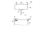
図1、2に示すように、排水ポンプ1は、合成樹脂製のポンプ本体10を備えており、ポンプ本体10は、下方に突出する吸込口12と、水平方向に突出する吐出口16と、吸込口12及び吐出口16に連通するポンプ室14とを有する。
As shown in FIGS. 1 and 2, the drainage pump 1 includes a
ポンプ室14内には回転羽根20が配設される。回転羽根20は、取付軸21から径方向に延びる複数の大径羽根(図示せず)と、各大径羽根から下方に向けて軸方向に延びる複数の小径羽根22と、複数の大径羽根の下縁部を連結するとともに中心に開口部を有する円盤23と、複数の大径羽根の外周部を連結するリング24とを備える。取付軸21の中心に形成した取付穴に後述するモールドモータ100の出力軸110が圧入される。モールドモータ100を駆動すると、回転羽根20がポンプ室14内で回転する。
A
ポンプ本体10の上面は開口していて、これを覆うようにモータ受け部材50が取り付けられる。モータ受け部材50は、ポンプ本体10に一体成形された一対のフック状の取付部80によりポンプ本体10に結合される。モータ受け部材50は、ポンプ本体10の開口部を覆う蓋部52を有し、この蓋部52とポンプ本体10との間にはOリング40が配設される。
The upper surface of the pump
蓋部52は回転羽根20の取付軸21が貫通する開口部54を有し、排水ポンプ1の停止時には、ポンプ室14内の水が開口部54から外部へ噴出するが、取付軸21と出力軸110との間に取り付けられた水切り30により、この水がモールドモータ100側へ飛散するのを防止する。
The
モータ受け部材50の内側には複数の支柱56が形成され、モールドモータ100の下面を支持する。モータ受け部材50の上部には上面が開口するモータ受け部60が形成されている。モータ受け部60は下端部に段付部66を有し、この段付部66でモールドモータ100を支持する。
A plurality of
モータ受け部60の上端には上外方へ突出する複数の取付脚70が一体成形される。この取付脚70には、排水ポンプ1を室内ユニットへ固定するためのねじが貫通する取付孔72が形成されている。本実施例にあっては、3個の取付脚70が設けられており、これらの取付脚70の取付孔72の中心は、モータ受け部60と同心の1つの円周上に位置するとともに、モータ受け部60の中心点の周りに等角度間隔をおいて配置されている。
A plurality of mounting
そして、モータ受け部60の上端部における各取付脚70に対応する位置に取付穴90(第2嵌合部)が形成されている。図3、4に示すように、本実施例にあっては、この取付穴90は四角穴に形成されている。この取付穴90とモールドモータ100の凸部130(第1嵌合部)とにより、モールドモータ100をモータ受け部60にスナップフィット結合で着脱可能に固定する固定手段を構成する。
And the attachment hole 90 (2nd fitting part) is formed in the position corresponding to each
モールドモータ100は、固定子をBMC等の防水性樹脂で覆ったモータ本体105に上軸受部120及び下軸受部122を介して出力軸110を回転自在に装備したものである。このような構造であると、別体の防水カバーをモータに取り付ける必要がなくなるので、部品点数が低減する。そして、これに伴って、従来は防水カバーに設けていた取付脚70をモータ受け部材50に設けている。
The molded
そして、モールドモータ100の上部の外周部に3個の凸部130が一体成形されている。図4に示すように、凸部130の下面は傾斜面132とされており、モールドモータ100の各凸部130をモータ受け部60の取付穴90の位置に合わせてモールドモータ100をモータ受け部60内に挿入すると、モールドモータ100の底面がモータ受け部60の段付部66に当接するのとほぼ同時に各凸部130が取付穴90に嵌合してモールドモータ100がモータ受け部60に固定される。
The three
凸部130の外径寸法は、取付穴90の内径寸法よりわずかに小さく形成されている。モータ受け部60は樹脂材料で形成されており、径方向に弾性変形する。モールドモータ100をモータ受け部60内に押し込むことにより、凸部130は取付穴90に対していわゆるスナップフィット結合で結合される。
The outer diameter of the
上述したように、モータ受け部材50の取付脚70の取付孔72の中心は、モータ受け部60と同心の1つの円周上に位置するとともに、モータ受け部60の中心点の周りに等角度間隔をおいて配置されているため、各取付脚70を室内ユニットへねじ止めするとき、各取付脚70を介してモータ受け部60に作用する応力が相殺されるので、各スナップフィット結合部からモールドモータ100に作用する応力がほぼ均一となる。これにより、モールドモータ100に接続された回転羽根20とポンプ本体10との同心性が向上し、回転羽根20とポンプ本体10との間に形成される隙間がほぼ均一になるので、騒音・振動が低減する。
As described above, the center of the
本発明では、回転羽根20を回転させるモータがモールドモータ100であるので、モータを覆う防水カバーが無くても防水性を確保することができる。また、室内ユニットへの取付脚70をモータ受け部材50に一体成形している。したがって、従来に比べて部品点数が少なく、製造コストが低減する。
In the present invention, since the motor that rotates the
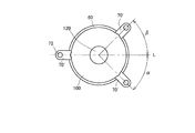
図5は本発明の他の実施例を示す。なお、図1の実施例と同一の部分には同一の符号を付して説明は省略する。本実施例にあってもモータ受け部60はその上端に3個の取付脚70’を備える。そして、1つの取付脚70’の取付孔72の中心とモータ受け部60の中心とを通る直線Lに対して残りの2つの取付脚70’の中心が線対称に配置されている。すなわち、角度αとβが等しくなっている。
FIG. 5 shows another embodiment of the present invention. In addition, the same code | symbol is attached | subjected to the part same as the Example of FIG. 1, and description is abbreviate | omitted. Even in this embodiment, the
本実施例においても、各取付脚70’を室内ユニットへねじ止めするとき、各取付脚70’を介してモータ受け部60に作用する応力が相殺されるため、各スナップフィット結合部からモールドモータ100に作用する応力がほぼ均一になり、回転羽根20とポンプ本体10との同心性が向上するので、騒音・振動を低減することができる。
Also in the present embodiment, when each mounting leg 70 'is screwed to the indoor unit, the stress acting on the
1 排水ポンプ
10 ポンプ本体
12 吸込口
14 ポンプ室
16 吐出口
20 回転羽根
50 モータ受け部材
52 蓋部
60 モータ受け部
70 取付脚
90 取付穴(第2嵌合部)
100 モールドモータ
130 凸部(第1嵌合部)
DESCRIPTION OF SYMBOLS 1 Drain pump 10 Pump
100
Claims (3)
吸込口、吐出口及びそれらに連通するポンプ室を有するポンプ本体と、前記ポンプ室内に配設される回転羽根と、前記回転羽根を回転させるモータと、前記ポンプ本体の上部に組み付けられるとともに前記モータを支持するモータ受け部材とを備え、
前記モータがモールドモータであり、
前記モータ受け部材は、前記ポンプ本体の開口部を覆う蓋部と、前記蓋部と一体成形されるモータ受け部と、前記モータ受け部に一体成形され、前記室内ユニットに取り付けるための複数の取付脚と、前記複数の取付脚に対応する位置に形成された複数の取付穴と、を有し、
前記モールドモータには、前記複数の取付穴に対応する位置に複数の凸部が一体成形されており、
前記複数の取付穴と前記複数の凸部とが結合することにより、前記モールドモータをスナップフィット結合で固定する固定手段を形成することを特徴とする排水ポンプ。 A drainage pump that is installed in an indoor unit of an air conditioner and sucks up drain water generated during operation of the air conditioner and discharges it to the outside.
A pump body having a suction port, a discharge port, and a pump chamber communicating with the suction port, a rotating blade disposed in the pump chamber, a motor for rotating the rotating blade, and an upper portion of the pump body, and the motor A motor receiving member that supports
The motor is a molded motor;
The motor receiving member includes a lid portion that covers the opening of the pump body, a motor receiving portion that is integrally formed with the lid portion, and a plurality of attachments that are integrally formed with the motor receiving portion and are attached to the indoor unit. A leg, and a plurality of mounting holes formed at positions corresponding to the plurality of mounting legs ,
In the molded motor, a plurality of convex portions are integrally formed at positions corresponding to the plurality of mounting holes,
A drainage pump characterized in that a fixing means for fixing the mold motor by snap-fit coupling is formed by coupling the plurality of mounting holes and the plurality of convex portions .
The three mounting holes are provided, and the centers of the other two mounting holes are arranged symmetrically with respect to a straight line passing through the center of one second fitting portion and the center of the motor receiving portion. The drainage pump according to claim 1, wherein
Priority Applications (1)
| Application Number | Priority Date | Filing Date | Title |
|---|---|---|---|
| JP2012032494A JP5934515B2 (en) | 2012-02-17 | 2012-02-17 | Drainage pump |
Applications Claiming Priority (1)
| Application Number | Priority Date | Filing Date | Title |
|---|---|---|---|
| JP2012032494A JP5934515B2 (en) | 2012-02-17 | 2012-02-17 | Drainage pump |
Publications (3)
| Publication Number | Publication Date |
|---|---|
| JP2013167234A JP2013167234A (en) | 2013-08-29 |
| JP2013167234A5 JP2013167234A5 (en) | 2015-02-19 |
| JP5934515B2 true JP5934515B2 (en) | 2016-06-15 |
Family
ID=49177804
Family Applications (1)
| Application Number | Title | Priority Date | Filing Date |
|---|---|---|---|
| JP2012032494A Active JP5934515B2 (en) | 2012-02-17 | 2012-02-17 | Drainage pump |
Country Status (1)
| Country | Link |
|---|---|
| JP (1) | JP5934515B2 (en) |
Cited By (1)
| Publication number | Priority date | Publication date | Assignee | Title |
|---|---|---|---|---|
| JP2019031917A (en) * | 2017-08-04 | 2019-02-28 | 株式会社鷺宮製作所 | Drainage pump |
Families Citing this family (2)
| Publication number | Priority date | Publication date | Assignee | Title |
|---|---|---|---|---|
| CN106640678B (en) * | 2016-10-31 | 2023-11-28 | 佛山市顺德区美的电子科技有限公司 | Mobile air conditioner, water pumping device and water pumping method thereof |
| JP2018091231A (en) * | 2016-12-02 | 2018-06-14 | 株式会社鷺宮製作所 | Drainage pup and air-conditioner |
Family Cites Families (4)
| Publication number | Priority date | Publication date | Assignee | Title |
|---|---|---|---|---|
| DE7623892U1 (en) * | 1976-07-29 | 1977-01-27 | Tunze, Norbert, 8122 Penzberg | CENTRIFUGAL PUMP |
| JPH0115914Y2 (en) * | 1981-01-13 | 1989-05-11 | ||
| JP4374382B2 (en) * | 2007-05-25 | 2009-12-02 | 株式会社鷺宮製作所 | Motor waterproof structure, drainage pump and air conditioner |
| JP2010275972A (en) * | 2009-05-29 | 2010-12-09 | Fuji Koki Corp | Drainage pump |
-
2012
- 2012-02-17 JP JP2012032494A patent/JP5934515B2/en active Active
Cited By (1)
| Publication number | Priority date | Publication date | Assignee | Title |
|---|---|---|---|---|
| JP2019031917A (en) * | 2017-08-04 | 2019-02-28 | 株式会社鷺宮製作所 | Drainage pump |
Also Published As
| Publication number | Publication date |
|---|---|
| JP2013167234A (en) | 2013-08-29 |
Similar Documents
| Publication | Publication Date | Title |
|---|---|---|
| JP5012736B2 (en) | Centrifugal blower | |
| JP5636788B2 (en) | Blower fan | |
| KR102599971B1 (en) | Motor for drone and drone having the same | |
| US20150252812A1 (en) | Housing for a ventilator or fan | |
| US9568015B2 (en) | Centrifugal fan | |
| US20100068081A1 (en) | Axial fan | |
| JP2010031822A (en) | Miniature fan | |
| JP5934515B2 (en) | Drainage pump | |
| JP6091066B2 (en) | Drain pump | |
| KR20130110440A (en) | Impeller and vacuum cleaner motor assembly having the same | |
| US10211697B2 (en) | Cover device for an electronics housing of an electric motor | |
| US7175392B2 (en) | Ceiling fan motor with stationary shaft | |
| KR101284391B1 (en) | Drain pump | |
| JP2017150327A (en) | Blower | |
| JP5953081B2 (en) | Drainage pump | |
| JP2013167234A5 (en) | ||
| JP2016113941A (en) | Drainage pump | |
| JP2010014047A (en) | Impeller for centrifugal pump | |
| JP6063668B2 (en) | pump | |
| CN208534779U (en) | A kind of diversion seat and water pump, dish-washing machine | |
| JP2018157716A (en) | Electric motor and bearing bracket | |
| WO2021241340A1 (en) | Drain pump | |
| JP6554790B2 (en) | Fan device | |
| WO2018166144A1 (en) | Waterproof structure of external rotor electric motor | |
| KR20120053779A (en) | Fluid motor pump |
Legal Events
| Date | Code | Title | Description |
|---|---|---|---|
| A521 | Request for written amendment filed |
Free format text: JAPANESE INTERMEDIATE CODE: A523 Effective date: 20141218 |
|
| A621 | Written request for application examination |
Free format text: JAPANESE INTERMEDIATE CODE: A621 Effective date: 20141218 |
|
| A977 | Report on retrieval |
Free format text: JAPANESE INTERMEDIATE CODE: A971007 Effective date: 20150910 |
|
| A131 | Notification of reasons for refusal |
Free format text: JAPANESE INTERMEDIATE CODE: A131 Effective date: 20150929 |
|
| A521 | Request for written amendment filed |
Free format text: JAPANESE INTERMEDIATE CODE: A523 Effective date: 20151102 |
|
| TRDD | Decision of grant or rejection written | ||
| A01 | Written decision to grant a patent or to grant a registration (utility model) |
Free format text: JAPANESE INTERMEDIATE CODE: A01 Effective date: 20160412 |
|
| A61 | First payment of annual fees (during grant procedure) |
Free format text: JAPANESE INTERMEDIATE CODE: A61 Effective date: 20160509 |
|
| R150 | Certificate of patent or registration of utility model |
Ref document number: 5934515 Country of ref document: JP Free format text: JAPANESE INTERMEDIATE CODE: R150 |
|
| R250 | Receipt of annual fees |
Free format text: JAPANESE INTERMEDIATE CODE: R250 |
|
| R250 | Receipt of annual fees |
Free format text: JAPANESE INTERMEDIATE CODE: R250 |
|
| R250 | Receipt of annual fees |
Free format text: JAPANESE INTERMEDIATE CODE: R250 |