JP5934334B2 - Motion detection circuit and method - Google Patents
Motion detection circuit and method Download PDFInfo
- Publication number
- JP5934334B2 JP5934334B2 JP2014502567A JP2014502567A JP5934334B2 JP 5934334 B2 JP5934334 B2 JP 5934334B2 JP 2014502567 A JP2014502567 A JP 2014502567A JP 2014502567 A JP2014502567 A JP 2014502567A JP 5934334 B2 JP5934334 B2 JP 5934334B2
- Authority
- JP
- Japan
- Prior art keywords
- magnetic field
- signal
- output signal
- threshold detector
- tracking
- Prior art date
- Legal status (The legal status is an assumption and is not a legal conclusion. Google has not performed a legal analysis and makes no representation as to the accuracy of the status listed.)
- Active
Links
Images


Classifications
-
- G—PHYSICS
- G01—MEASURING; TESTING
- G01D—MEASURING NOT SPECIALLY ADAPTED FOR A SPECIFIC VARIABLE; ARRANGEMENTS FOR MEASURING TWO OR MORE VARIABLES NOT COVERED IN A SINGLE OTHER SUBCLASS; TARIFF METERING APPARATUS; MEASURING OR TESTING NOT OTHERWISE PROVIDED FOR
- G01D5/00—Mechanical means for transferring the output of a sensing member; Means for converting the output of a sensing member to another variable where the form or nature of the sensing member does not constrain the means for converting; Transducers not specially adapted for a specific variable
- G01D5/12—Mechanical means for transferring the output of a sensing member; Means for converting the output of a sensing member to another variable where the form or nature of the sensing member does not constrain the means for converting; Transducers not specially adapted for a specific variable using electric or magnetic means
- G01D5/244—Mechanical means for transferring the output of a sensing member; Means for converting the output of a sensing member to another variable where the form or nature of the sensing member does not constrain the means for converting; Transducers not specially adapted for a specific variable using electric or magnetic means influencing characteristics of pulses or pulse trains; generating pulses or pulse trains
- G01D5/24471—Error correction
- G01D5/2448—Correction of gain, threshold, offset or phase control
-
- G—PHYSICS
- G01—MEASURING; TESTING
- G01D—MEASURING NOT SPECIALLY ADAPTED FOR A SPECIFIC VARIABLE; ARRANGEMENTS FOR MEASURING TWO OR MORE VARIABLES NOT COVERED IN A SINGLE OTHER SUBCLASS; TARIFF METERING APPARATUS; MEASURING OR TESTING NOT OTHERWISE PROVIDED FOR
- G01D5/00—Mechanical means for transferring the output of a sensing member; Means for converting the output of a sensing member to another variable where the form or nature of the sensing member does not constrain the means for converting; Transducers not specially adapted for a specific variable
- G01D5/12—Mechanical means for transferring the output of a sensing member; Means for converting the output of a sensing member to another variable where the form or nature of the sensing member does not constrain the means for converting; Transducers not specially adapted for a specific variable using electric or magnetic means
- G01D5/244—Mechanical means for transferring the output of a sensing member; Means for converting the output of a sensing member to another variable where the form or nature of the sensing member does not constrain the means for converting; Transducers not specially adapted for a specific variable using electric or magnetic means influencing characteristics of pulses or pulse trains; generating pulses or pulse trains
-
- G—PHYSICS
- G01—MEASURING; TESTING
- G01D—MEASURING NOT SPECIALLY ADAPTED FOR A SPECIFIC VARIABLE; ARRANGEMENTS FOR MEASURING TWO OR MORE VARIABLES NOT COVERED IN A SINGLE OTHER SUBCLASS; TARIFF METERING APPARATUS; MEASURING OR TESTING NOT OTHERWISE PROVIDED FOR
- G01D5/00—Mechanical means for transferring the output of a sensing member; Means for converting the output of a sensing member to another variable where the form or nature of the sensing member does not constrain the means for converting; Transducers not specially adapted for a specific variable
- G01D5/12—Mechanical means for transferring the output of a sensing member; Means for converting the output of a sensing member to another variable where the form or nature of the sensing member does not constrain the means for converting; Transducers not specially adapted for a specific variable using electric or magnetic means
- G01D5/14—Mechanical means for transferring the output of a sensing member; Means for converting the output of a sensing member to another variable where the form or nature of the sensing member does not constrain the means for converting; Transducers not specially adapted for a specific variable using electric or magnetic means influencing the magnitude of a current or voltage
- G01D5/142—Mechanical means for transferring the output of a sensing member; Means for converting the output of a sensing member to another variable where the form or nature of the sensing member does not constrain the means for converting; Transducers not specially adapted for a specific variable using electric or magnetic means influencing the magnitude of a current or voltage using Hall-effect devices
- G01D5/145—Mechanical means for transferring the output of a sensing member; Means for converting the output of a sensing member to another variable where the form or nature of the sensing member does not constrain the means for converting; Transducers not specially adapted for a specific variable using electric or magnetic means influencing the magnitude of a current or voltage using Hall-effect devices influenced by the relative movement between the Hall device and magnetic fields
-
- G—PHYSICS
- G01—MEASURING; TESTING
- G01D—MEASURING NOT SPECIALLY ADAPTED FOR A SPECIFIC VARIABLE; ARRANGEMENTS FOR MEASURING TWO OR MORE VARIABLES NOT COVERED IN A SINGLE OTHER SUBCLASS; TARIFF METERING APPARATUS; MEASURING OR TESTING NOT OTHERWISE PROVIDED FOR
- G01D5/00—Mechanical means for transferring the output of a sensing member; Means for converting the output of a sensing member to another variable where the form or nature of the sensing member does not constrain the means for converting; Transducers not specially adapted for a specific variable
- G01D5/12—Mechanical means for transferring the output of a sensing member; Means for converting the output of a sensing member to another variable where the form or nature of the sensing member does not constrain the means for converting; Transducers not specially adapted for a specific variable using electric or magnetic means
- G01D5/244—Mechanical means for transferring the output of a sensing member; Means for converting the output of a sensing member to another variable where the form or nature of the sensing member does not constrain the means for converting; Transducers not specially adapted for a specific variable using electric or magnetic means influencing characteristics of pulses or pulse trains; generating pulses or pulse trains
- G01D5/24471—Error correction
- G01D5/2449—Error correction using hard-stored calibration data
Description
[0001] 本発明は、一般的には、集積回路に関し、更に特定すれば、強磁性物体の移動(movement)を検出する集積回路に関する。 [0001] The present invention relates generally to integrated circuits, and more particularly to integrated circuits that detect movement of a ferromagnetic object.
[0002] 強磁性物品および/または磁性物品を検出する磁場センサ(例えば、回転検出器)は、周知である。強磁性物品または磁性物品に伴う磁場は、ホール・エレメントまたは磁気抵抗エレメントというような、磁場検知エレメントによって検出され、このエレメントは、検出した磁場に比例する信号(即ち、磁場信号)を供給する。構成の中には、磁場信号が電気信号である場合もある。 [0002] Magnetic field sensors (for example, rotation detectors) for detecting ferromagnetic articles and / or magnetic articles are well known. The magnetic field associated with a ferromagnetic or magnetic article is detected by a magnetic field sensing element, such as a Hall element or a magnetoresistive element, which provides a signal proportional to the detected magnetic field (ie, a magnetic field signal). In some configurations, the magnetic field signal is an electrical signal.
[0003] 磁場センサは、磁場信号を処理して出力信号を生成する。この出力信号は、磁場信号が、ピーク(正および/または負のピーク)に近い閾値、または他の何らかのレベル、例えば、磁場信号のゼロ交差に近い閾値を交差する毎に状態を変化させる。したがって、この出力信号は、強磁性物体または磁性物体、例えば、ギアまたはリング・マグネットの移動速度(例えば、回転速度)を示すエッジ・レートまたは周期を有する。 [0003] A magnetic field sensor processes a magnetic field signal to generate an output signal. This output signal changes state each time the magnetic field signal crosses a threshold close to a peak (positive and / or negative peak) or some other level, eg, a threshold close to the zero crossing of the magnetic field signal. Thus, this output signal has an edge rate or period that indicates the moving speed (eg, rotational speed) of a ferromagnetic or magnetic object, eg, a gear or ring magnet.
[0004] 磁場センサの用途の1つは、硬質の磁性ギアまたは軟質の磁性ギアのいずれであれ、回転強磁性ギアの各歯の接近および後退(retreat)を検出することである。特定的な構成の中には、極性が交互する磁気領域(永久または硬質磁性体を含む)を有するリング・マグネットが、強磁性ギアに結合されている場合や、それ自体によって用いられる場合がある。磁場センサは、リング・マグネットの磁気領域の接近および後退に応答する。他の構成では、ギアが固定磁石に近接して配置され、このギアが回転するに連れて、磁場センサが磁場の外乱に応答する。 [0004] One application of magnetic field sensors is to detect the approach and retreat of each tooth of a rotating ferromagnetic gear, whether it is a hard magnetic gear or a soft magnetic gear. In certain configurations, a ring magnet with magnetic regions of alternating polarity (including permanent or hard magnetic material) may be coupled to the ferromagnetic gear or used by itself . The magnetic field sensor responds to the approach and retraction of the magnetic region of the ring magnet. In other configurations, a gear is placed in close proximity to the fixed magnet and the magnetic field sensor responds to magnetic field disturbances as the gear rotates.
[0005] ピーク−ピーク比率検出器(peak-to-peak percentage detector)(または閾値検出器)と呼ばれる磁場センサの一種では、1つ以上の閾値レベルが、ピーク−ピーク磁場信号のそれぞれの比率に等しくなっている。1つのこのようなピーク−ピーク比率検出器が、"Detection of Passing Magnetic Articles While Periodically Adapting Detection Threshold"(周期的に検出閾値を適応させながらの磁性体物品通過の検出)と題し本発明の譲受人に譲渡されている米国特許第5,917,320号に記載されている。 [0005] In one type of magnetic field sensor called a peak-to-peak percentage detector (or threshold detector), one or more threshold levels are at each ratio of the peak-to-peak magnetic field signal. Are equal. One such peak-to-peak ratio detector is entitled "Detection of Passing Magnetic Articles While Periodically Adapting Detection Threshold" and is assigned to the present invention. U.S. Pat. No. 5,917,320, assigned to U.S. Pat.
[0006] 勾配作動検出器(slope activated detector)(または、ピーク基準検出器(peak referenced detector))と称されることもある他の一種の磁場センサが、"Detection Of Passing Magnetic Articles With a Peak Referenced Threshold Detector"(ピーク基準閾値検出器による磁性物品通過の検出)と題し、同様に本発明の譲受人に譲渡されている米国特許第6,091,239号に記載されている。ピーク基準磁場センサでは、閾値信号は、磁場信号の正および負ピーク(即ち、ピークおよびバレー)とは所定量だけ異なる。つまり、この種の磁場センサでは、磁場信号のピークまたはバリーよりも所定量だけ磁場信号が外れると、出力信号は状態を変化させる。 [0006] Another type of magnetic field sensor, sometimes referred to as a slope activated detector (or peak referenced detector), is "Detection Of Passing Magnetic Articles With a Peak Referenced". US Pat. No. 6,091,239, entitled “Threshold Detector” (detection of passage of magnetic articles by a peak reference threshold detector), also assigned to the assignee of the present invention. In a peak reference magnetic field sensor, the threshold signal differs from the positive and negative peaks (ie, peaks and valleys) of the magnetic field signal by a predetermined amount. That is, in this type of magnetic field sensor, the output signal changes state when the magnetic field signal deviates by a predetermined amount from the peak or valley of the magnetic field signal.
[0007] 尚、以上で説明した閾値検出器および以上で説明したピーク基準検出器は双方とも、磁場信号の正および負のピークを識別することができる回路を有するので、閾値検出器およびピーク基準検出器の双方は、磁場信号の正ピークおよび/または負ピークを検出するように構成された回路部分を含むことは言うまでもない。しかしながら、閾値検出器およびピーク基準検出器は、各々異なる方法で検出したピークを用いる。 [0007] It should be noted that both the threshold detector described above and the peak reference detector described above have circuits that can identify positive and negative peaks of the magnetic field signal, so that the threshold detector and the peak reference It will be appreciated that both detectors include circuit portions configured to detect positive and / or negative peaks of the magnetic field signal. However, the threshold detector and the peak reference detector each use peaks detected in different ways.
[0008] 磁場信号の正および負のピークを精度高く検出するために、回転検出器は磁場信号の少なくとも一部を追跡することができる。この目的のために、通例、1つ以上のディジタル/アナログ変換器(DAC)を用いて、磁場信号を追跡する追跡信号を生成することができる。例えば、先に引用した米国特許第5,917,320号および第6,091,239号では、2つのDACが用いられており、一方(PDAC)は磁場信号の正のピークを検出するためにあり、他方(NDAC)は磁場信号の負ピークを検出するためにある。 [0008] In order to accurately detect the positive and negative peaks of the magnetic field signal, the rotation detector can track at least a portion of the magnetic field signal. For this purpose, one or more digital / analog converters (DACs) can typically be used to generate a tracking signal that tracks the magnetic field signal. For example, in the above cited US Pat. Nos. 5,917,320 and 6,091,239, two DACs are used, one (PDAC) to detect the positive peak of the magnetic field signal. Yes, the other (NDAC) is for detecting the negative peak of the magnetic field signal.
[0009] ある種の回転検出器は、1種類以上の初期化または較正を、例えば、回転検出器の起動または電力投入に近い時点で、またはそれ以外で、所望に応じて時々実行する場合がある。較正の一種では、先に述べた閾値レベルがその間に決定される。ある種の較正では、磁場信号の所定数のサイクルにしたがって、較正が行われる時間間隔を決定する。つまり、速い磁場信号(例えば、高速回転ギアの磁場信号)では、較正に利用可能な時間は短い。移動または回転が速く、較正に利用可能な時間が短い用途では、回転検出器は精度高い動き検出を十分に速く行うことができない場合がある。 [0009] Certain rotation detectors may perform one or more initializations or calibrations from time to time, as desired, for example, near the start-up or power-up of the rotation detector, or otherwise. is there. In one type of calibration, the previously mentioned threshold level is determined in the meantime. In some types of calibration, the time interval during which calibration is performed is determined according to a predetermined number of cycles of the magnetic field signal. That is, with a fast magnetic field signal (for example, a magnetic field signal of a high-speed rotating gear), the time available for calibration is short. In applications where movement or rotation is fast and the time available for calibration is short, the rotation detector may not be able to perform accurate motion detection fast enough.
[0010] したがって、比較的長い時間枠と同様に、比較的短い時間枠内でも精度が高く信頼性の高い動き検出(回転速度および/または回転方向)を行うことができる移動検出器(例えば、回転検出器)を提供することができれば望ましいということになる。 [0010] Therefore, as with a relatively long time frame, a movement detector (for example, a rotational speed and / or direction) that can perform motion detection (rotational speed and / or rotational direction) with high accuracy and reliability within a relatively short time frame. It would be desirable if a rotation detector could be provided.
[0011] 概略的な全体像では、本発明は、比較的短い時間期間内において物体の移動を検出することができる回路の態様を対象とし、実施形態の中には、比較的短い時間期間内に物体の移動速度および/または移動方向を検出することができる回路を対象とするものもある。この回路は、物体の磁場と関連のある磁場信号の所定の閾値に基づいて、1つ以上の所定の閾値検出器を用いて、物体の移動を検出する。また、この回路は、1つ以上の追跡閾値検出器を用いて、時の経過と共に磁場信号を追跡することによって、物体の移動を検出する。所定の閾値検出器は、磁場信号の正および負のピークを追跡するためには較正期間(例えば、回路の起動または電源投入からある期間を含むことがある期間)を必要とする追跡閾値検出器と比較して、素早く物体の移動を検出することができる。この回路は、所定の条件に基づいて、所定の閾値検出器または追跡閾値検出器の内1つの出力に関係する出力を生成するために、出力選択器を含む。実施形態の中には、所定の条件が、磁場信号のサイクル数、または追跡閾値検出器の較正時間期間に関係する場合もある。 [0011] In a general overview, the present invention is directed to an aspect of a circuit that can detect movement of an object within a relatively short time period, and in some embodiments, within a relatively short time period. There are also circuits that can detect the moving speed and / or moving direction of an object. The circuit detects the movement of the object using one or more predetermined threshold detectors based on a predetermined threshold of the magnetic field signal associated with the object's magnetic field. The circuit also detects the movement of the object by tracking the magnetic field signal over time using one or more tracking threshold detectors. The predetermined threshold detector requires a calibration period (eg, a period that may include a period from circuit activation or power-up) to track the positive and negative peaks of the magnetic field signal. Compared with, the movement of the object can be detected quickly. The circuit includes an output selector to generate an output related to the output of one of the predetermined threshold detector or tracking threshold detector based on a predetermined condition. In some embodiments, the predetermined condition may relate to the number of cycles of the magnetic field signal, or the tracking threshold detector calibration time period.
[0012] ある実施形態では、移動物体の速度および方向を検出可能な回路が、第1対の磁場エレメント(第1磁場信号を供給するように動作する)と第2対の磁場エレメント(第2磁場信号を供給するように動作する)とを含む。第1および第2磁場信号は、第1および第2対の磁場エレメントの応答に比例する。また、この回路は、第1および第2磁場信号に応答する1対の追跡閾値検出器も含む。出力選択器は、1対の所定閾値検出器および1対の追跡閾値検出器によって生成された組み合わせに関係する出力を、所定の条件に基づいて生成する。 [0012] In an embodiment, a circuit capable of detecting the velocity and direction of a moving object includes a first pair of magnetic field elements (operating to provide a first magnetic field signal) and a second pair of magnetic field elements (second Operating to provide a magnetic field signal). The first and second magnetic field signals are proportional to the response of the first and second pairs of magnetic field elements. The circuit also includes a pair of tracking threshold detectors responsive to the first and second magnetic field signals. The output selector generates an output related to the combination generated by the pair of predetermined threshold detectors and the pair of tracking threshold detectors based on the predetermined condition.
[0013] この回路は、物体の移動を素早く検出し、このような物体の移動を示す出力信号を生成することが望まれる、必要とされる、または必要である用途において用いるとよい。物体は、いずれの特定の種類の物体にも限定されず、歯が付いたギア、クランクシャフト、カムシャフト、おもちゃまたは工具の機械的構成部品等を含むことができるが、これらに限定されるのではない。物体は、軟質強磁性物体のような、強磁性物体を含むことができる。非限定的な例として、本回路は、車両におけるギアの移動(例えば、車両運転中における変速ギアの回転方向)、車両の車輪の移動(例えば、車両の前方または後方移動を示す出力信号を精製するため)を検出するために用いることができる。 [0013] The circuit may be used in applications where it is desired, required, or necessary to quickly detect object movement and generate an output signal indicative of such object movement. Objects are not limited to any particular type of object, but may include, but are not limited to, toothed gears, crankshafts, camshafts, toy or tool mechanical components, etc. is not. The object can include a ferromagnetic object, such as a soft ferromagnetic object. As a non-limiting example, the circuit refines output signals indicating gear movement in the vehicle (eg, the direction of rotation of the transmission gear during vehicle operation), vehicle wheel movement (eg, forward or backward movement of the vehicle). Can be used to detect).
[0014] 本発明の一態様によれば、物体の移動に応答する回路は、この物体に伴う磁場に比例する磁場信号を供給するように動作する磁場検知エレメントと、磁場信号に応答する第1入力と、所定の閾値に応答する第2入力と、所定閾値検出器出力信号を供給する出力とを有する比較器を含む、所定閾値検出器と、磁場信号を受け取るように結合され、磁場信号の正および負のピークを追跡し、追跡信号を生成するように構成されている追跡回路と、磁場信号に応答する第1入力、追跡信号に関係する入力信号に応答する第2入力、追跡閾値検出器出力信号を供給する出力を有する比較器を含む追跡閾値検出器とを含む。また、この回路は、追跡閾値検出器出力信号に応答する第1入力と、所定閾値検出器出力信号に応答する第2入力とを有し、所定閾値検出器出力信号または追跡閾値検出器出力信号の内少なくとも1つに関係する回路出力信号を、所定の条件に基づいて生成するように構成されている出力信号選択器も含む。 [0014] According to one aspect of the invention, a circuit responsive to movement of an object includes a magnetic field sensing element that operates to provide a magnetic field signal proportional to the magnetic field associated with the object, and a first responsive to the magnetic field signal. A predetermined threshold detector including a comparator having an input, a second input responsive to the predetermined threshold, and an output for providing a predetermined threshold detector output signal; A tracking circuit configured to track positive and negative peaks and generate a tracking signal, a first input responsive to a magnetic field signal, a second input responsive to an input signal related to the tracking signal, tracking threshold detection A tracking threshold detector including a comparator having an output for providing a comparator output signal. The circuit also has a first input responsive to the tracking threshold detector output signal and a second input responsive to the predetermined threshold detector output signal, the predetermined threshold detector output signal or the tracking threshold detector output signal. And an output signal selector configured to generate a circuit output signal related to at least one of the output signals based on a predetermined condition.
[0015] 他の実施形態では、この回路は以下の特徴の内1つ以上を含む。所定の条件は、磁場信号の所定のサイクル数に関係する。所定の条件は、所定閾値検出器出力信号の所定のサイクル数に関係する。所定の条件は、所定の時間に対応する。磁場検知エレメントに結合され磁場信号を処理するように構成されている自動利得制御であって、所定の条件が自動利得制御の条件に対応する、自動利得制御と、磁場検知エレメントに結合され磁場信号を処理するように構成されている自動オフセット調節であって、所定の条件が自動オフセット調節の条件に対応する、自動オフセット調節との内少なくとも1つを含む。出力信号選択器は、更に、追跡閾値検出器の較正時間期間中に所定閾値検出器出力信号に関係する回路出力信号を生成し、較正時間期間の後に追跡閾値検出器出力信号に関係する回路出力信号を生成するように構成されており、所定の条件は較正時間期間の終了に対応する。 [0015] In other embodiments, the circuit includes one or more of the following features. The predetermined condition relates to a predetermined number of cycles of the magnetic field signal. The predetermined condition relates to a predetermined number of cycles of the predetermined threshold detector output signal. The predetermined condition corresponds to a predetermined time. Automatic gain control coupled to a magnetic field sensing element and configured to process a magnetic field signal, wherein the predetermined condition corresponds to the automatic gain control condition and the magnetic field signal coupled to the magnetic field sensing element Automatic offset adjustment, wherein the predetermined condition includes at least one of the automatic offset adjustment corresponding to the automatic offset adjustment condition. The output signal selector further generates a circuit output signal related to the predetermined threshold detector output signal during the calibration threshold period of the tracking threshold detector, and a circuit output related to the tracking threshold detector output signal after the calibration time period. The signal is configured to be generated, and the predetermined condition corresponds to the end of the calibration time period.
[0016] 他の実施形態では、本回路は、以下の特徴の内1つ以上を含む。磁場検知エレメントは、第1対の磁場検知エレメントであり、磁場信号は第1磁場信号であり、所定閾値検出器は、第1磁場信号に応答し第1所定閾値検出器位相を有する第1所定閾値検出器出力信号を供給するように動作する第1所定閾値検出器である。本回路は、更に、第1磁場信号を供給するように動作する第2対の磁場検知エレメントと、第2所定閾値検出器と含み、第2所定閾値検出器が、第2磁場信号に応答する第1入力、所定の閾値に応答する第2入力、および第2所定閾値検出器位相を有する第2所定閾値検出器出力信号を供給する出力を有する比較器を備えている。信号選択器は、更に、第2所定閾値検出器出力信号に応答する第3入力を備えており、第1および第2所定閾値検出器位相の差が、物体の移動方向を示す。所定の条件は、第1または第2磁場信号の内1つの所定のサイクル数に関係する。所定の条件は、第1または第2所定閾値検出器出力信号の内1つの所定のサイクル数に関係する。所定の条件は、所定時間に対応する。第1対または第2対の磁場検知エレメントに結合され、第1または第2磁場信号の内対応する1つを処理するように構成されている自動利得制御であって、所定の条件が自動利得制御の条件に対応する、自動利得制御と、第1または第2対の磁場検知エレメントの内1つに結合され、第1または第2磁場信号の内対応する1つを処理するように構成されている自動オフセット調節であって、所定の条件が自動利得制御の条件に対応する、自動オフセット調節との内少なくとも1つを含む。 [0016] In other embodiments, the circuit includes one or more of the following features. The magnetic field sensing element is a first pair of magnetic field sensing elements, the magnetic field signal is a first magnetic field signal, and the predetermined threshold detector is a first predetermined threshold detector phase in response to the first magnetic field signal. A first predetermined threshold detector that operates to provide a threshold detector output signal. The circuit further includes a second pair of magnetic field sensing elements operable to provide a first magnetic field signal and a second predetermined threshold detector, wherein the second predetermined threshold detector is responsive to the second magnetic field signal. A comparator has a first input, a second input responsive to a predetermined threshold, and an output for providing a second predetermined threshold detector output signal having a second predetermined threshold detector phase. The signal selector further comprises a third input responsive to the second predetermined threshold detector output signal, the difference between the first and second predetermined threshold detector phases indicating the direction of movement of the object. The predetermined condition relates to a predetermined cycle number of one of the first and second magnetic field signals. The predetermined condition relates to a predetermined number of cycles of one of the first or second predetermined threshold detector output signals. The predetermined condition corresponds to a predetermined time. An automatic gain control coupled to a first or second pair of magnetic field sensing elements and configured to process a corresponding one of the first or second magnetic field signals, wherein the predetermined condition is an automatic gain An automatic gain control corresponding to a condition of control and coupled to one of the first or second pair of magnetic field sensing elements and configured to process a corresponding one of the first or second magnetic field signals. Automatic offset adjustment, wherein the predetermined condition corresponds to an automatic gain control condition and includes at least one of the automatic offset adjustment.
[0017] 更に他の実施形態では、本回路は、以下の特徴の内1つ以上を含む。すなわち、磁場検知エレメントは、第1対の磁場検知エレメントであり、磁場信号は第1磁場信号であり、追跡閾値検出器は、第1磁場信号に応答し、物体の移動速度を示す周波数と、第1追跡閾値検出器位相とを有する第1追跡閾値検出器出力を供給するように動作する第1追跡閾値検出器である。更に、本回路は、第2磁場信号を供給するように動作する第2対の磁場検知エレメントと、第2追跡閾値検出器とを含み、第2追跡閾値検出器は、第2磁場信号を受け取るように結合され、第2磁場信号の正および負のピークを追跡し、第2追跡信号を生成するように構成されている追跡回路と、第2磁場信号に応答する第1入力と、第2追跡信号に関係する入力信号に応答する第2入力と、第2追跡閾値検出器位相を有する第2追跡閾値検出器出力信号を供給する出力とを有する比較器とを含む。更に、信号選択器は、第2追跡閾値検出器出力信号に応答する第3入力を含み、第1および第2追跡閾値検出器位相の差が、物体の移動方向を示す。所定の条件は、第1または第2磁場信号の内1つの所定のサイクル数に関係する。所定の条件は、第1または第2追跡閾値検出器出力信号の内1つの所定のサイクル数に関係する。所定の条件は、所定の時間に対応する。第1対または第2対の磁場検知エレメントに結合され、第1または第2磁場信号の内対応する1つを処理するように構成されている自動利得制御であって、所定の条件が自動利得制御の条件に対応する、自動利得制御と、第1または第2対の磁場検知エレメントの内1つに結合され、第1または第2磁場信号の内対応する1つを処理するように構成されている自動オフセット調節であって、所定の条件が自動オフセット調節の条件に対応する、自動オフセット調節との内少なくとも1つを含む。所定閾値検出器は、第1磁場信号に応答する第1所定閾値検出器であり、第1所定閾値検出器の比較器は、第1の所定の閾値に応答し、物体の移動速度を示す周波数と第1所定閾値検出器位相とを有する第1所定閾値検出器出力信号を供給するように動作する。更に、本回路は、第2所定閾値検出器を含み、この第2所定閾値検出器は、第2磁場信号に応答する入力と、第2所定閾値に応答する他の入力とを有し、第2所定閾値検出器位相を有する第2所定閾値検出器出力信号を供給するように動作する第2比較回路を含み、信号選択器は、更に、第2所定閾値検出器出力信号に応答する第4入力を備えており、第1および第2所定閾値検出器位相間の差が物体の移動方向を示す。第1または第2所定閾値検出器の内1つは、シュミット・トリガを含む。出力信号選択器は、第2追跡閾値検出器出力信号に応答する第3入力と、第2所定閾値検出器出力信号に応答する第4入力とを含み、更に第1および第2追跡閾値検出器出力信号の組み合わせ、または第1および第2所定閾値検出器出力信号の組み合わせに対応する回路出力信号を、所定の条件に基づいて供給するように構成されている。所定の条件は、第1または第2磁場信号の内1つの所定のサイクル数に関係する。所定の条件は、第1所定閾値検出器出力信号、第2所定閾値検出器出力信号、第1追跡閾値検出器出力信号、または第2追跡閾値検出器出力信号の内1つの所定のサイクル数に関係する。所定の条件は、所定の時間に対応する。第1対または第2対の磁場検知エレメントに結合され、第1または第2磁場信号の内対応する1つを処理するように構成されている自動利得制御であって、所定の条件が自動利得制御の条件に対応する、自動利得制御と、第1または第2対の磁場検知エレメントの内1つに結合され、第1または第2磁場信号の内対応する1つを処理するように構成されている自動オフセット調節であって、所定の条件が自動オフセット調節の条件に対応する、自動オフセット調節との内少なくとも1つを含む。 [0017] In yet other embodiments, the circuit includes one or more of the following features. That is, the magnetic field detection element is a first pair of magnetic field detection elements, the magnetic field signal is a first magnetic field signal, and the tracking threshold detector is responsive to the first magnetic field signal and has a frequency indicating the moving speed of the object; A first tracking threshold detector operable to provide a first tracking threshold detector output having a first tracking threshold detector phase. The circuit further includes a second pair of magnetic field sensing elements operative to provide a second magnetic field signal, and a second tracking threshold detector, the second tracking threshold detector receiving the second magnetic field signal. A tracking circuit coupled to track the positive and negative peaks of the second magnetic field signal and configured to generate a second tracking signal; a first input responsive to the second magnetic field signal; A comparator having a second input responsive to an input signal related to the tracking signal and an output providing a second tracking threshold detector output signal having a second tracking threshold detector phase. Further, the signal selector includes a third input responsive to the second tracking threshold detector output signal, and the difference between the first and second tracking threshold detector phases indicates the direction of movement of the object. The predetermined condition relates to a predetermined cycle number of one of the first and second magnetic field signals. The predetermined condition relates to a predetermined number of cycles of one of the first or second tracking threshold detector output signals. The predetermined condition corresponds to a predetermined time. An automatic gain control coupled to a first or second pair of magnetic field sensing elements and configured to process a corresponding one of the first or second magnetic field signals, wherein the predetermined condition is an automatic gain An automatic gain control corresponding to a condition of control and coupled to one of the first or second pair of magnetic field sensing elements and configured to process a corresponding one of the first or second magnetic field signals. Automatic offset adjustment, wherein the predetermined condition includes at least one of the automatic offset adjustment corresponding to the condition of the automatic offset adjustment. The predetermined threshold detector is a first predetermined threshold detector that responds to the first magnetic field signal, and a comparator of the first predetermined threshold detector responds to the first predetermined threshold and indicates the moving speed of the object. And a first predetermined threshold detector phase, and a first predetermined threshold detector output signal. The circuit further includes a second predetermined threshold detector, the second predetermined threshold detector having an input responsive to the second magnetic field signal and another input responsive to the second predetermined threshold, A second comparator circuit operative to provide a second predetermined threshold detector output signal having two predetermined threshold detector phases, wherein the signal selector is further responsive to the second predetermined threshold detector output signal; An input is provided, and the difference between the first and second predetermined threshold detector phases indicates the direction of movement of the object. One of the first or second predetermined threshold detectors includes a Schmitt trigger. The output signal selector includes a third input responsive to the second tracking threshold detector output signal and a fourth input responsive to the second predetermined threshold detector output signal, and further includes first and second tracking threshold detectors. A circuit output signal corresponding to a combination of output signals or a combination of first and second predetermined threshold detector output signals is configured to be supplied based on a predetermined condition. The predetermined condition relates to a predetermined cycle number of one of the first and second magnetic field signals. The predetermined condition is a predetermined cycle number of one of the first predetermined threshold detector output signal, the second predetermined threshold detector output signal, the first tracking threshold detector output signal, or the second tracking threshold detector output signal. Involved. The predetermined condition corresponds to a predetermined time. An automatic gain control coupled to a first or second pair of magnetic field sensing elements and configured to process a corresponding one of the first or second magnetic field signals, wherein the predetermined condition is an automatic gain An automatic gain control corresponding to a condition of control and coupled to one of the first or second pair of magnetic field sensing elements and configured to process a corresponding one of the first or second magnetic field signals. Automatic offset adjustment, wherein the predetermined condition includes at least one of the automatic offset adjustment corresponding to the condition of the automatic offset adjustment.
[0018] 本発明の他の態様によれば、物体の移動に応答する回路は、この物体に伴う磁場に比例する第1磁場信号を供給するように動作する第1対の磁場検知エレメントと、磁場に比例する第2磁場信号を供給するように動作する第2対の磁場検知エレメントと、第1磁場信号に応答する入力と、第1所定閾値に応答する他の入力と、物体の移動速度を示す周波数と第1所定閾値検出器位相とを有する第1所定閾値検出器出力信号を供給する出力とを有する第1比較回路を含む第1所定閾値検出器と、第2磁場信号に応答する入力と、第2所定閾値に応答する他の入力と、物体の移動速度を示す周波数と第2所定閾値検出器位相とを有する第2所定閾値検出器出力信号を供給する出力とを有する第2比較回路を含む第2所定閾値検出器であって、第1および第2所定閾値検出器位相間の差が物体の移動方向を示す、第2所定閾値検出器と、第1磁場信号に応答し、出力において、物体の追跡閾値速度を示す周波数と第1追跡閾値検出器位相とを有する第1追跡閾値検出器出力信号を供給する第1追跡閾値検出器と、第2磁場信号に応答し、出力において、第1追跡閾値検出器位相とは異なる第2追跡閾値検出器位相を有する第2追跡閾値検出器出力信号を供給する第2追跡閾値検出器であって、第1および第2追跡閾値検出器位相間の差が、物体の移動方向を示す、第2追跡閾値検出器とを含む。また、本回路は、第1所定閾値検出器出力信号と、第2所定閾値検出器出力信号と、第1追跡閾値検出器出力信号と、第2追跡閾値検出器出力信号とを受け取るように結合され、受け取った検出器信号の内少なくとも1つに関係する回路出力を、所定の条件に基づいて生成するように構成されている出力信号選択器も含む。 [0018] According to another aspect of the invention, a circuit responsive to movement of an object includes a first pair of magnetic field sensing elements that operate to provide a first magnetic field signal proportional to the magnetic field associated with the object; A second pair of magnetic field sensing elements operating to provide a second magnetic field signal proportional to the magnetic field; an input responsive to the first magnetic field signal; another input responsive to a first predetermined threshold; and a moving speed of the object A first predetermined threshold detector including a first comparison circuit having an output for providing a first predetermined threshold detector output signal having a frequency indicative of a first predetermined threshold detector phase and responsive to a second magnetic field signal A second input having an input, another input responsive to the second predetermined threshold, and an output for providing a second predetermined threshold detector output signal having a frequency indicative of the moving speed of the object and a second predetermined threshold detector phase. A second predetermined threshold detector including a comparison circuit, A second predetermined threshold detector, wherein the difference between the first and second predetermined threshold detector phases indicates the direction of movement of the object, and a frequency indicating the tracking threshold velocity of the object at the output in response to the first magnetic field signal; A first tracking threshold detector that provides a first tracking threshold detector output signal having a first tracking threshold detector phase; and a first tracking threshold detector that is responsive to the second magnetic field signal and that is different in output from the first tracking threshold detector phase. A second tracking threshold detector providing a second tracking threshold detector output signal having two tracking threshold detector phases, wherein the difference between the first and second tracking threshold detector phases indicates the direction of movement of the object. , A second tracking threshold detector. The circuit is also coupled to receive a first predetermined threshold detector output signal, a second predetermined threshold detector output signal, a first tracking threshold detector output signal, and a second tracking threshold detector output signal. And an output signal selector configured to generate a circuit output related to at least one of the received detector signals based on a predetermined condition.
[0019] 更に他の実施形態では、本回路は、以下の特徴の内1つ以上を含む。すなわち、所定の条件は、第1または第2磁場信号の内1つの所定のサイクル数に関係する。所定の条件は、第1所定閾値検出器出力信号、第2所定閾値検出器出力信号、第1追跡閾値検出器出力信号、または第2追跡閾値検出器出力信号の内1つの所定のサイクル数に関係する。所定の条件は、所定の時間に対応する。第1対または第2対の磁場検知エレメントに結合され、第1または第2磁場信号の内対応する1つを処理するように構成されている自動利得制御であって、所定の条件が自動利得制御の条件に対応する、自動利得制御と、第1または第2対の磁場検知エレメントの内1つに結合され、第1または第2磁場信号の内対応する1つを処理するように構成されている自動オフセット調節であって、所定の条件が自動オフセット調節の条件に対応する、自動オフセット調節との内少なくとも1つを含む。 [0019] In yet other embodiments, the circuit includes one or more of the following features. That is, the predetermined condition is related to one predetermined cycle number of the first or second magnetic field signal. The predetermined condition is a predetermined cycle number of one of the first predetermined threshold detector output signal, the second predetermined threshold detector output signal, the first tracking threshold detector output signal, or the second tracking threshold detector output signal. Involved. The predetermined condition corresponds to a predetermined time. An automatic gain control coupled to a first or second pair of magnetic field sensing elements and configured to process a corresponding one of the first or second magnetic field signals, wherein the predetermined condition is an automatic gain An automatic gain control corresponding to a condition of control and coupled to one of the first or second pair of magnetic field sensing elements and configured to process a corresponding one of the first or second magnetic field signals. Automatic offset adjustment, wherein the predetermined condition includes at least one of the automatic offset adjustment corresponding to the condition of the automatic offset adjustment.
[0020] 更に他の態様によれば、物体の移動を検出する方法は、この物体に伴う磁場に比例する磁場信号を生成するステップと、磁場信号の正および負のピークを追跡するために、磁場信号に応答する追跡信号を生成するステップと、磁場信号および所定の閾値に応答する所定閾値出力信号を生成するステップと、磁場信号および追跡信号に応答する追跡閾値出力信号を生成するステップと、所定閾値出力信号または追跡閾値出力信号から選択した1つに関係する総合出力信号を、所定の条件に基づいて供給するステップとを含む。 [0020] According to yet another aspect, a method for detecting movement of an object includes generating a magnetic field signal proportional to the magnetic field associated with the object, and tracking positive and negative peaks of the magnetic field signal. Generating a tracking signal responsive to the magnetic field signal; generating a predetermined threshold output signal responsive to the magnetic field signal and the predetermined threshold; generating a tracking threshold output signal responsive to the magnetic field signal and the tracking signal; Providing a total output signal related to one selected from the predetermined threshold output signal or the tracking threshold output signal based on a predetermined condition.
[0021] 他の実施形態では、本方法は、以下の特徴の内1つ以上を含む。所定の条件は、磁場信号の所定のサイクル数に関係する。所定の条件は、所定閾値検出器出力信号の所定のサイクル数に関係する。所定の条件は、所定の時間に対応する。自動利得制御または自動オフセット調節の内少なくとも1つを用いて磁場信号を処理するステップを含み、自動利得制御の場合、所定の条件が自動利得制御の条件に対応し、自動オフセット調節の場合、所定の条件が自動オフセット調節の条件に対応する。総合出力信号を供給するステップは、更に、較正時間期間中には所定閾値出力信号に関係するように総合出力信号を選択するステップと、較正時間期間の後では、追跡閾値出力信号に関係するように総合出力信号を選択するステップであって、所定の条件が較正時間期間の終了に対応する、ステップとを含む。磁場信号は、第1位置における物体の磁場に比例する第1磁場信号であり、追跡信号は、第1磁場信号に応答する第1追跡信号であり、追跡閾値出力信号は、第1磁場信号および第1追跡信号に応答する第1追跡閾値出力信号であり、第1追跡閾値出力信号は、物体の移動速度を示す周波数と第1追跡閾値出力信号位相とを有し、所定閾値出力信号は、第1磁場信号および第1所定閾値に応答する第1所定閾値出力信号であり、第1所定閾値出力信号は、物体の移動速度を示す周波数を有し、更に第1所定閾値出力信号位相を有する。本方法は、更に、第1位置からずれた第2位置における物体に伴う第2磁場に比例する第2磁場信号を生成するステップと、第2磁場信号の正および負のピークを追跡するために、第2磁場信号に応答する第2追跡信号を生成するステップと、第2磁場信号および第2追跡信号に応答し、第2追跡閾値出力信号位相を有する第2追跡閾値出力信号を生成するステップであって、第1および第2追跡閾値出力信号位相の差が物体の移動方向を示す、ステップと、第2磁場信号および第2所定閾値に応答し、第2所定閾値出力信号位相を有する第2所定閾値出力信号を生成するステップであって、第1および第2出力信号位相の差が物体の移動方向を示し、総合出力信号が、更に、所定の条件に基づいて、第1および第2所定閾値出力信号の組み合わせ、または第1および第2追跡閾値出力信号の組み合わせから選択された1つに関係がある、ステップとを含む。所定の条件は、第1または第2磁場信号の内1つの所定のサイクル数に関係する。所定の条件は、第1所定閾値検出器出力信号、第2所定閾値検出器出力信号、第1追跡閾値検出器出力信号、または第2追跡閾値検出器出力信号の内1つの所定のサイクル数に関係する。所定の条件は、所定の時間に対応する。更に、自動利得制御または自動オフセット調節の内少なくとも1つを用いて第1または第2磁場信号の内1つを処理するステップを含み、自動利得制御の場合、所定の条件は自動利得制御の条件に対応し、自動オフセット調節の場合、所定の条件は自動オフセット調節の条件に対応する。
[0021] In other embodiments, the method includes one or more of the following features. The predetermined condition relates to a predetermined number of cycles of the magnetic field signal. The predetermined condition relates to a predetermined number of cycles of the predetermined threshold detector output signal. The predetermined condition corresponds to a predetermined time. Processing the magnetic field signal using at least one of automatic gain control or automatic offset adjustment, in the case of automatic gain control, the predetermined condition corresponds to the condition of automatic gain control, and in the case of automatic offset adjustment, the predetermined value Corresponds to the condition for automatic offset adjustment. The step of providing the total output signal is further related to selecting the total output signal to be related to the predetermined threshold output signal during the calibration time period, and to the tracking threshold output signal after the calibration time period. Selecting a total output signal, wherein the predetermined condition corresponds to the end of the calibration time period. The magnetic field signal is a first magnetic field signal that is proportional to the magnetic field of the object at the first position, the tracking signal is a first tracking signal that is responsive to the first magnetic field signal, and the tracking threshold output signal is the first magnetic field signal and A first tracking threshold output signal responsive to the first tracking signal, the first tracking threshold output signal having a frequency indicating the moving speed of the object and a first tracking threshold output signal phase; A first predetermined threshold output signal responsive to the first magnetic field signal and the first predetermined threshold, the first predetermined threshold output signal having a frequency indicating the moving speed of the object, and further having a first predetermined threshold output signal phase. . The method further includes generating a second magnetic field signal that is proportional to a second magnetic field associated with the object at a second position that is offset from the first position, and for tracking positive and negative peaks of the second magnetic field signal. Generating a second tracking signal responsive to the second magnetic field signal; and generating a second tracking threshold output signal having a second tracking threshold output signal phase in response to the second magnetic field signal and the second tracking signal. A difference between the first and second tracking threshold output signal phases indicates the direction of movement of the object; and a second response signal to the second magnetic field signal and the second predetermined threshold and having a second predetermined threshold
[0022] 本発明の以上の特徴、更に本発明自体は、以下の図面の詳細な説明から一層深く理解することができよう。 [0022] The above features of the present invention, as well as the present invention itself, will be more fully understood from the following detailed description of the drawings.
[0033] 本発明のシステム、方法、および技法について説明する前に、導入概念および用語について多少説明する。本明細書において用いる場合、「磁場検知エレメント」という用語は、磁場を検知することができる様々な種類の電子エレメントを記述するために用いられる。磁場検知エレメントは、ホール効果エレメント、磁気抵抗エレメント、または磁気トランジスタ(magnetotransistor)とすることができるが、これらに限定されるのではない。周知のように、異なる種類のホール効果エレメントがある。これらのホール効果エレメントは、シリコン(Si)またはゲルマニウム(Ge)のようなIV型半導体材料、あるいは砒化ガリウム(GaAs)またはインディウム化合物、例えば、アンチモン化インジウム(InSb)のようなIII−V型半導体材料で製作することができる。 [0033] Before describing the systems, methods and techniques of the present invention, some introductory concepts and terminology will be described. As used herein, the term “magnetic field sensing element” is used to describe various types of electronic elements that can sense a magnetic field. The magnetic field sensing element can be, but is not limited to, a Hall effect element, a magnetoresistive element, or a magnetotransistor. As is well known, there are different types of Hall effect elements. These Hall effect elements can be IV type semiconductor materials such as silicon (Si) or germanium (Ge), or III-V types such as gallium arsenide (GaAs) or indium compounds, for example indium antimonide (InSb). Can be made of semiconductor material.
[0034] これも公知であろうが、磁気抵抗エレメントには異なる種類があり、例えば、異方性磁気抵抗(AMR)エレメント、巨大磁気抵抗(GMR)エレメント、トンネリング磁気抵抗(TMR)エレメント、および磁気トンネル接合(MTJ)エレメントがある。 [0034] As will also be known, there are different types of magnetoresistive elements, such as anisotropic magnetoresistive (AMR) elements, giant magnetoresistive (GMR) elements, tunneling magnetoresistive (TMR) elements, and There are magnetic tunnel junction (MTJ) elements.
[0035] 以上述べた磁場検知エレメントの一部は、磁場検知エレメントを支持する基板に対して平行に、最大感度の軸を有する傾向があり、前述の磁場検知エレメントの他のものは、磁場検知エレメントを支持する基板に対して垂直に最大感度の軸を有する傾向がある。具体的には、全部ではないが、多くの種類の磁気抵抗エレメントは基板に対して平行に最大感度の軸を有する傾向があり、全部ではないが、多くの種類のホール・エレメントは、基板に対して垂直に感度の軸を有する傾向がある。 [0035] Some of the magnetic field detection elements described above tend to have an axis of maximum sensitivity parallel to the substrate supporting the magnetic field detection element. There is a tendency to have an axis of maximum sensitivity perpendicular to the substrate supporting the element. Specifically, many, if not all, types of magnetoresistive elements tend to have an axis of maximum sensitivity parallel to the substrate, and many, if not all, types of Hall elements are It tends to have a sensitivity axis perpendicular to it.
[0036] 本明細書において用いる場合、「磁場センサ」という用語は、磁場検知エレメントを含む回路を記述するために用いられる。磁場センサは、種々の用途において用いられ、電流搬送導体によって搬送される電流によって発生する磁場を検知する電流センサ、強磁性体または磁性体の物体の近接を検知する磁気スイッチまたは近接検出器、通過する強磁性体の物体、例えば、リング・マグネットの磁気ドメインまたは強磁性体ギアの歯を検知する動き検出器(例えば、回転検出器)、ならびに磁場の磁場密度を検知する磁場センサが含まれるが、これらに限定されるのではない。しかしながら、本明細書において記載する回路および技法は、物体の動きを検出することができるあらゆる磁場センサにも適用される。 [0036] As used herein, the term "magnetic field sensor" is used to describe a circuit that includes a magnetic field sensing element. Magnetic field sensors are used in various applications, current sensors that detect the magnetic field generated by the current carried by the current carrying conductor, magnetic switches or proximity detectors that detect the proximity of ferromagnetic or magnetic objects, passing Motion detectors (e.g., rotation detectors) that detect ferromagnetic objects, such as ring magnet magnetic domains or ferromagnetic gear teeth, as well as magnetic field sensors that detect magnetic field density of magnetic fields. However, it is not limited to these. However, the circuits and techniques described herein apply to any magnetic field sensor that can detect the movement of an object.
[0037] いわゆる「較正モード」における磁場センサの動作は、本明細書では「初期化モード」とも呼び、本明細書ではこれについて説明する。また、本明細書では、いわゆる「ランニング・モード」における磁場センサの動作についても言及する。較正モードは動作の開始時に(または所望に応じてときどき)行うことができ、ランニング・モードは他の時点において行われる。ランニング・モードの動作については、前述の特許の1つ以上、特に、米国特許第5,917,320号および第7,362,094号に更に詳細に説明されている。これらの特許をここで引用したことにより、その内容全体が本願にも含まれるものとする。 The operation of the magnetic field sensor in the so-called “calibration mode” is also referred to as “initialization mode” in the present specification, and will be described in this specification. In this specification, the operation of the magnetic field sensor in the so-called “running mode” is also referred to. The calibration mode can be performed at the beginning of operation (or sometimes as desired), and the running mode is performed at other times. Running mode operation is described in more detail in one or more of the aforementioned patents, particularly US Pat. Nos. 5,917,320 and 7,362,094. These patents are hereby incorporated by reference in their entirety.
[0038] 本明細書では較正モードについて論じ、ある種の判断基準によれば、この較正時間期間の終了時に、本明細書において論ずる較正モードを終了するが、示される較正時間期間の終了後に、他の較正も実行できることは認められてしかるべきである。例えば、示される較正時間期間の終了後に、自動利得制御が較正を続けることができる。示される較正時間期間の終了と必ずしも一致するとは限らないが、示される較正時間期間の終了後のある時点において、本明細書において説明する磁場センサはランニング・モードに入ることができ、その間、回路パラメータの値に対する更新は、較正モードの間とは異なる方法で更新することができる。 [0038] The calibration mode is discussed herein, and according to certain criteria, at the end of this calibration time period, the calibration mode discussed herein ends, but after the indicated calibration time period ends, It should be appreciated that other calibrations can also be performed. For example, automatic gain control can continue calibration after the end of the indicated calibration time period. Although not necessarily coincident with the end of the indicated calibration time period, at some point after the end of the indicated calibration time period, the magnetic field sensor described herein can enter a running mode during which the circuit Updates to parameter values can be updated differently than during calibration mode.
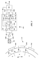
[0039] 図1を参照すると、物体124の移動に応答する回路例100は、物体124に伴う磁場に比例する差動信号104A,104B(即ち、磁場信号)を生成する磁場検知エレメント104を含む。磁場検知エレメント104は、ホール効果エレメント、磁気抵抗エレメント、または磁気トランジスタを含むことができるが、これらに限定されるのではない。
Referring to FIG. 1, an
[0040] 物体124は、回転するように構成されている物体、例えば、強磁性体のギアとすることができる。回路100は、磁場検知エレメント104から差動信号104A,104Bを受け取るように結合され、信号106A(または、磁場信号)を生成するように構成されている増幅器106を含むことができる。
[0040] The
[0041] また、回路100は、所定閾値検出器120も含む。実施形態の中には、所定閾値検出器120が、信号106Aを受け取るように結合され、信号122A(または、磁場信号)を生成するように構成されている増幅器122を含む場合もある。実施形態の中には、増幅器122が、自動利得制御(AGC)増幅器を含む場合、および/または回路100が自動オフセット調節(AOA)を含む場合もある。
[0041] The
[0042] 所定閾値検出器120は、磁場信号122Aに応答する第1入力128A、所定の閾値130に応答する第2入力128B、および所定閾値検出器出力信号140を供給する出力128Cを含むことができる。実施形態の中には、所定の閾値130が、基準電圧値、例えば、1.5ボルトを有する電気信号である場合もある。
[0042] The
[0043] また、回路100は、追跡閾値検出器110も含む。実施形態の中には、追跡閾値検出器110が、信号106Aを受け取るように結合され、信号112A(または磁場信号)を生成するように構成されている増幅器112を含む場合もある。実施形態の中には、増幅器112がAGC増幅器を含む場合、および/または回路100がAOAを含む場合もある。
[0043] The
[0044] 追跡閾値検出器110は、信号112Aを受け取るように結合され、信号112Aの正および負ピークを追跡して追跡信号117を生成するように構成されている追跡回路116を含むことができる。追跡閾値検出器110は、また、信号112Aに応答する第1入力118A、追跡信号117に関係する入力信号に応答する第2入力118B、および追跡閾値検出器出力信号145を供給する出力118Cを有する比較器118を含むことができる。
[0044] The
[0045] 本明細書において以下で詳細に説明する他の実施形態では、追跡閾値検出器110は、ピーク−ピーク比率検出器(図3)、ピーク基準検出器(図4Aおよび図4B)、ゼロ交差検出器(図5)、またはこれらの組み合わせを含む。
[0045] In other embodiments described in detail herein below, the
[0046] 実施形態の中には、検出器110,120が、物体124の回転移動を検出する回転検出器である場合もあり、一方他の実施形態の中には、検出器110,120が、物体124の並進移動を検出する並進検出器である場合もある。尚、検出器110,120は、前述した種類の物体移動の検出に限定されるのではなく、物体の回転および並進の組み合わせを含む、他の種類の物体移動も検出できることは注記してしかるべきである。
[0046] In some embodiments, the
[0047] 尚、信号104A,104B,106A,112A,122Aは全て磁場信号であり、全て、磁場検知エレメント104が受ける磁場を示すことは注記してしかるべきである。
[0047] It should be noted that the
[0048] また、回路100は出力信号選択器150も含むことができる。出力信号選択器150は、追跡閾値検出器出力信号145に応答する第1入力150Aと、所定閾値検出器出力信号140に応答する第2入力150Bとを有し、所定の条件に基づいて所定閾値検出器出力信号140または追跡閾値検出器出力信号145の内少なくとも1つに関係する回路出力信号155を生成するように構成されている。
[0048] The
[0049] 図8および図9に関連して以下で更に詳しく説明するが、実施形態の中には、所定の条件が較正時間期間の終了に対応する場合には、出力信号選択器150が、追跡閾値検出器110の較正時間期間中には所定閾値検出器出力信号140に関係する回路出力信号を生成し、較正時間期間の後には追跡閾値検出器出力信号145に関係する回路出力信号を生成するように構成されている場合もある。
[0049] As described in more detail below in connection with FIGS. 8 and 9, in some embodiments, if the predetermined condition corresponds to the end of the calibration time period, the
[0050] 実施形態の中には、所定の条件が、磁場信号106Aの所定のサイクル数、例えば、3サイクルである場合もある。
[0050] In some embodiments, the predetermined condition may be a predetermined number of cycles of the
[0051] 他の実施形態では、所定の条件が、所定閾値検出器出力信号140の所定のサイクル数、例えば、3サイクルである場合もある。
[0051] In other embodiments, the predetermined condition may be a predetermined number of cycles of the predetermined threshold
[0052] 更に他の実施形態では、所定の条件が、所定の時間、例えば、0.1秒に対応する場合もある。実施形態の中には、所定の時間が回転速度に関係がある場合、および/または回転後の所定の時間が検出される場合もある。回転速度が高い程、この時間は短くすることができるが、回転速度が低い程、この時間は長くすることができる。 [0052] In yet another embodiment, the predetermined condition may correspond to a predetermined time, eg, 0.1 seconds. In some embodiments, the predetermined time is related to the rotational speed and / or the predetermined time after rotation may be detected. The higher the rotational speed, the shorter this time can be, but the lower the rotational speed, the longer this time can be.
[0053] 他の実施形態では、回路100は、磁場検知エレメント104に結合され信号を処理する(信号106Aと同様でよい)ように構成されているAGCまたはAOAの内少なくとも1つを含む場合もある。これらの実施形態では、所定の条件は、AGCの条件、例えば、信号の3サイクルの間に変化しなかったAGCの利得、またはAOAの条件、例えば、AOAのオフセット値に対応する。
[0053] In other embodiments, the
[0054] 所定の条件は、以上で記載した条件に限定されるように解釈してはならず、種々のアルゴリズムに基づいて、追跡閾値検出器110を較正するときを決定し、適正な回転速度および/または方向情報を判定することもできる。
[0054] The predetermined conditions should not be construed to be limited to the conditions described above, but based on various algorithms, determine when to calibrate the
[0055] 配置の中には、磁場検知エレメント104が物体124の動き、例えば、ギアの強磁性ギア歯の動きに応答することができる場合もある。ギア124上のギア歯124A〜124Cが、この強磁性ギア歯を表している。この目的のために、固定磁石(図示せず)を、磁場検知エレメント104に近接して配置することができ、ギアが回転すると、ギア歯が、磁石によって生成される磁場を乱すことができる。しかしながら、他の配置では、磁場検知エレメント104は、磁石上にある磁性領域、例えば、リング・マグネット126上にある磁性領域126A〜126Cの移動に応答することができる。特定的な配置の中には、リング・マグネット126およびギア124が軸等によって互いに結合されている場合もある。これらの特定の配置では、リング・マグネット126は、磁場検知エレメント104に近接することができる。
[0055] In some arrangements, the magnetic
[0056] 磁場検知エレメント104は、リング・マグネット126の近接、そして具体的には、通過する磁性領域北(N)および南(S)126A〜126Cの近接に応答する。動作において、磁場検知エレメント104は、差動磁場信号104A,104Bを(そして、磁場信号106A,112A,122Aも)生成する。これらの差動磁場信号は、リング・マグネット126が回転するときは、通常繰り返しパターンを有し、このパターンの各ピーク(正および負)が磁性領域N,Sの1つと関連付けられる。
[0056] The magnetic
[0057] これより図2を参照すると、更に他の実施形態において、回路200は、第1所定閾値検出器220A、第2所定閾値検出器220B、および追跡閾値検出器210Aを含む。また、回路200は、第1対の磁場検知エレメント205Aも含むことができる。第1対の磁場検知エレメント205Aは、磁場検知エレメント204Aおよび磁場検知エレメント204Cを含み、物体224に伴う磁場に比例する差動磁場信号274A,274B,294A,294Bを供給するように動作する。実施形態の中には、回路200が増幅器206Aを含むことができる場合もある。増幅器206Aは、第1対の磁場検知エレメント205Aから差動信号274A,274Bを受け取るように結合され、信号276A(または、磁場信号)を生成するように構成されている。
[0057] Referring now to FIG. 2, in yet another embodiment, the circuit 200 includes a first
[0058] 実施形態の中には、第1所定閾値検出器220Aが増幅器222Aを含むことができる場合もある。増幅器222Aは、信号276Aを受け取るように結合され、信号272B(または、磁場信号)を生成するように構成されている。実施形態の中には、増幅器222AがAGC増幅器を含む場合、および/または回路100がAOAを含む場合もある。
[0058] In some embodiments, the first
[0059] 第1所定閾値検出器220Aは、比較器228Aを含むことができる。比較器228は、磁場信号272Bに応答する第1入力278A、所定の閾値230Aに応答する第2入力278B、および第1所定閾値検出器出力信号240Aを供給する出力278Cを有する。所定の閾値230Aは、複数の所定の閾値、例えば、第1所定の閾値および第2所定の閾値を含むことができる。
[0059] The first
[0060] また、回路200は、第2対の磁場検知エレメント205Bも含むことができる。第2対の磁場検知エレメント205Bは、磁場検知エレメント204Bおよび磁場検知エレメント204Cを含み、物体224に伴う磁場に比例する第2差動磁場信号284A,284B,294A,294Bを供給するように動作する。実施形態の中には、回路200が増幅器206Bを含むことができる場合もある。増幅器206Bは、第2対の磁場検知エレメント205Bから差動信号284A,284B,294A,294Bを受け取るように結合され、信号286A(または、磁場信号)を生成するように構成されている。
[0060] The circuit 200 may also include a second pair of magnetic
[0061] 更に他の実施形態では、第2所定閾値検出器220Bが増幅器222Bを含む。増幅器220Bは、信号286Aを受け取るように結合され、信号282B(または、磁場信号)を生成するように構成されている。更にまた他の実施形態では、増幅器222BがAGC増幅器を含む、および/または回路100がAOAを含む。
[0061] In yet another embodiment, the second
[0062] また、第2所定閾値検出器220Bは比較器228Bも含むことができる。比較器228Bは、磁場信号282Bに応答する第1入力288A、所定の閾値230Bに応答する第2入力288B、および第2所定閾値検出器出力信号240Bを供給する出力288Cを有する。実施形態の中には、検出器220Bの所定の閾値230Bが、検出器220Aの所定の閾値230Aと同一である場合もあり、一方他の実施形態の中には、所定の閾値230A,230Bが異なる場合もある。
[0062] The second
[0063] 実施形態の中には、回路200の追跡閾値検出器210Aが増幅器212Aを含む場合もある。増幅器212Aは、信号276Aを受け取るように結合され、信号272A(または、磁場信号)を生成するように構成されている。実施形態の中には、増幅器212AがAGC増幅器を含む場合、および/または回路100がAOAを含む場合もある。
[0063] In some embodiments, the tracking threshold detector 210A of the circuit 200 includes an
[0064] 追跡閾値検出器210Aは、追跡回路216Aを含むことができる。追跡回路216Aは、信号272Aを受け取るように結合され、信号272Aの正および負のピークを追跡し、追跡信号277Aを生成するように構成されている。また、追跡閾値検出器210Aは、比較器218Aも含むことができる。比較器218Aは、信号272Aに応答する第1入力278A、追跡信号277Aに関係する入力信号に応答する第2入力278B、および第1追跡閾値検出器出力信号245Aを供給する出力278Cを有する。
[0064] The tracking threshold detector 210A may include a
[0065] また、回路200は出力信号選択器250(図1に関連して説明した出力信号選択器150と同様でよい)も含むことができる。出力信号選択器250は、追跡閾値検出器出力信号245Aに応答する第1出力250A、第1閾値検出器出力信号240Aに応答する第2入力250B、および第2所定閾値検出器出力信号240Bに応答する第3入力250Cを有する。出力信号選択器250は、第1所定閾値検出器出力信号240A、追跡閾値検出器出力信号245A、または第2所定閾値検出器出力信号240Bの内少なくとも1つに関係する回路出力信号255を、所定の条件に基づいて生成するように構成されている。
[0065] The circuit 200 may also include an output signal selector 250 (which may be similar to the
[0066] 出力信号選択器250は、所定の条件に基づいて、信号245A,245B,240A,240Bを選択し、例えば、これらの信号の1つ以上に基づいて、速度および/または方向、および/または振動情報を決定するロジックを含む。例えば、信号のエッジ・レートが高い程、相対的に速い物体の移動に対応することができ、信号のエッジ・レートが低い程、相対的に遅い物体の移動に対応することができる。例えば、物体が回転ギアである実施形態では、信号周波数がギアの回転速度を示す。これらの信号の内2つの立ち上がりエッジおよび立ち下がりエッジの相対的位相シーケンスを用いて、物体の移動方向を判定することができる。尚、速度情報および/または方向情報を決定するロジックは、アナログ・ロジック、ディジタル・ロジック、および/または混合ロジックを含んでもよいことは言うまでもない。
[0066] The output signal selector 250 selects the
[0067] これらの実施形態では、第1所定閾値検出器出力信号240Aは、第1所定閾値検出器の位相を有し、第2所定閾値検出器出力信号240Bは、第2所定閾値検出器の位相を有する。第1および第2所定閾値検出器の位相間の差は、物体224の移動方向を示す。所定閾値検出器出力信号240A、閾値検出器の出力信号245A、または第2所定閾値検出器出力信号240Bの周波数はいずれも、物体224の回転速度に関係する。
[0067] In these embodiments, the first predetermined threshold detector output signal 240A has the phase of the first predetermined threshold detector, and the second predetermined threshold detector output signal 240B is the second predetermined threshold detector. Has a phase. The difference between the phases of the first and second predetermined threshold detectors indicates the direction of movement of the
[0068] 更に他の実施形態では、所定の条件は、第1または第2磁場信号276A,286Aの内一方の所定のサイクル数、例えば、3サイクルに関係する。 [0068] In yet another embodiment, the predetermined condition relates to a predetermined number of cycles, eg, 3 cycles, of one of the first or second magnetic field signals 276A, 286A.
[0069] 他の実施形態では、所定の条件は、第1または第2所定閾値検出器出力信号240A,240Bの内一方の所定のサイクル数、例えば、3サイクルに関係する。 [0069] In another embodiment, the predetermined condition relates to a predetermined number of cycles, eg, 3 cycles, of one of the first or second predetermined threshold detector output signals 240A, 240B.
[0070] 更に他の実施形態では、所定の条件は所定の時間に対応する。実施形態の中には、この所定の時間が回転速度に関係する場合、および/または回転後の所定時間を検出する場合もある。 [0070] In yet another embodiment, the predetermined condition corresponds to a predetermined time. In some embodiments, this predetermined time is related to the rotational speed and / or the predetermined time after rotation is detected.
[0071] 他の実施形態では、回路200はAGCを含む。このAGCは、第1または第2対の磁場検知エレメント205A,205Bの一方に結合され、第1または第2磁場信号(276A,286A)のそれぞれを処理するように構成されており、所定の条件は、AGCの条件、例えば、AGCの利得に対応する。任意に、回路200はAOAを含む。このAOAは、第1または第2対の磁場検知エレメント205A,205Bの一方に結合され、第1または第2磁場信号(276A,286A)のそれぞれを処理するように構成されており、所定の条件はAOAの条件に対応する。
[0071] In other embodiments, circuit 200 includes an AGC. The AGC is coupled to one of the first or second pair of magnetic
[0072] 再度図2を参照すると、他の実施形態では、回路200は、第1追跡閾値検出器210A、第2追跡閾値検出器210B、および第1所定閾値検出器220Aを含む。この実施形態では、回路200は、第1対の磁場検知エレメント205A、および第2対の磁場検知エレメント205Bを含む。
[0072] Referring again to FIG. 2, in another embodiment, the circuit 200 includes a first tracking threshold detector 210A, a second
[0073] 実施形態の中には、第2追跡閾値検出器210Bが増幅器212Bを含む場合もある。増幅器212Bは、信号286Aを(第2磁場検知エレメント205Bから)受け取るように結合され、信号282A(または、磁場信号)を生成するように構成されている。実施形態の中には、増幅器212BがAGC増幅器である場合、および/または回路100がAOAを含む場合もある。
[0073] In some embodiments, the second
[0074] 第2追跡閾値検出器210Bは、追跡回路216Bを含むことができる。追跡回路216Bは、信号282Aを受け取るように結合され、信号282Aの正および負のピークを追跡し、追跡信号277Bを生成するように構成されている。また、第2追跡閾値検出器210Bは、比較器218Bも含むことができる。比較器218Bは、信号282Aに応答する第1入力288A、追跡信号277Bに関係する入力信号に応答する第2入力288B、および第2追跡閾値検出器出力信号245Bを供給する出力288Cを有する。
[0074] The second
[0075] この実施形態では、回路200は出力信号選択器250(図1に関連して説明した出力信号選択器150と同様でよい)を含む。出力信号選択器250は、第1追跡閾値検出器出力信号245Aに応答する第1入力250A、第2追跡閾値検出器出力信号245Bに応答する第2入力250D、および第1所定閾値検出器出力信号240Aに応答する第3入力250Bを有する。出力信号選択器250は、第1追跡閾値検出器出力信号245A、第1所定閾値検出器出力信号240A、または第2追跡閾値検出器出力信号245Bの内少なくとも1つに関係する回路出力信号255を、所定の条件に基づいて生成するように構成されている。
[0075] In this embodiment, the circuit 200 includes an output signal selector 250 (which may be similar to the
[0076] この実施形態では、第1追跡閾値検出器出力信号245Aは、第1追跡閾値検出器位相を有し、第2追跡閾値検出器出力信号245Bは、第2追跡閾値検出器位相を有する。第1および第2追跡閾値検出器位相間の差が、物体224の移動方向を示す。第1追跡閾値検出器出力信号245A、第1所定閾値検出器出力信号240A、または第2追跡閾値検出器出力信号245Bの周波数はいずれも、物体224の回転速度に関係する。
[0076] In this embodiment, the first tracking threshold
[0077] 再度図2を参照すると、更に他の実施形態では、回路200は、第1追跡閾値検出器210A、第2追跡閾値検出器210B、第1所定閾値検出器220A、および第2所定閾値検出器220Bを含む。この実施形態では、出力信号選択器250は、第1追跡閾値検出器出力信号245Aに応答する第1入力250A、第1所定閾値検出器出力信号240Aに応答する第2入力250B、第2所定閾値検出器出力信号240Bに応答する第3入力250C、および第2追跡閾値検出器出力信号245Bに応答する第4入力250Dを含む。このような配置では、出力信号選択器250は、第1および第2追跡閾値検出器出力信号240A,245Bの組み合わせ、または第1および第2所定閾値検出器出力信号240A,240Bの組み合わせに対応する回路出力信号255を、所定の条件に基づいて供給するように構成されている。
[0077] Referring again to FIG. 2, in yet another embodiment, the circuit 200 includes a first tracking threshold detector 210A, a second
[0078] 更に他の実施形態では、所定の条件は、第1または第2磁場信号276A,286Aの一方の所定のサイクル数、例えば、3サイクルに関係する。 [0078] In yet another embodiment, the predetermined condition relates to a predetermined number of cycles of one of the first or second magnetic field signals 276A, 286A, eg, 3 cycles.
[0079] 更に他の実施形態では、所定の条件は、第1所定閾値検出器出力信号240A、第2所定閾値検出器出力信号240B、第1追跡閾値検出器出力信号245A、または第2追跡閾値検出器出力信号245Bの内1つの所定のサイクル数、例えば、3サイクルに関係する。
[0079] In yet other embodiments, the predetermined condition is a first predetermined threshold detector output signal 240A, a second predetermined threshold detector output signal 240B, a first tracking threshold
[0080] 更に他の実施形態では、第1または第2所定閾値検出器220A,220Bの少なくとも1つが、シュミット・トリガを含む。
[0080] In yet another embodiment, at least one of the first or second
[0081] 尚、本回路は、以上で述べた構成に限定されるのではなく、多数の追跡閾値検出器(即ち、2つよりも多い追跡閾値検出器)および/または多数の所定閾値検出器(即ち、2つよりも多い所定閾値検出器)を含む、他の所望の構成も包含してもよいことは、当業者には明白なはずである。 [0081] It should be noted that the present circuit is not limited to the configuration described above, but a number of tracking threshold detectors (ie, more than two tracking threshold detectors) and / or a number of predetermined threshold detectors. It should be apparent to those skilled in the art that other desired configurations including (ie, more than two predetermined threshold detectors) may be included.
[0082] 回路100,200の動作については、図7から図9に関連して以下で説明する。
[0082] The operation of the
[0083] これより図3を参照すると、図1の追跡回路116としての使用に適しているピーク−ピーク比率検出器26が示されている。ピーク−ピーク比率検出器26は、図1の比較器118のような、比較器428に結合されている。図1の信号112Aのような磁場信号18が、入力として検出器26に供給される。
[0083] Referring now to FIG. 3, a peak-to-
[0084] 磁場信号18は、第1比較器400の比反転入力と、第2比較器404の反転入力とに印加される。比較器400および404の出力信号は、それぞれ、入力信号GT_PDAC458およびLT_NDAC461を更新コントローラ409に供給し、更新コントローラ409は、図示のように、制御信号をカウンタ414および430に供給する。
The
[0085] 更新コントローラ409は、カウント方向を制御するために、p_updn信号463をカウンタ414のUPDN(アップ/ダウン)入力に供給する。明白になるであろうが、p_updn信号463は通常ではカウンタ414を増加するようにカウントさせる。しかしながら、一定の条件の下では、p_updn信号463は、あるクロック・サイクルの間カウンタ414を減少するようにカウントさせる。カウンタ414はシステム・クロック信号CLKによって駆動される(clock)。p_hold信号465がカウンタ414のHOLD入力に結合されている。カウンタ出力は、HOLD入力信号が第1論理レベルにあるときには、一定に維持され(即ち、カウンタはディスエーブルされる)、HOLD入力信号が第2論理レベルにあるときには解放される(即ち、カウンタはイネーブルされる)。カウンタ414は、HOLD入力がローのときにイネーブルされる6ビット・カウンタとするとよい。
The
[0086] カウンタ414の出力は、正ディジタル/アナログ変換器(PDAC)403の入力に結合されている。PDAC信号402を供給するために、PDAC403がバッファ424によってバッファされ、PDAC信号402は、磁場信号18の正ピークを追跡する電圧(即ち、追跡信号)であればよい。
The output of
[0087] 比較器414、カウンタ414、PDAC403、およびバッファ424は、検出器回路の「正部分」を構成する。検出器26の「負部分」も、図示のように、同様に配置される。具体的には、更新コントローラ409が、カウント方向を制御するために、n_updn信号466をカウンタ430のUPDN入力に供給する。明らかになるであろうが、n_updn信号466は通常ではカウンタ430を減少するようにカウントさせる。しかしながら、一定の条件の下では、n_updn信号466は、あるクロック・サイクルの間カウンタ430を増加するようにカウントさせる。カウンタ430は、システム・クロック信号CLKによって駆動される。n_hold信号468が、カウンタ430のHOLD入力に結合されている。カウンタ出力は、HOLD入力信号が第1論理レベルにあるときには一定に保持され(即ち、カウンタはディスエーブルされる)、HOLD入力信号が第2論理レベルにあるときには解放される(即ち、カウンタはイネーブルされる)。カウンタ430は、HOLD入力がローのときにイネーブルされる6ビット・カウンタとするとよい。
[0087]
[0088] カウンタ430の出力は、負ディジタル/アナログ変換器(NDAC)405の入力に結合されている。NDAC信号406を供給するために、NDAC405がバッファ436によってバッファされ、NDAC信号406は、磁場信号18の負ピークを追跡する電圧(即ち、追跡信号)であればよい。
The output of
[0089] バッファされたPDACおよびNDAC信号402、406は、ピーク−ピーク閾値信号THRESHHIおよびTHRESHLOを生成するために、直列結合された抵抗器408,412,416を備える抵抗分圧器(resistor divider)に結合される。これについては、以下で図8に関連して更に詳しく説明する。
[0089] The buffered PDAC and NDAC signals 402, 406 are fed into a resistor
[0090] 閾値信号THRESHHIおよびTHRESHLOの各々は、PDACおよびNDAC電圧間の差の比率である。即ち、言い換えると、ピーク−ピーク磁場信号18の比率である。図8に関連して以下で更に詳しく説明するが、一実施形態では、上位閾値440はピーク−ピーク信号のほぼ75%であり、下位閾値444はピーク−ピーク信号のほぼ25%である。尚、他の比率でも適することもあることは認められよう。スイッチ424aおよび424bが、図示のように、これらの閾値レベルの一方を比較器428に印加するように配置および制御される。スイッチ424bは、POSCOMP信号によって制御される。具体的には、スイッチ424aは、POSCOMP信号の反転バージョン、即ち、POSCOMPNによって制御される。更に、磁場信号18は比較器428の比反転入力に印加される。
[0090] Each of the threshold signals THRESHHI and THRESHLO is the ratio of the difference between the PDAC and NDAC voltages. That is, in other words, the ratio of the peak-peak
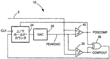
[0091] これより図4を参照すると、図1の追跡閾値検出器110としての使用に適しているピーク基準検出器10が示されている。この検出器10は、磁場信号2を追跡するために1つのディジタル/アナログ変換器(DAC)28を用いる。磁場信号2は、追跡比較器20の反転入力に結合され、追跡比較器20は、図示のように、その非反転入力においてDAC28の出力信号PEAKDAC(即ち、追跡信号)を受け取る。磁場信号2は、更に、図1の比較器118のような比較器40の反転入力に結合されている。比較器40は、その非反転入力において、PEAKDAC信号を受け取り、検出器出力信号POSCOMPを生成する。比較器40は、内部ヒステリシス、ここでは、約100mVを有するので、POSCOMP出力信号は、磁場信号2が約100mVだけPEAKDAC信号を超過すると、状態を変化させる。比較器20の出力信号COMPOUTは、排他的OR(XOR)ゲート36に結合され、XORゲート36は、加えて、POSCOMP信号も受け取り、HOLD入力信号をアップ/ダウン・カウンタ24に供給する。カウンタ24は、更に、クロック信号CLKおよびPOSCOMP信号にも応答して、カウンタ24が増加するようにカウントするのかまたは減少するようにカウントするのか制御する。カウンタ24の出力信号は、DAC28によって追跡PEAKDAC信号に変換される。
[0091] Referring now to FIG. 4, a
[0092] 図4Bに示すように、磁場信号2が、比較器20の小さなヒステリシスだけPEAKDAC信号を超過するときにはいつでも、COMPOUT信号は論理ハイ・レベルに遷移する。カウンタ24へのHOLD入力は、排他的OR(XOR)ゲート36に結合され、XORゲート36は、COMPOUTに結合され、更にPOSCOMP信号を受け取る。一旦カウンタ24が1ステップ上にカウントすると、COMPOUT信号はローになり、信号が比較器20の小さなヒステリシスだけ再度超過するまで、カウンタ値を保持させる。時点t1において発生するように、磁場信号が正ピークに達すると、PEAKDAC信号は信号2よりも高くなり、これによって、比較器40のヒステリシスが克服されるまで、カウンタ24へのHOLD入力をアサートさせておく。これが発生するのは、時点t2の直前において、POSCOMP信号がローになるときである。このように、信号の正および負のピークがPEAKDAC信号によって追跡され、検出器出力信号POSCOMPは、比較器40のヒステリシス量よりも多く信号がPEAKDAC信号と異なるとき(時点t0およびt2において発生する)に遷移する。
[0092] As shown in FIG. 4B, whenever the
[0093] これより図5を参照すると、いわゆる「ゼロ交差検出器」500である、追跡および比較回路を、図1の追跡回路116および比較器118と比較することができる。ここでは、増幅器506が2つの磁場検知エレメント502,504から信号502A,502B,504A,504Bを受け取るように結合されている。増幅器506は、バンド・パス・フィルタ(BPF)508に結合される差動磁場信号506A,506Bを生成するように構成されている。磁場信号506A,506Bは、図1の磁場信号106Aに相応する。BPF508は、差動フィルタ信号(differential filtered signal)508A,508Bを生成するように構成されている。比較器528は、差動フィルタ信号508A,508Bを受け取るように結合され、動き信号POSCOMP510Aを生成するように構成されている。
[0093] Referring now to FIG. 5, the tracking and comparison circuit, a so-called “zero crossing detector” 500, can be compared to the
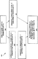
[0094] これより図6を参照すると、物体の移動を検出する方法600は、602において、物体に伴う磁場に比例する磁場信号を生成するステップ、604において磁場信号の正および負のピークを追跡するために磁場信号に応答する追跡信号を生成するステップ、606において、磁場信号および所定の閾値に応答して所定の閾値出力信号を生成するステップ、608において、磁場信号および追跡信号に応答して追跡閾値出力信号を生成するステップ、並びに、610において、所定の閾値出力信号または追跡閾値出力信号から選択した1つに関係する総合出力信号を、所定の条件に基づいて供給するステップを含む。
[0094] Referring now to FIG. 6, a
[0095] 尚、当該方法600は、回路において実現することができ、例えば、図1に関連して説明した回路100、または図2に関して説明した回路200において実現できることは認められてしかるべきである。更に、方法ステップ(即ち、ステップ602,604,606,608,610)の内1つ以上をプロセッサにおいて実現することもでき、具体的には、実行のためにメモリからプロセッサにロードするコンピュータ・ソフトウェア命令として実現することができる。
[0095] It should be appreciated that the
[0096] 代替として、以上の方法ステップの内1つ以上を、ディジタル信号プロセッサ回路または特定用途集積回路(ASIC)のような機能的に等価な回路によって実行することもできる。本方法は、いずれかの特定のプログラミング言語のシンタックス(syntax)を図示するのではない。むしろ、本方法は、当業者が回路を製作するため、または本明細書において記載する技法の少なくとも一部を実現するために必要とされる処理を実行するコンピュータ・ソフトウェアを生成するために必要な情報を当業者に例示する。尚、記載するブロックの特定のシーケンスは例示に過ぎず、本発明の主旨から逸脱することなく様々に変更可能であることは、当業者には認められよう。 [0096] Alternatively, one or more of the above method steps may be performed by a functionally equivalent circuit such as a digital signal processor circuit or an application specific integrated circuit (ASIC). The method does not illustrate the syntax of any particular programming language. Rather, the method is necessary for a person skilled in the art to generate computer software that performs the processing required to produce a circuit or to implement at least some of the techniques described herein. The information is illustrated to those skilled in the art. It will be appreciated by those skilled in the art that the particular sequence of blocks described is exemplary only and that various changes can be made without departing from the spirit of the invention.
[0097] 方法600の他の実施形態では、所定の条件は、磁場信号の所定のサイクル数に関係する。非限定的な一例では、プロセッサは磁場信号を処理して、磁場信号の所定のサイクル数(例えば、磁場信号の3サイクル)を認識することができる。プロセッサは、所定の条件が満たされた(即ち、磁場信号の3サイクルが発生した)と判断し、所定閾値出力信号または追跡閾値出力信号から1つを選択することによって、総合出力信号を供給する。一構成では、プロセッサは、所定の条件が認められる前には(即ち、プロセッサが磁場信号の所定のサイクル数を認識する前)所定閾値出力信号に関係する総合出力信号を供給し、所定の条件が認められた後には(即ち、プロセッサが磁場信号の所定のサイクル数を認識した後)追跡閾値出力信号に関係する総合出力信号を供給する。
[0097] In other embodiments of the
[0098] 方法600の他の実施形態では、所定の条件は、所定閾値出力信号の所定のサイクル数に関係する。非限定的な一例では、プロセッサは所定閾値出力信号を処理して、この信号の所定のサイクル数を認識することができる(たとえば、所定閾値出力信号の3サイクル)。プロセッサは、所定の条件が満たされている(即ち、所定閾値出力信号の3サイクルが過ぎた)と判断し、所定閾値出力信号または追跡閾値出力信号から一方を選択することによって総合出力信号を供給する。一構成では、プロセッサは、所定の条件が認められる前には(即ち、プロセッサが所定閾値出力信号の3サイクルを認識する前)、所定閾値出力信号に関係する総合出力信号を供給し、所定の条件が認められた後には(即ち、プロセッサが所定閾値出力信号の3サイクルを認識した後)、追跡閾値出力信号に関係する総合出力信号を供給する。
[0098] In other embodiments of the
[0099] 方法600の更に他の実施形態では、所定の条件は所定の時間に対応する。この所定の時間は、任意に、図1に関連して説明した回路100、または図2に関連して説明した回路200のような回路の較正時間に関係付けることができる。以下で更に詳しく説明するが、較正時間は、差動信号のオフセットおよび利得調節に関係する較正期間に対応するのでもよい。
[0099] In yet another embodiment of the
[0100] したがって、更に他の実施形態では、方法600は、較正時間期間中に所定閾値出力信号に関係するように総合出力信号を選択し、較正時間期間の後、追跡閾値出力に関係するように総合出力信号を選択するステップを含む。このように、所定の条件は、較正時間期間の終了に対応する。
[0100] Thus, in yet another embodiment, the
[0101] 非限定的な一例では、プロセッサは、所定時間(例えば、実施形態の中には、この時間が目標回転速度に関係する場合もある)に基づいて、所定閾値出力信号または追跡閾値出力信号から選択した1つを供給する。更に他の実施形態では、所定の時間は、移動を検出しようとする物体が移動し始めた時刻、または回路(回路200と同一または同様でよい)が起動したまたは電源投入した時刻に関して定められる。非限定的な一例では、物体は、エンジンの回転軸に結合された回転ギアである。この回転ギアは、エンジン構成部品の動き(更に特定すれば、動きの速度および方向)を検出するために用いることができる。非限定的な一例として、車両では、これは、クランクシャフト、排気カムシャフト、吸気カムシャフト、ピストン、接続ロッド、弁、変速ギア、車輪等の動き検出を含むことができる。 [0101] In one non-limiting example, the processor may generate a predetermined threshold output signal or tracking threshold output based on a predetermined time (eg, in some embodiments, this time may relate to a target rotational speed). Supply one selected from the signals. In yet another embodiment, the predetermined time is defined with respect to the time at which the object whose movement is to be detected begins to move, or the time at which the circuit (which may be the same as or similar to circuit 200) is activated or turned on. In one non-limiting example, the object is a rotating gear that is coupled to the rotating shaft of the engine. This rotating gear can be used to detect the movement of engine components (more specifically, the speed and direction of movement). As a non-limiting example, in a vehicle, this can include motion detection of crankshafts, exhaust camshafts, intake camshafts, pistons, connecting rods, valves, transmission gears, wheels, and the like.
[0102] 尚、所定の時間は種々のタイミング・イベントに関して定められてもよいことは注記してしかるべきである。例えば、前述したエンジンを中立状態に入れると、その間エンジン構成部品は静止状態(またはアイドル状態)となり、移動の検出は望まれないか、または必要ない。しかしながら、一旦エンジンを始動し構成部品が動作し始めたならば、プロセッサは経過時間を追跡し、所定の時間に達するまで所定閾値出力信号を供給し、その後、プロセッサは追跡閾値出力信号を供給する。 [0102] It should be noted that the predetermined time may be defined for various timing events. For example, when the engine described above is put into a neutral state, the engine components are stationary (or idle) during that time, and detection of movement is not desired or necessary. However, once the engine is started and the component begins to operate, the processor tracks the elapsed time and provides a predetermined threshold output signal until a predetermined time is reached, after which the processor provides a tracking threshold output signal. .
[0103] 他の実施形態では、方法600は、AGCを用いて磁場信号を処理するステップを含む。ここで、所定の条件はAGCの条件に対応し、例えば、AGCが更新するのを停止する時点に対応する。更に他の実施形態では、方法600は、AOAを用いて磁場信号を処理するステップを含み、所定の条件は、AOAの条件、例えば、オフセット値に対応する。
[0103] In other embodiments, the
[0104] これより図7を参照すると、グラフ700は任意の時間単位とした目盛りを付した横軸と、任意の電圧単位とした目盛りを付した縦軸とを有する。グラフ700の一部700Aは、例えば、図2の磁場信号272Bを表す時間可変磁場信号772Aを含む。磁場信号772Aは、物体の移動に伴う磁場に応答する。この物体は、図2に関連して説明した物体224と同様でよい。
[0104] Referring now to FIG. 7, the
[0105] グラフ700の他の部分700Cは、例えば、図2の所定閾値検出器220Aから出力される所定閾値検出器出力信号240Aを表す、所定閾値検出器出力信号740Aを含む。動作において、所定閾値検出器出力信号740Aは、比較器(図2に関連して説明した比較器228Aと同様でよい)の出力を表す。この比較器は、第1入力において磁場信号772Aに結合され、第2入力において所定の閾値Thを表す基準電圧に結合されている。磁場信号772は、信号772Aのピークに向かうときおよびピーク(このようなピークの例を参照番号771で示す)から離れるときに所定の閾値Thと交差して(ここでは、時点773A,773B)、比較器の出力を第1状態(この一例を参照番号776で示す)から第2状態(この一例を参照番号774で示す)に変化させ、次いで再度第1状態776に変化させる。所定閾値検出器出力信号740Aの第1および第2状態776,774は、正および負のエッジ(これらの例を、それぞれ、参照番号775Aおよび775Bで示す)によって分離されている。同じまたは異なる実施形態では、所定の閾値Thは、第1所定閾値(即ち、時点773Aにおける所定の閾値)と、第2所定閾値(例えば、時点773Cにおける所定の閾値)を含み、これらが第1および第2状態776,774を誘発する。
[0105] The
[0106] 実施形態の中には、所定閾値検出器出力信号740Aの第1および第2状態776,774が、物体に伴う時間可変磁場に応答し、1対の磁場検知エレメント(図2に関連して説明した第1対の磁場検知エレメント205Aと同様でよい)によって検知される場合がある。この1対の磁場検知エレメントは、信号772Aを供給する。磁場信号772Aは、物体が移動して磁場検知エレメントを通過するとき(そして、更に特定すれば、物体224のギア歯224A,224B,224Cのような物体の部分が移動して磁場検知エレメントを通過するとき)に生成する時間可変磁場に関係するパターン(ここでは、簡略化のために正弦波パターンにして示す)を示す。所定閾値検出器出力信号740Aの第1および第2状態776,774は、このパターンのサイクルをエンコードすると言うことができ、このようにして、このパターンを誘発する物体の移動を示す。実施形態の中には、第2状態774が、物体の部分(北極性および南極性を有するギア歯の一部のような部分)が移動して磁場検知エレメントを通過するときにおけるこれらの部分に関係する場合もある。実施形態の中には、磁場信号772Aが飽和する場合もある(その例を参照番号779Aおよび779Bで示す)。
[0106] In some embodiments, the first and
[0107] グラフ700の他の部分700Bは、例えば、図2の磁場信号282Bを表す時間可変磁場信号772Bを含む。磁場信号772Bは、図2に関連して説明した物体224と同様に、物体の移動に伴う磁場に応答する。
[0107] Another portion 700B of the
[0108] グラフ700(部分700Cにおいて)は、例えば、図2の所定閾値検出器220Bから出力された所定閾値検出器出力信号240Bを表す所定閾値検出器出力信号740Bを含む。動作において、所定閾値検出器出力信号740Bは、比較器(図2に関連して説明した比較器228Bと同様でよい)の出力を表す。この比較器は、第1入力において磁場信号772Bに結合され、第2入力において、所定の閾値Thを表す基準電圧に結合されている。磁場信号772Bは、信号772Bのピークに向かうときおよびピークから離れるとき(このようなピークの例を参照番号781で示す)に所定の閾値Thを交差して(ここでは、時点783A,783B)、比較器の出力を第1状態(その一例を参照番号786で示す)から第2状態(その一例を参照番号784で示す)に変化させ、更に再度状態776に変化させる。所定閾値検出器出力信号740Bの第1および第2状態786,784は、正および負のエッジ(その例を、それぞれ、参照番号785Aおよび785Bで示す)によって分離されている。
[0108] The graph 700 (in the
[0109] 実施形態の中には、所定閾値検出器出力信号740Bの第1および第2状態786,784が、物体に伴う時間可変磁場に応答する場合もある。この時間可変磁場は、1対の磁場検知エレメント(図2に関連して説明した第2対の磁場検知エレメント205Bと同様でよい)によって検知される。この1対の磁場検知エレメントは信号772Bを供給する。磁場信号772Bは、物体が移動して磁場検知エレメントを通過するときに(そして、更に特定すれば、物体224のギア歯224A,224B,224Cのような物体の部分が移動して磁場検知エレメントを通過するときに)時間可変磁場に関係するパターン(ここでは簡略化のために正弦波パターンにして示す)を示す。所定閾値検出器出力信号740Bの第1および第2状態786,784は、このパターンのサイクルをエンコードすると言うことができ、このようにして、パターンを誘発する物体の移動を示す。実施形態の中には、第2状態が、物体の部分(北極性および南極性を有するギア歯の一部のような部分)が移動して磁場検知エレメントを通過するときのこれらの部分に関係する場合もある。
[0109] In some embodiments, the first and
[0110] 所定閾値検出器出力信号740Aのエッジ・レートまたは周期は、物体の移動速度を示す。言い換えると、エッジ・レートが高い程、相対的に速い物体移動に対応し、エッジ・レートが低い程、相対的に遅い物体移動に対応する。物体が回転ギアである実施形態では、信号周波数がギアの回転速度を示す。
[0110] The edge rate or period of the predetermined threshold
[0111] 図7において、三角形アイコン777の向きは、物体の移動方向を示す。グラフ700において見ることができるように、これらのアイコンは全て紙面の右側に向けられており、グラフに示す時間全体において物体が同じ方向に移動していることを示す。更に、所定閾値検出器出力信号740A,740Bは、相対的な位相を有すると言うことができる。立ち上がりおよび立ち下がりエッジの相対的位相シーケンスは、物体の移動方向を判定するために用いることができる。物体が回転ギアである実施形態では、アイコンの方向は、ギアの時計回りまたは反時計回り方向の回転移動を示す。
In FIG. 7, the direction of the triangle icon 777 indicates the moving direction of the object. As can be seen in the
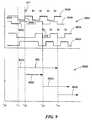
[0112] これより図8を参照すると、グラフ800は、任意の時間単位とした目盛りを付した横軸と、任意の電圧単位とした目盛りを付した縦軸とを有する。グラフ800の一部800Aは、例えば、図2の磁場信号272Aを表す時間可変磁場信号872Aを含む。磁場信号872Aは、物体の移動に伴う磁場に応答する。この物体は、図2に関連して説明した物体224と同様でよい。通常の動作では、PDAC信号874Aは、図3に関連して説明したPDAC信号402を表すことができ、正のピーク(その一例を参照番号871Aで示す)を取り込んで追跡することができる。PDAC信号874Aは、サイクルにおける種々の時点の間、例えば、時点t1およびt2の間における磁場信号872Aを追跡しようとして、最終的に時点t5付近における磁場信号872Aの正のピークに達する。これは、磁場信号872Aの約3サイクル以内(または、検出目標物の回転速度に関係付けることができる時間期間にわたって)であるとよい。PDAC信号874Aは他の時点では一定である(hold)。
Referring now to FIG. 8, the
[0113] 尚、PDAC信号874Aは、磁場信号872Aの正ピークに達する前の時間(破線のボックス890Aで示す時間のような)に生成されるが、精度が低く、真の動き検出情報を表さないので、図8には示されていないことは、注記してしかるべきである。また、実施形態の中には、PDAC信号874Aが、磁場信号872Aの正ピークの直前(例えば、正ピーク871Aの直前)に解放され、ピークを取り込んだときに磁場信号872Aを追跡する場合もあることも注記してしかるべきである。
Note that the
[0114] 同様に、NDAC信号876Aは、図3に関連して説明したNDAC信号406を表すことができ、負のピーク(その一例を参照番号881Aで示す)を取り込み追跡することができる。NDAC信号876Aは、サイクルにおける種々の時点の間、例えば、時点t3およびt4の間における磁場信号872Aを追跡しようとして、最終的に時点t6付近における磁場信号872Aの負のピークに達する。これも、磁場信号872Aの約3サイクル以内であるとよい。PDAC信号876Aは他の時点では一定である(hold)。
[0114] Similarly,
[0115] 尚、NDAC信号876Aは、磁場信号872Aの負のピークに達する前の時間(破線のボックス892Aで示す時間のような)に生成されるが、精度が低く、真の動き検出情報を表さないので、図8には示されていないことは、注記してしかるべきである。また、実施形態の中には、NDAC信号876Aが、磁場信号872Aの負のピークの直前(例えば、負ピーク881Aの直前)に解放され、ピークを取り込んだときに磁場信号872Aを追跡する場合もあることも注記してしかるべきである。
[0115] The
[0116] グラフ800の他の部分800Bは、例えば、図2の磁場信号282Aを表す時間可変磁場信号872Bを含む。磁場信号872Bは、図2に関連して説明した物体224と同様でよい、物体の移動に伴う磁場に応答する。通常の動作では、PDAC信号874Bは、図3に関連して説明したPDAC信号402を表すことができ、正のピーク(その一例を参照番号871Bで示す)を取り込んで追跡することができる。PDAC信号874Bは、サイクルにおける種々の時点の間、例えば、時点t7およびt8の間において磁場信号872Bを追跡しようとして、最終的に時点t11の付近で磁場信号872Aの正のピークに達する。これは、磁場信号872Aの約3サイクル以内であるとよい。PDAC信号874Bは、他の時点では一定である。
[0116] The other portion 800B of the
[0117] 尚、PDAC信号872Bは、磁場信号872Bの正のピークに達する前の時間(破線のボックス80Bで示す時間のような)に生成されるが、精度が低く、真の動き検出情報を表さないので、図8には示されていないことは、注記してしかるべきである。また、実施形態の中には、PDAC信号872Bが、磁場信号872Bの正のピークの直前(例えば、正のピーク871Bの直前)に解放され、ピークを取り込んだときに磁場信号872Bを追跡する場合もあることも注記してしかるべきである。
[0117] Note that the PDAC signal 872B is generated at a time (such as the time indicated by the dashed box 80B) before reaching the positive peak of the magnetic field signal 872B, but the accuracy is low and the true motion detection information is displayed. It should be noted that it is not shown in FIG. Also, in some embodiments, the PDAC signal 872B is released immediately before the positive peak of the magnetic field signal 872B (eg, immediately before the
[0118] 同様に、NDAC信号876Bは、図3に関連して説明したNDAC信号406を表すことができ、負ピーク(その一例を参照番号881Bで示す)を取り込んで追跡することができる。NDAC信号876Bは、サイクルにおける種々の時点の間、例えば、時点t9およびt10の間における磁場信号872Bを追跡しようとして、最終的に、時点t12の付近で磁場信号872Bの負のピークに達する。これも、磁場信号872Bの約3サイクル以内であるとよい。NDAC信号876Bは、他の時点では一定である。 [0118] Similarly, NDAC signal 876B may represent NDAC signal 406 described in connection with FIG. 3, and may capture and track negative peaks (an example of which is indicated by reference numeral 881B). NDAC signal 876B during the various times in the cycle, for example, in an attempt to track the magnetic field signal 872B in between times t 9 and t 10, finally, around a time point t 12 to a negative peak of the magnetic field signal 872B Reach. This may also be within about 3 cycles of the magnetic field signal 872B. NDAC signal 876B is constant at other times.
[0119] 尚、NDAC信号876Bは、磁場信号872Bの負ピークに達する前の時間(破線のボックス892Bによって示される時間のような)に生成されるが、精度が低く、真の動き検出情報を表さないので、図8には示されていないことは、注記してしかるべきである。また、実施形態の中には、NDAC信号876Bが、磁場信号872Bの負のピークの直前(例えば、負ピーク881Bの直前)に解放され、ピークを取り込んだときに磁場信号872Bを追跡する場合もあることも注記してしかるべきである。 Note that the NDAC signal 876B is generated at a time (such as the time indicated by the dashed box 892B) before reaching the negative peak of the magnetic field signal 872B, but the accuracy is low and the true motion detection information is It should be noted that it is not shown in FIG. Also, in some embodiments, the NDAC signal 876B is released just before the negative peak of the magnetic field signal 872B (eg, just before the negative peak 881B) and tracks the magnetic field signal 872B when the peak is captured. It should also be noted that there is.
[0120] グラフ800の他の部分800Cは、例えば、図2の追跡閾値検出器210Aから出力される追跡閾値検出器出力信号245Aを表す追跡閾値検出器出力信号745Aを含む。動作において、追跡閾値検出器出力信号745Aは、比較器(図2に関連して説明した比較器218Aと同様でよい)の出力を表す。この比較器は、第1入力において磁場信号872Aに結合され、第2入力において追跡信号に結合されている。この追跡信号は、追跡回路216Aから出力され図2に関連して説明した追跡信号277Aと同様でよい。
[0120] Another
[0121] 追跡閾値出力信号745Aは、磁場信号872Aの正および負ピークとそれぞれ一致するエッジ747A,747Bを有する。図8において分かるのは、ある時点(例えば、t6の付近)では、追跡閾値検出器出力信号745Aのエッジ間が、磁場信号872Aのピーク間の広さと一致することであり、この時点において、追跡閾値検出器が磁場信号872Aのピークに対して較正されたと言うことができる(即ち、追跡閾値検出器出力信号745Aは、精度高く磁場信号872Aの正および負のピークを追跡する)。追跡閾値検出器出力信号745Aは、磁場信号872Aのピーク間の広さに一致する前の時間(破線のボックス893によって示す時間のような)に生成されるが、用いられないので、図8では示されていない。
[0121] The tracking
[0122] また、グラフ800の部分800Cは、例えば、図2の追跡閾値検出器210Bから出力された追跡閾値検出器出力信号245Bを表す追跡閾値検出器出力信号745Bも含む。動作において、追跡閾値検出器出力信号745Bは、比較器(図2に関連して説明した比較器218Bと同様でよい)の出力を表す。この比較器は、第1入力において磁場信号872Bに結合され、第2入力において、追跡信号に結合されている。この追跡信号は、図2に関連して説明した追跡回路216Bから出力される追跡信号277Bと同様でよい。
[0122] The
[0123] 前述の信号745Aと同様に、追跡閾値出力信号745Bは、磁場信号872Bの正および負のピークとそれぞれ一致するエッジ757A,757Bを有する。図8において分かるのは、ある時点において(例えば、t12の付近で)、追跡閾値出力信号745Bのエッジ間が、磁場信号872Bのピーク間の広さに対応することであり、この時点において、追跡閾値検出器が磁場信号872Bに対して較正されたと言うことができる(即ち、追跡閾値検出器出力信号745Bは精度高く磁場信号872Bの正および負のピークを追跡する)。追跡閾値出力信号745Bは、それが磁場信号872Bのピーク間の広さと一致する前の時間(例えば、破線ボックス893によって示される時間)に生成されるが、用いられないので図8には示されていない。
[0123] Similar to signal 745A described above, tracking threshold output signal 745B has
[0124] 図8において、三角形のアイコン(その一例を参照番号877で示す)は物体の移動速度および方向を示す。追跡閾値検出器出力信号745A、745Bのエッジ・レートまたは周期は、物体の移動速度を示す。言い換えると、エッジ・レートが高い程、相対的に速い物体移動に対応し、エッジ・レートが低い程、相対的に遅い物体移動に対応する。物体が回転ギアである実施形態では、信号の周波数はギアの回転速度を示す。
In FIG. 8, a triangular icon (an example of which is indicated by reference numeral 877) indicates the moving speed and direction of the object. The edge rate or period of the tracking threshold
[0125] 図8において、三角形アイコン877の向きは、物体の移動方向を示す。グラフ800において見ることができるように、第1の三角形アイコン877Aは、想像の輪郭で示されており、方向出力が生成されるが、精度が低いのでこの方向情報は所定閾値検出器から生成するとよいことを示す。他のアイコン(例えば、参照番号877Bで示すアイコン)は、紙面の右側に向けられている。図2に関連して先に説明した回路配置と同一または同様でよいが、第1および第2追跡閾値検出器出力信号745A,745Bは、オフセット磁場検知エレメント(磁場検知エレメント204A,204Bのような)に対する物体の移動に応答する。したがって、信号745A,745Bの立ち上がりおよび立ち下がりエッジの相対的位相シーケンスは、物体の移動方向を表す。
In FIG. 8, the direction of the triangle icon 877 indicates the moving direction of the object. As can be seen in the
[0126] 連続するエッジ760Cおよびエッジ760Bは、物体の移動方向を精度高く判定し更新するために用いることができる(三角形アイコン877Bおよび他の連続するアイコンによって見ることができるように)。物体が回転ギアである実施形態では、アイコンの方向は、ギアの時計回り方向または反時計回り方向の回転移動を示す。 [0126] The continuous edges 760C and 760B can be used to accurately determine and update the direction of movement of the object (as can be seen by the triangle icon 877B and other consecutive icons). In embodiments where the object is a rotating gear, the direction of the icon indicates a rotational movement of the gear in a clockwise or counterclockwise direction.
[0127] 再度図7および図8を参照すると、所定閾値検出器出力信号(740A,740B)を用いて、時点t0における回路の起動または電力投入に近い時点で、正しい物体移動情報(具体的には、物体の移動方向)を生成できることが分かる。例えば、所定閾値検出器出力信号(740A,740B)を用いた正しい物体移動方向情報は、時点t0の後に時点t01において直ちに生成することができる。追跡閾値検出器出力信号(745A,745B)を用いた正しい物体移動方向情報は、時点t01よりも後に、時点t02において生成することができる。時間差の少なくとも一部は、追跡閾値検出器を較正するために必要な時間に帰することができる。対照的に、所定閾値検出器は、磁場信号が所定の閾値(例えば、773A,773Bまたは773A,773C)を交差するときにはいつでも物体移動方向情報を生成することができる。これは、回路の起動または電力投入後比較的直ぐに行うことができる。 [0127] Referring to FIGS. 7 and 8 again, using a predetermined threshold detector output signals (740A, 740B), when close to the circuit of the start or power up at time t 0, the correct object movement information (specifically It can be seen that the moving direction of the object can be generated. For example, the predetermined threshold detector output signals (740A, 740B) correct object movement direction information using the can immediately be generated at time t 01 after the time t 0. Tracking threshold detector output signals (745A, 745B) correct object movement direction information with the later than time t 01, can be generated at time t 02. At least a portion of the time difference can be attributed to the time required to calibrate the tracking threshold detector. In contrast, the predetermined threshold detector can generate object movement direction information whenever the magnetic field signal crosses a predetermined threshold (eg, 773A, 773B or 773A, 773C). This can be done relatively shortly after circuit startup or power up.
[0128] これより図9を参照すると、第1グラフ900Aは、任意の時間単位とした目盛りを付した横軸と、任意の電圧単位とした目盛りを付した縦軸とを有する。グラフ900Aは、例えば、図2の所定閾値検出器220Aから出力された所定閾値検出器出力信号240Aを表す第1所定閾値検出器出力信号940Aと、例えば、図2の回路200の所定閾値検出器220Bから出力された所定閾値検出器出力信号240Bを表す第2所定閾値検出器出力信号940Bとを含む。また、グラフ900Aは、例えば、図2の追跡閾値検出器210Aから出力された追跡閾値検出器出力信号245Aを表す第1追跡閾値検出器出力信号945Aと、例えば、図2の回路200の追跡閾値検出器210Bから出力された追跡閾値検出器出力信号245Bを表す第2追跡閾値検出器出力信号945Bとを含む。
[0128] Referring now to FIG. 9, the
[0129] 第2グラフ900Bは、任意の時間単位とした目盛りを付した横軸と、グラフ900Aの信号940A,940B,945A,945Bの内1つと関係がある選択出力情報(その一例を参照番号955で示す)を示す縦軸とを有する。選択出力情報955は、物体の移動に関係し、図7および図8に関連して先に説明した物体移動情報(例えば、物体の移動速度および方向)と同一または同様でよい。
[0129] The second graph 900B includes selection output information (an example of which is a reference number) related to one of the
[0130] 例えば、時点t21において、選択物体速度情報955Aは信号940Aに関係があり、時点t24において、選択物体速度情報955Bは信号945Aに関係がある。ここで、回路の起動または電力投入の間、出力信号選択器(図2の回路200の出力選択器250と同一または同様でよい)が、所定閾値検出器出力信号の内1つ(例えば、第1所定閾値検出器出力信号940A)を選択して速度情報を生成し、更にt24において追跡閾値検出器出力信号の内1つ(例えば、第1追跡閾値検出器945A)を選択して速度情報を生成する。
[0130] For example, at time t 21, selected
[0131] 時点t22において、選択物体方向情報955Cが、信号940A,940Bから導き出され、時点t23において、選択物体方向情報955Dが、信号945A,945Bから導き出される。ここで、回路の起動または電力投入の間に、出力信号選択器は、所定閾値検出器出力信号(例えば、所定閾値検出器出力信号940A,940B)の相対的位相を選択して、方向情報を導き出し、時点t23において、追跡閾値検出器出力信号(例えば、追跡閾値検出器信号945A,945B)の相対的位相を選択して、方向情報を導き出す。時点t23(即ち、図2の回路200の出力選択器250が、所定閾値検出器220A,220Bを使用することから、追跡閾値検出器210A,210Bを使用することに切り替える時点)は、回路の較正時点、および/または信号940A,940B,945A,945Bの所定のサイクル数を含むがこれらに限定されない所定の条件に対応するとよい。三角形アイコン977は、出力信号選択器によって出力された物体方向情報の内、第1および第2の所定閾値検出器出力信号940A,940Bに関係するものを表し、三角形アイコン979は、出力信号選択器によって出力された物体方向情報の内、第1および第2追跡閾値検出器出力信号945A,945Bに関係するものを表す。
[0131] At time t 22, the selection object direction information 955c, signal 940A, derived from 940B, at time t 23, the selection object direction information 955D, the
[0132] 尚、移動方向の素早い判定を得るためには、2つの所定閾値検出器出力信号間において相対的位相を素早く判定できるように、2つの所定閾値検出器を用いるとよいことは認められよう。しかしながら、図1におけるように、1つの所定閾値検出器のみの使用でも、なおも利点を得ることができ、例えば、物体の移動速度の一層素早い判定ができる(例えば、時点t21において始まる選択出力情報955を参照のこと)。 [0132] It should be noted that in order to obtain a quick determination of the moving direction, it is advisable to use two predetermined threshold detectors so that the relative phase can be quickly determined between the two predetermined threshold detector output signals. Like. However, as in FIG. 1, the use of only one predetermined threshold detector can still provide advantages, for example, a faster determination of the moving speed of the object (eg, a selected output starting at time t 21) . (See information 955).
[0133] 以上では特定数のサイクル、特定の時点、およびその他の特定のパラメータについて記載したが、他のサイクル数、他の時点、および他の特定のパラメータも用いることができることは認められよう。 [0133] While a specific number of cycles, specific time points, and other specific parameters have been described above, it will be appreciated that other numbers of cycles, other time points, and other specific parameters may be used.
[0134] 尚、本明細書において説明した回路は、自動車エンジン管理の用途を含むがこれには限定されないセンサ用途において、速い速度および/または方向情報を生成することが望まれる、必要とされる、または必要である用途において用いるとよいことは認められてしかるべきである。 [0134] It should be noted that the circuits described herein are required to generate fast speed and / or direction information in sensor applications, including but not limited to automotive engine management applications. It should be appreciated that it may be used in applications where it is necessary or necessary.
[0135] 本明細書において引用した引例は全て、引用したことによってその内容全体が本願にも含まれるものとする。 [0135] All references cited herein are incorporated herein by reference in their entirety.
[0136] 以上、本発明の好ましい実施形態について説明したが、その概念を組み込んだ他の実施形態も用いてもよいことは当業者には今や明白であろう。したがって、これらの実施形態は開示した実施形態に限定されるのではなく、添付した請求項の主旨および範囲によってのみ限定されてしかるべきであると考える。 [0136] While preferred embodiments of the invention have been described above, it will now be apparent to those skilled in the art that other embodiments incorporating the concepts may also be used. Accordingly, these embodiments should not be limited to the disclosed embodiments, but should be limited only by the spirit and scope of the appended claims.
Claims (9)
前記物体に伴う磁場に比例する第1磁場信号を供給するように動作する第1対の磁場検知エレメントと、
第1所定閾値検出器であって、
前記第1磁場信号に応答する第1入力と、第1所定閾値に応答する第2入力と、第1所定閾値検出器位相を有する第1所定閾値検出器出力信号を供給する出力とを有する、比較器を備える、第1所定閾値検出器と、
前記磁場に比例する第2磁場信号を供給するように動作する第2対の磁場検知エレメントと、
第2所定閾値検出器であって、
前記第2磁場信号に応答する第1入力と、第2所定閾値に応答する第2入力と、第2所定閾値検出器位相を有する第2所定閾値検出器出力信号を供給する出力とを有する、比較器を備える、第2所定閾値検出器と、
追跡閾値検出器であって、
前記第1磁場信号を受け取るように結合され、前記第1磁場信号の正および負のピークを追跡し、追跡信号を生成するように構成される追跡回路と、
前記第1磁場信号に応答する第1入力と、前記追跡信号に関係する入力信号に応答する第2入力と、追跡閾値検出器出力信号を供給する出力とを有する比較器と、
を含む、追跡閾値検出器と、
出力信号選択器であって、
前記追跡閾値検出器出力信号に応答する第1入力と、前記第1所定閾値検出器出力信号に応答する第2入力と、前記第2所定閾値検出器出力信号に応答する第3入力とを有し、前記第1および第2所定閾値検出器位相の差を求めて、前記物体の移動方向を取得するように構成され、当該回路の起動に続いて前記移動方向を含む回路出力信号を生成し、前記追跡閾値検出器出力信号に対応する前記回路出力信号を所定の条件の発生に応答して生成するように構成される出力信号選択器と、
を備え、
前記所定の条件が、
前記第1磁場信号、前記第2磁場信号、前記第1所定閾値検出器出力信号、または前記第2所定閾値検出器出力信号の所定のサイクル数、
所定の時間、
自動利得制御または自動オフセット調節の条件、または
較正時間期間の終了、
の内少なくとも1つに関係する、回路。 A circuit that responds to the movement of an object,
A first pair of magnetic field sensing elements operable to provide a first magnetic field signal proportional to the magnetic field associated with the object;
A first predetermined threshold detector,
To Yes a first input responsive, and a second input responsive to a first predetermined threshold value, and an output supplying a first predetermined threshold detector output signal having a first predetermined threshold detector phase to said first magnetic field signal A first predetermined threshold detector comprising a comparator;
A second pair of magnetic field sensing elements operative to provide a second magnetic field signal proportional to the magnetic field;
A second predetermined threshold detector,
A first input responsive to the second magnetic field signal, a second input responsive to a second predetermined threshold, and an output for providing a second predetermined threshold detector output signal having a second predetermined threshold detector phase. A second predetermined threshold detector comprising a comparator;
A tracking threshold detector, comprising:
Coupled to receive said first magnetic field signal, and track the positive and negative peaks of the first magnetic field signal, a tracking circuit is configured to generate a tracking signal,
A comparator having a first input responsive to the first magnetic field signal, a second input responsive to an input signal related to the tracking signal, and an output for providing a tracking threshold detector output signal;
A tracking threshold detector comprising:
An output signal selector,
Yes a first input responsive to said tracking threshold detector output signal, a second input responsive to said first predetermined threshold detector output signal, and a third input responsive to said second predetermined threshold detector output signal And obtaining a moving direction of the object by obtaining a difference between the first and second predetermined threshold detector phases, and generating a circuit output signal including the moving direction following activation of the circuit. , an output signal selector that is configured to generate in response to said circuit output signal corresponding to said tracking threshold detector output signal on the occurrence of a predetermined condition,
Bei to give a,
The predetermined condition is
A predetermined number of cycles of the first magnetic field signal , the second magnetic field signal, the first predetermined threshold detector output signal, or the second predetermined threshold detector output signal;
A given time,
Conditions for automatic gain control or automatic offset adjustment, or the end of the calibration time period,
A circuit related to at least one of
前記第1対または第2対の磁場検知エレメントのいずれか1つに結合され、前記第1または第2磁場信号の内対応する1つを処理するように構成される自動利得制御であって、前記所定の条件が前記自動利得制御の条件に対応する、自動利得制御と、
前記第1または第2対の磁場検知エレメントの内1つに結合され、前記第1または第2磁場信号の内対応する1つを処理するように構成される自動オフセット調節であって、前記所定の条件が前記自動オフセット調節の条件に対応する、自動オフセット調節と
の内少なくとも1つを備える、回路。 The circuit of claim 1 , further comprising:
Wherein the first pair or is coupled to one of the magnetic field sensing elements of the second pair, an automatic gain control which is configured to process a corresponding one of said first or second magnetic field signal Automatic gain control in which the predetermined condition corresponds to the automatic gain control condition;
Wherein the first or coupled to one of the magnetic field sensing elements of the second pair, an automatic offset adjustment which is configured to process a corresponding one of said first or second magnetic field signal, the the predetermined condition corresponds to the condition of the automatic offset adjustment, at least Tsuo備El of the automatic offset adjustment circuit.
第2追跡閾値検出器であって、
前記第2磁場信号を受け取るように結合され、前記第2磁場信号の正および負のピークを追跡し、第2追跡信号を生成するように構成される追跡回路と、
前記第2磁場信号に応答する第1入力と、前記第2追跡信号に関係する入力信号に応答する第2入力と、第2追跡閾値検出器位相を有する第2追跡閾値検出器出力信号を供給する出力とを有する比較器と、
を備える第2追跡閾値検出器を備え、
前記出力信号選択器が、更に、前記第2追跡閾値検出器出力信号に応答する第4入力を備え、前記第1および第2追跡閾値検出器位相の差が、前記物体の移動方向を示す、回路。 The circuit of claim 1, wherein, prior Symbol tracking threshold detector, a first tracking threshold detector responsive to said first magnetic field signal, the tracking threshold detector output signal is a frequency indicating the moving speed of the object And a first tracking threshold detector phase having a first tracking threshold detector output signal, the circuit further comprising :
A second tracking threshold detector , comprising:
Coupled to receive the second magnetic field signal, and track the positive and negative peaks of the second magnetic field signal, a tracking circuit is configured to generate a second tracking signal,
A first input responsive to the second magnetic field signal, a second input responsive to an input signal related to the second tracking signal, and a second tracking threshold detector output signal having a second tracking threshold detector phase are provided. A comparator having an output to
A second tracking threshold detector Ru provided with,
The output signal selector is further difference between the Bei give a fourth input responsive to the second tracking threshold detector output signal, the first and second tracking threshold detector phase indicates the direction of movement of the object ,circuit.
第1位置における前記物体に伴う第1磁場に比例する第1磁場信号を生成するステップと、
前記第1位置からずれた第2位置における前記物体に伴う第2磁場に比例する第2磁場信号を生成するステップと、
前記第1磁場信号の正および負のピークを追跡するために、前記第1磁場信号に応答する追跡信号を生成するステップと、
前記第1磁場信号および第1所定閾値に応答する第1所定閾値出力信号を生成するステップであって、前記第1所定閾値出力信号が第1所定閾値出力信号位相を有する、ステップと、
前記第2磁場信号および第2所定閾値に応答する第2所定閾値出力信号を生成するステップであって、前記第2所定閾値出力信号が第2所定閾値出力信号位相を有し、前記第1および第2所定閾値出力信号位相の差が前記オブジェクトの移動方向を示す、ステップと、
前記第1磁場信号および前記追跡信号に応答する追跡閾値出力信号を生成するステップと、
前記第1所定閾値出力信号位相および前記第2所定閾値出力信号位相の差を求めて、前記物体の移動方向を取得するステップであって、起動に続いて前記移動方向を含む総合出力信号を生成し、前記追跡閾値出力信号に対応する前記総合出力信号を生成し、該総合出力信号が、
前記第1磁場信号、前記第2磁場信号、前記第1所定閾値出力信号、または前記第2所定閾値出力信号の所定のサイクル数、
所定の時間、
自動利得制御または自動オフセット調節の条件、または
較正時間期間の終了、
の内少なくとも1つの発生に応答して生成される、ステップと
を含む、方法。 A method for detecting the movement of an object,
Generating a first magnetic field signal proportional to a first magnetic field associated with the object at a first position ;
Generating a second magnetic field signal proportional to a second magnetic field associated with the object at a second position displaced from the first position;
To track the positive and negative peaks of the first magnetic field signal, and generating a tracking signal responsive to said first magnetic field signal,
And generating a first predetermined threshold output signal responsive to said first magnetic field signal and the first plant Tei閾 value, said first predetermined threshold value output signal has a first predetermined threshold value output signal phase, the steps,
Generating a second predetermined threshold output signal responsive to the second magnetic field signal and a second predetermined threshold, wherein the second predetermined threshold output signal has a second predetermined threshold output signal phase; A difference in a second predetermined threshold output signal phase indicates the direction of movement of the object; and
Generating a tracking threshold output signal responsive to the first magnetic field signal and the tracking signal;
Obtaining a moving direction of the object by obtaining a difference between the first predetermined threshold output signal phase and the second predetermined threshold output signal phase, and generating a total output signal including the moving direction following activation. Generating the total output signal corresponding to the tracking threshold output signal, wherein the total output signal is
The first magnetic field signal, the second magnetic field signal, the first predetermined threshold value output signal or a predetermined number of cycles of said second predetermined threshold value output signal,
A given time,
Conditions for automatic gain control or automatic offset adjustment, or the end of the calibration time period,
At least one is generated in response to the occurrence, and a step, the method of the.
Applications Claiming Priority (3)
| Application Number | Priority Date | Filing Date | Title |
|---|---|---|---|
| US13/077,127 | 2011-03-31 | ||
| US13/077,127 US20120249126A1 (en) | 2011-03-31 | 2011-03-31 | Circuits and methods for motion detection |
| PCT/US2012/024583 WO2012134644A1 (en) | 2011-03-31 | 2012-02-10 | Circuits and methods for motion detection |
Publications (3)
| Publication Number | Publication Date |
|---|---|
| JP2014514552A JP2014514552A (en) | 2014-06-19 |
| JP2014514552A5 JP2014514552A5 (en) | 2015-02-19 |
| JP5934334B2 true JP5934334B2 (en) | 2016-06-15 |
Family
ID=45689051
Family Applications (1)
| Application Number | Title | Priority Date | Filing Date |
|---|---|---|---|
| JP2014502567A Active JP5934334B2 (en) | 2011-03-31 | 2012-02-10 | Motion detection circuit and method |
Country Status (5)
| Country | Link |
|---|---|
| US (1) | US20120249126A1 (en) |
| EP (1) | EP2678639B1 (en) |
| JP (1) | JP5934334B2 (en) |
| KR (1) | KR101941461B1 (en) |
| WO (1) | WO2012134644A1 (en) |
Families Citing this family (29)
| Publication number | Priority date | Publication date | Assignee | Title |
|---|---|---|---|---|
| US8598867B2 (en) | 2010-06-04 | 2013-12-03 | Allegro Microsystems, Llc | Circuits and methods for generating a threshold signal used in a motion detector |
| US8350563B2 (en) | 2010-10-12 | 2013-01-08 | Allegro Microsystems, Inc. | Magnetic field sensor and method used in a magnetic field sensor that adjusts a sensitivity and/or an offset over temperature |
| US10845434B2 (en) | 2012-01-06 | 2020-11-24 | Allegro Microsystems, Llc | Magnetic field sensor having a temperature compensated threshold on power up |
| US9395391B2 (en) | 2013-03-15 | 2016-07-19 | Allegro Microsystems, Llc | Magnetic field sensor and associated method that can store a measured threshold value in a memory device during a time when the magnetic field sensor is powered off |
| US8736260B2 (en) | 2012-01-06 | 2014-05-27 | Allegro Microsystems, Llc | Magnetic field sensor and associated method that can establish a measured threshold value and that can store the measured threshold value in a memory device |
| US9329057B2 (en) | 2012-05-31 | 2016-05-03 | Allegro Microsystems, Llc | Gear tooth sensor with peak and threshold detectors |
| US8723512B1 (en) | 2012-11-26 | 2014-05-13 | Allegro Microsystems, Llc | Circuits and methods for generating a threshold signal used in a magnetic field sensor based on a peak signal associated with a prior cycle of a magnetic field signal |
| EP3611515B1 (en) | 2013-08-30 | 2022-06-01 | Allegro MicroSystems, LLC | Circuits and methods for generating a threshold signal used in a motion detector |
| US9797748B2 (en) * | 2013-12-30 | 2017-10-24 | Texas Instruments Incorporated | Gear sensing based on differential/asymmetric inductive sensing |
| EP3117187B1 (en) | 2014-03-11 | 2018-06-13 | Allegro MicroSystems, LLC | Magnetic field sensor maintaining a minimal separation of thresholds, and corresponding sensing method |
| US9829501B2 (en) * | 2014-04-25 | 2017-11-28 | Texas Instruments Incorporated | Rotational sensing based on inductive sensing |
| CN204439658U (en) * | 2014-06-20 | 2015-07-01 | 英飞凌科技股份有限公司 | Rotation speed sensor |
| US9739846B2 (en) * | 2014-10-03 | 2017-08-22 | Allegro Microsystems, Llc | Magnetic field sensors with self test |
| US9970996B2 (en) * | 2015-01-20 | 2018-05-15 | Allegro Microsystems, Llc | Methods and apparatus for generating a threshold signal in a magnetic field sensor |
| JP6414498B2 (en) | 2015-03-27 | 2018-10-31 | 愛知製鋼株式会社 | Differential magnetic sensor |
| US9523742B2 (en) | 2015-04-27 | 2016-12-20 | Allegro Microsystems, Llc | Circuits and methods for modulating current in circuits comprising sensing elements |
| US9605975B2 (en) | 2015-06-05 | 2017-03-28 | Allegro Micorsystems, Llc | Magnetic field sensor for orientation independent speed and direction measurement |
| FR3044087B1 (en) | 2015-11-25 | 2018-11-16 | Continental Automotive France | AUTOMATIC CALIBRATION METHOD OF CAMSHAFT SENSOR FOR MOTOR VEHICLE ENGINE AND ASSOCIATED SENSOR |
| US9852094B2 (en) | 2015-12-07 | 2017-12-26 | Allegro Microsystems, Llc | Device configuration using a magnetic field |
| US10480957B2 (en) * | 2017-07-20 | 2019-11-19 | Allegro Microsystems, Llc | Magnetic field sensor to detect direction of angular rotation of a rotating magnetic structure, speed of the rotating magnetic structure or fault |
| FR3079926B1 (en) * | 2018-04-05 | 2020-03-13 | Continental Automotive France | METHOD FOR AUTOMATIC CALIBRATION OF A CAMSHAFT SENSOR FOR CORRECTING A FALSE ROUND TARGET |
| US10690731B2 (en) | 2018-09-28 | 2020-06-23 | Allegro Microsystems, Llc | Magnetic field sensor with adaptive threshold and associated methods |
| US10921341B2 (en) | 2019-05-09 | 2021-02-16 | Allegro Microsystems, Llc | Methods and apparatus for generating a uniform response in a magnetic field sensor |
| CN110779513B (en) * | 2019-10-28 | 2021-06-18 | 杭州十域科技有限公司 | Indoor public service place positioning system |
| US11385075B2 (en) | 2020-02-21 | 2022-07-12 | Allegro Microsystems, Llc | Orientation independent magnetic field sensor |
| US11163021B2 (en) | 2020-03-05 | 2021-11-02 | Allegro Microsystems, Llc | Sensors having signal redundancy |
| US11561112B2 (en) | 2020-03-13 | 2023-01-24 | Allegro Microsystems, Llc | Current sensor having stray field immunity |
| US11333718B2 (en) | 2020-04-15 | 2022-05-17 | Allegro Microsystems, Llc | Sensors having dynamic phase compensation |
| US11294000B1 (en) | 2020-10-01 | 2022-04-05 | Allegro Microsystems, Llc | Magnetic field sensor with an adjustable threshold for stray field immunity |
Family Cites Families (21)
| Publication number | Priority date | Publication date | Assignee | Title |
|---|---|---|---|---|
| DE3115237A1 (en) * | 1981-04-15 | 1982-11-04 | Robert Bosch Gmbh, 7000 Stuttgart | Inductive transmitter arrangement |
| US5694038A (en) * | 1996-01-17 | 1997-12-02 | Allegro Microsystems, Inc. | Detector of passing magnetic articles with automatic gain control |
| US5917320A (en) * | 1996-01-17 | 1999-06-29 | Allegro Microsystems, Inc. | Detection of passing magnetic articles while periodically adapting detection threshold |
| US6525531B2 (en) * | 1996-01-17 | 2003-02-25 | Allegro, Microsystems, Inc. | Detection of passing magnetic articles while adapting the detection threshold |
| US5650719A (en) * | 1996-01-17 | 1997-07-22 | Allegro Microsystems, Inc. | Detection of passing magnetic articles while periodically adapting detection thresholds to changing amplitudes of the magnetic field |
| US6297627B1 (en) * | 1996-01-17 | 2001-10-02 | Allegro Microsystems, Inc. | Detection of passing magnetic articles with a peak-to-peak percentage threshold detector having a forcing circuit and automatic gain control |
| US6242908B1 (en) * | 1996-01-17 | 2001-06-05 | Allegro Microsystems, Inc. | Detection of passing magnetic articles while adapting the detection threshold |
| US6064199A (en) * | 1998-02-23 | 2000-05-16 | Analog Devices, Inc. | Magnetic field change detection circuitry having threshold establishing circuitry |
| US6693419B2 (en) * | 2002-05-28 | 2004-02-17 | Allegro Microsystems, Inc. | Proximity detector |
| US7365530B2 (en) * | 2004-04-08 | 2008-04-29 | Allegro Microsystems, Inc. | Method and apparatus for vibration detection |
| US7362094B2 (en) * | 2006-01-17 | 2008-04-22 | Allegro Microsystems, Inc. | Methods and apparatus for magnetic article detection |
| US7138793B1 (en) * | 2006-04-17 | 2006-11-21 | Allegro Microsystems, Inc. | Methods and apparatus for dynamic offset adjustment in a magnetic article detector |
| US7982454B2 (en) * | 2007-06-26 | 2011-07-19 | Allegro Microsystems, Inc. | Calibration circuits and methods for a proximity detector using a first rotation detector for a determined time period and a second rotation detector after the determined time period |
| US8624588B2 (en) * | 2008-07-31 | 2014-01-07 | Allegro Microsystems, Llc | Apparatus and method for providing an output signal indicative of a speed of rotation and a direction of rotation as a ferromagnetic object |
| US8022692B2 (en) * | 2009-01-19 | 2011-09-20 | Allegro Microsystems, Inc. | Direction detection sensor |
| US8089270B2 (en) * | 2009-03-10 | 2012-01-03 | Allegro Microsystems, Inc. | Magnetic field detector having a variable threshold |
| US8058864B2 (en) * | 2009-04-17 | 2011-11-15 | Allegro Microsystems, Inc. | Circuits and methods for providing a magnetic field sensor with an adaptable threshold |
| JP5066628B2 (en) * | 2009-06-24 | 2012-11-07 | アルプス電気株式会社 | Magnetic detector |
| US8299783B2 (en) * | 2009-08-27 | 2012-10-30 | Allegro Microsystems, Inc. | Circuits and methods for calibration of a motion detector |
| US8598867B2 (en) * | 2010-06-04 | 2013-12-03 | Allegro Microsystems, Llc | Circuits and methods for generating a threshold signal used in a motion detector |
| US8736260B2 (en) * | 2012-01-06 | 2014-05-27 | Allegro Microsystems, Llc | Magnetic field sensor and associated method that can establish a measured threshold value and that can store the measured threshold value in a memory device |
-
2011
- 2011-03-31 US US13/077,127 patent/US20120249126A1/en not_active Abandoned
-
2012
- 2012-02-10 KR KR1020137027778A patent/KR101941461B1/en active IP Right Grant
- 2012-02-10 JP JP2014502567A patent/JP5934334B2/en active Active
- 2012-02-10 EP EP12705030.0A patent/EP2678639B1/en active Active
- 2012-02-10 WO PCT/US2012/024583 patent/WO2012134644A1/en active Application Filing
Also Published As
| Publication number | Publication date |
|---|---|
| JP2014514552A (en) | 2014-06-19 |
| EP2678639A1 (en) | 2014-01-01 |
| EP2678639B1 (en) | 2017-06-07 |
| WO2012134644A1 (en) | 2012-10-04 |
| KR101941461B1 (en) | 2019-01-23 |
| US20120249126A1 (en) | 2012-10-04 |
| KR20140025404A (en) | 2014-03-04 |
Similar Documents
| Publication | Publication Date | Title |
|---|---|---|
| JP5934334B2 (en) | Motion detection circuit and method | |
| KR102146078B1 (en) | Circuits and methods for generating a threshold signal used in a motion detector in accordance with a least common multiple of a set of possible quantities of features upon a target | |
| JP5837923B2 (en) | Motion sensor, method, and computer readable storage medium with motion sensor capable of quickly calibrating gain | |
| JP5730388B2 (en) | Motion sensor, method, and computer readable storage medium with motion sensor having state processor with reduced state chatter | |
| JP6242927B2 (en) | Motion sensor, method and computer readable storage medium having motion sensor with verified output signal from motion sensor | |
| US8723512B1 (en) | Circuits and methods for generating a threshold signal used in a magnetic field sensor based on a peak signal associated with a prior cycle of a magnetic field signal | |
| US8598867B2 (en) | Circuits and methods for generating a threshold signal used in a motion detector | |
| JP6140817B2 (en) | Gear tooth sensor with peak and threshold detector | |
| US7982454B2 (en) | Calibration circuits and methods for a proximity detector using a first rotation detector for a determined time period and a second rotation detector after the determined time period | |
| KR102521795B1 (en) | Magnetic field sensor for angle detection with phase-locked loop | |
| US8754640B2 (en) | Magnetic field sensors and related techniques that can provide self-test information in a formatted output signal | |
| US20150260803A1 (en) | Circuits and Methods for Limiting a Smallest Separation of Thresholds in a Magnetic Field Sensor | |
| JP2015513091A (en) | Magnetic field sensor for detecting the rotation of an object | |
| KR20220140755A (en) | Orientation Independent Magnetic Field Sensor |
Legal Events
| Date | Code | Title | Description |
|---|---|---|---|
| A521 | Request for written amendment filed |
Free format text: JAPANESE INTERMEDIATE CODE: A523 Effective date: 20141225 |
|
| A621 | Written request for application examination |
Free format text: JAPANESE INTERMEDIATE CODE: A621 Effective date: 20141225 |
|
| A977 | Report on retrieval |
Free format text: JAPANESE INTERMEDIATE CODE: A971007 Effective date: 20151111 |
|
| A131 | Notification of reasons for refusal |
Free format text: JAPANESE INTERMEDIATE CODE: A131 Effective date: 20151117 |
|
| A601 | Written request for extension of time |
Free format text: JAPANESE INTERMEDIATE CODE: A601 Effective date: 20160217 |
|
| A521 | Request for written amendment filed |
Free format text: JAPANESE INTERMEDIATE CODE: A523 Effective date: 20160317 |
|
| TRDD | Decision of grant or rejection written | ||
| A01 | Written decision to grant a patent or to grant a registration (utility model) |
Free format text: JAPANESE INTERMEDIATE CODE: A01 Effective date: 20160408 |
|
| A61 | First payment of annual fees (during grant procedure) |
Free format text: JAPANESE INTERMEDIATE CODE: A61 Effective date: 20160506 |
|
| R150 | Certificate of patent or registration of utility model |
Ref document number: 5934334 Country of ref document: JP Free format text: JAPANESE INTERMEDIATE CODE: R150 |
|
| S531 | Written request for registration of change of domicile |
Free format text: JAPANESE INTERMEDIATE CODE: R313531 |
|
| R350 | Written notification of registration of transfer |
Free format text: JAPANESE INTERMEDIATE CODE: R350 |
|
| R250 | Receipt of annual fees |
Free format text: JAPANESE INTERMEDIATE CODE: R250 |
|
| R250 | Receipt of annual fees |
Free format text: JAPANESE INTERMEDIATE CODE: R250 |
|
| R250 | Receipt of annual fees |
Free format text: JAPANESE INTERMEDIATE CODE: R250 |
|
| R250 | Receipt of annual fees |
Free format text: JAPANESE INTERMEDIATE CODE: R250 |
|
| R250 | Receipt of annual fees |
Free format text: JAPANESE INTERMEDIATE CODE: R250 |