JP5932412B2 - Intrusive writing instrument - Google Patents
Intrusive writing instrument Download PDFInfo
- Publication number
- JP5932412B2 JP5932412B2 JP2012055982A JP2012055982A JP5932412B2 JP 5932412 B2 JP5932412 B2 JP 5932412B2 JP 2012055982 A JP2012055982 A JP 2012055982A JP 2012055982 A JP2012055982 A JP 2012055982A JP 5932412 B2 JP5932412 B2 JP 5932412B2
- Authority
- JP
- Japan
- Prior art keywords
- crown
- clip
- rear end
- writing
- writing instrument
- Prior art date
- Legal status (The legal status is an assumption and is not a legal conclusion. Google has not performed a legal analysis and makes no representation as to the accuracy of the status listed.)
- Active
Links
Images


Description
本発明は、軸筒内に筆記体を収容した出没式筆記具に関する。 The present invention relates to a retractable writing instrument in which a writing body is accommodated in a shaft cylinder.
従来から、出没式筆記具として、例えば、特開平11−147390号「複合繰り出し用具」のように、一方の摺動体の隆起部を前軸の先端開口部方向にスライドすることにより、摺動体の後端部に形成した係止部を軸筒に形成した止め部に係止して、筆記体の筆記先端部を先端開口部から突出した状態を維持し、他方の摺動体の隆起部を前軸の先端開口部方向にスライドせしめることで、他方の摺動体の解除突起が一方の摺動体に当接するとともに、止め部に係止していた一方の摺動体の係止部を係脱させ、一方の筆記先端部を先端開口部より没入させ、さらに他方の摺動体を前進することにより他方の係止部が止め部に係止して筆記体の筆記先端部の突出状態を維持する、筆記先端部を選択して出没可能な出没機構を有する、ボールペンレフィル等、複数の筆記体を軸筒内に収容した構造のスライド式の多芯筆記具等が開示されている。こうした出没式筆記具において、ポケットなどへ挟着することを鑑みて、クリップを具備した出没式筆記具もよく知られている。 Conventionally, as a retractable writing instrument, for example, as disclosed in Japanese Patent Application Laid-Open No. 11-147390 “Composite Feeding Tool”, by sliding the raised portion of one sliding body in the direction of the front opening of the front shaft, The locking part formed on the end is locked to the locking part formed on the shaft cylinder, and the writing tip of the writing body is projected from the tip opening, and the raised part of the other sliding body is moved to the front shaft. By sliding in the direction of the tip opening, the release protrusion of the other sliding body comes into contact with one sliding body, and the locking portion of one sliding body locked to the locking portion is engaged and disengaged. The writing tip is inserted into the tip opening, and the other sliding body is advanced to keep the other locking portion locked to the stopping portion, thereby maintaining the protruding state of the writing tip of the writing body. A ballpoint pen with an in / out mechanism that allows you to select a part Fill the like, multicore writing instrument such as the sliding housing structure into the barrel in a plurality of writing bodies are disclosed. In such an in / out type writing instrument, in view of being pinched in a pocket or the like, an in / out type writing instrument provided with a clip is also well known.
また、特開平8−332798号公報「筆記具」では、軸筒の後端に、ホルダーを設け、このホルダーに消しゴムなどの弾性体を着脱自在に装着し、このホルダー及び消しゴムに通気孔を設けた筆記具が開示されている。 Japanese Patent Laid-Open No. 8-332798, "writing instrument", a holder is provided at the rear end of the shaft cylinder, and an elastic body such as an eraser is detachably attached to the holder, and a vent hole is provided in the holder and the eraser. A writing instrument is disclosed.
しかし、前記した特許文献2など従来の筆記具は、消しゴムなどの弾性体に貫通孔を設けているために、弾性体の強度が低下するため、使用時に、弾性体が破損しやすい問題があった。
However, the conventional writing instrument such as the above-mentioned
また、前記した特許文献1など従来の出没式筆記具は、軸筒の軸心に対し、弾性体とクリップの接線の角度が大きいために、弾性体の使用時に、紙面とクリップが当接し易く、弾性体を使用する角度に制限を有し、弾性体を使用し難い問題があった。
In addition, since the conventional retractable writing instrument such as
こうした問題を鑑みて、弾性体とクリップの接線の角度を小さくするには、クリップの軸筒から外方に突出する突出量を小さくすること、クリップの後端と弾性体の先端との長手方向の距離を長くすることなどが考えられるが、前者は、クリップと軸筒との間隙が小さくなり、ポケットなど厚手のものを挟持し難く、後者は、筆記具全長が長くなるため筆記具としては使用しにくい構造となってしまう問題があった。 In view of these problems, in order to reduce the angle of the tangent line between the elastic body and the clip, it is necessary to reduce the amount of protrusion protruding outward from the axial tube of the clip, and the longitudinal direction between the rear end of the clip and the front end of the elastic body. However, the former is used as a writing instrument because the gap between the clip and the barrel becomes smaller and it is difficult to hold a thick object such as a pocket, and the latter increases the overall length of the writing instrument. There was a problem that it would be a difficult structure.
本発明の目的は、クリップを有する出没式筆記具において、軸筒後端部に設けた弾性部を使用し易く、且つ移動時に持ち運び易い出没式筆記具を提供するものである。 An object of the present invention is to provide a retractable writing instrument having a clip, which is easy to use an elastic portion provided at the rear end portion of the shaft cylinder and is easy to carry when moving.
上記目的を達成するために、本発明は、軸筒内に筆記体をコイルスプリングにより軸筒後端方向に付勢して配設し、前記軸筒に設けたクリップ装着部に、クリップを装着するとともに、該クリップ又は操作体を操作することにより、前記筆記体の筆記部を出没可能な出没式筆記具において、前記軸筒の後端部に、頭冠をネジ嵌合によって着脱自在に装着し、前記頭冠に、前記筆記体の筆跡を変色又は消色するゴム状弾性を有する弾性部を外面に露出して設け、前記クリップ装着部の後端に、前記頭冠の装着によって閉鎖する開口部を設け、前記頭冠を取り外すことで、前記開口部を介して、前記クリップ装着部にクリップを着脱自在に装着するとともに、前記頭冠が、前記頭冠が、前記軸筒側に位置して、前記開口部を閉鎖する後端面と、頭冠の先端側から後端面側に向かって延びる側壁とを具備し、前記頭冠の側壁の外面に、長手方向に延びる凹溝を、周方向の異なる位置に複数個設け、前記頭冠の後端部に、前記凹溝及び前記頭冠の後端面に連通する貫通孔を設けたことを特徴とする。 To achieve the above object, according to the present invention, a cursive body is urged and arranged in a shaft cylinder by a coil spring in the direction of the rear end of the shaft cylinder, and a clip is mounted on a clip mounting portion provided on the shaft cylinder. In addition, in the retractable writing instrument capable of retracting the writing part of the writing body by operating the clip or the operating body, a crown is detachably attached to the rear end part of the shaft tube by screw fitting. An opening that is provided on the outer surface of the crown, with an elastic portion having rubber-like elasticity that changes or erases the handwriting of the cursive body, and is closed at the rear end of the clip mounting portion by mounting the crown. And removing the crown so that the clip can be detachably attached to the clip attachment portion through the opening, and the crown is positioned on the shaft tube side. Te, and the rear end surface closing the opening portion, the head A plurality of concave grooves extending in the longitudinal direction on the outer surface of the side wall of the crown, the rear end of the crown A through hole that communicates with the concave groove and the rear end surface of the head crown is provided in the portion.
また、前記軸筒の後部に、後方に向かって突出する突部を設け、前記軸筒と頭冠のネジ嵌合終了時に、前記頭冠の後端部に設けた貫通孔と前記突部とが凹凸嵌合することを特徴とする。 Further, a protrusion projecting rearward is provided at the rear portion of the shaft tube, and when the screw fitting between the shaft tube and the crown is finished, a through hole provided in the rear end portion of the crown and the projection Is characterized in that the concave-convex fitting.
また、前記クリップの後端部と弾性部との接線が、前記弾性部を下向き、且つ前記軸筒の軸線を紙面に対し垂直上としたとき、45度以上であることを特徴とする。 Further, the tangent line between the rear end portion of the clip and the elastic portion is 45 degrees or more when the elastic portion is directed downward and the axis of the shaft cylinder is perpendicular to the paper surface.
さらにまた、前記出没式筆記具が、前記軸筒内に複数の筆記体をコイルスプリングにより軸筒後端方向に付勢して配設し、前記クリップ又は操作体を操作することにより、前記筆記体の筆記部を選択的に出没可能な多芯の出没式筆記具であって、前記頭冠の後端部に設けた貫通孔が、前記筆記体と同数であることを特徴とする。 Furthermore, the writing instrument is arranged such that a plurality of writing bodies are urged and arranged in the axial direction by a coil spring in the axial cylinder, and the clip or the operating body is operated. This is a multi-core retractable writing instrument capable of selectively retracting the writing part, wherein the number of through holes provided in the rear end portion of the crown is the same as the number of the writing objects.
本願発明の第1の構成によれば、前記軸筒の後部に、頭冠を着脱自在に装着し、前記頭冠に、前記筆記体の筆跡を変色又は消去するゴム状弾性を有する弾性部を外面に露出して設けることで、移動時には、頭冠を取り外すことができ、筆記具全長を短くすることができる。また、所望の頭冠に取り換えも可能となる効果を奏する。 According to the first configuration of the present invention, a crown is detachably attached to the rear part of the shaft tube, and an elastic part having rubber-like elasticity that discolors or erases the handwriting of the writing body is attached to the crown. By being exposed on the outer surface, the crown can be removed during movement, and the overall length of the writing instrument can be shortened. In addition, the desired crown can be replaced.
また、前記クリップ装着部の後端に、前記頭冠の装着によって閉鎖する開口部を設け、前記頭冠を取り外すことで、前記開口部を介して、前記クリップ装着部にクリップを着脱自在に装着してあるため、クリップ及び頭冠の装着前に、軸筒にスクリーン印刷やフィルム転写などの加飾を施しやすく、移動時には、クリップを取り外すことができ、筆記具外径を小さくすることができる。 In addition, an opening that is closed when the crown is attached is provided at the rear end of the clip attachment, and the clip is detachably attached to the clip attachment via the opening by removing the crown. Therefore, before attaching the clip and the crown, it is easy to apply decoration such as screen printing or film transfer to the shaft tube, and when moving, the clip can be removed and the outer diameter of the writing instrument can be reduced.
さらにまた、前記頭冠が、前記軸筒側に位置する後端面と、頭冠の先端側から後端面側に向かって延びる側壁とを具備し、前記頭冠の側壁の外面に、長手方向に延びる凹溝を、周方向の異なる位置に複数個設け、前記頭冠の後端部に、前記凹溝及び前記頭冠の後端面に連通する貫通孔又は凹部を設けてあるため、頭冠と軸筒後端部のネジ嵌合時に凹溝に指等が引っかかり、組立性及びクリップの着脱を容易にすることができ、且つ誤って頭冠を呑み込んだ場合でも、前記した貫通孔又は凹部と凹溝が連通しているため、空気を流通することが可能となる。 Still further, the crown includes a rear end surface located on the axial tube side, and a side wall extending from the front end side of the head crown toward the rear end surface side, and on the outer surface of the side wall of the crown, in the longitudinal direction. A plurality of extending grooves are provided at different positions in the circumferential direction, and a through hole or a recess communicating with the recessed groove and the rear end surface of the crown is provided at the rear end of the crown. When a screw or the like is caught in the groove at the rear end of the shaft tube, it is possible to facilitate assembly and attachment / detachment of the clip, and even if the head crown is accidentally swallowed, Since the concave grooves communicate with each other, air can be circulated.
本願発明の第2の構成によれば、前記軸筒の後端に、後方に向かって突出する突部を設け、前記軸筒と頭冠のネジ嵌合終了時に、前記頭冠の後端部に設けた貫通孔又は凹部と前記突部とが凹凸嵌合することで、頭冠と軸筒とのネジの緩み及び/又は過度なネジ締めを防止することができる。 According to the second configuration of the present invention, a protrusion projecting rearward is provided at the rear end of the shaft tube, and at the end of the screw connection between the shaft tube and the head crown, the rear end portion of the head crown By fitting the through hole or recess provided in the projection and the projection into an uneven shape, it is possible to prevent loosening and / or excessive screw tightening between the crown and the shaft tube.
本願発明の第3の構成によれば、前記クリップの後端部と弾性部との接線が、前記弾性部を下向き、且つ前記軸筒の軸線を紙面に対し垂直状としたとき、45度以上、好ましくは50度以上、90度以下とすることで、ユーザーが弾性部を使用するときに、紙面とクリップとの接触を気にせずに使用することができる。 According to the third configuration of the present invention, when the tangent line between the rear end portion of the clip and the elastic portion faces the elastic portion downward and the axis of the shaft cylinder is perpendicular to the paper surface, it is 45 degrees or more. When the elastic part is used by the user, preferably 50 degrees or more and 90 degrees or less, the user can use it without worrying about the contact between the paper surface and the clip.
本願発明の第4の構成によれば、前記出没式筆記具が、前記軸筒内に複数の筆記体をコイルスプリングにより軸筒後端方向に付勢して配設し、前記クリップ又は操作体を操作することにより、前記筆記体の筆記部を選択的に出没可能な多芯の出没式筆記具であって、前記頭冠の後端部に設けた貫通孔又は凹部が、前記筆記体と同数とすることで、組立時に誤った頭冠を装着することを抑制し、且つユーザーが弾性部を使用するときに、紙面とクリップとの接触を気にせずに使用することができる。 According to a fourth configuration of the present invention, the retractable writing instrument is arranged such that a plurality of writing bodies are urged in the axial tube by a coil spring in the rear end direction of the axial tube, and the clip or the operating body is arranged. By operating, a multi-core retractable writing instrument capable of selectively retracting the writing part of the cursive body, wherein the number of through holes or recesses provided in the rear end of the crown is the same as the cursive body By doing so, it is possible to suppress wearing the wrong head crown at the time of assembly, and when the user uses the elastic portion, it can be used without worrying about the contact between the paper surface and the clip.
尚、本発明のゴム状弾性を有する弾性部には、シリコーンゴム、オレフィン系やポリエステル系の熱可塑性エラストマー等、ゴム状弾性を有する弾性体を適宜用いることができる。また、弾性部は、頭冠と一体に形成又は別部材にて装着してあってもよいが、頭冠を取り外すことで、弾性部も同時に取り外すことができることが肝要である。 For the elastic part having rubbery elasticity of the present invention, an elastic body having rubbery elasticity such as silicone rubber, olefin-based or polyester-based thermoplastic elastomer can be used as appropriate. In addition, the elastic part may be formed integrally with the crown or attached as a separate member, but it is important that the elastic part can be removed at the same time by removing the crown.
本発明は、クリップを有する出没式筆記具において、軸筒後端部に設けた弾性部を使用し易く、且つ移動時に持ち運び易い出没式筆記具を提供することができた。 According to the present invention, in the retractable writing instrument having a clip, it is possible to provide the retractable writing instrument that is easy to use the elastic portion provided at the rear end portion of the shaft tube and is easy to carry when moving.
次に図面を参照しながら、本発明の出没式筆記具の実施の形態を説明するが、本発明は以下の実施形態に限定されるものではない。 Next, embodiments of the retractable writing instrument of the present invention will be described with reference to the drawings, but the present invention is not limited to the following embodiments.
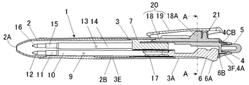
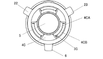
図1〜図8に示す実施形態1の出没筆記具1は、前軸2の雄ネジ部2Bと後軸3の雌ネジ部3Eを螺合により取り付けられる軸筒本体内に複数本(3本)の筆記体が前後方向に移動可能に収容されている。筆記体9の後部には、筆記体9のインキ収容筒10に収容した筆記具用インキと同色の操作体6を配設してあり、筆記体9は、コイルスプリング17により後方に付勢してあり、他の筆記体13は、筆記体9と同様にして、筆記体13の後部には、筆記体13のインキ収容筒14に収容した筆記具用インキと同色の操作体22を配設してある。操作体23を配設したもう一方の筆記体は、詳細は図示していないが、3本の筆記体を配設した従来から知られているスライド式の出没機構を具備する多芯の出没式筆記具である。
1 to 8, the
実施形態の筆記体9は、インキ収容筒10の先端部に、φ0.5mmのボールを回転自在に抱持したボールペンチップからなる筆記部12を、チップホルダー11を介して装着してある。また、インキ収容筒10内には、平均粒径が5μmの可逆熱変色性のマイクロカプセル顔料を含有し、EM型回転粘度計における1rpmでのインキ粘度が1020mPa・s(25℃)、100rpmでのインキ粘度が84mPa・s(25℃)で、剪断減粘指数が0.48の筆記具用水性インキと、このインキの後端に、グリース状のインキ追従体(図示せず)を直に収容してある。尚、インキ粘度は、EM型回転粘度計における100rpm、20℃において、40〜200mPa・sとすることが好ましい。
In the
後軸3の後部には、前後方向に延びる細長状の摺動溝3A、3B、3Cが3本、形成してあり、互いに、120度間隔に形成される。また、摺動溝3A、3B、3Cは、後方が開口していて、後軸3の後端で連通する開口部3AA、3BA、3CAを有している。後軸3の後端部は略円筒状であって、後軸3の外面には予めフィルム転写を施してある。
Three elongated
後軸3内には、略円筒状のスプリング支持部7を固着している。スプリング支持部7は、筆記体9、13等、3本の筆記体が挿通される内孔が軸方向に貫設し、スプリング支持部7と、各々の操作体6間には、コイルスプリング17が配置し、筆記体9及び摺動体6を後方に付勢してある。尚、図示はしていないが、他の操作体22、23も操作体6と同様に、スプリング支持部7と、各々の操作体間には、コイルスプリングが配置し、筆記体及び摺動体を後方に付勢してある。
A substantially cylindrical
また、後軸3の後部、且つ後軸3の摺動溝3B、3C間には、長手方向に沿って延びる凹状の装着部3Dを形成してあり、この装着部3Dにクリップ20を付設してある。装着部3Dは、後軸3の後端に開口部3DAを有していて、開口部3DAと装着部3Dとが連通している。この装着部3Dに、クリップ20のクリップ片19を装着するクリップ台18を挿入し、後軸3の後方側から前軸2側に押し込むことで、クリップ台18に設けた突起が、装着部3Dに設けた突起との乗り越し嵌合によって、後軸3にクリップ台18を着脱自在に付設してある。
A concave mounting
また、後軸3の後部には、雄ネジ部3Fを設けてあり、この雄ネジ部3Fに、頭冠4の雌ネジ部4Aをネジ嵌合によって着脱自在に装着してある。頭冠4を後軸3に装着すると、後軸3の後端に設けた突部3Gが、頭冠4の後端部に設けた貫通孔4CBとが凹凸嵌合して、頭冠4と後軸3とのネジ嵌合の緩みを抑制してある。この頭冠4を取り外すことで、後軸3の後端を露出することができ、筆記具全長Lから筆記具全長Mに短くすることができる。
Further, a
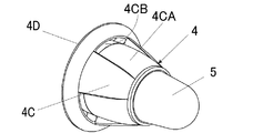
頭冠4は、後軸3の後部に当接する後端面4Dと、頭冠4の先端から後端面側に向かって拡径して延びる傾斜状の側壁4Cとを具備している。この側壁4Cの外面に長手方向に延びる凹溝4CAを、周方向の異なる位置に3個設けてあり、頭冠4を後軸3にネジ嵌合する時に、指が凹溝4CAに引っ掛かり、ネジ嵌合し易くしてある。また、凹溝4CAは、頭冠4の後端部に形成した貫通孔4CBに連通してある。このように、頭冠4の壁部4Cが先端に向かって縮径する傾斜状とすること、及び頭冠4の壁部4Cに凹溝4CAを設けることで、弾性部5の使用時に、筆跡が視認し易くなるので好ましい。また、頭冠4の後端部に貫通孔4CBを形成することで、強度の低下、及び後端面4Dの面積の減少を抑制するので好ましい。
The
さらにまた、頭冠4には、ゴム状弾性を有する弾性部5を具備している。具体的には、頭冠4に設けた嵌合突部4Bに、シリコーンゴムからなる弾性体(弾性部)5の突部5Aを落とし込み嵌合によって、容易に抜けないように装着してある。
Furthermore, the
筆記体8のボールペンチップからなる筆記部11を前軸2の先端開口部2Aから突出させるには、操作体6の操作部6Aを、摺動溝3Aに沿って、前軸2の先端開口部2A方向へスライドすることにより、操作体6に形成した係合突起6Bが後軸3内に形成した係止部(図示せず)に係止して、筆記体9の筆記部11を前軸の先端開口部2Aから選択して突出を維持して、筆記することができる。また、本実施形態においては、弾性部5を筆記面Tに圧接し、擦ることで発生する熱によって、筆跡を変色させることができる。このとき、クリップ片19の後端部と弾性部5との接線Sの角度αは、軸筒の軸線Jに対し40度であった。
In order to project the writing
また、筆記体8の筆記部11が前軸の先端開口部2Aから突出を維持した状態で、他の摺動体21の操作部21Aを前軸2の先端開口部2A方向にスライドすることで、摺動体20の解除突起が摺動体6の係止を解除し、コイルスプリング17により筆記体8の筆記部11を前軸2内に没入させることができる。
Further, by sliding the operation portion 21A of the other sliding
クリップ20は、クリップ片19を、クリップ台18の外壁に設けられた支柱18に連結し、クリップ片19の内壁とクリップ台18との間であって支柱18Aの後方に配設されるコイルスプリング21によって、クリップ片19の先端部の内壁を常時、クリップ台18の外壁の外面に弾性的に反発させるとともに、クリップ片19の後端部をクリップ台18側へ押圧することにより連結部を支点としクリップ台18に対しクリップ片19の先端部の内壁をクリップ台18から離間可能に配設してある。
The
頭冠4が後軸3の後端を閉鎖した状態から、後軸3と頭冠4のネジ嵌合3C、4Aを外し、後軸3の後端を露出させる。装着部3Dは、後軸3の後端に開口部3DAを有していて、開口部3DAと装着部3Dとが連通しているので、この状態であればクリップ20を取り出すことができる。
From the state in which the
本実施形態では、便宜上、ボールペンを3本配設してあるが、筆記体には、例えば、ボールペン、マーキングペン、シャープペンシル等が挙げられる。また、筆記体の本数は、1本、2本以上等、特に限定されるものではない。 In this embodiment, for convenience, three ballpoint pens are provided, but examples of the cursive include a ballpoint pen, a marking pen, and a mechanical pencil. The number of cursive letters is not particularly limited, such as one, two or more.
また、クリップの形状も特に限定されないが、クリップが、クリップ片とクリップ台とからなり、クリップ台の先端部に、前記クリップ片に向かって突出する係止部を形成し、該係止部が、軸筒表面から突出することで、クリップ片とクリップ台との挟持力を高めることができるので好ましい。さらにまた、クリップが、クリップ片とクリップ台との間に配設したコイルスプリングによって、クリップ片の先端部を常時、クリップ台の外面に弾性的に圧接するとともに、クリップ片の後端部をクリップ台側へ押圧することにより、クリップ片とクリップ台との連結部を支点としクリップ台に対しクリップ片の内壁の先端部を軸筒から離間可能に配設してあるため、クリップ片とクリップ台との挟持力を高めることができ、クリップを取り外して使用することもできるので好ましい。 In addition, the shape of the clip is not particularly limited, but the clip is composed of a clip piece and a clip base, and a locking portion that protrudes toward the clip piece is formed at the tip of the clip base, and the locking portion is By projecting from the surface of the shaft tube, the clamping force between the clip piece and the clip base can be increased, which is preferable. Furthermore, the clip always elastically presses the front end of the clip piece against the outer surface of the clip stand and the clip end clip portion is clipped by a coil spring disposed between the clip piece and the clip stand. Since the tip of the inner wall of the clip piece can be separated from the shaft cylinder with respect to the clip stand by using the connecting part between the clip piece and the clip stand as a fulcrum by pressing to the stand side, the clip piece and the clip stand This is preferable because the clip can be removed and used.
さらにまた、頭冠の側壁の外面に設ける凹溝の数や大きさも特に限定されるものではなく、側壁の外面の一部又は全面に長手方向に延びる凹溝を複数個、設けてあればよい。 Furthermore, the number and size of the concave grooves provided on the outer surface of the side wall of the crown are not particularly limited, and a plurality of concave grooves extending in the longitudinal direction may be provided on a part or the whole of the outer surface of the side wall. .
また、筆記具用インキも特に限定されるものではないが、粒子の平均の大きさが、体積基準で0.1〜30μmの顔料を含有し、前記ボールの縦方向のクリアランスが、30〜80μm、100m当たりのインキ消費量が、200〜800mgとすることで、濃く良好な筆跡及び良好な筆感を得ることができる。これは、ボールの縦方向のクリアランスが30μm未満では、粒子の平均の大きさが0.1〜30μmの顔料を有する筆記具用水性インキにおいて、100m当たりのインキ消費量が200〜800mgのようなインキ消費量を多くすることが困難であるとともに、80μmを超えると、インキ消費量が多く、筆跡乾燥性が低下する恐れがあるため、30から80μmとすることが最も好ましいためである。 The ink for the writing instrument is not particularly limited, but the average particle size contains a pigment of 0.1 to 30 μm on a volume basis, and the vertical clearance of the ball is 30 to 80 μm, By setting the ink consumption per 100 m to 200 to 800 mg, a dark and good handwriting and a good writing feeling can be obtained. This is an ink whose ink consumption per 100 m is 200 to 800 mg in a water-based ink for writing instruments having a pigment with an average particle size of 0.1 to 30 μm when the longitudinal clearance of the ball is less than 30 μm. This is because it is difficult to increase the amount of consumption, and when it exceeds 80 μm, the amount of ink consumption is large and the handwriting drying property may be lowered, so that it is most preferably 30 to 80 μm.
本実施例では、便宜上、操作体をスライドして係止する出没式筆記具を例示しているが、クリップをスライドして回転カムを作動する回転カム機構や回転操作により、筆記部を軸筒前端開口部から出没させる機構等、ノック式、スライド式、回転式等、特に限定されるものではない。 In the present embodiment, for the sake of convenience, a retractable writing instrument that slides and locks the operating body is illustrated, but the writing portion is moved to the front end of the shaft cylinder by a rotating cam mechanism or a rotating operation that slides the clip to operate the rotating cam. There is no particular limitation such as a mechanism that moves in and out from the opening, such as a knock type, a slide type, and a rotary type.
本発明の多芯筆記具は、インキの種類に限定されることなく、多芯筆記具として広く実施可能である。 The multi-core writing instrument of the present invention is not limited to the type of ink, and can be widely implemented as a multi-core writing instrument.
1 出没式筆記具
2 前軸
2A 先端開口部
3 後軸
3A、3B、3C 摺動溝
3D 装着部
3DA 開口部
3F 雄ネジ部
3G 突部
4 頭冠
4A 雌ネジ部
4B 嵌合突部
4C 側壁
4CA 凹溝
4CB 貫通孔
4D 後端面
5 弾性部
6、22、23 摺動体
6A 操作部
7 スプリング支持部
9、13 筆記体
10、14 インキ収容筒
12、16 筆記部
17 コイルスプリング
18 クリップ台
19 クリップ片
20 クリップ
DESCRIPTION OF
Claims (4)
Priority Applications (1)
| Application Number | Priority Date | Filing Date | Title |
|---|---|---|---|
| JP2012055982A JP5932412B2 (en) | 2012-03-13 | 2012-03-13 | Intrusive writing instrument |
Applications Claiming Priority (1)
| Application Number | Priority Date | Filing Date | Title |
|---|---|---|---|
| JP2012055982A JP5932412B2 (en) | 2012-03-13 | 2012-03-13 | Intrusive writing instrument |
Publications (3)
| Publication Number | Publication Date |
|---|---|
| JP2013188922A JP2013188922A (en) | 2013-09-26 |
| JP2013188922A5 JP2013188922A5 (en) | 2015-04-09 |
| JP5932412B2 true JP5932412B2 (en) | 2016-06-08 |
Family
ID=49389705
Family Applications (1)
| Application Number | Title | Priority Date | Filing Date |
|---|---|---|---|
| JP2012055982A Active JP5932412B2 (en) | 2012-03-13 | 2012-03-13 | Intrusive writing instrument |
Country Status (1)
| Country | Link |
|---|---|
| JP (1) | JP5932412B2 (en) |
Cited By (1)
| Publication number | Priority date | Publication date | Assignee | Title |
|---|---|---|---|---|
| DE102022002185A1 (en) | 2022-06-15 | 2023-12-21 | Stabilo International Gmbh | PEN |
Families Citing this family (3)
| Publication number | Priority date | Publication date | Assignee | Title |
|---|---|---|---|---|
| CN204160938U (en) * | 2014-01-22 | 2015-02-18 | 汇美环球有限公司 | Marker |
| JP7303356B2 (en) | 2018-10-31 | 2023-07-04 | 株式会社パイロットコーポレーション | thermochromic writing instrument |
| EP4306331A1 (en) | 2021-03-09 | 2024-01-17 | Kabushiki Kaisha Pilot Corporation (also trading as Pilot Corporation) | Friction body unit and thermochromic writing instrument |
Family Cites Families (4)
| Publication number | Priority date | Publication date | Assignee | Title |
|---|---|---|---|---|
| JPS54164640U (en) * | 1978-05-11 | 1979-11-19 | ||
| JP2005178828A (en) * | 2003-12-18 | 2005-07-07 | Tenryu Kagaku Kogyo Kk | Screw lid and pilfer-proof cap |
| JP4689378B2 (en) * | 2005-07-08 | 2011-05-25 | パイロットインキ株式会社 | Multi-core writing instrument |
| JP5706107B2 (en) * | 2010-02-03 | 2015-04-22 | パイロットインキ株式会社 | Thermochromic writing instrument |
-
2012
- 2012-03-13 JP JP2012055982A patent/JP5932412B2/en active Active
Cited By (1)
| Publication number | Priority date | Publication date | Assignee | Title |
|---|---|---|---|---|
| DE102022002185A1 (en) | 2022-06-15 | 2023-12-21 | Stabilo International Gmbh | PEN |
Also Published As
| Publication number | Publication date |
|---|---|
| JP2013188922A (en) | 2013-09-26 |
Similar Documents
| Publication | Publication Date | Title |
|---|---|---|
| JP5932412B2 (en) | Intrusive writing instrument | |
| JP6192964B2 (en) | Thermochromic writing instrument | |
| JP6338365B2 (en) | Thermochromic writing instrument and friction tool | |
| JP5358398B2 (en) | Thermochromic writing instrument | |
| JP2014124899A (en) | Thermochromic writing utensil | |
| JP6845741B2 (en) | Thermal discoloration writing tool | |
| JP6204662B2 (en) | Thermochromic writing instrument | |
| JP6204663B2 (en) | Thermochromic writing instrument | |
| JP2014124900A (en) | Thermochromic writing utensil | |
| JP5908234B2 (en) | Sliding multi-core writing instrument | |
| JP2016203596A (en) | Writing instrument with erasing member | |
| JP2012218389A (en) | Thermochromic writing utensil | |
| JP5908233B2 (en) | Multi-core writing instrument | |
| JP6275762B2 (en) | Multi-core writing instrument | |
| JP6410901B2 (en) | Thermochromic writing instrument | |
| JP6472240B2 (en) | Thermochromic writing instrument | |
| JP6315772B2 (en) | Writing instrument shaft | |
| JP6312382B2 (en) | Rotating payout writing instrument | |
| JP7118192B2 (en) | thermochromic writing instrument | |
| JP6472239B2 (en) | Thermochromic writing instrument | |
| JP6007235B2 (en) | Intrusive writing instrument | |
| JP3189357U (en) | Electrostatic input pen | |
| JP2016020056A (en) | Writing instrument | |
| JP6346009B2 (en) | Writing instrument | |
| JP6327786B2 (en) | Thermochromic writing instrument |
Legal Events
| Date | Code | Title | Description |
|---|---|---|---|
| A521 | Written amendment |
Free format text: JAPANESE INTERMEDIATE CODE: A523 Effective date: 20150223 |
|
| A621 | Written request for application examination |
Free format text: JAPANESE INTERMEDIATE CODE: A621 Effective date: 20150225 |
|
| A131 | Notification of reasons for refusal |
Free format text: JAPANESE INTERMEDIATE CODE: A131 Effective date: 20160209 |
|
| A521 | Written amendment |
Free format text: JAPANESE INTERMEDIATE CODE: A523 Effective date: 20160406 |
|
| TRDD | Decision of grant or rejection written | ||
| A01 | Written decision to grant a patent or to grant a registration (utility model) |
Free format text: JAPANESE INTERMEDIATE CODE: A01 Effective date: 20160426 |
|
| A61 | First payment of annual fees (during grant procedure) |
Free format text: JAPANESE INTERMEDIATE CODE: A61 Effective date: 20160428 |
|
| R151 | Written notification of patent or utility model registration |
Ref document number: 5932412 Country of ref document: JP Free format text: JAPANESE INTERMEDIATE CODE: R151 |