JP5927351B2 - Skin treatment equipment - Google Patents
Skin treatment equipment Download PDFInfo
- Publication number
- JP5927351B2 JP5927351B2 JP2015535133A JP2015535133A JP5927351B2 JP 5927351 B2 JP5927351 B2 JP 5927351B2 JP 2015535133 A JP2015535133 A JP 2015535133A JP 2015535133 A JP2015535133 A JP 2015535133A JP 5927351 B2 JP5927351 B2 JP 5927351B2
- Authority
- JP
- Japan
- Prior art keywords
- wheel
- skin
- angular position
- skin treatment
- facets
- Prior art date
- Legal status (The legal status is an assumption and is not a legal conclusion. Google has not performed a legal analysis and makes no representation as to the accuracy of the status listed.)
- Expired - Fee Related
Links
- 238000011282 treatment Methods 0.000 title claims description 53
- 238000011269 treatment regimen Methods 0.000 claims description 27
- 230000003287 optical effect Effects 0.000 claims description 7
- 230000037303 wrinkles Effects 0.000 claims description 7
- 230000037380 skin damage Effects 0.000 claims description 3
- 238000002834 transmittance Methods 0.000 claims 2
- 230000002547 anomalous effect Effects 0.000 description 5
- 238000010304 firing Methods 0.000 description 5
- 238000001514 detection method Methods 0.000 description 3
- 238000010586 diagram Methods 0.000 description 3
- 238000000034 method Methods 0.000 description 3
- 230000000694 effects Effects 0.000 description 2
- 238000011084 recovery Methods 0.000 description 2
- 230000037075 skin appearance Effects 0.000 description 2
- 230000002159 abnormal effect Effects 0.000 description 1
- 230000005540 biological transmission Effects 0.000 description 1
- 230000021615 conjugation Effects 0.000 description 1
- 230000001419 dependent effect Effects 0.000 description 1
- 238000006073 displacement reaction Methods 0.000 description 1
- 230000036555 skin type Effects 0.000 description 1
- 230000001225 therapeutic effect Effects 0.000 description 1
Images


Classifications
-
- A—HUMAN NECESSITIES
- A61—MEDICAL OR VETERINARY SCIENCE; HYGIENE
- A61B—DIAGNOSIS; SURGERY; IDENTIFICATION
- A61B18/00—Surgical instruments, devices or methods for transferring non-mechanical forms of energy to or from the body
- A61B18/18—Surgical instruments, devices or methods for transferring non-mechanical forms of energy to or from the body by applying electromagnetic radiation, e.g. microwaves
- A61B18/20—Surgical instruments, devices or methods for transferring non-mechanical forms of energy to or from the body by applying electromagnetic radiation, e.g. microwaves using laser
- A61B18/203—Surgical instruments, devices or methods for transferring non-mechanical forms of energy to or from the body by applying electromagnetic radiation, e.g. microwaves using laser applying laser energy to the outside of the body
-
- G—PHYSICS
- G02—OPTICS
- G02B—OPTICAL ELEMENTS, SYSTEMS OR APPARATUS
- G02B26/00—Optical devices or arrangements for the control of light using movable or deformable optical elements
- G02B26/08—Optical devices or arrangements for the control of light using movable or deformable optical elements for controlling the direction of light
- G02B26/10—Scanning systems
- G02B26/12—Scanning systems using multifaceted mirrors
-
- A—HUMAN NECESSITIES
- A61—MEDICAL OR VETERINARY SCIENCE; HYGIENE
- A61B—DIAGNOSIS; SURGERY; IDENTIFICATION
- A61B18/00—Surgical instruments, devices or methods for transferring non-mechanical forms of energy to or from the body
- A61B2018/00315—Surgical instruments, devices or methods for transferring non-mechanical forms of energy to or from the body for treatment of particular body parts
- A61B2018/00452—Skin
- A61B2018/0047—Upper parts of the skin, e.g. skin peeling or treatment of wrinkles
-
- A—HUMAN NECESSITIES
- A61—MEDICAL OR VETERINARY SCIENCE; HYGIENE
- A61B—DIAGNOSIS; SURGERY; IDENTIFICATION
- A61B18/00—Surgical instruments, devices or methods for transferring non-mechanical forms of energy to or from the body
- A61B2018/00636—Sensing and controlling the application of energy
- A61B2018/00773—Sensed parameters
- A61B2018/00779—Power or energy
-
- A—HUMAN NECESSITIES
- A61—MEDICAL OR VETERINARY SCIENCE; HYGIENE
- A61B—DIAGNOSIS; SURGERY; IDENTIFICATION
- A61B18/00—Surgical instruments, devices or methods for transferring non-mechanical forms of energy to or from the body
- A61B18/18—Surgical instruments, devices or methods for transferring non-mechanical forms of energy to or from the body by applying electromagnetic radiation, e.g. microwaves
- A61B18/20—Surgical instruments, devices or methods for transferring non-mechanical forms of energy to or from the body by applying electromagnetic radiation, e.g. microwaves using laser
- A61B2018/2035—Beam shaping or redirecting; Optical components therefor
- A61B2018/20351—Scanning mechanisms
- A61B2018/20355—Special scanning path or conditions, e.g. spiral, raster or providing spot overlap
-
- A—HUMAN NECESSITIES
- A61—MEDICAL OR VETERINARY SCIENCE; HYGIENE
- A61B—DIAGNOSIS; SURGERY; IDENTIFICATION
- A61B18/00—Surgical instruments, devices or methods for transferring non-mechanical forms of energy to or from the body
- A61B18/18—Surgical instruments, devices or methods for transferring non-mechanical forms of energy to or from the body by applying electromagnetic radiation, e.g. microwaves
- A61B18/20—Surgical instruments, devices or methods for transferring non-mechanical forms of energy to or from the body by applying electromagnetic radiation, e.g. microwaves using laser
- A61B2018/2035—Beam shaping or redirecting; Optical components therefor
- A61B2018/205547—Controller with specific architecture or programmatic algorithm for directing scan path, spot size or shape, or spot intensity, fluence or irradiance
Landscapes
- Physics & Mathematics (AREA)
- Health & Medical Sciences (AREA)
- Optics & Photonics (AREA)
- Surgery (AREA)
- Life Sciences & Earth Sciences (AREA)
- Heart & Thoracic Surgery (AREA)
- Molecular Biology (AREA)
- Nuclear Medicine, Radiotherapy & Molecular Imaging (AREA)
- Engineering & Computer Science (AREA)
- Biomedical Technology (AREA)
- Electromagnetism (AREA)
- Medical Informatics (AREA)
- Otolaryngology (AREA)
- Animal Behavior & Ethology (AREA)
- General Health & Medical Sciences (AREA)
- Public Health (AREA)
- Veterinary Medicine (AREA)
- General Physics & Mathematics (AREA)
- Radiation-Therapy Devices (AREA)
- Measuring And Recording Apparatus For Diagnosis (AREA)
- Laser Surgery Devices (AREA)
Description
この発明は皮膚治療装置に関し、皮膚治療装置は、皮膚を光学的に治療するための光ビームを提供するための光源と、光ビームを皮膚に向かって反射させるためのホイール表面を備えるホイールと、ホイールの角位置を変更するためにホイールを回転させるための駆動手段と、光源を制御するための制御回路とを含み、ホイールの異なる角位置は、光ビームのための反射のそれぞれの方向に対応する。 The present invention relates to a skin treatment device, the skin treatment device comprising a light source for providing a light beam for optically treating the skin, a wheel comprising a wheel surface for reflecting the light beam toward the skin, Includes driving means for rotating the wheel to change the angular position of the wheel and a control circuit for controlling the light source, the different angular position of the wheel corresponding to the respective direction of reflection for the light beam To do.
そのような皮膚治療装置は、例えば、US2012/0197357A1として公開されている米国特許出願中に開示されている。前記皮膚治療装置は、レーザ源と、影響を受けていない皮膚組織によって取り囲まれた熱的に変性させられた皮膚組織の顕微鏡治療ゾーン(MTZ)を創り出すための光学パターン生成器とを含む。この治療は皮膚回復機構を増強し、皮膚外観を向上させる。複数のアキシコンセグメントを備えるアキシコンホイールが、レーザビームを皮膚表面上の対応する複数の異なる場所に向かって反射させる。制御回路がレーザ源を制御して個々のアキシコンセグメントを無作為に照らす。使用者が皮膚治療装置を皮膚表面に沿ってドラグする間に、MTZの無作為パターンが皮膚表面に適用される。使用者によって設定される強度レベルが無作為パターンの密度を決定する。 Such a skin treatment device is disclosed, for example, in a US patent application published as US2012 / 0197357A1. The skin treatment device includes a laser source and an optical pattern generator for creating a microscopic treatment zone (MTZ) of thermally denatured skin tissue surrounded by unaffected skin tissue. This treatment enhances the skin recovery mechanism and improves the skin appearance. An axicon wheel comprising a plurality of axicon segments reflects the laser beam toward a corresponding plurality of different locations on the skin surface. A control circuit controls the laser source to randomly illuminate the individual axicon segments. A random pattern of MTZ is applied to the skin surface while the user drags the skin treatment device along the skin surface. The intensity level set by the user determines the density of the random pattern.
既知の装置では、あらゆるアキシコン小面がトリガー薄片を有し、トリガ薄片は、アキシコンホイールの回転中に薄片検出器を通過後、薄片検出器によって検出される。薄片検出器は制御回路に結合され、制御回路は薄片検出器信号に基づきアキシコンホイールの回転速度を決定する。アキシコンホイールの回転速度及び使用者が皮膚表面に沿って装置をドラグする測定速度に基づき、制御回路は多かれ少なかれ一定の密度で無作為に分散させられるMTZを提供し得る。 In known devices, every axicon facet has a trigger flake that is detected by the flake detector after passing through the flake detector during rotation of the axicon wheel. The flake detector is coupled to a control circuit, which determines the rotational speed of the axicon wheel based on the flake detector signal. Based on the rotational speed of the axicon wheel and the measured speed at which the user drags the device along the skin surface, the control circuit may provide an MTZ that is randomly distributed at a more or less constant density.
強度レベルを設定する可能性は、装置の作動に対する多少の制御をもたらすが、皮膚種類、皮膚状況、皮膚治療及び使用者の好みの違いにより十分に適合するよう、治療制御を向上させる必要が依然としてある。例えば、装置の作動を、皺、細線又はシミのような、特定の皮膚特徴に対して特異的にすることが望ましくあり得る。 The possibility to set the intensity level provides some control over the operation of the device, but there is still a need to improve treatment control to better suit the differences in skin type, skin condition, skin treatment and user preferences. is there. For example, it may be desirable to make the operation of the device specific to a particular skin feature, such as wrinkles, fine lines or spots.
提供される皮膚治療に対する制御の改良を有する、冒頭段落において述べた種類の皮膚治療装置を提供することが、本発明の目的である。 It is an object of the present invention to provide a skin treatment device of the kind mentioned in the opening paragraph with improved control over the provided skin treatment.
本発明の第1の特徴によれば、この目的は、皮膚を光学的に治療するための光ビームを提供するための光源と、光ビームを皮膚に向かって反射させるためのホイール表面を備えるホイールと、ホイールの角位置を変更するためにホイールを回転させるための駆動手段であって、ホイールの異なる角位置は、光ビームのためのそれぞれの異なる反射方向に対応する駆動手段と、ホイールの角位置又は角位置と対応するパラメータを検出するための角位置検出器と、所定の皮膚治療パターン、及びホイールの異なる角位置又は角位置に対応するパラメータと光ビームについての対応するそれぞれの異なる反射方向又は反射方向に対応するパラメータとの間の関係を記憶するための記憶手段と、光源、角位置検出器及び記憶手段に結合される制御回路とを含み、制御回路は、ホイールの各回転のために、光ビームがホイールの選択的な角位置においてのみホイール表面を照らして所定の皮膚治療パターンを実現するような方法において、角位置検出器によって検出される角位置に依存して光源を制御するよう動作する、皮膚治療装置、を提供することによって達成される。 According to a first aspect of the invention, this object is achieved by a wheel comprising a light source for providing a light beam for optically treating the skin and a wheel surface for reflecting the light beam towards the skin. Driving means for rotating the wheel to change the angular position of the wheel, wherein the different angular positions of the wheel correspond to respective different reflection directions for the light beam; Angular position detector for detecting the position or parameters corresponding to the angular position, a predetermined skin treatment pattern, and different angular positions of the wheel or parameters corresponding to different angular positions and corresponding different reflection directions for the light beam Or a storage means for storing the relationship between the parameters corresponding to the reflection direction and a control circuit coupled to the light source, the angular position detector and the storage means. And for each rotation of the wheel, the control circuit provides an angular position detector in such a way that the light beam illuminates the wheel surface only at a selective angular position of the wheel to achieve a predetermined skin treatment pattern. This is achieved by providing a skin treatment device that operates to control the light source in dependence on the angular position detected by.
US2012/0197357A1の皮膚治療装置において、治療は無作為且つ未知の位置にあるアキシコンホイールから常に始まる。次に、光源はアキシコンホイールの未知の小面を無作為に照らし、その結果、皮膚上の無作為な位置にあるMTZをもたらす。既知の装置のために、これは実際には問題とみなされない。何故ならば、ホイールのあらゆる回転のために、全ての小面が照らされる機会は均等であり、全体的な結果は所望の密度を備えたMTZの均質な分散である。 In the skin treatment device of US2012 / 0197357A1, treatment always starts with an axicon wheel in a random and unknown position. The light source then randomly illuminates the unknown facets of the axicon wheel, resulting in MTZs at random locations on the skin. For known devices, this is not really considered a problem. Because, for every rotation of the wheel, the chances that all facets are illuminated are equal and the overall result is a homogeneous distribution of MTZ with the desired density.
本発明に従った装置を用いるならば、ホイールの選択的な角位置及び光ビームの対応する反射方向で治療を開始することが可能であるか、或いは、一般的には、所定の皮膚治療パターンに対応する反射方向の選択的な順序において光ビームを連続的に反射させることによって皮膚上の所定のパターンに従ってMTZをもたらすことが可能である。ホイールの異なる角位置に対応する反射方向は固定されるので、角位置検出器を用いて得られるホイールの角位置の知識は、光源からの光が反射される方向に瞬間的に知ることを可能にする。例えば、制御回路は光源を制御してホイールの角回転の各第1又は第2の半分の間だけホイール表面を照らす。角位置の知識を記憶させられる対応する反射方向と組み合わせることは、制御回路が、例えば、使用者によって選択され得る、所定の皮膚治療パターンに従った皮膚上の選択的な位置でのみMTZを創り出すことを可能にする。装置を皮膚に沿ってドラグしながら、皮膚上の事前に選択される場所にMTZを備える皮膚治療パターンが、既知の装置によって生成される無作為パターンの代わりに現れる。皮膚治療パターンは、例えば、MTZの直線的な垂直線、水平線又は対角線を含み得る。MTZの揺動パターン又は異なる形状のMTZの別個の地点も生成し得る。 With the device according to the invention, it is possible to start treatment at the selective angular position of the wheel and the corresponding reflection direction of the light beam or, in general, a predetermined skin treatment pattern It is possible to produce MTZ according to a predetermined pattern on the skin by continuously reflecting the light beam in a selective sequence of reflection directions corresponding to. Since the reflection direction corresponding to the different angular position of the wheel is fixed, knowledge of the angular position of the wheel obtained using the angular position detector can be instantaneously known in the direction in which the light from the light source is reflected To. For example, the control circuit controls the light source to illuminate the wheel surface only during each first or second half of the angular rotation of the wheel. Combining the knowledge of the angular position with the corresponding reflection direction stored, the control circuit creates the MTZ only at selective positions on the skin according to a predetermined skin treatment pattern, which can be selected, for example, by the user. Make it possible. While dragging the device along the skin, a skin treatment pattern with MTZ in a preselected location on the skin appears instead of the random pattern generated by known devices. The skin treatment pattern may include, for example, a linear vertical line, horizontal line or diagonal line of the MTZ. MTZ rocking patterns or distinct points of differently shaped MTZ may also be generated.
好適実施態様において、角位置検出器は、ホイールの異なる角位置のうちの所定の角位置と関連付けられる識別要素の通過を検出するように配置される。識別要素は、ホイール表面自体の特性又は特定の位置でホイール表面に取り付けられる要素であってよく、或いは単に何らかの所定の角位置でホイール上に或いはホイールに設けられる要素であってもよい。もちろん、第1の識別要素に加えて、第2の識別要素の通過も検出可能であり、或いはより一層特異な識別要素の通過さえも検出可能であり、各特異な識別要素は異なる角位置に対応する。しかしながら、一般的には、本発明をホイールの角位置を検出するための如何なる種類の角位置検出器と共に或いは前記角位置と対応するパラメータを検出する如何なる種類の検出器と共に用い得る。 In a preferred embodiment, the angular position detector is arranged to detect the passage of an identification element associated with a predetermined angular position among the different angular positions of the wheel. The identification element may be a characteristic of the wheel surface itself or an element that is attached to the wheel surface at a specific position, or may simply be an element that is provided on or on the wheel at some predetermined angular position. Of course, in addition to the first discriminating element, the passage of the second discriminating element can also be detected, or even the passage of even more specific discriminating elements, each unique discriminating element being at a different angular position. Correspond. However, in general, the invention can be used with any kind of angular position detector for detecting the angular position of the wheel or with any kind of detector for detecting a parameter corresponding to said angular position.
好適実施態様において、ホイール表面は、光ビームを相互に異なる反射方向において皮膚に向かって反射させるための多数の小面を含み、各小面は、異なる反射方向のうちの1つに対応する。更なる実施態様において、識別要素は多数の小面のうちの所定の単一の小面と関連付けられる。適切なホイールの実施例はアキシコンホイールである。しかしながら、本発明は小面付きホイール又はアキシコンホイールの使用に全く限定されないことが留意されるべきである。例えば、その反射方向がその円周方向において漸進的に変化するホイールを同様に用いてもよく、類似の有利な効果を伴う。実際には、小面の数を更に増大させ且つ後続の小面の間の向きの違いを減少させることによって、円周方向に漸進的に且つ連続的に変化する反射方向を備えるそのようなホイールの近似が得られる。 In a preferred embodiment, the wheel surface includes a number of facets for reflecting the light beam towards the skin in mutually different reflection directions, each facet corresponding to one of the different reflection directions. In a further embodiment, the identification element is associated with a predetermined single facet of a number of facets. An example of a suitable wheel is an axicon wheel. However, it should be noted that the present invention is in no way limited to the use of faceted or axicon wheels. For example, a wheel whose reflection direction gradually changes in its circumferential direction may be used as well, with similar advantageous effects. In practice, such a wheel with a reflective direction that gradually and continuously changes in the circumferential direction by further increasing the number of facets and reducing the difference in orientation between subsequent facets. An approximation of is obtained.
本発明によれば、記憶手段は、ホイールの異なる角位置と、光ビームについての対応するそれぞれの異なる反射方向又は反射方向に対応するパラメータとの間の関係を記憶するよう動作する。角位置の代わりに、記憶手段は前記角位置と対応する如何なるパラメータをも用い得る。反射方向の代わりに、記憶手段は前記反射方向と対応する如何なるパラメータをも用い得る。例示的な実施態様において、記憶手段は、多数の小面の順序を記憶するように動作し、制御回路は、記憶させられる多数の小面の順序及び多数の小面のうちの所定の単一の小面の通過に基づき、小面を選択的に照らすように配置される。この実施態様において、反射方向と対応するパラメータは小面の連番であり、角位置は多数の小面のうちの所定の単一の小面の通過及びホイールの回転速度に基づき監視される。 According to the invention, the storage means is operative to store the relationship between the different angular positions of the wheel and the corresponding different reflection directions or parameters corresponding to the reflection directions for the light beam. Instead of the angular position, the storage means can use any parameter corresponding to the angular position. Instead of the reflection direction, the storage means can use any parameter corresponding to the reflection direction. In an exemplary embodiment, the storage means operates to store the order of multiple facets, and the control circuit is configured to store the order of multiple facets stored and a predetermined single of the multiple facets. Is arranged to selectively illuminate the facets based on the passage of the facets. In this embodiment, the parameter corresponding to the direction of reflection is the facet serial number, and the angular position is monitored based on the passage of a given single facet of the many facets and the rotational speed of the wheel.
任意的に、装置は皮膚の特性的特徴を検出するための皮膚特徴検出器を更に含み、皮膚特徴検出器は、制御回路に結合させられ、制御回路は、検出される特性的特徴に基づき、所定の皮膚治療パターンを定めるように配置される。検出される皮膚特徴は、例えば、皺、シミ又は皮膚損傷であり得る。その場合には、適用される治療パターンは、例えば、皺に追従し、或いは周囲の皮膚領域を同様に治療せずにシミを治療する。皮膚特徴及び皮膚特性を検出するための例示的な検出器は、例えば、米国特許出願公開US2006/0239547A1中に記載されている。 Optionally, the apparatus further includes a skin feature detector for detecting a characteristic feature of the skin, the skin feature detector coupled to the control circuit, the control circuit based on the detected characteristic feature, Arranged to define a predetermined skin treatment pattern. The detected skin feature can be, for example, wrinkles, spots or skin damage. In that case, the applied treatment pattern follows for example wrinkles, or treats spots without treating the surrounding skin area as well. An exemplary detector for detecting skin features and skin characteristics is described, for example, in US Patent Application Publication US2006 / 0239547A1.
多数の小面のうちの所定の単一の小面の通過の検出を多くの異なる方法において行い得る。特定の小面を認識する2つの異なる方法を組み合わせることによって、前記通過の検出の確実性を向上させ得る。例えば、多数の小面のうちの所定の単一の小面は、他の小面の透光率(translucency coefficient)と異なる透光率を有し得る。角位置検出器は、多数の小面のうちの所定の単一の小面を通過した光ビームの一部を検出するための光センサを含み得る。 Detection of the passage of a given single facet out of a number of facets can be done in many different ways. By combining two different methods of recognizing a particular facet, the certainty of the detection of the passage can be improved. For example, a given single facet of a number of facets may have a light transmission that is different from the translucency coefficient of the other facets. The angular position detector may include an optical sensor for detecting a portion of the light beam that has passed through a predetermined single facet of a number of facets.
代替的に、各小面は薄片を含み得る。多数の小面のうちの所定の単一の小面の薄片は他の小面の薄片と幾何学的に異なり、角位置検出器は幾何学的に異なる薄片を検出するよう配置される。この実施態様では、多数の小面のうちの所定の単一の小面の通過を検出するために、光源を始動させるための規則的なトリガ信号も用い得る。多数の小面のうちの所定の単一の小面以外の全ての小面は、従来技術から知られるような同じトリガ信号をもたらし得る。多数の小面のうちの所定の単一の小面が通過する毎に、即ち、ホイールの一回転毎に、角位置検出器は、制御回路によって認識される別個の信号をもたらす。「幾何学的に異なる」は、例えば、幾何学的に異なる薄片が他の薄片よりも短いこと、或いは幾何学的に異なる薄片が間隙によって分離される2つの薄片部分を含むことを意味し得る。 Alternatively, each facet may include a flake. A given single facet flake of a number of facets is geometrically different from the other facet flakes, and the angular position detector is arranged to detect a geometrically different flake. In this embodiment, a regular trigger signal for starting the light source may also be used to detect the passage of a predetermined single facet of a number of facets. All facets of a number of facets other than a given single facet can result in the same trigger signal as known from the prior art. Each time a predetermined single facet of a number of facets passes, i.e. every revolution of the wheel, the angular position detector provides a separate signal that is recognized by the control circuit. “Geometrically different” may mean, for example, that a geometrically different flake is shorter than the other flakes, or that a geometrically different flake includes two flake portions separated by a gap. .
代替的に、ホイール表面は、多数の小面のうちの所定の単一の小面と関連付けられる孔を含み得る。角位置検出器は、第2の光源と、光センサとを含み、第2の光源及び光センサは、第2の光源からの光が孔を通じて光センサに達し得るように配置される。同様に、ホイール表面に更なる反射表面を設け得る。更なるホイール表面は、多数の小面のうちの所定の単一の小面と関連付けられ、角位置検出器は、第2の光源と、光センサとを含み、第2の光源及び光センサは、第2の光源からの光が更なる反射表面を介して光センサに達し得るように配置される。 Alternatively, the wheel surface may include holes associated with a given single facet of a number of facets. The angular position detector includes a second light source and an optical sensor, and the second light source and the optical sensor are arranged so that light from the second light source can reach the optical sensor through the hole. Similarly, additional reflective surfaces can be provided on the wheel surface. The additional wheel surface is associated with a predetermined single facet of a number of facets, the angular position detector includes a second light source and a light sensor, wherein the second light source and light sensor are , Arranged such that light from the second light source can reach the photosensor via a further reflective surface.
本発明のこれらの及び他の特徴は、以下に記載する実施態様から明らかであり、以下に記載する実施態様を参照して解明されるであろう。 These and other features of the invention will be apparent from and will be elucidated with reference to the embodiments described hereinafter.
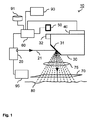
図1は、皮膚治療装置10を図式的に示している。皮膚治療装置10は、光ビーム21を提供するための光源、この場合には、レーザ源20を含む。複数のアキシコン小面31を備えるアキシコンホイール30が、光ビーム21を、対物レンズ75及び装置10の出口窓70を通じて、皮膚80に向かって反射させる。各アキシコン小面31は、光ビーム21のためのそれぞれの異なる方向の反射をもたらす。従って、アキシコンホイール30の回転中、光ビーム21は、皮膚80の対応する複数の異なる場所に向かって反射させられる。皮膚80で、光ビームは影響を受けていない組織によって取り囲まれた熱的に変性させられた皮膚組織の顕微鏡治療ゾーン(MTZ)を創り出す。この治療は皮膚回復機構を増強し、皮膚外観を向上させる。レーザ源20は制御回路60に結合され、制御回路60はレーザ源20を制御して、選択的な瞬間に個々のアキシコン小面31を照らす。アキシコンホイール30は、アキシコンホイール30の異なる小面31(ファセット)が入射する光ビーム21の経路を連続的に通るように、駆動手段40によって回転させられる。光ビーム21を異なる方向に反射させて、光を到達可能位置の範囲内の異なる位置で皮膚80に衝突させるために、アキシコンホイール30の異なるアキシコン小面31の反射表面領域は、異なる角度で方向付けられる。
FIG. 1 schematically shows a
アキシコンホイール30は、小面31の隣に設けられるトリガ薄片32(triggering flake)を更に含む。トリガ薄片32の通過は、薄片検出器50(flake detector)によって検出される。薄片検出器50は、制御回路60に結合される。薄片検出器50によって生成されるトリガ信号の周波数は、アキシコンホイール30の回転速度に依存する。トリガ信号に基づき、制御回路60は光源20を制御してアキシコンホイール30の各回転の所望の部分の間に光を放射させる。12個の小面31を備えるアキシコンホイール30の従来技術の実施例において、制御回路60は、例えば、1回の回転中に通過する小面31の2、4又は6個で、或いは12個でさえも、光パルスをもたらし得る。更に、装置10は、使用者が皮膚表面80に沿って装置10をドラグする手速度を決定するための手段90を含み得る。制御回路60は、手速度と無関係である多かれ少なかれ一定の密度でMTZをもたらすために、測定される手速度に依存する光源20の発火速度に適合させ得る。
The
本発明によれば、装置10の制御回路60は、光源20の発火速度をアキシコンホイール30の回転速度及び使用者の測定される手速度に適合させ得るのみならず、制御回路60は、所定の皮膚治療パターンのMTZを皮膚80にもたらすために光源20によって照らされるべき実際の小面31を選択するようにも配置される。以下、図5乃至9を参照して、これがどのように達成されるかを説明する。所望の皮膚治療パターンは、例えば、使用者によって選択され得る。
In accordance with the present invention, the
装置10は、例えば、皺、皮膚損傷、シミ又は他の皮膚特徴を検出するための、皮膚特徴検出器95を更に含み得る。皮膚特徴検出器95は、色又は皮膚水分のような皮膚特性を検出するよう動作可能であり得る。皮膚特徴検出器95は、例えば、皮膚80を観察するためのカメラや、皮膚表面80で反射した後の治療光ビーム21を検出し且つ分析するための検出器も含み得る。皮膚特徴検出器95は、治療を検出される特徴に適合させ得るように、制御回路60に結合される。例えば、治療が検出される皺又はシミだけに影響を与えるように、光源20を制御し得る。皮膚の選択的な部分が治療されないようにも、光源20を制御し得る。
The
図2は、図1の皮膚治療装置10のための従来技術のアキシコンホイール30の頂面図を示している。アキシコンホイール30は、光源20から来る光を方向変更し且つ反射するための12個の小面31(facet)を含む。トリガ薄片32が各小面31に伴う。トリガ薄片32の通過は、薄片検出器50によって検出される。光源20は薄片検出器50によって生成されるトリガ信号に依存して制御される。図3は、図1のアキシコンホイール30の断面図を示している。
FIG. 2 shows a top view of a prior
図4a、4b及び4cは、図2に従った従来技術のアキシコンホイール30が用いられるときに、図1の皮膚治療装置で得られ得る治療パターンの実施例を示している。皮膚80上のMTZ81のこれらの例示的なパターンは、装置10を皮膚表面80上でドラグしながら、制御された発火速度でアキシコンホイール30上の小面31を無作為に照らすことによって得られる。発火速度は、アキシコンホイールの観察される回転速度及び使用者の測定される手速度に依存して制御される。発火速度は、多かれ少なかれ一定の密度のMTZが手速度と無関係にもたらされるように制御される。例えば、使用者によって選択される強度レベルに依存して及び/又は1つ又はそれよりも多くの自動的に検出される皮膚特性に依存して、密度を選択し得る。これらの図面において、図4aは、高密度パターンの実施例を示しており、図4bは、中間密度パターンの実施例を示しており、図4cは、低密度パターンの実施例を示している。
4a, 4b and 4c show examples of treatment patterns that can be obtained with the skin treatment device of FIG. 1 when a prior
図5aには、薄片検出器50によって生成される結果として得られるトリガ信号132と共に、「通常の」トリガ薄片32が示されている。この実施例において、従来技術のアキシコンホイール30の全ての薄片32は、(少なくとも薄片検出器50によって観察される次元において)同じ形状を有する。トリガ信号32の周波数は、アキシコンホイール30の回転速度に依存する。トリガパルスの幅は、トリガ薄片32の幅に依存する。
In FIG. 5 a, a “normal”
図5b及び5cは、相互に異なるトリガ薄片33,34を備えるアキシコンホイール30を有する、本発明に従った装置10のための例示的なトリガ信号を示している。図5bでは、トリガ薄片33のうちの少なくとも1つが、他のものと異なって作製されている。この実施例において、薄片33は、1つの通常の薄片32を2つの部分に分割することによって異なって作製されており、それらの間には間隙がある。この異常型の薄片33が薄片検出器50を通る度に、トリガ信号133は、通常の薄片32が通るときのトリガ信号132と異なる。1つのトリガ信号の代わりに、異常型の薄片33は、2つの別個のより小さいパルスを引き起こす。この異常型の薄片33が検出されるとき、制御回路は、この異常型の薄片33と関連付けられる小面31が検出器を通過したことを知り、よって、アキシコンホイール30の正確な回転位置も知る。これは制御回路60がアキシコンホイール30の選択的な小面31のみが照明されるのを可能にすることを可能にする。
FIGS. 5 b and 5 c show exemplary trigger signals for the
図5cは、異常型の薄片34を提供する代替的な方法を示している。この薄片34は、通常の薄片32の半分の幅であり、その結果、トリガ信号134中のトリガパルスはより小さい。このより小さいパルスの検出は、異常型の薄片34と関連付けられる所定の小面34の通過を示す。
FIG. 5 c shows an alternative method of providing an
図6a、6b、6c、7a、7b及び7cは、本発明に従った皮膚治療装置によって得られる皮膚治療パターンの実施例を示している。皮膚80でのMTZ81のパターンは、1回に1つの走査線でアキシコンホイール30の小面31の一部又は全部を選択的に照らすことによってもたらされる。これらの図面中に(並びに図4a、4b及び4c中に)示されるパターンは、水平な走査線と走査線に対して垂直な方向において皮膚表面80上を移動する装置10とを示していることが、留意されなければならない。装置10が、異なる方向において、可能であれば直線でない方向において、皮膚表面に沿ってドラグされるとき、パターンは相応して斜めにされる。任意的に、照らされるべき小面31の選択は、装置の移動の方向に依存し得る。
Figures 6a, 6b, 6c, 7a, 7b and 7c show examples of skin treatment patterns obtained with a skin treatment device according to the invention. The pattern of
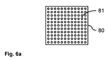
図6aには、あらゆる走査線でアキシコンホイール30の全ての小面31を照らすことによって得られるパターンが示されている。このパターンを得るために、装置10がアキシコンホイール30の正確な角位置を知り得べき必要はない。図6b及び6c(並びに7a、7b及び7c)のパターンのためには、例えば、多数の小面のうちの所定の単一の小面が装置10内の選択的な位置を通るときを決定することによって、アキシコンホイールの角位置を決定することが重要である。多数の小面のうちの所定の単一の小面の通過を検出するとき、異なる小面向きの正確な順序を決定し得る。それは皮膚80上に所望のMTZパターンを描くことを可能にする。しかしながら、アキシコンホイール30の実際の角位置を検出するために、装置は如何なる適切な角位置検出器をも用い得る。
FIG. 6a shows the pattern obtained by illuminating all
図6bは、小面31の2つだけで光ビームを反射させることによって得られるパターンを示している。これらの2つの小面をアキシコンホイール30上で互いに隣接して設けてもよいし、設けなくてもよい。これらの2つの小面31の向きは僅かに異なるだけであり、その結果、対応するMTZ81は互いに隣接して配置される。小さな垂直治療パターンが、装置10の皮膚特徴検出器によって検出される皺又は他の皮膚特徴に追従し得る。図6cは、走査線毎に4つの小面31が照らされることを要求するパターンを示している。図6b及び6cのパターンの両方のために、(走査線の向きと平行な方向における装置10のいずれの変位のために矯正は行われないと想定して)同じ小面31が走査線毎に照らされる。
FIG. 6 b shows the pattern obtained by reflecting the light beam with only two of the
例えば、単一の垂直線のパターンのために、制御回路60がアキシコンホイール30上の全ての小面31の正確な向き及び向きの順序を知る必要はない。その状況では、それは小面のうちの所定の単一の小面の通過を検出し且つアキシコンホイール30の回転毎に同じ小面を照らすのに十分である。
For example, for a single vertical line pattern, the
図7a、7b及び7cのパターンのために、各走査線で異なる小面31が選択される。これらのパターンを得るためには、全ての小面の位置及び向きの知識が必要とされる。記憶手段91が制御回路60に結合させられ、所定の皮膚治療パターン、及びアキシコンホイール30の異なる角位置と光ビーム21についての対応するそれぞれの異なる反射の方向との間の関係を記憶する。例えば、記憶手段91は、ファセット部材のリストと、アキシコンホイール30でのそれらの位置と、対応する反射の方向とを含む、データベースを記憶し得る。加えて、データベースはどのファセットがどの識別要素と関連付けられるかについての情報を記憶し得る。制御回路60は、アキシコンホイール30の各回転のために、光ビーム21が選択的な角位置又は小面でのみホイール表面を照明して所定の皮膚治療パターンを実現するような方法において、角位置検出器によって検出される角位置、この実施例では、識別要素の通過に依存して、光源20を制御するように動作する。図6b及び6cのパターンと同様に、図7a、7b及び7cのパターンは、特定の検出される皮膚特徴に追従してもよいし、或いは装置が皮膚表面80で偶然配置される位置で選択され且つ適用されてもよい。
図8は、本発明に従った皮膚治療装置における角位置検出器の幾つかの実施例を示している。第1に、異なる形状を備える薄片34を検出するために、既に上述した通常薄片検出器50を用い得る。薄片検出器50は、例えば、図5cを参照して同様に上記で議論した、より短い薄片34を検出し得てもよい。代替的に、アキシコンホイール30の回転毎に一度だけ通過するより長い薄片53を検出するために、第1の薄片検出器50に隣接して追加的な薄片検出器51を設け得る。追加的な薄片検出器51がより短い薄片以外の全ての薄片を検出するように、1つのより短い薄片を提供することによって類似の効果が得られる。その場合、所定の小面31は、第1の薄片検出器50がトリガパルスを提供する小面31である。
FIG. 8 shows several embodiments of the angular position detector in the skin treatment device according to the present invention. First, the
特定の小面31を検出する他の方法は、アキシコンホイール30の小面31の背後に光検出器52を配置し、小面のうちの所定の単一の小面を他の小面よりも僅かに多く又は僅かに少なく半透明にすることである。異なる小面が光検出器52を通過するとき、光検出器信号は異なる信号をもたらし、よって、それは小面のうちの所定の単一の小面の通過を示す。全ての小面が照明されるように光源20が制御されるならば、異なる小面を検出するためにも治療光ビーム21を用い得る。さもなければ、この目的のために、別個の追加的な光源を用いることが好ましくあり得る。
Another method for detecting a
更なる代替として、ホイール表面は、マーキングを認識し得る検出器(図示せず)によって検出される特殊なマーキング54を含み得る。例えば、マーキング54は、カメラによって検出される着色点、又は光エミッタ及び光検出器の組み合わせによって検出される反射地点である。マーキング54は、アキシコンホイール30の孔であってもよく、光エミッタ及び光検出器はホイール30の両側に設けられる。
As a further alternative, the wheel surface may include
図9は、本発明に従った皮膚治療装置における角位置検出器の更なる実施例を示している。この実施態様は異なる小面31の間の向きの違いを活用する。ここでは、追加的な光源22が設けられ、光検出器56は所定の小面31での反射後の追加的な光源22からの光を検出するためにある。異なる小面31は異なる方向において光を反射する。光検出器56の小面の小さなスリット55が、多数の小面のうちの所定の単一の小面によって精密に正しい角度で反射される光のみが光検出器56に到達することを保証する。小面のうちの所定の単一の小面以外の小面によって反射される光は、光検出器56に到達しない。よって、光検出器56は、多数の小面31のうちの所定の単一の小面が通過する度毎にトリガ信号をもたらす。
FIG. 9 shows a further embodiment of the angular position detector in the skin treatment device according to the invention. This embodiment takes advantage of the orientation differences between the
上述の実施態様は本発明を限定するというよりも本発明を例示すること並びに当業者は付属の請求項の範囲から逸脱せずに多くの代替的な実施態様を設計し得ることが留意されるべきである。請求項において括弧内に配置される如何なる参照記号も請求項を限定するものとして解釈されてはならない。「含む」という動詞及びその活用形の使用は請求項中に述べられる要素又はステップ以外の要素又はステップの存在を排除しない。ある要素に先行する不定冠詞はそのような要素が複数存在することを排除しない。幾つかの別個の要素を含むハードウェアを用いて並びに適切にプログラムされるコンピュータを用いて本発明を実施し得る。幾つかの手段を列挙する装置の請求項において、これらの手段の幾つかを1つ及び同一の品目のハードウェアによって具現し得る。特定の手段が相互に異なる従属項において引用されているという単なる事実はこれらの手段を有利に用い得ないことを示さない。 It is noted that the above embodiments exemplify the invention rather than limit the invention, and that those skilled in the art may design many alternative embodiments without departing from the scope of the appended claims. Should. In the claims, any reference signs placed between parentheses shall not be construed as limiting the claim. The use of the verb “include” and its conjugations does not exclude the presence of elements or steps other than those stated in a claim. An indefinite article preceding an element does not exclude the presence of multiple such elements. The present invention may be implemented using hardware including several separate elements as well as using a suitably programmed computer. In the device claim enumerating several means, several of these means may be embodied by one and the same item of hardware. The mere fact that certain measures are recited in mutually different dependent claims does not indicate that these measures cannot be used to advantage.
Claims (14)
前記光ビームを前記皮膚に向かって反射させるためのホイール表面を備えるホイールと、
該ホイールの角位置を変更するために該ホイールを回転させるための駆動手段であって、該ホイールの異なる角位置は、前記光ビームのためのそれぞれの異なる反射方向に対応する駆動手段と、
前記ホイールの前記角位置又は前記角位置と対応するパラメータを検出するための角位置検出器と、
所定の皮膚治療パターン、及び前記ホイールの前記異なる角位置又は前記角位置に対応する前記パラメータと前記光ビームについての前記対応するそれぞれの異なる反射方向又は前記反射方向に対応するパラメータとの間の関係を記憶するための記憶手段と、
前記光源、前記角位置検出器及び前記記憶手段に結合される、制御回路とを含み、該制御回路は、前記ホイールの各回転のために、前記光ビームが前記ホイールの選択的な角位置においてのみ前記ホイール表面を照らして前記所定の皮膚治療パターンを実現するような方法において、前記角位置検出器によって検出される前記角位置に依存して、前記光源を制御するよう動作する、
皮膚治療装置。 A light source for providing a light beam for optically treating the skin;
A wheel comprising a wheel surface for reflecting the light beam towards the skin;
Drive means for rotating the wheel to change the angular position of the wheel, wherein the different angular positions of the wheel correspond to respective different reflection directions for the light beam;
An angular position detector for detecting the angular position of the wheel or a parameter corresponding to the angular position;
A predetermined skin treatment pattern and a relationship between the different angular position of the wheel or the parameter corresponding to the angular position and the corresponding different reflection direction or parameter corresponding to the reflection direction for the light beam; Storage means for storing
A control circuit coupled to the light source, the angular position detector, and the storage means, the control circuit for each rotation of the wheel, wherein the light beam is at a selective angular position of the wheel. Only in a manner that illuminates the wheel surface to achieve the predetermined skin treatment pattern, and operates to control the light source depending on the angular position detected by the angular position detector;
Skin treatment device.
Applications Claiming Priority (3)
| Application Number | Priority Date | Filing Date | Title |
|---|---|---|---|
| US201261711265P | 2012-10-09 | 2012-10-09 | |
| US61/711,265 | 2012-10-09 | ||
| PCT/IB2013/058798 WO2014057379A1 (en) | 2012-10-09 | 2013-09-24 | Skin treatment device. |
Publications (3)
| Publication Number | Publication Date |
|---|---|
| JP2015530204A JP2015530204A (en) | 2015-10-15 |
| JP2015530204A5 JP2015530204A5 (en) | 2015-12-10 |
| JP5927351B2 true JP5927351B2 (en) | 2016-06-01 |
Family
ID=49817131
Family Applications (1)
| Application Number | Title | Priority Date | Filing Date |
|---|---|---|---|
| JP2015535133A Expired - Fee Related JP5927351B2 (en) | 2012-10-09 | 2013-09-24 | Skin treatment equipment |
Country Status (8)
| Country | Link |
|---|---|
| US (1) | US10080611B2 (en) |
| EP (1) | EP2906136B1 (en) |
| JP (1) | JP5927351B2 (en) |
| CN (1) | CN104602637B (en) |
| BR (1) | BR112015004399A2 (en) |
| RU (1) | RU2651881C2 (en) |
| TR (1) | TR201808445T4 (en) |
| WO (1) | WO2014057379A1 (en) |
Families Citing this family (1)
| Publication number | Priority date | Publication date | Assignee | Title |
|---|---|---|---|---|
| KR102304955B1 (en) * | 2019-04-03 | 2021-09-27 | 주식회사 루트로닉 | Skin treatment method using medical laser with improved therpaeutic efficacy |
Family Cites Families (19)
| Publication number | Priority date | Publication date | Assignee | Title |
|---|---|---|---|---|
| US5371361A (en) * | 1993-02-01 | 1994-12-06 | Spectra-Physics Scanning Systems, Inc. | Optical processing system |
| US5743902A (en) * | 1995-01-23 | 1998-04-28 | Coherent, Inc. | Hand-held laser scanner |
| US5546214A (en) | 1995-09-13 | 1996-08-13 | Reliant Technologies, Inc. | Method and apparatus for treating a surface with a scanning laser beam having an improved intensity cross-section |
| DE29622469U1 (en) * | 1995-12-19 | 1997-04-17 | Bang & Olufsen A/S, Struer | CD player |
| US6575964B1 (en) | 1998-02-03 | 2003-06-10 | Sciton, Inc. | Selective aperture for laser delivery system for providing incision, tissue ablation and coagulation |
| US6585725B1 (en) | 1999-04-20 | 2003-07-01 | Nidek Co., Ltd. | Laser irradiation method for laser treatment and laser treatment apparatus |
| CN103251453A (en) * | 2000-12-28 | 2013-08-21 | 帕洛玛医疗技术有限公司 | Method and apparatus for EMR treatment of skin |
| US20070179481A1 (en) * | 2003-02-14 | 2007-08-02 | Reliant Technologies, Inc. | Laser System for Treatment of Skin Laxity |
| US7184184B2 (en) | 2003-12-31 | 2007-02-27 | Reliant Technologies, Inc. | High speed, high efficiency optical pattern generator using rotating optical elements |
| US7837675B2 (en) | 2004-07-22 | 2010-11-23 | Shaser, Inc. | Method and device for skin treatment with replaceable photosensitive window |
| US20060239547A1 (en) | 2005-04-20 | 2006-10-26 | Robinson M R | Use of optical skin measurements to determine cosmetic skin properties |
| JP2007010804A (en) * | 2005-06-28 | 2007-01-18 | Nidec Sankyo Corp | Light beam scanner |
| US7938821B2 (en) * | 2006-07-13 | 2011-05-10 | Reliant Technologies, Inc. | Apparatus and method for adjustable fractional optical dermatological treatment |
| US7729029B2 (en) | 2007-05-01 | 2010-06-01 | Reliant Technologies, Inc. | Optical scan engine using rotating mirror sectors |
| PL2248073T3 (en) * | 2008-02-05 | 2016-10-31 | Optical pattern generators using axicon segments | |
| JP2012521577A (en) | 2009-03-25 | 2012-09-13 | コーニンクレッカ フィリップス エレクトロニクス エヌ ヴィ | Manufacture of liquid crystal cells |
| US8475507B2 (en) * | 2011-02-01 | 2013-07-02 | Solta Medical, Inc. | Handheld apparatus for use by a non-physician consumer to fractionally resurface the skin of the consumer |
| US9173708B2 (en) | 2011-03-30 | 2015-11-03 | Tria Beauty, Inc. | Dermatological treatment device with one or more laser diode bar |
| EP2753261B1 (en) * | 2011-09-09 | 2018-12-26 | Tria Beauty, Inc. | Devices and methods for radiation-based dermatological treatments |
-
2013
- 2013-09-24 EP EP13811004.4A patent/EP2906136B1/en not_active Not-in-force
- 2013-09-24 CN CN201380045580.XA patent/CN104602637B/en not_active Expired - Fee Related
- 2013-09-24 RU RU2015110514A patent/RU2651881C2/en not_active IP Right Cessation
- 2013-09-24 JP JP2015535133A patent/JP5927351B2/en not_active Expired - Fee Related
- 2013-09-24 US US14/431,318 patent/US10080611B2/en not_active Expired - Fee Related
- 2013-09-24 TR TR2018/08445T patent/TR201808445T4/en unknown
- 2013-09-24 BR BR112015004399A patent/BR112015004399A2/en not_active IP Right Cessation
- 2013-09-24 WO PCT/IB2013/058798 patent/WO2014057379A1/en active Application Filing
Also Published As
| Publication number | Publication date |
|---|---|
| RU2015110514A (en) | 2016-10-20 |
| CN104602637A (en) | 2015-05-06 |
| EP2906136A1 (en) | 2015-08-19 |
| US20150257829A1 (en) | 2015-09-17 |
| WO2014057379A1 (en) | 2014-04-17 |
| JP2015530204A (en) | 2015-10-15 |
| EP2906136B1 (en) | 2018-04-11 |
| TR201808445T4 (en) | 2018-07-23 |
| RU2651881C2 (en) | 2018-04-24 |
| US10080611B2 (en) | 2018-09-25 |
| BR112015004399A2 (en) | 2017-07-04 |
| CN104602637B (en) | 2016-08-24 |
Similar Documents
| Publication | Publication Date | Title |
|---|---|---|
| JP5485848B2 (en) | Game machine | |
| KR102074544B1 (en) | System and method to determine depth for optical wafer inspection | |
| US20150253428A1 (en) | Determining positional information for an object in space | |
| JP5696559B2 (en) | Laser measuring device | |
| US20190377088A1 (en) | Distance measurement using high density projection patterns | |
| US20140345142A1 (en) | Hair cutting device | |
| JP5991084B2 (en) | Laser radar equipment | |
| JP2008026314A (en) | Surveying device, and control method for surveying device | |
| JP2010282519A (en) | Determination device, fingerprint input device, determination method and determination program | |
| JP2018522656A (en) | Surface treatment equipment | |
| JP6530251B2 (en) | Area monitoring system | |
| JP5927351B2 (en) | Skin treatment equipment | |
| US20140155754A1 (en) | Hair treatment device with hair detector | |
| CN110121307A (en) | Skin disposal facility based on light | |
| US6454169B1 (en) | Methods and apparatus for obtaining and maintaining position information for a rotating optical element in a bar code scanner | |
| JP2006239166A (en) | Pinball game machine | |
| JP6475055B2 (en) | Detection device, detection method, and program | |
| JP2014158744A (en) | Game machine | |
| JP6197724B2 (en) | Distance image generator | |
| JP6312265B2 (en) | Game machine | |
| JP5428954B2 (en) | Laser sensor device | |
| JP4647411B2 (en) | ID code interpretation device | |
| JP2015530204A5 (en) | ||
| JP6522896B2 (en) | Optical scanning device and laser radar device | |
| CN107635501A (en) | Optical system |
Legal Events
| Date | Code | Title | Description |
|---|---|---|---|
| A621 | Written request for application examination |
Free format text: JAPANESE INTERMEDIATE CODE: A621 Effective date: 20150406 |
|
| A871 | Explanation of circumstances concerning accelerated examination |
Free format text: JAPANESE INTERMEDIATE CODE: A871 Effective date: 20150406 |
|
| A975 | Report on accelerated examination |
Free format text: JAPANESE INTERMEDIATE CODE: A971005 Effective date: 20150818 |
|
| A131 | Notification of reasons for refusal |
Free format text: JAPANESE INTERMEDIATE CODE: A131 Effective date: 20150901 |
|
| A524 | Written submission of copy of amendment under article 19 pct |
Free format text: JAPANESE INTERMEDIATE CODE: A524 Effective date: 20151019 |
|
| A131 | Notification of reasons for refusal |
Free format text: JAPANESE INTERMEDIATE CODE: A131 Effective date: 20160112 |
|
| A521 | Request for written amendment filed |
Free format text: JAPANESE INTERMEDIATE CODE: A523 Effective date: 20160222 |
|
| TRDD | Decision of grant or rejection written | ||
| A01 | Written decision to grant a patent or to grant a registration (utility model) |
Free format text: JAPANESE INTERMEDIATE CODE: A01 Effective date: 20160329 |
|
| A61 | First payment of annual fees (during grant procedure) |
Free format text: JAPANESE INTERMEDIATE CODE: A61 Effective date: 20160425 |
|
| R150 | Certificate of patent or registration of utility model |
Ref document number: 5927351 Country of ref document: JP Free format text: JAPANESE INTERMEDIATE CODE: R150 |
|
| R250 | Receipt of annual fees |
Free format text: JAPANESE INTERMEDIATE CODE: R250 |
|
| R250 | Receipt of annual fees |
Free format text: JAPANESE INTERMEDIATE CODE: R250 |
|
| LAPS | Cancellation because of no payment of annual fees |