JP5926066B2 - Cutting insert for cutting tool - Google Patents
Cutting insert for cutting tool Download PDFInfo
- Publication number
- JP5926066B2 JP5926066B2 JP2012027224A JP2012027224A JP5926066B2 JP 5926066 B2 JP5926066 B2 JP 5926066B2 JP 2012027224 A JP2012027224 A JP 2012027224A JP 2012027224 A JP2012027224 A JP 2012027224A JP 5926066 B2 JP5926066 B2 JP 5926066B2
- Authority
- JP
- Japan
- Prior art keywords
- cutting
- cutting edge
- cutting insert
- main cutting
- main
- Prior art date
- Legal status (The legal status is an assumption and is not a legal conclusion. Google has not performed a legal analysis and makes no representation as to the accuracy of the status listed.)
- Expired - Fee Related
Links
- 238000005520 cutting process Methods 0.000 title claims description 361
- 230000003014 reinforcing effect Effects 0.000 claims description 25
- 238000003780 insertion Methods 0.000 claims description 12
- 230000037431 insertion Effects 0.000 claims description 12
- 230000002093 peripheral effect Effects 0.000 claims description 10
- 230000001154 acute effect Effects 0.000 claims description 4
- 230000001681 protective effect Effects 0.000 claims description 3
- QNRATNLHPGXHMA-XZHTYLCXSA-N (r)-(6-ethoxyquinolin-4-yl)-[(2s,4s,5r)-5-ethyl-1-azabicyclo[2.2.2]octan-2-yl]methanol;hydrochloride Chemical compound Cl.C([C@H]([C@H](C1)CC)C2)CN1[C@@H]2[C@H](O)C1=CC=NC2=CC=C(OCC)C=C21 QNRATNLHPGXHMA-XZHTYLCXSA-N 0.000 claims 1
- 230000002787 reinforcement Effects 0.000 description 4
- 230000007704 transition Effects 0.000 description 3
- 238000000034 method Methods 0.000 description 2
- 229910000831 Steel Inorganic materials 0.000 description 1
- 238000005265 energy consumption Methods 0.000 description 1
- 230000002349 favourable effect Effects 0.000 description 1
- 238000004519 manufacturing process Methods 0.000 description 1
- 239000000463 material Substances 0.000 description 1
- 238000003801 milling Methods 0.000 description 1
- 239000010959 steel Substances 0.000 description 1
Images


Classifications
-
- B—PERFORMING OPERATIONS; TRANSPORTING
- B23—MACHINE TOOLS; METAL-WORKING NOT OTHERWISE PROVIDED FOR
- B23F—MAKING GEARS OR TOOTHED RACKS
- B23F21/00—Tools specially adapted for use in machines for manufacturing gear teeth
- B23F21/12—Milling tools
- B23F21/126—Milling tools with inserted cutting elements
-
- B—PERFORMING OPERATIONS; TRANSPORTING
- B23—MACHINE TOOLS; METAL-WORKING NOT OTHERWISE PROVIDED FOR
- B23C—MILLING
- B23C5/00—Milling-cutters
- B23C5/16—Milling-cutters characterised by physical features other than shape
- B23C5/20—Milling-cutters characterised by physical features other than shape with removable cutter bits or teeth or cutting inserts
- B23C5/202—Plate-like cutting inserts with special form
-
- B—PERFORMING OPERATIONS; TRANSPORTING
- B23—MACHINE TOOLS; METAL-WORKING NOT OTHERWISE PROVIDED FOR
- B23F—MAKING GEARS OR TOOTHED RACKS
- B23F21/00—Tools specially adapted for use in machines for manufacturing gear teeth
- B23F21/12—Milling tools
- B23F21/16—Hobs
- B23F21/163—Hobs with inserted cutting elements
- B23F21/166—Hobs with inserted cutting elements in exchangeable arrangement
-
- B—PERFORMING OPERATIONS; TRANSPORTING
- B23—MACHINE TOOLS; METAL-WORKING NOT OTHERWISE PROVIDED FOR
- B23C—MILLING
- B23C5/00—Milling-cutters
- B23C5/16—Milling-cutters characterised by physical features other than shape
- B23C5/20—Milling-cutters characterised by physical features other than shape with removable cutter bits or teeth or cutting inserts
-
- B—PERFORMING OPERATIONS; TRANSPORTING
- B23—MACHINE TOOLS; METAL-WORKING NOT OTHERWISE PROVIDED FOR
- B23F—MAKING GEARS OR TOOTHED RACKS
- B23F21/00—Tools specially adapted for use in machines for manufacturing gear teeth
- B23F21/12—Milling tools
- B23F21/16—Hobs
- B23F21/163—Hobs with inserted cutting elements
-
- Y—GENERAL TAGGING OF NEW TECHNOLOGICAL DEVELOPMENTS; GENERAL TAGGING OF CROSS-SECTIONAL TECHNOLOGIES SPANNING OVER SEVERAL SECTIONS OF THE IPC; TECHNICAL SUBJECTS COVERED BY FORMER USPC CROSS-REFERENCE ART COLLECTIONS [XRACs] AND DIGESTS
- Y10—TECHNICAL SUBJECTS COVERED BY FORMER USPC
- Y10T—TECHNICAL SUBJECTS COVERED BY FORMER US CLASSIFICATION
- Y10T407/00—Cutters, for shaping
- Y10T407/23—Cutters, for shaping including tool having plural alternatively usable cutting edges
- Y10T407/235—Cutters, for shaping including tool having plural alternatively usable cutting edges with integral chip breaker, guide or deflector
Description
本発明は、歯割り用の、さらに厳密にはホブ切り用の切削インサートに関する。さらに具体的には、本発明は請求項1の序文に記載の切削インサートに関する。特許文献1を参照されたい。
The present invention relates to a cutting insert for tooth splitting, more precisely for hobbing. More specifically, the invention relates to a cutting insert according to the preamble of
器具本体を切削加工することによって形成される、固定された切削インサートを有する歯割り用の器具を製造することが知られている。本発明は、切削器具の分野であって、切削インサートが、固定のピッチで1又は複数回転する、器具本体の周囲で延びるらせん状の線に沿って相次いで配置されている交換可能な複数の切削インサートから形成されている、切削器具の分野に属する。 It is known to produce gears for cutting with a fixed cutting insert formed by cutting a tool body. The present invention is in the field of cutting instruments, wherein a plurality of interchangeable cutting inserts are arranged one after the other along a helical line extending around the tool body rotating one or more at a fixed pitch. It belongs to the field of cutting tools formed from cutting inserts.
切削器具は、製造される歯車のサイズに依存する様々なモジュールMnの歯車を歯割りするために提供される。非常に小さな歯車に関するMn=1から、非常に大きな歯車に関するMn=22又はそれ以上のモジュールが存在する。全てのモジュールの歯車を製造するための切削器具に、本発明に係る切削インサートを使用することができるが、Mn=3〜Mn=8を有する歯車を歯割するのに特に適する。 Cutting tools are provided for gearing the gears of the various modules Mn depending on the size of the gear to be manufactured. There are modules from Mn = 1 for very small gears to Mn = 22 or more for very large gears. Although the cutting insert according to the present invention can be used in a cutting tool for producing gears of all modules, it is particularly suitable for gearing gears having Mn = 3 to Mn = 8.
特許文献1は、歯車、ラックなどの歯を有するようにワークピースをホブ切りするために形成された切削器具用の切削インサートを示す。この切削器具は器具本体を具備し、器具本体は、回転軸線を画定し、固定端部と、反対の外側端部と、固定端部と外側端部との間において回転軸線の周囲に拡がる外周面とを有するべきである。器具本体は、相次いで配置されている多数の座を具備する。前記座のうちの1つに配置される切削インサートは、下側部と、チップ面を形成すると共に延長平面に対して平行に拡がる、反対側の上側部と、上側部と下側部とを接続する周囲刃側部とを具備する。中心軸線は下側部と上側部とを通過して延び、対称線は中心軸線に対して垂直でありかつ中心軸線と交差する。第一の切刃は、対称線に対して対称的であると共に刃側部がチップ面と交わる箇所に形成される第一の主切刃及び第二の主切刃と、第一の主切刃と第二の主切刃との間に延びる横断端切刃とを具備する。切削インサートは、切削インサートを通過する偏向孔を通過して延びるネジによって締結される。切削インサートは、座の溝部と係合する隆起部を下側部に有する。この切削インサートはネガティブの切刃幾何学形状(negative cutting geometry)を有し、このことは、チップ面が回転軸線に対する半径方向平面に対して傾くように、切削インサートを配置することが必要となる。このことは、切削されることになる歯のインボリュートの誤差を引き起こす。
特許文献2は、歯車、ラックなどの歯を有するようにワークピースをホブ切りするために形成された切削器具用の別の切削インサートを示す。切削インサートは3つの歯を有する列を備える。各歯はワークピースの溝と係合するように形成されている。切削インサートは、各歯に対してチップ面を形成する上側部を有する。3つの歯のチップ面は共通の平面に位置し、このことにより、チップ面の法線が、らせん状の線が少なくとも歯のうちの2つに対するチップ面と交差する箇所におけるらせん状の線の接線と鋭角を形成することになることを意味する。歯はらせん状の線に沿って配置される。各歯に対するチップ面は、端切刃から下向きに傾いているが、主切刃に沿う刃側部に対して垂直であり、これにより、主切刃に沿ってネガティブの切刃幾何学形状を付与する。
特許文献3は、ホブ切り用の切削器具に関する別の切削インサートを示す。切削インサートには歯の列が形成される。
歯割のための切削器具には、ドイツ規格DINにしたがって様々な公差等級が付与される。最良の等級がAAAである。次いで、AA,A,B,C,Dと続く。公差等級A及びBが、自動車のギヤボックス用の歯車を製造するのに必要とされる。本発明による切削インサートは、少なくとも公差等級Bの切削器具を目的としている。 Cutting tools for splitting are given various tolerance grades according to the German standard DIN. The best grade is AAA. Subsequently, AA, A, B, C, and D are continued. Tolerance classes A and B are required to produce gears for automobile gearboxes. The cutting insert according to the invention is intended for cutting tools of at least tolerance class B.
本発明の目的は、歯割り用の切削器具のための交換可能な切削インサートを提供することにある。この切削インサートは歯の切削加工における高い精度を可能にすることになろう。さらに、経済的に好ましいやり方で歯割りを可能にする切削インサートが所望される。 It is an object of the present invention to provide a replaceable cutting insert for a cutting tool for splitting. This cutting insert will allow high accuracy in tooth cutting. Furthermore, a cutting insert is desired that allows gear splitting in an economically favorable manner.
この目的は切削インサートによって達成され、この切削インサートは、本明細書の導入部によって示されると共に、切削インサートがポジティブの切刃幾何学形状(positive cutting geometry)を得るように、延長平面の法線が少なくとも第一の切刃に沿う刃側部と鋭角の逃げ角を形成することにより特徴付けられる。 This objective is achieved by a cutting insert, which is indicated by the introduction herein and is normal to the extension plane so that the cutting insert obtains a positive cutting geometry. Is characterized by forming an acute clearance angle with at least the blade side along the first cutting edge.
第一の主切刃と第二の主切刃と端切刃とに沿ったこのようなポジティブの切刃幾何学形状によって、切削インサートを切削加工に関して最適に位置決めすることができるので、高い精度が保証される。切削インサートを切削器具に配置するときに、延長平面の法線がらせん状の線の接線に対して平行に延びることができるので、所望の誤差の水準が達成される。それにより、製造されるワークピースの歯のインボリュートは所望の形状を得ることができる。切削インサートが交換可能であるので、切削器具が常に鋭利な切刃を有することを簡易に保証することができる。端切刃の直線的区域は、切削されるワークピースの互いに隣接する歯同士の間の各溝の適切な底面等を切削することを保証する。切削器具の器具本体は非常に長い耐用期間を享受することになる。第一の主切刃と第二の主切刃との両方が歯割りの際にワークピースと係合することに留意されたい。第一の主切刃は、最初に溝と係合すると共に溝の「前」側を加工する主切刃である一方で、第二の主切刃は溝の「後」側を加工する。第一の主切刃は、切削加工の際に第二の主切刃よりも荷重が付与される。 This positive cutting edge geometry along the first main cutting edge, the second main cutting edge and the end cutting edge allows the cutting insert to be optimally positioned with respect to the cutting operation, so that high accuracy is achieved. Is guaranteed. When the cutting insert is placed on the cutting instrument, the normal of the extension plane can extend parallel to the tangent of the helical line, so that the desired level of error is achieved. Thereby, the involute of the manufactured tooth of the workpiece can obtain a desired shape. Since the cutting insert is exchangeable, it can easily be ensured that the cutting tool always has a sharp cutting edge. The linear area of the edge cutting edge ensures cutting of the appropriate bottom surface etc. of each groove between adjacent teeth of the workpiece to be cut. The tool body of the cutting tool will enjoy a very long service life. Note that both the first main cutting edge and the second main cutting edge engage the workpiece during tooth splitting. The first main cutting edge is the main cutting edge that first engages the groove and processes the “front” side of the groove, while the second main cutting edge processes the “rear” side of the groove. The first main cutting edge is given a load more than the second main cutting edge during the cutting process.
本発明の一実施形態によれば、直線的区域は、対称線に対して垂直、又は対称線に対して実質的に垂直に延びる。 According to an embodiment of the invention, the straight section extends perpendicular to the symmetry line or substantially perpendicular to the symmetry line.
本発明のさらなる実施形態によれば、対称線は前記第一及び第二の主切刃のそれぞれと圧力角αを形成し、圧力角αは18〜32°の間である。第一の変形例によれば、圧力角は例えば20°であってもよい。第二の変形例によれば、圧力角αは例えば30°であってもよい。 According to a further embodiment of the invention, the symmetry line forms a pressure angle α with each of the first and second main cutting edges, the pressure angle α being between 18 and 32 °. According to the first variant, the pressure angle may be 20 °, for example. According to the second variant, the pressure angle α may be 30 °, for example.
本発明のさらなる実施形態によれば、チップ面は、前記第一及び第二の主切刃のうちの少なくとも1つから内向きに延びる補強ベベルを具備する。第一の主切刃からのみ延びる補強ベベルによって、切削インサートに非対称構造を付与することができ、それにより、第一の主切刃には、第二の主切刃よりも高い荷重が付与される。しかしながら、補強ベベルを、第一の主切刃と第二の主切刃との両方から内向きに延ばすと有利である。有利には、補強ベベルは端切刃からも内向きに延びることができる。補強ベベルは、ワークピースと直接係合する主切刃の強度に貢献し、それにより、切削インサートの耐用期間を延ばすのに貢献する。 According to a further embodiment of the invention, the tip surface comprises a reinforcing bevel extending inwardly from at least one of the first and second main cutting edges. A reinforcing bevel extending only from the first main cutting edge can give the cutting insert an asymmetrical structure, which gives the first main cutting edge a higher load than the second main cutting edge. The However, it is advantageous to extend the reinforcing bevel inwardly from both the first main cutting edge and the second main cutting edge. Advantageously, the reinforcing bevel can also extend inwardly from the end cutting edge. The reinforcing bevel contributes to the strength of the main cutting edge that directly engages the workpiece, thereby contributing to extending the useful life of the cutting insert.
本発明のさらなる実施形態によれば、補強ベベルは前記第一及び第二の主切刃を横切る幅を有し、第一の主切刃に沿う幅は第二の主切刃に沿う幅よりも広い。このように、上述した非対称構造を得ることもできる。この切削インサートの構造を、第一の主切刃への荷重が第二の主切刃への荷重よりも大きくなるようにできる。 According to a further embodiment of the invention, the reinforcing bevel has a width across the first and second main cutting edges, and the width along the first main cutting edge is greater than the width along the second main cutting edge. Is also wide. Thus, the asymmetric structure described above can also be obtained. The structure of this cutting insert can be such that the load on the first main cutting edge is greater than the load on the second main cutting edge.
本発明のさらなる実施形態によれば、補強ベベルは少なくとも第一の主切刃から上向きに延びる。このような上向きの傾斜によって、補強ベベルは切刃をさらに強化することができる。 According to a further embodiment of the invention, the reinforcing bevel extends upwardly from at least the first main cutting edge. With such an upward inclination, the reinforcing bevel can further strengthen the cutting edge.
本発明のさらなる実施形態によれば、チップ面は、歯割りの際に形成されるチップを曲げ破壊するように形成されたチップ形成手段を具備する。 According to a further embodiment of the invention, the chip surface comprises chip forming means formed so as to bend and break the chip formed during tooth splitting.
本発明のさらなる実施形態によれば、チップ形成手段は、下向きに傾くと共に補強ベベルから内向きに延びる斜面部分を具備する。 According to a further embodiment of the invention, the tip forming means comprises a beveled portion that slopes downward and extends inwardly from the reinforcing bevel.
本発明のさらなる実施形態によれば、第一の主切刃は、それぞれの端切刃に隣接する第一の外側端偏向部をそれぞれ具備し、第二の主切刃は、それぞれの端切刃に隣接する第二の外側端偏向部をそれぞれ具備する。主切刃のこのような外側端偏向部は、いわゆるプロチュバランス付き切削加工(protuberance cutting)、つまりワークピースの溝の底面の近くにおいてより深く又はより広く切り出すことを有利に可能にする切刃を提供する。有利には、第一及び第二の外側端偏向部は、延長平面に対して平行に延びる。 According to a further embodiment of the present invention, the first main cutting edge comprises a first outer end deflection part adjacent to each end cutting edge, and the second main cutting edge comprises each end cutting edge. Each has a second outer end deflection portion adjacent to the blade. Such an outer edge deflection part of the main cutting edge advantageously makes it possible to cut deeper or wider near the bottom of the groove of the workpiece, so-called probabilistic cutting. I will provide a. Advantageously, the first and second outer end deflection portions extend parallel to the extension plane.
本発明のさらなる実施形態によれば、切削インサートは第二の切刃を具備し、第二の切刃は、対称線に対して対称的であると共に刃側部がチップ面と交わる箇所に形成される第一の主切刃及び第二の主切刃と、第一の主切刃と第二の主切刃との間で延びると共に直線的区域を含む横断端切刃とを具備し、第一の切刃がワークピースと係合する第一の挿入位置と、第二の切刃がワークピースと係合する第二の挿入位置との間において中心軸線回りに回転することによって、切削インサートは換装可能である。第一の主切刃及び第二の主切刃の両方と端切刃とを有する2つの切刃が設けられている切削インサートによって、切削インサートは示された換装性能を得て、その結果、切削インサートの耐用期間を2倍にすることができる。したがって、稼働率及び生産高の程度を本質的に改善することができる。ホブ切り用の切削器具では、切削インサートを配置するための空間は非常に限定されている。切削インサートが、ワークピースに対して第一の挿入位置と第二の挿入位置とで同一のものであると有利であることに留意されたい。 According to a further embodiment of the invention, the cutting insert comprises a second cutting edge, the second cutting edge being symmetric with respect to the symmetry line and formed at a location where the blade side intersects the tip surface. A first main cutting edge and a second main cutting edge, and a transverse end cutting edge extending between the first main cutting edge and the second main cutting edge and including a straight section, Cutting by rotating around the central axis between a first insertion position where the first cutting edge engages with the workpiece and a second insertion position where the second cutting edge engages with the workpiece. The insert can be replaced. By means of a cutting insert provided with two cutting edges having both a first main cutting edge and a second main cutting edge and an end cutting edge, the cutting insert obtains the indicated replacement performance, so that The service life of the cutting insert can be doubled. Therefore, the operating rate and the degree of production can be essentially improved. In the hobbing cutting tool, the space for arranging the cutting insert is very limited. Note that it is advantageous if the cutting insert is identical in the first insertion position and the second insertion position with respect to the workpiece.
本発明のさらなる実施形態によれば、切削インサートの上側部は、対称線と一致する比較的長い対角線と、比較的長い対角線に対して垂直な比較的短い対角線とを有する基本的に菱形の形状を有する。 According to a further embodiment of the invention, the upper part of the cutting insert is essentially in the shape of a rhombus with a relatively long diagonal coincident with the symmetry line and a relatively short diagonal perpendicular to the relatively long diagonal. Have
本発明のさらなる実施形態によれば、前記第一の主切刃は比較的短い対角線の近くに第一の内側端偏向部をそれぞれ具備し、前記第二の主切刃は比較的短い対角線の近くに第二の内側端偏向部をそれぞれ具備する。主切刃のこのような内側端偏向部は、歯の上端部において有利ないわゆるエッジチャンファ・インボリュート切削加工(edge chamfer involute cutting)を可能にする切刃を提供する。有利には、第一及び第二の内側端偏向部は、延長平面に対して平行に、又は延長平面において延びる。 According to a further embodiment of the present invention, the first main cutting edge comprises a first inner end deflection portion near a relatively short diagonal, respectively, and the second main cutting edge has a relatively short diagonal. A second inner end deflecting portion is provided in the vicinity. Such an inner edge deflection part of the main cutting edge provides a cutting edge that enables so-called edge chamfer involute cutting which is advantageous at the upper end of the tooth. Advantageously, the first and second inner end deflection portions extend parallel to or in the extension plane.
本発明のさらなる実施形態によれば、切削インサートは、上側部及び下側部を通過して延びる締結孔を具備し、切削インサートは、締結孔を通過して切削器具のネジ孔内部を延びる固定ネジにより切削器具の器具座に取り付けられるように形成される。 According to a further embodiment of the invention, the cutting insert comprises a fastening hole extending through the upper part and the lower part, the cutting insert being fixed extending through the fastening hole and inside the screw hole of the cutting instrument. It is formed so that it can be attached to the tool seat of the cutting tool by a screw.
本発明のさらなる実施形態によれば、下側部は、下側部から延びると共に切削器具の支持面の対応する保護部と係合するように配置された凹部を有する。有利には、凹部は第一の細長窪み部と2つの第二の細長窪み部とを具備し、第一の細長窪み部は対称線に対して平行に延び、第二の細長窪み部は、好ましくは直角に第一の細長窪み部と交差する。 According to a further embodiment of the invention, the lower part has a recess that extends from the lower part and is arranged to engage with a corresponding protective part of the support surface of the cutting tool. Advantageously, the recess comprises a first elongate depression and two second elongate depressions, the first elongate depression extending parallel to the symmetry line, and the second elongate depression is Preferably, it intersects the first elongated depression at a right angle.
本発明はこれより、添付の図面を参照して、様々な実施形態の記載によってより詳細に説明される。 The invention will now be described in more detail by the description of various embodiments with reference to the accompanying drawings.
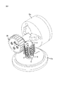
図1〜7は、歯を有するワークピースWを歯切りするために、より厳密には、いわゆるホブ切りをするために形成された切削器具の実施形態を示す。この切削器具は、歯車、ラック、スプライン(splines)、油圧ポンプのインペラ及び類似の歯付きの要素などの様々なワークピースWを切削加工するのに適している。切削器具は、スチールから製造されてもよい器具本体1と、交換可能な多数の切削インサート2とを具備する。
1 to 7 show an embodiment of a cutting tool formed for cutting a workpiece W with teeth, more precisely for so-called hobbing. This cutting tool is suitable for cutting various workpieces W such as gears, racks, splines, hydraulic pump impellers and similar toothed elements. The cutting tool comprises a
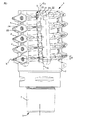
器具本体1は、回転軸線C1を画定し、固定端部3と反対側の外側端部4とを有する。回転軸線C1は、固定端部3と外側端部4とを通って延びる。図5を参照すると、固定端部3には、フライス又は多重作動機械(multioperation machine)の器具スピンドルS1に器具本体1及び切削工具を固定するための締結ピン5が存在する。器具本体1は、回転方向R1(器具スピンドルS1の内部から見て右に時計回り回転)に、回転軸線C1回りに回転することができる。
The
ワークピースWは、ワークピーススピンドルS3に固定され、回転方向R3に回転軸線C3回りに回転することができる。示されている実施形態では、ワークピースWは、外側から見て右に時計回りに回転する。 Workpiece W is fixed to the workpiece spindle S 3, it can be rotated on the rotation axis C 3 around the rotation direction R 3. In the embodiment shown, the workpiece W rotates clockwise as viewed from the outside.
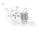
器具本体1は外周面7を有し、外周面7は、固定端部3と外側端部4との間、より厳密には、図4及び図5を参照して外側端部4から締結ピン5までの範囲において、回転軸線C1の周囲に拡がる。器具本体1は、外周面7に複数の細長凹部8を具備する。示されている実施形態では、切削器具はこのような凹部8を6つ備える。しかしながら、切削器具は、他の数の凹部8、例えば4つ、5つ、7つ又は8つの凹部8を備えてもよいことに留意されたい。
The instrument
特に図4〜7を参照すると、器具本体1はさらに、外周面7に配置された多数の分離した座9を備える。切削インサート2のうちの1つを受容するための各座9が形成される。図5を参照すると、座9及び切削インサート2が一定のピッチを有するらせん状の線xに沿って交互に配置されている。示されている実施形態では、らせん状の線xのピッチ方向は右向きである。ピッチ方向はまた、製造される歯によっては左向きであってもよい。らせん状の線のピッチ角βは1〜10°でもよい。
With particular reference to FIGS. 4 to 7, the
各座9は、切削インサート2を支持することができ又は支持するように構成された支持面10を備える。各座9はさらに、外周面7から内向きに延びるポケット11と、外周面7から突出する突出部12とを備える。支持面10の一部は突出部12から形成される。図1〜3を参照すると、切削インサート2は、座9に取り付けられると、ワークピースWの溝と切削係合するために、突出部12を越えて工具本体1から突出する。
Each
図7を参照すると、各ポケット11は支持面10及び内側限定壁13によって限定され、内側限定壁13は、切削インサート2が座9に取り付けられたときに、限定壁13と切削インサート2との間に間隙14が存在するように形成される。
Referring to FIG. 7, each
各座9の支持面10は、支持面10から延びる突状部を具備する。突状部は、主に半径方向に延びる第一の細長隆起部16と、主に軸線方向に延びる第二の細長隆起部17とを具備する。第一の細長隆起部16は、直角に、又は本質的に直角に第二の細長隆起部17と交差する。各細長隆起部16,17は、本質的に平坦であると共に支持面10に対して平行である上面18と、上面18を支持面10と接続する2つの斜面19とを有する。2つの斜面19は互いに鈍角を形成する。この角度は、90〜140°例えば120°であってもよい。
The
これより、図8〜19を参照して、切削インサート2のうちの1つがさらに詳細に説明される。切削器具の全ての切削インサート2が同一のものであってもよいものの、切削器具における様々な位置に様々な切削インサートを使用することもできることに留意されたい。
Now, one of the cutting inserts 2 will be described in more detail with reference to FIGS. It should be noted that although all cutting
切削インサート2は、器具本体1よりも硬い材料、例えば超硬合金から製造される。切削インサート2は、下側部21と、反対側の上側部22と、上側部22と下側部21とを接続して逃げ面を形成する外周刃側部23とを具備する。上側部22は、チップ面を形成し、延長平面pにおいて又は延長平面pと平行に拡がる。さらに、切削インサート2の下側部21は、上側部22の延長平面p又はチップ面と平行な延長平面において拡がる。図8〜12に示されている切削インサート2の第一の変形例は、延長平面pと全体的に一致する上側部22を有し、それにより、チップ面は全体的に平坦である。
The cutting
示された実施形態及び図8〜19の様々な変形例では、各切削インサート2は、刃側部23が上側部22又はチップ面と交わる箇所に形成された2つの切刃である、第一の切刃24と対向する第二の切刃25とを備える。第一の切刃24は、第一の主切刃24’と、第二の主切刃24”と、第一の主切刃24’と第二の主切刃24”との間を延びる横断端切刃24aとを具備する。第二の切刃25は、第一の主切刃25’と、第二の主切刃25”と、第一の主切刃25’と第二の主切刃25”との間を延びる横断端切刃25aとを具備する。したがって、切削インサート2は、4つの主切刃24’,24”,25’,25”を具備する。
In the illustrated embodiment and the various variants of FIGS. 8-19, each cutting
示されている実施形態では、切削インサート2は、延長平面pが上述の切刃24,25を含むように形成される。中心軸線Aは上側部21と下側部22とを通過して延びる。対称線Sは、中心軸線Aに対して垂直であり、延長平面pに対して平行に延びる。第一の主切刃24’及び第二の主切刃24”は、対称線Sに対して対称的に配置され、端切刃24aの外側の点に向かって収束する。したがって、この点は、中心軸線Aからよりも端切刃24aからさらに離れた距離にある。第一の主切刃25’及び第二の主切刃25”も、対称線Sに対して対称的に配置され、端切刃25aの外側の点に向かって収束する。したがって、この点は、中心軸線Aからよりも端切刃25aからさらに離れた距離にある。端切刃24a,25aのそれぞれは、対称線Sに対して垂直又は実質的に垂直である直線的なものであってもよく、好ましくは対称線Sに対して垂直又は実質的に垂直である直線的区域を具備してもよい。したがって、2つの端切刃24a,25a又はこれらの直線的区域は、互いに平行、又は互いに実質的に平行である。こうした直線的区域とそれぞれの第一及び第二の主切刃24’,24”,25’,25”との間において、小さい曲率半径の移行刃が存在してもよい。
In the embodiment shown, the cutting
各切削インサート2は、反対の2つの挿入位置同士の間で中心軸線A回りの回転によって換装することができる。第一の挿入位置では、第一の切刃24が切削工具から突出し、第二の挿入位置では、第二の切刃25が切削工具から突出する。
Each cutting
切削インサート2の下側部21は、下側部21から延びる凹部を有する。凹部は、第一の細長窪み部26と、各挿入位置に対するものである2つの第二の細長窪み部27とを具備する。第一の細長窪み部26は、対称線Sに対して平行に延び、切削インサート2が切削工具に取り付けられると主に半径方向に延びる。第二の細長窪み部27は、第一の細長窪み部26と直角に又は本質的に直角に交差し、切削インサート2が切削工具に取り付けられると主に軸線方向に延びる。
The
各細長窪み部26,27は、底面28及び2つの斜面29を具備する。斜面29は底面28を下側部21に接続する。これらの底面28及び斜面29は、切削インサート2が座9に取り付けられると上面18及び斜面19と協働する。斜面29は、互いに鈍角を形成する。この角度は、斜面19同士の鈍角と同一又は等しい。
Each
したがって、第一の細長窪み部26は、支持面10の対応する第一の細長隆起部16と係合するように形成される。第二の細長窪み部27は、支持面10の第二の細長隆起部17と係合するように形成される。したがって、切削インサート2が座9に取り付けられたときに、第一の細長隆起部16及び第一の細長窪み部26は互いに係合する。第二の細長隆起部17は、第二の細長窪み部27のうちの1つと係合する。それにより、斜面19は、斜面29に対して当接する。上面18と底面28との間に間隙があってもよい。
Accordingly, the first
各切削インサート2は、上側部22及び下側部21を通過する中心軸線Aと平行に延びる締結孔30を具備する。示されている実施形態では、中心軸線Aが締結孔30の中心軸線も形成する。切削インサート2は、支持面10に対して固定ネジ31によって座9に締結され、固定ネジ31は、締結孔30を通過して、支持面10を通過して延びるネジ孔32内部で延びる。図4を参照すると、ネジ孔32は、第二の細長隆起部17の半径方向外側に位置し、第一の細長隆起部16を通過して延びる。
Each cutting
換装可能な切削インサート2の上側部22は、対称線Sと一致する比較的長い対角線と、比較的長い対角線及び対称線Sに対して垂直である比較的短い対角線とを含む基本的に菱形の、又はほぼ菱形の形状を有する。図11を参照すると、対称線Sは、主切刃24’,24”,25’,25”のそれぞれと共に圧力角αを形成する。圧力角αは18〜32°の間にある。示されている実施形態では、圧力角αは、20°に等しく、又は本質的に等しい。別の実施形態では、圧力角αは、30°に等しく、又は本質的に等しい。この圧力角のサイズは、製造される溝に依存する。
The
図4〜6に示されているように、上述のポケット11は、回転軸線C1向きに内向きに対面しているかによって決まる、第一の切刃24又は第二の切刃25のための保護具を形成する。座9及び結果的に切削インサート2も複数の列に配置される。示されている切削器具は、切削インサート2のこのような6つの列を備える。しかしながら、切削器具は、別の数の切削インサート2の列、例えば、4、5、7又は8列の切削インサート2の列を備えることができることに留意されたい。各列は、少なくとも2つの切削インサート2及び座9を備える。示されている実施形態では、各列が5つの切削インサート2及び座9を備える。図1〜5に示されているように、各凹部8は、切削インサート2及び座9の各列に対して平行に延びる。図1〜3に示されているように、各凹部8は、このような列の切削インサート2のチップ面に切屑受容空間を形成するように、それぞれの列に隣接する。
As shown in FIGS. 4-6, a
図2及び図5を参照すると、切削インサート2及び座9の各列はそれぞれの線Lに沿って延び、線Lはらせん状の線xの接線に対して垂直である。座9及び切削インサート2の隣接する列同士の間の距離は等距離であり、すなわち、この距離は各対の列に対して等しい。さらに、らせん状の線xに沿って隣接する切削インサート2同士の間の距離も等距離であり、すなわち、この距離も各対の隣接する切削インサート2に対して等しい。
2 and 5, each row of cutting
切削器具の各切削インサート2のチップ面の延長平面pは、らせん状の線xが延長平面pと交差する箇所における、らせん状の線xの接線に対して平行な法線を有する。このことは、同じ列の隣接する対の切削インサート2の延長平面pが互いに或る角度を形成することを意味し、このことは図3に示されている。この形状によって、切削加工の十分なクリアランスを保証するために、切削インサート2はポジティブの切刃幾何学形状でもって形成される。このことは、上側部の延長平面p又はチップ面に対する法線が、少なくとも主切刃25に近い刃側部と逃げ角δを形成することを意味する。図12を参照されたい。逃げ角δはゼロよりも大きい。
The extension plane p of the chip surface of each cutting
第二の実施形態によれば、図13に示されている切削インサート2は、図8〜12に示されている切削インサートとは、この切削インサートがいわゆるプロチュバランス付き切削加工(protuberance cutting)のために形成されているという点で異なる。このような突出部を提供するために、第一の主切刃24’,25’は、それぞれの端切刃24a,25aの近くに第一の外側端偏向部37’,38’をそれぞれ備える。同様に、第二の主切刃24”,25”は、それぞれの端切刃24a,25aの近くに第二の外側端偏向部37”,38”をそれぞれ備える。したがって、第一及び第二の外側端偏向部37’,37”,38’,38”は、延長平面pにおいて延びる、又はこれに対して平行に延びる突出挿入刃を形成する。こうした突出挿入刃により、ワークピースWの溝の底面の近くでより深く又はより広く切り出すことができる。
According to the second embodiment, the cutting
第三の実施形態によれば、図14に示されている切削インサート2は、図13に示されている切削インサートとは、この切削インサートがいわゆるエッジチャンファ・インボリュート切削加工のために形成されているという点で異なる。第一の主切刃24’,25’が比較的短い対角線の近くに第一の内側端偏向部39’,40’をそれぞれ備えることと、第二の主切刃24”,25”が比較的短い対角線の近くに第二の内側端偏向部39”,40”をそれぞれ備えることとによって、そのようなエッジチャンファ・インボリュート切削加工を提供することができる。図14に示されているように、内側端偏向部39’,39”,40’,40”は短い対角線まで延びる。第一及び第二の内側端偏向部39’,39”,40’,40”は、延長平面pにおいて延び、又はこれに平行に延びる。
According to the third embodiment, the cutting
第四の実施形態によれば、図15に示されている切削インサート2は、図14に示されている切削インサートとは、この切削インサートがプロチュバランス付き切削加工のための偏向部を持たないという点のみで異なる。
According to the fourth embodiment, the cutting
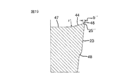
第五の実施形態によれば、図16〜19に示されている切削インサート2は、図8〜15に示されている切削インサートとは、この切削インサートが上側部22に切屑形成手段を伴って形成されているという点で異なる。示されている実施形態では、こうした切屑形成手段は、第一の切刃24の内側に位置する補強ベベル46から下向きに拡がる下向き斜面部分43と、第二の切刃25の内側に位置する補強ベベル46から下向きに拡がる下向き斜面部分44とを備える。
According to the fifth embodiment, the cutting
示されている補強ベベル46は、第一及び第二の主切刃24’,24”,25’,25”と端切刃24a,25aとから内向きに拡がる。このような補強ベベル46を第一の主切刃24’,25’に沿ってのみ配置できることに留意されたい。あるいは、補強ベベルは、2つの主切刃には沿うが、端切刃24a,25aには沿わないで拡がることができる。
The illustrated
第五の実施形態では、補強ベベル46は、第一及び第二の主切刃24’,24”,25’,25”を横切る幅b’、b”を有する。第一の主切刃24’,25’に沿ったこの幅b’は、第二の主切刃24”,25”に沿った幅b”よりも広い。図17〜19を参照されたい。このように、切削インサート2は、第一の主切刃24’,25’に沿った補強ベベル46の広い方の幅b’によって非対称の構成を得る。第一の主切刃24’,25’には、第二の主切刃24”,25”よりも高い荷重が付与される。第二の主切刃24”,25”の狭い方の補強ベベル46は、第一の主切刃24’,25’の広い方の補強ベベル46よりも低い切削抵抗を提供する。それにより、示されている実施形態は、強度及びエネルギ消費に対して切削インサート2を最適化することを意味する。
In the fifth embodiment, the reinforcing
第五の実施形態では、補強ベベル46は平坦または実質的に平坦である。補強ベベル46は延長平面pにおいて拡がる。しかしながら、補強ベベル46を、少なくとも第一の主切刃24’,25’から上向きに延ばすことができる。したがって、補強ベベル46は、0°から例えば2°までの範囲で、延長平面pに対する角度を有することができる。
In the fifth embodiment, the reinforcing
切屑形成手段、つまり斜面部分43,44は、歯割りの際に形成された切屑を曲げ破壊するように形成される。斜面部分43,44は、延長平面pに対して5°〜25°の角度で下向きに傾くことができる。斜面部分43,44はさらに複数の区域を有してもよく、これらの区域は、切刃24,25から相次いで配置され、延長平面pに対して様々な傾斜を有してもよい。示されている実施形態では、斜面部分43,44は、或る曲率半径rを有することができる湾曲した移行面を介して、上側部22の平坦中央面47に移行する。
The chip forming means, that is, the
第五の実施形態による切削インサート2にはさらに、刃側部23にステップ48が提供される。適切な逃げ面は、第一及び第二の切刃24,25からステップ48まで、固定した鋭角の逃げ角δで拡がる。ステップ48の下において下側部21までずっと、刃側部23は任意の形状を有することができる。
The cutting
本発明は、上述の実施形態に限られないが、後の特許請求の範囲内において本発明を変形しかつ変更することができる。 The present invention is not limited to the embodiments described above, but can be modified and changed within the scope of the following claims.
例えば、1又は複数の座9は、換装可能な差込体若しくはカセットであってもよく、又はこれらから形成されてもよい。支持面10も、交換可能なシムプレート上に形成されてもよく、又はこれから形成されてもよい。さらに、1又は複数の切削インサート2は示された締結孔を持たず、代わりに、例えば切削インサート2の上側部22を押圧する締め付け部材によってそれぞれの座9に、1又は複数の切削インサート2を締結することができる。
For example, the seat or
図8〜19に示された様々な実施形態を、様々なやり方で互いに組み合わせられることに留意されたい。第五の実施形態に形成されたタイプの補強ベベル46を、例えば、図13〜15に示された実施形態に提供することができる。当然に、図13〜15に示された実施形態は、第五の実施形態に示されたタイプのステップ48を具備することもできる。図13〜15に示されているように、第五の実施形態による切削インサートが一定の逃げ角を有する刃側部23を有することにも留意されたい。さらに、切削インサート2が換装可能である必要はないことに留意されたい。切削インサート2に第一の切刃24を提供して、第二の切刃25なしで済ますことができる。したがって、第一の切刃24から離れて対面する切削インサート2の部分は、任意の形状を有することができ、例えば、この部分に、切削器具の座に当接して切削器具の回転軸線C1に対する切削インサート2の半径方向位置を保証する後方当接面を設けることができる。この実施形態において、場合により締結孔30を任意の位置に配置することができる。例えば、換装可能な実施形態ではなく、端切刃33の近くに締結孔を配置することができる。
It should be noted that the various embodiments shown in FIGS. 8-19 can be combined with each other in various ways. A reinforcing
1 器具本体
2 切削インサート
3 固定端部
4 外側端部
5 締結ピン
7 外周面
8 凹部
9 座
10 支持面
11 ポケット
12 突出部
13 限定壁
14 間隙
16 第一の細長隆起部
17 第二の細長隆起部
18 上面
19 斜面
21 下側部
22 上側部
23 刃側部
24 第一の切刃
24’ 第一の主切刃
24” 第二の主切刃
24a 端切刃
25 第二の切刃
25’ 第一の主切刃
25” 第二の主切刃
25a 端切刃
26 第一の細長窪み部
27 第二の細長窪み部
28 底面
29 斜面
30 締結孔
31 固定ネジ
32 ネジ孔
37’ 第一の外側端偏向部
37” 第二の外側端偏向部
38’ 第一の外側端偏向部
38” 第二の外側端偏向部
39’ 第一の内側端偏向部
39” 第二の内側端偏向部
40’ 第一の内側端偏向部
40” 第二の内側端偏向部
43 斜面部分
44 斜面部分
46 補強ベベル
47 中央面
48 ステップ
W ワークピース
C1 回転軸線
R1 回転方向
C3 回転軸線
R3 回転方向
S1 器具スピンドル
S3 ワークピーススピンドル
A 中心軸線
S 対称線
p 延長平面
x らせん状の線
α 圧力角
β ピッチ角
r 曲率半径
δ 逃げ角
b’ 幅
b” 幅
DESCRIPTION OF
Claims (14)
下側部(21)と、
チップ面を形成すると共に延長平面(p)に対して平行に拡がる、反対側の上側部(22)と、
上側部(22)と下側部(21)とを接続する周囲刃側部(23)と、
下側部(21)と上側部(22)とを通過して延びる中心軸線(A)と、
中心軸線(A)に対して垂直でありかつ中心軸線(A)と交差する対称線(S)と、
対称線(S)に対して対称的であると共に刃側部(23)がチップ面と交わる箇所に形成される第一の主切刃(24’)及び第二の主切刃(24”)と、第一の主切刃(24’)と第二の主切刃(24”)との間に延びると共に直線的区域を具備する横断端切刃(24a)とを具備する第一の切刃(24)と、
を具備し、
切削インサート(2)がポジティブの切刃幾何学形状を得るように、延長平面(p)の法線が少なくとも第一の切刃(24)に沿う刃側部(23)と鋭角の逃げ角(δ)を形成する、
切削インサートにおいて、
チップ面は、前記第一の主切刃(24’)のみから内向きに延びる補強ベベル(46)を具備することと、
チップ面は、少なくとも前記第一及び第二の主切刃(24’,24”,25’,25”)から内向きに延びる補強ベベル(46)を具備し、補強ベベル(46)は、前記第一及び第二の主切刃(24’,24”,25’,25”)を横切る幅(b’,b”)を有し、第一の主切刃(24’,25’)に沿う幅(b’)は、第二の主切刃(24”,25”)に沿う幅(b”)よりも広いことと、
のいずれか一方を含み、
さらに、下側部(22)は、下側部(22)から延びると共に切削器具の支持面(10)の対応する保護部と係合するように配置された凹部を有する、
切削インサート。 A cutting insert (2) for a cutting tool formed to split a workpiece (W) in the form of a hob so as to have teeth,
The lower side (21);
An opposite upper part (22) that forms a chip surface and extends parallel to the extension plane (p);
A peripheral blade side part (23) connecting the upper part (22) and the lower part (21);
A central axis (A) extending through the lower part (21) and the upper part (22);
A symmetry line (S) perpendicular to the central axis (A) and intersecting the central axis (A);
A first main cutting edge (24 ') and a second main cutting edge (24 ") which are symmetrical with respect to the symmetry line (S) and are formed at a position where the blade side portion (23) intersects the chip surface. And a first end cutting edge (24a) extending between the first main cutting edge (24 ') and the second main cutting edge (24 ") and having a straight section. A blade (24);
Equipped with,
In order for the cutting insert (2) to obtain a positive cutting edge geometry, the normal of the extension plane (p) is at least the blade side (23) along the first cutting edge (24) and an acute clearance angle ( δ),
In cutting inserts,
The tip surface comprises a reinforcing bevel (46) extending inwardly only from the first main cutting edge (24 ');
The tip surface comprises a reinforcing bevel (46) extending inwardly from at least the first and second main cutting edges (24 ', 24 ", 25', 25"), and the reinforcing bevel (46) The first main cutting edge (24 ', 25') has a width (b ', b ") across the first and second main cutting edges (24', 24", 25 ', 25 "). The width (b ′) along is wider than the width (b ″) along the second main cutting edge (24 ″, 25 ″);
Including either
Furthermore, the lower part (22) has a recess that extends from the lower part (22) and is arranged to engage with a corresponding protective part of the support surface (10) of the cutting tool,
Cutting insert.
請求項1に記載の切削インサート。 The straight section extends perpendicular to the symmetry line (S),
The cutting insert according to claim 1.
圧力角(α)は18〜32°の間である、
請求項1及び請求項2のいずれか1項に記載の切削インサート。 A symmetry line (S) forms a pressure angle (α) with each of the first and second main cutting edges (24 ′, 24 ″, 25 ′, 25 ″),
The pressure angle (α) is between 18 and 32 °,
The cutting insert according to any one of claims 1 and 2.
請求項1〜3のいずれか1項に記載の切削インサート。 The reinforcing bevel (46) extends upward from at least the first main cutting edge (24 ', 25'),
The cutting insert according to any one of claims 1 to 3 .
請求項1〜4のいずれか1項に記載の切削インサート。 The chip surface comprises chip forming means formed so as to bend and break the chip formed at the time of tooth splitting.
The cutting insert according to any one of claims 1 to 4 .
請求項5に記載の切削インサート。 The tip forming means includes slope portions (43, 44) that are inclined downward and extend inwardly from the reinforcing bevel (46).
The cutting insert according to claim 5 .
第二の主切刃(24”,25”)は、端切刃(24a,25a)に隣接する第二の外側端偏向部(37”)をそれぞれ具備する、
請求項1〜6のいずれか1項に記載の切削インサート。 The first main cutting edges (24 ′, 25 ′) each include a first outer end deflection portion (37 ′) adjacent to the end cutting edges (24a, 25a),
The second main cutting edge (24 ″, 25 ″) includes a second outer end deflection portion (37 ″) adjacent to the end cutting edge (24a, 25a), respectively.
The cutting insert according to any one of claims 1 to 6 .
請求項7に記載の切削インサート。 The first and second outer end deflection portions (37 ′, 37 ″) extend parallel to the extension plane (p).
The cutting insert according to claim 7 .
第二の切刃(25)は、対称線(S)に対して対称的であると共に刃側部(23)がチップ面と交わる箇所に形成される第一の主切刃(25’)及び第二の主切刃(25”)と、第一の主切刃(25’)と第二の主切刃(25”)との間で延びる横断端切刃(25a)とを具備し、
第一の切刃(24)がワークピース(W)と係合する第一の挿入位置と、第二の切刃(25)がワークピース(W)と係合する第二の挿入位置との間において、中心軸線(A)回りに回転することによって換装可能である、
請求項1〜8のいずれか1項に記載の切削インサート。 Comprising a second cutting edge (25),
The second cutting edge (25) is symmetrical with respect to the symmetry line (S) and has a first main cutting edge (25 ′) formed at a location where the blade side portion (23) intersects the chip surface and A second main cutting edge (25 ") and a transverse end cutting edge (25a) extending between the first main cutting edge (25 ') and the second main cutting edge (25");
A first insertion position where the first cutting edge (24) engages with the workpiece (W) and a second insertion position where the second cutting edge (25) engages with the workpiece (W). Can be replaced by rotating around the central axis (A),
The cutting insert of any one of Claims 1-8 .
請求項9に記載の切削インサート。 The upper part of the cutting insert (2) has a basically rhombic shape with a relatively long diagonal line coincident with the symmetry line (S) and a relatively short diagonal line perpendicular to the relatively long diagonal line,
The cutting insert according to claim 9 .
第二の主切刃(24”,25”)は、比較的短い対角線の近くに第二の内側端偏向部(39”,40”)をそれぞれ具備する、
請求項9及び請求項10のいずれか1項に記載の切削インサート。 The first main cutting edges (24 ′, 25 ′) are each provided with a first inner end deflection portion (39 ′, 40 ′) near a relatively short diagonal,
The second main cutting edges (24 ", 25") are each provided with a second inner end deflection (39 ", 40") near a relatively short diagonal,
The cutting insert according to any one of claims 9 and 10 .
請求項11に記載の切削インサート。 The first and second inner end deflection portions (39 ′, 39 ″, 40 ′, 40 ″) extend parallel to the extension plane (p).
The cutting insert according to claim 11 .
締結孔(30)を通過して切削器具のネジ孔(32)内部を延びる固定ネジ(31)により切削器具の座(9)に取り付けられるように形成される、
請求項1〜12のいずれか1項に記載の切削インサート。 A fastening hole (30) extending through the upper part (22) and the lower part (21);
It is formed to be attached to the seat (9) of the cutting tool by a fixing screw (31) passing through the fastening hole (30) and extending inside the screw hole (32) of the cutting tool.
Cutting insert according to any one of claims 1 to 12.
第一の細長窪み部(26)は対称線(S)に対して平行に延び、
第二の細長窪み部(27)は第一の細長窪み部(26)と交差する、
請求項1〜13のいずれか1項に記載の切削インサート。 The recess comprises a first elongated recess (26) and two second elongated recesses (27),
The first elongated recess (26) extends parallel to the symmetry line (S),
The second elongated depression (27) intersects the first elongated depression (26);
The cutting insert according to any one of claims 1 to 13 .
Applications Claiming Priority (2)
| Application Number | Priority Date | Filing Date | Title |
|---|---|---|---|
| SE1150112-9 | 2011-02-11 | ||
| SE1150112A SE535541C2 (en) | 2011-02-11 | 2011-02-11 | Cutting insert for a milling tool designed for tooth milling |
Publications (3)
| Publication Number | Publication Date |
|---|---|
| JP2012166335A JP2012166335A (en) | 2012-09-06 |
| JP2012166335A5 JP2012166335A5 (en) | 2015-01-22 |
| JP5926066B2 true JP5926066B2 (en) | 2016-05-25 |
Family
ID=45507587
Family Applications (1)
| Application Number | Title | Priority Date | Filing Date |
|---|---|---|---|
| JP2012027224A Expired - Fee Related JP5926066B2 (en) | 2011-02-11 | 2012-02-10 | Cutting insert for cutting tool |
Country Status (6)
| Country | Link |
|---|---|
| US (1) | US9283631B2 (en) |
| EP (1) | EP2487001B1 (en) |
| JP (1) | JP5926066B2 (en) |
| KR (1) | KR20120092521A (en) |
| CN (1) | CN102632302B (en) |
| SE (1) | SE535541C2 (en) |
Families Citing this family (23)
| Publication number | Priority date | Publication date | Assignee | Title |
|---|---|---|---|---|
| US8882404B2 (en) | 2009-02-27 | 2014-11-11 | No Screw Ltd | Cutting tool, cutting tool holder and cutting insert therefor |
| SE535540C2 (en) | 2011-02-11 | 2012-09-18 | Sandvik Intellectual Property | Milling tools for tooth milling |
| SE536590C2 (en) * | 2012-07-05 | 2014-03-11 | Sandvik Intellectual Property | Milling inserts with primary and secondary release surface as well as peripheral, narrow chip surface |
| SE537377C2 (en) * | 2012-07-05 | 2015-04-14 | Sandvik Intellectual Property | Cutting insert and milling tool for milling a groove in a workpiece |
| US9120156B2 (en) * | 2013-03-26 | 2015-09-01 | Iscar, Ltd. | Rhombus-shaped indexable cutting insert and cutting tool |
| SE1350827A1 (en) * | 2013-07-03 | 2015-01-04 | Sandvik Intellectual Property | Cutting insert and milling tools |
| US9475136B2 (en) * | 2013-07-30 | 2016-10-25 | Kennametal Inc. | High-speed milling cutter and cutting insert therefor |
| SE1350983A1 (en) * | 2013-08-27 | 2015-02-28 | Sandvik Intellectual Property | Tools and cutters for shell milling |
| CA2924757C (en) | 2013-09-03 | 2018-12-04 | No Screw Ltd. | Mounting mechanism for a cutting insert, a cutting insert therefor and a cutting tool using said insert |
| EP2871015B1 (en) * | 2013-11-11 | 2018-10-10 | Sandvik Intellectual Property AB | Gear milling cutter as well as an insert holder and a chip removal unit |
| RU2634565C2 (en) * | 2014-08-12 | 2017-10-31 | Валентин Алексеевич Настасенко | Built-up hyperboloid worm gear-cutting tool, replaceable rotary disposable cutting plates to equip thereof and method of their operation |
| EP2992991A1 (en) * | 2014-09-05 | 2016-03-09 | Sandvik Intellectual Property AB | Cutting insert and milling tool |
| EP3025814B1 (en) * | 2014-11-28 | 2017-08-02 | Sandvik Intellectual Property AB | A milling insert and a milling tool |
| US10307833B2 (en) | 2015-02-04 | 2019-06-04 | No Screw Ltd. | Cutting tool comprising a cutting tool holder and a cutting insert therefor |
| WO2016174663A1 (en) | 2015-04-30 | 2016-11-03 | No Screw Ltd. | Dynamic clamping mechanism |
| US20170014923A1 (en) * | 2015-07-14 | 2017-01-19 | Caterpillar Inc. | Dual Ended, Full Form Tooth Generating Gear Cutter and Associated Cutting Insert |
| DE102017131001A1 (en) | 2017-12-21 | 2019-06-27 | Hartmetall-Werkzeugfabrik Paul Horn Gmbh | Milling tool holder and milling tool |
| RU181245U1 (en) * | 2017-12-27 | 2018-07-06 | Андрей Владимирович Ничков | COMBINED MILL |
| RU187253U1 (en) * | 2017-12-27 | 2019-02-26 | Андрей Владимирович Ничков | COMBINED MILL |
| US10780512B2 (en) * | 2018-08-24 | 2020-09-22 | Gleason Cutting Tools Corporation | Multi-component gear cutting tool |
| GB2584296B (en) * | 2019-05-28 | 2022-04-13 | Gkn Aerospace Sweden Ab | An apparatus and method for machining an aeronautical component |
| CN110360244B (en) * | 2019-08-21 | 2023-08-22 | 山东雷沃传动有限公司 | Friction plate type overrunning clutch and loader comprising same |
| US11491560B1 (en) * | 2021-07-13 | 2022-11-08 | Taegutec Ltd. | Cutting insert and rotary cutting tool including same |
Family Cites Families (31)
| Publication number | Priority date | Publication date | Assignee | Title |
|---|---|---|---|---|
| US2698477A (en) * | 1952-12-31 | 1955-01-04 | Michigan Tool Co | Hob |
| AT301300B (en) * | 1969-08-13 | 1972-08-25 | Plansee Metallwerk | Hobs |
| JPS4919509Y1 (en) * | 1970-12-16 | 1974-05-24 | ||
| DE2159336A1 (en) * | 1970-12-16 | 1972-07-06 | Dijet Kogyo K K | CUTTER |
| US3766618A (en) | 1972-02-22 | 1973-10-23 | Illinois Tool Works | Composite hob |
| US3730561A (en) | 1972-04-17 | 1973-05-01 | F Temple | Swivel-type carrier for automatic air hose connector |
| US3892022A (en) | 1974-05-10 | 1975-07-01 | Barber Colman Co | Roughing hob |
| JPS522388U (en) * | 1975-06-24 | 1977-01-08 | ||
| JPS522388A (en) | 1975-06-24 | 1977-01-10 | Nippon Kogaku Kk <Nikon> | Luminous diode driving device |
| US4218159A (en) | 1977-01-07 | 1980-08-19 | Sack Gmbh | Multiple-part hobbing cutter |
| SE452563B (en) * | 1983-06-27 | 1987-12-07 | Santrade Ltd | KOPIERSKER |
| JPS60175526U (en) * | 1984-04-27 | 1985-11-20 | 株式会社神戸製鋼所 | Carbide hob for finishing |
| US5192171A (en) * | 1991-01-07 | 1993-03-09 | Gte Valenite Corporation | Chip control insert |
| DE4330484C2 (en) | 1993-09-09 | 1995-06-22 | Fette Wilhelm Gmbh | Hobbing cutters |
| DE59508102D1 (en) * | 1994-09-13 | 2000-05-04 | Widia Gmbh | CUTTING INSERT |
| JP3729634B2 (en) | 1998-03-10 | 2005-12-21 | 株式会社小松製作所 | Slowaway hob and manufacturing method thereof |
| JP4465809B2 (en) * | 1999-07-09 | 2010-05-26 | 三菱マテリアル株式会社 | Throwaway tip |
| AT3955U1 (en) * | 1999-09-09 | 2000-11-27 | Plansee Tizit Aktiengesellscha | ROTATING CUTTING TOOL |
| JP4616445B2 (en) | 2000-06-13 | 2011-01-19 | 株式会社タンガロイ | Comb blade type hob and comb blade |
| IL144138A (en) * | 2001-07-04 | 2006-06-11 | Daniel Ulianitsky | Milling cutter and cutting insert therefor |
| EP1497085B1 (en) | 2002-04-18 | 2009-11-18 | Kennametal Inc. | Gear hobbing cutter system |
| US7234901B2 (en) * | 2002-09-11 | 2007-06-26 | Kyocera Corporation | Throw-away tip |
| IL154649A (en) * | 2003-02-27 | 2007-10-31 | Uzi Gati | Cutting insert for grooving operations |
| SE527378C2 (en) * | 2003-05-08 | 2006-02-21 | Sandvik Intellectual Property | Cutters for turning have an edge phase |
| SE527851C2 (en) * | 2004-02-11 | 2006-06-20 | Sandvik Intellectual Property | Cutting tools, cutting tools and parts for cutting tools with serration coupling surfaces |
| SE528811C2 (en) | 2005-03-16 | 2007-02-20 | Sandvik Intellectual Property | Cuts and tools for chip separating machining with angled engaging means, and additives for such tools |
| SE530189C2 (en) * | 2006-04-25 | 2008-03-25 | Seco Tools Ab | Thread cutter with full surface of PCBN as well as threading tools and thread forming method |
| SE530289C2 (en) * | 2006-10-13 | 2008-04-22 | Seco Tools Ab | Negative lathe with a phase between cutting edge and release side |
| SE531858C2 (en) | 2007-12-21 | 2009-08-25 | Sandvik Intellectual Property | Milling tools for chip separating machining, as well as cutting body and basic body for this |
| SE533484C2 (en) * | 2009-02-20 | 2010-10-05 | Sandvik Intellectual Property | Rotary tool for chip separating machining and cutting for this |
| SE535540C2 (en) | 2011-02-11 | 2012-09-18 | Sandvik Intellectual Property | Milling tools for tooth milling |
-
2011
- 2011-02-11 SE SE1150112A patent/SE535541C2/en not_active IP Right Cessation
-
2012
- 2012-01-20 EP EP12151873.2A patent/EP2487001B1/en active Active
- 2012-01-27 US US13/359,595 patent/US9283631B2/en active Active
- 2012-02-10 KR KR1020120013617A patent/KR20120092521A/en not_active Application Discontinuation
- 2012-02-10 JP JP2012027224A patent/JP5926066B2/en not_active Expired - Fee Related
- 2012-02-10 CN CN201210030477.5A patent/CN102632302B/en active Active
Also Published As
| Publication number | Publication date |
|---|---|
| SE1150112A1 (en) | 2012-08-12 |
| US20120207555A1 (en) | 2012-08-16 |
| KR20120092521A (en) | 2012-08-21 |
| US9283631B2 (en) | 2016-03-15 |
| EP2487001B1 (en) | 2020-11-04 |
| CN102632302A (en) | 2012-08-15 |
| CN102632302B (en) | 2017-05-10 |
| JP2012166335A (en) | 2012-09-06 |
| EP2487001A3 (en) | 2017-01-18 |
| EP2487001A2 (en) | 2012-08-15 |
| SE535541C2 (en) | 2012-09-18 |
Similar Documents
| Publication | Publication Date | Title |
|---|---|---|
| JP5926066B2 (en) | Cutting insert for cutting tool | |
| JP5941689B2 (en) | Gear cutting tool | |
| JP6022798B2 (en) | Milling tools and milling insert kits | |
| US8961075B2 (en) | Milling tool as well as set of milling inserts of a milling tool | |
| JP4756408B2 (en) | Cutting insert and cutting edge replaceable cutting tool using the same | |
| JP2014014924A (en) | Milling insert and milling tool | |
| CN106964850B (en) | Cutting insert and cutting tool | |
| US9358621B2 (en) | Cutting insert and a milling tool | |
| US10220452B2 (en) | Formed rotary cutting tool | |
| JP2010089250A (en) | Cutting insert and insert removable rotary cutting tool | |
| CN103442832A (en) | Cutting insert and indexable rotary cutting tool | |
| JP5218811B2 (en) | Throwaway tip |
Legal Events
| Date | Code | Title | Description |
|---|---|---|---|
| A521 | Request for written amendment filed |
Free format text: JAPANESE INTERMEDIATE CODE: A523 Effective date: 20141203 |
|
| A621 | Written request for application examination |
Free format text: JAPANESE INTERMEDIATE CODE: A621 Effective date: 20141203 |
|
| A131 | Notification of reasons for refusal |
Free format text: JAPANESE INTERMEDIATE CODE: A131 Effective date: 20150901 |
|
| A601 | Written request for extension of time |
Free format text: JAPANESE INTERMEDIATE CODE: A601 Effective date: 20151130 |
|
| A521 | Request for written amendment filed |
Free format text: JAPANESE INTERMEDIATE CODE: A523 Effective date: 20160301 |
|
| TRDD | Decision of grant or rejection written | ||
| A01 | Written decision to grant a patent or to grant a registration (utility model) |
Free format text: JAPANESE INTERMEDIATE CODE: A01 Effective date: 20160322 |
|
| A61 | First payment of annual fees (during grant procedure) |
Free format text: JAPANESE INTERMEDIATE CODE: A61 Effective date: 20160421 |
|
| R150 | Certificate of patent or registration of utility model |
Ref document number: 5926066 Country of ref document: JP Free format text: JAPANESE INTERMEDIATE CODE: R150 |
|
| RD02 | Notification of acceptance of power of attorney |
Free format text: JAPANESE INTERMEDIATE CODE: R3D02 |
|
| LAPS | Cancellation because of no payment of annual fees |