JP5925604B2 - Cooling water control valve - Google Patents
Cooling water control valve Download PDFInfo
- Publication number
- JP5925604B2 JP5925604B2 JP2012126448A JP2012126448A JP5925604B2 JP 5925604 B2 JP5925604 B2 JP 5925604B2 JP 2012126448 A JP2012126448 A JP 2012126448A JP 2012126448 A JP2012126448 A JP 2012126448A JP 5925604 B2 JP5925604 B2 JP 5925604B2
- Authority
- JP
- Japan
- Prior art keywords
- cooling water
- rotor
- valve body
- angle
- output gear
- Prior art date
- Legal status (The legal status is an assumption and is not a legal conclusion. Google has not performed a legal analysis and makes no representation as to the accuracy of the status listed.)
- Active
Links
Images


Classifications
-
- F—MECHANICAL ENGINEERING; LIGHTING; HEATING; WEAPONS; BLASTING
- F01—MACHINES OR ENGINES IN GENERAL; ENGINE PLANTS IN GENERAL; STEAM ENGINES
- F01P—COOLING OF MACHINES OR ENGINES IN GENERAL; COOLING OF INTERNAL-COMBUSTION ENGINES
- F01P7/00—Controlling of coolant flow
- F01P7/14—Controlling of coolant flow the coolant being liquid
-
- F—MECHANICAL ENGINEERING; LIGHTING; HEATING; WEAPONS; BLASTING
- F01—MACHINES OR ENGINES IN GENERAL; ENGINE PLANTS IN GENERAL; STEAM ENGINES
- F01P—COOLING OF MACHINES OR ENGINES IN GENERAL; COOLING OF INTERNAL-COMBUSTION ENGINES
- F01P11/00—Component parts, details, or accessories not provided for in, or of interest apart from, groups F01P1/00 - F01P9/00
- F01P11/14—Indicating devices; Other safety devices
-
- F—MECHANICAL ENGINEERING; LIGHTING; HEATING; WEAPONS; BLASTING
- F16—ENGINEERING ELEMENTS AND UNITS; GENERAL MEASURES FOR PRODUCING AND MAINTAINING EFFECTIVE FUNCTIONING OF MACHINES OR INSTALLATIONS; THERMAL INSULATION IN GENERAL
- F16K—VALVES; TAPS; COCKS; ACTUATING-FLOATS; DEVICES FOR VENTING OR AERATING
- F16K11/00—Multiple-way valves, e.g. mixing valves; Pipe fittings incorporating such valves
- F16K11/02—Multiple-way valves, e.g. mixing valves; Pipe fittings incorporating such valves with all movable sealing faces moving as one unit
- F16K11/08—Multiple-way valves, e.g. mixing valves; Pipe fittings incorporating such valves with all movable sealing faces moving as one unit comprising only taps or cocks
- F16K11/085—Multiple-way valves, e.g. mixing valves; Pipe fittings incorporating such valves with all movable sealing faces moving as one unit comprising only taps or cocks with cylindrical plug
- F16K11/0853—Multiple-way valves, e.g. mixing valves; Pipe fittings incorporating such valves with all movable sealing faces moving as one unit comprising only taps or cocks with cylindrical plug having all the connecting conduits situated in a single plane perpendicular to the axis of the plug
-
- F—MECHANICAL ENGINEERING; LIGHTING; HEATING; WEAPONS; BLASTING
- F16—ENGINEERING ELEMENTS AND UNITS; GENERAL MEASURES FOR PRODUCING AND MAINTAINING EFFECTIVE FUNCTIONING OF MACHINES OR INSTALLATIONS; THERMAL INSULATION IN GENERAL
- F16K—VALVES; TAPS; COCKS; ACTUATING-FLOATS; DEVICES FOR VENTING OR AERATING
- F16K3/00—Gate valves or sliding valves, i.e. cut-off apparatus with closing members having a sliding movement along the seat for opening and closing
- F16K3/22—Gate valves or sliding valves, i.e. cut-off apparatus with closing members having a sliding movement along the seat for opening and closing with sealing faces shaped as surfaces of solids of revolution
- F16K3/24—Gate valves or sliding valves, i.e. cut-off apparatus with closing members having a sliding movement along the seat for opening and closing with sealing faces shaped as surfaces of solids of revolution with cylindrical valve members
-
- F—MECHANICAL ENGINEERING; LIGHTING; HEATING; WEAPONS; BLASTING
- F16—ENGINEERING ELEMENTS AND UNITS; GENERAL MEASURES FOR PRODUCING AND MAINTAINING EFFECTIVE FUNCTIONING OF MACHINES OR INSTALLATIONS; THERMAL INSULATION IN GENERAL
- F16K—VALVES; TAPS; COCKS; ACTUATING-FLOATS; DEVICES FOR VENTING OR AERATING
- F16K31/00—Actuating devices; Operating means; Releasing devices
- F16K31/02—Actuating devices; Operating means; Releasing devices electric; magnetic
- F16K31/04—Actuating devices; Operating means; Releasing devices electric; magnetic using a motor
- F16K31/041—Actuating devices; Operating means; Releasing devices electric; magnetic using a motor for rotating valves
- F16K31/043—Actuating devices; Operating means; Releasing devices electric; magnetic using a motor for rotating valves characterised by mechanical means between the motor and the valve, e.g. lost motion means reducing backlash, clutches, brakes or return means
-
- F—MECHANICAL ENGINEERING; LIGHTING; HEATING; WEAPONS; BLASTING
- F01—MACHINES OR ENGINES IN GENERAL; ENGINE PLANTS IN GENERAL; STEAM ENGINES
- F01P—COOLING OF MACHINES OR ENGINES IN GENERAL; COOLING OF INTERNAL-COMBUSTION ENGINES
- F01P7/00—Controlling of coolant flow
- F01P7/14—Controlling of coolant flow the coolant being liquid
- F01P2007/146—Controlling of coolant flow the coolant being liquid using valves
-
- F—MECHANICAL ENGINEERING; LIGHTING; HEATING; WEAPONS; BLASTING
- F01—MACHINES OR ENGINES IN GENERAL; ENGINE PLANTS IN GENERAL; STEAM ENGINES
- F01P—COOLING OF MACHINES OR ENGINES IN GENERAL; COOLING OF INTERNAL-COMBUSTION ENGINES
- F01P3/00—Liquid cooling
- F01P3/20—Cooling circuits not specific to a single part of engine or machine
-
- F—MECHANICAL ENGINEERING; LIGHTING; HEATING; WEAPONS; BLASTING
- F01—MACHINES OR ENGINES IN GENERAL; ENGINE PLANTS IN GENERAL; STEAM ENGINES
- F01P—COOLING OF MACHINES OR ENGINES IN GENERAL; COOLING OF INTERNAL-COMBUSTION ENGINES
- F01P7/00—Controlling of coolant flow
- F01P7/14—Controlling of coolant flow the coolant being liquid
- F01P7/16—Controlling of coolant flow the coolant being liquid by thermostatic control
- F01P7/167—Controlling of coolant flow the coolant being liquid by thermostatic control by adjusting the pre-set temperature according to engine parameters, e.g. engine load, engine speed
Description
本発明は、エンジンの冷却水の流れを制御する冷却水制御弁に関する。 The present invention relates to a cooling water control valve that controls the flow of cooling water in an engine.
自動車等の車両のエンジン(内燃機関)においては、エンジンの暖機性能の向上やエンジンを最適な温度で動作させることによる燃費向上等を目的として、エンジンとラジエータとの間で冷却水を循環させるメイン通路とは別に、ラジエータをバイパスしてそのままエンジンに戻すバイパス通路を設けるとともに、メイン通路に冷却水制御弁を設け、この冷却水制御弁の開度を冷却水温度とその他の値に応じて調節することによって、メイン通路を流れてラジエータによって冷却される冷却水の量を制御することが検討されている。なお、冷却水は、エンジンにより駆動されるポンプにより循環させられており、エンジン作動中で、かつ、冷却水制御弁が開いている場合は、冷却水が主にメイン通路を循環し、冷却水制御弁が閉じられている場合にバイパス通路を循環する。 In an engine (an internal combustion engine) of a vehicle such as an automobile, cooling water is circulated between the engine and the radiator for the purpose of improving the warm-up performance of the engine and improving the fuel consumption by operating the engine at an optimum temperature. In addition to the main passage, a bypass passage that bypasses the radiator and returns to the engine is provided, and a cooling water control valve is provided in the main passage, and the opening degree of the cooling water control valve is set according to the cooling water temperature and other values. By adjusting, it has been studied to control the amount of cooling water flowing through the main passage and cooled by the radiator. The cooling water is circulated by a pump driven by the engine. When the engine is operating and the cooling water control valve is open, the cooling water mainly circulates through the main passage, Circulates the bypass passage when the control valve is closed.
例えば、冷却水温が低いエンジン始動時等においては、メイン通路を遮断して冷却水をラジエータに通さずにバイパス通路からエンジンにそのまま戻し、エンジンの暖機を促進させるようにする。また、例えば、暖気後もエンジンにおける燃料の燃焼を最適化するように冷却水の温度を制御するために、冷却水制御弁の開閉(開度)を調整する。
このような冷却水制御弁では、ロータリ式バルブなどの使用が検討されている。
For example, at the time of engine start or the like where the cooling water temperature is low, the main passage is shut off and the cooling water is not returned to the radiator but returned to the engine as it is to promote engine warm-up. Further, for example, in order to control the temperature of the cooling water so as to optimize the combustion of fuel in the engine even after warming up, the opening / closing (opening) of the cooling water control valve is adjusted.
For such a cooling water control valve, use of a rotary valve or the like is being studied.
ロータリ式バルブでは、例えば、ロータ内に流路が設けられるとともに、ロータを収容するハウジングに、外部の流路に接続され、かつ、ロータの角度が開となる角度の場合に、ロータ内の流路と連通する開口部が形成されている。このロータの回転角度により、冷却水制御弁が開閉するとともに、開度が調整されて流量が調整されることになる。 In a rotary valve, for example, a flow path in the rotor is provided when a flow path is provided in the rotor, a housing that accommodates the rotor is connected to an external flow path, and the angle of the rotor is an open angle. An opening communicating with the road is formed. Depending on the rotation angle of the rotor, the coolant control valve opens and closes, and the opening degree is adjusted to adjust the flow rate.
したがって、例えば、冷却水制御弁の組立時や、完成後の冷却水制御弁の作動開始時等において、全閉位置や全開位置等の角度のイニシャライズ学習が必要である。例えば、エンジン水温を調整するエンジンの冷却系制御装置において、サーモ弁、ヒータ弁、オイル弁について、通電開始時に弁を全開から全閉とするイニシャル処理を行うことが提案されている(例えば、特許文献1参照)。 Therefore, for example, when the cooling water control valve is assembled or when the operation of the cooling water control valve after completion is started, it is necessary to learn to initialize angles such as the fully closed position and the fully opened position. For example, in an engine cooling system control device that adjusts engine water temperature, it has been proposed to perform an initial process for opening a valve from a fully open state to a fully closed state when starting energization for a thermo valve, a heater valve, and an oil valve (for example, patents). Reference 1).
また、イニシャライズ学習とは、関係ないが、例えば、エンジン冷却水を制御するための流量制御弁において、弁の開度を機械的ストッパで規制し、誤作動時などに弁に不具合が生じるのを防止することが提案されている(例えば、特許文献2参照)。 In addition, although there is no relationship with initialization learning, for example, in a flow control valve for controlling engine cooling water, the opening degree of the valve is regulated by a mechanical stopper. It has been proposed to prevent (see, for example, Patent Document 2).
ところで、一般的にイニシャライズ学習において、例えば、原点位置や、最大移動位置等の各位置に対応して機械的なストッパを設け、ストッパに接触した際の位置を学習することが好ましいが、冷却水制御用の弁において、イニシャライズ学習用のストッパが設けられているものがなかった。
例えば、特許文献1では、エンジンの冷却系制御装置の弁においてイニシャル処理を行うことが記載されているが、イニシャル処理時の位置決めのための機械的ストッパが記載されていない。
By the way, in general, in initialization learning, for example, it is preferable to provide a mechanical stopper corresponding to each position such as the origin position and the maximum movement position, and to learn the position when contacting the stopper. None of the control valves is provided with a stopper for initialization learning.
For example,
また、特許文献2では、偏心して回転しているロータ(弁体)の回転範囲内に、偏ったロータが弁座側の部材に接触するようになっている部分があり、駆動装置の誤作動によりロータが回転し過ぎた場合に、ロータが弁座側の部材に押し付けられ、冷却水制御弁の不具合の要因になる構造となっている。
Moreover, in
そこで、特許文献2では、弁体(ロータ)が弁座側の部材に接触しないように、ロータの回転範囲をストッパで規制するようになっているが、イニシャライズについては記載されていない。すなわち、特許文献2では、弁体が回転し過ぎた場合に不具合を生じる構成なので、回転し過ぎによる不具合を防止するためにストッパを設けたものであり、イニシャライズ学習用のストッパについては知られていない。
Therefore, in
また、特許文献2において、ストッパは、弁体に接続されて弁体を回転させる減速機の出力軸に設けられた移動側のストッパと弁ハウジングに固定される部材に設けられた固定側のストッパとを備え、これらが接触した際にそれ以上の弁体の回転が規制されるようになっているが、これらのストッパが弁の小型化や製造コストの低減の妨げになる虞がある。
Moreover, in
例えば、出力軸にストッパが設けられた構成では、装置内の出力軸という径の小さな部分に応力が作用することになってしまうので、ストッパが設けられる部分の耐力を大きくする構成が必要となり、耐力を大きくする構成として、サイズを大きくすることが必要になる虞がある。 For example, in a configuration in which a stopper is provided on the output shaft, stress acts on a small-diameter portion of the output shaft in the apparatus, so a configuration that increases the proof stress of the portion in which the stopper is provided is necessary. As a configuration for increasing the proof stress, it may be necessary to increase the size.
出力軸に接続される弁体(ロータ)側にストッパを設けた場合には、弁体のストッパが設けられる部分に剛性部が必要になるとともに、弁体の回転軸に大きな負荷がかかる虞があり、回転軸の高強度化が必要になる場合がある。
また、弁体を収容するハウジングと、アクチュエータ(のハウジング)とが別部材の場合に、ロータ側にストッパがあると、ストッパで弁体の回転が規制された際に、弁体のハウジングと、アクチュエータとの間に捻られる力が発生するため、弁体のハウジングとアクチュエータとの接合部の強化が必要になってしまう。
これらのことが製造コストの増加要因になる虞がある。
When a stopper is provided on the valve body (rotor) side connected to the output shaft, a rigid portion is required in the portion of the valve body where the stopper is provided, and a large load may be applied to the rotating shaft of the valve body. In some cases, it is necessary to increase the strength of the rotating shaft.
Further, when the housing for housing the valve body and the actuator (housing) are separate members, if there is a stopper on the rotor side, when the rotation of the valve body is restricted by the stopper, the housing of the valve body, Since a twisting force is generated between the actuator and the actuator, it is necessary to reinforce the joint between the valve housing and the actuator.
These may cause an increase in manufacturing cost.
本発明は、前記事情に鑑みて為されたもので、イニシャライズ学習用のストッパを弁体を駆動するアクチュエータ内に設けることにより、ストッパを用いたイニシャライズ学習を可能とするとともに、効率的な構造とすることが可能な冷却水制御弁を提供することを目的とする。 The present invention has been made in view of the above circumstances, and by providing a stopper for initialization learning in an actuator that drives the valve body, it is possible to perform initialization learning using the stopper, and an efficient structure. An object of the present invention is to provide a cooling water control valve that can be used.
前記目的を達成するために、本発明の冷却水制御弁は、エンジンを冷却する冷却水の流量を制御するために駆動される弁体と、
前記弁体を収容するケーシングと、
前記弁体を駆動するアクチュエータと、
前記アクチュエータを制御する制御手段とを備え、
前記弁体の動作により、前記冷却水の流れを制御する冷却水制御弁であって、
前記制御手段は、前記弁体の動作範囲のイニシャライズ学習機能を有し、
前記アクチュエータは、モータと当該モータの回転を減速する減速機を備え、
前記減速機に備えられる動力伝達要素のうちの前記弁体に直接接続されて動力を伝達する前記動力伝達要素を除く少なくとも一つの前記動力伝達要素の動作範囲を規制することにより、前記弁体の動作範囲を規制し、かつ、前記制御手段によるイニシャライズ学習時に学習される前記弁体の動作範囲の特定に用いられる規制手段を備えることを特徴とする。
In order to achieve the above object, a cooling water control valve of the present invention includes a valve body that is driven to control the flow rate of cooling water for cooling an engine,
A casing for housing the valve body;
An actuator for driving the valve body;
Control means for controlling the actuator,
A cooling water control valve for controlling the flow of the cooling water by the operation of the valve body,
The control means has an initialization learning function of the operating range of the valve body,
The actuator includes a motor and a speed reducer that decelerates the rotation of the motor.
By restricting the operating range of at least one of the power transmission elements except for the power transmission element that is directly connected to the valve body and transmits power among the power transmission elements provided in the speed reducer, It further comprises a regulating means for regulating the operating range and used for specifying the operating range of the valve body that is learned at the time of initialization learning by the control means.
このような構成によれば、アクチュエータの減速機内の動力伝達要素の動作範囲を規制する規制手段が設けられているので、弁体とケーシング側に規制手段を設ける場合よりも、小型化や低コスト化が容易になる。
例えば、アクチュエータ内に規制手段が設けられることにより、弁体のケーシング側とアクチュエータが接続される構成でも、アクチュエータ内で規制手段に力が作用する構成なので、ケーシングとアクチュエータとの間に捻られる力が作用することがなく、ケーシングとアクチュエータとの接合部を強化する必要がない。
According to such a configuration, since the restricting means for restricting the operating range of the power transmission element in the actuator speed reducer is provided, the size and cost can be reduced as compared with the case where the restricting means is provided on the valve body and the casing side. It becomes easy.
For example, even if the actuator is connected to the casing side of the valve body by providing the restricting means in the actuator, the force acts on the restricting means in the actuator, so the force twisted between the casing and the actuator Does not act, and there is no need to reinforce the joint between the casing and the actuator.
また、弁体や弁体に直接接続される動力伝達要素(例えば、出力軸等のシャフト)に規制手段を設けた場合に、弁体に剛性部(高強度部)を設けたり、出力軸の高強度化が必要になる虞がある。しかし、減速機の弁体に直接接続される動力伝達要素以外の動力伝達要素のいずれかに規制手段を設ける構成とした場合に、動力伝達要素は高い強度を有する可能性が高く、剛性部を設けたり高強度化したりする必要がなく、簡素化が可能になる。
また、アクチュエータ内でイニシャライズ学習に必要とされる構成が完結することになり、それによっても冷却水制御弁の簡素化が可能になる。
In addition, when a restricting means is provided on the valve body or a power transmission element directly connected to the valve body (for example, a shaft such as an output shaft), a rigid portion (high strength portion) is provided on the valve body, There is a possibility that high strength is required. However, when the power transmission element other than the power transmission element directly connected to the valve body of the speed reducer is configured to have a restricting means, the power transmission element is likely to have high strength, and the rigid portion is There is no need to provide or increase the strength, and simplification is possible.
Further, the configuration required for the initialization learning in the actuator is completed, and the cooling water control valve can be simplified by this.
本発明の上記構成において、前記アクチュエータが前記弁体を回転動作させ、
前記規制手段に動作範囲を規制される前記伝達要素が、前記弁体を出力軸を介して回転させる出力歯車とされていることが好ましい。
In the above configuration of the present invention, the actuator rotates the valve body,
It is preferable that the transmission element whose operating range is regulated by the regulating means is an output gear that rotates the valve body via an output shaft.
このような構成によれば、例えば、回転する出力歯車側と、アクチュエータの例えばボデー等の固定部材とにそれぞれ規制手段となる部材を配置し、出力歯車が動作範囲として所定の回転角度範囲だけ回転可能にすることができる。ここで、減速機の出力歯車は、剛性が高くされているとともに、減速のために径が大きくされている可能性が高く、例えば、固定側のストッパに当接する可動側のストッパが規制手段として出力歯車に設けられる構成とした場合に、強度が高く比較的大きな径の部分にストッパを設けることができるので、必ずしも出力歯車のストッパが形成される部分に剛性部を設けたり、回転軸を強化したりする必要がなく、低コストに製造できる可能性がある。 According to such a configuration, for example, the members that serve as the restricting means are arranged on the rotating output gear side and the fixed member such as the body of the actuator, and the output gear rotates within a predetermined rotation angle range as the operation range. Can be possible. Here, the output gear of the speed reducer has high rigidity and is highly likely to have a large diameter for deceleration. For example, a movable stopper that abuts on a fixed stopper serves as a restricting means. When the structure is provided on the output gear, it is possible to provide a stopper on the part of the relatively large diameter with high strength. Therefore, a rigid part is necessarily provided on the part where the stopper of the output gear is formed, or the rotating shaft is strengthened. There is a possibility that it can be manufactured at a low cost.
本発明の上記構成において、前記規制手段は、前記出力歯車に設けられ、当該出力歯車の回転中心を中心とする円弧状の溝と、前記溝に挿入され、回転する前記出力歯車に対して固定されている角度ストッパとを備え、
前記角度ストッパが前記溝の両端部のそれぞれに突き当たることで、前記出力歯車の回転角度範囲が規制されていることが好ましい。
In the above configuration of the present invention, the restricting means is provided in the output gear, and is fixed to the arcuate groove centered on the rotation center of the output gear and the output gear inserted into the groove and rotating. With the angle stopper being
It is preferable that the rotation angle range of the output gear is restricted by the angle stoppers abutting against both ends of the groove.
このような構成によれば、出力歯車の径の範囲と出力歯車の略厚さの範囲内に、規制手段を配置することが可能であり、規制手段を設けるものとしても、アクチュエータのサイズが大きくなることがない。なお、溝部を補強するような構造としても、サイズ的には、ほとんど変わらず、規制手段が冷却水制御弁のコンパクト化の妨げになることがない。 According to such a configuration, it is possible to arrange the regulating means within the range of the diameter of the output gear and the range of the thickness of the output gear, and even if the regulating means is provided, the size of the actuator is large. Never become. In addition, even if it is a structure which reinforces a groove part, in size, it will hardly change and a control means will not interfere with the compactization of a cooling water control valve.
本発明によれば、アクチュエータの減速機側で動力伝達要素の動作範囲を規制することにより弁体の動作範囲を規制し、この規制された動作範囲に基づいて、冷却水制御弁の弁体の動作範囲のイニシャライズ学習を可能にできる。この際に、規制手段を設ける際に、構造の強化やサイズの大型化を必要とせず、簡素で効率的な構造にすることができる。 According to the present invention, the operating range of the power transmission element is regulated on the speed reducer side of the actuator to regulate the operating range of the valve body, and based on the regulated operating range, the valve body of the cooling water control valve is controlled. It is possible to initialize the operation range. In this case, when the restricting means is provided, it is not necessary to reinforce the structure or increase the size, and a simple and efficient structure can be obtained.
以下、本発明の実施の形態を図面を参照して説明する。
この実施形態のロータリ式バルブは、例えば、車両のエンジンの冷却水の制御に用いられるものであり、エンジンのエンジンブロックに取り付けられて使用され、エンジンブロックとラジエータとの間で冷却水を循環させるためのメイン流路と、冷却水を用いた温度調整を必要とする装置(例えば、ヒータやスロットル)に冷却水を供給するサブ流路と、ラジエータを迂回するバイパス流路とを有するエンジン冷却システムにおいて、メイン流路およびサブ流路の開閉を行うために用いられる。
Hereinafter, embodiments of the present invention will be described with reference to the drawings.
The rotary valve of this embodiment is used, for example, for controlling cooling water of a vehicle engine, is used by being attached to an engine block of the engine, and circulates the cooling water between the engine block and the radiator. Engine cooling system having a main flow path for supplying a coolant, a sub flow path for supplying cooling water to a device (for example, a heater or a throttle) that requires temperature adjustment using cooling water, and a bypass flow path for bypassing the radiator Used to open and close the main flow path and the sub flow path.
図1から図3に示すように、ロータ1(図3に図示)と、ロータ1を回転自在に収容するケーシング2と、ロータ1を回転駆動する回転駆動装置(アクチュエータ)3と、メイン流路に接続されて冷却水(流体を)流出(または流入)させるメイン接続管4を有するメイン接続部材5と、サブ流路に接続されて冷却水を流出(または流入)させるサブ接続管6を備えるサブ接続部材7とを有する。
As shown in FIGS. 1 to 3, a rotor 1 (shown in FIG. 3), a
ロータ1は、細くて長尺な円筒状の回転軸11と、回転軸11を中心軸とする太い円筒状に形成された円筒部12と、円筒部12の軸方向の両方の端部において円筒部12の径方向にそって回転軸11から四方に延出して円筒部12に接続された形状のスポーク部13を備える。なお、スポーク部13は、四方(4方向)に延出する形状に限られるものではなく、延出する方向は、例えば、2方向、3方向や4方向以上であってもよい。
The
ロータ1の左右の端面部分は、上述の回転軸11から四方に延出した形状のスポーク部13からなるので、四方に延出した部分の間が開口になっている。したがって、ロータ1の左右の端面には、それぞれ4つの開口部(端面側開口部)14が設けられ、ロータ1の端面のスポーク部13が占める面積より開口部14が占める面積の方が大きくなっている。
Since the left and right end surface portions of the
また、ロータ1の両端面からは、それぞれ回転軸11の端部が突出している。
ロータ1(円筒部12)の外周面には、外周面の略半分(半分より少しだけ短い)の周方向長さを有するロータ開口部15が設けられている。ロータ開口部15の周方向の両端部は、半円状に形成されている。また、ロータ開口部15のロータ1の軸方向に沿う幅の長さは、ロータ1の軸方向に沿う長さの1/2以上で、例えば、2/3以上となっている。
Further, end portions of the rotating shaft 11 protrude from both end surfaces of the
On the outer peripheral surface of the rotor 1 (cylindrical portion 12), a
また、ロータ1の外周面のロータ開口部15は、ロータ1の円筒部12に設けられたものであり、円筒部12を貫通してロータ1(円筒部12)の内部と外部とを連通した状態になっている。
The
また、ロータ1(円筒部12)の外周面のロータ開口部15を除く部分は、開口のない外周面であるロータ外周閉塞面16にされている。ここでは、ロータ開口部15がロータ1の外周面の周方向に沿った長さが全周の長さの略半分にされているのに対して、開口の無いロータ外周閉塞面16は、ロータ1の外周面の周方向に沿った長さの略半分にされている。
Moreover, the part except the
ケーシング2は、概略6面体(直方体)の箱状に形成されている。なお、ケーシング2の形状は、概略6面体に限られるものではなく、ロータ1の外周面を囲う形状になっていればよく、例えば、概略円筒状等であってもよい。このケーシング2内部には、ロータ1を回転自在に収容するロータ収容空間2a(図3に図示)が形成されている。このケーシング2の6面のうちの互いに対向する2面がロータ1の端面に対向する内面を有し、残りの4面がロータの外周面に対向する内面を有する。ここで、6面体の各面を構成する板状部分を第1板状部21から第6板状部26とする。
The
ロータ1の端面に対向する内面を有する板状部分を第1板状部21と第2板状部22とし、ロータ1の外周面に対向する内面を有する板状部分を第3板状部23から第6板状部26とする。
A plate-like portion having an inner surface facing the end surface of the
第1板状部21と第2板状部22とのうちの一方の第1板状部21には、回転駆動装置3が取り付けられるようになっている。この第1板状部21には、ロータ1を内部に挿入可能とする孔が設けられている。この孔は、図示しない、蓋部材により閉塞される。また、蓋部材には、回転駆動装置3の出力軸46(図4に基端部を図示)がシールされた状態で貫通し、出力軸46の先端部がロータ1に接続され、ロータ1を回転駆動するようになっている。
The
回転駆動装置3は、ボデー本体31と蓋32とからなるボデーに収納され、ボデー内部に例えば出力軸を回転させるモータ33が備えられている。出力軸46は、モータ33に減速機34を介して接続されている。出力軸46(図4の基端部を図示)の先端部は、ロータ1の回転軸11の一方の端部に接続されている。回転軸11の他方の端部は、第2板状部22の図示しない軸受部に回転自在に支持される。なお、回転駆動装置3の詳細は、後述する。
The
ロータ1の外周面に内面が対向する第3板状部23は、その外周部分が鍔状に外方に延出するように設けられ、フランジ部23bとされているが、第1板状部21、第2板状部22、第4板状部24、第6板状部26に囲まれた部分が開口部になっている。
The third plate-
また、フランジ部23bは、接続部材27を介してエンジンのエンジンブロックの開口を有する取付位置に取り付けられる。接続部材27は、筒状の部材で一方の端部の開口側に、フランジ部23bと接続されるフランジ部28が設けられ、他方の開口側にエンジンブロックに接続されるフランジ部29が設けられている。この接続部材27を介して、ロータリ式バルブがエンジンブロックに接続される。
Further, the
この接続部材27が接続される第3板状部23には、上述のように開口が形成され、接続部材27を介して、エンジンブロック側から冷却水が流入可能になっている。
The third plate-
第5板状部25の外面には、上述のサブ接続部材7が取り付けられる。この第5板状部25には、サブ接続部材7のサブ接続管6に連通する開口部25aが設けられている。
この開口部25aは、ロータリ式バルブから外部に冷却水を流出させる流出側の開口部25aである。この開口部25aから例えば流出した冷却水はサブ流路(例えば、ヒータ等を含む)を通って循環することになり、ポンプからエンジンブロックに戻されることになる。
The above-described
The
第5板状部25は、流入側(流出側であってもよい)の開口部23aを有する第3板状部23と対向して略平行に配置され、第6板状部26および第4板状部24と略直角に配置されている。
前記開口部25aは、円筒状の内周面を有する。
The fifth plate-
The
サブ接続部材7は、板状の接続部71と、この接続部71から開口部25a内に挿入された状態に延出する円筒状の支持筒部72とを備える。サブ接続部材7の接続部71には、貫通孔が形成されており、この貫通孔は、接続部71の内側面側で支持筒部72の内部に連通し、外側面側でサブ接続管6内に連通している。これにより、支持筒部72とサブ接続管6とが連通している。
The
また、接続部71の内側面は、第5板状部25の開口部25aの外側の側面と面接触するようになっており、サブ接続部材7をケーシング2に接続した状態で、開口部25aが閉塞した状態になるが、開口部25aは、支持筒部72を介してサブ接続管6に連通している。
Further, the inner side surface of the connecting
支持筒部72には、その外周を覆うように円筒状のシール部材77が設けられている。すなわち、円筒状のシール部材77内に支持筒部72が挿入されている。シール部材77の円筒状でロータ1の外周面に沿った先端部は、ロータ1の外周面に接触している。このシール部材77の先端部がロータ1のロータ外周閉塞面16に接触した状態では、円筒状のシール部材77の先端側開口が完全に閉塞した状態になる。この際には、支持筒部72が閉塞した状態になり、サブ接続管6が閉塞された状態になる。
The
また、ロータ開口部15と、シール部材77の先端部とが重なった場合には、バルブが開放した状態となり、第3板状部23の開口から流入する冷却水をロータ1の内部空間を介して、エンジンブロック側からサブ通路側に流出させることが可能な状態になる。
When the
なお、ロータ開口部15と、シール部材77の先端部(先端開口部)が重なる割合によりバルブ開度が調整され、流量の調整が可能になる。
ただし、ロータ開口部15は、サブ通路用の開口部と、後述のメイン通路用の開口部を周方向に合わせて一体にした形状になっており、ロータ開口部15のロータ1の周方向に沿う長さは、シール部材77のロータ1に接触する部分の径より長くなっている。
The valve opening is adjusted by the ratio of the
However, the
第6板状部26の外面には、上述のメイン接続部材5が取り付けられる。この第6板状部26には、メイン接続部材5のメイン接続管4に連通する開口部(ケーシング開口部)26aが設けられている。
この開口部26aは、ロータリ式バルブから外部に冷却水を流出させる流出側(流入側であってもよい)の開口部26aである。この開口部26aから例えば流出した冷却水はメイン流路を通って循環することになる。この冷却水はラジエータを介して、ポンプからエンジンブロックに戻されることになる。
The
The opening 26a is an opening 26a on the outflow side (which may be the inflow side) through which cooling water flows out from the rotary valve. For example, the cooling water flowing out from the opening 26a circulates through the main flow path. This cooling water is returned from the pump to the engine block via the radiator.
第6板状部26は、流入側(流出側であってもよい)の開口部23aを有する第3板状部23および第5板状部25と略直角に配置されている。
前記開口部26aは、円筒状の内周面を有する。
The sixth plate-
The opening 26a has a cylindrical inner peripheral surface.
メイン接続部材5は、板状の接続部51と、この接続部51から開口部26a内に挿入された状態に延出する円筒状の支持筒部52とを備える。メイン接続部材5の接続部51には、貫通孔が形成されており、この貫通孔は、接続部51の内側面側で支持筒部52の内部に連通し、外側面側でメイン接続管4内に連通している。これにより、支持筒部52とメイン接続管4とが連通している。
The
また、接続部51の内側面は、第6板状部26の開口部26aの外側の側面と面接触するようになっており、メイン接続部材5をケーシング2に接続した状態で、開口部26aが閉塞した状態になるが、開口部26aは、支持筒部52を介してサブ接続管6に連通している。
Further, the inner side surface of the connecting
なお、サブ接続部材7と、メイン接続部材5とは、サブ接続管6を備えるか、メイン接続管4を備えるかで構造が異なるが、接続部51,71の内側面側の形状は略同じになっており、支持筒部72と支持筒部52とが同じ形状になっている。
The
支持筒部52には、その外周を覆うように円筒状のシール部材77が設けられている。すなわち、円筒状のシール部材77内に支持筒部52が挿入されている。シール部材77は、上述のサブ接続部材7側のシール部材77と同様のものであり、同様の形状を有するとともに、同様の機能を有する。
A
この冷却水制御弁においては、ロータ1に上述のようにケーシング2側の二つの開口部25a,26aを両方開にできる周方向に長いロータ開口部15が設けられている。
ロータ1は、メイン接続管4に連通するメインの開口部26aと、サブ接続管6に連通するサブの開口部25aとを備え、これら開口部25a、26aの両方を閉塞する全閉の状態から両方を開放する全開の状態に回転可能になっている。
In this cooling water control valve, the
The
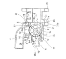
このロータ1を回転駆動する回転駆動装置3は、図4に示すように、モータ33と減速機34とからなるものである。
減速機34は、モータ33の回転軸に設けられた第1平歯車35、第1平歯車35に噛み合う第2平歯車36と同軸上に配置されて一体に回転するように設けられた第3平歯車37と、第3平歯車37に噛み合う第4平歯車39と、第4平歯車39と同軸上に配置されて一体に回転するように設けられた第5ねじ歯車40と、この第5ねじ歯車(ウォーム)40に噛み合う第6はす歯歯車(ウォームホイール)である出力歯車41を備えるものである。
As shown in FIG. 4, the
The
各歯車の噛み合い部分で、モータ33の回転が減速されるようになっている。また、第5ねじ歯車40と第6はす歯歯車である出力歯車41から構成されるウォームギヤでモータ33の回転が減速されるようになっている。
出力歯車41は、減速機34の歯車機構の中で最も径の大きな歯車であり、かつ、ロータ1に接続されてロータ1を一体に回転させる出力軸46が同軸上に固定されており、この出力軸46と一体に回転するようになっている。なお、図4において、出力軸46の基端部側が図示されており、ロータ1の回転軸11に接続される先端部は、図中、ボデー本体31の裏側からロータ1側に延出している。
The rotation of the
The
この出力歯車41には、出力歯車41の回転中心を中心とする円弧状の溝43が設けられている。また、回転駆動装置3のボデーの蓋32側には、その所定位置に円弧状の溝43内に挿入された状態の角度ストッパ44が設けられている。なお、図4においては、蓋32(図1に図示)が図示されておらず、蓋32の内側面から突出する部分を図示している。
The
また、出力歯車41の溝43の両端部は、出力歯車41を左右にそれぞれ回転させた場合に、角度ストッパ44が突き当てられる突き当て部47となっている。この角度ストッパ44と、両端に突き当て部47を有する出力歯車41の溝43が、減速機の弁体としてのロータ1に直接接続されてロータ1に動力を伝達する動力伝達要素(出力軸46)を除く動力伝達要素に設けられた規制手段になる。
Further, both end portions of the
また、角度ストッパ44は、半円より大きな円弧状の軸受部45と一体に蓋32に設けられている。この軸受部45は、出力歯車41の軸(出力軸46の外側の円筒部分)の蓋32側の端部を回転自在に支持している。なお、角度ストッパ44、軸受部45および蓋32は、一体に成形されたものであってもよい。
The
このような出力歯車41においては、出力歯車41が一方の方向に向けて回転した場合に(例えば、図中時計回りに回転した場合に)、円弧状の溝43の他方の突き当て部47に角度ストッパ44が接触するまで回転する。
In such an
同様に、出力歯車41が他方の方向に向けて回転した場合に(例えば、図中反時計回りに回転した場合に)、円弧状の溝43の一方の突き当て部47に、角度ストッパ44が接触するまで回転する。すなわち、この出力歯車41の円弧状の溝43のそれぞれの端部の突き当て部47に、角度ストッパ44が接触するまで回転する。
Similarly, when the
この規制手段による出力歯車41の回転角度範囲が規制されることにより、出力歯車41と一体に回転する出力軸46に接続されたロータ1の回転角度範囲が規制される。この実施形態では、出力歯車41とロータ1とは、出力軸46を介して一体に回転するようになっており、上述の規制手段により出力歯車41と同様にロータ1の回転角度が規制される。
By restricting the rotation angle range of the
このロータ1の回転角度の規制は、冷却水制御弁の作動時に、ロータ1の回転角度の移動範囲を規制するためのものではなく、例えば、冷却水制御弁の製造時や取付時、冷却水制御弁の作動開始前や作動開始時において、冷却水制御弁(回転駆動装置3)の制御において、例えば、ロータ1の回転に基づく冷却水制御弁の全閉位置と全開位置等の所定位置をイニシャライズ学習するためのものである。
The restriction of the rotation angle of the
なお、この例において、規制手段に規制されるロータ1の角度範囲は、例えば、上述のケーシング2側の二つの開口部25a、26aが全閉になる回転角度と、全開となる角度との間の範囲よりも少し広い角度範囲になっている。すなわち、例えば、出力歯車41が図中時計回り(または反時計回り)に回転して溝43の一方の端部の突き当て部47に角度ストッパ44が当接する前に例えば所定の全閉位置(または全開位置)となり、さらに、同じ方向に出力歯車41を回転して所定の全閉位置を少し超えた段階で溝43の一方の突き当て部47に角度ストッパ44が当接することになる。
In this example, the angle range of the
すなわち、溝43の両端それぞれ突き当て部47と、角度ストッパ44とにより規制される出力歯車41とロータ1の回転角度範囲の中心からの角度が、ロータ1の制御時に規制される角度より、所定角度だけ広くなっている。したがって、イニシャライズ学習時には、実際のロータ1の動作範囲となる回転角度の最小角度と最大角度とに対して、上述の規制手段において溝43の両端の突き当て部47が角度ストッパ44に接触する角度は、一方の突き当て部47に角度ストッパ44が突き当たる角度が最小角度より所定角度だけ小さい角度になり、他方の突き当て部47に角度ストッパ44が突き当たる角度が最大角度より所定角度だけ大きい角度になる。
That is, the angle from the center of the rotational angle range of the
例えば、冷却水制御弁の制御装置(制御手段)においては、エンジン始動時等にイニシャライズ処理を行う。この場合には、例えば、ロータ1を回転駆動装置3により回転させる。この際に、例えば、ロータ1を全閉側に回転させて角度ストッパ44を溝43の一方の端部の突き当て部47に接触させる。制御装置は、この接触位置となるモータ3の回転角度に対して予め設定された所定角度を加算した角度を例えば最小角度位置として記憶する。
For example, in the control device (control means) for the cooling water control valve, initialization processing is performed when the engine is started. In this case, for example, the
また、ロータ1を全閉側と反対となる全開側に回転させて角度ストッパ44を溝43の他方の端部の突き当て部47に接触させる。制御装置は、この接触位置となるモータ33の回転角度に対して予め設定された所定角度を減算した角度を例えば最大角度位置として記憶する。なお、上述の所定角度は、例えば、制御装置の記憶装置(例えば、フラッシュメモリやEPROM)に記憶されている。
Further, the
実際の制御では、記憶された最小角度位置から最大角度位置の範囲内で、ロータ1の回転角度が制御されるとともに、最小角度位置および/または最大角度位置を基準として、その間の回転角度が制御されることになる。したがって、冷却水制御弁の動作中は、出力歯車41の回転範囲が上述のようにイニシャライズ学習された最小角度位置と最大角度位置との間で動くように制御される。
また、基本的にイニシャライズ学習の際にだけ、角度ストッパ44が突き当て部47に当接することになり、通常の冷却水制御弁の動作時には、角度ストッパ44が突き当て部47に接触することがない。
In actual control, the rotation angle of the
Further, basically, the
このような冷却水制御弁にあっては、ロータ1の回転角度を回転駆動装置3を介して規制する規制手段としての出力歯車41の両端部に突き当て部47を有する溝43と角度ストッパ44により確定する実際の角度位置を用いてイニシャライズ学習をすることができる。これにより、正確なロータ1の回転角度位置の制御が可能になる。
In such a cooling water control valve, the
また、規制手段が、ロータ1の回転角度や、ロータ1に接続されてロータ1を直接回転駆動させる出力軸の回転角度を規制するのではなく、アクチュエータとしての回転駆動装置3内の減速機34の出力軸を除く動力伝達要素としての出力歯車41の回転角度を規制するようになっているので、ロータ1や出力軸の補強を必要とせず、ロータ1や出力軸の加工や組立に手間が増えるようなことがない。
Further, the restricting means does not restrict the rotation angle of the
なお、突き当てることにより回転を規制する構成、すなわち、回転規制時に応力が生じる構成を必ずしも強度や剛性の高くないロータ1や、径の小さな軸である出力軸に設けた場合に、ロータ1やケーシング2や出力軸の強化や、応力がかかる部分への高剛性部や高強度部の配置等の補強が必要になってしまい、小型化やコストダウンが困難になる。
In addition, when the structure that restricts rotation by abutting, that is, the structure that generates stress at the time of rotation restriction is provided on the
また、この実施形態では、規制手段を、減速機34の中でも最も径の大きな出力歯車41に設けているので、上述のように回転の規制時に応力が生じる構成であっても、補強の必要がなく、構成を簡素化できる。
Further, in this embodiment, since the restricting means is provided in the
また、この実施形態のように、冷却水制御弁本体側のケーシング2と回転駆動装置3のボデー本体31および蓋32が別体の場合に、回転駆動装置3で回転駆動されるロータ1を有する冷却水制御弁本体(冷却水制御弁の回転駆動装置3を除いた部分)側に規制手段を設けると、冷却水制御弁本体側と回転駆動装置3側との間に捻られる力が発生してしまうが、回転駆動装置3内に規制手段が設けられて、回転駆動装置3内で回転が規制されるので、冷却水制御弁本体側と回転駆動装置3側との間で捻られる力が生じることがなく、冷却水制御弁本体と回転駆動装置3との接合部を補強するなどの必要がない。したがって、冷却制御弁を簡素な構造にできる。
Further, as in this embodiment, when the
また、上述のように規制手段が、出力歯車41の歯の内側の本体部に設けられた円弧状の溝と回転駆動装置3のボデー(蓋32)側に固定された角度ストッパ44とからなり、略出力歯車41の配置範囲内のスペースに収めることが可能である。すなわち、規制手段を設けることにより、減速機34を大きくする必要がなく、小型化し易い構造にできる。
Further, as described above, the restricting means includes the arc-shaped groove provided in the main body inside the teeth of the
また、出力歯車41とロータ1とは、出力軸を介して一体に回転するので、出力歯車41の回転角度を規制することにより、ロータ1の回転角度を規制するようにしても、動力伝達による誤差が生じず、精度の高い制御を行うことができる。また、例えば、回転駆動装置3に制御装置を接続すれば、冷却水制御弁本体が回転駆動装置3に接続されていない状態でもイニシャライズ学習処理が可能になり、角度の測定も可能になる。
Further, since the
上述のようにモータ33を備える回転駆動装置3内に制御のイニシャライズ学習用に動作範囲を規制する規制手段が設けられており、ロータ1を有する冷却水制御弁本体を含まない回転駆動装置3内でモータ33の制御ために必要な構成が完結することになり、簡素な構造にできるとともに、冷却水制御弁を小型化し易い構造にすることができる。
As described above, the
1 ロータ(弁体)
2 ケーシング
3 回転駆動装置(アクチュエータ)
33 モータ
34 減速機
36 出力軸(弁体に直接接続される動力伝達要素)
41 出力歯車(動力伝達要素)
43 溝(規制手段)
44 角度ストッパ(規制手段)
47 突き当て部
1 Rotor (valve)
2
33
41 Output gear (power transmission element)
43 Groove (regulation means)
44 Angle stopper (regulation means)
47 Butting part
Claims (3)
前記弁体を収容するケーシングと、
前記弁体を駆動するアクチュエータと、
前記アクチュエータを制御する制御手段とを備え、
前記弁体の動作により、前記冷却水の流れを制御する冷却水制御弁であって、
前記制御手段は、前記弁体の動作範囲のイニシャライズ学習機能を有し、
前記アクチュエータは、モータと当該モータの回転を減速する減速機を備え、
前記減速機に備えられる動力伝達要素のうちの前記弁体に直接接続されて動力を伝達する前記動力伝達要素を除く少なくとも一つの前記動力伝達要素の動作範囲を規制することにより、前記弁体の動作範囲を規制し、かつ、前記制御手段によるイニシャライズ学習時に学習される前記弁体の動作範囲の特定に用いられる規制手段を備えることを特徴とする冷却水制御弁。 A valve body driven to control the flow rate of cooling water for cooling the engine;
A casing for housing the valve body;
An actuator for driving the valve body;
Control means for controlling the actuator,
A cooling water control valve for controlling the flow of the cooling water by the operation of the valve body,
The control means has an initialization learning function of the operating range of the valve body,
The actuator includes a motor and a speed reducer that decelerates the rotation of the motor.
By restricting the operating range of at least one of the power transmission elements except for the power transmission element that is directly connected to the valve body and transmits power among the power transmission elements provided in the speed reducer, A cooling water control valve characterized by comprising a regulating means for regulating the operating range and used for specifying the operating range of the valve body learned at the time of initialization learning by the control means.
前記規制手段に動作範囲を規制される前記伝達要素が、前記弁体を出力軸を介して回転させる出力歯車とされていることを特徴とする請求項1に記載の冷却水制御弁。 The actuator rotates the valve body;
The cooling water control valve according to claim 1, wherein the transmission element whose operating range is regulated by the regulating means is an output gear that rotates the valve body via an output shaft.
前記角度ストッパが前記溝の両端部のそれぞれに突き当たることで、前記出力歯車の回転角度範囲が規制されていることを特徴とする請求項2に記載の冷却水制御弁。 The restricting means is provided in the output gear, and includes an arc-shaped groove centered on the rotation center of the output gear, and an angle stopper inserted into the groove and fixed to the rotating output gear. Prepared,
The cooling water control valve according to claim 2, wherein a rotation angle range of the output gear is restricted by the angle stoppers abutting against both ends of the groove.
Priority Applications (8)
| Application Number | Priority Date | Filing Date | Title |
|---|---|---|---|
| JP2012126448A JP5925604B2 (en) | 2012-06-01 | 2012-06-01 | Cooling water control valve |
| PCT/JP2013/065236 WO2013180285A1 (en) | 2012-06-01 | 2013-05-31 | Coolant-control valve |
| MYPI2014703511A MY168481A (en) | 2012-06-01 | 2013-05-31 | Coolant-control valve |
| ES13796759.2T ES2664052T3 (en) | 2012-06-01 | 2013-05-31 | Coolant Control Valve |
| EP13796759.2A EP2857651B1 (en) | 2012-06-01 | 2013-05-31 | Coolant-control valve |
| IN10141DEN2014 IN2014DN10141A (en) | 2012-06-01 | 2013-05-31 | |
| CN201380027820.3A CN104411942B (en) | 2012-06-01 | 2013-05-31 | Cooling water control valve |
| US14/556,532 US9810136B2 (en) | 2012-06-01 | 2014-12-01 | Coolant-control valve |
Applications Claiming Priority (1)
| Application Number | Priority Date | Filing Date | Title |
|---|---|---|---|
| JP2012126448A JP5925604B2 (en) | 2012-06-01 | 2012-06-01 | Cooling water control valve |
Publications (2)
| Publication Number | Publication Date |
|---|---|
| JP2013249810A JP2013249810A (en) | 2013-12-12 |
| JP5925604B2 true JP5925604B2 (en) | 2016-05-25 |
Family
ID=49673468
Family Applications (1)
| Application Number | Title | Priority Date | Filing Date |
|---|---|---|---|
| JP2012126448A Active JP5925604B2 (en) | 2012-06-01 | 2012-06-01 | Cooling water control valve |
Country Status (8)
| Country | Link |
|---|---|
| US (1) | US9810136B2 (en) |
| EP (1) | EP2857651B1 (en) |
| JP (1) | JP5925604B2 (en) |
| CN (1) | CN104411942B (en) |
| ES (1) | ES2664052T3 (en) |
| IN (1) | IN2014DN10141A (en) |
| MY (1) | MY168481A (en) |
| WO (1) | WO2013180285A1 (en) |
Families Citing this family (20)
| Publication number | Priority date | Publication date | Assignee | Title |
|---|---|---|---|---|
| JP6050952B2 (en) * | 2012-05-15 | 2016-12-21 | 株式会社ミクニ | Cooling water control valve device |
| JP6394441B2 (en) * | 2014-04-07 | 2018-09-26 | 株式会社デンソー | Cooling device for internal combustion engine |
| JP6380073B2 (en) * | 2014-12-12 | 2018-08-29 | アイシン精機株式会社 | Refrigerant control valve device |
| JP6581367B2 (en) * | 2015-03-04 | 2019-09-25 | 日立オートモティブシステムズ株式会社 | Flow control valve |
| JP6409956B2 (en) | 2015-03-30 | 2018-10-24 | アイシン精機株式会社 | Refrigerant control valve device |
| JP6304105B2 (en) * | 2015-04-06 | 2018-04-04 | 株式会社デンソー | Control device for engine cooling system |
| KR101694043B1 (en) | 2015-07-30 | 2017-01-09 | 현대자동차주식회사 | Control method of intergrated flow control valve |
| JP2017096152A (en) | 2015-11-24 | 2017-06-01 | アイシン精機株式会社 | Cooling system of internal combustion engine |
| US20170241308A1 (en) * | 2016-02-24 | 2017-08-24 | Ford Global Technologies, Llc | Oil maintenance strategy for electrified vehicles |
| DE102016112235A1 (en) * | 2016-07-05 | 2018-01-11 | Dr. Ing. H.C. F. Porsche Aktiengesellschaft | Device for controlling the coolant flow in internal combustion engines |
| US10344883B2 (en) * | 2016-11-02 | 2019-07-09 | Schaeffler Technologies AG & Co. KG | Modular electro-mechanical rotary valve |
| JP6790802B2 (en) * | 2016-12-21 | 2020-11-25 | 株式会社デンソー | Flow control valve |
| JP7054644B2 (en) * | 2018-05-09 | 2022-04-14 | 株式会社キッツ | Opening / closing position setting structure of electric actuator for valve and its opening / closing position setting method |
| CN115289245A (en) | 2018-05-31 | 2022-11-04 | 株式会社电装 | Valve device |
| CN108979832A (en) * | 2018-07-13 | 2018-12-11 | 芜湖力锐德电子科技有限公司 | A kind of electric drive actuator |
| CN112204356A (en) * | 2018-07-13 | 2021-01-08 | 株式会社三国 | Detection device |
| JP7127558B2 (en) * | 2019-01-25 | 2022-08-30 | トヨタ自動車株式会社 | internal combustion engine cooling system |
| CN112648062B (en) * | 2019-10-10 | 2021-09-14 | 广州汽车集团股份有限公司 | Self-learning method of temperature control module for automobile |
| US11473695B2 (en) * | 2019-11-26 | 2022-10-18 | Takatori Seisakusho Co., Ltd. | Actuator |
| WO2021228780A1 (en) * | 2020-05-11 | 2021-11-18 | Rotiny Aps | Actuator for fluid flow controllers |
Family Cites Families (13)
| Publication number | Priority date | Publication date | Assignee | Title |
|---|---|---|---|---|
| JP3195687B2 (en) * | 1993-03-24 | 2001-08-06 | 太平洋工業株式会社 | Stopper mechanism of rotating machine |
| JP3794783B2 (en) * | 1997-05-16 | 2006-07-12 | 日本サーモスタット株式会社 | Cooling control device for internal combustion engine |
| JP2001099347A (en) * | 1999-09-30 | 2001-04-10 | Canon Precision Inc | Valve actuator unit control circuit device |
| JP2002098245A (en) * | 2000-09-21 | 2002-04-05 | Denso Corp | Flow control valve, and cooling system for internal combustion engine using the same |
| DE10053850A1 (en) * | 2000-10-30 | 2002-05-08 | Bosch Gmbh Robert | eccentric valve |
| US6659050B1 (en) * | 2002-03-06 | 2003-12-09 | Dana Corporation | Valve assembly for controlling coolant flow exiting an engine |
| JP3872743B2 (en) * | 2002-03-28 | 2007-01-24 | 株式会社日立製作所 | Throttle valve opening / closing device |
| JP4012449B2 (en) * | 2002-09-20 | 2007-11-21 | トヨタ自動車株式会社 | Cooling device for internal combustion engine |
| JP2005133624A (en) * | 2003-10-30 | 2005-05-26 | Hitachi Ltd | Electronic control throttle device |
| JP4146456B2 (en) | 2005-07-21 | 2008-09-10 | 三菱電機株式会社 | Engine cooling system controller |
| JP2007285173A (en) * | 2006-04-14 | 2007-11-01 | Denso Corp | Valve opening/closing control device |
| FR2901004B1 (en) * | 2006-05-12 | 2008-11-07 | Valeo Systemes Thermiques | CONTROL VALVE AND CIRCUIT COMPRISING SUCH VALVE |
| JP2011169390A (en) * | 2010-02-18 | 2011-09-01 | Mitsubishi Materials Cmi Corp | Four-way valve |
-
2012
- 2012-06-01 JP JP2012126448A patent/JP5925604B2/en active Active
-
2013
- 2013-05-31 ES ES13796759.2T patent/ES2664052T3/en active Active
- 2013-05-31 EP EP13796759.2A patent/EP2857651B1/en active Active
- 2013-05-31 WO PCT/JP2013/065236 patent/WO2013180285A1/en active Application Filing
- 2013-05-31 IN IN10141DEN2014 patent/IN2014DN10141A/en unknown
- 2013-05-31 MY MYPI2014703511A patent/MY168481A/en unknown
- 2013-05-31 CN CN201380027820.3A patent/CN104411942B/en active Active
-
2014
- 2014-12-01 US US14/556,532 patent/US9810136B2/en active Active
Also Published As
| Publication number | Publication date |
|---|---|
| MY168481A (en) | 2018-11-09 |
| ES2664052T3 (en) | 2018-04-18 |
| US20150083057A1 (en) | 2015-03-26 |
| CN104411942A (en) | 2015-03-11 |
| US9810136B2 (en) | 2017-11-07 |
| IN2014DN10141A (en) | 2015-08-21 |
| WO2013180285A1 (en) | 2013-12-05 |
| EP2857651B1 (en) | 2018-02-21 |
| EP2857651A4 (en) | 2016-04-20 |
| JP2013249810A (en) | 2013-12-12 |
| CN104411942B (en) | 2016-12-28 |
| EP2857651A1 (en) | 2015-04-08 |
Similar Documents
| Publication | Publication Date | Title |
|---|---|---|
| JP5925604B2 (en) | Cooling water control valve | |
| JP6846083B2 (en) | Valve and cooling water circulation system | |
| JP5889106B2 (en) | Rotary valve | |
| JP6501641B2 (en) | Flow control valve | |
| JP5914176B2 (en) | Rotary valve | |
| CN107614949B (en) | Flow control valve | |
| JP6254686B2 (en) | COOLING CONTROL DEVICE, FLOW CONTROL VALVE, AND COOLING CONTROL METHOD | |
| EP2857723B1 (en) | Rotary valve | |
| JP6254402B2 (en) | Flow control valve | |
| WO2016092936A1 (en) | Refrigerant control valve device | |
| JP7114890B2 (en) | Cooling water control valve device | |
| JP5955418B2 (en) | Mechanical coolant pump | |
| JP6581367B2 (en) | Flow control valve | |
| WO2019117151A1 (en) | Cooling water control valve device and engine cooling system using same | |
| JP6742489B2 (en) | valve | |
| JP7060657B2 (en) | Valve gears and automotive heat medium systems | |
| JP2018035779A (en) | Control device of engine cooling system | |
| JP2008309408A (en) | Damper device | |
| JP6784577B2 (en) | Control valve | |
| JP4059055B2 (en) | Cooling liquid injection method and flow control valve used for the injection method | |
| JP7260894B2 (en) | Electronic control throttle device for internal combustion engine | |
| WO2014069465A1 (en) | Exhaust gas shutoff control device | |
| JP2002295270A (en) | Throttle device for internal combustion engine |
Legal Events
| Date | Code | Title | Description |
|---|---|---|---|
| A621 | Written request for application examination |
Free format text: JAPANESE INTERMEDIATE CODE: A621 Effective date: 20150528 |
|
| TRDD | Decision of grant or rejection written | ||
| A01 | Written decision to grant a patent or to grant a registration (utility model) |
Free format text: JAPANESE INTERMEDIATE CODE: A01 Effective date: 20160412 |
|
| A61 | First payment of annual fees (during grant procedure) |
Free format text: JAPANESE INTERMEDIATE CODE: A61 Effective date: 20160420 |
|
| R150 | Certificate of patent or registration of utility model |
Ref document number: 5925604 Country of ref document: JP Free format text: JAPANESE INTERMEDIATE CODE: R150 |
|
| R250 | Receipt of annual fees |
Free format text: JAPANESE INTERMEDIATE CODE: R250 |
|
| R250 | Receipt of annual fees |
Free format text: JAPANESE INTERMEDIATE CODE: R250 |
|
| R250 | Receipt of annual fees |
Free format text: JAPANESE INTERMEDIATE CODE: R250 |
|
| R250 | Receipt of annual fees |
Free format text: JAPANESE INTERMEDIATE CODE: R250 |
|
| R250 | Receipt of annual fees |
Free format text: JAPANESE INTERMEDIATE CODE: R250 |