JP5922695B2 - 畦 coating machine - Google Patents
畦 coating machine Download PDFInfo
- Publication number
- JP5922695B2 JP5922695B2 JP2014078398A JP2014078398A JP5922695B2 JP 5922695 B2 JP5922695 B2 JP 5922695B2 JP 2014078398 A JP2014078398 A JP 2014078398A JP 2014078398 A JP2014078398 A JP 2014078398A JP 5922695 B2 JP5922695 B2 JP 5922695B2
- Authority
- JP
- Japan
- Prior art keywords
- trimming
- drum
- plates
- plate
- coater
- Prior art date
- Legal status (The legal status is an assumption and is not a legal conclusion. Google has not performed a legal analysis and makes no representation as to the accuracy of the status listed.)
- Expired - Lifetime
Links
Images


Landscapes
- Soil Working Implements (AREA)
Description
本発明は、土盛体により切削されて元畦箇所に供給された畦塗り用の泥土を、回転しながら元畦に塗りつけて、元畦を修復するドラム状の整畦体を改良した畦塗り機に関する。 The present invention is an improvement of a drum-shaped trimming body for repairing a maroon by applying the mud for dredging, which has been cut by a clay body and supplied to the marsh, to the marsh while rotating. Related to the machine.
従来、走行機体の後部に連結装置を介して着脱可能に連結される機枠と、この機枠に回転自在に設けられ、畦塗り用の泥土を切削して元畦箇所に供給する土盛体と、この土盛体の後方に位置して、前記土盛体により供給された泥土を回転しながら元畦に塗りつけて、元畦を修復するドラム状の整畦体(整畦ドラム)とを備えた畦塗り機が周知である。そして、整畦ドラムの泥土を回転しながら元畦に塗りつけ回転しながら畦の内側面を修復する側面修復体は、円錐状の円弧面または円錐状の多段平面を有している。 Conventionally, a machine frame that is detachably connected to the rear part of the traveling machine body via a connecting device, and a pile body that is rotatably provided on the machine frame and cuts mud for dredging and supplies it to the main fence location. And a drum-shaped trimming body (grinding drum) that is located behind the earthwork body and that is applied to the main fence while rotating the mud supplied by the earthwork body and repairs the former earth. The coater provided is well known. And the side surface restoration body which repairs the inner surface of a cage | basket | coat while applying and rotating on the main rod while rotating the mud of the trimming drum has a conical circular arc surface or a conical multistage plane.
上記従来の畦塗り機においては、整畦ドラムの側面修復体が円錐状の円弧面または円錐状の多段平面を有しており、しかも偏心回転しながら土盛体により供給された泥土を元畦に塗りつけて畦の内側面を修復するので、土盛体により切削されて元畦箇所に供給される泥土の状態によっては、所望の(十分な)元畦修復が行えない場合がある、という問題点があった。また、整畦ドラムは、円錐状の円弧面または円錐状の多段平面など有しているところから、その形状や製造上、作用等において改良すべき点があった。本発明は、上記の問題点を解決することを目的になされたものである。 In the above-described conventional dredging machine, the side restoration body of the trimming drum has a conical circular arc surface or a conical multi-stage plane, and the mud soil supplied by the embankment is rotated while being eccentrically rotated. The problem is that the desired (sufficient) repair of the main fence may not be possible depending on the state of the mud that is cut by the clay and supplied to the main fence location because the inner surface of the fence is repaired There was a point. Further, since the trimming drum has a conical circular arc surface or a conical multistage flat surface, there is a point to be improved in its shape, manufacturing, operation, and the like. The present invention has been made to solve the above problems.
上記の目的を達成するために本発明は、以下の構成を特徴としている。
A.走行機体の後部に連結装置を介して着脱可能に連結される機枠と、この機枠に回転自在に設けられ、畦塗り用の泥土を切削して元畦箇所に供給する土盛体と、この土盛体の後方に位置して、前記土盛体により供給された泥土を回転しながら元畦に塗りつけて、元畦を修復するドラム状の整畦体とを有する畦塗り機であって、前記整畦体は、回転しながら畦を形成する整畦ドラムを、回転中心から外周側に向けて複数の整畦板を周方向に等間隔に配設して形成し、各整畦板を相互に連結して各整畦板の境界部分に段差部を形成した。
In order to achieve the above object, the present invention is characterized by the following configurations.
A. A machine frame that is detachably connected to the rear part of the traveling machine body via a connecting device, and a pile body that is rotatably provided on the machine frame and that cuts the mud for paddy coating and supplies it to the main fence part, A drum coater having a drum-shaped trimming body for repairing the marshal, which is positioned behind the bank and is applied to the marshal while rotating the mud supplied by the mud The trimming body is formed by arranging a trimming drum that forms a collar while rotating by arranging a plurality of trimming plates at equal intervals in the circumferential direction from the rotation center toward the outer peripheral side. Were connected to each other to form a stepped portion at the boundary portion of each trimming plate.
B.上記整畦ドラムの隣接する整畦板は相互に所定の重なりを有し、その重なり部分に垂直段部を形成した。
C.上記複数の整畦板を、複数の連結部材により連結して整畦ドラムを形成した。
B. Adjacent trimming plates of the trimming drum had a predetermined overlap with each other, and a vertical step was formed in the overlapping portion.
C. The plurality of trimming plates are connected by a plurality of coupling members to form a trimming drum.
D.上記複数の連結部材を複数組のもので構成し、そのうちの少なくとも1組のものを整畦板に対し着脱可能とした。
E.上記複数組の連結部材のうちの少なくとも1組のものを、整畦板に対する固着位置を変更可能とした。
D. The plurality of connecting members are composed of a plurality of sets, and at least one of them is detachable from the trimming plate.
E. At least one set of the plurality of sets of connecting members can change the fixing position with respect to the trimming plate.
<作用>上記A.〜E.の構成により本発明の畦塗り機における整畦体(整畦ドラム)は、以下の作用を行う。
(1).回転しながら畦を形成する整畦ドラムは、回転中心から外周側に向けて複数の整畦板を周方向に等間隔に配設して形成し、各整畦板を相互に連結して各整畦板の境界部分に段差部を形成することで、整畦ドラムは土盛体により供給された泥土を、回転しながら各段差部により間欠的に叩打し、泥土を固めながら元畦に塗りつけ、従来の整畦ドラムに比べ良好な畦を形成する。
<Operation> ~ E. With the configuration described above, the trimming body (shaping drum) in the plastering machine of the present invention performs the following actions.
(1). The trimming drum that forms ridges while rotating is formed by arranging a plurality of grading plates at equal intervals in the circumferential direction from the rotation center toward the outer peripheral side, and connecting the respective grading plates to each other. By forming a step on the border of the trimming plate, the trimming drum intermittently taps the mud supplied by the earthwork with each stepping part while rotating, and smears the mud on the marshal as it hardens. As a result, a good wrinkle is formed as compared with the conventional straightening drum.
(2).整畦ドラムの隣接する整畦板は相互に所定の重なりを有し、その重なり部分に垂直段部を形成することで、土盛体により供給された泥土を、回転しながら各垂直段部により間欠的に叩打しながら泥土を固めて元畦に塗りつけ、良好な畦を形成でき、しかも整畦板の重なり部分により泥土が整畦ドラムの内面側に侵入するのを少なくする。
(3).複数の整畦板を、複数の連結部材により連結して整畦ドラムを形成することで、整畦ドラムの製造が簡単になる。
(2). Adjacent trimming plates of the trimming drum have a predetermined overlap with each other, and by forming a vertical step portion in the overlapping portion, the mud soil supplied by the pile body is rotated by each vertical step portion. The mud is solidified and applied to the main rod while being beaten intermittently to form a good rod, and the mud is less likely to enter the inner surface of the trimming drum due to the overlapping portion of the trim plates.
(3). By producing a straightening drum by connecting a plurality of straightening plates by a plurality of connecting members, the production of the straightening drum is simplified.
(4).複数の連結部材を複数組のもので構成し、そのうちの少なくとも1組のものを整畦板に対し着脱可能とすることで、整畦ドラムの製造が容易となると共に、整畦板が損傷した場合には、その部分の補修が容易に行える。
(5).複数組の連結部材のうちの少なくとも1組のものを、整畦板に対する固着位置を変更可能とすることで、整畦ドラムの製造が容易となり、整畦板が損傷した場合には補修が容易となる。
(4). A plurality of connecting members are composed of a plurality of sets, and by making at least one of them detachable from the trimming plate, it becomes easy to manufacture the trimming drum and the trimming plate is damaged. In some cases, the repair can be easily performed.
(5). By making it possible to change the fixing position of at least one of the plurality of sets of connecting members with respect to the trimming plate, it is easy to manufacture the trimming drum, and repair is easy when the trimming plate is damaged. It becomes.
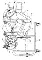
以下、本発明の実施の形態を添付の図面を参照して具体的に説明する。図1〜図3において、符号1は図示しないトラクタの後部に設けられたトップリンク及び左右一対のロアリンクにより昇降可能に連結され、トラクタのPTO軸から動力を受けて土盛体5及びドラム状の整畦体6を回転駆動し、圃場において土盛体5により畦塗り用の泥土を切削して元畦箇所に供給し、該土盛体5により供給された泥土を整畦体6により元畦に塗りつけて元畦を修復する整畦作業を行う畦塗り機である。この畦塗り機1は、前記トップリンク及びロアリンクに連結されるトップマスト2及びロアリンク連結部3を、機枠4から前方に突出させた左右一対のヒッチフレーム11に設け、土盛体5及びその後方に設けられる整畦体6は、機枠4により連結されて左右方向に配設されている。
Hereinafter, embodiments of the present invention will be specifically described with reference to the accompanying drawings. 1 to 3, reference numeral 1 denotes a top link provided at the rear of a tractor (not shown) and a pair of left and right lower links that can be moved up and down, receiving power from the PTO shaft of the tractor, and a
機枠4は、伝動ケースを兼ねており、土盛体5及び整畦体6に動力を伝達するように連結している。該機枠4の基端部は、左右一対の支持フレーム7に左右回動(昇降)可能に支持され、機枠4を介して土盛体5及び整畦体6を作業位置と非作業位置とに回動するようにしている。機枠4の先端部には、前方に向け土盛体5に動力伝達するための出力軸を内装した伝動ケース8を一体的に設けると共に、後方に向け整畦体6を駆動するための伝動ケース9及び減速機構を内装したデフケース10を一体的に設けている。
The
支持フレーム7は、その先端部に、水平方向の連結軸13を介して左右一対のヒッチフレーム11の基端部が上下回動可能に連結されて前方に向け延出されている。このヒッチフレーム11の両先端部に前記トップマスト2が取付けられ、トラクタに設けられたトップリンクに連結ピンを介して上下回動可能に枢支される。また、ヒッチフレーム11の両基端側に前記ロアリンク連結部3が取付けられ、トラクタに設けられた左右一対のロアリンクに連結ピンを介して上下回動可能に枢支される。そして、トラクタのロアリンクをロアリンク連結部3に連結して畦塗り機1を揚上させたとき、ヒッチフレーム11と機枠4の基端部との間の連結軸13を中心として機枠4、土盛体5、整畦ドラム6等は上下に回動可能となり、畦塗り機1を非作業位置に回動した状態で後述する作業部回動装置19によりトラクタの後部に接近するのを防止する。
The
上記ヒッチフレーム11,11間には、前後方向に入力軸12が軸支されている。この入力軸12の先端部には、トラクタのPTO軸から図示しないユニバーサルジョイント、伝動軸等を介して動力が伝達される。入力軸12の後方に位置する上記機枠4の基端部には、該基端部の垂直面内での回転中心となる回転軸14が前後方向に軸支され、この回転軸14の先端部と入力軸12の後端部との間を図示しないユニバーサルジョイントにより連結し、このユニバーサルジョイントの位置で上下回動可能となっている。回転軸14から動力が機枠4を通って伝動ケース8,9及びデフケース10に伝達され、土盛体5及び整畦体6をそれぞれ駆動する。
Between the
回転軸14には、入力軸12から回転軸14に伝達される回転動力を接,断するクラッチ(図示せず)が設けられている。このクラッチは、機枠4を介して土盛体5及び整畦体6を作業位置に回動したとき接続され、土盛体5及び整畦体6を非作業位置に回動したとき断たれるように作動する。また、このクラッチは、機枠4の基端部(回転軸14)を中心に土盛体5及び整畦体6を作業位置と非作業位置に回動させたとき、作業位置では動力が接続状態となり、非作業位置では動力が断たれる状態になるように、土盛体5、整畦体6を作業位置と非作業位置に回動させる回動動作と連動して自動的に切換えられる。
The rotating
土盛体5は、図示しないが、ロータリ軸(回転軸14)の軸周に複数本の切削爪と土寄せ板を放射方向に装着すると共に、上側をカバーにより覆い、元畦の一部及び圃場の土壌を切削して元畦に対して畦状に盛り上げる周知のロータリ切削装置からなるものである。また、整畦体6は、図4以下に示すが、その第1の実施例のものは図4(a)、(b)に示すように、偏心回転しながら畦の内側面を形成する整畦ドラム15の外周面に、回転中心から外周側に向けて、その回転方向に後退角を有して螺旋状に捻曲する複数(実施例では8枚)の整畦板15aを周方向に等間隔に形成し、各整畦板15aは、平面視でトロコイド曲線上の点が連続した曲面を有し、整畦ドラム15は、偏心回転しながら各整畦板15aを順に泥土に接して畦の内側面を形成するものである。各整畦板15aは大きさの異なる2枚の正方形状の連結部材15b,15cの各角部により相互(1枚置き)に溶接により連結して各整畦板15aの境界部分に段差部15dを形成し、整畦ドラム15の平面視外周縁を円形に形成している。上記2つの連結部材15b,15cのうち少なくとも連結部材15bは、整畦板15aに対して着脱可能の構成にしてもよいものである。
Although not shown in the figure, the
整畦ドラム15の回転中心には、元畦の上面を水平状に修復する円筒形状の上面修復体16が設けられ、この上面修復体16を中心に各整畦板15aが元畦の下方に向かって拡開し、元畦をテーパ状に修復するほぼ円錐形状の側面修復体を形成している。上面修復体16は、外側に向け延長部が取付け可能である。各整畦板15aは、回転軸(上面修復体16の回転中心)に対し傾斜した状態に固定され、また、各整畦板15aはそれぞれ上下に垂直段部を有して連結部材15b15cにより固着されている。各整畦板15aにより形成される側面修復体及び上面修復体16の上方は、カバーにより覆われている。
A cylindrical upper
上記土盛体5の上側には、土盛量調節装置17が設けられている。また、整畦ドラム15の上側には、機枠4を介して土盛体5及び整畦体6を作業位置と非作業位置とに回動する際に用いる回動用取っ手18が設けられている。前記ヒッチフレーム11と機枠4との間には、畦塗り機1を機枠4の基端部を中心に回動させて機枠4を介して土盛体5及び整畦体6を作業位置と非作業位置に回動させる際、その回動作動により土盛体5及び整畦体6の前後姿勢を調節可能とした回転ハンドル20を備えた作業部回動装置19が平面視で前後斜め方向に設けられている。機枠4には、接地輪(コールタ)21が上下調節装置21aを介して設けられている。
A deposit
そして、作業者が回動用取っ手18を持って左右方向に回動させることで、機枠4を介して土盛体5及び整畦体6が機枠4の基端部を中心に回動し、土盛体5及び整畦体6を非作業位置あるいは作業位置のいずれかに移動させる。上記機枠4の基端部の外周部には、土盛体5及び整畦体6を作業位置あるいは非作業位置に回動させたとき、それぞれの位置にロックする回動ロック装置4aが設けられている。
Then, when the operator holds the rotation handle 18 and rotates it in the left-right direction, the
ヒッチフレーム11と機枠4の先端部との間には、土盛体5及び整畦体6を機枠4の基端部を中心に回動させて、土盛体5及び整畦体6を作業位置あるいは非作業位置に移動させる際に、補助的働きをするガススプリング22が介装されている。このガススプリング22は、機枠4を介して土盛体5及び整畦体6を作業位置から非作業位置に、あるいは非作業位置から作業位置に回動させるとき、土盛体5及び整畦体6を持ち上げるときは軽い力で揚上でき、土盛体5及び整畦体6を下降させるときはその自重により急激に降下しないように弾発作用をする。畦塗り機1には、トラクタに着脱するとき、あるいは移動させたり、収納したりする際に用いるスタンド23が着脱可能に設けられている。
Between the
上記整畦ドラム15は、上記図4の第1実施例のように、回転中心の取付け基部に、平面視で内端側の幅が狭く、外端側の幅が次第に広くなる複数枚の整畦板15aの基端部を、隣接する整畦板15aが相互に所定の重なりを有するよう取付け、該整畦板15aの重なり部分に、図示しないが折返し部を設けて上下に固着し、前記重なり部分の隙間は内端側が狭く、外端側が広くなるよう、螺旋状の垂直段部を形成してもよいものである。
As shown in the first embodiment of FIG. 4, the trimming
図5(a)、(b)に示す第2実施例の整畦ドラム24は、図4の第1実施例の整畦ドラム15とは、上面修復体16の回転中心と偏心して外周側に向けて、その回転方向後側をわずかに突出させて直線状の後退角を有して複数(8枚)の整畦板24aを周方向に等間隔に配設し、外周縁を非円形に形成したほかは、整畦ドラム15と同様の構成を有している。即ち、整畦ドラム24は、平面視で回転中心から先端側に向けて内端側の幅が狭く、外端側の幅が次第に広くなる直線状の側縁を有する8枚の整畦板24aを、回転方向後側をわずかに突出させて平面視外周縁が非円形になるように設け、各整畦板24aは、隣接する整畦板24aが相互に所定の重なり部分24bを有するよう連結部材24c,24dにより固着している。そして、各整畦板24aの重なり部分24bに、垂直段部24eを形成したものである。
5A and 5B, the adjusting
図6に示す第3実施例の整畦ドラム25は、8枚の整畦板25aにより重なり部分25bを有して形成されるドラムの内側に、4本の固定杆25cを上面修復体16の回転中心を通って放射方向に延びるようにして配設し、各固定杆25cの両端部を、上面修復体16を挟んで対向する整畦板25a,25aにそれぞれ固着している。そして、各重なり部分25bの回転方向後端部分に段部25dを形成し、ドラムの外周縁は円形をなしている。図7に示す第4実施例の整畦ドラム26は、図4の第1実施例の連結部材15b,15cに代えてドラムの内側に8角形をなす1枚の個体板26bを設けて、この固定板26bの角部を各整畦板26aに固着し、上面修復体16のボス部に取付けている。そして、各整畦板26aの境界部分に螺旋状の垂直段部26cを形成している。
The trimming
さらに、図8(a)、(b)に示す第5実施例の整畦ドラム27は、図5の第2実施例における整畦ドラム24の連結部材24c,24dに代えて、整畦ドラム27のドラムの内側において、各整畦板27aの重なり部分27bに沿って設けた2つの連結片27c,27cにより固着している。そして、各整畦板27aの境界部分に直線状の垂直段部27dを形成したものである。また、図9に示す第6実施例の整畦ドラム28は、図4の第1実施例の連結部材15b,15cに相当する連結部材28b,28dのうちの連結部材28bに、整畦板28aへの固着位置(角部)に着脱可能の取付け部28cを設けている。そして、取付け部28cにより固着された整畦板28aが損傷して、交換したり、補修したりする場合に取付け部28cを着脱するようにしている。また、この取付け部28cは整畦板に対する固着位置を変更可能であり、任意の整畦板28aに固着できる。
Further, the straightening
このような構成の畦塗り機1においては、トラクタの後部のトップリンクにトップマスト2を、ロアリンクにロアリンク連結部3をそれぞれ連結して、3点リンクにより昇降可能に連結する。トラクタのPTO軸からユニバーサルジョイント、伝動軸を介して入力軸12に動力が伝達される。畦塗り機1が整畦作業を行うときは、土盛体5及び整畦体6を、機枠4の基端部を中心に回動させて非作業位置から作業位置に移動させる。この回動動作は、まずロック装置4aのロックを解除し、作業者が回動用取っ手18を持って回動することにより行われる。このとき、ガススプリング22は、土盛体5、整畦体6を軽く持ち上げ、急激に降下しないように弾発作用する。土盛体5、整畦体6が作業位置に達すると回動ロック装置4aは自動的にロックされる。
In the plastering machine 1 having such a configuration, the top mast 2 is connected to the top link at the rear of the tractor, and the lower link connecting portion 3 is connected to the lower link, so that the three links can be moved up and down. Power is transmitted from the PTO shaft of the tractor to the
土盛体5、整畦体6が作業状態に回動する動作と連動して回転軸14のクラッチが自動的に接続状態となる。そして、入力軸12に受けた動力は、ユニバーサルジョイントを介して回転軸14に伝達され、回転軸14から機枠4を通って伝動ケース8,9及びデフケース10に伝達され、土盛体5及び整畦体6をそれぞれ駆動する。そして、トラクタ2の走行と共に、土盛体5及び整畦体6により整畦作業が行われる。土盛体5及び整畦体6の作用深さを調節するときは、トラクタのロアリンクにより畦塗り機1の支持高さを変えることによって行うことができるが、基本的には接地輪21を上下調節装置21aにより上下移動調節することにより行われる。また、回転ハンドル20により作業部回動装置19の前後長さを調節することにより、トラクタに対する畦塗り機1の前後作業姿勢を調節する。
The clutch of the
土盛体5では切削爪と土寄せ板により元畦の一部及び圃場の土壌を切削して元畦側に対して畦状に盛り上げ、その盛り上げた土壌を整畦体6の整畦ドラム15(あるいは24,25,26,27,28のいずれか)の整畦面が偏心回転して畦法面を叩いて目的とする畦に成形する。また、水平円筒体16により整畦ドラムによって成形された畦の頂部を平らに成形する。
In the
畦塗り機1が作業を行わずにトラクタに連結されて路上走行するときは、土盛体5及び整畦体6を、回動用取っ手18により機枠4の基端部を中心に回動させて非作業位置に移動させる。この回動動作は、まずロック装置4aのロックを解除し、作業者が回動用取っ手18を持って上方へ回転することにより行われる。このとき、ガススプリング22は、土盛体5、整畦体6を軽い力で持ち上げて回動し、急激に降下しないように弾発作用する。土盛体5、整畦体6が非作業位置に達すると、回動ロック装置4aにより自動的にロックされ、回転軸14のクラッチが自動的に断状態となる。
When the hull coater 1 is connected to the tractor and travels on the road without performing work, the
<効果>
以上説明したように本発明の畦塗り機の整畦ドラムによれば、請求項1〜5の構成により以下の作用効果を奏することができる。
<Effect>
As described above, according to the trimming drum of the plastering machine of the present invention, the following effects can be achieved by the configurations of claims 1 to 5.
(1).整畦体は、回転しながら畦を形成する整畦ドラムを、回転中心から外周側に向けて複数の整畦板を周方向に等間隔に配設して形成し、各整畦板を相互に連結して各整畦板の境界部分に段差部を形成したので、整畦ドラムは土盛体により供給された泥土を、回転しながら各段差部により間欠的に叩打し、泥土を固めながら元畦に塗りつけ、従来の整畦ドラムに比べ良好な畦を形成することができる。特に、土盛体により供給される泥土の土質が悪い場合や含水率が適当でない場合でも、良好な畦を形成することができる。 (1). The trimming body is formed of a trimming drum that forms a collar while rotating, with a plurality of trimming plates arranged at equal intervals in the circumferential direction from the center of rotation toward the outer circumferential side. Since the stepped part is formed at the boundary part of each trimming plate, the sanding drum is intermittently beaten by each stepped part while rotating, and the mudstone is solidified. It can be applied to the main bar to form a better bar than the conventional adjusting drum. In particular, even when the soil quality of the mud supplied by the embankment is poor or when the moisture content is not appropriate, good dredging can be formed.
(2).整畦ドラムの隣接する整畦板は相互に所定の重なりを有し、その重なり部分に垂直段部を形成したので、土盛体により供給された泥土を、回転しながら各垂直段部により間欠的に叩打しながら泥土を固めて元畦に塗りつけ、良好な畦を形成することができる。しかも整畦板の重なり部分により泥土が整畦ドラムの内面側に侵入するのを少なくすることができる。 (2). Adjacent trimming plates of the trimming drum have a predetermined overlap with each other, and a vertical step portion is formed in the overlapping portion. Therefore, the mud soil supplied by the embankment is intermittently rotated by each vertical step portion. It is possible to form a good cocoon by solidifying the mud and applying it to the cocoon while hitting it. In addition, it is possible to reduce the intrusion of mud into the inner surface of the trimming drum due to the overlapping portion of the trimming plates.
(3).複数の整畦板を、複数の連結部材により連結して整畦ドラムを形成したので、複雑な形状の整畦ドラムであっても容易に製造することができる。
(4).複数の連結部材を複数組のもので構成し、そのうちの少なくとも1組のものを整畦板に対し着脱可能としたので、複雑な形状の整畦ドラムの製造が容易となると共に、整畦板が損傷した場合には、その部分の補修や交換を容易に行うことができる。
(3). Since a plurality of trimming plates are connected by a plurality of connecting members to form a trimming drum, even a complex-shaped trimming drum can be easily manufactured.
(4). Since the plurality of connecting members are composed of a plurality of sets, and at least one of them is detachable from the trimming plate, it is easy to manufacture a trimming drum having a complicated shape, and the trimming plate In the case of damage, the part can be easily repaired or replaced.
(5).複数組の連結部材のうちの少なくとも1組のものを、整畦板に対する固着位置を変更可能としたので、複雑な形状の整畦ドラムでも製造が容易となり、整畦板が損傷した場合に、整畦板の補修や交換を容易に行うことができる。 (5). Since the fixing position of at least one of the plurality of connecting members can be changed with respect to the trimming plate, it is easy to manufacture even with a complex-shaped trimming drum, and when the trimming plate is damaged, Repair and replacement of the sizing plate can be easily performed.
1 畦塗り機
2 トップマスト
3 ロアリンク連結部
4 機枠
4a ロック装置
5 土盛体
6 整畦体
7 支持フレーム
8,9 伝動ケース
10 デフケース
11 ヒッチフレーム
12 入力軸
13 連結軸
14 回転軸
15 第1実施例の整畦ドラム
15a 整畦板
15b,15c 連結部材
15d 段差部
16 上面修復体
17 土盛量調節装置
18 回動用取っ手
19 作業部回動装置
20 回転ハンドル
21 接地輪(コールタ)
21a 上下調節装置
22 ガススプリング
23 スタンド
24 第2実施例の整畦ドラム
24a 整畦板
24b 重なり部分
24c,24d 連結部材
24e 垂直段部
25 第3実施例の整畦ドラム
25a 整畦板
25b 重なり部分
25c 固定杆
25d 段部
26 第4実施例の整畦ドラム
26a 整畦板
26b 個体板
26c 垂直段部
27 第5実施例の整畦ドラム
27a 整畦板
27b 重なり部分
27c,27c 連結片
27d 垂直段部
28 第6実施例の整畦ドラム
28b,28d 連結部材
28c 取付け部
DESCRIPTION OF SYMBOLS 1 Coat coating machine 2 Top mast 3 Lower
21a
Claims (4)
前記土盛体の後方に位置して、前記土盛体により供給された泥土を畦に塗りつけて、畦を修復する整畦体と、
を有する畦塗り機であって、
前記土盛体及び前記整畦体の作用深さは、当該畦塗り機が備える接地輪と該接地輪の上下移動を調節する上下調節装置と作業部回動装置とによって調節され、
前記整畦体は、
上面修復体と、
複数の整畦板と、
連結部材とを有し、
前記上面修復体は、前記整畦体の回転軸に設けられ、
前記複数の整畦板は、同方向に配設され、
隣接する前記整畦板同士は、前記整畦板の各境界部に沿って設けられた前記連結部材で連結され、
隣接する前記整畦板の間に段差部が形成される
ことを特徴とする畦塗り機。 A clay body that cuts mud and supplies it to the dredger,
Located on the rear side of the earthen body, smearing the mud supplied by the earthen body to the fence,
A wrinkle coater having
The working depths of the earthen body and the trimming body are adjusted by a grounding wheel provided in the basket coater, a vertical adjustment device that adjusts the vertical movement of the grounding wheel, and a working unit rotation device,
The trimming body is:
Top surface restoration body ,
And Seiaze plate number of the multiple,
A connecting member,
The top surface repair material is provided on the rotary shaft of the front KiSeiaze body,
The plurality of trimming plates are arranged in the same direction,
The adjacent trimming plates are connected by the connecting member provided along each boundary portion of the trimming plate,
A wrinkle coater characterized in that a step portion is formed between the adjacent trimming plates.
ことを特徴とする請求項1に記載の畦塗り機。 The wrinkle coater according to claim 1, wherein the connecting member is fixed to at least an outer peripheral edge portion of the trimming plate.
ことを特徴とする請求項1に記載の畦塗り機。 The wrinkle coater according to claim 1, wherein the connecting member has a curved surface.
ことを特徴とする請求項1に記載の畦塗り機。 The connection member is fixed so that a boundary portion that protrudes toward the adjustment surface side at the boundary portion of the adjacent alignment plates protrudes from the connection member. The coater as described.
Priority Applications (1)
| Application Number | Priority Date | Filing Date | Title |
|---|---|---|---|
| JP2014078398A JP5922695B2 (en) | 2014-04-07 | 2014-04-07 | 畦 coating machine |
Applications Claiming Priority (1)
| Application Number | Priority Date | Filing Date | Title |
|---|---|---|---|
| JP2014078398A JP5922695B2 (en) | 2014-04-07 | 2014-04-07 | 畦 coating machine |
Related Parent Applications (1)
| Application Number | Title | Priority Date | Filing Date |
|---|---|---|---|
| JP2012025233A Division JP5587922B2 (en) | 2012-02-08 | 2012-02-08 | 畦 coating machine |
Publications (3)
| Publication Number | Publication Date |
|---|---|
| JP2014128288A JP2014128288A (en) | 2014-07-10 |
| JP2014128288A5 JP2014128288A5 (en) | 2014-09-18 |
| JP5922695B2 true JP5922695B2 (en) | 2016-05-24 |
Family
ID=51407343
Family Applications (1)
| Application Number | Title | Priority Date | Filing Date |
|---|---|---|---|
| JP2014078398A Expired - Lifetime JP5922695B2 (en) | 2014-04-07 | 2014-04-07 | 畦 coating machine |
Country Status (1)
| Country | Link |
|---|---|
| JP (1) | JP5922695B2 (en) |
Cited By (1)
| Publication number | Priority date | Publication date | Assignee | Title |
|---|---|---|---|---|
| JP2016135149A (en) * | 2016-04-28 | 2016-07-28 | 小橋工業株式会社 | Levee plastering machine |
Families Citing this family (1)
| Publication number | Priority date | Publication date | Assignee | Title |
|---|---|---|---|---|
| JP6095190B1 (en) * | 2016-10-04 | 2017-03-15 | 松山株式会社 | 畦 coating machine |
Family Cites Families (11)
| Publication number | Priority date | Publication date | Assignee | Title |
|---|---|---|---|---|
| JP3165637B2 (en) * | 1996-03-06 | 2001-05-14 | 松山株式会社 | Row coating machine |
| JP3250963B2 (en) * | 1996-10-14 | 2002-01-28 | 小橋工業株式会社 | Hitch device for farm work machine |
| JP3148678B2 (en) * | 1997-04-08 | 2001-03-19 | 株式会社ササキコーポレーション | Row forming machine |
| JP3108387B2 (en) * | 1997-05-28 | 2000-11-13 | 松山株式会社 | Row coating machine |
| JP3378510B2 (en) * | 1998-09-17 | 2003-02-17 | 松山株式会社 | Row coating machine |
| JP4174745B2 (en) * | 1999-05-31 | 2008-11-05 | 株式会社富士トレーラー製作所 | Straightener |
| JP3868672B2 (en) * | 1999-07-21 | 2007-01-17 | 小橋工業株式会社 | 畦 coating machine |
| JP2001263896A (en) * | 2000-03-16 | 2001-09-26 | Sanyo Electric Co Ltd | Refrigerator |
| JP3252138B2 (en) * | 2000-10-23 | 2002-01-28 | 松山株式会社 | Row coating machine |
| JP3704300B2 (en) * | 2001-08-31 | 2005-10-12 | 松山株式会社 | 畦 coating machine |
| JP5706569B2 (en) * | 2014-08-19 | 2015-04-22 | 小橋工業株式会社 | 畦 coating machine |
-
2014
- 2014-04-07 JP JP2014078398A patent/JP5922695B2/en not_active Expired - Lifetime
Cited By (1)
| Publication number | Priority date | Publication date | Assignee | Title |
|---|---|---|---|---|
| JP2016135149A (en) * | 2016-04-28 | 2016-07-28 | 小橋工業株式会社 | Levee plastering machine |
Also Published As
| Publication number | Publication date |
|---|---|
| JP2014128288A (en) | 2014-07-10 |
Similar Documents
| Publication | Publication Date | Title |
|---|---|---|
| US10704224B1 (en) | Grading device for skid steer equipment | |
| JP5922695B2 (en) | 畦 coating machine | |
| JP5706569B2 (en) | 畦 coating machine | |
| JP5587922B2 (en) | 畦 coating machine | |
| JP6067174B1 (en) | 畦 coating machine | |
| JP6084321B2 (en) | 畦 coating machine | |
| JP6153553B2 (en) | 畦 coating machine | |
| JP5989704B2 (en) | 畦 coating machine | |
| JP2014128287A (en) | Levee-plastering machine | |
| JP5000051B2 (en) | 畦 coating machine | |
| US6662480B1 (en) | Bucket level | |
| JP2014209926A (en) | Levee plastering machine | |
| JP2008206423A (en) | Levee-plastering machine | |
| JP4542169B2 (en) | 畦 coating machine | |
| JP2009131196A (en) | Levee coater | |
| JP4838943B2 (en) | Arrangement body | |
| JP4541608B2 (en) | 畦 coating machine | |
| JP4866094B2 (en) | Agricultural machine | |
| JP4795894B2 (en) | Agricultural machine | |
| JP2006166768A (en) | Offset working implement | |
| JP4318964B2 (en) | Offset work machine | |
| JP2008154595A (en) | Levee-plastering machine | |
| JP5073388B2 (en) | 畦 coating machine | |
| US11447927B2 (en) | Support assembly for a grading machine | |
| JPH09322606A (en) | Levee plastering machine |
Legal Events
| Date | Code | Title | Description |
|---|---|---|---|
| A521 | Written amendment |
Free format text: JAPANESE INTERMEDIATE CODE: A523 Effective date: 20140521 |
|
| A621 | Written request for application examination |
Free format text: JAPANESE INTERMEDIATE CODE: A621 Effective date: 20140502 |
|
| A521 | Written amendment |
Free format text: JAPANESE INTERMEDIATE CODE: A523 Effective date: 20140801 |
|
| RD03 | Notification of appointment of power of attorney |
Free format text: JAPANESE INTERMEDIATE CODE: A7423 Effective date: 20141029 |
|
| RD04 | Notification of resignation of power of attorney |
Free format text: JAPANESE INTERMEDIATE CODE: A7424 Effective date: 20141029 |
|
| A977 | Report on retrieval |
Free format text: JAPANESE INTERMEDIATE CODE: A971007 Effective date: 20150209 |
|
| A131 | Notification of reasons for refusal |
Free format text: JAPANESE INTERMEDIATE CODE: A131 Effective date: 20150217 |
|
| A521 | Written amendment |
Free format text: JAPANESE INTERMEDIATE CODE: A523 Effective date: 20150420 |
|
| A131 | Notification of reasons for refusal |
Free format text: JAPANESE INTERMEDIATE CODE: A131 Effective date: 20150929 |
|
| A521 | Written amendment |
Free format text: JAPANESE INTERMEDIATE CODE: A523 Effective date: 20151130 |
|
| TRDD | Decision of grant or rejection written | ||
| A01 | Written decision to grant a patent or to grant a registration (utility model) |
Free format text: JAPANESE INTERMEDIATE CODE: A01 Effective date: 20160412 |
|
| A61 | First payment of annual fees (during grant procedure) |
Free format text: JAPANESE INTERMEDIATE CODE: A61 Effective date: 20160414 |
|
| R150 | Certificate of patent or registration of utility model |
Ref document number: 5922695 Country of ref document: JP Free format text: JAPANESE INTERMEDIATE CODE: R150 |
|
| R250 | Receipt of annual fees |
Free format text: JAPANESE INTERMEDIATE CODE: R250 |
|
| EXPY | Cancellation because of completion of term |