JP5922591B2 - Packaged propellant air-induced variable thrust rocket engine - Google Patents
Packaged propellant air-induced variable thrust rocket engine Download PDFInfo
- Publication number
- JP5922591B2 JP5922591B2 JP2012555119A JP2012555119A JP5922591B2 JP 5922591 B2 JP5922591 B2 JP 5922591B2 JP 2012555119 A JP2012555119 A JP 2012555119A JP 2012555119 A JP2012555119 A JP 2012555119A JP 5922591 B2 JP5922591 B2 JP 5922591B2
- Authority
- JP
- Japan
- Prior art keywords
- combustion chamber
- air
- air flow
- rocket engine
- fuel
- Prior art date
- Legal status (The legal status is an assumption and is not a legal conclusion. Google has not performed a legal analysis and makes no representation as to the accuracy of the status listed.)
- Active
Links
Images


Classifications
-
- F—MECHANICAL ENGINEERING; LIGHTING; HEATING; WEAPONS; BLASTING
- F02—COMBUSTION ENGINES; HOT-GAS OR COMBUSTION-PRODUCT ENGINE PLANTS
- F02K—JET-PROPULSION PLANTS
- F02K9/00—Rocket-engine plants, i.e. plants carrying both fuel and oxidant therefor; Control thereof
- F02K9/42—Rocket-engine plants, i.e. plants carrying both fuel and oxidant therefor; Control thereof using liquid or gaseous propellants
- F02K9/60—Constructional parts; Details not otherwise provided for
- F02K9/62—Combustion or thrust chambers
Landscapes
- Engineering & Computer Science (AREA)
- Chemical & Material Sciences (AREA)
- Combustion & Propulsion (AREA)
- Mechanical Engineering (AREA)
- General Engineering & Computer Science (AREA)
- Toys (AREA)
- Testing Of Engines (AREA)
- Fuel-Injection Apparatus (AREA)
- Fluidized-Bed Combustion And Resonant Combustion (AREA)
- Structures Of Non-Positive Displacement Pumps (AREA)
- Pressure Welding/Diffusion-Bonding (AREA)
Description
本出願は、2010年2月24日に出願した仮特許出願第61/338816号に関し、米国特許法第119条(e)に基づいてこの先願出願の優先権を主張する。また、この仮特許出願は、参照により本特許出願に組み込まれる。 This application relates to provisional patent application No. 61/338816, filed on Feb. 24, 2010, and claims the priority of this earlier application under section 119 (e) of the US Patent Act. This provisional patent application is also incorporated into this patent application by reference.
本発明は、空気誘導可変推力ロケット・エンジンに関する。 The present invention relates to an air induced variable thrust rocket engine.
ライト兄弟は最初の動力飛行の成功者と言われているが、古代人の夢および野心でさえ、地面から飛び立ち、重力に逆らうという思いに魅了されていた。本出願人は、鳥の観察から想像するに、論理からすれば古代にも空を飛ぶという着想が存在したであろう。古代人に欠けていたのは、推進の源であり、十分に強力で、かつ、軽い材料であった。また、空気が平らな表面上を横向きに通過する着想も、鳥、葉および重い平らな物体を地面から持ち上げる風の観察から明らかだったであろう。 The Wright brothers are said to have been successful in their first power flight, but even ancient dreams and ambitions were fascinated by the desire to fly off the ground and resist gravity. The applicant, if imagined from bird observations, would have had the idea of flying in the sky in antiquity. What the ancients lacked was a source of propulsion, a sufficiently powerful and light material. Also, the idea of air passing sideways over a flat surface would have been apparent from observations of the wind lifting birds, leaves and heavy flat objects from the ground.
レオナルド・ダ・ビンチの時代から、飛行機械の人の範例には、空気を移動させ、かつ、圧縮するためのファン・ブレードを末端に備えたシャフトなどの質量の動力駆動回転が含まれていた。質量を回転させることにより、機体を頑丈にする必要があり、延いては機体をより重くする必要があるトルクおよび応力荷重が生成される。 Since the days of Leonardo da Vinci, the paradigm of flying machines has included mass-powered rotations such as shafts with fan blades at the ends to move and compress air . Rotating the mass creates torque and stress loads that require the airframe to be rugged and therefore heavier.
今日の航空機およびミサイル推進の一般的な方法は、プロペラ、ガス・タービン(ジェット・エンジン)ロケット、ラム・ジェットおよびスクラム・ジェットである。プロペラ駆動航空機は、揮発性液体航空燃料を使用して往復機関またはガス・タービン・エンジンにエネルギーを供給し、これらの往復機関またはガス・タービン・エンジンはプロペラを駆動し、あるいはヘリコプタの場合であればロータを駆動する。プロペラまたはロータは、その直径全体にわたって十分な空気を引き込み、翼に対して十分な速度の空気を介して航空機を押しつけ、それにより揚力を提供し、あるいはヘリコプタの場合であればロータに対して十分な速度の空気を介してヘリコプタを押しつけ、それにより垂直に持ち上げるための下向きの推力を提供する。これらの従来のタイプの推進は、重くて騒音が多く、複雑で、高価であり、また、可動部品が非常に多く、そのために機械的に故障し易い。また、振動およびトルクは、これらのトルクおよび振動の力によって生成される応力を処理するためのより頑丈な機体、延いてはより重い機体に対する要求事項のため、航空機の設計にとっては重要な考察事項である。エンジン自体でさえ高い精度の部品が必要であり、また、トルクおよび荷重のため、構造には、強く、かつ、重い金属が必要である。 Common methods of aircraft and missile propulsion today are propellers, gas turbine (jet engine) rockets, ram jets and scram jets. Propeller-driven aircraft use volatile liquid aviation fuel to supply energy to reciprocating engines or gas turbine engines, which drive propellers or are helicopters. Drive the rotor. A propeller or rotor draws enough air across its diameter and pushes the aircraft through air at a sufficient speed against the wing, thereby providing lift, or in the case of a helicopter enough for the rotor The helicopter is pushed through the air at a high speed, thereby providing a downward thrust to lift vertically. These conventional types of propulsion are heavy, noisy, complex and expensive, and have a large number of moving parts and are therefore prone to mechanical failure. Also, vibration and torque are important considerations for aircraft design because of the requirements for more robust and heavier airframes to handle the stresses generated by these torques and vibration forces. It is. Even the engine itself requires highly accurate parts, and because of torque and load, the structure requires strong and heavy metals.
往復機関の場合、適切な比率の空気および液体燃料が一組の機械式弁を介して閉じたシリンダ内に誘導される。この混合物は、クランク軸に接続されたピストンによって圧縮される。ピストンがその行程の頂部に到達すると、ピストンより上方の燃焼室に火花が生成され、圧縮された燃料空気混合物が点火され、それによりピストンが下に向かって強制されてクランク軸が回転する。このタイプの機関のクランク軸は歯車箱に接続されており、この歯車箱を介して、この歯車箱からトルクが得られ、ギヤー・アップまたはギヤー・ダウンされた後、プロペラ・システムまたはロータ・システムに引き渡される。歯車箱、軸および応力がかかる他の部材は、それらにトルク荷重がかかるため、硬化鋼で構築しなければならず、これが重量の問題をさらに深刻にしている。これらのタイプの機関は、重量、振動、着氷問題、ダスト・チョーキング、熱効率の悪さおよび維持費に起因する欠点を抱えており、これらが航空機の寿命に対して占める割合は、飛行時間1に対して維持時間3の割合である。 In the case of a reciprocating engine, an appropriate ratio of air and liquid fuel is directed through a set of mechanical valves into a closed cylinder. This mixture is compressed by a piston connected to the crankshaft. When the piston reaches the top of its stroke, a spark is generated in the combustion chamber above the piston, igniting the compressed fuel-air mixture, thereby forcing the piston downward and rotating the crankshaft. The crankshaft of this type of engine is connected to a gearbox, through which torque is obtained from the gearbox, and after being geared up or down, the propeller system or rotor system To be handed over. Gearboxes, shafts and other components that are stressed must be constructed of hardened steel because they are torque loaded, which makes the weight problem even more serious. These types of engines have drawbacks due to weight, vibration, icing problems, dust choking, poor thermal efficiency and maintenance costs, which account for 1 flight time in aircraft life. It is a ratio of the maintenance time 3 to the ratio.
既存のジェット・エンジンは、それらの液体燃料を使用して、重く、かつ、コストのかかる精密タービン・ホイールを介して空気を加熱し、かつ、膨張させている。このタービン・ホイールは30,000RPMで回転し、縦軸と一致している、エンジンの吸込み口まで延在しているシャフトを駆動している。極めて精密で、高価で、かつ、壊れ易い多段圧縮機ブレードがこのシャフトに取り付けられており、タービン・ホイールに空気を提供するために角度が付けられている。これらのエンジンは、著しい燃焼速度で燃料を連続的に燃焼させ、この燃料の多くが加熱のために浪費され、また、一度始動すると、火炎の輪を維持しなければならないため、流入するジェット燃料に点火するために連続的に運転しなければならない。タービンおよび部分的に燃焼したJP5の質量流のひゅーひゅーという音は、極めて大きい騒音を発生し、また、莫大な熱特徴を残す。また、ジェットおよびタービン・エンジンも、出力が変化している間、フレームアウトを生じることがあり、したがって出力の変化を遅くしなければならず、これは、質量が回転するエンジンのもう一つの欠点である。 Existing jet engines use these liquid fuels to heat and expand the air through heavy and costly precision turbine wheels. The turbine wheel rotates at 30,000 RPM and drives a shaft that extends to the engine inlet, which is coincident with the longitudinal axis. A very precise, expensive and fragile multistage compressor blade is attached to this shaft and angled to provide air to the turbine wheel. These engines burn the fuel continuously at a significant burn rate, much of this fuel is wasted for heating, and once started, the flame ring must be maintained, so the incoming jet fuel Must continually drive to ignite. The noise of the turbine and partially burned JP5 mass flow generates very loud noise and leaves enormous thermal features. Jet and turbine engines can also produce flameouts while the output is changing, and therefore the change in output must be slowed, which is another disadvantage of a rotating engine. It is.
ジェットおよびタービン・エンジンは、正しくそれらの性質により、厳格な公差、壊れ易いタービン・ブレードおよびそれらが回転する速度のため、異物損傷(FOD)に対して極めて故障し易い。極めて微小な物体であっても、ジェット・エンジンに取り込まれると極めて重大な問題になる可能性があり、粉塵、火山灰、鳥およびあらゆる種類の瓦礫が航空機の着陸および離陸時に取り込まれる可能性がある。これは、とりわけ作戦地帯、つまり急ごしらえで準備された飛行場で真実であり、取り込まれた微小物体が重大な損傷、故障の原因になり、さらには爆発の原因になることさえある。ジェットおよびタービン・エンジンにおける重量および回転する質量によって生じる力のため、航空機を頑丈にしなければならず、したがって重く、かつ、剛直にしなければならない。また、製造費および維持費もジェット・エンジンのもう一つの欠点である。これらのタイプのエンジンの正面面積は、航空機に対して形状抵抗をもたらしており、また、大きなレーダ有効反射断面積をもたらしている。
固体燃料ロケット Jet and turbine engines, due to their nature correctly, are very prone to failure due to foreign object damage (FOD) due to tight tolerances, fragile turbine blades and the speed at which they rotate. Even very small objects can be a very serious problem when taken into a jet engine, and dust, volcanic ash, birds, and all sorts of debris can be taken in during aircraft landing and takeoff . This is especially true in operational zones, or airfields that are prepared in a hurry, where captured micro objects can cause serious damage, failure, and even explosion. Because of the forces generated by the weight and rotating mass in jet and turbine engines, the aircraft must be sturdy and therefore heavy and rigid. Manufacturing and maintenance costs are another drawback of jet engines. The front area of these types of engines provides shape resistance to the aircraft and also provides a large radar effective reflection cross section.
Solid fuel rocket
従来のロケットは、本質的には、ドラバル管またはベンチュリで知られている精密で、かつ、同心拘束の管である。この管すなわちロケット・エンジンには、爆発の寸前で燃焼する揮発性高エネルギー燃料が充填される。ロケットは、燃料および酸化剤の総質量をオン・ボードで運ばなければならない。一旦着火すると、燃焼停止は存在しない。燃料は、しばしば有毒であり、また、その取扱いおよび製造が危険である。また、これらのエンジンは、その構築が極めて複雑で、かつ、高価である。また、これらのエンジンの構築には、エキゾチック材料および厳格な公差が必要である。 Conventional rockets are essentially precision and concentric constraining tubes known as Doraval tubes or venturis. This tube or rocket engine is filled with volatile high energy fuel that burns just before the explosion. The rocket must carry the total mass of fuel and oxidant on board. Once ignited, there is no combustion stop. Fuels are often toxic and dangerous to handle and manufacture. In addition, these engines are extremely complicated to construct and expensive. The construction of these engines also requires exotic materials and tight tolerances.
ロケットの漏れは、Challengerの爆発から分かるように重大な結果を招く。固体燃料ロケットは、本質的には、爆発寸前の制御された速度で燃焼する巨大な爆発性の棒である。流入する空気などの混合物の変化は、すべて、ロケット・エンジンが爆発する原因になり得る。爆発は、燃焼速度がその材料の音速を超えると生じる。酸素が豊富な大気を通り抜けて人が移動する場合、固体燃料ロケットのための酸化剤をオン・ボードで運ぶことは、場合によっては極めて危険である。これらのタイプのロケットは、騒音が極めて大きく、また、打上げに際しては職員を退避させなければならない。
液体燃料ロケット Rocket leaks have serious consequences as can be seen from the Challenger explosion. A solid fuel rocket is essentially a huge explosive rod that burns at a controlled rate on the verge of explosion. Any change in the mixture, such as the incoming air, can cause the rocket engine to explode. An explosion occurs when the burning rate exceeds the speed of sound of the material. When people move through an oxygen-rich atmosphere, it is sometimes extremely dangerous to carry an oxidizer for a solid fuel rocket on board. These types of rockets are extremely noisy, and personnel must be evacuated for launch.
Liquid fuel rocket
Robert H Goddardは、1926年に、液体燃料を搭載したロケットを最初に打ち上げた人であると言われている。また、ペルー人のPedro Pauletも、19世紀に液体ロケットの実験を導いたのは、パリで学生であった自分であると主張している。液体燃料を搭載したロケットは、燃料および酸化剤を個別のタンクで運び、しがたって燃料および酸化剤を燃焼室で混合するためのポンプおよび引渡しラインが必要である。液体ロケットは、必要な質量をタンク、ポンプおよび噴射器などに閉じ込めるためのそれらのエネルギー密度のため、望ましい。 Robert H Goddard is said to be the first person to launch a liquid-fueled rocket in 1926. Peruvian Pedro Paulet also claims that it was himself who was a student in Paris that led the liquid rocket experiment in the 19th century. A rocket loaded with liquid fuel requires a pump and a delivery line to carry the fuel and oxidant in separate tanks and thus mix the fuel and oxidant in the combustion chamber. Liquid rockets are desirable because of their energy density to confine the necessary mass in tanks, pumps, injectors, and the like.
液体ロケットの場合、燃料および酸化剤は、配管ラインを介して、従来のポンプまたはターボ・ポンプによって閉込めタンクから燃焼室に引き渡される。これらのポンプのいくつかは、うず状に回転させ、遠心力によって混合することによって燃料および酸化剤を混合する。他の混合方法は、緊密な流れの中で成分を衝突させ、それによりそれらを霧状にして、点火がより容易で、かつ、より完全に燃焼する混合物にするために、ノズルを収斂させることである。 In the case of a liquid rocket, fuel and oxidant are delivered from the containment tank to the combustion chamber by a conventional pump or turbo pump via a piping line. Some of these pumps mix fuel and oxidant by rotating in a vortex and mixing by centrifugal force. Another method of mixing is to converge the nozzles in order to make the components collide in a tight stream, thereby atomizing them into a mixture that is easier to ignite and burns more completely. It is.
液体ロケットには多くの欠点があり、タンク、ポンプ、噴射器および引渡しラインは、空の場合にタンク内に生成される真空のため、タンクを破壊する可能性のある極低温にさらされる。これは、タンク内の液体の運動、および重量を重くする着氷による推進体の潜在的不安定性と共に、液体ロケットを理想推進システムから程遠いものにしている。広く使用されている燃料および酸化剤の組合せである酸素および水素の貯蔵温度である−253度Cに露出されるポンプおよび噴射器は、推力から出力を奪い、また、重量を重くし、かつ、複雑性を増すことになる熱ガス循環システムによって加熱しなければならない。 Liquid rockets have many drawbacks, and tanks, pumps, injectors and delivery lines are exposed to cryogenic temperatures that can destroy the tank due to the vacuum created in the tank when empty. This makes the liquid rocket far from the ideal propulsion system, along with the liquid motion in the tank and the potential instability of the propellant due to heavy icing. Pumps and injectors exposed to -253 degrees C, the storage temperature of oxygen and hydrogen, a widely used fuel and oxidizer combination, take power out of thrust, increase weight, and It must be heated by a hot gas circulation system that adds complexity.
液体ロケットのための点火方法は、完全に安全ではない。ハード・スタートが一般的であり、瓦礫を何メートルにもわたって高速で吹き飛ばして、職員および財産に対して致命的な危険をもたらすことになる爆発の原因になっている。この状態は、正確な時間に、正確な強度で点火システムが燃料混合物への点火に失敗した場合に、突如として生じる。燃料混合物が燃焼室に蓄積し、そこで点火器が最終的に点火すると爆発が生じる。この爆発は、燃料混合物の豊富さの程度、およびハウジングの爆風圧定格に応じて、破片を何メートルにもわたって高速で吹き飛ばすことができる。このような爆発は、タンクを破壊し、燃料空気爆発の可能性をもたらすことになる。 The ignition method for liquid rockets is not completely safe. Hard start is common, causing blasts to blow away rubble at high speeds, causing fatal danger to personnel and property. This condition suddenly occurs when the ignition system fails to ignite the fuel mixture at the correct time and with the correct intensity. An explosion occurs when the fuel mixture accumulates in the combustion chamber where the igniter eventually ignites. This explosion can blow off debris at high speeds over many meters, depending on the extent of the fuel mixture abundance and the blast pressure rating of the housing. Such an explosion will destroy the tank and lead to the possibility of a fuel-air explosion.
最も使用されている点火方法には、点火プラグ、熱ブリッジ線からなどの炎があり、また、多くの他の同様の手段も使用される。これらのエンジンは、固体燃料ロケットとは異なり、弁で調節することができる。成分の複雑性および危険性の性質のため、単元推進薬が最も使用されている。いくつかの可能混合の揮発性は、信頼性の高い点火源の必要性を至上にしており、推進薬の多くの他の混合は、信頼性が高く、かつ、持続可能な点火源があれば可能である。 The most used ignition methods include flames such as spark plugs, from thermal bridge wires, and many other similar means are also used. These engines can be regulated by valves, unlike solid fuel rockets. Monopropellants are most often used because of the complexity and risky nature of the ingredients. The volatility of some possible blends has led to the need for a reliable ignition source, and many other blends of propellants have a reliable and sustainable ignition source Is possible.
スクラム・ジェットおよびラム・ジェットは、それぞれ独自の複数の問題を抱えた他のタイプの推進システムである。これらのタイプのエンジンは、ゼロ対気速度で運転することはできず、また、燃料が加えられる際の背圧を防止するためには、エンジンを上空にもたらすか、あるいは十分な空気流が存在する前に他の動力源を有し、約350mphまで推進させなければならない。ラム・ジェットは、空気の速度を減速させ、燃焼に先立って亜音速速度まで空気を圧縮するが、スクラム・ジェットは、それらの全運転範囲を通して超音速空気流で動作する。このタイプのエンジンには、燃料の燃焼時間などの多くのハイテク問題が存在しており、燃焼時間が遅すぎると、完全に燃焼する前に一掃されてしまう。現時点においては未だにその解決法が存在していないと思われる他の重大な問題は、空気の滑らかな流れを遮断し、燃料分布を撹乱し、かつ、制御不能の温度を生成する超音波衝撃波である。超音速出力飛行時間が制限されているのは、この温度の問題のために他ならない。
この出願の発明に関連する先行技術文献情報としては、以下のものがある(国際出願日以降国際段階で引用された文献及び他国に国内移行した際に引用された文献を含む)。
(先行技術文献)
(特許文献)
(特許文献1) 米国特許第3357191号明細書
(特許文献2) 米国特許第7506500号明細書
(特許文献3) 米国特許第7278611号明細書
(特許文献4) 米国特許第4901526号明細書
Scrum jets and ram jets are other types of propulsion systems that each have their own problems. These types of engines cannot be operated at zero airspeed, and to prevent back pressure when fuel is added, either bring the engine up or there is sufficient airflow It must have another power source and be propelled to about 350 mph before doing so. Ram jets reduce the speed of air and compress air to subsonic speeds prior to combustion, while scram jets operate with supersonic airflow throughout their entire operating range. This type of engine has many high-tech problems such as fuel combustion time, and if the combustion time is too slow, it will be wiped out before it burns completely. Another serious problem that currently seems to have no solution yet is ultrasonic shock waves that block the smooth flow of air, disturb the fuel distribution, and generate uncontrollable temperatures. is there. It is this temperature problem that limits the supersonic power flight time.
Prior art document information related to the invention of this application includes the following (including documents cited in the international phase after the international filing date and documents cited when entering the country in other countries).
(Prior art documents)
(Patent Literature)
(Patent Document 1) US Pat. No. 3,357,191 (Patent Document 2) US Pat. No. 7,506,500 (Patent Document 3) US Pat. No. 7,278,611 (Patent Document 4) US Pat. No. 4,901,526
本発明は、本発明に対する極めて多くの使用法および用途を有するパッケージ化推進薬空気誘導可変推力ロケット・エンジンである。ここで説明されているデバイスの主な目的は、航空機を推進させるための、軽量で、トルクおよび振動がない推力発生器を提供することである。このデバイスは、これらの力が小さいため、極めて軽量の航空機の製造を容易にすることができる。また、このデバイスは、高速空気流およびまたは結果として得られる推力を必要とするどこででも使用することができる。 The present invention is a packaged propellant air induced variable thrust rocket engine having numerous uses and applications for the present invention. The primary purpose of the device described herein is to provide a lightweight, torque and vibration free thrust generator for propelling an aircraft. This device can facilitate the manufacture of extremely lightweight aircraft because of these small forces. The device can also be used anywhere that requires high-speed airflow and / or resultant thrust.
本発明には、流入した空気を、酸化可能燃料の混合物の離散パケットからの熱エネルギーおよび運動エネルギーの短い継続期間のバーストによって加熱し、かつ、加速する前に、この流入する空気を圧縮し、かつ、加速する空力原理が使用されている。加熱され、かつ、加速された空気は、次に、デバイスを通って移動する際に膨張して推力を提供する。エネルギーの間欠バーストを開始する能力は、本発明の核心である。この能力は、透明な小さいエンクロージャ内に、全くの燃料源または他の燃料のための点火源のいずれかとしてナノ・サイズのアルミニウム粒子を使用することによって達成することができる。透明なプラスチックを透過する高強度光によってナノメートル・サイズの粒子に点火する能力は、著しい利点である。この効果は、大きさが光の波長より小さい粒子によってもたらされる。 The present invention heats the incoming air with short duration bursts of thermal and kinetic energy from discrete packets of the oxidizable fuel mixture and compresses the incoming air before accelerating, And the aerodynamic principle of acceleration is used. The heated and accelerated air then expands to provide thrust as it moves through the device. The ability to initiate intermittent bursts of energy is the heart of the present invention. This capability can be achieved by using nano-sized aluminum particles as either a whole fuel source or an ignition source for other fuels in a transparent small enclosure. The ability to ignite nanometer-sized particles with high-intensity light that passes through transparent plastics is a significant advantage. This effect is brought about by particles whose size is smaller than the wavelength of light.
光のエネルギーは、粒子によって吸収され、粒子から再放射することはできないため、粒子は、その融点を超えて極めて急速に加熱される。粒子が融解すると、その酸化した外部表面にひびが入り、酸化していないアルミニウムが露出する。水などの化合物中の酸素であれ、あるいは空気中の酸素であれ、酸素に対するアルミニウムの強い親和力によって直ちに酸化が生じ、かつ、熱が生成される。アルミニウムは最も高いエネルギー・レベルを提供するが、他のナノメートル・サイズの金属も同様の特性を提供する。 Since the energy of light is absorbed by the particle and cannot be re-emitted from the particle, the particle is heated very rapidly above its melting point. As the particles melt, the oxidized outer surface cracks, exposing the unoxidized aluminum. Whether it is oxygen in a compound such as water or oxygen in the air, the strong affinity of aluminum for oxygen immediately causes oxidation and generates heat. Aluminum provides the highest energy levels, but other nanometer sized metals provide similar properties.
ナノメートル・サイズのアルミニウム粒子は優れた放熱を提供するが、他の燃料およびまたはより大きいアルミニウム粒子を開始するそれらの能力により、より低コストの熱源が多くの用途に提供される。これらの場合、適切なレベルの光エネルギーによって遠隔で開始されるその能力は、依然としてその独自の利点を提供する。本発明は、エネルギーが、機械圧縮機を妨害する逆流を必要とすることなく、流入する空気に対する最大の熱伝達を可能にするパルス方式で、もっぱら所望の方向の推力で導かれるようにこれらのパケットを開始する。 Nanometer-sized aluminum particles provide excellent heat dissipation, but their ability to initiate other fuels and / or larger aluminum particles provides a lower cost heat source for many applications. In these cases, its ability to be initiated remotely by an appropriate level of light energy still provides its own advantages. The present invention is a pulsed system that allows maximum heat transfer to the incoming air without the need for backflow that interferes with the mechanical compressor, so that these are directed exclusively with the thrust in the desired direction. Start a packet.
高エネルギー燃料パケットは、ファン、プロペラ、圧縮機または前方対気速度の支援を必要とすることなく空気流を得ることができる位置および方法で点火される。本発明には、吸気エンジンにエネルギーを供給するために高エネルギー燃料パケットが利用されている。これらの高エネルギー燃料パケットは、水中でケースに入れられ、透明な外部ケーシングで覆われている。高エネルギー燃料パケットの中味には、ナノメートル・サイズのアルミニウム粒子、酸素源および任意選択で他の酸化可能物質が含まれている。高エネルギー燃料パケットは、ストロボまたはレーザなどの高強度トリガ光源からの光エネルギーによって点火され、あるいは燃焼室のこれらのアルミニウム粒子に作用する他の手段によって点火される。 The high energy fuel packet is ignited in a location and manner that allows air flow without the need for fans, propellers, compressors or forward airspeed assistance. The present invention utilizes a high energy fuel packet to supply energy to the intake engine. These high energy fuel packets are encased in water and covered with a transparent outer casing. The contents of the high energy fuel packet contain nanometer sized aluminum particles, an oxygen source, and optionally other oxidizable materials. The high energy fuel packet is ignited by light energy from a high intensity trigger light source, such as a strobe or laser, or by other means acting on these aluminum particles in the combustion chamber.
この燃焼により、燃焼室からおびただしい熱および熱蒸気放出が生成され、それにより臨界角がつけられたベンチュリ燃焼流領域を介して空気の速度が速くなる。パケットに燃料が分配され、また、指令によって燃料に点火することができるため、エンジンを瞬時オン・オフ動作、言い換えるとパルス動作させることができる。間欠着火のため、燃料の熱エネルギーをより完全に使用することができ、また、連続燃焼プロセスよりはるかに冷たい排気が可能になる。また、巡航時には、最大出力時とは異なる燃料混合を使用することも可能であり、それにより効率を高くすることができる。 This combustion generates a great deal of heat and thermal vapor emissions from the combustion chamber, thereby increasing the velocity of the air through the venturi combustion flow region with a critical angle. Since the fuel is distributed to the packets and the fuel can be ignited by a command, the engine can be instantaneously turned on / off, in other words, pulsed. Due to the intermittent ignition, the thermal energy of the fuel can be used more completely, and exhaust that is much colder than the continuous combustion process is possible. Also, during cruising, it is possible to use a fuel mixture different from that at maximum output, thereby increasing efficiency.
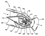
図1は、本発明の教示を使用した空気誘導ロケット・エンジン100を示したものである。空気は、前方空気流入口106から流入し、支持支柱135によって空気流ハウジング105内に支持されている中央空気分割器115によって分割される。中央空気分割器115の内側には、高エネルギー燃料パケット(EFP)117貯蔵隔室130が配置されている。この貯蔵隔室は、図には示されていないが、ハウジング105の外側に配置された、接続引渡し管を備えた別個の蓄積領域に置き換えることができ、あるいはこの別個の蓄積領域で補足することができる。 FIG. 1 shows an air-guided
推力が必要である場合、逆流防止弁140が開き、EFP117が空気/燃料引渡しマニホルド109を介して燃焼室120に噴射される。燃焼室120に存在している間に、ストロボ・ライト116または他の手段からの光エネルギーによって、水中およびEFP117に含まれているナノ・アルミニウム粒子が点火される。ナノ高エネルギー粒子によって極めて高い温度が生成され、それにより周囲の水が過熱蒸気に変換され、EFP117中の他の可燃性物質に同じく点火する。 When thrust is required, the
EFP117中には、酸化のためのより多くの酸素を提供するために一定の割合の過酸化水素を含むことができる。また、水も、燃焼室120に耐火材料を必要とするレベルに至るまでの温度上昇を防止する。温度上昇が制御された短い継続期間の燃焼を有することにより、より多くの熱エネルギーが、燃焼室120の壁を加熱するために浪費される代わりに、空気流を加速するために伝達される。この生成された高温蒸気は、燃焼室120から高速でベンチュリ燃焼流領域110に向かって指向的に膨張する。
この膨張により、空気流ハウジング105のベンチュリ燃焼流領域110の空気の温度が上昇し、密度が低下し、また、ベンチュリ燃焼流領域110を通って後方へ流れる。この後方流は、蒸気と加熱された空気の混合の速度によって生じる。圧力衝撃が散逸すると、空気洗浄弁142により、空気が分割器115上のより高い圧力領域から空気/燃料引渡しマニホルド106へ、空気入口通路145を通って流れ、また、取り付けられている燃焼室120によって残留熱がベンチュリ燃焼流領域110へ伝達され、それにより次のEFP117点火のための新鮮な空気が提供される。 This expansion increases the temperature of the air in the venturi
流入する、より密度および圧力が高く、より冷たい空気が、ベンチュリ燃焼流領域110を介した混合物の高速運動によって生成される低圧体積を充填する。膨張する蒸気は、その密度が空気より若干低いため、ベンチュリ燃焼流領域110へ膨張する際に、通路内の空気に熱を引き渡し、したがって空気のエンタルピーが大きくなる。このプロセスで、加熱が生じる際に空気の相対湿度が高くなって、より大きいエンタルピーが生成され、また、より希薄な空気蒸気混合物が生成され、この希薄な空気蒸気混合物は、その密度が低下する際に膨張してより速い速度を生成することになる。この熱伝達方法は、従来のタービンにおける空気の加熱および乾燥より有効である。 Incoming, denser and pressured, cooler air fills the low pressure volume generated by the high velocity motion of the mixture through the venturi
加湿された空気蒸気混合物は、それが膨張し、かつ、後部排気108へ向かって後方へ移動している間、より低い出口温度を有しており、この湿った空気蒸気混合物は、次に、流入する、より冷たく、かつ、より稠密な空気に置き換えられて環状流領域107に流入する。利用可能なすべての熱が伝達されると、他のEFP117が蓄積領域130から燃焼室120へ移動してサイクルが継続する。EFP117が分配され、かつ、点火される速さによって、デバイスの気流速度、質量流量および推力が決まる。 The humidified air vapor mixture has a lower outlet temperature while it expands and travels backward toward the
燃焼室120の指向性および設計、ならびにベンチュリ燃焼流領域110に対するその位置は、たとえ流入する空気の速度がゼロであっても、高圧熱蒸気フロントが環状流領域107に背圧を生成するのを防止している。空気蒸気混合物は、その速度および低密度のため、速やかに移動することにより、環状流領域107の両端間の圧力が降下する。この圧力降下により、空気ハウジング105内の前方入口106から後部排気108へ、ベンチュリ燃焼流領域110を通って空気が流れる。 The directivity and design of the combustion chamber 120, and its position relative to the venturi
空気の速度は、燃焼室120へのEFP117のエネルギーの投入によって膨張する熱フロントの温度および速度の関数である。これらの速度は、2k/sすなわち垂直飛行または水平飛行のための十分な推力を提供する速度より速い速度に達することがある。加湿され、かつ、加熱された空気は、姿勢制御ロケットからの排気に先立って、ベンチュリ燃焼流領域110を通って移動し、後部膨張ノズル108を通って後方へ向かって膨張する。 The air velocity is a function of the temperature and velocity of the thermal front that expands with the input of
特定の用途では、このデバイス100または複数のデバイス100を外部空気ハウジングによって覆うことができ、この外部空気ハウジングを介して空気が引き込まれ、姿勢制御ロケットの外部熱によって加熱され、かつ、より速い速度で排気されて余分の推力を提供する。より冷たい空気のこの流れは、姿勢制御ロケットを冷却し、熱特徴を小さくするか、あるいは除去することができる。設計の意図は、重量が軽い材料を使用することができるよう、エンジン内部の高い燃焼温度およびガス温度を回避することである。この設計意図は、燃料を直接水に接触させることによって容易に達成することができ、それにより姿勢制御ロケットを通って流れる空気に燃料エネルギーを伝達するための蒸気ならびに他の排気成分が生成される。 In certain applications, the
EFP117は、デバイスが要求に応じてさらに可変推力を提供することができるよう、様々な量の高エネルギーナノアルミニウム燃料および他の燃料を有することができる。このタイプのエンジンは、その連続熱特徴および音響が小さいため、戦闘状況下では恐らく最も望ましいエンジンであると思われ、これらの連続熱特徴および音響は、減衰させ、あるいは除去することが可能である。巡航出力レベルでは、間欠動作によって排気を大気状態に近づけることができる。この姿勢制御ロケットは回転質量を有していないため、小型兵器または砲弾破片による多くの貫通に耐え、運転を継続することができる。 The
極めて大きいスラスト・パワーを必要とする垂直離陸の状況では、水によって提供される温度制御により、必要なレベルの燃料を十分な水と共に追加し、かつ、蒸気を発火させてより大きい推力を提供し、それにより空気ハウジング105を介して追加空気を引き込み、余分の揚力を提供することができる。この姿勢制御ロケットの空気流中には可動部品は存在せず、EFP117を引き渡すための機構が存在しているだけである。ナノメートル・サイズのアルミニウムを使用して他の燃料の燃焼を開始することにより、液体燃料を使用している他の手段に優る多くの利点が提供される。 In vertical take-off situations that require extremely high thrust power, the temperature control provided by the water adds the required level of fuel with enough water and ignites the steam to provide greater thrust. , Thereby drawing additional air through the
これらのパケットは、高強度光または他の非接触手段を使用して点火することができる。ナノ・アルミニウムは、ガソリンなどの液体燃料と比較すると、46%より多いエネルギーを有しており、しかもその体積は、重量で3分の1にすぎない。このデバイスの場合、パッケージ化された形態で燃料を分配することにより、パルス動作が可能になる。戦闘地帯では、このパルス動作により、航空機は、敵に聞こえない滑空モードで静かに襲撃することができ、また、必要な場合にのみ出力を追加する能力を有することができる。さらに、設計により音響エネルギーが、排気空気の加速を促進し、かつ、移動軸に沿って航空機の背後に集中され、したがって航空機の前方に音はほとんど飛び出さない。 These packets can be ignited using high intensity light or other non-contact means. Nano-aluminum has more than 46% energy compared to liquid fuels such as gasoline, and its volume is only one third by weight. In the case of this device, pulsing is possible by distributing the fuel in a packaged form. In the battle zone, this pulse action allows the aircraft to silently attack in a gliding mode inaudible to the enemy and have the ability to add power only when needed. In addition, the design facilitates the acceleration of exhaust air and concentrates behind the aircraft along the axis of movement, so that little sound jumps out in front of the aircraft.
また、音は、騒音特徴が数十マイル先まで聞こえる現代の航空機エンジンと比較すると、間欠的に、低周波数で生成される。燃料パケット中のすべての材料には、燃焼プロセスで消費されることになるエネルギーが含まれており、また、その抽出されるエネルギーは、目に見える特徴または熱特徴を残さない。ナノAlパッケージは、このデバイスまたは他のデバイスにエネルギーを供給するための従来の燃料と組み合わせて点火源として使用することができる。開始と開始の間のタイミングは、先行する燃焼のすべての熱を使用するために十分に長くしなければならず、また、ベンチュリ燃焼流領域110への空気流は、安定した空気圧を確立するための時間を有していなければならない。 Sound is also generated intermittently at low frequencies compared to modern aircraft engines where noise characteristics can be heard tens of miles away. All materials in the fuel packet contain energy that will be consumed in the combustion process, and the extracted energy does not leave any visible or thermal features. The nano-Al package can be used as an ignition source in combination with conventional fuels for supplying energy to this or other devices. The timing between the start must be long enough to use all the heat of the preceding combustion, and the air flow to the venturi
この方法によれば、ベンチュリ燃焼流領域110で入口圧が降下する連続燃焼状態の場合に生じるような環状流領域107への空気の引き込みに対してではなく、空気を後方に推進するためにすべてのエネルギーが使用される。理想的には姿勢制御ロケットは、離陸または操縦などの最大出力インターバルを除き、最も有効に運転することができるようにサイズ化される。これらの高出力期間の間、この設計は、燃焼室120の設計のため、極めて大きい推力を出力することができる。燃焼室120への空気の独力補給を可能にするために着火と着火の間の時間間隔が不十分である用途の場合、任意選択の空気圧縮機148を追加して空気管145内の空気流を強化することができる。 According to this method, all to propel the air backwards, not against the entrainment of air into the annular flow region 107 as occurs in the case of a continuous combustion state where the inlet pressure drops in the venturi
また、このデバイスは、高速空気流を必要とするどこにでも使用することができる。これは非制限であり、火炎の吹き消し、走路の清掃、地球の掘削、ぬかるみまたは池の干上げ、埋設対象の発見、群衆制御、離陸ブースタ・エンジン、等々を含むことができる。このデバイスは、散らかったごみの吹き払いや、地雷および他の対象の掘り出しのために遠隔操作車両上で使用することができる。このデバイスは、吸込み口にシャッタを備え、また、質量交換流体として蒸気が使用されている場合、大気圏外で使用することができる。宇宙船の乗組員からの廃水を使用することができる場合であっても、真空の空間ではごく少量の水が必要である。この特定のスパイク設計は、図2に示されている自由流設計より速やかな空気の加速を有しているが、最大推力は自由流設計より小さい。 The device can also be used wherever high velocity airflow is required. This is unrestricted and may include flame blowing, runway cleaning, earth excavation, muddy or pond drying, discovery of buried objects, crowd control, take-off booster engine, and so on. This device can be used on remotely operated vehicles for trash blasting and mining and other object mining. This device is equipped with a shutter at the inlet and can be used outside the atmosphere if steam is used as the mass exchange fluid. Even if the wastewater from the spacecraft crew can be used, very little water is needed in the vacuum space. This particular spike design has a faster air acceleration than the free flow design shown in FIG. 2, but the maximum thrust is smaller than the free flow design.
図2は、メイン・フロー空気ハウジング205の入口201に空気が流入し、かつ、圧縮を生じることなく、デバイスを通って、燃焼器取付けリング208の周囲に配列された燃焼室240のクラスタを通り越して移動する際に、より有効に熱を伝達するために、非加熱期間の間、容易流を提供するベンチュリ燃焼流領域デバイス200を備えた高空気流修正ロケットである。これらの燃焼室240には、ディスペンサ235の中に貯蔵されている、引渡し空気/燃料引渡しマニホルド220を通って移動する高エネルギー燃料パケット(EFP)230が供給され、引渡し空気/燃料引渡しマニホルド220は、熱ガスおよび明るい光が引渡し空気/燃料引渡しマニホルド220からディスペンサ235へ逆方向に移動するのを防止するための逆流防止弁215を備えている。 FIG. 2 shows that air flows into the
非燃焼期間の間、空気洗浄弁218が開き、それにより燃焼室240に空気が流入して熱を除去し、かつ、次の燃焼のための空気を提供する。この空気は、出力要求事項に応じて、外部ケーシング内の空気流からの空気であっても、あるいは加圧された空気源によって提供することも可能である。燃焼器アセンブリは、ハウジング軸280に対する燃焼室軸275の角度270を変更するためにスライド225上を回転するように装着されている。最初のスタートアップ時、および低速運転の間、燃焼室240は、入口201から流入する空気の速度が極めて遅いか、あるいはゼロである最初のスタートアップの間、最小角度である。非燃焼期間の間、ベンチュリ燃焼流領域セクション210のメイン・フロー空気ハウジング205を通って流れる空気は、215で管から流出するまでほとんど妨害されず、湾曲していない流線250で示されている層流を維持する。 During the non-combustion period, the air
図2Aには、スタートアップまたは低速運転の間、最小角度φ270で着火している燃焼室240が示されている。スタートアップの間、ベンチュリ燃焼流領域セクション210の内側の空気は移動せず、燃焼室240の角度φ270は、非生産的逆流が存在しないことを保証している。高エネルギー燃料パケット230の燃焼が開始されると、燃焼室240は、矢印255で示されている軌道に沿って排気ポート245から流出する加圧された流れを生成する。 FIG. 2A shows the
この燃焼加熱排気が偏向し、ベンチュリ燃焼流領域セクション210の内側の空気を加熱して、わずかに湾曲した流線260で示されている、より狭いオリフィスを模擬している。また、燃焼室240で燃焼する燃料は、過熱蒸気を生成して、加熱された、恐らくは依然として燃焼している混合物をベンチュリ燃焼流領域セクション210内の所望の軌道に沿って推進する。過熱蒸気によって生成される圧力および流れにより、高圧噴射ポンプおよびそれをサポートする電力ユニットの必要性が除去される。 This combustion heated exhaust deflects and heats the air inside the venturi combustion
このデバイスからの推力は、高エネルギー燃料パケット230の熱エネルギーを加圧された熱波として導入することによって得られる。空気ハウジング205の周囲に沿って配置された個々の燃焼室240から放射されるこれらの熱波は、メイン・フロー空気ハウジング205のベンチュリ燃焼流領域セクション210の中心に収束して仮想ベンチュリシステムを生成する。これらのフロー・ストリーム260が収束すると、マッハステムが形成され、収束したフロントを収束角に応じてその入力速度の最大6倍に加速する。 The thrust from this device is obtained by introducing the thermal energy of the high
図2Bには、修正ロケット・エンジンの燃焼室240が示されており、この燃焼室240は、空気ハウジング軸280に対して、図2Aの角度270より大きい角度φ2285を有している。このより大きい角度φ2285は、高速空気流の間、仮想ベンチュリ燃焼流領域を小さくするため必要である。図2Aに示されているように、燃焼室240で開始された高エネルギー燃料パケット230の燃焼により、矢印255で示されている軌道に沿って排気ポート245から流出する加圧された流れが生成される。FIG. 2B shows a modified rocket
この燃焼加熱排気は偏向し、ベンチュリ燃焼流領域セクション210の内側の空気を加熱し、湾曲した流線265で示されている、より狭いオリフィスを模擬している。燃料は、ベンチュリ燃焼流領域210の空気流中への導入に先立って、最初に燃焼室240で燃焼される。角度285が大きいほど、マッハステムが速くなり、したがって矢印255で示されている流れの軸に対してより小さい傾斜角での熱波の導入を許容することにより、より速い対気速度で利点が提供される。したがって空気質量のより集中した衝撃およびより速やかな加速を容易にすることができる。 This combustion heated exhaust deflects and heats the air inside the venturi combustion
熱フロントの収束角がより鋭角であるため、速やかに増加する流れが達成され、したがってフロントによって形成される円錐形の空気質量がより速い速度を達成する。空気流の速度で決まる一定の範囲の有利な可能な角度285が存在しており、ベンチュリ燃焼流領域210を通って移動するより速い気流速度を使用して、より大きい燃焼室240角度285が可能である。 Because the convergence angle of the thermal front is more acute, a rapidly increasing flow is achieved, so that the conical air mass formed by the front achieves a faster velocity. There is a range of advantageous
エネルギーを高エネルギー燃料パケット230からこの方法で導入することにより、より大量の熱エネルギーまたはエンタルピーが流入する空気に追加される。円周状に収束する熱フロントにより、移動中の空気流中で点火される燃料との接触面積よりはるかに広く、かつ、はるかに有効な空気との接触面積が提供される。流入する空気は、内側に向かって、空気ハウジング205の壁から離れる方向に導かれるため、空気ハウジング205上に存在する熱応力はより少ない。 By introducing energy in this manner from the high
これらの波は、使用される燃料または燃料の組合せに応じて2k/sまたはそれより速い速度で移動することができる。この熱波の方向は、角度285を大きくし、あるいは小さくすることによって制御される。燃焼室240軸275は調整が可能であり、それにより、より速い対気速度で速度が速くなり、その一方で低空気入口速度またはゼロ空気入口速度における背圧の可能性を除去する手段として働くマッハステムを利用することができる。この能力、およびこの用途における燃料が、最初に、空気流領域210でではなく、燃焼室240で燃焼される、という事実は、空気ハウジング205の空気流によって運び去られる前に、化学量論的燃焼を完了するための時間が燃料に許容される、ということである。この方法で処理される燃料によれば、排気熱中に浪費される代わりに、空気を移動させるために燃料パケットからすべてのエネルギーが抽出されることが保証される。 These waves can travel at a speed of 2 k / s or faster depending on the fuel or fuel combination used. The direction of this heat wave is controlled by increasing or decreasing the
このデバイスには、メタン、プロパン、灯油またはJP5および多くの他の燃料などの燃料の混合物を使用することができる。光手段によってナノ・サイズのアルミニウム(ナノ−Al)集塊中で燃焼フロントを開始する能力がこれを可能にしている。ナノ−Al燃料パケットは増分で引き渡されるため、この空気移動デバイスは、瞬時オンおよびオフ動作能力を有している。本発明の他の大きな利点は、可動部品がなく、したがって運転中に生成されるトルクまたは振動応力が存在しないことである。これは、より軽い機体を促進しており、したがって航空機のすべての部品をはるかに軽い構造にすることができる。 The device can use a mixture of fuels such as methane, propane, kerosene or JP5 and many other fuels. The ability to initiate a combustion front in nano-sized aluminum (nano-Al) agglomerates by light means makes this possible. Since the nano-Al fuel packets are delivered incrementally, the air movement device has instantaneous on and off operation capability. Another major advantage of the present invention is that there are no moving parts and therefore there is no torque or vibrational stress generated during operation. This promotes a lighter airframe and therefore all parts of the aircraft can be made much lighter.
図3は、一例示的高エネルギー燃料パケットの認識的切欠見込み図である。透明外部ケーシング310は、ナノ−Al粒子320の混合物305を水中または水過酸化水素スラリー混合物305中で保持している。混合物305中には、より大きいアルミニウム粒子315および他の燃料などの追加燃料を懸濁させることができる。薄膜シール・アルミニウム・カプセル330を使用することができ、薄膜シール・アルミニウム・カプセル330は、薄膜シール・アルミニウム・カプセル330に点火するためのナノ−Al開始剤335をその長さに沿って有することができ、また、中に炭化水素と酸素の混合物340を含有することができる。アルミニウム・カプセル330の一端は可燃性プラグ325を有することができ、この可燃性プラグ325は、2つの目的、つまり開口を密閉する目的、およびカプセル330への混合物340の充填を容易にする目的を有している。可燃性プラグ325は、開始剤335より速く燃焼するように設計することができ、あるいはカプセル330が完全に酸化される前にカプセル330を最初の燃焼領域から移動させることが望ましい用途の場合、これらの開始剤335の代わりに設計することができる。 FIG. 3 is a cognitive cutout prospective view of an exemplary high energy fuel packet. Transparent
図3Aは、高エネルギー燃料パケットのラジカル切欠見込み図を示したものである。これらの波は、使用される燃料または燃料の組合せに応じて2k/sまたはそれより速い速度で移動することができる。この熱波の方向は、角度285を大きくし、あるいは小さくすることによって制御される。燃焼室240軸275は調整が可能であり、それにより、より速い対気速度で速度が速くなり、その一方で低空気入口速度またはゼロ空気入口速度における背圧の可能性を除去する手段として働くマッハステムを利用することができる。この能力、およびこの用途における燃料が、最初に、空気流領域210でではなく、燃焼室240で燃焼される、という事実は、空気ハウジング205の空気流によって運び去られる前に、化学量論的燃焼を完了するための時間が燃料に許容される、ということである。 FIG. 3A shows a radical cutaway view of a high energy fuel packet. These waves can travel at a speed of 2 k / s or faster depending on the fuel or fuel combination used. The direction of this heat wave is controlled by increasing or decreasing the
この方法で処理される燃料によれば、排気熱中に浪費される代わりに、空気を移動させるために燃料パケットからすべてのエネルギーが抽出されることが保証される。このデバイスには、メタン、プロパン、灯油またはJP5および多くの他の燃料などの燃料の混合物を使用することができる。光手段によってナノ・サイズのアルミニウム(ナノ−Al)集塊中で燃焼フロントを開始する能力がこれを可能にしている。ナノ−Al燃料パケットは増分で引き渡されるため、この空気移動デバイスは、瞬時オンおよびオフ動作能力を有している。本発明の他の大きな利点は、可動部品が少なく、したがって運転中に生成されるトルクまたは振動応力が存在しないことである。これは、より軽い機体を促進しており、したがって航空機のすべての部品をはるかに軽い構造にすることができる。 The fuel processed in this manner ensures that all energy is extracted from the fuel packet to move the air instead of wasting it in the exhaust heat. The device can use a mixture of fuels such as methane, propane, kerosene or JP5 and many other fuels. The ability to initiate a combustion front in nano-sized aluminum (nano-Al) agglomerates by light means makes this possible. Since the nano-Al fuel packets are delivered incrementally, the air movement device has instantaneous on and off operation capability. Another major advantage of the present invention is that there are fewer moving parts and therefore there is no torque or vibration stress generated during operation. This promotes a lighter airframe and therefore all parts of the aircraft can be made much lighter.
使用目的に合致するよう、多くの異なるカプセル330構成を異なる混合物340および設計と共に使用することができる。330などのカプセルによれば、空気室より軽いところで使用することができる、低対気速度で動作するようなより大型のエンジンで、より長い燃焼時間が提供され、あるいは高出力運転の間、より長い燃焼時間が提供される。必要な出力レベルに合致するために異なる組成のパケット300を使用することにより、極めて速やかに推力を変化させることができる。この高エネルギー・パケット例は、本発明のこの燃料引渡しシステム・コンポーネントの利点を完全に実施するために必要な変形形態を制限しないことは理解されよう。 Many
さらに、いくつかの氷点下用途では、外部ケーシングとして氷およびナノ−A1を使用することにより、高高度航空機に利点を提供することができ、異なる組成で使用されるものとしてパケットを製造することができる。同様に外部ケーシング310も、酸化可能金属殻を備えたカプセル330と同様の設計を有することができる。 In addition, in some sub-freezing applications, the use of ice and nano-A1 as the outer casing can provide advantages for high altitude aircraft and packets can be manufactured for use with different compositions. . Similarly, the
これらの姿勢制御ロケットの他の利点は、それらを航空機の構造の一部にすることができ、これらは構築が安価で、かつ、サービス不能になった場合にリサイクルするか、あるいは廃棄することができるため、重量およびコストをさらに節約することができることである。このデバイスの重量は、同じ直径の従来のガス・タービン・エンジンの約10%である。この新規な推力生成概念を使用することにより、エンジンの重量が軽減され、また、構造の振動および応力の力が低減されるため、この重量軽減と同じ軽減を航空機の構造全体に対して期待することができる。 Another advantage of these attitude control rockets is that they can be part of the structure of the aircraft, which are inexpensive to build and can be recycled or discarded if they become out of service. It is possible to save further weight and cost. This device weighs about 10% of a conventional gas turbine engine of the same diameter. By using this new thrust generation concept, the weight of the engine is reduced and the vibration and stress forces of the structure are reduced, so the same reduction as this weight reduction is expected for the entire aircraft structure. be able to.
この姿勢制御ロケットを使用して従来の航空機設計に推進力を提供することができるが、この姿勢制御ロケットによれば、はるかに効率的に動作する革新的な新しい航空機設計のための大きな機会が提供される。同様に、この姿勢制御ロケットによれば、空気の運動すなわち推力を必要とする多くの他の用途に新しい能力が提供される。このタイプの推力生成デバイスは、選択可能なパルス・モードで動作させることができ、また、推力には航空機に揚力を提供する必要がないため、航空機より軽い場合、このタイプの推力生成デバイスは理想的である。空気浮揚性航空機をパルス動作させることができるこのデバイスによれば、その位置を維持するだけの十分な燃料のみを使用して、極めて長い継続時間の間、このような航空機をロケーション上で静かに徘徊させることができる。 Although this attitude control rocket can be used to provide propulsion to traditional aircraft designs, this attitude control rocket provides a great opportunity for innovative new aircraft designs that operate much more efficiently. Provided. Similarly, this attitude control rocket provides new capabilities for many other applications that require air motion or thrust. This type of thrust generation device can be operated in a selectable pulse mode and does not need to provide lift to the aircraft, so this type of thrust generation device is ideal when lighter than an aircraft Is. With this device capable of pulsing air buoyant aircraft, using only enough fuel to maintain its position, quietly keep such aircraft on location for a very long duration. You can be jealous.
翼を有する航空機またはロケットを推進させるためのその用法に加えて、重量が軽く、また、トルクおよび振動に強いことが、これを空気より軽い使用のための理想的な推進システムにしている。航空機より軽いものをこのエンジンの円筒強度および剛性の周囲に構築することができ、また、それは極めて小さい正面面積を有することになる。これは、小さい抵抗および無視し得るレーダ有効反射断面積を促進することになり、このデバイスのこれらの属性のすべてがこのデバイスを戦闘に不可欠にしている。このデバイスの主構造である円筒の構造的完全性がこの姿勢制御ロケットを極めて軽量の空力航空機の全く新しいファミリのための差し迫った候補にしている。 In addition to its use for propelling a winged aircraft or rocket, its light weight and resistance to torque and vibration make it an ideal propulsion system for use lighter than air. A lighter than an aircraft can be built around the cylindrical strength and rigidity of this engine and it will have a very small frontal area. This will promote low resistance and negligible radar effective reflection cross section, and all of these attributes of the device make it essential for combat. The structural integrity of the cylinder, the main structure of the device, makes this attitude-controlled rocket an urgent candidate for a whole new family of extremely lightweight aerodynamic aircraft.
円筒形状によって多くの利点が提供されるが、エーロフォイルの前縁に沿った多くの微小燃焼器を使用して、その真下を移動する空気を加速し、かつ、膨張させて浮力を生成しているものであっても他の構成が可能である。以上、本発明について、好ましい実施形態に関連してとりわけ図に示し、かつ、説明したが、本発明の精神を逸脱することなく、本発明の細部に若干の変更を加えることができることは容易に理解されよう。 Although the cylindrical shape offers many advantages, it uses many microcombustors along the airfoil leading edge to accelerate and expand the air moving beneath it to create buoyancy However, other configurations are possible. Although the invention has been particularly shown and described herein with reference to preferred embodiments, it is easy to make minor modifications to the details of the invention without departing from the spirit of the invention. It will be understood.
Claims (14)
主空気流ハウジングであって、前記主空気流ハウジングの内壁によって画定された内部空気流空間と、前方空気流入口と、後部空気流排気口とを有する主空気流ハウジングと、
前記主空気流ハウジング内の前記内部空気流空間の近傍に配置された複数の燃焼室と、
前記複数の燃焼室のうちの少なくとも1つに結合され、前記燃焼室に高エネルギー燃料パケットを供給する1つまたは複数のディスペンサと
を備え、
前記高エネルギー燃料パケットは、前記燃焼室内で前記主空気流ハウジングの長手方向の軸に対して所定の傾斜角を成すように前記ディスペンサから供給されるものであり、それにより、前記高エネルギー燃料パケットが前記燃焼室内で点火され、前記高エネルギー燃料パケット中のナノ高エネルギー粒子が燃焼して前記燃料パケット中の水溶液が蒸気相に変換されると、前記主空気流ハウジングの前記内部空間内に所定の傾斜角で流入する正の空気流、および前記ロケット・エンジンに対する推力が生成されるものである
ロケット・エンジン。 A rocket engine,
A primary air flow housing, and the inner air flow space defined by an inner wall of the main air flow housing, and the primary air flow housing having a front air inlet, and a rear air flow outlet,
A plurality of combustion chambers disposed in the vicinity of the internal air flow space in the main air flow housing;
Wherein the plurality of coupled to at least one of the combustion chamber, and a one or more dispensers for supplying a high-energy fuel packets into said combustion chamber,
The high energy fuel packet is supplied from the dispenser to form a predetermined inclination angle with respect to a longitudinal axis of the main airflow housing in the combustion chamber, whereby the high energy fuel packet There is ignited in the combustion chamber, the aqueous solution of the high-energy fuel nano-energy particles burns the fuel in the packet in the packet is converted into the vapor phase, in the internal space of the main air flow housing positive airflow entering at a predetermined angle of inclination, and the rocket engine in which thrust is made fresh for rocket engines.
空気流入口と、内部空気流空間と、後部排気口とを有する主空気流ハウジングを提供するステップと、
前記主空気流ハウジングの前記後部排気口の近傍に少なくとも1つの燃焼室を提供するステップと、
点火および燃焼のために1つまたは複数のディスペンサから前記燃焼室内に複数の高エネルギー燃料パケットを前記主空気流ハウジングの長手方向の軸に対して所定の傾斜角で分配するステップと、
前記燃焼室内で前記高エネルギー燃料パケットを点火して前記主空気流ハウジングの前記内部空気流空間内に所定の傾斜角で流入する正の空気流を生成し、正の推力を前記ロケット・エンジンに提供するステップと
を有する方法。 A method of generating positive thrust for a rocket engine,
And providing an air inlet, an internal air flow space, the primary air flow housing having a rear exhaust port,
Providing at least one combustion chamber in the vicinity of the rear exhaust of the main airflow housing;
A step of distributing at a predetermined inclination angle ignition and a plurality of high energy fuel packets into the combustion chamber from one or more dispensers for combustion to the longitudinal axis of the main air flow housing,
The high energy fuel packet is ignited in the combustion chamber to generate a positive air flow that flows into the internal air flow space of the main air flow housing at a predetermined inclination angle, and a positive thrust is applied to the rocket engine. how and a Luz step provides.
をさらに有する、請求項8に記載の方法。 Use check valve further comprises a step of limiting the backflow of air to the dispenser from the combustion chamber, The method of claim 8.
をさらに有する、請求項8に記載の方法。 The method according to further comprising, claim 8 the step of using a manifold in the vicinity of the dispenser to assist in the injection of high-energy fuel packets to the combustion chamber.
Applications Claiming Priority (3)
| Application Number | Priority Date | Filing Date | Title |
|---|---|---|---|
| US33881610P | 2010-02-24 | 2010-02-24 | |
| US61/338,816 | 2010-02-24 | ||
| PCT/US2011/025949 WO2011106446A1 (en) | 2010-02-24 | 2011-02-23 | Packaged propellant air-induced variable thrust rocket engine |
Publications (3)
| Publication Number | Publication Date |
|---|---|
| JP2013520615A JP2013520615A (en) | 2013-06-06 |
| JP2013520615A5 JP2013520615A5 (en) | 2014-04-17 |
| JP5922591B2 true JP5922591B2 (en) | 2016-05-24 |
Family
ID=44507194
Family Applications (1)
| Application Number | Title | Priority Date | Filing Date |
|---|---|---|---|
| JP2012555119A Active JP5922591B2 (en) | 2010-02-24 | 2011-02-23 | Packaged propellant air-induced variable thrust rocket engine |
Country Status (8)
| Country | Link |
|---|---|
| US (1) | US9410503B2 (en) |
| EP (1) | EP2539569A1 (en) |
| JP (1) | JP5922591B2 (en) |
| CN (1) | CN102971519B (en) |
| BR (1) | BR112012021200A2 (en) |
| IL (1) | IL221543A0 (en) |
| RU (1) | RU2564728C2 (en) |
| WO (1) | WO2011106446A1 (en) |
Families Citing this family (7)
| Publication number | Priority date | Publication date | Assignee | Title |
|---|---|---|---|---|
| CN103790734B (en) * | 2014-02-18 | 2015-10-21 | 苟仲武 | The afterburning booster rocket engine Apparatus and method for of a kind of liquid air |
| US9429680B2 (en) * | 2014-08-07 | 2016-08-30 | The Boeing Company | Ice crystal icing engine event probability estimation apparatus, system, and method |
| US20160102609A1 (en) * | 2014-10-09 | 2016-04-14 | United Technologies Corporation | Pulse detonation combustor |
| CN106870203A (en) * | 2017-03-30 | 2017-06-20 | 内蒙动力机械研究所 | The scramjet engine of fluidized powder propellant |
| CN109357288A (en) * | 2018-11-21 | 2019-02-19 | 贵州智慧能源科技有限公司 | It is capable of handling the rocket engine burner and power drive unit of complex component |
| KR102182591B1 (en) * | 2019-09-27 | 2020-11-24 | 공주대학교 산학협력단 | A high speed propulsion system with three-dimensional transient spray injector |
| CN113262401A (en) * | 2021-05-28 | 2021-08-17 | 温州博旺联科建筑工程有限公司 | Low-layer quick escape device |
Family Cites Families (17)
| Publication number | Priority date | Publication date | Assignee | Title |
|---|---|---|---|---|
| FR589726A (en) * | 1924-02-07 | 1925-06-04 | Jet thruster | |
| US3257799A (en) * | 1963-02-01 | 1966-06-28 | United Aircraft Corp | Method for aeration of liquid propellants |
| US3357191A (en) * | 1964-10-20 | 1967-12-12 | Berner Felix | Propulsion means |
| US4280409A (en) * | 1979-04-09 | 1981-07-28 | The United States Of America As Represented By The Secretary Of The Navy | Molten metal-liquid explosive device |
| DE3802257C1 (en) * | 1988-01-27 | 1989-07-20 | Fa. Carl Freudenberg, 6940 Weinheim, De | |
| US5101623A (en) * | 1990-02-06 | 1992-04-07 | Rockwell International Corporation | Rocket motor containing improved oxidizer injector |
| US4981033A (en) * | 1990-05-04 | 1991-01-01 | Yang Lien C | Gage for rocket motor data acquisition |
| US5282359A (en) * | 1991-10-17 | 1994-02-01 | Chester Robert G | Impulse jet engine |
| RU2034996C1 (en) * | 1993-10-11 | 1995-05-10 | Владимир Федорович Антоненко | Method and device for obtaining thrust |
| RU2096644C1 (en) * | 1995-05-30 | 1997-11-20 | Тамбовский государственный технический университет | Hybrid ramjet engine |
| US6142056A (en) * | 1995-12-18 | 2000-11-07 | U.T. Battelle, Llc | Variable thrust cartridge |
| US6968676B1 (en) * | 2001-11-01 | 2005-11-29 | Krishnan Vinu B | Propulsion from combustion of solid propellant pellet-projectiles |
| US6983587B2 (en) * | 2002-10-28 | 2006-01-10 | James Shumate | Method and apparatus for thrust augmentation for rocket nozzles |
| US7278611B2 (en) | 2003-03-11 | 2007-10-09 | Science Applications International Corporation | Pulsed detonation engines for reaction control systems |
| US7194852B1 (en) * | 2005-01-07 | 2007-03-27 | Krishnan Vinu B | Propulsion from combustion of solid propellant pellet-projectiles |
| US7506500B1 (en) | 2006-11-10 | 2009-03-24 | Krishnan Vinu B | Propulsion from combustion of solid propellant pellet-projectiles |
| JP2009041418A (en) * | 2007-08-08 | 2009-02-26 | Japan Aerospace Exploration Agency | Air-breathing engine for space transport and method of improving its accelerating performance |
-
2011
- 2011-02-23 CN CN201180020679.5A patent/CN102971519B/en not_active Expired - Fee Related
- 2011-02-23 JP JP2012555119A patent/JP5922591B2/en active Active
- 2011-02-23 EP EP11748013A patent/EP2539569A1/en not_active Withdrawn
- 2011-02-23 RU RU2012140689/06A patent/RU2564728C2/en not_active IP Right Cessation
- 2011-02-23 BR BR112012021200A patent/BR112012021200A2/en not_active IP Right Cessation
- 2011-02-23 US US13/261,409 patent/US9410503B2/en active Active
- 2011-02-23 WO PCT/US2011/025949 patent/WO2011106446A1/en active Application Filing
-
2012
- 2012-08-20 IL IL221543A patent/IL221543A0/en unknown
Also Published As
| Publication number | Publication date |
|---|---|
| IL221543A0 (en) | 2012-12-02 |
| JP2013520615A (en) | 2013-06-06 |
| RU2564728C2 (en) | 2015-10-10 |
| BR112012021200A2 (en) | 2016-05-17 |
| US9410503B2 (en) | 2016-08-09 |
| CN102971519A (en) | 2013-03-13 |
| US20130014487A1 (en) | 2013-01-17 |
| EP2539569A1 (en) | 2013-01-02 |
| CN102971519B (en) | 2016-04-27 |
| WO2011106446A1 (en) | 2011-09-01 |
| RU2012140689A (en) | 2014-03-27 |
Similar Documents
| Publication | Publication Date | Title |
|---|---|---|
| JP5922591B2 (en) | Packaged propellant air-induced variable thrust rocket engine | |
| US6668542B2 (en) | Pulse detonation bypass engine propulsion pod | |
| US4824048A (en) | Induction lift flying saucer | |
| US20100251692A1 (en) | Methods of combining a series of more efficient aircraft engines into a unit, or modular units | |
| WO2006116907A1 (en) | Air compression aeroengine | |
| CN112728585B (en) | System for rotary detonation combustion | |
| US5513571A (en) | Airbreathing propulsion assisted gun-launched projectiles | |
| SE542641C2 (en) | Ramjet Engine, Hybrid | |
| US4667900A (en) | Ram constriction vane diffuser for jet engine | |
| CN112797442A (en) | Method and system for rotary detonation combustion | |
| JPH0886245A (en) | Scram jet test missile adapted so as to be discharged from gun | |
| US4651953A (en) | Induction lift aircraft | |
| US7021043B2 (en) | Jet engine using exhaust gas | |
| Jackson | Power for a space plane | |
| CN112594089A (en) | Shuttle dart type vertical launching returnable hypersonic missile aircraft | |
| CN105927421A (en) | Venturi jet engine | |
| CN112572789A (en) | Shuttle dart type hypersonic aircraft capable of vertically taking off and landing | |
| CN204877714U (en) | Aviation, space flight, navigation in mixed engine of an organic whole | |
| CN104963788B (en) | Hybrid engine applicable for aviation, spaceflight and navigation | |
| Anvekar | Aircraft Propulsion | |
| RU2482312C2 (en) | Valveless pulse air breather | |
| Mathew et al. | Computational analysis of aerodynamic parameters of several Ramjet artillery inlet cones | |
| KR20100046754A (en) | Linear ram jet engiene and coaxial counter-rotating rotor plane using thereof | |
| Baxter et al. | British Rocket and Ramjet Engines: A Survey of Work to Date in This Important Field | |
| Lawrence | Resume of pulse jets, ram jets and rockets |
Legal Events
| Date | Code | Title | Description |
|---|---|---|---|
| RD03 | Notification of appointment of power of attorney |
Free format text: JAPANESE INTERMEDIATE CODE: A7423 Effective date: 20131001 |
|
| A521 | Request for written amendment filed |
Free format text: JAPANESE INTERMEDIATE CODE: A523 Effective date: 20131002 |
|
| RD04 | Notification of resignation of power of attorney |
Free format text: JAPANESE INTERMEDIATE CODE: A7424 Effective date: 20131002 |
|
| A521 | Request for written amendment filed |
Free format text: JAPANESE INTERMEDIATE CODE: A523 Effective date: 20131202 |
|
| A521 | Request for written amendment filed |
Free format text: JAPANESE INTERMEDIATE CODE: A523 Effective date: 20140222 |
|
| A621 | Written request for application examination |
Free format text: JAPANESE INTERMEDIATE CODE: A621 Effective date: 20140222 |
|
| A977 | Report on retrieval |
Free format text: JAPANESE INTERMEDIATE CODE: A971007 Effective date: 20140925 |
|
| A131 | Notification of reasons for refusal |
Free format text: JAPANESE INTERMEDIATE CODE: A131 Effective date: 20141007 |
|
| A601 | Written request for extension of time |
Free format text: JAPANESE INTERMEDIATE CODE: A601 Effective date: 20150107 |
|
| A601 | Written request for extension of time |
Free format text: JAPANESE INTERMEDIATE CODE: A601 Effective date: 20150207 |
|
| A521 | Request for written amendment filed |
Free format text: JAPANESE INTERMEDIATE CODE: A523 Effective date: 20150307 |
|
| A131 | Notification of reasons for refusal |
Free format text: JAPANESE INTERMEDIATE CODE: A131 Effective date: 20150915 |
|
| A521 | Request for written amendment filed |
Free format text: JAPANESE INTERMEDIATE CODE: A523 Effective date: 20151212 |
|
| TRDD | Decision of grant or rejection written | ||
| A01 | Written decision to grant a patent or to grant a registration (utility model) |
Free format text: JAPANESE INTERMEDIATE CODE: A01 Effective date: 20160405 |
|
| A61 | First payment of annual fees (during grant procedure) |
Free format text: JAPANESE INTERMEDIATE CODE: A61 Effective date: 20160414 |
|
| R150 | Certificate of patent or registration of utility model |
Ref document number: 5922591 Country of ref document: JP Free format text: JAPANESE INTERMEDIATE CODE: R150 |
|
| R250 | Receipt of annual fees |
Free format text: JAPANESE INTERMEDIATE CODE: R250 |