JP5921501B2 - Display device and air conditioner indoor unit provided with the same - Google Patents
Display device and air conditioner indoor unit provided with the same Download PDFInfo
- Publication number
- JP5921501B2 JP5921501B2 JP2013153681A JP2013153681A JP5921501B2 JP 5921501 B2 JP5921501 B2 JP 5921501B2 JP 2013153681 A JP2013153681 A JP 2013153681A JP 2013153681 A JP2013153681 A JP 2013153681A JP 5921501 B2 JP5921501 B2 JP 5921501B2
- Authority
- JP
- Japan
- Prior art keywords
- display
- display panel
- display device
- panel
- sheet
- Prior art date
- Legal status (The legal status is an assumption and is not a legal conclusion. Google has not performed a legal analysis and makes no representation as to the accuracy of the status listed.)
- Active
Links
Images


Description
本発明は、樹脂製の表示パネルを有し、特に運転状態等を明瞭に表示する表示装置、及び、それを備えた空気調和機の室内機に関する。 The present invention relates to a display device that has a display panel made of resin and that clearly displays an operating state and the like, and an indoor unit of an air conditioner including the display device.
電気器具等の運転状態を表示する手段として、一般的にLEDなどの表示素子の光を照射する表示窓や、運転内容を表す文字、記号等とを用いた表示装置を電気器具本体の適当な箇所に配置して表示が行われている。そして、係る表示装置の視認性について、様々な工夫がなされている。 As a means for displaying the operation state of an electric appliance or the like, generally a display window that irradiates light of a display element such as an LED or a display device using characters, symbols, etc. representing operation details is suitable for the electric appliance main body. It is arranged and displayed at the location. And various devices are made | formed about the visibility of the display apparatus which concerns.
この表示装置は、電気機器に設けた樹脂製の表示パネルの裏側に表示装置の表示シートを密着させ、表示装置が発する光を表示パネルに透過させて表示パネルの表面に運転情報等を表示するものである。
従来、表示パネルを透明樹脂パネルとし、その裏面に光の透過が可能な着色層を塗装または印刷によって施し、この着色層を表示装置からの光が透過して表示パネルの表面側に運転情報等を表示するものが開示されている(例えば特許文献1を参照)。
In this display device, a display sheet of the display device is brought into close contact with the back side of a resin display panel provided in an electric device, and light emitted from the display device is transmitted through the display panel to display operation information or the like on the surface of the display panel. Is.
Conventionally, the display panel is a transparent resin panel, and a colored layer capable of transmitting light is applied to the back surface thereof by painting or printing, and light from the display device is transmitted through the colored layer to display information on the front side of the display panel. Is disclosed (for example, see Patent Document 1).
このような従来の表示装置において、透明樹脂パネルに塗装または印刷をする場合、塗装、印刷の工程があるため生産性が悪く、部品コストが高くなる。
そこで、塗装や印刷をせずに、着色樹脂材料で成形された表示パネルに光を透過させる表示装置が考えられているが、塗装や印刷と比べ、着色層(部品肉厚)が厚く、表示装置の光が透過しにくいという問題があった。
In such a conventional display device, when painting or printing on a transparent resin panel, since there are painting and printing processes, the productivity is poor and the parts cost is high.
Therefore, a display device that allows light to pass through a display panel molded with a colored resin material without painting or printing is considered, but the colored layer (part thickness) is thicker than painting or printing, There was a problem that the light of the apparatus was difficult to transmit.
表示装置の光を透過させやすくするために表示パネルの着色層を薄く形成した薄肉部を部分的に設けることもできるが、樹脂成形による成形性や製品強度上、その範囲が限られてしまう。
すると、図10に示すように表示装置11全体を表示パネル1aの薄肉部1c内に納めることができず、標準肉厚部1dに当接することで表示シート15と表示パネル1aの薄肉部1cとの間に図示の隙間ができてしまい、表示装置11のLED13aからの光がこの隙間で拡散することで表示パネル1a上の表示がぼやけてしまうという問題があった。
In order to facilitate the transmission of light from the display device, it is possible to partially provide a thin portion where the colored layer of the display panel is thinly formed, but its range is limited in terms of moldability by resin molding and product strength.
Then, as shown in FIG. 10, the
本発明は、上記のような問題を解決するためになされたもので、着色樹脂材料で成形された表示パネルの前面にクリアな表示を可能とする表示装置、及び、それを備えた空気調和機の室内機を提供することを目的としている。 The present invention has been made to solve the above problems, and a display device that enables clear display on the front surface of a display panel molded with a colored resin material, and an air conditioner including the display device The purpose is to provide indoor units.
本発明は、上記課題を解決するためになされた表示装置であり、光が透過可能な着色樹脂で形成され、標準肉厚部と、裏面に凹形状で標準肉厚部より薄い肉厚の薄肉部と、を有する表示パネルと、光が透過しない印刷層と、光が透過する非印刷部と、を有する表示シートを備え、表示パネルの裏面側に設置されて表示パネルに光を投射する表示体と、を備えた表示装置であって、表示シートは、印刷層が形成されたベース面と、ベース面から突出して形成され、印刷層の中に部分的に非印刷部を設けた突出部と、を有し、表示パネルの薄肉部には、表示シートの突出部が接触もしくは近接して、突出部における非印刷部を透過した光が表示パネルの表面に表示されるものである。 The present invention is a display device that has been made to solve the above-described problems, and is formed of a colored resin capable of transmitting light, and has a standard thick portion and a thin thickness that is concave on the back surface and is thinner than the standard thick portion. A display panel having a display panel, a printing layer that does not transmit light, and a non-printing portion that transmits light, and is installed on the back side of the display panel and projects light onto the display panel a display device comprising a body, a display sheet comprises a base surface printing layer is formed, it is formed to protrude from the base surface, partially protruding portion provided with a non-printing portion in the printing layer In the thin part of the display panel, the protrusion of the display sheet comes into contact with or is close to the light, and the light transmitted through the non-printing part of the protrusion is displayed on the surface of the display panel.
本発明による表示装置によれば、表示パネルの薄肉部に表示シートの突出部が接触もしくは近接する構成となるので、突出部に設けられた非印刷層から照射された光が表示シートと表示パネルとの間で拡散することなく表示パネルの背面に入射し、着色樹脂材料で成形された表示パネルの前面にクリアな表示が可能となる。 According to the display device according to the present invention, the protrusion of the display sheet is in contact with or close to the thin portion of the display panel, so that the light irradiated from the non-printing layer provided on the protrusion is the display sheet and the display panel. The light is incident on the back surface of the display panel without diffusing between and a clear display on the front surface of the display panel formed of the colored resin material.
以下、本発明の実施の形態を図面に基づいて説明する。なお、以下に説明する実施の形態によって本発明が空気調和機の表示装置に限定されるものではない。また、以下の図面では各構成部材の大きさの関係が実際のものとは異なる場合がある。 Hereinafter, embodiments of the present invention will be described with reference to the drawings. In addition, this invention is not limited to the display apparatus of an air conditioner by embodiment described below. Moreover, in the following drawings, the relationship of the size of each component may be different from the actual one.
図1〜5において実施の形態に係る空気調和機の室内機の表示装置の基本構成を説明する。
図1は、実施の形態における空気調和機の室内機全体を示す分解斜視図である。
図2は、実施の形態における空気調和機の表示装置の配置図である。
図3は、実施の形態における空気調和機の表示装置の取付図である。
図4は、実施の形態における空気調和機の表示体の取付図である。
図5は、実施の形態における空気調和機の表示体と表示パネルの接触を表す断面図である。
1 to 5, a basic configuration of a display device for an indoor unit of an air conditioner according to an embodiment will be described.
FIG. 2 is a layout diagram of the display device of the air conditioner according to the embodiment.
FIG. 3 is an attachment diagram of the display device of the air conditioner in the embodiment.
FIG. 4 is an attachment diagram of the display body of the air conditioner in the embodiment.
FIG. 5 is a cross-sectional view illustrating the contact between the display body and the display panel of the air conditioner according to the embodiment.
図1に示すように室内機は、基台7と、熱交換器5と、フィルタ清掃ユニット8と、送風ファン6と、電気品箱4と、ドレンパン組立体3と、筐体2と、開閉または取り外し可能な前面意匠パネル1とを有している。基台7に熱交換器5と、送風ファン6と、電気品箱4と、ドレンパン組立体3とが装着される。また、前面意匠パネル1とフィルタ清掃ユニット8は筐体2に固定され、筐体2は基台7にネジにて固定される。
As shown in FIG. 1, the indoor unit includes a base 7, a
この室内機において送風ファン6が回転すると、室内機の上面より室内空気を吸い込み、熱交換器5によって熱交換して冷気または暖気を生成し、その冷気または暖気を、上下風向調整板を備えるドレンパン組立体3を介して室内へ送風する。
When the
[前面意匠パネル]
前面意匠パネル1は、図2に示すように筐体2の前面に開閉可能または取り外し可能に設けられている。前面意匠パネル1は、半透明な着色樹脂材料(例えば、ABS、ポリエチレン、ポリカーボネート等)で成形されている。
前面意匠パネル1は、図5に示すようにメインパネル1bと、メインパネル1bの下部の表示パネル1aとで構成されている。
[Front design panel]
As shown in FIG. 2, the
As shown in FIG. 5, the
[表示装置]
表示装置10は、図2に示すように、筐体2の前面側の好ましくは下方部に配設されている。表示装置10は、図3に示すように、中央部にセンサー10b部分を配置し、その側方に空気調和機の運転状態等を表す表示体11を配置した一体構成の表示ユニットとなっている。また、表示装置10は、前面意匠パネル1に取り付けられた表示パネル1aの裏面に位置し、筐体2の枠2aから表示装置10の表示体11が突出するようにして空気調和機に搭載されている。そして、図3、4に示すように表示装置10は、表示体11を載置するベース部材10aを有している。
表示装置10は、空気調和機の運転中に運転状態などをユーザに伝えるように所要の表示を点灯または点滅する状態となり、前面意匠パネル1の裏側から光を照射し、表示パネル1aの表面に光を透過して表示を行うように構成されている。運転停止時には表示が消灯し表示パネル1aには何も表示されない状態となる。
[Display device]
As shown in FIG. 2, the
The
[表示体]
表示体11の構造及び取り付けについて説明する。
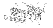
図6は、実施の形態における空気調和機の表示体11の分解斜視図である。
図6に示すように、表示体11は、表示シート15、基板ホルダー14、基板13から主として構成されている。
表示体11は図3〜5に示すようにベース部材10aに固定され、さらにフィルタ清掃ユニット8に取り付けられている。また、ベース部材10aと表示体11との間にはバネ12を配置し、表示体11を前方側、すなわち表示パネル1aの裏面に押しつけた状態にしている。この状態で表示体11から照射される光は表示パネル1aの裏面に入射し、表示パネル1a内を透過して表示パネル1aの表面に所要の表示を行うことが可能となる。
[Display]
The structure and attachment of the
FIG. 6 is an exploded perspective view of the
As shown in FIG. 6, the
As shown in FIGS. 3 to 5, the
[基板]
基板13は、図6に示すようにLED13aが実装されたプリント基板であり、基板ホルダー14内に固定されている。LED13aは、表示に必要なものが点灯または点滅するように制御される。
[表示シート]
図7は、実施の形態における空気調和機の表示シートの正面図である。
図8は、実施の形態における空気調和機の表示シートの突出構造の説明図である。
表示シート15は、PETなどの基材に印刷が施されたものであり、表示パネル1aの裏面に投射される数字、記号、イラスト等の輪郭を縁取り印刷したものである。表示内容は、図7に示すように例えば室温、設定温度、湿度などを数字で表す表示(図7(a)参照)や、風向設定位置を点灯する表示(図7(b)参照)や、エコ運転度を棒グラフで表す表示(図7(c)参照)などが考えられる。
[substrate]
As shown in FIG. 6, the
[Display sheet]
FIG. 7 is a front view of a display sheet of the air conditioner according to the embodiment.
FIG. 8 is an explanatory diagram of the protruding structure of the display sheet of the air conditioner according to the embodiment.
The
図8(a)は、表示シート15の断面図である。
図8(b)は、表示シート15の正面図である。
図8(c)は、表示シート15の突出部15cのエリアを示す正面図である。
表示シート15は、図8(a)に示すようにベース面15bと、ベース面15bよりも室内機の前面側に突出した突出部15cが段差部を境界として形成されている。
ベース面15bは光が透過しない印刷層が形成されており、突出部15cには印刷層に対して基板13からの光を通過させる非印刷部15aが印刷層の中に部分的に形成されている。
非印刷部15aは表示内容を表す文字や記号の形状となっている。
すなわち、表示シート15は、印刷層に対して非印刷部15aを部分的に含む部分が、ベース面15bより室内機の前面側に押し出された突出部15cとなって形成されている。
そして、表示シート15は、基板ホルダー14の前面側の前端面14bに接着剤で貼り付けられている。
FIG. 8A is a cross-sectional view of the
FIG. 8B is a front view of the
FIG. 8C is a front view showing the area of the protruding
As shown in FIG. 8A, the
A printed layer that does not transmit light is formed on the
The
In other words, the
The
[基板ホルダー]
基板ホルダー14は、ABS等の樹脂材料からボックス状に成形されており、表示素子としてのLED13aが挿入される位置に貫通穴14aが開口している。また、この貫通穴14aは表示シート15の非印刷部15aの位置にも対応している。
つまり、LED13aと貫通穴14aと表示シート15の非印刷部15aは前後に並んだ位置関係となる。
表示装置10はこのように構成されているので、基板13のLED13aから発した光を表示シート15の非印刷部15aに透過させ、表示パネル1aの裏側に光を到達させることができる。
[Substrate holder]
The
That is, the
Since the
次に表示体11が前面意匠パネル1内に収納される構造を説明する。
図4に示すように表示体11の基板ホルダー14とベース部材10aとの間には左右両側にバネ12が配設されている。バネ12のストロークは表示パネル1aの反りや表示装置10の組立時の寸法のばらつきを十分に吸収できる長さとなっている。
したがって、前面意匠パネル1が開いた状態では、基板ホルダー14がバネ12により筐体2の前面より多少突出した状態で前方へ付勢されており、前面意匠パネル1を閉じたときには、基板ホルダー14がバネ12により表示シート15を介して表示パネル1aの裏面に押し付けられている。
Next, the structure in which the
As shown in FIG. 4, springs 12 are disposed on the left and right sides between the
Therefore, when the
この表示体11の取り付け構造では、基板ホルダー14がバネ12の軸方向から数度傾いた方向へ動くことができるようになっている。このため、基板ホルダー14はバネ12により前後方向の動きのほか、左右・上下方向への傾動が可能になっている。
In the mounting structure of the
前面意匠パネル1は樹脂材料で成形されているので、多少なりとも反りが生じることがある。また、表示体11を表示装置10に組み込む際の組立や、筐体2への取付等においても寸法のばらつきが生じることがある。このような、前面意匠パネル1の反りや表示装置10の組立等のばらつきが原因で、表示パネル1aと表示シート15との間の隙間が1mm程度以上になると、表示パネル1a表面の表示がぼやけてしまう。
Since the
そこで、バネ12によって上記原因となる反りやばらつきを吸収することにしている。すなわち、バネ12により基板ホルダー14の前端面14bを筐体2の前面より突出させるとともに、基板ホルダー14の左右および上下方向の傾動を可能にしている。
このように表示体11を表示パネル1aの背面に押しつける際に表示体11の姿勢を微調整することが可能となることで、表示体11の表示シート15と表示パネル1aを密着させることができ、両部材の隙間を小さくすることができる。
Accordingly, the
In this way, when the
[表示パネル]
図9は、実施の形態における空気調和機の表示パネルの薄肉部と表示シートの突出部の関係を表す断面図である。
図9(a)は、表示パネル1aを室内機の正面側から見た斜視図である。
図9(b)は、図9(a)の表示パネル1aをZ−Z部分から見た断面図である。
図9(c)は、図9(a)の表示パネル1aをY−Y部分から見た断面図である。
表示パネル1aは、前述のように半透明な着色樹脂材料(例えば、ABS、ポリエチレン、ポリカーボネート等)で成形されている。
その断面形状は、図9(b)、(c)の断面図に示すように標準肉厚部1dと薄肉部1cにより成型されている。
この薄肉部1cは、表示パネル1aの裏面側に設けた表示体11からの光を表面側に透過させるために表示パネル1aの裏面に凹形状として部分的に設けたものである。
[Display panel]
FIG. 9 is a cross-sectional view illustrating the relationship between the thin portion of the display panel of the air conditioner and the protruding portion of the display sheet in the embodiment.
Fig.9 (a) is the perspective view which looked at the display panel 1a from the front side of the indoor unit.
FIG. 9B is a cross-sectional view of the display panel 1a of FIG.
FIG. 9C is a cross-sectional view of the display panel 1a of FIG.
The display panel 1a is formed of a translucent colored resin material (for example, ABS, polyethylene, polycarbonate, etc.) as described above.
The cross-sectional shape is formed by the standard
The
ここで、表示パネル1aの裏面側に表示体11の表示シート15を密着させる構成を説明する。
図9(b)、(c)の表示パネル1a部分の断面図に示されるように、表示パネル1aの薄肉部1cに表示シート15の突出部15cが嵌合するように組み合わされて構成される。また、表示パネル1aの標準肉厚部1dには表示シート15の周囲のベース面15bが接触もしくは近接する構成となる。
この構成により、基板13のLED13aから発せられた光は突出部15cの非印刷部15aを通過し、表示パネル1aの薄肉部1cを透過して表示パネル1aの表面に到達する。
Here, the structure which adhere | attaches the
As shown in the cross-sectional views of the display panel 1a in FIGS. 9B and 9C, the
With this configuration, the light emitted from the
このように表示パネル1aの薄肉部1cに表示シート15の突出部15cが接触もしくは近接する構成となるので、突出部15cに設けられた非印刷部15aから照射された光が表示シート15と表示パネル1aとの間で拡散することなく表示パネル1aの背面に入射することが可能となる。
したがって、表示パネル1aの表面に表示される数字、記号、イラスト等は、輪郭がぼやけることなく鮮明に表示されることとなる。
また、標準肉厚部1dに比べて肉厚の薄い薄肉部1cを光が透過することにより、光量の減衰率が小さくなり、より鮮明な表示を実現することが可能となる。
Thus, since the
Therefore, numbers, symbols, illustrations, and the like displayed on the surface of the display panel 1a are clearly displayed without blurring the outline.
Further, the light is transmitted through the
さらに、上述のように表示体11をバネ12により表示パネル1aの裏面に姿勢変化が可能に押しつける構成となっているため、表示シート15の突出部15cと表示パネル1aの薄肉部1cを密着することができる。
よって、これらの構成の相乗効果により、さらに鮮明な表示が可能となる。また、表示パネル1aへの塗装や印刷の工程が不要であるため低コスト化を実現することができる。
Further, as described above, the
Therefore, a clearer display is possible by the synergistic effect of these configurations. In addition, since the process of painting or printing on the display panel 1a is unnecessary, cost reduction can be realized.
上記実施の形態では、表示装置10を空気調和機の室内機に配置する例を示したが、表示部の表面を着色樹脂で成形した様々な製品に採用が可能である。例えば、洗濯機や冷蔵庫、掃除機などの家電製品や、表示盤を有する電器機器などその用途は本実施の形態に限定されるものではない。
In the said embodiment, although the example which arrange | positions the
1 前面意匠パネル、1a 表示パネル、1b メインパネル、1c 薄肉部、1d 標準肉厚部、2 筐体、2a 枠、3 ドレンパン組立体、4 電気品箱、5 熱交換器、6 送風ファン、7 基台、8 フィルタ清掃ユニット、10 表示装置、10a ベース部材、10b センサー、11 表示体、12 バネ、13 基板、13a LED、14 基板ホルダー、14a 貫通穴、14b 前端面、15 表示シート、15a 非印刷部、15b ベース面、15c 突出部。
DESCRIPTION OF
Claims (6)
光が透過しない印刷層と、光が透過する非印刷部と、を有する表示シートを備え、前記表示パネルの裏面側に設置されて前記表示パネルに光を投射する表示体と、
を備えた表示装置であって、
前記表示シートは、前記印刷層が形成されたベース面と、前記ベース面から突出して形成され、前記印刷層の中に部分的に前記非印刷部を設けた突出部と、を有し、
前記表示パネルの前記薄肉部には、前記表示シートの前記突出部が接触もしくは近接して、前記突出部における前記非印刷部を透過した光が前記表示パネルの表面に表示されることを特徴とする表示装置。 A display panel formed of a colored resin capable of transmitting light, and having a standard thick part, and a thin part having a concave shape on the back surface and being thinner than the standard thick part;
A printing layer which does not transmit light, and a display body including a non-print portion which light is transmitted, the display sheet having, for projecting light to the display panel installed on the back side of the display panel,
A display device provided with,
The display sheet comprises a base surface on which the print layer is formed, is formed to protrude from the base surface, have, a protrusion having a part on the non-printing portion in the printing layer,
The thin portion of the display panel is in contact with or close to the protrusion of the display sheet, and light transmitted through the non-printing portion of the protrusion is displayed on the surface of the display panel. Display device.
前記表示体と前記ベース部材との間には、前記表示体を前記表示パネルの裏面方向に付勢するバネを設けたことを特徴とする請求項1〜3のいずれか1項に記載の表示装置。 The display device has a base member,
The display according to any one of claims 1 to 3, wherein a spring is provided between the display body and the base member to urge the display body toward the back surface of the display panel. apparatus.
前記基板ホルダーは前記発光素子が収納される貫通穴を備え、
前記表示シートの前記非印刷部は前記貫通穴に面した位置に配置されることを特徴とする請求項1〜4のいずれか1項に記載の表示装置。 The display body includes a substrate provided with a light emitting element, and a substrate holder for fixing the substrate and attaching the display sheet,
The substrate holder includes a through hole in which the light emitting element is accommodated,
The display device according to claim 1, wherein the non-printing portion of the display sheet is disposed at a position facing the through hole.
Priority Applications (2)
| Application Number | Priority Date | Filing Date | Title |
|---|---|---|---|
| JP2013153681A JP5921501B2 (en) | 2013-07-24 | 2013-07-24 | Display device and air conditioner indoor unit provided with the same |
| CN201420347983.1U CN204026917U (en) | 2013-07-24 | 2014-06-26 | Display unit and possess the indoor set of air conditioner of this display unit |
Applications Claiming Priority (1)
| Application Number | Priority Date | Filing Date | Title |
|---|---|---|---|
| JP2013153681A JP5921501B2 (en) | 2013-07-24 | 2013-07-24 | Display device and air conditioner indoor unit provided with the same |
Publications (3)
| Publication Number | Publication Date |
|---|---|
| JP2015025862A JP2015025862A (en) | 2015-02-05 |
| JP2015025862A5 JP2015025862A5 (en) | 2015-08-06 |
| JP5921501B2 true JP5921501B2 (en) | 2016-05-24 |
Family
ID=52066765
Family Applications (1)
| Application Number | Title | Priority Date | Filing Date |
|---|---|---|---|
| JP2013153681A Active JP5921501B2 (en) | 2013-07-24 | 2013-07-24 | Display device and air conditioner indoor unit provided with the same |
Country Status (2)
| Country | Link |
|---|---|
| JP (1) | JP5921501B2 (en) |
| CN (1) | CN204026917U (en) |
Families Citing this family (1)
| Publication number | Priority date | Publication date | Assignee | Title |
|---|---|---|---|---|
| CN207515189U (en) * | 2016-08-02 | 2018-06-19 | 三菱电机株式会社 | The indoor unit of air-conditioning device |
Family Cites Families (11)
| Publication number | Priority date | Publication date | Assignee | Title |
|---|---|---|---|---|
| JPH0422388Y2 (en) * | 1986-10-31 | 1992-05-21 | ||
| JPH01205193A (en) * | 1988-02-12 | 1989-08-17 | Koito Mfg Co Ltd | Display device |
| JPH026987A (en) * | 1988-03-08 | 1990-01-11 | Fuji Electric Co Ltd | Front part decoration mechanism for electric equipment |
| JPH0792917A (en) * | 1993-09-27 | 1995-04-07 | Toshiba Corp | Operation panel |
| JPH0997026A (en) * | 1995-09-29 | 1997-04-08 | Nissha Printing Co Ltd | Display panel and its production |
| JP2000284732A (en) * | 1999-03-31 | 2000-10-13 | Nippon Seiki Co Ltd | Display device |
| JP2005003334A (en) * | 2003-06-16 | 2005-01-06 | Matsushita Electric Ind Co Ltd | Light emissive display device for air cleaner |
| JP3642064B2 (en) * | 2003-09-01 | 2005-04-27 | ダイキン工業株式会社 | Indoor unit for air conditioner and method for manufacturing the same |
| JP2010121861A (en) * | 2008-11-20 | 2010-06-03 | Daikin Ind Ltd | Air conditioner |
| EP2309477A1 (en) * | 2009-10-09 | 2011-04-13 | Braun GmbH | Display panel |
| JP5611153B2 (en) * | 2011-08-30 | 2014-10-22 | 三菱電機株式会社 | Air conditioner indoor unit |
-
2013
- 2013-07-24 JP JP2013153681A patent/JP5921501B2/en active Active
-
2014
- 2014-06-26 CN CN201420347983.1U patent/CN204026917U/en not_active Expired - Fee Related
Also Published As
| Publication number | Publication date |
|---|---|
| CN204026917U (en) | 2014-12-17 |
| JP2015025862A (en) | 2015-02-05 |
Similar Documents
| Publication | Publication Date | Title |
|---|---|---|
| JP4931749B2 (en) | Air conditioner indoor unit | |
| CN108369026B (en) | Air conditioner | |
| JP2009079787A5 (en) | ||
| JP3806881B2 (en) | Indoor unit of air conditioner | |
| JP4631644B2 (en) | Air conditioner indoor unit | |
| JP5258696B2 (en) | Air conditioner indoor unit | |
| JP5921501B2 (en) | Display device and air conditioner indoor unit provided with the same | |
| JP5611153B2 (en) | Air conditioner indoor unit | |
| JP4864130B2 (en) | Air conditioner indoor unit | |
| JP5099038B2 (en) | Air conditioner | |
| JP2015212780A (en) | Vehicle-mounted head-up display device | |
| KR101533315B1 (en) | Air conditioner | |
| JP7177979B2 (en) | Remote control device | |
| JP6008230B2 (en) | Operating device | |
| JP3850221B2 (en) | Air conditioner | |
| TWI626672B (en) | Cover mechanism and switch device provided with the cover mechanism | |
| JP2008289798A (en) | End rail for game machine installation island | |
| JP4255241B2 (en) | Air conditioner | |
| JP2011163616A (en) | Display device and indoor unit for air conditioner | |
| JP6057851B2 (en) | Fan | |
| CN113168982B (en) | Device and operating device | |
| WO2011029382A1 (en) | Wall-hanging type air conditioner with changeable pictures | |
| KR100465706B1 (en) | The display panel of a washer | |
| JP6967269B2 (en) | Remote controller for water heater | |
| KR101218038B1 (en) | Clock device |
Legal Events
| Date | Code | Title | Description |
|---|---|---|---|
| A521 | Request for written amendment filed |
Free format text: JAPANESE INTERMEDIATE CODE: A523 Effective date: 20150619 |
|
| A621 | Written request for application examination |
Free format text: JAPANESE INTERMEDIATE CODE: A621 Effective date: 20150619 |
|
| A977 | Report on retrieval |
Free format text: JAPANESE INTERMEDIATE CODE: A971007 Effective date: 20151015 |
|
| A131 | Notification of reasons for refusal |
Free format text: JAPANESE INTERMEDIATE CODE: A131 Effective date: 20151027 |
|
| A521 | Request for written amendment filed |
Free format text: JAPANESE INTERMEDIATE CODE: A523 Effective date: 20151225 |
|
| TRDD | Decision of grant or rejection written | ||
| A01 | Written decision to grant a patent or to grant a registration (utility model) |
Free format text: JAPANESE INTERMEDIATE CODE: A01 Effective date: 20160315 |
|
| A61 | First payment of annual fees (during grant procedure) |
Free format text: JAPANESE INTERMEDIATE CODE: A61 Effective date: 20160412 |
|
| R150 | Certificate of patent or registration of utility model |
Ref document number: 5921501 Country of ref document: JP Free format text: JAPANESE INTERMEDIATE CODE: R150 |
|
| R250 | Receipt of annual fees |
Free format text: JAPANESE INTERMEDIATE CODE: R250 |
|
| R250 | Receipt of annual fees |
Free format text: JAPANESE INTERMEDIATE CODE: R250 |
|
| R250 | Receipt of annual fees |
Free format text: JAPANESE INTERMEDIATE CODE: R250 |
|
| R250 | Receipt of annual fees |
Free format text: JAPANESE INTERMEDIATE CODE: R250 |
|
| R250 | Receipt of annual fees |
Free format text: JAPANESE INTERMEDIATE CODE: R250 |