JP5921195B2 - Providing tactile feedback to the instrument handle - Google Patents
Providing tactile feedback to the instrument handle Download PDFInfo
- Publication number
- JP5921195B2 JP5921195B2 JP2011546271A JP2011546271A JP5921195B2 JP 5921195 B2 JP5921195 B2 JP 5921195B2 JP 2011546271 A JP2011546271 A JP 2011546271A JP 2011546271 A JP2011546271 A JP 2011546271A JP 5921195 B2 JP5921195 B2 JP 5921195B2
- Authority
- JP
- Japan
- Prior art keywords
- instrument
- user
- handle
- haptic
- sensor
- Prior art date
- Legal status (The legal status is an assumption and is not a legal conclusion. Google has not performed a legal analysis and makes no representation as to the accuracy of the status listed.)
- Active
Links
Images


Classifications
-
- A—HUMAN NECESSITIES
- A61—MEDICAL OR VETERINARY SCIENCE; HYGIENE
- A61B—DIAGNOSIS; SURGERY; IDENTIFICATION
- A61B17/00—Surgical instruments, devices or methods, e.g. tourniquets
- A61B17/28—Surgical forceps
- A61B17/29—Forceps for use in minimally invasive surgery
- A61B17/2909—Handles
-
- A—HUMAN NECESSITIES
- A61—MEDICAL OR VETERINARY SCIENCE; HYGIENE
- A61B—DIAGNOSIS; SURGERY; IDENTIFICATION
- A61B34/00—Computer-aided surgery; Manipulators or robots specially adapted for use in surgery
- A61B34/70—Manipulators specially adapted for use in surgery
- A61B34/76—Manipulators having means for providing feel, e.g. force or tactile feedback
-
- A—HUMAN NECESSITIES
- A61—MEDICAL OR VETERINARY SCIENCE; HYGIENE
- A61B—DIAGNOSIS; SURGERY; IDENTIFICATION
- A61B90/00—Instruments, implements or accessories specially adapted for surgery or diagnosis and not covered by any of the groups A61B1/00 - A61B50/00, e.g. for luxation treatment or for protecting wound edges
- A61B90/06—Measuring instruments not otherwise provided for
- A61B2090/064—Measuring instruments not otherwise provided for for measuring force, pressure or mechanical tension
- A61B2090/065—Measuring instruments not otherwise provided for for measuring force, pressure or mechanical tension for measuring contact or contact pressure
Description
本開示は、包括的には、手持ち器具の実施の形態に関する。より詳細には、本開示は、対象の特性を感知すること、及び器具のハンドルに取り付けられる1つ又は複数の触覚作動装置へ触覚フィードバックを提供することに関する。 The present disclosure relates generally to handheld device embodiments. More particularly, the present disclosure relates to sensing subject characteristics and providing haptic feedback to one or more haptic actuators attached to the handle of the instrument.
外科医が内臓器官にアクセスするために患者の皮膚に比較的大きな切開部を形成する観血手術とは対照的に、比較的小さい切開部を作り、次いでこの切開部を通して器具を挿入して器官にアクセスすることによる、低侵襲性外科手術が行われている。通常、低侵襲性外科手術は結果として、入院期間がより短くなり、治療要件が減り、痛みが少なく、傷跡が小さく、合併症の可能性が低いこと等をもたらす。 In contrast to open surgery where the surgeon makes a relatively large incision in the patient's skin to gain access to the internal organs, a relatively small incision is made, and then an instrument is inserted through the incision into the organ. Access is undergoing minimally invasive surgery. Usually, minimally invasive surgery results in shorter hospital stays, fewer treatment requirements, less pain, less scars, less likely complications, and so forth.
外科医は、低侵襲性外科手術中に、切開部を通して小型カメラを導入することができる。このカメラは、画像をビジュアルディスプレイへ送信し、外科医が内臓器官及び組織を見ること、並びに器官及び組織にある他の低侵襲性器具の効果を確かめることを可能にする。このように、外科医は、腹腔鏡手術、切開、焼灼、内視鏡検査、遠隔手術等を行うことができる。しかしながら、低侵襲性外科手術には、観血手術と比較して、外科医が患者の器官及び組織を見て触るという能力に関して限界が存在する可能性がある。 The surgeon can introduce a small camera through the incision during minimally invasive surgery. This camera sends the image to a visual display, allowing the surgeon to see internal organs and tissues and to verify the effectiveness of other minimally invasive instruments in the organs and tissues. Thus, the surgeon can perform laparoscopic surgery, incision, cauterization, endoscopy, telesurgery, and the like. However, minimally invasive surgery may have limitations with respect to the ability of the surgeon to see and touch the patient's organs and tissues as compared to open surgery.
本開示は、感知したパラメータを器具の操作者へ伝える器具の複数の実施形態を記載する。特定の一実施形態によると、特に、本明細書に記載される器具は、ユーザの手の1本又は複数本の指と接触するように構成されるフィードバック部分を有するハンドルを備える。器具は、対象付近に、又は対象と接触して位置決めされると共に、対象の特性を測定するように構成されるセンサーをさらに含む。また、器具は、ハンドルのフィードバック部分によって支持される触覚出力機構を含む。触覚出力機構は、対象の測定した特性をユーザへ伝えるように構成される。 The present disclosure describes multiple embodiments of instruments that communicate sensed parameters to an operator of the instrument. In particular, according to one particular embodiment, the instrument described herein comprises a handle having a feedback portion configured to contact one or more fingers of a user's hand. The instrument further includes a sensor positioned near or in contact with the object and configured to measure the characteristics of the object. The instrument also includes a haptic output mechanism supported by the feedback portion of the handle. The haptic output mechanism is configured to communicate the measured characteristics of the object to the user.
本明細書において必ずしも明示的に開示されないかもしれないが、以下の詳細な説明及び添付の図面を検討すると当業者には明らかであろうさらなる特徴及び利点を、本開示に記載される実施形態は含み得る。これらのさらなる特徴及び利点は本開示内に含まれることが意図される。 Although not necessarily explicitly disclosed herein, the embodiments described in this disclosure provide additional features and advantages that will become apparent to those skilled in the art upon review of the following detailed description and the accompanying drawings. May be included. These additional features and advantages are intended to be included within the present disclosure.
以下の図の構成要素は、本開示の一般原理を強調するように示されており、必ずしも一定の縮尺で描かれていない。対応する構成要素を指す参照符号は、一貫性及び明確さの目的で図面を通して必要に応じて繰り返される。 The components in the following figures are shown to emphasize the general principles of the present disclosure and are not necessarily drawn to scale. Reference numerals referring to corresponding components are repeated as necessary throughout the drawings for purposes of consistency and clarity.
小切開部を伴う低侵襲性外科手術は観血手術に勝る多くの利点を含むが、低侵襲性外科手術は依然として外科医に課題をもたらす場合がある。例えば、外科医は通常、患者の内臓器官を見て器具の移動及び動作が器官にどのように影響を与えるかを確かめるのに、カメラに依存しなければならない。しかしながら、外科医の体験を高めるために、外科医にフィードバックを提供して患者の身体が器具に対してどのように反応するのかについての情報を伝えることができる。本開示の教示によると、器具のハンドルの或るセクションに触覚効果を与えることによって、外科医に出力を提供することができる。詳細には、触覚効果は、外科医の親指又はそれ以外の指を収容することが意図される器具のセクションに与えることができる。 Although minimally invasive surgery with a small incision includes many advantages over open surgery, minimally invasive surgery can still present challenges to the surgeon. For example, a surgeon typically has to rely on a camera to look at a patient's internal organs to see how instrument movement and movement affects the organ. However, to enhance the surgeon's experience, feedback can be provided to the surgeon to convey information about how the patient's body reacts to the instrument. In accordance with the teachings of the present disclosure, an output can be provided to the surgeon by providing a haptic effect to a section of the instrument handle. In particular, the haptic effect can be applied to a section of the instrument that is intended to accommodate the surgeon's thumb or other finger.
本開示は、操作者が操作することができる任意の種類の器具に適用することができる多くの実施形態を記載する。より詳細には、本開示において記載される器具は、器具の遠位部分を機械的に制御するハンドル部分を含む。遠位部分に取り付けられるのは、器具と相互作用する対象のパラメータを感知するように構成される1つ又は複数のセンサーである。ハンドルに取り付けられる1つ又は複数の触覚出力機構に提供されるように設計される出力信号を得るために、感知した信号を処理することができる。 The present disclosure describes a number of embodiments that can be applied to any type of instrument that can be operated by an operator. More particularly, the instrument described in this disclosure includes a handle portion that mechanically controls the distal portion of the instrument. Attached to the distal portion is one or more sensors configured to sense a parameter of interest interacting with the instrument. The sensed signal can be processed to obtain an output signal that is designed to be provided to one or more haptic output mechanisms attached to the handle.
本開示において記載される例の多くは低侵襲性外科手術用器具等の外科用器具に関するが、本開示は、他の種類の器具も包含することが意図されることを理解されたい。加えて、本明細書中の例の多くは、外科患者と、患者の器官及び組織が外科用器具とどのように相互作用するのかとに関するが、本開示は、それぞれの器具の動作と相互作用するか又は該動作に対して反応することが意図される他の種類の対象も含むことも理解されたい。器具の他の特徴及び利点は本開示の一般原理を読んで理解すると当業者には明らかになる。これらの示唆される特徴及び利点も本明細書に含まれることが意図される。 Although many of the examples described in this disclosure relate to surgical instruments such as minimally invasive surgical instruments, it should be understood that the present disclosure is intended to encompass other types of instruments. In addition, although many of the examples herein relate to a surgical patient and how the patient's organs and tissues interact with the surgical instrument, the present disclosure relates to the operation and interaction of each instrument. It should also be understood to include other types of objects that are intended to or react to the action. Other features and advantages of the instrument will be apparent to those skilled in the art upon reading and understanding the general principles of the present disclosure. These suggested features and advantages are also intended to be included herein.
図1は、外科用器具10の一実施形態を示す図である。この図において、外科用器具10は、一端が小切開部を通して患者の腹部に挿入されるように構成される腹腔鏡器具として示される。この実施形態の外科用器具10は、ハンドル12と、シャフト14と、遠位部分16とを含む。シャフト14は、ハンドル12を遠位部分16へ接続し、ハンドル12のあらゆる機械的動作を遠位部分16へ伝えるように設計される。シャフト14はさらに、以下でより詳細に説明するように電気信号を遠位部分16からハンドル12へ伝え戻すように設計される。
FIG. 1 is a diagram illustrating one embodiment of a
図1の実施形態によると、遠位部分16が、先端18と、先端18に形成される感知装置20とを含む。図1に示されるように、先端18は把持装置であり、感知装置20は、把持装置の底部ジョーに接続される。しかしながら、外科用器具10は、任意の好適な機能を有する任意の好適な種類の先端を含み得ることを理解されたい。また、感知装置20は、それぞれの先端の任意の部分に接続することができる。いくつかの実施形態では、先端18を省いてもよく、感知装置20を、その意図する感知機能を行うように遠位部分16の別の部分に取り付けてもよい。これに関して、外科用器具10は、遠位部分16において1つ又は複数の信号を感知するという唯一の目的のための感知装置として具現することができる。図1の実施形態のいくつかの例によると、シャフト14は、長さが約20cm乃至30cmであり、先端18は、長さが約10mm乃至15mmであり得る。
According to the embodiment of FIG. 1, the distal portion 16 includes a
操作者は、ハンドル12を操作することによって、遠位部分16を患者の腹部へ挿入し、遠位部分16の先端18を制御することができる。外科医は、遠位部分16を挿入すると、感知装置20が患者の或る特定の領域と接触することができるようにハンドル12をさらに操作して先端18の場所及び向きを制御することができる。感知装置20は、患者の任意の所望のパラメータ、例えば脈、硬さ等を測定又は試験するようにそれぞれが構成される1つ又は複数のセンサーを含むことができる。感知装置20が必ずしも患者の特定の領域と接触する必要がないいくつかの実施形態では、先端18は、或る特定の非接触感知機能を達成するために感知装置20を位置決めするように制御することができる。
An operator can manipulate the
感知装置20は、被試験対象の任意の好適な特性を感知するように構成することができる。例えば、感知装置20は、抵抗性又は容量性の圧力感知技術を使用する圧力センサーとして構成することができる。代替的には、感知装置20は、歪ゲージ、圧電センサー、硬さセンサー等を含んでもよい。感知装置20は、歪ゲージとしては、接触力についてのさらなる情報を提供して、力の大まかなコース測定を細かく調整するように構成することができる。感知装置20は、圧電センサーとしては、対象の部分から反射する超音波信号を生成する伝送装置を含むことができる。この場合、感知装置20がエコー信号を検出して対象の場所を求めることができる。感知装置20は、結節、例えば腫瘍、又は患者の他の硬い領域を検出することができる硬さセンサーとして構成することもできる。
図1の実施形態では、外科用器具10のハンドル12は、外科医の手の親指を収容するように設計される受け部22を含む。ハンドル12はまた、外科医の手の下方の3本の指を収容する第2の受け部24と、外科医の手の人差し指を収容するように設計されるリセス26とを含む。本開示に記載される実施形態の多くにおいては、外科医の親指の受け部、例えば受け部22を詳細に説明する。しかしながら、同様の特徴部を、操作者の片手又は両手の他の指又は他の部分用に設計される他の受け部及びリセスのために実装してもよいことに留意されたい。これに関して、受け部の特徴部は、ハンドルの任意の部分において具現することができる。
In the embodiment of FIG. 1, the
外科医の親指に触覚効果を与えるために、1つ又は複数の触覚作動装置を受け部22に組み込むことができる。他の実施形態では、外科医の指及び手の他の部分に触覚効果を与えるために、1つ又は複数の触覚作動装置を、ハンドル12の、受け部24及びリセス26のような他の部分に組み込んでもよい。感知装置20が感知した信号は、必要に応じて処理され、感知した信号を外科医に伝えるために触覚作動装置に適用することができる。受け部22は概して、出力信号を外科医の親指の異なる面に伝えることができるように、親指を囲むように構成することができる。必要であれば、アダプタ又は補助的な材料を受け部22の内面に配置して、外科医の親指の周りの複数の点と適切に接触するようにしてもよい。このアダプタを使用して、例えば種々のユーザの異なる親指のサイズを考慮することができる。
One or more haptic actuators can be incorporated into the
ハンドル12は、ハンドル12のハウジング内に位置決めされ得る処理装置30も含むことができる。処理装置30は、感知装置20からの信号を処理すると共に、受け部22に形成される1つ又は複数の触覚作動装置に提供される出力信号を制御するように構成される。処理装置30は例えば、汎用プロセッサ若しくは特定用途向けプロセッサ、又はマイクロコントローラであり得る。いくつかの実施形態では、処理装置30は、データ及び/又は命令を記憶するメモリデバイスと関連付けられ得る。論理命令、コマンド及び/又はコードは、ソフトウェア、ファームウェア又はその両方において実装することができ、メモリ装置に記憶される。他の実施形態では、論理命令、コマンド及び/又はコードをハードウェアにおいて実装し、別個の論理回路、特定用途向け集積回路(Application Specific Integrated Circuit:ASIC)、プログラマブルゲートアレイ(PGA)、フィールドプログラマブルゲートアレイ(FPGA)等又はそれらの任意の組み合わせを用いて処理装置30に組み込むことができる。感知装置20に関して使用され得る感知機構の種類及び測定する特性の種類に応じて、処理装置30のアルゴリズムが、対象の種々の特徴を求めることができる。
The
受け部22に位置する触覚作動装置は、外科用器具10の遠位部分16において感知され、処理装置30によって処理された信号に基づいてフィードバック信号を提供するように構成することができる。触覚作動装置は、電磁モータ、電気活性ポリマー、又は信号に応答して変形するか若しくは形状を変える他の材料、硬さを変える材料若しくは機構、振動触知アクチュエータ、慣性アクチュエータ、圧電アクチュエータ等を含み得る。一例では、触覚作動装置は、接触力、圧力等を伝達するために使用することができる把持特徴を含み得る。
A haptic actuator located in the
さらに、ハンドル12は、「ロール」制御装置として使用することができる回転装置28を含む。回転装置28は、シャフト14に直接的又は間接的に接続することができ、シャフト14を、その軸を中心に回転させるように構成される。操作者が回転装置28を回転させると、シャフト14及び遠位部分16がそれに対応して回転する。したがって、操作者は、先端18及び感知装置20の回転向きを制御することができる。操作者は、感知モードにおいて、感知装置20を所望の向きに方向付け、患者の或る特定の領域のセンサー信号を得ることができる。一例では、感知装置20は、シャフト14の軸に対して実質的に垂直な方向にシャフト14又は遠位部分16とは面しないように取り付けることができる。回転装置28を回転させてロールを制御することによって、感知装置20は、視覚センサー、硬さセンサー又は他の好適な種類のセンサーを使用して血管系、腫瘍塊等を特定するために、周囲の組織を観察するように軸の周りをスイープすることができる。
In addition, the
図2は、器具のシャフト36に取り付けられるセンサー34の一実施形態を示す断面図である。シャフト36は、器具のハンドル部分と遠位部分とを接続するように構成することができ、遠位部分は、1つ又は複数の機能要素を含み得る。いくつかの実施形態では、シャフト36は、図1に示すシャフト14に対応し得る。センサー34は、シャフト36の遠位端部に、又はシャフト36の任意の部分に沿って取り付けられ得る。いくつかの実施形態では、センサー34は、器具の遠位端部に位置する先端の部分に取り付けることができる。
FIG. 2 is a cross-sectional view illustrating one embodiment of a
図2の実施形態によると、センサー34は、支持装置38と、支持装置38の周りに周方向に配置される複数の感知要素40とを含む。感知要素40のそれぞれは、シャフト36には面しない方向へ配向することができ、各感知要素40は、異なる角度方向に面する。これに関して、感知要素40が、患者のその周囲の領域を同時に感知することが可能である。感知要素40は、感知要素20に関して上述したような任意の好適な種類のセンサー及び機能を含み得ることを認識されたい。センサー34は、任意の数の感知要素40を含むことができ、任意の好適な場所、方向又は角度に位置決めすると共に配向することができる。いくつかの実施形態では、感知要素40は、特定の設計に従った所定のパターンで支持装置38に取り付けることができる。
According to the embodiment of FIG. 2, the
いくつかの実施形態では、感知要素40の数は、器具のハンドルの受け部又はリセスに位置決めされる触覚作動装置の数に対応し得る。例えば、感知要素40は、図1に示される受け部22に位置する触覚作動装置又は別のセットの作動装置と直接関連付けられ得る。詳細には、作動装置は、感知要素40が配置される方法と対応する方法で配置することができ、その逆もまた可能である。本明細書に示される実施形態によると、感知要素40は、実質的に円形の配置で形成又は支持することができる。加えて、作動装置及び感知要素40が同様の方法で配置される場合、各作動装置を、対応する感知要素40と適合させることができる。したがって、1つの作動装置は、配置の同じそれぞれの位置に位置する対応する感知要素40が感知した信号に基づいてフィードバックを提供するように設計することができる。センサー34は、センサー34を支持する外科用器具と相互作用するか又はこれに反応する、患者の1つ又は複数の特性を測定するように構成される。
In some embodiments, the number of sensing elements 40 may correspond to the number of haptic actuators positioned in the receptacle or recess of the instrument handle. For example, the sensing element 40 may be directly associated with a haptic actuator or another set of actuators located in the
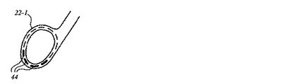
図3は、器具のハンドルの一部である受け部22−1の第1の実施形態を示す側断面図である。特に、受け部22−1はハンドルのフィードバック部分である。受け部22−1は、例えば、図1に示す外科用器具10の受け部22のあり得る実施形態に対応し得る。この実施形態では、受け部22−1は、複数の触覚作動装置44を含む。詳細には、この実施形態における触覚作動装置44の数は12個であり、これは、図2に示す感知要素40の同じ数と対応するものである。しかしながら、触覚作動装置44及び感知要素40の数は、同じであっても、異なっていても、倍数等であってもよいことに留意されたい。
FIG. 3 is a side sectional view showing a first embodiment of the receiving portion 22-1 which is a part of the handle of the instrument. In particular, the receiving part 22-1 is a feedback part of the handle. The receiver 22-1 may correspond to, for example, a possible embodiment of the
触覚作動装置44は、受け部22−1の材料によって任意の好適な方法で支持される。触覚作動装置44は、対応する群の感知要素が測定した患者の特性を伝えるように構成される。触覚作動装置44は、器具のユーザへ触覚効果を与える。より詳細には、受け部22−1は、ユーザの片手の親指を収容するように構成され得る。
The
触覚作動装置44は、受け部22−1にわたって分散させることができる。図示のように、触覚作動装置44は、実質的に円形の構成で配置される。各触覚作動装置44は、各感知要素40(図2)において感知される信号に基づいて触覚効果を与えるために、感知要素40等の各感知要素に対応するように構成することができる。触覚作動装置44の1つ又は複数は、受け部22−1の特定の場所に位置決めすることができ、シャフトに対する各感知要素の場所に対応する感知要素の感知した特性に基づいて作動される。
The
別の実施態様では、各触覚作動装置44は、感知装置20(図1)のような単一のセンサーが配向される特定の方向に対応するように構成することができる。別の実施形態に言及すると、1つ又は複数のセンサーを把持装置に取り付けることができ、触覚作動装置44は、把持装置のジョーに対する対象の部分の位置を伝えるように構成することができる。これに関して、対象の少しの部分しか把持装置のジョーの範囲内にない場合、少数の触覚作動装置44しか作動されない。
In another embodiment, each
図4A乃至図4Cは、第1の実施態様による、図3に示す触覚作動装置44の作動を示す図である。この実施形態では、触覚作動装置44は、方向情報をユーザへ伝えるように設計される。例えば、図1に示す処理装置30は、触覚作動装置44を制御して方向に関する情報を伝達するように構成することができる。一実施態様では、方向情報は、器具全体を物理的に旋回させることによって、又は回転装置28等の回転装置を回転させることによって制御することができる器具の先端の向きを表すことができる。加えて、方向情報は、センサーが対象、例えば患者と接触する場所を表すことができる。いくつかの場合では、感知したパラメータの方向は時間と共に変わり得る。例えば、脈は、第1の方向又は第1の場所において或る時点で検出され、次いでその直後に第2の方向又は第2の場所で検出され得る。
4A to 4C are diagrams showing the operation of the
図4Aに関して、受け部22−1の上部付近に位置する触覚作動装置44が、1つ又は複数のセンサーの上部、器具の上側部分、上方の向き等に関するセンサー情報に対応するように作動される。1つの例に関して、器具の遠位端部にある単一のセンサーが、上方方向に方向付けられるか又は配向されているときに、患者の特性、例えば硬さを感知することができる。別の例に関して、器具の遠位端部の周りに形成される1組のセンサーを使用して、上部領域に位置決めされているセンサーが特定のパラメータ、例えば硬さを検出するか、又は上部領域の特性が特定のレベルに達すると感知するようにすることができる。
With reference to FIG. 4A, a
図4Bに関しては、受け部22−1の一方の側又は両方の側の付近に位置する触覚作動装置44が作動される。これらの作動装置44の作動は、例えば、器具の遠位端部の左側領域又は右側領域から受信した患者のセンサー情報に対応することができる。例えば、単一のセンサーを使用する場合、いずれかの側に位置決めされる触覚作動装置44の作動は、その側に配向されるか又は方向付けられるセンサーに対応し得る。図4Bに示すように、左側及び右側いずれもの触覚作動装置44は同時に作動される。しかしながら、右側又は左側のいずれかのみの触覚作動装置44を一度に作動し、遠位端部の右側又は左側における特定の特徴を表してもよいことを認識されたい。器具の遠位端部において複数のセンサーを使用する場合、両側における触覚作動装置44の作動は、対応するセンサーにおいて感知される特定の信号に対応し得る。
With respect to FIG. 4B, the
図4Cに関しては、受け部22−1の底部付近に位置する触覚作動装置44が作動される。底部の触覚作動装置44の作動は、例えば、器具の遠位端部の底部領域から受信した患者のセンサー情報に対応し得る。単一のセンサーの場合、センサーの向きが下方方向である場合の特定の信号の検出によって、底部の触覚作動装置44を作動させることができる。代替的には、複数のセンサーを使用する場合、底部に位置決めされるか又は底部に方向付けられるセンサーからの特定の信号の検出によって、底部の触覚作動装置44を作動させることができる。
With respect to FIG. 4C, the
また、図4A乃至図4Cに示される触覚作動装置44を作動して、中心シャフトに対する端部分の方向又は向きを示すことができる。例えば、端部分は、中心シャフトに対して移動することができる多関節式把持装置を備え得る。この場合、その周辺の対応する領域に位置するこれらの触覚作動装置44を作動して、多関節式把持装置の頭部の向きを示すことができる。
Also, the
図5A乃至図5Cは、第2の実施態様による、図3に示す触覚作動装置44の作動を示す図である。この実施形態の触覚作動装置44は、任意の好適な種類の情報を回転式に伝えるように設計される。例えば、触覚作動装置44を作動して、血管を通る血流等の流れを示すことができる。代替的には、触覚作動装置44を作動して、管状構造等の構造を示してもよい。
5A to 5C are diagrams showing the operation of the
これらの3つの図は、或る特定の触覚作動装置44の順次の時点での作動を示す。この例に示されるように、受け部22−1の上部付近に位置するいくつかの触覚作動装置44が一度に作動される。その後の時点では、側部の触覚作動装置44が作動される。次いで、底部の触覚作動装置44が作動される。この意味では、時計回りの作動シーケンスが適用される。他の実施形態では、触覚作動装置44を、対象の任意の関連する特徴を伝えるために反時計回りに作動してもよい。この作動パターンを用いて、患者の任意のパラメータ又は特徴を示すことができる。例えば、作動シーケンスを用いて脈の感知を伝えることができる。
These three figures show the operation of a particular
図6A乃至図6Cは、第3の実施態様による、図3に示される触覚作動装置44の作動を示す図である。この実施形態の触覚作動装置44は、器具上の位置に対する位置情報又は空間的情報を伝えるように構成される。この場合、複数のセンサーをアレイ又は他の所定のパターンで位置決めし、特定のパラメータを感知するのに使用することができる。
6A to 6C are views showing the operation of the
これらの図は、例えば、把持装置、グリッパ又は他の同様の種類の機構のジョーの範囲内に保持される対象の量を伝えるための触覚作動装置44の可能な作動を示す。この場合、図6Aは、対象の少しの部分しかジョーに保持されない場合の、少数の触覚作動装置44の作動の例を示す。図6Bは、より多くの量の対象が器具に把持されている場合、例えばおよそ半分が器具に把持されている場合の、より多くの数の触覚作動装置44の作動の例を示す。図6Cは、器具が対象を完全に把持している場合の、受け部22−1の全て又はほとんど全ての触覚作動装置44の作動の例を示す。これは、大腸内視鏡検査中のような、患者の結腸に対して手術を行っている場合に特に有用であり得る。力をかけ過ぎると結腸が裂け、深刻な合併症を引き起こす可能性があるため、結腸を慎重に取り扱うことが重要である。これに関して、触覚作動装置44は、患者の結腸に印加されている把持の種類を外科医に伝えることができる。他の傷つきやすい器官も同様に或る特定のレベルの慎重さを必要とし得る。
These figures show possible actuations of the
図7は、器具のハンドルのフィードバック部分である受け部22−2の第2の実施形態を示す側面図である。例えば、受け部22−2は、図1に示される外科用器具10の受け部22の1つの可能な実施形態に対応し得る。この実施形態では、受け部22−2は、検査している対象の測定される特性に関する信号に応答して膨張及び収縮するように構成される材料を含む。例えば、対象に対する把持力又は他の種類の力を伝えるために、受け部22−2の材料はそれに従って膨張することができ、それによって、操作者の親指の全ての側面に力を印加する。この場合、ユーザの手に印加される力は、患者に印加される圧力を表す、器具の遠位端部で感知される圧力を伝達するより自然な感触を提供することができる。また、力フィードバックの種類の出力は、圧力の同様の測定を擬態するという利点を提供することができ、ユーザにとって、振動触知による感覚よりも集中を妨げないものとすることができる。
FIG. 7 is a side view showing a second embodiment of the receiving part 22-2 which is a feedback part of the handle of the instrument. For example, the receiver 22-2 may correspond to one possible embodiment of the
図7Aは、関連する信号が感知されていない場合のような、収縮している状態の受け部22−2を示す。しかしながら、図7Bでは、受け部22−2は膨張している状態で示されており、この場合、材料は通常の位置48から膨張した位置50へ膨張する。材料は、短い時間期間後、又は何らかの他の特定の事象後に信号がもはや感知されなくなると、その通常の位置48に戻るように構成することができる。いくつかの実施形態では、膨張及び収縮可能な材料をそれぞれのハンドルの他の部分において使用して、操作者の手の他の部分に圧力又は力を印加してもよい。
FIG. 7A shows the receptacle 22-2 in a contracted state, such as when the associated signal is not sensed. However, in FIG. 7B, the receptacle 22-2 is shown in an expanded state, where the material expands from the normal position 48 to the expanded
図8は、器具のハンドルのフィードバック部分である受け部22−3の第3の実施形態を示す側面図である。例えば、受け部22−3は、図1に示される外科用器具10の受け部22の1つの可能な実施形態に対応し得る。この実施形態では、受け部22−3はプログラム可能な突起54を含む。プログラム可能な突起54は、大きな不快感を生じさせることなくユーザへ情報を適切に伝える任意の好適なサイズ及び形状を有するように構成することができる。プログラム可能な突起54は、例えば方向情報、回転情報、1つ又は複数のセンサーに対する対象の相対位置等の任意の種類の情報をユーザへ伝えることができる。プログラム可能な突起54は、ユーザの親指の皮膚をわずかな力で押圧して親指とより接触し、親指の神経とよりよく連絡することができるように、受け部22−3の中心へ向かって突出するように設計される。
FIG. 8 is a side view showing a third embodiment of the receiving part 22-3 which is a feedback part of the handle of the instrument. For example, the receptacle 22-3 may correspond to one possible embodiment of the
プログラム可能な突起54は、感知した信号の詳細な状態を伝えるために膨張及び収縮するように構成することができる。いくつかの実施形態では、プログラム可能な突起54は、ユーザの親指に対して振動する又は別の種類の触覚効果を与えるように構成することができる。他の実施形態によると、プログラム可能な突起54は、感知した信号に従って硬さを変えるように構成してもよい。この場合、プログラム可能な突起54は、患者と接触している感知要素が行った硬さ測定に基づいてその硬さを変化させることができる。したがって、外科医は、器官及び組織の特定を助ける、硬さの指示を受け取ることができる。 Programmable protrusion 54 can be configured to expand and contract to convey the detailed state of the sensed signal. In some embodiments, the programmable protrusion 54 can be configured to vibrate or provide another type of haptic effect to the user's thumb. According to other embodiments, the programmable protrusion 54 may be configured to change hardness according to the sensed signal. In this case, the programmable protrusion 54 can change its hardness based on a hardness measurement made by a sensing element in contact with the patient. Thus, the surgeon can receive a hardness indication that helps identify the organs and tissues.
いくつかの実施形態では、それぞれが突起54と同様であり得る複数の突起が、受け部22−3の内面の周りに位置決めされる。各突起は、別個に、又は他の突起のいくつか若しくは全てと共に作動することができる。したがって、感知した信号を、突起の1つ又は複数の作動を含む方法で処理することができる。これに関して、突起は、方向、向き、流れ、相対的な状態の度合い若しくは段階等を示すように、図4乃至図6に関して説明した方法で作動することができる。 In some embodiments, a plurality of protrusions, each of which can be similar to the protrusion 54, are positioned around the inner surface of the receptacle 22-3. Each protrusion can operate separately or with some or all of the other protrusions. Thus, the sensed signal can be processed in a manner that includes one or more actuations of the protrusions. In this regard, the protrusions can operate in the manner described with respect to FIGS. 4-6 to indicate direction, orientation, flow, degree of relative state or stage, and the like.
図9は、ハンドル56のフィードバック部分の一実施形態を示す側断面図である。この実施形態では、ハンドル56は、ハンドル56の外面の下に位置決めされる複数の触覚作動装置58を含む。種々の配置に関して、触覚作動装置58は、ハンドル56の表面の下に、この面と面一に、この面の上に、又はこれらの任意の組み合わせで位置決めすることができる。これに関して、図9は、作動がハンドル56の外面からユーザに与えられる実施形態に関する。他方で、図3乃至図8は、指/親指の受け部の内面からユーザに与えられる触覚作動に関する実施形態を記載する。 FIG. 9 is a side cross-sectional view illustrating one embodiment of the feedback portion of handle 56. In this embodiment, the handle 56 includes a plurality of haptic actuators 58 positioned below the outer surface of the handle 56. With respect to various arrangements, the haptic actuator 58 can be positioned below the surface of the handle 56, flush with this surface, above this surface, or any combination thereof. In this regard, FIG. 9 relates to an embodiment in which actuation is provided to the user from the outer surface of the handle 56. On the other hand, FIGS. 3-8 describe embodiments relating to haptic actuation provided to the user from the inner surface of the finger / thumb receptacle.
ハンドル56は、触覚フィードバックを与えることが可能な任意の器具、特に、触覚作動がハンドル56の外面から印加される把持可能な器具の一部であり得る。ハンドル56のフィードバック部分は、電気ドリル、電気スクリュードライバ、自転車のハンドルバー、オートバイのハンドルバー、テニスラケット、ゴルフクラブ等の任意の種類の器具又は機器に組み込むことができる。さらに、触覚作動装置58は、図示のようにハンドル56の周囲に配置される場合、図4乃至図6に関して上述した作動技法と同様の方法で機能するようにプログラムすることができる。 The handle 56 can be part of any instrument capable of providing haptic feedback, in particular a graspable instrument where haptic actuation is applied from the outer surface of the handle 56. The feedback portion of the handle 56 can be incorporated into any type of equipment or device such as an electric drill, electric screwdriver, bicycle handlebar, motorcycle handlebar, tennis racket, golf club, and the like. In addition, the haptic actuator 58, when placed around the handle 56 as shown, can be programmed to function in a manner similar to the actuation technique described above with respect to FIGS.
図10は、そのハンドルへ触角フィードバックを提供する器具の動作方法の一実施形態のフロー図である。ブロック60に示されるように、ユーザー、すなわち操作者は、器具の通常使用によって器具を操作することができる。例えば、操作者は、器具のハンドル、ボタン又は他の特徴部を操作して器具の機能部分を制御することができる。機能部分は、例えば、器具のハンドルとは対向する端に位置決めされ得る。機能部分は、測定している特定の種類のパラメータに応じて、試験している対象と接触するか又は試験している対象に近接して配置するように周囲を調べることができる。
FIG. 10 is a flow diagram of one embodiment of a method of operating an instrument that provides tactile feedback to its handle. As shown in
ブロック62に示されるように、対象の1つ又は複数の特性を器具の遠位端部において感知する。特に、特性を1つ又は複数の感知装置によって感知することができる。センサーは、器具の機能部分に、又はその付近に位置決めすることができる。感知した特性は、器具の出力機構に印加される出力信号を得るために、必要に応じて処理することができる。出力信号は、感知される特性及び器具に組み込まれる出力機構の種類に基づいて、特定の用途に応じてそれぞれの個々の出力機構又は出力機構の全体のセットに関して得ることができる。
As shown in
ブロック64に示されるように、1つ又は複数の触覚効果を器具のハンドルの一部に与える。いくつかの実施形態では、他の出力信号を1つ又は複数の他の出力機構に提供してもよい。しかしながら、ブロック64によると、感知した信号は触覚によって操作者へ伝えられる。触覚効果は、触覚出力、振動触知効果出力等を含むことができる。
As shown in
本明細書に記載されるルーチン、ステップ、処理又は動作は、ソフトウェア又はファームウェアにおいて実装することができる任意のモジュール又はコードシーケンスを表し得ることを理解されたい。これに関して、これらのモジュール及びコードシーケンスは、物理的構成要素内で特定の論理ルーチン、ステップ、処理又は動作を実行するためのコマンド又は命令を含み得る。さらに、当業者には理解されるように、本明細書に記載されるルーチン、ステップ、処理及び/又は動作の2つ以上を、実質的に同時に、又は明示的に記載される順番とは異なる順番で実行することができることを理解されたい。 It should be understood that the routines, steps, processes or operations described herein may represent any module or code sequence that can be implemented in software or firmware. In this regard, these modules and code sequences may include commands or instructions for performing specific logical routines, steps, processes or operations within a physical component. Further, as will be appreciated by those skilled in the art, two or more of the routines, steps, processes and / or operations described herein may be substantially simultaneously or different from the order explicitly described. It should be understood that they can be performed in order.
本明細書に記載される実施形態は、複数の可能な実施態様及び例を示し、本開示を任意の特定の実施形態に必ずしも制限することを意図するものではない。その代わりに、当業者には理解されるように、これらの実施形態に対して種々の変更を加えることができる。そのようなあらゆる変更は、本開示の精神及び範囲内に含まれ、添付の特許請求の範囲内によって保護されることが意図される。 The embodiments described herein illustrate a number of possible implementations and examples and are not intended to necessarily limit the present disclosure to any particular embodiment. Instead, various modifications can be made to these embodiments, as will be appreciated by those skilled in the art. All such modifications are intended to be included within the spirit and scope of this disclosure and protected by the following claims.
Claims (8)
対象付近に、又は該対象と接触して位置決めされると共に、特性を測定するように構成されるセンサー(20、34)と、
前記ハンドル(12、56)の前記フィードバック部分内に分散しており、前記測定した特性に基づいて作動し、前記ユーザへフィードバックを提供するように構成される複数の触覚作動装置(44、58)と、
を備え、
前記フィードバック部分は、前記ユーザの手の1本又は複数本の指を収容するように構成される受け部(22、22−1、22−2、22−3、24)であり、
前記複数の触覚作動装置(44、58)は、前記受け部内に位置づけられる前記ユーザの手の1本又は複数本の指を囲むように、該受け部(22、22−1、22−2、22−3、24)の内面の周りに配置され、
前記複数の触覚作動装置のうち、作動する触覚作動装置は、前記センサーが測定した脈や血流に応じて、経時的に変化する、器具。
A handle (12, 56) having a feedback portion configured to contact one or more fingers of the user's hand;
Sensors (20, 34) positioned near or in contact with the object and configured to measure properties;
A plurality of haptic actuators (44, 58) distributed within the feedback portion of the handle (12, 56) and actuated based on the measured characteristics and configured to provide feedback to the user. When,
With
The feedback portion is a receiving portion (22, 22-1, 22-2, 22-3, 24) configured to receive one or more fingers of the user's hand;
The plurality of tactile activating devices (44, 58) are configured to surround the one or more fingers of the user's hand positioned in the receiving unit (22, 22-1, 22-2, disposed around the inner surface of 22-3,24),
Wherein among the plurality of tactile actuators, haptic actuating device for operation, said sensor response to pulsating and the blood flow was measured, you change over time, the instrument.
One or more of the haptic actuators (44, 58) positioned within the receptacle are actuated based in part on a corresponding direction in which the sensors (20, 34) are oriented. The instrument described in 1.
The sensor (20, 34) is oriented in a direction perpendicular to the shaft (14) connecting the handle (12, 56) and the distal end (16) of the instrument (10). The instrument of claim 1, wherein the instrument is configured.
前記ハンドル(12、56)と前記器具(10)の遠位端部(16)とを接続するシャフト(14)と、
対象付近に、又は該対象と接触して位置決めされると共に、特性を測定するように構成されるセンサー(20、34)であって、該センサー(20、34)は、前記シャフト(14)に対して垂直な方向に配向される複数の感知要素(40)を備え、該感知要素(40)はそれぞれ、前記対象の特性を測定するように構成される、センサー(20、34)と、
前記ハンドル(12、56)の前記フィードバック部分内に分散しており、前記測定した特性に基づいて作動し、前記ユーザへフィードバックを提供するように構成される複数の触覚作動装置(44、58)と、
を備え、
前記フィードバック部分は、前記ユーザの手の1本又は複数本の指を収容するように構成される受け部(22、22−1、22−2、22−3、24)であり、
前記複数の触覚作動装置(44、58)は、前記受け部内に位置づけられる前記ユーザの手の1本又は複数本の指を少なくとも部分的に囲むように、該受け部(22、22−1、22−2、22−3、24)の内面の周りに配置されており、
前記受け部内に位置決めされる前記触覚作動装置(44、58)の1つ又は複数は、一部では前記器具の前記シャフト(14)に対して対応する位置に位置決めされる1つ又は複数の感知要素(40)それぞれの感知した特性に基づいて作動され、
前記複数の触覚作動装置のうち、作動する触覚作動装置は、前記センサーが測定した脈や血流に応じて、経時的に変化する、器具。
A handle (12, 56) having a feedback portion configured to contact one or more fingers of the user's hand;
A shaft (14) connecting the handle (12, 56) and the distal end (16) of the instrument (10);
A sensor (20, 34) positioned near or in contact with an object and configured to measure properties, said sensor (20, 34) being attached to said shaft (14) A sensor (20, 34), comprising a plurality of sensing elements (40) oriented in a direction perpendicular to the sensor, each sensing element (40) configured to measure a property of the object;
A plurality of haptic actuators (44, 58) distributed within the feedback portion of the handle (12, 56) and actuated based on the measured characteristics and configured to provide feedback to the user. When,
With
The feedback portion is a receiving portion (22, 22-1, 22-2, 22-3, 24) configured to receive one or more fingers of the user's hand;
The plurality of tactile actuators (44, 58) are configured to at least partially surround one or more fingers of the user's hand positioned within the receiver. 22-2, 22-3, 24) around the inner surface,
One or more of the haptic actuators (44, 58) positioned in the receptacle are one or more sensing positioned in corresponding positions relative to the shaft (14) of the instrument in part. Actuated based on the sensed characteristics of each element (40) ,
Wherein among the plurality of tactile actuators, haptic actuating device for operation, said sensor response to pulsating and the blood flow was measured, you change over time, the instrument.
The sensor (20, 34) includes a plurality of sensing elements (40) attached to a gripping device, and the plurality of haptic actuators (44, 58) are positions of a portion of the object relative to the jaws of the gripping device. The instrument of claim 1, wherein the instrument is configured to communicate.
The receiving portions (22, 22-1, 22-2, 22-3, 24) are configured to accommodate the thumbs of the user, and the plurality of tactile actuators are configured such that the thumbs are the receiving portions (22). , 22-1, 22-2, 22-3, 24), wherein the measured characteristic is configured to be communicated to the user's thumb.
The instrument of claim 1, wherein the instrument (10) is a surgical instrument and the subject is a patient.
Applications Claiming Priority (3)
| Application Number | Priority Date | Filing Date | Title |
|---|---|---|---|
| US12/354,302 US8216212B2 (en) | 2009-01-15 | 2009-01-15 | Providing haptic feedback to the handle of a tool |
| US12/354,302 | 2009-01-15 | ||
| PCT/US2010/020010 WO2010083060A1 (en) | 2009-01-15 | 2010-01-04 | Providing haptic feedback to the handle of a tool |
Publications (3)
| Publication Number | Publication Date |
|---|---|
| JP2012515048A JP2012515048A (en) | 2012-07-05 |
| JP2012515048A5 JP2012515048A5 (en) | 2013-01-17 |
| JP5921195B2 true JP5921195B2 (en) | 2016-05-24 |
Family
ID=41728010
Family Applications (1)
| Application Number | Title | Priority Date | Filing Date |
|---|---|---|---|
| JP2011546271A Active JP5921195B2 (en) | 2009-01-15 | 2010-01-04 | Providing tactile feedback to the instrument handle |
Country Status (4)
| Country | Link |
|---|---|
| US (1) | US8216212B2 (en) |
| EP (1) | EP2303140B1 (en) |
| JP (1) | JP5921195B2 (en) |
| WO (1) | WO2010083060A1 (en) |
Families Citing this family (46)
| Publication number | Priority date | Publication date | Assignee | Title |
|---|---|---|---|---|
| US20100312129A1 (en) | 2005-01-26 | 2010-12-09 | Schecter Stuart O | Cardiovascular haptic handle system |
| US20110046659A1 (en) * | 2007-07-09 | 2011-02-24 | Immersion Corporation | Minimally Invasive Surgical Tools With Haptic Feedback |
| EP2417925B1 (en) | 2010-08-12 | 2016-12-07 | Immersion Corporation | Electrosurgical tool having tactile feedback |
| US8981914B1 (en) * | 2010-09-27 | 2015-03-17 | University of Pittsburgh—of the Commonwealth System of Higher Education | Portable haptic force magnifier |
| US20120116265A1 (en) | 2010-11-05 | 2012-05-10 | Houser Kevin L | Surgical instrument with charging devices |
| US10959769B2 (en) | 2010-11-05 | 2021-03-30 | Ethicon Llc | Surgical instrument with slip ring assembly to power ultrasonic transducer |
| US9000720B2 (en) | 2010-11-05 | 2015-04-07 | Ethicon Endo-Surgery, Inc. | Medical device packaging with charging interface |
| US10085792B2 (en) | 2010-11-05 | 2018-10-02 | Ethicon Llc | Surgical instrument with motorized attachment feature |
| US9017849B2 (en) | 2010-11-05 | 2015-04-28 | Ethicon Endo-Surgery, Inc. | Power source management for medical device |
| US9526921B2 (en) | 2010-11-05 | 2016-12-27 | Ethicon Endo-Surgery, Llc | User feedback through end effector of surgical instrument |
| US10660695B2 (en) | 2010-11-05 | 2020-05-26 | Ethicon Llc | Sterile medical instrument charging device |
| US9017851B2 (en) | 2010-11-05 | 2015-04-28 | Ethicon Endo-Surgery, Inc. | Sterile housing for non-sterile medical device component |
| US9381058B2 (en) | 2010-11-05 | 2016-07-05 | Ethicon Endo-Surgery, Llc | Recharge system for medical devices |
| US20120116381A1 (en) | 2010-11-05 | 2012-05-10 | Houser Kevin L | Surgical instrument with charging station and wireless communication |
| US9597143B2 (en) | 2010-11-05 | 2017-03-21 | Ethicon Endo-Surgery, Llc | Sterile medical instrument charging device |
| US9011471B2 (en) | 2010-11-05 | 2015-04-21 | Ethicon Endo-Surgery, Inc. | Surgical instrument with pivoting coupling to modular shaft and end effector |
| US9247986B2 (en) | 2010-11-05 | 2016-02-02 | Ethicon Endo-Surgery, Llc | Surgical instrument with ultrasonic transducer having integral switches |
| US9510895B2 (en) | 2010-11-05 | 2016-12-06 | Ethicon Endo-Surgery, Llc | Surgical instrument with modular shaft and end effector |
| US9649150B2 (en) | 2010-11-05 | 2017-05-16 | Ethicon Endo-Surgery, Llc | Selective activation of electronic components in medical device |
| US9039720B2 (en) | 2010-11-05 | 2015-05-26 | Ethicon Endo-Surgery, Inc. | Surgical instrument with ratcheting rotatable shaft |
| US9782215B2 (en) | 2010-11-05 | 2017-10-10 | Ethicon Endo-Surgery, Llc | Surgical instrument with ultrasonic transducer having integral switches |
| US9421062B2 (en) | 2010-11-05 | 2016-08-23 | Ethicon Endo-Surgery, Llc | Surgical instrument shaft with resiliently biased coupling to handpiece |
| US9782214B2 (en) | 2010-11-05 | 2017-10-10 | Ethicon Llc | Surgical instrument with sensor and powered control |
| CN103298424A (en) * | 2010-11-05 | 2013-09-11 | 伊西康内外科公司 | User feedback through handpiece of surgical instrument |
| US10881448B2 (en) | 2010-11-05 | 2021-01-05 | Ethicon Llc | Cam driven coupling between ultrasonic transducer and waveguide in surgical instrument |
| US9375255B2 (en) | 2010-11-05 | 2016-06-28 | Ethicon Endo-Surgery, Llc | Surgical instrument handpiece with resiliently biased coupling to modular shaft and end effector |
| US9072523B2 (en) | 2010-11-05 | 2015-07-07 | Ethicon Endo-Surgery, Inc. | Medical device with feature for sterile acceptance of non-sterile reusable component |
| US9161803B2 (en) | 2010-11-05 | 2015-10-20 | Ethicon Endo-Surgery, Inc. | Motor driven electrosurgical device with mechanical and electrical feedback |
| US9089338B2 (en) | 2010-11-05 | 2015-07-28 | Ethicon Endo-Surgery, Inc. | Medical device packaging with window for insertion of reusable component |
| WO2012074564A1 (en) | 2010-12-02 | 2012-06-07 | Freehand Endoscopic Devices, Inc. | Surgical tool |
| US8801710B2 (en) | 2010-12-07 | 2014-08-12 | Immersion Corporation | Electrosurgical sealing tool having haptic feedback |
| US8523043B2 (en) | 2010-12-07 | 2013-09-03 | Immersion Corporation | Surgical stapler having haptic feedback |
| US8942828B1 (en) | 2011-04-13 | 2015-01-27 | Stuart Schecter, LLC | Minimally invasive cardiovascular support system with true haptic coupling |
| US8845667B2 (en) * | 2011-07-18 | 2014-09-30 | Immersion Corporation | Surgical tool having a programmable rotary module for providing haptic feedback |
| WO2013036587A1 (en) * | 2011-09-07 | 2013-03-14 | St. Louis University | Foreign body location and retrieval device |
| DE102012200597A1 (en) * | 2012-01-17 | 2013-07-18 | Robert Bosch Gmbh | Device for signaling information to the driver of a bicycle |
| US10013082B2 (en) | 2012-06-05 | 2018-07-03 | Stuart Schecter, LLC | Operating system with haptic interface for minimally invasive, hand-held surgical instrument |
| US9443401B2 (en) | 2013-09-06 | 2016-09-13 | Immersion Corporation | Automatic remote sensing and haptic conversion system |
| WO2015150932A1 (en) | 2014-03-31 | 2015-10-08 | Koninklijke Philips N.V. | Haptic feedback for ultrasound image acquisition |
| US9880046B2 (en) * | 2014-05-15 | 2018-01-30 | Texas Instruments Incorporated | Method, apparatus and system for portable device surface and material analysis |
| US10136938B2 (en) | 2014-10-29 | 2018-11-27 | Ethicon Llc | Electrosurgical instrument with sensor |
| US10613629B2 (en) | 2015-03-27 | 2020-04-07 | Chad Laurendeau | System and method for force feedback interface devices |
| KR102016063B1 (en) * | 2018-05-09 | 2019-08-29 | 건국대학교 글로컬산학협력단 | Apparatus for providing touch pressure feedback of a laparoscopic grasper and method for operating thereof |
| JP2021192130A (en) | 2018-08-29 | 2021-12-16 | ソニーグループ株式会社 | Tactile presentation device and tactile presentation system |
| NL2022018B1 (en) * | 2018-11-16 | 2020-05-26 | Efi Holding B V | Surgical instrument |
| CN112120791B (en) * | 2020-09-30 | 2021-12-31 | 中国科学院深圳先进技术研究院 | Main end control device of vascular intervention surgical robot |
Family Cites Families (14)
| Publication number | Priority date | Publication date | Assignee | Title |
|---|---|---|---|---|
| JPH0538327A (en) * | 1991-04-23 | 1993-02-19 | Olympus Optical Co Ltd | Medical equipment |
| JPH06210581A (en) * | 1993-01-20 | 1994-08-02 | Olympus Optical Co Ltd | Manipulating device |
| US5389849A (en) * | 1993-01-20 | 1995-02-14 | Olympus Optical Co., Ltd. | Tactility providing apparatus and manipulating device using the same |
| DE4332580A1 (en) * | 1993-09-24 | 1995-03-30 | Deutsche Aerospace | Apparatus for reconstructing or simulating the sense of touch in a surgical instrument |
| JPH0890458A (en) * | 1994-09-21 | 1996-04-09 | Olympus Optical Co Ltd | Tactile sense transmitting device |
| US6436107B1 (en) | 1996-02-20 | 2002-08-20 | Computer Motion, Inc. | Method and apparatus for performing minimally invasive surgical procedures |
| JP2836577B2 (en) * | 1996-05-15 | 1998-12-14 | 日本電気株式会社 | Manipulator operation device |
| JPH1094512A (en) * | 1996-09-25 | 1998-04-14 | Olympus Optical Co Ltd | Taction detector |
| US6810281B2 (en) * | 2000-12-21 | 2004-10-26 | Endovia Medical, Inc. | Medical mapping system |
| US6969384B2 (en) * | 2000-01-03 | 2005-11-29 | The Johns Hopkins University | Surgical devices and methods of use thereof for enhanced tactile perception |
| EP1303853A4 (en) | 2000-05-24 | 2009-03-11 | Immersion Corp | Haptic devices using electroactive polymers |
| NL1018874C2 (en) | 2001-09-03 | 2003-03-05 | Michel Petronella Hub Vleugels | Surgical instrument. |
| AU2003238146A1 (en) | 2002-04-23 | 2003-11-10 | Yves Cadiou | Propeller with interactive blades |
| CA2520942C (en) | 2005-09-23 | 2013-03-19 | Queen's University At Kingston | Tactile amplification instrument and method of use |
-
2009
- 2009-01-15 US US12/354,302 patent/US8216212B2/en not_active Expired - Fee Related
-
2010
- 2010-01-04 WO PCT/US2010/020010 patent/WO2010083060A1/en active Application Filing
- 2010-01-04 JP JP2011546271A patent/JP5921195B2/en active Active
- 2010-01-04 EP EP10701044.9A patent/EP2303140B1/en not_active Not-in-force
Also Published As
| Publication number | Publication date |
|---|---|
| EP2303140A1 (en) | 2011-04-06 |
| US8216212B2 (en) | 2012-07-10 |
| EP2303140B1 (en) | 2015-03-25 |
| US20100179587A1 (en) | 2010-07-15 |
| WO2010083060A1 (en) | 2010-07-22 |
| JP2012515048A (en) | 2012-07-05 |
Similar Documents
| Publication | Publication Date | Title |
|---|---|---|
| JP5921195B2 (en) | Providing tactile feedback to the instrument handle | |
| EP2351528B1 (en) | Tool having multiple feedback devices | |
| JP5683482B2 (en) | Spatial array of sensors attached to the instrument | |
| US10561468B2 (en) | Apparatus and method for using a remote control system in surgical procedures | |
| US20190012006A1 (en) | Operating System with Haptic Interface for Minimally Invasive, Hand-Held Surgical Instrument | |
| EP2173255B1 (en) | Minimally invasive surgical tools with haptic feedback | |
| JP3230615B2 (en) | Palpation device | |
| King et al. | A multielement tactile feedback system for robot-assisted minimally invasive surgery | |
| JP6586955B2 (en) | Contact detection instrument | |
| US20130085511A1 (en) | Novel Tactile Feedback System for Robotic Surgery | |
| JP2023052889A (en) | User interface device having grip linkages | |
| WO2019240825A1 (en) | User interface device having finger clutch | |
| CA2965951C (en) | Devices, systems, and methods for locating pressure sensitive critical structures |
Legal Events
| Date | Code | Title | Description |
|---|---|---|---|
| RD04 | Notification of resignation of power of attorney |
Free format text: JAPANESE INTERMEDIATE CODE: A7424 Effective date: 20120713 |
|
| A521 | Request for written amendment filed |
Free format text: JAPANESE INTERMEDIATE CODE: A523 Effective date: 20121121 |
|
| A621 | Written request for application examination |
Free format text: JAPANESE INTERMEDIATE CODE: A621 Effective date: 20121121 |
|
| A977 | Report on retrieval |
Free format text: JAPANESE INTERMEDIATE CODE: A971007 Effective date: 20131016 |
|
| A131 | Notification of reasons for refusal |
Free format text: JAPANESE INTERMEDIATE CODE: A131 Effective date: 20131024 |
|
| A601 | Written request for extension of time |
Free format text: JAPANESE INTERMEDIATE CODE: A601 Effective date: 20140124 |
|
| A602 | Written permission of extension of time |
Free format text: JAPANESE INTERMEDIATE CODE: A602 Effective date: 20140131 |
|
| A521 | Request for written amendment filed |
Free format text: JAPANESE INTERMEDIATE CODE: A523 Effective date: 20140424 |
|
| A02 | Decision of refusal |
Free format text: JAPANESE INTERMEDIATE CODE: A02 Effective date: 20140722 |
|
| A521 | Request for written amendment filed |
Free format text: JAPANESE INTERMEDIATE CODE: A523 Effective date: 20141121 |
|
| A521 | Request for written amendment filed |
Free format text: JAPANESE INTERMEDIATE CODE: A821 Effective date: 20141121 |
|
| A911 | Transfer to examiner for re-examination before appeal (zenchi) |
Free format text: JAPANESE INTERMEDIATE CODE: A911 Effective date: 20141215 |
|
| A912 | Re-examination (zenchi) completed and case transferred to appeal board |
Free format text: JAPANESE INTERMEDIATE CODE: A912 Effective date: 20150206 |
|
| A521 | Request for written amendment filed |
Free format text: JAPANESE INTERMEDIATE CODE: A523 Effective date: 20160209 |
|
| A61 | First payment of annual fees (during grant procedure) |
Free format text: JAPANESE INTERMEDIATE CODE: A61 Effective date: 20160412 |
|
| R150 | Certificate of patent or registration of utility model |
Ref document number: 5921195 Country of ref document: JP Free format text: JAPANESE INTERMEDIATE CODE: R150 |
|
| R250 | Receipt of annual fees |
Free format text: JAPANESE INTERMEDIATE CODE: R250 |