JP5920966B2 - Supersonic compressor rotor and method of assembling it - Google Patents
Supersonic compressor rotor and method of assembling it Download PDFInfo
- Publication number
- JP5920966B2 JP5920966B2 JP2011181102A JP2011181102A JP5920966B2 JP 5920966 B2 JP5920966 B2 JP 5920966B2 JP 2011181102 A JP2011181102 A JP 2011181102A JP 2011181102 A JP2011181102 A JP 2011181102A JP 5920966 B2 JP5920966 B2 JP 5920966B2
- Authority
- JP
- Japan
- Prior art keywords
- flow path
- inlet
- outlet
- fluid
- supersonic compressor
- Prior art date
- Legal status (The legal status is an assumption and is not a legal conclusion. Google has not performed a legal analysis and makes no representation as to the accuracy of the status listed.)
- Active
Links
- 238000000034 method Methods 0.000 title description 11
- 239000012530 fluid Substances 0.000 claims description 110
- 230000006835 compression Effects 0.000 claims description 62
- 238000007906 compression Methods 0.000 claims description 62
- 230000007704 transition Effects 0.000 claims description 49
- 238000011144 upstream manufacturing Methods 0.000 claims description 27
- 230000035939 shock Effects 0.000 description 16
- 230000007423 decrease Effects 0.000 description 6
- 230000000712 assembly Effects 0.000 description 5
- 238000000429 assembly Methods 0.000 description 5
- 238000010586 diagram Methods 0.000 description 2
- 230000007246 mechanism Effects 0.000 description 2
- 239000000203 mixture Substances 0.000 description 2
- 238000013459 approach Methods 0.000 description 1
- 230000015572 biosynthetic process Effects 0.000 description 1
- 238000004891 communication Methods 0.000 description 1
- 238000012423 maintenance Methods 0.000 description 1
- 238000004519 manufacturing process Methods 0.000 description 1
- 238000012545 processing Methods 0.000 description 1
Images


Classifications
-
- F—MECHANICAL ENGINEERING; LIGHTING; HEATING; WEAPONS; BLASTING
- F04—POSITIVE - DISPLACEMENT MACHINES FOR LIQUIDS; PUMPS FOR LIQUIDS OR ELASTIC FLUIDS
- F04D—NON-POSITIVE-DISPLACEMENT PUMPS
- F04D21/00—Pump involving supersonic speed of pumped fluids
-
- F—MECHANICAL ENGINEERING; LIGHTING; HEATING; WEAPONS; BLASTING
- F04—POSITIVE - DISPLACEMENT MACHINES FOR LIQUIDS; PUMPS FOR LIQUIDS OR ELASTIC FLUIDS
- F04D—NON-POSITIVE-DISPLACEMENT PUMPS
- F04D17/00—Radial-flow pumps, e.g. centrifugal pumps; Helico-centrifugal pumps
- F04D17/02—Radial-flow pumps, e.g. centrifugal pumps; Helico-centrifugal pumps having non-centrifugal stages, e.g. centripetal
-
- F—MECHANICAL ENGINEERING; LIGHTING; HEATING; WEAPONS; BLASTING
- F04—POSITIVE - DISPLACEMENT MACHINES FOR LIQUIDS; PUMPS FOR LIQUIDS OR ELASTIC FLUIDS
- F04D—NON-POSITIVE-DISPLACEMENT PUMPS
- F04D17/00—Radial-flow pumps, e.g. centrifugal pumps; Helico-centrifugal pumps
- F04D17/08—Centrifugal pumps
- F04D17/10—Centrifugal pumps for compressing or evacuating
-
- F—MECHANICAL ENGINEERING; LIGHTING; HEATING; WEAPONS; BLASTING
- F04—POSITIVE - DISPLACEMENT MACHINES FOR LIQUIDS; PUMPS FOR LIQUIDS OR ELASTIC FLUIDS
- F04D—NON-POSITIVE-DISPLACEMENT PUMPS
- F04D29/00—Details, component parts, or accessories
- F04D29/26—Rotors specially for elastic fluids
- F04D29/28—Rotors specially for elastic fluids for centrifugal or helico-centrifugal pumps for radial-flow or helico-centrifugal pumps
- F04D29/284—Rotors specially for elastic fluids for centrifugal or helico-centrifugal pumps for radial-flow or helico-centrifugal pumps for compressors
Landscapes
- Engineering & Computer Science (AREA)
- Mechanical Engineering (AREA)
- General Engineering & Computer Science (AREA)
- Structures Of Non-Positive Displacement Pumps (AREA)
Description
本明細書に記載される主題は一般に超音速圧縮機システムに関し、より詳しくは超音速圧縮機システムと共に使用するための超音速圧縮機ロータに関する。 The subject matter described herein generally relates to a supersonic compressor system, and more particularly to a supersonic compressor rotor for use with a supersonic compressor system.
少なくともいくつかの既知の超音速圧縮機アセンブリは、吸気セクションと、排気セクションと、吸気セクションと排気セクションの間に配置される少なくとも1つの超音速圧縮機ロータとを含む。 At least some known supersonic compressor assemblies include an intake section, an exhaust section, and at least one supersonic compressor rotor disposed between the intake and exhaust sections.
既知の超音速圧縮機ロータは、ロータディスクに連結された複数のストレーキを含む。各ストレーキは、ロータディスクの周りで円周方向に配向され、隣接するストレーキ間に軸方向流路を画成する。少なくともいくつかの既知の超音速圧縮機ロータは、ロータディスクに連結される超音速圧縮ランプを含む。既知の超音速圧縮ランプは軸方向流れ経路内に配置され、この流れ経路内に圧縮波を形成するように構成される。既知の超音速圧縮機アセンブリは、流体を軸方向に導くのを助けるように軸方向に配向された流れ経路を含む吸気セクションを含む。さらに、少なくともいくつかの既知の超音速圧縮機アセンブリは、軸方向に配向される流体流れを既知の超音速圧縮機ロータから受け取るように構成される排気セクションを含む。 Known supersonic compressor rotors include a plurality of strakes coupled to a rotor disk. Each strut is oriented circumferentially around the rotor disk and defines an axial flow path between adjacent strakes. At least some known supersonic compressor rotors include a supersonic compression ramp coupled to a rotor disk. Known supersonic compression ramps are arranged in an axial flow path and are configured to form a compression wave in the flow path. Known supersonic compressor assemblies include an intake section that includes an axially oriented flow path to help direct fluid axially. In addition, at least some known supersonic compressor assemblies include an exhaust section configured to receive an axially oriented fluid flow from a known supersonic compressor rotor.
少なくともいくつかの既知の超音速圧縮機アセンブリの動作中、超音速圧縮機ロータは、高回転速度で回転する。流体は、吸気セクションから超音速圧縮機ロータまで軸方向に導かれ、その結果、超音速圧縮機ロータに対して超音速である速度によって特徴付けられる。少なくともいくつかの既知の超音速圧縮機ロータは、流体を軸方向に排気する。流体が軸方向に導かれるとき、超音速圧縮機ロータの下流側に配置される排気セクションは、軸方向に配向される流れを受け取るように設計する必要がある。既知の超音速圧縮機システムは、例えば、それぞれ2005年3月28日および2005年3月23日に出願された米国特許第7、334、990号および第7、293、955号、および2009年1月16日に出願された米国特許出願第2009/0196731号に記載されている。 During operation of at least some known supersonic compressor assemblies, the supersonic compressor rotor rotates at a high rotational speed. The fluid is directed axially from the intake section to the supersonic compressor rotor, and as a result is characterized by a speed that is supersonic relative to the supersonic compressor rotor. At least some known supersonic compressor rotors exhaust fluid axially. When the fluid is directed axially, the exhaust section located downstream of the supersonic compressor rotor needs to be designed to receive an axially oriented flow. Known supersonic compressor systems are described, for example, in US Pat. Nos. 7,334,990 and 7,293,955, filed Mar. 28, 2005 and Mar. 23, 2005, respectively. It is described in US Patent Application No. 2009/0196731 filed Jan. 16.
一実施形態では、超音速圧縮機ロータが提供される。この超音速圧縮機ロータは、上流側表面と、下流側表面と、上流側表面と下流側表面の間を延びる半径方向外側表面とを含むロータディスクを含む。この半径方向外側表面は、入口表面と、出口表面と、入口表面と出口表面の間を延びる移行表面とを含む。このロータディスクは、中央線軸を画成する。複数のベーンが、半径方向外側表面に連結される。隣接するベーンは、対を形成し、隣接するベーンの各対の間に流路が画成されるように配向される。流路は、入口開口部と出口開口部の間を延びる。入口表面は入口開口部と移行表面の間を延びる入口平面を画成する。出口表面は、出口開口部と入口平面に対して平行でない移行表面の間を延びる出口平面を画成する。少なくとも1つの超音速圧縮ランプが、流路内に少なくとも1つの圧縮波を形成するのを助けるように、流路内に配置される。 In one embodiment, a supersonic compressor rotor is provided. The supersonic compressor rotor includes a rotor disk that includes an upstream surface, a downstream surface, and a radially outer surface extending between the upstream surface and the downstream surface. The radially outer surface includes an inlet surface, an outlet surface, and a transition surface extending between the inlet surface and the outlet surface. The rotor disk defines a central line axis. A plurality of vanes are connected to the radially outer surface. Adjacent vanes form pairs and are oriented such that a flow path is defined between each pair of adjacent vanes. The flow path extends between the inlet opening and the outlet opening. The inlet surface defines an inlet plane that extends between the inlet opening and the transition surface. The exit surface defines an exit plane that extends between the exit opening and a transition surface that is not parallel to the entrance plane. At least one supersonic compression ramp is disposed in the flow path to help form at least one compression wave in the flow path.
別の実施形態では、超音速圧縮機システムが提供される。この超音速圧縮機システムは、流体入口と流体出口との間を延びる空洞を画成するケーシングを含む。駆動シャフトがケーシング内に配置され、中央線軸を画成する。駆動シャフトは駆動アセンブリに回転可能に連結される。超音速圧縮機ロータは駆動シャフトに連結される。超音速圧縮機ロータは、流体を流体入口から流体出口まで導くように流体入口と流体出口の間に配置される。超音速圧縮機ロータは、上流側表面と、下流側表面と、上流側表面と下流側表面の間を延びる半径方向外側表面とを含むロータディスクを含む。半径方向外側表面は、入口表面と、出口表面と、入口表面と出口表面の間を延びる移行表面とを含む。複数のベーンが半径方向外側表面に連結される。隣接するベーンは対を形成し、流路が隣接するベーンの各対の間に画成されるように配向される。流路は、入口開口部と出口開口部の間を延びる。入口表面は、入口開口部と移行表面の間を延びる入口平面を画成する。出口表面は出口開口部と入口平面に対して平行でない移行表面の間を延びる出口平面を画成する。少なくとも1つの超音速圧縮ランプが、流路内に少なくとも1つの圧縮波を形成するのを助けるように、流路内に配置される。 In another embodiment, a supersonic compressor system is provided. The supersonic compressor system includes a casing that defines a cavity extending between a fluid inlet and a fluid outlet. A drive shaft is disposed within the casing and defines a central axis. The drive shaft is rotatably coupled to the drive assembly. The supersonic compressor rotor is connected to the drive shaft. A supersonic compressor rotor is disposed between the fluid inlet and the fluid outlet to direct fluid from the fluid inlet to the fluid outlet. The supersonic compressor rotor includes a rotor disk that includes an upstream surface, a downstream surface, and a radially outer surface extending between the upstream surface and the downstream surface. The radially outer surface includes an inlet surface, an outlet surface, and a transition surface extending between the inlet surface and the outlet surface. A plurality of vanes are connected to the radially outer surface. Adjacent vanes form pairs and are oriented such that the flow path is defined between each pair of adjacent vanes. The flow path extends between the inlet opening and the outlet opening. The inlet surface defines an inlet plane that extends between the inlet opening and the transition surface. The exit surface defines an exit plane that extends between the exit opening and a transition surface that is not parallel to the entrance plane. At least one supersonic compression ramp is disposed in the flow path to help form at least one compression wave in the flow path.
さらに別の実施形態では、超音速圧縮機ロータを組み立てる方法が提供される。この方法は、上流側表面と、下流側表面と、上流側表面と下流側表面の間を延びる半径方向外側表面とを含むロータディスクを設けるステップを含む。半径方向外側表面は、入口表面と、出口表面と、入口表面と出口表面の間を延びる移行表面とを含む。ロータディスクは中央線軸を画成する。複数のベーンが半径方向外側表面に連結される。隣接するベーンは対を形成し、流路が隣接するベーンの各対の間に画成されるように配向される。流路は、入口開口部と出口開口部の間を延びる。入口表面は、入口開口部と移行表面の間を延びる入口平面を画成する。出口表面は、出口開口部と入口平面に対して平行でない移行表面の間を延びる出口平面を画成する。少なくとも1つの超音速圧縮ランプが、複数のベーンのうちのベーンの1つと半径方向外側表面とに連結される。超音速圧縮ランプは流路内に配置され、流路内に少なくとも1つの圧縮波を形成するのを助けるように構成される。 In yet another embodiment, a method for assembling a supersonic compressor rotor is provided. The method includes providing a rotor disk that includes an upstream surface, a downstream surface, and a radially outer surface extending between the upstream and downstream surfaces. The radially outer surface includes an inlet surface, an outlet surface, and a transition surface extending between the inlet surface and the outlet surface. The rotor disk defines a central line axis. A plurality of vanes are connected to the radially outer surface. Adjacent vanes form pairs and are oriented such that the flow path is defined between each pair of adjacent vanes. The flow path extends between the inlet opening and the outlet opening. The inlet surface defines an inlet plane that extends between the inlet opening and the transition surface. The exit surface defines an exit plane that extends between the exit opening and a transition surface that is not parallel to the entrance plane. At least one supersonic compression ramp is coupled to one of the plurality of vanes and the radially outer surface. A supersonic compression ramp is disposed in the flow path and is configured to help form at least one compression wave in the flow path.
本発明のこれらのおよび他の機構、態様、および利点は、同様な符号が図面を通じて同様な部品を示す添付の図面を参照して以下の詳細な説明を読めば、より良く理解されるであろう。 These and other features, aspects, and advantages of the present invention will become better understood when the following detailed description is read with reference to the accompanying drawings in which like numerals indicate like parts throughout the drawings, wherein: Let's go.
そうではないと指示されない限り、本明細書で提供される図面は、本発明の主要な発明性のある機構を例示するためのものである。これらの主要な発明性のある機構は、本発明の1つまたは複数の実施形態を含む多種多様なシステムに適用可能であると考えられる。したがってこれらの図面は、本発明の実施に必要とされる、当業者に知られている全ての従来型の機構を含むことを意味しない。 Unless otherwise indicated, the drawings provided herein are for purposes of illustrating the main inventive features of the invention. These major inventive mechanisms are believed to be applicable to a wide variety of systems including one or more embodiments of the present invention. Accordingly, these drawings are not meant to include all conventional features known to those of ordinary skill in the art that are required to practice the present invention.
以下に続く、以下の明細書および特許請求の範囲では、参照が多数の用語に対して行われ、それらは以下の意味を有するように定義されるものとする。 In the following specification and claims that follow, reference will be made to a number of terms that shall be defined to have the following meanings:
数値のないことや「前記」などの冠詞は、文脈が明確にそうではないと指示しない限り複数の言及を含む。 Articles such as no numerical values or “above” include multiple references unless the context clearly dictates otherwise.
「任意選択の(optional)」または「適宜(optionally)」は、引き続き記載される事象または状況が起きることも起きないこともあることを意味し、この記載はこの事象が起きる場合および起きない場合を含む。 “Optional” or “optionally” means that the event or situation described subsequently may or may not occur, and this description may or may not occur including.
本明細書および特許請求の範囲を通して本明細書で使用される概算用語は、関連する基本的な機能を変化させずに変動することが許される任意の定量的な表現を変更するために適用することができる。したがって、「約(about)」および「実質的に(substantially)」などの用語または複数の用語によって修正される値は、特定の正確な値に限定されるべきではない。少なくともいくつかの事例では、この概算用語は、この値を測定するための機器の正確度に対応することができる。ここで、かつ明細書および特許請求の範囲を通して、範囲の限界は組み合わせる、かつ/または入れ替えることができ、そのような範囲は、文脈または用語がそうではないと示さない限りその中に含まれる全てのサブ範囲と同一視され、かつ全てのサブ範囲を含む。 Approximate terms used herein throughout the specification and claims apply to alter any quantitative expression that is allowed to vary without changing the associated basic function. be able to. Accordingly, values that are modified by a term or terms such as “about” and “substantially” should not be limited to a particular exact value. In at least some instances, this approximate term may correspond to the accuracy of the instrument for measuring this value. Here and throughout the specification and claims, the limits of the ranges can be combined and / or interchanged, and such ranges are all included therein unless the context or term indicates otherwise. And includes all sub-ranges.
本明細書で使用されるとき、用語「超音速圧縮機ロータ(supersonic compressor rotor)」は、超音速圧縮機ロータの流体流路内に配設される超音速圧縮ランプを備える圧縮機ロータを意味する。超音速圧縮機ロータは、ロータの流路内に配設される超音速圧縮ランプのところで回転する超音速圧縮機ロータに遭遇する移動流体、例えば移動ガスが超音速である相対的な流体速度を有すると言われるように、ロータが高速度で回転軸の周りを回転するように設計されるので、「超音速(supersonic)」であると言われる。この相対的な流体速度は、超音速圧縮ランプのところのロータ速度と超音速圧縮ランプに遭遇する直前の流体速度とのベクトルの和の観点から定義することができる。この相対的な流体速度は、時には「局所的超音速入口速度(local supersonic inlet velocity)」と呼ばれ、それは特定の実施形態では、入口ガス速度と超音速圧縮機ロータの流路内に配設される超音速圧縮ランプの接線方向速度との組み合わせである。この超音速圧縮機ロータは、非常に高い接線方向速度、例えば300メートル/秒から800メートル/秒の範囲内の接線方向速度で使用されるように設計される。 As used herein, the term “supersonic compressor rotor” means a compressor rotor with a supersonic compression ramp disposed in the fluid flow path of the supersonic compressor rotor. To do. A supersonic compressor rotor produces a relative fluid velocity at which a moving fluid, such as a moving gas, is encountered at a supersonic compressor rotor rotating at a supersonic compression ramp disposed in the rotor flow path. As said, it is said to be “supersonic” because the rotor is designed to rotate around the axis of rotation at high speed. This relative fluid velocity can be defined in terms of the vector sum of the rotor velocity at the supersonic compression ramp and the fluid velocity just before encountering the supersonic compression ramp. This relative fluid velocity is sometimes referred to as “local supersonic inlet velocity”, which in certain embodiments is disposed within the flow path of the inlet gas velocity and the supersonic compressor rotor. Combination with the tangential speed of the supersonic compression ramp. This supersonic compressor rotor is designed to be used at very high tangential speeds, for example in the range of 300 meters / second to 800 meters / second.
本明細書に記載される例示的なシステムおよび方法は、超音速圧縮機の流れ経路を通る流体の向きを調節するのを容易にする超音速圧縮機ロータを設けることによって、既知の超音速圧縮機アセンブリの欠点を克服する。より具体的には、この超音速圧縮機ロータは、流れ経路の向きを移行させる移行表面を含む。さらに、本明細書に記載される実施形態は、入口表面と入口表面に対して平行でない出口表面とを含む超音速圧縮ロータを含む。その上、本明細書に記載されるような超音速圧縮機ロータを設けることによって、超音速圧縮機システムが軸方向吸気配向、半径方向吸気配向、斜め方向吸気配向、軸方向排気配向、半径方向排気配向、および/または斜め方向排気配向の各々を含むように設計することが可能になる。 The exemplary systems and methods described herein provide a known supersonic compression by providing a supersonic compressor rotor that facilitates adjusting the direction of fluid through the flow path of the supersonic compressor. Overcoming the shortcomings of machine assembly. More specifically, the supersonic compressor rotor includes a transition surface that transitions the direction of the flow path. Further, the embodiments described herein include a supersonic compression rotor that includes an inlet surface and an outlet surface that is not parallel to the inlet surface. In addition, by providing a supersonic compressor rotor as described herein, the supersonic compressor system can achieve an axial intake orientation, a radial intake orientation, a diagonal intake orientation, an axial exhaust orientation, a radial direction. It can be designed to include each of exhaust orientations and / or diagonal exhaust orientations.
図1は、例示的な超音速圧縮機システム10の概略図である。この例示的な実施形態では、超音速圧縮機システム10は、吸気セクション12と、吸気セクション12から下流側に連結される圧縮機セクション14と、圧縮機セクション14から下流側に連結される排気セクション16と、駆動アセンブリ18とを含む。圧縮機セクション14は、駆動シャフト22を含むロータアセンブリ20によって駆動アセンブリ18に連結される。この例示的な実施形態では、吸気セクション12と、圧縮機セクション14と、排気セクション16の各々は、圧縮機ハウジング24内に配置される。より具体的には、圧縮機ハウジング24は、流体入口26と、流体出口28と、空洞32を画成する内側表面30とを含む。空洞32は、流体入口26と流体出口28の間を延び、流体を流体入口26から流体出口28に導くように構成される。吸気セクション12と、圧縮機セクション14と、排気セクション16の各々は、空洞32内に配置される。別法として、吸気セクション12および/または排気セクション16は、圧縮機ハウジング24内に配置しないことができる。
FIG. 1 is a schematic diagram of an exemplary
この例示的な実施形態では、流体入口26は、流体の流れを流体源34から吸気セクション12に導くように構成される。この流体は、例えばガス、ガス混合物、および/または液体〜ガス混合物などの任意の流体であることができる。吸気セクション12は、流体を流体入口26から圧縮機セクション14に導くように圧縮機セクション14と流れ連通で連結される。吸気セクション12は、速度、質量流量、圧力、温度、および/または任意の適切な流れパラメータなどの1つまたは複数の所定のパラメータを有する流体流れを調整するように構成される。この例示的な実施形態では、吸気セクション12は、流体を流体入口26から圧縮機セクション14に導くために流体入口26と圧縮機セクション14の間に連結される入口ガイドベーンアセンブリ36を含む。入口ガイドベーンアセンブリ36は、圧縮機ハウジング24に連結される1つまたは複数の入口ガイドベーン38を含む。
In the exemplary embodiment,
圧縮機セクション14は、少なくとも一部分の流体を吸気セクション12から排気セクション16に導くように、吸気セクション12と排気セクション16の間に連結される。圧縮機セクション14は、駆動シャフト22に回転可能に連結される少なくとも1つの超音速圧縮機ロータ40を含む。超音速圧縮機ロータ40は、排気セクション16に導かれつつある流体の圧力を増加させ、流体の体積を減少させ、かつ/または流体の温度を増加させるように構成される。排気セクション16は、流体を超音速圧縮機ロータ40から流体出口28に導くように超音速圧縮機ロータ40と流体出口28の間に連結される出口ガイドベーンアセンブリ42を含む。流体出口28は、流体を出口ガイドベーンアセンブリ42および/または超音速圧縮機ロータ40から、例えばタービンエンジンシステム、流体処理システム、および/または流体貯蔵システムなどの出力システム44に導くように構成される。駆動アセンブリ18は、超音速圧縮機ロータ40、および/または出口ガイドベーンアセンブリ42の回転を生じさせるように駆動シャフト22を回転させるように構成される。
The
動作中、吸気セクション12は、流体を流体源34から圧縮機セクション14に向かって導く。圧縮機セクション14は、この流体を圧縮し、圧縮された流体を排気セクション16に向かって排気する。排気セクション16は、この圧縮された流体を圧縮機セクション14から流体出口28を通り出力システム44に導く。
In operation, the
図2は、例示的な超音速圧縮機ロータ40の斜視図である。図3は、図2に示す断面線3〜3に沿った超音速圧縮機ロータ40の横断面図である。図4は、面積4に沿った超音速圧縮機ロータ40の一部分の拡大横断面図である。図5は、図2に示す断面線5〜5に沿った超音速圧縮機ロータ40の横断面図である。図3〜5に示す同一の構成部品は、図2に使用されるのと同じ参照番号で標識が付けられている。この例示的な実施形態では、超音速圧縮機ロータ40は、ロータディスク48に連結される複数のベーン46を含む。ロータディスク48は、ディスク本体50を貫通して中央線軸54に沿って全体的に軸方向に延びる内側円筒状空洞52を画成する、環状のディスク本体50を含む。ディスク本体50は、半径方向に内側の表面56と半径方向外側表面58とを含む。半径方向に内側の表面56は、内側円筒状空洞52を画成する。内側円筒状空洞52は、実質的に円筒状の形状を有し、中央線軸54の周りに配向される。内側円筒状空洞52は、その中を貫通して(図1に示す)駆動シャフト22を受けるようなサイズになっている。ロータディスク48は、上流側表面60および下流側表面62も含む。各上流側表面60および下流側表面62は、半径方向に内側の表面56と半径方向外側表面58の間を、中央線軸54に対して概ね直角な半径方向64に延びる。上流側表面60は、半径方向に内側の表面56と半径方向外側表面58の間に画成される第1の半径方向幅66を含む。下流側表面62は、半径方向に内側の表面56と半径方向外側表面58の間に画成される第2の半径方向幅68を含む。この例示的な実施形態では、第1の半径方向幅66は、第2の半径方向幅68より大きい。別法として、第1の半径方向幅66は、第2の半径方向幅68より小さくする、または第2の半径方向幅68と等しくすることができる。
FIG. 2 is a perspective view of an exemplary
この例示的な実施形態では、半径方向外側表面58は、上流側表面60と下流側表面62の間に連結され、中央線軸54に対して概ね平行である軸方向72で、上流側表面60から下流側表面62まであらかじめ定められた距離70に延びる。
In this exemplary embodiment, the radially
この例示的な実施形態では、各ベーン46は半径方向外側表面58に連結され、半径方向外側表面58から外側に向かって延びる。各ベーン46は、上流側縁部74と下流側縁部76とを含む。上流側縁部74は、ロータディスク48の上流側表面60に隣接して配置される。下流側縁部76は、下流側表面62に隣接して配置される。この例示的な実施形態では、超音速圧縮機ロータ40は、ベーン46の対80を含む。各対80は、入口開口部82と、出口開口部84と、隣接するベーン46間の流路86を画成するように配向される。流路86は入口開口部82と出口開口部84の間を延び、入口開口部82から出口開口部84への、矢印88によって指示される流れ経路を画成する。流れ経路88は、ベーン46、および半径方向外側表面58に対して概ね平行に配向される。流路86は、流体を入口開口部82から出口開口部84に流れ経路88に沿って導くようなサイズにされ、形状にされ、配向される。入口開口部82は、隣接するベーン46の隣接する上流側縁部74間に画成される。出口開口部84は、隣接するベーン46の隣接する下流側縁部76間に画成される。各ベーン46は、外側表面90と対向する内側表面92とを含む。ベーン46は、外側表面90と内側表面92の間を延び、外側表面90と内側表面92の間に画成される高さ94を含む。各ベーン46は、弓形の形状を有して形成され、流路86が渦巻状の形状を有するように、螺旋形状でロータディスク48の周りを円周方向に延びる。
In the exemplary embodiment, each
この例示的な実施形態では、各ベーン46は、第1の側面、すなわち正圧面96と対向する第2の側面、すなわち負圧面98とを含む。各正圧面96および負圧面98は、上流側縁部74と下流側縁部76の間を延びる。各入口開口部82は、上流側縁部74のところでベーン46の正圧面96と隣接する負圧面98の間を延びる。各出口開口部84は、下流側縁部76のところで正圧面96と隣接する負圧面98の間を延びる。この例示的な実施形態では流路86は、正圧面96と隣接する負圧面98の間に画成され、流れ経路88に対して直角である幅100を含む。
In this exemplary embodiment, each
この例示的な実施形態では流路86は、流れ経路88に沿って変化する横断面積102を画成する。流路86の横断面積102は、流れ経路88に対して直角に画成され、流路86の幅100にベーン46の高さ94を乗じたものに等しい。流路86は、第1の面積、すなわち入口開口部82のところの入口横断面積104と、第2の面積、すなわち出口開口部84のところの出口横断面積106と、第3の面積、すなわち入口開口部82と出口開口部84の間に画成される最小の横断面積108とを含む。この例示的な実施形態では、最小の横断面積108は、入口横断面積104および出口横断面積106より小さい。
In the exemplary embodiment, flow
図3〜5を参照すると、この例示的な実施形態では、少なくとも1つの超音速圧縮ランプ110が流路86内に配置される。超音速圧縮ランプ110は、入口開口部82と出口開口部84の間に配置され、1つまたは複数の圧縮波112を流路86内に形成するのを可能にするようなサイズにされ、形状にされ、配向される。超音速圧縮ランプ110はベーン46の正圧面96に連結され、流路86のスロート区域114を画成する。スロート区域114は、流路86の最小の横断面積108を画成する。別法として、超音速圧縮ランプ110は、ベーン46の負圧面98および/または半径方向外側表面58に連結することができる。別の代替の実施形態では、超音速圧縮ランプ110は、ベーン46と一体で形成される。さらなる代替の実施形態では、超音速圧縮機ロータ40は、正圧面96、負圧面98、および/または半径方向外側表面58にそれぞれ連結される複数の超音速圧縮ランプ110を含む。そのような実施形態では、各超音速圧縮ランプ110は、集合的にスロート区域114を画成する。
With reference to FIGS. 3-5, in this exemplary embodiment, at least one
図4を参照すると、この例示的な実施形態では、超音速圧縮ランプ110は、圧縮表面116と発散表面118とを含む。圧縮表面116は第1の縁部、すなわち前縁120と、第2の縁部、すなわち後縁122とを含む。前縁120は、後縁122より入口開口部82に近く配置される。圧縮表面116は前縁120と後縁122の間を延び、正圧面96から隣接する負圧面98に向かって、かつ流れ経路88内に斜め方向角度124に配向される。圧縮表面116は、圧縮区域126が前縁120と後縁122の間に画成されるように、隣接する負圧面98に向かって収束する。圧縮区域126は、前縁120から後縁122まで流れ経路88に沿って減少する、流路86の横断面積128を含む。圧縮表面116の後縁122は、スロート区域114を画成する。
With reference to FIG. 4, in this exemplary embodiment,
発散表面118は圧縮表面116に連結され、圧縮表面116から出口開口部84に向かって下流側に延びる。発散表面118は、第1の端部130と、第1の端部130より出口開口部84に近い第2の端部132とを含む。発散表面118の第1の端部130は、圧縮表面116の後縁122に連結される。発散表面118は、第1の端部130と第2の端部132の間を延び、ベーン46から隣接する負圧面98に向かってある斜め方向角度134に配向される。発散表面118は、圧縮表面116の後縁122から出口開口部84まで増加する発散横断面積138を含む発散区域136を画成する。発散区域136は、スロート区域114から出口開口部84まで延びる。
The diverging surface 118 is coupled to the
再度図5を参照すると、この例示的な実施形態では、流路86がシュラウドアセンブリ140と半径方向外側表面58の間に画成されるように、シュラウドアセンブリ140が各ベーン46の外側表面90に連結される。シュラウドアセンブリ140は、内側縁部144と外側の縁部146の間を延びるシュラウドプレート142を含む。シュラウドプレート142は、ベーン46の上流側縁部74がシュラウドアセンブリ140の内側縁部144に隣接して配置され、ベーン46の下流側縁部76がシュラウドアセンブリ140の外側の縁部146に隣接して配置されるように、各ベーン46に連結される。別法として、超音速圧縮機ロータ40は、シュラウドアセンブリ140を含まない。そのような実施形態では、ダイヤフラムアセンブリ(図示せず)が、流路86を少なくとも部分的に画成するように、ベーン46の各外側表面90に隣接して配置される。
Referring again to FIG. 5, in this exemplary embodiment, the
この例示的な実施形態では、半径方向外側表面58は、入口表面148と、出口表面150と、入口表面148と出口表面150の間を延びる移行表面152とを含む。入口表面148は、上流側表面60から移行表面152まで延び、流路86内に入口平面154を画成する。入口平面154は、隣接するベーン46の間を、上流側表面60から移行表面152まで延びる。出口表面150は、移行表面152から下流側表面62まで延び、流路86内に出口平面156を画成する。出口平面156は、隣接するベーン46の間を、移行表面152から下流側縁部76まで延びる。入口平面154は、出口平面156に対して平行に配向されていない。
In the exemplary embodiment, radially
この例示的な実施形態では、入口開口部82は、中央線軸54から第1の半径方向距離158のところに配置される。出口開口部84は、中央線軸54から第1の半径方向距離158より小さな第2の半径方向距離160のところに配置される。入口表面148は、流路86が半径方向64に沿って延びる半径方向流れ経路162を画成するように、中央線軸54に対して実質的に直角に配向される。半径方向流れ経路162は、入口開口部82から移行表面152まで延び、流体を軸方向72に導く。出口表面150は、流路86が半径方向64に沿って延びる軸方向流れ経路164を画成するように、中央線軸54に対して実質的に平行に配向される。軸方向流れ経路164は、移行表面152から出口開口部84まで延び、流体を軸方向72に導く。移行表面152は、弓形の形状を有して形成され、入口表面148から出口表面150まで延びる移行流れ経路166を画成する。移行表面152は、流体が移行流れ経路166を通る、矢印168によって表される半径方向流れベクトルと、矢印170によって示される軸方向半径方向流れベクトルを有することによって特徴付けられるように、流体を半径方向64から軸方向72に導くように配向される。
In the exemplary embodiment, the
超音速圧縮機ロータ40の動作中、(図1に示す)吸気セクション12は、流体172を流路86の入口開口部82に向かって導く。流体172は、入口開口部82に入る直前で第1の速度、すなわち接近速度を有する。超音速圧縮機ロータ40は、流路86に入る流体172が第3の速度、すなわち入口開口部82のところでベーン46に対して超音速である入口速度を有するように、矢印174によって示される第2の速度、すなわちある回転速度で中央線軸54周りを回転させられる。流体172が流路86を通り超音速速度で導かれるとき、超音速圧縮ランプ110は、圧縮波112を流路86内に形成するように流体172と接触し、流体172を圧縮するのを助け、その結果、流体172は、出口開口部84のところで圧力および温度が増大する、かつ/または体積が減少する。
During operation of the
この例示的な実施形態では、流体172は入口開口部82に入り、半径方向流れ経路162を通り半径方向64に沿って導かれる。流体が移行流れ経路166に入るとき、流路86は流体の向きを半径方向64から軸方向72に変更させ、流体を半径方向流れ経路162から軸方向流れ経路164に導く。次いで流体172は、出口開口部84を通り軸方向流れ経路164から軸方向72に排気される。
In the exemplary embodiment,
超音速圧縮ランプ110は、動作中、圧縮波112の系統176が流路86内に形成されるようにさせるサイズにされ、形状にされ、配向される。系統176は、流体172が超音速圧縮ランプ110の前縁120に接触するとき形成される、第1の斜め方向衝撃波178を含む。超音速圧縮ランプ110の圧縮区域126は、第1の斜め方向衝撃波178が、前縁120から隣接するベーン46に向う流れ経路88に対してある斜め方向角度に向き、流路86内に入るように構成される。第1の斜め方向衝撃波178が隣接するベーン46に接触するとき、第2の斜め方向衝撃波180が隣接するベーン46から流れ経路88に対してある斜め方向角度で超音速圧縮ランプ110のスロート区域114に向かって反射される。超音速圧縮ランプ110は、第1の斜め方向衝撃波178および第2の斜め方向衝撃波180各々を圧縮区域126内で形成するように構成される。流体がスロート区域114を通り出口開口部84に向かって導かれるとき、垂直な衝撃波182が発散区域136内に形成される。垂直な衝撃波182は、流れ経路88に対して直角に配向されており、流れ経路88を横切って延びる。
The
流体172が圧縮区域126を通過するとき、流体172がそれぞれ第1の斜め方向衝撃波178および第2の斜め方向衝撃波180を通過するので、流体172の速度は減少する。その上、流体172の圧力は増加し、流体172の体積は減少する。流体172がスロート区域114を通過するとき、流体172の速度はスロート区域114の下流側で垂直な衝撃波182に向かって増加する。流体が垂直な衝撃波182を通過するとき、流体172の速度はロータディスク48に対し亜音速速度まで低下する。
As the fluid 172 passes through the
図6〜13は、超音速圧縮機ロータ40の様々な代替の実施形態の横断面図である。図6〜13に示す同一の構成部品は、図5に使用されるのと同じ参照番号で同定される。図6を参照すると一実施形態では、等エントロピーの圧縮波186の系統184を流路86内に、入口開口部82と出口開口部84の間に形成するように、半径方向外側表面58は配向される。この実施形態では、半径方向外側表面58の移行表面152は、流路86のスロート区域114を少なくとも部分的に画成するように配向される。流体172が圧縮区域126を通過するとき、複数の等エントロピー圧縮波186が圧縮区域126内に形成される。この代替の実施形態では、半径方向外側表面58の向きが、流路86内での衝撃波の形成を防止する。
6-13 are cross-sectional views of various alternative embodiments of the
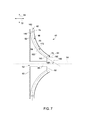
図7を参照すると一実施形態では、流路86が出口開口部84のところで斜め方向流れ経路190を画成するように、出口表面150が中央線軸54に対してある斜め方向角度188に配向される。この実施形態では流路86は、半径方向64に沿って流体を受け取り、斜め方向角度188で流体172を出口開口部84から排気するように構成される。
Referring to FIG. 7, in one embodiment, the
図8を参照すると一実施形態では、流路86が入口開口部82のところで斜め方向流れ経路194を画成するように、入口表面148が中央線軸54に対してある斜め方向角度192に配向される。この実施形態では流路86は、流体を入口出口開口部82から斜め方向角度192で受け取り、流体172を軸方向72に沿って出口開口部84を通り排気するように構成される。
Referring to FIG. 8, in one embodiment, the
図9を参照すると一実施形態では、上流側表面60は、下流側表面62の第2の半径方向幅68より小さな第1の半径方向幅66を含む。入口開口部82の第1の半径方向距離158は、出口開口部84の第2の半径方向距離160より短い。入口表面148は、軸方向72に延びる入口開口部82のところで流路86が軸方向流れ経路196を画成するように、中央線軸54に対して実質的に平行に配向される。出口表面150は、半径方向64に沿って延びる出口開口部84のところで流路86が半径方向流れ経路198を画成するように、中央線軸54に対して実質的に直角に配向される。移行表面152は、流路86を通り軸方向72から半径方向64に流体を導くように配向される。
With reference to FIG. 9, in one embodiment, the
図10を参照すると一実施形態では、出口表面150は、流路86が出口開口部84のところで斜め方向流れ経路202を画成するように中央線軸54に対してある斜め方向角度200に配向される。この実施形態では、流路86は、流体を軸方向72に沿って受け取り、流体172を出口開口部84から斜め方向角度202で排気するように構成される。
With reference to FIG. 10, in one embodiment, the
図11を参照すると一実施形態では、流路86が入口開口部82のところで斜め方向流れ経路190を画成するように、入口表面148が中央線軸54に対して斜め方向角度204に配向される。出口表面150は、出口開口部84のところで流路86が半径方向流れ経路198を画成するように、中央線軸54に対して実質的に直角に配向される。この実施形態では、流路86は、流体を入口開口部82から斜め方向角度204で受け取り、出口開口部84を通り半径方向64に沿って流体172を排気するように構成される。
Referring to FIG. 11, in one embodiment, the
図12を参照すると一実施形態では、流路86が入口開口部82のところで第1の斜め方向流れ経路208を画成するように、入口表面148が中央線軸54に対して第1の斜め方向角度206に配向される。出口表面150は、流路86が出口開口部84のところで第2の斜め方向流れ経路212を画成するように、中央線軸54に対して第2の斜め方向角度210に配向される。この実施形態では流路86は、入口出口開口部82から第1の斜め方向角度206で流体を受け取り、出口開口部84を通り第2の斜め方向角度210で流体172を排気するように構成される。
With reference to FIG. 12, in one embodiment, the
図13を参照すると一実施形態では、流路86が入口開口部82のところで第1の軸方向流れ経路214を画成するように、入口表面148が中央線軸54に対して実質的に平行に配向される。出口表面150は、流路86が出口開口部84のところで第2の軸方向流れ経路216を画成するように、中央線軸54に対して実質的に平行に配向される。この実施形態では流路86は、軸方向72に沿って流体172を受け取り、軸方向72に沿って流体172を排気するように構成される。
Referring to FIG. 13, in one embodiment, the
上記に記載される超音速圧縮機ロータは、流体を軸方向から半径方向に導く、または流体を半径方向から軸方向に導くためのコスト効率の高い、信頼性の高い方法を提供する。より具体的には、この超音速圧縮機ロータは、流路を通る流れ経路の向きを調節する移行表面を含む流路を含む。さらに、本明細書に記載されるこれらの実施形態は、入口表面と入口表面に対して平行でない出口表面とを含む超音速圧縮ロータを含む。その上、流体を軸方向から半径方向に導く流路を有する超音速圧縮機ロータを提供することによって、超音速圧縮機システムを軸方向吸気配向、半径方向吸気配向、軸方向排気配向、および/または半径方向排気配向の各々を含むように設計するのがこの超音速圧縮機ロータによって可能になる。結果として、本明細書に記載される超音速圧縮機ロータは、既知の超音速圧縮機アセンブリの流れ経路配向の限界を克服する。したがって、超音速圧縮機システムの製造および保守のコストを減少させることができる。 The supersonic compressor rotor described above provides a cost-effective and reliable method for directing fluid from axial to radial or directing fluid from radial to axial. More specifically, the supersonic compressor rotor includes a flow path that includes a transition surface that adjusts the orientation of the flow path through the flow path. Further, these embodiments described herein include a supersonic compression rotor that includes an inlet surface and an outlet surface that is not parallel to the inlet surface. Moreover, by providing a supersonic compressor rotor having a flow path that directs fluid from axial to radial direction, the supersonic compressor system can be made to have an axial intake orientation, a radial intake orientation, an axial exhaust orientation, and / or Alternatively, the supersonic compressor rotor can be designed to include each of the radial exhaust orientations. As a result, the supersonic compressor rotor described herein overcomes the flow path orientation limitations of known supersonic compressor assemblies. Thus, manufacturing and maintenance costs for the supersonic compressor system can be reduced.
超音速圧縮機ロータを組み立てるためのシステムおよび方法の例示的な実施形態が上記に詳細に記載されている。このシステムおよび方法は、本明細書に記載される特定の実施形態に限定されず、そうではなく、これらのシステムの構成部品および/または方法のステップは、本明細書に記載される他の構成部品および/またはステップから独立に、別個に利用することができる。例えば、これらのシステムおよび方法は、他の回転エンジンシステムおよび方法との組み合わせで使用することもでき、本明細書に記載されるような超音速圧縮機システムと共にのみ実施することに限定されない。そうではなく、この例示的な実施形態は、多くの他の回転システム用途と一緒に実施し、利用することができる。 Exemplary embodiments of systems and methods for assembling a supersonic compressor rotor are described in detail above. The systems and methods are not limited to the specific embodiments described herein; rather, the components and / or method steps of these systems are not limited to the other configurations described herein. It can be used separately and independently of the parts and / or steps. For example, these systems and methods can be used in combination with other rotary engine systems and methods, and are not limited to implementation only with a supersonic compressor system as described herein. Rather, this exemplary embodiment can be implemented and utilized with many other rotating system applications.
本発明の様々な実施形態の特定の機構がいくつかの図面に示され、他の図面に示されていない場合があるが、これは便宜上のためのみである。さらに、上記の記載での「1つの実施形態(one embodiment)」に対する参照は、記載された機構をやはり組み込む追加の実施形態の存在を除外するとして解釈すべきであることを意図していない。本発明の原理によれば、図面の任意の機構を、任意の他の図面の任意の機構と組み合わせて参照し、かつ/または特許請求することができる。 Although specific features of various embodiments of the invention may be shown in some drawings and not in others, this is for convenience only. Furthermore, references to “one embodiment” in the above description are not intended to be interpreted as excluding the existence of additional embodiments that also incorporate the described mechanisms. In accordance with the principles of the invention, any feature of a drawing may be referenced and / or claimed in combination with any feature of any other drawing.
本書では、例を使用し、最良の形態を含めて本発明を開示し、また任意のデバイスまたはシステムを作り、使用し、任意の組み込まれた方法を使用することを含めて、当業者が本発明を実施することを可能にしている。本発明の特許性のある範囲は特許請求の範囲によって定義され、当業者に思い浮かぶ他の実施例を含むことができる。そのような他の実施例は、それらが特許請求の範囲の文字通りの用語から異ならない構造的な要素である場合、またはそれらが特許請求の範囲の文字通りの用語からわずかしか異ならない等価な構造的要素を含む場合、特許請求の範囲の範囲内にあるものとする。 This document uses examples to disclose the invention, including the best mode, and to make and use any device or system and use any built-in method. Making it possible to carry out the invention. The patentable scope of the invention is defined by the claims, and may include other examples that occur to those skilled in the art. Such other embodiments are equivalent structural elements where they are structural elements that do not differ from the literal terms of the claims, or where they are only slightly different from the literal terms of the claims. Including elements is intended to be within the scope of the claims.
10 超音速圧縮機システム
12 吸気セクション
14 圧縮機セクション
16 排気セクション
18 駆動アセンブリ
20 ロータアセンブリ
22 駆動シャフト
24 圧縮機ハウジング
26 流体入口
28 流体出口
30 内側表面
32 空洞
34 流体源
36 入口ガイドベーンアセンブリ
38 入口ガイドベーン
40 超音速圧縮機ロータ
42 出口ガイドベーンアセンブリ
44 出力システム
46 ベーン
48 ロータディスク
50 ディスク本体
52 内側円筒状空洞
54 中央線軸
56 半径方向に内側の表面
58 半径方向外側表面
60 上流側表面
62 下流側表面
64 半径方向
66 第1の半径方向幅
68 第2の半径方向幅
70 距離
72 軸方向
74 上流側縁部
76 下流側縁部
80 対
82 入口開口部
84 出口開口部
86 流路
88 流れ経路
90 外側表面
92 内側表面
94 高さ
96 正圧面
98 負圧面
100 幅
102 横断面積
104 横断面積
106 横断面積
108 横断面積
110 超音速圧縮ランプ
112 圧縮波
114 スロート区域
116 圧縮表面
118 発散表面
120 前縁
122 後縁
124 斜め方向角度
126 圧縮区域
128 横断面積
130 第1の端部
132 第2の端部
134 斜め方向角度
136 発散区域
138 横断面積
140 シュラウドアセンブリ
142 シュラウドプレート
144 内側縁部
146 外側縁部
148 入口表面
150 出口表面
152 移行表面
154 入口平面
156 出口平面
158 第1の半径方向距離
160 第2の半径方向距離
162 半径方向流れ経路
164 軸方向流れ経路
166 移行流れ経路
168 矢印
170 矢印
172 流体
174 矢印
176 系統
178 第1の斜め方向衝撃波
180 第2の斜め方向衝撃波
182 垂直な衝撃波
184 系統
186 等エントロピー圧縮波
188 斜め方向角度
190 斜め方向流れ経路
192 斜め方向角度
194 斜め方向流れ経路
196 軸方向流れ経路
198 半径方向流れ経路
200 斜め方向角度
202 斜め方向角度
204 斜め方向角度
206 第1の斜め方向角度
208 第1の斜め方向流れ経路
210 第2の斜め方向角度
212 第2の斜め方向流れ経路
214 第1の軸方向流れ経路
216 第2の軸方向流れ経路
10 Supersonic Compressor System 12 Intake Section 14 Compressor Section 16 Exhaust Section 18 Drive Assembly 20 Rotor Assembly 22 Drive Shaft 24 Compressor Housing 26 Fluid Inlet 28 Fluid Outlet 30 Inner Surface 32 Cavity 34 Fluid Source 36 Inlet Guide Vane Assembly 38 Inlet Guide vane 40 Supersonic compressor rotor 42 Outlet guide vane assembly 44 Output system 46 Vane 48 Rotor disk 50 Disk body 52 Inner cylindrical cavity 54 Centerline axis 56 Radially inner surface 58 Radial outer surface 60 Upstream surface 62 Downstream Side surface 64 Radial direction 66 First radial width 68 Second radial width 70 Distance 72 Axial direction 74 Upstream edge 76 Downstream edge 80 to 82 Inlet opening 84 Outlet opening 86 Flow path 88 Flow path 90 Outer surface 92 Inner surface 94 Height 96 Pressure surface 98 Suction surface 100 Width 102 Transverse area 104 Transverse area 106 Transverse area 108 Transverse area 110 Supersonic compression ramp 112 Compression wave 114 Throat area 116 Compression surface 118 Diverging surface 120 Edge 122 Trailing edge 124 Diagonal angle 126 Compression zone 128 Transverse area 130 First end 132 Second end 134 Diagonal angle 136 Divergence zone 138 Transverse area 140 Shroud assembly 142 Shroud plate 144 Inner edge 146 Outer edge 148 Inlet surface 150 Outlet surface 152 Transition surface 154 Inlet plane 156 Outlet plane 158 First radial distance 160 Second radial distance 162 Radial flow path 164 Axial flow path 166 Transition flow path 168 Arrow 170 arrow 172 fluid 174 arrow 176 system 178 first oblique shock wave 180 second oblique shock wave 182 vertical shock wave 184 system 186 isentropic compression wave 188 oblique angle 190 oblique flow path 192 oblique angle 194 oblique flow Path 196 Axial flow path 198 Radial flow path 200 Oblique direction angle 202 Oblique direction angle 204 Oblique direction angle 206 First oblique direction angle 208 First oblique direction flow path 210 Second oblique direction angle 212 Second oblique Directional flow path 214 First axial flow path 216 Second axial flow path
Claims (10)
前記半径方向外側表面に連結される複数のベーンであって、隣接するベーンが、対を形成し、隣接するベーンの各前記対の間に流路が画成されるように配向され、前記流路が入口開口部と出口開口部の間を延び、前記入口表面が、前記入口開口部と前記移行表面の間を延びる入口平面を画成し、前記出口表面が、前記出口開口部と前記入口平面に対して平行でない前記移行表面との間を延びる出口平面を画成する、ベーンと、
前記流路内に少なくとも1つの圧縮波を形成するのを助けるように、前記流路内に配置され一様なスロートを画成する後縁を有する少なくとも1つの超音速圧縮ランプと、
を備える、超音速圧縮機ロータ。 A rotor disk comprising an upstream surface, a downstream surface, and a radially outer surface extending between the upstream surface and the downstream surface, wherein the radially outer surface is an inlet surface, an outlet surface; A rotor disk comprising a transition surface extending between the inlet surface and the outlet surface, the rotor disk defining a centerline axis;
A plurality of vanes coupled to the radially outer surface, wherein the adjacent vanes form a pair and are oriented such that a flow path is defined between each pair of adjacent vanes; A passage extends between the inlet opening and the outlet opening, the inlet surface defines an inlet plane extending between the inlet opening and the transition surface, and the outlet surface includes the outlet opening and the inlet. A vane defining an exit plane extending between the transition surface not parallel to the plane;
At least one supersonic compression ramp having a trailing edge disposed within the flow path to define a uniform throat so as to help form at least one compression wave within the flow path;
A supersonic compressor rotor.
前記ケーシング内に配置され、中央線軸を画成し、駆動アセンブリに回転可能に連結される駆動シャフトと、
前記駆動シャフトに連結され、流体を前記流体入口から前記流体出口まで導くために前記流体入口と前記流体出口の間に配置される超音速圧縮機ロータと
を備え、前記超音速圧縮機ロータが、
上流側表面と、下流側表面と、前記上流側表面と前記下流側表面の間を延びる半径方向外側表面とを備えるロータディスクであり、前記半径方向外側表面が、入口表面と、出口表面と、前記入口表面と前記出口表面の間を延びる移行表面とを備える、ロータディスクと、
前記半径方向外側表面に連結される複数のベーンであり、隣接するベーンが、対を形成し、隣接するベーンの各前記対の間に流路が画成されるように配向され、前記流路が入口開口部と出口開口部の間を延び、前記入口表面が、前記入口開口部と前記移行表面の間を延びる入口平面を画成し、前記出口表面が、前記出口開口部と前記入口平面に対して平行でない前記移行表面の間を延びる出口平面を画成する、複数のベーンと、
前記流路内に少なくとも1つの圧縮波を形成するのを助けるように前記流路内に配置され一様なスロートを画成する後縁を有する少なくとも1つの超音速圧縮ランプと、
を備える、超音速圧縮機システム。 A casing defining a cavity extending between the fluid inlet and the fluid outlet;
A drive shaft disposed within the casing, defining a central axis and rotatably coupled to the drive assembly;
A supersonic compressor rotor coupled to the drive shaft and disposed between the fluid inlet and the fluid outlet for directing fluid from the fluid inlet to the fluid outlet, the supersonic compressor rotor comprising:
A rotor disk comprising an upstream surface, a downstream surface, and a radially outer surface extending between the upstream surface and the downstream surface, the radially outer surface comprising an inlet surface, an outlet surface, A rotor disk comprising a transition surface extending between the inlet surface and the outlet surface;
A plurality of vanes coupled to the radially outer surface, wherein adjacent vanes form a pair, and a flow path is defined between each pair of adjacent vanes; Extending between the inlet opening and the outlet opening, the inlet surface defining an inlet plane extending between the inlet opening and the transition surface, the outlet surface being the outlet opening and the inlet plane. A plurality of vanes defining an exit plane extending between the transition surfaces that are not parallel to
At least one supersonic compression ramp having a trailing edge disposed within the flow path to define a uniform throat to help form at least one compression wave in the flow path;
A supersonic compressor system.
The inlet surface is oriented substantially parallel to the centerline axis such that the flow path defines an axial flow path from the inlet opening to the transition surface, and the outlet surface is The supersonic compressor system of claim 9, wherein a flow path is oriented at an oblique angle with respect to the central axis so as to define an oblique flow path from the transition surface to the outlet opening.
Applications Claiming Priority (2)
| Application Number | Priority Date | Filing Date | Title |
|---|---|---|---|
| US12/873,228 US8668446B2 (en) | 2010-08-31 | 2010-08-31 | Supersonic compressor rotor and method of assembling same |
| US12/873,228 | 2010-08-31 |
Publications (3)
| Publication Number | Publication Date |
|---|---|
| JP2012052534A JP2012052534A (en) | 2012-03-15 |
| JP2012052534A5 JP2012052534A5 (en) | 2014-10-02 |
| JP5920966B2 true JP5920966B2 (en) | 2016-05-24 |
Family
ID=44719295
Family Applications (1)
| Application Number | Title | Priority Date | Filing Date |
|---|---|---|---|
| JP2011181102A Active JP5920966B2 (en) | 2010-08-31 | 2011-08-23 | Supersonic compressor rotor and method of assembling it |
Country Status (5)
| Country | Link |
|---|---|
| US (1) | US8668446B2 (en) |
| EP (1) | EP2423511B1 (en) |
| JP (1) | JP5920966B2 (en) |
| CN (1) | CN102410249B (en) |
| RU (1) | RU2565253C2 (en) |
Families Citing this family (7)
| Publication number | Priority date | Publication date | Assignee | Title |
|---|---|---|---|---|
| JP5606515B2 (en) * | 2012-12-13 | 2014-10-15 | 三菱重工業株式会社 | Compressor |
| FR3007086B1 (en) * | 2013-06-18 | 2015-07-03 | Cryostar Sas | CENTRIFUGAL WHEEL |
| US9574567B2 (en) * | 2013-10-01 | 2017-02-21 | General Electric Company | Supersonic compressor and associated method |
| US9909597B2 (en) | 2013-10-15 | 2018-03-06 | Dresser-Rand Company | Supersonic compressor with separator |
| JP6627175B2 (en) * | 2015-03-30 | 2020-01-08 | 三菱重工コンプレッサ株式会社 | Impeller and centrifugal compressor |
| CN105626579A (en) * | 2016-03-04 | 2016-06-01 | 大连海事大学 | Hollow-shaft ram-rotor based on shock wave compression technology |
| CN110500299B (en) * | 2019-08-23 | 2021-04-27 | 何备荒 | Supersonic ultrahigh pressure carbon dioxide compressor unit |
Family Cites Families (41)
| Publication number | Priority date | Publication date | Assignee | Title |
|---|---|---|---|---|
| GB695948A (en) * | 1949-12-12 | 1953-08-19 | Havilland Engine Co Ltd | Improvements in or relating to centrifugal gas compressors |
| US2925952A (en) | 1953-07-01 | 1960-02-23 | Maschf Augsburg Nuernberg Ag | Radial-flow-compressor |
| US2949224A (en) * | 1955-08-19 | 1960-08-16 | American Mach & Foundry | Supersonic centripetal compressor |
| US3059834A (en) * | 1957-02-21 | 1962-10-23 | Hausammann Werner | Turbo rotor |
| GB885661A (en) | 1959-06-19 | 1961-12-28 | Power Jets Res & Dev Ltd | Intakes for supersonic flow |
| FR2134886A5 (en) * | 1971-04-23 | 1972-12-08 | Onera (Off Nat Aerospatiale) | |
| US4408957A (en) * | 1972-02-22 | 1983-10-11 | General Motors Corporation | Supersonic blading |
| US4199296A (en) | 1974-09-03 | 1980-04-22 | Chair Rory S De | Gas turbine engines |
| US4012166A (en) | 1974-12-04 | 1977-03-15 | Deere & Company | Supersonic shock wave compressor diffuser with circular arc channels |
| US4463772A (en) | 1981-09-29 | 1984-08-07 | The Boeing Company | Flush inlet for supersonic aircraft |
| US4704861A (en) | 1984-05-15 | 1987-11-10 | A/S Kongsberg Vapenfabrikk | Apparatus for mounting, and for maintaining running clearance in, a double entry radial compressor |
| US4620679A (en) | 1984-08-02 | 1986-11-04 | United Technologies Corporation | Variable-geometry inlet |
| US4791784A (en) * | 1985-06-17 | 1988-12-20 | University Of Dayton | Internal bypass gas turbine engines with blade cooling |
| US5062766A (en) * | 1988-09-14 | 1991-11-05 | Hitachi, Ltd. | Turbo compressor |
| US5061154A (en) * | 1989-12-11 | 1991-10-29 | Allied-Signal Inc. | Radial turbine rotor with improved saddle life |
| US5228832A (en) * | 1990-03-14 | 1993-07-20 | Hitachi, Ltd. | Mixed flow compressor |
| US5236301A (en) * | 1991-12-23 | 1993-08-17 | Allied-Signal Inc. | Centrifugal compressor |
| US5525038A (en) | 1994-11-04 | 1996-06-11 | United Technologies Corporation | Rotor airfoils to control tip leakage flows |
| US5881758A (en) | 1996-03-28 | 1999-03-16 | The Boeing Company | Internal compression supersonic engine inlet |
| JP2003517525A (en) | 1998-02-26 | 2003-05-27 | アリソン・アドバンスト・ディベロップメント・カンパニー | Compressor end wall bleed system |
| DE19812624A1 (en) | 1998-03-23 | 1999-09-30 | Bmw Rolls Royce Gmbh | Rotor blade of an axial flow machine |
| US6338609B1 (en) | 2000-02-18 | 2002-01-15 | General Electric Company | Convex compressor casing |
| US6488469B1 (en) | 2000-10-06 | 2002-12-03 | Pratt & Whitney Canada Corp. | Mixed flow and centrifugal compressor for gas turbine engine |
| US7334990B2 (en) | 2002-01-29 | 2008-02-26 | Ramgen Power Systems, Inc. | Supersonic compressor |
| US20030210980A1 (en) * | 2002-01-29 | 2003-11-13 | Ramgen Power Systems, Inc. | Supersonic compressor |
| CA2382382A1 (en) | 2002-04-16 | 2003-10-16 | Universite De Sherbrooke | Continuous rotary motor powered by shockwave induced combustion |
| US7293955B2 (en) | 2002-09-26 | 2007-11-13 | Ramgen Power Systrms, Inc. | Supersonic gas compressor |
| WO2004029432A2 (en) * | 2002-09-26 | 2004-04-08 | Ramgen Power Systems, Inc. | Gas turbine power plant with supersonic gas compressor |
| WO2004029451A2 (en) * | 2002-09-26 | 2004-04-08 | Ramgen Power Systems, Inc. | Supersonic gas compressor |
| US7434400B2 (en) | 2002-09-26 | 2008-10-14 | Lawlor Shawn P | Gas turbine power plant with supersonic shock compression ramps |
| US6948306B1 (en) | 2002-12-24 | 2005-09-27 | The United States Of America As Represented By The Secretary Of The Navy | Apparatus and method of using supersonic combustion heater for hypersonic materials and propulsion testing |
| US7070388B2 (en) | 2004-02-26 | 2006-07-04 | United Technologies Corporation | Inducer with shrouded rotor for high speed applications |
| JP4545009B2 (en) * | 2004-03-23 | 2010-09-15 | 三菱重工業株式会社 | Centrifugal compressor |
| CN100406746C (en) * | 2004-03-23 | 2008-07-30 | 三菱重工业株式会社 | Centrifugal compressor and manufacturing method for impeller |
| DE102004036331A1 (en) * | 2004-07-27 | 2006-02-16 | Man Turbo Ag | Inflow housing for axial flow machines |
| US7866937B2 (en) * | 2007-03-30 | 2011-01-11 | Innovative Energy, Inc. | Method of pumping gaseous matter via a supersonic centrifugal pump |
| US8960596B2 (en) | 2007-08-20 | 2015-02-24 | Kevin Kremeyer | Energy-deposition systems, equipment and method for modifying and controlling shock waves and supersonic flow |
| US8393158B2 (en) | 2007-10-24 | 2013-03-12 | Gulfstream Aerospace Corporation | Low shock strength inlet |
| WO2009092046A1 (en) * | 2008-01-18 | 2009-07-23 | Ramgen Power Systems, Llc | Method and apparatus for starting supersonic compressors |
| WO2010008407A1 (en) | 2008-07-14 | 2010-01-21 | Tenoroc Llc | Aerodynamic separation nozzle |
| US8137054B2 (en) * | 2008-12-23 | 2012-03-20 | General Electric Company | Supersonic compressor |
-
2010
- 2010-08-31 US US12/873,228 patent/US8668446B2/en active Active
-
2011
- 2011-08-23 JP JP2011181102A patent/JP5920966B2/en active Active
- 2011-08-25 EP EP11178782.6A patent/EP2423511B1/en active Active
- 2011-08-30 RU RU2011135908/06A patent/RU2565253C2/en active
- 2011-08-31 CN CN201110268661.9A patent/CN102410249B/en active Active
Also Published As
| Publication number | Publication date |
|---|---|
| RU2011135908A (en) | 2013-03-10 |
| EP2423511A3 (en) | 2014-08-27 |
| CN102410249B (en) | 2017-06-09 |
| EP2423511B1 (en) | 2018-05-30 |
| JP2012052534A (en) | 2012-03-15 |
| CN102410249A (en) | 2012-04-11 |
| US8668446B2 (en) | 2014-03-11 |
| US20120051933A1 (en) | 2012-03-01 |
| RU2565253C2 (en) | 2015-10-20 |
| EP2423511A2 (en) | 2012-02-29 |
Similar Documents
| Publication | Publication Date | Title |
|---|---|---|
| JP5920966B2 (en) | Supersonic compressor rotor and method of assembling it | |
| EP2863032B1 (en) | Centrifugal compressor | |
| RU2591750C2 (en) | Supersonic compressor unit (versions) and method for assembly thereof | |
| JP6128230B2 (en) | Centrifugal compressor and turbocharger | |
| CN102705266A (en) | Compressor device | |
| EP2466146B1 (en) | Supersonic compressor and method of assembling same | |
| US11047256B2 (en) | Variable nozzle unit and turbocharger | |
| JP6014337B2 (en) | System and method for assembling a supersonic compressor rotor including a radial flow path | |
| JP2018135836A (en) | Centrifugal compressor | |
| JP6088134B2 (en) | Supersonic compressor rotor and its assembly method | |
| JP2016108994A (en) | Compressor impeller, centrifugal compressor, and supercharger | |
| US11047393B1 (en) | Multi-stage centrifugal compressor, casing, and return vane | |
| US9574567B2 (en) | Supersonic compressor and associated method | |
| KR20150114499A (en) | An elliptical compressor cover for a turbocharger |
Legal Events
| Date | Code | Title | Description |
|---|---|---|---|
| A521 | Request for written amendment filed |
Free format text: JAPANESE INTERMEDIATE CODE: A523 Effective date: 20140818 |
|
| A621 | Written request for application examination |
Free format text: JAPANESE INTERMEDIATE CODE: A621 Effective date: 20140818 |
|
| A131 | Notification of reasons for refusal |
Free format text: JAPANESE INTERMEDIATE CODE: A131 Effective date: 20150707 |
|
| A521 | Request for written amendment filed |
Free format text: JAPANESE INTERMEDIATE CODE: A523 Effective date: 20151001 |
|
| TRDD | Decision of grant or rejection written | ||
| A01 | Written decision to grant a patent or to grant a registration (utility model) |
Free format text: JAPANESE INTERMEDIATE CODE: A01 Effective date: 20160315 |
|
| A61 | First payment of annual fees (during grant procedure) |
Free format text: JAPANESE INTERMEDIATE CODE: A61 Effective date: 20160408 |
|
| R150 | Certificate of patent or registration of utility model |
Ref document number: 5920966 Country of ref document: JP Free format text: JAPANESE INTERMEDIATE CODE: R150 |
|
| R250 | Receipt of annual fees |
Free format text: JAPANESE INTERMEDIATE CODE: R250 |
|
| R250 | Receipt of annual fees |
Free format text: JAPANESE INTERMEDIATE CODE: R250 |
|
| R250 | Receipt of annual fees |
Free format text: JAPANESE INTERMEDIATE CODE: R250 |
|
| R250 | Receipt of annual fees |
Free format text: JAPANESE INTERMEDIATE CODE: R250 |
|
| R250 | Receipt of annual fees |
Free format text: JAPANESE INTERMEDIATE CODE: R250 |
|
| R250 | Receipt of annual fees |
Free format text: JAPANESE INTERMEDIATE CODE: R250 |