JP5920909B2 - Pwm制御により双方向サーボアクチュエータを制御するためのシステム、方法、及び装置 - Google Patents
Pwm制御により双方向サーボアクチュエータを制御するためのシステム、方法、及び装置 Download PDFInfo
- Publication number
- JP5920909B2 JP5920909B2 JP2011113450A JP2011113450A JP5920909B2 JP 5920909 B2 JP5920909 B2 JP 5920909B2 JP 2011113450 A JP2011113450 A JP 2011113450A JP 2011113450 A JP2011113450 A JP 2011113450A JP 5920909 B2 JP5920909 B2 JP 5920909B2
- Authority
- JP
- Japan
- Prior art keywords
- current
- switching device
- actuator
- feedback
- current path
- Prior art date
- Legal status (The legal status is an assumption and is not a legal conclusion. Google has not performed a legal analysis and makes no representation as to the accuracy of the status listed.)
- Active
Links
- 238000000034 method Methods 0.000 title claims description 70
- 230000005284 excitation Effects 0.000 claims description 73
- 230000002457 bidirectional effect Effects 0.000 claims description 20
- 238000004804 winding Methods 0.000 claims description 9
- 230000008878 coupling Effects 0.000 claims description 3
- 238000010168 coupling process Methods 0.000 claims description 3
- 238000005859 coupling reaction Methods 0.000 claims description 3
- 238000010586 diagram Methods 0.000 description 27
- 239000003990 capacitor Substances 0.000 description 18
- 230000006870 function Effects 0.000 description 15
- 238000001914 filtration Methods 0.000 description 8
- 230000004044 response Effects 0.000 description 8
- 238000004590 computer program Methods 0.000 description 4
- 230000017525 heat dissipation Effects 0.000 description 4
- 238000012545 processing Methods 0.000 description 4
- 238000004891 communication Methods 0.000 description 3
- 230000000694 effects Effects 0.000 description 3
- 230000005669 field effect Effects 0.000 description 3
- 238000013459 approach Methods 0.000 description 2
- 230000008901 benefit Effects 0.000 description 2
- 230000009977 dual effect Effects 0.000 description 2
- 239000012530 fluid Substances 0.000 description 2
- 239000000446 fuel Substances 0.000 description 2
- 230000007246 mechanism Effects 0.000 description 2
- 229910044991 metal oxide Inorganic materials 0.000 description 2
- 150000004706 metal oxides Chemical class 0.000 description 2
- 230000008569 process Effects 0.000 description 2
- 239000004065 semiconductor Substances 0.000 description 2
- 230000005355 Hall effect Effects 0.000 description 1
- 230000003321 amplification Effects 0.000 description 1
- 239000000872 buffer Substances 0.000 description 1
- 230000001413 cellular effect Effects 0.000 description 1
- 230000001143 conditioned effect Effects 0.000 description 1
- 230000003750 conditioning effect Effects 0.000 description 1
- 238000005516 engineering process Methods 0.000 description 1
- 230000007613 environmental effect Effects 0.000 description 1
- 238000010438 heat treatment Methods 0.000 description 1
- 239000010720 hydraulic oil Substances 0.000 description 1
- -1 inductors Substances 0.000 description 1
- 230000003993 interaction Effects 0.000 description 1
- 238000004519 manufacturing process Methods 0.000 description 1
- 238000012986 modification Methods 0.000 description 1
- 230000004048 modification Effects 0.000 description 1
- 238000012544 monitoring process Methods 0.000 description 1
- 238000003199 nucleic acid amplification method Methods 0.000 description 1
- 239000007787 solid Substances 0.000 description 1
- 230000036962 time dependent Effects 0.000 description 1
Images


Classifications
-
- G—PHYSICS
- G05—CONTROLLING; REGULATING
- G05B—CONTROL OR REGULATING SYSTEMS IN GENERAL; FUNCTIONAL ELEMENTS OF SUCH SYSTEMS; MONITORING OR TESTING ARRANGEMENTS FOR SUCH SYSTEMS OR ELEMENTS
- G05B11/00—Automatic controllers
- G05B11/01—Automatic controllers electric
Landscapes
- Physics & Mathematics (AREA)
- General Physics & Mathematics (AREA)
- Engineering & Computer Science (AREA)
- Automation & Control Theory (AREA)
- Control Of Turbines (AREA)
- Feedback Control In General (AREA)
- Control Of Direct Current Motors (AREA)
- Control Of Electric Motors In General (AREA)
- Control Of Linear Motors (AREA)
- Amplifiers (AREA)
- Electronic Switches (AREA)
- Control Of Motors That Do Not Use Commutators (AREA)
Description
102 コントローラ
104 メモリ
106 プロセッサ(複数可)
108 入力/出力インターフェース(複数可)
110 ネットワークインターフェース(複数可)
112 オペレーティングシステム
114 データ
118 アクチュエータコマンド及び感知モジュール
120 励磁駆動及びアクチュエータ位置感知モジュール
121 アクチュエータ駆動及び感知回路
123 励磁駆動及びアクチュエータ位置感知回路
124 アクチュエータスイッチング増幅器
126 フィルタリング
128 アクチュエータ
130 感知及びフィードバック条件調整
132 アナログ/デジタルコンバータ(電圧制御発振器であってもよい)
134 励磁駆動スイッチング増幅器
136 位置センサ(LVTD/RVDT)
140 感知及びフィードバック条件調整
142 アナログ/デジタルコンバータ(電圧制御発振器であってもよい)
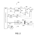
200 アクチュエータ駆動及び位置センサ励磁回路
202 コントローラ/マイクロプロセッサ
204 アクチュエータ参照又はパルス幅変調信号
206 極性信号
207 スイッチト駆動信号
208 スイッチング電力増幅器
209 フィルタ
210 第1のフィルタインダクタ
212 第2のフィルタインダクタ
214 フィルタキャパシタ
215 アクチュエータ電流
216 アクチュエータ
218 電流感知抵抗器
220 フィードバック回路
221 電流フィードバック(第2のフィードバック)
222 A/Dコンバータ
223 デジタル信号
224 位置センサ可動芯
226 位置センサ(LVDT、RVDT)
228 スイッチト励磁信号
230 スイッチング電力増幅器
232 励磁基準信号
234 フィードバック回路
236 励磁信号フィードバック
240 A/Dコンバータ
241 デジタル信号
300 位置決め制御システム
302 サーボ位置制御
304 デジタルサーボ位置調節器(マイクロプロセッサ)
306 アナログ/デジタルコンバータ
308 位置センサフィードバック条件調整
310 電流調節器
312 アクチュエータ用電流ドライバ
314 励磁制御
316 励磁ドライバ
318 アクチュエータ
320 位置センサ1(LVDT1)
322 位置センサ2(LVDT2)
324 弁アセンブリ
400 ミステリシース制御機能を有するスイッチングサーボアクチュエータ回路
401 出力ドライバ電流
402 基準信号
403 調整されたフィードバック信号
404 第1の演算増幅器
406 出力ドライバゲート抵抗器
408 電源
410 電流制御デバイス(出力ドライバ(MOSFET又は同様のものでよい))
412 感知抵抗器
413 フィードバック信号駆動電流感知信号
414 第1のフィードバック抵抗器
416 第2のフィードバック抵抗器
418 負荷
420 フィルタキャパシタ
422 バイアス抵抗器
424 利得抵抗器
428 フィードバック遅延抵抗器
430 フィードバック遅延キャパシタ
432 グランド
500 双方向電流スイッチング回路
502 第1のスイッチ制御信号(PWM基準信号)
504 第1の電流フィードバック信号
506 第1の演算増幅器
508 第1のスイッチングデバイス
509 Vcc(正電圧電源)
510 感知抵抗器
511 グランド
512 負荷とフィルタ
514 第1の差動増幅器
516 第1のフィルタ抵抗器
518 第1のフィルタキャパシタ
520 第2のスイッチ制御信号(PWM基準信号)
522 第2の電流フィードバック信号
524 第2の演算増幅器
526 第2のスイッチングデバイス
527 −Vee(負電圧電源)
528 第2の差動増幅器
530 第2のフィルタ抵抗器
532 第2のフィルタキャパシタ
534 正電流経路
536 負電流経路
538 正の電流
540 負の電流
600 Hブリッジ
602 電源
604 第1のスイッチ駆動信号
606 第2のスイッチ駆動信号
608 方向/極性信号
609 インバータ
610 第1のスイッチングデバイス
612 第3のスイッチングデバイス
614 第2のスイッチングデバイス
616 第4のスイッチングデバイス
617 負駆動電流
618 負荷
619 正駆動電流
620 正電流経路
622 負電流経路
700 正の電流スイッチ状態
702 第1のスイッチングデバイス状態
704 第2のスイッチングデバイス状態(常時オン)
706 従来のHブリッジアームの第2のスイッチングデバイス状態(比較のため)
800 負の電流スイッチ状態
802 第2の負のスイッチングデバイス状態(常時オン)
804 第1の負のスイッチングデバイス状態
806 従来のHブリッジアームの第2のスイッチングデバイス状態(比較のため)
900 方法
902 ブロック
904 ブロック
906 ブロック
908 ブロック
910 ブロック
1000 方法
1002 ブロック
1004 ブロック
1006 ブロック
1008 ブロック
1010 ブロック
1100 方法
1102 ブロック
1104 ブロック
1106 ブロック
1108 ブロック
1200 方法
1202 ブロック
1204 ブロック
1206 ブロック
1208 ブロック
Claims (10)
- アクチュエータを通る双方向駆動電流を制御するための方法であって、
方向制御信号(502、520、608)を受信するステップと、
前記方向制御信号(502、520、608)を受信することに少なくとも部分的に基づいてアクチュエータ(512、618)を通る少なくとも1つのスイッチング可能な正(534、620)電流経路及び少なくとも1つのスイッチング可能な負(536、622)電流経路を確立するように1つ又は複数のデバイス(508、526、610、612、614、616)を操作するステップと、
交流スイッチト励磁信号(228)を生成し、前記アクチュエータ(512、618)に少なくとも間接的に接続された位置センサの励磁巻線を介して送るステップと、
前記スイッチト励磁信号(228)を、前記位置センサに関連付けられた感知巻線に結合するステップと、
前記アクチュエータ(512、618)又は前記結合されたスイッチト励磁信号(228)に関連付けられた電流(538、540、617、619)に少なくとも基づいて電流フィードバック(504、522)又は励磁信号フィードバック(236)を送るステップと、
前記電流フィードバック(504、522)又は励磁信号フィードバック(236)に少なくとも部分的に基づいて前記電流(538、540、617、619)をヒステリシスPWM制御するステップと
を含み、
前記正電流経路(620)が、第1のスイッチングデバイス(610)及び第4のスイッチングデバイス(616)を含み、
前記電流(617、619)をヒステリシスPWM制御するステップが、
前記第1のスイッチングデバイス(610)が前記電流を制御するステップと、
前記第1のスイッチングデバイス(610)が前記電流を制御する間に、前記第4のスイッチングデバイス(616)が常時「ON」にするステップと、
を含む、
方法。 - 前記電流(538、540、617、619)をヒステリシスPWM制御するステップが、前記電流フィードバック(504、522)又は前記励磁信号フィードバック(236)とパルス幅変調信号(502、520)との比較結果にさらに基づく請求項1記載の方法。
- 前記負電流経路(622)が、第2のスイッチングデバイス(614)及び第3のスイッチングデバイス(612)を含み、
前記電流(617、619)をヒステリシスPWM制御するステップが、第1のスイッチングデバイス(610)及び第4のスイッチングデバイス(616)が開成状態にあり、前記第2のスイッチングデバイス(614)がパルス幅変調に少なくとも部分的に基づいて前記電流を制御する間に、前記第3のスイッチングデバイス(612)を常時「ON」とするステップを含む、請求項1または2に記載の方法。 - 前記負電流経路(622)が、第2のスイッチングデバイス(614)及び第3のスイッチングデバイス(612)を含み、
少なくとも1つの正電流経路(534)又は少なくとも1つの負電流経路(536)を確立するように1つ又は複数のデバイス(508、526)を操作するステップが、少なくとも前記第1及び第2のスイッチングデバイス(610、614)を調整することを含み、前記前記第1及び第2のスイッチングデバイス(610、614)のうちの少なくとも1つが常に開成状態にある請求項1乃至3のいずれかに記載の方法。 - 前記電流(538、540、617、619)をヒステリシスPWM制御するステップが、少なくとも1つの正電流経路(534、620)又は少なくとも1つの負電流経路(536、622)に関連付けられた少なくとも1つのスイッチ(508、526、610、612、614、616)を制御することを含む請求項1乃至4のいずれかに記載の方法。
- 前記電流(538、540、617、619)をヒステリシスPWM制御するステップが、パルス幅変調を使用して前記第4のスイッチングデバイス(616)を制御することを含む請求項1乃至5のいずれかに記載の方法。
- 前記アクチュエータ(512、618)がタービンに配置された弁に関連するアクチュエータであり、
少なくとも1つの正電流経路(534、620)又は少なくとも1つの負電流経路(536、622)を確立するように1つ又は複数のデバイス(508、526、610、612、614、616)を操作するステップが、2つの相互排他的な電流経路(534、536:620、622)をアクチュエータ(512、618)と接続することを含む請求項1乃至6のいずれかに記載の方法。 - 双方向駆動電流(538、540、617、619)を制御するためのシステムであって、
アクチュエータ(618)と、
励磁巻線及び感知巻線を含む位置センサと、
少なくとも1つの電源(509、527、602)と、
前記アクチュエータ(618)を通る少なくとも1つの正電流経路(534、620)及び少なくとも1つの負電流経路(536、622)と、
コントローラ(102)と
を備え、
前記コントローラが、
交流スイッチト励磁信号(228)を生成し、前記アクチュエータの位置に比例する信号強度と共に前記感知巻線に結合される該交流スイッチト励磁信号(228)を前記位置センサの前記励磁巻線を介して送るステップと、
前記アクチュエータ(512、618)又は前記結合されたスイッチト励磁信号(228)に関連付けられた電流(538、540、617、619)に少なくとも基づいて電流フィードバック(504、522)又は励磁信号フィードバック(236)を送るステップと、
前記電流フィードバック(504、522)又は励磁信号フィードバック(236)に少なくとも部分的に基づいて前記電流経路(534、536、620、622)を操作し、電流(538、540、617、619)をヒステリシスPWM制御するように構成されており、
前記正電流経路(620)が、第1のスイッチングデバイス(610)及び第4のスイッチングデバイス(616)を含み、前記第1のスイッチングデバイス(610)がパルス幅変調に少なくとも部分的に基づいて前記電流を制御する間に、前記第4のスイッチングデバイス(616)が常時「ON」となる、
ことを特徴とする、システム。 - 前記アクチュエータ(512、618)がタービンに配置された弁に関連するアクチュエータであり、
前記コントローラ(102)が、前記電流フィードバック(504、522)又は前記励磁信号フィードバック(236)とパルス幅変調信号(502、520)との比較結果に基づいて前記電流経路(534、536、620、622)を操作し、電流(617、619)をヒステリシスPWM制御するようにさらに構成される請求項8記載のシステム。 - 前記負電流経路(622)が、第2のスイッチングデバイス(614)及び第3のスイッチングデバイス(612)を含み、前記第2のスイッチングデバイス(614)がパルス幅変調に少なくとも部分的に基づいて前記電流を制御する間に、前記第3のスイッチングデバイス(612)が常時「ON」となる、
請求項8または9に記載のシステム。
Applications Claiming Priority (2)
| Application Number | Priority Date | Filing Date | Title |
|---|---|---|---|
| US12/784,657 | 2010-05-21 | ||
| US12/784,657 US8064158B1 (en) | 2010-05-21 | 2010-05-21 | Systems, methods, and apparatus for controlling Bi-directional servo actuator with PWM control |
Publications (3)
| Publication Number | Publication Date |
|---|---|
| JP2011258192A JP2011258192A (ja) | 2011-12-22 |
| JP2011258192A5 JP2011258192A5 (ja) | 2014-06-26 |
| JP5920909B2 true JP5920909B2 (ja) | 2016-05-18 |
Family
ID=44484887
Family Applications (1)
| Application Number | Title | Priority Date | Filing Date |
|---|---|---|---|
| JP2011113450A Active JP5920909B2 (ja) | 2010-05-21 | 2011-05-20 | Pwm制御により双方向サーボアクチュエータを制御するためのシステム、方法、及び装置 |
Country Status (4)
| Country | Link |
|---|---|
| US (1) | US8064158B1 (ja) |
| EP (1) | EP2388662A3 (ja) |
| JP (1) | JP5920909B2 (ja) |
| CN (1) | CN102352781B (ja) |
Families Citing this family (20)
| Publication number | Priority date | Publication date | Assignee | Title |
|---|---|---|---|---|
| US20110285367A1 (en) * | 2010-05-21 | 2011-11-24 | General Electric Company | Systems, methods, and apparatus for controlling bi-directional servo actuator using an h-bridge with hysteresis control |
| GB2482134B (en) * | 2010-07-20 | 2015-12-02 | Gm Global Tech Operations Inc | A method for operating an electromechanical actuator |
| US20130283762A1 (en) * | 2012-04-27 | 2013-10-31 | General Electric Company | Rotary vane actuator operated air valves |
| US9355672B2 (en) * | 2014-05-23 | 2016-05-31 | Texas Instruments Incorporated | Disk drive preamplifier R/C differential mode filter of power supply |
| FR3022091A1 (fr) * | 2014-10-10 | 2015-12-11 | Continental Automotive France | Procede et dispositif de commande d'une charge par un pont en h |
| US9958838B2 (en) | 2014-10-23 | 2018-05-01 | Halliburton Energy Services, Inc. | Optimizing power delivered to an electrical actuator |
| US10151216B2 (en) | 2016-08-31 | 2018-12-11 | General Electric Technology Gmbh | Insulation quality indicator module for a valve and actuator monitoring system |
| US10871081B2 (en) | 2016-08-31 | 2020-12-22 | General Electric Technology Gmbh | Creep damage indicator module for a valve and actuator monitoring system |
| US10544700B2 (en) | 2016-08-31 | 2020-01-28 | General Electric Technology Gmbh | Advanced startup counter module for a valve and actuator monitoring system |
| US10626749B2 (en) | 2016-08-31 | 2020-04-21 | General Electric Technology Gmbh | Spindle vibration evaluation module for a valve and actuator monitoring system |
| US10156153B2 (en) | 2016-08-31 | 2018-12-18 | General Electric Technology Gmbh | Advanced tightness test evaluation module for a valve and actuator monitoring system |
| US10066501B2 (en) | 2016-08-31 | 2018-09-04 | General Electric Technology Gmbh | Solid particle erosion indicator module for a valve and actuator monitoring system |
| US10233786B2 (en) | 2017-03-28 | 2019-03-19 | General Electric Technology Gmbh | Actuator spring lifetime supervision module for a valve and actuator monitoring system |
| US10935585B2 (en) * | 2018-11-19 | 2021-03-02 | Sigmasense, Llc. | Drive sense circuit with transient suppression |
| US10671034B1 (en) | 2019-03-18 | 2020-06-02 | Sigmasense, Llc. | Motor drive input adaptation with in-line drive-sense circuit |
| US11061082B2 (en) | 2019-03-18 | 2021-07-13 | Sigmasense, Llc. | Single line hall effect sensor drive and sense |
| US11251802B1 (en) | 2020-08-03 | 2022-02-15 | xMEMS Labs, Inc. | Nonlinear digital-to-analog converter |
| US11271480B2 (en) * | 2020-08-03 | 2022-03-08 | xMEMS Labs, Inc. | Driving circuit with energy recycle capability and method thereof |
| US11996866B2 (en) | 2022-03-21 | 2024-05-28 | xMEMS Labs, Inc. | Feedback control system achieving high performance via density modulation |
| CN119781284B (zh) * | 2024-11-29 | 2025-10-28 | 中国航发西安动力控制科技有限公司 | 一种燃油调节器的控制模型辨识装置 |
Family Cites Families (15)
| Publication number | Priority date | Publication date | Assignee | Title |
|---|---|---|---|---|
| JPH02125598U (ja) * | 1989-03-28 | 1990-10-16 | ||
| US5305215A (en) * | 1991-05-15 | 1994-04-19 | Phoenix International Corporation | Expandable, mobile, modular microcomputer system for an off-road vehicle |
| DK0732004T3 (da) * | 1993-11-30 | 1999-02-15 | Crown Int | Switch-mode-strømforsyning til en effektforstærker |
| US5568528A (en) | 1994-11-21 | 1996-10-22 | Westinghouse Electric Corporation | Method and system for compensating a rod position indication system for non-linearity |
| JP2864474B2 (ja) * | 1995-11-27 | 1999-03-03 | 本田技研工業株式会社 | 電動パワーステアリング装置 |
| US5838515A (en) * | 1996-04-30 | 1998-11-17 | Quantum Corporation | PWM/linear driver for disk drive voice coil actuator |
| JPH09297602A (ja) * | 1996-05-01 | 1997-11-18 | Kenji Masuda | 電気油圧サーボ弁装置 |
| US6208497B1 (en) * | 1997-06-26 | 2001-03-27 | Venture Scientifics, Llc | System and method for servo control of nonlinear electromagnetic actuators |
| AU2001277128A1 (en) | 2000-07-24 | 2002-02-05 | Hamilton Sundstrand Corporation | Apparatus for ac-to-dc conversion which provides a signed dc signal |
| JP2003300473A (ja) * | 2002-04-10 | 2003-10-21 | Nsk Ltd | 電動パワーステアリング装置 |
| US6836032B2 (en) | 2002-11-14 | 2004-12-28 | Levram Medical Systems, Ltd. | Electromagnetic moving-coil device |
| JP3942583B2 (ja) | 2003-11-21 | 2007-07-11 | 松下電器産業株式会社 | ドライバ回路 |
| US6981381B1 (en) * | 2003-12-16 | 2006-01-03 | Lattice Semiconductor Corp. | Linear thermoelectric device driver |
| US6947824B1 (en) * | 2004-06-22 | 2005-09-20 | General Motors Corporation | Engine RPM and torque control transition |
| JP2007263044A (ja) * | 2006-03-29 | 2007-10-11 | Aisin Seiki Co Ltd | 弁開閉制御装置 |
-
2010
- 2010-05-21 US US12/784,657 patent/US8064158B1/en active Active
-
2011
- 2011-05-19 EP EP11166788A patent/EP2388662A3/en not_active Ceased
- 2011-05-20 CN CN201110149044.7A patent/CN102352781B/zh active Active
- 2011-05-20 JP JP2011113450A patent/JP5920909B2/ja active Active
Also Published As
| Publication number | Publication date |
|---|---|
| JP2011258192A (ja) | 2011-12-22 |
| EP2388662A2 (en) | 2011-11-23 |
| US8064158B1 (en) | 2011-11-22 |
| CN102352781B (zh) | 2015-12-16 |
| EP2388662A3 (en) | 2012-08-29 |
| CN102352781A (zh) | 2012-02-15 |
| US20110285368A1 (en) | 2011-11-24 |
Similar Documents
| Publication | Publication Date | Title |
|---|---|---|
| JP5920909B2 (ja) | Pwm制御により双方向サーボアクチュエータを制御するためのシステム、方法、及び装置 | |
| JP2011248883A (ja) | Hブリッジをヒステリシス制御とともに使用して双方向サーボアクチュエータを制御するためのシステム、方法、及び装置 | |
| JP2011248881A (ja) | 高効率サーボアクチュエータ及び励磁ドライバを実現するためのシステム、方法、及び装置 | |
| CN107437916B (zh) | 长定子直线电动机定子的长定子直线电动机线圈的控制方法 | |
| US20080099090A1 (en) | Valve, controller, system and method providing closed loop current control of a voice coil using pulse width modulation drive elements | |
| CN102099755B (zh) | 电负载的仿真电路 | |
| US8044650B2 (en) | Methods and apparatus for current sensing in mutually coupled inductors | |
| US9319008B2 (en) | Differential output inductor for class D amplifier | |
| JP2011253532A (ja) | 双方向ヒステリシス制御を使用してアクチュエータ駆動電流を制御するためのシステム、方法、及び装置 | |
| US9237621B1 (en) | Current control circuit and method for floating IC driven buck-boost converter | |
| EP2000876B1 (en) | Low heat dissipation I/O module using direct drive buck converter | |
| JP5047280B2 (ja) | 圧電アクチュエータを有する装置 | |
| US20130268122A1 (en) | Systems, Methods, and Apparatus for Driving Servo Actuators | |
| Swathi et al. | Design of intelligent controller for reduction of chattering phenomenon in robotic arm: A rapid prototyping | |
| TWI435530B (zh) | 具有回授補償控制之通風裝置及其操作方法 | |
| CN107408885B (zh) | 直流-直流转换器 | |
| Ding et al. | A real-time sinusoidal voltage-adjustment power supply based on interleaved buck converters with enhanced reference-tracking capability | |
| JP2011041356A (ja) | モータ駆動装置 | |
| CN111033990A (zh) | 电力变换装置以及逆变器电路 | |
| JP6305061B2 (ja) | 設定変更可能なソレノイド発動方法及び装置 | |
| CN107023709A (zh) | 定位器 | |
| Thakare et al. | Speed control strategy of switched reluctance motor drive using asymmetric bridge converter topology | |
| CN115483831A (zh) | 多相电压调节器可变相计数稳定性 | |
| Olivier et al. | Improved linear model of self oscillating systems such as relay feedback current controllers | |
| Prasad et al. | Modeling and reliability analysis of three phase z-source AC-AC converter |
Legal Events
| Date | Code | Title | Description |
|---|---|---|---|
| A521 | Request for written amendment filed |
Free format text: JAPANESE INTERMEDIATE CODE: A523 Effective date: 20140512 |
|
| A621 | Written request for application examination |
Free format text: JAPANESE INTERMEDIATE CODE: A621 Effective date: 20140512 |
|
| A131 | Notification of reasons for refusal |
Free format text: JAPANESE INTERMEDIATE CODE: A131 Effective date: 20150224 |
|
| A977 | Report on retrieval |
Free format text: JAPANESE INTERMEDIATE CODE: A971007 Effective date: 20150227 |
|
| A521 | Request for written amendment filed |
Free format text: JAPANESE INTERMEDIATE CODE: A523 Effective date: 20150423 |
|
| A131 | Notification of reasons for refusal |
Free format text: JAPANESE INTERMEDIATE CODE: A131 Effective date: 20150804 |
|
| A601 | Written request for extension of time |
Free format text: JAPANESE INTERMEDIATE CODE: A601 Effective date: 20151102 |
|
| A521 | Request for written amendment filed |
Free format text: JAPANESE INTERMEDIATE CODE: A523 Effective date: 20151127 |
|
| TRDD | Decision of grant or rejection written | ||
| A01 | Written decision to grant a patent or to grant a registration (utility model) |
Free format text: JAPANESE INTERMEDIATE CODE: A01 Effective date: 20160315 |
|
| A61 | First payment of annual fees (during grant procedure) |
Free format text: JAPANESE INTERMEDIATE CODE: A61 Effective date: 20160407 |
|
| R150 | Certificate of patent or registration of utility model |
Ref document number: 5920909 Country of ref document: JP Free format text: JAPANESE INTERMEDIATE CODE: R150 |
|
| R250 | Receipt of annual fees |
Free format text: JAPANESE INTERMEDIATE CODE: R250 |
|
| R250 | Receipt of annual fees |
Free format text: JAPANESE INTERMEDIATE CODE: R250 |
|
| R250 | Receipt of annual fees |
Free format text: JAPANESE INTERMEDIATE CODE: R250 |
|
| R250 | Receipt of annual fees |
Free format text: JAPANESE INTERMEDIATE CODE: R250 |
|
| R250 | Receipt of annual fees |
Free format text: JAPANESE INTERMEDIATE CODE: R250 |
|
| S111 | Request for change of ownership or part of ownership |
Free format text: JAPANESE INTERMEDIATE CODE: R313113 |
|
| R350 | Written notification of registration of transfer |
Free format text: JAPANESE INTERMEDIATE CODE: R350 |
|
| R250 | Receipt of annual fees |
Free format text: JAPANESE INTERMEDIATE CODE: R250 |
|
| R250 | Receipt of annual fees |
Free format text: JAPANESE INTERMEDIATE CODE: R250 |