JP5914929B2 - Mounting band for position sensor - Google Patents
Mounting band for position sensor Download PDFInfo
- Publication number
- JP5914929B2 JP5914929B2 JP2011198407A JP2011198407A JP5914929B2 JP 5914929 B2 JP5914929 B2 JP 5914929B2 JP 2011198407 A JP2011198407 A JP 2011198407A JP 2011198407 A JP2011198407 A JP 2011198407A JP 5914929 B2 JP5914929 B2 JP 5914929B2
- Authority
- JP
- Japan
- Prior art keywords
- band
- thin plate
- protrusions
- position sensor
- cylinder tube
- Prior art date
- Legal status (The legal status is an assumption and is not a legal conclusion. Google has not performed a legal analysis and makes no representation as to the accuracy of the status listed.)
- Active
Links
- 230000002093 peripheral effect Effects 0.000 claims description 19
- 239000012530 fluid Substances 0.000 description 12
- 238000004519 manufacturing process Methods 0.000 description 9
- 238000001514 detection method Methods 0.000 description 4
- 230000005389 magnetism Effects 0.000 description 3
- 239000002184 metal Substances 0.000 description 2
- 238000003491 array Methods 0.000 description 1
- 238000007599 discharging Methods 0.000 description 1
- 238000003780 insertion Methods 0.000 description 1
- 230000037431 insertion Effects 0.000 description 1
- 238000009434 installation Methods 0.000 description 1
- 230000007246 mechanism Effects 0.000 description 1
- 230000000087 stabilizing effect Effects 0.000 description 1
Images


Classifications
-
- G—PHYSICS
- G01—MEASURING; TESTING
- G01B—MEASURING LENGTH, THICKNESS OR SIMILAR LINEAR DIMENSIONS; MEASURING ANGLES; MEASURING AREAS; MEASURING IRREGULARITIES OF SURFACES OR CONTOURS
- G01B7/00—Measuring arrangements characterised by the use of electric or magnetic techniques
- G01B7/14—Measuring arrangements characterised by the use of electric or magnetic techniques for measuring distance or clearance between spaced objects or spaced apertures
-
- F—MECHANICAL ENGINEERING; LIGHTING; HEATING; WEAPONS; BLASTING
- F15—FLUID-PRESSURE ACTUATORS; HYDRAULICS OR PNEUMATICS IN GENERAL
- F15B—SYSTEMS ACTING BY MEANS OF FLUIDS IN GENERAL; FLUID-PRESSURE ACTUATORS, e.g. SERVOMOTORS; DETAILS OF FLUID-PRESSURE SYSTEMS, NOT OTHERWISE PROVIDED FOR
- F15B15/00—Fluid-actuated devices for displacing a member from one position to another; Gearing associated therewith
- F15B15/20—Other details, e.g. assembly with regulating devices
- F15B15/28—Means for indicating the position, e.g. end of stroke
- F15B15/2892—Means for indicating the position, e.g. end of stroke characterised by the attachment means
-
- F—MECHANICAL ENGINEERING; LIGHTING; HEATING; WEAPONS; BLASTING
- F15—FLUID-PRESSURE ACTUATORS; HYDRAULICS OR PNEUMATICS IN GENERAL
- F15B—SYSTEMS ACTING BY MEANS OF FLUIDS IN GENERAL; FLUID-PRESSURE ACTUATORS, e.g. SERVOMOTORS; DETAILS OF FLUID-PRESSURE SYSTEMS, NOT OTHERWISE PROVIDED FOR
- F15B15/00—Fluid-actuated devices for displacing a member from one position to another; Gearing associated therewith
-
- F—MECHANICAL ENGINEERING; LIGHTING; HEATING; WEAPONS; BLASTING
- F16—ENGINEERING ELEMENTS AND UNITS; GENERAL MEASURES FOR PRODUCING AND MAINTAINING EFFECTIVE FUNCTIONING OF MACHINES OR INSTALLATIONS; THERMAL INSULATION IN GENERAL
- F16B—DEVICES FOR FASTENING OR SECURING CONSTRUCTIONAL ELEMENTS OR MACHINE PARTS TOGETHER, e.g. NAILS, BOLTS, CIRCLIPS, CLAMPS, CLIPS OR WEDGES; JOINTS OR JOINTING
- F16B2/00—Friction-grip releasable fastenings
- F16B2/02—Clamps, i.e. with gripping action effected by positive means other than the inherent resistance to deformation of the material of the fastening
- F16B2/06—Clamps, i.e. with gripping action effected by positive means other than the inherent resistance to deformation of the material of the fastening external, i.e. with contracting action
- F16B2/08—Clamps, i.e. with gripping action effected by positive means other than the inherent resistance to deformation of the material of the fastening external, i.e. with contracting action using bands
Description
本発明は、流体圧シリンダ等のシリンダチューブ内をその軸線方向に摺動するピストンの動作位置を検出するための位置センサを、保持部材を介して該シリンダチューブに固定するための位置センサ用取付バンドに関するものである。 The present invention relates to a position sensor mounting for fixing a position sensor for detecting an operating position of a piston sliding in an axial direction in a cylinder tube such as a fluid pressure cylinder to the cylinder tube via a holding member. It is about the band.
流体圧シリンダにおいてピストンの動作位置を検出し、その検出信号を各種の制御用信号として使用する場合、位置検出装置が取り付けられる。この位置検出装置は、上記ピストンに取り付けた永久磁石の磁気を、シリンダチューブの外面に取り付けた磁気感応型の位置センサで検出するようにしたもので、該位置センサをシリンダチューブの外面に取り付けるため、従来より様々な機構が用いられている。 In the case where the operation position of the piston is detected in the fluid pressure cylinder and the detection signal is used as various control signals, a position detection device is attached. In this position detection device, the magnetism of a permanent magnet attached to the piston is detected by a magnetically sensitive position sensor attached to the outer surface of the cylinder tube, and the position sensor is attached to the outer surface of the cylinder tube. Various mechanisms are conventionally used.
図12及び図13は、上記位置センサ21が固定された既知の流体圧シリンダ30の一例及びそれに用いられる位置センサ用取付バンドを示すもので、該流体圧シリンダは、シリンダ孔を内部に有する円筒形をしたシリンダチューブ31と、該シリンダチューブ31内にその中心軸線Lに沿って摺動自在に収容されたピストン及びそれに連結されて外部に延出するピストンロッド33とを有している。そして、上記シリンダチューブ31の一方端に設けられているロッドカバー34のポート36aと、他方端のヘッド部35に設けられたポート36bとを通じて、上記ピストンの両側の圧力室に圧力流体(例えば、圧縮空気)を交互に給排することにより、該ピストンが前進或いは後退するものである。また、上記ピストンの外周にはリング状の永久磁石が取り付けられ、上記位置センサ21はこの永久磁石の磁気を検出することにより、上記ピストンの動作位置の検出信号を出力するようになっている。
FIGS. 12 and 13 show an example of a known
このような流体圧シリンダ30において、上記位置センサ21を保持する保持部材20をシリンダチューブ31の外周上の任意位置に設置するために用いられる位置センサ用取付バンド10は、通常、上記位置センサ21を保持する保持部材20を両側から挟持する相対する一対の挟持部11a,11bを、上記シリンダチューブ31の外周に巻着する薄板バンド13の両端に設けることにより構成し、上記挟持部11a,11bで上記位置センサ保持部材20を挟み、取付ねじ14をそれらに挿入して螺着している。
In such a
上記図13の位置センサ用取付バンド10は、シリンダチューブ31上を移動させることによって、位置センサ21の取付位置を自由に調整可能にしたものであるが、作業者らが不用意に該位置センサ用取付バンド10にある程度の力を作用させても該位置センサ21が動かないように、十分な固定力を有している必要がある。該位置センサ用取付バンド10の固定力とは、該位置センサ用取付バンド10に作用するシリンダチューブ31の円周方向及び軸方向の力に対する、該位置センサ用取付バンド10の固定時における最大の抗力の大きさである。
The position
上記位置センサ用取付バンド10においては、固定力を発生させるために取付ねじ14によって挟持部11a,11bを締め付けると、上記薄板バンド13に張力が生じ、これによって該薄板バンド13と上記シリンダチューブ31の当接面全体に分散した圧力分布ができ、この圧力分布によって上記位置センサ用取付バンド10に固定力が生じるが、この場合の固定力は、薄板バンド13とシリンダチューブ31の当接面全体に分散するために、必ずしも製品において必要となる固定力の大きさを上回るとは限らない。また、上記位置センサ用取付バンド10の固定力は、該位置センサ用取付バンド10の取付時における傾斜、或いは取付ねじ14を増し締めしたときに生じる該位置センサ用取付バンド10のねじれ等の状態変化による影響を受けやすく不安定になる。
In the position
上記固定力の増大を図るため、特許文献1に開示されているように、薄板バンドにゴムのライニングを施すことも知られている。該薄板バンドの内周面にゴム等の摩擦抵抗の大きなライニングを貼付すと、該位置センサ用取付バンド10の有する不安定さを解消して大きな固定力を得ることができるが、薄板バンドに均一な厚さで確実にゴムを貼付しておくのは困難であり、製造コストが高くなるという問題がある。また、薄板バンドを長期間一定の位置に固定していた場合、シリンダチューブ31へのゴムの固着により、該位置センサ用取付バンド10の位置調整が困難になる。
In order to increase the fixing force, as disclosed in Patent Document 1, it is also known to apply a rubber lining to a thin band. When a lining having a large frictional resistance such as rubber is applied to the inner peripheral surface of the thin plate band, the instability of the position
更に、上記ライニングを貼付した位置センサ用取付バンド10は、上記位置センサの保持部材の固定の状態がライニングの厚さによって影響を受け易いという問題もある。該ライニングの厚さが薄くなった場合、上記位置センサ用取付バンド10を上記シリンダチューブ31に取り付けた際に、該シリンダチューブ31と位置センサ21の保持部材の底面との間に隙間ができるなどにより、安定した位置センサ21の固定ができなくなる虞がある。一方、上記ライニングの厚さが厚くなると、上記位置センサ用取付バンド10を上記シリンダチューブ31に取り付ける際に、上記取付ねじを装着するのが困難になるか、或いは極端な場合には上記取付ねじの装着ができない状態になる虞がある。したがって、上記位置センサ用取付バンド10は、上記ライニング部材の厚さ等に高い精度が必要となるため、製造コストが高くなる。また、上記特許文献1の位置センサの取付構造では、帯状バンドの他、滑り止めゴム板等の複数の部品が必要になり、部品点数が多くなり製造コストが嵩むという問題がある。
Furthermore, the position
本発明の課題は、位置センサを固定する際に十分な大きさの固定力を安定的に加えることができると共に、簡単な加工で製造コストを抑制することができるようにした位置センサ用取付バンドを提供することにある。
更に、本発明の課題は、位置センサのシリンダチューブ上の軸方向及び周方向の位置の調整を容易に行うことが可能な位置センサ用取付バンドを提供することにある。
An object of the present invention is to provide a mounting band for a position sensor that can stably apply a sufficiently large fixing force when fixing the position sensor, and can suppress the manufacturing cost by simple processing. Is to provide.
Furthermore, the subject of this invention is providing the attachment band for position sensors which can adjust the position of the axial direction on the cylinder tube of a position sensor and the circumferential direction easily.
上記課題を解決するために、本発明によれば、シリンダチューブ内のピストンの動作位置を検出する位置センサを保持するための保持部材と、該保持部材に両端を連結して上記シリンダチューブの外周に巻着される薄板バンドとにより構成した位置センサ用取付バンドにおいて、上記薄板バンドは、上記保持部材の両側の対称位置と、該薄板バンドの長手方向の中央位置とのうち、少なくとも上記対称位置に、該薄板バンドの内周側に突出する単一又は複数の突起を備えた突起部を有し、該突起部が形成された位置は、上記薄板バンドの、上記保持部材が位置するシリンダチューブ半周側に巻着される部分であり、上記突起部は、上記薄板バンドの幅方向の中央部に、該薄板バンドの幅の1/2以下の範囲内に位置するように配設され、該突起部の配設位置の両側には、上記薄板バンドの幅の少なくとも1/4以上の突起部が設けられていない領域があり、シリンダチューブの周面に対する上記薄板バンドの締め付け時に上記領域が上記シリンダチューブに接触するように形成されていることを特徴とする位置センサ用取付バンドが提供される。 In order to solve the above problems, according to the present invention, a holding member for holding a position sensor for detecting an operating position of a piston in a cylinder tube, and both ends of the holding member are connected to the outer periphery of the cylinder tube. In the position sensor mounting band constituted by the thin band wound around the thin band, the thin band is at least the symmetrical position among the symmetrical positions on both sides of the holding member and the longitudinal center position of the thin band. A projection having a single or a plurality of projections projecting toward the inner peripheral side of the thin plate band, and the position where the projection is formed is a cylinder tube in which the holding member of the thin plate band is located. The protrusion is disposed at a central portion in the width direction of the thin plate band so as to be positioned within a range of ½ or less of the width of the thin plate band, Sudden On both sides of the position where the portion is disposed, there is a region where no protrusion of at least 1/4 of the width of the thin plate band is provided, and the region is the cylinder when the thin plate band is tightened against the peripheral surface of the cylinder tube. A mounting band for a position sensor is provided which is formed so as to contact the tube .
本発明に係る位置センサ用取付バンドの好ましい実施形態においては、上記薄板バンドは、上記保持部材の両側の対称位置と該薄板バンドの長手方向の中央位置とに上記突起部を有し、上記対称位置の突起部と上記中間位置の突起部との間に、上記薄板バンドのシリンダチューブの周面への締め付け時に該シリンダチューブの表面に圧接する部分を有し、該薄板バンドの圧接する部分の長さがシリンダチューブの周長の50%以上であることが望まれる。 In a preferred embodiment of the mounting band for a position sensor according to the present invention, the thin plate band has the protrusions at the symmetrical positions on both sides of the holding member and the central position in the longitudinal direction of the thin plate band. Between the protrusion at the position and the protrusion at the intermediate position, there is a portion that is pressed against the surface of the cylinder tube when the thin plate band is tightened to the circumferential surface of the cylinder tube, and the pressure contact portion of the thin plate band It is desirable that the length is 50% or more of the circumference of the cylinder tube.
また、本発明に係る位置センサ用取付バンドの他の好ましい実施形態においては、上記突起部を形成する突起が、シリンダチューブの表面に点状接触、線状接触又は面状接触するように形成されている。 In another preferred embodiment of the position sensor mounting band according to the present invention, the protrusion forming the protrusion is formed so as to contact the surface of the cylinder tube in a point-like contact, a linear contact or a planar contact. ing.
更に、本発明の好ましい実施形態においては、上記各突起部を、上記薄板バンドの長手方向の線状成分を有する突起と、それに直交する幅方向の線状成分を有する突起とにより形成されたものとしたり、或いは、上記各突起部を、上記薄板バンドの長手方向とそれに直交する幅方向の線状成分を複合した突起の単数又は複数により形成されたものとし、更には、薄板バンドの長手方向に対して傾斜した線状成分をX状に交差させて複合した突起の単数又は複数により形成されたものとし、また、上記突起の集合又は複合により文字その他の記号状に形成されたものとすることもできる。或いは、上記各突起部がシリンダチューブに点状接触する突起を薄板バンドの幅方向の2位置に対設したものとして形成することもできる。 Furthermore, in a preferred embodiment of the present invention, each protrusion is formed by a protrusion having a linear component in the longitudinal direction of the thin plate band and a protrusion having a linear component in the width direction perpendicular thereto. Alternatively, each protrusion is formed of one or more protrusions that combine the longitudinal direction of the thin plate band and the linear component in the width direction perpendicular thereto, and further, the longitudinal direction of the thin plate band. It is assumed that it is formed by a single or a plurality of projections that are compounded by intersecting X-shaped linear components that are inclined with respect to X, and is formed in the form of letters or other symbols by the set or combination of projections. You can also. Alternatively, it is possible to form the protrusions where the protrusions come into point contact with the cylinder tube at two positions in the width direction of the thin plate band.
また、上記保持部材の両側の対称位置に設けた突起部が、該保持部材の中央の両側において対称形状をなす単一又は複数の突起により形成されたものとすることもでき、この場合には、薄板バンドの両端を共通の型によりプレス加工するなどにより、製造上のコスト低減も図ることが可能になり、しかも、保持部材の両側の対称位置に設けた突起部が対称形状をなす突起により形成されるので、保持部材の両側における固定力を均等化し、その固定を安定化させることができる。 Further, the protrusions provided at the symmetrical positions on both sides of the holding member may be formed by single or plural protrusions having a symmetrical shape on both sides of the center of the holding member. In addition, it is possible to reduce manufacturing costs by pressing both ends of the thin plate band with a common die, and the protrusions provided at the symmetrical positions on both sides of the holding member are symmetrically formed. Since it is formed, the fixing force on both sides of the holding member can be equalized and the fixing can be stabilized.
上記構成を有する本発明の位置センサ用取付バンドにおいては、上記薄板バンドの内周側に突起部を突出させ、該薄板バンドをシリンダチューブの外周に巻着して締め付けるので、該突起部にその締め付け力が集中して、それらにより大きな固定力を発生させることができ、そして当該固定力を発生させる突起部を少なくとも保持部材の両側の対称位置に対設しているので、位置センサを保持する保持部材の固定を安定化させることができ、特に、各突起部に薄板バンドの長手方向の線状成分を有する突起と、それに直交する幅方向の線状成分を有する突起とを設けると、保持部材に作用するシリンダチューブの円周方向及び軸方向の固定力を効果的に高めることができる。 In the position sensor mounting band of the present invention having the above-described configuration, the protrusion is projected on the inner peripheral side of the thin plate band, and the thin plate band is wound around the outer periphery of the cylinder tube and tightened. The tightening force is concentrated so that a large fixing force can be generated by them, and the protrusions that generate the fixing force are provided at opposite positions on both sides of the holding member, so that the position sensor is held. Fixing of the holding member can be stabilized, and in particular, if each protrusion is provided with a protrusion having a linear component in the longitudinal direction of the thin plate band and a protrusion having a linear component in the width direction perpendicular to the protrusion, The fixing force in the circumferential direction and the axial direction of the cylinder tube acting on the member can be effectively increased.
また、上記保持部材の両側の対称位置の突起部に加えて、薄板バンドの長手方向の中央部に中間位置の突起部を設け、シリンダチューブの周面への薄板バンドの締め付け時に、上記保持部材の両側の対称位置の突起部と中間位置の突起部との間において薄板バンドがシリンダチューブの表面に十分に圧接する部分を有するものにすると、薄板バンドに全体的に多数の突起部を設ける場合等に比して、薄板バンドに加える締め付け力により各突起部に作用する固定力を分散させることなく、十分に大きいものにすることができる。 Further, in addition to the protrusions at the symmetrical positions on both sides of the holding member, a protrusion at an intermediate position is provided at the center in the longitudinal direction of the thin plate band, and when the thin plate band is fastened to the circumferential surface of the cylinder tube, the holding member When the thin plate band has a portion that is sufficiently pressed against the surface of the cylinder tube between the symmetrical protruding portion and the intermediate protruding portion on both sides of the plate, a large number of protruding portions are provided on the thin plate band as a whole. As compared with the above, the fastening force acting on each protrusion can be made sufficiently large without being dispersed by the fastening force applied to the thin plate band.
更に、上記薄板バンドに各突起部を設けるに当たり、薄板バンドの幅方向の中央部にそれらの突起部が位置するようにして、シリンダチューブに対する薄板バンドの締め付け時に、該薄板バンドの長手方向に伸びる両側縁が、各突起部の配設位置の幅方向両側においてシリンダチューブと接触するように形成すると、シリンダチューブに対する突起部の圧接が安定化し、該突起部により安定的な固定力を発生させることができる。 Furthermore, when providing each protrusion on the thin plate band, the protrusions are positioned at the center in the width direction of the thin plate band so that the thin plate band extends in the longitudinal direction when the thin plate band is fastened to the cylinder tube. If both side edges are formed so as to come into contact with the cylinder tube on both sides in the width direction of the position where each protrusion is arranged, the pressure contact of the protrusion against the cylinder tube is stabilized, and a stable fixing force is generated by the protrusion. Can do.
以上に詳述した本発明の位置センサ用取付バンドによれば、薄板バンドの内周側に突き出た突起部を適切な配置で設けることにより、位置センサを固定する際に十分な大きさの固定力を安定的に加えることができ、しかも、部品点数を少なくすると共に簡単な加工で製造可能にして製造コストを抑制することができ、更に、構成が単純でシリンダチューブに対する着脱が容易であるため、位置センサのシリンダチューブ上の軸方向及び周方向の位置の調整を容易に行うことができる。 According to the mounting band for the position sensor of the present invention described in detail above, a sufficiently large fixing is provided when fixing the position sensor by providing the protrusions protruding on the inner peripheral side of the thin plate band in an appropriate arrangement. Force can be applied stably, and the manufacturing cost can be reduced by reducing the number of parts and manufacturing by simple processing. Furthermore, the structure is simple and the cylinder tube is easy to attach and detach. The position of the position sensor on the cylinder tube in the axial direction and the circumferential direction can be easily adjusted.
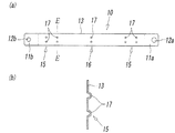
図1の(a)及び(b)には、本発明に係る位置センサ用取付バンド10を装着した流体圧シリンダ30を示している。
なお、図1に示す流体圧シリンダで、図12に示す流体圧シリンダと同一又は対応する部分には、図12と同一の符号を付してその説明を省略するが、図1の本発明に係る位置センサ用取付バンド10において、図12及び図13に示す従来の位置センサ用取付バンド10と対応する部分には便宜上同一の符号を付し、それらの相違点については、本発明に係る位置センサ用取付バンド10の構成と共に以下において具体的に説明する。
1 (a) and 1 (b) show a
In the fluid pressure cylinder shown in FIG. 1, the same or corresponding parts as those in the fluid pressure cylinder shown in FIG. 12 are denoted by the same reference numerals as those in FIG. In the position
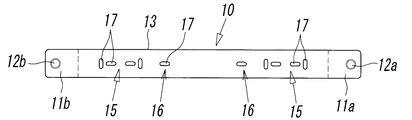
まず、本発明に係る位置センサ用取付バンド10によりシリンダチューブ31の外面に取り付ける位置センサ21は、シリンダチューブ31内のピストン32の動作位置を、該ピストン32の周囲に取り付けた永久磁石37の磁気により検出する磁気感応型のもので、上記位置センサ用取付バンド10は、該位置センサ21をシリンダチューブ31の外面に保持させるための保持部材20と、該保持部材20に両端を連結して上記シリンダチューブ31の外周に巻着され、該保持部材20をシリンダチューブ31の外周上における任意位置に固定する可撓性のある帯状金属製の薄板バンド13とにより構成している。
First, the
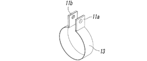
図1に示す位置センサ用取付バンド10の上記薄板バンド13は、その両端に位置センサの保持部材20を挟持するために補強された挟持部11a,11bを有している。該挟持部11a,11bが互いに相対して挟持する位置センサの保持部材20は、上記シリンダチューブ31の外周上に圧接されて位置センサ21を受けるセンサホルダ22と、該センサホルダ22上に位置して該センサホルダ22をシリンダチューブ31の外周上に押し付ける取付部材23とにより構成され、位置センサ21は上記センサホルダ22の取付溝に挿入して固定ねじ24で該センサホルダ22に固定している。そして、上記位置センサ21及び保持部材20をシリンダチューブ31の外周に固定するには、上記挟持部11aと挟持部11bとによって取付部材23の両側面を挟み、挟持部11aのねじ孔12aから取付部材23のねじ挿通孔に取付ねじ14を挿入し、該取付ねじ14を挟持部11bのねじ締付孔12bに螺挿することにより固定するようにしている。
The
一方、上記薄板バンド13は、上記帯状金属板を円弧状に湾曲させて形成し、シリンダチューブ31の外面への固定力を増大させるために、以下に図2〜図11を参照して詳述するような各種パターンの突起部15、及び必要に応じて設けられる突起部16等の複数が、該薄板バンド13の内周側に突き出た状態で設けられる。各突起部15,16は、単一又は複数の突起17の集合或いは複合により形成されるものであるが、具体的には、図2〜図11を参照して後述することとし、まず該薄板バンド13に設ける一般的な突起部15,16等の配置について説明する。
On the other hand, the
上記薄板バンド13には、まず、少なくとも、図1の(b)に示す保持部材20の中央Mの両側の対称位置に突起部15が対設される。これらの対称位置の一対の突起部15,15は、薄板バンド13においてシリンダチューブ31の保持部材20が位置する側の半周に巻着される範囲内(薄板バンド13の両端部付近)に形成されるものである。該突起部15を形成する単一又は複数の突起17自体は、具体的には、図2〜図11に示すようなものであり、これらは、シリンダチューブ31の表面に点状接触、線状接触又は面状接触するものに大別することができる。いずれの突起17も、図示しているように、薄板バンド13の長手方向の中心線に関して対称になっていることが望まれる。
First, the
特に、上記突起部15,16を構成する突起17が上記線状接触の突起である場合、薄板バンド13の長手方向に伸びる突起17はシリンダチューブ31の軸方向の外力に対して大きな固定力を発揮させることができ、また、上記薄板バンド13の幅方向に伸びる突起17は、シリンダチューブ31の円周方向の外力に対して大きな固定力を得るのに有効である。
In particular, when the
上記内周側の一部に突起部15を突出させた薄板バンド13は、それをシリンダチューブ31の外周に巻着して締め付けると、該突起部15における各突起17の先端部にその薄板バンド13の締め付け力が集中してシリンダチューブ31の外周に作用するため、大きな固定力を発生させることができ、そして、当該固定力を発生させる突起部15を上述のように保持部材20の両側の対称位置に対設すると、位置センサ21の保持部材20の固定を該保持部材20の両側で行うことになるので、その保持部材20の固定を十分に安定化させることができる。特に、図2に示すように、各突起部15に薄板バンド13の長手方向の線状成分を有する突起17aと、それに直交する幅方向の線状成分を有する突起17bとを設けると、上記保持部材20に作用するシリンダチューブ31の円周方向及び軸方向の固定力を効果的に高めることができる。なお、図2以外では、上記長手方向の突起17a及び幅方向の突起17bを、いずれも突起17として、符号による区別を省略している。
When the
例えば、シリンダチューブ31の径が大きく、従って薄板バンド13が長くなる場合などにおいて、薄板バンド13における上記保持部材20の両側に対設した突起部15だけで薄板バンド13の安定的な固定が行われない可能性がある場合には、図1の(b)や、図4,7,8,10に示すように、薄板バンド13の上記保持部材20の両側の対称位置の上記突起部15に加えて、該薄板バンド13の長手方向の中央部に、内周側に突出する中間位置の突起部16を設けることができる。しかしながら、薄板バンド13に全体的に多数の突起部を設けると、逆に、それらの多数の突起部に固定力が分散して作用することになり、この分散した固定力では必ずしも保持部材20の十分な固定を行えるとは限らない。
For example, when the diameter of the
そこで、上記保持部材20の両側の対称位置の突起部15に加えて、薄板バンド13の長手方向の中央部に中間位置の突起部16を設ける場合には、シリンダチューブ31の周面への薄板バンド13の締め付け時に、上記保持部材20の両側の対称位置の突起部15と中間位置の突起部16との間において、薄板バンド13がシリンダチューブ31の表面に十分な長さで圧接することが必要であり、これにより、薄板バンド13に全体的に多数の突起部を設ける場合に比して薄板バンド13に加える締め付け力により各突起部15,16に作用する固定力を分散させることなく、十分に大きいものにすることができる。
Therefore, in addition to the projecting
上記薄板バンド13をシリンダチューブ31の表面に十分な長さで圧接させる場合に、どの程度の圧接長さが必要であるかについて、本発明者が実験結果等に基づいて検討した結果、シリンダチューブ31の径が大きく、従って薄板バンド13が長くなる場合においては、シリンダチューブ31の周面への薄板バンド13の締め付け時に、シリンダチューブ31の周長に対して70〜80%の範囲で薄板バンド13を容易に圧接させることができるが、シリンダチューブ31の径が小さく、従って、薄板バンド13が短い場合には、薄板バンド13を保持部材20の両側の突起部15と中間位置の突起部16との間においてシリンダチューブ31の表面に圧接する十分な長さを得ることに困難性があるが、少なくとも、薄板バンド13の圧接する部分の長さがシリンダチューブ31の周長の50%以上であることが必要である。
As a result of the inventor's examination based on experimental results and the like as to how much pressure contact length is necessary when the
上記中間位置の突起部16を構成する突起17も、保持部材20の両側の突起部15における突起17と同様に、シリンダチューブ31の表面に点状接触、線状接触又は面状接触する単一又は複数のものとすることができる。
なお、上記保持部材20の両側の対称位置の突起部15に加えて、薄板バンド13の長手方向の中央部に中間位置の突起部16を設ける場合に、該突起部16は、必ずしも図1の(b)や、図4,7,8,10に示しているように、薄板バンド13の長手方向の中央部に設ける必要はなく、上述した薄板バンド13の圧接する部分の長さがシリンダチューブ31の周長の50%以上であることを前提として、例えば図9に示すように、薄板バンド13の長手方向の中央部ではない位置に必要数の突起部16を設けることもできる。
Similarly to the
In addition to the
更に、上記薄板バンド13に各突起部15,16を設けるに当たり、図3に示すように、薄板バンド13の幅方向の中央部にそれらの突起部15,16を構成する突起17が位置するようにして、即ち、それらの一部が薄板バンド13の長手方向に伸びる両側縁13aに達しない位置に設け、シリンダチューブ31に対する薄板バンド13の締め付け時に、該薄板バンド13の長手方向に伸びる両側縁13aを、各突起部15,16の配設位置の幅方向両側においてシリンダチューブ31に圧接させるように形成すると、シリンダチューブ31に対する各突起部15,16の圧接が安定化し、該突起部により安定的な固定力を発生させることができる。この場合に、上記薄板バンド13の幅方向の中央部に位置する各突起部15,16が、該薄板バンド13の幅の1/2以下の範囲内にあり、各突起部15,16の配設位置の両側に少なくとも該薄板バンド13の幅の1/4以上の突起部を設けていない領域があることが望まれる。
Further, when the
次に、図4〜図11を参照して、上記突起部15,16を構成する各突起17の具体的形態について説明する。
図4の(a)〜(d)の例は、薄板バンド13に設けた各突起部15,16が、それぞれ線状接触する単一の突起17により形成されたもので、(a)では、上記薄板バンド13の幅方向の線状成分を有する各単一の突起17を備えた場合、(b)〜(d)では、上記薄板バンド13の長手方向の線状成分を有する突起とそれに直交する幅方向の線状成分を有する突起との複合により、十状に形成された突起17、X状に形成された突起17、並びに倒T字状及び十状に形成された突起17の混用の場合を例示している。特に、上記(b)〜(d)の例では、薄板バンド13の長手方向の線状成分を有する突起とそれに直交する幅方向の線状成分を有する突起との複合により突起17が形成されているので、それらの突起17により、保持部材20におけるシリンダチューブ31の円周方向及び軸方向の固定力を効果的に高めることができる。
Next, with reference to FIGS. 4-11, the specific form of each
In the example of FIGS. 4A to 4D, each of the
また、図6〜図11は、突起部15が複数の突起17により形成された例を示すものであり、図6及び図7では、突起部15における複数の突起17が、薄板バンド13の長手方向の線状成分を有する突起と、それに直交する幅方向の線状成分を有する突起との複合により形成され、図8及び図9の例では、突起部15における複数の突起17が、薄板バンド13の長手方向の線状成分を有する突起とそれに直交する幅方向の線状成分を有する突起の複数の集合により形成されている。これらの複数の突起17を近接配置する場合には、隣接する突起17の機能がそれぞれ十分に発揮されるような配列であることが望ましく、特に、薄板バンド13の幅方向の線状成分を有する突起17を相互に隣接させると、それらの突起は分散配置されている場合よりも、保持部材20におけるシリンダチューブ31の円周方向の固定力を高めることができるとは限らないので、そのような配列は避けるべきである。
FIGS. 6 to 11 show an example in which the
しかも、上記図4及び図6〜図9に示す例では、突起部15を形成する複数の突起17が、薄板バンド13の長手方向の線状成分を有する突起と、それに直交する幅方向の線状成分を有する突起との複合或いは集合により形成されているので、それらを、文字その他の記号状に形成することもでき、例えば、ローマ字の中から選ばれる任意文字形状に形成することができる。
In addition, in the examples shown in FIGS. 4 and 6 to 9, the plurality of
更に、図10では、各突起部15,16に、シリンダチューブ31に対して面状接触する突起17を設けた場合を示しているが、かかる突起17は、シリンダチューブ31との接触部が面状であって、その接触面における単位面積当たり圧接力が小さくなるので、必ずしもシリンダチューブ31に対する薄板バンド13の固定力を高めるために有効なものではないが、例えば、シリンダチューブ31の強度に問題があって単位面積当たりの突起の押し付け力をある程度制限したい場合などに有効である。
Further, FIG. 10 shows a case where each of the
図11には、各突起部15,16が、シリンダチューブ31に点状接触する突起17を薄板バンド13の幅方向の2位置に並び、しかも、突起部15はそれを薄板バンド13の長手方向にも並べて配設することにより形成された例を示している。このような構成は、各突起17が点状という簡易なものでありながら、例えば、図3に示しているように、シリンダチューブ31に対する薄板バンド13の締め付け時に、各突起17の配設位置の幅方向両側において、薄板バンド13の長手方向に伸びる両側縁13aをシリンダチューブ31に圧接させることにより、該薄板バンド13のシリンダチューブ31への固定を安定させることができる。
In FIG. 11, the
上述した薄板バンド13の各例においては、保持部材20の両側の対称位置に設けた突起部15が、該保持部材20の中央の両側において対称形状をなす単一又は複数の突起により形成されているが、このような形状は、保持部材20の両側における固定力を均等化し、その固定を安定化させるために有効なものである。
また、保持部材20の両側の対称位置に設けた突起部15を、該保持部材20の中央の両側において対称形状にしておくのは、該薄板バンド13の製造において薄板バンド13の両端を共通の型によりプレス加工するなどにより、製造上のコスト低減を図るためにも有効なものである。
In each example of the
Further, the
10 位置センサ用取付バンド
11a,11b 挟持部
13 薄板バンド
15,16 突起部
20 保持部材
21 位置センサ
31 シリンダチューブ
DESCRIPTION OF
Claims (9)
上記薄板バンドは、上記保持部材の両側の対称位置と、該薄板バンドの長手方向の中央位置とのうち、少なくとも上記対称位置に、該薄板バンドの内周側に突出する単一又は複数の突起を備えた突起部を有し、該突起部が形成された位置は、上記薄板バンドの、上記保持部材が位置するシリンダチューブ半周側に巻着される部分であり、
上記突起部は、上記薄板バンドの幅方向の中央部に、該薄板バンドの幅の1/2以下の範囲内に位置するように配設され、該突起部の配設位置の両側には、上記薄板バンドの幅の少なくとも1/4以上の突起部が設けられていない領域があり、シリンダチューブの周面に対する上記薄板バンドの締め付け時に上記領域が上記シリンダチューブに接触するように形成されている、
ことを特徴とする位置センサ用取付バンド。 For a position sensor comprising a holding member for holding a position sensor for detecting an operating position of a piston in the cylinder tube, and a thin band that is connected to the holding member at both ends and wound around the outer circumference of the cylinder tube In the mounting band,
The thin plate band is a single or a plurality of protrusions protruding toward the inner peripheral side of the thin plate band at least in the symmetrical position among the symmetrical positions on both sides of the holding member and the longitudinal center position of the thin plate band. The position where the protrusion is formed is a portion of the thin plate band that is wound around the cylinder tube half circumference side where the holding member is located,
The protrusion is disposed at a central portion in the width direction of the thin plate band so as to be located within a range of 1/2 or less of the width of the thin plate band. There is a region in which no protrusion of at least 1/4 of the width of the thin plate band is provided, and the region is formed so as to contact the cylinder tube when the thin plate band is tightened with respect to the peripheral surface of the cylinder tube. ,
A mounting band for a position sensor.
ことを特徴とする請求項1に記載の位置センサ用取付バンド。 The thin plate band has the protrusions at symmetrical positions on both sides of the holding member and a central position in the longitudinal direction of the thin plate band, and between the protrusion portions at the symmetrical position and the protrusion portions at the intermediate position, The thin plate band has a portion that presses the surface of the cylinder tube when tightened to the peripheral surface of the cylinder tube, and the length of the press contact portion of the thin plate band is 50% or more of the peripheral length of the cylinder tube.
The position sensor mounting band according to claim 1.
ことを特徴とする請求項1〜3のいずれかに記載の位置センサ用取付バンド。 Each of the protrusions is formed by a protrusion having a linear component in the longitudinal direction of the thin plate band and a protrusion having a linear component in the width direction perpendicular to the protrusion.
The mounting band for a position sensor according to any one of claims 1 to 3 .
ことを特徴とする請求項1〜3のいずれかに記載の位置センサ用取付バンド。 Each of the protrusions is formed by one or a plurality of protrusions that combine the longitudinal direction of the thin plate band and the linear component in the width direction perpendicular thereto.
The mounting band for a position sensor according to any one of claims 1 to 3 .
ことを特徴とする請求項1〜3のいずれかに記載の位置センサ用取付バンド。 Each of the protrusions is formed by one or a plurality of protrusions that are combined by intersecting X-shaped linear components inclined with respect to the longitudinal direction of the thin plate band.
The mounting band for a position sensor according to any one of claims 1 to 3 .
ことを特徴とする請求項4〜6のいずれかに記載の位置センサ用取付バンド。 The protrusion is formed in a letter or other symbol shape by a set or combination of protrusions,
The position sensor mounting band according to any one of claims 4 to 6 .
ことを特徴とする請求項4〜7のいずれかに記載の位置センサ用取付バンド。 Protrusions provided at symmetrical positions on both sides of the holding member are formed by a single or a plurality of protrusions having a symmetrical shape on both sides of the center of the holding member.
The position sensor mounting band according to claim 4 , wherein the position sensor mounting band is provided.
ことを特徴とする請求項1〜3のいずれかに記載の位置センサ用取付バンド。 Each of the protrusions is formed by disposing protrusions that make point contact with the cylinder tube at two positions in the width direction of the thin plate band.
The mounting band for a position sensor according to any one of claims 1 to 3 .
Priority Applications (10)
| Application Number | Priority Date | Filing Date | Title |
|---|---|---|---|
| JP2011198407A JP5914929B2 (en) | 2011-09-12 | 2011-09-12 | Mounting band for position sensor |
| US14/344,451 US9528816B2 (en) | 2011-09-12 | 2012-08-30 | Position sensor attachment band |
| DE112012003794.4T DE112012003794B4 (en) | 2011-09-12 | 2012-08-30 | Position sensor attachment strap |
| BR112014005692-7A BR112014005692B1 (en) | 2011-09-12 | 2012-08-30 | position sensor attachment band |
| RU2014114498/06A RU2574696C2 (en) | 2011-09-12 | 2012-08-30 | Securing tape of position sensor |
| IN2644CHN2014 IN2014CN02644A (en) | 2011-09-12 | 2012-08-30 | |
| KR1020147008131A KR101696294B1 (en) | 2011-09-12 | 2012-08-30 | Position sensor attachment band |
| CN201280044215.2A CN103782042B (en) | 2011-09-12 | 2012-08-30 | Position transducer mounting strap hoop |
| PCT/JP2012/072008 WO2013038917A1 (en) | 2011-09-12 | 2012-08-30 | Position sensor attachment band |
| TW101131804A TWI503486B (en) | 2011-09-12 | 2012-08-31 | Position sensor mounting strap |
Applications Claiming Priority (1)
| Application Number | Priority Date | Filing Date | Title |
|---|---|---|---|
| JP2011198407A JP5914929B2 (en) | 2011-09-12 | 2011-09-12 | Mounting band for position sensor |
Publications (2)
| Publication Number | Publication Date |
|---|---|
| JP2013060980A JP2013060980A (en) | 2013-04-04 |
| JP5914929B2 true JP5914929B2 (en) | 2016-05-11 |
Family
ID=47883150
Family Applications (1)
| Application Number | Title | Priority Date | Filing Date |
|---|---|---|---|
| JP2011198407A Active JP5914929B2 (en) | 2011-09-12 | 2011-09-12 | Mounting band for position sensor |
Country Status (9)
| Country | Link |
|---|---|
| US (1) | US9528816B2 (en) |
| JP (1) | JP5914929B2 (en) |
| KR (1) | KR101696294B1 (en) |
| CN (1) | CN103782042B (en) |
| BR (1) | BR112014005692B1 (en) |
| DE (1) | DE112012003794B4 (en) |
| IN (1) | IN2014CN02644A (en) |
| TW (1) | TWI503486B (en) |
| WO (1) | WO2013038917A1 (en) |
Families Citing this family (4)
| Publication number | Priority date | Publication date | Assignee | Title |
|---|---|---|---|---|
| JP6098896B2 (en) * | 2014-06-05 | 2017-03-22 | Smc株式会社 | Sensor mounting device for fluid pressure cylinder |
| US10138914B2 (en) * | 2015-04-16 | 2018-11-27 | Smc Corporation | Sensor attachment tool |
| CN106523462B (en) * | 2016-12-30 | 2018-02-13 | 北京强度环境研究所 | A kind of high precision displacement control cylinder device and its control method |
| ES1257574Y (en) * | 2020-08-26 | 2021-02-26 | Cebi Electromechanical Components Spain S A | FIXING SYSTEM OF A POSITION SENSOR |
Family Cites Families (23)
| Publication number | Priority date | Publication date | Assignee | Title |
|---|---|---|---|---|
| US4592576A (en) * | 1983-12-12 | 1986-06-03 | Murray Corporation | Hose clamp with inclined barbs |
| JPS60188311A (en) | 1984-03-07 | 1985-09-25 | Soda Koryo Kk | Germicidal coating agent |
| JPS60188311U (en) * | 1984-05-23 | 1985-12-13 | 株式会社 小金井製作所 | Piston stroke sensor mounting band |
| JPH07103226B2 (en) | 1987-02-04 | 1995-11-08 | 凸版印刷株式会社 | Method for manufacturing conductive film |
| JPS63191822U (en) * | 1987-05-28 | 1988-12-09 | ||
| US4875647A (en) | 1987-04-24 | 1989-10-24 | Daiwa Kasei Kogyo Kabushiki Kausha | Cable tie |
| JPS6447518A (en) | 1987-08-19 | 1989-02-22 | Art Plus Kk | Preparation of cellulose acetate propionate plastic having built-up pattern |
| JPS6471204A (en) * | 1987-09-11 | 1989-03-16 | Hitachi Ltd | Analog input circuit |
| FR2620530B1 (en) * | 1987-09-16 | 1991-04-12 | Celduc | ELECTRICAL SENSOR DEVICE |
| JPS6447518U (en) * | 1987-09-17 | 1989-03-23 | ||
| SE463684B (en) * | 1989-12-22 | 1991-01-07 | Mecman Ab | MAINTENANCE DEVICE FOR POSITION SENSOR |
| JP2548910Y2 (en) * | 1991-03-26 | 1997-09-24 | 株式会社コガネイ | Hydraulic cylinder position sensor mounting structure |
| JPH0517208U (en) * | 1991-08-19 | 1993-03-05 | 株式会社コガネイ | Position sensor mounting structure for fluid pressure actuator |
| JPH0861316A (en) * | 1994-08-22 | 1996-03-08 | Piolax Inc | Harness binding clip |
| JP3875622B2 (en) * | 2002-08-06 | 2007-01-31 | シーケーディ株式会社 | Mounting structure for accessory members for actuators |
| JP3951188B2 (en) * | 2004-03-05 | 2007-08-01 | Smc株式会社 | Cylinder position detection switch fitting |
| TWM304613U (en) * | 2006-06-06 | 2007-01-11 | Jin-Ting You | Improved structure of high pressure pipe clamp |
| CN201050521Y (en) * | 2007-05-15 | 2008-04-23 | 经登企业股份有限公司 | Inducer fixing device |
| JP4529093B2 (en) * | 2007-12-19 | 2010-08-25 | Smc株式会社 | Piston position detection device for fluid pressure cylinder |
| JP2010065839A (en) * | 2008-09-12 | 2010-03-25 | Smc Corp | Sensor mounting holder for fluid pressure cylinder |
| US20110076096A1 (en) * | 2009-09-25 | 2011-03-31 | Saint-Gobain Performance Plastics Rencol Limited | System, method and apparatus for tolerance ring control of slip interface sliding forces |
| CN201593653U (en) * | 2009-12-17 | 2010-09-29 | 江门市蓬江区欧罗富五金橡胶制品有限公司 | Quick-installation pipe clamp |
| JP5382591B2 (en) * | 2010-12-21 | 2014-01-08 | Smc株式会社 | Fluid pressure cylinder position detection device |
-
2011
- 2011-09-12 JP JP2011198407A patent/JP5914929B2/en active Active
-
2012
- 2012-08-30 US US14/344,451 patent/US9528816B2/en active Active
- 2012-08-30 IN IN2644CHN2014 patent/IN2014CN02644A/en unknown
- 2012-08-30 CN CN201280044215.2A patent/CN103782042B/en not_active Expired - Fee Related
- 2012-08-30 BR BR112014005692-7A patent/BR112014005692B1/en not_active IP Right Cessation
- 2012-08-30 DE DE112012003794.4T patent/DE112012003794B4/en active Active
- 2012-08-30 WO PCT/JP2012/072008 patent/WO2013038917A1/en active Application Filing
- 2012-08-30 KR KR1020147008131A patent/KR101696294B1/en active IP Right Grant
- 2012-08-31 TW TW101131804A patent/TWI503486B/en not_active IP Right Cessation
Also Published As
| Publication number | Publication date |
|---|---|
| TW201315902A (en) | 2013-04-16 |
| CN103782042B (en) | 2016-06-01 |
| CN103782042A (en) | 2014-05-07 |
| BR112014005692A2 (en) | 2017-03-28 |
| IN2014CN02644A (en) | 2015-08-07 |
| WO2013038917A1 (en) | 2013-03-21 |
| RU2014114498A (en) | 2015-10-20 |
| KR20140063746A (en) | 2014-05-27 |
| KR101696294B1 (en) | 2017-01-13 |
| DE112012003794B4 (en) | 2022-03-24 |
| BR112014005692B1 (en) | 2021-02-23 |
| DE112012003794T5 (en) | 2014-06-12 |
| US9528816B2 (en) | 2016-12-27 |
| JP2013060980A (en) | 2013-04-04 |
| US20140266167A1 (en) | 2014-09-18 |
| TWI503486B (en) | 2015-10-11 |
Similar Documents
| Publication | Publication Date | Title |
|---|---|---|
| JP5914929B2 (en) | Mounting band for position sensor | |
| EP2708442B1 (en) | Steering apparatus | |
| JP6917298B2 (en) | clip | |
| JP2006308092A (en) | Pad retaining clip | |
| JP6282129B2 (en) | Fishing line guide frame, fishing line guide and fishing rod | |
| US20130133999A1 (en) | Protection clip for torque receiving part and method of forming attaching recess thereof | |
| US10113569B2 (en) | Sensor mounting device for hydraulic cylinder | |
| US8537556B2 (en) | Holding apparatus | |
| KR20180097675A (en) | Brake linings for railway vehicles and disc brakes having the same | |
| TWI694021B (en) | Brake pads for railway vehicles and disc brakes with the same | |
| RU2574696C2 (en) | Securing tape of position sensor | |
| CN110687972A (en) | Hard disk assembling device | |
| CN213876224U (en) | Limiting jig | |
| JP2002081928A (en) | Unit-type linear scale | |
| US20100314203A1 (en) | Method for the assembly of a wear indicator on a brake | |
| US11835070B2 (en) | Sensor attachment tool and fluid pressure cylinder | |
| JP6252444B2 (en) | Load detection device | |
| KR20130131746A (en) | Steering column of vehicle | |
| JP4486025B2 (en) | Load sensor | |
| JP2007263953A (en) | Load sensor | |
| JP2005181133A (en) | Torque detection device | |
| CN103663046A (en) | Integral flange system used for fastening elevator guiding device onto fixing structure | |
| JP2019184420A (en) | Mounting jig and temperature detector | |
| JP2023142201A (en) | Substrate fixing structure | |
| JP2022069262A (en) | cable clamp |
Legal Events
| Date | Code | Title | Description |
|---|---|---|---|
| A621 | Written request for application examination |
Free format text: JAPANESE INTERMEDIATE CODE: A621 Effective date: 20130604 |
|
| A131 | Notification of reasons for refusal |
Free format text: JAPANESE INTERMEDIATE CODE: A131 Effective date: 20140422 |
|
| A521 | Request for written amendment filed |
Free format text: JAPANESE INTERMEDIATE CODE: A523 Effective date: 20140526 |
|
| TRDD | Decision of grant or rejection written | ||
| A01 | Written decision to grant a patent or to grant a registration (utility model) |
Free format text: JAPANESE INTERMEDIATE CODE: A01 Effective date: 20141118 |
|
| A61 | First payment of annual fees (during grant procedure) |
Free format text: JAPANESE INTERMEDIATE CODE: A61 Effective date: 20141215 |
|
| A61 | First payment of annual fees (during grant procedure) |
Free format text: JAPANESE INTERMEDIATE CODE: A61 Effective date: 20160105 |
|
| A61 | First payment of annual fees (during grant procedure) |
Free format text: JAPANESE INTERMEDIATE CODE: A61 Effective date: 20160316 |
|
| R150 | Certificate of patent or registration of utility model |
Ref document number: 5914929 Country of ref document: JP Free format text: JAPANESE INTERMEDIATE CODE: R150 |
|
| R250 | Receipt of annual fees |
Free format text: JAPANESE INTERMEDIATE CODE: R250 |
|
| R250 | Receipt of annual fees |
Free format text: JAPANESE INTERMEDIATE CODE: R250 |
|
| R250 | Receipt of annual fees |
Free format text: JAPANESE INTERMEDIATE CODE: R250 |
|
| R250 | Receipt of annual fees |
Free format text: JAPANESE INTERMEDIATE CODE: R250 |
|
| R250 | Receipt of annual fees |
Free format text: JAPANESE INTERMEDIATE CODE: R250 |
|
| R250 | Receipt of annual fees |
Free format text: JAPANESE INTERMEDIATE CODE: R250 |