JP5914464B2 - Method for improving bioactive properties of surfaces and objects having improved surfaces thereby - Google Patents
Method for improving bioactive properties of surfaces and objects having improved surfaces thereby Download PDFInfo
- Publication number
- JP5914464B2 JP5914464B2 JP2013509264A JP2013509264A JP5914464B2 JP 5914464 B2 JP5914464 B2 JP 5914464B2 JP 2013509264 A JP2013509264 A JP 2013509264A JP 2013509264 A JP2013509264 A JP 2013509264A JP 5914464 B2 JP5914464 B2 JP 5914464B2
- Authority
- JP
- Japan
- Prior art keywords
- gcib
- gas cluster
- ion beam
- cluster ion
- neutral particle
- Prior art date
- Legal status (The legal status is an assumption and is not a legal conclusion. Google has not performed a legal analysis and makes no representation as to the accuracy of the status listed.)
- Expired - Fee Related
Links
- 238000000034 method Methods 0.000 title claims description 60
- 230000001976 improved effect Effects 0.000 title description 44
- 230000000975 bioactive effect Effects 0.000 title description 8
- 230000007935 neutral effect Effects 0.000 claims description 129
- 239000002245 particle Substances 0.000 claims description 97
- 239000000463 material Substances 0.000 claims description 60
- 239000000178 monomer Substances 0.000 claims description 59
- 239000004696 Poly ether ether ketone Substances 0.000 claims description 58
- 229920002530 polyetherether ketone Polymers 0.000 claims description 58
- 238000010884 ion-beam technique Methods 0.000 claims description 49
- 239000000835 fiber Substances 0.000 claims description 40
- RTAQQCXQSZGOHL-UHFFFAOYSA-N Titanium Chemical compound [Ti] RTAQQCXQSZGOHL-UHFFFAOYSA-N 0.000 claims description 38
- 239000010936 titanium Substances 0.000 claims description 38
- 229910052719 titanium Inorganic materials 0.000 claims description 37
- 238000002513 implantation Methods 0.000 claims description 32
- 239000004793 Polystyrene Substances 0.000 claims description 31
- 229920002223 polystyrene Polymers 0.000 claims description 31
- 239000005020 polyethylene terephthalate Substances 0.000 claims description 28
- 239000011521 glass Substances 0.000 claims description 27
- 229920000139 polyethylene terephthalate Polymers 0.000 claims description 27
- 229920000642 polymer Polymers 0.000 claims description 27
- 210000000988 bone and bone Anatomy 0.000 claims description 21
- 239000004810 polytetrafluoroethylene Substances 0.000 claims description 17
- 229920001343 polytetrafluoroethylene Polymers 0.000 claims description 17
- VYPSYNLAJGMNEJ-UHFFFAOYSA-N silicon dioxide Inorganic materials O=[Si]=O VYPSYNLAJGMNEJ-UHFFFAOYSA-N 0.000 claims description 16
- GWEVSGVZZGPLCZ-UHFFFAOYSA-N Titan oxide Chemical compound O=[Ti]=O GWEVSGVZZGPLCZ-UHFFFAOYSA-N 0.000 claims description 15
- 229920001577 copolymer Polymers 0.000 claims description 14
- 229940079593 drug Drugs 0.000 claims description 14
- 239000003814 drug Substances 0.000 claims description 14
- -1 polyethylene Polymers 0.000 claims description 14
- 241000124008 Mammalia Species 0.000 claims description 13
- WAIPAZQMEIHHTJ-UHFFFAOYSA-N [Cr].[Co] Chemical class [Cr].[Co] WAIPAZQMEIHHTJ-UHFFFAOYSA-N 0.000 claims description 13
- 239000010980 sapphire Substances 0.000 claims description 13
- 229910052594 sapphire Inorganic materials 0.000 claims description 13
- 239000004033 plastic Substances 0.000 claims description 12
- 229920003023 plastic Polymers 0.000 claims description 12
- 239000007943 implant Substances 0.000 claims description 11
- 239000000919 ceramic Substances 0.000 claims description 9
- 230000010261 cell growth Effects 0.000 claims description 8
- 108010035532 Collagen Proteins 0.000 claims description 7
- 102000008186 Collagen Human genes 0.000 claims description 7
- 229920001436 collagen Polymers 0.000 claims description 7
- 230000001678 irradiating effect Effects 0.000 claims description 7
- 229910052751 metal Inorganic materials 0.000 claims description 7
- 239000002184 metal Substances 0.000 claims description 7
- 230000003472 neutralizing effect Effects 0.000 claims description 7
- 239000010453 quartz Substances 0.000 claims description 7
- 239000011347 resin Substances 0.000 claims description 6
- 229920005989 resin Polymers 0.000 claims description 6
- 239000012620 biological material Substances 0.000 claims description 5
- 239000007787 solid Substances 0.000 claims description 5
- 239000004698 Polyethylene Substances 0.000 claims description 4
- 229910001069 Ti alloy Inorganic materials 0.000 claims description 4
- 239000012777 electrically insulating material Substances 0.000 claims description 4
- 229920000573 polyethylene Polymers 0.000 claims description 4
- 229910001362 Ta alloys Inorganic materials 0.000 claims description 3
- 229910001092 metal group alloy Inorganic materials 0.000 claims description 3
- 229910052715 tantalum Inorganic materials 0.000 claims description 3
- GUVRBAGPIYLISA-UHFFFAOYSA-N tantalum atom Chemical compound [Ta] GUVRBAGPIYLISA-UHFFFAOYSA-N 0.000 claims description 3
- 239000002657 fibrous material Substances 0.000 claims description 2
- 230000001939 inductive effect Effects 0.000 claims description 2
- 230000006837 decompression Effects 0.000 claims 2
- 229920001296 polysiloxane Polymers 0.000 claims 1
- 239000005060 rubber Substances 0.000 claims 1
- 239000000602 vitallium Substances 0.000 claims 1
- 239000007789 gas Substances 0.000 description 177
- 210000004027 cell Anatomy 0.000 description 142
- 150000002500 ions Chemical class 0.000 description 111
- 238000012545 processing Methods 0.000 description 68
- XKRFYHLGVUSROY-UHFFFAOYSA-N Argon Chemical compound [Ar] XKRFYHLGVUSROY-UHFFFAOYSA-N 0.000 description 48
- 238000005259 measurement Methods 0.000 description 38
- 230000001133 acceleration Effects 0.000 description 35
- 230000012010 growth Effects 0.000 description 28
- 239000000758 substrate Substances 0.000 description 28
- 229910052786 argon Inorganic materials 0.000 description 24
- 108091003079 Bovine Serum Albumin Proteins 0.000 description 22
- 239000012091 fetal bovine serum Substances 0.000 description 22
- 239000006144 Dulbecco’s modified Eagle's medium Substances 0.000 description 21
- UCSJYZPVAKXKNQ-HZYVHMACSA-N streptomycin Chemical compound CN[C@H]1[C@H](O)[C@@H](O)[C@H](CO)O[C@H]1O[C@@H]1[C@](C=O)(O)[C@H](C)O[C@H]1O[C@@H]1[C@@H](NC(N)=N)[C@H](O)[C@@H](NC(N)=N)[C@H](O)[C@H]1O UCSJYZPVAKXKNQ-HZYVHMACSA-N 0.000 description 20
- 230000006872 improvement Effects 0.000 description 19
- 239000000203 mixture Substances 0.000 description 19
- 238000000879 optical micrograph Methods 0.000 description 19
- 210000000963 osteoblast Anatomy 0.000 description 19
- 238000010899 nucleation Methods 0.000 description 18
- 230000035755 proliferation Effects 0.000 description 18
- 238000004113 cell culture Methods 0.000 description 17
- 235000015097 nutrients Nutrition 0.000 description 17
- 238000012360 testing method Methods 0.000 description 15
- 210000001519 tissue Anatomy 0.000 description 15
- 238000004980 dosimetry Methods 0.000 description 14
- 238000011534 incubation Methods 0.000 description 14
- 239000002609 medium Substances 0.000 description 13
- 230000003287 optical effect Effects 0.000 description 13
- OKKJLVBELUTLKV-UHFFFAOYSA-N Methanol Chemical compound OC OKKJLVBELUTLKV-UHFFFAOYSA-N 0.000 description 12
- 230000008901 benefit Effects 0.000 description 12
- 238000001000 micrograph Methods 0.000 description 12
- 230000008569 process Effects 0.000 description 12
- 230000001464 adherent effect Effects 0.000 description 11
- 238000000576 coating method Methods 0.000 description 11
- 229930182555 Penicillin Natural products 0.000 description 10
- JGSARLDLIJGVTE-MBNYWOFBSA-N Penicillin G Chemical compound N([C@H]1[C@H]2SC([C@@H](N2C1=O)C(O)=O)(C)C)C(=O)CC1=CC=CC=C1 JGSARLDLIJGVTE-MBNYWOFBSA-N 0.000 description 10
- 230000004907 flux Effects 0.000 description 10
- 230000001965 increasing effect Effects 0.000 description 10
- 238000003754 machining Methods 0.000 description 10
- 229940049954 penicillin Drugs 0.000 description 10
- 229960005322 streptomycin Drugs 0.000 description 10
- KFZMGEQAYNKOFK-UHFFFAOYSA-N Isopropanol Chemical compound CC(C)O KFZMGEQAYNKOFK-UHFFFAOYSA-N 0.000 description 9
- 241000700159 Rattus Species 0.000 description 9
- 239000012634 fragment Substances 0.000 description 9
- 229910002091 carbon monoxide Inorganic materials 0.000 description 8
- 230000000694 effects Effects 0.000 description 8
- 238000005516 engineering process Methods 0.000 description 8
- 238000001704 evaporation Methods 0.000 description 8
- 230000008020 evaporation Effects 0.000 description 8
- 230000010354 integration Effects 0.000 description 8
- 230000007246 mechanism Effects 0.000 description 8
- 238000001878 scanning electron micrograph Methods 0.000 description 8
- 238000003556 assay Methods 0.000 description 7
- 238000010494 dissociation reaction Methods 0.000 description 7
- 230000005593 dissociations Effects 0.000 description 7
- 210000002889 endothelial cell Anatomy 0.000 description 7
- 210000002950 fibroblast Anatomy 0.000 description 7
- 238000000338 in vitro Methods 0.000 description 7
- 239000000126 substance Substances 0.000 description 7
- IJGRMHOSHXDMSA-UHFFFAOYSA-N Atomic nitrogen Chemical compound N#N IJGRMHOSHXDMSA-UHFFFAOYSA-N 0.000 description 6
- 230000015572 biosynthetic process Effects 0.000 description 6
- 230000004663 cell proliferation Effects 0.000 description 6
- 239000011248 coating agent Substances 0.000 description 6
- 230000006378 damage Effects 0.000 description 6
- 239000010408 film Substances 0.000 description 6
- 239000012737 fresh medium Substances 0.000 description 6
- 230000002792 vascular Effects 0.000 description 6
- 238000001516 cell proliferation assay Methods 0.000 description 5
- 238000004140 cleaning Methods 0.000 description 5
- 230000001605 fetal effect Effects 0.000 description 5
- 230000006870 function Effects 0.000 description 5
- 239000000047 product Substances 0.000 description 5
- 241001465754 Metazoa Species 0.000 description 4
- 239000000788 chromium alloy Substances 0.000 description 4
- 238000011109 contamination Methods 0.000 description 4
- 230000007547 defect Effects 0.000 description 4
- 238000009826 distribution Methods 0.000 description 4
- 230000005684 electric field Effects 0.000 description 4
- 230000007613 environmental effect Effects 0.000 description 4
- 238000005530 etching Methods 0.000 description 4
- 238000000605 extraction Methods 0.000 description 4
- 238000013467 fragmentation Methods 0.000 description 4
- 238000006062 fragmentation reaction Methods 0.000 description 4
- 238000009499 grossing Methods 0.000 description 4
- 239000011810 insulating material Substances 0.000 description 4
- 210000003041 ligament Anatomy 0.000 description 4
- 150000002739 metals Chemical class 0.000 description 4
- 230000004048 modification Effects 0.000 description 4
- 238000012986 modification Methods 0.000 description 4
- 230000036961 partial effect Effects 0.000 description 4
- 229920001223 polyethylene glycol Polymers 0.000 description 4
- IYMAXBFPHPZYIK-BQBZGAKWSA-N Arg-Gly-Asp Chemical class NC(N)=NCCC[C@H](N)C(=O)NCC(=O)N[C@@H](CC(O)=O)C(O)=O IYMAXBFPHPZYIK-BQBZGAKWSA-N 0.000 description 3
- 239000002253 acid Substances 0.000 description 3
- 230000009286 beneficial effect Effects 0.000 description 3
- 230000005540 biological transmission Effects 0.000 description 3
- 230000008468 bone growth Effects 0.000 description 3
- 230000021164 cell adhesion Effects 0.000 description 3
- 239000003153 chemical reaction reagent Substances 0.000 description 3
- 230000001419 dependent effect Effects 0.000 description 3
- 238000010586 diagram Methods 0.000 description 3
- BRZYSWJRSDMWLG-CAXSIQPQSA-N geneticin Natural products O1C[C@@](O)(C)[C@H](NC)[C@@H](O)[C@H]1O[C@@H]1[C@@H](O)[C@H](O[C@@H]2[C@@H]([C@@H](O)[C@H](O)[C@@H](C(C)O)O2)N)[C@@H](N)C[C@H]1N BRZYSWJRSDMWLG-CAXSIQPQSA-N 0.000 description 3
- 238000010438 heat treatment Methods 0.000 description 3
- 238000003384 imaging method Methods 0.000 description 3
- 239000010410 layer Substances 0.000 description 3
- 230000033001 locomotion Effects 0.000 description 3
- 229910052757 nitrogen Inorganic materials 0.000 description 3
- 230000035515 penetration Effects 0.000 description 3
- 210000002381 plasma Anatomy 0.000 description 3
- 230000001737 promoting effect Effects 0.000 description 3
- 235000018102 proteins Nutrition 0.000 description 3
- 108090000623 proteins and genes Proteins 0.000 description 3
- 102000004169 proteins and genes Human genes 0.000 description 3
- 230000002829 reductive effect Effects 0.000 description 3
- 238000005488 sandblasting Methods 0.000 description 3
- 238000000926 separation method Methods 0.000 description 3
- 239000013589 supplement Substances 0.000 description 3
- 238000009736 wetting Methods 0.000 description 3
- 108010088751 Albumins Proteins 0.000 description 2
- 102000009027 Albumins Human genes 0.000 description 2
- CURLTUGMZLYLDI-UHFFFAOYSA-N Carbon dioxide Chemical compound O=C=O CURLTUGMZLYLDI-UHFFFAOYSA-N 0.000 description 2
- 229910000684 Cobalt-chrome Inorganic materials 0.000 description 2
- WZUVPPKBWHMQCE-UHFFFAOYSA-N Haematoxylin Chemical compound C12=CC(O)=C(O)C=C2CC2(O)C1C1=CC=C(O)C(O)=C1OC2 WZUVPPKBWHMQCE-UHFFFAOYSA-N 0.000 description 2
- 229910001182 Mo alloy Inorganic materials 0.000 description 2
- CBENFWSGALASAD-UHFFFAOYSA-N Ozone Chemical compound [O-][O+]=O CBENFWSGALASAD-UHFFFAOYSA-N 0.000 description 2
- 229910010413 TiO 2 Inorganic materials 0.000 description 2
- 208000027418 Wounds and injury Diseases 0.000 description 2
- MCMNRKCIXSYSNV-UHFFFAOYSA-N Zirconium dioxide Chemical compound O=[Zr]=O MCMNRKCIXSYSNV-UHFFFAOYSA-N 0.000 description 2
- MTHLBYMFGWSRME-UHFFFAOYSA-N [Cr].[Co].[Mo] Chemical compound [Cr].[Co].[Mo] MTHLBYMFGWSRME-UHFFFAOYSA-N 0.000 description 2
- 238000002835 absorbance Methods 0.000 description 2
- 229910045601 alloy Inorganic materials 0.000 description 2
- 239000000956 alloy Substances 0.000 description 2
- 108010072041 arginyl-glycyl-aspartic acid Proteins 0.000 description 2
- QVGXLLKOCUKJST-UHFFFAOYSA-N atomic oxygen Chemical compound [O] QVGXLLKOCUKJST-UHFFFAOYSA-N 0.000 description 2
- 210000001124 body fluid Anatomy 0.000 description 2
- 239000010839 body fluid Substances 0.000 description 2
- 210000005013 brain tissue Anatomy 0.000 description 2
- 238000011088 calibration curve Methods 0.000 description 2
- 238000003763 carbonization Methods 0.000 description 2
- 239000006285 cell suspension Substances 0.000 description 2
- 239000010952 cobalt-chrome Substances 0.000 description 2
- 238000004891 communication Methods 0.000 description 2
- 239000004020 conductor Substances 0.000 description 2
- 238000001816 cooling Methods 0.000 description 2
- 238000004132 cross linking Methods 0.000 description 2
- 239000004053 dental implant Substances 0.000 description 2
- 238000013461 design Methods 0.000 description 2
- 239000003989 dielectric material Substances 0.000 description 2
- 239000012154 double-distilled water Substances 0.000 description 2
- 238000000635 electron micrograph Methods 0.000 description 2
- 238000002474 experimental method Methods 0.000 description 2
- 230000002349 favourable effect Effects 0.000 description 2
- 230000035876 healing Effects 0.000 description 2
- 210000001624 hip Anatomy 0.000 description 2
- 238000005286 illumination Methods 0.000 description 2
- 238000007373 indentation Methods 0.000 description 2
- 238000004519 manufacturing process Methods 0.000 description 2
- 238000000386 microscopy Methods 0.000 description 2
- 210000005036 nerve Anatomy 0.000 description 2
- 238000006386 neutralization reaction Methods 0.000 description 2
- 239000001301 oxygen Substances 0.000 description 2
- 229910052760 oxygen Inorganic materials 0.000 description 2
- 238000007750 plasma spraying Methods 0.000 description 2
- 229920005594 polymer fiber Polymers 0.000 description 2
- 108090000765 processed proteins & peptides Proteins 0.000 description 2
- 238000005086 pumping Methods 0.000 description 2
- 230000005855 radiation Effects 0.000 description 2
- 230000008929 regeneration Effects 0.000 description 2
- 238000011069 regeneration method Methods 0.000 description 2
- 208000037803 restenosis Diseases 0.000 description 2
- 239000004065 semiconductor Substances 0.000 description 2
- 210000003491 skin Anatomy 0.000 description 2
- 238000009331 sowing Methods 0.000 description 2
- 238000004544 sputter deposition Methods 0.000 description 2
- 230000001954 sterilising effect Effects 0.000 description 2
- 238000004659 sterilization and disinfection Methods 0.000 description 2
- 238000003860 storage Methods 0.000 description 2
- 230000001629 suppression Effects 0.000 description 2
- 239000002344 surface layer Substances 0.000 description 2
- 239000004094 surface-active agent Substances 0.000 description 2
- 238000012546 transfer Methods 0.000 description 2
- 230000037314 wound repair Effects 0.000 description 2
- FOWNDZJYGGTHRO-DKWTVANSSA-N 2-aminoacetic acid;(2s)-2-aminobutanedioic acid Chemical compound NCC(O)=O.OC(=O)[C@@H](N)CC(O)=O FOWNDZJYGGTHRO-DKWTVANSSA-N 0.000 description 1
- XMTQQYYKAHVGBJ-UHFFFAOYSA-N 3-(3,4-DICHLOROPHENYL)-1,1-DIMETHYLUREA Chemical compound CN(C)C(=O)NC1=CC=C(Cl)C(Cl)=C1 XMTQQYYKAHVGBJ-UHFFFAOYSA-N 0.000 description 1
- FWBHETKCLVMNFS-UHFFFAOYSA-N 4',6-Diamino-2-phenylindol Chemical compound C1=CC(C(=N)N)=CC=C1C1=CC2=CC=C(C(N)=N)C=C2N1 FWBHETKCLVMNFS-UHFFFAOYSA-N 0.000 description 1
- JJTUDXZGHPGLLC-IMJSIDKUSA-N 4511-42-6 Chemical compound C[C@@H]1OC(=O)[C@H](C)OC1=O JJTUDXZGHPGLLC-IMJSIDKUSA-N 0.000 description 1
- 239000004475 Arginine Substances 0.000 description 1
- 229920000049 Carbon (fiber) Polymers 0.000 description 1
- 229920004934 Dacron® Polymers 0.000 description 1
- WHUUTDBJXJRKMK-UHFFFAOYSA-N Glutamic acid Natural products OC(=O)C(N)CCC(O)=O WHUUTDBJXJRKMK-UHFFFAOYSA-N 0.000 description 1
- 206010056559 Graft infection Diseases 0.000 description 1
- 241000282412 Homo Species 0.000 description 1
- 241000047703 Nonion Species 0.000 description 1
- 239000004952 Polyamide Substances 0.000 description 1
- 239000004743 Polypropylene Substances 0.000 description 1
- 241000700157 Rattus norvegicus Species 0.000 description 1
- QCWXUUIWCKQGHC-UHFFFAOYSA-N Zirconium Chemical compound [Zr] QCWXUUIWCKQGHC-UHFFFAOYSA-N 0.000 description 1
- 229910001093 Zr alloy Inorganic materials 0.000 description 1
- 238000009825 accumulation Methods 0.000 description 1
- 210000000588 acetabulum Anatomy 0.000 description 1
- 230000002411 adverse Effects 0.000 description 1
- PNEYBMLMFCGWSK-UHFFFAOYSA-N aluminium oxide Inorganic materials [O-2].[O-2].[O-2].[Al+3].[Al+3] PNEYBMLMFCGWSK-UHFFFAOYSA-N 0.000 description 1
- 238000005280 amorphization Methods 0.000 description 1
- 239000003242 anti bacterial agent Substances 0.000 description 1
- 229940088710 antibiotic agent Drugs 0.000 description 1
- 238000013459 approach Methods 0.000 description 1
- 239000004760 aramid Substances 0.000 description 1
- ODKSFYDXXFIFQN-UHFFFAOYSA-N arginine Natural products OC(=O)C(N)CCCNC(N)=N ODKSFYDXXFIFQN-UHFFFAOYSA-N 0.000 description 1
- 150000001485 argon Chemical class 0.000 description 1
- 229920003235 aromatic polyamide Polymers 0.000 description 1
- 230000004888 barrier function Effects 0.000 description 1
- 230000003115 biocidal effect Effects 0.000 description 1
- 239000000560 biocompatible material Substances 0.000 description 1
- 229960000074 biopharmaceutical Drugs 0.000 description 1
- 210000004369 blood Anatomy 0.000 description 1
- 239000008280 blood Substances 0.000 description 1
- 238000009529 body temperature measurement Methods 0.000 description 1
- 238000004364 calculation method Methods 0.000 description 1
- 229910002092 carbon dioxide Inorganic materials 0.000 description 1
- 239000001569 carbon dioxide Substances 0.000 description 1
- 239000004917 carbon fiber Substances 0.000 description 1
- 230000000747 cardiac effect Effects 0.000 description 1
- 230000024245 cell differentiation Effects 0.000 description 1
- 230000008859 change Effects 0.000 description 1
- 238000006243 chemical reaction Methods 0.000 description 1
- 238000009833 condensation Methods 0.000 description 1
- 230000005494 condensation Effects 0.000 description 1
- 239000000470 constituent Substances 0.000 description 1
- 239000000356 contaminant Substances 0.000 description 1
- 238000012937 correction Methods 0.000 description 1
- 230000008878 coupling Effects 0.000 description 1
- 238000010168 coupling process Methods 0.000 description 1
- 238000005859 coupling reaction Methods 0.000 description 1
- 239000013078 crystal Substances 0.000 description 1
- 239000002178 crystalline material Substances 0.000 description 1
- 238000012258 culturing Methods 0.000 description 1
- 238000000280 densification Methods 0.000 description 1
- 238000000151 deposition Methods 0.000 description 1
- 230000008021 deposition Effects 0.000 description 1
- 230000001627 detrimental effect Effects 0.000 description 1
- 230000004069 differentiation Effects 0.000 description 1
- LOKCTEFSRHRXRJ-UHFFFAOYSA-I dipotassium trisodium dihydrogen phosphate hydrogen phosphate dichloride Chemical compound P(=O)(O)(O)[O-].[K+].P(=O)(O)([O-])[O-].[Na+].[Na+].[Cl-].[K+].[Cl-].[Na+] LOKCTEFSRHRXRJ-UHFFFAOYSA-I 0.000 description 1
- 238000004090 dissolution Methods 0.000 description 1
- 230000002526 effect on cardiovascular system Effects 0.000 description 1
- 238000010828 elution Methods 0.000 description 1
- 230000002708 enhancing effect Effects 0.000 description 1
- YQGOJNYOYNNSMM-UHFFFAOYSA-N eosin Chemical compound [Na+].OC(=O)C1=CC=CC=C1C1=C2C=C(Br)C(=O)C(Br)=C2OC2=C(Br)C(O)=C(Br)C=C21 YQGOJNYOYNNSMM-UHFFFAOYSA-N 0.000 description 1
- 210000002919 epithelial cell Anatomy 0.000 description 1
- 230000003628 erosive effect Effects 0.000 description 1
- 238000011156 evaluation Methods 0.000 description 1
- 230000005281 excited state Effects 0.000 description 1
- 239000004744 fabric Substances 0.000 description 1
- 239000012530 fluid Substances 0.000 description 1
- 238000000799 fluorescence microscopy Methods 0.000 description 1
- 238000012757 fluorescence staining Methods 0.000 description 1
- 239000003517 fume Substances 0.000 description 1
- ZZUFCTLCJUWOSV-UHFFFAOYSA-N furosemide Chemical compound C1=C(Cl)C(S(=O)(=O)N)=CC(C(O)=O)=C1NCC1=CC=CO1 ZZUFCTLCJUWOSV-UHFFFAOYSA-N 0.000 description 1
- 235000013922 glutamic acid Nutrition 0.000 description 1
- 239000004220 glutamic acid Substances 0.000 description 1
- 238000010562 histological examination Methods 0.000 description 1
- 230000005660 hydrophilic surface Effects 0.000 description 1
- 239000012535 impurity Substances 0.000 description 1
- 238000001727 in vivo Methods 0.000 description 1
- 239000011261 inert gas Substances 0.000 description 1
- 230000008595 infiltration Effects 0.000 description 1
- 238000001764 infiltration Methods 0.000 description 1
- 230000005764 inhibitory process Effects 0.000 description 1
- 230000000977 initiatory effect Effects 0.000 description 1
- 208000014674 injury Diseases 0.000 description 1
- 230000003993 interaction Effects 0.000 description 1
- 230000001788 irregular Effects 0.000 description 1
- 238000009940 knitting Methods 0.000 description 1
- WABPQHHGFIMREM-UHFFFAOYSA-N lead(0) Chemical compound [Pb] WABPQHHGFIMREM-UHFFFAOYSA-N 0.000 description 1
- 230000000670 limiting effect Effects 0.000 description 1
- 230000014759 maintenance of location Effects 0.000 description 1
- 230000000873 masking effect Effects 0.000 description 1
- 238000000691 measurement method Methods 0.000 description 1
- VNWKTOKETHGBQD-UHFFFAOYSA-N methane Chemical compound C VNWKTOKETHGBQD-UHFFFAOYSA-N 0.000 description 1
- 210000002569 neuron Anatomy 0.000 description 1
- 229910052756 noble gas Inorganic materials 0.000 description 1
- 150000002835 noble gases Chemical class 0.000 description 1
- 239000000615 nonconductor Substances 0.000 description 1
- 238000005457 optimization Methods 0.000 description 1
- 210000000056 organ Anatomy 0.000 description 1
- 230000000399 orthopedic effect Effects 0.000 description 1
- 230000000144 pharmacologic effect Effects 0.000 description 1
- 239000002953 phosphate buffered saline Substances 0.000 description 1
- 230000007505 plaque formation Effects 0.000 description 1
- 229920002647 polyamide Polymers 0.000 description 1
- 229920000728 polyester Polymers 0.000 description 1
- 238000006116 polymerization reaction Methods 0.000 description 1
- 229920001155 polypropylene Polymers 0.000 description 1
- 102000004196 processed proteins & peptides Human genes 0.000 description 1
- 238000003672 processing method Methods 0.000 description 1
- 238000011160 research Methods 0.000 description 1
- 230000002441 reversible effect Effects 0.000 description 1
- 238000005070 sampling Methods 0.000 description 1
- 238000004626 scanning electron microscopy Methods 0.000 description 1
- 229920002379 silicone rubber Polymers 0.000 description 1
- 239000004945 silicone rubber Substances 0.000 description 1
- 210000003625 skull Anatomy 0.000 description 1
- 150000003384 small molecules Chemical class 0.000 description 1
- 210000002460 smooth muscle Anatomy 0.000 description 1
- 210000000329 smooth muscle myocyte Anatomy 0.000 description 1
- 230000008477 smooth muscle tissue growth Effects 0.000 description 1
- 210000004872 soft tissue Anatomy 0.000 description 1
- 239000000243 solution Substances 0.000 description 1
- 241000894007 species Species 0.000 description 1
- 238000012453 sprague-dawley rat model Methods 0.000 description 1
- 229910001256 stainless steel alloy Inorganic materials 0.000 description 1
- 210000000130 stem cell Anatomy 0.000 description 1
- 238000004381 surface treatment Methods 0.000 description 1
- 210000000225 synapse Anatomy 0.000 description 1
- 239000004753 textile Substances 0.000 description 1
- 229940124597 therapeutic agent Drugs 0.000 description 1
- 239000010409 thin film Substances 0.000 description 1
- OGIDPMRJRNCKJF-UHFFFAOYSA-N titanium oxide Inorganic materials [Ti]=O OGIDPMRJRNCKJF-UHFFFAOYSA-N 0.000 description 1
- 230000001960 triggered effect Effects 0.000 description 1
- 238000009281 ultraviolet germicidal irradiation Methods 0.000 description 1
- 210000004509 vascular smooth muscle cell Anatomy 0.000 description 1
- 238000010792 warming Methods 0.000 description 1
- 238000009941 weaving Methods 0.000 description 1
- 229910052726 zirconium Inorganic materials 0.000 description 1
Images


Classifications
-
- C—CHEMISTRY; METALLURGY
- C30—CRYSTAL GROWTH
- C30B—SINGLE-CRYSTAL GROWTH; UNIDIRECTIONAL SOLIDIFICATION OF EUTECTIC MATERIAL OR UNIDIRECTIONAL DEMIXING OF EUTECTOID MATERIAL; REFINING BY ZONE-MELTING OF MATERIAL; PRODUCTION OF A HOMOGENEOUS POLYCRYSTALLINE MATERIAL WITH DEFINED STRUCTURE; SINGLE CRYSTALS OR HOMOGENEOUS POLYCRYSTALLINE MATERIAL WITH DEFINED STRUCTURE; AFTER-TREATMENT OF SINGLE CRYSTALS OR A HOMOGENEOUS POLYCRYSTALLINE MATERIAL WITH DEFINED STRUCTURE; APPARATUS THEREFOR
- C30B29/00—Single crystals or homogeneous polycrystalline material with defined structure characterised by the material or by their shape
- C30B29/10—Inorganic compounds or compositions
- C30B29/16—Oxides
- C30B29/20—Aluminium oxides
-
- A—HUMAN NECESSITIES
- A61—MEDICAL OR VETERINARY SCIENCE; HYGIENE
- A61L—METHODS OR APPARATUS FOR STERILISING MATERIALS OR OBJECTS IN GENERAL; DISINFECTION, STERILISATION OR DEODORISATION OF AIR; CHEMICAL ASPECTS OF BANDAGES, DRESSINGS, ABSORBENT PADS OR SURGICAL ARTICLES; MATERIALS FOR BANDAGES, DRESSINGS, ABSORBENT PADS OR SURGICAL ARTICLES
- A61L27/00—Materials for grafts or prostheses or for coating grafts or prostheses
- A61L27/14—Macromolecular materials
- A61L27/18—Macromolecular materials obtained otherwise than by reactions only involving carbon-to-carbon unsaturated bonds
-
- A—HUMAN NECESSITIES
- A61—MEDICAL OR VETERINARY SCIENCE; HYGIENE
- A61L—METHODS OR APPARATUS FOR STERILISING MATERIALS OR OBJECTS IN GENERAL; DISINFECTION, STERILISATION OR DEODORISATION OF AIR; CHEMICAL ASPECTS OF BANDAGES, DRESSINGS, ABSORBENT PADS OR SURGICAL ARTICLES; MATERIALS FOR BANDAGES, DRESSINGS, ABSORBENT PADS OR SURGICAL ARTICLES
- A61L27/00—Materials for grafts or prostheses or for coating grafts or prostheses
- A61L27/50—Materials characterised by their function or physical properties, e.g. injectable or lubricating compositions, shape-memory materials, surface modified materials
-
- C—CHEMISTRY; METALLURGY
- C08—ORGANIC MACROMOLECULAR COMPOUNDS; THEIR PREPARATION OR CHEMICAL WORKING-UP; COMPOSITIONS BASED THEREON
- C08J—WORKING-UP; GENERAL PROCESSES OF COMPOUNDING; AFTER-TREATMENT NOT COVERED BY SUBCLASSES C08B, C08C, C08F, C08G or C08H
- C08J7/00—Chemical treatment or coating of shaped articles made of macromolecular substances
- C08J7/12—Chemical modification
- C08J7/123—Treatment by wave energy or particle radiation
-
- C—CHEMISTRY; METALLURGY
- C30—CRYSTAL GROWTH
- C30B—SINGLE-CRYSTAL GROWTH; UNIDIRECTIONAL SOLIDIFICATION OF EUTECTIC MATERIAL OR UNIDIRECTIONAL DEMIXING OF EUTECTOID MATERIAL; REFINING BY ZONE-MELTING OF MATERIAL; PRODUCTION OF A HOMOGENEOUS POLYCRYSTALLINE MATERIAL WITH DEFINED STRUCTURE; SINGLE CRYSTALS OR HOMOGENEOUS POLYCRYSTALLINE MATERIAL WITH DEFINED STRUCTURE; AFTER-TREATMENT OF SINGLE CRYSTALS OR A HOMOGENEOUS POLYCRYSTALLINE MATERIAL WITH DEFINED STRUCTURE; APPARATUS THEREFOR
- C30B31/00—Diffusion or doping processes for single crystals or homogeneous polycrystalline material with defined structure; Apparatus therefor
- C30B31/20—Doping by irradiation with electromagnetic waves or by particle radiation
- C30B31/22—Doping by irradiation with electromagnetic waves or by particle radiation by ion-implantation
-
- H—ELECTRICITY
- H01—ELECTRIC ELEMENTS
- H01J—ELECTRIC DISCHARGE TUBES OR DISCHARGE LAMPS
- H01J37/00—Discharge tubes with provision for introducing objects or material to be exposed to the discharge, e.g. for the purpose of examination or processing thereof
- H01J37/02—Details
- H01J37/04—Arrangements of electrodes and associated parts for generating or controlling the discharge, e.g. electron-optical arrangement, ion-optical arrangement
- H01J37/08—Ion sources; Ion guns
-
- H—ELECTRICITY
- H01—ELECTRIC ELEMENTS
- H01J—ELECTRIC DISCHARGE TUBES OR DISCHARGE LAMPS
- H01J37/00—Discharge tubes with provision for introducing objects or material to be exposed to the discharge, e.g. for the purpose of examination or processing thereof
- H01J37/30—Electron-beam or ion-beam tubes for localised treatment of objects
- H01J37/317—Electron-beam or ion-beam tubes for localised treatment of objects for changing properties of the objects or for applying thin layers thereon, e.g. for ion implantation
- H01J37/3171—Electron-beam or ion-beam tubes for localised treatment of objects for changing properties of the objects or for applying thin layers thereon, e.g. for ion implantation for ion implantation
-
- A—HUMAN NECESSITIES
- A61—MEDICAL OR VETERINARY SCIENCE; HYGIENE
- A61L—METHODS OR APPARATUS FOR STERILISING MATERIALS OR OBJECTS IN GENERAL; DISINFECTION, STERILISATION OR DEODORISATION OF AIR; CHEMICAL ASPECTS OF BANDAGES, DRESSINGS, ABSORBENT PADS OR SURGICAL ARTICLES; MATERIALS FOR BANDAGES, DRESSINGS, ABSORBENT PADS OR SURGICAL ARTICLES
- A61L2400/00—Materials characterised by their function or physical properties
- A61L2400/18—Modification of implant surfaces in order to improve biocompatibility, cell growth, fixation of biomolecules, e.g. plasma treatment
-
- A—HUMAN NECESSITIES
- A61—MEDICAL OR VETERINARY SCIENCE; HYGIENE
- A61L—METHODS OR APPARATUS FOR STERILISING MATERIALS OR OBJECTS IN GENERAL; DISINFECTION, STERILISATION OR DEODORISATION OF AIR; CHEMICAL ASPECTS OF BANDAGES, DRESSINGS, ABSORBENT PADS OR SURGICAL ARTICLES; MATERIALS FOR BANDAGES, DRESSINGS, ABSORBENT PADS OR SURGICAL ARTICLES
- A61L2430/00—Materials or treatment for tissue regeneration
- A61L2430/40—Preparation and treatment of biological tissue for implantation, e.g. decellularisation, cross-linking
-
- C—CHEMISTRY; METALLURGY
- C08—ORGANIC MACROMOLECULAR COMPOUNDS; THEIR PREPARATION OR CHEMICAL WORKING-UP; COMPOSITIONS BASED THEREON
- C08J—WORKING-UP; GENERAL PROCESSES OF COMPOUNDING; AFTER-TREATMENT NOT COVERED BY SUBCLASSES C08B, C08C, C08F, C08G or C08H
- C08J2371/00—Characterised by the use of polyethers obtained by reactions forming an ether link in the main chain; Derivatives of such polymers
-
- H—ELECTRICITY
- H01—ELECTRIC ELEMENTS
- H01J—ELECTRIC DISCHARGE TUBES OR DISCHARGE LAMPS
- H01J2237/00—Discharge tubes exposing object to beam, e.g. for analysis treatment, etching, imaging
- H01J2237/06—Sources
- H01J2237/08—Ion sources
- H01J2237/0812—Ionized cluster beam [ICB] sources
Description
本発明は、一般的に、物体の表面のバイオ活性特性の改善方法、および表面の少なくとも一部分のバイオ活性が改善された物体の作製に関する。より詳しくは、本発明は、ガスクラスターイオンビーム技術の使用によって、および/または中性粒子ガスクラスタービームおよび/または低エネルギーモノマービームの使用によってバイオ活性を増大させることによる表面の改善方法に関する。 The present invention generally relates to a method for improving the bioactive properties of a surface of an object, and the production of an object having improved bioactivity of at least a portion of the surface. More particularly, the present invention relates to a method for improving a surface by increasing bioactivity by using gas cluster ion beam technology and / or by using a neutral particle gas cluster beam and / or a low energy monomer beam.
物体は、生体の生物細胞の成長、付着および増殖を誘引し、受け入れる能力が高い表面を有していることがしばしば望ましい。これは、多くの場合、特定の生物学実験器具、例えば、組織培養皿、フラスコおよびローラーフラスコ、ウェルならびにチャンバスライド、プレート、ペトリ皿などの場合である。また、埋込みが意図される医療用物体、また、空気媒介性あるいは水媒介性混入物を試験するために使用される環境試験デバイスの場合もしばしばある。 It is often desirable for an object to have a surface that is highly capable of attracting and accepting the growth, attachment and proliferation of living biological cells. This is often the case for certain biological laboratory instruments such as tissue culture dishes, flasks and roller flasks, wells and chamber slides, plates, petri dishes and the like. It is also often the case for medical objects intended for implantation and environmental test devices used to test airborne or waterborne contaminants.
本明細書で用いる場合、用語「バイオ活性」は、表面または物体または物体の一部分に関して使用し、生体の細胞および/または組織(例えば、骨もしくは体液)の誘引、あるいは、細胞および/または組織の活性の改善、あるいは、生体細胞の付着、あるいは、生体細胞の成長の促進、あるいは、生体細胞の増殖の促進に関する該表面または物体または物体の一部分の好適性を意味することを意図する。生体の細胞、組織および体液としては、現在生きている、もしくは最近まで生きていた哺乳動物(例えば、ヒト)から抽出された物質もしくはその体内にある物質、またはその合成模擬物などが挙げられる。本明細書で用いる場合、用語「チタニア」は、あらゆる形態(例えば、セラミック形態)のチタンの酸化物、およびチタン金属そのもの(またはその合金)とともに、チタン元素を含む自然酸化膜または他の酸化物(例えば限定されないが、TiO2、およびまたは不完全な化学量論のTiO2)の表面被膜を包含することを意図する。埋込み型医療用デバイスは、多くの場合、典型的にはチタニア表面(これは、自然酸化膜、または意図的に酸化させた表面、または別の様式のもののいずれかであり得る)を有するチタン金属(または合金)から製作されたものである。 As used herein, the term “bioactivity” is used in reference to a surface or an object or part of an object, and attracts cells and / or tissues (eg, bones or body fluids) of a living body or It is intended to mean the suitability of the surface or object or part of an object for improved activity, or for the attachment of living cells, or for promoting the growth of living cells, or for promoting the proliferation of living cells. Examples of living cells, tissues, and body fluids include substances extracted from mammals currently living or have been living until recently (for example, humans), substances in the body thereof, or synthetic mimics thereof. As used herein, the term “titania” refers to any form (eg, ceramic form) of titanium oxide and titanium metal itself (or alloys thereof), as well as native oxide or other oxides containing elemental titanium. It is intended to include surface coatings of (eg, but not limited to, TiO 2 and / or incomplete stoichiometric TiO 2 ). Implantable medical devices often have a titanium metal that typically has a titania surface, which can be either a native oxide film, or an intentionally oxidized surface, or another mode. (Or alloy).
本明細書で用いる場合、用語「薬物」は、治療用薬剤を意味するか、または一般的に有益な様式で活性であり、埋込み型医療用デバイスの近傍で局所放出もしくは局所溶出され得、該デバイスの埋込みを助長する(例えば限定されないが、潤滑性をもたらすことによって)、あるいは該デバイスの埋込みの好都合な医療的もしくは生理学的転帰を助長する(例えば限定されないが、生物学的もしくは生化学的活性によって)物質(例えば、小分子医薬用薬物および大型生物製剤)を意味することを意図する。「薬物」の意味は、薬物とポリマーの混合物を包含することを意図し、該ポリマーは、該薬物と結合させる、もしくは該薬物との密着性をもたらす目的、該薬物を医療用デバイスに付着させる目的、または該薬物の放出もしくは溶出を制御するためのバリア層を形成する目的で使用されるものである。分子の緻密化、炭化もしくは一部炭化、一部変性、架橋もしくは一部架橋、または少なくとも一部の重合のためにイオンビーム照射によって改良された薬物も、「薬物」の定義に包含されることを意図する。 As used herein, the term “drug” means a therapeutic agent or is generally active in a beneficial manner and can be locally released or locally eluted in the vicinity of an implantable medical device, Facilitates device implantation (eg, but not limited to by providing lubricity) or facilitates favorable medical or physiological outcome of device implantation (eg, but not limited to biological or biochemical) By activity) is intended to mean substances (eg small molecule pharmaceutical drugs and large biologics). The meaning of “drug” is intended to encompass a mixture of drug and polymer, the polymer being attached to the medical device for the purpose of binding to or providing adhesion to the drug. It is used for the purpose, or for the purpose of forming a barrier layer for controlling the release or elution of the drug. Drugs modified by ion beam irradiation for molecular densification, carbonization or partial carbonization, partial modification, cross-linking or partial cross-linking, or at least part polymerization are also included in the definition of “drug”. Intended.
本明細書で用いる場合、用語「中間サイズ」は、ガスクラスターサイズまたはガスクラスターイオンサイズに言及している場合、N=10〜N=1500のサイズを意味することを意図する。ここで、Nは、ガスクラスターまたはガスクラスターイオンを構成しているモノマーの個数を示す。 As used herein, the term “intermediate size” is intended to mean a size of N = 10 to N = 1500 when referring to gas cluster size or gas cluster ion size. Here, N represents the number of monomers constituting the gas cluster or gas cluster ion.
本明細書で用いる場合、用語「モノマー」は、単一の原子または単一の分子のいずれかを同等に示す。用語「原子」、「分子」および「モノマー」は互換的に用いていることができ、すべて、論考下のガスの特徴に適切なモノマー(クラスターの成分、クラスターイオンの成分、または原子もしくは分子のいずれか)をいう。例えば、アルゴンなどの単原子ガスは、原子、分子またはモノマーという用語で記載されることがあり、該用語は各々、単一の原子を意味する。同様に、窒素などの二原子ガスの場合でも、原子、分子またはモノマーという用語で記載されることがあり、各用語は二原子分子を意味する。さらに、CO2などのガス分子も、原子、分子またはモノマーという用語で記載されることがあり、各用語は三原子分子などを意味する。このような約束事は、ガスおよびガスクラスターまたはガスクラスターイオン(これらがガス形態において単原子状、二原子状または分子状のいずれであるかは関係ない)の一般論考を簡単にするために用いている。 As used herein, the term “monomer” refers equally to either a single atom or a single molecule. The terms “atom”, “molecule”, and “monomer” can be used interchangeably, all of which are appropriate to the gas characteristics under consideration (cluster component, cluster ion component, or atom or molecule Any). For example, a monoatomic gas such as argon may be described in terms of atoms, molecules or monomers, each of which means a single atom. Similarly, even in the case of a diatomic gas such as nitrogen, it may be described in terms of atoms, molecules or monomers, each term meaning a diatomic molecule. In addition, gas molecules such as CO 2 may also be described in terms of atoms, molecules or monomers, each term meaning a triatomic molecule or the like. Such conventions are used to simplify the general discussion of gases and gas clusters or gas cluster ions (whether they are monoatomic, diatomic or molecular in gas form). Yes.
生物学実験器具は、細胞培養、組織培養、外植片培養、および組織操作の用途(例えば)に使用され得、通常、ガラス、石英、プラスチックおよびポリマーならびに特定の金属およびセラミックなどの一般的に不活性および/または生体適合性材料で形成されている。多くの場合、このような生物学実験器具の表面の少なくとも一部分を、そのバイオ活性が向上するように改良できることが望ましい。 Biological laboratory instruments can be used for cell culture, tissue culture, explant culture, and tissue manipulation applications (for example), typically glass, quartz, plastics and polymers and generally such as certain metals and ceramics It is made of inert and / or biocompatible material. In many cases, it is desirable to be able to improve at least a portion of the surface of such a biological laboratory instrument so that its bioactivity is enhanced.
例えば、医療用プロテーゼまたは外科用インプラントまたは移植片として哺乳動物(例えば、ヒト)の体内または身体組織内への埋込みが意図される医療用物体は、用途に適したものであり得、かつ適切に生体適合性であるさまざまな材料、例えば限定されないが、種々の金属、金属合金、プラスチックまたはポリマーまたはコポリマー材料(例えば限定されないが、織物、編物および不織ポリマー/コポリマー繊維ならびにポリエーテルエーテルケトン(PEEK)などの固形材料)、固形樹脂材料、ガラスおよびガラス状材料、生物材料(骨およびコラーゲン、絹および他の天然繊維など)、ならびに他の材料(例えば限定されないが、ポリ[グルタミン酸]、ポリ[乳酸−コ−グリコール酸]、およびポリ[L−ラクチド])から製作されたものであり得る。一例として、特定のステンレス鋼合金、チタンおよびチタン合金(例えば、考えられ得る自然酸化膜)、コバルト−クロム合金、コバルト−クロム−モリブデン合金、タンタル、タンタル合金、ジルコニウム、ジルコニウム合金(例えば、考えられ得る自然酸化膜)、ポリエチレンおよび他の不活性プラスチック、ならびに種々のセラミック(例えば、チタニア、アルミナおよびジルコニアセラミック)が使用される。ポリマー/コポリマー繊維は、例えば、ポリエステル(例えば、ポリエチレンテレフタレート(PETE))、ポリテトラフルオロエチレン(PTFE)、アラミド、ポリアミドまたは他の適当な繊維で形成されたものであり得る。埋込みが意図される医療用物体としては、例えば限定されないが、血管用ステント、血管移植片および他の移植片、歯科用インプラント、人工関節および人体関節用プロテーゼ、心臓ペースメーカー、移植用水晶体など、ならびにその構成要素が挙げられる。多くの場合、このようなデバイスは、意図される目的に理想的とはいえない細胞接着特性および細胞増殖特性をもつ自然な表面状態を有するものであり得る。このような場合では、埋込み用途に対してより好適となるように、物体の表面の少なくとも一部分を、細胞付着が向上するように改良できることがしばしば望ましい。 For example, a medical object intended for implantation in the body or body tissue of a mammal (eg, a human) as a medical prosthesis or surgical implant or graft can be suitable for the application and suitably Various materials that are biocompatible, such as, but not limited to, various metals, metal alloys, plastic or polymer or copolymer materials (such as, but not limited to, woven, knitted and non-woven polymer / copolymer fibers and polyetheretherketone (PEEK). )), Solid resin materials, glass and glassy materials, biological materials (such as bone and collagen, silk and other natural fibers), and other materials such as, but not limited to, poly [glutamic acid], poly [ Lactic acid-co-glycolic acid] and poly [L-lactide]) I get have been. As an example, certain stainless steel alloys, titanium and titanium alloys (eg, possible natural oxide films), cobalt-chromium alloys, cobalt-chromium-molybdenum alloys, tantalum, tantalum alloys, zirconium, zirconium alloys (eg, considered Natural oxide film), polyethylene and other inert plastics, and various ceramics (eg, titania, alumina and zirconia ceramics) are used. The polymer / copolymer fibers can be made of, for example, polyester (eg, polyethylene terephthalate (PETE)), polytetrafluoroethylene (PTFE), aramid, polyamide or other suitable fibers. Medical objects intended for implantation include, but are not limited to, vascular stents, vascular grafts and other grafts, dental implants, artificial and human joint prostheses, cardiac pacemakers, implantable lenses, and the like, and Its components are listed. In many cases, such devices may have a natural surface state with cell adhesion and cell growth properties that are not ideal for the intended purpose. In such cases, it is often desirable to be able to improve at least a portion of the surface of the object to improve cell attachment so as to be more suitable for implantation applications.
環境試験用デバイスは、多くの場合、例えば、金属、プラスチックおよびポリマー、ガラスおよび石英などの材料を含む。 Environmental testing devices often include materials such as metals, plastics and polymers, glass and quartz, for example.
ここ10年間で、ガスクラスターイオンビーム(GCIB)がよく知られるようになってきており、さまざまな表面および表面下(subsurface)の加工用途に広く使用されている。ガスクラスターイオンは、典型的には大きな質量を有するため、相当なエネルギーに加速された場合であっても、比較的低速度で進行する傾向にある(従来のイオンと比べて)。このような低速度は、クラスター固有の弱い結合と相まって、従来のイオンビームおよび拡散性のプラズマと比べて表面浸透の低減および表面損傷の低減をもたらすという特異な表面加工能をもたらす。 Over the last decade, gas cluster ion beams (GCIB) have become well known and are widely used in various surface and subsurface processing applications. Since gas cluster ions typically have a large mass, they tend to travel at a relatively low velocity (compared to conventional ions) even when accelerated to considerable energy. Such a low velocity, coupled with the weak bonds inherent in the cluster, results in a unique surface processing capability that results in reduced surface penetration and reduced surface damage compared to conventional ion beams and diffusive plasmas.
ガスクラスターイオンビームは、多種多様な表面を平滑にするため、エッチングするため、清浄にするため、堆積物を形成させるため、あるいは別の様式で改良するために使用されている。アルゴンガスを用いたGCIBの形成が容易なため、およびアルゴンの不活性な性質のため、アルゴンガスGCIBを用いて埋込み型医療用デバイス(冠動脈ステント、整形外科用プロテーゼなど、および他の埋込み型医療用デバイス)の表面を加工する多くの用途が開発されている。例えば、Exogenesis Corporationの米国特許第6,676,989C1号(Kirkpatrickらに対して発行)には、管状または柱状のワークピース(血管用ステントなど)の加工に適合させたホルダーおよびマニピュレータを有するGCIB加工システムが教示されている。別の例では、Exogenesis Corporationの米国特許第6,491,800B2号(Kirkpatrickらに対して発行)に、他の型の非平面的な医療用デバイス(例えば、股関節プロテーゼ)の加工のためのワークピースのホルダーおよびマニピュレータを有するGCIB加工システムが教示されている。さらに別の例では、Exogenesis Corporationの米国特許第7,105,199B2号(Blinnらに対して発行)に、ステント上の薬物コーティングの接着性を改善するため、およびコーティングからの薬物の溶出速度または放出速度を改良するためのGCIB加工の使用が教示されている。 Gas cluster ion beams have been used to smooth, etch, clean, form deposits, or otherwise improve a wide variety of surfaces. Because of the ease of forming GCIB with argon gas and the inert nature of argon, implantable medical devices (such as coronary stents, orthopedic prostheses, and other implantable medical devices) can be used with argon gas GCIB. Many applications have been developed for processing the surface of a device. For example, US Pat. No. 6,676,989C1 (issued to Kirkpatrick et al.) Of Exogenesis Corporation describes GCIB processing with holders and manipulators adapted for processing tubular or columnar workpieces (such as vascular stents). A system is taught. In another example, Exogenesis Corporation US Pat. No. 6,491,800 B2 (issued to Kirkpatrick et al.) Describes workpieces for processing other types of non-planar medical devices (eg, hip prostheses). A GCIB machining system having a piece holder and a manipulator is taught. In yet another example, US Pat. No. 7,105,199 B2 (issued to Blinn et al.) Of Exogenesis Corporation describes the drug dissolution rate from the coating or to improve the adhesion of the drug coating on the stent. The use of GCIB processing to improve the release rate is taught.
ガスクラスターイオンビーム(GCIB)照射は、ナノスケールでの表面改良のために使用されている。所有者が共通のUS特許公開公報第2009/0074834A1号(「ガスクラスターイオンビーム技術の適用による医療用デバイスの表面のぬれ特性の改良のための方法およびシステムならびにそれにより作製された医療用デバイス(Method and System for Modifying the Wettability Characteristics of a Surface of a Medical Device by the Application of Gas Cluster Ion Beam Technology and Medical Devices Made Thereby)」)には、GCIB照射によって非生物材料表面の親水特性が改良されることが示されている。細胞、例えば、限定されないが、接着依存性細胞(線維芽細胞および骨芽細胞など)は、充分な付着、成長または分化のために親水性の表面を好み、また、生理学的pHにおいて荷電表面を好むことが一般的に知られている。親水性を増大させるため、または非生物学的表面上の電荷を改変するために、サンドブラスティング、酸エッチング、サンドブラスティング+酸エッチング(SLA)、被膜のプラズマ溶射、CO2レーザースムージング、ならびに種々の形態の清浄法(例えば、機械的、超音波、プラズマおよび化学的清浄手法)などの多くの方法が使用されている。他のアプローチは、界面活性剤の添加または異なるぬれ特性を有する膜もしくは被覆の適用を含めたものである。また、表面の細胞接着特性を増大させるためにも種々の方法、例えば、UV処理、UV/オゾン処理、ポリ(エチレングリコール)(PEG)の共有結合、ならびにタンパク質製品(抗体の抗CD34およびアルギニン−グリシン−アスパラギン酸ペプチド(RGDペプチド)など)の適用が使用されている。 Gas cluster ion beam (GCIB) irradiation has been used for nanoscale surface modification. Commonly owned US Patent Publication No. 2009 / 0074834A1 ("Method and System for Improving Wetting Properties of Medical Device Surfaces by Application of Gas Cluster Ion Beam Technology and Medical Device Made By It ( the Method and System for Modifying the Wettability characteristics of a surface of a Medical Device by the Application of Gas Cluster Ion Beam Technology and Medical Devices Made Thereby) "), the hydrophilic properties of the non-living material surface is improved by the GCIB irradiation It is shown. Cells such as, but not limited to, adhesion-dependent cells (such as fibroblasts and osteoblasts) prefer hydrophilic surfaces for sufficient attachment, growth or differentiation, and have charged surfaces at physiological pH. It is generally known to prefer. Sandblasting, acid etching, sandblasting + acid etching (SLA), plasma spraying of coatings, CO 2 laser smoothing, to increase hydrophilicity or to modify the charge on non-biological surfaces, and Many methods are used, including various forms of cleaning methods (eg, mechanical, ultrasonic, plasma and chemical cleaning techniques). Other approaches include the addition of surfactants or the application of films or coatings with different wetting characteristics. Various methods are also used to increase surface cell adhesion properties, such as UV treatment, UV / ozone treatment, covalent attachment of poly (ethylene glycol) (PEG), and protein products (anti-CD34 and arginine antibodies). Application of glycine-aspartic acid peptides (RGD peptides, etc.) has been used.
イオンは、静電場および磁場によるその操作が自身の電荷によって助長されるため、長い間、多くの加工に好都合であった。このことにより、大きな加工柔軟性がもたらされる。しかしながら、一部の用途ではしばしば、薬物、生物材料および電気絶縁性材料の加工において、あらゆるイオン(例えば限定されないが、GCIBの荷電ガスクラスターイオン)に固有の電荷が含まれると、一部の場合において、被加工表面に望ましくない効果が生じることがあり得る。単一電荷または少数の多重電荷を有するガスクラスターイオンでは、従来のイオン(単一の原子、分子または分子断片)と比べてずっと大きな質量流の輸送および制御が可能である(クラスターは、何百個または何千個もの分子からなるものであり得る)という点で、GCIBは従来のイオンビームとは相違する利点を有する。特に、絶縁性材料の場合、イオンビーム加工された表面は、蓄積された電荷の急激な放電に起因する電荷誘導性の損傷、または該材料における損傷性の電場誘導性ストレスの発生(この場合も蓄積された電荷に起因)という欠点をしばしば有する。このような場合において、GCIBは、質量あたりの電荷が比較的少ないため利点を有するが、多くの場合、ワークピースの帯電の問題は完全には解消され得ない。さらに、中程度から高度の電流強度のイオンビームでは、空間電荷誘導性のビームの大きな集束ずれという欠点を有することがあり得、これにより、良好に集束されたビームの長距離にわたる伝達が阻止される傾向となる。この場合も、質量あたりの電荷が少ないため、荷電GCIBは、この点において利点を有するが、空間電荷輸送効果は完全には解消されない。 Ions have long been convenient for many processes because their manipulation by electrostatic and magnetic fields is facilitated by their own charge. This provides great processing flexibility. However, in some applications, often in the processing of drugs, biological materials and electrically insulating materials, every ion (eg, but not limited to GCIB charged gas cluster ions) contains an inherent charge, in some cases In this case, an undesirable effect may occur on the surface to be processed. Gas cluster ions with a single charge or a small number of multiple charges can transport and control a much larger mass flow compared to conventional ions (single atoms, molecules or molecular fragments). GCIB has the advantage that it differs from conventional ion beams in that it can consist of thousands or thousands of molecules. In particular, in the case of insulating materials, the ion beam processed surface can cause charge-induced damage due to abrupt discharge of accumulated charge or the generation of damaging electric field-induced stress in the material (again, Often has the disadvantage of (according to the accumulated charge). In such cases, GCIB has the advantage of relatively low charge per mass, but in many cases the problem of workpiece charging cannot be completely eliminated. In addition, moderate to high current intensity ion beams can have the disadvantage of large defocusing of space charge induced beams, which prevents transmission of well focused beams over long distances. Tend to be. Again, since the charge per mass is small, charged GCIB has an advantage in this respect, but the space charge transport effect is not completely eliminated.
必要性または機会のさらなる例は、中性粒子の分子または原子のビームの使用により一部の表面加工用途および空間電荷のないビーム輸送において有益性がもたらされるが、ジェットの場合(この場合、エネルギーは一般的に原子または分子1個あたり数ミリ電子ボルト程度である)を除いて中性粒子分子または原子の強力ビームを生成させることは一般的に容易または経済的でなかったことから生じるものである。粒子1個あたりのエネルギーが高いことは、多くの用途で、例えば、清浄、エッチング、スムージング、堆積、表面化学効果または他の表面改良を容易にするために表面結合を破壊することが望ましい場合に有益または必要であり得る。このような場合において、粒子1個あたり1eV〜数十eVの(またはさらに高い)エネルギーは、多くの場合で有用であり得る。まず加速荷電GCIBを形成し、次いで、該ビームの少なくとも一画分を中和し、または中和されるように配置し、荷電画分と非荷電画分を分離することにより、このような中性粒子ビームを形成するための方法および装置を本明細書において開示する。中性粒子ビームは、中性粒子ガスクラスター、中性粒子モノマーまたは両方の組合せからなるものであり得る。 A further example of the need or opportunity is that the use of neutral molecular or atomic beams provides benefits in some surface processing applications and beam transport without space charge, but in the case of jets (in this case energy This is because it is generally not easy or economical to generate a strong beam of neutral particles or atoms (except for atoms or molecules, which are typically on the order of a few millivolts per atom or molecule). is there. High energy per particle is desirable in many applications, for example when it is desirable to break surface bonds to facilitate cleaning, etching, smoothing, deposition, surface chemistry or other surface modifications. Can be beneficial or necessary. In such cases, an energy of 1 eV to several tens of eV (or even higher) per particle can be useful in many cases. First, an accelerated charged GCIB is formed, then at least one fraction of the beam is neutralized or positioned to be neutralized, and the charged and uncharged fractions are separated. A method and apparatus for forming an active particle beam is disclosed herein. Neutral particle beams can consist of neutral gas clusters, neutral monomer or a combination of both.
したがって、本発明の目的は、改善されたバイオ活性を有するようにGCIB加工によって表面およびその表面の少なくとも一部分を改良する物体を提供することである。 Accordingly, it is an object of the present invention to provide an object that improves the surface and at least a portion of the surface by GCIB processing to have improved bioactivity.
本発明のさらなる目的は、改善されたバイオ活性を有するようにGCIB技術を使用することによって表面またはその表面の少なくとも一部を改良する物体を形成する方法を提供することである。 It is a further object of the present invention to provide a method of forming an object that improves a surface or at least a portion of the surface by using GCIB technology to have improved bioactivity.
本発明のさらなる目的は、改善されたバイオ活性を有するようにGCIB技術を使用することによって表面またはその表面の少なくとも一部を改良する物体を形成する方法を提供することである。 It is a further object of the present invention to provide a method of forming an object that improves a surface or at least a portion of the surface by using GCIB technology to have improved bioactivity.
本発明の別の目的は、中性粒子ビームがガスクラスター、モノマーまたはモノマーとガスクラスターの組合せを含む中性粒子ビーム技術を使用することにより、改善されたバイオ活性を有するように表面およびその表面の少なくとも一部を改良する物体を提供することである。 Another object of the present invention is to provide a surface and its surface so that the neutral particle beam has improved bioactivity by using neutral particle beam technology comprising gas clusters, monomers or a combination of monomers and gas clusters. Providing an object that improves at least a portion of
本発明のさらなる目的は、中性粒子ビームが加速ガスクラスターイオンビームから誘導されるガスクラスター、モノマーまたはモノマーとガスクラスターの組合せを含む中性粒子ビーム技術を使用することにより、改善されたバイオ活性を有するように表面およびその表面の少なくとも一部を改良する物体を提供することである。 It is a further object of the present invention to provide improved bioactivity by using neutral particle beam technology that includes a gas cluster, monomer or a combination of monomer and gas cluster, where the neutral particle beam is derived from an accelerated gas cluster ion beam. To provide an object that improves the surface and at least a portion of the surface to have
本発明のさらに別の目的は、中性粒子ビームがガスクラスター、モノマーまたはモノマーとガスクラスターの組合せを含む中性粒子ビーム技術を使用することにより、表面または物体の表面の少なくとも一部分を、改善されたバイオ活性を有するように改良するための方法を提供することである。 Yet another object of the present invention is to improve at least a portion of a surface or the surface of an object by using a neutral particle beam technique in which the neutral particle beam comprises gas clusters, monomers or a combination of monomers and gas clusters. It is to provide a method for improving the bioactivity.
本発明のまた別の目的は、GCIB加工によって表面の少なくとも一部分が改良され、医療的埋込み前に細胞をインビトロで付着させた医療的埋込みのための物体を提供することである。 Yet another object of the present invention is to provide an object for medical implantation in which at least a portion of the surface is improved by GCIB processing and cells are attached in vitro prior to medical implantation.
本発明のなおさらなる目的は、GCIB技術によって、および医療的埋込みでの細胞のインビトロ付着によってその表面の少なくとも一部分が改良された医療的埋込みのための物体の形成方法を提供することである。 A still further object of the present invention is to provide a method for forming an object for medical implantation that has at least a portion of its surface improved by GCIB technology and by in vitro attachment of cells at the medical implant.
本発明の上記に示した目的ならびにさらなる他の目的および利点は、本明細書において以下に記載する本発明によって達成される。 The above-identified objectives as well as other objectives and advantages of the present invention are achieved by the invention described herein below.
組織操作における基本的な課題の1つは、種々の系統に由来する細胞が、ヒトの体内で見られる様式で成長および相互作用することを可能にすることであった。表面にGCIB照射すると、細胞分化は維持されたまま、細胞の接着および増殖が大きく改善される。上皮細胞、内皮細胞、間葉細胞または神経細胞に由来する組織および器官における創傷修復は、GCIB照射によって表面改良した不活性またはバイオ活性な物質上で成長させる場合、有益となり得る。目的が、下地の骨と歯科用インプラントとの一体化、細胞浸潤および靭帯と結合させる骨との一体化、皮膚もしくは毛髪の移植片の一体化の向上、またはシナプスの再賦活(re−initiate)ための神経再生のいずれを達成することであろうと、GCIB照射の使用は、組織操作および創傷修復の進行に有用なプロセスである。 One fundamental challenge in tissue manipulation has been to allow cells from different lineages to grow and interact in the manner found in the human body. When the surface is irradiated with GCIB, cell adhesion and proliferation are greatly improved while maintaining cell differentiation. Wound repair in tissues and organs derived from epithelial cells, endothelial cells, mesenchymal cells or nerve cells can be beneficial when grown on inert or bioactive materials that have been surface modified by GCIB irradiation. The purpose is to integrate the underlying bone with the dental implant, to integrate the cell infiltration and bone to be combined with the ligament, to improve the integration of the skin or hair graft, or to re-initiate the synapse The use of GCIB irradiation is a useful process for the progression of tissue manipulation and wound repair, whether to achieve any nerve regeneration.
本発明は、細胞付着が意図される物体上に、細胞の成長、付着および/または増殖を助長させるための改善されたバイオ活性特性を有する表面領域を形成するためのGCIBおよび/または中性粒子ビーム加工の使用に関する。また、本発明は、医療的/外科的埋込み前の医療用物体のGCIB加工表面領域への細胞のインビトロ付着に関する。付着させる細胞は、医療的/外科的埋込みが意図される個体の身体に由来するものであってもよく、他の適合性の供給源に由来するものであってもよい。 The present invention relates to GCIB and / or neutral particles for forming a surface region with improved bioactive properties to promote cell growth, attachment and / or proliferation on an object intended for cell attachment It relates to the use of beam processing. The present invention also relates to the in vitro attachment of cells to the GCIB processed surface area of a medical object prior to medical / surgical implantation. The cells to be attached may be derived from the body of an individual intended for medical / surgical implantation or may be derived from other compatible sources.
細胞付着が意図される物体の表面の特定の選択された部分が改善されたバイオ活性特性を有するべきであることが意図される場合、かつ、物体の表面の他の部分は細胞付着プロセスに関与しないことが意図される場合、選択された部分のみのバイオ活性特性が増大するようにGCIB加工を物体の表面の選択された部分にのみに限定することにより、GCIB加工が、該選択された部分に限定され得る。選択された表面部分のみに照射の程度を限定するため、GCIB断面積を制御すること、および/またはGCIBの走査および/または偏向を制御することにより、選択された領域へのGCIB加工の限定が果たされ得る。あるいはまた、従来のマスキング技術を用いて、GCIB加工が所望されない表面部分をマスクし、GCIB加工が必要とされる選択された表面部分を露出させてもよい。続いて、マスク部およびマスクから露出した表面部分に拡散性または走査型のGCIBが照射され得る。表面または物体の表面の選択された領域に対してGCIB照射を限定する種々の他の方法が当業者にわかるであろうし、本発明に包含されることを意図する。 When it is intended that certain selected portions of the surface of the object intended for cell attachment should have improved bioactive properties, and other portions of the surface of the object are involved in the cell attachment process If intended, the GCIB processing is limited to only a selected portion of the surface of the object so that the bioactive properties of only the selected portion are increased. It can be limited to. Controlling GCIB cross-sectional area and / or controlling GCIB scanning and / or deflection to limit the extent of irradiation to only selected surface portions can limit GCIB processing to selected areas. Can be fulfilled. Alternatively, conventional masking techniques may be used to mask surface portions where GCIB processing is not desired and to expose selected surface portions that require GCIB processing. Subsequently, the mask portion and the surface portion exposed from the mask may be irradiated with diffusive or scanning GCIB. Various other methods of limiting GCIB irradiation to selected areas of a surface or surface of an object will be apparent to those skilled in the art and are intended to be encompassed by the present invention.
加速された帯電原子または分子である従来のエネルギーイオンのビームは、半導体デバイスの接合部を形成するため、スパッタリングによって表面を改良するため、および薄膜の特性を改良するために広く利用されている。従来のイオンとは異なり、ガスクラスターイオンは、標準的な温度および圧力の条件下でガス状である物質(通常、例えば、酸素、窒素、または不活性ガス(アルゴンなど)であるが、任意の凝縮可能なガスがガスクラスターイオンの生成に使用され得る)の多数(平均値が2〜3千である数百〜数千個の典型的な分布を有する)の弱く結合された原子または分子のクラスターで形成されており、各クラスターは1個以上の電荷を共有しており、高電圧(約3kV〜約70kV程度またはそれ以上)下で一緒に加速され、高い総エネルギーを有する。ガスクラスターイオンが形成され、加速されると、その荷電状態は改変され得るか、または改変状態(さらには中和状態)となり得、該イオンは、断片化され得るか、あるいは小型クラスターイオンもしくはモノマーイオンおよび/または中和された小型クラスターや中和モノマーに断片化するように誘導され得るが、高電圧下で加速されたことに起因する比較的高い速度およびエネルギーを保持している傾向にあり、エネルギーは断片全体に分布している。ガスクラスターイオンが形成され、加速されると、その荷電状態は、他のクラスターイオン、他の中性粒子クラスター、残留バックグラウンドガス粒子との衝突によって改変され得るか、または改変状態(さらには中和状態)となり得、したがって、該イオンは断片化され得るか、あるいは小型クラスターイオンもしくはモノマーイオンおよび/または中和された小型クラスターや中和モノマーに断片化するように誘導され得るが、生じるクラスターイオン、中性粒子クラスターならびにモノマーイオンおよび中性粒子モノマーは、高電圧下で加速されたことに起因する比較的高い速度およびエネルギーを保持している傾向にあり、エネルギーは断片全体に分布している。 Conventional energetic ion beams, which are accelerated charged atoms or molecules, are widely used to form semiconductor device junctions, to improve surfaces by sputtering, and to improve the properties of thin films. Unlike traditional ions, gas cluster ions are substances that are gaseous under standard temperature and pressure conditions (usually, for example, oxygen, nitrogen, or inert gases (such as argon), but any Of a large number of weakly bound atoms or molecules (having a typical distribution of several hundred to several thousand, with an average value of 2 to 3000), where condensable gas can be used to generate gas cluster ions Each cluster shares one or more charges and is accelerated together under high voltage (about 3 kV to about 70 kV or more) and has a high total energy. As gas cluster ions are formed and accelerated, their charge state can be modified or can be in a modified state (and also in a neutralized state), which can be fragmented or small cluster ions or monomers It can be induced to fragment into ions and / or neutralized small clusters and neutralizing monomers, but tends to retain relatively high speed and energy due to acceleration under high voltage The energy is distributed throughout the fragment. As gas cluster ions are formed and accelerated, their charge state can be modified by collisions with other cluster ions, other neutral particle clusters, residual background gas particles, or modified states (and even medium Thus, the ions can be fragmented or can be induced to fragment into small cluster ions or monomer ions and / or neutralized small clusters or neutralized monomers, but the resulting clusters Ions, neutral particle clusters, and monomer ions and neutral monomer tend to retain a relatively high velocity and energy due to acceleration under high voltage, with energy distributed throughout the fragment. Yes.
ゆるく結合されているため、ガスクラスターイオンは表面と衝突すると崩壊し、加速ガスクラスターイオンの総エネルギーが構成原子間で共有される。このエネルギー共有のため、クラスター内の原子は個々に、従来のイオンの場合よりもエネルギーがずっと少なくなり(崩壊後)、その結果、原子は、加速ガスクラスターイオンの高いエネルギーにもかかわらず、浸透する深さはずっと浅くなる。本明細書で用いる場合、用語「GCIB」、「ガスクラスターイオンビーム」および「ガスクラスターイオン」は、イオン化されたビームおよびイオンだけでなく、加速後に荷電状態の全部または一部が改良(例えば、中和)された加速されたビームおよびイオンも包含することを意図する。用語「GCIB」および「ガスクラスターイオンビーム」は、非クラスター化粒子も含まれていても、加速されたガスクラスターで構成されたあらゆるビームを包含することを意図する。本明細書で用いる場合、用語「中性粒子ビーム」は、加速ガスクラスターイオンビームから誘導され、かつ該加速がガスクラスターイオンビームの加速によって生じるものである、中性粒子ガスクラスターおよび/または中性粒子モノマーのビームを意味することを意図する。 Because they are loosely coupled, the gas cluster ions collapse when they collide with the surface, and the total energy of the accelerated gas cluster ions is shared among the constituent atoms. Because of this energy sharing, the atoms in the cluster individually have much less energy (after decay) than in the case of conventional ions, so that the atoms penetrate despite the high energy of the accelerated gas cluster ions. The depth to do becomes much shallower. As used herein, the terms “GCIB”, “gas cluster ion beam” and “gas cluster ion” refer not only to ionized beams and ions, but also to improvements in all or part of the charge state after acceleration (eg, It is also intended to include accelerated neutralized beams and ions. The terms “GCIB” and “gas cluster ion beam” are intended to encompass any beam composed of accelerated gas clusters, even if non-clustered particles are included. As used herein, the term “neutral particle beam” refers to a neutral particle gas cluster and / or medium that is derived from an accelerated gas cluster ion beam and the acceleration is caused by acceleration of the gas cluster ion beam. It is intended to mean a beam of active particle monomer.
ガスクラスターイオンの個々の原子のエネルギーは非常に小さいため(典型的には数eV〜数十eV)、原子は、衝突時、せいぜい、標的表面の数原子層までしか浸透しない。この衝突原子の浅い浸透(ビーム加速に応じて、典型的には数ナノメートル〜約10ナノメートル)は、クラスターイオン全体に担持されたすべてのエネルギーが、結果的に、1マイクロ秒より短い時間中に非常に浅い表面層内の極めて小さい容積内に放散されること意味する。これは、物質中への浸透が場合によっては数百ナノメートルであり、該物質の表面下で変化および相当な改良深度が生じる従来のイオンビームと異なる。ガスクラスターイオンの高い総エネルギーおよび極めて小さい相互作用容積のため、衝突部位の蓄積エネルギー密度は、従来のイオンによるボンバードメントの場合よりもはるかに大きい。したがって、表面のGCIB加工により表面の特性が向上し、その後の細胞の成長、付着および増殖に対する好適性が改善されることになり得る改良がもたらされ得る。 Since the energy of individual atoms of the gas cluster ion is very small (typically several eV to several tens eV), the atoms penetrate at most to several atomic layers on the target surface at the time of collision. This shallow penetration of the colliding atoms (typically a few nanometers to about 10 nanometers, depending on the beam acceleration) results in all the energy carried by the entire cluster ion being less than 1 microsecond in time. Means being dissipated in a very small volume within a very shallow surface layer. This differs from conventional ion beams, where penetration into the material is in some cases a few hundred nanometers, resulting in variations and significant improvements in depth under the surface of the material. Due to the high total energy of gas cluster ions and the extremely small interaction volume, the stored energy density at the collision site is much greater than in the case of bombardment with conventional ions. Thus, GCIB processing of the surface can provide improvements that can improve the properties of the surface and improve its suitability for subsequent cell growth, attachment and proliferation.
加速ガスクラスターイオンが充分に解離され、中和されると、生じる中性粒子モノマーは、元の加速ガスクラスターイオンの総エネルギーを、元のガスクラスターイオンを構成していたモノマー数Nで除算したものにほぼ等しいエネルギーを有する。このような解離された中性粒子モノマーは、ガスクラスターイオンの元の加速エネルギーおよびガスクラスターのサイズに応じて、約1eV〜数十程度あるいはさらに数百eVのエネルギーを有する。 When the accelerated gas cluster ions are sufficiently dissociated and neutralized, the resulting neutral particle monomer divides the total energy of the original accelerated gas cluster ions by the number N of monomers that made up the original gas cluster ions. It has almost the same energy. Such dissociated neutral monomer has an energy of about 1 eV to several tens or even several hundred eV, depending on the original acceleration energy of the gas cluster ions and the size of the gas cluster.
なんら特定の理論に拘束されることを望まないが、本発明の方法によりGCIB照射または中性粒子ビーム照射によって加工された表面で観察されるバイオ活性の増大は、GCIB照射表面の構造の物理形態の変化によって生じるものであり得ると考えられる。 Without wishing to be bound by any particular theory, the increased bioactivity observed on surfaces processed by GCIB irradiation or neutral particle beam irradiation by the method of the present invention is the physical form of the structure of the GCIB irradiated surface. It is thought that it may be caused by the change of.
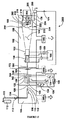
ガスクラスターイオンビームは、ワークピースに照射する目的で、既知の手法に従って生成され、輸送される。照射用GCIB路内の物体を保持するため、および物体を該物体の非常に多数の部分への照射が可能となるように操作するための種々の型のホルダーが当分野において知られている。 A gas cluster ion beam is generated and transported according to known techniques for the purpose of irradiating the workpiece. Various types of holders are known in the art for holding an object in the illumination GCIB path and for manipulating the object so that a very large number of parts of the object can be illuminated.
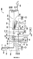
中性粒子ビームは、ワークピースに照射する目的で、本明細書において教示した手法に従って生成され、輸送される。 The neutral particle beam is generated and transported according to the techniques taught herein for the purpose of irradiating the workpiece.
本発明によるビーム改善表面を有する物体は、(例えば、限定されないが)細胞培養、組織培養、外植片培養、組織操作、または他の細胞付着もしくは成長用途が意図される生物学実験器具において使用してもよく、哺乳動物または他の生物学的存在体の体内もしくは身体組織内または身体上もしくは身体組織上に医療的/外科的に埋め込んでもよく、環境試験用途などに使用してもよい。任意選択で、例えば、医療的/外科的埋込みの場合において、ビーム加工表面上への細胞のインビトロ付着がもたらされるように、適用前に物体をさらに加工してもよい。 Objects having a beam improving surface according to the present invention are used in biological laboratory instruments intended for (eg, but not limited to) cell culture, tissue culture, explant culture, tissue manipulation, or other cell attachment or growth applications. It may be implanted medically / surgically in or on the body or body tissue of a mammal or other biological entity, and may be used for environmental testing applications and the like. Optionally, in the case of medical / surgical implantation, for example, the object may be further processed prior to application so as to provide in vitro attachment of cells onto the beam processing surface.
本発明の一実施形態では、加速ガスクラスターイオンビームから、高ビーム純度の中性粒子ガスクラスターおよび/またはモノマービームを誘導するための方法が使用される。中性粒子ガスクラスターおよび/またはモノマービームは、さまざまな型の表面材質および浅い表面下材質の加工に使用され得、一部の用途のための従来のGCIB加工と比べて卓越した性能を発揮し得るものである。これにより、約1eV〜約100eV(あるいはさらに数百eV)の範囲のエネルギーを有する良好に集束された強力中性粒子モノマービームが得られ得る。これは、強力中性粒子ビームを形成するための単純で比較的廉価な装置では可能でなかったエネルギー範囲である。 In one embodiment of the present invention, a method is used for deriving high beam purity neutral particle gas clusters and / or monomer beams from an accelerated gas cluster ion beam. Neutral particle gas clusters and / or monomer beams can be used to process various types of surface and shallow subsurface materials, providing superior performance compared to conventional GCIB processing for some applications. To get. This can result in a well focused intense neutral particle monomer beam having an energy in the range of about 1 eV to about 100 eV (or even several hundred eV). This is an energy range that was not possible with a simple and relatively inexpensive device for forming a strong neutral beam.
このような中性粒子ビームは、まず従来の加速GCIBを形成し、次いで、これを、ビーム内に不純物が導入されない方法および作動条件によって一部または充分に解離させ、次いで、ビームの残りの荷電部分を中性粒子部分から分離することにより形成され、生じた中性粒子ビームをワークピースの加工に使用する。ガスクラスターイオンの解離の度合に応じて、生成された中性粒子ビームは、中性粒子モノマーガスとガスクラスターの混合物であってもよく、本質的にすべて中性粒子モノマーガスからなるものであってもよい。 Such a neutral beam first forms a conventional accelerated GCIB, which is then partially or fully dissociated by the method and operating conditions in which no impurities are introduced into the beam, and then the remaining charge of the beam The resulting neutral particle beam is used to process the workpiece, formed by separating the part from the neutral particle part. Depending on the degree of dissociation of the gas cluster ions, the generated neutral particle beam may be a mixture of neutral particle monomer gas and gas cluster, consisting essentially of neutral particle monomer gas. May be.
本発明の方法によって生成され得る中性粒子ビームの利点は、中性粒子ビームが、荷電イオンビームによって損傷され得るか、あるいは別の様式で有害な影響を受け得る物質(例えば(限定されないが)電気絶縁性材料)を加工するために、イオン化ビームの場合で起こり得るビーム輸送電荷によるこのような材料の表面の帯電のために物質に対して損傷がもたらされることなく、使用され得るということである。中性粒子ビームの使用により、ポリマー、誘電体および/または他の電気絶縁性材料、表面被膜、ならびにイオンビームによって帯電による許容され得ない副次的影響がもたらされ得る他の用途の膜の成功裡のビーム加工が可能となり得る。他の例では、ポリマーまたは他の誘電体材料の中性粒子ビーム誘導性の改良(例えば、滅菌、スムージング、生体適合性の改善、および薬物結合の改善)により、このような材料を医療的埋込みおよび他の医療的/外科的用途に使用することが可能となり得る。さらなる例としては、表面特性(粗さ、平滑性、親水性および生体適合性など)を改善するために使用され得る、ガラス、ポリマーおよびセラミック製のバイオカルチャー実験器具および/または環境サンプリング表面の中性粒子ビーム加工が挙げられる。 The advantage of a neutral beam that can be generated by the method of the present invention is that the neutral beam can be damaged by a charged ion beam or otherwise adversely affected (eg (but not limited to)) Can be used to process electrical insulating materials) without causing damage to the material due to the charging of the surface of such materials by beam transport charges that can occur in the case of ionized beams is there. The use of a neutral beam of polymers, dielectrics and / or other electrically insulating materials, surface coatings, and films of other applications where ion beams can cause unacceptable side effects due to charging. Successful beam processing may be possible. In other examples, neutral particle beam inductive improvements in polymers or other dielectric materials (eg, sterilization, smoothing, improved biocompatibility, and improved drug binding) make such materials medically implantable. And may be usable for other medical / surgical applications. As a further example, in glass, polymer and ceramic bioculture laboratory instruments and / or environmental sampling surfaces that can be used to improve surface properties such as roughness, smoothness, hydrophilicity and biocompatibility. Active particle beam processing.
元のGCIBは荷電状態であるため、これは、所望のエネルギーまで容易に加速され、容易に集束、偏向、走査あるいは別の様式で取り扱われる。荷電イオンが解離された中性粒子ビームから分離されると、中性粒子ビーム粒子は、その初期の軌道を保持している傾向にあり、良好な集束で長距離輸送され得る。 Since the original GCIB is in a charged state, it is easily accelerated to the desired energy and is easily focused, deflected, scanned, or otherwise handled. When charged ions are separated from the dissociated neutral beam, the neutral beam particles tend to retain their initial trajectory and can be transported over long distances with good focusing.
ガスクラスターイオンは、さまざまな理由で、多くの場合、クラスターイオンからのモノマーの蒸発によって解離され得ると考えられる。イオン化装置では、入射加速電子によってエネルギーがクラスターに移動され得るとともに、クラスターのイオン化が誘導され得る。このエネルギー移動によってクラスターは励起状態のままとなり得、それにより、下流でのガスクラスターイオンからの中性粒子モノマーの蒸発がもたらされ得る。あるいはまた、加速ガスクラスターイオンは、残留ガス分子および/または他のクラスターと衝突することがあり得る。このような衝突により、クラスター断片化および/またはエネルギー移動がもたらされ得、続いて、ガスクラスターイオンからの中性粒子モノマーの蒸発がもたらされ得る。 It is believed that gas cluster ions can often be dissociated by evaporation of monomers from the cluster ions for a variety of reasons. In the ionizer, energy can be transferred to the cluster by incident accelerated electrons and ionization of the cluster can be induced. This energy transfer can leave the cluster in an excited state, which can result in the evaporation of neutral monomer from downstream gas cluster ions. Alternatively, the accelerated gas cluster ions can collide with residual gas molecules and / or other clusters. Such collisions can result in cluster fragmentation and / or energy transfer followed by evaporation of neutral particle monomers from gas cluster ions.
解離は、電子との衝突、またはGCIBが形成されたものと同じガスのガス分子(および/またはガスクラスター)との衝突によって誘導されるため、解離プロセスによってビームに寄与する夾雑はない。 Dissociation is induced by collisions with electrons or collisions with gas molecules (and / or gas clusters) of the same gas as the GCIB is formed, so there is no contamination contributing to the beam by the dissociation process.
GCIBのガスクラスターイオンを解離させるために使用され得る機構はいくつか存在する。また、このような機構のいくつかは、中性粒子ガスクラスタービームの中性粒子ガスクラスターを解離させる機能も果たす。ビーム内での衝突に完全に依存して解離をもたらすことにより、他の材料との衝突によるビームの夾雑が回避される。ノズルからの中性粒子ガスクラスタージェットは、電子がクラスターをイオン化するように誘導されるイオン化領域内を進行するため、クラスターは、非イオン化状態のままであり得るか、または1つ以上の電荷の荷電状態を獲得し得る(入射電子によるクラスターからの電子の放出によって)。イオン化装置の作動条件は、ガスクラスターが特定の荷電状態となる尤度に影響を及ぼし、イオン化装置の条件が厳しいほど、高い荷電状態が得られる確率が高くなる。高イオン化効率がもたらされるより厳しいイオン化装置の条件は、高電子束および/または高(制限範囲内)電子エネルギーによってもたらされ得る。ガスクラスターがイオン化されると、これは、典型的にはイオン化装置から引き出され、ビームに集束され、電場内に落下されることによって加速される。加速の量は、加速電場の大きさを制御することにより容易に制御される。典型的な市販のGCIB加工ツールでは、一般的に、約lkV〜30kV(以上)の調整可能な加速ポテンシャルVAccを有する電場中で加速させるガスクラスターイオンが得られる。したがって、単一荷電ガスクラスターイオンでは1〜30keV(またはそれ以上)の範囲のエネルギーが得られ、多重荷電(例えば限定されないが、荷電状態,q=3の電子電荷)ガスクラスターイオンでは3〜90keV(またはそれ以上)の範囲のエネルギーが得られる。他のガスクラスターイオンの荷電状態および加速ポテンシャルについては、クラスター1つあたりの加速エネルギーはq×VAccである。所与のイオン化効率を有する所与のイオン化装置では、ガスクラスターイオンは、ゼロ(イオン化されていない)から6くらいの高値またはそれ以上であり得る数値までの荷電状態の分布を有するものであり、荷電状態の分布のピークは、イオン化装置効率の増大に伴って(電子束およびエネルギーが高いほど)増大する。また、イオン化装置効率が高いほど、イオン化装置内で形成されるガスクラスターイオンの数が増大することになる。多くの場合、GCIB加工の処理量は、イオン化装置を高効率で作動させることによりGCIB電流を増大させると増大する。このような作動のマイナス面は、中間サイズのガスクラスターイオンの高い荷電状態によって該イオンによるくぼみの形成が増大し得ることであり、多くの場合、このようなくぼみの形成は、加工の目的に対して逆効果的に作用し得る。したがって、多くのGCIB表面加工方策では、イオン化装置の作動パラメータの選択は、単にビーム電流を最大にするよりも多くの考慮事項を伴う傾向にある。一部の方法では、「圧力セル」(Swensonらに対する米国特許第7,060,989号参照)の使用を利用することにより、イオン化装置を高いイオン化効率で作動させることが可能であり得るが、高圧の「圧力セル」内でのガスの衝突によってビームエネルギーが緩和されることにより、依然として許容され得るビーム加工性能が得られる。 There are several mechanisms that can be used to dissociate GCIB gas cluster ions. Some of these mechanisms also serve to dissociate neutral particle gas clusters from the neutral particle gas cluster beam. By providing dissociation entirely dependent on collisions within the beam, beam contamination due to collisions with other materials is avoided. The neutral gas cluster jet from the nozzle travels in the ionization region where electrons are induced to ionize the cluster, so that the cluster can remain in an unionized state or one or more of the charges A charged state can be acquired (by emission of electrons from the cluster by incident electrons). The operating conditions of the ionizer affect the likelihood that the gas cluster will be in a particular charged state, and the more severe the conditions of the ionizer, the higher the probability that a higher charged state will be obtained. The more severe ionizer conditions that result in high ionization efficiency can be provided by high electron flux and / or high (within limits) electron energy. When a gas cluster is ionized, it is typically extracted from the ionizer, focused into a beam, and accelerated by being dropped into the electric field. The amount of acceleration is easily controlled by controlling the magnitude of the accelerating electric field. Typical commercial GCIB processing tools generally provide gas cluster ions that are accelerated in an electric field with a tunable acceleration potential VAcc of about 1 kV to 30 kV (or higher). Thus, energies in the range of 1-30 keV (or more) are obtained with single charged gas cluster ions, and 3-90 keV with multi-charged (eg, but not limited to charge state, q = 3 electronic charge) gas cluster ions. Energy in the (or higher) range is obtained. For the charge state and acceleration potential of other gas cluster ions, the acceleration energy per cluster is q × VAcc. For a given ionizer having a given ionization efficiency, the gas cluster ions are those having a charge state distribution from zero (not ionized) to a value that can be as high as 6 or higher, and The peak of the charge state distribution increases with increasing ionizer efficiency (higher electron flux and energy). In addition, the higher the ionizer efficiency, the greater the number of gas cluster ions formed in the ionizer. In many cases, the throughput of GCIB processing increases as the GCIB current is increased by operating the ionizer with high efficiency. The downside of such operation is that the high charge state of intermediate-sized gas cluster ions can increase the formation of indentations by the ions, and in many cases, the formation of such indentations is a process objective. On the other hand, it can act counter-effectively. Thus, in many GCIB surface machining strategies, the selection of ionizer operating parameters tends to involve more considerations than simply maximizing the beam current. In some methods, it may be possible to operate the ionizer with high ionization efficiency by utilizing the use of a “pressure cell” (see US Pat. No. 7,060,989 to Swenson et al.) The beam energy is mitigated by gas collisions within the high pressure “pressure cell”, resulting in still acceptable beam processing performance.
本発明では、イオン化装置を高効率で作動させる(実際には、このような作動は好ましい)というマイナス面はない。イオン化装置を高効率で作動させる場合、イオン化装置によって生成されるガスクラスターイオンには広範な荷電状態が存在し得る。これにより、イオン化装置と加速電極との間の引出し領域内のガスクラスターイオンに、また、下流ビームにも広範な速度がもたらされる。これにより、ビームのガスクラスターイオン間および該イオン同士の衝突頻度の向上がもたらされ得る(一般的に、最大のガスクラスターイオンの高い断片化度がもたらされる)。このような断片化により、ビームのクラスターサイズの再分布がもたらされ、小型クラスターサイズの方向に非対称となり得る。このようなクラスター断片は、その新たなサイズ(個数N)に比例したエネルギーを保持しており、そのため、エネルギー的には小さくなるが、本質的に、最初の断片化されていないガスクラスターイオンの加速度を保持している。速度の保持を伴うエネルギー変化は実験により確認されている(例えば、Toyoda,N.ら,“Cluster size dependence on energy and velocity distributions of gas cluster ions after collisions with residual gas,”Nucl.Instr.& Meth.in Phys.Research B 257 (2007),pp662−665に報告されているとおり)。また、断片化により、クラスター断片内の電荷の再分布がもたらされることもあり得る。いくらかの非荷電断片が生じる可能性があり、多重荷電ガスクラスターイオンは、いくつかの荷電ガスクラスターイオンおよびおそらくいくらかの非荷電断片に断片化され得る。本発明の中性粒子ビームの実施形態の方法では、ビームラインのバックグラウンドガス圧は、良好なGCIB伝達に通常必要とされるものより高い圧力を有するように設定され得る。イオン化装置とワークピースとの間でガスクラスターイオンが充分に短い平均自由路および充分に長い飛行路を有するように該圧力を設定すると、バックグラウンドガス分子との多重衝突が行なわれるはずである。N個のモノマーを含み、qの荷電状態を有し、Vボルトの電場ポテンシャル低下中で加速されたガスクラスターイオンでは、クラスターは、およそqV/NeV/モノマーのエネルギーを有する。最小のガスクラスターイオン以外は、このようなイオンとバックグラウンドガスモノマーとの衝突により、およそqV/NeVがガスクラスターイオンに蓄積されることになる。このエネルギーは、ガスクラスターイオン全体のエネルギーと比べると比較的小さいが、一般的に、クラスターの加熱およびクラスターからのモノマーの蒸発がもたらされる。大型クラスターのこのような衝突ではクラスターはほとんど断片化されず、それよりも加温されるか、またはモノマーの蒸発がもたらされると考えられる。このような蒸発モノマーは、蒸発元のガスクラスターとほぼ同じエネルギーqV/NeVおよびほぼ同じ速度を有する。ガスクラスターイオンからこのような蒸発が起こると、電荷は、残留ガスクラスターイオンとともに残留する確率が高くなる。したがって、一連のバックグラウンドガス衝突後、大型ガスクラスターイオンは、おそらく少量の残留ガスクラスターイオンを伴う一群の同時進行モノマーに縮小され得る。同時進行モノマーはすべて、元のガスクラスターイオンのものとほぼ同じ速度を有し、各々は、およそqV/NeVのエネルギーを有する。小型のガスクラスターイオンでは、バックグラウンドガスモノマーとの衝突エネルギーにより、小型のガスクラスターが完全に激しく解離される可能性があり、このような場合において、生じるモノマーが継続してビームととともに進行するのか、またはビームから放出されるのかは不明である。 In the present invention, there is no downside to operating the ionizer with high efficiency (in practice, such operation is preferable). When the ionizer is operated with high efficiency, there can be a wide range of charge states in the gas cluster ions generated by the ionizer. This provides a wide range of velocities for the gas cluster ions in the extraction region between the ionizer and the acceleration electrode and also for the downstream beam. This can result in improved collision frequencies between and between the gas cluster ions in the beam (typically resulting in a high degree of fragmentation of the largest gas cluster ions). Such fragmentation results in a redistribution of the cluster size of the beam and can be asymmetric in the direction of the small cluster size. Such cluster fragments retain an energy proportional to their new size (number N), so they are smaller in energy, but essentially the first unfragmented gas cluster ion. Holds acceleration. Energy changes with velocity retention have been confirmed by experiments (see, for example, Toyoda, N. et al., “Cluster size dependency on energy and velocities distributions of the custody conditions. in Phys.Research B 257 (2007), pp 662-665). Fragmentation can also result in charge redistribution within cluster fragments. Some uncharged fragments can occur and multiple charged gas cluster ions can be fragmented into several charged gas cluster ions and possibly some uncharged fragments. In the method of the neutral beam embodiment of the present invention, the background gas pressure of the beamline can be set to have a higher pressure than is normally required for good GCIB transmission. Setting the pressure so that the gas cluster ions have a sufficiently short mean free path and a sufficiently long flight path between the ionizer and the workpiece should result in multiple collisions with background gas molecules. For gas cluster ions that contain N monomers, have a charge state of q, and are accelerated in the field potential drop of V volts, the cluster has an energy of approximately qV / NeV / monomer. Except for the smallest gas cluster ion, approximately qV / NeV is accumulated in the gas cluster ion due to the collision between the ion and the background gas monomer. This energy is relatively small compared to the energy of the entire gas cluster ion, but generally results in heating of the cluster and evaporation of the monomer from the cluster. Such collisions of large clusters are thought to result in little clustering of the clusters, resulting in warming or evaporation of the monomer. Such an evaporation monomer has approximately the same energy qV / NeV and approximately the same velocity as the gas cluster from which it is evaporated. When such evaporation occurs from the gas cluster ions, the probability that the charges remain with the remaining gas cluster ions increases. Thus, after a series of background gas collisions, the large gas cluster ions can be reduced to a group of co-running monomers, possibly with a small amount of residual gas cluster ions. All co-promoting monomers have approximately the same rate as that of the original gas cluster ions, each having an energy of approximately qV / NeV. In small gas cluster ions, collision energy with background gas monomers can cause the small gas clusters to dissociate completely and violently, in which case the resulting monomer continues to travel with the beam. It is unclear whether it is emitted from the beam.
GCIBがワークピースに到達する前に、ビーム内の残りの荷電粒子(ガスクラスターイオン、特に、小型および中間サイズのガスクラスターイオンならびに一部の荷電モノマー、しかしながら、残留した大型ガスクラスターイオン(あれば)も含まれる)を中性粒子ビームと分離し、ワークピースの加工のための中性粒子ビームのみを残す。好ましい作動条件のため、中性粒子ビームを、本質的に完全に中性粒子モノマーガスで構成されるように測定しておく。 Before the GCIB reaches the workpiece, the remaining charged particles in the beam (gas cluster ions, especially small and medium sized gas cluster ions and some charged monomers, but residual large gas cluster ions (if any ) Is also separated from the neutral beam, leaving only the neutral beam for workpiece processing. For preferred operating conditions, the neutral particle beam is measured to be essentially completely composed of neutral particle monomer gas.
典型的な作動では、全(荷電+中性粒子)ビームのエネルギーに対する中性粒子ビームのエネルギーの比率は70〜95%の範囲であり、そのため、本発明の方法および装置により、充分加速された荷電ビームの運動エネルギーの大部分を中性粒子ビームの運動エネルギーに変換させることが可能になる。 In typical operation, the ratio of the energy of the neutral beam to the energy of the total (charge + neutral) beam is in the range of 70-95%, so that it is sufficiently accelerated by the method and apparatus of the present invention. It becomes possible to convert most of the kinetic energy of the charged beam into the kinetic energy of the neutral particle beam.
ガスクラスターイオンの解離、したがって、大きな中性粒子モノマービーム束の生成は、1)高加速電圧で作動させること(これにより任意の所与のクラスターサイズのqV/Nが増大する)、2)高いイオン化装置効率で作動させること(これにより任意の所与のクラスターサイズのqV/Nが増大し、引出し領域内でのクラスターイオン同士の衝突が増大する)、3)高いビームライン圧力で、または長ビーム路で作動させること(これにより、任意の所与のサイズのガスクラスターイオンでのバックグラウンドガス衝突の確率が増大する)、および4)高ノズルガス流で作動させること(これにより、GCIB軌道にクラスター化されたガスと、おそらくクラスター化されなかったガスの輸送が増大する)により助長される。引出し領域からワークピースまでのガスクラスターイオンビーム路長に該領域内の圧力を掛け算した積により、発生するガスクラスターイオンの解離の度合が求められる。30kV加速では、1位以上の平均ガスクラスターイオン荷電状態および6×10−3トール−cm(セ氏25度で)の圧力×ビーム路長をもたらすイオン化装置パラメータにより、中性粒子エネルギーモノマーに本質的に充分に解離された中性粒子ビームが得られる(残留荷電イオンとの分離後)。圧力とビーム路長の積をガスの目標厚として特性評価することは簡便で慣用的であり、6×10−3トール−cmは、およそ1.94×1014ガス分子/cm2の目標ガス厚に相当する。例示的な(限定されないが)一実施形態では、バックグラウンドガス圧は6×10−5トールであり、ビーム路長は100cmであり、加速ポテンシャルは30kVであり、中性粒子ビームは、ビーム路の終点でモノマーに本質的に充分に解離されていることが観察される。 The dissociation of gas cluster ions, and hence the generation of a large neutral particle monomer beam bundle, is 1) operated at high acceleration voltages (this increases qV / N for any given cluster size), 2) high Operate with ionizer efficiency (this increases qV / N for any given cluster size and increases collisions between cluster ions in the extraction region), 3) at high beamline pressure or long Operate in the beam path (this increases the probability of background gas collisions with any given size of gas cluster ions), and 4) Operate with a high nozzle gas flow (into the GCIB trajectory) Increased transport of clustered gas and possibly unclustered gas). The degree of dissociation of the generated gas cluster ions is obtained by multiplying the gas cluster ion beam path length from the extraction region to the workpiece by the pressure in the region. At 30 kV acceleration, it is essential for neutral energy monomers due to ionizer parameters that result in an average gas cluster ion charge state of 1 or higher and a pressure × beam path length of 6 × 10 −3 Torr-cm (at 25 degrees Celsius). Is obtained (after separation from residual charged ions). Characterizing the product of pressure and beam path length as the target thickness of the gas is simple and conventional, 6 × 10 −3 Torr-cm is approximately 1.94 × 10 14 gas molecules / cm 2 target gas. Corresponds to thickness. In one exemplary (but not limited to) embodiment, the background gas pressure is 6 × 10 −5 Torr, the beam path length is 100 cm, the acceleration potential is 30 kV, and the neutral beam is It is observed that the monomer is essentially fully dissociated at the end of
中性粒子ビームの測定は、ガスクラスターイオンビームでは簡便な電流測定では行なうことができない。ワークピースに中性粒子ビームを照射する際の線量測定を容易にするため、中性粒子ビーム電流センサーが使用される。中性粒子ビームセンサーは温度センサーであり、ビームまたはビームサンプルを遮る。センサーの温度上昇速度は、センサーのエネルギービーム照射により生じるエネルギー束と関連している。この温度測定は、センサーに対する入射エネルギーの熱再放射による誤差を回避するため、限定的なセンサー温度範囲で行なわなければならない。センサー測定およびビーム電流測定は、互いに相互較正するために使用され得る。 Neutral particle beam measurement cannot be performed with a simple current measurement using a gas cluster ion beam. A neutral beam current sensor is used to facilitate dosimetry when irradiating the workpiece with a neutral beam. Neutral particle beam sensors are temperature sensors that block a beam or beam sample. The temperature rise rate of the sensor is related to the energy flux generated by the energy beam irradiation of the sensor. This temperature measurement must be performed over a limited sensor temperature range to avoid errors due to thermal re-radiation of incident energy to the sensor. Sensor measurements and beam current measurements can be used to cross-calibrate each other.
ガスクラスターイオンビームから誘導された中性粒子ビームの測定値の使用は、線量測定のための熱エネルギーセンサーと組み合わせて、全ガスクラスターイオンビームまたは遮断された部分もしくは方向転換された部分(これは、不可避的にガスクラスターイオンと中性粒子ガスクラスターおよび/または中性粒子モノマーとの混合物を含む)の測定と比較され得、これは、線量測定の目的で、ビーム電流測定を使用することにより以下のとおりに慣用的に測定される。1)線量測定は、ビームの総エネルギーが測定されるため、中性粒子ビームと温度センサーとによって、より厳密となり得る。線量測定に従来のビーム電流測定を使用するGCIBでは、ビームのイオン化部分の寄与のみが測定され、線量測定に使用される。GCIB装置の作動条件に対する分毎および設定毎の変化により、GCIB中の中性粒子モノマーおよびクラスターの量のばらつきがもたらされる。線量測定をビーム電流測定によって行なった場合、このようなばらつきによって加工のばらつきがもたらされ、これは、あまり制御され得ない。2)中性粒子ビームでは、帯電効果によって損傷されることがあり得る任意の材料(例えば、高度に絶縁性の材料および他の材料)が、イオン化ビームによってワークピースに輸送された電荷によるワークピースの帯電を抑制するための標的中和電子源を供給する必要なく加工され得る。使用される場合、標的中和は完璧であることはめったになく、多くの場合、中和電子源それ自体によって、例えば、ワークピースの加熱、電子源における蒸発またはスパッタリングに由来する夾雑などの問題が誘発される。中性粒子ビームでは電荷がワークピースに輸送されないため、このような問題が回避される。ならびに3)エネルギーモノマーイオンを中性粒子ビームから分離する必要がない。従来のGCIBの場合、エネルギーモノマーイオン(および他の小型クラスターイオン)がワークピースに輸送されるリスク(このとき、該イオンが浸透し、深部損傷をもたらす)は大きく、このような粒子をビームから分離するための高価な磁気フィルターが常套的に必要とされる。本発明の中性粒子ビーム装置の場合では、中性粒子ビームを生成させるためにすべてのイオンをビームから分離することにより、すべてのエネルギーモノマー(および他の小型の)イオンが内在的に除去される。 The use of neutral particle beam measurements derived from gas cluster ion beams can be combined with thermal energy sensors for dosimetry in total gas cluster ion beams or blocked or redirected parts (this is , Inevitably compared to measurements of gas cluster ions and neutral particle gas clusters and / or neutral monomer monomers), by using beam current measurement for dosimetry purposes Measured routinely as follows. 1) Dosimetry can be more rigorous due to the neutral particle beam and the temperature sensor because the total energy of the beam is measured. In GCIB using conventional beam current measurement for dosimetry, only the contribution of the ionized portion of the beam is measured and used for dosimetry. Variations in minutes and settings with respect to the operating conditions of the GCIB apparatus result in variations in the amount of neutral monomer and clusters in the GCIB. When dosimetry is performed by beam current measurement, such variations can lead to processing variations that cannot be controlled much. 2) In a neutral particle beam, any material that can be damaged by the charging effect (eg, highly insulating materials and other materials) is transferred to the workpiece by the ionization beam. Can be processed without the need to supply a target neutralizing electron source to suppress the charging of. When used, target neutralization is rarely perfect, and in many cases, the neutralizing electron source itself can cause problems such as workpiece heating, contamination from the electron source, or contamination from sputtering. Be triggered. Neutral particle beams avoid such problems because no charge is transported to the workpiece. And 3) it is not necessary to separate the energetic monomer ions from the neutral beam. In the case of conventional GCIB, there is a high risk that energetic monomer ions (and other small cluster ions) are transported to the workpiece, where the ions penetrate and cause deep damage, and such particles are removed from the beam. Expensive magnetic filters are routinely needed for separation. In the case of the neutral beam device of the present invention, all energy monomer (and other small) ions are inherently removed by separating all ions from the beam to produce a neutral beam. The
本発明とともに本発明の他の目的およびさらなる目的をより良く理解するために、添付の図面を参照する。
いくつかの例示的実施形態を開示し、バイオ活性を向上させるための本発明のGCIBまたは中性粒子ビーム加工法の有益性を享受し得る広範な種々の材質表面を示す。これらの実施例は、本発明の用途が広く、1つまたはいくつかの材質に限定されるものではなく、広範な材質表面に対して広く利用できることを例示するために選択したものである。 Several exemplary embodiments are disclosed to illustrate a wide variety of material surfaces that can benefit from the GCIB or neutral particle beam processing methods of the present invention for enhancing bioactivity. These examples have been selected to illustrate that the present invention is versatile and not limited to one or several materials, but can be widely used on a wide range of material surfaces.
チタンの例示的実施形態
チタン表面の改善を第1の例示的実施形態において開示する。チタンは、多くの場合、哺乳動物への埋込みが意図される医療用物体に使用される材料である。0.01mm厚のチタン薄片試験片を、まず、70%イソプロパノール中で2時間清浄にし、次いで、安全キャビネット内で一晩風乾させた。清浄にしたこのチタン薄片試験片は、通常の大気条件に曝露させておいた任意チタンの場合と同様、不充分であり得、かつ不完全であり得る非常に薄い自然なチタニア表面被膜を有している可能性があることは理解されよう。次いで、薄片試験片を、30kVの加速電圧を使用して加速させたアルゴンGCIBを用いて5×10¹⁴イオン/cm2の線量までGCIB照射するか、または対照として非照射のままにするかのいずれかとした。チタン薄片(照射試験片と対照試験片の両方)を、次いで、0.9cm×0.9cmの正方形に切断し、24ウェルMultiwellTMポリスチレンプレート(BD Falcon 351147)の個々のウェルの底部に配置した(8つの対照正方形および8つのGCIB照射正方形)。骨(hFOB 1.19,ATCC CRL−11372)から誘導したヒト胎児骨芽細胞を継代培養し、およそ3500個の細胞を、10%ウシ胎仔血清(FBS)および0.3mg/mlのG418抗生物質(ジェネテシンとしても知られている)を補給した1mlの(Invitrogen Corp.)ダルベッコ改変イーグル培地栄養混合物F−12(DMEM/F12)中の各チタンの正方形薄片の上面に置き、加湿インキュベータ内で37℃および空気中5%のCO2にてインキュベートした。インキュベーションの1日後および5日後、培地試料を取り出し、CellTiter 96(登録商標)AQueous Cell Proliferation Assay(Promega製)(製造業者の使用説明書に従って使用)を用いて細胞をアッセイした。測定は、Dynex OpsysMR プレートリーダーを490nm波長で用いて行なった。次いで、アッセイ溶液をウェルから取り出し、次いで、ウェル内でチタンの正方形薄片上に−20℃の冷メタノールを配置することにより、チタン薄片と細胞を少なくとも30分間固定させた。固定後、チタンの正方形薄片を、次いで風乾させ、Hitachi TM1000走査電子顕微鏡を用いて、チタンの正方形薄片に接着している骨芽細胞のイメージングを行なった。結果により、1日のインキュベーション後に薄片に接着している骨芽細胞は、対照薄片では694.5細胞+/−164.8細胞であるが、GCIB照射薄片では2082.3細胞+/−609.2細胞に向上することが示された(P<0.03)。5日間のインキュベーション後に増殖した骨芽細胞は、対照では1598.7細胞+/−728.4細胞であったのに対し、GCIB照射薄片では3898.0細胞+/−940.9細胞であった(P<0.003)。
Exemplary Embodiment of Titanium Improvement of the titanium surface is disclosed in a first exemplary embodiment. Titanium is a material often used for medical objects intended for implantation in mammals. A 0.01 mm thick titanium flake specimen was first cleaned in 70% isopropanol for 2 hours and then air dried overnight in a safety cabinet. This cleaned titanium flake specimen has a very thin natural titania surface coating that can be inadequate and incomplete, as with any titanium that has been exposed to normal atmospheric conditions. It will be understood that this is possible. The flake specimens are then either GCIB irradiated to a dose of 5 × 10 14 ions / cm 2 with argon GCIB accelerated using an acceleration voltage of 30 kV or left unirradiated as a control Either. Titanium slices (both irradiated and control specimens) were then cut into 0.9 cm x 0.9 cm squares and placed at the bottom of individual wells of a 24-well Multiwell ™ polystyrene plate (BD Falcon 351147) ( 8 control squares and 8 GCIB irradiated squares). Human fetal osteoblasts derived from bone (hFOB 1.19, ATCC CRL-11372) were subcultured and approximately 3500 cells were transformed into 10% fetal bovine serum (FBS) and 0.3 mg / ml G418 antibiotic. Place on top of each titanium square slice in 1 ml (Invitrogen Corp.) Dulbecco's Modified Eagle Medium Nutrient Mix F-12 (DMEM / F12) supplemented with the substance (also known as Geneticin) and place in a humidified incubator Incubated at 37 ° C. and 5% CO 2 in air. After 1 and 5 days of incubation, media samples were removed and cells were assayed using CellTiter 96® AQueuous Cell Proliferation Assay (Promega) (used according to manufacturer's instructions). Measurements were made using a Dynex Opsys MR plate reader at a wavelength of 490 nm. The assay solution was then removed from the well and the titanium flakes and cells were then fixed for at least 30 minutes by placing -20 ° C. cold methanol on the titanium square flakes in the well. After fixation, the titanium square flakes were then air-dried and osteoblasts adhering to the titanium square flakes were imaged using a
図1は、hFOB 1.19ヒト胎児骨芽細胞が、対照チタン薄片と比べてGCIB照射チタン薄片上に向上した速度で接着し、増殖することを示す図表である。 FIG. 1 is a chart showing that hFOB 1.19 human fetal osteoblasts adhere and proliferate on GCIB irradiated titanium flakes at an increased rate compared to control titanium flakes.
図2は、5日間のインキュベーション後の対照チタン薄片の走査電子顕微鏡写真である。図3は、5日間のインキュベーション後のGCIB照射チタン薄片の走査電子顕微鏡写真である。図2と図3はどちらも、同じ倍率および同じ画像表面積で示している。図2と図3の比較により、GCIB照射チタン薄片(図3)では骨芽細胞付着度が増大していること、ならびにより多くの骨芽細胞が拡延しており、細胞同士が接触している(これは、骨芽細胞および線維芽細胞などの接着依存性細胞における細胞増殖の開始に重要な要素であることが知られている)ようであることが示される。哺乳動物の体内への医療的/外科的埋込み用の物体の形成に使用される材料(チタンなど)へのGCIB照射により、細胞の付着および増殖に対してより補助的(conducive)となる表面の改良がもたらされる。 FIG. 2 is a scanning electron micrograph of a control titanium flake after 5 days of incubation. FIG. 3 is a scanning electron micrograph of GCIB irradiated titanium flakes after 5 days of incubation. 2 and 3 both show the same magnification and the same image surface area. Comparison of FIG. 2 and FIG. 3 shows that the GCIB-irradiated titanium flakes (FIG. 3) have increased osteoblast adhesion and that more osteoblasts have spread and are in contact with each other. (This is known to be an important factor in the initiation of cell proliferation in adhesion-dependent cells such as osteoblasts and fibroblasts). GCIB irradiation of materials (such as titanium) used to form objects for medical / surgical implantation in the mammal's body provides a more conducive surface for cell attachment and proliferation Improvements are brought about.
この効果を、哺乳動物の体内もしくは身体組織内または身体上への埋込みが意図される医療用物体の一体化を、該物体の表面を細胞の付着および増殖に対してより補助的にすることによって改善するために使用することは、1)一体化の向上がもたらされることが所望される埋込み用の物体を特定する工程、2)該物体の全表面にこのような向上が必要であるかどうか、または向上を物体の表面の一部分のみに限定することが好ましいかどうかを判定する工程(例えば、股関節プロテーゼの骨と結合される部分は付着の改善の恩恵を被るが、球体部すなわち臼蓋の摺動部分は細胞付着の増大の恩恵を受けない)、ならびに3)医療用物体の表面の一体化の向上が所望される部分のみにGCIB照射すること、および最後に、該物体(一体化の向上のために改良されたもの)を医療的/外科的に哺乳動物の体内に埋め込む工程を伴う。もちろん、医療用物体の表面のすべての部分が一体化の向上の恩恵を被ることが好ましい場合では、好ましくは該表面のすべての部分にGCIB照射する。 This effect is achieved by making the integration of a medical object intended for implantation in or on the body or body tissue of a mammal more auxiliary to cell attachment and proliferation. Uses to improve include 1) identifying an object for embedding where it is desired to provide improved integration, and 2) whether such enhancement is required on the entire surface of the object. Or determining whether it is preferable to limit the enhancement to only a portion of the surface of the object (e.g., the portion of the hip prosthesis that joins the bone will benefit from improved adhesion, but the sphere or acetabulum The sliding part does not benefit from increased cell attachment), and 3) GCIB irradiation only on the part where improved integration of the surface of the medical object is desired, and finally the object (integrated Those) that had been modified for the above involves medical / surgical burying the body of a mammal. Of course, if it is preferred that all parts of the surface of the medical object benefit from improved integration, preferably all parts of the surface are GCIB irradiated.
任意選択で、照射工程後、埋込み工程の前に、医療用物体の表面上で細胞を(インビトロで)成長させて付着させる工程を含むことにより、一体化をさらに向上させることができる。これは、医療用物体の埋込みが意図される特定の個体から細胞を単離し、培養し、インビトロで付着させることを含むものであってもよく、別の個体から、または幹細胞もしくは他の多能性細胞(同じ種もしくは異なる種のいずれかの哺乳動物由来)から得た細胞を使用することを含むものであってもよい。 Optionally, integration can be further improved by including growing and attaching cells (in vitro) on the surface of the medical object after the irradiation step and before the implantation step. This may include isolating cells from a particular individual intended for implantation of a medical object, culturing, and attaching in vitro, from another individual, or from stem cells or other pluripotent It may include using cells obtained from sex cells (derived from mammals of either the same or different species).
照射工程は、任意選択で、物体の選択された部分にGCIB加工を限定するためのマスクまたは有向ビームまたは他の方法の使用を含んでもよい。 The irradiation step may optionally include the use of a mask or directed beam or other method to limit GCIB processing to selected portions of the object.
先行技術では、微細粗面のチタン表面が骨芽細胞付着に選好的であることが示されている。SLAチタンは、骨インプラントに一般的に使用されている材料である。SLAプロセスにより、親水性が改善されると同時に、表面も微細粗面になる。SLAチタンおよび対照(平滑機械加工)チタン試験片を、GCIB照射ありとなしの両方で比較した。 The prior art has shown that a fine rough titanium surface is preferred for osteoblast attachment. SLA titanium is a commonly used material for bone implants. The SLA process improves hydrophilicity and at the same time makes the surface fine and rough. SLA titanium and control (smooth machined) titanium specimens were compared both with and without GCIB irradiation.
平滑機械加工表面およびSLA表面の両方のチタン試験片(1cm×1cm×0.6mm)を、アルゴンGCIB照射ありとなしの両方で比較した。平滑機械加工表面とSLA表面を、粗さについて原子間力顕微鏡での測定手法によって特性評価した。1平方マイクロメートルの走査面積で評価した2つの型の表面の平均粗さ(Ra)の値を表1に示す。 Titanium specimens (1 cm × 1 cm × 0.6 mm) on both smooth machined and SLA surfaces were compared both with and without argon GCIB irradiation. The smooth machined surface and the SLA surface were characterized for roughness by a measurement technique with an atomic force microscope. Table 1 shows the average roughness (Ra) values of the two types of surfaces evaluated with a scanning area of 1 square micrometer.

平滑機械加工表面とSLA表面は、30kV加速電圧で5×10¹⁴アルゴンクラスター/cm2の線量のGCIBを照射するか、または対照として非照射のままにするかのいずれかとした。チタン片(各条件に対して9つの試験片、合計36個の試験片)を24ウェル皿の個々のウェルに入れ、およそ2500個のヒト一次骨芽細胞を、10%ウシ胎仔血清(FBS)および1%ペニシリン/ストレプトマイシンを補給した1mlの(Invitrogen Corp.)ダルベッコ改変イーグル培地栄養混合物(DMEM)中の各チタン試験片上に配置し、加湿インキュベータ内で37℃および空気中5%のCO2にてインキュベートした。インキュベーション3日後、7日後および10日後、各条件について3つの試験片を培地から取り出し、CellTiter 96(登録商標)Aqueous Cell Proliferation Assay(Promega製)(製造業者の使用説明書に従って使用)を用いて細胞をアッセイした。測定は、Dynex OpsysMR プレートリーダーを490nm波長で用いて行ない、試験片に対する細胞付着を評価した。結果を表2に示す。 The smooth machined surface and the SLA surface were either irradiated with a dose of 5 × 10 14 argon clusters / cm 2 of GCIB at a 30 kV acceleration voltage or left unirradiated as a control. Titanium strips (9 test strips for each condition, 36 test strips total) are placed in individual wells of a 24-well dish, and approximately 2500 human primary osteoblasts are added to 10% fetal bovine serum (FBS). And placed on each titanium specimen in 1 ml (Invitrogen Corp.) Dulbecco's Modified Eagle Medium Nutrient Mixture (DMEM) supplemented with 1% penicillin / streptomycin and placed in a humidified incubator at 37 ° C. and 5% CO 2 in air. And incubated. After 3 days, 7 days and 10 days of incubation, 3 test strips for each condition were removed from the medium and cells were used with CellTiter 96® Aqueous Cell Proliferation Assay (Promega) (used according to manufacturer's instructions). Were assayed. Measurements were made using a Dynax Opsys MR plate reader at a wavelength of 490 nm to assess cell attachment to the specimen. The results are shown in Table 2.
表2に示した結果は、非照射平滑機械加工と非照射SLAチタン表面との間で、細胞増殖にほとんど差はないことを示す。他方で、どちらの場合も(平滑機械加工表面とSLA表面)、増殖は、GCIB照射表面上ではかなり向上したことがわかる。さらに、増殖の改善は、平滑機械加工(Ra=8.38nm)表面上では、SLA(Ra=20.08nm)表面と比べて有意に大きかった。SLAプロセスによる微細粗面は、過去において細胞の付着および増殖に好ましい表面状態とみなされていたが、GCIB照射により、低い粗さ値(Ra<10nm)であっても卓越した結果が得られることが明らかである。 The results shown in Table 2 show that there is little difference in cell proliferation between non-irradiated smooth machining and non-irradiated SLA titanium surfaces. On the other hand, in both cases (smooth machined surface and SLA surface), it can be seen that growth was significantly improved on the GCIB irradiated surface. Furthermore, the growth improvement was significantly greater on the smooth machined (Ra = 8.38 nm) surface compared to the SLA (Ra = 20.008 nm) surface. Micro rough surfaces by the SLA process have been regarded as a favorable surface state for cell attachment and proliferation in the past, but excellent results can be obtained even with low roughness values (Ra <10 nm) by GCIB irradiation. Is clear.
ガラスの例示的実施形態
ガラス表面の改善を第2の例示的実施形態において開示する。ガラスは、多くの場合、生物学実験器具に使用される材料である。また、ガラスおよびガラス状またはガラス様材料は、哺乳動物への埋込みが意図される医療用物体の製作にも使用される。ガラスカバースリップ(Corning Glass 2865−25)の形態の薄いガラス基材を、まず、70%イソプロパノール中で2時間清浄にし、次いで風乾させた。このガラス試験片を、次いで、30kVの加速電圧を使用して加速させたアルゴンGCIBを用いて5×10¹⁴イオン/cm2の線量までGCIB照射するか、または対照として未照射のままにするかのいずれかとした。ガラスカバースリップ(照射試験片と対照試験片の両方)に、次いで、ヒト一次骨芽細胞を40,000細胞/cm2の初期密度にて、10%ウシ胎仔血清(FBS)および1%ペニシリン/ストレプトマイシンを補給したダルベッコ改変イーグル培地栄養混合物(DMEM)中で播種し、加湿インキュベータ内で37℃および空気中5%のCO2にてインキュベートした。ガラスカバースリップを、最初の4時間に毎時間観察してイメージングし(光学顕微鏡検査)、細胞付着を観察した。4時間後、次いで、栄養混合物と非接着細胞を除去し、補給物を添加した新鮮栄養混合物と交換し、インキュベーションを継続した。播種の24時間後と48時間後に、さらなる顕微鏡画像を取得した。
Exemplary Embodiment of Glass Improvement of the glass surface is disclosed in a second exemplary embodiment. Glass is often the material used in biological laboratory instruments. Glass and glassy or glass-like materials are also used to make medical objects intended for implantation in mammals. A thin glass substrate in the form of a glass coverslip (Corning Glass 2865-25) was first cleaned in 70% isopropanol for 2 hours and then air dried. Whether this glass specimen is then GCIB irradiated to a dose of 5 × 10 14 ions / cm 2 with argon GCIB accelerated using an acceleration voltage of 30 kV or left unirradiated as a control Either. Glass coverslips (both irradiated and control specimens) are then subjected to human primary osteoblasts at an initial density of 40,000 cells / cm 2 with 10% fetal bovine serum (FBS) and 1% penicillin / Seeded in Dulbecco's Modified Eagle Medium Nutrient Mix (DMEM) supplemented with streptomycin and incubated in a humidified incubator at 37 ° C. and 5% CO 2 in air. Glass cover slips were observed and imaged every hour for the first 4 hours (light microscopy) to observe cell attachment. After 4 hours, the nutrient mixture and non-adherent cells were then removed and replaced with a fresh nutrient mixture supplemented with supplements and the incubation continued. Additional microscopic images were acquired 24 and 48 hours after seeding.
図4a、図4cおよび図4eは、細胞の播種後4時間、24時間および48時間(それぞれ)の期間のときに取得した対照ガラスカバースリップの光学顕微鏡写真である。図4b、図4dおよび図4fは、同様に細胞の播種後4時間、24時間および48時間(それぞれ)の期間のときに取得したGCIB照射ガラスカバースリップの光学顕微鏡写真である。対照を各時点のGCIB照射表面と比較することにより、ヒト胎児骨芽細胞は、GCIB照射ガラスカバースリップ表面上では非照射対照と比べて、より多くの数が付着し、より良好に増殖することが明白である。 Figures 4a, 4c and 4e are optical micrographs of control glass cover slips obtained during periods of 4 hours, 24 hours and 48 hours (respectively) after cell seeding. FIGS. 4b, 4d and 4f are optical micrographs of GCIB irradiated glass cover slips obtained during the same period of 4 hours, 24 hours and 48 hours (respectively) after cell seeding. By comparing the control with the GCIB irradiated surface at each time point, human fetal osteoblasts will adhere more and grow better on the GCIB irradiated glass coverslip surface than the non-irradiated control. Is obvious.
ポリマーの例示的実施形態
第1のポリマー表面の改善を第3の例示的な実施形態において開示する。ポリマー材料は、多くの場合、生物学実験器具に使用される材料である(例えば、ポリスチレン、ポリプロピレンなど)。また、ポリマー材料は、哺乳動物への埋込みが意図される医療用物体の製作にも使用される。ペトリ皿(Fisher Scientific Fisherbrand 08−757−12)の形態のポリスチレン基材を、30kVの加速電圧を使用して加速させたアルゴンGCIBを用いて5×10¹⁴イオン/cm2の線量までGCIB照射するか、または対照として非照射のままにするかのいずれかとした。さらに、細胞培養皿(BD Biosiences 353003)の形態のポリスチレン基材を、択一的ポリスチレン表面として比較のために使用した。この細胞培養皿は、細胞成長の向上が意図された特別に処理された表面を有する市販のものである。3例のポリスチレン試験片(照射ペトリ皿試験片と対照ペトリ皿試験片の両方、ならびに非照射択一的細胞培養皿)に、次いで、ヒト一次骨芽細胞を2,500細胞/cm2の初期密度にて、10%ウシ胎仔血清(FBS)および1%ペニシリン/ストレプトマイシンを補給したダルベッコ改変イーグル培地栄養混合物(DMEM)中で播種し、加湿インキュベータ内で37℃および空気中5%のCO2にてインキュベートした。3例のポリスチレン試験片を、最初の4時間に毎時間観察してイメージングし(光学顕微鏡検査)、細胞付着を観察した。4時間後、次いで、栄養混合物と非接着細胞を除去し、補給物を添加した新鮮栄養混合物と交換し、インキュベーションを継続した。播種の24時間後と48時間後に、さらなる顕微鏡画像を取得した。
Exemplary Embodiment of Polymer Improvement of the first polymer surface is disclosed in a third exemplary embodiment. The polymeric material is often a material used in biological laboratory instruments (eg, polystyrene, polypropylene, etc.). The polymeric material is also used to make medical objects intended for implantation in mammals. A polystyrene substrate in the form of a Petri dish (Fisher Scientific Fisherbrand 08-757-12) is GCIB irradiated to a dose of 5 × 10 14 ions / cm 2 using argon GCIB accelerated using an acceleration voltage of 30 kV. Or left unirradiated as a control. In addition, a polystyrene substrate in the form of a cell culture dish (BD Biosciences 353003) was used as an alternative polystyrene surface for comparison. This cell culture dish is a commercial one with a specially treated surface intended to improve cell growth. Three polystyrene specimens (both irradiated and control petri dish specimens, as well as non-irradiated alternative cell culture dishes), followed by initial human primary osteoblasts of 2,500 cells / cm 2 At density, seed in Dulbecco's Modified Eagle Medium Nutrient Mix (DMEM) supplemented with 10% fetal bovine serum (FBS) and 1% penicillin / streptomycin, in a humidified incubator to 37 ° C and 5% CO 2 in air. And incubated. Three polystyrene specimens were observed and imaged every hour for the first 4 hours (light microscopy) to observe cell attachment. After 4 hours, the nutrient mixture and non-adherent cells were then removed and replaced with a fresh nutrient mixture supplemented with supplements and the incubation continued. Additional microscopic images were acquired 24 and 48 hours after seeding.
図5a、図5dおよび図5gは、細胞の播種後4時間、24時間および48時間(それぞれ)の期間のときに取得した対照ポリスチレンペトリ皿の表面の光学顕微鏡写真である。図5b、図5eおよび図5hは、同様に細胞の播種後4時間、24時間および48時間(それぞれ)の期間のときに取得したGCIB照射ポリスチレンペトリ皿の光学顕微鏡写真である。図5c、図5fおよび図5iは、この場合も細胞の播種後4時間、24時間および48時間(それぞれ)の期間のときに取得したGCIB照射ポリスチレン細胞培養皿の光学顕微鏡写真である。ペトリ皿対照を、各時点のGCIB照射ペトリ皿表面および非照射細胞培養皿の表面と比較することにより、ヒト胎児骨芽細胞は、GCIB照射ガラスカバースリップ表面上では、非照射ペトリ皿対照または非照射細胞培養皿表面のいずれかと比べて、より多くの数が付着し、より良好に増殖することが明白である。 Figures 5a, 5d and 5g are optical micrographs of the surface of a control polystyrene petri dish obtained during periods of 4 hours, 24 hours and 48 hours (respectively) after cell seeding. Figures 5b, 5e and 5h are optical micrographs of GCIB irradiated polystyrene petri dishes obtained during the same period of 4 hours, 24 hours and 48 hours (respectively) after cell seeding. FIGS. 5c, 5f and 5i are optical micrographs of GCIB irradiated polystyrene cell culture dishes obtained again during periods of 4 hours, 24 hours and 48 hours (respectively) after cell seeding. By comparing the Petri dish controls to the GCIB irradiated Petri dish surface and the surface of the non-irradiated cell culture dish at each time point, the human fetal osteoblasts were not exposed on the GCIB irradiated glass coverslip surface. It is clear that a higher number adheres and grows better compared to any of the irradiated cell culture dish surfaces.
ペトリ皿(Fisher Scientific Fisherbrand 08−757−12)の形態のさらなるポリスチレン基材を一部マスクし、次いで、30kVの加速電圧を使用して加速させたアルゴンGCIBを用いて5×10¹⁴イオン/cm2の線量までGCIB照射した。使用したマスクは、ポリスチレン表面に近接させた非接触型シャドウマスクとした。非マスク部分には全GCIB線量が受容されるが、マスク部分にはGCIB照射は受容されず、したがって、対照表面としての機能を果たした。次いで、ペトリ皿に、ヒト一次骨芽細胞を2,500細胞/cm2の初期密度にて、10%ウシ胎仔血清(FBS)および1%ペニシリン/ストレプトマイシンを補給したダルベッコ改変イーグル培地栄養混合物(DMEM)中で播種し、加湿インキュベータ内で37℃および空気中5%のCO2にてインキュベートした。ポリスチレンペトリ皿を、最初の4時間に毎時間観察し(GCIB照射領域と非照射領域の境界部の光学顕微鏡検査)、細胞付着を観察した。4時間後、次いで、栄養混合物と非接着細胞を除去し、補給物を添加した新鮮栄養混合物と交換し、インキュベーションを継続した。播種の24時間後と48時間後に顕微鏡画像を取得した。 A further polystyrene substrate in the form of a Petri dish (Fisher Scientific Fisherbrand 08-757-12) was partially masked and then 5 × 10 14 ions / cm using argon GCIB accelerated using an acceleration voltage of 30 kV. GCIB irradiation to a dose of 2 . The mask used was a non-contact type shadow mask placed close to the polystyrene surface. The non-masked portion received the entire GCIB dose, but the masked portion received no GCIB irradiation and therefore served as a control surface. The Petri dishes were then loaded with human primary osteoblasts at an initial density of 2,500 cells / cm 2 with Dulbecco's Modified Eagle Medium nutrient mixture (DMEM supplemented with 10% fetal bovine serum (FBS) and 1% penicillin / streptomycin. ) And incubated at 37 ° C. and 5% CO 2 in air in a humidified incubator. The polystyrene petri dishes were observed every hour for the first 4 hours (optical microscopic examination of the boundary between the GCIB irradiated area and the non-irradiated area) to observe cell attachment. After 4 hours, the nutrient mixture and non-adherent cells were then removed and replaced with a fresh nutrient mixture supplemented with supplements and the incubation continued. Microscopic images were acquired 24 and 48 hours after sowing.
図6aおよび図6bは、細胞の播種後24時間および48時間(それぞれ)の期間のときに取得し、マスクされた非照射領域とマスクされていないGCIB照射領域の境界部を観察した一部マスクされたポリスチレンペトリ皿の光学顕微鏡写真である。GCIB照射領域は各図6aおよび図6bの左側であり、非照射対照領域は各図6aおよび図6bの右側である。両時点の非照射領域とGCIB照射領域を比較することにより、ヒト胎児骨芽細胞は、ポリスチレン表面のGCIB照射部分上では非照射(マスク)部分と比べて、より多くの数が付着し、より良好に増殖することが明白である。 FIGS. 6a and 6b are partial masks obtained during periods of 24 hours and 48 hours (respectively) after cell seeding and observing the boundary between a masked non-irradiated region and an unmasked GCIB irradiated region It is the optical microscope photograph of the done polystyrene petri dish. The GCIB irradiated area is on the left side of each of FIGS. 6a and 6b, and the non-irradiated control area is on the right side of each of FIGS. 6a and 6b. By comparing the non-irradiated area and the GCIB irradiated area at both time points, human fetal osteoblasts adhere more on the GCIB irradiated part of the polystyrene surface than the non-irradiated (masked) part, and more It is clear that it grows well.
第2のポリマー表面の改善を第4の例示的実施形態において開示する。細片(長さ30mm×幅10mm×厚さ1.5mm)の形態のポリテトラフルオロエチレン(PTFE)基材を半分マスクし、30kVの加速電圧を使用して加速させたアルゴンGCIBを用いて5×10¹⁴イオン/cm2の線量までGCIB照射するか、または対照として非照射のままにした。使用したマスクは、PTFE表面に近接させた非接触型シャドウマスクとした。非マスク表面部分には全GCIB線量が受容されるが、マスク表面部分にはGCIB照射は受容されず、したがって、対照表面としての機能を果たした。ブタ一次線維芽細胞を新鮮な前靭帯から収集した。PTFE表面全体(照射部分と対照部分)に、5000細胞/cm2の初期密度にてこのブタ一次線維芽細胞を、10%ウシ胎仔血清(FBS)および1%ペニシリン/ストレプトマイシンを補給したダルベッコ改変イーグル培地栄養混合物(DMEM)中で播種して24時間付着させ、加湿インキュベータ内で37℃にてインキュベートした。24時間後、培地を除去し、細胞を1×リン酸緩衝生理食塩水で手短にすすぎ洗浄し、メタノール(セ氏−20度で予備冷却)中で1時間固定した。GCIB照射部分とGCIB非照射対照部分のPTFE表面の各々のイメージングを、Hitachi TM−1000走査電子顕微鏡を用いて行なった。結果により、PTFE表面のGCIB照射部分とGCIB非照射部分(対比)間に細胞付着の明白な相違がみられることが示された。 A second polymer surface improvement is disclosed in a fourth exemplary embodiment. A polytetrafluoroethylene (PTFE) substrate in the form of a strip (length 30 mm × width 10 mm × thickness 1.5 mm) is masked in half and 5 using argon GCIB accelerated using an acceleration voltage of 30 kV. GCIB irradiation to a dose of × 10 14 ions / cm 2 or left unirradiated as a control. The mask used was a non-contact type shadow mask placed close to the PTFE surface. The non-mask surface portion received the entire GCIB dose, but the mask surface portion received no GCIB irradiation and therefore served as a control surface. Porcine primary fibroblasts were collected from fresh anterior ligaments. Dulbecco's modified eagle supplemented with 10% fetal bovine serum (FBS) and 1% penicillin / streptomycin at the initial density of 5000 cells / cm 2 on the entire PTFE surface (irradiated part and control part) Seeds in medium nutrient mixture (DMEM) were allowed to attach for 24 hours and incubated at 37 ° C. in a humidified incubator. After 24 hours, the medium was removed and the cells were briefly rinsed with 1 × phosphate buffered saline and fixed in methanol (precooled at −20 degrees Celsius) for 1 hour. Imaging of the PTFE surface of the GCIB irradiated portion and the GCIB non-irradiated control portion was performed using a Hitachi TM-1000 scanning electron microscope. The results showed that there was a clear difference in cell attachment between the GCIB irradiated part and the non-GCIB irradiated part (contrast) on the PTFE surface.
図7aは、細胞の播種の24時間後に取得したPTFE基材のGCIB非照射対照表面の走査電子顕微鏡写真である。図7bは、同様に細胞の播種の24時間後に取得したPTFE基材のGCIB照射表面の走査電子顕微鏡写真である(どちらも固定後)。 FIG. 7a is a scanning electron micrograph of a PTIB-based GCIB non-irradiated control surface obtained 24 hours after cell seeding. FIG. 7b is a scanning electron micrograph of the GCIB-irradiated surface of the PTFE base material obtained after 24 hours of cell seeding (both after fixation).
図7aは、細胞が付着したのはPTFE表面のGCIB非照射対照部分の1%未満であることを示す。 FIG. 7a shows that the cells attached were less than 1% of the GCIB non-irradiated control portion of the PTFE surface.
図7bは、細胞がPTFE表面のGCIB照射部分のほぼ100%付着したことを示す。 FIG. 7b shows that the cells attached almost 100% of the GCIB irradiated part of the PTFE surface.
表面上への細胞付着に影響を及ぼすこの能力は、限定的な領域のみでの細胞成長が所望される多くの用途に極めて有用であり得る。例としては、心血管用ステント(これは、管腔側表面にGCIB照射され得、再内皮化が可能になり、反管腔側の表面は、インタクトな(非照射)表面に維持され、平滑筋成長およびプラーク形成が抑制される)が挙げられる。このようなステントは、PTFE、コバルト−クロム合金、または他の材料から製作され得る。任意選択で、このようなステントの反管腔側表面を、反管腔側表面上での平滑筋(および/または他の細胞)の成長が抑止され、したがって再狭窄のリスクを低減させるための既知の技術を用いて薬物コーティングしてもよい。他の例の用途としては、神経再生を可能にするためのシリコーンゴムチューブのGCIB照射、およびこのような他のものが挙げられる。 This ability to affect cell attachment on a surface can be extremely useful in many applications where cell growth in only a limited area is desired. As an example, a cardiovascular stent (which can be GCIB irradiated to the luminal surface, allowing re-endothelialization, the antiluminal surface being maintained on an intact (non-irradiated) surface, smooth Muscle growth and plaque formation are suppressed). Such stents can be made from PTFE, cobalt-chromium alloys, or other materials. Optionally, the anti-lumen surface of such a stent is used to inhibit the growth of smooth muscle (and / or other cells) on the anti-lumen surface, thus reducing the risk of restenosis. Drug coating may be performed using known techniques. Other example applications include GCIB irradiation of silicone rubber tubes to allow nerve regeneration, and others such.
第3のポリマー表面の改善を第5の例示的実施形態において開示する。ポリエーテルエーテルケトン(PEEK)は、多くの外科的埋込み用途において、好都合なチタン代替物となってきている。PEEKではチタンよりも大きな柔軟性の度合がもたらされ、これは、多くの用途(例えば、脊椎固定ケージの製作)において望ましい。PEEKは、本質的に純粋な形態で使用され得るが、炭素繊維強化形態(および場合によっては、他の材料とのコポリマー形態)も使用されている。PEEKの不都合点は、いくつかの他の材料(例えば、チタン)ほど細胞適合性またはバイオ活性でないことである。したがって、PEEKインプラントは、必ずしも所望のとおりに一体化されるとは限らない。 A third polymer surface improvement is disclosed in a fifth exemplary embodiment. Polyetheretherketone (PEEK) has become a convenient titanium replacement in many surgical implantation applications. PEEK provides a greater degree of flexibility than titanium, which is desirable in many applications (eg, making spinal fixation cages). PEEK can be used in an essentially pure form, but carbon fiber reinforced forms (and in some cases copolymer forms with other materials) have also been used. The disadvantage of PEEK is that it is not as cytocompatible or bioactive as some other materials (eg, titanium). Thus, PEEK implants are not always integrated as desired.
PEEKの適合性およびバイオ活性は、GCIB照射によって改善され、該材料は、細胞付着および一体化が所望される状況での外科的埋込みに対してより適したものとなる。0.005インチ厚のPEEKシートを、70%イソプロピルアルコール中に2時間入れた後、再蒸留水中で4回洗浄し(各洗浄は15分間)、その後、生物学用ドラフト内でUV光に15分間置くことによって事前に清浄にした。次いで、PEEKシートにアルゴンGCIBを5×1014アルゴンガスクラスターイオン/cm2の線量まで照射し(または対照として未照射のままにし)、1/2インチの直径の円板に切断し、次いで、さらに15分間UV照射した。このPEEK円板を、24ウェル滅菌ポリスチレンプレートの個々のウェルに入れた(プレートのプラスチックに細胞が付着するのを回避するために処理された非組織培養)。ヒト骨芽細胞をPEEK円板の表面上に3,000細胞/mlの濃度で、10%ウシ胎仔血清(FBS)および1%ペニシリン/ストレプトマイシンを補給したダルベッコ改変イーグル培地栄養混合物(DMEM)中で播種し、加湿インキュベータ内で37℃および空気中5%のCO2にてインキュベートした。PEEK円板1つあたり1mlの細胞懸濁液を播種し、条件(照射/非照射)ならびにインキュベーション時間(4、7および11日)あたりn=3とした。すべてのPEEK円板において細胞を24時間付着させ、次いで、培地および非付着細胞(あれば)を吸引し、新鮮培地と交換し、プレートをインキュベータに戻した。続いて、細胞を11日間までインキュベートしながら、PEEK円板の表面上に付着させ、増殖させた。各実験期間(播種の4日後、7日後および11日後)に、PEEK試験片を顕微鏡で観察し、PEEK表面に本質的に100%の細胞付着が起こったことを確認し、各PEEK円板をそのウェルと培地から取り出し、事前に細胞も培地も含めていない新たなウェルに入れた。MTS/PMS増殖アッセイ試薬を製造業者の使用説明書(Promega,G5421)どおりに加えた新鮮培地を細胞アッセイに使用し、細胞アッセイではプレートリーダー(490nmの波長で作動)を用いて測定した。吸光度の読み値を、MTS/PMSアッセイの製造業者の手順に従って既知細胞数について事前に作成した較正曲線に基づいて細胞数に変換し、各PEEK試験片上の付着細胞数を特性評価した。各アッセイ後、細胞が付着したPEEK試験片を検査し、PEEK上の細胞付着および細胞成長を走査電子顕微鏡検査およびDAPI蛍光染色(光学蛍光顕微鏡検査によってイメージング)によって確認した。 The compatibility and bioactivity of PEEK is improved by GCIB irradiation, making the material more suitable for surgical implantation in situations where cell attachment and integration is desired. A 0.005 inch thick PEEK sheet was placed in 70% isopropyl alcohol for 2 hours, then washed 4 times in double distilled water (15 minutes for each wash), and then subjected to 15 hours of UV light in a biological fume hood. Pre-cleaned by placing for a minute. The PEEK sheet was then irradiated with argon GCIB to a dose of 5 × 10 14 argon gas cluster ions / cm 2 (or left unirradiated as a control), cut into 1/2 inch diameter discs, then Further UV irradiation was performed for 15 minutes. This PEEK disc was placed into individual wells of a 24-well sterile polystyrene plate (non-tissue culture treated to avoid cell attachment to the plastic on the plate). Human osteoblasts in a Dulbecco's modified Eagle's medium nutrient mixture (DMEM) supplemented with 10% fetal bovine serum (FBS) and 1% penicillin / streptomycin at a concentration of 3,000 cells / ml on the surface of the PEEK disc Seeded and incubated in a humidified incubator at 37 ° C. and 5% CO 2 in air. One ml of cell suspension was seeded per PEEK disc, with n = 3 per condition (irradiated / non-irradiated) and incubation time (4, 7 and 11 days). Cells were allowed to attach for 24 hours in all PEEK discs, then media and non-adherent cells (if any) were aspirated and replaced with fresh media and plates were returned to the incubator. Subsequently, the cells were allowed to attach and grow on the surface of the PEEK disc while incubating for up to 11 days. During each experimental period (4 days, 7 days and 11 days after seeding), PEEK specimens were observed under a microscope to confirm that essentially 100% cell attachment had occurred on the PEEK surface, and each PEEK disc was The wells were removed from the medium and placed in new wells that did not contain cells or medium in advance. Fresh media supplemented with MTS / PMS proliferation assay reagents as per manufacturer's instructions (Promega, G5421) was used for cell assays, which were measured using a plate reader (operating at a wavelength of 490 nm). Absorbance readings were converted to cell numbers based on a calibration curve previously generated for known cell numbers according to the MTS / PMS assay manufacturer's procedure, and the number of adherent cells on each PEEK specimen was characterized. After each assay, PEEK specimens with attached cells were examined and cell attachment and cell growth on PEEK was confirmed by scanning electron microscopy and DAPI fluorescence staining (imaging by optical fluorescence microscopy).
図8は、上記のPEEKでの増殖および付着実験の結果をまとめた図表である。バー(標準偏差をエラーバーで示す)は、播種後1日、7日および11日の期間のときの非照射対照PEEK表面とGCIB照射PEEK表面のMTS/PMS増殖アッセイの結果を示す。11日目までに、GCIB照射PEEK上では(4,975±397細胞)、対照(2,675±278細胞、p<0.028)と比べて有意な細胞増殖の増大がみられる。この結果は、PEEK表面のGCIB照射により、GCIB非照射PEEK表面と比べて細胞の付着および増殖の向上がもたらされることを示す。 FIG. 8 is a table summarizing the results of proliferation and adhesion experiments with PEEK. Bars (standard deviations are shown as error bars) show the results of MTS / PMS proliferation assays of unirradiated control and GCIB irradiated PEEK surfaces during the 1 day, 7 day and 11 day periods after seeding. By day 11, there is a significant increase in cell proliferation on GCIB irradiated PEEK (4,975 ± 397 cells) compared to control (2,675 ± 278 cells, p <0.028). This result shows that GCIB irradiation of the PEEK surface results in improved cell attachment and proliferation compared to the GCIB non-irradiated PEEK surface.
アモルファス石英の例示的実施形態
アモルファス石英の表面加工を第6の例示的な実施形態において開示する。アモルファス石英材料は、多くの場合、生物学実験器具に使用される材料であり、また、哺乳動物への埋込みが意図される医療用物体の製作にも使用される。アモルファス石英は、細胞の表面付着および増殖に非常に好都合な材料であることが知られている。清浄な滅菌アモルファス石英基材を一部マスクし、次いで、30kVの加速電圧を使用して加速させたアルゴンGCIBを用いて5×10¹⁴イオン/cm2の線量までGCIB照射した。使用したマスクは、石英表面に近接させた非接触型シャドウマスクとした。非マスク部分には全GCIB線量が受容されるが、マスク部分にはGCIB照射は受容されず、したがって、対照表面としての機能を果たした。ブタ一次線維芽細胞を新鮮な前靭帯から収集した。アモルファス石英表面に、5,000細胞/cm2の初期密度にてこのブタ一次線維芽細胞を、10%ウシ胎仔血清(FBS)および1%ペニシリン/ストレプトマイシンを補給したダルベッコ改変イーグル培地栄養混合物(DMEM)中で播種し、加湿インキュベータ内で37℃および空気中5%のCO2にてインキュベートした。4時間後、次いで、培地と非接着細胞を除去し、新鮮培地と交換し、インキュベーションを継続した。表面を最初の4時間に毎時間、さらに、最初の播種の6時間後、24時間後および48時間後に観察し、イメージングした。
Exemplary Embodiment of Amorphous Quartz Surface processing of amorphous quartz is disclosed in a sixth exemplary embodiment. Amorphous quartz material is often the material used in biological laboratory instruments and is also used to make medical objects intended for implantation in mammals. Amorphous quartz is known to be a very convenient material for cell surface attachment and growth. The clean sterile amorphous quartz substrate was partially masked and then GCIB irradiated to a dose of 5 × 10 14 ions / cm 2 using argon GCIB accelerated using an acceleration voltage of 30 kV. The mask used was a non-contact type shadow mask placed close to the quartz surface. The non-masked portion received the entire GCIB dose, but the masked portion received no GCIB irradiation and therefore served as a control surface. Porcine primary fibroblasts were collected from fresh anterior ligaments. Dulbecco's modified Eagle's medium nutrient mixture (DMEM) supplemented with 10% fetal bovine serum (FBS) and 1% penicillin / streptomycin on an amorphous quartz surface at an initial density of 5,000 cells / cm 2. ) And incubated at 37 ° C. and 5% CO 2 in air in a humidified incubator. After 4 hours, the medium and non-adherent cells were then removed and replaced with fresh medium and the incubation continued. The surface was observed and imaged every hour for the first 4 hours, and 6 hours, 24 hours and 48 hours after the initial seeding.
図9は、細胞の播種の24時間後に取得し、マスクされた非照射領域とマスクされていないGCIB照射領域の境界部を観察した一部マスクされたアモルファス石英基材の光学顕微鏡写真である。結果により、線維芽細胞は、アモルファス石英表面のGCIB照射側に優先的に、中程度に付着することが示される。GCIB照射領域は図9の左側であり、非照射対照領域は図9の右側である。 FIG. 9 is an optical micrograph of a partially masked amorphous quartz substrate obtained 24 hours after cell seeding and observing the boundary between the masked non-irradiated region and the unmasked GCIB irradiated region. The results show that fibroblasts adhere to the medium preferentially on the GCIB irradiation side of the amorphous quartz surface. The GCIB irradiated area is on the left side of FIG. 9, and the non-irradiated control area is on the right side of FIG.
結晶性サファイアの例示的実施形態
(単結晶)結晶性サファイア表面の改善を第7の例示的実施形態において開示する。清浄な滅菌結晶性サファイア基材を一部マスクし、次いで、30kVの加速電圧を使用して加速させたアルゴンGCIBを用いて5×10¹⁴イオン/cm2の線量までGCIB照射した。使用したマスクは、サファイア表面に近接させた非接触型シャドウマスクとした。非マスク部分には全GCIB線量が受容されるが、マスク部分にはGCIB照射は受容されず、したがって、対照表面としての機能を果たした。ブタ一次線維芽細胞を新鮮な前靭帯から収集した。結晶性サファイア表面に、5,000細胞/cm2の初期密度にてこのブタ一次線維芽細胞を、10%ウシ胎仔血清(FBS)および1%ペニシリン/ストレプトマイシンを補給したダルベッコ改変イーグル培地栄養混合物(DMEM)中で播種し、加湿インキュベータ内で37℃および空気中5%のCO2にてインキュベートした。4時間後、次いで、培地と非接着細胞を除去し、新鮮培地と交換し、インキュベーションを継続した。表面を最初の4時間に毎時間、さらに、最初の播種の6時間後、24時間後および48時間後に観察し、イメージングした。
Example Embodiment of Crystalline Sapphire An improvement of a (single crystal) crystalline sapphire surface is disclosed in a seventh example embodiment. The clean sterile crystalline sapphire substrate was partially masked and then GCIB irradiated to a dose of 5 × 10 14 ions / cm 2 using argon GCIB accelerated using an acceleration voltage of 30 kV. The mask used was a non-contact type shadow mask placed close to the sapphire surface. The non-masked portion received the entire GCIB dose, but the masked portion received no GCIB irradiation and therefore served as a control surface. Porcine primary fibroblasts were collected from fresh anterior ligaments. Dulbecco's modified Eagle medium nutrient mixture supplemented with 10% fetal bovine serum (FBS) and 1% penicillin / streptomycin on a crystalline sapphire surface at an initial density of 5,000 cells / cm 2 ( DMEM) and incubated in a humidified incubator at 37 ° C. and 5% CO 2 in air. After 4 hours, the medium and non-adherent cells were then removed and replaced with fresh medium and the incubation continued. The surface was observed and imaged every hour for the first 4 hours, and 6 hours, 24 hours and 48 hours after the initial seeding.
図10は、細胞の播種の24時間後に取得し、マスクされた非照射領域とマスクされていないGCIB照射領域の境界部を観察した一部マスクされた結晶性サファイア基材の光学顕微鏡写真である。GCIB照射領域は図10の左側であり、非照射対照領域は図10の右側である。非照射領域とGCIB照射領域を比較することにより、ブタ線維芽細胞は、結晶性サファイア表面のGCIB照射部分において非照射(マスク)部分と比べて、より多くの数が付着し、より良好に増殖することが明白である。 FIG. 10 is an optical micrograph of a partially masked crystalline sapphire substrate obtained 24 hours after cell seeding and observing the boundary between a masked non-irradiated region and an unmasked GCIB irradiated region. . The GCIB irradiated area is on the left side of FIG. 10, and the non-irradiated control area is on the right side of FIG. By comparing the non-irradiated region and the GCIB irradiated region, porcine fibroblasts adhere more in the GCIB irradiated part of the crystalline sapphire surface than the non-irradiated (masked) part and proliferate better It is obvious to do.
サファイアなどの結晶性物質にGCIB照射することにより、非常に薄い表面層(数十オングストローム)の一部または完全なアモルファス化がもたらされると考えられる。なんら特定の理論に拘束されることを望まないが、該照射によってもたらされるアモルファス化表面改良が、細胞の付着および増殖の改善に寄与しているようである。この改善に寄与し得る他の考えられ得る機構は、材料の表面のぬれ性、親水性および/または表面荷電状態の改良の増大である。 It is believed that GCIB irradiation of a crystalline material such as sapphire results in part or complete amorphization of a very thin surface layer (tens of angstroms). Without wishing to be bound by any particular theory, it appears that the amorphized surface modification provided by the irradiation contributes to improved cell attachment and proliferation. Another possible mechanism that can contribute to this improvement is an increase in surface wettability, hydrophilicity and / or surface charge state of the material.
ポリマーフィラメント/ポリマー繊維の例示的実施形態
繊維は、織ること、編むこと、および/または他の不織手法によってポリマーまたはコポリマーの繊維で形成されたものであり得る。特定のポリマー繊維(最も顕著には、ポリエチレンテレフタレート)は、血管移植片の作製に特に好適な繊維である。また、織物ポリエチレンテレフタレート(場合によっては、ポリ(エチレンテレフタレート)と表記され、PETまたはPETEと略記される)繊維は、その商標名の1つであるダクロンと称されることもあり得、血管移植片の製作用材料として一般的に使用されている。第8の例示的実施形態では、織物ポリエチレンテレフタレート(PETE)繊維の表面の改善を開示する。PETE繊維から製作された血管移植片は、場合によっては、血液の喪失を低減させるためにタンパク質(コラーゲンもしくはアルブミンなど)で表面コーティングされる、および/または移植片の感染を抑制するために抗生物質で表面コーティングされる。薬理学的または生物学的試薬の使用によって再狭窄を低減させるために設計されるストラテジーのほとんどは、繊維表面上での血管平滑筋細胞増殖の直接的な抑止を伴うものである。しかしながら、択一法としては、平滑筋細胞増殖が、損傷部位および移植片部位での再内皮化の特異的助長によって間接的に抑止され得る。過去において、再内皮化は、多くの場合で低速または不完全であった。この実施形態において、本発明者らは、非表面コーティング織物PETE繊維材料のGCIB照射を評価し、該材料がよりバイオ活性となり、再内皮化の助長に対してより好適になることを示した。
Exemplary Embodiments of Polymer Filament / Polymer Fibers The fibers can be those formed of polymer or copolymer fibers by weaving, knitting, and / or other non-woven techniques. Certain polymer fibers (most notably polyethylene terephthalate) are particularly suitable fibers for making vascular grafts. In addition, a woven polyethylene terephthalate (in some cases, expressed as poly (ethylene terephthalate), abbreviated as PET or PETE) fiber may be referred to as Dacron, which is one of its trade names. It is commonly used as a piece production material. In an eighth exemplary embodiment, surface improvements of woven polyethylene terephthalate (PETE) fibers are disclosed. Vascular grafts made from PETE fibers are optionally surface coated with a protein (such as collagen or albumin) to reduce blood loss and / or antibiotics to control graft infection With surface coating. Most strategies designed to reduce restenosis through the use of pharmacological or biological reagents involve direct inhibition of vascular smooth muscle cell proliferation on the fiber surface. However, as an alternative, smooth muscle cell proliferation can be indirectly inhibited by the specific promotion of re-endothelialization at the injury and graft sites. In the past, reendothelialization has often been slow or incomplete. In this embodiment, we evaluated the GCIB irradiation of the non-surface coated textile PETE fiber material and showed that the material became more bioactive and more suitable for promoting re-endothelialization.
織物PETE繊維を15mm×30mm小片に切断した。この小片の半分をマスクし、30kVの加速電圧を使用して加速させたアルゴンGCIBを用いて5×1014イオン/cm2の線量までGCIB照射した。使用したマスクは、PETE繊維表面に近接させ、該繊維小片の各々の片側の半分を覆う非接触型シャドウマスクとした。非マスク表面部分には全GCIB線量が受容されるが、マスク表面部分にはGCIB照射は受容されず、したがって、対照表面としての機能を果たした。この繊維小片を個々のペトリ皿に入れ、マウス内皮生細胞(EOMA細胞株)を、PETE繊維表面上の全体(照射部分と対照部分)に50,000細胞/繊維小片の初期密度にて播種し、加湿インキュベータ内で37℃にてインキュベーション中に、10%ウシ胎仔血清(FBS)および1%ペニシリン/ストレプトマイシンを補給したダルベッコ改変イーグル培地栄養混合物(DMEM)中で24時間付着させた。24時間後、培地と非接着細胞を除去した。メタノール(セ氏−20度で1時間予備冷却)をPETE繊維上に10分間配置し、接着細胞を固定させた。次いで、繊維および接着したマウス内皮細胞のイメージングを走査電子顕微鏡によって行なった。マウス内皮細胞が付着したPETE繊維のGCIB照射部分と非照射対照部分の両方の表面領域のイメージングをHitachi TM−1000走査電子顕微鏡を用いて行なった。結果により、PETE織物繊維表面のGCIB照射部分とGCIB非照射部分間に細胞付着の明白な相違がみられることが示された。 Woven PETE fibers were cut into 15 mm x 30 mm pieces. Half of this piece was masked and irradiated with GCIB to a dose of 5 × 10 14 ions / cm 2 using argon GCIB accelerated using an acceleration voltage of 30 kV. The mask used was a non-contact type shadow mask that was brought close to the PETE fiber surface and covered half of each side of the fiber piece. The non-mask surface portion received the entire GCIB dose, but the mask surface portion received no GCIB irradiation and therefore served as a control surface. The fiber pieces are placed in individual Petri dishes and seeded with live mouse endothelial cells (EOMA cell line) on the entire PETE fiber surface (irradiated part and control part) at an initial density of 50,000 cells / fiber piece. During incubation at 37 ° C. in a humidified incubator, they were allowed to adhere for 24 hours in Dulbecco's modified Eagle medium nutrient mixture (DMEM) supplemented with 10% fetal bovine serum (FBS) and 1% penicillin / streptomycin. After 24 hours, media and non-adherent cells were removed. Methanol (precooled at −20 degrees Celsius for 1 hour) was placed on PETE fibers for 10 minutes to fix adherent cells. The fibers and adhered mouse endothelial cells were then imaged by scanning electron microscope. Imaging of the surface areas of both GCIB irradiated and non-irradiated control portions of PETE fibers with mouse endothelial cells attached was performed using a Hitachi TM-1000 scanning electron microscope. The results showed that there was a clear difference in cell attachment between the GCIB irradiated and non-GCIB irradiated portions of the PETE fabric fiber surface.
図11は、マウス内皮細胞の播種の24時間後に作製されたPETE繊維表面の処理小片の走査電子顕微鏡写真である(メタノール固定後)。画像の左側のPETE繊維部分は、播種前に照射されなかったPETE繊維のマスク部分である。画像の右側のPETE繊維部分は、細胞の播種前にGCIB照射を受けた部分である。 FIG. 11 is a scanning electron micrograph (after methanol fixation) of a treated piece on the surface of PETE fibers prepared 24 hours after seeding of mouse endothelial cells. The PETE fiber part on the left side of the image is a mask part of PETE fiber that was not irradiated before sowing. The PETE fiber part on the right side of the image is a part that has been subjected to GCIB irradiation before cell seeding.
図11は、マウス内皮細胞による再内皮化が、PETE繊維のGCIB照射部分で非照射対照部分よりも有意にさらに進行したことを示す。EOMA細胞は、PETE繊維のGCIB照射を受けた部分に優先的に接着した。 FIG. 11 shows that re-endothelialization by mouse endothelial cells progressed significantly further in the GCIB irradiated part of the PETE fiber than in the non-irradiated control part. EOMA cells preferentially adhered to the portions of PETE fibers that had been subjected to GCIB irradiation.
コバルト−クロム合金の例示的実施形態
コバルト−クロム合金表面の改善を第9の例示的実施形態において開示する。コバルト−クロム合金は、多くの場合、哺乳動物への埋込みが意図される医療用物体(例えば、血管用ステント)に使用される材料である。コバルト−クロムクーポンを、まず、70%イソプロパノール中で2時間清浄にした後、再蒸留水中で4回洗浄し(各洗浄は15分間)、その後、生物学用ドラフト内でUV光に15分間置いた。次いで、このコバルト−クロム合金クーポンを、30kVの加速電圧を使用して加速させたアルゴンGCIBを用いて5×10¹⁴イオン/cm2の線量までGCIB照射するか、または対照として非照射のままにするかのいずれかとした。次いで、コバルト−クロム合金クーポン(照射試験片と対照試験片の両方)を、24ウェルMultiwellTMポリスチレンプレート(BD Falcon 351147)の個々のウェル(3例の対照クーポンおよび3例のGCIB照射クーポン)の底部に配置した。1mlの細胞懸濁液(マウス内皮生細胞(EOMA細胞株),2,000細胞/ml)を各コバルト−クロム合金クーポン上に播種し、条件(照射/非照射)あたりn=3とした。播種した細胞は、加湿インキュベータ内で37℃にてインキュベーション中、10%ウシ胎仔血清(FBS)および1%ペニシリン/ストレプトマイシンを補給したダルベッコ改変イーグル培地栄養混合物(DMEM)中に懸濁状態とした。
Exemplary Embodiment of Cobalt-Chromium Alloy Improvement of the cobalt-chromium alloy surface is disclosed in a ninth exemplary embodiment. Cobalt-chromium alloys are often materials used for medical objects (eg, vascular stents) that are intended for implantation in mammals. Cobalt-chromium coupons are first cleaned in 70% isopropanol for 2 hours, then washed 4 times in double-distilled water (each wash for 15 minutes) and then placed in a biological draft for 15 minutes in UV light. It was. The cobalt-chromium alloy coupon was then irradiated with GCIB to a dose of 5 × 10 14 ions / cm 2 using argon GCIB accelerated using an acceleration voltage of 30 kV, or left unirradiated as a control. Either to do. Cobalt-chromium alloy coupons (both irradiated and control specimens) are then placed on the bottom of individual wells (3 control coupons and 3 GCIB irradiation coupons) of a 24-well Multiwell ™ polystyrene plate (BD Falcon 351147). Arranged. 1 ml of cell suspension (viable mouse endothelial cells (EOMA cell line), 2,000 cells / ml) was seeded on each cobalt-chromium alloy coupon, and n = 3 per condition (irradiation / non-irradiation). Seeded cells were suspended in Dulbecco's Modified Eagle Medium nutrient mixture (DMEM) supplemented with 10% fetal bovine serum (FBS) and 1% penicillin / streptomycin during incubation at 37 ° C in a humidified incubator.
すべてのコバルト−クロム合金クーポンにおいて細胞を24時間付着させ、次いで、培地と非付着細胞(あれば)を吸引し、新鮮培地と交換し、プレートをインキュベータに戻した。続いて、細胞をさらに10日インキュベートしながら、コバルト−クロム合金クーポンの表面上に付着させ、増殖させた。10日間の最後に、コバルト−クロム合金クーポンを顕微鏡で観察し、コバルト−クロム合金クーポン表面に本質的に100%の細胞付着が起こったことを確認した。各クーポンをそのウェルと培地から取り出し、事前に細胞も培地も含めていない新たなウェルに入れた。MTS/PMS増殖アッセイ試薬を製造業者の使用説明書(Promega,G5421)どおりに加えた新鮮培地を細胞アッセイに使用し、細胞アッセイではプレートリーダー(490nmの波長で作動)を用いて測定した。吸光度の読み値を、MTS/PMSアッセイの製造業者の手順に従って既知細胞数について事前に作成した較正曲線に基づいて細胞数に変換し、各コバルト−クロム合金クーポンの付着細胞数を特性評価した。このアッセイにより、10日間の最後に、非照射対照クーポン上でのEOMA細胞の増殖および付着は4,452±817細胞であったのに対して、GCIB照射クーポン上では7,900±1,164細胞であったことが示された(p<0.02)。 Cells were allowed to attach for 24 hours in all cobalt-chromium alloy coupons, then media and non-adherent cells (if any) were aspirated and replaced with fresh media and plates were returned to the incubator. Subsequently, the cells were allowed to attach and grow on the surface of the cobalt-chromium alloy coupon while incubating for another 10 days. At the end of 10 days, the cobalt-chromium alloy coupon was observed under a microscope to confirm that essentially 100% cell attachment had occurred on the cobalt-chromium alloy coupon surface. Each coupon was removed from its well and medium and placed in a new well that did not contain cells or medium in advance. Fresh media supplemented with MTS / PMS proliferation assay reagents as per manufacturer's instructions (Promega, G5421) was used for cell assays, which were measured using a plate reader (operating at a wavelength of 490 nm). Absorbance readings were converted to cell numbers based on a calibration curve previously generated for known cell numbers according to the MTS / PMS assay manufacturer's procedure, and the number of adherent cells for each cobalt-chromium coupon was characterized. By this assay, at the end of 10 days, the growth and attachment of EOMA cells on unirradiated control coupons was 4,452 ± 817 cells, whereas on GCIB irradiated coupons, 7,900 ± 1,164 It was shown to be a cell (p <0.02).
加速GCIBから誘導された加速低エネルギー中性粒子ビーム
本発明の一実施形態では、加速ガスクラスターイオンビームから誘導される中性粒子ビームを用いて、絶縁性(および他の感受性の)表面を加工する。
Accelerated Low Energy Neutral Particle Beam Derived from Accelerated GCIB In one embodiment of the present invention, a neutral particle beam derived from an accelerated gas cluster ion beam is used to machine an insulating (and other sensitive) surface. To do.
ここで、図12を参照されたい。これは、先行技術のGCIB加工装置100の模式的構成を示す。低圧槽102は、流体により連通される3つのチャンバ、ノズルチャンバ104、イオン化/加速チャンバ106、および加工チャンバ108を有する。この3つのチャンバは、それぞれ、真空ポンプ146a、146bおよび146cによって真空にされる。ガス貯蔵シリンダー111内に貯蔵された凝縮性の加圧線源ガス112(例えば、アルゴン)は、ガス絞り弁113および供給チューブ114を通って貯留チャンバ116内へと流れる。貯留チャンバ116内の圧力(典型的には数気圧)により、ノズル110を通ってかなり低圧の真空内へのガスの放出がもたらされ、超音速ガスジェット118の形成がもたらされる。このジェットの膨張に起因する冷却により、一部のガスジェット118のクラスター(各々、数個から数千個の弱く結合された原子または分子からなる)への凝縮が引き起こされる。ガススキマー孔120を使用し、クラスタージェットに凝縮されなかったガス分子をクラスタージェットから一部分離することにより、下流チャンバ内へのガスの流れを制御する。下流チャンバにおける過剰な圧力は、ガスクラスターイオンの輸送が妨げられることにより、ならびにビームの形成および輸送に使用され得る高電圧の管理が妨げられることにより有害となり得る。好適な凝縮性の線源ガス112としては、限定されないが、アルゴンおよび他の凝縮性の希ガス、窒素、二酸化炭素、酸素、ならびに多くの他のガスおよび/またはガス混合物が挙げられる。超音速ガスジェット118中でのガスクラスターの形成後、ガスクラスターの少なくとも一部分がイオン化装置122内でイオン化され、該装置は、典型的には電子衝撃イオン化装置であり、1つ以上の白熱フィラメント124(または他の適当な電子源)からの熱放射によって電子を生成させ、この電子を加速および指向し、ガスジェット118中のガスクラスターとの衝突を可能にする。ガスクラスターとの電子衝撃によりガスクラスターの一部の部分から電子が放出され、該クラスターは陽イオン化状態となる。一部のクラスターでは、1個より多くの電子が放出されたものであり得、多重イオン化状態となり得る。加速後の電子の数およびそのエネルギーの制御は、典型的には、起こり得るイオン化数およびガスクラスターの多重イオン化と単回イオン化との比に影響を及ぼす。サプレッサ電極142とアース電極144によりクラスターイオンがイオン化装置の排出孔126から引き出され、所望のエネルギーまで加速され(典型的には、数百V〜数万Vの加速ポテンシャルで)、集束されてGCIB 128が形成される。GCIB 128がイオン化装置の排出孔126とサプレッサ電極142の間を横断する領域は、引出し領域と称される。ガスクラスターを含む超音速ガスジェット118の軸(ノズル110において測定)は、GCIB 128の軸154と実質的に同じである。フィラメント電源136により、イオン化装置のフィラメント124を加熱するためのフィラメント電圧Vfが供給される。アノード電源134により、フィラメント124から放出された熱電子を加速させ、クラスター含有ガスジェット118への熱電子の放射を引き起こし、クラスターイオンを生成させるためのアノード電圧VAが供給される。抑制電源138により、サプレッサ電極142にバイアスをかけるための抑制電圧VS(数百から2〜3千ボルト程度)が供給される。加速電源140により、VAccと等しい総GCIB加速ポテンシャルがもたらされるようにサプレッサ電極142およびアース電極144に対してイオン化装置122にバイアスをかけるための加速電圧VAccが供給される。サプレッサ電極142は、イオン化装置122のイオン化装置の排出孔126からイオンを引き出す機能、および所望されない電子が下流からイオン化装置122内に進入するのを抑制する機能、ならびに集束GCIB 128を形成する機能を果たす。
Reference is now made to FIG. This shows a schematic configuration of the
ワークピース160(これは、(例えば)医療用デバイス、半導体材料、光学素子、またはGCIB加工での加工対象の他のワークピースであり得る)は、ワークピースホルダー162に保持される。該ホルダーは、ワークピースをGCIB 128路内に配設する。ワークピースホルダーは、加工チャンバ108に取り付けられるが、電気絶縁体164によって電気的に絶縁されている。したがって、ワークピース160およびワークピースホルダー162に当てられたGCIB 128は、導線168を通って線量処理部170に流れる。ビームゲート172により、軸154に沿ってワークピース160へとGCIB 128の伝達が制御される。ビームゲート172は、典型的には開状態を有し、閉状態のときは、連結部174(これは(例えば)電気的、機械的、または電気機械的であり得る)によって制御される。線量処理部170によりビームゲート172の開/閉状態が制御され、ワークピース160およびワークピースホルダー162が受容するGCIB線量が管理される。作動時は、線量処理部170によりビームゲート172が開放され、ワークピース160のGCIB照射が開始される。線量処理部170では、典型的には、ワークピース160およびワークピースホルダー162に到達するGCIB電流が積分され、蓄積されたGCIB照射線量が算出される。所定の線量になると、線量処理部170によりビームゲート172が閉鎖され、所定の線量に達すると加工が終了する。
A workpiece 160 (which may be (for example) a medical device, a semiconductor material, an optical element, or other workpiece to be processed in GCIB processing) is held in a
以下の説明では、図面における便宜上、先の図の対象物の符号を、論考なしに後の図に表示していることがあり得る。同様に、先の図に関して論考した対象物を、対象物の符号またはさらなる説明なしに後の図に表示していることがあり得る。このような場合において、同様の符号を有する対象物は、同様の対象物であり、先に記載した特徴および機能を有し、当該図面において対象物の符号を示していない対象物の図示は、先の番号の図に図示した同様の対象物と同じ機能を有する同様の対象物を指す。 In the following description, for the sake of convenience in the drawings, the reference numerals of the objects in the previous figure may be displayed in the subsequent figures without consideration. Similarly, the objects discussed with respect to the previous figures may be displayed in later figures without reference numerals or further explanation of the objects. In such a case, an object having a similar symbol is a similar object, has the characteristics and functions described above, and an object that does not show the symbol of the object in the drawing is shown in FIG. It refers to a similar object having the same function as the similar object shown in the previous figure.
図13は、イオンビームの走査およびワークピースの操作が使用される、GCIBを用いたワークピースの加工のための別の先行技術のGCIB加工装置200の模式的に図示した構成要素を示す。GCIB加工装置200によって加工されるワークピース160は、ワークピースホルダー202に保持され、GCIB 128路内に配設される。ワークピース160の一様な加工がなされるようにするため、ワークピースホルダー202は、ワークピース160が一様な加工に必要とされ得るように操作されるように設計される。
FIG. 13 shows schematically illustrated components of another prior art
非平面的、例えば、球面もしくはカップ状、円形、不定形または他の非平坦形状であるワークピースの表面(あれば)は、ワークピースの表面の最適なGCIB加工が得られるように、ビーム入射に対してある角度範囲内の方向に向けてもよい。ワークピースホルダー202は、すべての非平面表面がGCIB 128と適切に一直線になって加工され、加工の最適化および一様性がもたらされるように向きが変えられるのに充分に関節様に可動(articulate)できるものである。より具体的には、加工対象のワークピース160が非平面的である場合、ワークピースホルダー202は、関節様可動/回転機構204によって回転動作210のように回転され、関節様可動動作212のように関節様に可動され得る。関節様可動/回転機構204により、長軸206(これはGCIB 128の軸154と同軸である)周りの360度のデバイスの回転および軸206に垂直な軸208周りの充分な関節様可動が可能であり、ワークピースの表面が所望の範囲のビーム入射内に維持され得る。
The surface of the workpiece (if any) that is non-planar, eg spherical or cup-shaped, circular, irregular or other non-planar, is beam incident so that optimum GCIB machining of the workpiece surface is obtained. May be oriented in a certain angular range. The
特定の条件下では、ワークピース160のサイズに応じて、大型のワークピースの一様な照射をもたらすために、走査システムが望ましいことがあり得る。多くの場合、GCIB加工には必要でないが、2対の直交する向きの静電走査プレート130と132が、広範な加工領域全体にラスターまたは他の走査パターンをもたらすために利用され得る。このようなビーム走査が行なわれる場合、走査線発生部156によりX軸走査信号電圧が走査プレート対132に導線ペア159を通って供給され、Y軸走査信号電圧が走査プレート対130に導線ペア158を通って供給される。走査信号電圧は、通常、異なる周波数の三角波であり、GCIB 128の走査GCIB 148への変換を引き起こし、これによりワークピース160の表面全体が走査される。走査ビーム画定孔214により走査領域が画定される。走査ビーム画定孔214は導電性であり、低圧槽102の壁に電気的に接続されており、支持部材220によって支持されている。ワークピースホルダー202は、柔軟性の導線222を介してファラデーカップ216に電気的に接続されており、該ファラデーカップは、ワークピース160およびワークピースホルダー202を囲んでおり、該画定孔214を通過する全電流を収集する。ワークピースホルダー202は関節様可動/回転機構204から電気的に遮蔽されており、ファラデーカップ216は絶縁部218によって低圧槽102から電気的に遮蔽され、載置されている。したがって、走査ビーム画定孔214を通過する走査GCIB 148からの全電流は、ファラデーカップ216内に収集され、導線224を通って線量処理部170へと流れる。作動時は、線量処理部170によりビームゲート172が開放され、ワークピース160のGCIB照射が開始される。線量処理部170では、典型的には、ワークピース160およびワークピースホルダー202およびファラデーカップ216に到達するGCIB電流が積分され、単位面積あたりに蓄積されたGCIB照射線量が算出される。所定の線量になると、線量処理部170によりビームゲート172が閉鎖され、所定の線量に達すると加工が終了する。所定の線量の蓄積中、所望されるすべての表面の加工が確実となるように、ワークピース160を関節様可動/回転機構204によって操作してもよい。
Under certain conditions, depending on the size of the
図14は、GCIBの荷電部分と非荷電部分を分離するための静電偏向板が使用された、本発明の一実施形態による中性粒子ビーム加工装置300の模式図である。ビームラインチャンバ107内には、イオン化装置および加速部領域およびワークピースの加工領域がある。ビームラインチャンバ107は、高いコンダクタンスを有し、そのため、圧力は全域で実質的に一様である。真空ポンプ146bによりビームラインチャンバ107が真空にされる。ガスはビームラインチャンバ107内に、ガスジェット118によって輸送されたクラスター化ガスおよび非クラスター化ガスの形態で、ならびにガススキマー孔120から漏出するさらなる非クラスター化ガスの形態で流れる。圧力センサー330からビームラインチャンバ107の圧力データが、電気的ケーブル332を通って圧力センサー制御部334に送られ、ここで、ビームラインチャンバ107内の圧力が測定され、表示される。ビームラインチャンバ107内の圧力は、ビームラインチャンバ107内へのガス流と真空ポンプ146bのポンピング速度とのバランスに依存する。ガススキマー孔120の直径、ノズル110を通る線源ガス112の流れ、および真空ポンプ146bのポンピング速度を選択することにより、ビームラインチャンバ107内の圧力が、設計およびノズル流によって決定される圧力PBと平衡になる。アース電極144からワークピースホルダー162までのGCIB飛行路は、例えば100cmである。設計および調整により、PBは、およそ6×10−5トールであり得る。したがって、圧力×ビーム路長は、およそ6×10−3トール−cmであり、ビームの目標ガス厚はおよそ1.94×1014ガス分子/cm2であり、これは、ガスクラスターイオンのGCIB 128への解離に有効であることが観察されている。VAccは、例えば30kVであり得、GCIB 128が該ポテンシャルによって加速される。1対の偏向板(302と304)は、GCIB 128の軸154周りに配設される。偏向部電源306により正の偏向電圧VDが偏向板302に導線308を介して供給される。偏向プレート304は、電気的アースに導線312によって、および電流センサー/ディスプレイ310を介して接続されている。偏向部電源306は手作業で制御可能である。VDは、ゼロからGCIB 128のイオン化部分316が偏向板304に完全に偏向するのに充分な電圧(例えば、数千ボルト)まで調整され得る。GCIB 128のイオン化部分316が偏向板304に偏向されると、生じた電流IDは、導線312および電流センサー/ディスプレイ310を通って流れ、表示される。VDがゼロの場合、GCIB 128は偏向されず、ワークピース160およびワークピースホルダー162へと進行する。GCIBビーム電流IBは、ワークピース160およびワークピースホルダー162上に収集され、導線168および電流センサー/ディスプレイ320を通って電気的アースへと流れる。IBは、電流センサー/ディスプレイ320で表示される。ビームゲート172は、連結部338を介してビームゲート制御部336によって制御される。ビームゲート制御部336は、手動式であってもよく、所定の間隔でビームゲート172を開放するための予備設定値によって電気的もしくは機械的な時限式であってもよい。使用時は、VDはゼロに設定され、ワークピースホルダーに当たるビーム電流IBが測定される。所与のGCIB加工方策でのこれまでの経験に基づき、所与の加工での初期照射時間は、測定された電流IBに基づいて決定される。VDは、測定されたすべてのビーム電流がIBからIDまで移動し、IDがもはやVDの増大に伴って増大しなくなるまで増大する。この時点で、最初のGCIB 128のエネルギー的に解離された成分を含む中性粒子ビーム314がワークピースホルダー162に照射される。次いで、ビームゲート172が閉鎖され、ワークピース160が、ワークピースホルダー162上に従来のワークピース搭載手段(図示せず)によって配置される。ビームゲート172は、所定の初期放射時間の間、開放される。照射期間後、ワークピースは検査され得、所望量の中性粒子ビーム加工がもたらされるように、測定されたGCIBビーム電流IBに基づき、必要に応じて加工時間が調整される。
FIG. 14 is a schematic diagram of a neutral particle
中性粒子ビーム314には、加速GCIB 128の初期エネルギーの反復性(repeatable)画分が含まれている。元のGCIB 128の残りのイオン化部分316は中性粒子ビーム314から取り出されており、アース接地偏向板304によって収集される。中性粒子ビーム314から取り出されたイオン化部分316は、モノマーイオンおよびガスクラスターイオン(中間サイズのガスクラスターイオンを含む)を含むものであり得る。クラスターのバックグラウンドガスの衝突エロージョンのモノマー蒸発機構のため、中性粒子ビームは実質的に中性粒子モノマーからなる。本発明者らは、これを、中性粒子ビームの再イオン化および生じたイオンの電荷質量比の測定を含む適当な測定によって確認した。以下に示すように、この中性粒子ビームを用いてワークピースを加工することにより、一定の卓越した加工結果が得られる。
図15は、中性粒子ビーム測定のための温度センサーが使用された、本発明の一実施形態による中性粒子ビーム加工装置400の模式図である。温度センサー402は、低熱伝導付着部404によって、ピボット412に取り付けられた回転支持アーム410に取り付けられる。作動部408により、中性粒子ビーム314またはGCIB 128が遮断される位置と、414で示す待機位置(この場合、温度センサー402には全くビームが遮断されない)との間で、温度センサー402が可逆的な回動動作416によって移動される。温度センサー402が待機位置(414で示す)にある場合、GCIB 128または中性粒子ビーム314は、進路406に沿ってワークピース160および/またはワークピースホルダー162の照射が継続される。温度センサー制御部420では、温度センサー402の位置決めが制御され、温度センサー402によって生成された信号の処理が行なわれる。温度センサー402は温度センサー制御部420と、電気的ケーブル418を介して連絡している。温度センサー制御部420は線量測定制御部432と、電気的ケーブル428を介して連絡している。ビーム電流測定デバイス424では、GCIB 128がワークピース160および/またはワークピースホルダー162に当たるときに導線168内を流れるビーム電流IBが測定される。ビーム電流測定デバイス424は、電気的ケーブル426を介してビーム電流測定信号を線量測定制御部432に連絡する。線量測定制御部432では、連結部434から伝達された制御信号によってビームゲート172の開状態および閉状態の設定が制御される。線量測定制御部432では、偏向部電源440が電気的ケーブル442によって制御され、偏向電圧VDが、電圧ゼロと、GCIB 128のイオン化部分316が偏向板304に完全に偏向されるのに充分な正の電圧との間で制御され得る。GCIB 128のイオン化部分316が偏向板304に当たると、生じた電流IDが電流センサー422によって測定され、電気的ケーブル430を介して線量測定制御部432に連絡される。作動時、線量測定制御部432により温度センサー402が待機位置414に設定され、ビームゲート172が開放され、VDがゼロに設定され、全GCIB 128がワークピースホルダー162および/またはワークピース160に当たるようになる。線量測定制御部432では、ビーム電流測定デバイス424から伝達されたビーム電流IBが記録される。次いで、線量測定制御部432は、温度センサー制御部420から中継された指令によって、温度センサー402を待機位置414からGCIB 128の遮断まで移動させる。温度センサー制御部420では、センサーの熱容量および温度センサー402の温度上昇速度(その温度が所定の測定温度(例えば、セ氏70度)まで上昇し、計算されたビームエネルギー束が線量測定制御部432に連絡されたときのもの(次いで、該制御部では、温度センサー402によって測定されたビームエネルギー束およびビーム電流測定デバイス424によって測定された対応ビーム電流の較正が計算される))に基づいた計算によってGCIB 128のビームエネルギー束が測定される。次いで、線量測定制御部432により温度センサー402が待機位置414に待機されて冷却が可能になり、GCIB 128のイオン化部分による電流IDのすべてが偏向板304に移動するまで偏向板302に正のVDの印加が指令される。電流センサー422では、対応するIDが測定され、これが、線量測定制御部432に連絡される。また、線量測定制御部は、温度センサー制御部420から中継された指令によって、温度センサー402を待機位置414から中性粒子ビーム314の遮断まで移動させる。温度センサー制御部420では、先に測定された較正係数および温度センサー402の温度上昇速度(その温度が所定の測定温度まで上昇し、中性粒子ビームエネルギー束が線量測定制御部432に連絡されたときのもの)を用いて、中性粒子ビーム314のビームエネルギー束が測定される。線量測定制御部432では、中性粒子ビーム分率(これは、全GCIB 128のエネルギー束の熱測定値に対する中性粒子ビーム314のエネルギー束の熱測定値の比である)が計算される。通常の作動下では、約70%〜約95%中性粒子ビーム分率が得られる。また、線量測定制御部432では電流IDが測定され、IBとID間の電流比が求められる。ID測定値にIB/ID比を掛け算したものを、線量測定制御部432による加工の制御時の線量測定でのIBの測定の代用として使用する。したがって、線量測定制御部432により、全GCIB 128の実際のビーム電流測定が得られ得るであるかのように、ワークピースの加工時のビーム変動(あれば)が補正され得る。線量測定制御部では、中性粒子ビーム比を使用し、具体的なビーム加工に所望される加工時間がコンピュータ計算される。加工中、加工時間を、加工時のビーム変動(あれば)の補正のために較正されたID測定値に基づいて調整してもよい。
FIG. 15 is a schematic diagram of a neutral particle
加速低エネルギー中性粒子ビームを用いたポリマーの例示的実施形態
図8に示したGCIB照射PEEK表面上での骨芽細胞増殖のインビトロでの増大に加え、インビボ試験でも、中性粒子ビーム照射PEEK表面での骨成長が非照射PEEK対照表面よりも容易に進行することが示される。この効果を実証するため、ラット頭蓋冠臨界サイズ欠損モデルを使用した。米動物福祉法およびその修正条項に従い、実験用ドブネズミ(Rattus norvegicus)(Sprague−Dawley系統)のラットに麻酔し、滅菌手法を用いて、3.0mmトレフィンを有するドリルを使用し、各ラットの頭蓋冠から円板状の骨を除去し、臨界サイズの欠損(該動物の一生において自然に治癒しないサイズの欠損)を形成した。直径3.125mmおよび厚さ1mmの円形のPEEK円板を欠損部位に埋め込んで充填し、軟質組織および皮膚を適切な層内に封入した。ラットを対照群と試験群に分けた。対照群には、滅菌した非照射PEEK円板インプラントを受容させた。試験群には、1mm厚の円筒型端部を除く3.125mmの円形表面の両面に中性粒子ビームを照射しておいた滅菌したPEEK円板インプラントを受容させた。対照群および試験群に関するデータを表3に示す。外科的埋込み後、創傷部を4週間治癒させた。4週間後、ラット(両群)を安楽死させ、組織学的検査および評価のために組織試料を収集した。埋込み部位を有するインタクトな非脱灰頭蓋冠(対照および試験)を樹脂に包埋し、微細に磨砕して横断切片を形成した。この切片を、従来のヘマトキシリン/エオシン組織学的手法を用いて染色し、顕微鏡で検査し、埋込み部位での骨成長の形成を評価した。
Exemplary Embodiment of Polymer Using Accelerated Low Energy Neutral Particle Beam In addition to the in vitro increase in osteoblast proliferation on the GCIB irradiated PEEK surface shown in FIG. 8, in vivo testing also demonstrated neutral beam irradiated PEEK. It is shown that bone growth on the surface proceeds more easily than the non-irradiated PEEK control surface. To demonstrate this effect, a rat calvaria critical size defect model was used. In accordance with the US Animal Welfare Act and its amendments, anesthetized rats of the Rattus norvegicus (Sprague-Dawley strain), using a sterilization technique using a drill with a 3.0 mm trephine, the skull of each rat Discoid bone was removed from the crown to form critical size defects (size defects that did not heal naturally in the life of the animal). A circular PEEK disc with a diameter of 3.125 mm and a thickness of 1 mm was embedded in the defect site and filled, and soft tissue and skin were encapsulated in appropriate layers. Rats were divided into control group and test group. The control group received sterile, non-irradiated PEEK disc implants. The test group received a sterilized PEEK disc implant that had been irradiated with a neutral particle beam on both sides of a 3.125 mm circular surface excluding a 1 mm thick cylindrical end. Data for the control and test groups are shown in Table 3. After surgical implantation, the wound was healed for 4 weeks. After 4 weeks, rats (both groups) were euthanized and tissue samples were collected for histological examination and evaluation. Intact non-decalcified calvaria (control and test) with implantation sites were embedded in resin and finely ground to form transverse sections. The sections were stained using conventional hematoxylin / eosin histological techniques and examined under a microscope to assess the formation of bone growth at the implantation site.
試験群では、群内の6匹のうち5匹で、中性粒子ビーム照射PEEK円板の外表面にまばらないし中程度の骨被覆が示された。対照群では、6匹のうち2匹で、非照射PEEK円板の外表面上にわずかにまばらな骨成長が示された。 In the test group, 5 out of 6 animals in the group showed no sparse or moderate bone coverage on the outer surface of the neutral beam irradiated PEEK disc. In the control group, 2 out of 6 animals showed slightly sparse bone growth on the outer surface of the non-irradiated PEEK disc.
試験群である第2群では、図15のものと同様の装置を用いて中性粒子ビーム照射を行なった。図15を参照すると、加速(30kV加速ポテンシャル(VACC)を使用)アルゴンGCIB 128を形成させ、PEEK円板(ワークピース160)に指向させた。イオン化装置の排出孔126からワークピース160までの距離(ビーム路長)はおよそ61cmであった。低圧力槽102内の圧力をおよそ6.7×10⁻⁵トールに維持し、該圧力を形成しているバックグラウンドガスは実質的にアルゴンであった。したがって、圧力にビーム路長を掛け算した積はおよそ4.09×10⁻³トール−cmであり、したがって、イオン化装置の排出孔126とワークピース160との間の領域の対応するアルゴンガス目標厚はおよそ1.32×10¹⁴アルゴンモノマーガス/cm2となり、これは、ガスクラスターイオンをGCIB 128に本質的に完全に解離させるのに有効であることが観察されている。GCIB 128の軸154周りに配設された1対の静電偏向板(302と304)を使用し、すべての荷電粒子をビーム軸154から完全に偏向させ、中性粒子ビーム314を形成し、これは本質的に充分に解離された。したがって、中性粒子ビーム314は加速モノマー中性粒子アルゴンビームであった。温度センサー402を用いて線量測定を行ない、円形のPEEK円板の各面から送達された全中性粒子ビーム線量を較正し、加速(30kV)GCIB 128(荷電粒子と非荷電粒子の両方を含む(電荷分離による中和は無し))による5×10¹⁴イオン/cm2の照射によって蓄積されるであろうエネルギーと同等の中性粒子ビーム蓄積エネルギーが、各面に受容されるようにした。
In the second group, which is a test group, neutral particle beam irradiation was performed using an apparatus similar to that shown in FIG. Referring to FIG. 15, an acceleration (using 30 kV acceleration potential (VACC))
図16aは、第1群である対照群の試料の代表的な横断切片の光学顕微鏡写真900であり、埋込み後4週間の治癒後のラット頭蓋冠の外科的埋込み部位内の非照射PEEK円板904を示す。元の頭蓋冠の骨902は、横断切片に見られ、非照射PEEK円板904が充填された円形開口部を有する。非照射PEEK円板904は、元の頭蓋冠の骨902の該円形開口部を伴う境界部908を有する。非照射PEEK円板904は外表面906を有する。外表面906には、有意な骨の再成長は観察されない。また、脳組織910も顕微鏡写真で観察する。
FIG. 16a is an
図16bは、第2群である試験群の試料の代表的な横断切片の光学顕微鏡写真920であり、埋込み後4週間の治癒後のラット頭蓋冠の外科的埋込み部位内の中性粒子ビーム照射PEEK円板924を示す。元の頭蓋冠の骨922は、横断切片に見られ、中性粒子ビーム照射PEEK円板924が充填された円形開口部を有する。中性粒子ビーム照射PEEK円板924は、元の頭蓋冠の骨922の円形開口部を伴う境界部928を有する。中性粒子ビーム照射PEEK円板924は、中性粒子ビーム照射された外表面926を有する。骨の再成長部932が外表面926に観察される。また、脳組織930も顕微鏡写真で観察する。
FIG. 16b is an
上記に開示したいくつかの実施形態では、本発明の方法には、表面改善および/またはバイオ活性や一体化の向上のための他の既に知られた方法、例えば限定されないが、サンドブラスティング、酸エッチング、被膜のプラズマ溶射、CO2レーザースムージング、ならびに種々の形態の清浄法(例えば、機械的、超音波、プラズマおよび化学的清浄手法)、界面活性剤の使用、または異なるぬれ特性を有する膜もしくは被覆の適用、UV処理、UV/オゾン処理、ポリ(エチレングリコール)(PEG)の共有結合、ならびにタンパク質製品(抗体の抗CD34および/またはアルギニン−グリシン−アスパラギン酸ペプチド(RGDペプチド)および/またはコラーゲンおよび/またはアルブミンなど)の適用との併用をさらに含めてもよい。このような併用は、本発明の範囲に包含されることを意図する。 In some embodiments disclosed above, the methods of the present invention include other known methods for surface improvement and / or enhanced bioactivity and integration, such as, but not limited to, sandblasting, Acid etching, plasma spraying of coatings, CO 2 laser smoothing, and various forms of cleaning methods (eg, mechanical, ultrasonic, plasma and chemical cleaning techniques), use of surfactants, or films with different wetting characteristics Or coating application, UV treatment, UV / ozone treatment, covalent attachment of poly (ethylene glycol) (PEG), and protein products (anti-CD34 and / or arginine-glycine-aspartic acid peptide (RGD peptide) of antibodies and / or Including the combined use with the application of collagen and / or albumin) Good. Such combinations are intended to be included within the scope of the present invention.
本発明は例示の目的で、チタン薄片、ガラス、ポリスチレン、PTFE、PEEK、石英、サファイア、PETE繊維、およびコバルト−クロム合金表面の使用を説明したが、医療的埋込み用物体は、チタンおよび/またはチタン合金(酸化膜ありもしくはなし)、コバルト−クロム合金、コバルト−クロム−モリブデン合金、タンタル、タンタル合金、種々の他の金属および金属合金、プラスチックまたはポリマーまたはコポリマー材料(例えば、ポリエチレンおよび他の不活性プラスチック)、固形樹脂材料、ガラス状材料、織物、編物および不織ポリマー/コポリマー繊維、生物材料(骨、コラーゲン、絹および他の天然繊維など)、種々のセラミック(例えば、チタニア)、ならびに用途に適したものであり得、かつ適切に生体適合性である他の材料でも形成されることを理解されたい。本発明は医療的埋込み用物体の分野における種々の実施形態および用途に関して説明したが、その用途は該分野に限定されず、表面のGCIB照射により該表面を細胞の成長、付着および付着に対してより補助的にするという概念は、当業者に自明の分野において広範な用途を有すると本発明者らは理解している。このような広範な用途は、本発明の範囲に包含されることを意図する。また、本発明は、本発明の精神および範囲内ならびに特許請求の範囲内で多種多様なさらなる他の実施形態が可能であることを認識されたい。 Although the present invention has described the use of titanium flakes, glass, polystyrene, PTFE, PEEK, quartz, sapphire, PETE fibers, and cobalt-chromium alloy surfaces for illustrative purposes, the medical implant object may be titanium and / or Titanium alloys (with or without oxide), cobalt-chromium alloys, cobalt-chromium-molybdenum alloys, tantalum, tantalum alloys, various other metals and metal alloys, plastic or polymer or copolymer materials (eg, polyethylene and other non-oxides) Active plastics), solid resin materials, glassy materials, woven, knitted and non-woven polymer / copolymer fibers, biological materials (such as bone, collagen, silk and other natural fibers), various ceramics (eg, titania), and applications Suitable for biocompatibility It is to be understood that also formed by other material is. Although the present invention has been described with respect to various embodiments and applications in the field of medical implantable objects, the application is not limited to that field, and the surface is subject to cell growth, attachment and attachment by GCIB irradiation of the surface. The inventors understand that the concept of making it more support has a wide range of applications in a field obvious to those skilled in the art. Such a wide range of applications is intended to be included within the scope of the present invention. It will also be appreciated that the invention is capable of a wide variety of other embodiments within the spirit and scope of the invention and within the scope of the claims.
本発明は例示の目的で、電荷感受性絶縁性材料であるPEEKを加工するためのガスクラスターイオンビームから誘導された中性粒子ビームの使用を説明したが、本発明者らは、このような中性粒子ビーム表面加工の適用によって得られる有益性はPEEK材料に限定されず、多くの電荷感受性材料および電気絶縁性材料、例えば限定されないが、ガラス、ポリスチレン、PTFE、PEEK、石英、サファイア、およびPETE繊維に対しても改善がもたらされると理解している。医療的埋込み用物体は、プラスチックまたはポリマーまたはコポリマー材料(例えば、ポリエチレンおよび他の不活性プラスチック)、固形樹脂材料、ガラス状材料、織物、編物および不織ポリマー/コポリマー繊維、生物材料(骨、コラーゲン、絹および他の天然繊維など)、種々のセラミック(例えば、チタニア)、ならびに該用途に適したものであり得、かつ適切に生体適合性であり、また、イオンビームによる帯電または電荷損傷に対して感受性である他の材料で形成されている場合も中性粒子ビーム加工の恩恵を被ることは理解されよう。 For purposes of illustration, the present invention has described the use of a neutral particle beam derived from a gas cluster ion beam to process the charge sensitive insulating material PEEK. The benefits obtained by application of the active particle beam surface treatment are not limited to PEEK materials, but many charge sensitive and electrically insulating materials such as, but not limited to glass, polystyrene, PTFE, PEEK, quartz, sapphire, and PETE I understand that there will also be improvements to the fiber. Medical implantable objects include plastic or polymer or copolymer materials (eg polyethylene and other inert plastics), solid resin materials, glassy materials, woven, knitted and non-woven polymer / copolymer fibers, biological materials (bone, collagen , Silk, and other natural fibers), various ceramics (eg, titania), and may be suitable for the application and suitably biocompatible, and against ion beam charged or charge damage It will be appreciated that neutral particle beam processing can also benefit from other materials that are sensitive and sensitive.
Claims (13)
該減圧チャンバ内に物体を導入する工程と、
前記物体の表面の少なくとも第1の部分に、該加速中性粒子ビームを照射する工程と、を含み、
前記物体は、医療用プロテーゼ、外科用インプラント、外科用移植片、医療用プロテーゼの構成要素、外科用インプラントの構成要素、外科用移植片の構成要素、および生体哺乳動物への埋込みが意図される他の物体からなる群より選択され、
前記形成工程が、更に、イオン化ガスクラスターを含むガスクラスターイオンビームを形成する工程と、該ガスクラスターイオンビームを加速させる工程と、該ガスクラスターイオンビームを少なくとも一部中和する工程と、及び該少なくとも一部中和されたガスクラスターイオンビームを、中性粒子ビームとイオン化部分とに分離する工程と、を含む、埋込み用物体の表面のバイオ活性の改善方法。 Forming an accelerated neutral beam in a vacuum chamber;
Introducing an object into the vacuum chamber;
Irradiating at least a first portion of the surface of the object with the accelerated neutral particle beam;
The object is intended for implantation in medical prostheses, surgical implants, surgical implants, components of medical prostheses, components of surgical implants, components of surgical implants, and living mammals Selected from the group consisting of other objects ,
The forming step further includes: forming a gas cluster ion beam including an ionized gas cluster; accelerating the gas cluster ion beam; neutralizing the gas cluster ion beam; and Separating the at least partially neutralized gas cluster ion beam into a neutral particle beam and an ionized portion, and improving the bioactivity of the surface of the implantable object.
減圧チャンバ内で加速中性粒子ビームを形成する工程と、
前記減圧チャンバ内に、その内部を減圧する前または後に前記物体を導入する工程と、
前記表面の前記少なくとも一部分に前記加速中性粒子ビームを照射する工程と、
前記物体を前記減圧チャンバから取り出す工程と、
前記表面の前記少なくとも一部分を生体細胞に曝露する工程と
を含み、
前記形成工程が、更に、イオン化ガスクラスターを含むガスクラスターイオンビームを形成する工程と、該ガスクラスターイオンビームを加速させる工程と、該ガスクラスターイオンビームを少なくとも一部中和する工程と、及び該少なくとも一部中和されたガスクラスターイオンビームを、中性粒子ビームとイオン化部分とに分離する工程と、を含む、物体上または物体隣接部での細胞成長を誘導する方法。 Selecting at least a portion of the surface of the object, said portion being composed of polyetheretherketone (PEEK);
Forming an accelerated neutral beam in a vacuum chamber;
Introducing the object into the decompression chamber before or after decompressing the interior thereof;
Irradiating the at least a portion of the surface with the accelerated neutral particle beam;
Removing the object from the vacuum chamber;
It said at least a portion of said surface saw including a step of exposure to biological cells,
The forming step further includes: forming a gas cluster ion beam including an ionized gas cluster; accelerating the gas cluster ion beam; neutralizing the gas cluster ion beam; and Separating the at least partially neutralized gas cluster ion beam into a neutral particle beam and an ionized portion, and a method for inducing cell growth on or adjacent to the object.
減圧チャンバ内で加速中性粒子ビームを形成する工程と、
前記減圧チャンバ内に、その内部を減圧する前または後に前記物品を導入する工程と、
前記表面の前記少なくとも一部分に該加速中性粒子ビームを照射する工程と、
前記物体を前記減圧チャンバから取り出す工程と、
前記表面の前記少なくとも一部分を生体細胞に曝露する工程と
を含む方法によって調製され、
前記形成工程が、更に、イオン化ガスクラスターを含むガスクラスターイオンビームを形成する工程と、該ガスクラスターイオンビームを加速させる工程と、該ガスクラスターイオンビームを少なくとも一部中和する工程と、及び該少なくとも一部中和されたガスクラスターイオンビームを、中性粒子ビームとイオン化部分とに分離する工程と、を含む、細胞を付着させたポリエーテルエーテルケトン(PEEK)で構成された表面領域を有する物品。 Selecting at least a portion of an object's polyether ether ketone surface for cell attachment; and forming an accelerated neutral particle beam in a vacuum chamber;
Introducing the article into the decompression chamber before or after decompressing the interior thereof;
Irradiating the at least a portion of the surface with the accelerated neutral particle beam;
Removing the object from the vacuum chamber;
Exposing the at least a portion of the surface to living cells ,
The forming step further includes: forming a gas cluster ion beam including an ionized gas cluster; accelerating the gas cluster ion beam; neutralizing the gas cluster ion beam; and Separating the at least partially neutralized gas cluster ion beam into a neutral particle beam and an ionized portion, and having a surface region composed of polyetheretherketone (PEEK) with attached cells Goods.
該減圧チャンバ内に物体を導入する工程と、
前記物体の表面の少なくとも第1の部分に、該加速中性粒子ビームを照射することと、を含み、
前記物体の前記表面は電気絶縁性材料で構成され、
前記形成工程が、更に、イオン化ガスクラスターを含むガスクラスターイオンビームを形成する工程と、該ガスクラスターイオンビームを加速させる工程と、該ガスクラスターイオンビームを少なくとも一部中和する工程と、及び該少なくとも一部中和されたガスクラスターイオンビームを、中性粒子ビームとイオン化部分とに分離する工程と、を含む、物体の表面のバイオ活性の改善方法。 Forming an accelerated neutral beam in a vacuum chamber;
Introducing an object into the vacuum chamber;
Irradiating at least a first portion of the surface of the object with the accelerated neutral particle beam;
The surface of the object is made of an electrically insulating material;
The forming step further includes: forming a gas cluster ion beam including an ionized gas cluster; accelerating the gas cluster ion beam; neutralizing the gas cluster ion beam; and Separating the at least partially neutralized gas cluster ion beam into a neutral particle beam and an ionized portion, and improving the bioactivity of the surface of the object.
Applications Claiming Priority (11)
| Application Number | Priority Date | Filing Date | Title |
|---|---|---|---|
| US33163010P | 2010-05-05 | 2010-05-05 | |
| US61/331,630 | 2010-05-05 | ||
| US34941510P | 2010-05-28 | 2010-05-28 | |
| US61/349,415 | 2010-05-28 | ||
| US37622510P | 2010-08-23 | 2010-08-23 | |
| US61/376,225 | 2010-08-23 | ||
| US201161450745P | 2011-03-09 | 2011-03-09 | |
| US61/450,745 | 2011-03-09 | ||
| US201161473359P | 2011-04-08 | 2011-04-08 | |
| US61/473,359 | 2011-04-08 | ||
| PCT/US2011/035349 WO2011140332A1 (en) | 2010-05-05 | 2011-05-05 | Methods for improving the bioactivity characteristics of a surface and objects with surfaces improved thereby |
Publications (2)
| Publication Number | Publication Date |
|---|---|
| JP2013534835A JP2013534835A (en) | 2013-09-09 |
| JP5914464B2 true JP5914464B2 (en) | 2016-05-11 |
Family
ID=44904075
Family Applications (1)
| Application Number | Title | Priority Date | Filing Date |
|---|---|---|---|
| JP2013509264A Expired - Fee Related JP5914464B2 (en) | 2010-05-05 | 2011-05-05 | Method for improving bioactive properties of surfaces and objects having improved surfaces thereby |
Country Status (3)
| Country | Link |
|---|---|
| EP (1) | EP2567012B1 (en) |
| JP (1) | JP5914464B2 (en) |
| WO (1) | WO2011140332A1 (en) |
Cited By (1)
| Publication number | Priority date | Publication date | Assignee | Title |
|---|---|---|---|---|
| JP2014528775A (en) * | 2011-08-22 | 2014-10-30 | エクソジェネシス コーポレーション | Method of changing the wettability and / or biocompatibility characteristics of the surface of biological material by application of gas cluster ion beam technology, and biological material produced thereby |
Families Citing this family (4)
| Publication number | Priority date | Publication date | Assignee | Title |
|---|---|---|---|---|
| WO2014130979A1 (en) * | 2013-02-25 | 2014-08-28 | Exogenesis Corporation | Defect reduction in a substrate treatment method |
| WO2014121285A2 (en) * | 2013-02-04 | 2014-08-07 | Exogenesis Corporation | Method and apparatus for directing a neutral beam |
| JP2014525817A (en) * | 2011-08-22 | 2014-10-02 | エクソジェネシス コーポレーション | Method for improving bioactive characteristics of an object surface and surface improved thereby |
| US20140336125A1 (en) * | 2011-12-19 | 2014-11-13 | Joseph Khoury | Methods for improving the bioactivity characteristics of a surface and objects with surfaces improved thereby |
Family Cites Families (10)
| Publication number | Priority date | Publication date | Assignee | Title |
|---|---|---|---|---|
| US5989779A (en) * | 1994-10-18 | 1999-11-23 | Ebara Corporation | Fabrication method employing and energy beam source |
| JP3770970B2 (en) * | 1996-08-28 | 2006-04-26 | 昭和ゴム株式会社 | Surface treatment method of medical article by argon gas cluster ion beam |
| JP4796737B2 (en) * | 2000-07-10 | 2011-10-19 | エクソジェネシス コーポレーション | Improvement of artificial hip joint by GCIB |
| JP2006230639A (en) * | 2005-02-24 | 2006-09-07 | Institute Of Physical & Chemical Research | Catheter with reformed contact part with living body |
| JP5171090B2 (en) * | 2007-03-29 | 2013-03-27 | 日本特殊陶業株式会社 | Biological implant and method for producing the same |
| WO2009036373A2 (en) * | 2007-09-14 | 2009-03-19 | Exogenesis Corporation | Method and system for modifying the wettability characteristics of a surface of a medical device by the application of gas cluster ion beam technology and medical devices made thereby |
| WO2009158610A2 (en) * | 2008-06-26 | 2009-12-30 | Exogenesis Corporation | Method and system for sterilizing objects by the application of gas-cluster ion-beam technology |
| WO2010009390A2 (en) * | 2008-07-18 | 2010-01-21 | North Carolina State University | Processing of biocompatible coating on polymeric implants |
| EP2405891B1 (en) * | 2009-03-11 | 2019-07-03 | Exogenesis Corporation | Method for modifying the wettability and/or other biocompatibility characteristics of a surface of a biological material by the application of gas cluster ion beam technology and biological materials made thereby |
| EP2405858A4 (en) * | 2009-03-11 | 2014-04-30 | Exogenesis Corp | Methods for improving the bioactivity characteristics of a surface and objects with surfaces improved thereby |
-
2011
- 2011-05-05 EP EP11778339.9A patent/EP2567012B1/en active Active
- 2011-05-05 JP JP2013509264A patent/JP5914464B2/en not_active Expired - Fee Related
- 2011-05-05 WO PCT/US2011/035349 patent/WO2011140332A1/en active Application Filing
Cited By (1)
| Publication number | Priority date | Publication date | Assignee | Title |
|---|---|---|---|---|
| JP2014528775A (en) * | 2011-08-22 | 2014-10-30 | エクソジェネシス コーポレーション | Method of changing the wettability and / or biocompatibility characteristics of the surface of biological material by application of gas cluster ion beam technology, and biological material produced thereby |
Also Published As
| Publication number | Publication date |
|---|---|
| WO2011140332A1 (en) | 2011-11-10 |
| EP2567012A1 (en) | 2013-03-13 |
| EP2567012A4 (en) | 2014-08-27 |
| EP2567012B1 (en) | 2015-12-16 |
| JP2013534835A (en) | 2013-09-09 |
Similar Documents
| Publication | Publication Date | Title |
|---|---|---|
| US9144627B2 (en) | Methods for improving the bioactivity characteristics of a surface and objects with surfaces improved thereby | |
| US8377460B2 (en) | Method for modifying the wettability and/or other biocompatibility characteristics of a surface of a biological material by the application of gas cluster ion beam technology and biological materials made thereby | |
| JP5701783B2 (en) | A method for improving the bioactive properties of a surface and an object having a surface improved by this method | |
| US20100227523A1 (en) | Methods for improving the bioactivity characteristics of a surface and objects with surfaces improved thereby | |
| US9808344B2 (en) | Method for modifying the wettability and other biocompatibility characteristics of a surface of a biological material by the application of beam technology and biological materials made thereby | |
| JP5914464B2 (en) | Method for improving bioactive properties of surfaces and objects having improved surfaces thereby | |
| JP6157469B2 (en) | Method of changing the wettability and / or biocompatibility characteristics of the surface of biological material by application of gas cluster ion beam technology, and biological material produced thereby | |
| US9839723B2 (en) | Methods for improving the bioactivity characteristics of a surface and objects with surfaces improved thereby | |
| EP2793911B1 (en) | Methods for improving the bioactivity characteristics of a surface and objects with surfaces improved thereby | |
| US20140074159A1 (en) | Methods for improving the bioactivity characteristics of a surface and objects with surfaces improved thereby | |
| EP2405891B1 (en) | Method for modifying the wettability and/or other biocompatibility characteristics of a surface of a biological material by the application of gas cluster ion beam technology and biological materials made thereby | |
| US11698582B2 (en) | Method for modifying the wettability and/or other biocompatibility characteristics of a surface of a biological material by the application of gas cluster ion beam technology and biological materials made thereby | |
| WO2012154931A1 (en) | Methods for improving the bioactivity characteristics of a surface and objects with surfaces improved thereby | |
| US20180321583A1 (en) | Medical device for bone implant and method for producing such a device |
Legal Events
| Date | Code | Title | Description |
|---|---|---|---|
| A621 | Written request for application examination |
Free format text: JAPANESE INTERMEDIATE CODE: A621 Effective date: 20140502 |
|
| A131 | Notification of reasons for refusal |
Free format text: JAPANESE INTERMEDIATE CODE: A132 Effective date: 20150511 |
|
| A601 | Written request for extension of time |
Free format text: JAPANESE INTERMEDIATE CODE: A601 Effective date: 20150810 |
|
| A521 | Request for written amendment filed |
Free format text: JAPANESE INTERMEDIATE CODE: A523 Effective date: 20150910 |
|
| TRDD | Decision of grant or rejection written | ||
| A01 | Written decision to grant a patent or to grant a registration (utility model) |
Free format text: JAPANESE INTERMEDIATE CODE: A01 Effective date: 20160308 |
|
| A61 | First payment of annual fees (during grant procedure) |
Free format text: JAPANESE INTERMEDIATE CODE: A61 Effective date: 20160404 |
|
| R150 | Certificate of patent or registration of utility model |
Ref document number: 5914464 Country of ref document: JP Free format text: JAPANESE INTERMEDIATE CODE: R150 |
|
| R250 | Receipt of annual fees |
Free format text: JAPANESE INTERMEDIATE CODE: R250 |
|
| R250 | Receipt of annual fees |
Free format text: JAPANESE INTERMEDIATE CODE: R250 |
|
| R250 | Receipt of annual fees |
Free format text: JAPANESE INTERMEDIATE CODE: R250 |
|
| R250 | Receipt of annual fees |
Free format text: JAPANESE INTERMEDIATE CODE: R250 |
|
| LAPS | Cancellation because of no payment of annual fees |