JP5914433B2 - Flat conductor electrical connector - Google Patents

Flat conductor electrical connector Download PDF

Info

Publication number
JP5914433B2
JP5914433B2 JP2013174894A JP2013174894A JP5914433B2 JP 5914433 B2 JP5914433 B2 JP 5914433B2 JP 2013174894 A JP2013174894 A JP 2013174894A JP 2013174894 A JP2013174894 A JP 2013174894A JP 5914433 B2 JP5914433 B2 JP 5914433B2
Authority
JP
Japan
Prior art keywords
movable member
flat conductor
terminal arrangement
housing
engaging portion
Prior art date
Legal status (The legal status is an assumption and is not a legal conclusion. Google has not performed a legal analysis and makes no representation as to the accuracy of the status listed.)
Active
Application number
JP2013174894A
Other languages
Japanese (ja)
Other versions
JP2015043299A5 (en
JP2015043299A (en
Inventor
祥一郎 玉木
祥一郎 玉木
Current Assignee (The listed assignees may be inaccurate. Google has not performed a legal analysis and makes no representation or warranty as to the accuracy of the list.)
Hirose Electric Co Ltd
Original Assignee
Hirose Electric Co Ltd
Priority date (The priority date is an assumption and is not a legal conclusion. Google has not performed a legal analysis and makes no representation as to the accuracy of the date listed.)
Filing date
Publication date
Application filed by Hirose Electric Co Ltd filed Critical Hirose Electric Co Ltd
Priority to JP2013174894A priority Critical patent/JP5914433B2/en
Publication of JP2015043299A publication Critical patent/JP2015043299A/en
Publication of JP2015043299A5 publication Critical patent/JP2015043299A5/ja
Application granted granted Critical
Publication of JP5914433B2 publication Critical patent/JP5914433B2/en
Active legal-status Critical Current
Anticipated expiration legal-status Critical

Links

Images

Description

本発明は、回路基板等の実装面上に配され平型導体が接続される平型導体用電気コネクタに関する。   The present invention relates to an electrical connector for a flat conductor that is disposed on a mounting surface such as a circuit board and to which a flat conductor is connected.

この種のコネクタとして、例えば特許文献1に、回路基板の実装面に対して平行な一方向である前後方向で平型導体が挿抜される平型導体用電気コネクタが開示されている。この特許文献1のコネクタは、上記前後方向に対して直角な一方向を長手方向として延びるハウジングと、該長手方向を端子配列方向として上記ハウジングに配列保持される複数の端子と、上記ハウジングへの上記平型導体の挿入を許容する閉位置と上記ハウジングからの上記平型導体の抜出を許容する開位置との間で回動可能に上記ハウジングで支持されるロック操作部材と、上記ハウジングの上面および両側面を覆うように該ハウジングに取り付けられた金属板製のシェルとを有している。   As this type of connector, for example, Patent Document 1 discloses a flat conductor electrical connector in which a flat conductor is inserted and removed in a front-rear direction which is one direction parallel to a mounting surface of a circuit board. The connector of Patent Document 1 includes a housing extending in a direction perpendicular to the front-rear direction as a longitudinal direction, a plurality of terminals arranged and held in the housing with the longitudinal direction serving as a terminal arrangement direction, A lock operating member supported by the housing so as to be rotatable between a closed position allowing insertion of the flat conductor and an open position allowing extraction of the flat conductor from the housing; And a metal plate shell attached to the housing so as to cover the upper surface and both side surfaces.

上記ハウジングは、平型導体を受け入れるための受入部が、後方へ向けて開放された空間として形成されている。上記ロック操作部材は、端子配列方向でのハウジングの両端部位置で端子配列方向に対して直角な板面をもつロック板部と、端子配列方向に延び該ロック板部同士を連結しロック操作部材の回動中心をなす軸部と、該軸部の回動中心から半径方向に突出しかつ上記端子配列方向で両ロック板部の位置まで及ぶ解除操作部とを有している。   The housing is formed as a space in which a receiving portion for receiving a flat conductor is opened rearward. The lock operation member includes a lock plate portion having a plate surface perpendicular to the terminal arrangement direction at both end positions of the housing in the terminal arrangement direction, and a lock operation member that extends in the terminal arrangement direction and connects the lock plate portions to each other. And a release operation portion that protrudes radially from the rotation center of the shaft portion and extends to the positions of both lock plate portions in the terminal arrangement direction.

ロック操作部材が閉位置にある状態にて、上記ロック板部は、軸部の位置から前方へ向けて延びており、該ロック板部の下縁には下方へ向けて突出する係合ロック部が形成されている。該係合ロック部の前面には、平型導体の挿入完了後に該平型導体の後述の被係止部に対して該平型導体の抜出方向で係止するための係止面が前後方向に対して直角な平坦面として形成されている。また、上記係合ロック部の後面には、挿入過程にある平型導体を前方へ案内するための案内傾斜面が、前方へ向かうにつれて下方へ傾斜する傾斜面として形成されている。上記ロック板部の上縁には、後述するシェルのロック押圧部からの付勢力を受ける押圧傾斜面が、前方へ向かうにつれて下方へ傾斜する傾斜面として形成されている。   In a state where the lock operation member is in the closed position, the lock plate portion extends forward from the position of the shaft portion, and the engagement lock portion protrudes downward on the lower edge of the lock plate portion. Is formed. On the front surface of the engagement lock portion, there is a front and rear locking surface for locking the flat conductor in a pull-out direction of the flat conductor after the flat conductor has been inserted. It is formed as a flat surface perpendicular to the direction. Further, on the rear surface of the engagement lock portion, a guide inclined surface for guiding the flat conductor in the insertion process forward is formed as an inclined surface that is inclined downward as it goes forward. On the upper edge of the lock plate portion, a pressing inclined surface that receives an urging force from a lock pressing portion of the shell, which will be described later, is formed as an inclined surface that inclines downward as it goes forward.

また、ロック操作部材が閉位置にある状態にて、上記解除操作部は、上記軸部に対して上記係止ロック部とは反対側、すなわち上記軸部よりも後方に位置している。したがって、閉位置にあるロック操作部材の上記解除操作部が下方へ向けた押圧力を解除操作力として受けると、上記ロック操作部材は、上記解除操作部が下方へそして上記係止ロック部が上方へ移動するように上記軸部を回動中心に回動して、開位置にもたらされるようになっている。   Further, in a state where the lock operation member is in the closed position, the release operation part is located on the opposite side of the locking part from the shaft part, that is, behind the shaft part. Accordingly, when the release operation portion of the lock operation member in the closed position receives a downward pressing force as the release operation force, the release operation portion is moved downward and the lock lock portion is moved upward. The shaft portion is rotated about the rotation center so as to move to the open position.

上記シェルは、ハウジングの上面を覆う上板部を有し、端子配列方向での上記ロック板部と同位置に、該上板部の前縁から後下方に折り返されて上記ロック操作部材の押圧傾斜面に向けて延びる帯板状の押圧腕部を有している。該押圧腕部は、その板厚方向に弾性変位可能であり、閉位置における上記ロック操作部材の押圧傾斜面を斜上方から弾性的に押圧するロック押圧部が自由端側に形成されている。該ロック押圧部が上記押圧傾斜面を押圧することにより、ロック操作部材は閉位置に維持されるように付勢される。   The shell has an upper plate portion that covers the upper surface of the housing, and is folded back and downward from the front edge of the upper plate portion at the same position as the lock plate portion in the terminal arrangement direction to press the lock operation member. It has a belt-shaped pressing arm that extends toward the inclined surface. The pressing arm portion can be elastically displaced in the plate thickness direction, and a lock pressing portion that elastically presses the pressing inclined surface of the lock operating member in the closed position from obliquely above is formed on the free end side. When the lock pressing portion presses the pressing inclined surface, the lock operating member is biased so as to be maintained at the closed position.

平型導体は、その前部の側縁部に切欠部が形成されていて、該切欠部の前方で側方へ向けて突出する部分が被係止部として機能する。ハウジングの受入部内への平型導体の挿入過程では、該平型導体は、まず、上記被係止部の前縁で上記ロック操作部材の係合ロック部の案内傾斜面に当接して、上記ロック押圧部による付勢力に抗して上記係合ロック部をもち上げる。この結果、ロック操作部材は、軸部を回動中心として上記係合ロック部が上方へそして上記解除操作部が下方へ変位するように回動して、平型導体の挿入の続行を可能とする。さらに平型導体が挿入されて、上記被係止部が上記係合ロック部よりも前方の所定位置に達して挿入が完了すると、上記ロック押圧部からの付勢力により上記ロック操作部材が閉位置に戻り、上記ロック係合部が上方から平型導体の切欠部内に突入する。この結果、ロック係合部の係止面が平型導体の被係止部の後縁に対向して位置して、該被係止部に対して上記抜出方向で係止可能な状態となり、後方へ向けた平型導体の不用意な抜出が防止される。   In the flat conductor, a notch is formed in a side edge portion of the front portion, and a portion protruding toward the side in front of the notch functions as a locked portion. In the process of inserting the flat conductor into the receiving portion of the housing, the flat conductor first comes into contact with the guide inclined surface of the engagement lock portion of the lock operation member at the front edge of the locked portion, and The engagement lock portion is lifted against the urging force of the lock pressing portion. As a result, the lock operation member can be rotated so that the engagement lock portion is displaced upward and the release operation portion is displaced downward with the shaft portion as a rotation center, and the flat conductor can be continuously inserted. To do. Further, when the flat conductor is inserted and the locked portion reaches a predetermined position ahead of the engagement lock portion and the insertion is completed, the locking operation member is closed by the urging force from the lock pressing portion. Returning to the above, the lock engaging portion enters the cutout portion of the flat conductor from above. As a result, the locking surface of the lock engaging portion is positioned opposite to the rear edge of the locked portion of the flat conductor, and can be locked to the locked portion in the above-described extraction direction. Inadvertent removal of the flat conductor facing backward is prevented.

また、平型導体の抜出の際には、ロック操作部材の解除操作部を下方へ押圧するロック解除操作を行い、上記ロック係合部を上記ロック押圧部からの付勢力に抗して上方に変位させて平型導体の切欠部から脱出させた状態で、該平型導体を後方へ引いて抜出する。   Further, when the flat conductor is pulled out, a lock release operation is performed to press the release operation portion of the lock operation member downward, and the lock engagement portion is moved upward against the urging force from the lock press portion. In a state where the flat conductor is displaced from the cutout portion of the flat conductor, the flat conductor is pulled backward to be extracted.

特開2011−040295JP2011-040295A

特許文献1の平型導体用コネクタでは、ロック操作部材は、シェルのロック押圧部から常に閉位置へ向けた付勢力を受けている。したがって、上述したように、平型導体の抜出の際には、ロック係合部が上記付勢力に抗して上方に変位させてロック操作部材を開位置に維持するために、抜出動作を行っている間、解除操作部に上記付勢力に抗して下方への押圧力を常に加えていなければならない。   In the flat conductor connector disclosed in Patent Document 1, the lock operation member always receives a biasing force toward the closed position from the lock pressing portion of the shell. Therefore, as described above, when the flat conductor is withdrawn, the lock engaging portion is displaced upward against the urging force to keep the lock operating member in the open position. During the operation, a downward pressing force must always be applied to the release operation portion against the urging force.

したがって、作業者は、通常、一方の手で解除操作部を下方へ押し下げて、その状態を維持しつつ、他方の手で平型導体を把持して抜出することとなり、両手を使わなければならない分、平型導体の抜出の作業が面倒なものとなる。また、両手で抜出作業を行うための十分なスペースが平型導体用コネクタの周囲に確保されていない場合には、抜出作業は非常に困難となる。   Therefore, the operator usually pushes down the release operation part with one hand and maintains the state while holding the flat conductor with the other hand and pulls it out. As a result, the work of extracting the flat conductor becomes troublesome. In addition, when a sufficient space for performing the extraction operation with both hands is not secured around the flat conductor connector, the extraction operation becomes very difficult.

本発明は、かかる事情に鑑みて、平型導体を容易に抜出することが可能な平型導体用電気コネクタを提供することを課題とする。   This invention makes it a subject to provide the electrical connector for flat conductors which can extract a flat conductor easily in view of this situation.

本発明に係る平型導体用電気コネクタは、前後方向に延びる平型導体が接続される平型導体用電気コネクタであって、上記平型導体が前方へ向けて挿入されるように少なくとも後方へ向けて開放された空間として受入部が形成されたハウジングと、上記前後方向に対して直角な方向を端子配列方向として上記ハウジングに配列保持される複数の端子と、上記ハウジングへの上記平型導体の抜出阻止する閉位置と、上記ハウジングからの上記平型導体の抜出を許容する開位置との間で移動可能に上記ハウジングまたは上記端子で支持されて、上記端子配列方向で端子配列範囲外の位置に、上記平型導体に形成された被係止部に対して上記閉位置で該平型導体の抜出方向に係止可能な係止部を有する可動部材とを備える。 An electrical connector for a flat conductor according to the present invention is an electrical connector for a flat conductor to which a flat conductor extending in the front-rear direction is connected, and at least rearward so that the flat conductor is inserted forward. A housing in which a receiving portion is formed as an open space, a plurality of terminals arranged and held in the housing with a direction perpendicular to the front-rear direction as a terminal arrangement direction, and the flat conductor to the housing The terminal arrangement in the terminal arrangement direction is supported by the housing or the terminal so as to be movable between a closed position that prevents extraction of the flat conductor and an open position that permits extraction of the flat conductor from the housing. A movable member having a locking portion that can be locked in the pulling-out direction of the flat conductor at the closed position with respect to the locked portion formed on the flat conductor at a position outside the range.

かかる平型導体用電気コネクタにおいて、本発明では、上記ハウジングまたは該ハウジングに取り付けられた付設部材は、上記端子配列方向で上記端子配列範囲外の位置に上記可動部材と係合する係合部を有し、上記可動部材は、上記端子配列方向で上記係合部と同位置に該係合部と係合する対応係合部を有し、該係合部と該対応係合部は、可動部材が閉位置および開位置の一方の位置に切り換えられるとき、該係合部が該対応係合部を付勢するその付勢力により、あるいは、該対応係合部が該係合部を付勢して該係合部から受ける反力により、上記可動部材を上記一方の位置にもたらすように互いに係合しており、上記対応係合部は、閉位置および開位置の一方の位置から他方の位置へ向けての上記可動部材の切換移動過程にて、上記可動部材が閉位置側にあるときに閉位置へ向けた付勢力を上記係合部から受ける第一対応係合面と、上記可動部材が開位置側にあるときに開位置へ向けた付勢力を上記係合部から受ける第二対応係合面とを有しており、上記可動部材が上記閉位置にあるときに、上記平型導体が上記受入部に挿入されると、上記平型導体の前端が上記係止部に当接して、上記係合部が上記可動部材を閉位置へ向けて付勢する状態が維持される範囲内で該可動部材を開位置側へ向けて移動させて上記平型導体の挿入を許容する位置にもたらし、上記平型導体の所定位置までの挿入が完了すると、上記係合部からの付勢力により上記可動部材が閉位置へ復帰し、上記平型導体の上記被係止部が上記係止部と係止して上記平型導体の後方への抜出が阻止され、上記可動部材が上記開位置にあるときには、上記被係止部に対する上記係止部の係止状態が解除されるとともに、上記係合部からの付勢力により閉位置への上記可動部材の戻り移動が規制され、上記平型導体の後方への抜出が許容されることを特徴としている。 In such an electrical connector for a flat conductor, in the present invention, the housing or the attachment member attached to the housing has an engaging portion that engages with the movable member at a position outside the terminal arrangement range in the terminal arrangement direction. And the movable member has a corresponding engagement portion that engages with the engagement portion at the same position as the engagement portion in the terminal arrangement direction, and the engagement portion and the corresponding engagement portion are movable. When the member is switched to one of the closed position and the open position, the engaging portion biases the corresponding engaging portion, or the corresponding engaging portion biases the engaging portion. The movable member is engaged with each other so as to bring the movable member to the one position by a reaction force received from the engagement portion, and the corresponding engagement portion is changed from one position of the closed position and the open position to the other position. at switching moving process of the movable member toward the position, the movable A first corresponding engagement surface that receives an urging force toward the closed position from the engagement portion when the material is on the closed position side, and an urging force toward the open position when the movable member is on the open position side. A second corresponding engaging surface received from the engaging portion, and when the flat conductor is inserted into the receiving portion when the movable member is in the closed position, the flat conductor The movable member is moved toward the open position within a range in which the front end abuts against the locking portion and the engagement portion maintains the state in which the movable member biases the movable member toward the closed position. When the insertion of the flat conductor is brought to a position allowing the flat conductor to be inserted, and the insertion of the flat conductor to the predetermined position is completed, the movable member returns to the closed position by the urging force from the engaging portion, and the flat conductor The locked portion is locked with the locking portion, and the flat conductor is prevented from being pulled out backward, and the movable portion is Is in the open position, the locked state of the locking portion with respect to the locked portion is released, and the return movement of the movable member to the closed position is restricted by the urging force from the engaging portion. The flat conductor is allowed to be pulled out rearward.

本発明では、可動部材の対応係合部は、上記可動部材の切換移動過程にて、該可動部材が閉位置側にあるときには、閉位置へ向けた付勢力を上記係合部から受け、上記可動部材が開位置側にあるときには、開位置へ向けた付勢力を上記係合部から受ける。したがって、平型導体を抜出する際に、可動部材が一旦、開位置にもたらされると、上記係合部からの付勢力により閉位置への上記可動部材の戻り移動が規制される。この結果、平型導体の抜出過程において、従来のように作業者が上記可動部材を開位置に維持するために該可動部材を押さえておく必要がなくなるので、可動部材を開位置に移動させてから平型導体を抜出するという一連の作業を簡単に行うことができる。また、本発明では、両手で抜出作業を行うための十分なスペースが平型導体用電気コネクタの周囲に確保されていなくても、片手だけで抜出作業を行うことができる。 In the present invention, the corresponding engaging portion of the movable member receives a biasing force toward the closed position from the engaging portion when the movable member is on the closed position side in the process of switching the movable member, When the movable member is on the open position side, the urging force toward the open position is received from the engagement portion. Therefore, when the movable member is once brought to the open position when the flat conductor is extracted, the return movement of the movable member to the closed position is restricted by the urging force from the engagement portion. As a result, in the process of extracting the flat conductor, the operator does not need to hold down the movable member in order to maintain the movable member in the open position as in the prior art, so the movable member is moved to the open position. After that, a series of operations of extracting the flat conductor can be easily performed. Moreover, in this invention, even if sufficient space for performing extraction operation with both hands is not ensured around the electrical connector for flat conductors, extraction operation can be performed with only one hand.

本発明において、ハウジングまたは付設部材に設けられる係合部は、後方へ傾斜して延び前後方向で弾性変位可能な弾性腕部に形成されていて、可動部材の対応係合部を付勢するようになっており、上記可動部材が閉位置にあるときの上記対応係合部の第一対応係合面と係合する第一係合面と、上記可動部材が開位置にあるときの上記対応係合部の第二対応係合面と係合する第二係合面とが形成されていてもよい。   In the present invention, the engaging portion provided on the housing or the attachment member is formed on an elastic arm portion that is inclined rearward and elastically displaceable in the front-rear direction, and biases the corresponding engaging portion of the movable member. The first engagement surface that engages with the first corresponding engagement surface of the corresponding engagement portion when the movable member is in the closed position, and the correspondence when the movable member is in the open position A second engagement surface that engages with the second corresponding engagement surface of the engagement portion may be formed.

本発明において、付設部材はハウジングに取り付けられた金具であり、該金具は、端子配列方向での端子配列範囲外の位置で上記ハウジングに取り付けられており、上記金具に係合部が形成されていてもよい。このように係合部を金具に形成することにより、係合部自体の強度を大きくすることができるので、該係合部が破損しにくくなり、対応係合部ひいては可動部材を開位置あるは閉位置へ向けて確実に付勢することができる。   In the present invention, the attachment member is a metal fitting attached to the housing, and the metal fitting is attached to the housing at a position outside the terminal arrangement range in the terminal arrangement direction, and an engaging portion is formed on the metal fitting. May be. By forming the engaging portion on the metal fitting in this way, the strength of the engaging portion itself can be increased, so that the engaging portion is less likely to be damaged, and the corresponding engaging portion and thus the movable member is in the open position. It is possible to positively bias toward the closed position.

本発明において、付設部材は、端子配列方向に延びハウジングに取り付けられ金具であり、該金具は、端子配列方向での端子配列範囲外の位置に係合部が形成され、端子配列方向での端子配列範囲を含む範囲に該端子配列範囲を覆う覆板部が形成されていてもよい。係合部を金具に形成することにより、上述したように係合部が破損しにくくなり、対応係合部ひいては可動部材を開位置あるは閉位置へ向けて確実に付勢することができる。また、端子配列方向での端子配列範囲を含む範囲に該端子配列範囲を覆う覆板部を形成することにより、シールド効果を得ることができる。   In the present invention, the attachment member is a metal fitting that extends in the terminal arrangement direction and is attached to the housing, and the metal fitting is formed with an engaging portion at a position outside the terminal arrangement range in the terminal arrangement direction, and the terminal in the terminal arrangement direction. A cover plate portion covering the terminal arrangement range may be formed in a range including the arrangement range. By forming the engaging portion on the metal fitting, the engaging portion is not easily damaged as described above, and the corresponding engaging portion and thus the movable member can be reliably urged toward the open position or the closed position. Moreover, a shielding effect can be acquired by forming the cover part which covers this terminal arrangement | sequence range in the range containing the terminal arrangement | sequence range in a terminal arrangement | sequence direction.

以上のように、本発明では、平型導体を抜出する際に可動部材が一旦開位置にもたらされると、上記係合部からの付勢力により閉位置への上記可動部材の戻り移動が規制されるので、上記平型導体の抜出過程において、従来のように作業者が上記可動部材を開位置に維持するために該可動部材を押さえておく必要がなくなる。したがって、上記可動部材を開位置に移動させてから平型導体を抜出するという一連の作業を簡単に行うことができる。また、両手で抜出作業を行うための十分なスペースが平型導体用電気コネクタの周囲に確保されていなくても、片手だけで抜出作業を行うことができる。   As described above, according to the present invention, once the movable member is brought to the open position when the flat conductor is extracted, the return movement of the movable member to the closed position is restricted by the urging force from the engagement portion. Therefore, in the process of extracting the flat conductor, it is not necessary for the operator to hold down the movable member in order to maintain the movable member in the open position as in the prior art. Therefore, a series of operations of extracting the flat conductor after moving the movable member to the open position can be easily performed. Moreover, even if a sufficient space for performing the extraction work with both hands is not secured around the electrical connector for a flat conductor, the extraction work can be performed with only one hand.

本発明の実施形態に係る平型導体用電気コネクタの斜視図であり、(A)は可動部材が閉位置にある状態、(B)は可動部材が開位置にある状態を示している。It is a perspective view of the electrical connector for flat type conductors concerning the embodiment of the present invention, (A) shows the state where a movable member is in a closed position, and (B) shows the state where a movable member is in an open position. 図1の平型導体用電気コネクタを分解した状態を平型導体とともに示した斜視図である。It is the perspective view which showed the state which decomposed | disassembled the electrical connector for flat conductors of FIG. 1 with the flat conductor. 平型導体の挿入前にて可動部材が閉位置にあるときの平型導体用電気コネクタの端子配列方向に対して直角な面での断面図であり、(A)は、端子の位置での断面、(B)は係止部の位置での断面、(C)は係合部および対応係合部の位置での断面を示している。It is sectional drawing in the surface at right angles to the terminal arrangement direction of the electrical connector for flat conductors when a movable member exists in a closed position before insertion of a flat conductor, (A) is in the position of a terminal A cross section, (B) shows a cross section at the position of the locking portion, and (C) shows a cross section at the positions of the engaging portion and the corresponding engaging portion. 平型導体の挿入過程における平型導体用電気コネクタの端子配列方向に対して直角な面での断面図であり、(A)は、端子の位置での断面、(B)は係止部の位置での断面、(C)は係合部および対応係合部の位置での断面を示している。It is sectional drawing in the surface at right angles to the terminal arrangement direction of the electrical connector for flat conductors in the insertion process of a flat conductor, (A) is a cross section in the position of a terminal, (B) is a latching | locking part. (C) shows the cross section at the position of the engaging portion and the corresponding engaging portion. 平型導体の挿入完了後における平型導体用電気コネクタの端子配列方向に対して直角な面での断面図であり、(A)は、端子の位置での断面、(B)は係止部の位置での断面、(C)は係合部および対応係合部の位置での断面を示している。It is sectional drawing in the surface at right angles to the terminal arrangement direction of the electrical connector for flat conductors after the completion of insertion of a flat conductor, (A) is a cross section in the position of a terminal, (B) is a latching | locking part. (C) shows the cross section at the position of the engaging portion and the corresponding engaging portion. 平型導体の抜出直前にて可動部材が開位置にあるときの平型導体用電気コネクタの端子配列方向に対して直角な面での断面図であり、(A)は、端子の位置での断面、(B)は係止部の位置での断面、(C)は係合部および対応係合部の位置での断面を示している。It is sectional drawing in the surface at right angles to the terminal arrangement direction of the electrical connector for flat conductors when a movable member exists in an open position just before extraction of a flat conductor, (A) is a position of a terminal (B) is a cross section at the position of the locking portion, and (C) is a cross section at the position of the engaging portion and the corresponding engaging portion.

以下、添付図面にもとづき、本発明の実施の形態について説明する。   Hereinafter, embodiments of the present invention will be described with reference to the accompanying drawings.

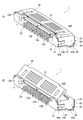
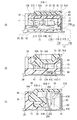
図1は、本発明の実施形態に係る平型導体用電気コネクタ1(以下「コネクタ1」という)の斜視図であり、(A)は可動部材30が閉位置にある状態、(B)は可動部材30が開位置にある状態を示している。また、図2は、図1のコネクタ1を分解した状態を平型導体Cとともに示した斜視図である。この図2では、端子20については、端子配列範囲の両端に位置する端子20のみが示されており、その他の端子20の図示は省略されている。図3は、平型導体Cの挿入前におけるコネクタ1の端子配列方向に対して直角な面での断面図であり、(A)は、端子20の位置での断面、(B)は可動部材30の係止部36の位置での断面、(C)はシェル40の係合部41Bおよび可動部材30の対応係合部35の位置での断面を示している。   FIG. 1 is a perspective view of an electrical connector 1 for flat conductors (hereinafter referred to as “connector 1”) according to an embodiment of the present invention, in which (A) shows a state where a movable member 30 is in a closed position, and (B) shows The state which the movable member 30 exists in an open position is shown. 2 is a perspective view showing a state in which the connector 1 of FIG. In FIG. 2, only the terminals 20 positioned at both ends of the terminal arrangement range are shown for the terminals 20, and the other terminals 20 are not shown. 3 is a cross-sectional view taken along a plane perpendicular to the terminal arrangement direction of the connector 1 before insertion of the flat conductor C, (A) is a cross-section at the position of the terminal 20, and (B) is a movable member. 30 shows a cross section at the position of the locking portion 36, and FIG. 9C shows a cross section at the position of the engaging portion 41B of the shell 40 and the corresponding engaging portion 35 of the movable member 30.

コネクタ1は、回路基板(図示せず)の実装面上に配され、平型導体Cが接続されることにより、上記回路基板と平型導体Cとを電気的に導通させる。ここで、「回路基板」とは、コネクタの端子に接続される回路部が形成された板状の実装部材を意味し、剛性が高い板状の部材だけでなく、剛性が低い柔軟なシート状の部材も含まれる。   The connector 1 is disposed on a mounting surface of a circuit board (not shown), and electrically connects the circuit board and the flat conductor C by connecting the flat conductor C. Here, the “circuit board” means a plate-like mounting member on which a circuit portion connected to the connector terminal is formed, and not only a plate member having high rigidity but also a flexible sheet shape having low rigidity. These members are also included.

また、本実施形態において、「端子配列範囲」とは、複数の端子が所定間隔で連続的に配列された範囲をいう。本実施形態に係るコネクタ1では、図1,2によく見られるように、全ての端子が等間隔に配列されており、一つの端子配列範囲が形成されている。   In the present embodiment, the “terminal arrangement range” refers to a range in which a plurality of terminals are continuously arranged at predetermined intervals. In the connector 1 according to the present embodiment, as often seen in FIGS. 1 and 2, all terminals are arranged at equal intervals to form one terminal arrangement range.

図2に見られるように、平型導体Cは、前後方向に延びる帯状をなし、前後方向に延びる複数の回路部(図示せず)が幅方向(前後方向に対して直角な方向)に配列され形成されている。該回路部は、平型導体Cの絶縁層内で埋設されて前後方向に延びており、平型導体Cの前端位置まで達している。また、上記回路部は、その前端側部分だけが平型導体Cの下面に露呈しており、後述するコネクタ1の端子20と接触可能となっている。また、平型導体Cは、上記前端側部分の両側縁に切欠部C1が形成されており、該切欠部C1の前方に位置する耳部C2の後端縁は、後述するコネクタ1の可動部材30の係止部36と係止する被係止部C2Aとして機能する。   As shown in FIG. 2, the flat conductor C has a strip shape extending in the front-rear direction, and a plurality of circuit portions (not shown) extending in the front-rear direction are arranged in the width direction (a direction perpendicular to the front-rear direction). Is formed. The circuit portion is embedded in the insulating layer of the flat conductor C, extends in the front-rear direction, and reaches the front end position of the flat conductor C. Further, only the front end side portion of the circuit portion is exposed on the lower surface of the flat conductor C, and can be brought into contact with a terminal 20 of the connector 1 described later. Further, the flat conductor C has notches C1 formed at both side edges of the front end side portion, and the rear end edge of the ear C2 positioned in front of the notch C1 is a movable member of the connector 1 described later. It functions as a locked portion C2A that locks with the 30 locking portions 36.

コネクタ1は、略直方体外形をなす電気絶縁材製のハウジング10と、該ハウジング10の長手方向を端子配列方向として該ハウジング10に配列保持される金属製の複数の端子20と、後述する閉位置と開位置との間で切換移動(回動)可能にハウジング10に支持される電気絶縁材製の可動部材30と、ハウジング10に取り付けられる付設部材としての金具であるシェル40とを備えている。該コネクタ1は、図1にて、平型導体C(図2参照)が後方(図1にて左方)から挿入接続されるようになっている。   The connector 1 includes a housing 10 made of an electrically insulating material having a substantially rectangular parallelepiped outer shape, a plurality of metal terminals 20 arranged and held in the housing 10 with the longitudinal direction of the housing 10 as a terminal arrangement direction, and a closed position described later. A movable member 30 made of an electric insulating material supported by the housing 10 so as to be capable of switching movement (rotation) between the open position and the open position, and a shell 40 as a fitting member attached to the housing 10. . In FIG. 1, the connector 1 is configured such that a flat conductor C (see FIG. 2) is inserted and connected from the rear (left side in FIG. 1).

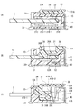
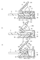
コネクタ1の詳細な構成の説明に先立って、まず、コネクタ1に対する平型導体Cの挿入および抜出の動作の概要について説明しておく。コネクタ1への平型導体Cの挿入においては、コネクタ1の可動部材30は、閉位置(図3(A)〜(C)参照)から若干開位置側へ向けて回動した位置で、平型導体Cの挿入を許容する(図4(A)〜(C)参照)。また、平型導体Cが挿入接続された後においても、コネクタ1の使用状態では、可動部材30は閉位置に維持されており、後述するように、可動部材30の係止部36と平型導体Cの被係止部C2Aとが係止可能に位置することにより、平型導体Cの後方への抜出が阻止される(図5(B)参照)。また、コネクタ1の不使用時となる平型導体Cの抜出時には、図6(A)〜(C)に示されるように、可動部材30が回動して開位置に切り換えられることにより、平型導体Cの被係止部C2Aに対する可動部材30の係止部36の係止状態が解除されて、平型導体Cの後方への抜出が許容される(図6(B)参照)。 Prior to description of the detailed configuration of the connector 1, first, an outline of operations of inserting and extracting the flat conductor C from the connector 1 will be described. At the time of insertion of the flat conductor C into the connector 1, the movable member 30 of the connector 1 is at a position slightly rotated from the closed position (see FIGS. 3A to 3C) toward the open position side . The insertion of the flat conductor C is allowed (see FIGS. 4A to 4C) . Even after the flat conductor C is inserted and connected, the movable member 30 is maintained in the closed position when the connector 1 is in use, and the locking portion 36 of the movable member 30 and the flat shape are maintained as described later. Since the locked portion C2A of the conductor C is positioned so as to be locked, the flat conductor C is prevented from being pulled out rearward (see FIG. 5B). Further, when the flat conductor C is pulled out when the connector 1 is not used, as shown in FIGS. 6A to 6C, the movable member 30 is rotated and switched to the open position. The locking state of the locking portion 36 of the movable member 30 with respect to the locked portion C2A of the flat conductor C is released, and the flat conductor C is allowed to be pulled out rearward (see FIG. 6B). .

コネクタ1の構成の説明に戻る。ハウジング10は、図1,2に見られるように、回路基板(図示せず)の実装面に対して平行な一方向を長手方向として延びており、平型導体Cを受け入れるための受入部11が、後方へ向けて開放された空間として形成されている。該ハウジング10は、上記実装面に対向して平行に延びる底壁12と、該底壁12に対向して上記長手方向、すなわち端子配列方向で端子配列範囲にわたって延びる上壁13と、端子配列方向での底壁12の両端位置で上方に起立する側壁14と、端子配列方向での端子配列範囲を含む範囲にわたって延び底壁12と上壁13の前端同士を連結する前壁15と、端子配列方向での両端寄り位置で底壁12の後端から起立し該端子配列方向で側壁14と前壁15の後端同士を連結する後壁16とを有している。   Returning to the description of the configuration of the connector 1. As shown in FIGS. 1 and 2, the housing 10 extends in a direction parallel to the mounting surface of a circuit board (not shown) as a longitudinal direction, and receives a flat conductor C 11. However, it is formed as a space opened rearward. The housing 10 includes a bottom wall 12 that extends parallel to the mounting surface, an upper wall 13 that extends across the terminal arrangement range in the longitudinal direction, that is, the terminal arrangement direction, opposite the bottom wall 12, and a terminal arrangement direction. A side wall 14 that rises upward at both end positions of the bottom wall 12, a front wall 15 that extends over a range including a terminal arrangement range in the terminal arrangement direction, and connects the front ends of the bottom wall 12 and the upper wall 13, and a terminal arrangement It has a rear wall 16 that rises from the rear end of the bottom wall 12 at a position near both ends in the direction and connects the rear end of the side wall 14 and the front wall 15 in the terminal arrangement direction.

既述した受入部11は、図1,2に見られるように、底壁12、上壁13および二つの後壁16で囲まれて後方に開口する開口部を有し、前後方向で該開口部から前壁15の後面にまでわたる空間で、平型導体C(図2参照)の前部を受け入れるようになっている(図5(A),(B)をも参照)。   As described in FIGS. 1 and 2, the receiving portion 11 described above has an opening that is surrounded by the bottom wall 12, the upper wall 13, and the two rear walls 16 and opens rearward. In the space extending from this part to the rear surface of the front wall 15, the front part of the flat conductor C (see FIG. 2) is received (see also FIGS. 5A and 5B).

また、ハウジング10には、図1,2に見られるように、複数の端子20をそれぞれ収容して保持するための端子収容部17が端子配列方向で配列形成されている。該端子収容部17は、図3(A)に見られるように、端子配列方向に対して直角に拡がるスリット状をなし、後述する端子20の下腕部21、上腕部22および連結部23を収容する収容溝部17Aと、該端子20の被保持部24を圧入保持する端子保持孔部17Bとを有している。上記収容溝部17Aは、底壁12の上面から没入して前後方向に延びる下溝部17A−1、上壁13の下面から没入して前後方向に延びる上溝部17A−2と、前壁15の後面から没入して上下方向に延びる前溝部17A−3とが互いに連通して、全体として、後方へ向けて開口した略横U字状をなしている。また、端子保持孔部17Bは下溝部17A−1から前方へ延び前壁15の下部を貫通して形成されている。   As shown in FIGS. 1 and 2, terminal housing portions 17 for housing and holding a plurality of terminals 20 are arranged in the housing 10 in the terminal array direction. As shown in FIG. 3A, the terminal accommodating portion 17 has a slit shape that expands at right angles to the terminal arrangement direction, and includes a lower arm portion 21, an upper arm portion 22, and a connecting portion 23 described later. A housing groove 17A for housing and a terminal holding hole 17B for press-fitting and holding the held portion 24 of the terminal 20 are provided. The housing groove portion 17A includes a lower groove portion 17A-1 that extends from the upper surface of the bottom wall 12 and extends in the front-rear direction, an upper groove portion 17A-2 that extends from the lower surface of the upper wall 13 and extends in the front-rear direction, and the rear surface of the front wall 15 The front groove portion 17A-3 that immerses from the top and extends in the up-down direction communicates with each other to form a substantially horizontal U shape that opens rearward as a whole. The terminal holding hole portion 17B extends forward from the lower groove portion 17A-1 and penetrates the lower portion of the front wall 15.

底壁12は、端子配列方向での端子配列範囲の外側位置で、図3(B)に見られるように、底壁12の前端の下半部が切り欠かれて段部が形成されており、該段部に、シェル40の下側被保持部41Cを圧入保持するための下側シェル保持孔部12Aが、前方へ向けて開口する孔部として形成されている。   The bottom wall 12 is located outside the terminal arrangement range in the terminal arrangement direction, and as shown in FIG. 3B, the lower half of the front end of the bottom wall 12 is cut out to form a stepped portion. The lower shell holding hole portion 12A for press-fitting and holding the lower held portion 41C of the shell 40 is formed in the step portion as a hole portion that opens forward.

上壁13は、図2によく見られるように、端子配列方向での全域にわたって該上壁13の後端縁から上方へ起立するフランジ部13Aが形成されており、該フランジ部13Aには、端子配列方向での端子配列範囲の両方の外側位置および端子配列範囲の中央位置の合計三箇所に、シェル40の上側被保持部42Aを圧入保持するための上側シェル保持孔部13Bがフランジ部13Aを前後方向に貫通して形成されている。また、該上壁13の上面には、端子配列方向での各上側シェル保持孔部13Bと同位置で前後方向に延びて該上側シェル保持孔部13Bに連通する案内溝部13Cが没入形成されている。該案内溝部13Cは、ハウジング10へのシェル40の取付けの際に、上側被保持部42Aを上側シェル保持孔部13Bへ向けて案内するようになっている。   As is often seen in FIG. 2, the upper wall 13 is formed with a flange portion 13A that rises upward from the rear edge of the upper wall 13 over the entire region in the terminal arrangement direction. Upper shell holding holes 13B for press-fitting and holding the upper held portions 42A of the shell 40 are provided at three locations, ie, the outer positions of both the terminal arrangement ranges in the terminal arrangement range and the center positions of the terminal arrangement ranges. Is formed so as to penetrate in the front-rear direction. Further, a guide groove portion 13C extending in the front-rear direction at the same position as each upper shell holding hole portion 13B in the terminal arrangement direction and communicating with the upper shell holding hole portion 13B is immersed in the upper surface of the upper wall 13. Yes. The guide groove portion 13C guides the upper held portion 42A toward the upper shell holding hole portion 13B when the shell 40 is attached to the housing 10.

側壁14は、図1,2に見られるように、後述するシェル40の側方被保持部44Aを圧入保持するための側方シェル保持突部14Aが、側壁14の外側面(端子配列方向に対して直角な面)の後端寄り位置で端子配列方向外方へ向けて突出して形成されている。また、側壁14は、図2に見られるように、前後方向での側方シェル保持突部14Aと同位置で上方そして端子配列方向内方へ向けて開口する外側支持凹部14Bが形成されている。該外側支持凹部14Bは、可動部材30の後述の回動軸部33を収容し回動可能に支持する。   As shown in FIGS. 1 and 2, the side wall 14 has a side shell holding projection 14 </ b> A for press-fitting and holding a side holding portion 44 </ b> A of the shell 40 described later. It is formed so as to protrude outward in the terminal arrangement direction at a position near the rear end of the surface perpendicular to the surface. As shown in FIG. 2, the side wall 14 is formed with an outer support recess 14B that opens upward and inward in the terminal arrangement direction at the same position as the side shell holding projection 14A in the front-rear direction. . The outer support concave portion 14B accommodates a rotation shaft portion 33 (to be described later) of the movable member 30 and rotatably supports it.

図2に見られるように、側壁14と前壁15との間には間隙18が形成されており、ハウジング10へシェル40を前方から取り付ける際に、該シェル40の後述の弾性片41Aのハウジング10内への進入を、上記間隙18によって許容している。また、図3(C)に見られるように、後壁16は、可動部材30の後述の回動被支持部34を回動可能に支持する内側支持凹部16Aが、後壁16の上部の前面に没入形成されている。   As shown in FIG. 2, a gap 18 is formed between the side wall 14 and the front wall 15, and when the shell 40 is attached to the housing 10 from the front, a housing of an elastic piece 41 </ b> A (described later) of the shell 40. 10 is allowed to enter 10. As shown in FIG. 3C, the rear wall 16 has an inner support recessed portion 16 </ b> A that rotatably supports a later-described rotation supported portion 34 of the movable member 30. Immersive is formed.

端子20は、図2によく見られるように、金属板部材の平坦な板面を維持して打ち抜いて作られており、ハウジング10の端子収容部17にそれぞれ収容されることにより、全ての端子20の板面同士が平行をなすようにしてハウジング10に等間隔で配列保持されている。   As is often seen in FIG. 2, the terminals 20 are made by punching while maintaining a flat plate surface of the metal plate member, and all the terminals are accommodated in the terminal accommodating portions 17 of the housing 10. The 20 plate surfaces are arranged and held at equal intervals in the housing 10 so as to be parallel to each other.

図3(A)に見られるように、端子20は、ハウジング10の端子収容部17の下溝部17A−1内で前後方向に延びる下腕部21と、上溝部17A−2内で前後方向に延びる上腕部22と、前溝部17A−3内で上下方向に延び下腕部21と上腕部22の前端同士を連結する連結部23と、下腕部21から前端から前方へ突出する被保持部24と、下腕部21の後端から下方そして後方へ延出する接続部25とを有している。   3A, the terminal 20 includes a lower arm portion 21 extending in the front-rear direction within the lower groove portion 17A-1 of the terminal accommodating portion 17 of the housing 10 and a front-rear direction within the upper groove portion 17A-2. An upper arm portion 22 that extends, a connecting portion 23 that extends in the vertical direction in the front groove portion 17A-3 and connects the lower arm portion 21 and the front ends of the upper arm portion 22, and a held portion that protrudes forward from the front end from the lower arm portion 21 24 and a connecting portion 25 extending downward and rearward from the rear end of the lower arm portion 21.

下腕部21は、その下半部が下溝部17A−1の溝底に沿って前後方向で該下溝部17A−1のほぼ全域にわたって直状に延びる基腕部21Aと、該基腕部21Aより上方で下腕部21の前端から後方へ向けて延びる可撓な前方弾性腕部21Bと、該基腕部21Aより上方で下腕部21の後端から前方へ向けて延びる可撓な後方弾性腕部21Cとを有している。   The lower arm portion 21 includes a base arm portion 21A, the lower half portion of which extends in a front-rear direction along the groove bottom of the lower groove portion 17A-1 over almost the entire area of the lower groove portion 17A-1, and the base arm portion 21A. A flexible front elastic arm portion 21B extending upward from the front end of the lower arm portion 21 above and a flexible rear portion extending upward from the rear end of the lower arm portion 21 above the base arm portion 21A. And an elastic arm portion 21C.

後方へ向けて延びる前方弾性腕部21Bは、前後方向での基腕部21Aの略中央位置まで延びており、上下方向で弾性変位可能となっている。該前方弾性腕部21Bは、その後端(自由端)に上方へ向けて突出する前方接触部21B−1が形成されている。図3(A)に見られるように、前方弾性腕部21Bは、後方へ向かうにつれて上方へ傾斜するように延びており、該前方弾性腕部21Bの自由状態において前方接触部21B−1が下溝部17A−1から突出して受入部11内に位置している。   The front elastic arm portion 21B extending rearward extends to a substantially center position of the base arm portion 21A in the front-rear direction, and can be elastically displaced in the vertical direction. The front elastic arm portion 21B is formed with a front contact portion 21B-1 protruding upward at the rear end (free end). As shown in FIG. 3A, the front elastic arm portion 21B extends so as to incline upward toward the rear, and the front contact portion 21B-1 is lowered in the free state of the front elastic arm portion 21B. It protrudes from the groove portion 17A-1 and is located in the receiving portion 11.

前方へ向けて延びる後方弾性腕部21Cは、前後方向での基腕部21Aの略中央位置まで、換言すると前方弾性腕部21Bの後端の近傍まで延びており、上下方向で弾性変位可能となっている。図3(A)に見られるように、該後方弾性腕部21Cは、前端側部分が前方へ向かうにつれて上方へ傾斜するように延びており、その前端(自由端)に後方接触部21C−1が形成されている。該後方接触部21C−1は、後方弾性腕部21Cの自由状態において下溝部17A−1から突出しており、受入部11内で前方接触部21B−1とほぼ同じ高さに位置している。   The rear elastic arm portion 21C extending toward the front extends to substantially the center position of the base arm portion 21A in the front-rear direction, in other words, near the rear end of the front elastic arm portion 21B, and can be elastically displaced in the vertical direction. It has become. As shown in FIG. 3A, the rear elastic arm portion 21C extends so that the front end side portion is inclined upward as it goes forward, and the rear contact portion 21C-1 at the front end (free end). Is formed. The rear contact portion 21C-1 protrudes from the lower groove portion 17A-1 in the free state of the rear elastic arm portion 21C, and is positioned at substantially the same height as the front contact portion 21B-1 in the receiving portion 11.

上腕部22は、図3(A)によく見られるように、前後方向で前方接触部21B−1と後方接触部21C−1の両方を含む範囲にわたる部分が、平型導体Cを上方から支持し前方接触部21B−1および後方接触部21C−1へ向けて下方へ押圧するための押圧部22Aとして形成されている(図5(A)参照)。該押圧部22Aは、上腕部22の他部よりも上下方向寸法が大きく形成されており、該押圧部22Aの下部が上溝部17A−2から下方へはみ出して受入部11内に位置している。該押圧部22Aの下縁と両接触部21B−1,21C−1の上端との上下方向での間隔は、平型導体Cの厚み寸法よりも小さくなっている。したがって、後述するように、平型導体Cが受入部11に挿入されると、押圧部22Aが平型導体Cを下方へ押圧することにより両弾性腕部21B,22Cが下方に弾性変位して、平型導体Cの下面の回路部と両接触部21B−1,21C−1とが接圧をもって接触するようになっている。   As is often seen in FIG. 3 (A), the upper arm portion 22 supports a flat conductor C from above in a portion including both the front contact portion 21B-1 and the rear contact portion 21C-1 in the front-rear direction. It is formed as a pressing portion 22A for pressing downward toward the front contact portion 21B-1 and the rear contact portion 21C-1 (see FIG. 5A). The pressing part 22A is formed to have a larger vertical dimension than the other part of the upper arm part 22, and the lower part of the pressing part 22A protrudes downward from the upper groove part 17A-2 and is positioned in the receiving part 11. . The distance in the vertical direction between the lower edge of the pressing portion 22A and the upper ends of the contact portions 21B-1 and 21C-1 is smaller than the thickness dimension of the flat conductor C. Therefore, as will be described later, when the flat conductor C is inserted into the receiving portion 11, the pressing portion 22A presses the flat conductor C downward, whereby both elastic arm portions 21B and 22C are elastically displaced downward. The circuit portion on the lower surface of the flat conductor C and the contact portions 21B-1 and 21C-1 are brought into contact with each other with contact pressure.

被保持部24は、上縁から上方へ向けて突出する圧入突部24Aが形成されており、該圧入突部24Aが前壁15の端子保持孔部17Bに圧入されて該端子保持孔部17Bの上側内壁面に喰い込むようになっている。また、接続部25は、下腕部21の後端から下方そして後方へ延びハウジング外に位置している。接続部25は、その下縁がハウジング10の底壁12の下面よりも若干下方に位置しており、回路基板(図示せず)の対応回路部と半田接続されるようになっている。   The held portion 24 is formed with a press-fit protrusion 24A that protrudes upward from the upper edge, and the press-fit protrusion 24A is press-fitted into the terminal holding hole 17B of the front wall 15 so that the terminal holding hole 17B. It is designed to bite into the upper inner wall surface. The connecting portion 25 extends downward and rearward from the rear end of the lower arm portion 21 and is located outside the housing. The connecting portion 25 has a lower edge located slightly below the lower surface of the bottom wall 12 of the housing 10 and is connected to a corresponding circuit portion of a circuit board (not shown) by soldering.

このような構成の端子20は、ハウジング10の端子収容部17内へ後方から圧入されて該ハウジング10に取り付けられる。端子20の取付けの際には、被保持部24が端子保持孔部17B内に圧入されて、被保持部24の圧入突部24Aが端子保持孔部17Bの上側内壁面に喰い込むとともに、下腕部21の下縁が下溝部17A−1の溝底(下側内壁面)にそして上腕部22の押圧部22Aの上縁が上溝部17A−2の溝底(上側内壁面)に接圧をもって当接することにより、端子20が端子収容部17内で保持される。   The terminal 20 having such a configuration is press-fitted into the terminal accommodating portion 17 of the housing 10 from the rear and attached to the housing 10. When the terminal 20 is attached, the held portion 24 is press-fitted into the terminal holding hole portion 17B, and the press-fitting protrusion 24A of the held portion 24 bites into the upper inner wall surface of the terminal holding hole portion 17B, and The lower edge of the arm portion 21 is in contact with the groove bottom (lower inner wall surface) of the lower groove portion 17A-1, and the upper edge of the pressing portion 22A of the upper arm portion 22 is in contact with the groove bottom (upper inner wall surface) of the upper groove portion 17A-2. The terminal 20 is held in the terminal accommodating portion 17.

可動部材30は、図2に見られるように、端子配列方向を長手方向として延びる板状をなす操作板部31と、端子配列方向での操作板部31の両端に位置し端子配列方向に対して直角な板面をもつ端板部32と、該端板部32の外側面から端子配列方向外方へ突出する回動軸部33と、該端板部32よりも端子配列方向で内側に位置する回動被支持部34、対応係合部35(図3(C)参照)および係止部36とを有している。   As shown in FIG. 2, the movable member 30 is located at both ends of the operation plate portion 31 that has a plate shape extending in the terminal arrangement direction as a longitudinal direction, and the operation plate portion 31 in the terminal arrangement direction, and is located in the terminal arrangement direction. An end plate portion 32 having a right-angled plate surface, a rotating shaft portion 33 protruding outward from the outer surface of the end plate portion 32 in the terminal arrangement direction, and inward in the terminal arrangement direction from the end plate portion 32. It has the rotation supported part 34, the corresponding engagement part 35 (refer FIG.3 (C)), and the latching | locking part 36 which are located.

操作板部31は、閉位置と開位置との間での可動部材30の回動操作を受ける。開位置にある可動部材30を閉位置へ移動させるとき、操作板部31は、該操作板部31の上面で閉位置へ向けた押圧操作力を受ける。また、閉位置における操作板部31の前端部(図3(A)〜(C)での右端部)は、閉位置にある可動部材を開位置へ回動させる際の操作を受ける解除操作部31Aとして形成されている。図3(A)ないし(C)に見られるように、解除操作部31Aの下面は、前方へ向かうにつれて上方に傾斜しており、該下面とシェル40の上面との間に形成された隙間の存在により、解除操作部31Aに指を引っ掛けて可動部材30を開位置へ回動させ、後述する係止部36と平型導体Cの被係止部C2Aとの係止状態を解除できるようになっている。   The operation plate portion 31 receives a rotation operation of the movable member 30 between the closed position and the open position. When the movable member 30 in the open position is moved to the closed position, the operation plate portion 31 receives a pressing operation force toward the closed position on the upper surface of the operation plate portion 31. Further, the front end portion (the right end portion in FIGS. 3A to 3C) of the operation plate portion 31 in the closed position is a release operation portion that receives an operation when the movable member in the closed position is rotated to the open position. It is formed as 31A. As shown in FIGS. 3A to 3C, the lower surface of the release operation portion 31 </ b> A is inclined upward as it goes forward, and a gap formed between the lower surface and the upper surface of the shell 40. Due to the presence, the finger can be hooked on the release operation portion 31A to rotate the movable member 30 to the open position so that the locked state between the locking portion 36 and the locked portion C2A of the flat conductor C can be released. It has become.

回動軸部33は、図2に見られるように、閉位置にある可動部材30の後端側に設けられており、端子配列方向で外方へ突出する円筒状の突起をなしている。該回動軸部33は、ハウジング10の外側支持凹部14B内に収容されてその軸線まわりに回動可能に支持される。なお、本実施形態では、可動部材30はハウジング10によって回動可能に支持されることとしたが、これに代えて、可動部材は端子によって回動可能に支持されてもよい。   As shown in FIG. 2, the rotation shaft portion 33 is provided on the rear end side of the movable member 30 in the closed position, and forms a cylindrical protrusion that protrudes outward in the terminal arrangement direction. The rotation shaft portion 33 is accommodated in the outer support concave portion 14B of the housing 10 and is supported so as to be rotatable about its axis. In the present embodiment, the movable member 30 is rotatably supported by the housing 10, but instead, the movable member may be rotatably supported by a terminal.

回動被支持部34および対応係合部35は、端子配列方向で互いに同位置に形成されており、該端子配列方向で端板部32に隣接した位置で該端板部32の内側面に連結されている。図3(C)に見られるように、該回動被支持部34は、閉位置にある可動部材30の操作板部31の後端部(図3(C)にて左端部)に連結され、下方へ向かうにつれて後方へ徐々に突出している。該回動被支持部34の突出頂部の後縁は回動軸部33と同心で該回動軸部33の周縁と同じ曲率の円弧をなしていて、ハウジング10の内側支持凹部16Aによって回動可動に支持されており、回動軸部33とともに可動部材30の回動軸として機能する。   The rotation supported portion 34 and the corresponding engaging portion 35 are formed at the same position in the terminal arrangement direction, and are located on the inner surface of the end plate portion 32 at a position adjacent to the end plate portion 32 in the terminal arrangement direction. It is connected. As shown in FIG. 3C, the rotation supported portion 34 is connected to the rear end portion (the left end portion in FIG. 3C) of the operation plate portion 31 of the movable member 30 in the closed position. It gradually protrudes backward as it goes downward. The rear edge of the projecting top portion of the rotation supported portion 34 is concentric with the rotation shaft portion 33 and forms an arc having the same curvature as the periphery of the rotation shaft portion 33, and is rotated by the inner support recess 16 </ b> A of the housing 10. It is supported movably and functions as a rotation shaft of the movable member 30 together with the rotation shaft portion 33.

対応係合部35は、後述するように、シェル40の係合部41Bと係合して該係合部41Bから閉位置または開位置へ向けた付勢力を受けるようになっている。該対応係合部35は、図3(C)に見られるように、回動被支持部34の下部から前方へ延びてから下方そして後方へ延び、端子配列方向に対して直角な面(図3(C)の紙面に対して平行な面)での断面形状が、後方へ開口する略横U字状をなしている。該対応係合部35の上部の前面は、前方へ向かうにつれて下方へ傾斜する第一対応係合面としての上側対応係合面35Aとして形成され、下部の前面は、前方へ向かうにつれて上方へ傾斜する第二対応係合面としての下側対応係合面35Bとして形成されている。   As will be described later, the corresponding engaging portion 35 is engaged with the engaging portion 41B of the shell 40 and receives a biasing force from the engaging portion 41B toward the closed position or the open position. As shown in FIG. 3C, the corresponding engagement portion 35 extends from the lower portion of the rotation supported portion 34 to the front, then extends downward and rearward, and is a surface perpendicular to the terminal arrangement direction (see FIG. 3C). 3 (C) is a substantially horizontal U-shape that opens rearward. The upper front surface of the corresponding engagement portion 35 is formed as an upper corresponding engagement surface 35A as a first corresponding engagement surface that is inclined downward toward the front, and the lower front surface is inclined upward toward the front. The lower corresponding engagement surface 35B is formed as the second corresponding engagement surface.

また、対応係合部35の前面で前方へ向けて突出する角部35Cは、上側対応係合面35Aと下側対応係合面35Bとの境界に位置する稜線(端子配列方向に延びる線)を有しており、該稜線は上側対応係合面35Aと下側対応係合面35Bとの交差線をなしている。上側対応係合面35Aおよび下側対応係合面35Bは、後述するように、シェル40の係合部41Bの下側係合面41B−1および上側係合面41B−2とそれぞれ係合するようになっている。   Further, the corner portion 35C protruding forward on the front surface of the corresponding engagement portion 35 is a ridge line (line extending in the terminal arrangement direction) located at the boundary between the upper corresponding engagement surface 35A and the lower corresponding engagement surface 35B. The ridge line forms a cross line between the upper corresponding engagement surface 35A and the lower corresponding engagement surface 35B. The upper corresponding engagement surface 35A and the lower corresponding engagement surface 35B engage with the lower engagement surface 41B-1 and the upper engagement surface 41B-2 of the engagement portion 41B of the shell 40, as will be described later. It is like that.

係止部36は、平型導体Cの被係止部C2A(図2参照)に対して平型導体Cの抜出方向(後方)に係止して、該平型導体Cの不用意な抜けを防止する(図5(B)参照)。係止部36は、図2に見られるように、回動被支持部34の内側面に連結されており、図3(B)によく見られるように、閉位置にある可動部材30の操作板部31の下面から下方へ突出して設けられている。図3(B)に見られる係止部36の前面は、上方へ向かうにつれて後方へ若干傾斜しており、平型導体Cの被係止部C2Aに対して係止可能な係止面36Aとして形成されている。また、係止部36の後面は、前方へ向かうにつれて下方へ傾斜する傾斜面をなし平型導体Cの挿入過程にて該平型導体Cを前方へ案内する案内面36Bとして形成されている。なお、係止面36Aが傾斜していることは必須ではなく、例えば、前後方向(図3(B)にて左右方向)に対して直角な平坦面で形成されていてもよい。   The locking portion 36 is locked in the pulling direction (rear) of the flat conductor C with respect to the locked portion C2A (see FIG. 2) of the flat conductor C, and the flat conductor C is careless. The disconnection is prevented (see FIG. 5B). The locking portion 36 is connected to the inner side surface of the rotation supported portion 34 as seen in FIG. 2, and the operation of the movable member 30 in the closed position as seen well in FIG. 3B. Projecting downward from the lower surface of the plate portion 31 is provided. The front surface of the locking portion 36 shown in FIG. 3B is slightly inclined backward as it goes upward, and serves as a locking surface 36A that can be locked to the locked portion C2A of the flat conductor C. Is formed. Further, the rear surface of the locking portion 36 is formed as a guide surface 36B that forms an inclined surface that is inclined downward toward the front and guides the flat conductor C forward in the process of inserting the flat conductor C. It is not essential that the locking surface 36A is inclined, and for example, it may be formed as a flat surface perpendicular to the front-rear direction (left-right direction in FIG. 3B).

シェル40は、金属板部材を板厚方向に屈曲して作られている。該シェル40は、回路基板の実装面に対面する底板部41と、該底板部41に対向する上板部42と、上下方向に延び底板部41および上板部42の前端同士を連結する前板部43と、上板部42の両方の側縁(前後方向に延びる縁部)で下方に向けて屈曲された側板部44と、該側板部44の下縁で端子配列方向での外方へ向けて屈曲された固定部45とを有している。後述するように、底板部41、上板部42および前板部43は、端子配列方向での端子配列範囲を含む範囲で、ハウジング10の底壁12、上壁13および前壁15をそれぞれ下方、上方そして前方から覆って上記端子配列範囲を遮蔽するための覆板部として機能する。   The shell 40 is made by bending a metal plate member in the plate thickness direction. The shell 40 includes a bottom plate portion 41 that faces the mounting surface of the circuit board, an upper plate portion 42 that faces the bottom plate portion 41, and extends in the vertical direction before the front ends of the bottom plate portion 41 and the upper plate portion 42 are connected to each other. A side plate portion 44 bent downward at both side edges (edge portions extending in the front-rear direction) of the plate portion 43 and the upper plate portion 42, and outward in the terminal arrangement direction at the lower edge of the side plate portion 44 And a fixing portion 45 bent toward the front. As will be described later, the bottom plate portion 41, the upper plate portion 42, and the front plate portion 43 are disposed below the bottom wall 12, the upper wall 13, and the front wall 15 of the housing 10 within a range including the terminal arrangement range in the terminal arrangement direction. It functions as a cover plate part for covering from above and from the front to shield the terminal arrangement range.

底板部41は、端子配列方向での端子配列範囲の外側位置に、可動部材30の対応係合部35と係合する弾性腕部としての弾性片41Aと、ハウジング10へシェル40の取付けのための下側被保持部41Cとを有している。   The bottom plate portion 41 has an elastic piece 41 </ b> A as an elastic arm portion that engages with the corresponding engagement portion 35 of the movable member 30 at an outer position of the terminal arrangement range in the terminal arrangement direction, and the shell 40 to the housing 10. Lower-side held portion 41C.

弾性片41Aは、図2によく見られるように、端子配列方向で側板部44に寄った位置で、底板部41の一部を上方へ切り起こして形成された帯板状をなしており、その板厚方向に弾性変位可能となっている。図3(C)に見られるように、弾性片41Aは、後方へ向けて延びた帯状片を上方へ向けて屈曲して形成されており、可動部材30の操作板部31の下面近傍まで延びている。また、該弾性片41Aは、後方へ向けて若干傾斜しており、該弾性片41Aの上端側部分に可動部材30の対応係合部35に係合するための係合部41Bが形成されている。該係合部41Bは、該係合部41Bの上下方向での中間位置で前方側へ屈曲されており、後方へ向けて突出した屈曲部41B−3が形成されている。   As is often seen in FIG. 2, the elastic piece 41 </ b> A has a strip shape formed by cutting and raising a part of the bottom plate portion 41 at a position close to the side plate portion 44 in the terminal arrangement direction. Elastic displacement is possible in the thickness direction. As shown in FIG. 3C, the elastic piece 41 </ b> A is formed by bending a strip-like piece extending rearward upward, and extends to the vicinity of the lower surface of the operation plate portion 31 of the movable member 30. ing. The elastic piece 41A is slightly inclined toward the rear, and an engaging portion 41B for engaging with the corresponding engaging portion 35 of the movable member 30 is formed on the upper end side portion of the elastic piece 41A. Yes. The engagement portion 41B is bent forward at an intermediate position in the vertical direction of the engagement portion 41B, and a bent portion 41B-3 protruding rearward is formed.

本実施形態では、屈曲部41B−3の下方に位置する部分の後面は、可動部材30の上側対応係合面35A(第一対応係合面)に係合する第一係合面としての下側係合面41B−1として形成されている(図3(C)参照)。また、屈曲部41B−3の上方に位置する部分の後面は、可動部材30の下側対応係合面35B(第二対応係合面)に係合する第二係合面としての上側係合面41B−2として形成されている(図6(C)をも参照)。下側係合面41B−1は上側対応係合面35Aに係合することにより可動部材30を閉位置へ向けて付勢し(図3(C)参照)、上側係合面41B−2は下側対応係合面35Bに係合することにより可動部材30を開位置へ向けて付勢する(図6(C)参照)。   In the present embodiment, the rear surface of the portion located below the bent portion 41B-3 is a lower surface as a first engagement surface that engages with the upper corresponding engagement surface 35A (first corresponding engagement surface) of the movable member 30. It is formed as a side engagement surface 41B-1 (see FIG. 3C). Further, the rear surface of the portion located above the bent portion 41B-3 is an upper engagement as a second engagement surface that engages with the lower corresponding engagement surface 35B (second corresponding engagement surface) of the movable member 30. It is formed as a surface 41B-2 (see also FIG. 6C). The lower engagement surface 41B-1 urges the movable member 30 toward the closed position by engaging with the upper corresponding engagement surface 35A (see FIG. 3C), and the upper engagement surface 41B-2 The movable member 30 is biased toward the open position by engaging with the lower corresponding engagement surface 35B (see FIG. 6C).

下側被保持部41Cは、図2に見られるように、弾性片41Aよりも端子配列方向で内側に位置しており、底板部41の前端寄り位置で底板部41の一部を上方へ切り起こして形成された帯板状をなしている。該下側被保持部41Cは、後方へ向けて延びた帯状片を上方そして後方へ向けてクランク状に屈曲して形成されており、後方へ向けて延びる自由端側部分に、下方へ向けて突出する圧入突部41C−1がプレス加工により形成されている。図3(B)に見られるように、下側被保持部41Cはハウジング10の下側シェル保持孔部12Aへ前方から圧入されて該下側シェル保持孔部12Aで保持される。   As shown in FIG. 2, the lower held portion 41 </ b> C is located on the inner side in the terminal arrangement direction with respect to the elastic piece 41 </ b> A and cuts a part of the bottom plate portion 41 upward at a position near the front end of the bottom plate portion 41. It is shaped like a strip that is raised. The lower held portion 41C is formed by bending a belt-like piece extending rearward in a crank shape upward and rearward, and downward toward a free end side portion extending rearward. A protruding press-fit protrusion 41C-1 is formed by pressing. As shown in FIG. 3B, the lower held portion 41C is press-fitted from the front into the lower shell holding hole 12A of the housing 10 and is held by the lower shell holding hole 12A.

上板部42は、図2に見られるように、端子配列方向でのハウジング10の各上側シェル保持孔部13Bに対応する位置に、該上側シェル保持孔部13Bで圧入保持される上側被保持部42Aが、上板部42の後端側部分が切り起こされて形成されている。該上側被保持部42Aは、後方へ向けて延びた帯状片を下方そして後方へ向けてクランク状に屈曲して形成されており、後方へ向けて延びる自由端側部分に、下方へ向けて突出する圧入突部がプレス加工により形成されている。該上側被保持部42Aはハウジング10の上側シェル保持孔部13Bへ前方から圧入されて保持される。   As shown in FIG. 2, the upper plate portion 42 is press-held by the upper shell holding hole 13 </ b> B at a position corresponding to each upper shell holding hole 13 </ b> B of the housing 10 in the terminal arrangement direction. The portion 42A is formed by cutting and raising the rear end portion of the upper plate portion 42. The upper held portion 42A is formed by bending a belt-like piece extending rearward in a crank shape downward and rearward, and projects downward in a free end portion extending rearward. The press-fitting protrusion to be formed is formed by press working. The upper held portion 42A is pressed into the upper shell holding hole 13B of the housing 10 from the front and is held.

側板部44は、図2に見られるように、ハウジング10へシェル40の取付けのための側方被保持部44Aが、側板部44の後半部で後方へ向けて開口した凹部として形成されている。側方被保持部44Aは、その下縁に上方へ向けて突出する圧入突部44A−1が形成されている。側方被保持部44Aは、図1(A),(B)に見られるように、ハウジング10の側方シェル保持突部14Aを後方から受け入れて、圧入突部44A−1が側方シェル保持突部14Aの下面に喰い込むことにより圧入保持される。   As shown in FIG. 2, the side plate portion 44 is formed as a concave portion in which a side supported portion 44 </ b> A for attaching the shell 40 to the housing 10 is opened rearward in the rear half portion of the side plate portion 44. . The side held portion 44A is formed with a press-fit protrusion 44A-1 protruding upward at the lower edge thereof. As shown in FIGS. 1A and 1B, the side held portion 44A receives the side shell holding projection 14A of the housing 10 from the rear, and the press-fit projection 44A-1 holds the side shell. It is press-fitted and held by biting into the lower surface of the protrusion 14A.

また、側板部44は、その上縁で端子配列方向内方へ向けて屈曲され上下方向に対して直角な板面をもつ板部が、ハウジング10からの可動部材30の不用意な抜けを防止するための規制部44Bとして形成されている。規制部44Bは、シェル40がハウジング10に取り付けられた状態で、可動部材30の回動軸部33を収容する外側支持凹部14Bの開口部を上方から閉塞するように位置して、該回動軸部33の上方への移動を規制することにより、ハウジング10からの可動部材30の不用意な抜けを防止するようになっている。   Further, the side plate portion 44 is bent inwardly in the terminal arrangement direction at the upper edge thereof, and the plate portion having a plate surface perpendicular to the vertical direction prevents the movable member 30 from being inadvertently detached from the housing 10. It is formed as a restricting portion 44B for this purpose. The restricting portion 44B is positioned so as to close the opening of the outer support concave portion 14B that accommodates the rotating shaft portion 33 of the movable member 30 from above with the shell 40 being attached to the housing 10, and is thus rotated. By restricting the upward movement of the shaft portion 33, the movable member 30 is prevented from being unintentionally detached from the housing 10.

固定部45は、底板部41とほぼ同じ高さに位置しており、回路基板(図示せず)の対応部に半田付けされて固定されるようになっている。固定部45は板厚方向に貫通する固定孔部45Aが形成されており、固定孔部45A内に溶融した半田が流れ込むことにより、上記対応部に固定部45がより確実に固定されるようになっている。   The fixing portion 45 is located at substantially the same height as the bottom plate portion 41, and is fixed by soldering to a corresponding portion of a circuit board (not shown). The fixing portion 45 is formed with a fixing hole portion 45A penetrating in the plate thickness direction so that the molten portion flows into the fixing hole portion 45A, so that the fixing portion 45 is more securely fixed to the corresponding portion. It has become.

このような構成のコネクタ1は、以下の要領で組み立てられる。まず、ハウジング10の端子収容部17へ端子20を後方から圧入して取り付ける。また、ハウジング10の外側支持凹部14B内に可動部材30の回動軸部33を上方から収容させて、該可動部材30をハウジングに取り付ける。この結果、回動軸部33は外側支持凹部14Bにて回動可能に支持され、また、これと同時に、可動部材30の回動被支持部34もハウジング10の内側支持凹部16Aに回動可能に支持される(図3(C)参照)。上述した端子20の取付工程および可動部材30の取付工程は、どちらが先に行われてもよく、また、同時に行われてもよい。   The connector 1 having such a configuration is assembled in the following manner. First, the terminal 20 is press-fitted and attached to the terminal accommodating portion 17 of the housing 10 from the rear. Further, the rotating shaft portion 33 of the movable member 30 is accommodated from above in the outer support concave portion 14B of the housing 10, and the movable member 30 is attached to the housing. As a result, the rotation shaft portion 33 is rotatably supported by the outer support concave portion 14B, and at the same time, the rotation supported portion 34 of the movable member 30 can also be rotated to the inner support concave portion 16A of the housing 10. (See FIG. 3C). Either the terminal 20 mounting step or the movable member 30 mounting step described above may be performed first, or may be performed simultaneously.

次に、シェル40の下側被保持部41C、上側被保持部42Aおよび側方被保持部44Aを、ハウジング10の下側シェル保持孔部12A、上側シェル保持孔部13Bおよび側方シェル保持突部14Aにそれぞれ前方から圧入することにより、ハウジング10にシェル40を取り付ける。シェル40がハウジング10に取り付けられる結果、該シェル40の規制部44Bがハウジング10の外側支持凹部14Bの開口部を上方から閉塞するように位置することにより、ハウジング10からの可動部材30の不用意な抜けが防止される。   Next, the lower held portion 41C, the upper held portion 42A, and the side held portion 44A of the shell 40 are replaced with the lower shell holding hole portion 12A, the upper shell holding hole portion 13B, and the side shell holding projection of the housing 10. The shell 40 is attached to the housing 10 by press-fitting each part 14A from the front. As a result of the shell 40 being attached to the housing 10, the restricting portion 44 </ b> B of the shell 40 is positioned so as to close the opening of the outer support recess 14 </ b> B of the housing 10 from above, so that the movable member 30 from the housing 10 is not prepared. Slipping out is prevented.

また、シェル40がハウジング10に取り付けられた状態において、シェル40の底板部41、上板部42および前板部43が、端子配列方向での端子配列範囲を含む範囲で、ハウジング10の底壁12、上壁13および前壁15をそれぞれ下方、上方そして前方から覆うことにより良好なシールド効果が得られる。   Further, when the shell 40 is attached to the housing 10, the bottom wall of the housing 10 is within a range in which the bottom plate portion 41, the upper plate portion 42 and the front plate portion 43 of the shell 40 include the terminal arrangement range in the terminal arrangement direction. 12. A good shielding effect can be obtained by covering the upper wall 13 and the front wall 15 from below, above and from the front.

次に、コネクタ1と平型導体Cとの接続動作を図3〜5に基づいて説明する。まず、コネクタ1の端子20の接続部25を回路基板の対応回路部に半田接続するとともに、シェル40の固定部45を回路基板の対応部に半田接続して固定する。   Next, the connection operation between the connector 1 and the flat conductor C will be described with reference to FIGS. First, the connection part 25 of the terminal 20 of the connector 1 is soldered to the corresponding circuit part of the circuit board, and the fixing part 45 of the shell 40 is soldered and fixed to the corresponding part of the circuit board.

次に、可動部材30を閉位置にもたらすとともに(図3(A)〜(C)参照)、コネクタ1の後方に平型導体Cを回路基板(図示せず)の実装面に沿って前後方向に延びるように位置させる。次に、平型導体Cを前方へ向けてコネクタ1の受入部11に挿入する。受入部11への平型導体Cの挿入過程において、該平型導体Cは、端子20の下腕部21と上腕部22との間に進入し、上腕部22の押圧部22Aによって上方から押圧されることにより、まず、図4(A)に見られるように、下腕部21の後方弾性腕部21Cの後方接触部21C−1に、上方から接圧をもって接触し、後方弾性腕部21Cを下方へ向けて弾性変位させる。平型導体Cがさらに挿入されると、該平型導体Cは、前方弾性腕部21Bの前方接触部21B−1に上方から接圧をもって接触し、前方弾性腕部21Bを下方へ向けて弾性変位させる。   Next, the movable member 30 is brought to the closed position (see FIGS. 3A to 3C), and the flat conductor C is disposed behind the connector 1 along the mounting surface of the circuit board (not shown). It is located to extend to. Next, the flat conductor C is inserted forward into the receiving portion 11 of the connector 1. In the process of inserting the flat conductor C into the receiving portion 11, the flat conductor C enters between the lower arm portion 21 and the upper arm portion 22 of the terminal 20 and is pressed from above by the pressing portion 22 </ b> A of the upper arm portion 22. As a result, first, as shown in FIG. 4A, the rear elastic arm portion 21C comes into contact with the rear contact portion 21C-1 of the rear elastic arm portion 21C of the lower arm portion 21 with contact pressure from above. Is elastically displaced downward. When the flat conductor C is further inserted, the flat conductor C comes into contact with the front contact portion 21B-1 of the front elastic arm portion 21B with contact pressure from above, and elastically moves the front elastic arm portion 21B downward. Displace.

また、平型導体Cの両側端寄りに位置する耳部C2の前端が、可動部材30の係止部36の案内面36Bに当接して可動部材30を開位置側へ向けて回動させて、可動部材30を上記平型導体Cの挿入を許容する位置にもたらす。このとき、開位置側へ向けて回動した可動部材30は、図4(B)に見られるように、係止部36の案内面36Bが平型導体Cの耳部C2の上面と接面した時点で回動角度が最大となる。   Further, the front end of the ear portion C2 located near the both ends of the flat conductor C abuts on the guide surface 36B of the locking portion 36 of the movable member 30 to rotate the movable member 30 toward the open position. The movable member 30 is brought to a position where the insertion of the flat conductor C is allowed. At this time, in the movable member 30 rotated toward the open position, the guide surface 36B of the locking portion 36 is in contact with the upper surface of the ear portion C2 of the flat conductor C, as seen in FIG. At that time, the rotation angle becomes maximum.

一方、可動部材30は、図4(C)に見られるように、対応係合部35の角部35Cでシェル40の係合部41Bを押圧して該弾性片41Aを後方へ弾性変位させる。図4(C)に見られるように対応係合部35の角部35Cが係合部41Bの下側係合面41B−1を押圧しているのは、上述したように可動部材30の回動角度が最大となった状態である。したがって、平型導体Cの挿入過程にて、可動部材30がさらに開位置側へ向けて回動して上記角部35Cが係合部41Bの屈曲部41B−3を乗り越えることはない。つまり、係合部41Bの上側係合面41B−2が対応係合部35の下側対応係合面35Bに係合する状態、すなわち可動部材30を開位置へ向けて付勢する状態(図6(C)参照)に切り換わることはない。したがって、平型導体Cの挿入過程においては、下側係合面41B−1が可動部材30を閉位置へ向けて付勢する状態が常に維持される。   On the other hand, as shown in FIG. 4C, the movable member 30 presses the engaging portion 41B of the shell 40 with the corner portion 35C of the corresponding engaging portion 35 to elastically displace the elastic piece 41A backward. As shown in FIG. 4C, the corner portion 35C of the corresponding engaging portion 35 presses the lower engaging surface 41B-1 of the engaging portion 41B as described above. This is a state in which the moving angle is maximized. Therefore, in the process of inserting the flat conductor C, the movable member 30 does not further rotate toward the open position side, and the corner portion 35C does not get over the bent portion 41B-3 of the engaging portion 41B. That is, the state in which the upper engagement surface 41B-2 of the engagement portion 41B is engaged with the lower corresponding engagement surface 35B of the corresponding engagement portion 35, that is, the state in which the movable member 30 is biased toward the open position (see FIG. 6 (C)). Therefore, in the process of inserting the flat conductor C, the state in which the lower engagement surface 41B-1 urges the movable member 30 toward the closed position is always maintained.

平型導体Cがさらに前方へ挿入されると、図5(A)〜(C)に見られるように、該平型導体Cの前端が前壁15の後面に当接して、挿入完了位置にもたらされる。図5(A)に見られるように、平型導体Cの挿入完了状態では、前方弾性腕部21Bおよび後方弾性腕部21Cの弾性変位状態が維持されており、平型導体Cの下面の回路部と前方接触部21B−1と後方接触部21C−1とが接圧をもって接触し電気的に導通した状態が維持され、平型導体Cの接続動作が完了する。   When the flat conductor C is further inserted forward, as shown in FIGS. 5A to 5C, the front end of the flat conductor C comes into contact with the rear surface of the front wall 15 to reach the insertion completion position. Brought about. As shown in FIG. 5A, in the state where the flat conductor C is completely inserted, the elastic displacement states of the front elastic arm portion 21B and the rear elastic arm portion 21C are maintained, and the circuit on the lower surface of the flat conductor C is maintained. The front contact portion 21 </ b> B- 1 and the rear contact portion 21 </ b> C- 1 are in contact with each other with contact pressure and are electrically connected, and the connection operation of the flat conductor C is completed.

また、平型導体Cが挿入完了位置にもたらされると、図5(B)に見られるように、平型導体Cの耳部C2が係止部36の位置を通過して該係止部36よりも前方にもたらされる。したがって、可動部材30がシェル40の係合部41Bからの付勢力を受けて閉位置へ復帰することにより、係止部36は、図5(B)に見られるように、平型導体Cの切欠部C1内に上方から突入する。この結果、平型導体Cの被係止部C2Aが係止部36の係止面36Aに対して係止可能に位置するので、平型導体Cの後方への抜出が阻止される。   When the flat conductor C is brought to the insertion completion position, as shown in FIG. 5B, the ear C2 of the flat conductor C passes through the position of the locking portion 36 and the locking portion 36 is reached. Is brought forward than. Therefore, when the movable member 30 receives the urging force from the engaging portion 41B of the shell 40 and returns to the closed position, the locking portion 36 has the flat conductor C as shown in FIG. It rushes into the cutout C1 from above. As a result, the engaged portion C2A of the flat conductor C is positioned so as to be engageable with the engaging surface 36A of the engaging portion 36, so that the flat conductor C is prevented from being pulled out rearward.

可動部材30が閉位置へ戻されると、図5(C)に見られるように、係合部41Bの下側係合面41B−1が対応係合部35の上側対応係合面35Aに付勢力をもって接面して係合するので、可動部材30は下側係合面41B−1からの付勢力により常に閉位置に維持される。したがって、仮に、コネクタ1と平型導体Cとの接続状態において、平型導体Cに後方へ向けた過大な抜出力が作用することにより、可動部材30が開位置側へ向けて若干もち上がってしまっても、該可動部材30は下側係合面41B−1からの付勢力により閉位置へ押し戻されるので、平型導体Cの不用意に抜けることはない。   When the movable member 30 is returned to the closed position, the lower engaging surface 41B-1 of the engaging portion 41B is attached to the upper corresponding engaging surface 35A of the corresponding engaging portion 35 as seen in FIG. Since the contact surface engages with the force, the movable member 30 is always maintained in the closed position by the force from the lower engagement surface 41B-1. Therefore, if the connector 1 and the flat conductor C are connected to each other, an excessive pulling output directed toward the rear acts on the flat conductor C, so that the movable member 30 is slightly lifted toward the open position. Even then, the movable member 30 is pushed back to the closed position by the urging force from the lower engagement surface 41B-1, so that the flat conductor C does not come out carelessly.

次に、コネクタ1からの平型導体Cの抜出動作を図5および図6に基づいて説明する。まず、図5(A)〜(C)に見られるような平型導体Cとの接続状態にて、コネクタ1の可動部材30の解除操作部31Aに指を引っ掛けてもち上げて、上述した係合部41Bからの閉位置へ向けた付勢力に抗して、可動部材30を開位置へ向けて回動させる。このとき、係止部36は、上方へ、すなわち平型導体Cの切欠部C1から脱出する方向へ移動する。   Next, the operation of extracting the flat conductor C from the connector 1 will be described with reference to FIGS. First, in the connected state with the flat conductor C as seen in FIGS. 5A to 5C, the finger is hooked on the release operation portion 31A of the movable member 30 of the connector 1, and the above-described engagement is performed. The movable member 30 is rotated toward the open position against the urging force toward the closed position from the joint portion 41B. At this time, the locking portion 36 moves upward, that is, in a direction to escape from the cutout portion C1 of the flat conductor C.

可動部材30が開位置へ向けて回動する過程にて、可動部材30の対応係合部35の角部35Cはシェル40の弾性片41Aを前方へ向けて弾性変位させる。上記角部35Cが係合部41Bの屈曲部41B−3の位置に達するまでの間は、該係合部41Bの下側係合面41B−1が可動部材30を閉位置へ向けて付勢する。そして、さらに可動部材30を回動させて、上記角部35Cが係合部41Bの屈曲部41B−3の位置を乗り越えて、該角部35Cは係合部41Bの上側係合面41B−2の領域に達すると、弾性片41Aが弾性変位量を減ずる方向(後方)に戻るとともに、係合部41Bが上側係合面41B−2で可動部材30を開位置へ向けて付勢する。このようにして可動部材30が開位置に切り換えられると、図6(C)に見られるように、係合部41Bの上側係合面41B−2が対応係合部35の下側対応係合面35Bに付勢力をもって接面して係合する。この結果、上側係合面41B−2からの付勢力により閉位置へ向けた可動部材30の戻り移動が規制され、該可動部材30が開位置に維持される。   In the process in which the movable member 30 rotates toward the open position, the corner portion 35C of the corresponding engagement portion 35 of the movable member 30 elastically displaces the elastic piece 41A of the shell 40 toward the front. Until the corner portion 35C reaches the position of the bent portion 41B-3 of the engaging portion 41B, the lower engaging surface 41B-1 of the engaging portion 41B biases the movable member 30 toward the closed position. To do. Further, the movable member 30 is further rotated so that the corner portion 35C gets over the position of the bent portion 41B-3 of the engaging portion 41B, and the corner portion 35C becomes the upper engaging surface 41B-2 of the engaging portion 41B. The elastic piece 41A returns to the direction in which the elastic displacement amount decreases (rearward), and the engaging portion 41B biases the movable member 30 toward the open position with the upper engaging surface 41B-2. When the movable member 30 is switched to the open position in this way, the upper engaging surface 41B-2 of the engaging portion 41B is engaged with the lower corresponding engaging portion 35 as seen in FIG. The surface 35B is brought into contact with and engaged with the urging force. As a result, the return movement of the movable member 30 toward the closed position is restricted by the urging force from the upper engagement surface 41B-2, and the movable member 30 is maintained in the open position.

また、可動部材30が開位置に切り換えられると、図6(B)に見られるように、係止部36は、平型導体Cの切欠部C1から完全に脱出し、該平型導体Cの被係止部C2Aとの係止状態が解除される。また、このとき、図6(A)に見られるように、平型導体Cの下面の回路部と端子20の両接触部21B−1,21C−1との接圧をもった接触状態は維持されたままである。このように、可動部材30が開位置に維持された状態で、平型導体Cを後方へ向けて引くことにより、該平型導体Cがコネクタ1から難なく抜出され、抜出動作が完了する。   When the movable member 30 is switched to the open position, as shown in FIG. 6 (B), the locking portion 36 completely escapes from the cutout portion C1 of the flat conductor C, and the flat conductor C The locked state with the locked portion C2A is released. At this time, as shown in FIG. 6A, the contact state having the contact pressure between the circuit portion on the lower surface of the flat conductor C and the contact portions 21B-1 and 21C-1 of the terminal 20 is maintained. It has been done. In this way, by pulling the flat conductor C backward while the movable member 30 is maintained in the open position, the flat conductor C is extracted from the connector 1 without difficulty, and the extraction operation is completed. .

本実施形態では、シェル40の係合部41Bは、該係合部41Bの屈曲部41B−3が可動部材30の対応係合部35の角部35Cに対して上側にあるときには、該係合部41Bの下側係合面41B−1が該対応係合部35の上側対応係合面35Aと係合して可動部材30を閉位置へ向けて付勢し、該係合部41Bの屈曲部41B−3が対応係合部35の角部35Cに対して下側にあるときには、係合部41Bの上側係合面41B−2が該対応係合部35の下側対応係合面35Bと係合して可動部材30を開位置へ向けて付勢する。したがって、平型導体Cを抜出する際に、閉位置にあった可動部材30が一旦、開位置に切り換えられると、該可動部材30が係合部41Bからの付勢力により開位置に維持される。   In the present embodiment, the engaging portion 41B of the shell 40 is engaged when the bent portion 41B-3 of the engaging portion 41B is above the corner portion 35C of the corresponding engaging portion 35 of the movable member 30. The lower engagement surface 41B-1 of the portion 41B engages with the upper corresponding engagement surface 35A of the corresponding engagement portion 35 to urge the movable member 30 toward the closed position, and the engagement portion 41B is bent. When the portion 41B-3 is below the corner portion 35C of the corresponding engaging portion 35, the upper engaging surface 41B-2 of the engaging portion 41B is the lower corresponding engaging surface 35B of the corresponding engaging portion 35. And the movable member 30 is urged toward the open position. Therefore, when the movable member 30 in the closed position is once switched to the open position when the flat conductor C is pulled out, the movable member 30 is maintained in the open position by the urging force from the engaging portion 41B. The

したがって、従来のように作業者が可動部材を開位置に維持するために該可動部材30を押さえておく必要がなくなるので、本発明では、平型導体Cの抜出過程において、一方の手で可動部材30を開位置にもたらした後、該可動部材30から上記一方の手を放し、該一方の手で平型導体Cを把持して抜出することができる。つまり、可動部材30を開位置に移動させてから平型導体Cを抜出するという一連の作業を片手のみで簡単に行うことができる。また、本実施形態では、両手で抜出作業を行うための十分なスペースがコネクタ1の周囲に確保されていなくても、片手だけで抜出作業を行うことができる。   Therefore, since it is not necessary for the operator to hold down the movable member 30 in order to maintain the movable member in the open position as in the prior art, in the present invention, in the process of extracting the flat conductor C, one hand is used. After bringing the movable member 30 to the open position, the one hand can be released from the movable member 30, and the flat conductor C can be grasped and pulled out by the one hand. That is, a series of operations of extracting the flat conductor C after moving the movable member 30 to the open position can be easily performed with only one hand. Moreover, in this embodiment, even if sufficient space for performing the extraction operation with both hands is not secured around the connector 1, the extraction operation can be performed with only one hand.

また、本実施形態では、可動部材30を閉位置または開位置へ付勢するための係合部41Bを金具であるシェル40に形成しているので、係合部41B自体の強度を大きくすることができる。したがって、該係合部41Bが破損しにくくなり、対応係合部35ひいては可動部材30を閉位置あるは開位置へ向けて確実に付勢することができる。なお、係合部の十分な強度を確保できる場合には、該係合部をハウジングの一部で形成してもよい。この場合、例えば、係合部をハウジング10の底壁12から起立する弾性変位可能な弾性片に形成することができる。   In the present embodiment, since the engaging portion 41B for urging the movable member 30 to the closed position or the open position is formed on the shell 40 that is a metal fitting, the strength of the engaging portion 41B itself is increased. Can do. Therefore, the engaging portion 41B is less likely to be damaged, and the corresponding engaging portion 35 and thus the movable member 30 can be reliably urged toward the closed position or the open position. In addition, when sufficient intensity | strength of an engaging part can be ensured, you may form this engaging part in a part of housing. In this case, for example, the engaging portion can be formed as an elastically displaceable elastic piece standing from the bottom wall 12 of the housing 10.

本発明では、既述した実施形態に限られず、以下に述べるような種々の変形例で実施することも可能である。   The present invention is not limited to the above-described embodiments, and can be implemented in various modifications as described below.

本実施形態では、シェル40に設けられた弾性片41の係合部41Bは、それぞれ可動部材30の切換移動中のみならず切換移動後、すなわち可動部材30が閉位置あるいは開位置に達した後においても、該可動部材30を付勢するが、これに代えて、切換移動中のみ可動部材30を付勢することとしてもよい。具体的には、可動部材30の切換移動後においては弾性片41が自由状態にあり可動部材30を付勢せず、切換移動の過程にて係合部41Bが対応係合部35に押圧されて弾性変位したときのみ、該係合部41Bが可動部材30を付勢して可動部材30が閉位置あるいは開位置にもたらす。そして、このような係合部41Bによる付勢の結果、可動部材30が閉位置あるいは開位置に維持される。   In this embodiment, the engaging portions 41B of the elastic pieces 41 provided on the shell 40 are not only during the switching movement of the movable member 30, but also after the switching movement, that is, after the movable member 30 reaches the closed position or the open position. In this case, the movable member 30 is urged. Alternatively, the movable member 30 may be urged only during the switching movement. Specifically, after the moving movement of the movable member 30, the elastic piece 41 is in a free state and does not bias the movable member 30, and the engaging portion 41B is pressed by the corresponding engaging portion 35 in the process of switching movement. Only when elastically displaced, the engaging portion 41B biases the movable member 30 to bring the movable member 30 to the closed position or the open position. As a result of the biasing by the engaging portion 41B, the movable member 30 is maintained in the closed position or the open position.

本実施形態では、可動部材30の対応係合部35の上側対応係合面35Aと下側対応係合面35Bとを隔てる境界部分が角部35Cの稜線であることとしたが、これに代えて、該境界部分は、例えば、凸湾曲面や平面等であってもよい。つまり、上側対応係合面と下側対応係合面が上記端子配列方向に延びる線上に交差線をもつような位置関係にあればよい。この場合、係合部は、上記交差線よりも上側にあるときには、上側対応係合面と係合して可動部材を閉位置へ向けて付勢し、上記交差線よりも下側にあるときには、下側対応係合面と係合して可動部材を開位置へ向けて付勢する。   In this embodiment, the boundary portion separating the upper corresponding engagement surface 35A and the lower corresponding engagement surface 35B of the corresponding engagement portion 35 of the movable member 30 is the ridge line of the corner portion 35C. The boundary portion may be, for example, a convex curved surface or a flat surface. That is, it is sufficient that the upper corresponding engagement surface and the lower corresponding engagement surface have a positional relationship such that an intersection line is formed on a line extending in the terminal arrangement direction. In this case, when the engaging portion is above the intersecting line, it engages with the upper corresponding engaging surface to urge the movable member toward the closed position, and when the engaging portion is below the intersecting line. The movable member is urged toward the open position by engaging with the lower corresponding engagement surface.

本実施形態では、シェル40に設けられた弾性変位可能な係合部41Bが、可動部材30に設けられ弾性変位しない対応係合部35を付勢することとしたが、これに代えて、弾性変位可能な対応係合部を可動部材に設けるとともに、弾性変位しない係合部をシェルに設けて、該対応係合部が該係合部を付勢するようにしてもよい。この場合、対応係合部が係合部を付勢して該係合部から受ける反力により、可動部材が閉位置または開位置に維持される。また、本実施形態では、係合部および対応係合部は、いずれか一方が弾性変位可能であることとしたが、これに代えて、両方が弾性変位可能となっていてもよい。   In the present embodiment, the elastically displaceable engaging portion 41B provided on the shell 40 urges the corresponding engaging portion 35 provided on the movable member 30 and not elastically displaced. A corresponding engaging portion that can be displaced may be provided on the movable member, and an engaging portion that is not elastically displaced may be provided on the shell so that the corresponding engaging portion biases the engaging portion. In this case, the movable member is maintained in the closed position or the open position by the reaction force that the corresponding engaging portion biases the engaging portion and receives from the engaging portion. In the present embodiment, one of the engaging portion and the corresponding engaging portion is elastically displaceable. Alternatively, both may be elastically displaceable.

本実施形態では、シェル40は、底板部41、上板部42および前板部43を有し、端子20の配列範囲を下方、上方そして前方から覆って遮蔽することとしたが、ある程度のシールド効果が得られれば済むような場合には、端子配列範囲に底板部41、上板部42および前板部43の全てを設けることは必須ではない。また、特にシールド効果が要求されない場合には、端子配列範囲に対応する位置に金具を設けることなく、端子配列方向での端子配列範囲外の位置にハウジング10に金具を取り付け、該金具に係合部を形成することとしてもよい。   In the present embodiment, the shell 40 has the bottom plate portion 41, the upper plate portion 42, and the front plate portion 43, and covers and shields the arrangement range of the terminals 20 from below, from above, and from the front. When it is sufficient to obtain the effect, it is not essential to provide all of the bottom plate portion 41, the upper plate portion 42, and the front plate portion 43 in the terminal arrangement range. In addition, when the shielding effect is not particularly required, a metal fitting is attached to the housing 10 at a position outside the terminal arrangement range in the terminal arrangement direction without engaging the metal fitting at a position corresponding to the terminal arrangement range, and is engaged with the metal fitting. It is good also as forming a part.

本実施形態では、可動部材30の係止部36、対応係合部35およびシェル40の係合部41Bは、端子配列方向でのコネクタ1の両端側に設けられていることとしたが、例えば、端子配列範囲が複数形成されている場合には、コネクタの両端側位置とともにあるいは該両端側位置に代えて、互いに隣接する端子配列範囲同士間の位置に、係止部、対応係合部および係合部を設けることもできる。つまり、係止部、対応係合部および係合部は端子配列範囲外の位置に設けられていればよい。なお、係止部が端子配列範囲同士間の位置に設けられる場合、平型導体の被係止部は、上記係止部と対応する位置で、例えば平型導体の厚み方向に貫通する孔部として形成される。   In the present embodiment, the engaging portion 36 of the movable member 30, the corresponding engaging portion 35, and the engaging portion 41B of the shell 40 are provided on both ends of the connector 1 in the terminal arrangement direction. In the case where a plurality of terminal arrangement ranges are formed, a locking portion, a corresponding engagement portion, and a position between the terminal arrangement ranges adjacent to each other along with or instead of the positions on both ends of the connector, An engaging part can also be provided. That is, the locking part, the corresponding engaging part, and the engaging part may be provided at a position outside the terminal arrangement range. In addition, when a latching | locking part is provided in the position between terminal arrangement | sequence ranges, the to-be-latched part of a flat conductor is a hole which penetrates in the thickness direction of a flat conductor in the position corresponding to the said latching | locking part, for example Formed as.

また、可動部材の係止部と対応係合部は互いに対応して設けられることは必須ではない。したがって、例えば、係止部の数と対応係合部の数が異なっていてもよい。   Further, it is not essential that the engaging portion and the corresponding engaging portion of the movable member are provided corresponding to each other. Therefore, for example, the number of locking portions and the number of corresponding engaging portions may be different.

本実施形態では、可動部材30が閉位置にある状態で平型導体Cを挿入することにより該平型導体Cをコネクタ1に接続することとしたが、これに代えて、可動部材30が開位置にある状態で平型導体Cを挿入してから該可動部材30を閉位置へもたらすことにより、平型導体Cをコネクタ1に接続することも可能である。   In the present embodiment, the flat conductor C is connected to the connector 1 by inserting the flat conductor C while the movable member 30 is in the closed position, but instead, the movable member 30 is opened. It is also possible to connect the flat conductor C to the connector 1 by inserting the flat conductor C in the position and then bringing the movable member 30 to the closed position.

1 コネクタ(平型導体用電気コネクタ) 41 底板部(覆板部)
10 ハウジング 41A 弾性片(弾性腕部)
11 受入部 41B 係合部
20 端子 41B−1 下側係合面(第一係合面)
30 可動部材 41B−2 上側係合面(第二係合面)
35 対応係合部 42 上板部(覆板部)
35A 上側対応係合面(第一対応係合面) 43 前板部(覆板部)
35B 下側対応係合面(第二対応係合面) C 平型導体
36 係止部 C2A 被係止部
40 シェル(付設部材)
1 Connector (Electric connector for flat conductor) 41 Bottom plate (cover plate)
10 Housing 41A Elastic piece (elastic arm)
11 receiving portion 41B engaging portion 20 terminal 41B-1 lower engaging surface (first engaging surface)
30 Movable member 41B-2 Upper engagement surface (second engagement surface)
35 Corresponding engagement portion 42 Upper plate portion (cover plate portion)
35A Upper corresponding engagement surface (first corresponding engagement surface) 43 Front plate portion (cover plate portion)
35B Lower corresponding engagement surface (second corresponding engagement surface) C Flat conductor 36 Locking portion C2A Locked portion 40 Shell (attached member)

Claims (4)

前後方向に延びる平型導体が接続される平型導体用電気コネクタであって、
上記平型導体が前方へ向けて挿入されるように少なくとも後方へ向けて開放された空間として受入部が形成されたハウジングと、
上記前後方向に対して直角な方向を端子配列方向として上記ハウジングに配列保持される複数の端子と、
上記ハウジングへの上記平型導体の抜出阻止する閉位置と、上記ハウジングからの上記平型導体の抜出を許容する開位置との間で移動可能に上記ハウジングまたは上記端子で支持されて、上記端子配列方向で端子配列範囲外の位置に、上記平型導体に形成された被係止部に対して上記閉位置で該平型導体の抜出方向に係止可能な係止部を有する可動部材とを備える平型導体用電気コネクタにおいて、
上記ハウジングまたは該ハウジングに取り付けられた付設部材は、上記端子配列方向で上記端子配列範囲外の位置に上記可動部材と係合する係合部を有し、上記可動部材は、上記端子配列方向で上記係合部と同位置に該係合部と係合する対応係合部を有し、
該係合部と該対応係合部は、可動部材が閉位置および開位置の一方の位置に切り換えられるとき、該係合部が該対応係合部を付勢するその付勢力により、あるいは、該対応係合部が該係合部を付勢して該係合部から受ける反力により、上記可動部材を上記一方の位置にもたらすように互いに係合しており、
上記対応係合部は、閉位置および開位置の一方の位置から他方の位置へ向けての上記可動部材の切換移動過程にて、上記可動部材が閉位置側にあるときに閉位置へ向けた付勢力を上記係合部から受ける第一対応係合面と、上記可動部材が開位置側にあるときに開位置へ向けた付勢力を上記係合部から受ける第二対応係合面とを有しており、
上記可動部材が上記閉位置にあるときに、上記平型導体が上記受入部に挿入されると、上記平型導体の前端が上記係止部に当接して、上記係合部が上記可動部材を閉位置へ向けて付勢する状態が維持される範囲内で該可動部材を開位置側へ向けて移動させて上記平型導体の挿入を許容する位置にもたらし、
上記平型導体の所定位置までの挿入が完了すると、上記係合部からの付勢力により上記可動部材が閉位置へ復帰し、上記平型導体の上記被係止部が上記係止部と係止して上記平型導体の後方への抜出が阻止され、
上記可動部材が上記開位置にあるときには、上記被係止部に対する上記係止部の係止状態が解除されるとともに、上記係合部からの付勢力により閉位置への上記可動部材の戻り移動が規制され、上記平型導体の後方への抜出が許容されることを特徴とする平型導体用電気コネクタ。
An electrical connector for a flat conductor to which a flat conductor extending in the front-rear direction is connected,
A housing in which a receiving part is formed as a space opened at least rearward so that the flat conductor is inserted forward;
A plurality of terminals arranged and held in the housing with a direction perpendicular to the front-rear direction as a terminal arrangement direction;
It is supported by the housing or the terminal so as to be movable between a closed position that prevents the flat conductor from being pulled out of the housing and an open position that allows the flat conductor to be pulled out of the housing. A locking portion that can be locked in the drawing direction of the flat conductor at the closed position with respect to the locked portion formed on the flat conductor at a position outside the terminal arrangement range in the terminal arrangement direction. In a flat conductor electrical connector comprising a movable member having
The housing or the attachment member attached to the housing has an engaging portion that engages with the movable member at a position outside the terminal arrangement range in the terminal arrangement direction, and the movable member is arranged in the terminal arrangement direction. A corresponding engaging portion that engages with the engaging portion at the same position as the engaging portion;
When the movable member is switched to one of the closed position and the open position, the engaging portion and the corresponding engaging portion are moved by the biasing force that biases the corresponding engaging portion, or The corresponding engaging portions are engaged with each other so as to bring the movable member to the one position by a reaction force received from the engaging portions by urging the engaging portions.
The corresponding engaging portion is directed to the closed position when the movable member is on the closed position side in the process of switching the movable member from one position of the closed position and the open position to the other position . A first corresponding engagement surface that receives an urging force from the engagement portion, and a second corresponding engagement surface that receives an urging force toward the open position from the engagement portion when the movable member is on the open position side. Have
When the movable member is in the closed position, when the flat conductor is inserted into the receiving portion, the front end of the flat conductor comes into contact with the locking portion, and the engaging portion becomes the movable member. The movable member is moved toward the open position within a range in which the state of urging toward the closed position is maintained, and the flat conductor is allowed to be inserted.
When the insertion of the flat conductor to the predetermined position is completed, the movable member is returned to the closed position by the urging force from the engaging portion, and the locked portion of the flat conductor is engaged with the locking portion. Stop and the rear extraction of the flat conductor is prevented,
When the movable member is in the open position, the locking state of the locking portion with respect to the locked portion is released, and the return movement of the movable member to the closed position by the urging force from the engaging portion. The electrical connector for a flat conductor is characterized in that the flat conductor is allowed to be pulled out rearward.
ハウジングまたは付設部材に設けられる係合部は、後方へ傾斜して延び前後方向で弾性変位可能な弾性腕部に形成されていて、可動部材の対応係合部を付勢するようになっており、上記可動部材が閉位置にあるときの上記対応係合部の第一対応係合面と係合する第一係合面と、上記可動部材が開位置にあるときの上記対応係合部の第二対応係合面と係合する第二係合面とが形成されていることとする請求項1に記載の平型導体用電気コネクタ。   The engaging portion provided on the housing or the attached member is formed on an elastic arm portion that is inclined rearward and elastically displaceable in the front-rear direction, and biases the corresponding engaging portion of the movable member. A first engagement surface that engages a first corresponding engagement surface of the corresponding engagement portion when the movable member is in the closed position; and a corresponding engagement portion when the movable member is in the open position. The flat connector electrical connector according to claim 1, wherein a second engagement surface that engages with the second corresponding engagement surface is formed. 付設部材はハウジングに取り付けられた金具であり、該金具は、端子配列方向での端子配列範囲外の位置で上記ハウジングに取り付けられており、上記金具に係合部が形成されていることとする請求項1または請求項2に記載の平型導体用電気コネクタ。   The attachment member is a metal fitting attached to the housing, and the metal fitting is attached to the housing at a position outside the terminal arrangement range in the terminal arrangement direction, and an engaging portion is formed on the metal fitting. The electrical connector for flat conductors according to claim 1 or 2. 付設部材は、端子配列方向に延びハウジングに取り付けられ金具であり、該金具は、端子配列方向での端子配列範囲外の位置に係合部が形成され、端子配列方向での端子配列範囲を含む範囲に該端子配列範囲を覆う覆板部が形成されていることとする請求項1または請求項2に記載の平型導体用電気コネクタ。   The attachment member is a metal fitting that extends in the terminal arrangement direction and is attached to the housing. The metal fitting includes an engaging portion formed at a position outside the terminal arrangement range in the terminal arrangement direction, and includes the terminal arrangement range in the terminal arrangement direction. The flat connector electrical connector according to claim 1, wherein a cover plate portion covering the terminal arrangement range is formed in the range.
JP2013174894A 2013-08-26 2013-08-26 Flat conductor electrical connector Active JP5914433B2 (en)

Priority Applications (1)

Application Number Priority Date Filing Date Title
JP2013174894A JP5914433B2 (en) 2013-08-26 2013-08-26 Flat conductor electrical connector

Applications Claiming Priority (1)

Application Number Priority Date Filing Date Title
JP2013174894A JP5914433B2 (en) 2013-08-26 2013-08-26 Flat conductor electrical connector

Publications (3)

Publication Number Publication Date
JP2015043299A JP2015043299A (en) 2015-03-05
JP2015043299A5 JP2015043299A5 (en) 2015-07-23
JP5914433B2 true JP5914433B2 (en) 2016-05-11

Family

ID=52696737

Family Applications (1)

Application Number Title Priority Date Filing Date
JP2013174894A Active JP5914433B2 (en) 2013-08-26 2013-08-26 Flat conductor electrical connector

Country Status (1)

Country Link
JP (1) JP5914433B2 (en)

Families Citing this family (6)

* Cited by examiner, † Cited by third party
Publication number Priority date Publication date Assignee Title
JP6407070B2 (en) * 2015-03-13 2018-10-17 ヒロセ電機株式会社 Flat conductor electrical connector
JP6723875B2 (en) * 2016-08-26 2020-07-15 ヒロセ電機株式会社 Electric connector for flat conductor
JP6785598B2 (en) * 2016-08-26 2020-11-18 ヒロセ電機株式会社 Electrical connector for flat conductor
JP6423504B1 (en) 2017-10-05 2018-11-14 イリソ電子工業株式会社 Flat conductor connector
JP7038597B2 (en) 2018-04-25 2022-03-18 京セラ株式会社 Connectors and electronic devices
JP7390146B2 (en) * 2019-09-27 2023-12-01 ヒロセ電機株式会社 terminal fixing device

Family Cites Families (2)

* Cited by examiner, † Cited by third party
Publication number Priority date Publication date Assignee Title
JP4388879B2 (en) * 2004-10-26 2009-12-24 日本圧着端子製造株式会社 connector
JP5333034B2 (en) * 2009-08-12 2013-11-06 第一精工株式会社 Electrical connector

Also Published As

Publication number Publication date
JP2015043299A (en) 2015-03-05

Similar Documents

Publication Publication Date Title
JP5914433B2 (en) Flat conductor electrical connector
JP4752606B2 (en) connector
JP3925919B2 (en) Electrical connector for connecting flat conductors
US20070149054A1 (en) Electrical connector having flexible mating portion
JP5651652B2 (en) Flat conductor electrical connector
JP4863317B2 (en) Circuit board electrical connector
TWI556511B (en) Plug connector
JP4836214B2 (en) Connector assembly having electrical connector for cable and electrical connector for board
JP2015072868A (en) Connector
JP2011014397A (en) Electric connector
KR20150005445A (en) Electric connector for flat conductor
JP2007052984A (en) Connector
JP7152380B2 (en) Electrical connectors for flat conductors
TWI466396B (en) Electrical connectors for circuit boards
JP4883726B2 (en) Modular plug
JP4184370B2 (en) Electrical connector
JP6723875B2 (en) Electric connector for flat conductor
JP2005190808A (en) Connector
JP2006059724A (en) Connector for flexible board
JP2016076318A (en) Electrical connector with flat type conductor
TW201340478A (en) Holder, holder with flat conductor, and assembly of holder with flat conductor and electric connector
JP6296353B2 (en) Lever connector
JP2020042903A (en) Flat-type conductor electric connector and flat-type conductor electric connector assembly
JP2018032574A (en) Electric connector for flat conductor
JP2018037190A (en) Electric connector for flat conductor

Legal Events

Date Code Title Description
A521 Request for written amendment filed

Free format text: JAPANESE INTERMEDIATE CODE: A523

Effective date: 20150603

A621 Written request for application examination

Free format text: JAPANESE INTERMEDIATE CODE: A621

Effective date: 20150604

TRDD Decision of grant or rejection written
A977 Report on retrieval

Free format text: JAPANESE INTERMEDIATE CODE: A971007

Effective date: 20160316

A01 Written decision to grant a patent or to grant a registration (utility model)

Free format text: JAPANESE INTERMEDIATE CODE: A01

Effective date: 20160317

A61 First payment of annual fees (during grant procedure)

Free format text: JAPANESE INTERMEDIATE CODE: A61

Effective date: 20160404

R150 Certificate of patent or registration of utility model

Ref document number: 5914433

Country of ref document: JP

Free format text: JAPANESE INTERMEDIATE CODE: R150

R250 Receipt of annual fees

Free format text: JAPANESE INTERMEDIATE CODE: R250

R250 Receipt of annual fees

Free format text: JAPANESE INTERMEDIATE CODE: R250

S531 Written request for registration of change of domicile

Free format text: JAPANESE INTERMEDIATE CODE: R313531

R350 Written notification of registration of transfer

Free format text: JAPANESE INTERMEDIATE CODE: R350

R250 Receipt of annual fees

Free format text: JAPANESE INTERMEDIATE CODE: R250

R250 Receipt of annual fees

Free format text: JAPANESE INTERMEDIATE CODE: R250

R250 Receipt of annual fees

Free format text: JAPANESE INTERMEDIATE CODE: R250

R250 Receipt of annual fees

Free format text: JAPANESE INTERMEDIATE CODE: R250