JP5913251B2 - Fiber-reinforced resin injection molding apparatus and injection molding method - Google Patents
Fiber-reinforced resin injection molding apparatus and injection molding method Download PDFInfo
- Publication number
- JP5913251B2 JP5913251B2 JP2013217956A JP2013217956A JP5913251B2 JP 5913251 B2 JP5913251 B2 JP 5913251B2 JP 2013217956 A JP2013217956 A JP 2013217956A JP 2013217956 A JP2013217956 A JP 2013217956A JP 5913251 B2 JP5913251 B2 JP 5913251B2
- Authority
- JP
- Japan
- Prior art keywords
- fiber
- resin
- flow rate
- screw
- cylinder
- Prior art date
- Legal status (The legal status is an assumption and is not a legal conclusion. Google has not performed a legal analysis and makes no representation as to the accuracy of the status listed.)
- Active
Links
- 229920005989 resin Polymers 0.000 title claims description 238
- 239000011347 resin Substances 0.000 title claims description 238
- 238000001746 injection moulding Methods 0.000 title claims description 42
- 239000000835 fiber Substances 0.000 claims description 180
- 239000012783 reinforcing fiber Substances 0.000 claims description 122
- 238000000034 method Methods 0.000 claims description 38
- 239000002994 raw material Substances 0.000 claims description 37
- 238000002347 injection Methods 0.000 claims description 18
- 239000007924 injection Substances 0.000 claims description 18
- 239000000463 material Substances 0.000 claims description 11
- 238000001514 detection method Methods 0.000 description 68
- 238000010438 heat treatment Methods 0.000 description 46
- 230000008569 process Effects 0.000 description 33
- 239000008188 pellet Substances 0.000 description 20
- 238000004364 calculation method Methods 0.000 description 16
- 238000005304 joining Methods 0.000 description 15
- 238000002156 mixing Methods 0.000 description 13
- 230000008859 change Effects 0.000 description 7
- 230000000694 effects Effects 0.000 description 6
- 238000002844 melting Methods 0.000 description 6
- 230000008018 melting Effects 0.000 description 6
- 230000006835 compression Effects 0.000 description 5
- 238000007906 compression Methods 0.000 description 5
- 239000006185 dispersion Substances 0.000 description 5
- 230000002123 temporal effect Effects 0.000 description 5
- 238000002474 experimental method Methods 0.000 description 4
- 230000033001 locomotion Effects 0.000 description 4
- 238000005259 measurement Methods 0.000 description 4
- 230000002093 peripheral effect Effects 0.000 description 4
- -1 polypropylene Polymers 0.000 description 4
- 238000010008 shearing Methods 0.000 description 4
- 238000013461 design Methods 0.000 description 3
- 238000013213 extrapolation Methods 0.000 description 3
- 238000004088 simulation Methods 0.000 description 3
- 229920005992 thermoplastic resin Polymers 0.000 description 3
- 239000004698 Polyethylene Substances 0.000 description 2
- 239000004743 Polypropylene Substances 0.000 description 2
- 238000013459 approach Methods 0.000 description 2
- 238000012937 correction Methods 0.000 description 2
- 238000005520 cutting process Methods 0.000 description 2
- 230000007423 decrease Effects 0.000 description 2
- 238000001125 extrusion Methods 0.000 description 2
- 238000003780 insertion Methods 0.000 description 2
- 230000037431 insertion Effects 0.000 description 2
- 239000000203 mixture Substances 0.000 description 2
- 238000005192 partition Methods 0.000 description 2
- 229920000573 polyethylene Polymers 0.000 description 2
- 229920001155 polypropylene Polymers 0.000 description 2
- 230000000087 stabilizing effect Effects 0.000 description 2
- 238000005303 weighing Methods 0.000 description 2
- 235000017166 Bambusa arundinacea Nutrition 0.000 description 1
- 235000017491 Bambusa tulda Nutrition 0.000 description 1
- 244000025254 Cannabis sativa Species 0.000 description 1
- 235000012766 Cannabis sativa ssp. sativa var. sativa Nutrition 0.000 description 1
- 235000012765 Cannabis sativa ssp. sativa var. spontanea Nutrition 0.000 description 1
- 229920000049 Carbon (fiber) Polymers 0.000 description 1
- 244000082204 Phyllostachys viridis Species 0.000 description 1
- 235000015334 Phyllostachys viridis Nutrition 0.000 description 1
- 239000004952 Polyamide Substances 0.000 description 1
- 239000011425 bamboo Substances 0.000 description 1
- 238000009530 blood pressure measurement Methods 0.000 description 1
- 235000009120 camo Nutrition 0.000 description 1
- 239000004917 carbon fiber Substances 0.000 description 1
- 235000005607 chanvre indien Nutrition 0.000 description 1
- 238000004140 cleaning Methods 0.000 description 1
- 238000004891 communication Methods 0.000 description 1
- 238000004590 computer program Methods 0.000 description 1
- 238000001816 cooling Methods 0.000 description 1
- 230000003111 delayed effect Effects 0.000 description 1
- 238000010586 diagram Methods 0.000 description 1
- 229920006351 engineering plastic Polymers 0.000 description 1
- 230000010006 flight Effects 0.000 description 1
- 239000012530 fluid Substances 0.000 description 1
- 239000003365 glass fiber Substances 0.000 description 1
- 239000011487 hemp Substances 0.000 description 1
- 239000010720 hydraulic oil Substances 0.000 description 1
- 230000006872 improvement Effects 0.000 description 1
- 230000006698 induction Effects 0.000 description 1
- 230000002452 interceptive effect Effects 0.000 description 1
- 230000001788 irregular Effects 0.000 description 1
- 238000012423 maintenance Methods 0.000 description 1
- VNWKTOKETHGBQD-UHFFFAOYSA-N methane Chemical compound C VNWKTOKETHGBQD-UHFFFAOYSA-N 0.000 description 1
- 238000012986 modification Methods 0.000 description 1
- 230000004048 modification Effects 0.000 description 1
- 238000000465 moulding Methods 0.000 description 1
- 239000003921 oil Substances 0.000 description 1
- 229920002647 polyamide Polymers 0.000 description 1
- 239000004417 polycarbonate Substances 0.000 description 1
- 229920000515 polycarbonate Polymers 0.000 description 1
- 230000002265 prevention Effects 0.000 description 1
- 238000005086 pumping Methods 0.000 description 1
- 230000004044 response Effects 0.000 description 1
- 238000007711 solidification Methods 0.000 description 1
- 230000008023 solidification Effects 0.000 description 1
- 238000003860 storage Methods 0.000 description 1
Images


Description
本発明は、繊維強化樹脂を用いた射出成形に関する。 The present invention relates to injection molding using a fiber reinforced resin.
強化繊維を含有させることにより強度を高めた繊維強化樹脂が各種の成形品に用いられている。繊維強化樹脂の成形品を射出成形で得るには、シリンダ内でスクリュを後退させながら回転させることにより熱可塑性樹脂を溶融し、溶融した樹脂に繊維を混練する。そして、シリンダの前端に所定量が溜められた混練物を吐出ノズルから金型内に射出する。 A fiber reinforced resin whose strength is increased by containing reinforcing fibers is used in various molded products. In order to obtain a molded product of fiber reinforced resin by injection molding, the thermoplastic resin is melted by rotating the screw while retreating in a cylinder, and the fiber is kneaded into the melted resin. Then, the kneaded material in which a predetermined amount is stored at the front end of the cylinder is injected from the discharge nozzle into the mold.
繊維強化樹脂においては、樹脂に対して繊維が均一に分散し、繊維を一定の比率で含有することが重要である。樹脂に対する繊維の比率(繊維含有率)がバラついていると、成形品の各部で強度がバラついてしまう。
繊維含有率を一定化するために、本件出願人は、特許文献1および特許文献2を出願している。
In the fiber reinforced resin, it is important that the fibers are uniformly dispersed with respect to the resin and the fibers are contained in a certain ratio. If the ratio of the fiber to the resin (fiber content) varies, the strength varies in each part of the molded product.
In order to make the fiber content constant, the present applicant has applied for Patent Document 1 and Patent Document 2.
これら特許文献1および特許文献2に記載された射出成形装置は、シリンダ内に樹脂ペレットを供給する樹脂供給部と、同じシリンダ内に繊維を供給する繊維供給部とを個別に備える。繊維供給部は、シリンダにおいて樹脂供給部よりも前方に設けられる。
特許文献1では、それまでスクリュを前進させる射出時には停止していた繊維の供給を射出時も含めて継続して行い、スクリュの溝において繊維が供給されない箇所が生じるのを抑制する。これによって繊維含有率が一定化される。
These injection molding apparatuses described in Patent Document 1 and Patent Document 2 individually include a resin supply unit that supplies resin pellets into a cylinder and a fiber supply unit that supplies fibers into the same cylinder. The fiber supply unit is provided in front of the resin supply unit in the cylinder.
In Patent Document 1, the supply of fibers that have been stopped at the time of injection to advance the screw until then is continuously performed including the time of injection to suppress the occurrence of a location where fibers are not supplied in the groove of the screw. This makes the fiber content constant.
特許文献2では、スクリュが、樹脂を溶融する第1ステージと、繊維供給部が配置され、溶融された樹脂と繊維とを混練する第2ステージとに区分されており、第1ステージのフライトのリードよりも第2ステージのフライトのリードを大きくしている。これにより、繊維供給部から供給される繊維の落下が、スクリュの進退時にフライトにより遮られる機会が減少し、第2ステージのフライト間の溝に繊維が十分に供給されるので、繊維含有率が一定化される。 In Patent Document 2, the screw is divided into a first stage for melting the resin and a second stage in which a fiber supply unit is arranged and kneaded the molten resin and fibers. The lead of the second stage flight is made larger than the lead. As a result, the opportunity for the fiber drop supplied from the fiber supply section to be blocked by the flight when the screw advances and retreats is reduced, and the fiber is sufficiently supplied to the groove between the flights of the second stage. To be fixed.
特許文献1または特許文献2に記載された方策により、繊維含有率のバラつきを抑える効果が得られているものの、現状、繊維強化樹脂の繊維含有率を一定に安定させることは難しい。
そこで、シリンダ前端のノズルから吐出される樹脂と繊維の混練物の混合比率を調べてみると、その混合比率が変動している。
Although the effect described in Patent Document 1 or Patent Document 2 is effective in suppressing variations in fiber content, it is difficult to stabilize the fiber content of the fiber-reinforced resin at a constant level.
Therefore, when the mixing ratio of the resin and fiber kneaded material discharged from the nozzle at the front end of the cylinder is examined, the mixing ratio varies.
本発明は、上記のような課題に基づいてなされたもので、ノズルから吐出される樹脂と繊維の混練物の混合比率を安定させることで、成形品中の繊維含有率の安定性を向上させることができる繊維強化樹脂の射出成形装置、および繊維強化樹脂の射出成形方法を提供することを目的とする。 The present invention has been made on the basis of the above problems, and improves the stability of the fiber content in the molded article by stabilizing the mixing ratio of the resin and the fiber kneaded material discharged from the nozzle. It is an object of the present invention to provide a fiber reinforced resin injection molding apparatus and a fiber reinforced resin injection molding method.
本件の発明者は、吐出ノズルを通過する混練物の混合比率が変動するのは、シリンダ内に供給された繊維と合流する溶融樹脂の流量変動にあると考え、実際にその流量変動が生じていることを確かめた。 The inventor of the present case considers that the mixing ratio of the kneaded material passing through the discharge nozzle varies due to the fluctuation in the flow rate of the molten resin that merges with the fibers supplied into the cylinder. I confirmed.
上記知見に基づいてなされた本発明の射出成形装置は、前方側に吐出ノズルが設けられたシリンダと、シリンダの内部に、回転および回転軸方向に移動可能に設けられたスクリュと、シリンダに形成された樹脂受入口を介してシリンダ内に樹脂原料を供給する樹脂供給部と、シリンダにおいて樹脂受入口よりも前方側に形成された繊維受入口を介してシリンダ内に強化繊維を供給する繊維供給部とを備える。
そして、本発明は、繊維受入口を介してシリンダ内に供給され、後方から流入した樹脂原料に合流される強化繊維の供給量を、繊維受入口よりも後方でシリンダの軸線方向の所定箇所とスクリュとの間を流れる、溶融した樹脂原料の流量に応じて可変に制御する制御部と、を備え、制御部は、所定箇所とスクリュとの間を流れる樹脂原料の圧力損失および温度の各々の検出値を用いて流量を取得し、取得された流量に応じて強化繊維の供給量を可変に制御することを特徴とする。
The injection molding apparatus of the present invention made on the basis of the above knowledge is formed in a cylinder provided with a discharge nozzle on the front side, a screw provided inside the cylinder so as to be rotatable and movable in the direction of the rotation axis, and the cylinder. A resin supply section for supplying a resin raw material into the cylinder through the formed resin receiving port, and a fiber supply for supplying reinforcing fibers into the cylinder through a fiber receiving port formed in front of the resin receiving port in the cylinder A part.
In the present invention, the supply amount of the reinforcing fiber supplied into the cylinder via the fiber receiving port and joined to the resin raw material flowing in from the rear is defined as a predetermined position in the axial direction of the cylinder behind the fiber receiving port. A control unit that variably controls the flow rate of the molten resin material flowing between the screw and the control unit, each of the pressure loss and temperature of the resin material flowing between the predetermined location and the screw. The flow rate is acquired using the detected value, and the supply amount of the reinforcing fiber is variably controlled according to the acquired flow rate .
本発明によれば、シリンダ内に供給された強化繊維との合流箇所へと後方から流入する、溶融した樹脂原料の流量に応じて、強化繊維の供給量を可変に制御することにより、樹脂原料の流量が変動しても、樹脂原料および強化繊維の合流比率を一定に保つことができる。その合流比率は、その後、強化繊維および樹脂原料が共に搬送される過程でも引き継がれるので、吐出ノズルから吐出される強化繊維および樹脂原料の混合比率を安定させることができる。その結果、得られた成形品の繊維含有率の安定性を向上させることができる。 According to the present invention, the resin raw material is variably controlled in accordance with the flow rate of the molten resin raw material that flows from the rear to the joining location with the reinforcing fiber supplied into the cylinder, Even if the flow rate varies, the joining ratio of the resin raw material and the reinforcing fiber can be kept constant. Since the joining ratio is subsequently taken over in the process in which the reinforcing fiber and the resin raw material are both conveyed, the mixing ratio of the reinforcing fiber discharged from the discharge nozzle and the resin raw material can be stabilized. As a result, the stability of the fiber content of the obtained molded product can be improved.
本発明の射出成形装置において、シリンダの所定箇所の内周とスクリュの外周との間には、円筒状の流路が形成されることが好ましい。
円筒状の流路を流れる溶融した樹脂原料の流れは、円筒状の流路に関する数式(後述する式(1))を用いて容易に求めることができる。
In the injection molding apparatus of the present invention, it is preferable that a cylindrical flow path is formed between the inner periphery of a predetermined portion of the cylinder and the outer periphery of the screw.
The flow of the molten resin raw material flowing through the cylindrical flow path can be easily obtained using a mathematical expression relating to the cylindrical flow path (formula (1) described later).
本発明の射出成形装置において、制御部は、所定箇所とスクリュとの間を流れる樹脂原料の圧力差および温度の各々の検出値を用いて流量を取得し、取得された流量に応じて強化繊維の供給量を可変に制御する。
これにより、射出成形のプロセス中に実測された樹脂原料の圧力差および温度を用いて取得された流量に基づいて、実機および実際のプロセスに即した制御を行うことができる。
In the injection molding apparatus of the present invention, the control unit obtains the flow rate using the detected values of the pressure difference and the temperature of the resin raw material flowing between the predetermined portion and the screw, and the reinforcing fiber according to the obtained flow rate. The supply amount is controlled variably .
Thereby, based on the flow rate acquired using the pressure difference and temperature of the resin raw material actually measured during the injection molding process, control according to the actual machine and the actual process can be performed.
本発明の射出成形装置の制御部は、例えば、樹脂原料の流量を取得する流量取得部と、流量および所定の繊維含有率を用いて強化繊維の供給量を取得する繊維供給量取得部と、供給量に対応する繊維供給部の駆動量を指示する制御指令を出す繊維供給部制御部と、を備えるように構成することができる。 The control unit of the injection molding apparatus of the present invention includes, for example, a flow rate acquisition unit that acquires a flow rate of a resin raw material, a fiber supply amount acquisition unit that acquires a supply amount of reinforcing fibers using the flow rate and a predetermined fiber content rate, And a fiber supply unit controller that issues a control command for instructing the drive amount of the fiber supply unit corresponding to the supply amount.
本発明の射出制御方法は、前方側に吐出ノズルが設けられるとともに、内部にスクリュが配置されたシリンダ内に供給される樹脂原料と、シリンダ内に樹脂原料よりも前方で供給される強化繊維とを用いて射出成形する方法であって、強化繊維および樹脂原料が合流する箇所よりも後方でシリンダの軸線方向の所定箇所とスクリュとの間を流れる樹脂原料の圧力損失および温度の各々の検出値を用いて、溶融した樹脂原料の流量を取得し、取得された流量に応じて、シリンダ内に供給され、後方から流入した樹脂原料に合流される強化繊維の供給量を可変に制御することを特徴とする。 The injection control method of the present invention includes a resin raw material that is provided in a cylinder in which a discharge nozzle is provided on the front side and a screw is disposed therein, and a reinforcing fiber that is supplied in front of the resin raw material in the cylinder. Each of the pressure loss and temperature detected values of the resin raw material flowing between the predetermined portion in the axial direction of the cylinder and the screw behind the portion where the reinforcing fiber and the resin raw material join together was used to get the flow rate of the molten resin material, in accordance with the acquired flow rate, supplied into the cylinder and variable control of the supply amount of the reinforcing fibers joins the resin material flowing from the rear that It is characterized by.
本発明によれば、シリンダ内に供給された強化繊維との合流箇所へと後方から流入する、溶融した樹脂原料の流量に応じて強化繊維の供給量を可変に制御することにより、樹脂原料の流量が変動しても、樹脂原料および強化繊維の合流比率を一定に保つことができる。その合流比率は、その後、強化繊維および樹脂原料が共に搬送される過程でも引き継がれるので、吐出ノズルから吐出される強化繊維および樹脂原料の混合比率を安定させることができる。その結果、得られた成形品の繊維含有率の安定性を向上させることができる。 According to the present invention, the supply amount of the reinforcing fiber is variably controlled in accordance with the flow rate of the molten resin raw material flowing from the rear to the joining point with the reinforcing fiber supplied in the cylinder, thereby Even if the flow rate varies, the joining ratio of the resin raw material and the reinforcing fiber can be kept constant. Since the joining ratio is subsequently taken over in the process in which the reinforcing fiber and the resin raw material are both conveyed, the mixing ratio of the reinforcing fiber discharged from the discharge nozzle and the resin raw material can be stabilized. As a result, the stability of the fiber content of the obtained molded product can be improved.
本発明の射出成形方法では、所定箇所とスクリュとの間を流れる樹脂原料の圧力差および温度に応じて流量を取得し、取得された流量に応じて強化繊維の供給量を可変に制御する。
これにより、射出成形のプロセス中に実測された樹脂原料の圧力差および温度を用いて取得された流量に基づいて、実機および実際のプロセスに即した制御を行うことができる。
In the injection molding method of the present invention, the flow rate is acquired according to the pressure difference and temperature of the resin raw material flowing between the predetermined location and the screw, and the supply amount of the reinforcing fiber is variably controlled according to the acquired flow rate .
Thereby, based on the flow rate acquired using the pressure difference and temperature of the resin raw material actually measured during the injection molding process, control according to the actual machine and the actual process can be performed.
本発明の射出成形方法は、例えば、樹脂原料の流量を取得する樹脂流量取得ステップと、取得された流量および所定の繊維含有率を用いて強化繊維の供給量を取得する繊維供給量取得ステップと、取得された供給量により強化繊維を供給させる繊維供給制御ステップと、を備えることができる。 The injection molding method of the present invention includes, for example, a resin flow rate acquisition step for acquiring a flow rate of a resin raw material, and a fiber supply amount acquisition step for acquiring a supply amount of reinforcing fibers using the acquired flow rate and a predetermined fiber content rate. And a fiber supply control step of supplying the reinforcing fibers according to the acquired supply amount.
本発明によれば、ノズルから吐出される樹脂と繊維の混練物の混合比率を安定させることで、成形品中の繊維含有率の安定性を向上させることができる。 According to the present invention, the stability of the fiber content in the molded article can be improved by stabilizing the mixing ratio of the resin and the fiber kneaded product discharged from the nozzle.
以下、添付図面を参照し、本発明の実施形態について説明する。
〔第1実施形態〕
本実施形態に係る射出成形機1は、図1に示すように、型締ユニット100と、可塑化ユニット200と、これらのユニットの動作を制御する制御部50と、を備えている。
以下、型締ユニット100の構成と動作、可塑化ユニット200の構成と動作の概略について説明し、次いで、射出成形機1による射出成形の手順について説明する。
Embodiments of the present invention will be described below with reference to the accompanying drawings.
[First Embodiment]
As shown in FIG. 1, the injection molding machine 1 according to the present embodiment includes a
Hereinafter, the configuration and operation of the
[型締ユニットの構成]
型締ユニット100は、ベースフレーム101上に固設されるとともに固定金型103が取り付けられた固定ダイプレート105と、油圧シリンダ113の作動によってレールや摺動板などの摺動部材107上を図中左右方向に移動するとともに可動金型109が取り付けられた可動ダイプレート111と、固定ダイプレート105と可動ダイプレート111とを連結する複数のタイバー115とを備えている。固定ダイプレート105には、各タイバー115と同軸に型締め用の油圧シリンダ117が設けられており、各タイバー115の一端は当該油圧シリンダ117のラム119に接続されている。
これらの各要素は制御部50の指示にしたがって必要な動作を行う。
[Configuration of mold clamping unit]
The
Each of these elements performs necessary operations in accordance with instructions from the
[型締ユニットの動作]
型締ユニット100の概略の動作は以下の通りである。
まず、型開閉用の油圧シリンダ113の作動により可動ダイプレート111を図中の二点鎖線の位置まで移動させて可動金型109を固定金型103に当接させる。次いで、各タイバー115の雄ねじ部121と可動ダイプレート111に設けられた半割りナット123を係合させて、可動ダイプレート111をタイバー115に固定する。そして、油圧シリンダ117内の可動ダイプレート111側の油室の作動油の圧力を高めて、固定金型103と可動金型109とを締め付ける。このようにして型締めを行った後に、可塑化ユニット200から金型のキャビティ内に溶融樹脂Mを射出して成形品を成形する。
なお、本実施形態の可塑化ユニット200は後述するように熱可塑性の樹脂ペレットPと強化繊維Fをスクリュ長手方向に個別に供給する方式であるため、スクリュ10の全長もしくは可塑化ユニット200の全長が長くなりやすい。このため、本実施形態は、トグルリンク方式や可動ダイプレートの背面に型締めシリンダを備えた方式の型締め装置が設置できないような狭いスペースでも、設置ができる省スペース化が可能な前述した構成を有する型締ユニット100を示した。しかし、ここで示した型締ユニット100の構成はあくまで一例に過ぎず、他の構成を適用し、あるいは置換することを妨げない。例えば、本実施形態では型開閉用のアクチュエータとして油圧シリンダ113を示したが、型開閉用のアクチュエータをボールねじやラック・アンド・ピニオンなどの回転運動を直線運動に変換させる部材とサーボモータや誘導モータなどの電動モータとの組み合わせに代えてもよい。また、電動駆動あるいは油圧駆動によるトグルリンク式型締ユニットに代えてもよいことは言うまでもない。
[Operation of mold clamping unit]
The general operation of the
First, the
In addition, since the
[可塑化ユニットの構成]
図2に示すように、可塑化ユニット200は、円筒型の加熱シリンダ201と、加熱シリンダ201の前方側に設けた吐出ノズル203と、加熱シリンダ201の内部に設けられたスクリュ10と、加熱シリンダ201内に強化繊維Fを供給する繊維供給装置213と、加熱シリンダ201内に樹脂ペレットPを供給する樹脂供給ホッパ207とを備えている。
樹脂供給ホッパ207は、加熱シリンダ201に形成された樹脂受入口208に連結されている。
繊維供給装置213は、加熱シリンダ201において樹脂受入口208よりも前方に形成された繊維受入口206に連結されている。
可塑化ユニット200は、スクリュ10を前進又は後退させる第1電動機209と、スクリュ10を回転可能な第2電動機211と、樹脂供給ホッパ207に対して樹脂ペレットPを供給するペレット供給装置215と、を備えている。これらの各要素は制御部50の指示にしたがって必要な動作を行う。なお、可塑化ユニット200において、溶融樹脂Mが射出される側を前、原料(強化繊維、樹脂ペレット)が供給される側を後とする。
[Configuration of plasticizing unit]
As shown in FIG. 2, the
The
The
The
スクリュ10は、いわゆるガスベント式スクリュと同様の2ステージ型のデザインとなっている。具体的にはスクリュ10の後方側に、供給部29、圧縮部24を備えた第1ステージ21と、第1ステージ21に連結した供給部25、圧縮部26を備えた第2ステージ22を有するデザインとなっている。
第1ステージ21で樹脂を溶融(溶融樹脂M)し、第2ステージ22で溶融樹脂Mと強化繊維Fを混合、分散させる。第1ステージ21の終端部(前側端)で圧縮により高圧となっている加熱シリンダ201内の溶融樹脂Mの圧力を、強化繊維Fをスクリュ10の溝内に充填するために減圧する必要がある。このために、第1ステージ21の終端(前側端)に第2ステージ22の深溝部である供給部25を円柱部23による絞り流路を介して間接的に連結させている。
強化繊維Fが供給される第2ステージ22の第2フライト28のリードは、第1フライト27のリードより大きく設定されている。これは、強化繊維Fの折損抑制に有効である。具体的にはスクリュ先端部までのスクリュ溝の螺旋状の溝長さが短くできるため、可塑化工程時にスクリュの回転によって強化繊維Fを含有した溶融樹脂Mが、スクリュ溝内での旋回流動による剪断力を受ける距離または時間を短縮できるためである。
一方、第1ステージ21は、溶融樹脂Mの搬送速度及び可塑化能力を確保するために、リードL1をリードL2よりも小さくする。
The
In the
The lead of the
On the other hand, the
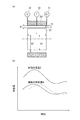
第1ステージ21と第2ステージ22との間には、図4(a)に示すように、円柱部23が位置する。
円柱部23の外周面と、加熱シリンダ201の内周面との間には、円筒状の検出流路Sが形成される。検出流路Sは、スクリュ10の軸心と同心に形成される。加熱シリンダ201には検出流路Sを軸方向に挟んで圧力センサ31,32が設けられている。
第1ステージ21において溶融された溶融樹脂Mは、円柱部23外周と加熱シリンダ201内壁の間の検出流路Sを通り、第2ステージ22へと流入する。後述するように、検出流路Sを流れる溶融樹脂Mの温度および検出流路Sの前後における圧力損失(圧力差)を検出し、検出値を用いて溶融樹脂Mの流量を算出する。
そして、検出流路Sを流れる溶融樹脂Mの温度を温度センサ33により検出する。温度センサ33による検出位置は、図では後方圧力センサ31による検出位置と前方圧力センサ32による検出位置との中間であるが、位置は特に制約されない。このとき、温度センサ33を加熱シリンダ201の内壁に露出させて、加熱シリンダ201の内部の溶融樹脂Mの温度を直接測定しても良いし、温度センサ33を加熱シリンダ201の内壁に露出させることなく、加熱シリンダ201の胴部温度を測定して溶融樹脂Mの温度として用いても良い。
もし、検出流路Sの前端側と後端側とで温度が相違するならば、前端側と後端側との各々において検出した温度を平均して用いてもよい。
Between the
A cylindrical detection channel S is formed between the outer peripheral surface of the
The molten resin M melted in the
Then, the temperature sensor 33 detects the temperature of the molten resin M flowing through the detection flow path S. The detection position by the temperature sensor 33 is intermediate between the detection position by the
If the temperatures at the front end side and the rear end side of the detection flow path S are different, the temperatures detected at the front end side and the rear end side may be averaged.
なお、図8(a)に示すように、相対的に後方に配置される後方圧力センサ31および相対的に前方に配置される前方圧力センサ32からなる圧力センサの組を複数組、加熱シリンダ201の軸方向に並べておき、スクリュ10の後退量に同期して、順次、より後方の圧力センサの組を用いるようにしても良い(図8(a)および(b)参照)。図8(a)および(b)では、測定に用いる圧力センサに「A」を付し、測定に用いない圧力センサに「N」を付している。この点、図8(c)および(d)でも同様である。
上記によると、ほぼ常にスクリュ10において検出流路Sを挟んだ同じ位置で圧力を検知できるので、溶融樹脂Mの流量を精度良く算出できる。このとき、各組の圧力センサ間の距離は同一にすることが好ましい。また各組の圧力センサを設ける周方向位置は、全て同じ位相でもよいし、各組それぞれ異なる位相でもよい。更に言えば複数組の圧力センサが同じ位相で、その他の複数組の圧力センサが異なる位相でもよい。
また、上記の後方圧力センサ31および前方圧力センサ32の組をなすことなく、図8(c)に示すように、加熱シリンダ201の軸方向に圧力センサ30を並べておき、スクリュ10の後退量に同期して、順次、円柱部23を挟む位置関係となる圧力センサ30を選択して用いるようにしてもよい(図8(c)および(d)参照)。これによっても図8(a)および(b)の場合と同様の効果が得られる。
図8に示す上記例では、加熱シリンダ201の軸方向に圧力センサを3つ以上並べるが、それに代えて、加熱シリンダ201の軸方向に移動可能な一組の圧力センサ31,32を設けることもできる。その場合、スクリュ10の後退に同期させて、円柱部23を間に挟むように圧力センサ31,32後退させることが好ましい。
As shown in FIG. 8 (a), a plurality of sets of pressure sensors each including a
According to the above, since the pressure can be detected almost always at the same position across the detection flow path S in the
Further, the
In the above example shown in FIG. 8, three or more pressure sensors are arranged in the axial direction of the
[繊維供給装置の形態]
繊維供給装置213は、スクリュ式あるいはピストン式などの計量フィーダーを用いることができる。この場合、加熱シリンダ201に繊維供給装置213を直接連結させ、加熱シリンダ201内に直接強化繊維Fを供給してもよいし、繊維受入口206に繊維供給用ホッパ205(図7(b))を設けて、繊維供給装置213から強化繊維Fを繊維供給用ホッパ205に供給してもよい。
[Configuration of fiber feeder]
The
計量フィーダーを加熱シリンダ201に直接連結する場合は、計量フィーダーの駆動力によって強化繊維Fを加熱シリンダ201内に押し込むことができるので、繊維受入口206内で強化繊維Fが絡み合ったとしても所定の供給量で、強化繊維Fをスクリュ10の溝内に充填できる。
繊維受入口206の清掃などのメインテナンスのために、計量フィーダーと加熱シリンダ201を簡易脱着可能な構造にしておくことが好ましい。
スクリュ式計量フィーダーを用いる場合は、スクリュが1本の単軸型のフィーダーでもスクリュが複数本の複数軸型フィーダーでも用いることができる。強化繊維Fを計量し安定して供給する搬送力が強く、強化繊維Fとフィーダー間の滑りを抑制できる複数軸型フィーダーが好ましく、特に構造がシンプルな2軸型フィーダーがコスト的にも設計的にも制御的にも好ましい。
When the weighing feeder is directly connected to the
For maintenance such as cleaning of the
When using a screw-type measuring feeder, a single-screw feeder with one screw or a multi-axial feeder with a plurality of screws can be used. A multi-axis feeder that has a strong conveying force to measure and stably supply the reinforcing fiber F and can suppress slippage between the reinforcing fiber F and the feeder is preferable. A biaxial feeder with a simple structure is particularly cost-effective. Moreover, it is preferable also in terms of control.
なお、複数軸型のフィーダーにおいてスクリュ式の計量フィーダーを用いる場合は、スクリュのフライトと溝が互いに噛み合う、いわゆる、2軸押出成形機式のフィーダースクリュでも、隔壁により独立した、あるいは、隔壁が無いが互いに干渉することなく独立したフィーダースクリュでもよい。2軸押出成形機式のフィーダースクリュを用いる場合のスクリュの回転方向は、同方向でも異方向でもよい。 In addition, when using a screw-type measuring feeder in a multi-axis type feeder, even a so-called biaxial extruder-type feeder screw, in which the screw flight and the groove mesh with each other, is independent of the partition or has no partition. May be independent feeder screws without interfering with each other. In the case of using a twin screw extruder-type feeder screw, the direction of rotation of the screw may be the same or different.
本実施形態の繊維供給装置213は、可塑化工程および射出工程を通じて強化繊維Fの供給を継続する。
本実施形態は、図1に示すように、2軸型スクリュフィーダー214を加熱シリンダ201に設け、強化繊維Fをスクリュ10の溝内に強制的に供給する。なお、単軸型のスクリュフィーダーを用いても支障がないことは言うまでもない。
また、強化繊維F表面の樹脂の濡れ性を大きくするために、スクリュフィーダーを図示しないヒータによって加熱してもよい。これにより、スクリュフィーダー内の強化繊維Fの温度が上昇し、溶融樹脂Mが強化繊維Fに接触したときに、溶融樹脂Mが温度低下して固化あるいは粘度が増大し、強化繊維Fの塊の中に溶融樹脂Mが浸入しにくくなるのを防止できる。これにより、強化繊維Fの繊維間に溶融樹脂Mが入り、繊維の束が解けて強化繊維Fの溶融樹脂M中への分散を促進できる。また強化繊維Fの温度を高温にすることにより溶融樹脂Mが強化繊維Fに付着しやすくなるので、スクリュ10の回転または前進に伴って強化繊維Fが繊維受入口206からシリンダ内に引き込まれる。
The
In the present embodiment, as shown in FIG. 1, a
In order to increase the wettability of the resin on the surface of the reinforcing fiber F, the screw feeder may be heated by a heater (not shown). Thereby, when the temperature of the reinforcing fiber F in the screw feeder rises and the molten resin M comes into contact with the reinforcing fiber F, the temperature of the molten resin M decreases and the solidification or viscosity increases. It is possible to prevent the molten resin M from entering the inside. Thereby, the molten resin M enters between the fibers of the reinforcing fiber F, the bundle of fibers is unwound, and the dispersion of the reinforcing fiber F into the molten resin M can be promoted. Further, since the temperature of the reinforcing fiber F is increased, the molten resin M easily adheres to the reinforcing fiber F, so that the reinforcing fiber F is drawn into the cylinder from the
また、2軸型スクリュフィーダー214への強化繊維Fの供給方法は、2軸型スクリュフィーダー214に連続繊維、いわゆるロービング状態の繊維(以下、ロービング繊維という)を直接投入してもよいし、予め所定長さに切断されたチョップドストランド状態の繊維(以下、チョップド繊維という)を投入してもよい。あるいは、ロービング繊維とチョップド繊維を所定の割合で混合して投入してもよい。
チョップド繊維を投入する場合は、計量フィーダーの繊維投入口付近までロービング繊維で搬送し、繊維投入口付近でロービング繊維を切断した直後に上記の計量フィーダーに投入してもよい。これにより、飛散しやすいチョップド繊維を成形機投入まで暴露することがないので作業性を向上できる。
本実施形態では、2軸型スクリュフィーダー214の繊維投入口付近に、ロービングカッター218を設ける。ロービングカッター218により、ロービング繊維を切断し、チョップド繊維にしてから2軸型スクリュフィーダー214に供給する。
The reinforcing fiber F can be supplied to the
When the chopped fiber is introduced, it may be conveyed to the vicinity of the fiber insertion port of the measuring feeder with the roving fiber, and may be input to the measuring feeder immediately after cutting the roving fiber in the vicinity of the fiber input port. Thereby, since the chopped fiber which is easily scattered is not exposed until the molding machine is charged, workability can be improved.
In this embodiment, a
また、ロービングカッター218は、2軸型スクリュフィーダー214に向けて回転する回転式カッターのものを使用する。これにより、切断したチョップド繊維をカッターの回転力を利用して、ホッパなどの強化繊維Fの貯留部材を介することなく、直接2軸型スクリュフィーダー214のスクリュ溝内に投入できる。これにより、切断直後の絡み合いの少ない状態のままチョップド繊維を2軸型スクリュフィーダー214に投入できるので、2軸型スクリュフィーダー214に効率よくチョップド繊維を食い込ませて、2軸型スクリュフィーダー214から安定してスクリュ10の溝内にチョップド繊維を供給できる。
The
[可塑化ユニットの動作]
可塑化ユニット200の概略の動作は以下の通りである。なお、図1を参照願いたい
加熱シリンダ201の内部に設けられたスクリュ10が回転されると、繊維供給装置213から繊維受入口206を介して供給された強化繊維F、および、樹脂供給ホッパ207から樹脂受入口208を介して供給された熱可塑性樹脂からなるペレット(樹脂ペレットP)は、加熱シリンダ201の前方側の吐出ノズル203側へ送り出される。この過程において、加熱され、溶融した樹脂ペレットP(溶融樹脂M)は強化繊維Fと混錬された後に、型締ユニット100の固定金型103と可動金型109の間に形成されるキャビティへ所定量だけ射出される。なお、スクリュ10を後退させながら可塑化を行った後に、前進することで射出を行うというスクリュ10の基本動作を伴うことは言うまでもない。また、加熱シリンダ201の外周には、樹脂ペレットPを溶融させるために図示しないヒータが設けられる。
[Operation of plasticizing unit]
The general operation of the
[射出成形の手順]
以上の要素を備える射出成形機1は、以下の手順で射出成形を行う。
射出成形は、よく知られているように、可動金型109と固定金型103を閉じて高圧で型締めする型締工程と、樹脂ペレットPを加熱シリンダ201内で加熱、溶融して可塑化させる可塑化工程と、可塑化された溶融樹脂Mを、可動金型109と固定金型103により形成されるキャビティに射出、充填する射出工程と、キャビティに充填された溶融樹脂Mが固化するまで冷却する保持工程と、金型を開放する型開き工程と、キャビティ内で冷却固化された成形品を取り出す取り出し工程と、を備え、上述した各工程をシーケンシャルに、あるいは一部平行させて実施して1サイクルが完了する。
[Injection molding procedure]
The injection molding machine 1 including the above elements performs injection molding according to the following procedure.
As is well known, the injection molding is performed by closing the
図3を参照しつつ、可塑化工程と射出工程について順に説明する。
[可塑化工程]
可塑化工程では、樹脂ペレットPを加熱シリンダ201の後方の樹脂供給ホッパ207から樹脂受入口208を介して加熱シリンダ201内に供給するとともに、繊維供給装置213から繊維受入口206を介して強化繊維Fを加熱シリンダ201内に供給する。
可塑化工程において、樹脂ペレットPおよび強化繊維Fの供給は継続して行われる。
可塑化開始当初、スクリュ10は、加熱シリンダ201の前端に位置しており、その初期位置からスクリュ10を回転させながら後退させる(図3(a)「可塑化開始」)。
スクリュ10と加熱シリンダ201の間に供給された樹脂ペレットPは、スクリュ10を回転させることで、せん断力を受けて加熱されながら徐々に溶融して、前方へと搬送される。繊維供給装置213の位置まで搬送された溶融樹脂Mは、繊維供給装置213から供給された強化繊維Fと混練されながらさらに前方へと搬送され、スクリュ10の前方に溜められる。その過程で、強化繊維Fの束がほぐれて溶融樹脂M中に分散される。
溶融樹脂Mが前方へと搬送されるのに伴って、溶融樹脂Mの圧力が次第に高められる。スクリュ10の前方に溜められた溶融樹脂Mの圧力と、スクリュ10の後退を抑制する背圧とをバランスさせながらスクリュ10を後退させる。
こうして必要な量の溶融樹脂Mが溜まったところで、スクリュ10の回転及び後退を停止する(図3(b)「可塑化完了」)。
The plasticizing step and the injection step will be described in order with reference to FIG.
[Plasticization process]
In the plasticizing step, the resin pellets P are supplied from the
In the plasticizing step, the supply of the resin pellets P and the reinforcing fibers F is continuously performed.
At the beginning of plasticization, the
The resin pellet P supplied between the
As the molten resin M is conveyed forward, the pressure of the molten resin M is gradually increased. The
When the necessary amount of the molten resin M is accumulated in this way, the rotation and retreat of the
図3は、樹脂(樹脂ペレットP,溶融樹脂M)と強化繊維Fの状態を、「未溶融樹脂」、「樹脂溶融」、「繊維分散」及び「繊維分散完了」の4段階に模式的に区別して示している。「可塑化完了」(図3(b))の段階では、スクリュ10よりも前方の「繊維分散完了」は、溶融樹脂Mの中に強化繊維Fが分散され、射出に供される状態を示し、「繊維分散」は、スクリュ10の回転に伴い、供給された強化繊維Fが溶融樹脂Mに分散されていることを示す。また、「樹脂溶融」は、樹脂ペレットPがせん断力を受けることで溶融し、「未溶融樹脂」はせん断力を受けるが、未だ溶融するには到っていないことを示している。
FIG. 3 schematically shows the state of the resin (resin pellet P, molten resin M) and the reinforcing fiber F in four stages of “unmelted resin”, “resin melt”, “fiber dispersion”, and “fiber dispersion complete”. Shown separately. At the stage of “plasticization completion” (FIG. 3B), “fiber dispersion completion” in front of the
[射出工程]
続く射出工程では、図3(c)に示すように、スクリュ10を前進させる。このときスクリュ10の先端部に備えられている図示しない逆流防止弁は閉鎖される。スクリュ10を前進させると、スクリュ10の前方に溜まった、強化繊維Fが分散した溶融樹脂Mの圧力(樹脂圧力)が上昇し、強化繊維Fが分散した溶融樹脂Mが吐出ノズル203からキャビティに向けて吐出される。
[Injection process]
In the subsequent injection process, the
〔本実施形態の主要な特徴〕
以下、本実施形態の主要な特徴について説明する。
さて、繊維強化樹脂においては、設計上の強度を得るため、樹脂に対して強化繊維Fが均一に分散し、樹脂および強化繊維Fを一定の比率で含有することが重要である。
繊維強化樹脂の成形品には、求められる強度の設計に基づいて、繊維含有率が定められている。
以下、繊維含有率は、重量を基準とする重量繊維含有率(weight of fiber contents)を指すものとする。重量繊維含有率は、繊維強化樹脂における樹脂の重量、樹脂に含有された強化繊維Fの重量の比率により定まる。
なお、重量繊維含有率に代えて、体積を基準とする体積繊維含有率(volume of fiber contents)を用いることもできる。
[Main features of this embodiment]
Hereinafter, main features of the present embodiment will be described.
In the fiber reinforced resin, in order to obtain design strength, it is important that the reinforcing fibers F are uniformly dispersed in the resin and the resin and the reinforcing fibers F are contained in a certain ratio.
In the fiber reinforced resin molded product, the fiber content is determined based on the required strength design.
Hereinafter, the fiber content refers to the weight of fiber contents based on weight. The weight fiber content is determined by the ratio of the weight of the resin in the fiber reinforced resin and the weight of the reinforced fiber F contained in the resin.
In place of the weight fiber content, a volume of fiber contents based on volume may be used.
繊維含有率の安定性を向上するためには、吐出ノズル203から吐出される溶融樹脂Mと強化繊維Fとの混合物の混合比率を安定させる必要がある。
ところで、強化繊維Fは、加熱シリンダ201内に強化繊維Fを供給するための繊維受入口206の直下(合流箇所J)に位置するスクリュ10の溝内で溶融樹脂Mに合流される。
供給された強化繊維Fは溶融樹脂Mに付着し、スクリュ10によって溶融樹脂Mと混練されることで次第にほぐれ、溶融樹脂Mに分散される。その過程で強化繊維Fは、所定の粘度を有する溶融樹脂Mにより捕捉されており、溶融樹脂Mと共に前方へと搬送される。
ここで、繊維供給装置213から供給される強化繊維Fは全て、合流箇所Jで溶融樹脂Mに合流するとともに、スクリュ10の溝内を逆流することなくスクリュ10前方に搬送されるため、吐出される混練物における混合比率は、合流する溶融樹脂Mと強化繊維Fとの比率(合流比率)によってほぼ決定される。
そうすると、溶融樹脂Mおよび強化繊維Fの合流比率が変動すれば、その比率変動が、吐出ノズル203から吐出される混合物の混合比率に影響する。
In order to improve the stability of the fiber content, it is necessary to stabilize the mixing ratio of the mixture of the molten resin M and the reinforcing fiber F discharged from the
By the way, the reinforcing fiber F is joined to the molten resin M in the groove of the
The supplied reinforcing fibers F adhere to the molten resin M, are gradually loosened by being kneaded with the molten resin M by the
Here, all the reinforcing fibers F supplied from the
Then, if the merging ratio of the molten resin M and the reinforcing fiber F varies, the ratio variation affects the mixing ratio of the mixture discharged from the
繊維供給装置213から供給される強化繊維Fの供給量が仮に一定であるとしても、強化繊維Fと合流する溶融樹脂Mの供給量(流量)が変動すれば、溶融樹脂Mおよび強化繊維Fの合流比率が変動する。
合流箇所Jにおける溶融樹脂Mの流量を算出するため、上述の検出流路Sを流れる溶融樹脂Mの圧力損失(圧力差)および温度を検出する。
ここで、合流箇所Jにおける溶融樹脂Mの圧力差および温度を用いて、合流箇所Jにおける流量を適切に算出できれば、検出流路Sを利用する必要がない。
しかし、合流箇所Jで圧力を測定する場合では、繊維供給装置213により強化繊維Fがスクリュ10の溝内の溶融樹脂Mに強制的に充填されることで、溶融樹脂Mの圧力が不規則に変動する。そのため、測定された溶融樹脂Mの圧力値が強化繊維Fの充填により影響を受けてしまい、合流箇所Jに後方から流入し、強化繊維Fと合流する溶融樹脂Mの流量の変動を適切に捉えることが難しい。
したがって、合流箇所Jよりも後方(繊維受入口206よりも後方に同じ)で溶融樹脂Mの圧力差を検出する必要がある。
以上より、繊維供給装置213による強制充填の影響を大きくは受けない程度に合流箇所Jから後方に離間し、溶融を終えた樹脂が流れる検出流路Sを、溶融樹脂Mの圧力差を検出する箇所として定める。
Even if the supply amount of the reinforcing fiber F supplied from the
In order to calculate the flow rate of the molten resin M at the junction J, the pressure loss (pressure difference) and temperature of the molten resin M flowing through the detection flow path S are detected.
Here, if the flow rate at the junction J can be calculated appropriately using the pressure difference and temperature of the molten resin M at the junction J, the detection flow path S need not be used.
However, when the pressure is measured at the junction J, the
Therefore, it is necessary to detect the pressure difference of the molten resin M behind the junction J (the same behind the fiber receiving port 206).
As described above, the pressure difference of the molten resin M is detected in the detection flow path S that is separated backward from the joining point J to the extent that the influence of the forced filling by the
また、円柱部23は、樹脂ペレットPの溶融を受け持つ第1ステージ21の終端(前端)に位置するため、円柱部23の周囲に位置する樹脂の状態は、図3(a)〜(c)に「樹脂溶融」と記載されているように、可塑化工程および射出工程を通じて溶融している。つまり、円柱部23の周囲の検出流路Sを流れるのは、完全に溶融した樹脂あるいは完全溶融に達しないまでも十分に軟化した半溶融樹脂を含んだ溶融樹脂である。
Moreover, since the
以上から、検出流路Sを流れる樹脂は、強化繊維Fや、樹脂ペレットPの溶け残った大きな塊を含まず、均質な流動性を有するので、流体理論に基づいて、補正等を加えることなく流量Qを容易に導くことができる。つまり、検出流路Sの入口の圧力P1と出口の圧力P2との差と、溶融樹脂Mの粘度を左右する溶融樹脂Mの温度Tとに基づいて、流量Qを適切に算出することができる。 From the above, the resin flowing through the detection flow path S does not include the large lumps of the reinforcing fibers F and the resin pellets P, and has a uniform fluidity, so that correction or the like is not made based on the fluid theory. The flow rate Q can be easily derived. That is, the flow rate Q can be appropriately calculated based on the difference between the inlet pressure P1 and the outlet pressure P2 of the detection flow path S and the temperature T of the molten resin M that affects the viscosity of the molten resin M. .
ここで、検出流路Sは円筒状であることから、検出流路Sの溶融樹脂Mの流れは、円筒状の流路の流量Qを求める式(1)に適合する。なお、図4(a)も参照されたい。
Q=π(R2+R1)(R2−R1)3(P1−P2)/(12ηL) ・・・(1)
R1 : 検出流路Sの内側半径
R2 : 検出流路Sの外側半径
P1 : 検出流路Sの入口側の圧力
P2 : 検出流路Sの出口側の圧力
η : 溶融樹脂Mの粘度
L : 検出流路Sの入口から出口までの距離
上記のR1、R2、およびLは既知であり、ηは、用いる樹脂の材質(例えば、ポリプロピレン、ポリエチレン等)と、温度センサ33により検出される温度Tとから定まる。
また、P1は後方圧力センサ31により検出され、P2は前方圧力センサ32により検出される。
Here, since the detection flow path S is cylindrical, the flow of the molten resin M in the detection flow path S conforms to Expression (1) for obtaining the flow rate Q of the cylindrical flow path. Please also refer to FIG.
Q = π (R2 + R1) (R2-R1) 3 (P1-P2) / (12ηL) (1)
R1: Inner radius of the detection channel S R2: Outer radius of the detection channel S P1: Pressure on the inlet side of the detection channel S P2: Pressure on the outlet side of the detection channel S η: Viscosity of the molten resin M L: Detection Distance from the entrance to the exit of the flow path S The above R1, R2, and L are known, and η is the material of the resin used (for example, polypropylene, polyethylene, etc.) and the temperature T detected by the temperature sensor 33 Determined from.
P1 is detected by the
圧力センサ31,32および温度センサ33により、検出流路Sを流れる溶融樹脂Mの圧力差および温度を継続して検出するとともに、式(1)より溶融樹脂Mの流量Qを算出する。
そうして得られた溶融樹脂Mの流量Qの時間的変化の一部を図4(b)に示す。
図4(b)に示すように、溶融樹脂Mの流量Qには、極大点および極小点を認めることができる。流量Qは、射出成形のサイクルタイムに対応するようにほぼ周期的に変化する。
上記のような流量Qの変動は、射出成形が進行する過程における溶融樹脂Mの圧力状態の変化に対応する。例えば、可塑化工程中、溶融樹脂Mは前方へと搬送されるのに伴ってスクリュのポンプ特性により圧力を高めていくので、検出流路Sを流れる溶融樹脂Mの圧力も次第に上昇する。また、可塑化工程が終了すると、スクリュ回転によるポンプ効果が無くなるので溶融樹脂Mの圧力は減少する。
なお、図4(b)は溶融樹脂Mの時間的変化を模式的に示しており、実際の流量Qは時々刻々と上下に変動する。
The
Part of the temporal change in the flow rate Q of the molten resin M thus obtained is shown in FIG.
As shown in FIG. 4B, a maximum point and a minimum point can be recognized in the flow rate Q of the molten resin M. The flow rate Q changes substantially periodically so as to correspond to the cycle time of injection molding.
The fluctuation of the flow rate Q as described above corresponds to a change in the pressure state of the molten resin M in the process of injection molding. For example, during the plasticizing process, as the molten resin M is transported forward, the pressure is increased by the pump characteristics of the screw, so that the pressure of the molten resin M flowing through the detection flow path S gradually increases. In addition, when the plasticizing process is completed, the pumping effect due to the screw rotation is lost, so the pressure of the molten resin M decreases.
FIG. 4B schematically shows the temporal change of the molten resin M, and the actual flow rate Q fluctuates up and down every moment.
上記のように、検出流路Sを流れ、合流箇所Jへと流入する溶融樹脂Mの流量Qが変動する。その流量Qの時間的変化に対して、図4(b)に破線で示すように強化繊維Fの供給量QF(単位時間あたりの供給量)を追従させるように制御する。 As described above, the flow rate Q of the molten resin M that flows through the detection flow path S and flows into the joining point J varies. Control is performed such that the supply amount Q F (supply amount per unit time) of the reinforcing fiber F follows the temporal change in the flow rate Q as shown by a broken line in FIG.
本実施形態では、強化繊維Fの供給に、駆動力を必要とする繊維供給装置213を用いるので、その駆動量を制御することで、供給量QFを可変に制御する。
事前に試験やシミュレーションを行い、繊維供給装置213の駆動量と供給量QFとの対応を示すテーブルデータを作成しておくことが好ましい。
In the present embodiment, the supply of reinforcing fibers F, since use of the
Advance were tested and simulation, it is preferable to create a table data indicating the correspondence between the supply amount Q F and the driving amount of the
上記のような追従制御は、制御部50が行う。
制御部50は、図5に示すように、溶融樹脂Mの流量Qを算出する樹脂流量算出部51と、流量Qに合わせて強化繊維Fの供給量QFを算出する繊維供給量算出部52と、供給量QFに応じた繊維供給装置213の駆動量を指示する制御指令を出す繊維供給制御部53とを備える。
制御部50は、コンピュータ・プログラム、または回路素子を組み込んだ電気回路・電子回路により構成される。
The
As shown in FIG. 5, the
The
図6を参照し、制御部50の各部51〜53の動作を説明する。
制御部50による繊維供給量の制御が開始されると、樹脂流量算出部51は、後方圧力センサ31、前方圧力センサ32、および温度センサ33から得られた検出値と、式(1)に基づいて流量Qを算出する(溶融樹脂の流量算出ステップS1)。
With reference to FIG. 6, operation | movement of each part 51-53 of the
When the control of the fiber supply amount by the
次に、繊維供給量算出部52は、樹脂流量算出部51により算出された流量Qに対して、所定の繊維含有率を実現するのに必要な強化繊維Fの供給量QFを算出する(繊維供給量算出ステップS2)。供給量QFは、流量Qに繊維含有率を乗じて求めることができる。供給量QFは、流量Qおよび繊維含有率の他、所定の補正値を用いて求めることができる。
Next, the fiber supply
次いで、繊維供給制御部53は、繊維供給量算出部52により算出された供給量QFに対応する繊維供給装置213の駆動量を指示する制御指令を繊維供給装置213へと送る(繊維供給制御ステップS3)。制御指令に基づいて繊維供給装置213の駆動量が制御される。
繊維供給装置213がスクリュフィーダーの場合は、制御指令により、スクリュフィーダーの回転数が制御される。
繊維供給装置213の駆動量が制御されることで、繊維供給装置213による強化繊維Fの供給量QFが制御される。
Then, the fiber
When the
By controlling the drive amount of the
ステップS3を終えたなら、ステップS1に戻る。樹脂流量算出部51は、各センサ31〜33により検出流路Sを流れる溶融樹脂Mの圧力差および温度を観測しながら、式(1)による流量Qの算出結果を継続して出力する。以降、ステップS2およびステップS3を上記と同様に行う。
以上のステップS1〜S3は、可塑化工程のみ、あるいは可塑化工程と射出工程を通じて継続して行われる。
When step S3 is completed, the process returns to step S1. The resin flow
The above steps S1 to S3 are continuously performed only through the plasticizing process or through the plasticizing process and the injection process.
上記の制御により、図4(b)に示すように、溶融樹脂Mの流量Qの時間的変化に対して、供給量QFが追従する。
つまり、溶融樹脂Mの流量Qが多いときは、強化繊維Fも多く供給され、溶融樹脂Mの流量Qが少ないときは、強化繊維Fも少なく供給されることとなる。
検出流路Sを流れる溶融樹脂Mの流量Qは、合流箇所Jへと後方から流入する溶融樹脂Mの流量と同等である。
そのため、溶融樹脂Mの流量Qの変動に応じて強化繊維Fの供給量QFが制御されることで、合流箇所Jでの強化繊維Fと溶融樹脂Mとの合流比率を一定にすることができる。
Controlled by, as shown in FIG. 4 (b), with respect to the temporal variation of the flow rate Q of the molten resin M, supply amount Q F to follow.
That is, when the flow rate Q of the molten resin M is large, a large amount of reinforcing fiber F is supplied, and when the flow rate Q of the molten resin M is small, a small amount of reinforcing fiber F is also supplied.
The flow rate Q of the molten resin M that flows through the detection flow path S is equal to the flow rate of the molten resin M that flows into the junction J from behind.
Therefore, to be a constant confluence percentage of that supply quantity Q F of the reinforcing fibers F in accordance with the variation of the flow rate Q of the molten resin M is controlled, the reinforcing fibers F at the joining portion J and the molten resin M it can.
以上で説明したように、本実施形態では、強化繊維Fとの合流箇所Jへと後方から流入する溶融樹脂Mの流量Qに応じて強化繊維Fの供給量QFを可変に制御することにより、溶融樹脂Mの流量Qが変動しても、溶融樹脂Mおよび強化繊維Fの合流比率を一定に保つことができる。合流比率は、その後、強化繊維Fおよび溶融樹脂Mが共に搬送される過程でも引き継がれるので、吐出ノズル203から吐出される強化繊維Fおよび溶融樹脂Mの混合比率を安定させることができる。その結果、得られた成形品の繊維含有率の安定性を向上させることができる。
As described above, in the present embodiment, the supply amount QF of the reinforcing fiber F is variably controlled according to the flow rate Q of the molten resin M flowing from the rear to the joining point J with the reinforcing fiber F. Even if the flow rate Q of the molten resin M fluctuates, the joining ratio of the molten resin M and the reinforcing fibers F can be kept constant. Thereafter, the joining ratio is inherited even in the process in which both the reinforcing fiber F and the molten resin M are conveyed, so that the mixing ratio of the reinforcing fiber F and the molten resin M discharged from the
また、本実施形態では、スクリュ10の第1ステージ21と第2ステージ22との間に位置する円柱部23と加熱シリンダ201との間の検出流路Sを流れる溶融樹脂Mの圧力差および温度を用いて溶融樹脂Mの流量Qを算出する。
ここで、第1ステージ21において樹脂の溶融が完了するので、円柱部23の位置では樹脂が溶融している。
加えて、円柱部23が可塑化工程および射出工程を通じて繊維受入口206よりも後方に位置するので、検出流路Sには強化繊維Fが入り込まない。
したがって、検出流路Sには溶融樹脂Mだけが流れるので、検出流路Sを流れる溶融樹脂Mの流量Qを適切に把握できる。その流量Qに応じて、強化繊維Fの供給量QFを適切に制御することができる。また、圧力センサ31,32部には強化繊維Fが入らないので、強化繊維Fによる圧力センサ31,32の摩耗による短命化も防止できる。
Further, in the present embodiment, the pressure difference and temperature of the molten resin M flowing in the detection flow path S between the
Here, since the melting of the resin is completed in the
In addition, the reinforcing fiber F does not enter the detection flow path S because the
Therefore, since only the molten resin M flows through the detection flow path S, the flow rate Q of the molten resin M flowing through the detection flow path S can be properly grasped. According to the flow rate Q, the supply amount Q F of the reinforcing fiber F can be appropriately controlled. Further, since the reinforcing fibers F do not enter the
ところで、スクリュ10の回転によるスクリュ10の溝内の圧力測定値は、スクリュ10の1回転を1周期として圧力変動する、具体的には測定圧力波形が鋸歯状の様態となる。よって、溶融樹脂Mの流量Qを算出するための圧力値として、鋸歯の上限値あるいは下限値あるいは平均値のいずれを用いてもよい。
By the way, the pressure measurement value in the groove of the
〔第2実施形態〕
本実施形態では、第1実施形態と同様の射出成形機1を用いる。但し、スクリュ10の後退による円柱部23の移動に伴って加熱シリンダ201に対する検出流路Sの位置が変わっても、出来るだけ2つの圧力センサの間に検出流路Sを軸方向に挟んで溶融樹脂Mの圧力を検出できるように圧力センサを複数設ける(図8)のではなく、検出流路Sよりも後方の少なくとも2カ所で測定した圧力に基づいて、溶融樹脂Mの流量Qを推定する。以下では、第1実施形態と異なる点を中心に説明する。
本実施形態においても、第1実施形態と同様、圧力センサ31,32は加熱シリンダ201に固定されるが、圧力センサ31,32(図9)はどちらも、検出流路Sより後方に設けられる。より具体的に、圧力センサ31,32は、スクリュ10が最大に後退したときの円柱部23の位置よりも少し後方に位置する。
本実施形態では、検出流路Sよりも後方で、相対的に後方に位置する圧力センサ31の圧力P1と、相対的に前方に位置する圧力センサ32の圧力P2の差から、スクリュ10と一体でスクリュ10と共に後退する検出流路Sの手前に位置する仮想点X3の圧力P3を例えば外挿により推定する(図10(a))。
加熱シリンダ201に設けられた圧力センサ31,32と検出流路Sとの相対位置は、機械的な組み付け状態により一意に決まっている。また、一般に第1ステージ21の前端側における可塑化時の溶融樹脂Mの圧力は、スクリュのポンプ特性により前方に向かうほど、つまり圧力センサ31,32から見て検出流路Sに近くなるほど、略比例して上昇することが知られている。これを利用して、圧力P1と圧力P2の差と、圧力センサ31と検出流路Sとの相対位置(あるいは圧力センサ32と検出流路Sとの相対位置)に基づいて、検出流路Sの手前に位置する仮想点X3の圧力P3を例えば外挿により推定する(図10(b))。
スクリュと共に後退する検出流路Sでは可塑化が進む、つまりスクリュ10の後退量が大きくなるにつれて(あるいは可塑化時間の経過に伴って)、検出流路Sは圧力センサ32に近づいてくる。このことは、圧力P3の値が圧力P2の値に近づくことを意味している(図10(b))。
以上により、スクリュ10の後退に追従して、検出流路Sの手前に位置する仮想点X3の圧力P3を得ることができる。
ところで、検出流路部の前方側である2ndステージの供給部(繊維受入口206)は、強化繊維を充填するために大気圧程度まで減圧することが好ましい。この場合、本実施形態においては、圧力P3と大気圧との圧力差を用いて流量Qを計算することができる。
また、スクリュ10の後退開始から後退完了まで、つまり可塑化工程を通じて検出流路Sよりも前方側に位置する加熱シリンダ201の或る箇所に、別の圧力センサを設けて圧力を測定すれば、第1実施形態のように検出流路Sを挟んだ前後の圧力差として、その圧力センサの測定圧力と圧力P3との圧力差を求めることができる。その圧力差を用いて、流量Qを計算することにより、第1実施形態で述べたのと同様の作用効果が得られ、更に流量Qの計算精度を向上させることができる。
[Second Embodiment]
In the present embodiment, the same injection molding machine 1 as in the first embodiment is used. However, even if the position of the detection flow path S with respect to the
Also in this embodiment, the
In the present embodiment, the
The relative position between the
In the detection flow path S that retreats together with the screw, plasticization proceeds, that is, as the retraction amount of the
As described above, the pressure P3 of the virtual point X3 located in front of the detection flow path S can be obtained following the retreat of the
By the way, it is preferable that the 2nd stage supply section (fiber receiving port 206) on the front side of the detection flow path section is decompressed to about atmospheric pressure in order to fill the reinforcing fibers. In this case, in the present embodiment, the flow rate Q can be calculated using the pressure difference between the pressure P3 and the atmospheric pressure.
Further, if the pressure is measured by providing another pressure sensor at a certain position of the
〔第3実施形態〕
本実施形態でも、第1実施形態の射出成形機1を用いる。但し、検出流路Sよりも後方の1カ所で、1つの圧力センサ31(図11)により測定した圧力に基づいて、溶融樹脂Mの流量Qを推定する。以下では、第1実施形態と異なる点を中心に説明する。
圧力センサ31は、第1実施形態と同様に加熱シリンダ201に固定される。
加熱シリンダ201に設けられた圧力センサ31と検出流路Sとの相対位置は、機械的な組み付け状態により一意に決まっている。また、一般に第1ステージ21の前端側における可塑化時の溶融樹脂Mの圧力は、スクリュのポンプ特性により前方に向かうほど、つまり圧力センサ31から見て検出流路Sに近くなるほど、略比例して上昇することが知られている。これを利用して、予め実験により圧力P1の変化を測定しておき、圧力P1の変化と、圧力センサ31と検出流路Sとの相対位置に基づいて、検出流路Sの手前に位置する仮想点X3の圧力P3を例えば外挿により推定する(図12)。
以上により、スクリュ10の後退に追従して、検出流路Sの手前の仮想点X3の圧力P3を得ることができる。このとき、2ndステージの供給部(繊維受入口206)を大気圧程度まで減圧した場合は、圧力P3と大気圧との圧力差を用いて流量Qを計算することができる。また、スクリュ10の後退開始から後退完了まで、つまり可塑化工程を通じて検出流路Sよりも前方側に位置する加熱シリンダ201の或る箇所に、別の圧力センサを設けて圧力を測定すれば、第1実施形態のように検出流路Sを挟んだ前後の圧力差として、その圧力センサの測定圧力と圧力P3との圧力差を求めることができる。その圧力差を用いて、流量Qを計算することにより、第1実施形態で述べたのと同様の作用効果が得られ、更に流量Qの計算精度を向上させることができる。
[Third Embodiment]
Also in this embodiment, the injection molding machine 1 of the first embodiment is used. However, the flow rate Q of the molten resin M is estimated based on the pressure measured by one pressure sensor 31 (FIG. 11) at one location behind the detection flow path S. Below, it demonstrates centering on a different point from 1st Embodiment.
The
The relative position between the
Thus, the pressure P3 at the virtual point X3 before the detection flow path S can be obtained following the retreat of the
本実施形態は、種々の改変を加えることが可能である。
検出流路Sが円筒形であることにより、式(1)を利用して流量Qを求めることができるが、検出流路Sの形状は、円筒形に限らない。例えば、円柱部23の外周面の一部に形成された突起や窪みに対応する形状に検出流路Sが形成されるとしても、実験やシミュレーションにより、圧力差および温度と流量との相関関係より、検出流路Sを流れる溶融樹脂Mの流量Qを求めることができる。
また、円柱部23に限らず加熱シリンダ201の軸線方向の所定箇所の内周面と、スクリュ10の外周(例えば、フライト頂面)との間に形成される空間を検出流路Sとして用いることも本発明は許容する。
したがって、円柱部23は本発明に必須ではない。
ここで、スクリュ10に円柱部23を形成するにしても、その位置は第1ステージ21および第2ステージ22の間には限定されない。
This embodiment can be modified in various ways.
Since the detection flow path S is cylindrical, the flow rate Q can be obtained using Equation (1), but the shape of the detection flow path S is not limited to the cylindrical shape. For example, even if the detection flow path S is formed in a shape corresponding to a protrusion or a depression formed on a part of the outer peripheral surface of the
Further, not only the
Therefore, the
Here, even if the
本実施形態では、可塑化工程および射出工程を通じて強化繊維Fの供給を継続する場合、可塑化工程および射出工程を通じて供給量QFを流量Qに追従させる制御を行うので、可塑化工程および射出工程の全期間において合流比率を一定に保つことができる。このようにすると、混合比率が一定に安定した混練物を連続して射出することができるので、繊維含有率の安定性を向上させる効果が最も高い。
但し、本発明は、可塑化工程および射出工程の一部の期間において強化繊維Fの供給を停止したり、その一部の期間において供給量QFの制御を停止し、予め定められた供給量で強化繊維Fを供給することを許容する。そのようにしても、残りの期間において強化繊維Fの供給量QFが制御されることにより混合比率の安定が図られるので、繊維含有率の安定性向上に寄与できる。
In the present embodiment, when the supply of the reinforcing fiber F is continued through the plasticizing step and the injection step, the supply amount Q F is controlled to follow the flow rate Q through the plasticizing step and the injection step. The merging ratio can be kept constant throughout the period. In this way, since the kneaded material having a constant mixing ratio can be continuously injected, the effect of improving the stability of the fiber content is the highest.
However, the present invention is, stop the supply of the reinforcing fibers F in some periods of the plasticizing step and injection step, and stops the control of the supply amount Q F at a part of the period, the supply amount previously determined It is allowed to supply the reinforcing fiber F. Even in such a case, the mixing ratio can be stabilized by controlling the supply amount Q F of the reinforcing fiber F in the remaining period, which can contribute to an improvement in the stability of the fiber content.
また、本実施形態では、樹脂流量算出部51により流量Qを算出した直後に、強化繊維Fの供給量QFを算出するが、流量Qの算出時点で円柱部23の周囲に存在した溶融樹脂Mが合流箇所Jに到達するのに要する時間(到達所要時間)に応じて、流量Qに対する強化繊維Fの供給量QFの応答を遅延させてもよい(図4(b)の一点鎖線参照)。
上記のように制御するためには、流量Qの時間的変化を記憶しておき、到達所要時間だけ遡った時刻に検出された流量Qに応じて強化繊維Fの供給量QFを算出すればよい。
Further, in this embodiment, immediately after the flow rate Q is calculated by the resin flow
In order to perform the control as described above, the temporal change in the flow rate Q is stored, and the supply amount Q F of the reinforcing fiber F is calculated according to the flow rate Q detected at a time traced back by the required arrival time. Good.
上述の通り、本実施形態は、合流箇所Jへと後方から流入する溶融樹脂Mの所定箇所における圧力差および温度を用いて流量Qを算出し、流量Qに応じて強化繊維Fの供給量QFを可変に制御する。
そのため、射出成形のプロセス中に実測された溶融樹脂Mの圧力差および温度から算出された流量Qに基づいて、実機および実際のプロセスに即した制御を行うことが可能であるが、本発明は、実験やシミュレーションに基づいて予め設定された流量Qを取得し、強化繊維Fの供給量QFの制御に用いることも許容する。
また、予め実験により、例えば、射出成形の1サイクル分についての流量Qをテーブルデータに設定しておくことで、オンタイムの実測値から流量Qを算出せずとも、十分実用に耐える制御を行うことができる。
As described above, in the present embodiment, the flow rate Q is calculated using the pressure difference and the temperature at a predetermined location of the molten resin M flowing from the rear to the joining location J, and the supply amount Q of the reinforcing fibers F according to the flow rate Q. F is controlled variably.
Therefore, based on the flow rate Q calculated from the pressure difference and temperature of the molten resin M actually measured during the injection molding process, it is possible to perform control according to the actual machine and the actual process. The flow rate Q set in advance based on experiments and simulations is acquired and used for controlling the supply amount Q F of the reinforcing fiber F.
In addition, by performing an experiment in advance, for example, by setting the flow rate Q for one cycle of injection molding in the table data, it is possible to control to withstand practical use without calculating the flow rate Q from the on-time measured value. be able to.
強化繊維Fを供給する装置の形態としては、図7(a)に示す構成または図7(b)に示す構成をも採用することができる。
図7(a)は、繊維供給装置としての単軸型スクリュフィーダー216を示す。このように単軸型スクリュフィーダー216を繊維受入口206に連通して設けて強化繊維Fを供給することもできる。単軸型スクリュフィーダー216により、強化繊維Fがスクリュ10の溝内に強制的に供給される。
As a form of the apparatus which supplies the reinforced fiber F, the structure shown to Fig.7 (a) or the structure shown to FIG.7 (b) is also employable.
Fig.7 (a) shows the single axis | shaft
一方、繊維供給用ホッパ205を介して強化繊維Fを供給する場合は、繊維供給装置213として、図7(b)に示すようなベルトフィーダ217を用いることができる。ベルトフィーダ217の搬送速度を調節することにより、強化繊維Fを所定の量だけ繊維供給用ホッパ205に供給できる。
ここで、ベルトフィーダ217から繊維供給用ホッパ205に強化繊維Fを供給する場合は、繊維受入口206内で強化繊維Fが絡み合わない程度の供給量、具体的には繊維受入口206を充満させない程度に強化繊維Fの供給量に制限することによって、繊維受入口206内を閉塞させることなく、強化繊維Fをスクリュ10内に充填できる。これにより、強化繊維Fに負荷を与えることなく、スクリュ10の溝内に供給できるので、スクリュ10の溝内に投入する前の繊維折損を抑制できる。
On the other hand, when the reinforcing fiber F is supplied through the
Here, when the reinforcing fiber F is supplied from the
また、本発明で用いるスクリュは、上記実施形態のスクリュ10には限定されず、種々の形態を採ることができる。本発明のスクリュは、第1ステージ21および第2ステージ22を備えた2ステージ型には限定されない。
また、スクリュ10は、リードが相違する第1フライト27および第2フライト28を備えるが、本発明のスクリュは、単一のリードを有する1種類のフライトを備えるものであってもよい。
スクリュの形態が変われば、樹脂の溶融状態も変わる。そのため、検出流路Sを通過する溶融樹脂Mが完全には溶融しておらず、圧力差および温度の検出には支障のない溶け残りを含むことも本発明は許容する。
Moreover, the screw used by this invention is not limited to the
Moreover, although the
If the screw shape changes, the molten state of the resin also changes. For this reason, the present invention allows the molten resin M passing through the detection flow path S to be not completely melted and to contain unmelted residue that does not hinder the detection of the pressure difference and temperature.
また、本発明に適用される樹脂原料、強化繊維は、いずれも特に限定されない。
樹脂原料としては、ポリプロピレンやポリエチレンなどの汎用樹脂や、ポリアミドやポリカーボネートなどのエンジニアリングプラスチックなどの公知の樹脂を広く用いることができる。
また、強化繊維としては、ガラス繊維、炭素繊維、竹繊維、麻繊維などの公知の繊維を広く用いることができる。
Moreover, neither the resin raw material nor the reinforcing fiber applied to the present invention is particularly limited.
As the resin raw material, known resins such as general-purpose resins such as polypropylene and polyethylene and engineering plastics such as polyamide and polycarbonate can be widely used.
As the reinforcing fiber, known fibers such as glass fiber, carbon fiber, bamboo fiber, hemp fiber can be widely used.
上記以外にも、本発明の主旨を逸脱しない限り、上記実施の形態で挙げた構成を取捨選択したり、他の構成に適宜変更することが可能である。 In addition to the above, the configurations described in the above embodiments can be selected or modified as appropriate to other configurations without departing from the gist of the present invention.
本発明は、射出成形の他に、押出成形にも応用することができる。その押出成形装置は、スクリュが進退されないことを除いて、本発明の射出成形装置と同様に構成することができる。 The present invention can be applied to extrusion molding in addition to injection molding. The extrusion molding apparatus can be configured in the same manner as the injection molding apparatus of the present invention except that the screw is not advanced or retracted.
1 射出成形機
10 スクリュ
21 第1ステージ
22 第2ステージ
23 円柱部
24 圧縮部
25 供給部
26 圧縮部
27 第1フライト
28 第2フライト
29 供給部
31 後方圧力センサ
32 前方圧力センサ
33 温度センサ
50 制御部
51 樹脂流量算出部(樹脂流量取得部)
52 繊維供給量算出部(繊維供給量取得部)
53 繊維供給制御部
100 型締ユニット
101 ベースフレーム
103 固定金型
105 固定ダイプレート
107 摺動部材
109 可動金型
111 可動ダイプレート
113 油圧シリンダ
115 タイバー
117 油圧シリンダ
119 ラム
121 雄ねじ部
123 ナット
200 可塑化ユニット
201 加熱シリンダ(シリンダ)
203 吐出ノズル
205 繊維供給用ホッパ
206 繊維受入口
207 樹脂供給ホッパ(樹脂供給部)
208 樹脂受入口
209 第1電動機
211 第2電動機
213 繊維供給装置(繊維供給部)
214 2軸型スクリュフィーダー
215 ペレット供給装置
216 単軸型スクリュフィーダー
217 ベルトフィーダ
218 ロービングカッター
F 強化繊維
J 合流箇所
L1 第1リード
L2 第2リード
P 樹脂ペレット(樹脂原料)
Q 流量
QF 供給量
S 検出流路
S1 流量算出ステップ(流量取得ステップ)
S2 繊維供給量算出ステップ(繊維供給量取得ステップ)
S3 繊維供給制御ステップ
DESCRIPTION OF SYMBOLS 1
52 Fiber supply amount calculation unit (fiber supply amount acquisition unit)
53 Fiber
203
208
214
Q flow rate Q F supply amount S detection flow path S1 flow rate calculation step (flow rate acquisition step)
S2 Fiber supply amount calculation step (fiber supply amount acquisition step)
S3 Fiber supply control step
Claims (5)
前記シリンダの内部に、回転および回転軸方向に移動可能に設けられたスクリュと、
前記シリンダに形成された樹脂受入口を介して前記シリンダ内に樹脂原料を供給する樹脂供給部と、
前記シリンダにおいて前記樹脂受入口よりも前方側に形成された繊維受入口を介して前記シリンダ内に強化繊維を供給する繊維供給部と、
前記繊維受入口を介して前記シリンダ内に供給され、後方から流入した前記樹脂原料に合流される前記強化繊維の供給量を、前記繊維受入口よりも後方で前記シリンダの軸線方向の所定箇所と前記スクリュとの間を流れる、溶融した前記樹脂原料の流量に応じて可変に制御する制御部と、を備え、
前記制御部は、
前記所定箇所と前記スクリュとの間を流れる前記樹脂原料の圧力損失および温度の各々の検出値を用いて前記流量を取得し、取得された前記流量に応じて前記強化繊維の前記供給量を可変に制御する、
ことを特徴とする繊維強化樹脂の射出成形装置。 A cylinder provided with a discharge nozzle on the front side;
A screw provided inside the cylinder so as to be rotatable and movable in the direction of the rotation axis;
A resin supply section for supplying a resin raw material into the cylinder via a resin receiving port formed in the cylinder;
A fiber supply unit for supplying reinforcing fibers into the cylinder through a fiber receiving port formed on the front side of the resin receiving port in the cylinder;
A supply amount of the reinforcing fibers supplied into the cylinder through the fiber receiving port and joined to the resin raw material flowing in from the rear is set to a predetermined position in the axial direction of the cylinder behind the fiber receiving port. A controller that variably controls according to the flow rate of the molten resin raw material flowing between the screws ,
The controller is
The flow rate is acquired using detected values of the pressure loss and temperature of the resin raw material flowing between the predetermined portion and the screw, and the supply amount of the reinforcing fiber is variable according to the acquired flow rate. To control,
A fiber-reinforced resin injection molding apparatus characterized by the above.
請求項1に記載の繊維強化樹脂の射出成形装置。 Between the outer periphery of the inner periphery and the screw of said predetermined portion of said cylinder, a cylindrical flow path is formed,
The fiber-reinforced resin injection molding apparatus according to claim 1.
前記樹脂原料の前記流量を取得する流量取得部と、
前記流量および所定の繊維含有率を用いて前記強化繊維の前記供給量を取得する繊維供給量取得部と、
前記供給量に対応する前記繊維供給部の駆動量を指示する制御指令を出す繊維供給部制御部と、を備える、
請求項2に記載の繊維強化樹脂の射出成形装置。 The controller is
A flow rate acquisition unit for acquiring the flow rate of the resin raw material;
A fiber supply amount acquisition unit that acquires the supply amount of the reinforcing fibers using the flow rate and a predetermined fiber content;
A fiber supply unit control unit that issues a control command that instructs a drive amount of the fiber supply unit corresponding to the supply amount;
An injection molding apparatus for fiber reinforced resin according to claim 2 .
前記強化繊維および前記樹脂原料が合流する箇所よりも後方で前記シリンダの軸線方向の所定箇所と前記スクリュとの間を流れる前記樹脂原料の圧力損失および温度の各々の検出値を用いて、溶融した前記樹脂原料の流量を取得し、取得された前記流量に応じて、
前記シリンダ内に供給され、後方から流入した前記樹脂原料に合流される前記強化繊維の供給量を可変に制御する、
ことを特徴とする繊維強化樹脂の射出成形方法。 An injection nozzle is provided on the front side, and injection molding is performed using a resin raw material supplied into a cylinder in which a screw is disposed inside and a reinforcing fiber supplied in front of the resin raw material into the cylinder. A method,
Using the detected values of the pressure loss and temperature of the resin raw material flowing between the screw and the predetermined location in the axial direction of the cylinder behind the location where the reinforcing fiber and the resin raw material merge, Acquire the flow rate of the resin raw material, and according to the acquired flow rate,
The supplied into the cylinder and variable control of the supply amount of the reinforcing fibers to be merged into the resin material flowing from the rear,
An injection molding method of a fiber reinforced resin characterized by the above.
取得された前記流量および所定の繊維含有率を用いて前記強化繊維の前記供給量を取得する繊維供給量取得ステップと、
取得された前記供給量により前記強化繊維を供給させる繊維供給制御ステップと、を備える、
請求項4に記載の繊維強化樹脂の射出成形方法。 A resin flow rate obtaining step for obtaining the flow rate of the resin raw material;
A fiber supply amount acquisition step of acquiring the supply amount of the reinforcing fibers using the acquired flow rate and a predetermined fiber content;
A fiber supply control step of supplying the reinforcing fibers according to the acquired supply amount,
An injection molding method for a fiber reinforced resin according to claim 4 .
Priority Applications (1)
| Application Number | Priority Date | Filing Date | Title |
|---|---|---|---|
| JP2013217956A JP5913251B2 (en) | 2013-10-21 | 2013-10-21 | Fiber-reinforced resin injection molding apparatus and injection molding method |
Applications Claiming Priority (1)
| Application Number | Priority Date | Filing Date | Title |
|---|---|---|---|
| JP2013217956A JP5913251B2 (en) | 2013-10-21 | 2013-10-21 | Fiber-reinforced resin injection molding apparatus and injection molding method |
Publications (2)
| Publication Number | Publication Date |
|---|---|
| JP2015080851A JP2015080851A (en) | 2015-04-27 |
| JP5913251B2 true JP5913251B2 (en) | 2016-04-27 |
Family
ID=53011736
Family Applications (1)
| Application Number | Title | Priority Date | Filing Date |
|---|---|---|---|
| JP2013217956A Active JP5913251B2 (en) | 2013-10-21 | 2013-10-21 | Fiber-reinforced resin injection molding apparatus and injection molding method |
Country Status (1)
| Country | Link |
|---|---|
| JP (1) | JP5913251B2 (en) |
Families Citing this family (3)
| Publication number | Priority date | Publication date | Assignee | Title |
|---|---|---|---|---|
| JP7297215B2 (en) | 2020-01-30 | 2023-06-26 | 広島県 | Arithmetic Device, Arithmetic Processing Program, and Arithmetic Method |
| WO2021157264A1 (en) * | 2020-02-04 | 2021-08-12 | 株式会社日本製鋼所 | Injection molding method and injection molding device |
| CN117124553A (en) * | 2022-08-25 | 2023-11-28 | 西诺控股集团有限公司 | Injection molding machine structure precisely controlled through digital hydraulic oil cylinder |
Family Cites Families (3)
| Publication number | Priority date | Publication date | Assignee | Title |
|---|---|---|---|---|
| JP2005014272A (en) * | 2003-06-24 | 2005-01-20 | Yokohama Rubber Co Ltd:The | Structure of plasticizing screw for injection blow apparatus |
| DE102008061270B4 (en) * | 2008-12-10 | 2010-09-23 | Karl Hehl | Device and method for the production of molded parts from plastifiable material and from fibrous inserts |
| EP2633972B1 (en) * | 2010-10-25 | 2015-10-21 | Mitsubishi Heavy Industries Plastic Technology Co., Ltd. | Plasticizing screw for injection molding and injection molding method using same |
-
2013
- 2013-10-21 JP JP2013217956A patent/JP5913251B2/en active Active
Also Published As
| Publication number | Publication date |
|---|---|
| JP2015080851A (en) | 2015-04-27 |
Similar Documents
| Publication | Publication Date | Title |
|---|---|---|
| JP5894336B2 (en) | Injection molding method and injection molding apparatus | |
| JP6130533B2 (en) | Injection molding apparatus and injection molding method | |
| JP5940740B1 (en) | Injection molding method and injection molding machine | |
| EP2735418B1 (en) | Injection molding machine and raw material metering unit | |
| EP2050554B1 (en) | Integral equipment comprising kneading and injection sections | |
| WO2016075846A1 (en) | Injection molding method and injection molding apparatus | |
| JP5913251B2 (en) | Fiber-reinforced resin injection molding apparatus and injection molding method | |
| CN111231252B (en) | Molding machine and method of molding parts | |
| KR102269352B1 (en) | Injection molding machine | |
| CN104647714A (en) | Controller For Injection Molding Machine | |
| CN112571737A (en) | Control device and control method for injection molding machine | |
| CN103770302A (en) | Injection molding machine | |
| JP5913075B2 (en) | Plasticizing apparatus, injection molding apparatus and injection molding method | |
| CN108698293B (en) | Method of molding parts | |
| JP2014184702A (en) | Injection molding method and device | |
| JP5889358B2 (en) | Injection molding machine |
Legal Events
| Date | Code | Title | Description |
|---|---|---|---|
| A625 | Written request for application examination (by other person) |
Free format text: JAPANESE INTERMEDIATE CODE: A625 Effective date: 20150710 |
|
| A131 | Notification of reasons for refusal |
Free format text: JAPANESE INTERMEDIATE CODE: A131 Effective date: 20151021 |
|
| A521 | Request for written amendment filed |
Free format text: JAPANESE INTERMEDIATE CODE: A523 Effective date: 20151202 |
|
| TRDD | Decision of grant or rejection written | ||
| A01 | Written decision to grant a patent or to grant a registration (utility model) |
Free format text: JAPANESE INTERMEDIATE CODE: A01 Effective date: 20160302 |
|
| A61 | First payment of annual fees (during grant procedure) |
Free format text: JAPANESE INTERMEDIATE CODE: A61 Effective date: 20160401 |
|
| R150 | Certificate of patent or registration of utility model |
Ref document number: 5913251 Country of ref document: JP Free format text: JAPANESE INTERMEDIATE CODE: R150 |
|
| S533 | Written request for registration of change of name |
Free format text: JAPANESE INTERMEDIATE CODE: R313533 |
|
| R350 | Written notification of registration of transfer |
Free format text: JAPANESE INTERMEDIATE CODE: R350 |
|
| S111 | Request for change of ownership or part of ownership |
Free format text: JAPANESE INTERMEDIATE CODE: R313114 |
|
| R350 | Written notification of registration of transfer |
Free format text: JAPANESE INTERMEDIATE CODE: R350 |
|
| R250 | Receipt of annual fees |
Free format text: JAPANESE INTERMEDIATE CODE: R250 |
|
| R250 | Receipt of annual fees |
Free format text: JAPANESE INTERMEDIATE CODE: R250 |
|
| R250 | Receipt of annual fees |
Free format text: JAPANESE INTERMEDIATE CODE: R250 |
|
| S111 | Request for change of ownership or part of ownership |
Free format text: JAPANESE INTERMEDIATE CODE: R313115 |
|
| R350 | Written notification of registration of transfer |
Free format text: JAPANESE INTERMEDIATE CODE: R350 |
|
| R250 | Receipt of annual fees |
Free format text: JAPANESE INTERMEDIATE CODE: R250 |
|
| R250 | Receipt of annual fees |
Free format text: JAPANESE INTERMEDIATE CODE: R250 |