JP5911235B2 - toner - Google Patents
toner Download PDFInfo
- Publication number
- JP5911235B2 JP5911235B2 JP2011186357A JP2011186357A JP5911235B2 JP 5911235 B2 JP5911235 B2 JP 5911235B2 JP 2011186357 A JP2011186357 A JP 2011186357A JP 2011186357 A JP2011186357 A JP 2011186357A JP 5911235 B2 JP5911235 B2 JP 5911235B2
- Authority
- JP
- Japan
- Prior art keywords
- toner
- particles
- silica particles
- silica
- mass
- Prior art date
- Legal status (The legal status is an assumption and is not a legal conclusion. Google has not performed a legal analysis and makes no representation as to the accuracy of the status listed.)
- Active
Links
Images

Description
本発明は、電子写真法および静電記録法に用いられるトナーに関する。 The present invention relates to a toner used in electrophotography and electrostatic recording.
高画質を要求されるフルカラー複写機またはフルカラープリンタ等のフルカラー画像形成装置では、普通紙だけではなく、再生紙の様な表面の凹凸が大きい紙にも対応することが求められている。そのため、中間転写体を用いた転写方法が主流になってきている。
通常、中間転写体を用いた転写方法においては、像担持体上に顕像化されたトナー像を中間転写体に転写後、更に中間転写体から転写材上に転写することが必要である。そのため、従来の方法と比べると転写回数が多くなり、トナーとしては、より高い転写効率を有することが望まれる。
転写効率を上げる手法の一つとして、トナーの球形化が検討されてきた。
例えば、懸濁重合や乳化重合などの重合トナーや、粉砕トナーを球形化処理することにより得られるトナーが挙げられる。
しかしながら、前記重合トナーは、ワックスがトナー粒子中に内包化されるため、定着時にワックスがトナーの表面に出にくいために定着性が劣ることがあり、また、ライン画像の飛び散りが悪化することがあった。
一方、熱により球形化処理された粉砕トナーは、過剰のワックスがトナーの表面に溶出しやすく、クリーニング不良を起こすことがあった。
そこで、ビニル系樹脂成分と炭化水素化合物が反応した構造を有する重合体を含有し、熱風により表面処理を行うことにより、トナー表面への過剰量のワックスの染み出しを抑制し、クリーニング性を向上させたトナーの提案がなされている。(特許文献1参照)
しかし、低い画像濃度で長期間印刷した場合、トナーの流動性が低下し、スリーブ上の現像剤量が変化し、画像濃度が低下する場合があった。
また、熱による球形化処理時にトナー粒子同士の合一と、現像機内のブレード融着、帯電ローラーの汚染抑制を目的として、平均一次粒子径35〜300nmのシリカ0.5〜6重量部と、平均一次粒子径4〜30nmのシリカ0.1〜3重量部を添加したのち、加熱処理して球形化したトナー粒子を用いたトナーの提案がなされている。(特許文献2)
しかし、低温定着性や耐ホットオフセット性を向上させるために、軟化点の低い樹脂やワックスを用いた場合、低い画像濃度で多くの枚数を印刷した場合、画像濃度が低下したり、耐ホットオフセット性が悪化する場合があった。
このため、フルカラー複写機またはフルカラープリンタ等のフルカラー画像形成装置で、凹凸の大きい紙に対応した転写性を達成しつつ、低温定着性、耐ホットオフセット性、耐久性に優れたトナーが待望されている。
A full-color image forming apparatus such as a full-color copying machine or a full-color printer that requires high image quality is required to support not only plain paper but also paper with large surface irregularities such as recycled paper. Therefore, a transfer method using an intermediate transfer member has become mainstream.
Usually, in a transfer method using an intermediate transfer member, it is necessary to transfer a toner image visualized on an image carrier to the intermediate transfer member and then transfer the toner image from the intermediate transfer member onto a transfer material. Therefore, the number of times of transfer increases as compared with the conventional method, and it is desired that the toner has higher transfer efficiency.
As one method for increasing the transfer efficiency, toner spheroidization has been studied.
Examples thereof include polymerized toner such as suspension polymerization and emulsion polymerization, and toner obtained by spheroidizing pulverized toner.
However, in the polymerized toner, the wax is encapsulated in the toner particles, so that the wax does not easily come out on the surface of the toner at the time of fixing, so that the fixability may be inferior, and the scattering of the line image may deteriorate. there were.
On the other hand, in the pulverized toner that has been spheroidized by heat, excessive wax easily elutes on the surface of the toner, which may cause poor cleaning.
Therefore, it contains a polymer having a structure in which a vinyl resin component and a hydrocarbon compound are reacted, and surface treatment is performed with hot air to suppress the exudation of an excessive amount of wax on the toner surface and improve cleaning properties. Proposed toners have been proposed. (See Patent Document 1)
However, when printing is performed for a long time at a low image density, the fluidity of the toner is lowered, the amount of developer on the sleeve is changed, and the image density may be lowered.
In addition, 0.5-6 parts by weight of silica having an average primary particle size of 35-300 nm for the purpose of coalescence of toner particles during heat spheroidization, blade fusion in a developing machine, and suppression of contamination of a charging roller, There has been proposed a toner using toner particles that are made spherical by heat treatment after adding 0.1 to 3 parts by weight of silica having an average primary particle size of 4 to 30 nm. (Patent Document 2)
However, in order to improve the low-temperature fixability and hot offset resistance, when using a resin or wax with a low softening point, if many sheets are printed at a low image density, the image density decreases or hot offset resistance There was a case where the sex deteriorated.
For this reason, full-color image forming apparatuses such as full-color copying machines or full-color printers are expected to have excellent low-temperature fixability, hot offset resistance, and durability while achieving transferability corresponding to paper with large unevenness. Yes.
本発明は、再生紙の様な凹凸の大きい紙においても転写性を達成しつつ、低温定着性、耐ホットオフセット性、及び耐久性に優れたトナーを提供するものである。 The present invention provides a toner having excellent low-temperature fixability, hot offset resistance, and durability while achieving transferability even on paper with large irregularities such as recycled paper.
上記の課題は、下記の構成のトナーにより解決することができる。
すなわち、本発明は、以下の通りである。
結着樹脂、着色剤、ワックス及びシリカ粒子Aを少なくとも含有するトナー粒子を有するトナーにおいて、該シリカ粒子Aは、一次粒子の個数平均粒径が60nm以上、300nm以下であり、該シリカ粒子Aは、熱風による表面処理により該トナー粒子の表面に固着されており、下式(I)から求められるトナー表面の該シリカ粒子Aの理論被覆率をA(%)、X線光電子分光分析により算出されたトナー粒子表面の該シリカ粒子Aの被覆率をB(%)、該シリカ粒子Aの一次粒子の個数平均粒径をDAとした時に、シリカの露出高さ(DA/2−DA/2(1−B/A)1/2)が30nm以上であり、該シリカ粒子A被覆率Aが5%以上45%以下であり、平均円形度が0.955以上0.980以下であることを特徴とするトナー。
式(I) 理論被覆率[A]=(31/2×D4×ρt)/(2π×DA×ρA)×C
〔式中、D4はトナーの重量平均粒径、ρtはトナーの真密度、DAはシリカ粒子Aの一次粒子の個数平均粒径、ρAはシリカ粒子Aの真密度、[C]はトナー粒子100質量部に対するシリカ粒子Aの添加量[質量部]を表す。〕
The above problem can be solved by the toner having the following configuration.
That is, the present invention is as follows.
In the toner having toner particles containing at least a binder resin, a colorant, wax, and silica particles A, the silica particles A have a number average particle size of primary particles of 60 nm or more and 300 nm or less. The surface of the toner particles is fixed to the surface of the toner particles by surface treatment with hot air, and the theoretical coverage of the silica particles A on the toner surface obtained from the following formula (I) is calculated by A (%) by X-ray photoelectron spectroscopy. coating rate B (%) of the silica particles a in the toner particle surfaces, the number average particle diameter of primary particles of the silica particles a is taken as D a, the exposed height of the silica (D a / 2-D a / 2 and the (1-B / A) 1/2 ) is 30nm or more state, and are the silica particles A coverage A 5% or more and 45% or less, an average circularity of 0.955 or more 0.980 or less Oh toner characterized by Rukoto -.
Formula (I) Theoretical coverage [A] = (3 1/2 × D 4 × ρt) / (2π × D A × ρ A ) × C
[Wherein D 4 is the weight average particle diameter of the toner, ρt is the true density of the toner, D A is the number average particle diameter of the primary particles of the silica particles A, ρ A is the true density of the silica particles A, and [C] is The addition amount [parts by mass] of silica particles A with respect to 100 parts by mass of toner particles is represented . ]
本発明によれば、凹凸の大きい紙においても転写性を達成しつつ、低温定着性、耐ホットオフセット性、及び耐久性に優れたトナーを提供できる。 According to the present invention, it is possible to provide a toner having excellent low-temperature fixability, hot offset resistance, and durability while achieving transferability even on paper with large unevenness.
以下、本発明を実施するための形態について説明する。
本発明のトナーは、結着樹脂、着色剤、ワックス及びシリカ粒子Aを少なくとも含有するトナー粒子を有するトナーにおいて、該シリカ粒子Aは、一次粒子の個数平均粒径が60nm以上、300nm以下であって、熱風を用いた処理により該トナー粒子の表面に固着されており、トナー粒子表面の該シリカ粒子Aによる理論被覆率をA(%)とし、X線光電子分光分析により算出されたトナー粒子表面の該シリカ粒子Aによる被覆率をB(%)とし、該シリカ粒子Aの一次粒子の個数平均粒径をDAとしたときに、該シリカ粒子Aの露出高さ、[DA/2−DA/2(1−B/A)1/2]が、30nm以上であり、該被覆率Bが、5%以上、45%以下であることを特徴とする。
発明者らは、転写性を改善するために、結着樹脂、着色剤、及びワックスを含有するトナー粒子を熱風による表面処理で球形化したトナーにおいて、低温定着性、耐ホットオフセット性、及び耐久性をも改善できないか、検討を行った。
その結果、結着樹脂、着色剤、及びワックスに、一次粒子の個数平均粒径が60nm以上、300nm以下のシリカ粒子(以下単に、シリカ粒子Aともいう)を添加したトナー粒子を、熱風を用いた処理により該トナー粒子の表面に特定の形態で固着させることで、耐久性が向上すること(例えば、画像濃度が維持されること)を見出した。
従来、トナーとキャリアからなる二成分系現像剤が、現像機内の撹拌により混合され、流動性が低下してくると、現像剤担持体上の現像剤の載り量が低下し、その結果、画像濃度が低下することがあった。
また、シリカ粒子がトナー粒子表面に単に存在するだけでは、トナー粒子から脱離したシリカ粒子が、キャリアやスリーブ等の部材を汚染し、トナーの帯電量が変化し、画像濃度が変化する場合があった。
それに対し、シリカ粒子Aをトナー粒子表面に固着させたトナーの場合、画像濃度の低下を防止できることを見出した。
その理由は明確ではないが、発明者らは、シリカ粒子Aがトナー粒子間に入り込み、スペーサーとして作用することで、現像機内でトナーが長期間撹拌された場合においても、トナーの流動性の低下を抑制し、結果、画像濃度が維持されるためと考えている。
一方、シリカ粒子Aを熱風による表面処理によりトナー粒子表面に固着させることで、トナーからのシリカ粒子の脱離を低減し、画像濃度の変化を抑制することができた。
発明者らはそのメカニズムの検討をすすめ、上記効果は、一次粒子の個数平均粒径が6
0nm以上、300nm以下のシリカ粒子をトナー粒子表面に単に固着させるだけでは発現せず、該シリカ粒子のトナー粒子からの露出高さ、および、露出面積をコントロールすることで、初めて上記効果が発現することを見出した。
具体的には、該シリカ粒子のトナー粒子からの露出高さが、30nm以上であることが必要である。また、該露出高さは、35nm以上であることが好ましい。
該露出高さの測定方法としては、従来から、走査型電子顕微鏡(SEM)で観察する等の手法が考案されているが、トナーの耐久性には、シリカ粒子1つ1つの露出具合ではなく、トナー粒子の全体としてのシリカ露出高さ、及び、トナー粒子表面のシリカ粒子Aによる被覆率(%)が関与していることを突き止めた。
該被覆率の具体的な測定手法は、以下のとおりである。
X線光電子分光分析(ESCA (ElectronSpectroscopy forChemical Analysis))により、トナー粒子表面のシリカ粒子Aの被覆率[B](%)を算出した。
これに対し、トナー粒子表面のシリカ粒子Aによる理論被覆率[A](%)は、下式(I)から求められる。
式(I) 理論被覆率[A]=(31/2×D4×ρt)/(2π×DA×ρA)×C
〔式中、D4はトナーの重量平均粒径、ρtはトナーの真密度、DAはシリカ粒子Aの一次粒子の個数平均粒径、ρAはシリカ粒子Aの真密度、[C]はトナー粒子100質量部に対するシリカ粒子Aの添加量[質量部]を表わす。〕
ここで、トナー粒子表面のシリカ粒子Aによる理論被覆率[A]と実際の上記被覆率[B]の比を算出することで、トナー粒子表面におけるシリカ粒子Aの露出高さを算出することができる。(図1参照)
具体的には、シリカ粒子Aの一次粒子の個数平均粒径をDAとした時、シリカ粒子A1個あたりの理論投影面積は、πDA 2/4となる。
それに対し、シリカ粒子Aの実際にトナー粒子表面に露出している部分の直径をDBとすると、実際のシリカ粒子A1個あたりの露出面積は、πDB 2/4となる。
この時、シリカ粒子A 1個あたりの理論投影面積と、実際の露出面積の関係は、トナー粒子表面のシリカ粒子Aによる理論露出率[A]と実際の被覆率[B]に対し、
A:B=πDA 2 /4:πDB 2/4という関係になる。
この式を解くと、DB=DA(B/A)1/2となる。
このDBとDAと三平方の定理を用いることで、トナー粒子表面におけるシリカ粒子Aの露出高さは、[DA/2−DA/2(1−B/A)1/2]と算出される。
トナー粒子が球形化されるような条件で、熱風を用いてトナー粒子の表面処理を行った場合、シリカ粒子Aの半分程度までは迅速に埋没することが熱風処理後のトナー粒子表面のSEM観察によりわかっている。
その理由は明確ではないが、シリカ粒子Aが半分以上露出した状況というのは、トナー粒子の表面積が大きい状態になる。熱風を用いた表面処理時に、トナー粒子には、表面自由エネルギーを低下させるために、表面積はできる限り小さくなろうとする力が働く。これにより、トナー粒子は球形化されるのだが、シリカ粒子Aが完全に露出した状態から半分まで埋没するときには、表面積が大きく減少する。このため、シリカ粒子Aは、半分までの埋没は迅速に起こる。
このことにより、トナー粒子が球形化されるような条件で、熱風による表面処理を行った場合、シリカ粒子Aが半分以上埋没しているとことから、上記の手法によりシリカ粒子Aの露出高さを算出した。
Hereinafter, modes for carrying out the present invention will be described.
The toner of the present invention is a toner having toner particles containing at least a binder resin, a colorant, a wax, and silica particles A. The silica particles A have a number average particle size of primary particles of 60 nm or more and 300 nm or less. The surface of the toner particles is fixed to the surface of the toner particles by treatment with hot air, and the surface coverage of the toner particles by the silica particles A is A (%) and is calculated by X-ray photoelectron spectroscopic analysis. the coverage by the silica particles a and B (%), number average particle diameter of primary particles of the silica particles a is taken as D a, the exposed height of the silica particles a, [D a / 2- D A / 2 (1-B / A) 1/2 ] is 30 nm or more, and the coverage B is 5% or more and 45% or less.
In order to improve transferability, the inventors of the present invention have used toner particles containing a binder resin, a colorant, and a wax that have been spheroidized by surface treatment with hot air to provide low-temperature fixability, hot offset resistance, and durability. We examined whether we could improve sex.
As a result, toner particles in which silica particles having a number average particle size of primary particles of 60 nm to 300 nm (hereinafter also simply referred to as silica particles A) are added to the binder resin, the colorant, and the wax using hot air. It was found that the durability was improved (for example, the image density was maintained) by fixing the toner particles to the surface of the toner particles in a specific form by the treatment.
Conventionally, when a two-component developer composed of a toner and a carrier is mixed by agitation in the developing machine and the fluidity is lowered, the amount of developer loaded on the developer carrier is reduced, and as a result, the image Concentration may decrease.
In addition, if the silica particles are simply present on the surface of the toner particles, the silica particles detached from the toner particles may contaminate members such as the carrier and the sleeve, and the charge amount of the toner may change and the image density may change. there were.
On the other hand, it has been found that in the case of toner in which silica particles A are fixed on the surface of the toner particles, a decrease in image density can be prevented.
The reason for this is not clear, but the inventors have been able to reduce the fluidity of the toner even when the toner is stirred for a long period of time in the developing machine by the silica particles A entering between the toner particles and acting as a spacer. This is because the image density is maintained as a result.
On the other hand, by fixing the silica particles A to the toner particle surfaces by surface treatment with hot air, it was possible to reduce the separation of the silica particles from the toner and to suppress the change in the image density.
The inventors have studied the mechanism, and the effect is that the number average particle size of the primary particles is 6%.
Silica particles having a particle size of 0 nm or more and 300 nm or less are not simply fixed to the surface of the toner particles, and the above effect is exhibited only by controlling the exposure height and the exposed area of the silica particles from the toner particles. I found out.
Specifically, the exposed height of the silica particles from the toner particles needs to be 30 nm or more. Moreover, it is preferable that this exposure height is 35 nm or more.
As a method for measuring the exposure height, conventionally, a method such as observation with a scanning electron microscope (SEM) has been devised, but the durability of the toner is not based on the exposure condition of each silica particle. It was found that the silica exposed height of the toner particles as a whole and the coverage (%) by the silica particles A on the surface of the toner particles are involved.
A specific method for measuring the coverage is as follows.
The coverage [B] (%) of the silica particles A on the toner particle surface was calculated by X-ray photoelectron spectroscopy (ESCA (Electron Spectroscopy for Chemical Analysis)).
On the other hand, the theoretical coverage [A] (%) by the silica particles A on the surface of the toner particles can be obtained from the following formula (I).
Formula (I) Theoretical coverage [A] = (3 1/2 × D 4 × ρt) / (2π × D A × ρ A ) × C
[Wherein D 4 is the weight average particle diameter of the toner, ρt is the true density of the toner, D A is the number average particle diameter of the primary particles of the silica particles A, ρ A is the true density of the silica particles A, and [C] is The amount of silica particles A added [parts by mass] with respect to 100 parts by mass of toner particles. ]
Here, by calculating the ratio of the theoretical coverage [A] by the silica particles A on the toner particle surface and the actual coverage [B], the exposed height of the silica particles A on the toner particle surface can be calculated. it can. (See Figure 1)
Specifically, when the number average particle diameter of primary particles of the silica particles A was D A, theoretical projected area of A1 per silica particles, a [pi] D A 2/4.
In contrast, actually when the diameter of the portion exposed on the surface of the toner particles and D B, the exposed area of A1 per actual silica particles of the silica particles A becomes πD B 2/4.
At this time, the relationship between the theoretical projected area per silica particle A and the actual exposed area is such that the theoretical exposure rate [A] and actual coverage [B] by the silica particles A on the toner particle surface are as follows.
A: B = πD A 2/ 4: a relation that πD B 2/4.
When this equation is solved, D B = D A (B / A) 1/2 .
By using the D B , D A, and the square theorem, the exposed height of the silica particles A on the toner particle surface is [D A / 2-D A / 2 (1-B / A) 1/2 ]. Is calculated.
SEM observation of the surface of the toner particles after the hot air treatment is that when the surface treatment of the toner particles is performed using hot air under conditions such that the toner particles are spheroidized, up to about half of the silica particles A are buried quickly. I know more.
The reason for this is not clear, but the situation in which more than half of the silica particles A are exposed results in a large surface area of the toner particles. During the surface treatment using hot air, a force is applied to the toner particles to reduce the surface area as much as possible in order to reduce the surface free energy. As a result, the toner particles are spheroidized, but when the silica particles A are completely exposed from the fully exposed state, the surface area is greatly reduced. For this reason, the silica particle A is rapidly embedded up to half.
Thus, when the surface treatment with hot air is performed under the condition that the toner particles are spheroidized, the silica particles A are more than half buried. Was calculated.
発明者らは、鋭意検討した結果、このトナー粒子表面におけるシリカ粒子Aの露出高さが、30nm以上あるときに、初めて、シリカ粒子Aがスペーサーとして作用し、現像機内でトナーが撹拌された場合のトナーの流動性の低下を抑制することを突き止めた。
これは、トナー粒子表面におけるシリカ粒子Aの露出高さ、[DA/2−DA/2(1−B/A)1/2]を30nm以上とすることで、上記スペーサー効果が発揮できるためだと思われる。
シリカ粒子Aの露出高さが30nm未満となる場合は、スペーサー効果として作用できず、現像機内でトナーが長期間撹拌された場合、現像機の現像剤担持体への現像剤の載り量の変動により、画像濃度が低下する。
シリカ粒子Aの露出高さを変える手法としては、熱風を用いた処理の条件や、トナー粒子表面へのシリカ粒子Aの添加条件、ワックスの融点や樹脂の軟化点を変えることで熱風による球形化とシリカ粒子Aの埋め込み速度をコントロールすること等が好適に挙げられる。
As a result of intensive investigations, the inventors have first discovered that when the exposed height of the silica particles A on the toner particle surface is 30 nm or more, the silica particles A act as a spacer and the toner is stirred in the developing machine. It was found that the decrease in the fluidity of the toner was suppressed.
This is because the exposed height of the silica particles A on the toner particle surface, [D A / 2-D A / 2 (1-B / A) 1/2 ] is 30 nm or more, and the spacer effect can be exhibited. It seems to be because.
When the exposed height of the silica particles A is less than 30 nm, it cannot act as a spacer effect, and when the toner is stirred for a long time in the developing machine, the amount of the developer loaded on the developer carrier of the developing machine varies. As a result, the image density decreases.
As a method of changing the exposed height of the silica particles A, spheroidization by hot air can be performed by changing the treatment conditions using hot air, the addition conditions of the silica particles A to the toner particle surfaces, the melting point of the wax and the softening point of the resin. It is preferable to control the embedding speed of silica particles A.
前記シリカ粒子Aの露出高さに加えて、X線光電子分光分析により算出されたトナー粒子表面のシリカ粒子Aの被覆率[B]を、5%以上、45%以下とすることで耐久性と同時に耐ホットオフセット性を向上させることができる。また、該被覆率[B]は、10%以上、45%以下であることが好ましい。
該被覆率[B]が5%未満の場合、スペーサーとして寄与する部分が少なく、その結果、上記画像濃度変動を抑制することができない。
該被覆率[B]が45%より大きい場合、定着時にトナーからのワックスの染み出しを阻害し、高温で定着した場合に、トナーが定着部材に一部残ってしまう場合があり、ホットオフセットが発生する。
該被覆率[B]を変動させる手法としては、熱風を用いた処理の条件や、トナー粒子表面へのシリカ粒子Aの添加条件や添加量、ワックスの融点や樹脂の軟化点を変えることで熱風による球形化とシリカ粒子Aの埋め込み速度をコントロールすること等が好適に挙げられる。
In addition to the exposed height of the silica particles A, the coverage [B] of the silica particles A on the surface of the toner particles calculated by X-ray photoelectron spectroscopic analysis is set to 5% or more and 45% or less. At the same time, hot offset resistance can be improved. The coverage [B] is preferably 10% or more and 45% or less.
When the coverage [B] is less than 5%, there are few portions that contribute as spacers, and as a result, the image density fluctuation cannot be suppressed.
If the coverage [B] is greater than 45%, the toner may be prevented from seeping out of the wax at the time of fixing, and when it is fixed at a high temperature, the toner may partially remain on the fixing member. Occur.
As a method of changing the coverage [B], hot air can be used by changing the treatment conditions using hot air, the addition conditions and addition amount of silica particles A to the toner particle surface, the melting point of the wax, and the softening point of the resin. Preferably, the spheroidization by the control and the embedding speed of the silica particles A are controlled.
上述のように、シリカ粒子Aは、一次粒子の個数平均粒径(DA)が、60nm以上、300nm以下である。また、該DAは、100nm以上、250nm以下であることが好ましい。
該DAが60nm未満の場合、シリカ粒子Aによるフィラー効果が高すぎるため、トナー粒子の表層領域における粘弾性が高くなりすぎ、低温定着性が悪化する。
一方、該DAが300nmを超える場合、シリカ粒子Aがトナー粒子の表面に十分に埋め込まれないため、シリカ粒子Aの遊離を抑えることができず、シリカ粒子Aがトナー粒子からキャリアや現像剤担持体に移ることで、トナーの帯電量が変化し、画像濃度が低下する。
As described above, the silica particles A have a number average particle diameter (D A ) of primary particles of 60 nm or more and 300 nm or less. Also, the D A is, 100 nm or more and 250nm or less.
When the D A is less than 60 nm, since the filler effect by silica particles A is too high, viscoelastic in the surface layer region of the toner particles is too high, the low temperature fixability of the toner deteriorates.
On the other hand, if the D A is greater than 300 nm, since the silica particles A are not sufficiently embedded in the surface of the toner particles, can not be suppressed free silica particles A, the silica particles A is and carrier from the toner particles developer By moving to the carrier, the charge amount of the toner changes and the image density decreases.
本発明において、シリカ粒子Aの一次粒子の個数平均粒径(DA)、シリカ粒子AのBET比表面積(BETA)(m2/g)、シリカ粒子Aの真密度(ρA)(g/cm3)が、下記式(II)の関係を満たすときには、熱風を用いた処理によって、トナー粒子表面とシリカ粒子Aとの固着強度が飛躍的に高められるため、好ましい。
式(II) 0.85≦ BETA/[6/(DA×ρA)] ≦ 1.50
ここで、BETA/[6/(DA×ρA)]をBET比と定義する。以下に該BET比の意味について説明する。
BET比は、シリカ粒子AのBET比表面積の実測値(BETA)を、シリカ粒子Aが理想的な球形単分散粒子であることを仮定し、一次粒子の個数平均粒径(DA)を用いて算出したBET比表面積の計算値(理論BET比表面積)によって規格化した値である。
理論BET比表面積とは、球形粒子(一粒子)のBET比表面積が、粒径(d1)と、真密度から、下記式(III)によって求められることを利用して、シリカ粒子Aの一次粒子の個数平均粒径(DA)と、シリカ粒子Aの真密度から算出したものである、
式(III) 理論BET比表面積=6/[d1(μm)×球形粒子の真密度(g/cm3)]
BET比が大きい場合、個数平均粒径がDAである理想的な球形単分散粒子と比べて、シリカ粒子AのBET比表面積(BETA)は大きい。よって該シリカ粒子Aは完全な球形ではなく、表面に凹凸があるなど、いびつな形状を有しており、球形単分散粒子と比べ
て大きな比表面積を有するため表面自由エネルギーが高く、凝集し易い性質を有している。
一方で、BET比が小さい場合、個数平均粒径がDAである理想的な球形単分散粒子よりも、シリカ粒子AのBET比表面積(BETA)は小さく、シリカ粒子Aは粒径分布を有するものと考えられる。
換言すれば、本発明のトナーに用いるシリカ粒子Aは、BET比が、0.85以上、1.50以下であることが好ましい。BET比が該範囲にあることで、強いストレスが加わってもシリカ粒子Aの、トナー粒子からの遊離が抑えやすくなる。
シリカ粒子AのBET比が1.50を超える場合、シリカ粒子Aがもつ表面自由エネルギーが高すぎるため凝集しやすく、熱風を用いた処理前のトナー粒子表面にシリカ粒子Aを混合して付着させる際に、シリカ粒子Aの凝集物が形成されてしまう。そのため熱風による表面処理を施しても、該凝集物の中にはトナー粒子の表面に埋没されず、トナー粒子表面に固着されないシリカ粒子Aが存在してしまう。よって、シリカ粒子Aのトナー粒子からの遊離を抑えられず、帯電ローラー汚染による画像欠陥が発生しやすく、耐オフセット性も低下する傾向にある。
一方、シリカ粒子AのBET比が0.85未満である場合、シリカ粒子Aの粒径分布が広すぎるため、BET比表面積や質量にも大きな分布を有する。そのため、熱風による表面処理を施した際のシリカ粒子Aのトナー粒子表面への露出高さが不均一になり、スペーサー粒子としての機能が低下しやすく、長期使用時に画像濃度が低下する場合がある。
なお、BET比が上記範囲にあるシリカ粒子Aを得るためには、例えばシリカ粒子Aの原料や製造工程や製造条件を調整することによって球形に近いシリカ粒子Aを得る方法や、シリカ粒子Aを表面処理する際に、処理剤、処理量、処理条件を適宜選択することで、表面凹凸の少ないシリカ粒子Aを得る方法や、分級処理及び/または解砕処理によって粒径分布の狭いシリカ粒子Aを得る方法などが挙げられる。
In the present invention, the number average particle diameter (D A ) of the primary particles of the silica particles A, the BET specific surface area (BET A ) (m 2 / g) of the silica particles A, the true density (ρ A ) of the silica particles A (g / Cm 3 ) is preferable when the relationship of the following formula (II) is satisfied, because the fixing strength between the toner particle surface and the silica particles A is dramatically increased by the treatment using hot air.
Formula (II) 0.85 ≦ BET A / [6 / (D A × ρ A)] ≦ 1.50
Here, BET A / [6 / (D A × ρ A )] is defined as the BET ratio. The meaning of the BET ratio will be described below.
As for the BET ratio, the measured value (BET A ) of the BET specific surface area of the silica particles A is assumed, and the number average particle diameter (D A ) of the primary particles is calculated assuming that the silica particles A are ideal spherical monodisperse particles. It is the value normalized by the calculated value of BET specific surface area calculated using (theoretical BET specific surface area).
The theoretical BET specific surface area means that the BET specific surface area of a spherical particle (one particle) is obtained by the following formula (III) from the particle size (d1) and the true density. Calculated from the number average particle diameter (D A ) and the true density of the silica particles A,
Formula (III) Theoretical BET specific surface area = 6 / [d1 (μm) × true density of spherical particles (g / cm 3 )]
When the BET specific large, number average particle diameter as compared with the ideal spherical monodisperse particles is D A, BET specific surface area of the silica particles A (BET A) is large. Therefore, the silica particles A are not perfectly spherical, have irregular shapes such as irregularities on the surface, and have a large specific surface area compared to spherical monodisperse particles, so the surface free energy is high and they are likely to aggregate. It has properties.
On the other hand, if the BET ratio is less than ideal spherical monodisperse particles the number average particle size of D A, BET specific surface area of the silica particles A (BET A) is small, the silica particles A and the particle size distribution It is thought to have.
In other words, the silica particles A used in the toner of the present invention preferably have a BET ratio of 0.85 or more and 1.50 or less. When the BET ratio is within this range, the release of the silica particles A from the toner particles can be easily suppressed even when a strong stress is applied.
When the BET ratio of the silica particles A exceeds 1.50, the surface free energy of the silica particles A is too high, so that the silica particles A are easily aggregated, and the silica particles A are mixed and adhered to the surface of the toner particles before treatment with hot air. At this time, an aggregate of silica particles A is formed. Therefore, even if surface treatment with hot air is performed, silica particles A that are not embedded in the surface of the toner particles and are not fixed to the surface of the toner particles exist in the aggregate. Therefore, the release of the silica particles A from the toner particles cannot be suppressed, image defects due to contamination of the charging roller are likely to occur, and offset resistance tends to decrease.
On the other hand, when the BET ratio of the silica particles A is less than 0.85, the particle size distribution of the silica particles A is too wide, and thus the BET specific surface area and mass have a large distribution. For this reason, the exposed height of the silica particles A on the surface of the toner particles when the surface treatment is performed with hot air is non-uniform, the function as the spacer particles is likely to be lowered, and the image density may be lowered during long-term use. .
In order to obtain silica particles A having a BET ratio in the above range, for example, a method of obtaining silica particles A having a nearly spherical shape by adjusting raw materials, production steps, and production conditions of silica particles A, or silica particles A When the surface treatment is performed, a processing agent, a treatment amount, and treatment conditions are appropriately selected to obtain a silica particle A with less surface irregularities, or a silica particle A having a narrow particle size distribution by classification treatment and / or pulverization treatment. And the like.
上記シリカ粒子Aは、一次粒子の個数平均粒径(DA)が60nm以上、300nm以下であれば、特に制限されず、従来公知のシリカ粒子を採用することができる。
例えば、湿式法、火炎溶融法、気相法など任意の方法で製造されたシリカ粒子が好ましく用いられるが、所望のBET比、DA、BETAのシリカ微粒子を得やすい点で、湿式法、火炎溶融法で製造されたシリカ粒子がより好ましい。
また、上記シリカ粒子Aは、表面処理によって表面が疎水化されていることが好ましい。表面が疎水化されていることで、高温高湿環境下におけるシリカ粒子Aの吸湿が抑えられ、トナーの帯電性が高まり、カブリの発生を抑えられる。
表面処理としては、シランカップリング処理、オイル処理、フッ素処理、アルミナ被膜を形成する表面処理などを挙げることでき、適宜選択することができる。また複数種の表面処理を選択することも可能であり、それらの処理の順序も任意である。
本発明において、熱風を用いた処理前のトナー粒子へのシリカ粒子Aの添加量は、トナー粒子100質量部に対して、1.0質量部以上、20質量部以下であることが好ましく、2.0質量部以上、10.0質量部以下であることがより好ましい。
The silica particles A are not particularly limited as long as the number average particle diameter (D A ) of the primary particles is 60 nm or more and 300 nm or less, and conventionally known silica particles can be adopted.
For example, silica particles produced by an arbitrary method such as a wet method, a flame melting method, and a gas phase method are preferably used. However, in terms of easy obtaining silica particles having a desired BET ratio, D A and BET A , the wet method, Silica particles produced by a flame melting method are more preferable.
Moreover, it is preferable that the surface of the said silica particle A is hydrophobized by surface treatment. Since the surface is hydrophobized, moisture absorption of the silica particles A in a high-temperature and high-humidity environment is suppressed, toner chargeability is increased, and fogging is suppressed.
Examples of the surface treatment include silane coupling treatment, oil treatment, fluorine treatment, surface treatment for forming an alumina coating, and the like, and can be appropriately selected. It is also possible to select a plurality of types of surface treatments, and the order of these treatments is also arbitrary.
In the present invention, the addition amount of the silica particles A to the toner particles before treatment with hot air is preferably 1.0 part by mass or more and 20 parts by mass or less with respect to 100 parts by mass of the toner particles. It is more preferable that the amount be 0.0 parts by mass or more and 10.0 parts by mass or less.
本発明のトナーは、さらに一次粒子の個数平均粒径が5nm以上、50nm以下の、シリカ粒子及び酸化チタン粒子の少なくとも一方の粒子を含有することが好ましい。当該粒子は、トナー粒子が熱風を用いた表面処理後に外添されることが好ましい。
当該粒子を含有することで、トナーの流動性のさらなる改善が可能となる。
一次粒子の個数平均粒径が5nm以上、50nm以下のシリカ粒子としては、湿式法、火炎溶融法、気相法など任意の方法で製造された、トナーに用いられる公知のシリカ粒子を使用することが可能である。一方、一次粒子の個数平均粒径が5nm以上、50nm以下の酸化チタン粒子も、トナーに用いられる公知の酸化チタン粒子を使用することが可能である。
当該粒子の添加量は、トナー粒子100質量部に対して、0.1質量部以上、5.0質
量部以下であることが好ましく、0.3質量部以上、3.0質量部以下であることがより好ましい。
The toner of the present invention preferably further contains at least one of silica particles and titanium oxide particles whose primary particles have a number average particle size of 5 nm or more and 50 nm or less. The particles are preferably externally added after the toner particles are subjected to a surface treatment using hot air.
By containing the particles, the fluidity of the toner can be further improved.
As the silica particles having a primary particle number average particle size of 5 nm or more and 50 nm or less, known silica particles used for toner manufactured by any method such as a wet method, a flame melting method, and a gas phase method should be used. Is possible. On the other hand, titanium oxide particles having a primary particle number average particle diameter of 5 nm or more and 50 nm or less can also be known titanium oxide particles used for toner.
The addition amount of the particles is preferably 0.1 parts by mass or more and 5.0 parts by mass or less, and 0.3 parts by mass or more and 3.0 parts by mass or less with respect to 100 parts by mass of the toner particles. It is more preferable.
本発明のトナーは、結着樹脂、着色剤、ワックス及びシリカ粒子Aを含有するトナー粒子を含有する。
本発明のトナーに用いられるワックスとしては、特に限定されず、公知のワックスを使用することができる。以下、好適に使用できるワックスを例示する。低分子量ポリエチレン、低分子量ポリプロピレン、アルキレン共重合体、マイクロクリスタリンワックス、パラフィンワックス、フィッシャートロプシュワックスの如き脂肪族炭化水素系ワックス;酸化ポリエチレンワックスの如き脂肪族炭化水素系ワックスの酸化物;脂肪族炭化水素系エステルワックスの如き脂肪酸エステルを主成分とするワックス;及び脱酸カルナバワックスの如き脂肪酸エステルを一部または全部を脱酸化したもの。ベヘニン酸モノグリセリドの如き脂肪酸と多価アルコールの部分エステル化物;植物性油脂を水素添加することによって得られるヒドロキシル基を有するメチルエステル化合物等。
なかでも、トナー粒子が、結着樹脂としてポリエステル樹脂を含み、かつ、ワックスとして融点60℃以上110℃以下の炭化水素ワックスを含む場合、良好な離型性を示すため、低温定着性を達成しつつ、耐ホットオフセット性をより改善できるために特に好ましい。
当該ワックスの添加量は、トナー粒子100質量部に対して、1.0質量部以上、10.0質量部以下であることが好ましい。
The toner of the present invention contains toner particles containing a binder resin, a colorant, wax, and silica particles A.
The wax used in the toner of the present invention is not particularly limited, and a known wax can be used. Examples of waxes that can be suitably used are shown below. Low molecular weight polyethylene, low molecular weight polypropylene, alkylene copolymer, microcrystalline wax, paraffin wax, aliphatic hydrocarbon wax such as Fischer-Tropsch wax; oxide of aliphatic hydrocarbon wax such as oxidized polyethylene wax; aliphatic carbonization A wax mainly composed of a fatty acid ester such as a hydrogen ester wax; and a fatty acid ester such as a deoxidized carnauba wax that has been partially or fully deoxidized. Partially esterified products of fatty acids and polyhydric alcohols such as behenic acid monoglyceride; methyl ester compounds having a hydroxyl group obtained by hydrogenating vegetable oils and the like.
In particular, when the toner particles include a polyester resin as a binder resin and a hydrocarbon wax having a melting point of 60 ° C. or higher and 110 ° C. or lower as a wax, the toner particles exhibit good releasability, thereby achieving low temperature fixability. However, it is particularly preferable because the hot offset resistance can be further improved.
The amount of the wax added is preferably 1.0 part by mass or more and 10.0 parts by mass or less with respect to 100 parts by mass of the toner particles.
次に、本発明のトナーに用いられる結着樹脂について説明する。本発明のトナーは、低温定着性の観点から、シャープメルト性の高いポリエステル樹脂を結着樹脂として含有することが好ましい。また、ポリエステル樹脂以外であっても、低温定着性に影響を与えない範囲で、他の樹脂を含むこともできる。
上記ポリエステル樹脂としては、アルコールモノマーとカルボン酸モノマーが縮重合したものが用いられる。アルコールモノマーとしては以下のものが挙げられる。
ポリオキシプロピレン(2.2)−2,2−ビス(4−ヒドロキシフェニル)プロパン、ポリオキシプロピレン(3.3)−2,2−ビス(4−ヒドロキシフェニル)プロパン、ポリオキシエチレン(2.0)−2,2−ビス(4−ヒドロキシフェニル)プロパン、ポリオキシプロピレン(2.0)−ポリオキシエチレン(2.0)−2,2−ビス(4−ヒドロキシフェニル)プロパン、ポリオキシプロピレン(6)−2,2−ビス(4−ヒドロキシフェニル)プロパン等のビスフェノールAのアルキレンオキシド付加物、エチレングリコール、ジエチレングリコール、トリエチレングリコール、1,2−プロピレングリコール、1,3−プロピレングリコール、1,4−ブタンジオール、ネオペンチルグリコール、1,4−ブテンジオール、1,5−ペンタンジオール、1,6−ヘキサンジオール、1,4−シクロヘキサンジメタノール、ジプロピレングリコール、ポリエチレングリコール、ポリプロピレングリコール、ポリテトラメチレングリコール、ビスフェノールA、水素添加ビスフェノールA、ソルビトール、1,2,3,6−ヘキサンテトロール、1,4−ソルビタン、ペンタエリスリトール、ジペンタエリスリトール、トリペンタエリスリトール、1,2,4−ブタントリオール、1,2,5−ペンタントリオール、グリセロール、2−メチルプロパントリオール、2−メチル−1,2,4−ブタントリオール、トリメチロールエタン、トリメチロールプロパン、1,3,5−トリヒドロキシメチルベンゼン。
一方、カルボン酸モノマーとしては、以下のものが挙げられる。
フタル酸、イソフタル酸及びテレフタル酸の如き芳香族ジカルボン酸類又はその無水物;コハク酸、アジピン酸、セバシン酸及びアゼライン酸の如きアルキルジカルボン酸類又はその無水物;炭素数6〜18のアルキル基又はアルケニル基で置換されたコハク酸もしくはその無水物;フマル酸、マレイン酸及びシトラコン酸の如き不飽和ジカルボン酸類又はその無水物。
また、その他にも以下のモノマーを使用することが可能である。
グリセリン、ソルビット、ソルビタン、さらには例えばノボラック型フェノール樹脂のオキシアルキレンエーテル等の多価アルコール類;トリメリット酸、ピロメリット酸、ベンゾフェノンテトラカルボン酸やその無水物等の多価カルボン酸類。
それらの中でも、特に、下記一般式(1)で表されるビスフェノール誘導体を2価アルコールモノマー成分とし、2価以上のカルボン酸又はその酸無水物、又はその低級アルキルエステルとからなるカルボン酸成分(例えば、フマル酸、マレイン酸、無水マレイン酸、フタル酸、テレフタル酸、トリメリット酸、ピロメリット酸等)を酸モノマー成分として、これらのポリエステルユニット成分で縮重合した樹脂が良好な帯電特性を有するので好ましい。
Next, the binder resin used for the toner of the present invention will be described. The toner of the present invention preferably contains a polyester resin having a high sharp melt property as a binder resin from the viewpoint of low-temperature fixability. Moreover, even if it is other than polyester resin, other resin can also be included in the range which does not affect low-temperature fixability.
As the polyester resin, a resin obtained by condensation polymerization of an alcohol monomer and a carboxylic acid monomer is used. The following are mentioned as an alcohol monomer.
Polyoxypropylene (2.2) -2,2-bis (4-hydroxyphenyl) propane, polyoxypropylene (3.3) -2,2-bis (4-hydroxyphenyl) propane, polyoxyethylene (2. 0) -2,2-bis (4-hydroxyphenyl) propane, polyoxypropylene (2.0) -polyoxyethylene (2.0) -2,2-bis (4-hydroxyphenyl) propane, polyoxypropylene (6) alkylene oxide adducts of bisphenol A such as -2,2-bis (4-hydroxyphenyl) propane, ethylene glycol, diethylene glycol, triethylene glycol, 1,2-propylene glycol, 1,3-propylene glycol, 1 , 4-butanediol, neopentyl glycol, 1,4-butenediol 1,5-pentanediol, 1,6-hexanediol, 1,4-cyclohexanedimethanol, dipropylene glycol, polyethylene glycol, polypropylene glycol, polytetramethylene glycol, bisphenol A, hydrogenated bisphenol A, sorbitol, 1,2 , 3,6-hexanetetrol, 1,4-sorbitan, pentaerythritol, dipentaerythritol, tripentaerythritol, 1,2,4-butanetriol, 1,2,5-pentanetriol, glycerol, 2-methylpropane Triol, 2-methyl-1,2,4-butanetriol, trimethylolethane, trimethylolpropane, 1,3,5-trihydroxymethylbenzene.
On the other hand, examples of the carboxylic acid monomer include the following.
Aromatic dicarboxylic acids such as phthalic acid, isophthalic acid and terephthalic acid or their anhydrides; alkyl dicarboxylic acids such as succinic acid, adipic acid, sebacic acid and azelaic acid or their anhydrides; alkyl group or alkenyl having 6 to 18 carbon atoms Group-substituted succinic acid or anhydride; unsaturated dicarboxylic acids such as fumaric acid, maleic acid and citraconic acid or anhydrides thereof.
In addition, the following monomers can be used.
Glycerin, sorbit, sorbitan, and polyhydric alcohols such as oxyalkylene ethers of novolac-type phenol resins; polyhydric carboxylic acids such as trimellitic acid, pyromellitic acid, benzophenone tetracarboxylic acid and anhydrides thereof.
Among these, in particular, a bisphenol derivative represented by the following general formula (1) is a dihydric alcohol monomer component, and a carboxylic acid component comprising a divalent or higher carboxylic acid or an acid anhydride thereof, or a lower alkyl ester thereof ( For example, fumaric acid, maleic acid, maleic anhydride, phthalic acid, terephthalic acid, trimellitic acid, pyromellitic acid, etc.) are used as acid monomer components, and resins obtained by condensation polymerization with these polyester unit components have good charging characteristics. Therefore, it is preferable.

また、本発明に用いられるトナー粒子は、定荷重押し出し方式の細管式レオメータで測定された「1/2法における溶融温度」(以下単に、軟化点(1/2法)という)が90℃以上、110℃以下であることが好ましい。
トナー粒子が当該範囲の軟化点(1/2法)を満足することで、低温定着性と耐ホットオフセット性を両立させることがより容易になる。
また、トナー粒子の軟化点(1/2法)がワックスの融点より40℃以上高い場合、熱風を用いたトナー粒子の表面処理時に、トナー粒子が球形化されるより先に、ワックスによりシリカ粒子Aが過度に埋没し、その結果、耐久性が低下する場合がある。すなわち、トナー粒子の軟化点(1/2法)からワックスの融点を差し引いた値は40℃未満であることが好ましい。
The toner particles used in the present invention have a “melting temperature in 1/2 method” (hereinafter simply referred to as softening point (1/2 method)) measured by a constant load extrusion type capillary rheometer of 90 ° C. or more. It is preferable that it is 110 degrees C or less.
When the toner particles satisfy the softening point (1/2 method) in this range, it becomes easier to achieve both low-temperature fixability and hot offset resistance.
Further, when the softening point (1/2 method) of the toner particles is higher than the melting point of the wax by 40 ° C. or more, the silica particles are formed by the wax before the toner particles are spheroidized during the surface treatment of the toner particles using hot air. A may be excessively buried, resulting in a decrease in durability. That is, the value obtained by subtracting the melting point of the wax from the softening point (1/2 method) of the toner particles is preferably less than 40 ° C.
本発明のトナーに用いられる着色剤としては、特に限定されず、公知の着色剤を使用することができる。具体的には以下のものが挙げられる。なお、着色剤は、顔料を単独で使用してもかまわないが、染料と顔料とを併用してその鮮明度を向上させた方がフルカラー画像の画質の点からより好ましい。
黒色着色剤としては、カーボンブラック;磁性体;イエロー着色剤とマゼンタ着色剤及びシアン着色剤とを用いて黒色に調色したものが挙げられる。
マゼンタトナー用着色顔料としては、以下のものが挙げられる。C.I.ピグメントレッド1、2、3、4、5、6、7、8、9、10、11、12、13、14、15、16、17、18、19、21、22、23、30、31、32、37、38、39、40、41、48:1、48:2、48:3、48:4、48:5、49、50、51、52、53、54、55、57:1、58、60、63、64、68、81:1、81:2、81:3、81:4、81:5、83、87、88、89、90、112、114、122、123、146、147、150、163、184、185、202、206、207、209、238、269、282;C.I.ピグメントバイオレット19;C.I.バットレッド1、2、10、13、15、23、29、35。
マゼンタトナー用染料としては、以下のものが挙げられる。C.I.ソルベントレッド1、3、8、23、24、25、27、30、49、81、82、83、84、100、109、121;C.I.ディスパースレッド9;C.I.ソルベントバイオレット8、13、14、21、27;C.I.ディスパーバイオレット1の如き油溶染料、C.I.ベーシックレッド1、2、9、12、13、14、15、17、18、22、23、24
、27、29、32、34、35、36、37、38、39、40;C.I.ベーシックバイオレット1、3、7、10、14、15、21、25、26、27、28の如き塩基性染料。
シアントナー用着色顔料としては、以下のものが挙げられる。C.I.ピグメントブルー2、3、15:3、15:4、16、17;C.I.バットブルー6;C.I.アシッドブルー45、フタロシアニン骨格にフタルイミドメチル基を1〜5個置換した銅フタロシアニン顔料。シアン用着色染料としては、C.I.ソルベントブルー70がある。
イエロー用着色顔料としては、以下のものが挙げられる。C.I.ピグメントイエロー1、2、3、4、5、6、7、10、11、12、13、14、15、16、17、23、62、65、73、74、83、93、94、95、97、109、110、111、120、127、128、129、147、151、154、155、168、174、175、176、180、181、185;C.I.バットイエロー1、3、20。イエロー用着色染料としては、C.I.ソルベントイエロー162がある。
着色剤の使用量は、結着樹脂100質量部に対して、好ましくは0.1質量部以上30質量部以下であり、より好ましくは0.5質量部以上20質量部以下である。
The colorant used in the toner of the present invention is not particularly limited, and a known colorant can be used. Specific examples include the following. As the colorant, a pigment may be used alone, but it is more preferable from the viewpoint of the image quality of a full-color image to improve the sharpness by using a dye and a pigment together.
Examples of the black colorant include carbon black; a magnetic material; a black colorant using a yellow colorant, a magenta colorant, and a cyan colorant.
Examples of the color pigment for magenta toner include the following. C. I. Pigment Red 1, 2, 3, 4, 5, 6, 7, 8, 9, 10, 11, 12, 13, 14, 15, 16, 17, 18, 19, 21, 22, 23, 30, 31, 32, 37, 38, 39, 40, 41, 48: 1, 48: 2, 48: 3, 48: 4, 48: 5, 49, 50, 51, 52, 53, 54, 55, 57: 1, 58, 60, 63, 64, 68, 81: 1, 81: 2, 81: 3, 81: 4, 81: 5, 83, 87, 88, 89, 90, 112, 114, 122, 123, 146, 147, 150, 163, 184, 185, 202, 206, 207, 209, 238, 269, 282; I. Pigment violet 19; C.I. I. Bat red 1, 2, 10, 13, 15, 23, 29, 35.
Examples of the magenta toner dye include the following. C. I.
27, 29, 32, 34, 35, 36, 37, 38, 39, 40; I. Basic dyes such as Basic Violet 1, 3, 7, 10, 14, 15, 21, 25, 26, 27, 28.
Examples of the color pigment for cyan toner include the following. C. I. Pigment blue 2, 3, 15: 3, 15: 4, 16, 17; I. Bat Blue 6; C.I. I. Acid Blue 45, a copper phthalocyanine pigment in which 1 to 5 phthalimidomethyl groups are substituted on the phthalocyanine skeleton. Examples of the coloring dye for cyan include C.I. I. There is Solvent Blue 70.
Examples of the color pigment for yellow include the following. C. I. Pigment Yellow 1, 2, 3, 4, 5, 6, 7, 10, 11, 12, 13, 14, 15, 16, 17, 23, 62, 65, 73, 74, 83, 93, 94, 95, 97, 109, 110, 111, 120, 127, 128, 129, 147, 151, 154, 155, 168, 174, 175, 176, 180, 181, 185; I. Bat yellow 1, 3, 20 Examples of the coloring dye for yellow include C.I. I. There is Solvent Yellow 162.
The amount of the colorant used is preferably 0.1 parts by mass or more and 30 parts by mass or less, and more preferably 0.5 parts by mass or more and 20 parts by mass or less with respect to 100 parts by mass of the binder resin.
本発明のトナーにおいて、荷電制御剤を添加して使用することも可能である。負帯電用の荷電制御剤としては、例えば、有機金属錯体、キレート化合物が有効で、その例としては、モノアゾ金属錯体;アセチルアセトン金属錯体;芳香族ハイドロキシカルボン酸または芳香族ダイカルボン酸の金属錯体及びその金属塩、無水物、エステル類やビスフェノールの如きフェノール誘導体類が挙げられる。
一方、正帯電用の荷電制御剤としては、ニグロシン及び脂肪酸金属塩等による変性物;トリブチルベンジルアンモニウム−1−ヒドロキシ−4−ナフトスルホン酸塩、テトラブチルアンモニウムテトラフルオロボレートの如き四級アンモニウム塩、及びこれらの類似体であるホスホニウム塩等のオニウム塩、及びこれらのレーキ顔料;トリフェニルメタン染料及びこれらのレーキ顔料(レーキ化剤としては、リンタングステン酸、リンモリブテン酸、リンタングステンモリブテン酸、タンニン酸、ラウリン酸、没食子酸、フェリシアン酸、フェロシアン化合物など);高級脂肪酸の金属塩;ジブチルスズオキサイド、ジオクチルスズオキサイド、ジシクロヘキシルスズオキサイドの如きジオルガノスズオキサイド;ジブチルスズボレート、ジオクチルスズボレート、ジシクロヘキシルスズボレートの如きオルガノスズボレートが挙げられる。
これらの荷電制御剤は、単独でも或いは二種以上組み合わせて用いることが可能である。これらの荷電制御剤の使用量は、結着樹脂100質量部あたり0.1乃至5.0質量部が好ましい。
In the toner of the present invention, a charge control agent can be added and used. As the charge control agent for negative charging, for example, organometallic complexes and chelate compounds are effective. Examples thereof include monoazo metal complexes; acetylacetone metal complexes; aromatic hydroxycarboxylic acid or aromatic dicarboxylic acid metal complexes and Examples thereof include phenol derivatives such as metal salts, anhydrides, esters, and bisphenol.
On the other hand, as a charge control agent for positive charge, modified products such as nigrosine and fatty acid metal salts; quaternary ammonium salts such as tributylbenzylammonium-1-hydroxy-4-naphthosulfonate, tetrabutylammonium tetrafluoroborate, And onium salts such as phosphonium salts which are analogs thereof, and lake pigments thereof; triphenylmethane dyes and lake pigments thereof (phosphorungstic acid, phosphomolybdate, phosphotungsten molybdate, tannin Acids, lauric acid, gallic acid, ferricyanic acid, ferrocyanic compounds, etc.); metal salts of higher fatty acids; diorganotin oxides such as dibutyltin oxide, dioctyltin oxide, dicyclohexyltin oxide; dibutyltin borate, dibutyl Cu Chi Angeles trousers rate, include such as organo-tin borate of dicyclohexyl tin borate.
These charge control agents can be used alone or in combination of two or more. The amount of these charge control agents used is preferably 0.1 to 5.0 parts by mass per 100 parts by mass of the binder resin.
上記トナー粒子及びトナーの製造方法については、熱風を用いた処理によりシリカ粒子Aをトナー粒子の表面に固着させる工程を有する以外は、特に限定されず、従来公知の製造方法を用いることができる。
ここでは、粉砕法を用いたトナーの製造手順について説明する。
原料混合工程では、トナー粒子を構成する材料として、結着樹脂、着色剤、及びワックス、並びに必要に応じて、荷電制御剤等の他の成分を所定量秤量して配合し、混合する。混合装置の一例としては、ダブルコン・ミキサー、V型ミキサー、ドラム型ミキサー、スーパーミキサー、ヘンシェルミキサー、ナウターミキサー、メカノハイブリッド(日本コークス工業社製)が挙げられる。
次に、混合した材料を溶融混練して、結着樹脂中にワックス等を分散させる。その溶融混練工程では、加圧ニーダー、バンバリィミキサーの如きバッチ式練り機や、連続式の練り機を用いることができる。連続生産できる優位性から、1軸又は2軸押出機が主流となっている。例えば、KTK型2軸押出機(神戸製鋼所社製)、TEM型2軸押出機(東芝機械社製)、PCM混練機(池貝鉄工製)、2軸押出機(ケイ・シー・ケイ社製)、コ・ニーダー(ブス社製)、ニーデックス(日本コークス工業社製)が挙げられる。
更に、溶融混練することによって得られる樹脂組成物は、2本ロール等で圧延され、冷却工程で水などによって冷却してもよい。
ついで、樹脂組成物の冷却物は、粉砕工程で所望の粒径にまで粉砕される。粉砕工程では、クラッシャー、ハンマーミル、フェザーミルの如き粉砕機で粗粉砕した後、更に、クリプトロンシステム(川崎重工業社製)、スーパーローター(日清エンジニアリング社製)、ターボ・ミル(ターボ工業製)やエアージェット方式による微粉砕機で微粉砕する。
その後、必要に応じて慣性分級方式のエルボジェット(日鉄鉱業社製)、遠心力分級方式のターボプレックス(ホソカワミクロン社製)、TSPセパレータ(ホソカワミクロン社製)、ファカルティ(ホソカワミクロン社製)の如き分級機や篩分機を用いて分級し、母体粒子を得る。
このようにして得られた、母体粒子の表面にシリカ粒子Aを付着させる付着工程を経た後、熱風による表面処理を施し、必要に応じて分級機や篩分機を用いて分級し、表面にシリカ粒子Aが固着されたトナー粒子を得ることができる。
付着工程において母体粒子の表面にシリカ粒子Aを付着させる方法は特に制限されるものではなく、母体粒子とシリ粒子Aとを所定量秤量して配合して混合する。
また本発明の効果を損なわない範囲で、他の無機微粒子や荷電制御剤、流動性付与剤などを同時に配合することもできる。
混合装置の一例としては、ダブルコン・ミキサー、V型ミキサー、ドラム型ミキサー、スーパーミキサー、ヘンシェルミキサー、ナウターミキサーがあり、それぞれ好ましく用いられる。
母体粒子の表面にシリカ粒子Aをより均一に付着させることができる点で、混合装置としてヘンシェルミキサーを用いることがより好ましい。
混合条件としては、混合羽根の回転速度が高いほど、混合時間が長いほど、母体粒子の表面に均一にシリカ粒子Aを付着させ易くなるため好ましい。
ただし、混合羽根の回転数が高すぎたり、混合時間が長すぎたりすると、トナーと混合羽根との摩擦熱が高くなり、トナーが昇温して融着してしまうことがある。
よって、混合羽根や、混合機に水冷ジャケットを設けるなどして、混合機を積極的に冷却することが好ましい。
そして、混合羽根の回転数や、混合時間は、混合機内の温度が45℃以下となる範囲に調整することが好ましく、具体的には、混合羽根の最大周速は10.0m/sec以上、150.0m/sec以下であることが好ましく、混合時間は0.5分〜60分の範囲で調整することが好ましい。
また、付着工程は、1段階で行っても、2段階以上の多段階で行ってもよく、それぞれの段階で用いる混合装置、混合条件及び母体粒子の配合等は、同一であっても異なっていても良い。
本発明において、熱風を用いた処理に使用される装置としては、熱風を用いて処理前のトナー粒子の表面を溶融状態にする手段を有し、かつ、熱風を用いて処理されたトナー粒子を冷風で冷却できる手段を有したものであれば、どのようなものでもかまわない。
そのような装置としては、例えば、メテオレインボー MR Type(日本ニューマチック社製)などが例示できる。
The toner particles and the method for producing the toner are not particularly limited, except that there is a step of fixing the silica particles A to the surface of the toner particles by treatment with hot air, and conventionally known production methods can be used.
Here, a toner manufacturing procedure using a pulverization method will be described.
In the raw material mixing step, as a material constituting the toner particles, a binder resin, a colorant, a wax, and, if necessary, other components such as a charge control agent are weighed and mixed in a predetermined amount and mixed. Examples of the mixing device include a double-con mixer, a V-type mixer, a drum-type mixer, a super mixer, a Henschel mixer, a nauter mixer, and a mechano-hybrid (manufactured by Nippon Coke Kogyo Co., Ltd.).
Next, the mixed material is melt-kneaded to disperse wax or the like in the binder resin. In the melt-kneading step, a batch kneader such as a pressure kneader or a Banbury mixer, or a continuous kneader can be used. Due to the advantage of continuous production, single-screw or twin-screw extruders are the mainstream. For example, KTK type twin screw extruder (manufactured by Kobe Steel Co., Ltd.), TEM type twin screw extruder (manufactured by Toshiba Machine Co., Ltd.), PCM kneader (manufactured by Ikekai Tekko), twin screw extruder (manufactured by Kay Sea Kay Co., Ltd.) ), Co-kneader (manufactured by Buss), and kneedex (manufactured by Nippon Coke Industries).
Furthermore, the resin composition obtained by melt-kneading may be rolled with two rolls or the like and cooled with water or the like in the cooling step.
Next, the cooled product of the resin composition is pulverized to a desired particle size in the pulverization step. In the pulverization process, after coarse pulverization with a pulverizer such as a crusher, hammer mill, or feather mill, kryptron system (manufactured by Kawasaki Heavy Industries), super rotor (manufactured by Nissin Engineering Co., Ltd.), turbo mill (manufactured by Turbo Industry) ) And air jet type fine pulverizer.
After that, if necessary, classification such as elbow jet with inertia classification (manufactured by Nippon Steel Mining), turboplex with centrifugal classification system (manufactured by Hosokawa Micron), TSP separator (manufactured by Hosokawa Micron), Faculty (manufactured by Hosokawa Micron) Classification using a machine or sieving machine to obtain base particles.
After passing through an adhesion step for attaching silica particles A to the surface of the base particles thus obtained, surface treatment with hot air is performed, and classification is performed using a classifier or a sieving machine as necessary, and silica is applied to the surface. Toner particles to which the particles A are fixed can be obtained.
The method for attaching the silica particles A to the surface of the base particles in the attaching step is not particularly limited, and a predetermined amount of the base particles and the silli particles A are weighed, mixed, and mixed.
Further, other inorganic fine particles, a charge control agent, a fluidity imparting agent and the like can be blended at the same time as long as the effects of the present invention are not impaired.
As an example of the mixing apparatus, there are a double-con mixer, a V-type mixer, a drum-type mixer, a super mixer, a Henschel mixer, and a Nauter mixer, which are preferably used.
It is more preferable to use a Henschel mixer as a mixing device in that the silica particles A can be more uniformly attached to the surface of the base particles.
As mixing conditions, the higher the rotation speed of the mixing blade and the longer the mixing time, the more preferable it is because silica particles A are more easily adhered uniformly to the surface of the base particles.
However, if the rotation speed of the mixing blade is too high or the mixing time is too long, the frictional heat between the toner and the mixing blade becomes high, and the toner may be heated and fused.
Therefore, it is preferable to actively cool the mixer by providing a mixing blade or a water cooling jacket in the mixer.
And it is preferable to adjust the rotation speed of the mixing blade and the mixing time in a range where the temperature in the mixer is 45 ° C. or less. Specifically, the maximum peripheral speed of the mixing blade is 10.0 m / sec or more, It is preferable that it is 150.0 m / sec or less, and it is preferable to adjust mixing time in the range of 0.5 minute-60 minutes.
Further, the adhesion process may be performed in one stage or in multiple stages of two or more stages, and the mixing apparatus, mixing conditions, and blending of base particles used in each stage are the same or different. May be.
In the present invention, the apparatus used for the treatment using hot air has means for bringing the surface of the toner particles before the treatment into a molten state using hot air, and the toner particles treated using the hot air are used. Any device may be used as long as it has means capable of cooling with cold air.
As such an apparatus, for example, Meteoleinbo MR Type (manufactured by Nippon Pneumatic Co., Ltd.) can be exemplified.
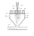
次に、熱風を用いた表面処理の方法の一態様を、図2を用いて説明するがこれに限定されない。
本発明では、表面にシリカ粒子Aを付着させた母体粒子に、熱風を用いた表面処理が施され、表面にシリカ粒子Aが固着された粒子をトナー粒子と呼ぶが、本明細書の説明においては、便宜上、表面にシリカ粒子Aが固着される前の粒子もトナー粒子と表現することがある。
図2は、本発明で用いた表面処理装置の断面図の一例である。表面処理の方法としては、具体的には、予め母体粒子の表面にシリカ粒子Aを付着させたものを原料とし、該原料を当該表面処理装置に供給する。
そして、トナー粒子供給口(100)から供給されたトナー粒子(114)は、高圧エア供給ノズル(115)から噴射されるインジェクションエアにより加速され、その下方にある気流噴射部材(102)へ向かう。
気流噴射部材(102)からは拡散エアが噴射され、この拡散エアによりトナー粒子が外側方向へ拡散する。この時、インジェクションエアの流量と拡散エアの流量とを調節することにより、トナー粒子の拡散状態をコントロールすることができる。
また、トナー粒子の融着防止を目的として、トナー粒子供給口(100)の外周、表面処理装置外周及び移送配管(116)の外周には冷却ジャケット(106)が設けられている。
尚、該冷却ジャケットには冷却水(好ましくはエチレングリコール等の不凍液)を通水することが好ましい。
一方、拡散エアにより拡散したトナー粒子は、熱風供給口(101)から供給された熱風により、トナー粒子の表面が処理される。
この時、熱風の吐出温度は100℃以上、300℃以下であることが好ましく、150℃以上、250℃以下であることがより好ましい。
熱風の温度が100℃未満の場合には、トナー粒子の溶融状態が不十分となり、トナー粒子の表面へのシリカ粒子Aの埋没が不十分となって、シリカ粒子Aを固着できない場合がある。
熱風の温度が300℃を超える場合にはトナー粒子の溶融状態が進みすぎてしまい、トナー粒子表面におけるシリカ粒子Aの埋没度合いが不均一となったり、トナー粒子の内部にシリカ粒子Aが完全に埋没したりしてしまい、得られるトナーの流動性や帯電性が悪化する場合がある。また、製造工程においてトナー粒子同士の合一が起こりやすくなり、トナー粒子が粗大化したり、装置内壁面へのトナー粒子の融着が酷くなったりする場合がある。
さらに、上記の温度範囲において熱風の吐出温度を調整することで、得られるトナーの平均円形度を0.955以上0.980以下に制御することができる。
高温で処理するほど、得られるトナーの平均円形度は高くなり、低温で処理するほど、得られるトナーの平均円形度は低くなることから、トナー粒子に加えられた熱量が多いほど、トナーの平均円形度は高くなる傾向にある。
そのためトナーの平均円形度によって、トナー粒子の表面におけるシリカ粒子Aの埋没する度合いが異なることが考えられる。しかし、本発明に用いられるシリカ粒子Aは、一次粒子の個数平均粒径(DA)が特定の範囲にあるため、トナーの平均円形度が上記の範囲において、トナー粒子の表面に適度に埋め込まれており、固着強度も高いため好ましい。
熱風により表面が処理されたトナー粒子は、装置上部外周に設けた冷風供給口(103)から供給される冷風により冷却される。この時、装置内の温度分布の制御、トナー粒子の表面状態をコントロールする目的で、装置の本体側面に設けた第二の冷風供給口(104)から冷風を導入することが好ましい。第二の冷風供給口(104)の出口はスリット形状、ルーバー形状、多孔板形状、メッシュ形状等を用いる事ができ、導入方向は中心方向へ水平、装置壁面に沿う方向が、目的に応じて選択可能である。
この時、上記冷風温度は−50℃以上、10℃以下であることが好ましく、−40℃以上、8℃以下であることがより好ましい。また、上記冷風は除湿空気であることが好ましい。具体的には、冷風中の絶対水分量が5g/m3以下であることが好ましい。更に好ましくは、3g/m3以下である。
これらの冷風温度が−50℃未満の場合には装置内の温度が下がりすぎてしまい、本来の目的である熱による処理が十分に為されず、トナー粒子の表面を溶融状態にすることができない場合がある。
また、10℃を超える場合には、熱風による表面処理が施されたトナー粒子を十分に冷却できず、トナー粒子同士の合一に起因するトナー粒子の粗大化や、融着が生じる場合がある。
その後、冷却されたトナー粒子は、ブロワーで吸引され、移送配管(116)を通じて、サイクロン等で回収される。
このようにして熱風による表面処理を施した後、必要に応じて分級機や篩分機を用いて分級し、表面にシリカ粒子Aが固着されたトナー粒子を得ることができる。
本発明のトナーは、熱風による表面処理を施した後のいずれかの段階で、さらに、一次粒子の個数平均粒径が5nm以上、50nm以下の、シリカ粒子及び酸化チタン粒子の少なくとも一方の粒子が外添されてなることがトナーの流動性をさらに改善する観点より好ましい。
Next, one embodiment of a surface treatment method using hot air will be described with reference to FIG. 2, but the present invention is not limited to this.
In the present invention, the base particles having the silica particles A attached to the surface are subjected to a surface treatment using hot air, and the particles having the silica particles A fixed on the surface are referred to as toner particles. For convenience, the particles before the silica particles A are fixed to the surface may also be expressed as toner particles.
FIG. 2 is an example of a cross-sectional view of the surface treatment apparatus used in the present invention. Specifically, as the surface treatment method, a material obtained by previously attaching the silica particles A to the surfaces of the base particles is used as a raw material, and the raw material is supplied to the surface treatment apparatus.
The toner particles (114) supplied from the toner particle supply port (100) are accelerated by the injection air injected from the high-pressure air supply nozzle (115) and travel toward the airflow injection member (102) below the injection air.
Diffusion air is ejected from the airflow ejecting member (102), and the toner particles are diffused outward by the diffusion air. At this time, the diffusion state of the toner particles can be controlled by adjusting the flow rate of the injection air and the flow rate of the diffusion air.
Further, for the purpose of preventing fusion of the toner particles, a cooling jacket (106) is provided on the outer periphery of the toner particle supply port (100), the outer periphery of the surface treatment apparatus, and the outer periphery of the transfer pipe (116).
In addition, it is preferable to pass cooling water (preferably antifreeze such as ethylene glycol) through the cooling jacket.
On the other hand, the toner particles diffused by the diffusion air are treated on the surface of the toner particles by the hot air supplied from the hot air supply port (101).
At this time, the hot air discharge temperature is preferably 100 ° C. or higher and 300 ° C. or lower, and more preferably 150 ° C. or higher and 250 ° C. or lower.
When the temperature of the hot air is less than 100 ° C., the melting state of the toner particles becomes insufficient, the silica particles A are not sufficiently embedded in the surface of the toner particles, and the silica particles A may not be fixed.
When the temperature of the hot air exceeds 300 ° C., the melting state of the toner particles progresses too much, the degree of embedding of the silica particles A on the toner particle surfaces becomes uneven, or the silica particles A are completely inside the toner particles. In some cases, the fluidity and chargeability of the resulting toner may be deteriorated. In addition, the toner particles are likely to coalesce in the manufacturing process, and the toner particles may be coarsened or the toner particles may be severely fused to the inner wall surface of the apparatus.
Further, the average circularity of the obtained toner can be controlled to 0.955 or more and 0.980 or less by adjusting the hot air discharge temperature in the above temperature range.
The higher the temperature, the higher the average circularity of the resulting toner, and the lower the temperature, the lower the average circularity of the resulting toner. The degree of circularity tends to increase.
Therefore, it can be considered that the degree of embedding of the silica particles A on the surface of the toner particles varies depending on the average circularity of the toner. However, since the number average particle diameter (D A ) of the primary particles is in a specific range, the silica particles A used in the present invention are appropriately embedded in the surface of the toner particles in the above range. It is preferable because of its high fixing strength.
The toner particles whose surface has been treated with hot air are cooled by cold air supplied from a cold air supply port (103) provided on the outer periphery of the upper part of the apparatus. At this time, it is preferable to introduce cold air from the second cold air supply port (104) provided on the side surface of the main body of the apparatus for the purpose of controlling the temperature distribution in the apparatus and controlling the surface state of the toner particles. The outlet of the second cold air supply port (104) can use a slit shape, a louver shape, a perforated plate shape, a mesh shape, etc., the introduction direction is horizontal to the center direction, and the direction along the apparatus wall surface depends on the purpose. Selectable.
At this time, the cold air temperature is preferably −50 ° C. or higher and 10 ° C. or lower, and more preferably −40 ° C. or higher and 8 ° C. or lower. The cold air is preferably dehumidified air. Specifically, the absolute water content in the cold air is preferably 5 g / m 3 or less. More preferably, it is 3 g / m 3 or less.
When the temperature of the cold air is less than -50 ° C., the temperature in the apparatus is too low, and the heat treatment that is the original purpose is not sufficiently performed, and the surface of the toner particles cannot be made into a molten state. There is a case.
When the temperature exceeds 10 ° C., the toner particles subjected to the surface treatment with hot air cannot be sufficiently cooled, and the toner particles may be coarsened or fused due to coalescence between the toner particles. .
Thereafter, the cooled toner particles are sucked by a blower and collected by a cyclone or the like through a transfer pipe (116).
After performing the surface treatment with hot air in this way, toner particles having silica particles A fixed on the surface can be obtained by classification using a classifier or a sieving machine as necessary.
In the toner of the present invention, at any stage after the surface treatment with hot air, the number average particle size of the primary particles is 5 nm or more and 50 nm or less, and at least one particle of silica particles and titanium oxide particles is present. External addition is preferable from the viewpoint of further improving the fluidity of the toner.
以下、本発明におけるトナー等の各種物性の測定法について説明する。
<固着されていない無機微粒子の分離方法>
本発明では、固着されている無機微粒子の測定を行う。
このため、以下の手法で固着されていない無機微粒子を取り除くことが必要である。
50ml容量のバイアルに「コンタミノンN」(非イオン界面活性剤、陰イオン界面活性剤、有機ビルダーからなるpH7の精密測定器洗浄用中性洗剤の2質量%水溶液20gを秤量し、トナー1gと混合する。いわき産業社製「KM Shaker」 (model: V.SX)にセットし、speedを50に設定して30秒間振とうする。その後、遠心分離機(1000rpmにて5分間)にて、トナーと水溶液を分離する。上澄み液を分離し、沈殿しているトナーを真空乾燥し、固着されていない無機微粒子を分離したトナー粒子を得た。
<トナー粒子表面に固着されているシリカ粒子Aの量>
本発明のトナー粒子100質量部に対するシリカ粒子Aの添加量[質量部]は、蛍光X線分析装置で求めることができる。以下本発明における測定方法を説明する。
波長分散型蛍光X線分析装置Axios advanced(PANalytical社製)を用いてHe雰囲気下、FP法にてトナー粒子中のSi元素を直接測定する。
本発明では、実施例中に示したトナー粒子1の製造例のうち、シリカ粒子A−1の添加量を1.0質量部、2.0質量部、5.0質量部、10.0質量部と変えて、標品を作成した。それぞれのSi元素量を測定し、シリカに対する検量線を作成する。
その後、固着されていない無機微粒子を分離したトナー粒子を該波長分散型蛍光X線分析装置で測定し、得られた蛍光X線強度を、検量線と比較し、シリカ粒子Aの添加量[質量部](上述の[C])を算出した。
<X線光電子分光分析(ESCA)による表面組成分析>
本発明において、トナー粒子表面のシリカ粒子Aによる被覆率(すなわち、[B])は、X線光電子分光分析(ESCA)による表面組成分析を行い算出される。ESCAの装置及び測定条件は、下記の通りである。
使用装置:PHI社(Physical Electronics Industries, INC.)製、Quantum 2000 Scanning ESCA Microprobe
測定条件:
X線源 ;AlKα(100μ25W15KV)
Angle ;45°
Pass Energy;58.70eV
測定試料としては、固着されていない無機微粒子を分離したトナー粒子を用いる。
以上の条件により測定された各元素のピーク強度から、PHI社提供の相対感度因子を用いて表面原子濃度(原子%)を算出する。
測定元素としては、C、O、Si、Ti、Al、Ca、Srの7種類を測定し、これら7種類の元素中のSiの割合を算出する。各々の原子に関して、C:1s、O:1s、Si:2p、Ti:2p軌道、Al:2p軌道、Ca:2p軌道、Sr:3d軌道に基づくピーク強度を参照する。
シリカ(SiO2)におけるSiの元素濃度は33%であるため、上記で得られたSi
濃度(原子%)の3倍をシリカ粒子の濃度と考え、この値をもって被覆率[B]とした。尚、上記の7種類の元素は、トナー粒子表面に存在する元素、或いは、外添剤を構成する代表的な元素である。
Hereinafter, methods for measuring various physical properties of the toner and the like in the present invention will be described.
<Method for separating inorganic fine particles not fixed>
In the present invention, the fixed inorganic fine particles are measured.
For this reason, it is necessary to remove the inorganic fine particles not fixed by the following method.
In a 50 ml vial, weigh 20 g of a 2% by weight aqueous solution of “Contaminone N” (neutral detergent, anionic surfactant, neutral detergent for pH 7 precision measuring instrument washing comprising an organic builder and 1 g of toner. Set to “KM Shaker” (model: V.SX) manufactured by Iwaki Sangyo Co., Ltd., set speed to 50 and shake for 30 seconds, then centrifuge (1000 rpm for 5 minutes), The toner and the aqueous solution are separated, the supernatant liquid is separated, and the precipitated toner is vacuum-dried to obtain toner particles from which inorganic fine particles not fixed are separated.
<Amount of silica particles A fixed to the toner particle surface>
The addition amount [parts by mass] of the silica particles A with respect to 100 parts by mass of the toner particles of the present invention can be determined with a fluorescent X-ray analyzer. The measurement method in the present invention will be described below.
The Si element in the toner particles is directly measured by the FP method in a He atmosphere using a wavelength dispersive X-ray fluorescence analyzer Axios advanced (manufactured by PANalytical).
In the present invention, among the production examples of the toner particles 1 shown in Examples, the addition amount of silica particles A-1 is 1.0 part by mass, 2.0 parts by mass, 5.0 parts by mass, 10.0 parts by mass. A standard was created instead of the part. The amount of each Si element is measured, and a calibration curve for silica is created.
Thereafter, the toner particles from which the inorganic fine particles that are not fixed are separated are measured with the wavelength dispersion type fluorescent X-ray analyzer, and the obtained fluorescent X-ray intensity is compared with a calibration curve, and the added amount of silica particles A [mass Part] (the above-mentioned [C]).
<Surface composition analysis by X-ray photoelectron spectroscopy (ESCA)>
In the present invention, the coverage of the toner particle surface with silica particles A (ie, [B]) is calculated by performing a surface composition analysis by X-ray photoelectron spectroscopy (ESCA). The ESCA apparatus and measurement conditions are as follows.
Equipment used: Quantum 2000 Scanning ESCA Microprobe, manufactured by PHI (Physical Electronics Industries, Inc.)
Measurement condition:
X-ray source: AlKα (100μ25W15KV)
Angle; 45 °
Pass Energy; 58.70 eV
As a measurement sample, toner particles obtained by separating inorganic fine particles that are not fixed are used.
From the peak intensity of each element measured under the above conditions, the surface atomic concentration (atomic%) is calculated using a relative sensitivity factor provided by PHI.
As measurement elements, seven types of C, O, Si, Ti, Al, Ca, and Sr are measured, and the ratio of Si in these seven types of elements is calculated. For each atom, reference is made to the peak intensities based on C: 1s, O: 1s, Si: 2p, Ti: 2p orbital, Al: 2p orbital, Ca: 2p orbital, and Sr: 3d orbital.
Since the element concentration of Si in silica (SiO 2 ) is 33%, the Si obtained above
Three times the concentration (atomic%) was considered as the concentration of silica particles, and this value was defined as the coverage [B]. The above seven types of elements are elements present on the surface of the toner particles or representative elements constituting the external additive.
<シリカ粒子A及びその他の無機微粒子の一次粒子の個数平均粒径の測定方法>
シリカ粒子A等の一次粒子の個数平均粒径の測定は、電界放射型走査電子顕微鏡(FE−SEM)S−4700(日立製作所製)を用いて行う。
撮影倍率は5万倍とし、撮影された写真をさらに2倍に引き伸ばした後、得られたFE−SEM写真像から、トナー粒子表面の固着されたシリカ粒子A等(一次粒子)露出している面の最大径(長軸径)Laを測定する。同時に露出面の高さLbを算出する。
LaとLbから、シリカ粒子の最大径は(La2/4+Lb2)/Lbと算出される。ランダムに選択した100個のシリカ粒子A等(一次粒子)について同様の計算を行い、シリカ粒子A等(一次粒子)の個数平均粒径とする。
<Method for Measuring Number Average Particle Size of Primary Particles of Silica Particles A and Other Inorganic Fine Particles>
The number average particle diameter of primary particles such as silica particles A is measured using a field emission scanning electron microscope (FE-SEM) S-4700 (manufactured by Hitachi, Ltd.).
The photographing magnification is set to 50,000 times, and after the photographed photograph is further doubled, the silica particles A and the like (primary particles) to which the toner particle surface is adhered are exposed from the obtained FE-SEM photograph image. The maximum diameter (major axis diameter) La of the surface is measured. At the same time, the height Lb of the exposed surface is calculated.
From La and Lb, the maximum diameter of the silica particles is calculated as (La 2/4 + Lb 2 ) / Lb. The same calculation is performed on 100 randomly selected silica particles A and the like (primary particles) to obtain the number average particle diameter of the silica particles A and the like (primary particles).
<シリカ粒子AのBET比表面積(BETA)の測定方法>
シリカ粒子AのBET比表面積(BETA)の測定は、JIS Z8830(2001年)に準じて行った。
具体的な測定方法は、以下の通りである。
測定装置としては、定容法によるガス吸着法を測定方式として採用している「自動比表面積・細孔分布測定装置 TriStar3000(島津製作所社製)」を用いた。
測定条件の設定および測定データの解析は、本装置に付属の専用ソフト「TriStar3000 Version4.00」を用いて行い、また装置には真空ポンプ、窒素ガス配管、ヘリウムガス配管を接続した。窒素ガスを吸着ガスとして用い、BET多点法により算出した値を本発明におけるBET比表面積とした。
BET比表面積は、具体的には以下のようにして算出する。
まず、シリカ粒子Aに窒素ガスを吸着させ、その時の試料セル内の平衡圧力P(Pa)とシリカ粒子Aの窒素吸着量Va(モル・g−1)を測定する。そして、試料セル内の平衡圧力P(Pa)を窒素の飽和蒸気圧Po(Pa)で除した値である相対圧Prを横軸とし、窒素吸着量Va(モル・g−1)を縦軸とした吸着等温線を得る。次いで、シリカ粒子Aの表面に単分子層を形成するのに必要な吸着量である単分子層吸着量Vm(モル・g−1)を、下記のBET式を適用して求める。
Pr/Va(1−Pr)=1/(Vm×C)+(C−1)×Pr/(Vm×C)
(ここで、CはBETパラメーターであり、測定サンプル種、吸着ガス種、吸着温度により変動する変数である。)
BET式は、X軸をPr、Y軸をPr/Va(1−Pr)とすると、傾きが(C−1)/(Vm×C)、切片が1/(Vm×C)の直線と解釈できる(この直線をBETプロットという)。
直線の傾き=(C−1)/(Vm×C)
直線の切片=1/(Vm×C)
Prの実測値とPr/Va(1−Pr)の実測値をグラフ上にプロットして最小二乗法により直線を引くと、その直線の傾きと切片の値が算出できる。これらの値を用いて上記の傾きと切片の連立方程式を解くと、VmとCが算出できる。
さらに、上記で算出したVmと窒素分子の分子占有断面積(0.162nm2)から、下記の式に基づいて、シリカ粒子AのBET比表面積S(m2・g−1)を算出する。
S=Vm×N×0.162×10⁻¹⁸
(ここで、Nはアボガドロ数(モル−1)である。)
本装置を用いた測定は、装置に付属の「TriStar3000 取扱説明書V4.0」に従うが、具体的には、以下の手順で測定する。
充分に洗浄、乾燥した専用のガラス製試料セル(ステム直径3/8インチ、容積約5ml)の風袋を精秤する。そして、ロートを使ってこの試料セルの中に0.3gのシリカ粒
子Aを入れる。
シリカ粒子Aを入れた前記試料セルを真空ポンプと窒素ガス配管を接続した「前処理装置 バキュプレップ061(島津製作所社製)」にセットし、23℃にて真空脱気を約10時間継続して行なう。尚、真空脱気の際には、シリカ粒子Aが真空ポンプに吸引されないよう、バルブを調整しながら徐々に脱気する。セル内の圧力は脱気とともに徐々に下がり、最終的には約0.4Pa(約3ミリトール)となる。真空脱気終了後、窒素ガスを徐々に注入して試料セル内を大気圧に戻し、試料セルを前処理装置から取り外す。そして、この試料セルの質量を精秤し、風袋との差からシリカ粒子Aの正確な質量を算出する。尚、この際に、試料セル内のシリカ粒子Aが大気中の水分等で汚染されないように、秤量中はゴム栓で試料セルに蓋をしておく。
次に、シリカ粒子Aが入った前記試料セルのステム部に専用の「等温ジャケット」を取り付ける。そして、この試料セル内に専用のフィラーロッドを挿入し、前記装置の分析ポートに試料セルをセットする。尚、等温ジャケットとは、毛細管現象により液体窒素を一定レベルまで吸い上げることが可能な、内面が多孔性材料、外面が不浸透性材料で構成された筒状の部材である。
続いて、接続器具を含む試料セルのフリースペースの測定を行なう。フリースペースは、23℃においてヘリウムガスを用いて試料セルの容積を測定し、続いて液体窒素で試料セルを冷却した後の試料セルの容積を、同様にヘリウムガスを用いて測定して、これらの容積の差から換算して算出する。また、窒素の飽和蒸気圧Po(Pa)は、装置に内蔵されたPoチューブを使用して、別途に自動で測定される。
次に、試料セル内の真空脱気を行った後、真空脱気を継続して行ないながら試料セルを液体窒素で冷却する。その後、窒素ガスを試料セル内に段階的に導入してシリカ粒子Aに窒素分子を吸着させる。この際、平衡圧力P(Pa)を随時計測することにより前記した吸着等温線が得られるので、この吸着等温線をBETプロットに変換する。尚、データを収集する相対圧Prのポイントは、0.05、0.10、0.15、0.20、0.25、0.30の合計6ポイントに設定する。得られた測定データに対して最小二乗法により直線を引き、その直線の傾きと切片からVmを算出する。さらに、このVmの値を用いて、前記したようにシリカ粒子AのBET比表面積を算出する。
<Method for Measuring BET Specific Surface Area (BET A ) of Silica Particle A>
The BET specific surface area (BET A ) of the silica particles A was measured according to JIS Z8830 (2001).
A specific measurement method is as follows.
As a measuring device, an “automatic specific surface area / pore distribution measuring device TriStar 3000 (manufactured by Shimadzu Corporation)” which employs a gas adsorption method by a constant volume method as a measuring method was used.
Setting of measurement conditions and analysis of measurement data were performed using dedicated software “TriStar3000 Version 4.00” attached to the apparatus, and a vacuum pump, nitrogen gas pipe, and helium gas pipe were connected to the apparatus. The value calculated by the BET multipoint method using nitrogen gas as the adsorption gas was defined as the BET specific surface area in the present invention.
Specifically, the BET specific surface area is calculated as follows.
First, nitrogen gas is adsorbed on the silica particles A, and the equilibrium pressure P (Pa) in the sample cell and the nitrogen adsorption amount Va (mol · g −1 ) of the silica particles A at that time are measured. The relative pressure Pr, which is a value obtained by dividing the equilibrium pressure P (Pa) in the sample cell by the saturated vapor pressure Po (Pa) of nitrogen, is plotted on the horizontal axis, and the nitrogen adsorption amount Va (mol · g −1 ) is plotted on the vertical axis. The adsorption isotherm is obtained. Next, a monomolecular layer adsorption amount Vm (mol · g −1 ), which is an adsorption amount necessary for forming a monomolecular layer on the surface of the silica particle A, is obtained by applying the following BET equation.
Pr / Va (1-Pr) = 1 / (Vm * C) + (C-1) * Pr / (Vm * C)
(Here, C is a BET parameter, which is a variable that varies depending on the measurement sample type, adsorbed gas type, and adsorption temperature.)
The BET equation is interpreted as a straight line with an inclination of (C-1) / (Vm × C) and an intercept of 1 / (Vm × C), where Pr is X axis and Pr / Va (1-Pr) is Y axis. Yes (this line is called a BET plot).
Straight line slope = (C-1) / (Vm × C)
Straight line intercept = 1 / (Vm × C)
When the measured value of Pr and the measured value of Pr / Va (1-Pr) are plotted on a graph and a straight line is drawn by the least square method, the slope and intercept value of the straight line can be calculated. Vm and C can be calculated by solving the above slope and intercept simultaneous equations using these values.
Furthermore, the BET specific surface area S (m 2 · g −1 ) of the silica particles A is calculated from the Vm calculated above and the molecular occupation cross-sectional area (0.162 nm 2 ) of nitrogen molecules based on the following formula.
S = Vm × N × 0.162 × 10 −18
(N is Avogadro's number (mol- 1 ).)
The measurement using this apparatus follows the “TriStar 3000 Instruction Manual V4.0” attached to the apparatus, and specifically, the measurement is performed according to the following procedure.
Thoroughly weigh the tare of a dedicated glass sample cell (stem diameter 3/8 inch, volume about 5 ml) that has been thoroughly cleaned and dried. Then, 0.3 g of silica particles A are put into the sample cell using a funnel.
The sample cell containing the silica particles A is set in a “pretreatment device Bacrepprep 061 (manufactured by Shimadzu Corporation)” connected with a vacuum pump and a nitrogen gas pipe, and vacuum degassing is continued at 23 ° C. for about 10 hours. Do it. During vacuum deaeration, the silica particles A are gradually deaerated while adjusting the valve so that the silica particles A are not sucked into the vacuum pump. The pressure in the cell gradually decreases with deaeration and finally becomes about 0.4 Pa (about 3 mTorr). After completion of vacuum degassing, nitrogen gas is gradually injected to return the inside of the sample cell to atmospheric pressure, and the sample cell is removed from the pretreatment device. Then, the mass of the sample cell is precisely weighed, and the exact mass of the silica particles A is calculated from the difference from the tare. At this time, the sample cell is covered with a rubber plug during weighing so that the silica particles A in the sample cell are not contaminated by moisture in the atmosphere.
Next, a dedicated “isothermal jacket” is attached to the stem portion of the sample cell containing the silica particles A. Then, a dedicated filler rod is inserted into the sample cell, and the sample cell is set in the analysis port of the apparatus. The isothermal jacket is a cylindrical member having an inner surface made of a porous material and an outer surface made of an impermeable material capable of sucking liquid nitrogen to a certain level by capillary action.
Subsequently, the free space of the sample cell including the connection tool is measured. The free space is measured by measuring the volume of the sample cell using helium gas at 23 ° C., and then measuring the volume of the sample cell after cooling the sample cell with liquid nitrogen using helium gas. It is calculated by converting from the difference in volume. The saturated vapor pressure Po (Pa) of nitrogen is automatically measured separately using a Po tube built in the apparatus.
Next, after vacuum deaeration in the sample cell, the sample cell is cooled with liquid nitrogen while the vacuum deaeration is continued. Thereafter, nitrogen gas is gradually introduced into the sample cell to adsorb nitrogen molecules on the silica particles A. At this time, the adsorption isotherm is obtained by measuring the equilibrium pressure P (Pa) as needed, and the adsorption isotherm is converted into a BET plot. Note that the points of the relative pressure Pr for collecting data are set to a total of 6 points of 0.05, 0.10, 0.15, 0.20, 0.25, and 0.30. A straight line is drawn from the obtained measurement data by the least square method, and Vm is calculated from the slope and intercept of the straight line. Further, using the value of Vm, the BET specific surface area of the silica particles A is calculated as described above.
<シリカ粒子A及びトナーの真密度の測定方法>
乾式自動密度計アキュピック1330(島津製作所社製)を用いて測定した。
まず、温度23℃湿度50%RHの環境に24時間放置したサンプル試料を5g秤量し、測定用セル(10cm3)に入れ、本体試料室に挿入する。測定は、測定試料サンプル質量を本体に入力し、測定をスタートさせることにより自動測定できる。
自動測定の測定条件は、2.392×10²kPaで調整されたヘリウムガスを用い、試料室内にパージした後、試料室内の圧力変化が3.447×10⁻²kPa/分になる状態を平衡状態とし、平衡状態になるまで繰り返しヘリウムガスをパージする。
平衡状態時の本体試料室の圧力を測定し、その状態に達したときの圧力変化により試料サンプル体積が算出できる(ボイルの法則)。
試料サンプルの体積が算出し、以下の式で試料サンプルの真密度を計算した。
真密度(g/cm3)=試料サンプル質量(g)/試料サンプル体積(cm3)
この自動測定により5回繰り返した測定値の平均値をサンプル試料の真密度(g/cm3)とした。
<Method for Measuring True Density of Silica Particle A and Toner>
Measurement was performed using a dry automatic densimeter AccuPick 1330 (manufactured by Shimadzu Corporation).
First, 5 g of a sample sample left in an environment of a temperature of 23 ° C. and a humidity of 50% RH for 24 hours is weighed, placed in a measurement cell (10 cm 3 ), and inserted into the main body sample chamber. The measurement can be automatically performed by inputting the measurement sample sample mass into the main body and starting the measurement.
The measurement conditions for automatic measurement are as follows: after purging the sample chamber with helium gas adjusted at 2.392 × 10 2 kPa, the pressure change in the sample chamber becomes 3.447 × 10 −2 kPa / min. Equilibrate and purge with helium gas repeatedly until equilibrium is reached.
The pressure in the main body sample chamber in the equilibrium state can be measured, and the sample sample volume can be calculated from the pressure change when that state is reached (Boil's law).
The volume of the sample sample was calculated, and the true density of the sample sample was calculated using the following formula.
True density (g / cm 3 ) = sample sample mass (g) / sample sample volume (cm 3 )
The average value of the measurement values repeated five times by this automatic measurement was taken as the true density (g / cm 3 ) of the sample specimen.
<トナーの平均円形度の算出方法>
トナーの平均円形度は、フロー式粒子像分析装置「FPIA−3000」(シスメックス社製)によって、校正作業時の測定及び解析条件で測定する。
フロー式粒子像分析装置「FPIA−3000」(シスメックス社製)の測定原理は、流れている粒子を静止画像として撮像し、画像解析を行うというものである。試料チャンバーへ加えられた試料は、試料吸引シリンジによって、フラットシースフローセルに送り
込まれる。フラットシースフローに送り込まれた試料は、シース液に挟まれて扁平な流れを形成する。フラットシースフローセル内を通過する試料に対しては、1/60秒間隔でストロボ光が照射されており、流れている粒子を静止画像として撮影することが可能である。また、扁平な流れであるため、焦点の合った状態で撮像される。粒子像はCCDカメラで撮像され、撮像された画像は512×512画素の画像処理解像度(一画素あたり0.37×0.37μm)で画像処理され、各粒子像の輪郭抽出を行い、粒子像の投影面積Sや周囲長L等が計測される。
次に、上記面積Sと周囲長Lを用いて円相当径と円形度を求める。円相当径とは、粒子像の投影面積と同じ面積を持つ円の直径のことであり、円形度Cは、円相当径から求めた円の周囲長を粒子投影像の周囲長で割った値として定義され、次式で算出される。
円形度C=2×(π×S)1/2/L
粒子像が円形の時に円形度は1.000になり、粒子像外周の凹凸の程度が大きくなればなるほど円形度は小さい値になる。各粒子の円形度を算出後、円形度0.200乃至1.000の範囲を800分割し、得られた円形度の相加平均値を算出し、その値を平均円形度とする。
具体的な測定方法は、以下の通りである。まず、ガラス製の容器中に予め不純固形物などを除去したイオン交換水20mlを入れる。この中に分散剤として「コンタミノンN」(非イオン界面活性剤、陰イオン界面活性剤、有機ビルダーからなるpH7の精密測定器洗浄用中性洗剤の10質量%水溶液、和光純薬工業社製)をイオン交換水で3質量倍に希釈した希釈液を0.2ml加える。更に測定試料を0.02g加え、超音波分散器を用いて2分間分散処理を行い、測定用の分散液とする。その際、分散液の温度が10℃以上40℃以下となる様に適宜冷却する。超音波分散器としては、発振周波数50kHz、電気的出力150Wの卓上型の超音波洗浄器分散器(例えば「VS−150」(ヴェルヴォクリーア社製))を用い、水槽内には所定量のイオン交換水を入れ、この水槽中に該コンタミノンNを2ml添加する。
測定には、標準対物レンズ(10倍)を搭載した該フロー式粒子像分析装置を用い、シース液にはパーティクルシース「PSE−900A」(シスメックス社製)を使用する。該手順に従い調製した分散液を該フロー式粒子像分析装置に導入し、HPF測定モードで、トータルカウントモードにて3000個のトナー粒子を計測する。そして、粒子解析時の2値化閾値を85%とし、解析粒子径を円相当径1.985μm以上、39.69μm未満に限定し、トナー粒子の平均円形度を求める。
測定にあたっては、測定開始前に標準ラテックス粒子(例えば、Duke Scientific社製の「RESEARCH AND TEST PARTICLES Latex Microsphere Suspensions 5200A」をイオン交換水で希釈)を用いて自動焦点調整を行う。その後、測定開始から2時間毎に焦点調整を実施することが好ましい。
なお、本願実施例では、シスメックス社による校正作業が行われた、シスメックス社が発行する校正証明書の発行を受けたフロー式粒子像分析装置を使用する。解析粒子径を円相当径1.985μm以上、39.69μm未満に限定した以外は、校正証明を受けた時の測定及び解析条件で測定を行う。
<Calculation method of average circularity of toner>
The average circularity of the toner is measured by a flow type particle image analyzer “FPIA-3000” (manufactured by Sysmex Corporation) under the measurement and analysis conditions during the calibration operation.
The measurement principle of the flow-type particle image analyzer “FPIA-3000” (manufactured by Sysmex Corporation) is to capture flowing particles as a still image and perform image analysis. The sample added to the sample chamber is fed into the flat sheath flow cell by a sample suction syringe. The sample fed into the flat sheath flow is sandwiched between sheath liquids to form a flat flow. The sample passing through the flat sheath flow cell is irradiated with strobe light at 1/60 second intervals, and the flowing particles can be photographed as a still image. Further, since the flow is flat, the image is taken in a focused state. The particle image is picked up by a CCD camera, and the picked-up image is image-processed at an image processing resolution of 512 × 512 pixels (0.37 × 0.37 μm per pixel), the contour of each particle image is extracted, and the particle image The projected area S, the peripheral length L, etc. are measured.
Next, the equivalent circle diameter and the circularity are obtained using the area S and the peripheral length L. The equivalent circle diameter is the diameter of a circle having the same area as the projected area of the particle image, and the circularity C is a value obtained by dividing the circumference of the circle obtained from the equivalent circle diameter by the circumference of the projected particle image. And is calculated by the following formula.
Circularity C = 2 × (π × S) 1/2 / L
When the particle image is circular, the circularity is 1.000, and the greater the degree of unevenness around the particle image, the smaller the circularity. After calculating the circularity of each particle, the range of the circularity of 0.200 to 1.000 is divided into 800, the arithmetic average value of the obtained circularity is calculated, and the value is defined as the average circularity.
A specific measurement method is as follows. First, 20 ml of ion-exchanged water from which impure solids and the like have been removed in advance is placed in a glass container. In this, "Contaminone N" (nonionic surfactant, anionic surfactant, 10% by weight aqueous solution of neutral detergent for pH7 precision measuring instrument cleaning, made by organic builder, manufactured by Wako Pure Chemical Industries, Ltd. 0.2 ml of a diluted solution obtained by diluting 3) times with ion-exchanged water. Further, 0.02 g of a measurement sample is added, and a dispersion treatment is performed for 2 minutes using an ultrasonic disperser to obtain a dispersion for measurement. In that case, it cools suitably so that the temperature of a dispersion liquid may become 10 to 40 degreeC. As the ultrasonic disperser, a desktop ultrasonic cleaner disperser (for example, “VS-150” (manufactured by Velvo Crea)) having an oscillation frequency of 50 kHz and an electric output of 150 W is used. Ion exchanged water is added, and 2 ml of the contamination N is added to the water tank.
For the measurement, the flow type particle image analyzer equipped with a standard objective lens (10 ×) is used, and the particle sheath “PSE-900A” (manufactured by Sysmex Corporation) is used as the sheath liquid. The dispersion prepared in accordance with the procedure is introduced into the flow particle image analyzer, and 3000 toner particles are measured in the total count mode in the HPF measurement mode. Then, the binarization threshold at the time of particle analysis is set to 85%, the analysis particle diameter is limited to the circle equivalent diameter of 1.985 μm or more and less than 39.69 μm, and the average circularity of the toner particles is obtained.
In the measurement, automatic focus adjustment is performed using standard latex particles (eg, “RESEARCH AND TEST PARTICLES Latex Microsphere Suspensions 5200A” manufactured by Duke Scientific) diluted with ion-exchanged water before starting the measurement. Thereafter, it is preferable to perform focus adjustment every two hours from the start of measurement.
In the embodiment of the present application, a flow type particle image analyzer which has been issued a calibration certificate issued by Sysmex Corporation, which has been calibrated by Sysmex Corporation, is used. Measurement is performed under the measurement and analysis conditions when the calibration certificate is received, except that the analysis particle diameter is limited to a circle equivalent diameter of 1.985 μm or more and less than 39.69 μm.
<トナーの重量平均粒径(D4)の測定方法>
トナーの重量平均粒径(D4)は、以下のようにして算出する。測定装置としては、100μmのアパーチャーチューブを備えた細孔電気抵抗法による精密粒度分布測定装置「コールター・カウンター Multisizer 3」(登録商標、ベックマン・コールター社製)を用いる。測定条件の設定及び測定データの解析は、付属の専用ソフト「ベックマン・コールター Multisizer 3 Version3.51」(ベックマン・コールター社製)を用いる。尚、測定は実効測定チャンネル数2万5千チャンネルで行う。
測定に使用する電解水溶液は、特級塩化ナトリウムをイオン交換水に溶解して濃度が1
質量%となるようにしたもの、例えば、「ISOTON II」(ベックマン・コールター社製)が使用できる。
尚、測定、解析を行う前に、以下のように専用ソフトの設定を行う。
専用ソフトの「標準測定方法(SOM)を変更」画面において、コントロールモードの総カウント数を50000粒子に設定し、測定回数を1回、Kd値は「標準粒子10.0μm」(ベックマン・コールター社製)を用いて得られた値を設定する。「閾値/ノイズレベルの測定ボタン」を押すことで、閾値とノイズレベルを自動設定する。また、カレントを1600μAに、ゲインを2に、電解液をISOTON IIに設定し、「測定後のアパーチャーチューブのフラッシュ」にチェックを入れる。
専用ソフトの「パルスから粒径への変換設定」画面において、ビン間隔を対数粒径に、粒径ビンを256粒径ビンに、粒径範囲を2μmから60μmまでに設定する。
具体的な測定法は以下の通りである。
(1)Multisizer 3専用のガラス製250ml丸底ビーカーに該電解水溶液200mlを入れ、サンプルスタンドにセットし、スターラーロッドの撹拌を反時計回りで24回転/秒にて行う。そして、専用ソフトの「アパーチャーのフラッシュ」機能により、アパーチャーチューブ内の汚れと気泡を除去しておく。
(2)ガラス製の100ml平底ビーカーに該電解水溶液30mlを入れる。この中に分散剤として「コンタミノンN」(非イオン界面活性剤、陰イオン界面活性剤、有機ビルダーからなるpH7の精密測定器洗浄用中性洗剤の10質量%水溶液、和光純薬工業社製)をイオン交換水で3質量倍に希釈した希釈液を0.3ml加える。
(3)発振周波数50kHzの発振器2個を、位相を180度ずらした状態で内蔵し、電気的出力120Wの超音波分散器「Ultrasonic Dispersion System Tetora150」(日科機バイオス社製)を準備する。超音波分散器の水槽内に3.3lのイオン交換水を入れ、この水槽中にコンタミノンNを2ml添加する。(4)該(2)のビーカーを該超音波分散器のビーカー固定穴にセットし、超音波分散器を作動させる。そして、ビーカー内の電解水溶液液面の共振状態が最大となるようにビーカーの高さ位置を調整する。
(5)該(4)のビーカー内の電解水溶液に超音波を照射した状態で、トナー10mgを少量ずつ該電解水溶液に添加し、分散させる。そして、さらに60秒間超音波分散処理を継続する。尚、超音波分散にあたっては、水槽の水温が10℃以上40℃以下となる様に適宜調節する。
(6)サンプルスタンド内に設置した該(1)の丸底ビーカーに、ピペットを用いてトナーを分散した該(5)の電解質水溶液を滴下し、測定濃度が5%となるように調整する。そして、測定粒子数が50000個になるまで測定を行う。
(7)測定データを装置付属の該専用ソフトにて解析を行い、重量平均粒径(D4)を算出する。尚、専用ソフトでグラフ/体積%と設定したときの、「分析/体積統計値(算術平均)」画面の「平均径」が重量平均粒径(D4)である。
<Method for Measuring Toner Weight Average Particle Size (D4)>
The weight average particle diameter (D4) of the toner is calculated as follows. As a measuring device, a precise particle size distribution measuring device “Coulter Counter Multisizer 3” (registered trademark, manufactured by Beckman Coulter, Inc.) using a pore electrical resistance method equipped with a 100 μm aperture tube is used. For setting the measurement conditions and analyzing the measurement data, the attached dedicated software “Beckman Coulter Multisizer 3 Version 3.51” (manufactured by Beckman Coulter, Inc.) is used. The measurement is performed with 25,000 effective measurement channels.
The electrolytic aqueous solution used for the measurement has a concentration of 1 by dissolving special grade sodium chloride in ion exchange water.
For example, “ISOTON II” (manufactured by Beckman Coulter, Inc.) can be used.
Prior to measurement and analysis, the dedicated software is set as follows.
On the “Change Standard Measurement Method (SOM)” screen of the dedicated software, set the total count in the control mode to 50000 particles, set the number of measurements once, and set the Kd value to “standard particles 10.0 μm” (Beckman Coulter, Inc.) Set the value obtained using By pressing the “Threshold / Noise Level Measurement Button”, the threshold and noise level are automatically set. In addition, the current is set to 1600 μA, the gain is set to 2, the electrolyte is set to ISOTON II, and the “aperture tube flush after measurement” is checked.
In the “Pulse to particle size conversion setting” screen of the dedicated software, the bin interval is set to logarithmic particle size, the particle size bin is set to 256 particle size bin, and the particle size range is set to 2 μm to 60 μm.
The specific measurement method is as follows.
(1) Put 200 ml of the aqueous electrolytic solution into a glass 250 ml round bottom beaker for exclusive use of Multisizer 3, set it on a sample stand, and stir the stirrer rod counterclockwise at 24 rpm. Then, the dirt and bubbles in the aperture tube are removed by the “aperture flush” function of the dedicated software.
(2) 30 ml of the electrolytic aqueous solution is placed in a
(3) Two oscillators with an oscillation frequency of 50 kHz are incorporated with the phase shifted by 180 degrees, and an ultrasonic disperser “Ultrasonic Dispersion System Tetora 150” (manufactured by Nikka Ki Bios) having an electrical output of 120 W is prepared. Into the water tank of the ultrasonic disperser, 3.3 l of ion-exchanged water is added, and 2 ml of Contaminone N is added to the water tank. (4) The beaker of (2) is set in the beaker fixing hole of the ultrasonic disperser, and the ultrasonic disperser is operated. And the height position of a beaker is adjusted so that the resonance state of the electrolyte solution liquid surface in a beaker may become the maximum.
(5) In a state where the electrolytic aqueous solution in the beaker of (4) is irradiated with ultrasonic waves, 10 mg of toner is added to the electrolytic aqueous solution little by little and dispersed. Then, the ultrasonic dispersion process is continued for another 60 seconds. In the ultrasonic dispersion, the temperature of the water tank is appropriately adjusted so as to be 10 ° C. or higher and 40 ° C. or lower.
(6) To the round bottom beaker of (1) installed in a sample stand, the electrolyte aqueous solution of (5) in which toner is dispersed is dropped using a pipette, and the measured concentration is adjusted to 5%. Measurement is performed until the number of measured particles reaches 50,000.
(7) The measurement data is analyzed with the dedicated software attached to the apparatus, and the weight average particle diameter (D4) is calculated. The “average diameter” on the “analysis / volume statistics (arithmetic average)” screen when the graph / volume% is set in the dedicated software is the weight average particle diameter (D4).
<樹脂のピーク分子量(Mp)、数平均分子量(Mn)、重量平均分子量(Mw)の測定方法>
樹脂のピーク分子量(Mp)、数平均分子量(Mn)、重量平均分子量(Mw)は、ゲルパーミエーションクロマトグラフィー(GPC)により、以下のようにして測定する。
まず、室温で24時間かけて、試料をテトラヒドロフラン(THF)に溶解する。そして、得られた溶液を、ポア径が0.2μmの耐溶剤性メンブランフィルター「マエショリディスク」(東ソー社製)で濾過してサンプル溶液を得る。尚、サンプル溶液は、THFに可溶な成分の濃度が0.8質量%となるように調整する。このサンプル溶液を用いて、以下の条件で測定する。
装置 :HLC8120 GPC(検出器:RI)(東ソー社製)
カラム :Shodex KF−801、802、803、804、805、
806、807の7連(昭和電工社製)
溶離液 :テトラヒドロフラン(THF)
流速 :1.0ml/min
オーブン温度 :40.0℃
試料注入量 :0.10ml
試料の分子量の算出にあたっては、標準ポリスチレン樹脂(例えば、商品名「TSKスタンダード ポリスチレン F−850、F−450、F−288、F−128、F−80、F−40、F−20、F−10、F−4、F−2、F−1、A−5000、A−2500、A−1000、A−500」、東ソ−社製)を用いて作成した分子量校正曲線を使用する。
<Measurement method of resin peak molecular weight (Mp), number average molecular weight (Mn), weight average molecular weight (Mw)>
The peak molecular weight (Mp), number average molecular weight (Mn), and weight average molecular weight (Mw) of the resin are measured by gel permeation chromatography (GPC) as follows.
First, a sample is dissolved in tetrahydrofuran (THF) at room temperature over 24 hours. The obtained solution is filtered through a solvent-resistant membrane filter “Maescho Disc” (manufactured by Tosoh Corporation) having a pore diameter of 0.2 μm to obtain a sample solution. The sample solution is adjusted so that the concentration of the component soluble in THF is 0.8% by mass. Using this sample solution, measurement is performed under the following conditions.
Apparatus: HLC8120 GPC (detector: RI) (manufactured by Tosoh Corporation)
Column: Shodex KF-801, 802, 803, 804, 805,
7 series of 806, 807 (made by Showa Denko)
Eluent: Tetrahydrofuran (THF)
Flow rate: 1.0 ml / min
Oven temperature: 40.0 ° C
Sample injection volume: 0.10 ml
In calculating the molecular weight of the sample, standard polystyrene resin (for example, trade name “TSK Standard Polystyrene F-850, F-450, F-288, F-128, F-80, F-40, F-20, F— 10, F-4, F-2, F-1, A-5000, A-2500, A-1000, A-500 ", manufactured by Tosoh Corporation) are used.
<ワックスの融点、樹脂のガラス転移温度(Tg)の測定方法>
ワックスの融点は、示差走査熱量分析装置「Q1000」(TA Instruments社製)を用いてASTM D3418−82に準じて測定する。
装置検出部の温度補正はインジウムと亜鉛の融点を用い、熱量の補正についてはインジウムの融解熱を用いる。具体的には、ワックスを10mg精秤し、これをアルミニウム製のパンの中に入れ、リファレンスとして空のアルミニウム製のパンを用い、測定温度範囲30以上200℃以下の間で、昇温速度10℃/minで測定を行う。尚、測定においては、一度200℃まで昇温させ、続いて30℃まで降温し、その後に再度昇温を行う。この2度目の昇温過程での温度30℃以上200℃以下の範囲におけるDSC曲線の最大の吸熱ピークを、ワックスの最大吸熱ピークとし、該最大吸熱ピークのピーク温度をワックスの融点とする。
また、樹脂のガラス転移温度(Tg)は、ワックスの最大吸熱ピークのピーク温度測定と同様に、樹脂を10mg精秤し測定する。温度40℃以上100℃以下の範囲において比熱変化が得られる。このときの比熱変化前と比熱変化後のベースラインの中間点の線とDSC曲線との交点を、樹脂のガラス転移温度(Tg)とする。
<Measuring method of melting point of wax, glass transition temperature (Tg) of resin>
The melting point of the wax is measured according to ASTM D3418-82 using a differential scanning calorimeter “Q1000” (manufactured by TA Instruments).
The temperature correction of the device detection unit uses the melting points of indium and zinc, and the correction of heat uses the heat of fusion of indium. Specifically, 10 mg of wax is precisely weighed, placed in an aluminum pan, and an empty aluminum pan is used as a reference. Measurement is performed at ° C / min. In the measurement, the temperature is once raised to 200 ° C., subsequently lowered to 30 ° C., and then the temperature is raised again. The maximum endothermic peak of the DSC curve in the temperature range of 30 ° C. to 200 ° C. in the second temperature raising process is defined as the maximum endothermic peak of the wax, and the peak temperature of the maximum endothermic peak is defined as the melting point of the wax.
The glass transition temperature (Tg) of the resin is measured by precisely weighing 10 mg of the resin in the same manner as the peak temperature measurement of the maximum endothermic peak of the wax. A specific heat change is obtained in the temperature range of 40 ° C. or higher and 100 ° C. or lower. At this time, the intersection of the midpoint line of the baseline before the specific heat change and after the specific heat change and the DSC curve is defined as the glass transition temperature (Tg) of the resin.
<軟化点(1/2法)の測定方法>
サンプルの軟化点(1/2法)の測定は、定荷重押し出し方式の細管式レオメータ「流動特性評価装置 フローテスターCFT−500D」(島津製作所社製)を用い、装置付属のマニュアルに従って行う。本装置では、測定試料の上部からピストンによって一定荷重を加えつつ、シリンダに充填した測定試料を昇温させて溶融し、シリンダ底部のダイから溶融された測定試料を押し出し、この際のピストン降下量と温度との関係を示す流動曲線を得ることができる。
本発明においては、「流動特性評価装置 フローテスターCFT−500D」に付属のマニュアルに記載の「1/2法における溶融温度」を軟化点(1/2法)とする。尚、1/2法における溶融温度とは、次のようにして算出されたものである。まず、流出が終了した時点におけるピストンの降下量Smaxと、流出が開始した時点におけるピストンの降下量Sminとの差の1/2を求め、算出値をXとする(X=(Smax−Smin)/2)。そして、流動曲線においてピストンの降下量がXとなるときの流動曲線の温度が、1/2法における溶融温度である。
測定試料は、約1.0gの試料を、25℃の環境下で、錠剤成型圧縮機(例えば、「NT−100H」、エヌピーエーシステム社製)を用いて約10.0MPaで、約60秒間圧縮成型し、直径約8mmの円柱状としたものを用いる。
CFT−500Dの測定条件は、以下の通りである。
試験モード:昇温法
開始温度:50℃
到達温度:200℃
測定間隔:1.0℃
昇温速度:4.0℃/min
ピストン断面積:1.000cm2
試験荷重(ピストン荷重):10.0kgf(0.9807MPa)
予熱時間:300秒
ダイの穴の直径:1.0mm
ダイの長さ:1.0mm
<Measurement method of softening point (1/2 method)>
The softening point (1/2 method) of the sample is measured according to a manual attached to the apparatus using a constant load extrusion type capillary rheometer “flow characteristic evaluation apparatus Flow Tester CFT-500D” (manufactured by Shimadzu Corporation). In this device, while applying a constant load from the top of the measurement sample with the piston, the measurement sample filled in the cylinder is heated and melted, and the melted measurement sample is pushed out from the die at the bottom of the cylinder, and the piston drop amount at this time A flow curve showing the relationship between temperature and temperature can be obtained.
In the present invention, the “melting temperature in the 1/2 method” described in the manual attached to the “flow characteristic evaluation apparatus Flow Tester CFT-500D” is the softening point (1/2 method). The melting temperature in the 1/2 method is calculated as follows. First, ½ of the difference between the piston lowering amount Smax when the outflow is completed and the piston lowering amount Smin when the outflow starts is obtained, and the calculated value is X (X = (Smax−Smin)). / 2). Then, the temperature of the flow curve when the piston descending amount is X in the flow curve is the melting temperature in the 1/2 method.
The measurement sample was about 1.0 g of a sample at about 10.0 MPa for about 60 seconds in a 25 ° C. environment using a tablet molding compressor (for example, “NT-100H” manufactured by NP System). A cylindrical shape having a diameter of about 8 mm is used by compression molding.
The measurement conditions of CFT-500D are as follows.
Test mode: Temperature rising start temperature: 50 ° C
Achieving temperature: 200 ° C
Measurement interval: 1.0 ° C
Temperature increase rate: 4.0 ° C./min
Piston cross-sectional area: 1.000 cm 2
Test load (piston load): 10.0 kgf (0.9807 MPa)
Preheating time: 300 seconds Die hole diameter: 1.0 mm
Die length: 1.0mm
以下、本発明を製造例、実施例及び比較例により更に具体的に説明するが、これらは本発明をなんら限定するものではない。なお、製造例、実施例及び比較例の部数及び%は特に断りが無い場合、すべて質量基準である。
<結着樹脂の製造例>
〔結着樹脂1〕
冷却管、攪拌機、及び、窒素導入管のついた反応槽中に、以下の材料を秤量した。
テレフタル酸 22.6質量部
無水トリメリット酸 1.8質量部
ポリオキシプロピレン(2.2)−2,2−ビス(4−ヒドロキシフェニル)プロパン
75.6質量部
チタニウムジヒドロキシビス(トリエタノールアミネート) 0.2質量部
その後、200℃に加熱し、窒素を導入しつつ生成する水を除去しながら8時間反応させ、その後、10.0mmHgに減圧し1時間反応させ、樹脂1を合成した。
GPCで求めた樹脂1の分子量は、重量平均分子量(Mw)5500、数平均分子量(Mn)2500であり、ピーク分子量(Mp)3000、ガラス転移温度(Tg)は53℃、軟化点(1/2法)は88℃であった。
Hereinafter, the present invention will be described more specifically with reference to production examples, examples and comparative examples, but these do not limit the present invention in any way. In addition, the number of parts and% of a manufacture example, an Example, and a comparative example are all mass references | standards unless there is particular notice.
<Example of binder resin production>
[Binder resin 1]
The following materials were weighed in a reaction vessel equipped with a cooling tube, a stirrer, and a nitrogen introduction tube.
Terephthalic acid 22.6 parts by weight Trimellitic anhydride 1.8 parts by weight Polyoxypropylene (2.2) -2,2-bis (4-hydroxyphenyl) propane
75.6 parts by mass Titanium dihydroxybis (triethanolaminate) 0.2 parts by mass Thereafter, the mixture is heated to 200 ° C. and reacted for 8 hours while removing water generated while introducing nitrogen, and then 10.0 mmHg. Resin 1 was synthesized by reacting under reduced pressure for 1 hour.
The molecular weight of the resin 1 determined by GPC is weight average molecular weight (Mw) 5500, number average molecular weight (Mn) 2500, peak molecular weight (Mp) 3000, glass transition temperature (Tg) is 53 ° C., softening point (1 / (Method 2) was 88 ° C.
〔結着樹脂2〕
冷却管、攪拌機、及び、窒素導入管のついた反応槽中に、以下の材料を秤量した。
テレフタル酸 17.2質量部
ポリオキシエチレン(2.2)−2,2−ビス(4−ヒドロキシフェニル)プロパン
76.6質量部
チタニウムジヒドロキシビス(トリエタノールアミネート) 0.2質量部
その後、220℃に加熱し、窒素を導入しつつ生成する水を除去しながら10時間反応させた。その後、無水トリメリット酸2.0質量部を加え、180℃に加熱し、4時間反応させ樹脂2を合成した。
GPCで求めた樹脂2の分子量は、重量平均分子量(Mw)85000、数平均分子量(Mn)6000、ピーク分子量(Mp)18000、ガラス転移温度(Tg)は65℃、軟化点(1/2法)は140℃であった。
[Binder resin 2]
The following materials were weighed in a reaction vessel equipped with a cooling tube, a stirrer, and a nitrogen introduction tube.
Terephthalic acid 17.2 parts by weight polyoxyethylene (2.2) -2,2-bis (4-hydroxyphenyl) propane
76.6 parts by mass Titanium dihydroxybis (triethanolamate) 0.2 parts by mass Thereafter, the mixture was heated to 220 ° C. and reacted for 10 hours while removing water produced while introducing nitrogen. Thereafter, 2.0 parts by mass of trimellitic anhydride was added, heated to 180 ° C., and reacted for 4 hours to synthesize resin 2.
The molecular weight of resin 2 determined by GPC is as follows: weight average molecular weight (Mw) 85000, number average molecular weight (Mn) 6000, peak molecular weight (Mp) 18000, glass transition temperature (Tg) 65 ° C., softening point (1/2 method ) Was 140 ° C.
〔シリカ粒子A−1〕
四塩化珪素、酸素、水素の混合気体をバーナーに導き、バーナー温度1100℃で焼成した後冷却し、バクフィルターで捕集した。
得られたヒュームドシリカ微粒子を気相中で分散し、ヒュームドシリカ微粒子100質量部に対して、表面処理剤としてヘキサメチルジシラザン10質量部を噴霧し、粒子の合一が起こらないように十分に撹拌しながら反応させた。
次いで25℃における粘度が70mm2/sであるジメチルシリコーンオイルを10質量%添加し、粒子の合一が生じないように十分に撹拌しながら反応させた。
得られた反応物を乾燥した後、130℃で2時間加熱処理を行ったあと、分級によって所望の粒度分布に調整し、シリカ粒子A−1を得た。
[Silica particle A-1]
A mixed gas of silicon tetrachloride, oxygen, and hydrogen was introduced into a burner, fired at a burner temperature of 1100 ° C., cooled, and collected by a back filter.
The obtained fumed silica fine particles are dispersed in the gas phase, and 10 parts by mass of hexamethyldisilazane as a surface treatment agent is sprayed on 100 parts by mass of the fumed silica fine particles so that the particles do not coalesce. The reaction was allowed to stir well.
Next, 10% by mass of dimethyl silicone oil having a viscosity at 25 ° C. of 70 mm 2 / s was added, and the mixture was allowed to react with sufficient stirring so that the particles were not coalesced.
After the obtained reaction product was dried, heat treatment was performed at 130 ° C. for 2 hours, and then adjusted to a desired particle size distribution by classification to obtain silica particles A-1.
〔シリカ粒子A−3〜10〕
表1に示すように、平均ガス供給速度、水素の供給量、酸素比率、ヘキサメチルジシラザンによる表面処理量を変更した以外は、シリカ粒子A−1と同様にして、シリカ粒子A
−3〜10を得た。
[Silica particles A-3 to 10]
As shown in Table 1, the silica particle A is the same as the silica particle A-1, except that the average gas supply rate, the hydrogen supply amount, the oxygen ratio, and the surface treatment amount with hexamethyldisilazane are changed.
-3 to 10 were obtained.
〔シリカ粒子A−2〕
撹拌機と、滴下ロートと、温度計を有する、ガラス製反応器に、アルコール溶媒としてメタノールを693.0gと、水46.0gと、28質量%アンモニア水55.3gとを添加して、メタノール、水、アンモニアの混合溶液を作成した。
得られた混合溶液を35℃(反応温度)に調整し、撹拌しながら反応温度を保ち、テトラメトキシシラン1293.0g(8.5モル)および、5.4質量%のアンモニア水464.5gを同時に滴下開始した。
このときテトラメトキシシランを8時間かけて滴下した(滴下時間)。なおアンモニア水はテトラメトキシシランよりも1時間早く滴下が終了するように滴下速度を調整した。
テトラメトキシシランの滴下が終了後、1時間撹拌を続けて加水分解を行い、ゾルゲルシリカ微粒子のメタノール−水分散液を得た。
次いで、該分散液を75℃に加熱してメタノールを、1320g留去し、その後、1320gの水を加えた。そして90℃に加熱してメタノール532.4gを留去することにより、ゾルゲルシリカ微粒子の水性分散液を得た。
該水性分散液にメチルイソブチルケトン1584gを添加した後、90〜110℃に加熱し、15時間かけてメタノールと水の混合物1474gを留去した。
得られたゾルゲルシリカ微粒子のメチルイソブチルケトン分散液を25℃まで冷却した後、表面処理剤としてヘキサメチルジシラザン322g(2.0モル、SiO2単位1モルに対して0.24モル)を添加し、120℃に加熱して、5時間反応させることにより、ゾルゲルシリカ微粒子に表面処理を施した。
この分散液から溶媒を80℃で減圧留去することにより、シリカ粒子A−2を得た。得られたシリカ粒子A−2の物性を表2に示す。
[Silica particle A-2]
To a glass reactor having a stirrer, a dropping funnel and a thermometer, 693.0 g of methanol as an alcohol solvent, 46.0 g of water, and 55.3 g of 28% by mass ammonia water were added. A mixed solution of water and ammonia was prepared.
The obtained mixed solution was adjusted to 35 ° C. (reaction temperature), and the reaction temperature was maintained while stirring, and 1293.0 g (8.5 mol) of tetramethoxysilane and 464.5 g of 5.4 mass% aqueous ammonia were added. At the same time, dripping was started.
At this time, tetramethoxysilane was dropped over 8 hours (dropping time). The dropping speed of ammonia water was adjusted so that dropping was completed one hour earlier than tetramethoxysilane.
After completion of the dropwise addition of tetramethoxysilane, the mixture was stirred for 1 hour for hydrolysis to obtain a methanol-water dispersion of sol-gel silica fine particles.
Next, the dispersion was heated to 75 ° C. to distill off 1320 g of methanol, and then 1320 g of water was added. The mixture was heated to 90 ° C. to distill off 532.4 g of methanol to obtain an aqueous dispersion of sol-gel silica fine particles.
After adding 1584 g of methyl isobutyl ketone to the aqueous dispersion, the mixture was heated to 90 to 110 ° C., and 1474 g of a mixture of methanol and water was distilled off over 15 hours.
After cooling the obtained methyl isobutyl ketone dispersion of sol-gel silica fine particles to 25 ° C., 322 g of hexamethyldisilazane (2.0 mol, 0.24 mol relative to 1 mol of SiO 2 unit) is added as a surface treatment agent. The sol-gel silica fine particles were subjected to surface treatment by heating to 120 ° C. and reacting for 5 hours.
By removing the solvent from the dispersion under reduced pressure at 80 ° C., silica particles A-2 were obtained. Table 2 shows the physical properties of the resulting silica particle A-2.
〔トナー母粒子の製造例1〕
樹脂1 60.0質量部
樹脂2 40.0質量部
パラフィンワックス(融点76℃) 6.0質量部
C.I.プグメントブルー15:3 4.5質量部
上記材料をヘンシェルミキサー(「FM−75型」、三井三池化工機(株)製)でよく
混合した後、温度130℃に設定した二軸混練機(「PCM−30型」、池貝鉄工(株)製)にて混練した。得られた混練物を冷却し、ハンマーミルにて1mm以下に粗粉砕し、粗砕物を得た。得られた粗砕物を、高圧気体を用いた衝突式気流粉砕機を用いて微粉砕した。次に、コアンダ効果を利用した風力分級機(「エルボージェットラボEJ−L3」、日鉄鉱業社製)で分級して微粉及び粗粉を同時に分級除去し、母体粒子1を得た。
トナー母粒子1の軟化点(1/2法)は105℃であった。
[Production Example 1 of toner mother particles]
Resin 1 60.0 parts by mass Resin 2 40.0 parts by mass Paraffin wax (melting point 76 ° C.) 6.0 parts by mass C.I. I. Pigment Blue 15: 3 4.5 parts by mass After the above materials were thoroughly mixed with a Henschel mixer (“FM-75 type”, manufactured by Mitsui Miike Chemical Co., Ltd.), a twin-screw kneader set at a temperature of 130 ° C. ( It knead | mixed with "PCM-30 type | mold", Ikegai Iron Works Co., Ltd. product. The obtained kneaded material was cooled and coarsely pulverized to 1 mm or less with a hammer mill to obtain a coarsely pulverized material. The obtained coarsely crushed material was finely pulverized using a collision-type airflow pulverizer using high-pressure gas. Next, classification was performed with an air classifier (“Elbow Jet Lab EJ-L3”, manufactured by Nittetsu Mining Co., Ltd.) using the Coanda effect, and fine particles and coarse particles were classified and removed at the same time to obtain base particles 1.
The softening point (1/2 method) of toner base particles 1 was 105 ° C.
〔トナー母粒子の製造例2〕
樹脂1 80.0質量部
樹脂2 20.0質量部
パラフィンワックス(融点62℃) 8.0質量部
C.I.プグメントブルー15:3 4.5質量部
上記材料をトナー母粒子1と同様にして、トナー母粒子2を得た。
トナー母粒子2の軟化点(1/2法)は93℃であった。
[Production Example 2 of toner mother particles]
Resin 1 80.0 parts by mass Resin 2 20.0 parts by mass Paraffin wax (melting point 62 ° C.) 8.0 parts by mass C.I. I. Pigment Blue 15: 3 4.5 parts by mass Toner base particles 2 were obtained in the same manner as toner base particles 1 using the above materials.
The softening point (1/2 method) of the toner base particles 2 was 93 ° C.
〔トナー母粒子の製造例3〕
樹脂1 50.0質量部
樹脂2 50.0質量部
フィッシャートロプシュワックス(融点105℃) 4.0質量部
C.I.プグメントブルー15:3 4.5質量部
上記材料をトナー母粒子1と同様にして、トナー母粒子3を得た。
トナー母粒子3の軟化点(1/2法)は108℃であった。
[Production Example 3 of toner mother particles]
Resin 1 50.0 parts by mass Resin 2 50.0 parts by mass Fischer-Tropsch wax (melting point 105 ° C.) 4.0 parts by mass C.I. I. Pigment Blue 15: 3 4.5 parts by mass Toner base particles 3 were obtained in the same manner as in toner base particles 1.
The softening point (1/2 method) of the toner base particles 3 was 108 ° C.
〔トナー母粒子の製造例4〕
樹脂1 60.0質量部
樹脂2 40.0質量部
パラフィンワックス(融点58℃) 5.0質量部
C.I.プグメントブルー15:3 4.5質量部
上記材料をトナー母粒子1と同様にして、トナー母粒子4を得た。
トナー母粒子4の軟化点(1/2法)は105℃であった。
[Production Example 4 of toner mother particles]
Resin 1 60.0 parts by mass Resin 2 40.0 parts by mass Paraffin wax (melting point: 58 ° C.) 5.0 parts by mass C.I. I. Pigment Blue 15: 3 4.5 parts by mass Toner base particles 4 were obtained in the same manner as toner base particles 1 using the above materials.
The softening point (1/2 method) of the toner base particles 4 was 105 ° C.
〔トナー母粒子の製造例5〕
樹脂1 60.0質量部
樹脂2 40.0質量部
ポリプロピレンワックス(融点140℃) 6.0質量部
C.I.プグメントブルー15:3 4.5質量部
上記材料をトナー母粒子1と同様にして、トナー母粒子5を得た。
トナー母粒子5の軟化点(1/2法)は105℃であった。
[Production Example 5 of toner mother particles]
Resin 1 60.0 parts by mass Resin 2 40.0 parts by mass polypropylene wax (melting point 140 ° C.) 6.0 parts by mass C.I. I. Pigment Blue 15: 3 4.5 parts by mass Toner base particles 5 were obtained in the same manner as the toner base particles 1 using the above materials.
The softening point (1/2 method) of the toner base particles 5 was 105 ° C.
〔トナー母粒子の製造例6〕
樹脂2 100.0質量部
ライスワックス(融点79℃) 3.0質量部
カーボンブラック 5.0質量部
帯電制御剤(E−304、オリエント化学工業(株)) 1.0質量部
上記材料をトナー母粒子1と同様にして、トナー母粒子6を得た。
トナー母粒子6の軟化点(1/2法)は140℃であった。
[Production Example 6 of toner mother particles]
Resin 2 100.0 parts by mass Rice wax (melting point 79 ° C.) 3.0 parts by mass carbon black 5.0 parts by mass charge control agent (E-304, Orient Chemical Co., Ltd.) 1.0 part by mass In the same manner as the mother particle 1, toner mother particles 6 were obtained.
The softening point (1/2 method) of the toner base particles 6 was 140 ° C.
〔トナーの製造例1〕
トナー母粒子1 100.0質量部
シリカ粒子A−1 4.0質量部
上記材料をヘンシェルミキサー(「FM−75型」、三井三池化工機(株)製)に投入し、回転羽根の周速を50.0m/secとし、混合時間5分で混合することにより、トナー母粒子1の表面に、シリカ粒子A−1を付着させたトナー母粒子A−1を得た。
このようにして得られたトナー母粒子A−1を、図2に示す熱風を用いた表面処理装置により処理を行った。
表面改質時の条件として、原料供給速度が3.0kg/hr、熱風流量が4.8m3/min、熱風の吐出温度が220℃、冷風温度が3℃、冷風流量が3.5m3/min、絶対水分量が3g/m3で表面処理を行った。
次に、コアンダ効果を利用した風力分級機(「エルボージェットラボEJ−L3」、日鉄鉱業社製)で分級しで微粉及び粗粉を同時に分級除去、トナー粒子1を得た。
得られたトナー粒子1 100.0質量部に、さらに、一次粒子の個数平均粒径が20nmであり、ヘキサメチルジシラザン(10質量%)で処理されたヒュームド法シリカ粒子0.5質量部を外添混合し、トナー1を得た。
[Toner Production Example 1]
Toner base particle 1 100.0 parts by mass Silica particles A-1 4.0 parts by mass The above materials were put into a Henschel mixer ("FM-75 type", manufactured by Mitsui Miike Chemical Co., Ltd.), and the peripheral speed of the rotating blades Was mixed at a mixing time of 5 minutes to obtain toner base particles A-1 having silica particles A-1 attached to the surfaces of the toner base particles 1.
The thus obtained toner base particles A-1 were treated by a surface treatment apparatus using hot air as shown in FIG.
As conditions for the surface modification, the raw material supply rate is 3.0 kg / hr, the hot air flow rate is 4.8 m 3 / min, the hot air discharge temperature is 220 ° C., the cold air temperature is 3 ° C., and the cold air flow rate is 3.5 m 3 / Surface treatment was performed at an absolute moisture content of 3 g / m 3 for min.
Next, classification was performed with an air classifier (“Elbow Jet Lab EJ-L3”, manufactured by Nittetsu Mining Co., Ltd.) using the Coanda effect, whereby fine powder and coarse powder were simultaneously removed to obtain toner particles 1.
To 100.0 parts by mass of the obtained toner particles 1, 0.5 parts by mass of fumed silica particles treated with hexamethyldisilazane (10% by mass) having a number average particle diameter of primary particles of 20 nm are further added. External addition was performed to obtain toner 1.
〔トナーの製造例2〕
得られたトナー粒子1 100.0質量部に、さらに、一次粒子の個数平均粒径が40nmであり、i−ブチルトリメトキシシラン(10質量%)で処理された酸化チタン粒子1.0質量部を外添混合した以外は、トナーの製造例1と同様にしてトナー2を得た。
[Toner Production Example 2]
In addition to 100.0 parts by mass of toner particles 1 thus obtained, 1.0 part by mass of titanium oxide particles having a primary particle number average particle size of 40 nm and treated with i-butyltrimethoxysilane (10% by mass). A toner 2 was obtained in the same manner as in Toner Production Example 1 except that was added externally.
〔トナーの製造例3〜19〕
用いたトナー母粒子、シリカ粒子A、トナー母粒子へのシリカ粒子Aの付着条件(添加量、ヘンシェルミキサーにおける回転羽根の周速)、表面改質条件(熱風の吐出温度)を表3のように変えた以外は、トナーの製造例1と同様にして、トナー3〜19を得た。
それぞれの条件を表3、物性を表4に示す。
[Toner Production Examples 3 to 19]
Table 3 shows the used toner base particles, silica particles A, the adhesion conditions of silica particles A to the toner base particles (addition amount, peripheral speed of rotating blades in a Henschel mixer), and surface modification conditions (hot air discharge temperature). Toners 3 to 19 were obtained in the same manner as in Toner Production Example 1 except that
The respective conditions are shown in Table 3, and the physical properties are shown in Table 4.
<磁性キャリアの製造例>
体積基準の50%粒径(D50)が33μmのMn−Mg−フェライト粒子100質量部に、シリコーン樹脂(信越化学社製:KR271)1質量部、γ―アミノプロピルトリエトキシシラン0.5質量部、及びトルエン98.5質量部の混合液を、添加し、さらに溶液減圧ニーダーで撹拌混合しながら70℃、5時間減圧乾燥を行い、溶剤を除去した。その後、140℃で2時間焼き付け処理して、篩振とう機(300MM−2型、筒井理化学機械:75μm開口)で篩い、D50が38μmの磁性キャリアを得た。
<Example of manufacturing magnetic carrier>
100 parts by mass of 50% particle size 50% particle size (D50) Mn-Mg-ferrite particles, 1 part by mass of silicone resin (manufactured by Shin-Etsu Chemical Co., Ltd .: KR271), 0.5 part by mass of γ-aminopropyltriethoxysilane And 98.5 parts by mass of toluene were added, and the mixture was further dried under reduced pressure at 70 ° C. for 5 hours while stirring and mixing with a solution vacuum kneader to remove the solvent. Then, it baked at 140 degreeC for 2 hours, and sieved with the sieve shaker (300MM-2 type | mold, Tsutsui physics and chemistry machine: 75 micrometer opening), D50 obtained the magnetic carrier of 38 micrometers.
<実施例1>
次に、トナー1と上記の如く作製された磁性キャリアを用いて二成分系現像剤を作製した。二成分系現像剤は、磁性キャリア100質量部に対して、トナー9質量部の配合割合とし、V型混合機で5分間混合した。得られた二成分系現像剤について、後述する各評価を実施した。評価結果を表5及び表6に示す。
<Example 1>
Next, a two-component developer was prepared using the toner 1 and the magnetic carrier prepared as described above. The two-component developer was mixed at a blending ratio of 9 parts by mass of toner with respect to 100 parts by mass of the magnetic carrier and mixed for 5 minutes with a V-type mixer. Each evaluation mentioned later was implemented about the obtained two-component system developer. The evaluation results are shown in Tables 5 and 6.
<実施例2乃至15、比較例1乃至4>
トナー1を、トナー2乃至19に変更した以外は実施例1と同様に二成分系現像剤を作製し、得られた二成分系現像剤について、後述する各評価を実施した。評価結果を表5及び表6に示す。
<Examples 2 to 15 and Comparative Examples 1 to 4>
A two-component developer was prepared in the same manner as in Example 1 except that the toner 1 was changed to toners 2 to 19, and each evaluation described below was performed on the obtained two-component developer. The evaluation results are shown in Tables 5 and 6.
<二成分系現像剤の評価>
上記二成分系現像剤について、下記の評価項目で評価を行った。
得られた二成分系現像剤の低温定着性、耐ホットオフセット性、画像濃度、画像濃度変動、及び転写性の各種評価を、温度23℃/湿度50%RH(以下「N/N」)と、温度30℃/湿度80%RH(以下「H/H」)の2つの環境で実施した。詳細な評価方法及び評価基準は後述する。上記各種評価用の画像形成装置としては、キヤノン製カラー複写機imageRUNNER iRC3580改造機を用いた。改造箇所は、現像ドラムに対する現像剤担持体周速を400mm/secとし、感光ドラム周速を245mm/secとなるようしたことである。なお、上記二成分系現像剤は、画像形成装置のシアン用現
像器に入れて評価を行った。
<Evaluation of two-component developer>
The two-component developer was evaluated using the following evaluation items.
Various evaluations of the low-temperature fixability, hot offset resistance, image density, image density fluctuation, and transferability of the obtained two-component developer were evaluated as temperature 23 ° C./humidity 50% RH (hereinafter “N / N”). The temperature was 30 ° C./humidity was 80% RH (hereinafter “H / H”). Detailed evaluation methods and evaluation criteria will be described later. As an image forming apparatus for various evaluations, a Canon color copying machine imageRUNNER iRC3580 was used. The modified part is that the peripheral speed of the developer carrier relative to the developing drum is 400 mm / sec and the peripheral speed of the photosensitive drum is 245 mm / sec. The two-component developer was evaluated by putting it in a cyan developing device of an image forming apparatus.
<低温定着性>
紙は、カラー複写機・プリンタ用普通紙 CS−814(A4、81.4g/m2)(キヤノンマーケティングジャパン株式会社より販売)を用いた。
FFH画像(以下、ベタ部)のトナーの紙上への載り量が0.5mg/cm2となるように直流電圧VDCを調整し、未定着のFFH画像を得た。
その後、キヤノン製プロダクション向け複写機imagePRESS C1+の外部定着器(ベルト&ローラ定着器)をプロセススピードが300mm/secとなるように改造したものを定着性評価に用いた。
上記外部定着器における定着温度を100〜200℃の範囲で10℃おきに調整し、各温度で上記未定着のFFH画像を定着し定着画像を得た。得られた定着画像を4.9kPaの荷重をかけたレンズクリーニングワイパー(ダスパー 小津産業株式会社製)で5往復摺擦し、摺擦前後の画像濃度の濃度低下率が10%以下になる点を定着温度とし、下記の評価基準に従って評価した。
A:定着温度120℃以下 (非常に良好)
B:定着温度130℃ (良好)
C:定着温度140℃ (本発明において許容レベル)
D:定着温度150℃以上 (本発明において許容できないレベル)
<Low temperature fixability>
The paper used was plain paper CS-814 (A4, 81.4 g / m 2 ) (sold from Canon Marketing Japan Inc.) for color copiers and printers.
The DC voltage VDC was adjusted so that the amount of toner applied on the paper of the FFH image (hereinafter, solid portion) was 0.5 mg / cm 2 to obtain an unfixed FFH image.
Thereafter, an external fixing device (belt & roller fixing device) of a copy machine “imagePRESS C1 +” for Canon production was remodeled so as to have a process speed of 300 mm / sec.
The fixing temperature in the external fixing device was adjusted every 10 ° C. within the range of 100 to 200 ° C., and the unfixed FFH image was fixed at each temperature to obtain a fixed image. The obtained fixed image is rubbed 5 times with a lens cleaning wiper (Dasper Ozu Sangyo Co., Ltd.) applied with a load of 4.9 kPa, and the density reduction rate of the image density before and after the rubbing is 10% or less. The fixing temperature was evaluated according to the following evaluation criteria.
A: Fixing temperature of 120 ° C. or less (very good)
B: Fixing temperature 130 ° C. (good)
C: Fixing temperature 140 ° C. (Acceptable level in the present invention)
D: Fixing temperature of 150 ° C. or higher (level unacceptable in the present invention)
<耐ホットオフセット性>
紙は、カラー複写機・プリンタ用普通紙 CS−814(A4、81.4g/m2)(キヤノンマーケティングジャパン株式会社より販売)を用いた。
FFH画像(以下、ベタ部)のトナーの紙上への載り量が0.2mg/cm2となるように直流電圧VDCを調整し、未定着のFFH画像を得た。
その後、キヤノン製プロダクション向け複写機imagePRESS C1+の外部定着器(ベルト&ローラ定着器)をプロセススピードが300mm/secとなるように改造したものを耐ホットオフセット性評価に用いた。
画出し前の評価紙について反射率をリフレクトメータ(「REFLECTOMETER
MODEL TC−6DS」、東京電色株式会社製)によって測定し、5箇所測定した平均値をDA(%)とした。上記外部定着器における定着温度を100〜200℃の範囲で10℃おきに調整し、各定着温度における定着画像の白地部についてリフレクトメータで反射率を測定し、最大値をDB(%)とした。
そして、DA(%)とDB(%)の差が2%を超えない、最も高い定着温度を定着上限温度とし、下記の基準にて耐ホットオフセット性を評価した。
A:定着上限温度が190℃以上(非常に良好)
B:定着上限温度が180℃(良好)
C:定着上限温度が170℃(本発明において許容レベル)
D:定着上限温度が160℃以下(本発明において許容できないレベル)
<Hot offset resistance>
The paper used was plain paper CS-814 (A4, 81.4 g / m 2 ) (sold from Canon Marketing Japan Inc.) for color copiers and printers.
The DC voltage VDC was adjusted so that the amount of toner applied on the paper of the FFH image (hereinafter, solid portion) was 0.2 mg / cm 2 to obtain an unfixed FFH image.
Thereafter, an external fixing device (belt & roller fixing device) of a copy machine imagePRESS C1 + for Canon production was remodeled so as to have a process speed of 300 mm / sec, and used for hot offset resistance evaluation.
The reflectivity of the evaluation paper before image printing is reflected by the reflectometer ("REFLECTOMETER"
Measured by “MODEL TC-6DS” (manufactured by Tokyo Denshoku Co., Ltd.), the average value measured at five locations was defined as D A (%). The fixing temperature in the external fixing device is adjusted every 10 ° C. within the range of 100 to 200 ° C., the reflectance of the white background portion of the fixed image at each fixing temperature is measured with a reflectometer, and the maximum value is expressed as D B (%). did.
The difference between D A (%) and D B (%) did not exceed 2%, and the highest fixing temperature was set as the fixing upper limit temperature, and hot offset resistance was evaluated according to the following criteria.
A: The fixing upper limit temperature is 190 ° C. or higher (very good)
B: Fixing upper limit temperature is 180 ° C. (good)
C: fixing upper limit temperature is 170 ° C. (acceptable level in the present invention)
D: The upper limit fixing temperature is 160 ° C. or less (a level unacceptable in the present invention).
<画像濃度の評価(耐久性の評価)>
紙は、カラー複写機・プリンタ用普通紙 CS−814(A4、81.4g/m2)(キヤノンマーケティングジャパン株式会社より販売)を用いた。
直流電圧VDCはベタ部のトナーの紙上への載り量が0.5mg/cm2となるように調整した。FFH画像を印刷し、画像濃度(反射濃度)を求めた(初期)。その後、画像比率1%で50000枚印刷し、50000枚印刷後に、再びFFH画像を印刷し、画像濃度(反射濃度)を測定した(1%Duty 50000枚後)。紙は、CS−814(A4、81.4g/m2)(キヤノンマーケティングジャパン株式会社より販売)を用いた。画像濃度(反射濃度)は、分光濃度計500シリーズ(X−Rite社製)を用いて測定し、以下の基準で判断した。
また、画像比率30%で50000枚印刷した後(30%Duty 50000枚後)でも同様の評価を行った。
A:1.50以上
B:1.40以上1.50未満(良い)
C:1.30以上1.40未満(本発明において許容レベル)
D:1.30未満(本発明において許容できないレベル)
<Evaluation of image density (evaluation of durability)>
The paper used was plain paper CS-814 (A4, 81.4 g / m 2 ) (sold from Canon Marketing Japan Inc.) for color copiers and printers.
The DC voltage VDC was adjusted so that the amount of solid toner on the paper was 0.5 mg / cm 2 . An FFH image was printed and the image density (reflection density) was determined (initial). Thereafter, 50000 sheets were printed at an image ratio of 1%. After printing 50000 sheets, an FFH image was printed again, and the image density (reflection density) was measured (after 1% Duty 50000 sheets). As the paper, CS-814 (A4, 81.4 g / m 2 ) (sold from Canon Marketing Japan Inc.) was used. The image density (reflection density) was measured using a spectral densitometer 500 series (manufactured by X-Rite) and judged based on the following criteria.
Further, the same evaluation was performed after printing 50000 sheets with an image ratio of 30% (after 30% Duty 50000 sheets).
A: 1.50 or more B: 1.40 or more and less than 1.50 (good)
C: 1.30 or more and less than 1.40 (acceptable level in the present invention)
D: less than 1.30 (level unacceptable in the present invention)
<転写性>
評価紙は、「GF−R070(A4、坪量66.0g/m2)」(キヤノンマーケティングジャパン株式会社より販売)を用いて評価を行った。
ベタ部における紙面上のトナーの載量を0.5mg/cm2とし、紙上の全面がベタ部である画像を100枚出力した時点で、再度、トナーの載量を0.5mg/cm2とし、紙上の全面がベタ部である画像を1枚出力し、ドラム上のトナー量と転写紙上のトナー量を測定し、その重量変化から、転写効率を求めた(ドラム上トナー量が全量紙上に転写された場合を転写効率100%とする)。
A:転写効率が95%以上(非常に良好)
B:転写効率が90%以上、95%未満(良好)
C:転写効率が80%以上90%未満(本発明における許容レベル)
D:転写効率が80%未満(本発明において許容できない)
<Transferability>
The evaluation paper was evaluated using “GF-R070 (A4, basis weight 66.0 g / m 2 )” (sold from Canon Marketing Japan Inc.).
The toner loading amount on the paper surface in the solid portion is 0.5 mg / cm 2, and when 100 images having the solid surface on the entire surface are output, the toner loading amount is again 0.5 mg / cm 2. Then, one image with the whole surface of the paper being solid was output, the amount of toner on the drum and the amount of toner on the transfer paper were measured, and the transfer efficiency was obtained from the change in the weight (the amount of toner on the drum was all on the paper) The transfer efficiency is 100%).
A: Transfer efficiency is 95% or more (very good)
B: Transfer efficiency is 90% or more and less than 95% (good)
C: Transfer efficiency is 80% or more and less than 90% (acceptable level in the present invention)
D: Transfer efficiency is less than 80% (not acceptable in the present invention)
100:トナー粒子供給口、101:熱風供給口、102:気流噴射部材、103:冷風供給口、104:第二の冷風供給口、106:冷却ジャケット、114:トナー粒子、115:高圧エア供給ノズル、116:移送配管 100: Toner particle supply port, 101: Hot air supply port, 102: Airflow injection member, 103: Cold air supply port, 104: Second cold air supply port, 106: Cooling jacket, 114: Toner particles, 115: High pressure air supply nozzle 116: Transfer piping
Claims (5)
該シリカ粒子Aは、一次粒子の個数平均粒径が60nm以上、300nm以下であって、熱風を用いた処理により該トナー粒子の表面に固着されており、
下式(I)から求められるトナー粒子表面の該シリカ粒子Aによる理論被覆率をA(%)とし、X線光電子分光分析により算出されたトナー粒子表面の該シリカ粒子Aによる被覆率をB(%)とし、該シリカ粒子Aの一次粒子の個数平均粒径をDAとしたときに、
該シリカ粒子Aの露出高さ、[DA/2−DA/2(1−B/A)1/2]が、30nm以上であり、
該被覆率Bが、5%以上、45%以下であり、
平均円形度が0.955以上0.980以下であることを特徴とするトナー。
式(I) 理論被覆率[A]=(31/2×D4×ρt)/(2π×DA×ρA)×C
〔式中、D4はトナーの重量平均粒径、ρtはトナーの真密度、DAはシリカ粒子Aの一次粒子の個数平均粒径、ρAはシリカ粒子Aの真密度、[C]はトナー粒子100質量部に対するシリカ粒子Aの添加量[質量部]を表す。〕 In a toner having toner particles containing at least a binder resin, a colorant, wax and silica particles A,
The silica particles A have a number average particle size of primary particles of 60 nm or more and 300 nm or less, and are fixed to the surface of the toner particles by treatment with hot air.
The theoretical coverage by the silica particles A obtained from the following formula (I) is A (%), and the coverage by the silica particles A calculated by X-ray photoelectron spectroscopy is B ( %), and the number average particle diameter of primary particles of the silica particles a is taken as D a,
The exposed height of the silica particles A, [D A / 2-D A / 2 (1-B / A) 1/2 ] is 30 nm or more,
The coverage B is 5% or more state, and are 45% or less,
The toner average circularity is characterized der Rukoto 0.955 or 0.980 or less.
Formula (I) Theoretical coverage [A] = (3 1/2 × D 4 × ρt) / (2π × D A × ρ A ) × C
[Wherein D 4 is the weight average particle diameter of the toner, ρt is the true density of the toner, D A is the number average particle diameter of the primary particles of the silica particles A, ρ A is the true density of the silica particles A, and [C] is The addition amount [parts by mass] of silica particles A with respect to 100 parts by mass of toner particles is represented . ]
式(1)0.85≦ BETA/[6/(DA×ρA)]≦1.50 The relation of the following formula (1) is satisfied, where the BET specific surface area of the silica particles A is BET A (m 2 / g) and the true density is ρ A (g / cm 3 ). The toner according to any one of 1 to 3 .
Formula (1) 0.85 ≦ BET A / [6 / (D A × ρ A )] ≦ 1.50
4のいずれか1項に記載のトナー。
The toner is further primary particle number-average particle diameter of 5nm or more, less 50 nm, characterized in that it contains at least one of the particles of the silica particles and titanium oxide particles according to claim 1
5. The toner according to any one of 4 above.
Priority Applications (1)
| Application Number | Priority Date | Filing Date | Title |
|---|---|---|---|
| JP2011186357A JP5911235B2 (en) | 2011-08-29 | 2011-08-29 | toner |
Applications Claiming Priority (1)
| Application Number | Priority Date | Filing Date | Title |
|---|---|---|---|
| JP2011186357A JP5911235B2 (en) | 2011-08-29 | 2011-08-29 | toner |
Publications (3)
| Publication Number | Publication Date |
|---|---|
| JP2013047754A JP2013047754A (en) | 2013-03-07 |
| JP2013047754A5 JP2013047754A5 (en) | 2014-10-09 |
| JP5911235B2 true JP5911235B2 (en) | 2016-04-27 |
Family
ID=48010777
Family Applications (1)
| Application Number | Title | Priority Date | Filing Date |
|---|---|---|---|
| JP2011186357A Active JP5911235B2 (en) | 2011-08-29 | 2011-08-29 | toner |
Country Status (1)
| Country | Link |
|---|---|
| JP (1) | JP5911235B2 (en) |
Families Citing this family (24)
| Publication number | Priority date | Publication date | Assignee | Title |
|---|---|---|---|---|
| JP6184191B2 (en) * | 2012-06-27 | 2017-08-23 | キヤノン株式会社 | toner |
| JP6256094B2 (en) * | 2013-03-25 | 2018-01-10 | 三菱ケミカル株式会社 | Method for producing toner for developing electrostatic image |
| US9152088B1 (en) * | 2013-05-01 | 2015-10-06 | Canon Kabushiki Kaisha | Developer replenishing cartridge and developer replenishing method |
| US20140329176A1 (en) * | 2013-05-01 | 2014-11-06 | Canon Kabushiki Kaisha | Toner and image forming method |
| JP6399804B2 (en) * | 2013-06-24 | 2018-10-03 | キヤノン株式会社 | toner |
| JP6184198B2 (en) * | 2013-06-26 | 2017-08-23 | キヤノン株式会社 | toner |
| JP6157619B2 (en) | 2013-06-27 | 2017-07-05 | キヤノン株式会社 | Image forming apparatus and process cartridge |
| CN105339848B (en) * | 2013-06-27 | 2018-07-20 | 佳能株式会社 | Image forming apparatus and handle box |
| JP6120698B2 (en) * | 2013-06-27 | 2017-04-26 | キヤノン株式会社 | Process cartridge |
| US20150185648A1 (en) * | 2013-12-26 | 2015-07-02 | Canon Kabushiki Kaisha | Toner |
| US9581934B2 (en) * | 2013-12-26 | 2017-02-28 | Canon Kabushiki Kaisha | Developing apparatus, developing method, image forming apparatus, and image forming method |
| JP6415171B2 (en) * | 2014-08-07 | 2018-10-31 | キヤノン株式会社 | toner |
| JP6727759B2 (en) * | 2015-04-09 | 2020-07-22 | サムスン エレクトロニクス カンパニー リミテッド | External additive for toner and toner |
| EP3059636A1 (en) | 2015-02-18 | 2016-08-24 | Samsung Electronics Co., Ltd. | Toner for developing electrostatic charge image and method for preparing the same |
| JP6541453B2 (en) * | 2015-06-15 | 2019-07-10 | キヤノン株式会社 | toner |
| JP6910805B2 (en) * | 2016-01-28 | 2021-07-28 | キヤノン株式会社 | Toner, image forming apparatus and image forming method |
| JP6610316B2 (en) * | 2016-02-10 | 2019-11-27 | 富士ゼロックス株式会社 | Electrostatic image developing toner, electrostatic image developer, toner cartridge, process cartridge, image forming apparatus, and image forming method |
| JP6642077B2 (en) * | 2016-02-10 | 2020-02-05 | 富士ゼロックス株式会社 | Electrostatic image developing toner, electrostatic image developer, toner cartridge, process cartridge, image forming apparatus, and image forming method |
| JP6645235B2 (en) * | 2016-02-10 | 2020-02-14 | 富士ゼロックス株式会社 | Electrostatic image developing toner, electrostatic image developing developer, toner cartridge, process cartridge, image forming apparatus, and image forming method |
| JP6645234B2 (en) * | 2016-02-10 | 2020-02-14 | 富士ゼロックス株式会社 | Electrostatic image developer, developer cartridge, process cartridge, image forming apparatus, and image forming method |
| JP6648547B2 (en) * | 2016-02-10 | 2020-02-14 | 富士ゼロックス株式会社 | Electrostatic image developer, developer cartridge, process cartridge, image forming apparatus, and image forming method |
| JP7146381B2 (en) * | 2016-11-25 | 2022-10-04 | キヤノン株式会社 | toner |
| JP2018205385A (en) * | 2017-05-31 | 2018-12-27 | キヤノン株式会社 | toner |
| JP6929759B2 (en) * | 2017-10-27 | 2021-09-01 | キヤノン株式会社 | toner |
Family Cites Families (7)
| Publication number | Priority date | Publication date | Assignee | Title |
|---|---|---|---|---|
| JP2001083735A (en) * | 1999-09-14 | 2001-03-30 | Fuji Xerox Co Ltd | Toner with external additive, image forming device and method of forming image |
| JP2002318467A (en) * | 2001-02-16 | 2002-10-31 | Fuji Xerox Co Ltd | Image forming device |
| JP5078059B2 (en) * | 2006-04-04 | 2012-11-21 | 株式会社アイメックス | Method for producing toner for developing electrostatic image |
| JP4984616B2 (en) * | 2006-04-11 | 2012-07-25 | 富士ゼロックス株式会社 | Image forming method |
| US7803341B2 (en) * | 2006-06-09 | 2010-09-28 | Tokuyama Corporation | Fine dry silica particles |
| JP2009036980A (en) * | 2007-08-01 | 2009-02-19 | Sharp Corp | Toner, two-component developer and image forming apparatus |
| JP5175635B2 (en) * | 2008-06-23 | 2013-04-03 | シャープ株式会社 | Toner, developer, developing device, and image forming apparatus |
-
2011
- 2011-08-29 JP JP2011186357A patent/JP5911235B2/en active Active
Also Published As
| Publication number | Publication date |
|---|---|
| JP2013047754A (en) | 2013-03-07 |
Similar Documents
| Publication | Publication Date | Title |
|---|---|---|
| JP5911235B2 (en) | toner | |
| EP2616886B1 (en) | Toner | |
| JP5865032B2 (en) | toner | |
| JP5615156B2 (en) | toner | |
| JP5743578B2 (en) | toner | |
| JP5865011B2 (en) | Toner and two-component developer | |
| TW201250413A (en) | Toner, two-component developer, and image forming method | |
| JP2020109504A (en) | toner | |
| JP5634252B2 (en) | Toner and two-component developer | |
| CN114089611A (en) | Toner and image forming apparatus | |
| JP6727803B2 (en) | Toner and toner manufacturing method | |
| JP7301637B2 (en) | toner | |
| JP7395276B2 (en) | Toner manufacturing method | |
| JP2020187158A (en) | toner | |
| US20210286283A1 (en) | Toner | |
| US20210286281A1 (en) | Toner | |
| JP5822618B2 (en) | Non-magnetic toner and image forming method | |
| JP2022169857A (en) | Toner and method for manufacturing the same | |
| JP2020109497A (en) | Toner and manufacturing method therefor |
Legal Events
| Date | Code | Title | Description |
|---|---|---|---|
| A521 | Written amendment |
Free format text: JAPANESE INTERMEDIATE CODE: A523 Effective date: 20140827 |
|
| A621 | Written request for application examination |
Free format text: JAPANESE INTERMEDIATE CODE: A621 Effective date: 20140827 |
|
| A977 | Report on retrieval |
Free format text: JAPANESE INTERMEDIATE CODE: A971007 Effective date: 20150605 |
|
| A131 | Notification of reasons for refusal |
Free format text: JAPANESE INTERMEDIATE CODE: A131 Effective date: 20150609 |
|
| A521 | Written amendment |
Free format text: JAPANESE INTERMEDIATE CODE: A523 Effective date: 20150723 |
|
| A131 | Notification of reasons for refusal |
Free format text: JAPANESE INTERMEDIATE CODE: A131 Effective date: 20150825 |
|
| TRDD | Decision of grant or rejection written | ||
| A01 | Written decision to grant a patent or to grant a registration (utility model) |
Free format text: JAPANESE INTERMEDIATE CODE: A01 Effective date: 20160301 |
|
| A61 | First payment of annual fees (during grant procedure) |
Free format text: JAPANESE INTERMEDIATE CODE: A61 Effective date: 20160329 |
|
| R151 | Written notification of patent or utility model registration |
Ref document number: 5911235 Country of ref document: JP Free format text: JAPANESE INTERMEDIATE CODE: R151 |