JP5909021B2 - Tibial prosthesis system, kit, and method - Google Patents
Tibial prosthesis system, kit, and method Download PDFInfo
- Publication number
- JP5909021B2 JP5909021B2 JP2015503562A JP2015503562A JP5909021B2 JP 5909021 B2 JP5909021 B2 JP 5909021B2 JP 2015503562 A JP2015503562 A JP 2015503562A JP 2015503562 A JP2015503562 A JP 2015503562A JP 5909021 B2 JP5909021 B2 JP 5909021B2
- Authority
- JP
- Japan
- Prior art keywords
- component
- shim
- base
- bearing
- prosthesis system
- Prior art date
- Legal status (The legal status is an assumption and is not a legal conclusion. Google has not performed a legal analysis and makes no representation as to the accuracy of the status listed.)
- Active
Links
- 238000000034 method Methods 0.000 title description 50
- 125000006850 spacer group Chemical group 0.000 claims description 40
- 230000033001 locomotion Effects 0.000 claims description 34
- 238000004513 sizing Methods 0.000 claims description 14
- 230000013011 mating Effects 0.000 claims description 9
- 230000008878 coupling Effects 0.000 claims description 5
- 238000010168 coupling process Methods 0.000 claims description 5
- 238000005859 coupling reaction Methods 0.000 claims description 5
- 230000002452 interceptive effect Effects 0.000 claims 1
- 210000000629 knee joint Anatomy 0.000 description 53
- 210000002303 tibia Anatomy 0.000 description 26
- 210000003127 knee Anatomy 0.000 description 20
- 238000010586 diagram Methods 0.000 description 18
- 210000000689 upper leg Anatomy 0.000 description 17
- 238000012360 testing method Methods 0.000 description 15
- 238000003780 insertion Methods 0.000 description 12
- 230000037431 insertion Effects 0.000 description 11
- KJLPSBMDOIVXSN-UHFFFAOYSA-N 4-[4-[2-[4-(3,4-dicarboxyphenoxy)phenyl]propan-2-yl]phenoxy]phthalic acid Chemical compound C=1C=C(OC=2C=C(C(C(O)=O)=CC=2)C(O)=O)C=CC=1C(C)(C)C(C=C1)=CC=C1OC1=CC=C(C(O)=O)C(C(O)=O)=C1 KJLPSBMDOIVXSN-UHFFFAOYSA-N 0.000 description 7
- 241001227561 Valgus Species 0.000 description 7
- 241000469816 Varus Species 0.000 description 7
- 230000002093 peripheral effect Effects 0.000 description 7
- 239000000463 material Substances 0.000 description 6
- 210000002967 posterior cruciate ligament Anatomy 0.000 description 6
- 238000001356 surgical procedure Methods 0.000 description 6
- 210000000988 bone and bone Anatomy 0.000 description 5
- 238000013150 knee replacement Methods 0.000 description 4
- 238000002271 resection Methods 0.000 description 4
- 239000011800 void material Substances 0.000 description 4
- 230000007547 defect Effects 0.000 description 3
- 239000007943 implant Substances 0.000 description 3
- 230000003287 optical effect Effects 0.000 description 3
- 238000013459 approach Methods 0.000 description 2
- 230000004888 barrier function Effects 0.000 description 2
- 238000013461 design Methods 0.000 description 2
- 238000006073 displacement reaction Methods 0.000 description 2
- 230000008713 feedback mechanism Effects 0.000 description 2
- 210000003041 ligament Anatomy 0.000 description 2
- 210000003141 lower extremity Anatomy 0.000 description 2
- 239000002184 metal Substances 0.000 description 2
- 230000003278 mimic effect Effects 0.000 description 2
- 230000008569 process Effects 0.000 description 2
- 238000000926 separation method Methods 0.000 description 2
- 210000003423 ankle Anatomy 0.000 description 1
- 238000005452 bending Methods 0.000 description 1
- 238000009530 blood pressure measurement Methods 0.000 description 1
- 230000007423 decrease Effects 0.000 description 1
- 230000003247 decreasing effect Effects 0.000 description 1
- 230000000881 depressing effect Effects 0.000 description 1
- 238000002224 dissection Methods 0.000 description 1
- 239000000835 fiber Substances 0.000 description 1
- 239000011888 foil Substances 0.000 description 1
- 230000006870 function Effects 0.000 description 1
- 238000002513 implantation Methods 0.000 description 1
- 238000001746 injection moulding Methods 0.000 description 1
- 210000002414 leg Anatomy 0.000 description 1
- 230000008447 perception Effects 0.000 description 1
- 229920000642 polymer Polymers 0.000 description 1
- 238000002360 preparation method Methods 0.000 description 1
- 230000002265 prevention Effects 0.000 description 1
- 230000004044 response Effects 0.000 description 1
- 239000004065 semiconductor Substances 0.000 description 1
- 210000004872 soft tissue Anatomy 0.000 description 1
Images


Classifications
-
- A—HUMAN NECESSITIES
- A61—MEDICAL OR VETERINARY SCIENCE; HYGIENE
- A61F—FILTERS IMPLANTABLE INTO BLOOD VESSELS; PROSTHESES; DEVICES PROVIDING PATENCY TO, OR PREVENTING COLLAPSING OF, TUBULAR STRUCTURES OF THE BODY, e.g. STENTS; ORTHOPAEDIC, NURSING OR CONTRACEPTIVE DEVICES; FOMENTATION; TREATMENT OR PROTECTION OF EYES OR EARS; BANDAGES, DRESSINGS OR ABSORBENT PADS; FIRST-AID KITS
- A61F2/00—Filters implantable into blood vessels; Prostheses, i.e. artificial substitutes or replacements for parts of the body; Appliances for connecting them with the body; Devices providing patency to, or preventing collapsing of, tubular structures of the body, e.g. stents
- A61F2/02—Prostheses implantable into the body
- A61F2/30—Joints
- A61F2/46—Special tools or methods for implanting or extracting artificial joints, accessories, bone grafts or substitutes, or particular adaptations therefor
- A61F2/4684—Trial or dummy prostheses
-
- A—HUMAN NECESSITIES
- A61—MEDICAL OR VETERINARY SCIENCE; HYGIENE
- A61B—DIAGNOSIS; SURGERY; IDENTIFICATION
- A61B5/00—Measuring for diagnostic purposes; Identification of persons
- A61B5/103—Detecting, measuring or recording devices for testing the shape, pattern, colour, size or movement of the body or parts thereof, for diagnostic purposes
- A61B5/1036—Measuring load distribution, e.g. podologic studies
-
- A—HUMAN NECESSITIES
- A61—MEDICAL OR VETERINARY SCIENCE; HYGIENE
- A61F—FILTERS IMPLANTABLE INTO BLOOD VESSELS; PROSTHESES; DEVICES PROVIDING PATENCY TO, OR PREVENTING COLLAPSING OF, TUBULAR STRUCTURES OF THE BODY, e.g. STENTS; ORTHOPAEDIC, NURSING OR CONTRACEPTIVE DEVICES; FOMENTATION; TREATMENT OR PROTECTION OF EYES OR EARS; BANDAGES, DRESSINGS OR ABSORBENT PADS; FIRST-AID KITS
- A61F2/00—Filters implantable into blood vessels; Prostheses, i.e. artificial substitutes or replacements for parts of the body; Appliances for connecting them with the body; Devices providing patency to, or preventing collapsing of, tubular structures of the body, e.g. stents
- A61F2/02—Prostheses implantable into the body
- A61F2/30—Joints
- A61F2/38—Joints for elbows or knees
- A61F2/389—Tibial components
-
- A—HUMAN NECESSITIES
- A61—MEDICAL OR VETERINARY SCIENCE; HYGIENE
- A61F—FILTERS IMPLANTABLE INTO BLOOD VESSELS; PROSTHESES; DEVICES PROVIDING PATENCY TO, OR PREVENTING COLLAPSING OF, TUBULAR STRUCTURES OF THE BODY, e.g. STENTS; ORTHOPAEDIC, NURSING OR CONTRACEPTIVE DEVICES; FOMENTATION; TREATMENT OR PROTECTION OF EYES OR EARS; BANDAGES, DRESSINGS OR ABSORBENT PADS; FIRST-AID KITS
- A61F2/00—Filters implantable into blood vessels; Prostheses, i.e. artificial substitutes or replacements for parts of the body; Appliances for connecting them with the body; Devices providing patency to, or preventing collapsing of, tubular structures of the body, e.g. stents
- A61F2/02—Prostheses implantable into the body
- A61F2/30—Joints
- A61F2/46—Special tools or methods for implanting or extracting artificial joints, accessories, bone grafts or substitutes, or particular adaptations therefor
- A61F2/4657—Measuring instruments used for implanting artificial joints
-
- A—HUMAN NECESSITIES
- A61—MEDICAL OR VETERINARY SCIENCE; HYGIENE
- A61B—DIAGNOSIS; SURGERY; IDENTIFICATION
- A61B17/00—Surgical instruments, devices or methods, e.g. tourniquets
- A61B17/02—Surgical instruments, devices or methods, e.g. tourniquets for holding wounds open; Tractors
- A61B17/025—Joint distractors
- A61B2017/0268—Joint distractors for the knee
-
- A—HUMAN NECESSITIES
- A61—MEDICAL OR VETERINARY SCIENCE; HYGIENE
- A61B—DIAGNOSIS; SURGERY; IDENTIFICATION
- A61B90/00—Instruments, implements or accessories specially adapted for surgery or diagnosis and not covered by any of the groups A61B1/00 - A61B50/00, e.g. for luxation treatment or for protecting wound edges
- A61B90/06—Measuring instruments not otherwise provided for
- A61B2090/061—Measuring instruments not otherwise provided for for measuring dimensions, e.g. length
-
- A—HUMAN NECESSITIES
- A61—MEDICAL OR VETERINARY SCIENCE; HYGIENE
- A61F—FILTERS IMPLANTABLE INTO BLOOD VESSELS; PROSTHESES; DEVICES PROVIDING PATENCY TO, OR PREVENTING COLLAPSING OF, TUBULAR STRUCTURES OF THE BODY, e.g. STENTS; ORTHOPAEDIC, NURSING OR CONTRACEPTIVE DEVICES; FOMENTATION; TREATMENT OR PROTECTION OF EYES OR EARS; BANDAGES, DRESSINGS OR ABSORBENT PADS; FIRST-AID KITS
- A61F2/00—Filters implantable into blood vessels; Prostheses, i.e. artificial substitutes or replacements for parts of the body; Appliances for connecting them with the body; Devices providing patency to, or preventing collapsing of, tubular structures of the body, e.g. stents
- A61F2/02—Prostheses implantable into the body
- A61F2/30—Joints
- A61F2/46—Special tools or methods for implanting or extracting artificial joints, accessories, bone grafts or substitutes, or particular adaptations therefor
- A61F2/4657—Measuring instruments used for implanting artificial joints
- A61F2002/4658—Measuring instruments used for implanting artificial joints for measuring dimensions, e.g. length
- A61F2002/4661—Measuring instruments used for implanting artificial joints for measuring dimensions, e.g. length for measuring thickness
-
- A—HUMAN NECESSITIES
- A61—MEDICAL OR VETERINARY SCIENCE; HYGIENE
- A61F—FILTERS IMPLANTABLE INTO BLOOD VESSELS; PROSTHESES; DEVICES PROVIDING PATENCY TO, OR PREVENTING COLLAPSING OF, TUBULAR STRUCTURES OF THE BODY, e.g. STENTS; ORTHOPAEDIC, NURSING OR CONTRACEPTIVE DEVICES; FOMENTATION; TREATMENT OR PROTECTION OF EYES OR EARS; BANDAGES, DRESSINGS OR ABSORBENT PADS; FIRST-AID KITS
- A61F2/00—Filters implantable into blood vessels; Prostheses, i.e. artificial substitutes or replacements for parts of the body; Appliances for connecting them with the body; Devices providing patency to, or preventing collapsing of, tubular structures of the body, e.g. stents
- A61F2/02—Prostheses implantable into the body
- A61F2/30—Joints
- A61F2/46—Special tools or methods for implanting or extracting artificial joints, accessories, bone grafts or substitutes, or particular adaptations therefor
- A61F2/4657—Measuring instruments used for implanting artificial joints
- A61F2002/4666—Measuring instruments used for implanting artificial joints for measuring force, pressure or mechanical tension
Description
2013年3月15日付けで出願された「脛骨補綴システム、キット、及び方法(TIBIAL PROSTHESIS SYSTEMS, KITS, AND METHODS)」と題するClaypool他の米国特許出願第13/836,665号、2013年3月15日付けで出願された「脛骨補綴システム、キット、及び方法(TIBIAL PROSTHESIS SYSTEMS, KITS, AND METHODS)」と題するClaypool他の米国特許出願第13/837,294号、2013年3月15日付けで出願された「脛骨補綴システム、キット、及び方法(TIBIAL PROSTHESIS SYSTEMS, KITS, AND METHODS)」と題するClaypool他の米国特許出願第13/837,774号、2012年3月30日付けで出願された「脛骨補綴システム、キット、及び方法(TIBIAL PROSTHESIS SYSTEMS, KITS, AND METHODS)」と題するClaypool他の米国仮特許出願第61/618,376号、及び2012年12月20日付けで出願された「脛骨補綴システム、キット、及び方法(TIBIAL PROSTHESIS SYSTEMS, KITS, AND METHODS)」と題するClaypool他の米国仮特許出願第61/740,268号の優先権の利益をここに主張し、これらのそれぞれは参照することによりその全体が本願の一部を構成する。 US Patent Application No. 13 / 836,665 to Claypool et al. Entitled “TIBIAL PROSTHESIS SYSTEMS, KITS, AND METHODS” filed on March 15, 2013, entitled “TIBIAL PROSTHESIS SYSTEMS, KITS, AND METHODS”. US Patent Application No. 13 / 837,294 to Claypool et al. Entitled March 15, 2013 entitled “TIBIAL PROSTHESIS SYSTEMS, KITS, AND METHODS” filed on May 15 US Patent Application No. 13 / 837,774 to Claypool et al. Entitled “TIBIAL PROSTHESIS SYSTEMS, KITS, AND METHODS” filed March 30, 2012 Claypool et al., US Provisional Patent Application No. 61 / 618,376 entitled “TIBIAL PROSTHESIS SYSTEMS, KITS, AND METHODS”, and Priority of Claypool et al. US Provisional Patent Application No. 61 / 740,268 entitled “TIBIAL PROSTHESIS SYSTEMS, KITS, AND METHODS” filed on December 20, 2012 Each of which is hereby incorporated by reference in its entirety.
本特許文献は概して脛骨補綴システム、キット、及び方法に関する。 This patent document generally relates to tibial prosthesis systems, kits, and methods.
複数の仮コンポーネントを含む仮膝補綴システムを、大腿骨の遠位端又は脛骨の近位端上に位置決めすることにより、外科医が永久膝補綴システムをテストし、そしてこれを患者体内に適切に取り付けることが可能になる。手術中、外科医は第1の均一な厚さを有する仮コンポーネントを取り除き、これを第2の均一な厚さを有する仮コンポーネントと交換することによって、適切な形態の永久膝補綴システムに到達することができる。 By positioning a provisional knee prosthesis system comprising a plurality of provisional components on the distal end of the femur or the proximal end of the tibia, the surgeon tests the permanent knee prosthesis system and attaches it appropriately within the patient's body It becomes possible. During the procedure, the surgeon removes the temporary component having the first uniform thickness and replaces it with a temporary component having the second uniform thickness to arrive at the appropriate form of the permanent knee prosthesis system. Can do.
本特許文献は、概して、1つ又はそれ以上の仮脛骨コンポーネントを含む仮脛骨補綴システム、キット、及び方法であって、仮脛骨コンポーネントをまとめて使用して永久(又は最終)脛骨コンポーネントを複製し、或いは外科処置中に必要と考えられる骨切りを模倣することができる、仮脛骨補綴システム、キット、及び方法に関する。仮脛骨コンポーネントは永久脛骨コンポーネントのために設計することもでき、或いは永久脛骨コンポーネントとして使用することもできると考えられる。従って本開示は、本発明の脛骨補綴システム、キット、及び方法を仮に使用することに関するものの、言うまでもなく、これを永久的な用途に利用することもできる。仮のものとして使用する場合、本明細書に開示された脛骨補綴システム、キット、及び方法は、(例えば脛骨又は大腿骨に対する)形成されるべき適切な骨切り角度、又は膝関節の全て又は一部を置換するように設計される永久脛骨補綴システムのサイズ、形状、又はその他の形態を決定するのを助けることができる。本発明の脛骨補綴システム、キット、及び方法は、2010年9月10日付けで出願された「脛骨補綴促進回転配列(TIBIAL PROSTHESIS FACILITATING ROTATIONAL ALIGNMENT)」と題する米国仮特許出願第61/381,800号明細書に開示されているような永久脛骨補綴システム、又は2010年12月17日付けで出願された「外科的暫定措置に関するユーザーインターフェイス(USER INTERFACE RELATED TO A SURGICAL PROVISIONAL)」と題する米国仮特許出願第61/424,222号明細書に開示されているようなシム・ハンドリング器具及びユーザーインターフェイスのうちの一方又は両方とともに用いることができる。上記明細書のそれぞれの開示内容全体は参照することにより本明細書中に明示的に組み込まれる。 This patent document generally refers to a temporary tibial prosthesis system, kit, and method that includes one or more temporary tibial components that are used together to replicate a permanent (or final) tibial component. Or a temporary tibial prosthesis system, kit, and method that can mimic the osteotomy deemed necessary during a surgical procedure. It is contemplated that the temporary tibial component can be designed for a permanent tibial component or can be used as a permanent tibial component. Thus, although the present disclosure relates to the temporary use of the tibial prosthesis system, kit, and method of the present invention, it will be appreciated that this may be utilized for permanent applications. When used as a temporary, the tibial prosthetic systems, kits, and methods disclosed herein are suitable osteotomy angles to be formed (eg, for the tibia or femur) or all or one of the knee joints. Can help determine the size, shape, or other form of the permanent tibial prosthesis system designed to replace the part. The tibial prosthesis system, kit, and method of the present invention are disclosed in US Provisional Patent Application No. 61 / 381,800 entitled “TIBIAL PROSTHESIS FACILITATING ROTATIONAL ALIGNMENT” filed on Sep. 10, 2010. Permanent Tibial Prosthesis System as disclosed in the specification or a US provisional patent entitled “USER INTERFACE RELATED TO A SURGICAL PROVISIONAL” filed on December 17, 2010 It can be used with one or both of shim handling instruments and user interfaces as disclosed in application 61 / 424,222. The entire disclosure of each of the above specifications is expressly incorporated herein by reference.
本発明者が認識するのは、とりわけ、既存の仮システム、キット、及び方法では、角度付き骨切り(例えば膝の関節線に対して平行でない骨切り)を脛骨の近位端又は大腿骨の遠位端に施す場合に、外科医が膝関節運動特性を洞察できないことである。本発明者がさらに認識するのは、既存の仮システム、キット、及び方法の場合、永久脛骨補綴システムの適切な形態に達するために数多くの仮コンポーネントの積み重ねが必要となること、或いは仮膝関節バランスをリアルタイムに示す力感知データ又は圧力感知データを提供することができないことである。 The inventor recognizes that, among other things, existing temporary systems, kits, and methods allow angled osteotomy (eg, osteotomy that is not parallel to the knee joint line) to be applied to the proximal end of the tibia or the femur. When applied to the distal end, the surgeon has no insight into knee motion characteristics. The inventor further recognizes that in the case of existing temporary systems, kits and methods, a number of temporary components need to be stacked to reach the proper form of a permanent tibial prosthesis system, or a temporary knee joint. It is impossible to provide force sensing data or pressure sensing data indicating the balance in real time.
外側縁とは異なる高さを有する内側縁、又は後縁とは異なる高さを有する前縁、のうちの一方又は両方を含み得る本発明のシム・コンポーネントは、角度付き骨切りを施す前に、この骨切りに関する膝関節運動特性を外科医が洞察するのを可能にし、そして永久システムのサイジングのための仮コンポーネントの所要個数を低減することができるので有利である。本発明のシム・コンポーネントは、特定の角度付き骨切りを行う前に、低減された数の仮コンポーネントを使用して、膝関節の欠陥(例えば内反、外反、前/後、又は後/前傾斜)を相殺するように、外科医が脛骨、大腿骨、及び/又は永久脛骨補綴システムを適切に形成するのを可能にする。 The shim component of the present invention, which may include one or both of an inner edge having a different height than the outer edge, or a leading edge having a different height than the trailing edge, is provided prior to performing an angled osteotomy. Advantageously, it allows the surgeon to gain insight into the knee motion characteristics associated with this osteotomy and reduces the required number of temporary components for sizing the permanent system. The shim component of the present invention uses a reduced number of temporary components to perform knee joint defects (eg, varus, valgus, anterior / posterior, or posterior / posterior) before performing a specific angled osteotomy. Allows the surgeon to properly form the tibia, femur, and / or permanent tibial prosthetic system to offset the anteversion.
脛骨補綴システムは仮支承コンポーネントと、支承支持コンポーネント、例えばベース又はプレート・コンポーネントと、仮シム・コンポーネントとを含むことができる。シム・コンポーネントは支承コンポーネントの下面と支承支持コンポーネントの上面との間に挿入することができる。シム・コンポーネントを挿入すると、支承コンポーネントと支承支持コンポーネントとの間の間隔調節が可能になる。リアルタイム膝関節バランス・テストのために、支承コンポーネント、支承支持コンポーネント、又はシム・コンポーネントに、センサを結合又は一体化することができる。 The tibial prosthesis system can include a temporary bearing component, a bearing support component, such as a base or plate component, and a temporary shim component. The shim component can be inserted between the lower surface of the bearing component and the upper surface of the bearing support component. Inserting the shim component allows adjustment of the spacing between the bearing component and the bearing support component. Sensors can be coupled or integrated into a bearing component, a bearing support component, or a shim component for real-time knee balance testing.
本明細書中に開示された脛骨補綴システム、キット、及び方法をさらに例示するために、非制限的な例リストをここに挙げる。 In order to further illustrate the tibial prosthetic systems, kits, and methods disclosed herein, a non-limiting example list is provided here.
例1において、脛骨補綴システムは、支承コンポーネントとベース・コンポーネントとシム・コンポーネントとを含むことができる。支承コンポーネントは、上関節面及び下面を有することができる。ベース・コンポーネントは上面及び下面を有することができる。シム・コンポーネントは、支承コンポーネントの下面とベース・コンポーネントの上面との間で前/後方向に摺動可能であるように形成することができる。シム・コンポーネントは、外側縁とは異なる高さを有する内側縁、又は後縁とは異なる高さを有する前縁、のうちの一方又は両方を含むことができる。 In Example 1, the tibial prosthesis system can include a bearing component, a base component, and a shim component. The bearing component can have an upper articulating surface and a lower surface. The base component can have an upper surface and a lower surface. The shim component can be configured to be slidable in the forward / backward direction between the lower surface of the bearing component and the upper surface of the base component. The shim component can include one or both of an inner edge having a different height than the outer edge, or a leading edge having a different height than the trailing edge.
例2では、例1の脛骨補綴システムにおいて、シム・コンポーネントの下面は、内側から外側への角度が包括的に+3度〜−3度であるか、又は前部から後部への角度が包括的に+3度〜−3度であるように、任意に形成することができる。 In Example 2, in the tibial prosthesis system of Example 1, the lower surface of the shim component has a comprehensive inward to outward angle of +3 degrees to -3 degrees, or an anterior to posterior angle. It can be arbitrarily formed to be +3 degrees to -3 degrees.
例3において、例1又は例2のうちのいずれか1つ又はいずれかの組み合わせの脛骨補綴システムは、支承コンポーネントの下面がスロットを含み、そしてシム・コンポーネントの上面が、スロットに前/後方向で摺動可能に係合するように形成されたレールを含むように、任意に形成することができる。 In Example 3, the tibial prosthesis system of any one or any combination of Example 1 or Example 2 wherein the lower surface of the bearing component includes a slot and the upper surface of the shim component is forward / backward in the slot Can be optionally formed to include rails that are formed to slidably engage.
例4において、例1から例3までのいずれか1つ又はいずれかの組み合わせの脛骨補綴システムは、ベース・コンポーネントが、上面及び下面を有する第1コンポーネントと、第1コンポーネントの下面を受容してこれに係合するように形成された第2コンポーネントとを含むように、任意に形成することができる。 In Example 4, the tibial prosthesis system of any one or any combination of Examples 1 to 3 includes a base component receiving a first component having an upper surface and a lower surface, and a lower surface of the first component. It can be optionally formed to include a second component formed to engage it.
例5において、例4の脛骨補綴システムは、第1コンポーネントがその下面と上面との間に延びる少なくとも1つの傾斜面を含むように、任意に形成することができる。この少なくとも1つの傾斜面は、第2コンポーネントのアンダーカットに係合するように形成することができる。第1コンポーネントの下面から延びる突起は、第2コンポーネントのキャビティと係合するように形成されることができる。 In Example 5, the tibial prosthetic system of Example 4 can optionally be formed such that the first component includes at least one inclined surface extending between its lower and upper surfaces. The at least one inclined surface can be formed to engage the undercut of the second component. A protrusion extending from the lower surface of the first component can be formed to engage the cavity of the second component.
例6において、例4の脛骨補綴システムは、第2コンポーネントがサイジング・プレート・コンポーネント、仮プレート・コンポーネント、又は永久プレート・コンポーネントのうちの1つであるように、任意に形成することができる。 In Example 6, the tibial prosthesis system of Example 4 can optionally be formed such that the second component is one of a sizing plate component, a temporary plate component, or a permanent plate component.
例7において、例1から例6までのいずれか1つ又はいずれかの組み合わせの脛骨補綴システムは、内側縁及び外側縁の異なる高さ又は前縁及び後縁の異なる高さが、近位/遠位方向で測定されるように、任意に形成することができる。 In Example 7, the tibial prosthesis system of any one or any combination of Examples 1 to 6 has different heights of the medial and lateral edges or different heights of the leading and trailing edges. It can optionally be formed as measured in the distal direction.
例8において、例1から例7までのいずれか1つ又はいずれかの組み合わせの脛骨補綴システムは、シム・コンポーネントが、支承コンポーネントとベース・コンポーネントとの相対位置を固定するように形成されるように、任意に形成することができる。 In Example 8, the tibial prosthetic system of any one or any combination of Examples 1 to 7 is configured such that the shim component fixes the relative position of the bearing component and the base component. In addition, it can be arbitrarily formed.
例9において、例1から例8までのいずれか1つ又はいずれかの組み合わせの脛骨補綴システムは、ベース・コンポーネントの上面が、支承コンポーネントの下面のキャビティ内部に少なくとも部分的に係合するように形成された突起を含むように、任意に形成することができる。 In Example 9, the tibial prosthesis system of any one or any combination of Examples 1 to 8 is such that the upper surface of the base component engages at least partially within the cavity of the lower surface of the bearing component. It can be arbitrarily formed so as to include the formed protrusion.
例10において、例9の脛骨補綴システムは、支承コンポーネントのキャビティ内部におけるベース・コンポーネントの突起の少なくとも部分的な係合が、ベース・コンポーネントと支承コンポーネントとの相対的な前/後運動、又は相対的な内側/外側運動のうちの少なくとも一方を阻止するように形成されるように、任意に形成することができる。 In Example 10, the tibial prosthesis system of Example 9 is such that at least partial engagement of the base component protrusions within the cavity of the bearing component results in relative anterior / posterior motion of the base component and the bearing component, or relative It can optionally be configured to be configured to prevent at least one of the typical medial / lateral motions.
例11において、例1から例10までのいずれか1つ又はいずれかの組み合わせの脛骨補綴システムは任意には、支承コンポーネント、ベース・コンポーネント、又はシム・コンポーネントのうちの少なくとも1つと結合又は一体化された1つ又はそれ以上のセンサをさらに含むことができる。 In Example 11, the tibial prosthesis system of any one or any combination of Examples 1 to 10 is optionally combined or integrated with at least one of a bearing component, a base component, or a shim component. One or more of the sensors may be further included.
例12において、例11の脛骨補綴システムは、1つ又はそれ以上のセンサが、支承コンポーネントと結合又は一体化された複数のセンサを含むように、任意に形成することができる。 In Example 12, the tibial prosthesis system of Example 11 can optionally be formed such that one or more sensors include multiple sensors coupled or integrated with a bearing component.
例13において、例12の脛骨補綴システムは、複数のセンサが支承コンポーネントの上関節面と下面との間に位置決めされるように、任意に形成することができる。 In Example 13, the tibial prosthesis system of Example 12 can optionally be configured such that multiple sensors are positioned between the upper and lower joint surfaces of the bearing component.
例14において、脛骨補綴キットは、異なるサイズの一連のシム・コンポーネントを含むことができる。シム・コンポーネントの少なくとも1つは、外側縁とは異なる高さを有する内側縁、又は後縁とは異なる高さを有する前縁、のうちの一方又は両方を含むことができる。 In Example 14, a tibial prosthetic kit can include a series of shim components of different sizes. At least one of the shim components can include one or both of an inner edge having a different height than the outer edge, or a leading edge having a different height than the trailing edge.
例15において、例14の脛骨補綴キットでは、異なるサイズの一連のシム・コンポーネントのうちの少なくとも1つのシム・コンポーネントの下面は、内側から外側への角度が水平面に対して包括的に+3度〜−3度であるか、又は前部から後部への角度が水平面に対して包括的に+3度〜−3度であるように、任意に形成することができる。 In Example 15, in the tibial prosthesis kit of Example 14, the lower surface of at least one shim component of a series of differently sized shim components has an inward-to-outside angle of +3 degrees relative to the horizontal plane. It can be arbitrarily formed such that the angle is −3 degrees or the angle from the front part to the rear part is +3 degrees to −3 degrees comprehensively with respect to the horizontal plane.
例16において、例14又は例15のいずれか1つ又はいずれかの組み合わせの脛骨補綴キットは、任意には、異なるサイズの一連のシム・コンポーネントのうちの少なくとも1つのシム・コンポーネントを、支承コンポーネントとベース・コンポーネントとの間に挿入するための説明書をさらに含むことができる。 In Example 16, the tibial prosthetic kit of any one or any combination of Example 14 or Example 15 optionally includes at least one shim component of a series of differently sized shim components as a bearing component. And instructions for insertion between the base component and the base component.
例17において、例16の脛骨補綴キットは、異なるサイズの一連のシム・コンポーネントが、支承コンポーネントの一部とベース・コンポーネントの一部との間に、包括的に10mm〜20mmの間隔調節を可能にするように、任意に形成することができる。 In Example 17, the tibial prosthetic kit of Example 16 allows a series of shim components of different sizes to provide a comprehensive 10 mm to 20 mm spacing adjustment between a portion of the bearing component and a portion of the base component. It can be formed arbitrarily.
例18において、例14から例17までのいずれか1つ又はいずれかの組み合わせの脛骨補綴キットは、任意には、シム・コンポーネントと一体化された1つ又はそれ以上のセンサをさらに含むことができる。 In Example 18, the tibial prosthetic kit of any one or any combination of Examples 14 to 17 optionally further includes one or more sensors integrated with the shim component. it can.
例19において、例14から例18までのいずれか1つ又はいずれかの組み合わせの脛骨補綴キットは、任意には、異なるサイズの一連のベース・コンポーネントをさらに含むことができる。 In Example 19, the tibial prosthetic kit of any one or any combination of Examples 14 to 18 can optionally further include a series of base components of different sizes.
例20において、例14から例19までのいずれか1つ又はいずれかの組み合わせの脛骨補綴キットは、任意には、異なるサイズの一連のシム・コンポーネントのそれぞれのシム・コンポーネントの前端部と係合するように形成されたインターフェイスを含むシム・ハンドリング器具をさらに含むことができる。 In Example 20, the tibial prosthetic kit of any one or any combination of Examples 14 to 19 optionally engages the front end of each shim component of a series of shim components of different sizes. A shim handling device may be further included that includes an interface configured to do so.
例21において、脛骨補綴システムは、支承コンポーネントとベース・コンポーネントとスペーサ・コンポーネントと1つ又はそれ以上のシム・コンポーネントとを含むことができる。支承コンポーネントは上関節面及び下面を有することができる。ベース・コンポーネントは上面及び下面を有することができる。スペーサ・コンポーネントは支承コンポーネントの下面とベース・コンポーネントの上面との間で前/後方向に摺動可能であるように形成することができる。1つ又はそれ以上のシム・コンポーネントは支承コンポーネントの下面とベース・コンポーネントの上面との間で摺動可能であるように形成することができる。シム・コンポーネントのうちの少なくとも1つは、外側縁とは異なる高さを有する内側縁、又は後縁とは異なる高さを有する前縁、のうちの一方又は両方を含むことができる。 In Example 21, a tibial prosthesis system can include a bearing component, a base component, a spacer component, and one or more shim components. The bearing component can have an upper articulating surface and a lower surface. The base component can have an upper surface and a lower surface. The spacer component can be formed to be slidable in the forward / backward direction between the lower surface of the bearing component and the upper surface of the base component. One or more shim components can be formed to be slidable between the lower surface of the bearing component and the upper surface of the base component. At least one of the shim components can include one or both of an inner edge having a height different from the outer edge, or a leading edge having a height different from the trailing edge.
例22において、例21の脛骨補綴システムは、1つ又はそれ以上のシム・コンポーネントが第1シムと第2シムとを含むように、任意に形成することができる。 In Example 22, the tibial prosthetic system of Example 21 can optionally be formed such that one or more shim components include a first shim and a second shim.
例23において、例21又は例22のいずれか1つ又はいずれかの組み合わせの脛骨補綴システムは、支承コンポーネントが上関節面から延びるポストを含むように、任意に形成することができる。 In Example 23, the tibial prosthetic system of any one or any combination of Example 21 or Example 22 can optionally be formed such that the bearing component includes a post extending from the superior articular surface.
例24において、例21〜例23のいずれか1つ又はいずれかの組み合わせの脛骨補綴システムは任意にはさらにねじを含むことができ、ねじは、支承コンポーネントをベース・コンポーネントに取り付けるために、上関節面から遠位方向に、支承コンポーネント及びベース・コンポーネントのそれぞれを部分的に通って延びるように形成されている。 In Example 24, the tibial prosthesis system of any one or any combination of Examples 21 to 23 can optionally further include a screw, which can be used to attach the bearing component to the base component. It is configured to extend partially through each of the bearing and base components distally from the articulating surface.
例25において、例24の脛骨補綴システムは、ねじがベース・コンポーネントに支承コンポーネントを取り付けると、スペーサ・コンポーネントとシム・コンポーネントとが支承コンポーネントの下面とベース・コンポーネントの上面との間で摺動可能であるように形成されるように、任意に形成することができる。 In Example 25, the tibial prosthesis system of Example 24 allows the spacer and shim components to slide between the lower surface of the bearing component and the upper surface of the base component when the screw attaches the bearing component to the base component. It can be arbitrarily formed so as to be formed.
例26において、例21〜例25のいずれか1つ又はいずれかの組み合わせの脛骨補綴システムは、支承コンポーネントの下面とベース・コンポーネントの上面との間で1つ又はそれ以上のシム・コンポーネントを摺動させる前に、スペーサが脛骨補綴システムから取り外し可能であるように、任意に形成することができる。 In Example 26, the tibial prosthesis system of any one or any combination of Examples 21 to 25 slides one or more shim components between the lower surface of the bearing component and the upper surface of the base component. Prior to moving, the spacer can optionally be formed such that it can be removed from the tibial prosthesis system.
例27において、方法は、外側縁とは異なる高さを有する内側縁、又は後縁とは異なる高さを有する前縁、のうちの一方又は両方を含む第1脛骨シム・コンポーネントを、脛骨支承コンポーネントと脛骨ベース・コンポーネント又は脛骨プレート・コンポーネントとの間に前/後方向で挿入すること、及び、第1脛骨シム・コンポーネントが挿入された膝関節の安定性、力のバランス、又は可動域、のうちの1つ又はそれ以上をテストすることを含むことができる。テストの結果が満足できるものでない場合には、方法は、第1脛骨シム・コンポーネントを取り除き、そして内側縁、外側縁、前縁、又は後縁のうちの少なくとも1つが第1脛骨シム・コンポーネントとは異なる高さを有する第2脛骨シム・コンポーネントを、脛骨支承コンポーネントと脛骨ベース・コンポーネント又は脛骨プレート・コンポーネントとの間に前/後方向で挿入することを含むことができる。 In Example 27, the method includes providing a first tibial shim component that includes one or both of an inner edge having a height different from the outer edge, or an anterior edge having a height different from the rear edge. Inserting an anterior / posterior direction between the component and the tibial base component or the tibial plate component, and the stability, force balance, or range of motion of the knee joint in which the first tibial shim component is inserted; Testing one or more of the methods. If the results of the test are not satisfactory, the method removes the first tibial shim component and at least one of the medial, lateral, leading, or trailing edges is the first tibial shim component. Inserting a second tibial shim component having a different height between the tibial bearing component and the tibial base component or the tibial plate component in an anterior / posterior direction.
例28において、例27の方法は、第2脛骨シム・コンポーネントが脛骨支承コンポーネントと脛骨ベース・コンポーネント又は脛骨プレート・コンポーネントとの間に位置決めされた状態で、膝関節の安定性、力のバランス、又は可動域、のうちの1つ又はそれ以上をテストすることを任意に含むことができる。 In Example 28, the method of Example 27 includes knee joint stability, force balance, with the second tibial shim component positioned between the tibial bearing component and the tibial base component or tibial plate component. Or optionally testing one or more of the ranges of motion.
例29において、例27又は例28のいずれか1つ又はいずれかの組み合わせの方法は、脛骨支承コンポーネントと脛骨ベース・コンポーネントとが互いに結合されるように、任意に構成することができ、そして第1脛骨シム・コンポーネントの取り外しは、脛骨支承コンポーネントと脛骨ベース・コンポーネントとの結合配置関係を維持することを含む。 In Example 29, the method of any one or any combination of Example 27 or Example 28 can be arbitrarily configured such that the tibial bearing component and the tibial base component are coupled together, and Removal of the 1 tibial shim component includes maintaining a combined placement relationship between the tibial bearing component and the tibial base component.
例30において、例27〜例29のいずれか1つ又はいずれかの組み合わせの方法は、第1脛骨シム・コンポーネントの取り外しが、シム・ハンドリング器具を第1脛骨シム・コンポーネントの前端部に取り付けることを含むように、任意に構成することができる。 In Example 30, the method of any one or any combination of Examples 27-29 is such that removal of the first tibial shim component attaches a shim handling instrument to the front end of the first tibial shim component. It can be arbitrarily configured to include.
例31において、例30の方法は、第2脛骨シム・コンポーネントの挿入が、シム・ハンドリング器具を第2脛骨シム・コンポーネントの前端部に取り付けることを含むように、任意に構成することができる。 In Example 31, the method of Example 30 can optionally be configured such that inserting the second tibial shim component includes attaching a shim handling instrument to the anterior end of the second tibial shim component.
例32において、例27〜例31のいずれか1つ又はいずれかの組み合わせの方法は、膝関節の安定性、力のバランス、又は可動域、のうちの1つ又はそれ以上をテストすることが、1つ又はそれ以上のセンサを使用して、膝関節の圧力、力、又は位置のうちの少なくとも1つを感知することを含むように、任意に構成することができる。 In Example 32, the method of any one or any combination of Examples 27-31 may test one or more of knee joint stability, force balance, or range of motion. One or more sensors may optionally be configured to include sensing at least one of knee joint pressure, force, or position.
例33において、例27〜例32のいずれか1つ又はいずれかの組み合わせの方法は任意にはさらに、第1脛骨シム・コンポーネント又は第2脛骨シム・コンポーネントを取り除き、そして永久脛骨インプラント・システムを埋め込む前に、脛骨の近位端又は大腿骨の遠位端上で、除去されたシムの近位/遠位高さプロフィールに相当する角度付き面を切除することを含むことができる。 In Example 33, the method of any one or any combination of Examples 27-32 optionally further removes the first or second tibial shim component and provides a permanent tibial implant system. Prior to implantation, cutting off the angled surface corresponding to the proximal / distal height profile of the removed shim on the proximal end of the tibia or the distal end of the femur can be included.
例34において、例1〜例33のいずれか1つ又はいずれかの組み合わせの脛骨補綴システム又は方法は、上記全てのエレメント又は選択肢を自由に利用又は選択できるように、任意に構成することができる。 In Example 34, the tibial prosthetic system or method of any one or any combination of Examples 1 to 33 can be arbitrarily configured so that all of the above elements or options can be freely utilized or selected. .
本発明の脛骨補綴システム、キット又は方法のこれらの、そしてその他の例及び特徴を以下の「詳細な説明」において一部記載する。この「概要」は、本発明の対象の制限するものではない例を提供するものであって、排他的又は網羅的な説明を提供するものではない。下記「詳細な説明」は、本発明の脛骨補綴システム、キット又は方法に関する更なる情報を提供するために含まれる。 These and other examples and features of the tibial prosthesis system, kit or method of the present invention are described in part in the Detailed Description below. This "Summary" provides non-limiting examples of the subject matter of the present invention and does not provide an exclusive or exhaustive description. The following “detailed description” is included to provide further information regarding the tibial prosthetic system, kit or method of the present invention.
図面において、いくつかの図を通して同様のエレメントを記載するために同じ数字を用いることがある。同様のエレメントの異なる像又は特徴を表すために、異なる添え字を有する同じ数字を使用することがある。図面は、本明細書中で論じられる種々の実施態様を、限定を目的とせずに一例として概略的に示す。 In the drawings, the same numerals may be used to describe similar elements throughout the several views. The same numbers with different subscripts may be used to represent different images or features of similar elements. The drawings schematically illustrate, by way of example, without limitation, the various embodiments discussed herein.
本発明者の認識では、(例えば脛骨又は大腿骨に対して)所定の骨切りを施す前に外科医が膝関節運動特性を洞察するのを可能にし、また、仮コンポーネントを使用して永久脛骨補綴システムに適した形態を外科医が素早く形成するのを可能にすることが望ましい。本発明の脛骨補綴システム、キット、及び方法は、仮支承コンポーネントと、支承支持コンポーネント、例えばベース・コンポーネント又はプレート・コンポーネントと、仮シム・コンポーネントとを含むことができる。シム・コンポーネントは、外側縁とは異なる高さを有する内側縁、又は後縁とは異なる高さを有する前縁、のうちの一方又は両方を含むことができ、そして支承コンポーネントと支承支持コンポーネントとの間に挿入することができる。シム・コンポーネントの異なる高さプロフィールは、角度付き骨切りを施す前に、この骨切りに関する膝関節運動特性を外科医が洞察するのを可能にし、そして個数が低減された仮コンポーネントを使用して適切な永久補綴コンポーネントをサイジングすることを可能にする。リアルタイム膝関節バランス・テストのために、支承コンポーネント、支承支持コンポーネント、又はシム・コンポーネントにセンサを結合又は一体化することができる。 The inventor's perception is that it allows a surgeon to gain insight into knee motion characteristics prior to performing a given osteotomy (eg, on the tibia or femur) and uses a temporary component to provide a permanent tibial prosthesis. It is desirable to allow a surgeon to quickly form a form suitable for the system. The tibial prosthesis system, kit, and method of the present invention can include a temporary bearing component, a bearing support component, such as a base or plate component, and a temporary shim component. The shim component can include one or both of an inner edge having a height different from the outer edge, or a front edge having a height different from the rear edge, and a bearing component and a bearing support component; Can be inserted between. The different height profiles of the shim components allow the surgeon to gain insight into the knee motion characteristics associated with this osteotomy before performing an angled osteotomy and are appropriate using a reduced number of temporary components Allows sizing of permanent permanent prosthetic components. Sensors can be coupled or integrated into a bearing component, bearing support component, or shim component for real-time knee balance testing.
膝関節置換処置をよりよく理解するために、骨の関係、及び膝関節内部に種々の仮永久補綴コンポーネント及び永久補綴コンポーネントを配向するために実施し得る骨切りを理解することが役立つ。図1及び2は、膝関節の構造及び配向のいくつかの特徴を示している。図1には、種々の下肢軸を説明するために、大腿骨104と脛骨106とを含む下肢102の正面図が示されている。大腿骨104は、その髄内管とほぼ一致する解剖学的軸108を有している。大腿骨104はまた、大腿骨頭112の中心から膝関節114の中心へ延びる機械軸110、又は負荷軸を有している。これら2つの軸間に延びる角度116は患者集団間で変動するが、しかし一般には、5〜7度のオーダーである。大腿骨104と同様に、脛骨106もその髄内管とほぼ一致する解剖学的軸を有している。脛骨106の機械軸118は、膝関節114の中心から足首領域120の中心へ延びていて、その解剖学的軸とほぼ共線的である。
To better understand the knee replacement procedure, it is helpful to understand the bone relationships and osteotomy that can be performed to orient various temporary and prosthetic components within the knee joint. Figures 1 and 2 illustrate some features of the structure and orientation of the knee joint. FIG. 1 shows a front view of a
膝関節114がそれを中心として屈曲する関節線122が、内側及び外側大腿顆124を通る線に対して、そして脛骨プラトー126に対してほぼ平行である。図1には垂直なものとして示されてはいるものの、関節線122は、大腿骨104の機械軸110及び脛骨106の機械軸118に対して内反角又は外反角を成して延びることもあり得る。通常の場合、膝置換処置の一部又は全体中、大腿部104の遠位端又は脛骨106の近位端の一部を切除して、これらの部分をそれぞれ符号128及び130で示すように、関節線122に対して平行又はほぼ平行にし、ひいては機械軸110及び118に対して垂直にする。
The joint line 122 around which the knee joint 114 bends is substantially parallel to the line through the medial and lateral
図2は、膝関節114及びその座標系をより接近して見た図である。ここでは、内側/外側軸202が関節線122(図1)にほぼ相当し、近位/遠位軸204が機械軸110及び118(図1)にほぼ相当し、そして前/後軸206が他の2つの軸に対してほぼ垂直である。これら軸のそれぞれに沿った位置を矢印によって示すことができる。これらの矢印は、内側/外側方向208、前/後方向210、及び近位/遠位方向212における、挿入された補綴コンポーネントの位置を表すことができる。これら軸のそれぞれを中心とした回転も矢印によって示すことができる。近位/遠位軸204を中心とした回転は、大腿骨コンポーネントの外旋に解剖学的に相当し得るのに対して、前/後軸206及び内側/外側軸202を中心とした回転は、それぞれコンポーネントの伸展平面傾斜及び内反/外反角に相当し得る。形成された近位脛骨切除部分130(図1)の位置に応じて、内反/外反角214、伸展平面角216、外旋218、又は関節伸展ギャップに影響を与え得る。同様に、大腿遠位切除部分128(図1)の位置も、関節線122の位置、伸展ギャップ、内反/外反角214、又は伸展平面角216に影響を与え得る。
FIG. 2 is a closer view of the knee joint 114 and its coordinate system. Here, the medial /
図3は、脛骨近位切除部分130を含む部分切除を施された膝関節314の構造と、仮脛骨補綴システム340とを示している。仮脛骨補綴システム340は、支承コンポーネント342、ベース・コンポーネント344、プレート・コンポーネント350、及び支承コンポーネント342の下面348とベース・コンポーネント344の上面352との間に挿入され得るシム・コンポーネント346を含むことができる。シム・コンポーネント346は、外側縁とは異なる高さを有する内側縁、又は後縁とは異なる高さを有する前縁、のうちの一方又は両方を含むことができ、支承コンポーネント342とベース・コンポーネント344との間の、高さが変動するスペーサ・ブロックとして使用することができる。支承コンポーネント342とベース・コンポーネント344との間隔は、例えば、大腿骨104又は脛骨106又は永久脛骨補綴システムに施し得る種々の異なるサイズの角度付き骨切りを可能にするように調節することができる。シム・コンポーネント346は、支承コンポーネント342の下面348とベース・コンポーネント344の上面352との間に、シム・ハンドリング器具354を使用して挿入することができる。シム・ハンドリング器具354は、解放手段356を含むことによって、支承コンポーネント342とベース・コンポーネント344との間への挿入後に、シム・コンポーネント346を係合解除することができる。
FIG. 3 shows the structure of the knee joint 314 with partial resection including the proximal
図4A及び図4Bはそれぞれ、仮脛骨補綴システム340を示す組立図及び構成図である。仮脛骨補綴システム340、又はそのコンポーネントを使用して、施されるべき角度付き骨切り又は永久脛骨補綴システムのうちの一方又は両方のジオメトリを模倣することができる。例えば、図4Aの組立られた仮脛骨補綴システム340は、支承コンポーネント342と、シム・コンポーネント346と、ベース・コンポーネント344と、プレート・コンポーネント350とを示している。プレート・コンポーネント350にステム・コンポーネント358を取り付けて、切除が施された脛骨106にプレート・コンポーネント350を固定するために、このステム・コンポーネント358を使用することができる。
4A and 4B are an assembly view and a block diagram showing the temporary
仮脛骨補綴システム340のそれぞれのコンポーネントは、関連する高さを含んでいる。シム・コンポーネント高さ347は、支承コンポーネント高さ343及びベース・コンポーネント高さ345と組み合わせることによって、例えば永久脛骨補綴システムの所期高さを形成することができる。支承コンポーネント342と支承支持コンポーネント、例えばベース・コンポーネント344との間に、異なる又は様々なサイズの複数のシム346を前/後210方向で摺動可能に挿入することができる。異なる又は様々なサイズのシム346は、膝関節314(図3)内から支承コンポーネント342又は支承支持コンポーネントを取り外すことなしに、挿入し、取り外すことができるので有利である。それどころか、必要とされるのは、特定のシム・コンポーネント346の高さプロフィールと等しい又はほぼ等しい量で膝関節314を牽引する(distraction)ことだけである。一つの例において、シム・ハンドリング器具354を使用して、シム・コンポーネント346に設けられた1つ又はそれ以上のハンドリング整合ボイドに係合させることによって、支承コンポーネント342と支承支持コンポーネント344との間のシム・コンポーネント346の挿入及び取り外しを支援することができる。シム・コンポーネント346の1つ又はそれ以上のハンドリング整合ボイドは、シム・ハンドリング器具354との普遍的な適合性のために、広範囲の異なるサイズのシム・コンポーネントにわたって一貫したものであってよい。
Each component of the temporary
仮脛骨補綴システム340のそれぞれのコンポーネントは種々の表面、ボイド、又はキャビティによって形成された構造を含むことができる。図4Bに示されているように、支承コンポーネント342は、例えば、下面348と、対向する上面460と、下面348から上面460へ延びる周壁462とを含むことができる。支承コンポーネント342はさらに前側464と、後側466と、外側468と、内側470とを含むことができる。上面460は、天然の又は人工の大腿遠位顆と関節結合するように形成することができ、また支承外側関節面部分と、支承内側関節面部分とを含むことができ、これらの関節面部分間には中央脛骨隆起が配置されている。下面348は支承キャビティと、1つ又はそれ以上の支承ナブ(凸部)・キャビティ(bearing nub cavities)とを含むことができる。支承キャビティは下面348から上面460に向かって延びることができ、そしてベース・コンポーネント344の突起を受容するようにサイジングして成形することができる。支承ナブ・キャビティは支承キャビティの対向側に延びることができ、そしてそれぞれベース・コンポーネント344の突起上に配置されたナブ(凸部:nub)を受容するようにサイジングして成形することができる。
Each component of the prosthetic
関節面間の後側466に後十字靱帯(PCL)切欠き474を配置することができる。PCL切欠き474は、膝関節314のPCLに対応するようにサイジングして位置決めすることができる。図4Bの例では、支承コンポーネント342は靱帯温存型支承コンポーネントとして示されているが、他の脛骨支承コンポーネントを使用することも考えられる。図4Aの例に示されているような、後方安定型補綴物を形成するように協働する支承コンポーネント、又は後方安定型補綴物と靱帯温存型補綴物との中間の拘束レベルを有する膝補綴物が本開示の範囲に含まれる。支承コンポーネント342は、種々の患者膝関節に対応するように種々の形状及びサイズで利用可能にすることができる。
A posterior cruciate ligament (PCL)
ベース・コンポーネント344は下面476と、対向する上面352と、下面476から上面352へ延びる周壁480とを含むことができる。ベース・コンポーネント344はさらに前側481と、後側482と、外側484と、内側486とを含むことができる。上面352から、1つ又はそれ以上のナブ490を含む突起488が延びることができる。突起488及びナブ490は、支承コンポーネント342の支承キャビティ及び支承ナブ・キャビティ内に受容されて、これらに結合するように形成することができる。ベース・コンポーネント344は、後側482にW字形切り込み492、プレート・コンポーネント350の隆起周囲と嵌合するためのアンダーカット部分、内側溝、及び外側溝、のうちの1つ又はそれ以上を含むことができる。
支承コンポーネント342及びベース・コンポーネント344は互いに結合又は係合することができる。一例において、支承コンポーネント342は、ベース・コンポーネント344の上側に位置決めすることができ、そしてベース・コンポーネント344の、1つ又はそれ以上のナブ490を含む突起488は、支承コンポーネント342の支承キャビティ及び支承ナブ・キャビティ内部に位置決めすることができる。ベース・コンポーネント344は、突起488が支承キャビティによって受容されると、内側/外側方向208(図2)で支承コンポーネント342に固定されることができ、そして1つ又はそれ以上のナブ490がそれぞれのナブ・キャビティで受容されると、前/後方向210(図2)で支承コンポーネント342に固定されることができる。支承キャビティの壁は物理的バリアを形成することによって、ベース・コンポーネント344と支承コンポーネント342との内側/外側方向208における顕著な相対運動を阻止することができる。同様に、支承ナブ・キャビティの壁も物理的バリアを形成することによって、ベース・コンポーネント344と支承コンポーネント342との前/後方向210における顕著な相対運動を阻止することができる。支承コンポーネント342をベース・コンポーネント344の上側に位置決めしたとき、シム・コンポーネント346の挿入前には、支承コンポーネント342をベース・コンポーネント344に対して近位/遠位方向212(図2)において運動させることができる。
The
図11および図12に関連してさらに後述して例示するように、ベース・コンポーネント344はベースプレート350に固定されて、ベース・コンポーネント344が支承コンポーネント342とベースプレート350との間に配置されるようにすることができる。
As illustrated further below in connection with FIGS. 11 and 12, the
図4Bを再び参照すると、シム・コンポーネント346は下面461と、対向する上面463と、下面461から上面463へ延びる周壁465とを含むことができる。周壁465は、シム・コンポーネント346の外側プロフィールを形成することができる。一例において、シム・コンポーネント346の外側プロフィールはベース・コンポーネント344又はプレート・コンポーネント350の外側プロフィールとほぼ一致することができる。シム・コンポーネント346はさらに前側467と、後側469と、外側471と、内側473とを含むことができる。
Referring back to FIG. 4B, the
上面463は1つ又はそれ以上のレール475と、1つ又はそれ以上のハンドリング整合ボイド477とを含むことができる。1つ又はそれ以上のレール475は、支承コンポーネント342の下面348に設けられた1つ又はそれ以上のスロットに摺動可能に係合するように形成することができる。レール475は、前側467から後側469に向かって、例えば前/後方向210に対して平行な方向に延びることができる。レール475は、支承コンポーネント342のスロットとの整合及び係合を容易にするための導入エッジ479を含むことができる。シム・コンポーネント346と支承コンポーネント342との間のレール475/スロットの係合は、支承コンポーネント342のシム・コンポーネント346からの持ち上がりを阻止することができる。1つ又はそれ以上のハンドリング整合ボイド477は、図6Aに示されているようなシム・ハンドリング器具のインターフェイスと係合するように形成することができる。
The
種々異なるサイズの一連のシム・コンポーネント346をキット内に提供することにより、仮脛骨補綴システム340の種々の調節レベルを可能にし、そして脛骨106(図1)又は大腿骨104(図1)に所定の骨切りを施す場合に膝関節運動特性を洞察することができる。具体的に言えば、支承コンポーネント342とベース・コンポーネント344との間隔は、異なるサイズのシム・コンポーネント346を挿入して取り外すことによって増減することができる。シム・コンポーネント346の少なくとも1つは、外側縁とは異なる高さを有する内側縁、又は後縁とは異なる高さを有する前縁、のうちの一方又は両方を含むことができる。内側縁高さ及び外側縁高さは、シム・コンポーネント346の下面461の内側・外側間の角度が包括的に+3度〜−3度であるようにサイジングすることができる。前縁高さ及び後縁高さは、シム・コンポーネント346の下面461の前部・後部間の角度が包括的に+3度〜−3度であるようにサイジングすることができる。一連のシム・コンポーネントから2つ又は3つ以上のシム・コンポーネント346を例えば積み重ねることによって、所望の膝関節運動特性を達成することができる。種々異なるサイズの一連のシム・コンポーネント346は、一定の高さ又は異なる高さを有する任意の所望の個数のシムを含むことができると考えられる。
A series of differently
図5は、仮脛骨補綴システムを使用して、骨切りを施す場合に、その適切な角度、及び膝関節における永久脛骨補綴システムに適したサイズ(例えば高さ)を決定する方法500を示している。502において、外科医又は他の介護人は、患者に適すると考えられる特定サイズの仮脛骨補綴システムを選択する。仮脛骨補綴システムは、支承部材、ベース・コンポーネント又はプレート・コンポーネントのうちの一方又は両方を含む支承支持コンポーネント、及びシム・コンポーネントを含むことができる。プレート・コンポーネントは、脛骨の切除部分に接触するように形成された下面と、対向する上面とを含むことができる。ベース・コンポーネントはベース・コンポーネント高さを含むことができ、プレート・コンポーネントに取り付け可能であってよい。支承コンポーネントは支承コンポーネント高さを含むことができ、そしてシム・コンポーネントはシム・コンポーネント高さを含むことができる。シム・コンポーネントは、支承コンポーネントと支承支持コンポーネントとの間に前/後方向で摺動可能に受容されるように形成することができる。
FIG. 5 illustrates a
504において、患者の脛骨の近位端部を、膝関節線に対して平行又はほぼ平行になるように切除する。脛骨は標準的な外科技術を用いて、プレート・コンポーネントの骨接触下面を受容するようにほぼ平らな表面を提供することができる。脛骨の近位端部が切除されたら、506においてプレート・コンポーネントを切除を施された脛骨に埋め込み、固定することができる。 At 504, the proximal end of the patient's tibia is resected so that it is parallel or nearly parallel to the knee joint line. The tibia can be provided using a standard surgical technique to provide a generally flat surface to receive the bone contacting lower surface of the plate component. Once the proximal end of the tibia has been resected, at 506 the plate component can be implanted and secured in the resected tibia.
508において、選択された支承コンポーネント、シム・コンポーネント、及びベース・コンポーネントのうちの1つ又はそれ以上をプレート・コンポーネントの上側に位置決めすることができる。一つの例において、選択された支承コンポーネント及びベース・コンポーネントを最初にプレート・コンポーネントの上側に位置決めすることができ、続いて、支承コンポーネントとベース・コンポーネントとの間に、選択されたシム・コンポーネントを前/後方向で挿入することができる。挿入されたシム・コンポーネントは、外側縁とは異なる高さを有する内側縁、又は後縁とは異なる高さを有する前縁、のうちの一方又は両方を含むことにより、膝関節の欠陥(例えば内反、外反、前/後、又は後/前傾斜)を相殺することができる。 At 508, one or more of the selected bearing component, shim component, and base component can be positioned above the plate component. In one example, a selected bearing component and base component can be initially positioned above the plate component, followed by a selected shim component between the bearing component and the base component. Can be inserted in the front / rear direction. The inserted shim component includes one or both of an inner edge having a different height than the outer edge, or an anterior edge having a height different from the rear edge (e.g., a knee joint defect (e.g., Varus, valgus, front / rear, or rear / front tilt) can be offset.
510において、外科医は、膝関節の安定性、力バランス、又は可動域のうちの1つ又はそれ以上をテストすることによって、適切な関節運動特性が存在するかどうかを判断することができる。テストは仮コンポーネントと結合又は一体化されたセンサを使用して、膝関節の圧力、力、又は位置のうちの少なくとも1つを感知することを含むことができる。適切な膝関節運動特性が存在すると外科医が判断したならば、516でサイジング処置を開始することができる。サイジング処置は、例えば膝関節欠陥を相殺するために、又は仮脛骨補綴システムの高さを決定するために、517において脛骨及び/又は大腿骨に対する角度付き骨切り(例えば膝関節線に対して平行ではない骨切り)が必要であるかどうかを判断することを含むことができる。脛骨及び/又は大腿骨に対する角度付き骨切りは、選択されたシムの高さプロフィールに相応することができる。サイジング処置では、整合ピンを含むサイジング・ガイドを使用することができる。整合ピンは、1つ又はそれ以上の仮コンポーネントに設けられたそれぞれの外部ボイド内に嵌合することによって、サイジング・ガイドをコンポーネントと適切に整合させることができる。適切に整合したら、サイジング・ガイドのロック・コンポーネントを例えばシム傾斜面に沿って摺動させることができ、そしてロック・コンポーネントが摺動してシム傾斜面を通り過ぎたら、ロック・コンポーネントに加えられる付勢力によって、ロック・コンポーネントを下方に向かって移動させ、そしてシム傾斜面の背後に係合させることによって、サイジング・ガイドをシム・コンポーネントに対してロックすることができる。 At 510, the surgeon can determine whether appropriate articulation characteristics exist by testing one or more of knee joint stability, force balance, or range of motion. The testing can include sensing at least one of pressure, force, or position of the knee joint using a sensor coupled or integrated with the temporary component. If the surgeon determines that adequate knee motion characteristics are present, the sizing procedure can begin at 516. The sizing procedure is performed at 517 with an angled osteotomy (eg parallel to the knee joint line) at 517 to offset the knee joint defect or to determine the height of the temporary tibial prosthesis system, for example. Determining whether or not an osteotomy is necessary. Angled osteotomy for the tibia and / or femur can correspond to the selected shim height profile. In the sizing procedure, a sizing guide including alignment pins can be used. The alignment pins can properly align the sizing guide with the component by fitting into respective external voids provided in one or more temporary components. When properly aligned, the locking component of the sizing guide can be slid along the shim ramp, for example, and if the locking component slides past the shim ramp, it is applied to the lock component. By force, the sizing guide can be locked relative to the shim component by moving the locking component downward and engaging behind the shim ramp.
512において、仮脛骨補綴システムが、存在する関節運動特性が不適当であることにより適切にサイジングされないと判断された場合、付加的な又は異なるサイズのシム・コンポーネントを選択することができる。514において、最初に選択されたシム・コンポーネントを支承コンポーネントと支承支持コンポーネントとの間から取り外すことができ、且つ/又は、新たに選択されたシム・コンポーネントを支承コンポーネントと支承支持コンポーネントとの間に挿入することができる。新たに選択されたシム・コンポーネントは、最初に選択されたシム・コンポーネントとは異なる高さを有する内側縁、外側縁、前縁、後縁のうちの少なくとも1つを含むことができる。シム・コンポーネントの挿入及び取り外しはシム・ハンドリング器具を使用して前/後方向に行うことができる。支承コンポーネント及び支承支持コンポーネントは、シム・コンポーネントの挿入又は取り外しが結合配置関係を妨害することがないように形成され且つ互いに結合されることができる。 If it is determined at 512 that the temporary tibial prosthesis system is not properly sized due to inadequate articulation characteristics, additional or different sized shim components can be selected. At 514, the initially selected shim component can be removed from between the bearing component and the bearing support component and / or the newly selected shim component can be removed between the bearing component and the bearing support component. Can be inserted. The newly selected shim component can include at least one of an inner edge, an outer edge, a leading edge, and a trailing edge that have a different height than the originally selected shim component. The insertion and removal of shim components can be done in the front / rear direction using a shim handling instrument. The bearing component and the bearing support component can be formed and coupled together so that the insertion or removal of the shim component does not interfere with the coupling arrangement.
新たに選択されたシム・コンポーネントを所定の位置に配置することによって、外科医は、510において膝関節の安定性、力バランス、又は可動域のうちの1つ又はそれ以上を再びテストし、これによって適切な関節運動特性が存在するかどうかを判断することができる。種々の異なる又は同様のサイズのシム、及び種々異なる個数のシムを使用して、適切な関節運動特性が存在すると外科医が判断するまで、シム・コンポーネントの交換又は積み重ねを繰り返すことができる。 By placing the newly selected shim component in place, the surgeon again tests one or more of knee joint stability, force balance, or range of motion at 510, thereby It can be determined whether appropriate articulation characteristics exist. A variety of different or similar sized shims and a different number of shims can be used to repeat the replacement or stacking of shim components until the surgeon determines that appropriate articulation characteristics exist.
最後に、518において、永久脛骨補綴システムを選択して埋め込むことができる。永久脛骨補綴システムは、1つ又はそれ以上の仮脛骨補綴システム・コンポーネントの高さに相当する高さを含むことができる。 Finally, at 518, a permanent tibial prosthesis system can be selected and implanted. The permanent tibial prosthesis system can include a height that corresponds to the height of one or more temporary tibial prosthesis system components.
図6A及び6Bはそれぞれ、仮脛骨補綴システム340と、システムのシム・コンポーネント346に取り付け可能なシム・ハンドリング器具354とを示す組立図及び構成図である。上記図5に関連して論じたように、シム・ハンドリング器具354は、異なるサイズのシム・コンポーネント346の挿入又は取り外しのために使用することができる。シム・ハンドリング器具354はとりわけ、ハンドル本体602と、ユーザーによって関与可能な端部604と、対向するアタッチメント端部606と、1つ又はそれ以上の整合ピン608と、解放手段356(例えば解放ボタン)と、係合可能な歯610とを含むことができる。1つ又はそれ以上の整合ピン608は係合可能な歯610のそれぞれの側方に位置決めすることができる。整合ピン608は、シム・コンポーネント346の前側467の近くに位置決めされたそれぞれのハンドリング整合ボイド477内に嵌合するように形成することができる。
FIGS. 6A and 6B are an assembly view and block diagram showing a temporary
シム・ハンドリング器具354とシム・コンポーネント346とが適切に整合されると、係合可能な歯610は、シム傾斜面612に沿って摺動するように形成することができる。係合可能な歯610がシム傾斜面612に沿って摺動すると、係合可能な歯610に加えられる付勢力によって、歯を下方に向かって移動させ、そしてシム傾斜面612の背後に係合させることによって、シム・ハンドリング器具354をシム・コンポーネント346に対してロックすることができる。付勢力は引張りばねによって、係合可能な歯610に加えることができる。
When the
シム・ハンドリング器具354がシム・コンポーネント346に対してロックされたら、シム・ハンドリング器具354の、ユーザーによって関与可能な端部604を保持する外科医は、支承コンポーネント342と、支承支持コンポーネント、例えばベース・コンポーネント344又はプレート・コンポーネント350のうちの一方又は両方との間にシム・コンポーネント346を前/後方向210(図2)で挿入することができる。シム・コンポーネント346の挿入により、近位/遠位軸204(図2)に沿ってシム・コンポーネント高さ347(図4A)に等しい距離だけ、支承コンポーネント342を支承支持コンポーネントから離すことができる。シム・コンポーネント346の挿入中、シム・コンポーネント346の後側469に設けられた進入傾斜面614を使用して、傾斜式に支承コンポーネント342と支承支持コンポーネントとを分離するのを促すことができる。シム・コンポーネント346が支承コンポーネント342と支承支持コンポーネントとの間に完全に挿入されると、解放手段356を押し下げることによって、係合可能な歯610に加えられる下向きの付勢力に打ち勝つことができる。こうして、係合可能な歯610をシム傾斜面612の背後から係合解除することができ、そしてシム・ハンドリング器具354をシム・コンポーネント346から係合解除することができる。同様に、シム・ハンドリング器具354を使用して、支承コンポーネント342と支承支持コンポーネントとの間からシム・コンポーネント346を取り外すこともできる。
Once the
本発明の仮脛骨補綴システム340は、シム・コンポーネント346の高さプロフィールに等しい距離だけ膝関節114(図2)を牽引するだけで調節し得るので有利である。図8及び図10に示されたシム・コンポーネント346は、外側縁とは異なる高さを有する内側縁、又は後縁とは異なる高さを有する前縁、のうちの一方又は両方を含むことができる。シム・コンポーネント346の高さが異なることによって、角度付き骨切りを施す前に、この骨切りに関する膝関節運動特性を外科医が洞察するのを可能にし、そして膝関節コンポーネント間を状況に合わせて分離することによって、外科的サイジング実施中に必要となる仮コンポーネントの個数を低減できるので有利である。また、支承コンポーネント342及び支承支持コンポーネント、例えばベース・コンポーネント344を、シム・コンポーネント346の挿入及び取り外しのために膝関節114から取り外す必要はない。
The prosthetic
図7及び図8は、仮脛骨補綴システムのシム・コンポーネントの少なくとも2つの実施態様を示す正面図である。図7のシム・コンポーネント346Aは、外側縁高さ704と同じ又はほぼ同じ内側縁高さ702を含んでいる。対照的に、図8のシム・コンポーネント346Bは、外側縁高さ704とは異なる内側縁高さ702を含んでいる。図示の例では、内側縁高さ702は外側縁高さ704よりも大きく、そして内反(又はO脚)膝関節患者に対して可能な骨切りを分析するために、外科医によって用いることができる。或いは、内側縁高さ702は外側縁高さ704よりも小さくてもよく、そして外反(又はX脚)膝関節患者に対して可能な骨切りを分析するために、外科医によって用いることもできる。内側縁と外側縁との高さの差に基づいて、シム・コンポーネントの下面461の、内側・外側間の角度は包括的に+3度〜−3度であり得る。シム・コンポーネント346Bの楔様形状は、特定の骨切りが施される場合に膝関節の運動特性を評価するために外科医によって使用することができる。このように、楔様形状はフィードバック・メカニズムとして使用することができる。
7 and 8 are front views showing at least two embodiments of the shim component of the temporary tibial prosthesis system. The
いくつかの実施態様では、内側縁高さ702又は外側縁高さ704は、支承コンポーネント342(図4A)と支承支持コンポーネント、例えばベース・コンポーネント344(図4A)又はプレート・コンポーネント350(図4A)との間に、10mm〜20mmの間隔調節を可能にする。いくつかの例において、内側縁高さ702又は外側縁高さ704は、10mm〜14mmの間隔調節を可能にし、また異なるサイズの支承支持コンポーネントによって付加的な0mm〜6mmの間隔調節を可能にする。
In some embodiments, the
図9及び10は、仮脛骨補綴システムのシム・コンポーネントの少なくとも2つの実施態様を示す側面図である。図9のシム・コンポーネント346Cは、後縁高さ708と同じ又はほぼ同じ前縁高さ706を含んでいる。対照的に、図10のシム・コンポーネント346Dは、後縁高さ708とは異なる前縁高さ706を含んでいる。図示の例では、前縁高さ706は後縁高さ708よりも小さく、そして前部から後部へ傾斜する膝関節の患者に対して可能な骨切りを分析するために、外科医によって用いることができる。或いは、前縁高さ706は後縁高さ708よりも大きくてもよく、そして後部から前部へ傾斜する膝関節患者に対して可能な骨切りを分析するために、外科医によって用いることもできる。前縁と後縁との高さの差に基づいて、シム・コンポーネントの下面461の、前部・後部間の角度は包括的に+3度〜−3度であり得る。シム・コンポーネント346Dの楔様形状は、特定の骨切りが施される場合に膝関節の運動特性を評価するために外科医によって使用することができる。このように、楔様形状はフィードバック・メカニズムとして使用することができる。
FIGS. 9 and 10 are side views illustrating at least two embodiments of shim components of a temporary tibial prosthesis system. The
いくつかの実施態様では、前縁高さ706又は後縁高さ708は、支承コンポーネント342(図4A)と支承支持コンポーネント、例えばベース・コンポーネント344(図4A)又はプレート・コンポーネント350(図4A)との間に、10mm〜20mmの間隔調節を可能にする。いくつかの例において、前縁高さ706又は後縁高さ708は、10mm〜14mmの間隔調節を可能にし、また異なるサイズの支承支持コンポーネントによって付加的な0mm〜6mmの間隔調節を可能にする。
In some embodiments, the leading
いくつかの例において、シム・コンポーネント346C及び346Dは進入傾斜面709を含むことができる。進入傾斜面709は、図6Bに示された上記進入傾斜面614と同様であってよい。傾斜面709の始点からそれぞれのシム・コンポーネント346C及び346Dのダブテール(dovetail)の始まりまでの比Rを用いて、シム挿入処置中にダブテールの係合状態を維持することができる。
In some examples,
図11、図12A及び図12Bは、脛骨補綴システム340(図4A)のベース・コンポーネント344及びプレート・コンポーネント350を示す分解図である。プレート・コンポーネント350のサイズ及び形状は、切除を施された脛骨近位面に密接に相応することができる。プレート・コンポーネント350は、上面1102と、対向する骨接触面1104と、骨接触面1104から上面1102へ延びる周壁1106とを含むことができる。周壁1106は、隆起周囲と、前側1108と、後側1110と、内側1112と、外側1114とを含むことができる。プレート・コンポーネント350は、後側1110に配置されたPCL切欠き1116を含むことにより、膝関節の後十字靱帯を収容することができる。プレート・コンポーネント350は、本明細書中に開示された仮補綴システムの一部であるが、これは永久補綴システム又はサイジング・システムの一部であってもよい。
11, 12A and 12B are exploded views showing the
ベース・コンポーネント344は、プレート・コンポーネント350の上面1102上にベース・コンポーネント344の下面476を位置決めすることによって、プレート・コンポーネント350に固定することができる。ベース・コンポーネント344は、その下面476とその上面352との間に延びる少なくとも1つの傾斜面1122を含むことができる。この少なくとも1つの傾斜面1122は、プレート・コンポーネント350の1つ又はそれ以上のアンダーカット1120に係合するように形成することができる。少なくとも1つの傾斜面1122と1つ又はそれ以上のアンダーカット1120との間の例えばダブテール状の係合が、ベース・コンポーネント344とプレート・コンポーネント350との内側/外側運動を阻止するように作用することができる。ベース・コンポーネント344の下面476を取り囲む周囲アンダーカットがさらにプレート・コンポーネント350の隆起周囲と嵌合することによって、ベース・コンポーネント344とプレート・コンポーネント350との前/後運動及び内側/外側運動を阻止することができる。ベース・コンポーネント344とプレート・コンポーネント350との近位/遠位運動を阻止するために、ベース・コンポーネント344の下面476からロック突起1202が延びることができ、ロック突起は、プレート・コンポーネント350の上面1102から下方に延びるロック・キャビティ1204と係合するように形成することができる。図12Bに示されているように、ロック突起1202及びロック・キャビティ1204は干渉ロック装置1206を形成することができる。
図13及び図14は、脛骨補綴システム720の部分を示す斜視図である。これらの部分は上記脛骨補綴システム340の部分と類似していてよく、永久脛骨補綴システムを選択するのに備えて使用される。図13は、支承コンポーネント722とベース・コンポーネント724とを示している。ベース・コンポーネント724はここでは支承支持コンポーネントとも呼ばれる。図14は、図13と同様の支承コンポーネント722及びベース・コンポーネント724、並びにスペーサ・コンポーネント726及びファスナ728を示している。一例において、脛骨補綴システム720は、後方安定型(PS)インプラントが特定の患者に適していると外科医が判断する場合に実施される膝関節全置換処置にならって使用することができる。脛骨補綴システム720の1つ又はそれ以上の部分を、永久脛骨補綴システム、例えばPSインプラントと一緒に使用することができる。ファスナ728は、支承コンポーネント722をベース・コンポーネント724に「ロックダウン(lock down)」又は固定するために使用することができる。一例において、ファスナ728はロックダウンねじであってよい。
13 and 14 are perspective views showing portions of the
図15A〜図15Dは、図13及び14の支承コンポーネント722を示す種々の斜視図である。図15Aは、支承コンポーネント722の上側又は関節側を示している。図15Bは支承コンポーネント722を、前/後方向で正中線に沿って切断した状態で示す図である。図15Cは支承コンポーネント722を、内側/外側方向で正中線に沿って切断した状態で示す図である。図15Dは、支承コンポーネント722の下面又は下側を示す図である。
15A-15D are various perspective views showing the
支承コンポーネント722は、大腿骨コンポーネントと係合するように形成された、関節面732から延びるポスト730と、ファスナ728を受容するように形成されたアパーチャ734(図14参照)とを含むことができる。ポスト730は、支承コンポーネント722の下面738から延びるポケット736を含むことができる。ポケット736はその断面ジオメトリ(例えば台形断面ジオメトリ)において1つ又はそれ以上の平面壁を有することができ、これにより支承コンポーネント722とベース・コンポーネント724との相対変位を防止又は排除することができる。
The
支承コンポーネント722の下側739は、スペーサ・コンポーネント726(図14参照)又はシム・コンポーネント、例えば図17〜20に示す下記シム・コンポーネントのうちの一方又は両方を受容するために、開口740と下側部分739とを含むこともできる。
The
図16Aは、ベース・コンポーネント724の上側746を示しており、図16Bはベース・コンポーネント724の下側748を示している。ベース・コンポーネント724は内側コンポーネントと外側コンポーネントとの間にプラットフォーム750を含むことができる。プラットフォーム750は、支承コンポーネント722のポケット736と整合するように形成されたポスト752と、支承コンポーネント722のアパーチャ734と整合してファスナ728を受容するように形成されたアパーチャ754とを含むことができる。
FIG. 16A shows the upper side 746 of the
ベース・コンポーネント724は、ポスト752に対する対称平面が開口754の軸と整合するように形成することができる。ポスト752の位置は、特定の支承コンポーネント722と特定のベース・コンポーネント724との正しくない組み合わせを防止するのを助けることができる。特定の支承コンポーネント722及び特定のベース・コンポーネント724とが一緒に使用されるようには意図されていない場合には、支承コンポーネント形体とベース・コンポーネント形体との相対位置をオフセットすることができ、シム・コンポーネントの挿入を防止することができる。このような防止によって、適合性がないことを指し示すことができる。ベース・コンポーネント724は、プラットフォーム750の周りに延びるレール756を含むことができ、このレールはシム・コンポーネントと係合するように形成されている。
図17は、図14に示されたスペーサ・コンポーネント726を示す斜視図である。図18はシム・コンポーネント758を示す斜視図である。一例において、スペーサ・コンポーネント726はシム・コンポーネント758と比較して薄いサイズで利用することができる。スペーサ・コンポーネント726及びシム・コンポーネント758は、シム・コンポーネント346(図4A及び図4B参照)に関して同様に上述したように、支承コンポーネント722とベース・コンポーネント724との間に間隔を提供するという同様の機能を提供することができる。一例において、スペーサ・コンポーネント726は、支承コンポーネント722とベース・コンポーネント724とが組み立てられたときに2つのコンポーネント722及び724の間に提供される間隔とほぼ同様の間隔を提供することができる。シム・コンポーネント758は、スペーサ・コンポーネント726と組み合わせて、又はその代わりに使用することによって、上述のように、そしてさらに後述するように、付加的な間隔又は状況に応じた間隔(例えば内側/外側、又は前/後で異なる間隔)を提供することができる。一例において、スペーサ・コンポーネント726は、膝関節内に埋め込まれると、脛骨補綴システム720の一部となり得る。支承コンポーネント722とベース・コンポーネント724との間に付加的な間隔又は状況に応じた間隔が必要となる場合、スペーサ・コンポーネント726を任意に取り外してシム・コンポーネント758を挿入することができる。
FIG. 17 is a perspective view of the
図14に示されているように、スペーサ・コンポーネント726は、支承コンポーネント722とベース・コンポーネント724との間に摺動可能に挿入することができる。スペーサ・コンポーネント726は2つの延長部760及び762を含むことができる。延長部は、支承コンポーネント722とベース・コンポーネント724との間にスペーサ・コンポーネント726が挿入されたときに前/後方向に延びるように形成されている。延長部760及び762はそれぞれ、支承コンポーネントの下側738及びベース・コンポーネントの上側746と係合することができる。延長部760及び762と、支承コンポーネント722及びベース・コンポーネント724のうちの一方又は他方との係合はダブテール状の係合を含むことができる。一例において、延長部762は延長部762の外側部分にダブテール・ジオメトリ763を含むことができる。ダブテール・ジオメトリ763は、支承コンポーネント722上のダブテール・ジオメトリと係合するために使用することができる。一例において、延長部760及び762とベース・コンポーネント724との係合はレール・ジオメトリ765を含むことができ、レール・ジオメトリ765はベース・コンポーネント724上のレール756と適合して嵌合することができる。スペーサ・コンポーネント726は、ハンドリング器具、例えばハンドリング器具354(図6A)のインターフェイスと係合するために、1つ又はそれ以上のハンドリング整合ボイド764、又はその他の結合構造を含むことができる。
As shown in FIG. 14, the
図18のシム・コンポーネント758を同様に、支承コンポーネント722とベース・コンポーネント724との間に摺動可能に挿入することもでき、シム・コンポーネント758は、第1パドル770、第2パドル772、1つ又はそれ以上のハンドリング・ボイド773、及び第1パドル770と第2パドル772との間の切欠き形体774を含むことができる。切欠き形体774は、ロックダウンねじ728を収容するように形成することができる。スペーサ・コンポーネント726の延長部760及び762と同様に、シム・コンポーネント758の一部は、支承コンポーネント722及びベース・コンポーネント724の一方又は両方とダブテール状に係合することができる。一例において、シム・コンポーネント758は、支承コンポーネント722と嵌合する、上面のダブテール・ジオメトリ771と、ベース・コンポーネント724と嵌合する、底面のレール・ジオメトリ773とを含むことができる。一例において、第1パドル770及び第2パドル772のうちの一方又は両方は、シム・コンポーネント758の上面にそれぞれ進入傾斜面776及び778を含むことができる。進入傾斜面776及び778は、図9及び10に示された進入傾斜面709と同様であってよい。
Similarly, the shim component 758 of FIG. 18 can be slidably inserted between the bearing
脛骨補綴システム720は、スペーサ・コンポーネント726及びシム・コンポーネント758の両方が図14に示されたロックダウンねじ728を収容し得るように形成されることができる。ロックダウンねじ728(図14)は種々異なるサイズで利用可能であり、ねじのサイズは一つには支承コンポーネント722とベース・コンポーネント724との間隔に基づいて選択することができる。例えば支承コンポーネント722とベース・コンポーネント724との間隔が著しく大きい場合には、支承コンポーネント722とベース・コンポーネント724との間隔がより小さい場合と比較して長いねじを使用することができる。
The
図18のシム・コンポーネント758は複数のサイズで利用することができる。シム・コンポーネント346に関して上述したように、異なるサイズの一連のシム・コンポーネント758をキット内に提供することにより、仮脛骨補綴システム720のための種々の調節レベルを可能にする。さらに、図18のシム・コンポーネント758は、シム・コンポーネント346B及び346Dに関連して図8及び10に示されているように、前縁と後縁との間、及び/又は内側縁と外側縁との間に高さの差を有するように改変することができる。前縁と後縁との間、及び/又は内側縁と外側縁との間に高さの差を有するシム・コンポーネントは、種々異なるサイズのシム・コンポーネントのキット内に含むことができる。キットはまた、均一の高さを有する種々異なるサイズのシム・コンポーネントを含むこともできる。
The shim component 758 of FIG. 18 can be used in multiple sizes. As described above with respect to
スペーサ・コンポーネント726及びシム・コンポーネント768は、左右両方の脛骨補綴システムに使用されることができ、左右いずれかの側に限定される必要はない。
The
図19は、脛骨補綴システムと組み合わせて使用し得るスペーサ・コンポーネント780の別の例を示している。スペーサ・コンポーネント780は、図4Bに示された脛骨補綴システム340と一緒に使用することができる。一例において、スペーサ・コンポーネント780は、シム・コンポーネント346と比較して小さな間隔を提供するために使用することができる。スペーサ・コンポーネント726と同様に、スペーサ・コンポーネント780はいくつかの例では、ベース・コンポーネント344と支承コンポーネント342との間に提供されるものとほぼ同じ間隔を提供するために使用することができる。スペーサ・コンポーネント726に関して同様に上述したように、スペーサ・コンポーネント780は、膝内に埋め込まれると脛骨補綴システム340の一部となり得る。図19ではその配向により見ることができないが、スペーサ・コンポーネント780は、ハンドリング器具と係合するための1つ又はそれ以上のハンドリング整合ボイドを含むことができる。
FIG. 19 illustrates another example of a
図20は、図17のスペーサ・コンポーネント726と同様であり得るスペーサ・コンポーネント784の一例を示しており、やはり延長部786を含むことができる。ロックダウンねじを収容するために、延長部786内に切欠き形体788を形成することができる。
FIG. 20 illustrates an example of a
図21は、脛骨補綴システム720と同様であり得る脛骨補綴システム790内のスペーサ・コンポーネント784を示している。スペーサ・コンポーネント784は延長部786を含むことができ、そして支承コンポーネントの前部と一緒に、ファスナ728を受容するように形成されたアパーチャ792を形成することができる。一例において、脛骨補綴システム790はより小さなサイズの補綴物のために使用することができる。脛骨補綴物のサイズ全体が小さくなると、クランプのために利用可能な材料が少なくなる。延長部786は、ロックダウンねじを脛骨補綴システム790を通してアパーチャ792内に挿入するときに付加的なクランプ材料を提供するために使用することができる。
FIG. 21 shows a
図5の方法500において上述したように、患者の脛骨内に仮脛骨補綴物を埋め込んだ後、適切な膝関節運動特性が存在しているかどうかを判断するためにテストを行うことができる。図22〜34は、外科処置中の膝関節上の力バランスを判定するためのシステム例を示しており、システムは、膝関節の軟組織バランスを含む、膝関節運動特性を判定するための全面感知型又はほぼ全面感知型の感知装置を含むことができる。システムはとりわけ、補綴物の面積又は体積、例えば脛骨補綴物の関節面面積の二次元又は三次元表示として感知データを表示するためのユーザーインターフェイスを含むことができる。システムの種々のコンポーネントは図29に関して後述するように、キットとして提供することができる。
As described above in the
図22は、全面又はほぼ全面の感知を行うために膝手術中に使用される仮補綴システム又は試用補綴システム800の例を示している。システム800は、感知データを表示するためのユーザーインターフェイスと組み合わせて使用されることができる。試用補綴システム800は、仮大腿骨補綴物802、仮脛骨補綴システム804、及びハンドリング器具806のうちの1つ又はそれ以上を含むことができる。仮脛骨補綴システム804は上記の仮脛骨補綴システムと同様であってよく、支承コンポーネント808と、シム・コンポーネント810と、ベース・コンポーネント812と、プレート・コンポーネント814とを含むことができる。ベース・コンポーネント812及び/又はプレート・コンポーネント814は本明細書中では支承支持コンポーネントとも呼ばれる。
FIG. 22 illustrates an example of a temporary or
図23A及び図23Bはそれぞれ、支承コンポーネント808を示す組立図及び構成図である。支承コンポーネント808は、図4Bに示された単一の支承コンポーネント342と同様であってよく、或いは、複数のコンポーネント、例えば上側部分816と、フレーム818と、センサ・プレート820と、下側部分823とを含むことができる。センサ・プレート820は複数のセンサ822又はプロセッサ824のうちの一方又は両方を含むことができる。センサ822又はプロセッサ824はセンサ・プレート820の上面826上に配置することができる。フレーム818は複数のアパーチャ又は開口828を含むことができる。アパーチャ又は開口828は、センサ・プレート820上の複数のセンサ822に対応するようにサイジング及び/又は成形することができ、これにより正確な力感知又は圧力感知を可能にする。支承コンポーネント808の上側部分816は関節側830と非関節側832とを含むことができる。支承コンポーネントの下側部分823はセンサ・プレート820を支持するように形成することができ、支承コンポーネント808の底部非関節側834を形成することができる。
FIGS. 23A and 23B are an assembly view and a block diagram showing the
図24は、センサ822とプロセッサ824とを含むセンサ・プレート820の上面826を示している。一例において、センサ・プレート820は24個のセンサ822を含むことができる。他の例では、センサ822の形態及び量、並びにフレーム818は図23Bに示されたものとは異なっていてもよい。支承コンポーネント808は、センサ・プレート820上に複数のセンサ822があり、そしてフレーム818のアパーチャ828のサイズ、形状、又は量がセンサ822に相応するように形成されることができる。
FIG. 24 shows a
センサ822は、任意の好適な力センサ又は圧力センサ又は力リーダ又は圧力リーダ、例えば圧電センサ、力感知抵抗器、力ゲージ、歪みゲージ、ロードセル、ポテンショメータ、バロメータなどを含むことができる。力センサの一例としては、力検知抵抗器、容量フレックス回路、圧電フィルム、圧電素子、ピエゾ抵抗型及び圧電型のポリマー、金属フォイル歪みゲージ、半導体歪みゲージ、ピエゾ抵抗型及び容量型の圧力センサ、干渉光学センサ、光路変位光学センサ、光ファイバ力センサ、及び他の好適な感知技術が挙げられる。
The
センサ822は、センサ・プレート820の上面826の大部分を占めることができるので、センサは支承コンポーネント808の上関節面の大部分と整合する。上関節面は上側部分816の関節側830であってよい。センサ・プレート820は、内側M、外側L、前側A、及び後側Pを有することができる。これらの全ては、脛骨補綴システム804の他のコンポーネントにも同様に当てはめることができる。上側部分816の関節側830に対して平行な、関節側830と整合する表面の大部分にわたって全体的に所定の間隔を置いて位置するようにセンサ822を形成することによって、センサ822は内側M・外側L、及び/又は前側A・後側Pの両方における正確な感知を容易にすることができる。同様に、センサ822は、図24の内側後領域846及び外側後領域848によって表されるように、後方深部の感知を容易にすることができる。後方感知は例えば、高屈曲(high-flex)バランス及びロールバックを判定する場合に、且つ/又は摩耗を予測するために有用である。センサ822から収集されたデータに関しては図30〜図34を参照してさらに後述する。
The
図25は、フレーム818と、上側部分816の非関節側832(又は下側)とを示している。上側部分816の非関節側832は複数の突起850を含むことができる。突起のそれぞれは、フレーム818上の対応アパーチャ828内部に嵌め込むようにサイジングして成形することができる。或いは、複数の突起850は上側部分816から分離して、上側部分の下方に位置決めすることができる。
FIG. 25 shows the
上記のように、フレームのアパーチャ828は、センサ822と対応して整合するように形成することができる。このように、上側部分816の関節側830に加えられた力に応じて、突起850は、代表的な力をこのような力と整合した1つ又はそれ以上のセンサ822に伝達するように形成することができる。上側部分816の関節側830は、(例えば材料特性又は厚さを介して)固有の可撓性を含むことにより、加えられた力が、整合するセンサ822によって適宜に測定され、そして1つ又はそれ以上の膝関節バランス判定のために処理されるのを可能にすることができる。
As described above, the
別々の突起850と、フレーム818の別々の開口828とによって形成された、隔離された感知区分は、特定の1つ又はそれ以上のセンサ822の真上に加えられた力だけを測定することを保証することができる。突起850は上側部分816の他の部分と同じ又は異なる材料から形成することができ、そしてこのような材料は、外科処置において使用される、力を十分に伝達するのに十分な強度を有するものであればいかなる材料であってもよい。一例において、突起850又はその一部を金属から形成することができる。
An isolated sensing section, formed by
一例において、上側部分816は射出成形によって形成することができ、そして突起850は上側部分816のキャビティ内に挿入することができる。上側部分816のキャビティは近位・遠位方向又は遠位・近位方向に延びることができ、突起850のサイズ及び形状に対応することができる。図25に示されたものに加えて、上側部分816及び突起850のために他の設計を用いることもできる。例えば関節側830は、上側部分816を形成されるために使用される1つ又はそれ以上の他のコンポーネントに取り付け可能な別個の部材から形成することができる。一例において、突起850は、関節側830と非関節側832との間の距離として定義される、上側部分816のより大きい深さを占めることができる。突起850は所定の位置に配置されると、上側部分816の底部を貫通して延びることができる。
In one example, the
図26A〜図27Cは、図22に示されたハンドリング器具806と一緒に使用される仮脛骨補綴システム804の種々異なるコンポーネントを示している。これは、仮脛骨補綴システム340と一緒に使用される、図6Aに示されたシム・ハンドリング器具354と同様に使用することができる。図26Aは、ハンドリング器具806に取り付けられた脛骨補綴システム804のプレート・コンポーネント814を示している。一例において、プレート・コンポーネント814は、プレート・コンポーネント814の前部に設けられたハンドリング整合ボイド852を使用して、ハンドリング器具806に取り付けることができる。図26Bは、支承コンポーネント808の前部に形成されたハンドリング整合ボイド854を使用してハンドリング器具806に取り付けられた支承コンポーネント808を示している。ハンドリング器具806は、さらに図27Aに示されているように、脛骨補綴システム804の種々のコンポーネントを解放可能に固定するように形成することができる。一例において、ハンドリング器具806は、これが固定するコンポーネントに設けられた1つのハンドリング整合ボイドと係合するように形成することができる。他の例では、ハンドリング器具806は、これが固定するコンポーネントに設けられた2つのハンドリング整合ボイドと係合するように形成することができる。
FIGS. 26A-27C illustrate different components of a temporary
一例において、脛骨に脛骨補綴システム804を埋め込むための備えとして、支承コンポーネント808、ベース・コンポーネント812、及びプレート・コンポーネント814を組み立てることができ、そして図22に示されているように、ハンドリング器具806をプレート・コンポーネント814に取り付けることができる。シム・コンポーネント810は他のコンポーネントが埋め込まれるときに、図22に示されているように脛骨補綴システム814内部に含むことができ、或いは、シム・コンポーネント810は後続のステップで埋め込むこともできる。
In one example, as a provision for implanting the tibial
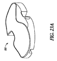
図27Aは、ハンドリング整合ボイド856を備えたハンドリング器具806に取り付けられたシム・コンポーネント810であって、シム・コンポーネント810を支承コンポーネント808とベース・コンポーネント812との間に挿入する前の状態のシム・コンポーネント810を示している。一例において、シム・コンポーネント810は厚さT1を有することができる。図27Bは、(近位から遠位への方向で)厚さが増大する付加的なシム・コンポーネント858,860,862及び864を示している。シム・コンポーネント858の厚さT2は、シム・コンポーネント810の厚さT1よりも大きくてよい。同様に、シム・コンポーネント860の厚さT3は、シム・コンポーネント858の厚さT2よりも大きくてよい。一例において、シム・コンポーネント810,858,860,862及び864の厚さは10mm〜14mmであってよい。
FIG. 27A shows a
脛骨補綴システム340に関して上述したように、脛骨上に埋め込まれた支承コンポーネント808とベース・コンポーネント812との間隔に基づいて、特定のシム・コンポーネントを選択して挿入することができる。また、図5の方法500に関して上述したように、シム・コンポーネント810,858,860,862及び864から選択されたシム・コンポーネントを挿入し、次いで異なるシム・コンポーネントを選択して最初に選択されたシム・コンポーネントと交換するべきかどうかを判断するためにテストを実施することができる。一例において、支承コンポーネント808のセンサ822を使用して膝関節の少なくとも一部における力又は圧力のバランスを分析するように、テストを実施することができる。収集された力データ又は圧力データが満足できるものではない場合、異なるシム・コンポーネントを挿入することができる。満足できる力データ又は圧力データが観察されるまで、これらのステップを繰り返すことができる。任意には、シムの選択とともに、又はシムの選択の代わりに、バランス・テストのデータが満足できるものではない場合に、外科医は靱帯切離によって靱帯バランスを調節することができる。センサ822及びフレーム818を含む支承コンポーネント808は、膝関節における力バランスに関する包括的な感知データ集合を提供するように形成することができる。
As described above with respect to the
図27Cは、厚さT6を有するシム・コンポーネント866を示している。一例において、シム・コンポーネント866の厚さT6は、シム・コンポーネント810の厚さT1よりも小さくてよい。一例において、シム・コンポーネント866の厚さT6は約6mmであってよい。他の例では、厚さT6は6mm未満又は6mm超であってよい。一例において、シム・コンポーネント866はシム・コンポーネント810,858,860,862及び864のうちの1つと組み合わせて使用して、支承コンポーネント808とベース・コンポーネント812との付加的な間隔を提供することができる。図27Cに示されているように、シム・コンポーネント866は、ハンドリング器具806と係合するためのアパーチャ868を含むことができ、シム・コンポーネントと支承コンポーネント808との間に挿入されるように形成することができる。
FIG. 27C shows a
試用補綴システム800のコンポーネントは、種々異なるサイズの膝関節に対応するために様々なサイズで利用することができる。一例では、外科医又は他の介護人は、テンプレートを使用して、試用補綴システム800のおおよその好適なサイズ又は形状を判定することができる。図28は複数のテンプレート880を示している。これらのテンプレートは、脛骨補綴システム804の好適なサイズ又は形状を選択する前に適切な脛骨トレーサイズを判定する際に使用するためにサイジング及び/又は成形することができる。テンプレート880は図示のように、最小サイズAから最大サイズFまでのサイズであってよい。
The components of the
図29はキット900の例を示している。キット900はユーザーインターフェイス902と、ハンドリング器具904と、複数のコンポーネント906とを含むことができる。コンポーネント906は、試用補綴システム800に関して上述したコンポーネントのうちのいくつか又は全て、或いはやはり上述のこのようなコンポーネントの関連変更形を含むことができる。ユーザーインターフェイスは、脛骨補綴システム804の支承コンポーネント808のセンサ822及びプロセッサ824に接続されるように形成することができる。ユーザーインターフェイス902は、センサ822又はプロセッサ824からのデータを処理し、このようなデータをヒストリカル・データベースと比較し、そしてユーザーインターフェイスのスクリーン上に1つ又はそれ以上のバランス判定事項を表示するように形成されたコンピュータ・デバイスを含むことができる。ユーザーインターフェイス902は小型で可搬性であり、また無線式であるように形成することができるので、ユーザーインターフェイス902を外科処置の区域、又は周辺区域内で使用することができる。いくつかの例では、ユーザーインターフェイス902は別のディスプレイ装置、例えば外科処置区域内のコンピュータ又はTVモニタに接続することができる。
FIG. 29 shows an example of the
一例において、キット900は、図27Bに関して上述したように、仮大腿骨補綴物802と複数のシム・コンポーネントとを含む、試用補綴システム800のための全てのコンポーネントを含むことができる。一例において、キット900は前縁と後縁との高さ差、及び/又は内側縁と外側縁との高さ差を有する少なくとも1つのシム・コンポーネントを含むことができる。キット900は、一緒に配置される膝処置用コンポーネントのうちのいくつか又は全てを有し得るように設計することができる。キット900のコンポーネントはトレー907内部に収容することができる。トレーは、これに収容されたコンポーネントのうちの1つ又はそれ以上と一緒に、単回の使用後に廃棄することができる。一例において、キット900は、試用補綴システム800コンポーネントのうちのいくつかを収容することができ、そして、他のコンポーネントのうちのいくつかを外科処置中に別個に用意することができる。
In one example, the
図30は、ユーザーインターフェイス902上に生成して表示し得るデジタル画像908の一例を示している。上記のように、脛骨補綴システム804の支承コンポーネント808は、複数のセンサ822を有するセンサ・プレート820を含むことができる。一例において、センサ・プレート820は24個のセンサ形態を有することができる。センサ・プレート820はプロセッサ824を含むことができる。プロセッサは、データをユーザーインターフェイス902に伝達する前に複数のセンサ822からのデータを受信して処理するように形成することができる。或いは、プロセッサ824はユーザーインターフェイス902のコンピュータ・デバイスと一体化することもできる。ユーザーインターフェイス902はセンサ・プレート820と有線接続又は無線接続することができる。有線接続又は無線接続は、あらゆるタイプのネットワーク、例えばインターネット、電話ネットワーク、ケーブル・ネットワーク、又は無線ネットワークを利用することができる。
FIG. 30 illustrates an example of a
デジタル画像908は、センサ822と整合する脛骨補綴物800の区域を二次元的(図示)、又は任意には三次元的に表示したものであってよい。センサ822からのデータを多点データ・レジストリ内にマッピングすることができる。一例において24点データ・レジストリは、24個のセンサ822を有することに基づいてマッピングされる。他の例では、データ・レジストリは、センサ・プレート820上に24個未満又は24個超のセンサ822を有することに基づいて24個未満又は24個超の点を有することができる。上述のように、センサ822と整合する開口828を有するフレーム818を含む支承コンポーネント808の形態及び設計は、独立した感知区域を可能にし、これらの感知区域はユーザーインターフェイス902上に認識可能にマッピングして提示することができる。
The
図31は、ユーザーインターフェイス902上に表示し得るデジタル画像910の例を示している。デジタル画像912は、センサ・プレート820上のセンサ822のそれぞれによって生成された力の値を示すことができる。生成された力の値は、上側部分816の突起850、又はセンサ822と相互作用する、上側部分816と下側部分823との間に延びるカラムによって伝達された力の結果であってよい。デジタル画像912内に示されたデータに基づいて、ユーザーインターフェイス902のコンピュータ装置は画像914を生成することができる。画像914は、仮脛骨補綴システム804上の2つの半部又は4つの象限のそれぞれにおける集合力を含むことができる。画像914は、仮脛骨補綴システムの内側M、外側L、前側A、及び後側P、又はこれらの組み合わせを表すインジケータを含むことができる。力データの内側・外側間及び前側・後側間の中心を示す画像916をユーザーインターフェイス902によって生成することもできる。
FIG. 31 shows an example of a
図32は、ユーザーインターフェイス902上に表示し得る別のデジタル画像918の例を示す。外科医又は他のユーザーは、屈曲及び/又は伸展の許容力限界を表すグリーンゾーン又は安全ゾーンとして概念化することができる特定ゾーンを選択することができる。屈曲の場合、グリーンゾーンは例えば極限点920及び922によって表すことができ、また伸展の場合、グリーンゾーンは例えば極限点924及び926によって表すことができる。任意にはグリーンゾーンは、少なくとも一つには、1回又は2回以上の患者試行から得られた統計学的に重要なヒストリカル・データに基づいて確立することができる。例えば、多数回の試行から得られた実験データを収集したら、(分析プログラム、又は別の外部プログラムによって)データを統計的に分析することによって、推奨所定圧力基準、すなわち上限及び下限を形成し、これにより外科医が潜在的な高圧測定値を認識するのを助けることができる。推奨所定圧力基準は、所定の条件下での統計的に正常な閾値、及び許容限界を定義することができ、そしてより多くの情報がデータベース内で利用可能になるのに伴って絶えず調節することができる。
FIG. 32 shows an example of another digital image 918 that may be displayed on the
センサ822によって生成され、センサ822から取得された力の値を次いでマッピングし、例えば図33の画像928で示すことができる。画像928は、グリーンゾーンと比較してあまりにも高い力又は力ゾーン(符号930)、許容グリーンゾーン内の力又は力ゾーン(符号931)、そしてグリーンゾーンと比較してあまりにも低い力又は力ゾーン(符号932)(例えば内側ゾーン、外側ゾーン、前ゾーン、後ゾーン、内側/前ゾーン、内側/後ゾーン、外側/前ゾーン、外側/後ゾーン)を指示することができる。ユーザーインターフェイスのコンピュータ・デバイスは、取得した力データをグリーンゾーンデータと比較するように形成することができる。グリーンゾーンデータはユーザーインターフェイスのハードドライブ上のソフトウェア内に記憶することができる。図34は、外科医によって選択されたグリーンゾーンに基づく複数の画像を有するユーザーインターフェイス902を示している。1つ又はそれ以上の画像を外科医によって使用することにより、例えば過剰の力又は力ゾーンを補正することができる。
The force values generated by the
他の例では、外科医をガイドするために付加的な又は別のデータを表示することができる。図31〜図34の力の値として示された数値は、外科医による使用のために生成して表示し得るデータのタイプを示すための一例である。表示された具体的な数値は制限的であることを意図するものではなく、膝関節のバランス又はアンバランスを判定するための一例である。センサによって生成されデータ点レジストリ内にマッピングされた数値を、前に収集された経時的数値と比較することができる。これらの経時的数値は十分ないしは不十分なバランス及び整合状態を指示することができる。 In other examples, additional or alternative data can be displayed to guide the surgeon. The numerical values shown as force values in FIGS. 31-34 are an example to indicate the type of data that can be generated and displayed for use by the surgeon. The specific numerical values displayed are not intended to be limiting but are examples for determining the balance or unbalance of the knee joint. The numerical value generated by the sensor and mapped in the data point registry can be compared with the numerical value over time collected previously. These chronological values can indicate a sufficient or insufficient balance and alignment.
一例において、上記のように、ユーザーインターフェイス902はコンピュータ・デバイスを含むように形成することができ、ユーザーインターフェイス902はキット900の一部として提供することができる。他の例では、センサ822及びプロセッサ824を任意の他のタイプのコンピュータ・デバイスに接続することによって、センサ822からのデータに基づいて上記タイプのデータを生成することができる。
In one example, as described above,
締めくくりの注記:
既存の仮システム、キット、及び方法では、角度付き骨切り(例えば膝の関節線に対して平行でない骨切り)を脛骨の近位端又は大腿骨の遠位端に施す場合に、外科医は骨関節運動特性を洞察することができない。既存の仮システム、キット、及び方法の場合、さらに、永久脛骨補綴システムの適切な形態に達するために比較的数多くの仮コンポーネントの積み重ねが必要となり、或いは仮膝関節バランスをリアルタイムに示す力又は圧力感知データを提供することができない。本発明の仮システム、キット、及び方法は、外側縁とは異なる高さを有する内側縁、又は後縁とは異なる高さを有する前縁、のうちの一方又は両方を有するシム・コンポーネント、又は支承コンポーネント、支承支持コンポーネント、又はシム・コンポーネントと結合又は一体化されたセンサを含むことができる。このようなシム・コンポーネント形態は、大腿骨又は脛骨に角度付き骨切りを施す前に、この骨切りに関する膝関節運動特性を外科医が洞察するのを可能にし、そして外科的サイジング中に必要となる仮コンポーネントの個数を低減することができる。センサはリアルタイムの膝関節バランス・テストを容易にすることができる。
Closing note:
In existing provisional systems, kits, and methods, a surgeon may use a bone when an angled osteotomy (eg, an osteotomy that is not parallel to the knee joint line) is applied to the proximal end of the tibia or the distal end of the femur. There is no insight into joint motion characteristics. In the case of existing temporary systems, kits and methods, a relatively large number of temporary components need to be stacked to reach the proper form of a permanent tibial prosthesis system, or force or pressure that indicates the knee joint balance in real time. Sensing data cannot be provided. The temporary system, kit and method of the present invention comprise a shim component having one or both of an inner edge having a height different from the outer edge, or a leading edge having a height different from the rear edge, or It may include a sensor coupled or integrated with a bearing component, a bearing support component, or a shim component. Such a shim component configuration allows the surgeon to gain insight into the knee motion characteristics associated with this osteotomy prior to making an angled osteotomy to the femur or tibia and is required during surgical sizing The number of temporary components can be reduced. The sensor can facilitate real-time knee balance testing.
上記「詳細な説明」は添付の図面を参照することを含み、これらの図面は「詳細な説明」の一部を形成する。図面は、本発明の脛骨補綴システム、キット、及び方法を実施し得る特定の実施態様を例示のために示している。これらの実施態様は本明細書中では「例(examples)」とも呼ばれる。特定の例が左膝又は右膝に関して示され説明されているが、言うまでもなく、本開示内容は左膝又は右膝の両方に対して等しく適用することができる。全ての例は部分又は全膝置換処置に用いることもできる。 The above “detailed description” includes reference to the accompanying drawings, which form a part of the “detailed description”. The drawings show, by way of illustration, specific embodiments in which the tibial prosthetic system, kit, and method of the present invention may be implemented. These embodiments are also referred to herein as “examples”. Although specific examples are shown and described with respect to the left or right knee, it will be appreciated that the present disclosure is equally applicable to both the left or right knee. All examples can also be used for partial or total knee replacement procedures.
上記「詳細な説明」は例示を意図するものであって、制限的ではない。例えば上記例(又はこれらの1つ又はそれ以上のエレメント)を互いに組み合わせて使用することができる。上記記述を検討すれば、例えば当業者であれば他の実施態様を用いることができる。また種々の特徴又はエレメントを一緒にグループ分けすることにより開示内容を簡素化することもできる。このことは、請求項以外で開示された特徴がいずれかの請求項に必須であることを意図するものと解釈されるべきではない。それどころか、本発明の対象は、開示された特定実施態様の全ての特徴にあるとは限らない。従って、下記請求項は「詳細な説明」に組み込まれ、各請求項は別個の実施態様としてそれ自体で成り立つ。本発明の範囲は、添付の請求項を参照して、このような請求項と同等のものの全範囲とともに決定されるべきである。 The above “detailed description” is intended to be illustrative and not restrictive. For example, the above examples (or one or more of these elements) can be used in combination with each other. In consideration of the above description, other embodiments can be used by those skilled in the art, for example. It is also possible to simplify the disclosure by grouping various features or elements together. This should not be interpreted as intending that a feature disclosed outside of a claim is essential to any claim. On the contrary, the subject matter of the invention is not necessarily all features of the specific embodiments disclosed. Thus, the following claims are hereby incorporated into the Detailed Description, with each claim standing on its own as a separate embodiment. The scope of the invention should be determined with reference to the appended claims, along with the full scope of equivalents to such claims.
本文献と、引用することにより組み込まれた文献との利用に矛盾が生じた場合には、本文献における利用が優先する。 If there is a contradiction in the use of this document and the document incorporated by reference, the use in this document takes precedence.
本文献において、「a」又は「an」という用語は、他の事例又は「少なくとも1つ(at least one)」又は「1つ又はそれ以上(one or more)」の使用から独立して、1つ又はそれ以上を含むために用いられる。本文献において「又は(or)」という用語は、非排他的orを意味するために用いられるので、「A又はB」は他に指示がない限り、「AであるがBではない」、「BであるがAではない」、そして「AでありBである」を含む。この文献において、「前方(anterior)」は概ね患者前面に向かう方向を意味し、「後方(posterior)」は概ね患者背面に向かう方向を意味し、「内側(medial)」は概ね患者中央に向かう方向を意味し、「外側(lateral)」は概ね患者側方に向かう方向を意味する。この文献において、「前/後方向」という語句は、前から後への又は後から前への方向を含むために使用される。 In this document, the terms “a” or “an” are independent of other cases or use of “at least one” or “one or more”. Used to include one or more. In this document, the term “or” is used to mean non-exclusive or, so “A or B” is “A but not B” unless otherwise indicated, "B but not A" and "A and B". In this document, “anterior” generally refers to the direction toward the front of the patient, “posterior” generally refers to the direction toward the back of the patient, and “medial” generally refers to the center of the patient. Means the direction, “lateral” means the direction towards the patient side. In this document, the phrase “front / rear direction” is used to include a front-to-back or back-to-front direction.
添付の請求項において「含む(including)」及び「ここで(in which)」という用語は、それぞれ「含む(comprising)」及び「ここで(wherein)」という用語と同等の平易な英語として使用される。「含む(including)」及び「含む(comprising)」はオープンエンドであり、すなわち請求項におけるこのような用語の後に挙げられるエレメントに加えられたエレメントを含むシステム、キット、又は方法も、依然としてその請求項の範囲に含まれると見なされる。また下記請求項において、「キット」の請求項はとりわけ、少なくとも1つが異なる高さを含む一連の新規シム・コンポーネント、センサ、支承コンポーネント、及び新規シム・コンポーネントとの機能的関係を有するハンドリング器具コンポーネントを保護するように意図される。さらに、下記請求項において、「第1」、「第2」及び「第3」などという用語は標識として用いられるにすぎず、対象物に数的要件を与えるものではない。 In the appended claims, the terms “including” and “in which” are used as plain English equivalent to the terms “comprising” and “wherein”, respectively. The “Including” and “comprising” are open-ended, that is, systems, kits, or methods that include elements in addition to elements listed after such terms in the claims are still claimed. It is considered to be within the scope of the term. Also in the following claims, the “kit” claim includes, among other things, a series of new shim components, sensors, bearing components, and handling instrument components that have a functional relationship with the new shim components, including at least one different height. Is intended to protect. Furthermore, in the following claims, the terms “first”, “second”, “third”, etc. are only used as labels and do not give numerical requirements to the object.
「要約書」は、技術開示内容の性質を読者が素早く解明するのを可能にするために提供される。これは、請求項の範囲又は意味を解釈又は限定するためには使用されないという了解のもとに提出される。 A “summary” is provided to allow the reader to quickly elucidate the nature of the technical disclosure. It is submitted with the understanding that it will not be used to interpret or limit the scope or meaning of the claims.
Claims (32)
上関節面とベース・コンポーネント係合形体を備えた下面とを有する支承コンポーネントと、
支承コンポーネント係合形体を有する上面と下面とを有するベース・コンポーネントと、
シム・コンポーネントと、
を含み、
前記支承コンポーネントと前記ベース・コンポーネントとを取り外し可能に互いに係合させ得るように、前記支承コンポーネント係合形体が前記ベース・コンポーネント係合形体と嵌合するように形成されており、
前記ベース・コンポーネント係合形体と前記支承コンポーネント係合形体との嵌合が、前記支承コンポーネントと前記ベース・コンポーネントとの間の前/後運動、又は内側/外側運動のうちの少なくとも一方を阻止し、
前記シム・コンポーネントを前記支承コンポーネント及び前記ベース・コンポーネントのうちの少なくとも一方と取り外し可能に係合させるために、前記シム・コンポーネントは、前記支承コンポーネントと前記ベース・コンポーネントとが互いに係合させられたときに、前記支承コンポーネントの下面と前記ベース・コンポーネントの上面との間で摺動可能であるように形成されており、
前記シム・コンポーネントが、外側縁とは異なる高さを有する内側縁、又は後縁とは異なる高さを有する前縁、のうちの一方又は両方を含んでおり、
前記シム・コンポーネントは前記ベース・コンポーネント係合形体又は前記支承コンポーネント係合形体の通過を可能にするようにサイジングされ成形されており、これにより前記支承コンポーネントと前記ベース・コンポーネントとが互いに係合させられて前記シム・コンポーネントが前記支承コンポーネントと前記ベース・コンポーネントとの間で摺動したときに、前記ベース・コンポーネント係合形体と前記支承コンポーネント係合形体とが互いに嵌合したままである、
脛骨補綴システム。 A tibial prosthesis system,
A bearing component having an upper articulating surface and a lower surface with a base component engaging feature ;
A base component having an upper surface and a lower surface having a bearing component engagement features,
And Shi-time component,
Including
The bearing component engagement feature is configured to mate with the base component engagement feature so that the bearing component and the base component can be removably engaged with each other;
The mating of the base component engagement feature and the bearing component engagement feature prevents at least one of forward / backward movement or inward / outward movement between the bearing component and the base component. ,
In order to removably engage the shim component with at least one of the bearing component and the base component, the shim component has the bearing component and the base component engaged with each other. Occasionally, it is formed so as to be sliding between the lower surface and the upper surface of the base component of the bearing component,
The shim component includes one or both of an inner edge having a height different from the outer edge or a front edge having a height different from the rear edge ;
The shim component is sized and shaped to allow passage of the base component engagement feature or the bearing component engagement feature so that the bearing component and the base component engage each other. The base component engagement feature and the support component engagement feature remain engaged with each other when the shim component is slid between the support component and the base component.
Tibial prosthesis system.
ベース・コンポーネント係合形体を有する仮支承コンポーネントと、
支承コンポーネント係合形体を有する仮ベース・コンポーネントと、
異なるサイズの一連のシム・コンポーネントと、
を含み、
前記仮支承コンポーネントと前記仮ベース・コンポーネントとを取り外し可能に互いに係合させ得るように、前記支承コンポーネント係合形体が前記ベース・コンポーネント係合形体と嵌合するように形成されており、
前記ベース・コンポーネント係合形体と前記支承コンポーネント係合形体との嵌合が、前記仮支承コンポーネントと前記仮ベース・コンポーネントとの間の前/後運動、又は内側/外側運動のうちの少なくとも一方を阻止し、
前記シム・コンポーネントの少なくとも1つが、外側縁とは異なる高さを有する内側縁、又は後縁とは異なる高さを有する前縁、のうちの一方又は両方を含んでおり、
前記シム・コンポーネントを前記仮支承コンポーネント及び前記仮ベース・コンポーネントのうちの少なくとも一方と取り外し可能に係合させるために、それぞれの前記シム・コンポーネントは、前記仮支承コンポーネントと前記仮ベース・コンポーネントとの間に挿入可能であるように形成されており、
前記仮支承コンポーネントと前記仮ベース・コンポーネントとが互いに係合させられて前記シム・コンポーネントが前記仮支承コンポーネントと前記仮ベース・コンポーネントとの間に挿入されたときに、前記シム・コンポーネントが前記ベース・コンポーネント係合形体と前記支承コンポーネント係合形体との嵌合を妨げることがなく、これにより前記シム・コンポーネントが前記仮支承コンポーネントと前記仮ベース・コンポーネントとの間に挿入されたときに前記仮支承コンポーネントと前記仮ベース・コンポーネントとが相互の係合状態を維持する、
脛骨補綴システム。 A tibial prosthesis system,
A temporary bearing component having a base component engagement feature;
A temporary base component having a bearing component engagement feature;
A series of shim components of different sizes ,
Including
The bearing component engagement feature is configured to mate with the base component engagement feature such that the temporary support component and the temporary base component can be removably engaged with each other;
The mating of the base component engagement feature and the bearing component engagement feature comprises at least one of a front / rear motion or an inner / outer motion between the temporary bearing component and the temporary base component. Stop,
At least one of the shim components includes one or both of an inner edge having a height different from the outer edge or a leading edge having a height different from the rear edge ;
In order to removably engage the shim component with at least one of the temporary bearing component and the temporary base component, each of the shim components includes a temporary bearing component and a temporary base component. It is formed so that it can be inserted between
When the temporary bearing component and the temporary base component are engaged with each other and the shim component is inserted between the temporary bearing component and the temporary base component, the shim component is Without interfering with the engagement between the component engagement feature and the bearing component engagement feature, so that the shim component is inserted into the temporary support component and the temporary base component when the temporary component is inserted; The bearing component and the temporary base component maintain mutual engagement;
Tibial prosthesis system .
請求項14に記載の脛骨補綴システム。The tibial prosthesis system of claim 14.
上関節面とベース・コンポーネント係合形体を備えた下面と有する支承コンポーネントと、
支承コンポーネント係合形体を備えた上面と下面とを有するベース・コンポーネントと、
1つ又はそれ以上のシム・コンポーネントと、
を含み、
前記支承コンポーネントと前記ベース・コンポーネントとを取り外し可能に互いに結合し得るように、前記支承コンポーネント係合形体が、前記ベース・コンポーネント係合形体と嵌合するように形成されており、
前記1つ又はそれ以上のシム・コンポーネントは、前記支承コンポーネント及び前記ベース・コンポーネントのうちの少なくとも一方と取り外し可能に係合するために、前記支承コンポーネントの下面と前記ベース・コンポーネントの上面との間で摺動可能であるように形成されており、
前記1つ又はそれ以上のシム・コンポーネントのうちの少なくとも1つが、外側縁とは異なる高さを有する内側縁、又は後縁とは異なる高さを有する前縁、のうちの一方又は両方を含んでおり、
前記支承コンポーネントと前記ベース・コンポーネントとが互いに結合されて前記1つ又はそれ以上のシム・コンポーネントが前記仮支承コンポーネントと前記仮ベース・コンポーネントとの間で摺動したときに、前記1つ又はそれ以上のシム・コンポーネントが前記ベース・コンポーネント係合形体と前記支承コンポーネント係合形体との嵌合を分断することがなく、これにより前記1つ又はそれ以上のシム・コンポーネントが前記支承コンポーネントと前記ベース・コンポーネントとの間で摺動したときに前記支承コンポーネントと前記ベース・コンポーネントとの結合が妨げられない、
脛骨補綴システム。 A tibial prosthesis system,
A bearing component with a lower surface having a superior facet and the base component engagement features,
A base component having an upper surface and a lower surface provided with a bearing component engagement features,
And one or more shim components,
Including
The bearing component engagement feature is configured to mate with the base component engagement feature so that the bearing component and the base component can be removably coupled to each other;
The one or more shim components are between a lower surface of the bearing component and an upper surface of the base component for releasably engaging at least one of the bearing component and the base component. in is formed so as to be slidable,
At least one of the one or more shim components includes one or both of an inner edge having a height different from the outer edge, or a leading edge having a height different from the rear edge. and de,
The one or more when the bearing component and the base component are coupled together and the one or more shim components slide between the temporary bearing component and the temporary base component. The above shim components do not break the fit between the base component engagement feature and the support component engagement feature so that the one or more shim components can be coupled to the support component and the base. The coupling between the bearing component and the base component is not hindered when sliding between the components,
Tibial prosthesis system.
ベース・コンポーネント係合形体を有する支承コンポーネントと、A bearing component having a base component engagement feature;
支承コンポーネント係合形体を有するベース・コンポーネントと、A base component having a bearing component engagement feature;
前記支承コンポーネントと前記ベース・コンポーネントとの間に挿入されるように形成されたシム・コンポーネントと、A shim component configured to be inserted between the bearing component and the base component;
を含み、Including
前記支承コンポーネントを前記ベース・コンポーネントと取り外し可能に結合するために、前記ベース・コンポーネント係合形体と前記支承コンポーネント係合形体とが互いに嵌合するように形成されており、The base component engagement feature and the support component engagement feature are configured to mate with each other to removably couple the support component with the base component;
前記ベース・コンポーネント係合形体と前記支承コンポーネント係合形体との嵌合が、前記支承コンポーネントと前記ベース・コンポーネントとの間の前/後運動、又は内側/外側運動のうちの少なくとも一方を阻止し;そしてThe mating of the base component engagement feature and the bearing component engagement feature prevents at least one of forward / backward movement or inward / outward movement between the bearing component and the base component. And
前記シム・コンポーネントが、外側縁とは異なる高さを有する内側縁、又は後縁とは異なる高さを有する前縁、のうちの一方又は両方を含んでおり、The shim component includes one or both of an inner edge having a height different from the outer edge or a front edge having a height different from the rear edge;
前記シム・コンポーネントは、前記シム・コンポーネントが前記支承コンポーネントと前記ベース・コンポーネントとの間に挿入されたときに、前記支承コンポーネントと前記ベース・コンポーネントとの間に間隔を提供し、The shim component provides a spacing between the bearing component and the base component when the shim component is inserted between the bearing component and the base component;
前記シム・コンポーネントは前記支承コンポーネント及び前記ベース・コンポーネントのうちの少なくとも一方と取り外し可能に係合することができ、The shim component can removably engage with at least one of the bearing component and the base component;
前記シム・コンポーネントは後方凹部を含み、前記支承コンポーネントと前記ベース・コンポーネントとが互いに結合されて前記シム・コンポーネントが前記支承コンポーネントと前記ベース・コンポーネントとの間に挿入されたときに、前記後方凹部は前記ベース・コンポーネント係合形体と前記支承コンポーネント係合形体とが互いに嵌合したままであることを可能にし、The shim component includes a back recess, the back recess when the bearing component and the base component are coupled together and the shim component is inserted between the support component and the base component. Allows the base component engagement feature and the bearing component engagement feature to remain engaged with each other;
前記シム・コンポーネントが前記支承コンポーネントと前記ベース・コンポーネントとの間に挿入されたときに、前記シム・コンポーネントは前記支承コンポーネントと前記ベース・コンポーネントとの結合を妨げない、When the shim component is inserted between the bearing component and the base component, the shim component does not interfere with the coupling between the bearing component and the base component;
脛骨補綴システム。Tibial prosthesis system.
上面とベース係合形体を備えた下面とを有する支承体と、A bearing body having an upper surface and a lower surface with a base engagement feature;
支承体係合形体を備えた上面と下面とを有するベースと、A base having an upper surface and a lower surface with a bearing engagement feature;
シムと、Sim and
を含み、Including
前記支承体及び前記ベースは、前記支承体係合形体と前記ベース係合形体との嵌合を介して取り外し可能に互いに結合することができ、The bearing body and the base can be removably coupled to each other via a fit between the bearing body engaging feature and the base engaging feature;
前記ベース係合形体と前記支承体係合形体との嵌合が、前記支承体と前記ベースとの間の前/後運動、又は内側/外側運動のうちの少なくとも一方を阻止し、The mating of the base engagement feature and the bearing engagement feature prevents at least one of front / rear movement or medial / lateral movement between the bearing and the base;
前記シムが、外側縁とは異なる高さを有する内側縁、又は後縁とは異なる高さを有する前縁、のうちの一方又は両方を含んでおり、前記シムは、前記支承体及び前記ベースのうちの少なくとも一方に設けられたシム嵌合形体との係合のために形成された少なくとも1つの嵌合形体を有しており、The shim includes one or both of an inner edge having a height different from the outer edge, or a front edge having a height different from the rear edge, the shim comprising the bearing body and the base Having at least one mating feature formed for engagement with a shim mating feature provided on at least one of the
前記シムに設けられた前記少なくとも1つの嵌合形体を、前記支承体及び前記ベースのうちの少なくとも一方に設けられた前記シム嵌合形体と取り外し可能に係合させるために、前記シムは、前記支承体と前記ベースとが互いに係合させられたときに、前記支承体と前記ベースとの間で摺動可能であり、In order to removably engage the at least one mating feature provided on the shim with the shim mating feature provided on at least one of the bearing body and the base, the shim includes: Slidable between the support and the base when the support and the base are engaged with each other;
前記シムが前記支承体と前記ベースとの間に間隔を提供し、The shim provides a gap between the bearing and the base;
前記シムは前記支承体係合形体と前記ベース係合形体との結合を妨げず、The shim does not interfere with the coupling of the bearing engagement feature and the base engagement feature;
前記シムが前記支承体と前記ベースとの間で摺動したときに、前記支承体と前記ベースとが互いに結合したままである、When the shim slides between the support and the base, the support and the base remain coupled to each other;
脛骨補綴システム。Tibial prosthesis system.
Applications Claiming Priority (11)
| Application Number | Priority Date | Filing Date | Title |
|---|---|---|---|
| US201261618376P | 2012-03-30 | 2012-03-30 | |
| US61/618,376 | 2012-03-30 | ||
| US201261740268P | 2012-12-20 | 2012-12-20 | |
| US61/740,268 | 2012-12-20 | ||
| US13/836,665 US9149206B2 (en) | 2012-03-30 | 2013-03-15 | Tibial prosthesis systems, kits, and methods |
| US13/836,665 | 2013-03-15 | ||
| US13/837,774 | 2013-03-15 | ||
| US13/837,774 US20130261758A1 (en) | 2012-03-30 | 2013-03-15 | Tibial prosthesis systems, kits, and methods |
| US13/837,294 | 2013-03-15 | ||
| US13/837,294 US9492290B2 (en) | 2012-03-30 | 2013-03-15 | Tibial prosthesis systems, kits, and methods |
| PCT/US2013/034286 WO2013148954A1 (en) | 2012-03-30 | 2013-03-28 | Tibial prosthesis systems, kits, and methods |
Publications (3)
| Publication Number | Publication Date |
|---|---|
| JP2015512307A JP2015512307A (en) | 2015-04-27 |
| JP2015512307A5 JP2015512307A5 (en) | 2016-03-10 |
| JP5909021B2 true JP5909021B2 (en) | 2016-04-26 |
Family
ID=49235951
Family Applications (2)
| Application Number | Title | Priority Date | Filing Date |
|---|---|---|---|
| JP2015503563A Active JP6185557B2 (en) | 2012-03-30 | 2013-03-28 | Tibial prosthesis system, kit, and method |
| JP2015503562A Active JP5909021B2 (en) | 2012-03-30 | 2013-03-28 | Tibial prosthesis system, kit, and method |
Family Applications Before (1)
| Application Number | Title | Priority Date | Filing Date |
|---|---|---|---|
| JP2015503563A Active JP6185557B2 (en) | 2012-03-30 | 2013-03-28 | Tibial prosthesis system, kit, and method |
Country Status (8)
| Country | Link |
|---|---|
| US (5) | US20130261758A1 (en) |
| EP (3) | EP2830543B1 (en) |
| JP (2) | JP6185557B2 (en) |
| CN (2) | CN104379094B (en) |
| AU (2) | AU2013238046B2 (en) |
| CA (2) | CA2869007C (en) |
| ES (2) | ES2597733T3 (en) |
| WO (2) | WO2013148954A1 (en) |
Families Citing this family (75)
| Publication number | Priority date | Publication date | Assignee | Title |
|---|---|---|---|---|
| GB201006716D0 (en) * | 2010-04-22 | 2010-06-09 | Depuy Ireland | A composite trial prosthesis |
| US8764840B2 (en) | 2010-07-24 | 2014-07-01 | Zimmer, Inc. | Tibial prosthesis |
| EP3348237B1 (en) | 2010-07-24 | 2020-01-01 | Zimmer, Inc. | Asymmetric tibial components for a knee prosthesis |
| US8591594B2 (en) | 2010-09-10 | 2013-11-26 | Zimmer, Inc. | Motion facilitating tibial components for a knee prosthesis |
| US8603101B2 (en) | 2010-12-17 | 2013-12-10 | Zimmer, Inc. | Provisional tibial prosthesis system |
| US9597090B2 (en) | 2010-12-17 | 2017-03-21 | Zimmer, Inc. | Cut guide attachment for use in tibial prosthesis systems |
| US8728167B2 (en) | 2011-01-10 | 2014-05-20 | Howmedica Osteonics Corp. | Bicruciate retaining tibial baseplate design and method of implantation |
| US8968412B2 (en) | 2011-06-30 | 2015-03-03 | Depuy (Ireland) | Trialing system for a knee prosthesis and method of use |
| GB201114059D0 (en) | 2011-08-16 | 2011-09-28 | Depuy Ireland | Attachment mechanism |
| AU2012337369B2 (en) | 2011-11-18 | 2015-07-30 | Zimmer, Inc. | Tibial bearing component for a knee prosthesis with improved articular characteristics |
| EP2782525B1 (en) | 2011-11-21 | 2016-07-20 | Zimmer, Inc. | Tibial baseplate with asymmetric placement of fixation structures |
| US9649427B2 (en) | 2011-12-28 | 2017-05-16 | Xerem Medical Ltd. | System and method for blood filtering and/or treatment |
| US8702803B2 (en) | 2011-12-29 | 2014-04-22 | Mako Surgical Corp. | Locking assembly for tibial prosthesis component |
| US8911501B2 (en) | 2011-12-29 | 2014-12-16 | Mako Surgical Corp. | Cruciate-retaining tibial prosthesis |
| ES2869958T3 (en) | 2012-01-30 | 2021-10-26 | Zimmer Inc | Asymmetric tibial components for a knee replacement |
| US9216086B2 (en) * | 2012-02-01 | 2015-12-22 | Zimmer, Inc. | Adjustable provisional component of a medical device |
| US20130261758A1 (en) | 2012-03-30 | 2013-10-03 | Zimmer, Inc. | Tibial prosthesis systems, kits, and methods |
| JP2015517361A (en) | 2012-05-18 | 2015-06-22 | オースアライン・インコーポレイテッド | Apparatus and method for knee arthroplasty |
| US9937063B2 (en) * | 2013-02-14 | 2018-04-10 | Zimmer, Inc. | Trialing for prosthetic component |
| US9345578B2 (en) | 2013-02-22 | 2016-05-24 | Stryker Corporation | Bicruciate retaining tibial implant system |
| BR112015024137A2 (en) | 2013-03-20 | 2017-07-18 | Polaris Surgical Llc | computer-implemented method and knee balancing system to control performance parameters associated with an orthopedic joint, and, force sensor module |
| US9925052B2 (en) | 2013-08-30 | 2018-03-27 | Zimmer, Inc. | Method for optimizing implant designs |
| US9592133B2 (en) | 2013-09-23 | 2017-03-14 | Zimmer, Inc. | Spacer block |
| ES2841926T3 (en) | 2013-10-15 | 2021-07-12 | Xpandortho Inc | Actuated positioning device for arthroplasty |
| CA2930668C (en) | 2013-11-13 | 2020-11-03 | Zimmer, Inc. | Augment system for an implant |
| TWM479734U (en) * | 2014-02-27 | 2014-06-11 | United Orthopedic Corp | Stack-up assembly for tibial insert trial |
| US9861491B2 (en) * | 2014-04-30 | 2018-01-09 | Depuy Ireland Unlimited Company | Tibial trial system for a knee prosthesis |
| JP6662862B2 (en) | 2014-09-24 | 2020-03-11 | デピュイ・アイルランド・アンリミテッド・カンパニーDepuy Ireland Unlimited Company | Surgical planning and methods |
| US10154239B2 (en) | 2014-12-30 | 2018-12-11 | Onpoint Medical, Inc. | Image-guided surgery with surface reconstruction and augmented reality visualization |
| JP6921754B2 (en) * | 2015-03-24 | 2021-08-18 | エクスパンドーソ,インコーポレイテッド | Balancing device for arthroplasty and usage |
| FR3034652B1 (en) * | 2015-04-08 | 2017-04-28 | Michel Bonnin | TIBIAL IMPLANT FOR KNEE PROSTHESIS |
| US9668883B2 (en) * | 2015-08-19 | 2017-06-06 | Depuy Ireland Unlimited Company | Trial kit for knee prosthesis system |
| CN108135701B (en) | 2015-09-21 | 2019-12-24 | 捷迈有限公司 | Prosthesis system including tibial bearing component |
| US10357255B2 (en) | 2015-10-08 | 2019-07-23 | Howmedica Osteonics Corp. | Globalized total knee instrumentation |
| US10537445B2 (en) | 2015-10-19 | 2020-01-21 | Depuy Ireland Unlimited Company | Surgical instruments for preparing a patient's tibia to receive an implant |
| US10195056B2 (en) | 2015-10-19 | 2019-02-05 | Depuy Ireland Unlimited Company | Method for preparing a patient's tibia to receive an implant |
| CN105342730A (en) * | 2015-11-30 | 2016-02-24 | 北京爱康宜诚医疗器材股份有限公司 | Knee joint prosthesis stress detecting system |
| WO2017116346A1 (en) * | 2015-12-29 | 2017-07-06 | Tobb Ekonomi Ve Teknoloji Universitesi | Intervertebral disc system with monitoring capabilities |
| EP4327769A2 (en) | 2016-03-12 | 2024-02-28 | Philipp K. Lang | Devices and methods for surgery |
| WO2017185108A2 (en) * | 2016-04-28 | 2017-11-02 | Medfit Beratungs-Und Beteiligunges.M.B.H | Dynamic ligament balancing system (dlb) |
| CN105832448A (en) * | 2016-05-17 | 2016-08-10 | 嘉思特华剑医疗器材(天津)有限公司 | Intelligent knee joint tibia platform test pad module |
| US10470900B2 (en) * | 2016-06-17 | 2019-11-12 | Paragon 28, Inc. | Implants, devices, systems, kits and methods of implanting |
| US10231840B2 (en) | 2016-07-27 | 2019-03-19 | Howmedica Osteonics Corp. | Low profile tibial baseplate with fixation members |
| CN110022798A (en) * | 2016-12-06 | 2019-07-16 | 捷迈有限公司 | Shin bone plug-in unit |
| WO2018119360A1 (en) | 2016-12-22 | 2018-06-28 | Orthosensor Inc. | Surgical apparatus to support installation of a prosthetic component and method therefore |
| US11291437B2 (en) | 2016-12-22 | 2022-04-05 | Orthosensor Inc. | Tilting surgical tensor to support at least one bone cut |
| US11284873B2 (en) | 2016-12-22 | 2022-03-29 | Orthosensor Inc. | Surgical tensor where each distraction mechanism is supported and aligned by at least two guide shafts |
| US11185425B2 (en) | 2016-12-22 | 2021-11-30 | Orthosensor Inc. | Surgical tensor configured to distribute loading through at least two pivot points |
| US11266512B2 (en) | 2016-12-22 | 2022-03-08 | Orthosensor Inc. | Surgical apparatus to support installation of a prosthetic component and method therefore |
| US11751944B2 (en) | 2017-01-16 | 2023-09-12 | Philipp K. Lang | Optical guidance for surgical, medical, and dental procedures |
| CN114010374A (en) * | 2017-02-27 | 2022-02-08 | 捷迈有限公司 | Knee prosthesis implant system and method involving relative tibial rotation |
| AU2018229683B2 (en) * | 2017-03-07 | 2023-10-12 | DSB Co Pty Ltd | A surgical device with sensor |
| WO2018165442A1 (en) * | 2017-03-10 | 2018-09-13 | Zimmer, Inc. | Tibial prosthesis with tibial bearing component securing feature |
| JP7344122B2 (en) | 2017-03-14 | 2023-09-13 | オースアライン・インコーポレイテッド | Systems and methods for measuring and balancing soft tissue |
| EP3621558A1 (en) | 2017-05-12 | 2020-03-18 | Zimmer, Inc. | Femoral prostheses with upsizing and downsizing capabilities |
| WO2019051464A1 (en) | 2017-09-11 | 2019-03-14 | Lang Philipp K | Augmented reality display for vascular and other interventions, compensation for cardiac and respiratory motion |
| AU2018332792A1 (en) * | 2017-09-14 | 2020-05-07 | Howmedica Osteonics Corp. | Non-symmetrical insert sensing system and method therefor |
| US11426282B2 (en) | 2017-11-16 | 2022-08-30 | Zimmer, Inc. | Implants for adding joint inclination to a knee arthroplasty |
| US11348257B2 (en) | 2018-01-29 | 2022-05-31 | Philipp K. Lang | Augmented reality guidance for orthopedic and other surgical procedures |
| US10835380B2 (en) | 2018-04-30 | 2020-11-17 | Zimmer, Inc. | Posterior stabilized prosthesis system |
| AU2019397526A1 (en) | 2018-12-13 | 2021-07-29 | Paragon 28, Inc. | Alignment instruments and methods for use in total ankle replacement |
| US11304826B1 (en) * | 2019-02-12 | 2022-04-19 | Smith & Nephew, Inc. | Tibial trials with sliding spacers and method |
| US11857378B1 (en) | 2019-02-14 | 2024-01-02 | Onpoint Medical, Inc. | Systems for adjusting and tracking head mounted displays during surgery including with surgical helmets |
| US11553969B1 (en) | 2019-02-14 | 2023-01-17 | Onpoint Medical, Inc. | System for computation of object coordinates accounting for movement of a surgical site for spinal and other procedures |
| CN109925100B (en) * | 2019-04-17 | 2024-03-29 | 嘉思特医疗器材(天津)股份有限公司 | Biological knee joint mechanical locking tibia platform |
| US11633294B2 (en) | 2019-12-09 | 2023-04-25 | Depuy Ireland Unlimited Company | Orthopaedic surgical instrument system having an anterior-loading tibial bearing trial and associated surgical method of using the same |
| KR102547173B1 (en) * | 2021-02-10 | 2023-06-23 | 주식회사 티제이씨라이프 | Bearing component for Artificial knee joint |
| US11786206B2 (en) | 2021-03-10 | 2023-10-17 | Onpoint Medical, Inc. | Augmented reality guidance for imaging systems |
| ES2942167T3 (en) * | 2021-04-01 | 2023-05-30 | CereGate GmbH | balance prosthesis device |
| EP4082486A1 (en) * | 2021-04-27 | 2022-11-02 | Aesculap AG | Tibial trial insert system |
| EP4082485B1 (en) * | 2021-04-27 | 2024-01-31 | Aesculap AG | Tibial trial insert system |
| EP4115852A1 (en) | 2021-07-05 | 2023-01-11 | Aesculap AG | Tibial trial insert system |
| CN113662719A (en) * | 2021-07-30 | 2021-11-19 | 途见科技(北京)有限公司 | Joint replacement system based on replacement mold and control method thereof |
| US20230233145A1 (en) | 2022-01-26 | 2023-07-27 | Orthosoft Ulc | Wirelessly powered sensors for orthopedic implants |
| DE102022210214A1 (en) * | 2022-09-27 | 2024-03-28 | Aesculap Ag | Modular instrument system for use in knee replacement surgery |
Family Cites Families (100)
| Publication number | Priority date | Publication date | Assignee | Title |
|---|---|---|---|---|
| US4501266A (en) | 1983-03-04 | 1985-02-26 | Biomet, Inc. | Knee distraction device |
| SE450336B (en) | 1984-11-28 | 1987-06-22 | Branemark Per Ingvar | LED PROTES FOR PERMANENT ANCHORING IN THE BONE TISSUE |
| US4944757A (en) | 1988-11-07 | 1990-07-31 | Martinez David M | Modulator knee prosthesis system |
| US5197488A (en) | 1991-04-05 | 1993-03-30 | N. K. Biotechnical Engineering Co. | Knee joint load measuring instrument and joint prosthesis |
| US5395401A (en) | 1991-06-17 | 1995-03-07 | Bahler; Andre | Prosthetic device for a complex joint |
| US5470354A (en) | 1991-11-12 | 1995-11-28 | Biomet Inc. | Force sensing apparatus and method for orthopaedic joint reconstruction |
| US5425775A (en) | 1992-06-23 | 1995-06-20 | N.K. Biotechnical Engineering Company | Method for measuring patellofemoral forces |
| US5344461A (en) | 1993-02-12 | 1994-09-06 | Zimmer, Inc. | Modular implant provisional |
| FR2702368B1 (en) | 1993-03-10 | 1995-06-09 | Medinov Sa | Tibial implant for knee prosthesis. |
| US5387239A (en) | 1993-04-19 | 1995-02-07 | Wright Medical Technology, Inc. | Adjustable length prosthetic implant |
| US5364402A (en) | 1993-07-29 | 1994-11-15 | Intermedics Orthopedics, Inc. | Tibial spacer saw guide |
| US5871541A (en) | 1993-11-23 | 1999-02-16 | Plus Endoprothetik, Ag | System for producing a knee-joint endoprosthesis |
| US5489311A (en) | 1994-01-21 | 1996-02-06 | Joint Medical Products Corporation | Prosthesis with orientable bearing surface |
| WO1996013233A1 (en) | 1994-10-28 | 1996-05-09 | Intermedics Orthopedics, Inc. | Knee prosthesis with shims |
| US5571194A (en) | 1994-11-14 | 1996-11-05 | Johnson & Johnson Professional, Inc. | Femoral augmentation system for artificial knee joint |
| US5458637A (en) | 1994-11-21 | 1995-10-17 | Zimmer, Inc. | Orthopaedic base component with modular augmentation block |
| US5609642A (en) | 1995-02-15 | 1997-03-11 | Smith & Nephew Richards Inc. | Tibial trial prosthesis and bone preparation system |
| US5656785A (en) | 1995-08-07 | 1997-08-12 | The Charles Stark Draper Laboratory, Inc. | Micromechanical contact load force sensor for sensing magnitude and distribution of loads and tool employing micromechanical contact load force sensor |
| US5733292A (en) | 1995-09-15 | 1998-03-31 | Midwest Orthopaedic Research Foundation | Arthroplasty trial prosthesis alignment devices and associated methods |
| US5733290A (en) | 1995-12-21 | 1998-03-31 | Johnson & Johnson Professional, Inc. | Quick-release tibial alignment handle |
| US5702464A (en) | 1996-02-20 | 1997-12-30 | Smith & Nephew Inc. | Modular trial tibial insert |
| US5824103A (en) * | 1997-05-12 | 1998-10-20 | Howmedica Inc. | Tibial prosthesis |
| US5976147A (en) | 1997-07-11 | 1999-11-02 | Johnson & Johnson Professional, Inc | Modular instrumentation for bone preparation and implant trial reduction of orthopedic implants |
| US6258126B1 (en) | 1997-09-09 | 2001-07-10 | Depuy Orthopaedics, Inc. | Cushioned joint prosthesis |
| US5782925A (en) | 1997-11-06 | 1998-07-21 | Howmedica Inc. | Knee implant rotational alignment apparatus |
| US6126692A (en) | 1998-06-25 | 2000-10-03 | New York Society For The Relief Of The Ruptured And Crippled Maintaining The Hospital For Special Surgery | Retaining mechanism for a modular tibial component of a knee prosthesis |
| DE60034167T2 (en) | 1999-02-03 | 2007-12-13 | Depuy Products, Inc., Warsaw | Modular joint prosthesis system |
| GB9914074D0 (en) | 1999-06-16 | 1999-08-18 | Btg Int Ltd | Tibial component |
| US6974481B1 (en) | 1999-10-20 | 2005-12-13 | Smith & Nephew, Inc. | Tibial trial system |
| DE59908476D1 (en) | 1999-11-09 | 2004-03-11 | Link Waldemar Gmbh Co | Knee Prosthesis System |
| US6702821B2 (en) | 2000-01-14 | 2004-03-09 | The Bonutti 2003 Trust A | Instrumentation for minimally invasive joint replacement and methods for using same |
| US6770078B2 (en) | 2000-01-14 | 2004-08-03 | Peter M. Bonutti | Movable knee implant and methods therefor |
| US6491726B2 (en) | 2000-03-08 | 2002-12-10 | Biomedical Engineering Trust I | Posterior stabilized prosthetic knee replacement with bearing translation and dislocation prevention features |
| US6942670B2 (en) | 2000-12-27 | 2005-09-13 | Depuy Orthopaedics, Inc. | Prosthesis evaluation assembly and associated method |
| US6607559B2 (en) | 2001-07-16 | 2003-08-19 | Spine Care, Inc. | Trial intervertebral distraction spacers |
| US7169182B2 (en) | 2001-07-16 | 2007-01-30 | Spinecore, Inc. | Implanting an artificial intervertebral disc |
| FR2824260B1 (en) | 2001-05-04 | 2004-01-30 | Biomet Merck France | IMPROVED TIBIAL PROSTHETIC ELEMENT FOR KNEE PROSTHESIS |
| US6632225B2 (en) | 2001-06-20 | 2003-10-14 | Zimmer, Inc. | Method and apparatus for resecting a distal femur and a proximal tibia in preparation for implanting a partial knee prosthesis |
| CA2473858A1 (en) * | 2002-01-22 | 2003-07-31 | Advanced Bio Surfaces, Inc. | Interpositional arthroplasty system and method |
| US7575602B2 (en) | 2002-03-19 | 2009-08-18 | The Board Of Trustees Of The University Of Illinois | System and method for prosthetic fitting and balancing in joints |
| US7291176B2 (en) | 2002-05-09 | 2007-11-06 | Hayes Medical, Inc. | System for establishing the orientation of a modular implant |
| US7329260B2 (en) | 2002-06-28 | 2008-02-12 | Depuy Products, Inc. | Kit, guide and method for locating distal femoral resection plane |
| WO2004006811A2 (en) | 2002-07-11 | 2004-01-22 | Advanced Bio Surfaces, Inc. | Method and kit for interpositional arthroplasty |
| US7591854B2 (en) | 2002-09-30 | 2009-09-22 | Depuy Products, Inc. | Apparatus, system and method for intraoperative performance analysis during joint arthroplasty |
| US7632283B2 (en) | 2002-09-30 | 2009-12-15 | Depuy Products, Inc. | Modified system and method for intraoperative tension assessment during joint arthroplasty |
| JP4095919B2 (en) | 2002-12-09 | 2008-06-04 | ジンマー株式会社 | Measuring device for total knee replacement surgery |
| US7172597B2 (en) | 2003-02-04 | 2007-02-06 | Zimmer Technology, Inc. | Provisional orthopedic implant and recutting instrument guide |
| FR2854059B1 (en) | 2003-04-24 | 2006-01-27 | Aesculap Sa | MODULAR PLOT FOR POSTERO-STABILIZED KNEE PROSTHESIS |
| FR2854792B1 (en) | 2003-05-12 | 2005-09-09 | Tornier Sa | GAME OF PROTHETIC ELEMENTS FOR A TIBIAL PROTHETIC SET |
| US7547327B2 (en) | 2003-10-03 | 2009-06-16 | Howmedica Osteonics Corp. | Expandable augment trial |
| US7364581B2 (en) | 2004-01-14 | 2008-04-29 | Howmedica Osteonics Corp. | Variable angle cutting block |
| US7442196B2 (en) | 2004-02-06 | 2008-10-28 | Synvasive Technology, Inc. | Dynamic knee balancer |
| US8758355B2 (en) | 2004-02-06 | 2014-06-24 | Synvasive Technology, Inc. | Dynamic knee balancer with pressure sensing |
| JP4874970B2 (en) | 2004-06-07 | 2012-02-15 | ジンテス ゲゼルシャフト ミット ベシュレンクテル ハフツング | Orthopedic implant with sensor |
| DE112004002886B4 (en) | 2004-06-15 | 2018-01-04 | Synthes Gmbh | Device for the measurement of tibiofemoral force amplitudes and force application points in a total knee joint plastic |
| WO2006004885A2 (en) | 2004-06-28 | 2006-01-12 | Arthrosurface, Inc. | System for articular surface replacement |
| US20060069436A1 (en) | 2004-09-30 | 2006-03-30 | Depuy Spine, Inc. | Trial disk implant |
| US7309363B2 (en) | 2004-11-24 | 2007-12-18 | Depuy Products, Inc. | Adjustable knee tibial trial insert |
| EP1841372B1 (en) | 2005-01-26 | 2017-09-13 | Orthosoft Inc. | Computer-assisted hip joint resurfacing method and system |
| US7488330B2 (en) | 2005-01-27 | 2009-02-10 | Depuy Spine, Inc. | Modular static intervertebral trial |
| WO2006088684A1 (en) | 2005-02-17 | 2006-08-24 | Zimmer Technology, Inc. | Tibial trialing assembly and method of trialing a tibial implant |
| US20100100011A1 (en) | 2008-10-22 | 2010-04-22 | Martin Roche | System and Method for Orthopedic Alignment and Measurement |
| JP4522343B2 (en) | 2005-08-26 | 2010-08-11 | ナカシマプロペラ株式会社 | Tensor used for joint replacement |
| US20070239165A1 (en) | 2006-03-29 | 2007-10-11 | Farid Amirouche | Device and method of spacer and trial design during joint arthroplasty |
| US8141437B2 (en) | 2006-03-29 | 2012-03-27 | Ortho Sensing Technologies, Llc | Force monitoring system |
| CA2648444C (en) | 2006-04-04 | 2014-03-18 | Smith & Nephew, Inc. | Trial coupler systems and methods |
| US7695520B2 (en) | 2006-05-31 | 2010-04-13 | Biomet Manufacturing Corp. | Prosthesis and implementation system |
| US20080051908A1 (en) * | 2006-08-22 | 2008-02-28 | Laurent Angibaud | System and method for adjusting the thickness of a prosthesis |
| US20080091273A1 (en) * | 2006-10-13 | 2008-04-17 | Hazebrouck Stephen A | Mobile/fixed prosthetic knee systems |
| US9278006B2 (en) | 2006-10-26 | 2016-03-08 | European Foot Platform Sc | Ankle prosthesis with neutral position adjustment |
| US8187280B2 (en) | 2007-10-10 | 2012-05-29 | Biomet Manufacturing Corp. | Knee joint prosthesis system and method for implantation |
| US20090005708A1 (en) | 2007-06-29 | 2009-01-01 | Johanson Norman A | Orthopaedic Implant Load Sensor And Method Of Interpreting The Same |
| AU2009214919B2 (en) | 2008-02-11 | 2013-06-27 | Exactech, Inc. | Sloped knee prosthesis system |
| JP2009245619A (en) | 2008-03-28 | 2009-10-22 | Toshiba Corp | Coaxial cable connection/phase adjusting device |
| US7991599B2 (en) | 2008-04-09 | 2011-08-02 | Active Implants Corporation | Meniscus prosthetic device selection and implantation methods |
| US8377073B2 (en) | 2008-04-21 | 2013-02-19 | Ray Wasielewski | Method of designing orthopedic implants using in vivo data |
| US8414592B2 (en) | 2008-07-11 | 2013-04-09 | Q-Spine, Llc | Spinal measuring device and distractor |
| JP2012500667A (en) * | 2008-08-20 | 2012-01-12 | シンバシブ テクノロジー インコーポレイティッド | Force sensing method for partial and total knee arthroplasty |
| EP2158879A1 (en) | 2008-09-01 | 2010-03-03 | MMK Consulting GmbH | Trial Prosthesis for total knee arthroplasty |
| US8078440B2 (en) | 2008-09-19 | 2011-12-13 | Smith & Nephew, Inc. | Operatively tuning implants for increased performance |
| US8187283B2 (en) | 2008-09-30 | 2012-05-29 | Depuy Products, Inc. | Reusable orthopaedic instrument having drain holes |
| WO2010051490A1 (en) | 2008-10-30 | 2010-05-06 | Synvasive Technology, Inc. | Force sensing distal femoral alignment system and method of use |
| US8597210B2 (en) | 2009-03-31 | 2013-12-03 | Depuy (Ireland) | System and method for displaying joint force data |
| US8556830B2 (en) | 2009-03-31 | 2013-10-15 | Depuy | Device and method for displaying joint force data |
| US8721568B2 (en) | 2009-03-31 | 2014-05-13 | Depuy (Ireland) | Method for performing an orthopaedic surgical procedure |
| US20100331733A1 (en) | 2009-06-30 | 2010-12-30 | Orthosensor | Sensing device and method for an orthopedic joint |
| CA2778040A1 (en) | 2009-10-23 | 2011-04-28 | Synvasive Technology, Inc. | Knee balancing for revision procedures |
| US8596068B2 (en) | 2009-10-30 | 2013-12-03 | Gilbert Staffend | High efficiency thermodynamic system |
| WO2011063123A2 (en) | 2009-11-19 | 2011-05-26 | Medicinelodge, Inc. Dba Imds Co-Innovation | Articulating and position adjustable trial systems for prosthetic implants |
| US20130079670A1 (en) * | 2011-09-23 | 2013-03-28 | Orthosensor | Self-contained muscular-skeletal parameter measurement system having un-loaded or lightly loaded cavity |
| US9132014B2 (en) | 2010-04-13 | 2015-09-15 | Zimmer, Inc. | Anterior cruciate ligament substituting knee implants |
| GB201011448D0 (en) | 2010-07-07 | 2010-08-25 | Depuy Ireland | A surgical instrument |
| JP5642878B2 (en) * | 2010-08-13 | 2014-12-17 | ジョンソン・エンド・ジョンソン株式会社 | Real-time knee balancer |
| US9597090B2 (en) | 2010-12-17 | 2017-03-21 | Zimmer, Inc. | Cut guide attachment for use in tibial prosthesis systems |
| US8603101B2 (en) * | 2010-12-17 | 2013-12-10 | Zimmer, Inc. | Provisional tibial prosthesis system |
| US8979847B2 (en) | 2011-06-06 | 2015-03-17 | Biomet Manufacturing, Llc | Method and apparatus for implanting a knee prosthesis |
| JP6055825B2 (en) | 2011-07-19 | 2016-12-27 | ジンマー,インコーポレイティド | Knee arthroplasty instrument |
| WO2013063043A1 (en) | 2011-10-24 | 2013-05-02 | Synvasive Technology, Inc. | Knee balancing devices, systems and methods |
| US20130261758A1 (en) | 2012-03-30 | 2013-10-03 | Zimmer, Inc. | Tibial prosthesis systems, kits, and methods |
| US9592133B2 (en) | 2013-09-23 | 2017-03-14 | Zimmer, Inc. | Spacer block |
-
2013
- 2013-03-15 US US13/837,774 patent/US20130261758A1/en not_active Abandoned
- 2013-03-15 US US13/837,294 patent/US9492290B2/en active Active
- 2013-03-15 US US13/836,586 patent/US20130261759A1/en not_active Abandoned
- 2013-03-15 US US13/836,665 patent/US9149206B2/en active Active
- 2013-03-28 ES ES13716637.7T patent/ES2597733T3/en active Active
- 2013-03-28 WO PCT/US2013/034286 patent/WO2013148954A1/en active Application Filing
- 2013-03-28 EP EP13716636.9A patent/EP2830543B1/en active Active
- 2013-03-28 JP JP2015503563A patent/JP6185557B2/en active Active
- 2013-03-28 AU AU2013238046A patent/AU2013238046B2/en active Active
- 2013-03-28 JP JP2015503562A patent/JP5909021B2/en active Active
- 2013-03-28 AU AU2013238054A patent/AU2013238054B2/en active Active
- 2013-03-28 EP EP13716637.7A patent/EP2830544B1/en active Active
- 2013-03-28 CN CN201380028572.4A patent/CN104379094B/en active Active
- 2013-03-28 WO PCT/US2013/034293 patent/WO2013148960A1/en active Application Filing
- 2013-03-28 ES ES13716636.9T patent/ES2647544T3/en active Active
- 2013-03-28 CN CN201380028683.5A patent/CN104736105B/en active Active
- 2013-03-28 EP EP16183635.8A patent/EP3222252B1/en active Active
- 2013-03-28 CA CA2869007A patent/CA2869007C/en active Active
- 2013-03-28 CA CA2868825A patent/CA2868825C/en active Active
-
2015
- 2015-08-24 US US14/833,385 patent/US20150359642A1/en not_active Abandoned
Also Published As
| Publication number | Publication date |
|---|---|
| CN104736105A (en) | 2015-06-24 |
| AU2013238046B2 (en) | 2016-03-03 |
| EP2830543A1 (en) | 2015-02-04 |
| EP2830544A1 (en) | 2015-02-04 |
| WO2013148954A1 (en) | 2013-10-03 |
| EP2830543B1 (en) | 2017-11-01 |
| US9149206B2 (en) | 2015-10-06 |
| AU2013238046A1 (en) | 2014-11-20 |
| EP3222252B1 (en) | 2018-11-28 |
| EP2830544B1 (en) | 2016-09-21 |
| JP2015512307A (en) | 2015-04-27 |
| JP6185557B2 (en) | 2017-08-23 |
| CA2868825A1 (en) | 2013-10-03 |
| CN104379094B (en) | 2016-06-01 |
| AU2013238054B2 (en) | 2017-03-02 |
| US20150359642A1 (en) | 2015-12-17 |
| AU2013238054A1 (en) | 2014-11-20 |
| CA2869007A1 (en) | 2013-10-03 |
| US20130261504A1 (en) | 2013-10-03 |
| US20130261759A1 (en) | 2013-10-03 |
| EP3222252A1 (en) | 2017-09-27 |
| ES2597733T3 (en) | 2017-01-20 |
| CN104379094A (en) | 2015-02-25 |
| JP2015513966A (en) | 2015-05-18 |
| US20130261758A1 (en) | 2013-10-03 |
| US20130261757A1 (en) | 2013-10-03 |
| CA2869007C (en) | 2016-07-19 |
| US9492290B2 (en) | 2016-11-15 |
| WO2013148960A1 (en) | 2013-10-03 |
| CN104736105B (en) | 2017-05-31 |
| CA2868825C (en) | 2020-04-28 |
| ES2647544T3 (en) | 2017-12-22 |
Similar Documents
| Publication | Publication Date | Title |
|---|---|---|
| JP5909021B2 (en) | Tibial prosthesis system, kit, and method | |
| US11039843B2 (en) | Alignment devices and methods | |
| US20220323154A1 (en) | Patient-specific arthroplasty system | |
| EP3742970B1 (en) | Dynamic ligament balancing system with pin positioning block | |
| KR20200130691A (en) | Patient specific articulation system |
Legal Events
| Date | Code | Title | Description |
|---|---|---|---|
| A521 | Request for written amendment filed |
Free format text: JAPANESE INTERMEDIATE CODE: A523 Effective date: 20160119 |
|
| A621 | Written request for application examination |
Free format text: JAPANESE INTERMEDIATE CODE: A621 Effective date: 20160119 |
|
| A871 | Explanation of circumstances concerning accelerated examination |
Free format text: JAPANESE INTERMEDIATE CODE: A871 Effective date: 20160119 |
|
| A975 | Report on accelerated examination |
Free format text: JAPANESE INTERMEDIATE CODE: A971005 Effective date: 20160210 |
|
| TRDD | Decision of grant or rejection written | ||
| A01 | Written decision to grant a patent or to grant a registration (utility model) |
Free format text: JAPANESE INTERMEDIATE CODE: A01 Effective date: 20160223 |
|
| A61 | First payment of annual fees (during grant procedure) |
Free format text: JAPANESE INTERMEDIATE CODE: A61 Effective date: 20160324 |
|
| R150 | Certificate of patent or registration of utility model |
Ref document number: 5909021 Country of ref document: JP Free format text: JAPANESE INTERMEDIATE CODE: R150 |
|
| R250 | Receipt of annual fees |
Free format text: JAPANESE INTERMEDIATE CODE: R250 |
|
| R250 | Receipt of annual fees |
Free format text: JAPANESE INTERMEDIATE CODE: R250 |
|
| R250 | Receipt of annual fees |
Free format text: JAPANESE INTERMEDIATE CODE: R250 |
|
| R250 | Receipt of annual fees |
Free format text: JAPANESE INTERMEDIATE CODE: R250 |
|
| R250 | Receipt of annual fees |
Free format text: JAPANESE INTERMEDIATE CODE: R250 |
|
| R250 | Receipt of annual fees |
Free format text: JAPANESE INTERMEDIATE CODE: R250 |