JP5908511B2 - Block-based image stabilization - Google Patents
Block-based image stabilization Download PDFInfo
- Publication number
- JP5908511B2 JP5908511B2 JP2014043056A JP2014043056A JP5908511B2 JP 5908511 B2 JP5908511 B2 JP 5908511B2 JP 2014043056 A JP2014043056 A JP 2014043056A JP 2014043056 A JP2014043056 A JP 2014043056A JP 5908511 B2 JP5908511 B2 JP 5908511B2
- Authority
- JP
- Japan
- Prior art keywords
- image
- block
- motion vector
- pixel
- blocks
- Prior art date
- Legal status (The legal status is an assumption and is not a legal conclusion. Google has not performed a legal analysis and makes no representation as to the accuracy of the status listed.)
- Active
Links
- 230000006641 stabilisation Effects 0.000 title description 19
- 238000011105 stabilization Methods 0.000 title description 19
- 230000033001 locomotion Effects 0.000 claims description 298
- 239000013598 vector Substances 0.000 claims description 265
- 238000000034 method Methods 0.000 claims description 72
- 238000012935 Averaging Methods 0.000 claims description 55
- 230000006870 function Effects 0.000 claims description 21
- 238000013213 extrapolation Methods 0.000 claims description 20
- 238000004891 communication Methods 0.000 claims description 17
- 238000012545 processing Methods 0.000 claims description 16
- 230000000087 stabilizing effect Effects 0.000 claims 4
- 239000000872 buffer Substances 0.000 description 16
- 238000004590 computer program Methods 0.000 description 13
- 238000010586 diagram Methods 0.000 description 7
- 238000005516 engineering process Methods 0.000 description 7
- 230000006835 compression Effects 0.000 description 5
- 238000007906 compression Methods 0.000 description 5
- 230000000007 visual effect Effects 0.000 description 5
- 238000013500 data storage Methods 0.000 description 4
- 230000003287 optical effect Effects 0.000 description 4
- 230000001413 cellular effect Effects 0.000 description 3
- 239000003381 stabilizer Substances 0.000 description 3
- 238000003491 array Methods 0.000 description 2
- 230000015556 catabolic process Effects 0.000 description 2
- 230000000295 complement effect Effects 0.000 description 2
- 238000006731 degradation reaction Methods 0.000 description 2
- 229910044991 metal oxide Inorganic materials 0.000 description 2
- 150000004706 metal oxides Chemical class 0.000 description 2
- 239000005022 packaging material Substances 0.000 description 2
- 230000009467 reduction Effects 0.000 description 2
- 238000005096 rolling process Methods 0.000 description 2
- 239000004065 semiconductor Substances 0.000 description 2
- 230000003068 static effect Effects 0.000 description 2
- 230000003044 adaptive effect Effects 0.000 description 1
- 230000005540 biological transmission Effects 0.000 description 1
- 230000003139 buffering effect Effects 0.000 description 1
- 238000004364 calculation method Methods 0.000 description 1
- 230000008859 change Effects 0.000 description 1
- 239000002131 composite material Substances 0.000 description 1
- 239000012141 concentrate Substances 0.000 description 1
- 230000000694 effects Effects 0.000 description 1
- 230000005484 gravity Effects 0.000 description 1
- 238000003384 imaging method Methods 0.000 description 1
- 238000005259 measurement Methods 0.000 description 1
- 238000010295 mobile communication Methods 0.000 description 1
- 238000005192 partition Methods 0.000 description 1
- 230000002093 peripheral effect Effects 0.000 description 1
- 230000008569 process Effects 0.000 description 1
- 230000011218 segmentation Effects 0.000 description 1
- 238000004904 shortening Methods 0.000 description 1
- 239000007787 solid Substances 0.000 description 1
- 230000001360 synchronised effect Effects 0.000 description 1
- 238000013519 translation Methods 0.000 description 1
Images


Classifications
-
- G06T5/70—
-
- G—PHYSICS
- G06—COMPUTING; CALCULATING OR COUNTING
- G06T—IMAGE DATA PROCESSING OR GENERATION, IN GENERAL
- G06T5/00—Image enhancement or restoration
- G06T5/50—Image enhancement or restoration by the use of more than one image, e.g. averaging, subtraction
-
- G—PHYSICS
- G06—COMPUTING; CALCULATING OR COUNTING
- G06T—IMAGE DATA PROCESSING OR GENERATION, IN GENERAL
- G06T7/00—Image analysis
- G06T7/20—Analysis of motion
- G06T7/223—Analysis of motion using block-matching
-
- H—ELECTRICITY
- H04—ELECTRIC COMMUNICATION TECHNIQUE
- H04N—PICTORIAL COMMUNICATION, e.g. TELEVISION
- H04N23/00—Cameras or camera modules comprising electronic image sensors; Control thereof
- H04N23/60—Control of cameras or camera modules
- H04N23/68—Control of cameras or camera modules for stable pick-up of the scene, e.g. compensating for camera body vibrations
- H04N23/682—Vibration or motion blur correction
- H04N23/683—Vibration or motion blur correction performed by a processor, e.g. controlling the readout of an image memory
-
- G—PHYSICS
- G06—COMPUTING; CALCULATING OR COUNTING
- G06T—IMAGE DATA PROCESSING OR GENERATION, IN GENERAL
- G06T2207/00—Indexing scheme for image analysis or image enhancement
- G06T2207/20—Special algorithmic details
- G06T2207/20021—Dividing image into blocks, subimages or windows
Description
本開示は画像処理に関し、より詳細には画像キャプチャアプリケーションにおける画像安定化のための技術に関する。 The present disclosure relates to image processing, and more particularly to techniques for image stabilization in image capture applications.
イメージングデバイスが軽量化し、小型化するにつれて、そのようなデバイスによってキャプチャされる画像は意図しないぶれに起因する品質劣化をより受けやすくなる。ビデオキャプチャでは、ぶれはビデオ画像のぶれまたはジッタを生じることがある。静止画像キャプチャでは、ぶれは画像のぼけを生じることがある。ぼけまたはぶれは、人間の視覚系が画像中の関心領域または物体に焦点を合わせ、集中することを困難にする可能性がある。いずれにせよ、ビデオまたは画像の鑑賞経験の品質は低下する。 As imaging devices become lighter and smaller, images captured by such devices are more susceptible to quality degradation due to unintended blurring. In video capture, blur can cause blurring or jitter in the video image. In still image capture, blurring can cause image blurring. Blur or blur can make it difficult for the human visual system to focus and concentrate on a region or object of interest in the image. In any case, the quality of the video or image viewing experience is reduced.
画像安定化システムは、より良い画質を作り出すために意図しないぶれを補正することを試みる。画像安定化システムは、一般に光学画像スタビライザ(OIS)、機械画像スタビライザ(MIS)および電子画像スタビライザ(EIS)の3つの主なカテゴリに分かれる。OISシステムは、動きの影響を低減するために、画像がセンサに達する前に画像をモーフィングする調整可能レンズを採用する。MISシステムは、滑らかな動きを維持するために、例えばカメラの重心、カウンタバランスシステムおよび/またはカメラ操作者の体を使用してカメラ全体を安定化する。EISシステムは、キャプチャされた画像を改変するために信号処理アルゴリズムを採用する。 Image stabilization systems attempt to correct unintentional blur to produce better image quality. Image stabilization systems generally fall into three main categories: optical image stabilizer (OIS), machine image stabilizer (MIS), and electronic image stabilizer (EIS). OIS systems employ an adjustable lens that morphs the image before it reaches the sensor to reduce the effects of motion. The MIS system stabilizes the entire camera using, for example, the camera's center of gravity, counter balance system, and / or the body of the camera operator to maintain smooth motion. EIS systems employ signal processing algorithms to modify the captured image.
本開示では、画像キャプチャ機能を組み込んだ無線通信デバイス、例えば、いわゆる「カメラ付き携帯電話」または「テレビ電話」などの画像キャプチャデバイスのための画像安定化技術について説明する。例えば、画像キャプチャデバイスは、画像のぼけを低減するためにブロックベースの画像レジストレーション技術を利用することができる。画像キャプチャデバイスは、本開示で説明する技術を使用して2つ以上の画像をキャプチャし、それらの画像を平均化することができる。画像キャプチャデバイスは、例えば、それらの画像のうちの1つの画像の画素の複数のブロックについて動きベクトルを計算することができる。いくつかの態様では、画像キャプチャデバイスはブロック動きベクトルを使用して個々の画素または画素のサブブロックに対し、動きベクトルを内挿または外挿することができる。 This disclosure describes image stabilization techniques for image capture devices such as so-called “camera phones with cameras” or “videophones” that incorporate image capture capabilities. For example, image capture devices can utilize block-based image registration techniques to reduce image blur. An image capture device can capture two or more images using the techniques described in this disclosure and average the images. The image capture device can calculate motion vectors for a plurality of blocks of pixels of one of the images, for example. In some aspects, the image capture device may interpolate or extrapolate motion vectors for individual pixels or sub-blocks of pixels using block motion vectors.
画像キャプチャデバイスは、次いで第1画像の画素の各々を複数の動きベクトルによって示される位置に対応する第2画像の画素で平均化することによって、第1および第2画像を平均化することができる。画素を調整するための複数の動きベクトルを使用すると、運動により画像の部分が異なる方向に移動されるときの画像の表現が向上する。そのような運動の例には、カメラとシーンの見通し線に接する回転、シーンへ向かう運動またはシーンから離れる運動、あるいはこれらの運動の任意の組合せがある。画像キャプチャデバイスは、全体としての画像の動きの代わりに、画像のその特定の部分の動きを表す動きベクトルを使用して画像の部分、例えばブロックまたはサブブロックを平均化することができる。場合によっては、画像レジストレーションは画素毎の運動を捕らえることによって一層正確になる。 The image capture device can then average the first and second images by averaging each of the pixels of the first image with the pixels of the second image corresponding to the position indicated by the plurality of motion vectors. . Using a plurality of motion vectors to adjust the pixels improves the representation of the image when the image portion is moved in different directions due to motion. Examples of such movements include a rotation that touches the camera and scene line of sight, a movement toward or away from the scene, or any combination of these movements. An image capture device can average a portion of an image, such as a block or sub-block, using a motion vector that represents the motion of that particular portion of the image instead of the motion of the image as a whole. In some cases, image registration is made more accurate by capturing pixel-by-pixel motion.
一態様では、デジタル画像データの処理方法は、関心シーンの第1画像を画素の複数のブロックに分割することと、複数のブロックの各々について第1画像のブロックと関心シーンの第2画像中の画素の対応するブロックとの間のオフセットを表す動きベクトルを計算することと、画素が属するそれぞれのブロックの動きベクトルに基づいて第1画像のブロックの画素の各々の画素値を第2画像の対応する画素の画素値で平均化することと、平均化された画素値を記憶することと、を具備する。 In one aspect, a method of processing digital image data includes dividing a first image of a scene of interest into a plurality of blocks of pixels and, for each of the plurality of blocks, in a block of the first image and a second image of the scene of interest. Calculating a motion vector representing an offset between a corresponding block of pixels and a pixel value of each of the pixels of the block of the first image based on the motion vector of each block to which the pixel belongs Averaging with the pixel values of the pixels to be stored, and storing the averaged pixel values.
別の態様では、デジタル画像データを処理するためのコンピュータプログラム製品は、その上に命令を有するコンピュータ可読媒体を具備する。当該命令は、関心シーンの第1画像を画素の複数のブロックに分割するためのコードと、複数のブロックの各々について第1画像のブロックと関心シーンの第2画像中の画素の対応するブロックとの間のオフセットを表す動きベクトルを計算するためのコードと、画素が属するそれぞれのブロックの動きベクトルに基づいて第1画像のブロックの画素の各々の画素値を第2画像の対応する画素の画素値で平均化するためのコードと、平均化された画素値を記憶するためのコードとを含む。 In another aspect, a computer program product for processing digital image data comprises a computer readable medium having instructions thereon. The instructions include code for dividing the first image of the scene of interest into a plurality of blocks of pixels, a block of the first image and a corresponding block of pixels in the second image of the scene of interest for each of the plurality of blocks. Code for calculating a motion vector representing an offset between the pixel and the pixel value of each pixel of the block of the first image based on the motion vector of the respective block to which the pixel belongs and the pixel of the corresponding pixel of the second image A code for averaging by value and a code for storing the averaged pixel value are included.
別の態様では、デジタル画像データを処理するための装置は、画像データを処理する画像プロセッサであって、関心シーンの第1画像を画素の複数のブロックに分割するブロック分割器と、複数のブロックの各々について、第1画像のブロックと関心シーンの第2画像中の画素の対応するブロックとの間のオフセットを表す動きベクトルを計算する動きベクトルモジュールと、画素が属するそれぞれのブロックの動きベクトルに基づいて第1画像のブロックの画素の各々の画素値を第2画像の対応する画素の画素値で平均化する画素平均化モジュールと、を含む画像プロセッサを具備する。本装置は、また平均化された画素値を記憶するメモリを具備する。 In another aspect, an apparatus for processing digital image data is an image processor that processes image data, the block divider for dividing a first image of a scene of interest into a plurality of blocks of pixels, and a plurality of blocks A motion vector module that calculates a motion vector representing an offset between a block of the first image and a corresponding block of pixels in the second image of the scene of interest, and a motion vector of each block to which the pixels belong And a pixel averaging module that averages the pixel values of each of the pixels of the block of the first image with the pixel values of the corresponding pixels of the second image. The apparatus also includes a memory that stores the averaged pixel values.
別の態様では、デジタル画像データを処理するための装置は、関心シーンの第1画像を画素の複数のブロックに分割するための手段と、複数のブロックの各々について、第1画像のブロックと関心シーンの第2画像中の画素の対応するブロックとの間のオフセットを表す動きベクトルを計算するための手段と、画素が属するそれぞれのブロックの動きベクトルに基づいて第1画像のブロックの画素の各々の画素値を第2画像の対応する画素の画素値で平均化するための手段と、平均化された画素値を記憶するための手段と、を具備する。 In another aspect, an apparatus for processing digital image data includes means for dividing a first image of a scene of interest into a plurality of blocks of pixels, and for each of the plurality of blocks, the blocks of the first image and the interest. Means for calculating a motion vector representing an offset between a corresponding block of pixels in the second image of the scene and each of the pixels of the block of the first image based on the motion vector of the respective block to which the pixel belongs Means for averaging the pixel values of the pixels with the pixel values of the corresponding pixels of the second image, and means for storing the averaged pixel values.
本開示で説明した技術は、ハードウェア、ソフトウェア、ファームウェア、またはそれらの任意の組合せで実施できる。ソフトウェアで実施される場合、ソフトウェアは、マイクロプロセッサ、特定用途向け集積回路(ASIC)、フィールドプログラマブルゲートアレイ(FPGA)、またはデジタル信号プロセッサ(DSP)、ならびに他の等価の集積またはディスクリート論理回路など、1つまたは複数のプロセッサを指すことがあるプロセッサで実行できる。本技術を実行する命令を備えるソフトウェアは、最初にコンピュータ可読媒体に記憶し、プロセッサによってロードして実行できる。従って、本開示はまたプロセッサに本開示で説明する様々な技術のいずれかを実行させる命令を備えるコンピュータ可読媒体を企図する。場合によっては、コンピュータ可読媒体はコンピュータプログラム製品の一部をなすことができ、コンピュータプログラム製品は、製造業者に販売でき、および/またはデバイス中で使用できる。コンピュータプログラム製品はコンピュータ可読媒体を含むことがあり、場合によってはパッケージング材料を含むこともある。 The techniques described in this disclosure may be implemented in hardware, software, firmware, or any combination thereof. When implemented in software, the software can be a microprocessor, application specific integrated circuit (ASIC), field programmable gate array (FPGA), or digital signal processor (DSP), as well as other equivalent integrated or discrete logic circuits, etc. It may be executed on a processor that may refer to one or more processors. Software comprising instructions for performing the techniques can be initially stored on a computer readable medium and loaded and executed by a processor. Accordingly, this disclosure also contemplates computer-readable media comprising instructions that cause a processor to perform any of the various techniques described in this disclosure. In some cases, a computer readable medium may form part of a computer program product, which may be sold to a manufacturer and / or used in a device. A computer program product may include a computer-readable medium and, in some cases, packaging material.
1つまたは複数の例の詳細は、添付の図面および以下の説明に記載されている。他の特徴、目的および利点は、説明および図面ならびに特許請求の範囲から明らかになろう。 The details of one or more examples are set forth in the accompanying drawings and the description below. Other features, objects, and advantages will be apparent from the description and drawings, and from the claims.
いわゆるカメラ付き携帯電話など、特に小型で軽量な画像キャプチャデバイスは、画像キャプチャ中にデバイスのユーザによる望ましくない運動を受けやすい。そのような望ましくない運動は、一般にぼけまたは他の視覚的アーティファクトによる画質の低下を生じる。運動を補償するために、画像キャプチャデバイスは本開示で説明する画像レジストレーション技術を使用して画像安定化を行うことができる。一般に、画像レジストレーションは2つ以上のフレーム、例えば連続するフレームを低減された露光時間でキャプチャし、位置合わせし、次いで全体として平均化する技術を指す。画像レジストレーションでは、露光時間の短縮によりぼけが低減され、2つ以上のフレームの平均化によりノイズが低減される。 Particularly small and lightweight image capture devices, such as so-called camera phones, are susceptible to unwanted movement by the user of the device during image capture. Such undesired movement generally results in degradation of image quality due to blurring or other visual artifacts. To compensate for motion, the image capture device can perform image stabilization using the image registration techniques described in this disclosure. In general, image registration refers to a technique in which two or more frames, eg, consecutive frames, are captured with reduced exposure times, aligned, and then averaged as a whole. In image registration, blurring is reduced by shortening the exposure time, and noise is reduced by averaging two or more frames.
本開示で説明する技術によれば、画像キャプチャデバイスは、画像のぼけを低減するためにブロックベースの画像レジストレーション技術を利用することができる。画像キャプチャデバイスは、本開示で説明する技術を使用して2つ以上の同じ関心シーンの画像をキャプチャし、それらの画像を平均化することができる。画像キャプチャデバイスは、例えばそれらの画像のうちの1つの画像の画素の複数のブロックについて動きベクトルを計算することができる。いくつかの態様では、画像キャプチャデバイスはブロック動きベクトルを使用して個々の画素または画素のサブブロックに対して動きベクトルを内挿または外挿することができる。動きベクトルは、第1画像のブロック、サブブロックまたは画素と、第2画像中の対応するブロック、サブブロックまたは画素との間のオフセットを表す。 According to the techniques described in this disclosure, an image capture device can utilize block-based image registration techniques to reduce image blur. An image capture device can capture two or more images of the same scene of interest using the techniques described in this disclosure and average the images. The image capture device can calculate motion vectors for blocks of pixels of one of the images, for example. In some aspects, the image capture device may use block motion vectors to interpolate or extrapolate motion vectors for individual pixels or sub-blocks of pixels. The motion vector represents an offset between a block, sub-block or pixel of the first image and a corresponding block, sub-block or pixel in the second image.
画像キャプチャデバイスは、次いで第1画像の画素の各々を複数の動きベクトルによって示される位置に対応する第2画像の画素で平均化することによって、第1および第2画像を平均化することができる。画像キャプチャデバイスは、第1および第2画像の単純平均化、第1および第2画像の重み付き平均、第1および第2画像の和、または2つ以上の画像の画像情報を組み合わせるための他の技術を使用することができる。画素を調整するための複数の動きベクトルを使用すると、カメラとシーンの見通し線に接する回転、あるいはシーンへ向かう運動またはシーンから離れる運動などの運動により画像の部分が異なる方向に移動されるときの画像の表現が向上する。特に、全体としての画像の動きの代わりに、画像のその特定の部分の動きを表す動きベクトルを使用して画像の部分(例えば、ブロックまたはサブブロック)を平均化する。場合によっては、画像レジストレーションは画素毎の運動を捕らえることによって一層正確になる。 The image capture device can then average the first and second images by averaging each of the pixels of the first image with the pixels of the second image corresponding to the position indicated by the plurality of motion vectors. . The image capture device may be a simple average of the first and second images, a weighted average of the first and second images, a sum of the first and second images, or other for combining image information of two or more images. Technology can be used. Using multiple motion vectors to adjust the pixels, when a part of the image is moved in different directions due to a rotation such as the camera and the scene tangent to the line of sight, or a movement toward or away from the scene The expression of the image is improved. In particular, instead of the overall image motion, a motion vector representing the motion of that particular portion of the image is used to average the portion of the image (eg, a block or sub-block). In some cases, image registration is made more accurate by capturing pixel-by-pixel motion.
これらの技術は、画像キャプチャ中の並進運動、カメラとシーンの見通し線に接する回転、シーンへ向かう運動またはシーンから離れる運動、あるいはこれらの運動の任意の組合せなど、望ましくないカメラ運動の結果として生じる画像のぼけまたは他の視覚的アーティファクトの低減に特に有効である。さらに、これらの技術は相補型金属酸化膜半導体(CMOS)画像センサ技術など、「ローリングシャッタ」を利用するいくつかの画像キャプチャ技術の使用の結果として生じる画像のぼけ、または他の視覚的アーティファクトの低減に有効である。 These techniques result from undesired camera movement, such as translation during image capture, rotation tangent to the camera and scene line of sight, movement toward or away from the scene, or any combination of these movements. It is particularly effective in reducing image blur or other visual artifacts. In addition, these technologies are subject to image blurring or other visual artifacts resulting from the use of several image capture technologies that utilize a “rolling shutter”, such as complementary metal oxide semiconductor (CMOS) image sensor technology. Effective for reduction.
図1は、本開示で説明する画像安定化技術を実装する例示的な画像キャプチャデバイス2のブロック図である。画像キャプチャデバイス2は、デジタル静止画像カメラ、デジタルビデオカメラまたは両方の組合せなどのデジタルカメラとすることができる。さらに、画像キャプチャデバイス2は独立型カメラなどの独立型デバイスでもよく、または無線通信デバイスなどの別のデバイスに一体化されてもよい。一例として、画像キャプチャデバイス2を携帯電話に一体化して、いわゆるカメラ付き携帯電話またはテレビ電話を形成することができる。本開示で説明する技術は、一般にキャプチャされたデジタルビデオに適用可能であるが、説明のためにデジタル静止画像へのそのような技術の適用について説明する。
FIG. 1 is a block diagram of an exemplary
図1に示すように、画像キャプチャデバイス2は画像センサ4と画像プロセッサ6および画像記憶モジュール8を含む。画像センサ4は、関心シーンの画像情報を取得する。例えば、画像センサ4は静止画像または場合によっては完全動画ビデオシーケンスをキャプチャすることができ、その場合、画像処理はビデオシーケンスの1つまたは複数の画像フレーム上で実行できる。キャプチャされたビデオは、アーカイブまたはビデオ電話あるいは他のアプリケーション用の一般的なビデオキャプチャをサポートすることができる。画像センサ4は、例えば行と列に配列された個々の画像センサ素子の2次元アレイを含むことができる。いくつかの態様では、画像センサ4の画像センサ素子の各々は単一の画素に関連することができる。言い換えれば、画像センサ素子と画素との間には1対1の対応がある。代替的に、各画素に関連する2つ以上の画像センサ素子、または各画像センサ素子に関連する2つ以上の画素が存在することができる。画像センサ4は、例えば相補型金属酸化膜半導体(CMOS)センサ、電荷結合デバイス(CCD)センサなどの固体センサのアレイを備えることができる。さらに、画像センサ4はキャプチャされた画像の画像情報を記憶するための1つまたは複数の画像バッファを維持することができる。
As shown in FIG. 1, the
画像センサ4は、画像をキャプチャするために画像センサ素子を画像シーンに露光して画像をキャプチャする。画像センサ4内の画像センサ素子は、例えば特定の画素位置でのシーンの光の強度を表す強度値をキャプチャすることができる。場合によっては、センサ4の画像センサ素子の各々は、センサを覆う色フィルタのために1つの色または色帯域にしか反応しないことがある。例えば、画像センサ4は例えば赤と緑と青のフィルタのアレイを備えることができる。しかしながら、画像センサ4はCMYK色フィルタなどの他の色フィルタを利用することができる。従って、画像センサ4の画像センサの各々はただ1つの色の強度値をキャプチャすることができる。従って、画像情報は画像センサ4のセンサ素子によってキャプチャされた画素強度(intensity)および/または明度(color value)を含むことができる。
The
画像プロセッサ6は、例えば画像センサ4のバッファから2つ以上の画像(またはフレーム)の画像情報を受け取り、本開示で説明する画像安定化技術を実行する。特に、画像プロセッサ6はブロックベースの画像レジストレーションを実行する画像レジストレーションモジュール9を含む。画像レジストレーションモジュール9は、画像の一方または両方を画素の複数のブロック(本開示では「ブロック」と呼ぶ)に分割する。「マクロブロック」と呼ばれることがあるこれらのブロックは、一般に画像情報の連続する一部分を表す。画像レジストレーションモジュール9は、さらに各ブロックを2つ以上のサブブロックに下位分割することができる。一例として、16×16のブロックは4つの8×8のサブブロック、8つの4×8のサブブロックまたは他の下位分割ブロックを備えることができる。より大きい、またはより小さい寸法のブロックも可能である。本明細書で使用する「ブロック」という用語は、任意のサイズのブロックまたはサブブロックを指すことができる。
The image processor 6 receives image information of two or more images (or frames) from, for example, the buffer of the
画像レジストレーションモジュール9は、ブロックの各々について動きベクトルを計算する。ブロックの動きベクトルは、第1画像と第2画像との間の特定されたブロックの位置ずれを表す。従って、動きベクトルは第1画像のブロックと第2画像中の対応するブロックとの間のオフセットを表す。オフセットは、ぶれまたは他の意図しないデバイスの運動、またはいくつかの画像キャプチャ技術の使用に起因することがある。一態様では、画像レジストレーションモジュール9は第1画像の画素の画素値をブロック動きベクトルを使用して位置を特定される第2画像の対応する画素の画素値で平均化することによって、画像の各画素を登録することができる。言い換えれば、画像レジストレーションモジュール9は、ブロックの各々についてブロックの画素の各々のためにブロックの動きベクトルを使用することができる。しかしながら、各ブロックは異なる動きベクトルを有するので、不要な動きを補償するために複数の動きベクトルを使用することになる。画素を調整するための複数の動きベクトルを使用すると、カメラとシーンの見通し線に接する回転、あるいはシーンへ向かう運動またはシーンから離れる運動などの運動により、画像の部分が異なる方向に移動されるときの画像の表現が向上する。 The image registration module 9 calculates a motion vector for each of the blocks. The motion vector of the block represents the position shift of the specified block between the first image and the second image. Thus, the motion vector represents the offset between the block of the first image and the corresponding block in the second image. The offset may be due to blurring or other unintended device movement, or the use of some image capture techniques. In one aspect, the image registration module 9 averages the pixel values of the pixels of the first image with the pixel values of the corresponding pixels of the second image that are located using the block motion vector. Each pixel can be registered. In other words, the image registration module 9 can use the block motion vector for each of the block pixels for each of the blocks. However, since each block has a different motion vector, multiple motion vectors will be used to compensate for unwanted motion. Using multiple motion vectors to adjust the pixels, when parts of the image are moved in different directions due to rotation, such as the camera and the line of sight of the scene, or movement toward or away from the scene The expression of the image is improved.
しかしながら、他の態様では画像レジストレーションモジュール9はブロックの連続する一部分からなる1つまたは複数のサブブロックの動きベクトルを推定するために、2つ以上のブロックに関連する動きベクトルを使用することができる。サブブロックは、例えば8×8の連続する正方形画素ブロックの4×4の連続する正方形画素部からなることができる。一態様では、画像レジストレーションモジュール9はブロックの画素の各々について動きベクトルを推定するために、ブロックに関連する動きベクトルを使用することができ、この場合サブブロックはブロックの単一の画素からなる。画像レジストレーションモジュール9は、ブロック、サブブロックおよび/または画素の各々について決定された動きベクトルを使用して画像を登録するために、第1画像の画素の画素値を第2画像の対応する画素の画素値で平均化する。例えば、画像レジストレーションモジュール9は、最新にキャプチャされた画像の画素の画素値、例えば強度値および/または明度を時間的に前の画像の画素の画素値で平均化することができる。画像レジストレーションモジュール9は、第1および第2画像の単純平均化、第1および第2画像の重み付き平均、第1および第2画像の和、または2つ以上の画像の画像情報を組み合わせるための他の技術を使用することができる。画像レジストレーションモジュール9は、最新にキャプチャされた画像の画素位置での平均化された画素値を記憶することができる。このようにして、画像レジストレーションモジュール9はキャプチャされた画像のうちの1つの画像の画素の画素値の代わりに、画像レジストレーション中に平均化された画素値を使用することができる。この平均化された画像情報(すなわち、画素値)では、特に上述の運動が起こる場合および/または画像キャプチャ技術が関係する場合、一般にぼけがより少なくなり、従って画質が向上する。このようにして、画像レジストレーションはブロック毎、サブブロック毎または画素毎の運動を捕らえることによって、一層正確になる。さらに、ブロックレベルで動き推定を実行し、画素レベルの動きベクトルを推定することによって、計算リソースが確保される。 However, in other aspects, the image registration module 9 may use motion vectors associated with two or more blocks to estimate the motion vector of one or more sub-blocks that consist of successive portions of the block. it can. The sub-block may be composed of 4 × 4 continuous square pixel portions of, for example, an 8 × 8 continuous square pixel block. In one aspect, the image registration module 9 can use a motion vector associated with the block to estimate a motion vector for each of the pixels of the block, where a sub-block consists of a single pixel of the block . The image registration module 9 registers the pixel values of the pixels of the first image with the corresponding pixels of the second image to register the image using the motion vectors determined for each of the blocks, sub-blocks and / or pixels. Averaging with the pixel value of. For example, the image registration module 9 can average the pixel values of the pixels of the most recently captured image, such as intensity values and / or brightness, with the pixel values of the pixels of the previous image in time. Image registration module 9 for combining simple averaging of first and second images, weighted average of first and second images, sum of first and second images, or image information of two or more images Other techniques can be used. The image registration module 9 can store the averaged pixel value at the pixel position of the most recently captured image. In this way, the image registration module 9 can use pixel values averaged during image registration instead of pixel values of pixels of one of the captured images. This averaged image information (i.e., pixel values) generally results in less blur and therefore improved image quality, especially when the above-described motion occurs and / or when image capture techniques are involved. In this way, image registration is made more accurate by capturing motion from block to block, subblock or pixel. Furthermore, computational resources are ensured by performing motion estimation at the block level and estimating motion vectors at the pixel level.
画像プロセッサ6は、1つまたは複数のマイクロプロセッサ、デジタル信号プロセッサ(DSP)、特定用途向け集積回路(ASIC)、フィールドプログラマブルゲートアレイ(FPGA)、あるいは他の等価の個別または集積論理回路、あるいはそれらの組合せによって実現できる。いくつかの実施形態では、画像プロセッサ6は動画像専門家グループ(MPEG)−2、MPEG−4、国際電気通信連合(ITU)H.263、ITU H.264、共同静止画像専門家グループ(JPEG)、グラフィックス交換形式(GIF)、タグ付き画像ファイル形式(TIFF)などの特定の符号化技術または形式に従って画像情報を符号化するエンコーダ/デコーダ(コーデック)の一部を形成することができる。画像プロセッサ6は、画像クロッピング、圧縮、強調などの追加の処理を画像情報に対して行うことができる。 Image processor 6 may be one or more microprocessors, digital signal processors (DSPs), application specific integrated circuits (ASICs), field programmable gate arrays (FPGAs), or other equivalent discrete or integrated logic circuits, or This can be realized by a combination of In some embodiments, the image processor 6 is a motion picture professional group (MPEG) -2, MPEG-4, International Telecommunication Union (ITU) H.264, or the like. 263, ITU H.264. H.264, Encoder / Decoder (Codec) that encodes image information according to a specific encoding technology or format such as Joint Still Image Expert Group (JPEG), Graphics Interchange Format (GIF), Tagged Image File Format (TIFF) Can be formed. The image processor 6 can perform additional processing such as image cropping, compression, and enhancement on the image information.
画像プロセッサ6は、登録された画像を画像記憶モジュール8に記憶する。代替的に、画像プロセッサ6は登録された画像に対して追加の処理を実行し、登録された画像情報を処理済み形式または符号化形式で画像記憶モジュール8に記憶することができる。登録された画像情報に音声情報が伴う場合、音声も独立して、または登録された画像情報を含む1つまたは複数のフレームを備えるビデオ情報とともに、画像記憶モジュール8に記憶できる。画像記憶モジュール8は、読取り専用メモリ(ROM)、電気的消去可能なプログラマブル読出し専用メモリ(EEPROM)、またはFLASHメモリなど、あるいは磁気データ記憶デバイスまたは光学データ記憶デバイスなど、揮発性または不揮発性メモリあるいは記憶デバイスを備えることができる。 The image processor 6 stores the registered image in the image storage module 8. Alternatively, the image processor 6 can perform additional processing on the registered image and store the registered image information in the image storage module 8 in a processed or encoded format. If the registered image information is accompanied by audio information, the audio can also be stored in the image storage module 8 independently or together with video information comprising one or more frames containing the registered image information. The image storage module 8 is a volatile or non-volatile memory, such as a read only memory (ROM), an electrically erasable programmable read only memory (EEPROM), or a FLASH memory, or a magnetic data storage device or an optical data storage device. A storage device may be provided.
いくつかの他の要素を画像キャプチャデバイス2中に含めることもできるが、説明を簡単で容易にするために図1には特に示していない。例えば、画像キャプチャデバイス2はレンズ、シャッタ、フラッシュ装置およびディスプレイなど、画像をキャプチャするための追加の構成要素を含むことができる。本開示で説明する技術は様々な他のアーキテクチャで実施できるので、図1に示すアーキテクチャは例にすぎない。さらに、図1に示す機能はハードウェアおよび/またはソフトウェア構成要素の任意の適切な組合せによって実現できる。
Several other elements may be included in the
図2は、本開示で説明する画像安定化技術を実装する画像キャプチャデバイス2を含む例示的な無線通信デバイス10を示すブロック図である。言い換えれば、図2は無線通信デバイス内に一体化された画像キャプチャデバイス2を示す。画像キャプチャデバイス2の動作については、上記で図1に関して説明しており、従ってここでは詳細に説明しない。無線通信デバイス10は、画像キャプチャ機能を有するセルラー電話(例えば、いわゆるカメラ付き携帯電話またはテレビ電話)、ビデオレコーダ、携帯情報端末(PDA)、ラップトップコンピュータ、または画像キャプチャおよび無線通信機能を有する他のハンドヘルドデバイスなどの無線通信デバイスハンドセットを備えることができる。無線通信デバイスの文脈で説明するが、本開示の技術は有線通信デバイスに適用可能である。
FIG. 2 is a block diagram illustrating an example wireless communication device 10 that includes an
図2の例では、無線通信デバイス10は、画像キャプチャデバイス2と符号化モジュール12および送信機14を含む。符号化モジュール12は、記憶および/または送信のために、キャプチャされた画像情報を符号化して、画像を特定の画像圧縮形式に圧縮することができる。符号化モジュール12はJPEG、TIFF、GIFまたは他の画像圧縮形式を含むいくつかの画像圧縮形式のいずれかを使用して、画像を圧縮することができる。ビデオの場合、符号化モジュール12はMPEG、MPEGアドバンストビデオ符号化(AVC)パート10、ITU H.264などの任意の数のビデオ圧縮形式を使用してビデオを圧縮することができる。
In the example of FIG. 2, the wireless communication device 10 includes an
無線通信デバイス10は、符号化画像を送信機14を介して別のデバイスに送信することができる。送信機14は、一般に符号分割多元接続(CDMA)ネットワーク、広帯域符号分割多元接続(W−CDMA)ネットワーク、時分割多元接続(TDMA)ネットワーク、広域移動体通信システム(GSM(登録商標))ネットワーク、または他の同様のネットワークなどのセルラーネットワークへのインタフェースを与える。送信機14は、セルラーネットワークに加えて、またはその代替として関係する米国電気電子学会(IEEE)802.11規格のいずれかによって定義された無線ネットワーク、あるいは他の有線または無線ネットワークへのインタフェースを与えることができる。画像キャプチャデバイス2、符号化モジュール12および送信機14のみを含むものとして説明したが、無線通信デバイス10はディスプレイ、ユーザとインタフェースするためのユーザインタフェース(例えば、キーパッド)、追加の動作を実行するための1つまたは複数のプロセッサ、ならびにリムーバブルメモリを受容するための様々なポートおよびレセプタクル、ヘッドフォン、電源、ならびに他のそのような周辺装置などの他のモジュールを含むことができる。
The wireless communication device 10 can transmit the encoded image to another device via the transmitter 14. The transmitter 14 is typically a code division multiple access (CDMA) network, a wideband code division multiple access (W-CDMA) network, a time division multiple access (TDMA) network, a wide area mobile communication system (GSM) network, Or provide an interface to a cellular network, such as other similar networks. The transmitter 14 provides a wireless network defined by any of the relevant Institutes of Electrical and Electronics Engineers (IEEE) 802.11 standards in addition to or as an alternative to cellular networks, or interfaces to other wired or wireless networks. be able to. Although described as including only the
図3は、図1の画像キャプチャデバイス2をさらに詳細に示すブロック図である。図3に示すように、画像センサ4は画像バッファ26Aおよび26B(「画像バッファ26」)を含み、画像バッファ26Aと26Bの両方とも同じ関心シーンに関係する画像情報を記憶することができる。画像センサ4は、例えば画像プレビュー中に画像情報を画像バッファ26に記憶することができる。より詳細には、画像センサ4はユーザが画像キャプチャデバイスを関心シーンに向けている間、ユーザが画像をキャプチャするためにボタンを作動させる前に画像情報を画像バッファ26に記憶することができる。いくつかの実施形態では、画像バッファ26は互いに数ミリ秒またはより短い時間期間でないとしても数秒以内にキャプチャされた画像情報を記憶し、それによってバッファ26の各々が同じ関心シーンに関係する画像情報の連続するセットを記憶するようにする。この連続する画像バッファリング技術は、ぼけの低減を可能にするために利用され、画像をキャプチャすることを試みるユーザに気づかれずに行われる。すなわち、ユーザの観点からは画像キャプチャデバイス2のボタンを作動させることによって単一の画像のみがキャプチャされる。しかしながら、実際には2つ以上の画像がキャプチャされ平均化されて、ユーザが閲覧する単一の画像が生成される。図3は2つの画像バッファを含むが、画像キャプチャデバイス2は3つ以上の画像バッファ26を含むことができる。このようにして、本開示で説明する画像安定化技術は拡張によって3つ以上の画像に適用できる。
FIG. 3 is a block diagram illustrating the
バッファ26は読取り専用メモリ(ROM)、電気的消去可能なプログラマブル読出し専用メモリ(EEPROM)、またはFLASHメモリなど、あるいは磁気データ記憶デバイスまたは光学データ記憶デバイスなど、揮発性または不揮発性メモリあるいは記憶デバイスを備えることができる。バッファ26は、画像センサ4内に存在するものとして図3に示しているが、画像プロセッサ6、画像記憶モジュール8、または画像レジストレーションモジュール9を含む画像キャプチャデバイス2の他のモジュール内など、画像センサ4の外部に存在することができる。
Buffer 26 may be a volatile or non-volatile memory or storage device, such as a read only memory (ROM), an electrically erasable programmable read only memory (EEPROM), or a FLASH memory, or a magnetic or optical data storage device. Can be provided. The buffer 26 is shown in FIG. 3 as being present in the
ブロック適応型画像レジストレーションモジュール9は、ブロック分割器28と動きベクトルモジュール32および画素平均化モジュール38を含む。動きベクトルモジュール32は、それぞれの水平および垂直投影モジュール30Aおよび30B(「投影モジュール30」)と動きベクトル外挿器34および動きベクトル内挿器36とを含む。ユニットまたはモジュールとしての様々なフィーチャの図は、画像レジストレーションモジュール9の様々な機能的態様を強調するものであり、そのようなユニットまたはモジュールが必ずしも別個のハードウェア、ソフトウェアおよび/またはファームウェア構成要素によって実現されなければならないことを暗示しない。そうではなく、1つまたは複数のユニットまたはモジュールに関連する機能は共通のハードウェア、ソフトウェア構成要素および/またはファームウェア構成要素内に一体化できる。
The block adaptive image registration module 9 includes a
上述のように、画像センサ4は画像40Aおよび40B(「画像40」)をキャプチャし、画像40をバッファ26に記憶する。画像レジストレーションモジュール9は、バッファ26から画像を受け取り、ブロック分割器28を使用して画像40の一方または両方を2つ以上の画素のブロックに分割する。JPEG規格の場合、例えばブロック分割器28は画像の各々を画素の8つの行と画素の8つの列とを含む8×8のブロックに分割することができる。8つの行または列よりも大きい、または小さいブロックも可能である。例えば、ブロック分割器28は画像の各々を16×16のブロック、8×16のブロック、16×8のブロックまたは任意のサイズのブロックに分割することができる。
As described above, the
ブロック分割器28が画像を両方とも分割するとき、画像は一般に同じ方法で分割される。すなわち、ブロック分割器28は画像の各々を図4Aおよび図4Bに示すブロック構成などの同じブロック構成に分割することができる。図4Aおよび図4Bにさらに示すように、ブロック分割器28は画像をいくつかの重複ブロックに分割することができる。ブロックは、画像の第1のブロックが例えばキャプチャされた画像の第1の連続するエリアを決定し、画像の第2のブロックがキャプチャされた画像の第2の連続するエリアを決定し、第1の連続するエリアが第2の連続するエリアの少なくとも一部を含んでいる場合、「重複」している。他の態様では、ブロック分割器28は画像の各々を非重複ブロックに分割することができる。
When
動きベクトルモジュール32は、ブロックの各々について動きベクトルを計算する。一態様では、動きベクトルモジュール32は水平投影、垂直投影または両方を使用してブロックの各々について動きベクトルを計算することができる。水平投影は、ブロックの画素の行の画素値の合計である。垂直投影は、ブロックの画素の列の画素値の合計である。例えば、動きベクトルモジュール32は各画像のブロックの各々について以下の式に従って水平および垂直投影を決定することができる。

ここで、PH(j)はy軸に沿った画素jの関数としての水平投影を示し、PV(i)はx軸に沿った画素「i」の関数としての垂直投影を示し、Im(i,j)は画素「i」および「j」の関数としての画像情報を示す。従って、PHは特定のブロックの画像情報のx軸画素値の合計(Σ)である(iは変化し、jは静的なままであるので)。このようにして動きベクトルモジュール32は、ブロックの2次元の画像情報から1次元の水平投影ベクトルを生成する。従って、動きベクトルモジュール32は2次元の8×8のブロックを表す1次元の16要素の水平投影ベクトルを生成することができる。同様に、PVは水平投影が決定された同じブロックの2次元の画像情報から1次元の垂直投影ベクトルを形成するためのブロックの画像情報、すなわちIm(i,j)のy軸画素値の合計(Σ)である(iは静的なままであり、jは変化するので)。各ブロックは、あらゆるブロックが一連の水平および垂直投影に変換されるまで同じ手順を受ける。 Where P H (j) represents the horizontal projection as a function of pixel j along the y-axis, P V (i) represents the vertical projection as a function of pixel “i” along the x-axis, and Im (i, j) indicates image information as a function of the pixels “i” and “j”. Therefore, P H is the sum of the x-axis pixel values of the image information of the particular block (sigma) (i varies, j because remains static). In this way, the motion vector module 32 generates a one-dimensional horizontal projection vector from the two-dimensional image information of the block. Accordingly, the motion vector module 32 can generate a one-dimensional 16-element horizontal projection vector representing a two-dimensional 8 × 8 block. Similarly, P V is the image information of the block to form a one-dimensional vertical projection vector from two-dimensional image information of the same block in which the horizontal projection was determined, i.e. Im (i, j) of the y-axis pixel values of The sum (Σ) (since i remains static and j changes). Each block undergoes the same procedure until every block is converted into a series of horizontal and vertical projections.
上記のそれぞれの式(1)、式(2)またはブロックの2次元の画像情報を1次元に圧縮できる他の投影様の関数に従って水平および垂直投影ベクトルを決定した後、動きベクトルモジュール32は投影ベクトルの関数としてブロックの動きベクトルを計算する。一実施形態では、動きベクトルモジュール32は以下の式に従って動きベクトルを計算する。
ここで、VHは水平動きベクトル成分を示し、VVは垂直動きベクトル成分を示し、P1Hは第1画像の特定のブロックの水平投影を示し、P2Hは第2画像の対応するブロックの水平投影を示し、P1VおよびP2Vはそれぞれの第1および第2画像の垂直投影を示す。実際には、式(3)および式(4)は第1および第2画像の対応するブロックから決定される、それぞれの水平投影と垂直投影との間の平均2乗差を決定することによって、VHおよびVVを計算する。対応するブロックは、それらのそれぞれの画像中で同じ連続するエリアを決定する任意の2つ以上のブロックとすることができ、各ブロックは異なる画像からの分割である。これらの動きベクトル成分を計算した後、動きベクトルモジュール32は同じブロックに関係する水平および垂直動きベクトル成分を組み合わせることによって動きベクトルを決定する。従って、各動きベクトルは第1画像のブロックと第2画像中の画素の対応するブロックとの間のオフセットを表す。平均2乗差を使用するものとして上述したが、最大相関/共分散、絶対差の和などの他の技術を動きベクトルを計算するために使用することができる。
Here, V H represents a horizontal motion vector component, V V represents a vertical motion vector component, P 1 H represents a horizontal projection of a specific block of the first image, and
動きベクトルモジュール32は、他の動き推定技術を使用して動きベクトルを計算することができる。例えば、動きベクトルモジュール32は第1画像の各ブロックについて第1画像のそれぞれのブロックに最も一致するブロックを求めて第2のフレームを探索することができる。動きベクトルモジュール32は、例えば差分絶対値和(SAD)、平均2乗誤差(MSE)などの誤差測度(error measure)を使用して第1画像のブロックの2次元のブロック情報を第2画像中のブロックの2次元のブロック情報と比較することができる。動きベクトルモジュール32は、誤差測定値が最も小さいブロックを選択することができる。しかしながら、2次元のブロックデータを使用する動き推定の計算は、より多くの処理リソースおよび時間を必要とすることがある。 The motion vector module 32 can calculate motion vectors using other motion estimation techniques. For example, the motion vector module 32 can search the second frame for the block that most closely matches the respective block of the first image for each block of the first image. The motion vector module 32 uses, for example, an error measure such as a sum of absolute differences (SAD) and a mean square error (MSE) to obtain the two-dimensional block information of the block of the first image in the second image. Can be compared with the two-dimensional block information of this block. The motion vector module 32 can select the block with the smallest error measurement. However, motion estimation calculations using two-dimensional block data may require more processing resources and time.
いくつかの態様では、動きベクトルモジュール32はブロックについて計算された動きベクトルを使用して他のブロックの画素の動きベクトルを決定することができる。動きベクトルモジュール32は、例えばより詳細に説明するようにいくつかの外挿および内挿技術のいずれかに従って、ブロックの動きベクトルを使用して他のブロックの画素の動きベクトルを計算するために、動きベクトル外挿器34と動きベクトル内挿器36とを含むことができる。動きベクトル外挿器34は、例えば少なくとも他のブロックの画素の一部分の動きベクトルを計算するために、直線外挿、多項式外挿または円錐外挿を使用することができる。同様に、動きベクトル内挿器36は例えば少なくとも他のブロックの画素の一部分の動きベクトルを計算するために、直線補間、多項式補間またはスプライン補間を使用することができる。このようにして動きベクトルモジュール32は、画素の動きベクトルを外挿または内挿するために、計算された動きベクトルに直線または曲線を当てはめる。動きベクトル外挿器34または内挿器36は、これらの当てはめた直線または曲線に基づいて画像のうちの1つの画像の画素の動きベクトルを決定する。上述のように、動きベクトルは、第1画像の画素と、第2画像中の対応する画素との間のオフセットを表す。本開示では、ブロックの画素の各々について動きベクトルを決定するものとして説明したが、動きベクトルモジュール32は画素のサブセット、例えば画素のサブブロックのみについて動きベクトルを外挿または内挿することができる。例えば、元のブロックが8×8のブロックである場合、動きベクトルモジュール32は4つの2×2のサブブロックについて動きベクトルを外挿または内挿することができる。
In some aspects, the motion vector module 32 may use the motion vectors calculated for the blocks to determine the motion vectors of the pixels in other blocks. The motion vector module 32 uses, for example, one of several extrapolation and interpolation techniques as described in more detail to calculate the motion vector of the other block pixels using the block motion vector. A
画素平均化モジュール38は、画像の両方からの画素値を使用して登録された画像の画素値を計算する。特に、画素平均化モジュール38は第1のフレームの画素の画素値、例えば強度および/または明度を動きベクトル(すなわち、オフセット)によって示される場所に位置する第2のフレームの対応する画素の画素値、例えば強度および/または明度で平均化する。一態様では、画素平均化モジュール38は例えば外挿または内挿を使用して決定された個々の画素に関連する動きベクトルを使用して画素平均化を実行することができる。他の態様では、画素平均化モジュール38はブロックに関連する動きベクトルを使用して画素平均化を実行することができ、すなわちブロックに関連する動きベクトルは第2画像中の対応する画素を特定するために使用される。上述の画像レジストレーション技術を使用して画像をキャプチャすることによって、画像レジストレーションモジュールはいくつかの意図しないカメラ運動のいずれかのために生じるぼけの量を低減することができる。
The
本開示で説明し、画像レジストレーションモジュール9に起因する機能は、コンピュータ可読媒体に記憶された命令を実行するプログラマブルプロセッサによって実行でき、命令および/またはコードはプロセッサに本開示で説明する画像レジストレーションを実行させる。場合によっては、コンピュータ可読媒体はコンピュータプログラム製品の一部をなすことができ、コンピュータプログラム製品は製造業者に販売でき、および/またはデバイス中で使用できる。代替的に、本開示で説明し、画像レジストレーションモジュール9に起因する技術は、一般にハードウェアに実装でき、特に集積回路内に実装できる。集積回路は、本開示で説明する機能を実行するように構成された少なくとも1つのプロセッサを備える。 The functions described in this disclosure and attributed to the image registration module 9 can be performed by a programmable processor that executes instructions stored on a computer-readable medium, and the instructions and / or code are stored in the image registration described in this disclosure to the processor. Is executed. In some cases, a computer readable medium may form part of a computer program product, which may be sold to a manufacturer and / or used in a device. Alternatively, the techniques described in this disclosure and resulting from the image registration module 9 can generally be implemented in hardware, particularly in an integrated circuit. The integrated circuit comprises at least one processor configured to perform the functions described in this disclosure.
図4は、本開示で説明する画像安定化技術を実行する、図3の画像キャプチャデバイス2などの画像キャプチャデバイスの例示的な動作を示す流れ図である。最初に、画像キャプチャデバイス2の画像センサ4は2つ以上の画像をキャプチャし、画像をバッファ26に記憶する(50)。上述のように、2つ以上の画像は画像センサ4によって互いに数ミリ秒、またはさらに短い時間期間でキャプチャされた連続する画像とすることができる。例えば、連続する画像は画像プレビュー中にキャプチャできる。ブロック分割器28は、画像の少なくとも1つを複数のブロックに分割する(52)。ブロックは重複しても重複しなくてもよく、寸法が変化してもよい。
FIG. 4 is a flow diagram illustrating an exemplary operation of an image capture device, such as the
動きベクトルモジュール32は、画像のうちの少なくとも1つの画像のブロックの各々について動きベクトルを計算する(54)。一実施形態では、動きベクトルモジュール32は1つまたは複数の投影、例えば水平投影、垂直投影または両方のいずれかに基づいて、画像のうちの少なくとも1つの画像のブロックの各々について動きベクトルを計算することができる。特に、動きベクトルモジュール32は式(3)および式(4)に従って画像の一方または両方の動きベクトルを決定することができる。しかしながら、動きベクトルモジュール32は他の動き推定技術を使用して動きベクトルを計算することができる。 Motion vector module 32 calculates a motion vector for each of the blocks of at least one of the images (54). In one embodiment, the motion vector module 32 calculates a motion vector for each of at least one block of images of the image based on one or more projections, eg, horizontal projection, vertical projection, or both. be able to. In particular, motion vector module 32 may determine one or both motion vectors of the image according to equations (3) and (4). However, the motion vector module 32 can calculate motion vectors using other motion estimation techniques.
動きベクトルモジュール32は、ブロックの計算された動きベクトルの2つ以上を使用してブロックの他の画素の少なくとも一部分の動きベクトルを内挿および/または外挿する(56)。動きベクトルモジュール32は、例えば直線補間および/または外挿の場合、計算された動きベクトルを通過する直線を当てはめ、あるいは高次補間および/または外挿の場合、計算された動きベクトルを通過する曲線を当てはめ、当てはめた直線または曲線を使用して画像のうちの1つの画像の他の画素の少なくとも一部分の動きベクトル、例えばオフセットを推定することができる。上で詳細に説明したように、動きベクトルモジュール32はブロックの画素の各々について、または代替的にブロックの画素のサブブロックについて動きベクトルを外挿または内挿することができる。 Motion vector module 32 interpolates and / or extrapolates (56) the motion vectors of at least a portion of other pixels of the block using two or more of the calculated motion vectors of the block. The motion vector module 32 fits a straight line passing through the calculated motion vector, for example in the case of linear interpolation and / or extrapolation, or a curve passing through the calculated motion vector in the case of higher order interpolation and / or extrapolation. And the fitted line or curve can be used to estimate a motion vector, eg, an offset, of at least a portion of other pixels of one of the images. As explained in detail above, the motion vector module 32 may extrapolate or interpolate the motion vector for each of the pixels of the block, or alternatively for a sub-block of the block's pixels.
画素平均化モジュール38は、ブロックの画素位置の少なくとも一部分について、画像の両方からの画素情報を使用して登録された画像の画素値を計算する(58)。特に、画素平均化モジュール38は第1画像の画素からの画素情報と動きベクトル(すなわち、オフセット)によって示される場所に位置する第2画像の対応する画素からの画素情報とを取得し、登録された画像を生成するために画素情報を平均化する。画素平均化モジュール38は、第1および第2画像の単純平均化、第1および第2画像の重み付き平均、第1および第2画像の和、または2つ以上の画像の画像情報を組み合わせるための他の技術を使用することができる。上述の画像レジストレーション技術を使用して画像をキャプチャすることによって、画像レジストレーションモジュールは、いくつかの意図しないカメラ運動のいずれかのために生じるぼけの量を低減することができる。
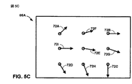
図5A〜図5Eは、本開示で説明する画像安定化技術に従って図3の画像キャプチャデバイス2などの画像キャプチャデバイスによってキャプチャされ、記憶され、画像プロセッサ6によって処理された例示的な画像66Aおよび66B(「画像66」)の図である。特に、画像センサ4は画像66をキャプチャし、画像66をバッファ26の各々に記憶することができる。画像情報66は2つの画像として示されているが、説明を簡単にするために、以下の説明の大部分では画像66Aを対象とする。ただし、説明は画像66Bに等しく適用可能である。
5A-5E are
ブロック分割器28は、画像66の一方または両方を画素の2つ以上のブロックに分割する。図5Aおよび図5Bの画像66Aに関して示すように、ブロック分割器28は画像情報をブロック68A〜68I(「ブロック68」)に分割する。図5Aおよび図5Bに示す例では、ブロック68は複数の重複ブロックである。しかしながら、本技術は重ならないブロック分割に適用できる。ブロック68への画像66Aの分割は2つの別々の図に示されているが、ブロック68は単一の画像66Aの分割である。言い換えれば、画像66Aは9つのブロックに分割される。例えば、図5Bのブロック68Fは図5Bのブロック68Iおよび68Gならびに図5Aのブロック68A、68Bおよび68Eに重なる。同様に、ブロック68Eは図5Aのブロック68A〜68Dおよび図5Bの68F〜68Iに重なる。ブロック分割器28は、場合によっては同様に画像66Bを分割することができる。
ブロック分割器28は、上述のいくつかの運動に対してぼけを低減できるようにし、ならびに計算の複雑さを減少させるために、この分割方式を選択することができる。例えば、ブロック分割器28は9つのブロックへの画像情報66Aの分割を選択することによって、水平および垂直(並進)運動に加えて、カメラとシーンの見通し線に接する回転、シーンへ向かう運動またはシーンから離れる運動によって生じるぼけをより容易に検出し、補正することができる。その上、ブロック分割方式は、さらにローリングシャッタを利用する画像キャプチャ技術に関連する運動の結果として生じる画像のぼけ、または他の視覚的アーティファクトを低減できるようにする。画像レジストレーションモジュール9は、ブロック中心70の散乱された性質のため、そのような動きを検出することができる。
The
動きベクトルモジュール32は、図5Cに示すようにそれぞれのブロック68の動きベクトル72A〜72I(「動きベクトル72」)を決定する。動きベクトルモジュール32は、上述のようにいくつかの技術のいずれかを使用してブロック68の各々について動きベクトル72を計算することができる。図5Cに示す例では、それぞれのブロックの動きベクトルは3×3の動きグリッドを形成する。しかしながら、上述のように本技術は2×2またはより大きいグリッドに適用可能である。
The motion vector module 32 determines the
動きベクトル72が決定されると、動きベクトル外挿器34および内挿器36は、それぞれ従来の外挿および内挿技術に従って動きベクトル72に基づいて図5Dおよび図5Eに示す動きベクトル74A〜74Kおよび76A〜76Lを外挿し、内挿する。説明しやすいように、外挿および内挿動きベクトル74および76のサブセットのみを示す。外挿および内挿動きベクトル74および76は、画像66内の画素の各行および列について計算できる。言い換えれば、動きベクトルモジュール32はブロックの各々内の画素の各々について動きベクトルを計算することができる。しかしながら、上述のように本技術を使用してブロックの画素のサブセット、例えばサブブロックのみについて動きベクトルを計算することができる。従って、本発明は図5Dおよび図5Eに示す動きベクトル72〜76の例に限定されるべきではない。
Once the motion vector 72 is determined, the
図5Dおよび図5Eに示す例では、動きベクトル外挿器34および内挿器36は、垂直動きベクトルに直線78Aおよび78Bを当てはめ(fit)(図5D)、水平動きベクトルに直線80を当てはめる(図5E)ことによって、直線補間および外挿を使用する。しかしながら、上述のように個々の画素について動きベクトルを計算するために、高次補間または外挿技術を使用することができる。従って、二次方程式、スプラインまたは他のタイプの直線当てはめアルゴリズムに従って直線を当てはめることができる。
In the example shown in FIGS. 5D and 5E,
本明細書で説明した技術は、ハードウェア、ソフトウェア、ファームウェア、またはそれらの任意の組合せで実施できる。モジュールまたは構成要素として説明するフィーチャは、集積論理デバイスに一緒に、または個別であるが相互運用可能な論理デバイスとして別々に実装できる。ソフトウェアで実装した場合、これらの技術は、実行されると、上記で説明した方法の1つまたは複数を実行する命令を備えるコンピュータ可読媒体によって少なくとも部分的に実現できる。コンピュータ可読媒体は、パッケージング材料を含むことがある、コンピュータプログラム製品の一部をなすことができる。コンピュータ可読媒体は、同期ダイナミックランダムアクセスメモリ(SDRAM)などのランダムアクセスメモリ(RAM)、読取り専用メモリ(ROM)、不揮発性ランダムアクセスメモリ(NVRAM)、電気消去可能プログラマブル読出し専用メモリ(EEPROM)、FLASHメモリ、磁気または光学データ記憶媒体などを備えることができる。本技術は、追加または代替として、命令またはデータ構造の形態でコードを搬送または伝達し、コンピュータによってアクセス、読込み、および/または実行できるコンピュータ可読通信媒体によって、少なくとも部分的に実現できる。 The techniques described herein may be implemented in hardware, software, firmware, or any combination thereof. Features described as modules or components can be implemented together in an integrated logical device or separately as a separate but interoperable logical device. When implemented in software, these techniques, when executed, can be implemented at least in part by a computer-readable medium comprising instructions that perform one or more of the methods described above. The computer readable medium may form part of a computer program product that may include packaging material. Computer readable media include random access memory (RAM) such as synchronous dynamic random access memory (SDRAM), read only memory (ROM), non-volatile random access memory (NVRAM), electrically erasable programmable read only memory (EEPROM), FLASH A memory, magnetic or optical data storage medium, etc. can be provided. The techniques can additionally or alternatively be implemented at least in part by a computer readable communication medium that carries or conveys code in the form of instructions or data structures and that can be accessed, read and / or executed by a computer.
コードは、1つまたは複数のDSP、汎用マイクロプロセッサ、ASIC、フィールドプログラマブル論理アレイFPGA、または他の等価な集積またはディスクリート論理回路など、1つまたは複数のプロセッサによって実行できる。従って、本明細書で使用する「プロセッサ」という用語は、前述の構造、または本明細書で説明する技術の実装に好適な他の構造のいずれかを指す。さらに、いくつかの態様では、本明細書で説明する機能を符号化および復号のために構成された専用のソフトウェアモジュールまたはハードウェアモジュール内に提供することができ、または複合ビデオエンコーダ/デコーダ(コーデック)に組み込むことができる。従って、本開示はまた、本開示で説明した技術の1つまたは複数を実装する回路を含む様々な集積回路デバイスのいずれかを企図する。そのような回路は、単一の集積回路チップまたは複数の相互運用可能な集積回路チップで提供できる。 The code may be executed by one or more processors, such as one or more DSPs, general purpose microprocessors, ASICs, field programmable logic arrays FPGAs, or other equivalent integrated or discrete logic circuits. Thus, as used herein, the term “processor” refers to either the structure described above or other structure suitable for implementation of the techniques described herein. Further, in some aspects, the functionality described herein may be provided in a dedicated software module or hardware module configured for encoding and decoding, or a composite video encoder / decoder (codec ). Accordingly, this disclosure also contemplates any of a variety of integrated circuit devices that include circuitry that implements one or more of the techniques described in this disclosure. Such a circuit can be provided in a single integrated circuit chip or multiple interoperable integrated circuit chips.
様々な技術について説明した。これらおよび他の例示的な態様は以下の特許請求の範囲の範囲内にある。
なお、以下に、出願当初の特許請求の範囲に記載された発明を付記する。
[C1]
関心シーンの第1画像を画素の複数のブロックに分割することと、
前記複数のブロックの各々について前記第1画像の前記ブロックと前記関心シーンの第2画像中の画素の対応するブロックとの間のオフセットを表す動きベクトルを計算することと、
前記画素が属する前記それぞれのブロックの前記動きベクトルに基づいて、前記第1画像の前記ブロックの前記画素の各々の画素値を前記第2画像の対応する画素の画素値で平均化することと、
前記平均化された画素値を記憶することと、
を具備するデジタル画像データの処理方法。
[C2]
前記複数のブロックの各々について、前記画素が属する前記ブロックについて計算された前記動きベクトルと前記画像の他の1つのブロックについて計算された少なくとも1つの他の動きベクトルとを使用して前記ブロックの前記画素の各々について動きベクトルを決定することをさらに具備し、
前記画素値を平均化することは、前記第1画像の前記ブロックの前記画素の各々の前記画素値を前記画素の前記それぞれの動きベクトルによって示される位置での前記第2画像の対応する画素の画素値で平均化することを含むC1に記載の方法。
[C3]
前記画素の各々について動きベクトルを決定することは、前記画素が属する前記ブロックについて計算された前記動きベクトルと前記画像の他の1つのブロックについて計算された少なくとも1つの他の動きベクトルとに基づいて、外挿と内挿のうちの1つを使用して前記画素の各々について動きベクトルを決定することを含むC2に記載の方法。
[C4]
前記複数のブロックの各々について、サブブロックが属する前記ブロックについて計算された前記動きベクトルと前記画像の他の1つのブロックについて計算された少なくとも1つの他の動きベクトルとを使用して前記ブロックの前記画素の前記サブブロックについて動きベクトルを決定することをさらに具備し、
前記画素値を平均化することは、前記第1画像の前記サブブロックの各々の前記画素値を前記サブブロックの前記それぞれの動きベクトルによって示される位置での前記第2画像の対応するサブブロックの画素値で平均化することを含むC1に記載の方法。
[C5]
動きベクトルを計算することは、
前記複数のブロックの各々について前記ブロックに対する水平投影と垂直投影とのうちの少なくとも1つを計算することと、
前記複数のブロックの各々について前記ブロックに対する前記水平および垂直投影のうちの前記少なくとも1つに基づいて動きベクトルを計算することと、
を含むC1に記載の方法。
[C6]
前記第1画像と前記第2画像とをキャプチャすることをさらに具備し、前記第1画像と前記第2画像とのうちの少なくとも1つが画像プレビュー中にキャプチャされるC1に記載の方法。
[C7]
前記第1画像を画素の複数のブロックに分割することは、前記第1画像を画素の複数の重複ブロックに分割することを含むC1に記載の方法。
[C8]
その上に命令を有するコンピュータ可読媒体を具備する、デジタル画像データを処理するためのコンピュータプログラム製品であって、前記命令は、
関心シーンの第1画像を画素の複数のブロックに分割するためのコードと、
前記複数のブロックの各々について前記第1画像の前記ブロックと前記関心シーンの第2画像中の画素の対応するブロックとの間のオフセットを表す動きベクトルを計算するためのコードと、
前記画素が属する前記それぞれのブロックの前記動きベクトルに基づいて前記第1画像の前記ブロックの前記画素の各々の画素値を前記第2画像の対応する画素の画素値で平均化するためのコードと、
前記平均化された画素値を記憶するためのコードと、
を具備するコンピュータプログラム製品。
[C9]
前記複数のブロックの各々について、前記画素が属する前記ブロックについて計算された前記動きベクトルと前記画像の他の1つのブロックについて計算された少なくとも1つの他の動きベクトルとを使用して前記ブロックの前記画素の各々について動きベクトルを決定するためのコードをさらに具備し、
前記画素値を平均化するためのコードは、前記第1画像の前記ブロックの前記画素の各々の前記画素値を前記画素の前記それぞれの動きベクトルによって示される位置での前記第2画像の対応する画素の画素値で平均化するためのコードを含むC8に記載のコンピュータプログラム製品。
[C10]
前記画素の各々について動きベクトルを決定するためのコードは、前記画素が属する前記ブロックについて計算された前記動きベクトルと前記画像の他の1つのブロックについて計算された少なくとも1つの他の動きベクトルとに基づいて、外挿と内挿のうちの1つを使用して前記画素の各々について動きベクトルを決定するためのコードを含むC9に記載のコンピュータプログラム製品。
[C11]
前記複数のブロックの各々について、サブブロックが属する前記ブロックについて計算された前記動きベクトルと前記画像の他の1つのブロックについて計算された少なくとも1つの他の動きベクトルとを使用して前記ブロックの前記画素の前記サブブロックについて動きベクトルを決定することをさらに具備し、
前記画素値を平均化することは、前記第1画像の前記サブブロックの各々の前記画素値を前記サブブロックの前記それぞれの動きベクトルによって示される位置での前記第2画像の対応するサブブロックの画素値で平均化することを含むC8に記載のコンピュータプログラム製品。
[C12]
動きベクトルを計算するためのコードは、
前記複数のブロックの各々について前記ブロックに対する水平投影と垂直投影とのうちの少なくとも1つを計算するためのコードと、
前記複数のブロックの各々について前記ブロックに対する前記水平および垂直投影のうちの前記少なくとも1つに基づいて動きベクトルを計算するためのコードとを含むC8に記載のコンピュータプログラム製品。
[C13]
前記第1画像と前記第2画像とをキャプチャするためのコードをさらに具備し、前記第1画像と前記第2画像とのうちの少なくとも1つが画像プレビュー中にキャプチャされるC8に記載のコンピュータプログラム製品。
[C14]
前記第1画像を分割するためのコードは、前記第1画像を画素の複数の重複ブロックに分割するためのコードを含むC8に記載のコンピュータプログラム製品。
[C15]
デジタル画像データを処理するための装置であって、
関心シーンの第1画像を画素の複数のブロックに分割するブロック分割器と、
前記複数のブロックの各々について前記第1画像の前記ブロックと前記関心シーンの第2画像中の画素の対応するブロックとの間のオフセットを表す動きベクトルを計算する動きベクトルモジュールと、
前記画素が属する前記それぞれのブロックの前記動きベクトルに基づいて前記第1画像の前記ブロックの前記画素の各々の画素値を前記第2画像の対応する画素の画素値で平均化する画素平均化モジュールと、を含む
前記画像データを処理する画像プロセッサと、
前記平均化された画素値を記憶するメモリと、
を具備する装置。
[C16]
前記動きベクトルモジュールは、前記複数のブロックの各々について、前記画素が属する前記ブロックについて計算された前記動きベクトルと前記画像の他の1つのブロックについて計算された少なくとも1つの他の動きベクトルとを使用して前記ブロックの前記画素の各々について動きベクトルを決定し、
前記画素平均化モジュールは、前記第1画像の前記ブロックの前記画素の各々の前記画素値を前記画素の前記それぞれの動きベクトルによって示される位置での前記第2画像の対応する画素の画素値で平均化する、C15に記載の装置。
[C17]
前記動きベクトルモジュールは、前記画素が属する前記ブロックについて計算された前記動きベクトルと前記画像の他の1つのブロックについて計算された少なくとも1つの他の動きベクトルとに基づいて、外挿と内挿のうちの1つを使用して前記画素の各々について動きベクトルを決定するC16に記載の装置。
[C18]
前記動きベクトルモジュールは、前記複数のブロックの各々について前記ブロックに対する水平投影と垂直投影とのうちの少なくとも1つを計算し、前記複数のブロックの各々について前記ブロックに対する前記水平および垂直投影のうちの前記少なくとも1つに基づく動きベクトルを計算するC15に記載の装置。
[C19]
前記第1画像と前記第2画像とをキャプチャする画像センサをさらに具備し、前記画像センサは画像プレビュー中に前記第1画像と前記第2画像とのうちの少なくとも1つをキャプチャするC15に記載の装置。
[C20]
前記ブロック分割器は、前記第1画像を画素の複数の重複ブロックに分割するC15に記載の装置。
[C21]
前記装置が無線通信デバイス内に組み込まれており、前記無線通信デバイスは、
前記平均化された画像を符号化する符号化モジュールと、
前記符号化画像を送信する送信機と、
を含むC15に記載の装置。
[C22]
関心シーンの第1画像を画素の複数のブロックに分割するための手段と、
前記複数のブロックの各々について、前記第1画像の前記ブロックと前記関心シーンの第2画像中の画素の対応するブロックとの間のオフセットを表す動きベクトルを計算するための手段と、
前記画素が属する前記それぞれのブロックの前記動きベクトルに基づいて前記第1画像の前記ブロックの前記画素の各々の画素値を前記第2画像の対応する画素の画素値で平均化するための手段と、
前記平均化された画素値を記憶するための手段と、
を具備するデジタル画像データを処理する装置。
[C23]
決定手段は、複数のブロックの各々について、前記画素が属する前記ブロックについて計算された前記動きベクトルと前記画像の他の1つのブロックについて計算された少なくとも1つの他の動きベクトルとを使用して前記ブロックの前記画素の各々について動きベクトルを決定し、
前記平均化手段は、前記第1画像の前記ブロックの前記画素の各々の前記画素値を前記画素の前記それぞれの動きベクトルによって示される位置での前記第2画像の対応する画素の画素値で平均化する、C22に記載の装置。
[C24]
前記決定手段は、前記画素が属する前記ブロックについて計算された前記動きベクトルと前記画像の他の1つのブロックについて計算された少なくとも1つの他の動きベクトルとに基づいて、外挿と内挿のうちの1つを使用して前記画素の各々について動きベクトルを決定するC23に記載の装置。
[C25]
前記決定手段は、前記複数のブロックの各々について、サブブロックが属する前記ブロックについて計算された前記動きベクトルと前記画像の他の1つのブロックについて計算された少なくとも1つの他の動きベクトルとを使用して前記ブロックの画素の前記サブブロックについて動きベクトルを決定し、
前記平均化手段は、前記第1画像の前記サブブロックの各々の前記画素値を前記サブブロックの前記それぞれの動きベクトルによって示される位置での前記第2画像の対応するサブブロックの画素値で平均化するC22に記載の装置。
Various techniques were explained. These and other exemplary embodiments are within the scope of the following claims.
In the following, the invention described in the scope of claims at the beginning of the application is appended.
[C1]
Dividing the first image of the scene of interest into a plurality of blocks of pixels;
Calculating a motion vector representing an offset between the block of the first image and the corresponding block of pixels in the second image of the scene of interest for each of the plurality of blocks;
Based on the motion vector of the respective block to which the pixel belongs, averaging each pixel value of the pixel of the block of the first image with the pixel value of the corresponding pixel of the second image;
Storing the averaged pixel values;
A method of processing digital image data.
[C2]
For each of the plurality of blocks, using the motion vector calculated for the block to which the pixel belongs and at least one other motion vector calculated for another block of the image Further comprising determining a motion vector for each of the pixels;
Averaging the pixel values means that the pixel value of each of the pixels of the block of the first image is equal to the corresponding pixel of the second image at the position indicated by the respective motion vector of the pixel. The method of C1, comprising averaging with pixel values.
[C3]
Determining a motion vector for each of the pixels is based on the motion vector calculated for the block to which the pixel belongs and at least one other motion vector calculated for another block of the image. The method of C2, comprising determining a motion vector for each of the pixels using one of extrapolation and interpolation.
[C4]
For each of the plurality of blocks, using the motion vector calculated for the block to which a sub-block belongs and at least one other motion vector calculated for another block of the image Further comprising determining a motion vector for the sub-block of pixels;
Averaging the pixel values means that the pixel values of each of the sub-blocks of the first image of the corresponding sub-block of the second image at the position indicated by the respective motion vector of the sub-block. The method of C1, comprising averaging with pixel values.
[C5]
Calculating the motion vector is
Calculating at least one of a horizontal projection and a vertical projection for each of the plurality of blocks;
Calculating a motion vector based on the at least one of the horizontal and vertical projections for the block for each of the plurality of blocks;
The method according to C1, comprising:
[C6]
The method of C1, further comprising capturing the first image and the second image, wherein at least one of the first image and the second image is captured during an image preview.
[C7]
The method of C1, wherein dividing the first image into a plurality of blocks of pixels includes dividing the first image into a plurality of overlapping blocks of pixels.
[C8]
A computer program product for processing digital image data comprising a computer readable medium having instructions thereon, wherein the instructions are
A code for dividing the first image of the scene of interest into a plurality of blocks of pixels;
Code for calculating a motion vector representing an offset between the block of the first image and the corresponding block of pixels in the second image of the scene of interest for each of the plurality of blocks;
A code for averaging each pixel value of the pixel of the block of the first image with a pixel value of a corresponding pixel of the second image based on the motion vector of the respective block to which the pixel belongs; ,
A code for storing the averaged pixel value;
A computer program product comprising:
[C9]
For each of the plurality of blocks, using the motion vector calculated for the block to which the pixel belongs and at least one other motion vector calculated for another block of the image Further comprising code for determining a motion vector for each of the pixels;
The code for averaging the pixel values corresponds to the second image at the position indicated by the respective motion vector of the pixel with the pixel value of each of the pixels of the block of the first image. The computer program product according to C8, which includes code for averaging with pixel values of pixels.
[C10]
The code for determining a motion vector for each of the pixels is in the motion vector calculated for the block to which the pixel belongs and at least one other motion vector calculated for another block of the image. A computer program product according to C9, comprising code for determining a motion vector for each of the pixels based on one of extrapolation and interpolation.
[C11]
For each of the plurality of blocks, using the motion vector calculated for the block to which a sub-block belongs and at least one other motion vector calculated for another block of the image Further comprising determining a motion vector for the sub-block of pixels;
Averaging the pixel values means that the pixel values of each of the sub-blocks of the first image of the corresponding sub-block of the second image at the position indicated by the respective motion vector of the sub-block. The computer program product according to C8, comprising averaging with pixel values.
[C12]
The code for calculating the motion vector is
Code for calculating at least one of a horizontal projection and a vertical projection for each of the plurality of blocks;
C8. The computer program product of C8, comprising: code for calculating a motion vector based on the at least one of the horizontal and vertical projections for the block for each of the plurality of blocks.
[C13]
The computer program according to C8, further comprising code for capturing the first image and the second image, wherein at least one of the first image and the second image is captured during an image preview. Product.
[C14]
The computer program product according to C8, wherein the code for dividing the first image includes a code for dividing the first image into a plurality of overlapping blocks of pixels.
[C15]
An apparatus for processing digital image data,
A block divider for dividing the first image of the scene of interest into a plurality of blocks of pixels;
A motion vector module for calculating a motion vector representing an offset between the block of the first image and the corresponding block of pixels in the second image of the scene of interest for each of the plurality of blocks;
A pixel averaging module that averages the pixel value of each pixel of the block of the first image with the pixel value of the corresponding pixel of the second image based on the motion vector of the respective block to which the pixel belongs And including
An image processor for processing the image data;
A memory for storing the averaged pixel values;
A device comprising:
[C16]
The motion vector module uses, for each of the plurality of blocks, the motion vector calculated for the block to which the pixel belongs and at least one other motion vector calculated for another block of the image. Determining a motion vector for each of the pixels of the block;
The pixel averaging module calculates the pixel value of each of the pixels of the block of the first image with the pixel value of the corresponding pixel of the second image at the position indicated by the respective motion vector of the pixel. The apparatus according to C15, averaging.
[C17]
The motion vector module may perform extrapolation and interpolation based on the motion vector calculated for the block to which the pixel belongs and at least one other motion vector calculated for another block of the image. The apparatus of C16, wherein a motion vector is determined for each of the pixels using one of them.
[C18]
The motion vector module calculates at least one of a horizontal projection and a vertical projection for the block for each of the plurality of blocks, and for each of the plurality of blocks, of the horizontal and vertical projections for the block The apparatus of C15, wherein a motion vector based on the at least one is calculated.
[C19]
C15 further comprising an image sensor that captures the first image and the second image, wherein the image sensor captures at least one of the first image and the second image during an image preview. Equipment.
[C20]
The apparatus according to C15, wherein the block divider divides the first image into a plurality of overlapping blocks of pixels.
[C21]
The apparatus is incorporated in a wireless communication device, the wireless communication device comprising:
An encoding module for encoding the averaged image;
A transmitter for transmitting the encoded image;
The apparatus according to C15, comprising:
[C22]
Means for dividing the first image of the scene of interest into a plurality of blocks of pixels;
Means for calculating, for each of the plurality of blocks, a motion vector representing an offset between the block of the first image and a corresponding block of pixels in a second image of the scene of interest;
Means for averaging the pixel value of each pixel of the block of the first image with the pixel value of the corresponding pixel of the second image based on the motion vector of the respective block to which the pixel belongs; ,
Means for storing the averaged pixel values;
A device for processing digital image data.
[C23]
The determining means uses, for each of a plurality of blocks, the motion vector calculated for the block to which the pixel belongs and at least one other motion vector calculated for another block of the image. Determining a motion vector for each of the pixels of the block;
The averaging means averages the pixel value of each of the pixels of the block of the first image with the pixel value of the corresponding pixel of the second image at the position indicated by the respective motion vector of the pixel. The device according to C22,
[C24]
The determining means includes extrapolation and interpolation based on the motion vector calculated for the block to which the pixel belongs and at least one other motion vector calculated for another block of the image. The apparatus of C23, wherein a motion vector is determined for each of the pixels using one of:
[C25]
The determining means uses, for each of the plurality of blocks, the motion vector calculated for the block to which a sub-block belongs and at least one other motion vector calculated for another block of the image. Determining a motion vector for the sub-block of pixels of the block,
The averaging means averages the pixel value of each of the sub-blocks of the first image with the pixel value of the corresponding sub-block of the second image at the position indicated by the respective motion vector of the sub-block. The apparatus according to C22.
Claims (26)
前記複数のブロックの各々について前記第1画像の前記ブロックと前記関心シーンの第2画像中の画素の対応するブロックとの間のオフセットを表す動きベクトルを計算することと、前記動きベクトルを計算することは、各画像の前記ブロックの各々について以下の式に従って水平および垂直投影を決定し、
以下の式に従って前記ブロックの動きベクトルを計算することを含む、
前記画素が属する前記それぞれのブロックの前記動きベクトルに基づいて、前記第1画像の前記ブロックの前記画素の各々の画素値を前記第2画像の対応する画素の画素値で平均化することと、
前記平均化された画素値を記憶することと、
を具備するデジタル画像を安定化する方法。 Dividing the first image of the scene of interest into a plurality of blocks of pixels;
Calculating a motion vector representing an offset between the block of the first image and a corresponding block of pixels in the second image of the scene of interest for each of the plurality of blocks; and calculating the motion vector Determines the horizontal and vertical projections for each of the blocks of each image according to the following equation:
Calculating a motion vector of the block according to the following equation:
Based on the motion vector of the respective block to which the pixel belongs, averaging each pixel value of the pixel of the block of the first image with the pixel value of the corresponding pixel of the second image;
Storing the averaged pixel values;
A method of stabilizing a digital image comprising:
前記画素値を平均化することは、前記第1画像の前記ブロックの前記画素の各々の前記画素値を前記画素の前記それぞれの動きベクトルによって示される位置での前記第2画像の対応する画素の画素値で平均化することを含む請求項1に記載の方法。 For each of the plurality of blocks, using the motion vector calculated for the block to which the pixel belongs and at least one other motion vector calculated for another block of the image Further comprising determining a motion vector for each of the pixels;
Averaging the pixel values means that the pixel value of each of the pixels of the block of the first image is equal to the corresponding pixel of the second image at the position indicated by the respective motion vector of the pixel. The method of claim 1 including averaging with pixel values.
前記画素値を平均化することは、前記第1画像の前記サブブロックの各々の前記画素値を前記サブブロックの前記それぞれの動きベクトルによって示される位置での前記第2画像の対応するサブブロックの画素値で平均化することを含む請求項1に記載の方法。 For each of the plurality of blocks, the block using the motion vector calculated for the block to which a sub-block belongs and at least one other motion vector calculated for another block of the first image Further determining a motion vector for the sub-block of the pixels of
Averaging the pixel values means that the pixel values of each of the sub-blocks of the first image of the corresponding sub-block of the second image at the position indicated by the respective motion vector of the sub-block. The method of claim 1 including averaging with pixel values.
前記複数のブロックの各々について前記ブロックに対する水平投影と垂直投影とのうちの少なくとも1つを計算することと、
前記複数のブロックの各々について前記ブロックに対する前記水平および垂直投影のうちの前記少なくとも1つに基づいて動きベクトルを計算することと、
を含む請求項1に記載の方法。 Calculating the motion vector is
Calculating at least one of a horizontal projection and a vertical projection for each of the plurality of blocks;
Calculating a motion vector based on the at least one of the horizontal and vertical projections for the block for each of the plurality of blocks;
The method of claim 1 comprising:
関心シーンの第1画像を画素の複数のブロックに分割させるためのコードと、
前記複数のブロックの各々について前記第1画像の前記ブロックと前記関心シーンの第2画像中の画素の対応するブロックとの間のオフセットを表す動きベクトルを計算させるためのコードと、前記コンピュータに前記動きベクトルを計算させることは、前記コンピュータに、各画像の前記ブロックの各々について以下の式に従って水平および垂直投影を決定させ、
以下の式に従って前記ブロックの動きベクトルを計算させるためのコードを含む、
前記画素が属する前記それぞれのブロックの前記動きベクトルに基づいて前記第1画像の前記ブロックの前記画素の各々の画素値を前記第2画像の対応する画素の画素値で平均化するためのコードと、
前記平均化された画素値を記憶するためのコードと、
を具備するコンピュータ読み取り可能記録媒体。 A computer readable recording medium comprising instructions for stabilizing a digital image storing instructions , wherein the instructions are
A code for dividing the first image of the scene of interest into a plurality of blocks of pixels;
Code for causing the computer to calculate a motion vector representing an offset between the block of the first image and the corresponding block of pixels in the second image of the scene of interest for each of the plurality of blocks; Letting the computer calculate the horizontal and vertical projections for each of the blocks of each image according to the following equation:
Including code for calculating the motion vector of the block according to the following equation:
A code for averaging each pixel value of the pixel of the block of the first image with a pixel value of a corresponding pixel of the second image based on the motion vector of the respective block to which the pixel belongs; ,
A code for storing the averaged pixel value;
A computer-readable recording medium comprising:
前記画素値を平均化するためのコードは、前記第1画像の前記ブロックの前記画素の各々の前記画素値を前記画素の前記それぞれの動きベクトルによって示される位置での前記第2画像の対応する画素の画素値で平均化するためのコードを含む請求項8に記載のコンピュータ読み取り可能記録媒体。 For each of the plurality of blocks, using the motion vector calculated for the block to which the pixel belongs and at least one other motion vector calculated for another block of the image Further comprising code for determining a motion vector for each of the pixels;
The code for averaging the pixel values corresponds to the second image at the position indicated by the respective motion vector of the pixel with the pixel value of each of the pixels of the block of the first image. The computer-readable recording medium according to claim 8, comprising a code for averaging with pixel values of pixels.
前記画素値を平均化することは、前記第1画像の前記サブブロックの各々の前記画素値を前記サブブロックの前記それぞれの動きベクトルによって示される位置での前記第2画像の対応するサブブロックの画素値で平均化することを含む請求項8に記載のコンピュータ読み取り可能記録媒体。 For each of the plurality of blocks, using the motion vector calculated for the block to which a sub-block belongs and at least one other motion vector calculated for another block of the image Further comprising determining a motion vector for the sub-block of pixels;
Averaging the pixel values means that the pixel values of each of the sub-blocks of the first image of the corresponding sub-block of the second image at the position indicated by the respective motion vector of the sub-block. The computer-readable recording medium according to claim 8, comprising averaging with pixel values.
前記複数のブロックの各々について前記ブロックに対する水平投影と垂直投影とのうちの少なくとも1つを計算するためのコードと、
前記複数のブロックの各々について前記ブロックに対する前記水平および垂直投影のうちの前記少なくとも1つに基づいて動きベクトルを計算するためのコードとを含む請求項8に記載のコンピュータ読み取り可能記録媒体。 The code for calculating the motion vector is
Code for calculating at least one of a horizontal projection and a vertical projection for each of the plurality of blocks;
9. The computer readable medium of claim 8, comprising code for calculating a motion vector based on the at least one of the horizontal and vertical projections for the block for each of the plurality of blocks.
関心シーンの第1画像を画素の複数のブロックに分割するブロック分割器と、
前記複数のブロックの各々について前記第1画像の前記ブロックと前記関心シーンの第2画像中の画素の対応するブロックとの間のオフセットを表す動きベクトルを計算する動きベクトルモジュールと、ここにおいて、前記動きベクトルモジュールは、各画像の前記ブロックの各々について以下の式に従って水平および垂直投影を決定し、
以下の式に従って前記ブロックの動きベクトルを計算する、
前記画素が属する前記それぞれのブロックの前記動きベクトルに基づいて前記第1画像の前記ブロックの前記画素の各々の画素値を前記第2画像の対応する画素の画素値で平均化する画素平均化モジュールと、を含む
画像データを処理する画像プロセッサと、
前記平均化された画素値を記憶するメモリと、
を具備する装置。 An apparatus for stabilizing a digital image,
A block divider for dividing the first image of the scene of interest into a plurality of blocks of pixels;
A motion vector module for calculating a motion vector representing an offset between the block of the first image and the corresponding block of pixels in the second image of the scene of interest for each of the plurality of blocks, wherein The motion vector module determines horizontal and vertical projections for each of the blocks of each image according to the following equations:
Calculate the motion vector of the block according to the following equation:
A pixel averaging module that averages the pixel value of each pixel of the block of the first image with the pixel value of the corresponding pixel of the second image based on the motion vector of the respective block to which the pixel belongs And an image processor for processing image data including:
A memory for storing the averaged pixel values;
A device comprising:
前記画素平均化モジュールは、前記第1画像の前記ブロックの前記画素の各々の前記画素値を前記画素の前記それぞれの動きベクトルによって示される位置での前記第2画像の対応する画素の画素値で平均化する、請求項15に記載の装置。 The motion vector module, for each of the plurality of blocks, the motion vector calculated for the block to which the pixel belongs and at least one other motion vector calculated for another block of the first image; Determine a motion vector for each of the pixels of the block using
The pixel averaging module calculates the pixel value of each of the pixels of the block of the first image with the pixel value of the corresponding pixel of the second image at the position indicated by the respective motion vector of the pixel. The apparatus of claim 15, averaging.
前記平均化された画像を符号化する符号化モジュールと、
符号化画像を送信する送信機と、
を含む請求項15に記載の装置。 The apparatus is incorporated in a wireless communication device, the wireless communication device comprising:
An encoding module for encoding the averaged image;
A transmitter for transmitting an encoded image;
The apparatus of claim 15 comprising:
前記関心シーンの第2画像を画素の第2の複数の対応するブロックに分割するための手段と、
以下の式に従って前記第1および第2の複数のブロックの各々について水平および垂直投影を決定するための手段と、
以下の式に従って前記第2の複数のブロックにおける対応するブロックに基づいて、前記第1の複数のブロックの各々について動きベクトルを計算するための手段を含む、
前記画素が属する前記それぞれのブロックの前記動きベクトルに基づいて前記第1画像の前記ブロックの前記画素の各々の画素値を前記第2画像の対応する画素の画素値で平均化するための手段と、
前記平均化された画素値を記憶するための手段と、
を具備するデジタル画像を安定化する装置。 Means for dividing the first image of the scene of interest into a first plurality of blocks of pixels;
Means for dividing the second image of the scene of interest into a second plurality of corresponding blocks of pixels;
Means for determining horizontal and vertical projections for each of the first and second plurality of blocks according to the following equation:
Means for calculating a motion vector for each of the first plurality of blocks based on corresponding blocks in the second plurality of blocks according to the following equation:
Means for averaging the pixel value of each pixel of the block of the first image with the pixel value of the corresponding pixel of the second image based on the motion vector of the respective block to which the pixel belongs; ,
Means for storing the averaged pixel values;
An apparatus for stabilizing a digital image comprising:
画素値を前記平均化するための手段は、前記第1画像の前記第1の複数のブロックの前記画素の各々の前記画素値を前記画素の前記それぞれの動きベクトルによって示される位置での前記第2画像の前記第2の複数のブロックの対応する画素の画素値で平均化する、請求項22に記載の装置。 Based on at least one other motion vector computed for one other block of said motion vector calculated for the block in the first plurality of blocks before Symbol pixel belongs first plurality of blocks Means for determining a motion vector for each pixel in the first plurality of blocks ,
The means for averaging pixel values includes calculating the pixel values of each of the pixels of the first plurality of blocks of the first image at the positions indicated by the respective motion vectors of the pixels. 23. The apparatus of claim 22, wherein averaging is performed with pixel values of corresponding pixels of the second plurality of blocks of two images.
画素値を前記平均化するための手段は、前記第1画像の前記サブブロックの各々の前記画素値を前記サブブロックの前記それぞれの動きベクトルによって示される位置での前記第2画像の対応するサブブロックの画素値で平均化する請求項22に記載の装置。 Based on said at least one other motion vector subblock is calculated for the other one block of the first plurality of blocks of said motion vector computed for the block belonging to the first image first Means for determining a motion vector for a sub- block of pixels in the plurality of blocks ,
The means for averaging the pixel values is obtained by assigning the pixel value of each of the sub-blocks of the first image to a corresponding sub-position of the second image at the position indicated by the respective motion vector of the sub-block. The apparatus of claim 22, wherein the averaging is performed on the pixel values of the block.
Applications Claiming Priority (2)
| Application Number | Priority Date | Filing Date | Title |
|---|---|---|---|
| US11/938,711 | 2007-11-12 | ||
| US11/938,711 US8600189B2 (en) | 2007-11-12 | 2007-11-12 | Block-based image stabilization |
Related Parent Applications (1)
| Application Number | Title | Priority Date | Filing Date |
|---|---|---|---|
| JP2010534150A Division JP2011504266A (en) | 2007-11-12 | 2008-11-12 | Block-based image stabilization |
Publications (2)
| Publication Number | Publication Date |
|---|---|
| JP2014143702A JP2014143702A (en) | 2014-08-07 |
| JP5908511B2 true JP5908511B2 (en) | 2016-04-26 |
Family
ID=40030322
Family Applications (2)
| Application Number | Title | Priority Date | Filing Date |
|---|---|---|---|
| JP2010534150A Withdrawn JP2011504266A (en) | 2007-11-12 | 2008-11-12 | Block-based image stabilization |
| JP2014043056A Active JP5908511B2 (en) | 2007-11-12 | 2014-03-05 | Block-based image stabilization |
Family Applications Before (1)
| Application Number | Title | Priority Date | Filing Date |
|---|---|---|---|
| JP2010534150A Withdrawn JP2011504266A (en) | 2007-11-12 | 2008-11-12 | Block-based image stabilization |
Country Status (7)
| Country | Link |
|---|---|
| US (1) | US8600189B2 (en) |
| EP (1) | EP2058760B1 (en) |
| JP (2) | JP2011504266A (en) |
| KR (1) | KR101154087B1 (en) |
| CN (1) | CN101896935A (en) |
| TW (1) | TW200931343A (en) |
| WO (1) | WO2009064810A1 (en) |
Families Citing this family (38)
| Publication number | Priority date | Publication date | Assignee | Title |
|---|---|---|---|---|
| US7970239B2 (en) | 2006-01-19 | 2011-06-28 | Qualcomm Incorporated | Hand jitter reduction compensating for rotational motion |
| US8120658B2 (en) * | 2006-01-19 | 2012-02-21 | Qualcomm Incorporated | Hand jitter reduction system for cameras |
| US8019179B2 (en) * | 2006-01-19 | 2011-09-13 | Qualcomm Incorporated | Hand jitter reduction for compensating for linear displacement |
| US20090201427A1 (en) * | 2008-02-12 | 2009-08-13 | Brian Heng | Method and system for pixel adaptive weighted median filtering for block motion vector decomposition |
| KR100939917B1 (en) | 2008-03-07 | 2010-02-03 | 에스케이 텔레콤주식회사 | Encoding system using motion estimation and encoding method using motion estimation |
| US20100103323A1 (en) * | 2008-10-24 | 2010-04-29 | Ati Technologies Ulc | Method, apparatus and software for determining motion vectors |
| CN102752585B (en) * | 2011-04-18 | 2015-04-15 | 联咏科技股份有限公司 | Data processing method and digital image processing device |
| US8941751B2 (en) | 2011-05-06 | 2015-01-27 | Empire Technology Development Llc | Higher resolution still image generation from lower resolution video camera frames |
| JP2012242563A (en) * | 2011-05-18 | 2012-12-10 | Pentax Ricoh Imaging Co Ltd | Camera shake correction device and digital camera |
| US8385732B2 (en) | 2011-07-29 | 2013-02-26 | Hewlett-Packard Development Company, L.P. | Image stabilization |
| US8675997B2 (en) | 2011-07-29 | 2014-03-18 | Hewlett-Packard Development Company, L.P. | Feature based image registration |
| CN102509255B (en) * | 2011-10-26 | 2014-03-26 | 苏州百滨电子科技有限公司 | High-speed image acquiring and processing method and device |
| TWI469062B (en) | 2011-11-11 | 2015-01-11 | Ind Tech Res Inst | Image stabilization method and image stabilization device |
| KR101804215B1 (en) * | 2012-03-06 | 2017-12-05 | 삼성전자주식회사 | A method and an apparatus for estimating a non-uniform motion blur robustly |
| CN102637295B (en) * | 2012-03-31 | 2014-07-23 | 北京智安邦科技有限公司 | Rapid electronic image-stabilizing method and device |
| ITVI20120087A1 (en) | 2012-04-17 | 2013-10-18 | St Microelectronics Srl | DIGITAL VIDEO STABILIZATION |
| US8842910B2 (en) * | 2012-08-17 | 2014-09-23 | Tandent Vision Science, Inc. | Spatially varying log-chromaticity normals for use in an image process |
| US8446481B1 (en) | 2012-09-11 | 2013-05-21 | Google Inc. | Interleaved capture for high dynamic range image acquisition and synthesis |
| KR102003671B1 (en) * | 2012-10-29 | 2019-07-25 | 삼성전자주식회사 | Method and apparatus for processing the image |
| US8866927B2 (en) | 2012-12-13 | 2014-10-21 | Google Inc. | Determining an image capture payload burst structure based on a metering image capture sweep |
| US9087391B2 (en) | 2012-12-13 | 2015-07-21 | Google Inc. | Determining an image capture payload burst structure |
| US8866928B2 (en) | 2012-12-18 | 2014-10-21 | Google Inc. | Determining exposure times using split paxels |
| US9247152B2 (en) | 2012-12-20 | 2016-01-26 | Google Inc. | Determining image alignment failure |
| US8995784B2 (en) | 2013-01-17 | 2015-03-31 | Google Inc. | Structure descriptors for image processing |
| US9686537B2 (en) | 2013-02-05 | 2017-06-20 | Google Inc. | Noise models for image processing |
| US9117134B1 (en) | 2013-03-19 | 2015-08-25 | Google Inc. | Image merging with blending |
| US9066017B2 (en) | 2013-03-25 | 2015-06-23 | Google Inc. | Viewfinder display based on metering images |
| US9077913B2 (en) | 2013-05-24 | 2015-07-07 | Google Inc. | Simulating high dynamic range imaging with virtual long-exposure images |
| US9131201B1 (en) | 2013-05-24 | 2015-09-08 | Google Inc. | Color correcting virtual long exposures with true long exposures |
| US9615012B2 (en) | 2013-09-30 | 2017-04-04 | Google Inc. | Using a second camera to adjust settings of first camera |
| US9478010B2 (en) | 2013-12-12 | 2016-10-25 | Google Technology Holdings LLC | Generating an enhanced image of a predetermined scene from a plurality of images of the predetermined |
| US20150237351A1 (en) * | 2014-02-18 | 2015-08-20 | Penne Lee | Techniques for inclusion of region of interest indications in compressed video data |
| JP6336341B2 (en) * | 2014-06-24 | 2018-06-06 | キヤノン株式会社 | Imaging apparatus, control method therefor, program, and storage medium |
| CN104363380B (en) * | 2014-10-15 | 2017-10-27 | 北京智谷睿拓技术服务有限公司 | IMAQ control method and device |
| WO2018132760A1 (en) * | 2017-01-13 | 2018-07-19 | Warner Bros. Entertainment, Inc. | Adding motion effects to digital still images |
| US10491832B2 (en) | 2017-08-16 | 2019-11-26 | Qualcomm Incorporated | Image capture device with stabilized exposure or white balance |
| CN108898615B (en) * | 2018-06-15 | 2021-09-24 | 阿依瓦(北京)技术有限公司 | Block matching method for high frequency information image |
| US10595000B1 (en) | 2018-08-02 | 2020-03-17 | Facebook Technologies, Llc | Systems and methods for using depth information to extrapolate two-dimentional images |
Family Cites Families (30)
| Publication number | Priority date | Publication date | Assignee | Title |
|---|---|---|---|---|
| JP2687974B2 (en) | 1986-03-31 | 1997-12-08 | 日本放送協会 | Motion vector detection method |
| JP3103894B2 (en) * | 1991-02-06 | 2000-10-30 | ソニー株式会社 | Apparatus and method for correcting camera shake of video data |
| US5943096A (en) * | 1995-03-24 | 1999-08-24 | National Semiconductor Corporation | Motion vector based frame insertion process for increasing the frame rate of moving images |
| JP2798120B2 (en) | 1995-08-04 | 1998-09-17 | 日本電気株式会社 | Motion compensated interframe prediction method and motion compensated interframe prediction device |
| JP2798035B2 (en) * | 1996-01-17 | 1998-09-17 | 日本電気株式会社 | Motion compensated inter-frame prediction method using adaptive motion vector interpolation |
| JPH11331833A (en) * | 1998-05-15 | 1999-11-30 | Hitachi Ltd | Wide visual field monitoring camera system |
| US6130912A (en) * | 1998-06-09 | 2000-10-10 | Sony Electronics, Inc. | Hierarchical motion estimation process and system using block-matching and integral projection |
| JP4294881B2 (en) * | 2000-05-12 | 2009-07-15 | 富士フイルム株式会社 | Image registration method and apparatus |
| JP2004343483A (en) | 2003-05-16 | 2004-12-02 | Acutelogic Corp | Device and method for correcting camera-shake and device for detecting camera shake |
| DE102004017145B4 (en) * | 2004-04-07 | 2006-02-16 | Micronas Gmbh | Method and device for determining motion vectors associated with image areas of an image |
| JP4419675B2 (en) * | 2004-05-14 | 2010-02-24 | ソニー株式会社 | Solid-state imaging device and driving method of solid-state imaging device |
| JP2008515347A (en) * | 2004-09-29 | 2008-05-08 | ワーナー ブロス.エンターテイメント,インク. | Component image blotch correction |
| KR100588132B1 (en) * | 2004-10-04 | 2006-06-09 | 삼성전자주식회사 | Display apparatus |
| US7847823B2 (en) * | 2005-01-14 | 2010-12-07 | Morpho, Inc. | Motion vector calculation method and hand-movement correction device, imaging device and moving picture generation device |
| US8482618B2 (en) * | 2005-02-22 | 2013-07-09 | Hewlett-Packard Development Company, L.P. | Reduction of motion-induced blur in images |
| KR100699261B1 (en) | 2005-06-24 | 2007-03-27 | 삼성전자주식회사 | Motion Error Detector, Motion Error Compensator Comprising The Same, Method for Detecting Motion Error and Method for Compensating Motion Error |
| JP4595733B2 (en) * | 2005-08-02 | 2010-12-08 | カシオ計算機株式会社 | Image processing device |
| KR100714698B1 (en) * | 2005-08-29 | 2007-05-07 | 삼성전자주식회사 | Enhanced motion estimation method, video encoding method and apparatus using the same |
| WO2007032082A1 (en) * | 2005-09-16 | 2007-03-22 | Fujitsu Limited | Image processing method, and image processing device |
| KR100721543B1 (en) * | 2005-10-11 | 2007-05-23 | (주) 넥스트칩 | A method for removing noise in image using statistical information and a system thereof |
| EP1949338A1 (en) * | 2005-10-12 | 2008-07-30 | Active Optics Pty Ltd. | Image processing method and system |
| WO2007063675A1 (en) | 2005-11-30 | 2007-06-07 | Nikon Corporation | Image processing method, image processing program, image processing device, and imaging device |
| JP4304528B2 (en) * | 2005-12-01 | 2009-07-29 | ソニー株式会社 | Image processing apparatus and image processing method |
| JP4528255B2 (en) * | 2005-12-06 | 2010-08-18 | 日本放送協会 | Video decoding apparatus and video decoding program |
| US20070171981A1 (en) * | 2006-01-25 | 2007-07-26 | Yingyong Qi | Projection based techniques and apparatus that generate motion vectors used for video stabilization and encoding |
| JP2007257287A (en) * | 2006-03-23 | 2007-10-04 | Tokyo Institute Of Technology | Image registration method |
| US8306280B2 (en) * | 2006-04-11 | 2012-11-06 | Nikon Corporation | Electronic camera and image processing apparatus |
| JP2007282119A (en) | 2006-04-11 | 2007-10-25 | Nikon Corp | Electronic camera and image processing apparatus |
| US7746934B2 (en) * | 2006-04-19 | 2010-06-29 | Nethra Imaging Inc. | Image stabilization method |
| EP1892666A1 (en) * | 2006-08-16 | 2008-02-27 | Toyota Motor Europe NV | A method, an apparatus and a computer-readable medium for processing an image dataset |
-
2007
- 2007-11-12 US US11/938,711 patent/US8600189B2/en active Active
-
2008
- 2008-03-31 EP EP08006425.6A patent/EP2058760B1/en not_active Not-in-force
- 2008-11-12 WO PCT/US2008/083275 patent/WO2009064810A1/en active Application Filing
- 2008-11-12 CN CN2008801206288A patent/CN101896935A/en active Pending
- 2008-11-12 JP JP2010534150A patent/JP2011504266A/en not_active Withdrawn
- 2008-11-12 KR KR1020107013098A patent/KR101154087B1/en active IP Right Grant
- 2008-11-12 TW TW097143700A patent/TW200931343A/en unknown
-
2014
- 2014-03-05 JP JP2014043056A patent/JP5908511B2/en active Active
Also Published As
| Publication number | Publication date |
|---|---|
| WO2009064810A1 (en) | 2009-05-22 |
| KR20100092017A (en) | 2010-08-19 |
| KR101154087B1 (en) | 2012-06-11 |
| TW200931343A (en) | 2009-07-16 |
| EP2058760B1 (en) | 2018-08-08 |
| EP2058760A1 (en) | 2009-05-13 |
| JP2014143702A (en) | 2014-08-07 |
| JP2011504266A (en) | 2011-02-03 |
| US20090123082A1 (en) | 2009-05-14 |
| CN101896935A (en) | 2010-11-24 |
| US8600189B2 (en) | 2013-12-03 |
Similar Documents
| Publication | Publication Date | Title |
|---|---|---|
| JP5908511B2 (en) | Block-based image stabilization | |
| US9288392B2 (en) | Image capturing device capable of blending images and image processing method for blending images thereof | |
| US9432579B1 (en) | Digital image processing | |
| US7773115B2 (en) | Method and system for deblurring digital camera images using reference image and motion estimation | |
| KR101027353B1 (en) | Electronic video image stabilization | |
| KR101352730B1 (en) | System and method to selectively combine video frame image data | |
| JP5226794B2 (en) | Motion-assisted image sensor configuration | |
| US8581992B2 (en) | Image capturing apparatus and camera shake correction method, and computer-readable medium | |
| US8179446B2 (en) | Video stabilization and reduction of rolling shutter distortion | |
| US8098957B2 (en) | Shared block comparison architechture for image registration and video coding | |
| US9113059B2 (en) | Image pickup apparatus and image region discrimination method | |
| KR100793284B1 (en) | Apparatus for digital image stabilizing, method using the same and computer readable medium stored thereon computer executable instruction for performing the method | |
| JP5882702B2 (en) | Imaging device | |
| JP2011171842A (en) | Image processor and image processing program | |
| JP6603557B2 (en) | Image processing apparatus and image processing method | |
| JP2011244028A (en) | Imaging apparatus, shake correcting method, and program | |
| JP5854801B2 (en) | Image processing apparatus, image processing method, and program | |
| JP2012070337A (en) | Image processor, imaging apparatus, and image processing program |
Legal Events
| Date | Code | Title | Description |
|---|---|---|---|
| A977 | Report on retrieval |
Free format text: JAPANESE INTERMEDIATE CODE: A971007 Effective date: 20150209 |
|
| A131 | Notification of reasons for refusal |
Free format text: JAPANESE INTERMEDIATE CODE: A131 Effective date: 20150303 |
|
| A601 | Written request for extension of time |
Free format text: JAPANESE INTERMEDIATE CODE: A601 Effective date: 20150603 |
|
| A521 | Request for written amendment filed |
Free format text: JAPANESE INTERMEDIATE CODE: A523 Effective date: 20150901 |
|
| TRDD | Decision of grant or rejection written | ||
| A01 | Written decision to grant a patent or to grant a registration (utility model) |
Free format text: JAPANESE INTERMEDIATE CODE: A01 Effective date: 20160223 |
|
| A61 | First payment of annual fees (during grant procedure) |
Free format text: JAPANESE INTERMEDIATE CODE: A61 Effective date: 20160323 |
|
| R150 | Certificate of patent or registration of utility model |
Ref document number: 5908511 Country of ref document: JP Free format text: JAPANESE INTERMEDIATE CODE: R150 |
|
| R250 | Receipt of annual fees |
Free format text: JAPANESE INTERMEDIATE CODE: R250 |
|
| R250 | Receipt of annual fees |
Free format text: JAPANESE INTERMEDIATE CODE: R250 |
|
| R250 | Receipt of annual fees |
Free format text: JAPANESE INTERMEDIATE CODE: R250 |
|
| R250 | Receipt of annual fees |
Free format text: JAPANESE INTERMEDIATE CODE: R250 |
|
| R250 | Receipt of annual fees |
Free format text: JAPANESE INTERMEDIATE CODE: R250 |