JP5906484B2 - Disc image acquisition device and disc sorting device - Google Patents
Disc image acquisition device and disc sorting device Download PDFInfo
- Publication number
- JP5906484B2 JP5906484B2 JP2011252431A JP2011252431A JP5906484B2 JP 5906484 B2 JP5906484 B2 JP 5906484B2 JP 2011252431 A JP2011252431 A JP 2011252431A JP 2011252431 A JP2011252431 A JP 2011252431A JP 5906484 B2 JP5906484 B2 JP 5906484B2
- Authority
- JP
- Japan
- Prior art keywords
- imaging
- medal
- image
- disk
- disc
- Prior art date
- Legal status (The legal status is an assumption and is not a legal conclusion. Google has not performed a legal analysis and makes no representation as to the accuracy of the status listed.)
- Active
Links
- 238000003384 imaging method Methods 0.000 claims description 210
- 238000001514 detection method Methods 0.000 claims description 58
- 230000002093 peripheral effect Effects 0.000 claims description 17
- 238000000034 method Methods 0.000 description 67
- 230000008569 process Effects 0.000 description 64
- 238000012545 processing Methods 0.000 description 24
- 238000006243 chemical reaction Methods 0.000 description 15
- 230000008602 contraction Effects 0.000 description 14
- 238000003780 insertion Methods 0.000 description 13
- 230000037431 insertion Effects 0.000 description 13
- 238000000605 extraction Methods 0.000 description 12
- 238000007781 pre-processing Methods 0.000 description 11
- 238000005096 rolling process Methods 0.000 description 9
- 238000009792 diffusion process Methods 0.000 description 8
- 230000003287 optical effect Effects 0.000 description 8
- 230000008901 benefit Effects 0.000 description 7
- 230000001965 increasing effect Effects 0.000 description 6
- 238000011144 upstream manufacturing Methods 0.000 description 5
- 238000010586 diagram Methods 0.000 description 4
- 239000011347 resin Substances 0.000 description 4
- 229920005989 resin Polymers 0.000 description 4
- PXFBZOLANLWPMH-UHFFFAOYSA-N 16-Epiaffinine Natural products C1C(C2=CC=CC=C2N2)=C2C(=O)CC2C(=CC)CN(C)C1C2CO PXFBZOLANLWPMH-UHFFFAOYSA-N 0.000 description 3
- 239000008186 active pharmaceutical agent Substances 0.000 description 3
- 230000007547 defect Effects 0.000 description 3
- 238000005286 illumination Methods 0.000 description 3
- 230000009467 reduction Effects 0.000 description 3
- 230000009466 transformation Effects 0.000 description 3
- 238000013519 translation Methods 0.000 description 3
- VYZAMTAEIAYCRO-UHFFFAOYSA-N Chromium Chemical compound [Cr] VYZAMTAEIAYCRO-UHFFFAOYSA-N 0.000 description 2
- 229910052804 chromium Inorganic materials 0.000 description 2
- 239000011651 chromium Substances 0.000 description 2
- 238000007429 general method Methods 0.000 description 2
- 239000011521 glass Substances 0.000 description 2
- 238000009434 installation Methods 0.000 description 2
- 239000000463 material Substances 0.000 description 2
- BQCADISMDOOEFD-UHFFFAOYSA-N Silver Chemical compound [Ag] BQCADISMDOOEFD-UHFFFAOYSA-N 0.000 description 1
- 230000008859 change Effects 0.000 description 1
- 239000003086 colorant Substances 0.000 description 1
- 238000012937 correction Methods 0.000 description 1
- 230000007423 decrease Effects 0.000 description 1
- 230000003247 decreasing effect Effects 0.000 description 1
- 238000000151 deposition Methods 0.000 description 1
- 230000000694 effects Effects 0.000 description 1
- 230000002708 enhancing effect Effects 0.000 description 1
- 239000000284 extract Substances 0.000 description 1
- 239000004973 liquid crystal related substance Substances 0.000 description 1
- 230000002265 prevention Effects 0.000 description 1
- 230000008439 repair process Effects 0.000 description 1
- 230000004044 response Effects 0.000 description 1
- 230000000717 retained effect Effects 0.000 description 1
- 230000035945 sensitivity Effects 0.000 description 1
- 229910052709 silver Inorganic materials 0.000 description 1
- 239000004332 silver Substances 0.000 description 1
- 239000000758 substrate Substances 0.000 description 1
Images


Landscapes
- Testing Of Coins (AREA)
Description
本発明は、ディスク画像取得装置に関し、詳しくは、ディスクの表面または裏面に形成された模様を撮像して撮像画像を取得するディスク画像取得装置に関する。さらに詳しくは、直径の異なる複数種類のディスクに対しても容易かつ確実に画像を取得できるディスク画像取得装置に関する。 The present invention relates to a disk image acquisition apparatus, and more particularly to a disk image acquisition apparatus that acquires a captured image by imaging a pattern formed on the front surface or the back surface of a disk. More specifically, the present invention relates to a disc image acquisition device that can easily and reliably acquire images from a plurality of types of discs having different diameters.
また、本発明は、ディスク選別装置に関し、詳しくは、ディスクの表面または裏面に形成された模様を撮像して撮像画像を取得し、当該撮像画像を基準画像と比較することによりディスクの真偽を判別し、当該判別結果に基づいてディスクを選別するディスク選別装置に関する。さらに詳しくは、直径の異なる複数種類のディスクに対しても容易かつ確実に画像を取得して選別できるディスク選別装置に関する。 The present invention also relates to a disk sorting device, and more specifically, captures a pattern formed on the front surface or the back surface of the disk to acquire a captured image, and compares the captured image with a reference image to determine the authenticity of the disk. The present invention relates to a disc sorting device that discriminates and sorts discs based on the discrimination result. More specifically, the present invention relates to a disk sorting apparatus that can easily and reliably acquire and sort images of a plurality of types of disks having different diameters.
なお、本明細書におけるディスクは、通貨である硬貨、遊技機に用いられるメダルやトークンをも含む概念である。 The disc in this specification is a concept including coins as currency, medals and tokens used for gaming machines.
従来より、硬貨やメダル等のディスクの表面または裏面(以下、ディスク表面という)に形成された模様をイメージセンサにより撮像し、撮像画像を用いて真偽や金種を判別する装置が提案されており、特に移動するディスクを撮像する場合には、ディスクが撮像位置に到達したことをタイミングセンサにより検知し、タイミングセンサの検知出力に基づいてディスクを撮像している。 2. Description of the Related Art Conventionally, there has been proposed an apparatus for picking up a pattern formed on the front or back surface of a disc such as coins or medals (hereinafter referred to as a disc surface) with an image sensor and discriminating the authenticity or denomination using the captured image. In particular, when imaging a moving disk, the timing sensor detects that the disk has reached the imaging position, and images the disk based on the detection output of the timing sensor.
例えば、特許文献1には、撮像位置に対し硬貨の移動方向上流側に配置された第1センサが硬貨の通過を検出したとき、硬貨が撮像位置に達する以前に予めイメージセンサの撮像動作を開始し、第2センサが硬貨の撮像位置への到達を検出したとき、照明を短時間照射してイメージセンサにより硬貨表面の撮像画像を取得する硬貨識別装置が開示されている。
For example, in
特許文献2には、撮像位置に対し硬貨の移動方向下流側に配置された硬貨検知センサにより硬貨の先端の到来を検知し、硬貨検知センサの検知に同期して硬貨の表面に光を照射してイメージセンサにより硬貨の外周を含む画像を取得する硬貨識別装置が開示されている。
In
特許文献3には、発光素子から照射された光が硬貨の到来によって遮断されたことを受光素子により検知して硬貨到来時刻を撮像タイミング決定手段に通知し、撮像タイミング決定手段が硬貨到来時刻と硬貨の撮像位置および硬貨搬送速度から撮像タイミングを算出し、制御部がそのタイミングで硬貨の所定位置の画像を撮像するよう撮像手段に指令する硬貨画像識別装置が開示されている。
In
特許文献4には、硬貨搬送方向上流側の異なる位置に複数の硬貨位置検出器を配置し、硬貨の大きさに応じて複数の硬貨位置検出器を選択的に作動させるワーク画像認識装置が開示されている。
ところで、硬貨やメダル等のディスクには直径の異なる複数の種類があり、ディスク表面に形成された模様の撮像画像を取得するディスク画像取得装置には、直径の異なるディスクであってもディスク表面の模様全体を含む撮像画像を取得することが求められる。これは、模様の一部が撮像されないと模様の判別精度が低下するからである。 By the way, there are a plurality of types of discs such as coins and medals having different diameters, and a disc image acquisition device for acquiring a captured image of a pattern formed on the disc surface has a disk surface of different diameters. It is required to acquire a captured image including the entire pattern. This is because the pattern discrimination accuracy decreases if a part of the pattern is not captured.
上記特許文献1の硬貨識別装置では、直径の異なる硬貨への対応については何ら考慮されておらず、硬貨の直径が変わると撮像領域における硬貨の中心位置が硬貨の移動方向上流側にシフトしてしまう。そのため、小径硬貨に合わせて撮像領域を設定した場合、シフト量の大きい大径硬貨において模様が撮像領域からはみ出てしまう。換言すれば、判別できる硬貨の直径範囲が小さいという問題がある。他方、大径硬貨に合わせて撮像領域を拡大した場合、イメージセンサや照明装置が大型となり、コストアップや装置全体が大型化するという問題がある。画角の広いレンズを用いればイメージセンサを大型化する必要はないが、照明装置の大型化は避けられない。さらに、硬貨の直径により中心位置が変わるため、画像判別の基準となる硬貨の中心位置を求める際に、硬貨の外周を検出して中心位置を求めるという一般的な方法が適用されるため、画像判別に要する処理時間が長くなるという問題もある。
In the coin identification device of
特許文献2の硬貨識別装置の場合、直径の異なる硬貨を想定しているものの、硬貨表面の周縁部を撮像する装置であり、硬貨表面の模様全体の画像を取得する場合については何ら考慮されていない。そして、硬貨の先端を硬貨検知センサにより検知するため、硬貨の直径が変わると撮像領域における硬貨の中心位置が硬貨の移動方向上流側にシフトする。したがって、特許文献1の硬貨識別装置と同様の問題がある。
In the case of the coin discriminating apparatus of
特許文献3の硬貨画像識別装置では、硬貨の撮像位置および硬貨搬送速度から撮像タイミングを算出するため、撮像タイミングに誤差が生じ易く、撮像領域に対する硬貨の中心位置にズレが生じてしまう。したがって、誤差分を見込んで撮像領域を大きく設定する必要があり、イメージセンサや照明装置が大型となり、コストアップや装置全体が大型化するという問題がある。また、硬貨の中心位置のズレが生じるため、特許文献1および特許文献2の場合と同様に、画像判別の基準となる硬貨の中心位置を求める際に、硬貨の外周を検出して中心位置を求めるという一般的な方法が適用されるため、画像判別に要する処理時間が長くなるという問題もある。
In the coin image identification device of
特許文献4のワーク画像認識装置では、硬貨の直径に対応する複数の硬貨位置検出器を必要とするため、コストアップとなるという問題がある。また、複数の硬貨位置検出器について位置および光軸の調整が必要となるため、調整作業が煩雑になるという問題がある。
The work image recognition device of
本発明は、上述した従来技術の問題を考慮してなされたものであり、その目的とするところは、直径の異なる複数種類のディスクに対し、ディスク表面に形成された模様全体の撮像画像を容易かつ確実に取得することのできるディスク画像取得装置を提供することにある。
本発明の他の目的は、判別可能なディスクの直径範囲を広げることができるディスク画像取得装置を提供することにある。
本発明のさらに他の目的は、判別可能なディスクの直径範囲を広げても装置を小型化できるディスク画像取得装置を提供することにある。
本発明のさらに他の目的は、判別可能なディスクの直径範囲が広く、安価かつ容易に実現できるディスク画像取得装置を提供することにある。
本発明のさらに他の目的は、直径の異なる複数種類のディスクについて容易かつ確実に選別できるディスク選別装置を提供することにある。
本発明のさらに他の目的は、選別可能な直径範囲を広げることができるディスク選別装置を提供することにある。
本発明のさらに他の目的は、選別可能な直径範囲を広げても装置を小型化できるディスク選別装置を提供することにある。
本発明のさらに他の目的は、選別可能な直径範囲が広く、安価かつ容易に実現できるディスク選別装置を提供することにある。
本発明のさらに他の目的は、選別に要する処理時間を短縮できるディスク選別装置を提供することにある。
ここに明記しない本発明の他の目的は、以下の説明および添付図面から明らかである。
The present invention has been made in consideration of the above-mentioned problems of the prior art, and the object of the present invention is to easily capture a captured image of the entire pattern formed on the disk surface for a plurality of types of disks having different diameters. Another object of the present invention is to provide a disk image acquisition device that can be acquired reliably.
Another object of the present invention is to provide a disc image acquisition device capable of widening the discriminable disc diameter range.
Still another object of the present invention is to provide a disk image acquisition apparatus that can be downsized even if the discriminable disk diameter range is widened.
It is still another object of the present invention to provide a disk image acquisition device that can be easily realized at a low cost with a wide discriminable disk diameter range.
Still another object of the present invention is to provide a disk sorting device that can easily and reliably sort a plurality of types of disks having different diameters.
It is still another object of the present invention to provide a disk sorting device that can widen the sortable diameter range.
Still another object of the present invention is to provide a disk sorting apparatus that can reduce the size of the apparatus even if the range of diameters that can be sorted is widened.
Still another object of the present invention is to provide a disk sorting device that has a wide range of diameters that can be sorted and can be easily realized at low cost.
Still another object of the present invention is to provide a disk sorting apparatus that can shorten the processing time required for sorting.
Other objects of the present invention which are not specified here will be apparent from the following description and the accompanying drawings.
この目的を達成するため、本発明にかかるディスク画像取得装置およびディスク選別装置は以下のように構成される。 In order to achieve this object, the disc image acquisition device and disc selection device according to the present invention are configured as follows.
本発明のディスク画像取得装置は、所定方向に移動するディスクの周面を所定の案内線に沿って案内するガイド体と、前記ガイド体により案内される前記ディスクの一面に対しほぼ平行に配置され、前記ディスクの一面において撮像領域を画定する撮像窓と、前記ガイド体により案内される前記ディスクの移動方向を横断する検知軸線を有し、前記検知軸線において前記ディスクの周面が検知されたときに前記ディスクが前記撮像窓の所定位置に達したものとしてタイミング信号を出力する撮像タイミングセンサと、前記撮像タイミングセンサから出力される前記タイミング信号に基づき前記撮像窓を介して前記ディスクの一面を撮像する撮像装置と、を備え、前記撮像窓は矩形であって、その長手方向は、前記撮像窓に直角な方向から見て、前記案内線と前記検知軸線とのなす角の二等分線からなる基準線に沿って延在し、前記撮像タイミングセンサにより前記ディスクの周面が検知されたときに、前記ディスクの直径に拘わらず前記ディスクの中心が前記基準線上に位置しているディスク画像取得装置である。
A disc image acquisition device according to the present invention is disposed substantially parallel to a guide body for guiding a circumferential surface of a disc moving in a predetermined direction along a predetermined guide line, and one surface of the disc guided by the guide body. An imaging window that defines an imaging area on one surface of the disk, and a detection axis that crosses the moving direction of the disk guided by the guide body, and the circumferential surface of the disk is detected on the detection axis An imaging timing sensor that outputs a timing signal on the assumption that the disk has reached a predetermined position of the imaging window, and images one surface of the disk through the imaging window based on the timing signal output from the imaging timing sensor The imaging window is rectangular, and its longitudinal direction is viewed from a direction perpendicular to the imaging window. It extends along a reference line consisting bisector of the angle between the detection axis and the guide line, when the peripheral surface of the disc is detected by the imaging timing sensor, regardless of the diameter of the disc The disc image acquisition device is such that the center of the disc is located on the reference line .
本発明のディスク画像取得装置では、ディスクが所定方向に移動し、ディスクの周面が撮像タイミングセンサの検知軸線上に位置したときにディスクが撮像窓の所定位置に達したものとして検知される。そのため、ディスクが撮像窓の所定位置に達した場合、ディスクの直径に関係なくディスクの周面が検知軸線上に位置することとなる。他方、ディスクの周面はガイド体により案内線に沿って案内されるため、ディスクが撮像窓に達した場合、ディスクの周面は案内線上に位置する。すなわち、ディスクの外周が検知軸線および案内線に接した状態となる。これは、ディスクの中心が、撮像窓に直角な方向から見て案内線と検知軸線とのなす角の二等分線上に位置することを意味する。したがって、当該二等分線を基準線とし、その基準線に沿って撮像窓の長手方向を延在させることにより、異なる直径を有するディスクであってもその一面に形成された模様の全体を容易かつ確実に撮像することが可能となる。換言すれば、模様の全体を撮像できるディスクの直径範囲が広くなるので、判別可能なディスクの直径範囲が広くなる。しかも、撮像窓に直角な方向から見て基準線に直角な方向については、異なる直径のディスクであっても中心位置の移動を考慮せずに撮像窓の幅を設定できるため、装置を小型化できる。また、複数の撮像タイミングセンサを必要としないので、低コストであり、かつ、煩雑な調整も不要であり、容易に実現できる。 In the disc image acquisition device of the present invention, when the disc moves in a predetermined direction and the peripheral surface of the disc is positioned on the detection axis of the imaging timing sensor, it is detected that the disc has reached a predetermined position of the imaging window. Therefore, when the disk reaches a predetermined position of the imaging window, the peripheral surface of the disk is positioned on the detection axis regardless of the diameter of the disk. On the other hand, since the circumferential surface of the disc is guided along the guide line by the guide body, when the disc reaches the imaging window, the circumferential surface of the disc is positioned on the guide line. That is, the outer periphery of the disk is in contact with the detection axis and the guide line. This means that the center of the disc is located on the bisector of the angle formed by the guide line and the detection axis when viewed from the direction perpendicular to the imaging window. Therefore, by using the bisector as a reference line and extending the longitudinal direction of the imaging window along the reference line, the entire pattern formed on one surface of the disk having different diameters can be easily obtained. And it becomes possible to image reliably. In other words, the diameter range of the disc that can capture the entire pattern is widened, so that the discernable disc diameter range is widened. In addition, in the direction perpendicular to the reference line when viewed from the direction perpendicular to the imaging window, the width of the imaging window can be set without considering the movement of the center position even for discs of different diameters, thus miniaturizing the device. it can. In addition, since a plurality of imaging timing sensors are not required, the cost is low and no complicated adjustment is required, which can be easily realized.
なお、本発明における「検知軸線」とは、検知対象物を検知する際の基準となる軸線を意味する。換言すれば、検知対象物が当該軸線上に位置する場合に検出対象物が検知される。また、「基準面とタイミングセンサの検知軸線とのなす角」とは、タイミングセンサの検出軸線に対しディスクがその移動方向上流側に位置するときに、当該硬貨を挟んで基準線とタイミングセンサの検出軸線との間に形成される角を意味する。 The “detection axis” in the present invention means an axis that serves as a reference when detecting a detection target. In other words, the detection target is detected when the detection target is located on the axis. In addition, the “angle between the reference plane and the detection axis of the timing sensor” means that when the disc is located upstream in the movement direction with respect to the detection axis of the timing sensor, the reference line and the timing sensor It means the angle formed between the detection axis.
また、撮像装置の有効撮像面は一般的に矩形であり、撮像窓を撮像面に対応した矩形状とすることにより、撮像装置の撮像面の利用効率が向上する利点がある。 Moreover, the effective imaging surface of the imaging device is generally rectangular, and there is an advantage that the use efficiency of the imaging surface of the imaging device is improved by making the imaging window a rectangular shape corresponding to the imaging surface.
本発明のディスク画像取得装置の好ましい例では、前記撮像窓に直角な方向から見て、前記撮像窓が前記基準線に対しほぼ対称である。その場合、撮像タイミングセンサによるディスクの検知から撮像装置によるディスクの撮像までの時間差がほぼ無視できる程度であれば、撮像窓において矩形の短辺方向の中心にディスクの中心が配置されるので、模様の全体をより効率よく撮像できる利点がある。 The good preferable example of the disk image acquisition apparatus of the present invention, prior to SL when viewed from a direction perpendicular to the imaging window, wherein the imaging window is substantially symmetrical with respect to the reference line. In that case, if the time difference from the detection of the disc by the imaging timing sensor to the imaging of the disc by the imaging device is almost negligible, the center of the disc is arranged at the center of the rectangular short side in the imaging window. There is an advantage that the whole can be imaged more efficiently.
本発明のディスク画像取得装置の他の好ましい例では、上記ディスク画像取得装置において、前記撮像タイミングセンサが光電センサからなり、前記光電センサの光軸が前記検知軸線を形成する。この場合、指向性および直線性の高い光によりディスクを検知するため、検知精度が高まる利点がある。 In another preferred embodiment of the disk image acquisition apparatus of the present invention, in the above Kide disk image acquiring apparatus, the image capturing timing sensor is a photoelectric sensor, an optical axis of the photoelectric sensor forms the sensing axis. In this case, since the disk is detected by light having high directivity and linearity, there is an advantage that detection accuracy is improved.
本発明のディスク選別装置は、所定方向に移動するディスクの周面を所定の案内線に沿って案内するガイド体と、前記ガイド体により案内される前記ディスクの一面に対しほぼ平行に配置され、前記ディスクの一面において撮像領域を画定する撮像窓と、前記ガイド体により案内される前記ディスクの移動方向を横断する検知軸線を有し、前記検知軸線において前記ディスクの周面が検知されたときに前記ディスクが前記撮像窓の所定位置に達したものとしてタイミング信号を出力する撮像タイミングセンサと、前記撮像タイミングセンサから出力される前記タイミング信号に基づき前記撮像窓を介して前記ディスクの一面を撮像する撮像装置と、前記撮像装置により取得された撮像画像を所定の基準画像と対比して前記ディスクの真偽を判別する判別装置と、前記判別装置による判別結果に基づき前記ディスクを真偽別に振り分ける振分装置と、を備え、前記撮像窓は矩形であって、その長手方向は、前記撮像窓に直角な方向から見て、前記案内線と前記検知軸線とのなす角の二等分線からなる基準線に沿って延在し、前記撮像タイミングセンサにより前記ディスクの周面が検知されたときに、前記ディスクの直径に拘わらず前記ディスクの中心が前記基準線上に位置しているディスク選別装置である。 The disc sorting device of the present invention is disposed substantially parallel to a guide body that guides a circumferential surface of a disc that moves in a predetermined direction along a predetermined guide line, and one surface of the disc that is guided by the guide body, An imaging window that defines an imaging area on one surface of the disk, and a detection axis that crosses a moving direction of the disk guided by the guide body, and when the circumferential surface of the disk is detected on the detection axis An imaging timing sensor that outputs a timing signal as if the disk has reached a predetermined position of the imaging window, and images one surface of the disk through the imaging window based on the timing signal output from the imaging timing sensor The authenticity of the disc is determined by comparing the imaging device and a captured image acquired by the imaging device with a predetermined reference image. And a sorting device that sorts the disc according to authenticity based on the discrimination result by the discrimination device, the imaging window is rectangular, and its longitudinal direction is from a direction perpendicular to the imaging window As seen, when the peripheral surface of the disk is detected by the imaging timing sensor, it extends along a reference line consisting of a bisector of an angle formed by the guide line and the detection axis . It is a disc sorting device in which the center of the disc is located on the reference line regardless of the diameter .
本発明のディスク選別装置では、ディスクが所定方向に移動し、ディスクの周面が撮像タイミングセンサの検知軸線上に位置したときにディスクが撮像窓の所定位置に達したものとして検知される。そのため、ディスクが撮像窓の所定位置に達した場合、ディスクの直径に関係なくディスクの周面が検知軸線上に位置することとなる。他方、ディスクの周面はガイド体により案内線に沿って案内されるため、ディスクが撮像窓に達した場合、ディスクの周面は案内線上に位置する。すなわち、ディスクの外周が検知軸線および案内線に接した状態となる。これは、ディスクの中心が、撮像窓に直角な方向から見て案内線と検知軸線とのなす角の二等分線上に位置することを意味する。したがって、当該二等分線を基準線とし、その基準線に沿って撮像窓の長手方向を延在させることにより、異なる直径を有するディスクであってもその一面に形成された模様の全体を容易かつ確実に撮像することができ、ひいては、容易かつ確実な選別が可能となる。換言すれば、模様の全体を撮像できるディスクの直径範囲が広くなるので、選別可能な直径範囲が広くなる。しかも、撮像窓に直角な方向から見て基準線に直角な方向については、異なる直径のディスクであっても中心位置の移動を考慮せずに撮像窓の幅を設定できるため、装置を小型化できる。また、複数の撮像タイミングセンサを必要としないので、低コストであり、かつ、煩雑な調整も不要であり、容易に実現できる。さらに、画像判別の基準となるディスクの中心位置を求める際に、案内体と検知軸線とのなす角の二等分線上に中心位置が存在するため、中心位置の抽出は単純かつ容易であり、判別に必要な処理時間が短縮される。換言すれば、選別に要する時間が短縮され、より高速な選別が可能となる。 In the disc sorting device of the present invention, when the disc moves in a predetermined direction and the peripheral surface of the disc is positioned on the detection axis of the imaging timing sensor, it is detected that the disc has reached a predetermined position of the imaging window. Therefore, when the disk reaches a predetermined position of the imaging window, the peripheral surface of the disk is positioned on the detection axis regardless of the diameter of the disk. On the other hand, since the circumferential surface of the disc is guided along the guide line by the guide body, when the disc reaches the imaging window, the circumferential surface of the disc is positioned on the guide line. That is, the outer periphery of the disk is in contact with the detection axis and the guide line. This means that the center of the disc is located on the bisector of the angle formed by the guide line and the detection axis when viewed from the direction perpendicular to the imaging window. Therefore, by using the bisector as a reference line and extending the longitudinal direction of the imaging window along the reference line, the entire pattern formed on one surface of the disk having different diameters can be easily obtained. In addition, it is possible to reliably capture an image, and thus easy and reliable sorting is possible. In other words, since the diameter range of the disc that can capture the entire pattern is widened, the selectable diameter range is widened. In addition, in the direction perpendicular to the reference line when viewed from the direction perpendicular to the imaging window, the width of the imaging window can be set without considering the movement of the center position even for discs of different diameters, thus miniaturizing the device. it can. In addition, since a plurality of imaging timing sensors are not required, the cost is low and no complicated adjustment is required, which can be easily realized. Furthermore, when determining the center position of the disc as a reference for image discrimination, since the center position exists on the bisector of the angle formed by the guide body and the detection axis, the extraction of the center position is simple and easy, Processing time required for determination is shortened. In other words, the time required for sorting is shortened, and faster sorting becomes possible.
また、撮像装置の有効撮像面は一般的に矩形であり、撮像窓を撮像面に対応した矩形状とすることにより、撮像装置の撮像面の利用効率が向上する利点がある。 Moreover, the effective imaging surface of the imaging device is generally rectangular, and there is an advantage that the use efficiency of the imaging surface of the imaging device is improved by making the imaging window a rectangular shape corresponding to the imaging surface.
本発明のディスク選別装置の好ましい例では、前記撮像窓に直角な方向から見て、前記撮像窓が前記基準線に対しほぼ対称である。この場合、撮像タイミングセンサによるディスクの検知から撮像装置によるディスクの撮像までの時間差がほぼ無視できる程度であれば、撮像窓において矩形の短辺方向の中心にディスクの中心が配置されるので、模様の全体をより効率よく撮像できる利点がある。 The good preferable example of a disc sorting apparatus of the present invention, prior to SL when viewed from a direction perpendicular to the imaging window, wherein the imaging window is substantially symmetrical with respect to the reference line. In this case, if the time difference from the detection of the disk by the imaging timing sensor to the imaging of the disk by the imaging device is almost negligible, the center of the disk is arranged at the center of the rectangular short side in the imaging window. There is an advantage that the whole can be imaged more efficiently.
本発明のディスク選別装置の他の好ましい例では、上記ディスク選別装置において、前記撮像タイミングセンサが光電センサからなり、前記光電センサの光軸が前記検知軸線を形成する。この場合、指向性および直線性の高い光によりディスクを検知するため、検知精度が高まる利点がある。 In another preferred embodiment of the disc sorting apparatus of the present invention, in the above Kide disc sorting apparatus, the imaging timing sensor is a photoelectric sensor, an optical axis of the photoelectric sensor forms the sensing axis. In this case, since the disk is detected by light having high directivity and linearity, there is an advantage that detection accuracy is improved.
本発明のディスク画像取得装置では、(a)ディスク表面に形成された模様全体の撮像画像を容易かつ確実に取得できる、(b)判別可能なディスクの直径範囲を広げることができる、(c)判別可能なディスクの直径範囲を広げても小型化できる、(d)判別可能なディスクの直径範囲が広く、安価かつ容易に実現できる、といった効果が得られる。 In the disk image acquisition device of the present invention, (a) a captured image of the entire pattern formed on the disk surface can be acquired easily and reliably, (b) the discriminable disk diameter range can be expanded, (c) Even if the discriminable disc diameter range is widened, the size can be reduced, and (d) the discriminable disc diameter range is wide and can be realized at low cost and easily.
本発明のディスク選別装置では、(a)直径の異なる複数種類のディスクについて容易かつ確実に選別できる、(b)選別可能なディスクの直径範囲を広げることができる、(c)選別可能な直径範囲を広げても装置を小型化できる、(d)選別可能な直径範囲が広く、安価かつ容易に実現できる、(e)選別に要する時間が短縮され、より高速な選別が可能となる、といった効果が得られる。 In the disk sorting apparatus of the present invention, (a) a plurality of types of disks having different diameters can be easily and reliably sorted, (b) the diameter range of disks that can be sorted can be expanded, and (c) the diameter range that can be sorted. The size of the device can be reduced even if it is widened, (d) the range of diameters that can be selected is wide, can be realized inexpensively and easily, (e) the time required for selection is reduced, and faster selection is possible. Is obtained.
以下、本発明の実施の形態を添付図面に基づいて説明する。 Hereinafter, embodiments of the present invention will be described with reference to the accompanying drawings.
(構成)
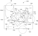
本発明のディスク選別装置の一例として、図1〜4に示すメダル選別装置100について説明する。このメダル選別装置100は、ゲーム機等に内蔵されて使用されるもので、投入されたメダルの真偽を判別して偽メダルFMをメダル返却口101へ振り分けると共に、真正メダルTMをメダル受入口102へ案内する機能を有する。メダル選別装置100は、本体103、メダル投入口104、メダル通路105、振分ゲート106、二次元撮像装置120、撮像タイミングセンサ111、メダルカウントセンサ113、制御装置140、ROM142、RAM143、ユーザインターフェース151、状態表示器152、登録スイッチ153およびセキュリティボリューム154を含んでいる。
(Constitution)
As an example of the disk sorting device of the present invention, a
本体103は、メダル投入口104およびメダル通路105が形成され、振分ゲート106、二次元撮像装置120、撮像タイミングセンサ111およびメダルカウントセンサ113が取り付けられる機能を有する。本体103は、矩形箱形であって、樹脂により製造されている。本体103において、メダル通路105の一側壁に矩形の撮像窓110が設けられている。
The
メダル投入口104は、ゲーム機等の投入口(図示せず)に投入された硬貨を受け入れる機能を有する。メダル投入口104は、本体103の上面の左端部に片寄せて形成され、スリット状の断面形状を有している。
The
メダル通路105は、メダル投入口104に投入され、落下又は転動するメダルMを案内する機能を有する。メダル通路105は、本体103内に形成され、メダル投入口104とほぼ同一のスリット状の断面形状を有している。メダル通路105は、図1に示すように、メダル投入口104から垂下する垂立メダル通路105Vおよびその下流において左斜め下方へ下向きに傾斜する傾斜メダル通路105Sを含んでいる。よって、メダル投入口104に投入されたメダルMは、垂立メダル通路105Vを垂直に落下した後、ガイドレール108によって案内される。ガイドレール108は、図1に示すように、案内線GLに沿って形成された案内面108aを有し、メダルMの転動方向に向かって前下がりに傾斜している。そのため、メダルMはガイドレール108により右側へ案内され、ガイドレール108の案内面108a上を転動して傾斜メダル通路105Sを移動する。換言すれば、傾斜メダル通路105Sにおいて、メダルMの周面は案内線GLを介してガイドレール108に接触し、ガイドレール108により支持されつつ案内線GLに沿って右側に案内される。なお、ガイドレール108として平板以外の形状のものも使用可能であり、例えば、ガイドレール108を棒状体で構成してもよい。その場合、メダルMは、傾斜メダル通路105S内において本体103に形成される案内面103aにもたれ掛かりつつ、周面をガイドレール108に支持されて案内線GL上を転動する。
The
振分ゲート106は、傾斜メダル通路105Sに進退自在に配置された振分板109を有している。振分板109が傾斜メダル通路105Sに進入した場合、転動するメダルMをガイドレール108上から逸らせて落下させ、メダル返却口101へ返却する。振分板109が傾斜メダル通路105Sから退出した場合、メダルMはガイドレール108上を転動して振分ゲート106を通過する。振分板109は、制御装置140からのゲート制御信号GCSによって傾斜メダル通路105Sへ進入する。なお、通常、振分板109は傾斜メダル通路105Sに進入した状態(すなわち、振分ゲート106が閉じた状態)が保持されている。
The sorting
二次元撮像装置120は、メダル通路105を移動するメダルMの一面の画像を二次元で撮像する機能を有する。二次元撮像装置120は、投光装置121、ハーフミラー122、集光レンズ123および撮像素子124を含んでいる。
The two-
投光装置121はハーフミラー122を介してメダル通路105を移動するメダルMの一面に光を投光する機能を有する。投光装置121は、例えば、面投光装置130である。面投光装置130を用いることにより、メダルMの回転位相が異なっても影の影響のない撮像が可能であるからである。面投光装置130は、発光ダイオード(以下、LEDという)131、導光体132、反射シート133および拡散シート134を含んでいる。
The light projecting
LED131は、メダルMへ投光するための光源である。LED131には三色LEDが使用され、LED131が白色可視光を照射する。しかし、LED131として、白色LEDを用いることもできる。LED131は、図2に示すように、導光体132の側端面に面して配置されているので、メダル通路105と平行な面内に配置することができ、設置スペースは小さい。なお、図2に示すLED131の位置は便宜的に図示したものである。
The
導光体132は、本実施例において、低コストの観点から樹脂にて製造された矩形薄板状をしており、メダル通路105に対しその面が平行に配置されている。樹脂は、透明又は拡散材の混入により乳白色を呈する。拡散材を混入した場合、拡散シート134は不要となる。導光体132は、ガラス基板によって構成することもできる。本実施例では、撮像窓110に導光体132が相対している。
In this embodiment, the
反射シート133は、導光体132からメダル通路105の反対側へ光が拡散するのを防止し、メダル通路105側に反射する機能を有する。反射シート133は、導光体132のメダル通路105の反対側に位置する面に密着されている。なお、反射シート133に代えて、導光体132に銀幕を蒸着しても良い。
The
拡散シート134は、導光体132のメダル通路105側の面から投光される光を面均一に拡散させる機能を有する。したがって、導光体132によって導かれ、または、反射シート133によって反射されたLED131からの投射光は、拡散シート134によって面全体に亘って均一な光量にされ、メダル通路105に向けて投光される。これにより、メダルMに均一な投光がなされる。拡散シート134から投射される投射光は、メダル通路105、換言すれば、メダル通路105を移動するメダルMに対し直角に投射される。これは、メダルMの表面の凹凸による光学的な影を作らないためである。導光体132、反射シート133および拡散シート134は薄いので、投光装置121を小型にすることができる。
The
ハーフミラー122は、光の一部を反射すると共に、一部を透過する機能を有する。具体的には、投光装置121からの投光は透過し、メダルMからの反射光は反射する機能を有する。換言すれば、ハーフミラー122は、投光装置121からの投光をメダル通路105におけるメダルMに対し直角に投光し、かつ、メダルMからの反射光をメダル通路105と平行な方向に反射させる。本実施例において、ハーフミラー122は薄い透明樹脂にクロムを蒸着メッキしたものである。これは、低コスト化のためである。しかし、ガラス板にクロムをメッキしてもよい。ハーフミラー122は、撮像窓110の側方において、メダル通路105の面に対し45度の角度でメダル通路105から離れるほど左下方に位置するよう傾斜配置されている。具体的には、ハーフミラー122は、傾斜メダル通路105Sの左下領域においてメダル通路105に対し45度の角度で傾斜している。ハーフミラー122の長手軸線LLは、対面するメダル通路105におけるメダルMの進行線DL(傾斜メダル通路105Sに相対しているので僅かに傾斜した水平線になる)に対して所定角度傾斜する方向に配置されている。
The
集光レンズ123は、ハーフミラー122によって反射された光を所定の小さな範囲に集光する機能を有する。集光レンズ123は、上記機能から、所定の屈折率を有する凸レンズであり、本体103内においてハーフミラー122の左側方に配置され、ハーフミラー122と同等又は小さい直径を有している。投光装置121等の形状を工夫し、集光レンズ123を小型化することが好ましい。これは、低価格化及び小型化のためである。
The condensing
撮像素子124は、集光レンズ123によって集光された像を撮像する機能を有する。撮像素子124は、集光レンズ123の左側方に配置されている。撮像素子124は、小型化のため、CCDイメージセンサやCMOSイメージセンサが採用される。
The
撮像タイミングセンサ111は、メダル通路105を転動するメダルMが撮像窓110に相対するタイミングを検知する機能を有する。撮像タイミングセンサ111は、撮像窓110下流の傾斜メダル通路105Sに配置され、メダルMの中心がハーフミラー122の長手軸線LL上方(換言すれば、後述の基準線BL上)に達したときに撮像タイミングセンサ111がメダルMを検知できるよう配置されている。そのため、撮像タイミングセンサ111は、メダルMを最適に撮像できるタイミングを示すタイミング信号TSをメダルMの検知出力として出力する。
The
撮像タイミングセンサ111としては、メダルMの位置をより正確に検知できる光電式のセンサを用いるのが好ましい。本実施例では、撮像タイミングセンサ111は、発光部112a、受光部112bおよびプリズム112cを含む光電センサ112である。発光部112aから出射した光がプリズム112cを介して受光部112bに入射するよう発光部112a、受光部112bおよびプリズム112cが配置され、メダルMが発光部112aから出射した光を遮ることによりメダルMの通過が検知されるよう構成されている。換言すれば、発光部112aから出射される光の軸(すなわち、光軸LA)によりメダルMを検知する検知軸線DALが形成され、検知軸線DALをメダルMの周面が横切ることによりメダルMが検知される。
As the
検知軸線DALは、撮像窓110に直角な方向(図1の紙面表側から裏側に向かう方向)から見て、メダルMの進行線DLにほぼ直角な方向に配置されるのが好ましい。換言すれば、検知軸線DALは傾斜メダル通路105Sにおいてガイドレール108の案内線GLにほぼ直角な方向に配置されるのが好ましい。これにより、検知軸線DALが傾斜メダル通路105Sを最短距離で横切ることとなり、撮像タイミングセンサ111を最も効率良く設置できるからである。すなわち、案内線GLに対し直角な方向から見て、撮像タイミングセンサ111の設置に必要な領域が最小となるので、メダル選別装置100を小型化できる利点がある。しかし、検知軸線DALの案内線GLに対する角度は、90度に限定されるものではなく、メダル通路105の形状や撮像タイミングセンサ111の配置に応じて適宜に設定できる。
The detection axis DAL is preferably arranged in a direction substantially perpendicular to the progress line DL of the medal M when viewed from a direction perpendicular to the imaging window 110 (a direction from the front side to the back side in FIG. 1). In other words, the detection axis DAL is preferably arranged in a direction substantially perpendicular to the guide line GL of the
なお、撮像タイミングセンサ111の受光部122bは、傾斜メダル通路105Sを挟んで発光部122aと対向する位置に配置することもできる。その場合、プリズム122cは不要となる。
Note that the light receiving unit 122b of the
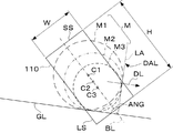
撮像窓110は、傾斜メダル通路105Sの一側壁に設けられた平面視矩形の開口からなり、傾斜メダル通路105Sを転動するメダルMの撮像領域を画定する機能を有する。図3に示すように、撮像窓110の高さH(換言すれば、長辺LSの長さ)は、最大径の選別対象メダルM1の直径よりも幅広に形成されている。縦方向においてメダルMの直径に関する情報を取得するためのである。撮像窓110の幅W(換言すれば、短辺SSの長さ)は、最小径の選別対象メダルM3の直径よりも僅かに小さく形成してある。転動するメダルMが傾斜メダル通路105Sから外れることを防止すると共に、ハーフミラー122の横方向の大きさを規制し、メダル通路105に対し45度の角度で傾斜配置されるハーフミラー122の離れ量を規制し、装置を小型化するためである。しかし、他の飛び出し防止手段を設けることにより、撮像窓110の幅WをメダルMの直径よりも大きくすることができる。なお、撮像窓110は矩形以外の形状であってもよいが、撮像素子124の撮像面を有効利用できる矩形状が好ましい。撮像素子124は、一般的に矩形状の有効撮像面を有しているからである。
The
撮像窓110に直角な方向から見て、ガイドレール108の案内線GLと撮像タイミングセンサ111の検知軸線DALとのなす角ANGの二等分線を基準線BLとした場合、撮像窓110の長辺が基準線BLと平行になるよう撮像窓110が配置される。換言すれば、撮像窓110は基準線BLに沿って延在している。なお、ハーフミラー122の長手軸線LLは、基準線BLに平行であり、撮像窓110に直角な方向に基準線BLから所定距離を隔てて配置される。換言すれば、撮像窓110に直角な方向から見て長手軸線LLと基準線BLとが重なるよう配置される。
When the bisector of the angle ANG formed by the guide line GL of the
メダルカウントセンサ113は、振分ゲート106を通過したメダルMを検知する機能を有する。メダルカウントセンサ113は、振分ゲート106の下流の傾斜メダル通路105Sの端部に配置され、1つまたは複数設けられる。本実施例では、1つのメダルカウントセンサ113が設けられている。メダルカウントセンサ113は、真正メダルTMと判断されたメダルMを検知するメダル検知信号DSを出力する。よって、メダル検知信号DSを計数することにより、受け入れた真正メダルTMの個数を判別することができる。メダルカウントセンサ113としては、光電式や磁気式のセンサが用いられる。本実施例では、メダルカウントセンサ113は、撮像タイミングセンサ111と同様に、発光部114a、受光部114bおよびプリズム114cを含む光電センサ114である。発光部114aから出射した光がプリズム114cを介して受光部114bに入射するよう発光部114a、受光部114bおよびプリズム114cが配置され、メダルMが発光部114aから出射した光を遮ることによりメダルMの通過が検知されるよう構成されている。
The
制御装置140は、撮像タイミングセンサ111から出力されるタイミング信号TSに基づき撮像素子124およびLED131の作動を制御すると共に、撮像素子124から出力される撮像画像信号ISを受けてメダルMの真偽を判別し、その判別結果に基づき振分ゲート106の開閉を制御してメダル通路105を転動するメダルMを選別する機能を有する。また、制御装置140は、メダルカウントセンサ113から出力されるメダル検知出信号DSに基づき、真正メダルTMと判別された個数を計数する機能も有する。制御装置140は、例えば、所定のプログラムに基づき動作するマイクロコンピュータ141によって構成される。制御装置140は、種々の画像処理を実行する画像処理部160を含んでいる。画像処理部160の詳細については後述する。
The
ROM142は、制御装置140を動作させるプログラムおよびデータを格納する機能を有する。ROM142は、図4に示すように、後述の基準画像を保持する基準画像保持部171を含んでいる。
The
RAM143は、制御装置140の動作中に必要なデータを一時的に格納する機能を有する。RAM143は、図4に示すように、撮像素子124により撮像されたメダルMの撮像画像を保持する撮像画像保持部172と、画像処理部160で生成された画像を保持する処理画像保持部173とを含んでいる。
The
ユーザインターフェース151は、メダル選別装置100が組み込まれるゲーム機などの本体機器(図示せず)に電気的に接続する機能を有する。ユーザインターフェース151を介して本体機器をメダル選別装置100に接続することにより、本体機器に対して所望の信号を入出力可能である。
The
状態表示器152は、メダル選別装置100の動作状態を表示する機能を有する。状態表示器152は、例えば、発光色の異なる複数のLED(図示せず)により構成され、それらLEDの発光が制御装置140により制御されることにより、メダル選別装置100の様々な状態(例えば、正常動作やエラー発生等)が報知される。なお、状態表示器152としては、液晶パネルなどのディスプレイ装置も使用可能である。
The
登録スイッチ153は、後述する基準画像の登録において使用され、登録の開始および終了を制御装置140に指示する機能を有する。
The
セキュリティボリューム154は、メダル選別装置100において偽メダルFMと判別する基準値を設定する機能を有する。制御装置140は、セキュリティボリューム154により設定された基準値に基づいてメダルMの真偽を判別する。
The
次に、図4を参照しながら、画像処理部160について説明する。画像処理部160は、中心抽出部161、エッジ強調部162、2値化部163、膨張・収縮部164、サイズ変換部165、画像回転部166、画像移動部167および判別部168を含んでいる。
Next, the
中心抽出部161は、RAM143の撮像画像保持部172に保持された撮像画像に基づき、撮像画像におけるメダルMの中心位置を抽出する機能を有する。換言すれば、撮像画像においてメダルMの中心を示す座標値を算出する。後述するように、メダルMの中心は基準線BL上に位置するため、撮像画像において基準線BLに対応する直線上におけるメダルMの周縁部の一方と他方とを検出し、両周縁部間の中点をメダルMの中心位置とする。なお、中心位置の抽出には公知の方法を用いてもよい。例えば、撮像画像において縦軸(Y軸)方向に延びる各ラインに対しメダルMの周縁部の一方と他方とを検出し、検出された両周縁部の間隔が最大となるラインにおける両周縁部間の中点をメダルMの中心位置とする。しかし、基準線BL上において中心位置を抽出する方法は、上記公知の方法に比べ遥かに単純かつ容易であり、中心位置の抽出に要する時間を短縮できる。
The
エッジ強調部162は、撮像画像保持部172に保持された撮像画像においてエッジを強調する機能を有する。エッジ強調とは、画像の輪郭部の濃度勾配を急峻にし、画像をシャープにする処理である。エッジ強調は、もとの画像からその2次微分を引くこと(ラプラシアンフィルタ)やアンシャープマスクにより行なうことができる。
The
2値化部163は、エッジ強調部162でエッジ強調された撮像画像を2値化する機能を有する。2値化とは、濃淡画像を2値画像に変換する処理である。2値化では、画素値(すなわち、輝度)が所定の閾値以上の場合にその画素値を「1」とし、それ以外の場合に画素値を「0」とする。
The
膨張・収縮部164は、2値化部163で2値化された撮像画像に対し、注目画素の周辺に1画素でも白の画素があれば白に置き換える膨張処理と、注目画素の周辺に1画素でも黒の画素があれば黒に置き換える収縮処理とを繰り返し実行する機能を有する。膨張処理および収縮処理を繰り返し実行することにより、2値化された撮像画像においてノイズが除去されると共にパターン欠陥(特に、線状パターンの欠陥)が修復される。
The expansion /
サイズ変換部165は、膨張・収縮部164で膨張・収縮処理された撮像画像の画像サイズを縮小する機能を有する。サイズ変換は、公知のアフィン変換を用い、座標原点(X=0、Y=0)を基準に所定の縮小率で実行される。
The
画像回転部166は、サイズ変換部165でサイズ変換された撮像画像を回転する機能を有する。回転は、公知のアフィン変換を用い、中心抽出部161で抽出されたメダル中心位置を基準に所定の回転角度で実行される。
The
画像移動部167は、サイズ変換部165でサイズ変換された撮像画像を平行移動する機能を有する。平行移動は、公知のアフィン変換を用い、所定の方向および移動距離で実行される。換言すれば、画素で示されたX軸方向およびY軸方向の移動距離(例えば、X軸方向に1ピクセル、Y軸方向に0ピクセル)に基づき、画像全体が平行移動される。
The
なお、画像処理部160は、中心抽出部161、エッジ強調部162、2値化部163、膨張・収縮部164、サイズ変換部165、画像回転部166、画像移動部167および判別部168のそれぞれの機能を有するものであれば、ハードウェアおよびソフトウェアのいずれで構成してもよい。一部をハードウェアとし残りをソフトウェアとすることも可能である。本実施例では、処理速度を高める上で有利なハードウェアにより画像処理部160の全体を構成している。
The
上記の構成を有するメダル選別装置100では、傾斜メダル通路105SにおいてメダルMがガイドレール108に支持されつつ案内線GLに沿って斜め下方に移動し、メダルMの進行方向側の周面が撮像タイミングセンサ111の検知軸線DAL(すなわち、光電センサ112の光軸LA)上に位置したときにメダルMが撮像窓110の所定位置(すなわち、撮像位置)に達したものとして検知される。そのため、メダルMが撮像位置に達した場合、メダルMの直径に関係なくメダルMの周面が検知軸線DAL上に位置することとなる。他方、メダルMの周面はガイドレール108により案内線GLに沿って案内されるため、メダルMが撮像位置に達した場合、メダルMの周面は案内線GL上に位置する。すなわち、図3に示すように、撮像窓110に直角な方向から見て、最大径メダルM1、中間径メダルM2および最小径メダルM3のそれぞれの外周が検知軸線DALおよび案内線GLに接した状態となる。これは、撮像窓110に直角な方向から見て、メダルM1、M2、M3の中心C1、C2、C3が案内線GLと検知軸線DALとのなす角の二等分線上に位置することを意味する。したがって、この二等分線を基準線BLとし、その基準線BLに沿って撮像窓110を延在させることにより、異なる直径を有するメダルMであってもその一面に形成された模様の全体を容易かつ確実に撮像することができる。よって、容易かつ確実な判別および選別が可能となる。換言すれば、模様の全体を撮像できるメダルMの直径範囲が広くなるので、判別および選別可能な直径範囲が広くなる。しかも、撮像窓110に直角な方向から見て基準線BLに直角な方向については、異なる直径のメダルMであっても中心位置の移動を考慮せずに撮像窓110の幅Wを設定できるため、撮像窓110の幅Wを比較的小さくできる。換言すれば、上記した従来装置のようにメダルMの中心位置のシフトやズレに伴って撮像領域を大きくする必要がない。したがって、メダル選別装置100を小型化できる。また、複数の撮像タイミングセンサ111を必要としないので、低コストであり、かつ、煩雑な調整も不要であり、容易に実現できる。また、画像判別の基準となるメダルMの中心位置を求める際に、基準線BL上に中心位置が存在するため、中心位置の抽出は単純かつ容易であり、判別に必要な処理時間が短縮される。換言すれば、選別に要する時間が短縮され、より高速な選別が可能となる。
In the
撮像窓110の形状は長辺LSおよび短辺SSを有する矩形であり、矩形の長辺LSが基準線BLにほぼ平行になるよう撮像窓110が配置される。一般に撮像素子124は矩形の有効撮像面を有するため、撮像窓110を矩形状とすることにより、撮像素子124における撮像面の利用効率を向上させることができる。
The shape of the
撮像窓110に対し直角な方向から見て、基準線BLに対し対称となるよう撮像窓110が配置される。換言すれば、撮像窓110の短辺方向の中心軸線が基準線BLと重なるよう撮像窓110が配置される。これにより、撮像タイミングセンサ111によるメダルMの検知から撮像素子124によるメダルMの撮像までの時間差が無視できる程度であれば、撮像窓110において矩形の短辺方向の中心にメダルMの中心が配置されるので、模様の全体をより効率よく撮像できる。
The
撮像タイミングセンサ111として光電センサ112を用い、光電センサ112の光軸LAが検知軸線DALを形成する。したがって、指向性および直線性の高い光によりメダルMを検知するため、検知精度を高めることができる。
A
(動作)
次に、図6〜図12を参照しながら、メダル選別装置100の動作について説明する。以下、制御装置140の処理を中心に説明する。
(Operation)
Next, the operation of the
まず、図6に示すように、ステップS1において、初期化がなされる。初期化では、撮像素子124のフレームレート、撮像タイミングセンサ111およびメダルカウントセンサ113の感度などが設定される。
First, as shown in FIG. 6, initialization is performed in step S1. In initialization, the frame rate of the
次のステップS2において、撮像タイミングセンサ111がオンしたか否かが判定される。換言すれば、メダル通路105を転動するメダルMが撮像位置に到達したか否かが判定される。撮像タイミングセンサ111がオフの場合、ステップS3に進み、撮像タイミングセンサ111がオンの場合、ステップS5に進む。
In the next step S2, it is determined whether or not the
ステップS3では、基準画像を登録するか否かが判定される。すなわち、登録スイッチ153がオンされたか否かが判定される。登録スイッチ153がオンの場合、ステップS4に進み、登録スイッチ153がオフの場合、ステップS2に戻る。
In step S3, it is determined whether or not to register a reference image. That is, it is determined whether or not the
メダル投入口104にメダルMが投入された場合、投入されたメダルMは垂立メダル通路105Vを落下した後、傾斜メダル通路105Sを転動し、撮像タイミングセンサ111がオンする。すなわち、メダル投入口104へのメダルMの投入に対応して、撮像タイミングセンサ111がオンする。メダル投入口104にメダルMが投入されず、かつ、登録スイッチ153がオンされない場合、ステップS2およびステップS3が繰り返し実行される。換言すれば、メダルMの投入および登録スイッチ153のオンのいずれかがなされるまでは、待機状態となる。
When the medal M is inserted into the
ステップS4では、図7に示す各ステップにより基準画像の登録が実行される。基準画像の登録は、真偽判別の基準となるメダル(以下、基準メダルSMという)の表面および裏面の画像を撮像素子124により取得して行われる。基準メダルSMとしては、判別精度を高める上で未使用のメダルMを使用することが好ましいが、使用済みのメダルMでもよい。図7の基準画像登録では、最初のステップS21において、登録設定がなされる。登録設定では、例えば、登録する画像がメダルMの表面および裏面のいずれであるかの選択がなされる。
In step S4, registration of the reference image is executed by each step shown in FIG. The registration of the reference image is performed by acquiring images of the front and back surfaces of a medal (hereinafter referred to as a reference medal SM) serving as a reference for authenticity determination by the
次のステップS22では、登録が終了したか否かが判定される。登録終了は、登録スイッチ153がオフされたか否かで判定される。登録スイッチ153がオフされた場合、図6のステップS4に戻り、登録スイッチ153がオフされていない場合、ステップS23に進む。
In the next step S22, it is determined whether or not the registration is completed. The end of registration is determined by whether or not the
次のステップS23では、上述のステップS2と同様に、撮像タイミングセンサ111がオンしたか否かが判定される。メダル投入口104に基準メダルSMが投入され、撮像タイミングセンサ111がオンとなった場合、ステップS24に進む。撮像タイミングセンサ111がオフの場合、ステップS23が繰り返し実行される。換言すれば、メダル投入口104に基準メダルSMが投入される迄は、待機状態となる。
In the next step S23, it is determined whether or not the
次のステップS24では、制御装置140がLED131に点灯制御信号LCSを出力し、LED131が点灯制御信号LCSに基づいて短時間点灯(すなわち、フラッシュ)される。これにより、投光装置121から撮像窓110に向かう拡散光が発せられ、撮像窓110と相対するメダルMが投光される。
In the next step S24, the
次のステップS25では、制御装置140が撮像素子124に撮像制御信号ICSを出力し、撮像素子124が撮像制御信号ICSに基づいて基準メダルSMを撮像する。撮像素子124は、取得された撮像画像を含む撮像画像信号ISを制御装置140に出力する。制御装置140は、供給された撮像画像信号ISに含まれる撮像画像を図5に示すバスラインBSを介してRAM143に転送する。RAM143は、送られた撮像画像を撮像画像保持部172に格納し保持する。
In the next step S25, the
次のステップS26では、回転角度θに「0」が設定される。換言すれば、回転角度θが初期化(すなわち、リセット)される。 In the next step S26, “0” is set to the rotation angle θ. In other words, the rotation angle θ is initialized (that is, reset).
次のステップS27では、制御装置140の画像処理部160が撮像画像保持部172に保持された撮像画像に対し前処理を実行する。前処理は、図8に示すように、中心抽出、エッジ強調、2値化、膨張・収縮、サイズ変換の順で実行される。まず、ステップS41において、中心抽出部161が撮像画像保持部172に保持された撮像画像における基準メダルSMの中心位置を抽出する。抽出された中心位置の座標値はRAM143に格納される。
In the next step S <b> 27, the
次のステップS42では、エッジ強調部162が撮像画像保持部172に保持された撮像画像についてエッジ強調の処理を実行する。エッジ強調された撮像画像は、RAM143の処理画像保持部173に保持される。
In the next step S <b> 42, the
続くステップS43では、2値化部163が処理画像保持部173に保持されたエッジ強調後の撮像画像を2値化する。2値化された撮像画像は、処理画像保持部173に保持される。
In subsequent step S43, the
その後、ステップS44において、膨張・収縮部164が処理画像保持部173に保持された2値化後の撮像画像に対し膨張・収縮処理を実行する。膨張・収縮処理により、2値化された撮像画像のノイズ除去やパターン欠陥の修復等がなされる。膨張・収縮された撮像画像は、処理画像保持部173に保持される。
Thereafter, in step S <b> 44, the expansion /
さらに、ステップS45では、サイズ変換部165が処理画像保持部173に保持された膨張・収縮後の撮像画像をサイズ変換する処理を実行する。サイズ変換処理により、膨張・収縮処理された撮像画像が縮小されて画素数が減少する。サイズ変換された撮像画像は、処理画像保持部173に保持される。こうして前処理が完了し、当該前処理が施された撮像画像は処理画像保持部173に保持される。その後、図7のステップS27に戻る。
Furthermore, in step S45, the
図7のステップS28では、データがROM142に格納される。すなわち、前処理を施された撮像画像は、バスラインBSを介してRAM143からROM142に転送され、基準画像保持部171に回転角度θ=0の基準画像として格納され保持される。換言すれば、基準画像が回転角度θと関連付けられて基準画像保持部171に保持される。このとき、RAM143の撮像画像保持部172に保持されていた撮像画像は、継続して撮像画像保持部172に保持される。
In step S28 of FIG. 7, the data is stored in the
次のステップS29では、新たな回転角度θとして現在の回転角度θに回転角度増分θdを加算した「θ+θd」が設定される。換言すれば、回転角度θに回転角度増分θdを加算することにより、回転角度θが更新される。本実施例では、画像を1回転したときにθ=0の基準画像を含めて全64枚の基準画像が得られるように、θdが設定される。この場合のθdは「5.625°」である。 In the next step S29, “θ + θd”, which is obtained by adding the rotation angle increment θd to the current rotation angle θ, is set as the new rotation angle θ. In other words, the rotation angle θ is updated by adding the rotation angle increment θd to the rotation angle θ. In this embodiment, θd is set so that a total of 64 reference images including the reference image of θ = 0 can be obtained when the image is rotated once. In this case, θd is “5.625 °”.
次のステップS30では、回転角度θが360°以上であるか否かが判定される。回転角度θが360°未満(すなわち、「θ<360°」)の場合、ステップS31においてRAM143の撮像画像保持部172に保持された撮像画像を設定された回転角度θで回転した後、ステップS27に戻り、ステップS27〜S31が繰り返し実行される。これにより、複数の回転角度θにそれぞれ対応する複数の基準画像がROM142の基準画像保持部171に格納され保持される。換言すれば、基準メダルSMの撮像画像およびその撮像画像をそれぞれ異なる複数の回転角度θで回転させた画像からなる複数の基準画像が基準画像保持部171に保持される。
In the next step S30, it is determined whether or not the rotation angle θ is 360 ° or more. Rotation angle theta is less than 360 ° (i.e., "theta <360 °"), the after rotating at an angle theta which is set the captured image stored in the captured
ステップS30において回転角度θが360°以上(すなわち、「θ≧360°」)の場合、ステップS21に戻り、上記のステップS21〜S31が繰り返される。これにより、基準メダルSMの表面および裏面のそれぞれについて、複数の基準画像が登録可能である。 Rotation angle theta is more than 360 ° in step S30 (i.e., "theta ≧ 360 °"), the process returns to step S21, the above steps S 21~S31 is repeated. Accordingly, a plurality of reference images can be registered for each of the front and back surfaces of the reference medal SM.
なお、基準画像の登録において、基準メダルSMの表面および裏面のいずれかを特定する面番号kが設定される。すなわち、基準メダルSMの表面に対応する基準画像には、面番号kとして「0」が設定される。同様に、基準メダルSMの裏面に対応する基準画像には、面番号kとして「1」が設定される。そして、基準画像保持部171には、面番号kが複数の基準画像と共に格納され保持される。これにより、面番号kに基づき、基準メダルSMにおける表面の基準画像と裏面の基準画像とを区別することができる。
In registering the reference image, a surface number k that specifies either the front surface or the back surface of the reference medal SM is set. That is, “0” is set as the face number k in the reference image corresponding to the surface of the reference medal SM. Similarly, “1” is set as the face number k in the reference image corresponding to the back face of the reference medal SM. The reference
また、基準画像を登録する場合、取得画像を回転(図7のステップS31)した後の前処理(図7のステップS31)において中心抽出、エッジ強調、2値化、膨張・収縮およびサイズ変換(図8のステップS41〜S45)の全てを実行しているが、当該前処理において中心抽出、エッジ強調、2値化、膨張・収縮の処理を省略することもできる。すなわち、「θ=0」の場合(換言すれば、回転していない画像の場合)には、ステップS27において中心抽出、エッジ強調、2値化および膨張・収縮を実行した後の処理画像(換言すれば、サイズ変換前の処理画像)をRAM143に保持してからサイズ変換を実行し、「0<θ<360°」の場合には、ステップS31においてRAM143に保持されたサイズ変換前の処理画像を回転させ、その後に実行されるステップS27においてサイズ変換のみを実行すればよい。こうすることにより、基準画像の登録に要する時間を短縮できる。
In addition, when registering a reference image, center extraction, edge enhancement, binarization, expansion / contraction, and size conversion (in step S31 in FIG. 7) after the acquired image is rotated (step S31 in FIG. 7) ( Although all steps S41 to S45) in FIG. 8 are executed, the center extraction, edge enhancement, binarization, and expansion / contraction processes can be omitted in the preprocessing. That is, in the case of “θ = 0” (in other words, in the case of an image that is not rotated), the processed image (in other words, the image after the center extraction, edge enhancement, binarization, and expansion / contraction are performed in step S27). In this case, the size conversion is executed after holding the processed image before size conversion) in the
ここからは、図6の説明に戻る。選別対象(換言すれば、判別対象)のメダルMがメダル投入口104に投入され、ステップS4において撮像タイミングセンサ111がオンした場合、ステップS5では、図7のステップS24と同様に、制御装置140がLED131に点灯制御信号LCSを出力し、LED131が点灯制御信号LCSに基づいて短時間点灯(すなわち、フラッシュ)される。これにより、投光装置121から撮像窓110に向かう拡散光が発せられ、撮像窓110と相対する選別対象のメダルMが投光される。
From here, it returns to description of FIG. When the medal M to be selected (in other words, to be discriminated) is inserted into the
次のステップS6では、図7のステップS25と同様に、制御装置140が撮像素子124に撮像制御信号ICSを出力し、撮像素子124が撮像制御信号ICSに基づいてメダルMを撮像する。撮像素子124は、取得された撮像画像を含む撮像画像信号ISを制御装置140に出力する。制御装置140は、供給された撮像画像信号ISに含まれる撮像画像をRAM143の撮像画像保持部172に格納し保持する。
In the next step S6, as in step S25 of FIG. 7, the
なお、ステップS6で取得される撮像画像は、選別対象のメダルMにおける表面および裏面のいずれかの画像である。そのため、メダルMの表面および裏面に形成された模様が異なる場合、基準メダルSMの表面および裏面のそれぞれの基準画像と対比する必要がある。本実施例では、メダルMの表面および裏面に形成された模様が異なるものとして説明する。 Note that the captured image acquired in step S6 is one of the front and back surfaces of the medal M to be selected. Therefore, when the patterns formed on the front and back surfaces of the medal M are different, it is necessary to compare with the respective reference images on the front and back surfaces of the reference medal SM. In the present embodiment, description will be made assuming that the patterns formed on the front surface and the back surface of the medal M are different.
次のステップS7では、図7のステップS27と同様に、図8のステップS41〜S45において、中心抽出、エッジ強調、2値化、膨張・収縮、サイズ変換の順で前処理が実行される。このとき、前処理が施された撮像画像は、RAM143の処理画像保持部173に保持される。RAM143の撮像画像保持部172に保持されていた撮像画像は、継続して撮像画像保持部172に保持される。
In the next step S7, as in step S27 in FIG. 7, preprocessing is executed in the order of center extraction, edge enhancement, binarization, expansion / contraction, and size conversion in steps S41 to S45 in FIG. At this time, the pre-processed captured image is held in the processed
次のステップS8では、制御装置140が上述の面番号kに「0」を設定する。これにより、後述の画像対比判定(ステップS10)において、初めに「k=0」に対応する基準画像との対比がなされる。
In the next step S8, the
次のステップS9では、制御装置140が画像移動カウント数nに「0」を設定する。換言すれば、画像移動カウント数nが初期化(すなわち、リセット)される。
In the next step S9, the
次のステップS10では、図9および図10に示す画像対比判定が実行される。まず、図9のステップS51において、画像移動カウント数nが「0」か否かが判定される。換言すれば、ステップS51は、後述する平行移動が実行されているか否かを判定する。平行移動が実行されていない「n=0」の場合、ステップS52に進み、平行移動が実行されている「n≠0」の場合、図10のステップS71に進む。 In the next step S10, the image comparison determination shown in FIGS. 9 and 10 is executed. First, in step S51 of FIG. 9, it is determined whether or not the image movement count number n is “0”. In other words, in step S51, it is determined whether or not a later-described parallel movement is being performed. If “n = 0” in which the parallel movement is not executed, the process proceeds to step S52. If “n ≠ 0” in which the parallel movement is executed, the process proceeds to step S71 in FIG.
「n=0」の場合に実行されるステップS52では、回転角度θに「0」が設定され、次のステップS53において、ROM142の基準画像保持部171に保持された複数の基準画像のうち、面番号kおよび回転角度θの基準画像が選択される。最初に「k=0、θ=0」の基準画像が選択される。
In step S52 executed when “n = 0”, “0” is set to the rotation angle θ, and among the plurality of reference images held in the reference
次のステップS54では、選択された基準画像と処理画像保持部173に保持された前処理後の撮像画像とを対比する画像比較が実行される。画像比較では、選択された基準画像および前処理後の撮像画像を画素単位で比較し、画素値の相違する画素数をカウントすることにより相違度DFが算出される。
In the next step S <b> 54, image comparison for comparing the selected reference image with the pre-processed captured image held in the processed
なお、相違度DFに換えて類似度に基づき判定することも可能である。その場合、画素値の一致する画素数をカウントすることにより類似度を算出し、算出された類似度が所定の閾値以上である場合に一致すると判定すればよい。 It is also possible to make a determination based on the similarity instead of the difference DF. In that case, the similarity may be calculated by counting the number of pixels with matching pixel values, and if the calculated similarity is equal to or greater than a predetermined threshold, it may be determined that they match.
次のステップS55では、算出された相違度DFが所定の閾値以下であるか否かが判定される。相違度DFが閾値以下の場合、ステップS56において、一致の判定がなされた後、図6のステップS10に戻る。それ以外の場合、ステップS57に進む。 In the next step S55, it is determined whether or not the calculated difference DF is equal to or less than a predetermined threshold value. If the dissimilarity DF is less than or equal to the threshold value, a match is determined in step S56, and the process returns to step S10 in FIG. Otherwise, the process proceeds to step S57.
ステップS57では、θが「0」であるか否かが判定される。「θ=0」の場合、ステップS59に進み、「θ≠0」の場合、ステップS58に進む。 In step S57, it is determined whether or not θ is “0”. If “θ = 0”, the process proceeds to step S59, and if “θ ≠ 0”, the process proceeds to step S58.
ステップS59および次のステップS60では、相違度DFの最小値を示す最小相違度DFmと、相違度DFが最小となる最小相違度回転角度θmとが設定される。ステップS59において最小相違度DFmとして現在の相違度DFが設定され、ステップS60において最小相違度回転角度θmとして現在の回転角度θが設定される。設定された最小相違度DFmおよび最小相違度回転角度θmは、RAM143に格納される。
In step S59 and the next step S60, a minimum dissimilarity DFm indicating the minimum value of the dissimilarity DF and a minimum dissimilarity rotation angle θm that minimizes the dissimilarity DF are set. In step S59, the current difference degree DF is set as the minimum difference degree DFm, and in step S60, the current rotation angle θ is set as the minimum difference degree rotation angle θm. The set minimum difference DFm and minimum difference rotation angle θm are stored in the
「θ≠0」の場合のステップS58では、相違度DFが最小相違度DFm未満であるか否かが判定される。「DF<DFm」の場合、すなわち、ステップS54で算出された相違度DFが既に設定されている最小相違度DFmより小さい場合、ステップS59に進み、ステップS59およびS60により、最小相違度DFmおよび最小相違度回転角度θmが更新される。「DF≧DFm」の場合、ステップS61に進み、現在の最小相違度DFmおよび最小相違度回転角度θmがそのまま維持される。 In step S58 in the case of “θ ≠ 0”, it is determined whether or not the difference DF is less than the minimum difference DFm. If "DF <DFm", i.e., if the minimum dissimilarity DFm smaller degree of difference DF calculated in step S 54 has already been set, the process proceeds to step S59, the step S59 and S60, the minimum dissimilarity DFm and The minimum difference degree rotation angle θm is updated. If “DF ≧ DFm”, the process proceeds to step S61, and the current minimum difference DFm and the minimum difference rotation angle θm are maintained as they are.
次のステップS61では、現在の回転角度θに回転角度増分θdを加算して得られた値が新たな回転角度θとして設定される。換言すれば、回転角度θが更新される。 In the next step S61, a value obtained by adding the rotation angle increment θd to the current rotation angle θ is set as a new rotation angle θ. In other words, the rotation angle θ is updated.
次のステップS62では、ステップS61で更新された回転角度θが「360°」以上であるか否かが判定される。「θ≧360°」の場合、ステップS63において不一致の判定がなされ、図6のステップS10に戻る。「θ<360°」の場合、ステップS53に戻り、ステップS53〜S62が繰り返し実行される。これにより、回転角度θを増加させながら、各回転角度θに対応する複数の基準画像のそれぞれについて相違度DFが算出され、算出された相違度DFと閾値との比較結果から一致および不一致のいずれかの判定がなされる。なお、ステップS63で不一致と判定された場合、最小相違度DFmおよび最小相違度回転角度θmが確定する。換言すれば、不一致の判定がなされた場合、回転角度θが「0≦θ<360°」の範囲で準備された複数の基準画像において最小相違度DFmが得られる最小相違度回転角度θmがRAM143に保持される。
In the next step S62, it is determined whether or not the rotation angle θ updated in step S61 is “360 °” or more. In the case of “θ ≧ 360 °”, inconsistency is determined in step S63, and the process returns to step S10 in FIG. If “θ <360 °”, the process returns to step S53, and steps S53 to S62 are repeatedly executed. As a result, the difference DF is calculated for each of a plurality of reference images corresponding to each rotation angle θ while increasing the rotation angle θ, and either a match or a mismatch is determined from the comparison result between the calculated difference DF and the threshold value. Is determined. If it is determined that there is a mismatch in step S63, the minimum difference degree DFm and the minimum difference degree rotation angle θm are determined. In other words, when the discrepancy is determined, the minimum dissimilarity rotation angle θm at which the minimum dissimilarity DFm is obtained in the plurality of reference images prepared in the range where the rotation angle θ is “0 ≦ θ <360 °” is the
ここからは、再び図6の説明に戻る。ステップS11では、ステップS9の画像対比判定において一致と判定されたか否かが判定される。換言すれば、真正メダルと判別されたか否かが判定される。一致と判定された場合(すなわち、真正メダルと判別された場合)、ステップS17に進み、不一致と判定された場合、ステップS12に進む。 From here, it returns to description of FIG. 6 again. In step S11, it is determined whether or not it is determined to match in the image comparison determination in step S9. In other words, it is determined whether or not a genuine medal is determined. If it is determined that they match (that is, if they are determined to be genuine medals), the process proceeds to step S17. If it is determined that they do not match, the process proceeds to step S12.
ステップS17では、制御装置140がゲート制御信号GCSを振分ゲート106に出力し、振分板109がメダル通路105から退出して振分ゲート106が開かれる。これにより、傾斜メダル通路105Sを転動する真正メダルTMは振分ゲート106を通過し、メダル受入口102を介して本体機器(図示せず)に導入される。換言すれば、メダル投入口104に投入されたメダルMが真正メダルTMと判別され、振分ゲート106により真正メダルTMとして選別される。
In step S17, the
次のステップS18では、メダルカウントセンサ113がオンしたか否かが判定される。メダルカウントセンサ113がオフの場合、ステップS18が繰り返し実行される。換言すれば、メダルカウントセンサ113が待機状態となる。ステップS17において真正メダルTMとして選別された場合、振分ゲート106を通過した真正メダルTMによりメダルカウントセンサ113がオンされ、ステップS19に進む。
In the next step S18, it is determined whether or not the
ステップS19では、振分板109がメダル通路105内に進入して振分ゲート106が閉ざされた後、ステップS2に戻る。これにより、上記ステップS11において真正メダルと判定されるまでは、振分ゲート106の閉じた状態が維持され、偽メダルFMがメダル返却口101に振り分けられる。
In step S19, after the
上記ステップS11において不一致と判定された場合に実行されるステップS12では、画像移動カウント数nが「8」以上か否かが判定される。画像移動カウント数nが「8」以上でない場合(すなわち、「n<8」の場合)、ステップS13に進み、図11に示す平行移動処理が実行される。 In step S12, which is executed when it is determined that there is a mismatch in step S11, it is determined whether or not the image movement count number n is “8” or more. When the image movement count number n is not “8” or more (that is, when “n <8”), the process proceeds to step S13, and the parallel movement process shown in FIG. 11 is executed.
図11の平行移動処理では、RAM143の処理画像保持部173に保持された前処理後の撮像画像が、画像移動カウント数nに対応した所定の方向に平行移動される。平行移動された前処理後の撮像画像(以下、移動撮像画像という)は、RAM143の処理画像保持部173に保持される。すなわち、ステップS91では、画像移動カウント数が「0」か否かが判定され、「n=0」の場合、ステップS98において前処理後の撮像画像が右上方に1ピクセル移動(図12(A)の位置P1に移動、すなわち、X軸方向およびY軸方向に各「+1」ピクセル移動)された後、図6のステップS12に戻る。「n≠0」の場合、ステップS92に進み、画像移動カウント数nが「1」か否かが判定される。「n=1」の場合、ステップS99において前処理後の撮像画像が上方に1ピクセル移動(図12(B)の位置P2に移動、すなわち、Y軸方向に「+1」ピクセル移動)された後、図6のステップS12に戻る。「n≠1」の場合、ステップS93に進み、画像移動カウント数nが「2」か否かが判定される。「n=2」の場合、ステップS100において前処理後の撮像画像が左上方に1ピクセル移動(図12(C)の位置P3に移動、すなわち、X軸方向に「−1」およびY軸方向に「+1」ピクセル移動)された後、図6のステップS12に戻る。「n≠2」の場合、ステップS94に進み、画像移動カウント数nが「3」か否かが判定される。「n=3」の場合、ステップS101において前処理後の撮像画像が左方に1ピクセル移動(図12(D)の位置P4に移動、すなわち、X軸方向に「−1」ピクセル移動)された後、図6のステップS12に戻る。「n≠3」の場合、ステップS95に進み、画像移動カウント数nが「4」か否かが判定される。「n=4」の場合、ステップS102において前処理後の撮像画像が右方に1ピクセル移動(図12(E)の位置P5に移動、すなわち、X軸方向に「+1」ピクセル移動)された後、図6のステップS12に戻る。「n≠4」の場合、ステップS96に進み、画像移動カウント数nが「5」か否かが判定される。「n=5」の場合、ステップS103において前処理後の撮像画像が右下方に1ピクセル移動(図12(F)の位置P6に移動、すなわち、X軸方向に「+1」およびY軸方向に「−1」ピクセル移動)された後、図6のステップS12に戻る。「n≠5」の場合、ステップS97に進み、画像移動カウント数nが「6」か否かが判定される。「n=6」の場合、ステップS104において前処理後の撮像画像が下方に1ピクセル移動(図12(G)の位置P7に移動、すなわち、Y軸方向に「−1」ピクセル移動)された後、図6のステップS12に戻る。「n≠6」の場合、ステップS105に進み、前処理後の撮像画像が左下方に1ピクセル移動(図12(H)の位置P8に移動、すなわち、X軸方向およびY軸方向に各「−1」ピクセル移動)された後、図6のステップS13に戻る。なお、図12では、平行移動の方向を明瞭に示すため、便宜的に移動距離を大きく示している。
In the parallel movement process of FIG. 11, the pre-processed captured image held in the processed
ステップS13において撮像画像が平行移動された後、次のステップS14では、現在の画像移動カウント数nに「1」が加算され、新たな画像移動カウント数nが設定される。こうして画像移動カウント数nが更新された後、ステップS10に戻り、ステップS11において一致と判定されるか、あるいはステップS12において「n≧8」と判定されるまで、ステップS10〜S14が繰り返し実行される。すなわち、ステップS13において平行移動された前処理後の撮像画像は、RAM143の処理画像保持部173に格納されて保持され、ステップS10で画像対比判定が行われる。換言すれば、移動撮像画像と複数の基準画像との対比によるメダルMの真偽の判別が、平行移動の方向を変えながら繰り返し実行される。
After the captured image is translated in step S13, in the next step S14, “1” is added to the current image movement count number n, and a new image movement count number n is set. After the image movement count number n has been updated in this way, the process returns to step S10, and steps S10 to S14 are repeatedly executed until it is determined that they match in step S11 or “n ≧ 8” is determined in step S12. The That is, the pre-processed captured image translated in step S13 is stored and held in the processed
なお、ここでは、平行移動の移動量を8方向に各1ピクセルとしているが、メダルの中心位置に対して模様のズレが大きい場合、必要に応じて2ピクセル以上とすることもできる。その場合、図11の平行移動処理において、画像移動カウント数nやピクセル数を適宜設定することにより、ピクセル数を徐々に増やすことも可能である。 Here, the amount of parallel movement is set to 1 pixel in each of the eight directions, but if the pattern shift is large with respect to the center position of the medal, it can be set to 2 pixels or more as necessary. In that case, in the parallel movement process of FIG. 11, the number of pixels can be gradually increased by appropriately setting the image movement count number n and the number of pixels.
図6のステップS10において、移動撮像画像と複数の基準画像とが対比される場合、図10に示す各ステップが実行される。すなわち、図6のステップS14において画像移動カウント数nに「1」が加算されているため、図9のステップS51の判定により図10のステップS71に進む。このステップS71では、回転角度カウント数mとして「0」が設定される。回転角度カウント数mは、RAM143に保持される。
In step S10 of FIG. 6, when the moving captured image and the plurality of reference images are compared, each step shown in FIG. 10 is executed. That is, since “1” is added to the image movement count number n in step S14 in FIG. 6, the process proceeds to step S71 in FIG. 10 by the determination in step S51 in FIG. In this step S71, “0” is set as the rotation angle count number m. The rotation angle count number m is held in the
次のステップS72では、回転角度カウント数mが「0」と一致するか否かが判定される。「m=0」の場合、ステップS73において、回転角度θとして最小相違度回転角度θmが設定された後、ステップS77に進む。「m≠0」の場合、ステップS74に進む。 In the next step S72, it is determined whether or not the rotation angle count number m matches “0”. In the case of “m = 0”, the minimum dissimilarity rotation angle θm is set as the rotation angle θ in step S73, and then the process proceeds to step S77. If “m ≠ 0”, the process proceeds to step S74.
ステップS74では、回転角度カウント数mが「1」と一致するか否かが判定される。「m=1」の場合、ステップS75において、回転角度θとして最小相違度回転角度θmから回転角度増分θdを減算した「θm−θd」が設定された後、ステップS77に進む。「m≠1」の場合、ステップS76において、回転角度θとして最小相違度回転角度θmに回転角度増分θdを加算した「θm+θd」が設定された後、ステップS77に進む。 In step S74, it is determined whether or not the rotation angle count number m is equal to “1”. In the case of “m = 1”, in step S75, “θm−θd” obtained by subtracting the rotation angle increment θd from the minimum difference rotation angle θm is set as the rotation angle θ, and then the process proceeds to step S77. If “m ≠ 1”, in step S76, “θm + θd” obtained by adding the rotation angle increment θd to the minimum difference rotation angle θm is set as the rotation angle θ, and then the process proceeds to step S77.
ステップS77では、ROM142の基準画像保持部171に保持された複数の基準画像のうち、ステップS73、S75およびS76のいずれかで設定された回転角度θに対応する基準画像が選択される。このとき、面番号kに対応する複数の基準画像の中から選択される。
In step S77, a reference image corresponding to the rotation angle θ set in any of steps S73, S75, and S76 is selected from the plurality of reference images held in the reference
次のステップS78では、図9のステップS54と同様に、選択された基準画像とRAM143の処理画像保持部173に保持された移動撮像画像とを対比する画像比較が実行される。画像比較では、選択された基準画像および移動撮像画像を画素単位で比較し、画素値の相違する画素数をカウントすることにより相違度DFが算出される。
In the next step S78, as in step S54 of FIG. 9, an image comparison that compares the selected reference image with the moving captured image held in the processed
次のステップS79では、図9のステップS55と同様に、算出された相違度DFが所定の閾値以下であるか否かが判定される。相違度DFが閾値以下の場合、ステップS80において、一致の判定がなされた後、図6のステップS10に戻る。それ以外の場合、ステップS81に進む。 In the next step S79, as in step S55 of FIG. 9, it is determined whether or not the calculated difference DF is equal to or less than a predetermined threshold value. When the dissimilarity DF is less than or equal to the threshold value, a match is determined in step S80, and the process returns to step S10 in FIG. Otherwise, the process proceeds to step S81.
ステップS81では、新たな回転角度カウント数mとして現在の回転角度カウント数mに「1」を加算した「m+1」を設定する。 In step S81, “m + 1” obtained by adding “1” to the current rotation angle count number m is set as a new rotation angle count number m.
次のステップS82では、回転角度カウント数mが「3」未満であるか否かを判定する。「m<3」の場合、ステップS72に戻り、ステップS72〜S82が繰り返し実行される。「m≧3」の場合、ステップS83において、不一致の判定がなされた後、図6のステップS10に戻る。 In the next step S82, it is determined whether or not the rotation angle count number m is less than “3”. If “m <3”, the process returns to step S72, and steps S72 to S82 are repeatedly executed. In the case of “m ≧ 3”, in step S83, a mismatch is determined, and then the process returns to step S10 in FIG.
このように、移動撮像画像と複数の基準画像とが対比される場合、平行移動していない撮像画像において最小相違度DFmが得られる最小相違度回転角度θmを第1回転角度として特定し、最小相違度回転角度θmに回転角度増分θdを減算した角度「θm−θd」を第2回転角度として特定し、最小相違度回転角度θmに回転角度増分θdを加算した角度「θm+θd」を第3回転角度として特定し、これら特定された第1〜第3回転角度に対応する基準画像と移動撮像画像とを対比することにより、一致および不一致のいずれかの判定がなされる。換言すれば、基準画像保持部171に保持された64枚の基準画像の中から3枚の基準画像を特定し、特定された3枚の基準画像についてのみ対比される。そのため、全64枚の基準画像について対比する場合に比べ、判定に要する時間が短縮できる。
Thus, when the moving captured image and the plurality of reference images are compared, the minimum difference rotation angle θm that provides the minimum difference DFm in the captured image that is not translated is specified as the first rotation angle, and the minimum The angle “θm−θd” obtained by subtracting the rotation angle increment θd from the difference rotation angle θm is specified as the second rotation angle, and the angle “θm + θd” obtained by adding the rotation angle increment θd to the minimum difference rotation angle θm is the third rotation. By specifying as an angle and comparing the reference image corresponding to the specified first to third rotation angles with the moving captured image, either a match or a mismatch is determined. In other words, three reference images are specified from the 64 reference images held in the reference
なお、図7の基準画像登録において回転角度増分θdを「5.625°」に設定し一面につき全64枚の基準画像を登録しているが、回転角度増分θdは適宜に設定できる。回転角増分θdをより小さくして一面当たりの基準画像数を適宜に増加させた場合には、平行移動後の撮像画像に対する画像対比判定において、第1回転角度(すなわち、最小相違度回転角度θm)に対応する基準画像についてのみ画像比較を行うようにすることもできる。 In the reference image registration of FIG. 7, the rotation angle increment θd is set to “5.625 °” and a total of 64 reference images are registered per surface, but the rotation angle increment θd can be set as appropriate. When the rotation angle increment θd is further decreased and the number of reference images per surface is appropriately increased, the first rotation angle (that is, the minimum dissimilarity rotation angle θm) in the image contrast determination with respect to the captured image after translation is performed. It is also possible to perform image comparison only for the reference image corresponding to ().
再び図6の説明に戻る。ステップS12において画像移動カウント数nが「8」以上の場合(すなわち、「n≧8」の場合)、ステップS15に進み、現在の面番号kに「1」が加算され、新たな面番号kが設定される。 Returning to the description of FIG. When the image movement count number n is “8” or more in step S12 (that is, when “n ≧ 8”), the process proceeds to step S15, where “1” is added to the current surface number k, and a new surface number k. Is set.
次のステップS16では、面番号kが「2」以上であるか否かが判定される。面番号kが「2」未満(すなわち、「k<2」)の場合、ステップS9に戻る。換言すれば、「k=1」に設定された状態で、ステップS9〜S14の処理が再度実行される。すなわち、基準メダルSMの裏面の基準画像との対比が行われる。 In the next step S16, it is determined whether or not the surface number k is “2” or more. If the face number k is less than “2” (ie, “k <2”), the process returns to step S9. In other words, the processes of steps S9 to S14 are executed again in a state where “k = 1” is set. That is, a comparison with the reference image on the back surface of the reference medal SM is performed.
ステップS16において「k≧2」の場合、ステップS2に戻る。このとき、振分ゲート106の閉じた状態が保持されているので、メダル通路105を転動するメダルMは振分ゲート106を通過することができず、メダル返却口101に振り分けられる。換言すれば、メダルMは偽メダルFMとして選別され、メダル返却口101から放出される。
If “k ≧ 2” in step S16, the process returns to step S2. At this time, the closed state of the
なお、メダルMの表面および裏面の模様が同一の場合には、ステップS15およびS16を省略することで適用が可能となる。 In addition, when the pattern of the front and back of the medal M is the same, the application can be performed by omitting steps S15 and S16.
このように、撮像画像と複数の基準画像との対比によりメダルMが真正と判別されない場合、画像移動部167により撮像画像が平行移動され、平行移動された撮像画像と複数の基準画像とを対比してメダルMの真偽が判別される。平行移動により、撮像画像におけるメダルMの模様は、複数の基準画像に対してそれぞれ相対的に移動する。そのため、平行移動における方向および移動量が適正であれば、平行移動された撮像画像において模様の位置ズレが補正され、位置ズレが除去または減少される。複数の基準画像は、基準メダルSMに対応する画像と、その画像をそれぞれ異なる複数の回転角度で回転させた画像と、からなる。そのため、撮像画像においてメダルMの模様が回転していても、その回転角度と同一または近似する回転角度の基準画像との対比が可能となる。したがって、撮像画像における模様の回転および位置ズレの双方の影響が除去または減少され、判別精度を高めることができる。
As described above, when the medal M is not determined to be authentic by comparing the captured image with the plurality of reference images, the captured image is translated by the
複数の基準画像は予め準備されているため、撮像画像を回転させるよりも処理時間を短縮できる。また、撮像画像の平行移動は座標値の加算または減算のみで済むため比較的短時間で実行可能である。よって、判別に要する時間を短縮でき、高速選別が可能となる。 Since the plurality of reference images are prepared in advance, the processing time can be shortened compared to rotating the captured image. In addition, the parallel movement of the captured image can be executed in a relatively short time because only the addition or subtraction of coordinate values is required. Therefore, the time required for discrimination can be shortened and high-speed sorting becomes possible.
平行移動された撮像画像の判別は、平行移動の方向を変えながら繰り返し実行される。そのため、位置ズレの補正が最適化され、選別精度が一層高まる。 Discrimination of the captured image that has been translated is repeatedly performed while changing the direction of translation. Therefore, the correction of the positional deviation is optimized, and the sorting accuracy is further increased.
また、平行移動された撮像画像の判別において、平行移動前の撮像画像と複数の基準画像との対比の結果により、複数の回転角度θのうちの3つの回転角度θm、θm−θd、θm+θdが特定される。特定された3つの回転角度θm、θm−θd、θm+θdに対応する基準画像と平行移動された撮像画像との対比によりメダルMの真偽が判別される。そのため、平行移動された撮像画像と対比する基準画像数が減少するので、判別に要する時間をより短縮できる。換言すれば、選別が一層高速化される。 Further, in the discrimination of the translated image, the three rotation angles θm, θm−θd, and θm + θd among the plurality of rotation angles θ are determined based on the comparison result between the captured image before the parallel movement and the plurality of reference images. Identified. The authenticity of the medal M is determined by comparing the reference image corresponding to the three specified rotation angles θm, θm−θd, and θm + θd with the captured image that has been translated. For this reason, the number of reference images to be compared with the parallel-captured captured image is reduced, so that the time required for discrimination can be further shortened. In other words, sorting is further accelerated.
上述したように、本発明の一実施例によるメダル選別装置100では、直径の異なる複数種類のメダルMについて容易かつ高精度に真正メダルTMおよび偽メダルFMを選別できるため、他店メダルや変造メダル等の偽メダルFMの使用は困難であり、不正行為を確実に防止できる。しかも高速動作が可能であるため、熟練遊技者によりメダルMが連続的に投入されるパチスロ機にも充分に対応できる。
As described above, in the
なお、本発明は、上記実施例に限定されるものではなく、種々の変更が可能である。例えば、上記実施例では、遊技用メダルを例に説明したが、硬貨やトークン等の他の種類のディスクに対しても適用可能である。その場合にも、メダル選別装置100と同様の効果が得られ、特に不正行為の防止に効果的である。
In addition, this invention is not limited to the said Example, A various change is possible. For example, in the above embodiment, the game medal is described as an example, but the present invention can be applied to other types of disks such as coins and tokens. Even in this case, the same effect as the
また、上記実施例では、凹凸模様を有するメダルを例に説明したが、印刷等により形成された模様を有するディスクに対しても適用できる。 Further, in the above-described embodiment, a medal having a concavo-convex pattern has been described as an example, but the present invention can also be applied to a disk having a pattern formed by printing or the like.
本発明は、ゲーム機、自動販売機、精算機等のディスク処理装置に好適に利用でき、特に、直径の異なる複数種類のディスクを処理する装置に好適である。 The present invention can be suitably used for a disk processing apparatus such as a game machine, a vending machine, and a payment machine, and is particularly suitable for an apparatus that processes a plurality of types of disks having different diameters.
100 メダル選別装置
101 メダル返却口
102 メダル受入口
103 本体
103a 案内面
104 メダル投入口
105 メダル通路
105S 傾斜メダル通路
105V 垂立メダル通路
106 振分ゲート
108 ガイドレール(ガイド体)
108a 案内面
109 振分板
110 撮像窓
111 撮像タイミングセンサ
112 光電センサ
112a 発光部
112b 受光部
112c プリズム
113 メダルカウントセンサ
114 光電センサ
114a 発光部
114b 受光部
114c プリズム
120 二次元撮像装置
121 投光装置
122 ハーフミラー
123 集光レンズ
124 撮像素子
130 面投光装置
131 LED
132 導光体
133 反射シート
134 拡散シート
140 制御装置
141 マイクロコンピュータ
142 ROM
143 RAM
151 ユーザインターフェース
152 状態表示器
153 登録スイッチ
154 セキュリティボリューム
160 画像処理部
161 中心抽出部
162 エッジ強調部
163 2値化部
164 膨張・収縮部
165 サイズ変換部
166 画像回転部
167 画像移動部
168 判別部
171 基準画像保持部
172 撮像画像保持部
173 処理画像保持部
BS バスライン
M メダル
M1、M2、M3 メダル
FM 偽メダル
SM 基準メダル
TM 真正メダル
BL 基準線
DAL 検知軸線
GL 案内線
LA 光軸
LL 長手軸線
LS 長辺
SS 短辺
DF 相違度
DFm 最小相違度
DL 進行線
DS メダル検知信号
DS メダル検出信号
GCS ゲート制御信号
ICS 撮像制御信号
IS 撮像画像信号
LCS 点灯制御信号
TS タイミング信号
100
132
143 RAM
151
Claims (2)
前記ガイド体により案内される前記ディスクの一面に対しほぼ平行に配置され、前記ディスクの一面において撮像領域を画定する撮像窓と、
前記ガイド体により案内される前記ディスクの移動方向を横断する検知軸線を有し、前記検知軸線において前記ディスクの周面が検知されたときに前記ディスクが前記撮像窓の所定位置に達したものとしてタイミング信号を出力する撮像タイミングセンサと、
前記撮像タイミングセンサから出力される前記タイミング信号に基づき前記撮像窓を介して前記ディスクの一面を撮像する撮像装置と、を備え、
前記撮像窓は矩形であって、その長手方向は、前記撮像窓に直角な方向から見て、前記案内線と前記検知軸線とのなす角の二等分線からなる基準線に沿って延在し、
前記撮像タイミングセンサにより前記ディスクの周面が検知されたときに、前記ディスクの直径に拘わらず前記ディスクの中心が前記基準線上に位置しているディスク画像取得装置。 A guide body for guiding the circumferential surface of the disc moving in a predetermined direction along a predetermined guide line;
An imaging window disposed substantially parallel to one surface of the disk guided by the guide body and defining an imaging area on the one surface of the disk;
It has a detection axis that crosses the moving direction of the disk guided by the guide body, and the disk has reached a predetermined position of the imaging window when the circumferential surface of the disk is detected on the detection axis An imaging timing sensor that outputs a timing signal;
An imaging device for imaging one surface of the disk through the imaging window based on the timing signal output from the imaging timing sensor;
The imaging window is rectangular, and the longitudinal direction of the imaging window extends along a reference line composed of a bisector of an angle formed by the guide line and the detection axis when viewed from a direction perpendicular to the imaging window. and,
A disc image acquisition device in which the center of the disc is located on the reference line regardless of the diameter of the disc when the peripheral surface of the disc is detected by the imaging timing sensor .
前記ガイド体により案内される前記ディスクの一面に対しほぼ平行に配置され、前記ディスクの一面において撮像領域を画定する撮像窓と、
前記ガイド体により案内される前記ディスクの移動方向を横断する検知軸線を有し、前記検知軸線において前記ディスクの周面が検知されたときに前記ディスクが前記撮像窓の所定位置に達したものとしてタイミング信号を出力する撮像タイミングセンサと、
前記撮像タイミングセンサから出力される前記タイミング信号に基づき前記撮像窓を介して前記ディスクの一面を撮像する撮像装置と、
前記撮像装置により取得された撮像画像を所定の基準画像と対比して前記ディスクの真偽を判別する判別装置と、
前記判別装置による判別結果に基づき前記ディスクを真偽別に振り分ける振分装置と、を備え、
前記撮像窓は矩形であって、その長手方向は、前記撮像窓に直角な方向から見て、前記案内線と前記検知軸線とのなす角の二等分線からなる基準線に沿って延在し、
前記撮像タイミングセンサにより前記ディスクの周面が検知されたときに、前記ディスクの直径に拘わらず前記ディスクの中心が前記基準線上に位置しているディスク選別装置。
A guide body for guiding the circumferential surface of the disc moving in a predetermined direction along a predetermined guide line;
An imaging window disposed substantially parallel to one surface of the disk guided by the guide body and defining an imaging area on the one surface of the disk;
It has a detection axis that crosses the moving direction of the disk guided by the guide body, and the disk has reached a predetermined position of the imaging window when the circumferential surface of the disk is detected on the detection axis An imaging timing sensor that outputs a timing signal;
An imaging device for imaging one surface of the disk through the imaging window based on the timing signal output from the imaging timing sensor;
A discriminating device for discriminating the authenticity of the disc by comparing a captured image acquired by the imaging device with a predetermined reference image;
A sorting device that sorts the discs according to authenticity based on the discrimination result by the discrimination device, and
The imaging window is rectangular, and the longitudinal direction of the imaging window extends along a reference line composed of a bisector of an angle formed by the guide line and the detection axis when viewed from a direction perpendicular to the imaging window. and,
A disk sorting device in which the center of the disk is positioned on the reference line regardless of the diameter of the disk when the peripheral surface of the disk is detected by the imaging timing sensor .
Priority Applications (1)
| Application Number | Priority Date | Filing Date | Title |
|---|---|---|---|
| JP2011252431A JP5906484B2 (en) | 2011-11-18 | 2011-11-18 | Disc image acquisition device and disc sorting device |
Applications Claiming Priority (1)
| Application Number | Priority Date | Filing Date | Title |
|---|---|---|---|
| JP2011252431A JP5906484B2 (en) | 2011-11-18 | 2011-11-18 | Disc image acquisition device and disc sorting device |
Publications (3)
| Publication Number | Publication Date |
|---|---|
| JP2013109458A JP2013109458A (en) | 2013-06-06 |
| JP2013109458A5 JP2013109458A5 (en) | 2014-09-11 |
| JP5906484B2 true JP5906484B2 (en) | 2016-04-20 |
Family
ID=48706169
Family Applications (1)
| Application Number | Title | Priority Date | Filing Date |
|---|---|---|---|
| JP2011252431A Active JP5906484B2 (en) | 2011-11-18 | 2011-11-18 | Disc image acquisition device and disc sorting device |
Country Status (1)
| Country | Link |
|---|---|
| JP (1) | JP5906484B2 (en) |
Family Cites Families (3)
| Publication number | Priority date | Publication date | Assignee | Title |
|---|---|---|---|---|
| JP3493115B2 (en) * | 1997-04-28 | 2004-02-03 | グローリー工業株式会社 | Image reader for circular objects |
| JP2000163620A (en) * | 1998-11-26 | 2000-06-16 | Toshiba Corp | Automatic transaction machine |
| JP5193675B2 (en) * | 2008-05-14 | 2013-05-08 | 日立オムロンターミナルソリューションズ株式会社 | Coin identification device |
-
2011
- 2011-11-18 JP JP2011252431A patent/JP5906484B2/en active Active
Also Published As
| Publication number | Publication date |
|---|---|
| JP2013109458A (en) | 2013-06-06 |
Similar Documents
| Publication | Publication Date | Title |
|---|---|---|
| JP6002921B2 (en) | Disc discrimination method, disc discrimination device, and disc sorting device | |
| JP5838469B2 (en) | Disc discrimination method, disc discrimination device, and disc sorting device | |
| JP2016002153A (en) | Token identification device and token identification method | |
| JP5568798B2 (en) | Coin sorting device and two-dimensional imaging device for coin discrimination | |
| JP3945379B2 (en) | Pattern recognition device | |
| JP5953553B2 (en) | Disc discrimination method, disc discrimination device, and disc sorting device | |
| JP2016004333A (en) | Model image generation device and model image generation method | |
| JP6723561B2 (en) | Disk discriminating apparatus and disc discriminating method | |
| JP5953614B2 (en) | Disc discrimination method, disc discrimination device, and disc sorting device | |
| JP5906484B2 (en) | Disc image acquisition device and disc sorting device | |
| JPH1114557A (en) | Coin recognition system | |
| EP2804154B1 (en) | Disk image acquiring device and disk sorting device | |
| CN104167042B (en) | Dish image acquiring device and riddle screening device | |
| US9947161B2 (en) | Disk image acquiring device and disk sorting device | |
| JP2013109458A5 (en) | ||
| JP6481126B2 (en) | Disc color discrimination device and color discrimination method | |
| JP2007241701A (en) | Coin image discrimination device | |
| JP2004157977A (en) | Pattern identifying device | |
| JP6406514B2 (en) | Disk identification device and disk identification method | |
| JP6826712B2 (en) | Disk image acquisition device and disk discrimination device | |
| JP4161766B2 (en) | Pattern recognition device | |
| JP2004157970A (en) | Pattern identifying device | |
| JP2004192189A (en) | Pattern identifying device | |
| JP4148016B2 (en) | Pattern recognition device | |
| JP5906509B2 (en) | Inserted coin detection device and coin processing device having the same |
Legal Events
| Date | Code | Title | Description |
|---|---|---|---|
| A521 | Request for written amendment filed |
Free format text: JAPANESE INTERMEDIATE CODE: A523 Effective date: 20140729 |
|
| A621 | Written request for application examination |
Free format text: JAPANESE INTERMEDIATE CODE: A621 Effective date: 20140729 |
|
| A977 | Report on retrieval |
Free format text: JAPANESE INTERMEDIATE CODE: A971007 Effective date: 20150630 |
|
| A131 | Notification of reasons for refusal |
Free format text: JAPANESE INTERMEDIATE CODE: A131 Effective date: 20150730 |
|
| A521 | Request for written amendment filed |
Free format text: JAPANESE INTERMEDIATE CODE: A523 Effective date: 20150804 |
|
| TRDD | Decision of grant or rejection written | ||
| A01 | Written decision to grant a patent or to grant a registration (utility model) |
Free format text: JAPANESE INTERMEDIATE CODE: A01 Effective date: 20160208 |
|
| A61 | First payment of annual fees (during grant procedure) |
Free format text: JAPANESE INTERMEDIATE CODE: A61 Effective date: 20160208 |
|
| R150 | Certificate of patent or registration of utility model |
Ref document number: 5906484 Country of ref document: JP Free format text: JAPANESE INTERMEDIATE CODE: R150 |
|
| R250 | Receipt of annual fees |
Free format text: JAPANESE INTERMEDIATE CODE: R250 |
|
| R250 | Receipt of annual fees |
Free format text: JAPANESE INTERMEDIATE CODE: R250 |
|
| R250 | Receipt of annual fees |
Free format text: JAPANESE INTERMEDIATE CODE: R250 |
|
| R250 | Receipt of annual fees |
Free format text: JAPANESE INTERMEDIATE CODE: R250 |
|
| R250 | Receipt of annual fees |
Free format text: JAPANESE INTERMEDIATE CODE: R250 |
|
| R250 | Receipt of annual fees |
Free format text: JAPANESE INTERMEDIATE CODE: R250 |