JP5900200B2 - Cartridge and image forming apparatus - Google Patents

Cartridge and image forming apparatus Download PDF

Info

Publication number
JP5900200B2
JP5900200B2 JP2012154133A JP2012154133A JP5900200B2 JP 5900200 B2 JP5900200 B2 JP 5900200B2 JP 2012154133 A JP2012154133 A JP 2012154133A JP 2012154133 A JP2012154133 A JP 2012154133A JP 5900200 B2 JP5900200 B2 JP 5900200B2
Authority
JP
Japan
Prior art keywords
detected
gear
cartridge
contact
developing
Prior art date
Legal status (The legal status is an assumption and is not a legal conclusion. Google has not performed a legal analysis and makes no representation as to the accuracy of the status listed.)
Active
Application number
JP2012154133A
Other languages
Japanese (ja)
Other versions
JP2014016482A (en
Inventor
啓城 森
啓城 森
達夫 小笠原
達夫 小笠原
Current Assignee (The listed assignees may be inaccurate. Google has not performed a legal analysis and makes no representation or warranty as to the accuracy of the list.)
Brother Industries Ltd
Original Assignee
Brother Industries Ltd
Priority date (The priority date is an assumption and is not a legal conclusion. Google has not performed a legal analysis and makes no representation as to the accuracy of the date listed.)
Filing date
Publication date
Application filed by Brother Industries Ltd filed Critical Brother Industries Ltd
Priority to JP2012154133A priority Critical patent/JP5900200B2/en
Priority to PCT/JP2012/080825 priority patent/WO2014010113A1/en
Priority to CN201280074585.0A priority patent/CN104487903B/en
Priority to DE112012006680.4T priority patent/DE112012006680B8/en
Priority to EP12880919.1A priority patent/EP2871532B1/en
Publication of JP2014016482A publication Critical patent/JP2014016482A/en
Priority to US14/593,180 priority patent/US9606502B2/en
Application granted granted Critical
Publication of JP5900200B2 publication Critical patent/JP5900200B2/en
Active legal-status Critical Current
Anticipated expiration legal-status Critical

Links

Images

Classifications

    • GPHYSICS
    • G03PHOTOGRAPHY; CINEMATOGRAPHY; ANALOGOUS TECHNIQUES USING WAVES OTHER THAN OPTICAL WAVES; ELECTROGRAPHY; HOLOGRAPHY
    • G03GELECTROGRAPHY; ELECTROPHOTOGRAPHY; MAGNETOGRAPHY
    • G03G21/00Arrangements not provided for by groups G03G13/00 - G03G19/00, e.g. cleaning, elimination of residual charge
    • G03G21/16Mechanical means for facilitating the maintenance of the apparatus, e.g. modular arrangements
    • G03G21/1642Mechanical means for facilitating the maintenance of the apparatus, e.g. modular arrangements for connecting the different parts of the apparatus
    • G03G21/1647Mechanical connection means
    • GPHYSICS
    • G03PHOTOGRAPHY; CINEMATOGRAPHY; ANALOGOUS TECHNIQUES USING WAVES OTHER THAN OPTICAL WAVES; ELECTROGRAPHY; HOLOGRAPHY
    • G03GELECTROGRAPHY; ELECTROPHOTOGRAPHY; MAGNETOGRAPHY
    • G03G21/00Arrangements not provided for by groups G03G13/00 - G03G19/00, e.g. cleaning, elimination of residual charge
    • G03G21/16Mechanical means for facilitating the maintenance of the apparatus, e.g. modular arrangements
    • G03G21/18Mechanical means for facilitating the maintenance of the apparatus, e.g. modular arrangements using a processing cartridge, whereby the process cartridge comprises at least two image processing means in a single unit
    • G03G21/1839Means for handling the process cartridge in the apparatus body
    • G03G21/1857Means for handling the process cartridge in the apparatus body for transmitting mechanical drive power to the process cartridge, drive mechanisms, gears, couplings, braking mechanisms
    • GPHYSICS
    • G03PHOTOGRAPHY; CINEMATOGRAPHY; ANALOGOUS TECHNIQUES USING WAVES OTHER THAN OPTICAL WAVES; ELECTROGRAPHY; HOLOGRAPHY
    • G03GELECTROGRAPHY; ELECTROPHOTOGRAPHY; MAGNETOGRAPHY
    • G03G21/00Arrangements not provided for by groups G03G13/00 - G03G19/00, e.g. cleaning, elimination of residual charge
    • G03G21/16Mechanical means for facilitating the maintenance of the apparatus, e.g. modular arrangements
    • G03G21/18Mechanical means for facilitating the maintenance of the apparatus, e.g. modular arrangements using a processing cartridge, whereby the process cartridge comprises at least two image processing means in a single unit
    • G03G21/1875Mechanical means for facilitating the maintenance of the apparatus, e.g. modular arrangements using a processing cartridge, whereby the process cartridge comprises at least two image processing means in a single unit provided with identifying means or means for storing process- or use parameters, e.g. lifetime of the cartridge
    • G03G21/1896Mechanical means for facilitating the maintenance of the apparatus, e.g. modular arrangements using a processing cartridge, whereby the process cartridge comprises at least two image processing means in a single unit provided with identifying means or means for storing process- or use parameters, e.g. lifetime of the cartridge mechanical or optical identification means, e.g. protrusions, bar codes
    • GPHYSICS
    • G03PHOTOGRAPHY; CINEMATOGRAPHY; ANALOGOUS TECHNIQUES USING WAVES OTHER THAN OPTICAL WAVES; ELECTROGRAPHY; HOLOGRAPHY
    • G03GELECTROGRAPHY; ELECTROPHOTOGRAPHY; MAGNETOGRAPHY
    • G03G2221/00Processes not provided for by group G03G2215/00, e.g. cleaning or residual charge elimination
    • G03G2221/16Mechanical means for facilitating the maintenance of the apparatus, e.g. modular arrangements and complete machine concepts
    • G03G2221/1651Mechanical means for facilitating the maintenance of the apparatus, e.g. modular arrangements and complete machine concepts for connecting the different parts
    • G03G2221/1657Mechanical means for facilitating the maintenance of the apparatus, e.g. modular arrangements and complete machine concepts for connecting the different parts transmitting mechanical drive power

Landscapes

  • Physics & Mathematics (AREA)
  • General Physics & Mathematics (AREA)
  • Engineering & Computer Science (AREA)
  • Computer Vision & Pattern Recognition (AREA)
  • Electrophotography Configuration And Component (AREA)
  • Dry Development In Electrophotography (AREA)

Description

本発明は、電子写真方式が採用される画像形成装置に装着されるカートリッジ、および、そのカートリッジが装着された画像形成装置に関する。   The present invention relates to a cartridge mounted on an image forming apparatus employing an electrophotographic system, and an image forming apparatus mounted with the cartridge.

電子写真方式が採用される画像形成装置として、感光体と、感光体にトナーを供給する現像カートリッジとを備えるプリンタが知られている。   2. Description of the Related Art As an image forming apparatus that employs an electrophotographic system, a printer that includes a photoreceptor and a developing cartridge that supplies toner to the photoreceptor is known.

このようなプリンタでは、装着された現像カートリッジの情報(例えば、現像カートリッジが新品であるか否かなど)を判断するための検知手段を備えている。   Such a printer is provided with detection means for determining information on the mounted developing cartridge (for example, whether or not the developing cartridge is new).

例えば、現像カートリッジに所定の駆動量で回転されるように設けられる回転体に、本体ケーシング内の検知アームに当接される当接突起を設け、現像カートリッジが本体ケーシングに装着された後に回転体を回転させて、当接突起によって検知アームを揺動させるとともに、光センサによって検知アームの揺動を検知し、その検知結果に基づいて、現像カートリッジの情報を判断する方法が提案されている(たとえば、特許文献1参照。)。   For example, the rotating body provided to be rotated by the developing cartridge with a predetermined driving amount is provided with a contact protrusion that contacts the detection arm in the main body casing, and the rotating body is mounted after the developing cartridge is mounted on the main body casing. , The detection arm is swung by the contact protrusion, the swing of the detection arm is detected by an optical sensor, and the information of the developing cartridge is determined based on the detection result ( For example, see Patent Document 1.)

特開2009−244564号公報JP 2009-244564 A

しかるに、特許文献1に記載の新品仕様検知装置では、回転体は、当接突起が延びる左右方向外側とは反対側の左右方向内側に設けられるギア歯部において、伝達ギアに噛み合っている。   However, in the new specification detection device described in Patent Document 1, the rotating body meshes with the transmission gear at a gear tooth portion provided on the inner side in the left-right direction opposite to the outer side in the left-right direction in which the contact protrusion extends.

そのため、回転体が左右方向に大型化し、現像カートリッジを小型化することが困難である。   Therefore, it is difficult to reduce the size of the developing cartridge because the rotating body is enlarged in the left-right direction.

そこで、本発明の目的は、小型化を図ることができるカートリッジ、および、そのカートリッジが装着された画像形成装置を提供することにある。   SUMMARY OF THE INVENTION An object of the present invention is to provide a cartridge that can be miniaturized and an image forming apparatus in which the cartridge is mounted.

(1)上記した課題を解決するため、本発明のカートリッジは、現像剤を収容するためのカートリッジであって、第1の軸線を回転中心として第1方向に回転するように構成されるとともに、外部の第1検知手段によって検知されるように構成される被検知部材と、外部からの駆動力を被検知部材に伝達するように構成される駆動伝達部材とを備える。 (1) In order to solve the above-described problem, a cartridge of the present invention is a cartridge for containing a developer, and is configured to rotate in a first direction about a first axis, A detected member configured to be detected by an external first detecting unit and a drive transmission member configured to transmit a driving force from the outside to the detected member.

被検知部材は、駆動伝達部材と当接することによって駆動伝達部材から駆動力を受けるように構成される受動部と、第1被検知部とを備える。   The detected member includes a passive portion configured to receive a driving force from the drive transmission member by contacting the drive transmission member, and a first detected portion.

第1被検知部の少なくとも一部と受動部の少なくとも一部とは、第1の軸線方向において同じ位置にある。   At least a part of the first detected part and at least a part of the passive part are at the same position in the first axial direction.

このような構成によれば、第1被検知部は、第1の軸線方向において受動部と同じ位置に配置されている。   According to such a configuration, the first detected part is disposed at the same position as the passive part in the first axial direction.

そのため、第1被検知部と受動部とを、第1の軸線方向において効率よく配置することができる。   Therefore, the first detected part and the passive part can be efficiently arranged in the first axial direction.

その結果、第1の軸線方向において、カートリッジの小型化を図ることができる。
(2)また、第1被検知部は、受動部の一部であってもよい。この場合、被検知部材は、第1被検知部が駆動伝達部材に対して駆動伝達可能となる第1位置から、第1被検知部が第1検知手段に検知される第2位置へ回転するように構成されてもよい。
As a result, the cartridge can be reduced in size in the first axial direction.
(2) The first detected part may be a part of the passive part. In this case, the detected member rotates from the first position at which the first detected portion can transmit driving to the drive transmitting member to the second position at which the first detected portion is detected by the first detecting means. It may be configured as follows.

このような構成によれば、被検知部材が第1位置から第2位置へ回転するときに、第1被検知部は、駆動伝達部材からの駆動力を受けた後に、第1検知手段に検知される。   According to such a configuration, when the detected member rotates from the first position to the second position, the first detected unit detects the first detecting unit after receiving the driving force from the drive transmission member. Is done.

そのため、駆動伝達部材からの駆動力を受ける前に、第1検知手段による検知によって第1被検知部が損傷することを防止できる。   Therefore, it can prevent that a 1st to-be-detected part is damaged by the detection by a 1st detection means, before receiving the driving force from a drive transmission member.

その結果、第1被検知部において、駆動伝達部材からの駆動力を確実に受けることができながら、駆動力を受けた後の第1被検知部を利用してカートリッジの情報を検知することができる。
(3)また、被検知部材は、第1被検知部に対して第1方向上流側に設けられる第2被検知部を有してもよい。この場合、第2被検知部の少なくとも一部と受動部の少なくとも一部とは、第1の軸線方向において同じ位置にあってもよい。
As a result, it is possible to detect cartridge information using the first detected part after receiving the driving force while the first detected part can reliably receive the driving force from the drive transmission member. it can.
(3) Moreover, a to-be-detected member may have a 2nd to-be-detected part provided in the 1st direction upstream with respect to a 1st to-be-detected part. In this case, at least a part of the second detected part and at least a part of the passive part may be at the same position in the first axial direction.

このような構成によれば、第2被検知部は、第1の軸線方向において受動部と同じ位置に配置されている。   According to such a configuration, the second detected part is arranged at the same position as the passive part in the first axial direction.

そのため、第2被検知部と受動部とを、第1の軸線方向において効率よく配置することができる。   Therefore, the second detected part and the passive part can be efficiently arranged in the first axial direction.

その結果、第1被検知部とは別の第2被検知部を備える場合にも、第1の軸線方向において、カートリッジの小型化を図ることができる。
(4)また、本発明のカートリッジは、現像剤を収容するように構成される筐体と、少なくとも被検知部材を被覆する被覆部材とを、さらに備えてもよい。また、被検知部材は、第1係合部を備え、第1被検知部が第1検知手段に検知された後に、受動部が駆動伝達部材から離間した第3位置に配置されるように構成されてもよい。
As a result, the cartridge can be reduced in size in the first axial direction even when the second detected portion different from the first detected portion is provided.
(4) The cartridge of the present invention may further include a housing configured to accommodate the developer and a covering member that covers at least the detected member. The detected member includes a first engaging portion, and the passive portion is arranged at a third position separated from the drive transmission member after the first detected portion is detected by the first detecting means. May be.

この場合、筐体および被覆部材の少なくともいずれか一方は、第3位置における被検知部材の第1係合部が係合することで第1方向とは逆の第2方向への回転を規制するように構成される第1被係合部を備えてもよい。   In this case, at least one of the housing and the covering member regulates rotation in the second direction opposite to the first direction by engaging the first engagement portion of the detected member in the third position. A first engaged portion configured as described above may be provided.

このような構成によれば、第1係合部の第1被係合部に対する係合により、被検知部材を、駆動伝達部材と受動部とが離間した第3位置で保持することができる。   According to such a configuration, the detected member can be held at the third position where the drive transmission member and the passive portion are separated by the engagement of the first engaging portion with the first engaged portion.

そのため、被検知部材を、第3位置に配置されるまで、所定の駆動量で駆動させることができる。   Therefore, the member to be detected can be driven with a predetermined driving amount until it is arranged at the third position.

また、被検知部材が第3位置に配置された後には、駆動伝達部材と被検知部材との駆動伝達を確実に解除することができる。
(5)また、第1係合部は、駆動伝達部材から受動部へ駆動力が伝達されているときに弾性変形され、駆動伝達部材から受動部への駆動伝達が解除されるときに復元するように構成されてもよい。
In addition, after the detected member is arranged at the third position, the drive transmission between the drive transmitting member and the detected member can be reliably released.
(5) The first engagement portion is elastically deformed when the driving force is transmitted from the drive transmission member to the passive portion, and is restored when the drive transmission from the drive transmission member to the passive portion is released. It may be configured as follows.

この場合、被検知部材は、第1係合部の復元力により、第3位置に配置されてもよい。   In this case, the member to be detected may be arranged at the third position by the restoring force of the first engaging portion.

このような構成によれば、駆動伝達部材からの駆動力を利用して第1係合部を弾性変形させ、その後、弾性変形された第1係合部の復元を利用して駆動伝達部材から受動部への駆動伝達を解除することができる。   According to such a configuration, the first engagement portion is elastically deformed using the driving force from the drive transmission member, and then the drive transmission member is utilized using the restoration of the elastically deformed first engagement portion. The drive transmission to the passive part can be canceled.

そのため、第1係合部を弾性変形可能に形成するという簡易な構成で、駆動伝達部材と被検知部材との駆動伝達を確実に解除することができる。
(6)また、第1被係合部は、第1の軸線と交差する方向において、第1係合部に対向するように構成される対向面を有してもよい。対向面は、駆動伝達部材から受動部へ駆動力が伝達されているときに第1係合部に当接される第1被当接面と、駆動伝達部材から受動部への駆動伝達が解除されるときに第1係合部に当接される第2被当接面とを備えてもよい。
Therefore, the drive transmission between the drive transmission member and the detected member can be reliably released with a simple configuration in which the first engagement portion is formed to be elastically deformable.
(6) Moreover, the 1st to-be-engaged part may have an opposing surface comprised so that it may oppose a 1st engaging part in the direction which cross | intersects a 1st axis line. The opposing surface includes a first contacted surface that comes into contact with the first engaging portion when a driving force is transmitted from the drive transmission member to the passive portion, and drive transmission from the drive transmission member to the passive portion is released. And a second abutted surface that abuts against the first engaging portion when being performed.

また、第1係合部は、第1の軸線と交差する方向において被検知部材から突出し、第1被係合部に接触される接触端部が第1の軸線に近づくように弾性変形可能に構成されてもよい。   The first engaging portion protrudes from the detected member in a direction intersecting the first axis, and can be elastically deformed so that the contact end contacting the first engaged portion approaches the first axis. It may be configured.

この場合、第1被当接面は、被検知部材の回転方向における上流側から下流側へ向かうに従って、第1の軸線に近づくように傾斜され、第2被当接面は、回転方向における上流側から下流側へ向かうに従って、第1の軸線から離れるように傾斜されてもよい。   In this case, the first abutted surface is inclined so as to approach the first axis from the upstream side to the downstream side in the rotation direction of the detected member, and the second abutted surface is upstream in the rotation direction. It may incline so that it may leave | separate from a 1st axis line as it goes to a downstream from the side.

このような構成によれば、駆動伝達部材からの駆動力を利用して、第1被当接面の傾斜に沿って第1係合部を弾性変形させることができる。   According to such a configuration, the first engaging portion can be elastically deformed along the inclination of the first contacted surface using the driving force from the drive transmission member.

また、第2被当接面の傾斜に応じて弾性変形された第1係合部を復元させることにより、第1係合部で第2被当接面を押圧して駆動伝達部材から受動部への駆動伝達を解除することができる。   Further, by restoring the first engaging portion that is elastically deformed according to the inclination of the second abutted surface, the second abutting surface is pressed by the first engaging portion, and the passive transmission portion is moved from the drive transmission member. The drive transmission to can be canceled.

そのため、簡易な構成で、駆動伝達部材と被検知部材との駆動伝達を、より確実に解除することができる。
(7)また、被検知部材は、第2係合部を備え、受動部が駆動伝達部材に対して駆動伝達可能となる前に、受動部が駆動伝達部材から離間した第4位置に配置されるように構成されてもよい。
Therefore, the drive transmission between the drive transmission member and the member to be detected can be released more reliably with a simple configuration.
(7) In addition, the member to be detected includes the second engagement portion, and the passive portion is disposed at the fourth position separated from the drive transmission member before the passive portion can transmit the drive to the drive transmission member. You may be comprised so that.

この場合、筐体は、第4位置における被検知部材の第2係合部が係合することで被検知部材の第1方向への回転を規制するように構成される第2被係合部を備えてもよい。   In this case, the housing is configured to restrict the rotation of the detected member in the first direction by the engagement of the second engaging portion of the detected member at the fourth position. May be provided.

このような構成によれば、第2係合部の第2被係合部に対する係合により、受動部を駆動伝達部材に対して駆動伝達可能とする前に、被検知部材を第4位置に保持することができる。   According to such a configuration, the member to be detected is moved to the fourth position before the passive portion can be transmitted to the drive transmission member by the engagement of the second engagement portion with the second engaged portion. Can be held.

そのため、受動部を駆動伝達部材に対して駆動伝達可能とする前に、駆動伝達部材に外部からの駆動力を伝達し、駆動伝達部材の駆動検査を実施することができる。   Therefore, before the passive portion can transmit the drive to the drive transmission member, the drive force from the outside can be transmitted to the drive transmission member, and the drive inspection of the drive transmission member can be performed.

その結果、受動部を駆動伝達部材に対して駆動伝達可能とした後において、駆動伝達部材を確実に駆動させることができる。
(8)また、第1係合部は、第2係合部を兼ねてもよい。
As a result, the drive transmission member can be reliably driven after the passive portion can be transmitted to the drive transmission member.
(8) Moreover, the 1st engaging part may serve as the 2nd engaging part.

このような構成によれば、カートリッジの構成の簡略化を図ることができながら、被検知部材を第3位置または第4位置に保持することができる。
(9)また、本発明の画像形成装置は、上記のカートリッジと、静電潜像が形成されるように構成される感光体を有し、カートリッジを着脱できるように構成される感光体カートリッジと、感光体カートリッジを着脱できるように構成され、第1検知手段と、感光体カートリッジが装着されているか否かを検知する第2検知手段とを備える装置本体とを備えてもよい。
According to such a configuration, the member to be detected can be held at the third position or the fourth position while the configuration of the cartridge can be simplified.
(9) Further, an image forming apparatus of the present invention includes the above-described cartridge, and a photosensitive member cartridge configured to have a photosensitive member configured to form an electrostatic latent image, and to be detachable from the cartridge. The apparatus main body may be configured so that the photosensitive cartridge can be attached and detached, and includes a first detection means and a second detection means for detecting whether or not the photosensitive cartridge is attached.

この場合、装置本体は、感光体カートリッジが装着されているか否かを検知した後に、カートリッジに駆動力を入力してもよい。   In this case, the apparatus main body may input a driving force to the cartridge after detecting whether or not the photosensitive cartridge is mounted.

このような構成によれば、カートリッジを感光体カートリッジに装着しないで、誤ってカートリッジのみを装置本体に装着した場合に、カートリッジに駆動力が入力される前に、感光体カートリッジが装着されていないことを検知することができる。   According to such a configuration, when only the cartridge is erroneously attached to the apparatus main body without attaching the cartridge to the photosensitive cartridge, the photosensitive cartridge is not attached before the driving force is input to the cartridge. Can be detected.

そのため、装置本体に誤装着されたカートリッジに駆動力が入力されることを防止できる。   Therefore, it is possible to prevent the driving force from being input to the cartridge that is erroneously attached to the apparatus main body.

その結果、カートリッジの誤装着に起因するカートリッジおよび装置本体の損傷を防止することができる。   As a result, it is possible to prevent damage to the cartridge and the apparatus main body due to erroneous mounting of the cartridge.

本発明のカートリッジによれば、第1の軸線方向において小型化を図ることができる。   According to the cartridge of the present invention, it is possible to reduce the size in the first axial direction.

また、本発明の画像形成装置によれば、カートリッジの誤装着に起因するカートリッジおよび装置本体の損傷を防止することができる。   Further, according to the image forming apparatus of the present invention, it is possible to prevent damage to the cartridge and the apparatus main body due to erroneous mounting of the cartridge.

図1は、本発明の画像形成装置の第1実施形態としてのプリンタの中央断面図である。FIG. 1 is a central sectional view of a printer as a first embodiment of an image forming apparatus according to the present invention. 図2は、図1に示すドラムカートリッジの左上側から見た斜視図である。FIG. 2 is a perspective view of the drum cartridge shown in FIG. 1 as viewed from the upper left side. 図3は、図2に示すドラムカートリッジの右側面図である。FIG. 3 is a right side view of the drum cartridge shown in FIG. 図4は、図1に示す現像カートリッジの左前側から見た分解斜視図である。FIG. 4 is an exploded perspective view of the developing cartridge shown in FIG. 1 as viewed from the left front side. 図5は、図1に示す現像カートリッジの左前側から見た斜視図であって、ギアカバーを外した状態を示す。FIG. 5 is a perspective view of the developing cartridge shown in FIG. 1 as viewed from the left front side, showing a state in which the gear cover is removed. 図6は、図5に示す現像カートリッジの底面図である。FIG. 6 is a bottom view of the developing cartridge shown in FIG. 図7は、図4に示すギアカバーの右後側から見た斜視図である。FIG. 7 is a perspective view of the gear cover shown in FIG. 4 as viewed from the right rear side. 図8は、図1に示す現像カートリッジの左側面図である。FIG. 8 is a left side view of the developing cartridge shown in FIG. 図9は、図8に示す現像カートリッジの底面図である。FIG. 9 is a bottom view of the developing cartridge shown in FIG. 図10は、図8に示す現像カートリッジのA−A断面図である。10 is a cross-sectional view taken along the line AA of the developing cartridge shown in FIG. 図11は、現像カートリッジの駆動検査を実施するときの被検知ギアの配置を説明するための説明図である。FIG. 11 is an explanatory diagram for explaining the arrangement of the gears to be detected when the driving inspection of the developing cartridge is performed. 図12は、図1に示すプロセスカートリッジの断面図である。12 is a cross-sectional view of the process cartridge shown in FIG. 図13は、現像カートリッジの新品検知動作を説明する説明図であって、被検知ギアの第1当接部がアクチュエータに当接し、アクチュエータが検知位置に配置された状態を示す。FIG. 13 is an explanatory diagram for explaining a new detection operation of the developing cartridge, and shows a state in which the first contact portion of the detected gear is in contact with the actuator and the actuator is disposed at the detection position. 図14は、図13に示す状態における被検知ギアとアイドルギアとの噛合を説明する説明図である。FIG. 14 is an explanatory diagram for explaining the meshing between the detected gear and the idle gear in the state shown in FIG. 図15は、図13に続いて、現像カートリッジの新品検知動作を説明する説明図であって、被検知ギアの第1当接部がアクチュエータから後側へ離間し、アクチュエータが非検知位置に配置された状態を示す。FIG. 15 is an explanatory diagram for explaining a new detection operation of the developing cartridge subsequent to FIG. 13, in which the first contact portion of the detected gear is separated from the actuator to the rear side, and the actuator is disposed at the non-detection position. Indicates the state that has been performed. 図16は、図15に続いて、現像カートリッジの新品検知動作を説明する説明図であって、被検知ギアの第1係合部がギアカバーの対向リブの第1摺擦部に接触された状態を示す。FIG. 16 is an explanatory diagram for explaining a new detection operation of the developing cartridge subsequent to FIG. 15, in which the first engagement portion of the detected gear is brought into contact with the first rubbing portion of the opposing rib of the gear cover. Indicates the state. 図17は、図16に続いて、現像カートリッジの新品検知動作を説明する説明図であって、被検知ギアの第2当接部がアクチュエータに前上側から接触された状態を示す。FIG. 17 is an explanatory diagram for explaining a new detection operation of the developing cartridge following FIG. 16 and shows a state in which the second contact portion of the detected gear is in contact with the actuator from the front upper side. 図18は、図17に続いて、現像カートリッジの新品検知動作を説明する説明図であって、被検知ギアの第1係合部がギアカバーの対向リブの屈曲部分に接触された状態を示す。FIG. 18 is an explanatory diagram for explaining a new detection operation of the developing cartridge subsequent to FIG. 17 and shows a state in which the first engagement portion of the detected gear is in contact with the bent portion of the opposing rib of the gear cover. . 図19は、図18に続いて、現像カートリッジの新品検知動作を説明する説明図であって、被検知ギアの第2当接部がアクチュエータに当接し、アクチュエータが検知位置に配置された状態を示す。FIG. 19 is an explanatory diagram for explaining a new detection operation of the developing cartridge following FIG. 18, in which the second contact portion of the detected gear contacts the actuator and the actuator is disposed at the detection position. Show. 図20は、図19に示す状態において、被検知ギアとアイドルギアとの噛合の解除を説明する説明図である。FIG. 20 is an explanatory diagram for explaining the release of meshing between the detected gear and the idle gear in the state shown in FIG. 図21は、第2実施形態における現像カートリッジの駆動検査を実施するときの被検知ギアの配置を説明するための説明図である。FIG. 21 is an explanatory diagram for explaining the arrangement of the gears to be detected when the driving inspection of the developing cartridge according to the second embodiment is performed. 図22は、第2実施形態における被検知ギアを説明する説明図であって、被検知ギアの第1当接部がアクチュエータに当接し、アクチュエータが検知位置に配置された状態を示す。FIG. 22 is an explanatory diagram for explaining the detected gear in the second embodiment, and shows a state where the first contact portion of the detected gear is in contact with the actuator and the actuator is arranged at the detection position. 図23は、図22に続いて、第2実施形態における被検知ギアを説明する説明図であって、被検知ギアの第1当接部がアクチュエータから後側へ離間し、アクチュエータが非検知位置に配置された状態を示す。FIG. 23 is an explanatory diagram for explaining the detected gear in the second embodiment, following FIG. 22, wherein the first contact portion of the detected gear is separated from the actuator to the rear side, and the actuator is in the non-detection position. Shows the state of being arranged. 図24は、図23に続いて、第2実施形態における被検知ギアを説明する説明図であって、被検知ギアの第2当接部がアクチュエータに当接し、アクチュエータが検知位置に配置された状態を示す。FIG. 24 is an explanatory diagram for explaining the detected gear in the second embodiment, following FIG. 23, in which the second contact portion of the detected gear contacts the actuator, and the actuator is arranged at the detection position. Indicates the state.

1.プリンタ
図1に示すように、画像形成装置の一例としてのプリンタ1は、略ボックス形状の装置本体の一例としての本体ケーシング2を備えている。
1. Printer As shown in FIG. 1, a printer 1 as an example of an image forming apparatus includes a main body casing 2 as an example of a substantially box-shaped main body.

また、プリンタ1は、本体ケーシング2内において、用紙Sを給紙するための給紙部3と、給紙された用紙Sに画像を形成するための画像形成部4とを備えている。   In addition, the printer 1 includes a paper feed unit 3 for feeding the paper S and an image forming unit 4 for forming an image on the fed paper S in the main body casing 2.

なお、プリンタ1およびプロセスカートリッジ15(後述)に関し、方向について言及する場合には、それぞれ水平方向に載置したときの方向を基準とし、具体的には、図中に示した矢印方向を基準とする。
(1)本体ケーシング
本体ケーシング2には、プロセスカートリッジ15(後述)を着脱するためのカートリッジ開口部5と、用紙Sを導入するための用紙開口部6とが形成されている。
In addition, when referring to the direction with respect to the printer 1 and the process cartridge 15 (described later), the direction when each is placed in the horizontal direction is used as a reference, and specifically, the arrow direction shown in the drawing is used as a reference. To do.
(1) Main Body Casing The main body casing 2 is formed with a cartridge opening 5 for attaching / detaching a process cartridge 15 (described later) and a paper opening 6 for introducing the paper S.

カートリッジ開口部5は、本体ケーシング2の上端部において、上下方向に貫通形成されている。   The cartridge opening 5 is formed through the upper end of the main casing 2 in the vertical direction.

用紙開口部6は、本体ケーシング2の前端部における下端部において、前後方向に貫通形成されている。   The paper opening 6 is formed to penetrate in the front-rear direction at the lower end of the front end of the main casing 2.

また、本体ケーシング2には、その上端部に、トップカバー7が設けられ、その前端部に、給紙カバー8が設けられている。   In addition, the main casing 2 is provided with a top cover 7 at its upper end and a paper feed cover 8 at its front end.

トップカバー7は、その後端部を支点として、カートリッジ開口部5を閉鎖する閉鎖位置と、カートリッジ開口部5を開放する開放位置とに揺動(移動)可能に設けられている(図1仮想線参照)。   The top cover 7 is provided to be swingable (movable) between a closed position for closing the cartridge opening 5 and an open position for opening the cartridge opening 5 with the rear end as a fulcrum (FIG. 1 phantom line). reference).

給紙カバー8は、その下端部を支点として、用紙開口部6を閉鎖する第1位置と、用紙開口部6を開放する第2位置とに揺動(移動)可能に設けられている。
(2)給紙部
給紙部3は、本体ケーシング2の底部に設けられる用紙載置部9を備えている。
The paper feed cover 8 is swingably (moved) between a first position where the paper opening 6 is closed and a second position where the paper opening 6 is opened with the lower end of the paper supply cover 8 as a fulcrum.
(2) Paper Feed Unit The paper feed unit 3 includes a paper placement unit 9 provided at the bottom of the main casing 2.

用紙載置部9は、用紙開口部6を介して、本体ケーシング2の外部と連通されている。   The paper placing portion 9 is communicated with the outside of the main body casing 2 through the paper opening 6.

そして、用紙Sは、給紙カバー8が第2位置に配置された状態において、その前側部分が給紙カバー8の上面にスタックされるとともに、その後側部分が用紙開口部6を介して用紙載置部9内にスタックされる。   The sheet S is stacked on the upper surface of the sheet feed cover 8 while the sheet feed cover 8 is disposed at the second position, and the rear part is loaded on the sheet via the sheet opening 6. Stacked in the placement unit 9.

また、給紙部3は、用紙載置部9の後端部上側に配置されるピックアップローラ11と、ピックアップローラ11の後側に配置される給紙ローラ12と、給紙ローラ12の後下側に対向配置される給紙パッド13と、給紙パッド13の後端部から連続して上方に向かって延びる給紙パス14とを備えている。
(3)画像形成部
画像形成部4は、プロセスカートリッジ15と、スキャナユニット16と、定着ユニット17とを備えている。
(3−1)プロセスカートリッジ
プロセスカートリッジ15は、本体ケーシング2に対して着脱可能に構成され、給紙部3の後側部分の上側において、本体ケーシング2に装着されている。
The paper feeding unit 3 includes a pickup roller 11 disposed on the upper side of the rear end portion of the paper placing unit 9, a paper feeding roller 12 disposed on the rear side of the pickup roller 11, and a rear lower side of the paper feeding roller 12. The sheet feeding pad 13 is disposed opposite to the sheet feeding side, and the sheet feeding path 14 extends continuously upward from the rear end portion of the sheet feeding pad 13.
(3) Image Forming Unit The image forming unit 4 includes a process cartridge 15, a scanner unit 16, and a fixing unit 17.
(3-1) Process Cartridge The process cartridge 15 is configured to be detachable from the main body casing 2 and is mounted on the main body casing 2 above the rear portion of the paper feed unit 3.

プロセスカートリッジ15は、本体ケーシング2に対して着脱可能に構成される感光体カートリッジの一例としてのドラムカートリッジ18と、そのドラムカートリッジ18に着脱可能に構成されるカートリッジの一例としての現像カートリッジ19とを備えている。   The process cartridge 15 includes a drum cartridge 18 as an example of a photosensitive cartridge configured to be detachable from the main body casing 2, and a developing cartridge 19 as an example of a cartridge configured to be detachable from the drum cartridge 18. I have.

ドラムカートリッジ18は、感光体の一例としての感光ドラム20と、転写ローラ21と、スコロトロン型帯電器22とを備えている。   The drum cartridge 18 includes a photosensitive drum 20 as an example of a photosensitive member, a transfer roller 21, and a scorotron charger 22.

感光ドラム20は、左右方向(直交方向)に長手の略円筒形状に形成されており、ドラムカートリッジ18の後側部分に設けられている。感光ドラム20は、その中心軸線に沿って左右方向に延びる回転軸(以下、ドラム軸S1と記載する)を備え、ドラム軸S1を回転中心として回転可能である。   The photosensitive drum 20 is formed in a substantially cylindrical shape that is long in the left-right direction (orthogonal direction), and is provided in the rear portion of the drum cartridge 18. The photosensitive drum 20 includes a rotation shaft (hereinafter referred to as a drum shaft S1) extending in the left-right direction along the central axis, and is rotatable about the drum shaft S1.

転写ローラ21は、左右方向に延びる略円柱形状に形成され、感光ドラム20に対して後側から圧接されるように、ドラムカートリッジ18の後側部分に設けられている。   The transfer roller 21 is formed in a substantially cylindrical shape extending in the left-right direction, and is provided in the rear portion of the drum cartridge 18 so as to be pressed against the photosensitive drum 20 from the rear side.

詳しくは、転写ローラ21は、その中心軸線が感光ドラム20の中心軸線よりも僅かに下側に位置するように、感光ドラム20の後側に配置されている。なお、転写ローラ21の下端縁は、感光ドラム20の下端縁よりも上側に配置されている。具体的には、転写ローラ21の中心軸線と感光ドラム20の中心軸線とを結ぶ仮想の線分(図示せず)と、前後方向に沿って水平に延びる仮想の直線(図示せず)とが形成する鋭角の角度は、約3°である。そのため、転写ローラ21が感光ドラム20に対して圧接される圧力(転写圧)には、転写ローラ21の自重が影響しない。   Specifically, the transfer roller 21 is disposed on the rear side of the photosensitive drum 20 so that the central axis thereof is positioned slightly below the central axis of the photosensitive drum 20. The lower end edge of the transfer roller 21 is disposed above the lower end edge of the photosensitive drum 20. Specifically, a virtual line segment (not shown) connecting the central axis of the transfer roller 21 and the central axis of the photosensitive drum 20 and a virtual straight line (not shown) extending horizontally along the front-rear direction are formed. The acute angle formed is about 3 °. Therefore, the pressure (transfer pressure) at which the transfer roller 21 is pressed against the photosensitive drum 20 is not affected by the weight of the transfer roller 21.

スコロトロン型帯電器22は、感光ドラム20の前上側に間隔を隔てて対向配置されている。   The scorotron charger 22 is disposed to face the front upper side of the photosensitive drum 20 with a space therebetween.

詳しくは、スコロトロン型帯電器22は、転写ローラ21に対して、感光ドラム20の周方向に間隔を隔てて配置されており、感光ドラム20の中心軸線と転写ローラ21の中心軸線とを結ぶ仮想の線分(図示せず)と、感光ドラム20の中心軸線と帯電ワイヤ23(後述)とを結ぶ仮想の線分(図示せず)とが形成する角の角度が約120°となるように配置されている。   Specifically, the scorotron charger 22 is disposed with a distance in the circumferential direction of the photosensitive drum 20 with respect to the transfer roller 21, and is a virtual link between the central axis of the photosensitive drum 20 and the central axis of the transfer roller 21. And an imaginary line segment (not shown) connecting the central axis of the photosensitive drum 20 and the charging wire 23 (described later) is about 120 °. Is arranged.

また、スコロトロン型帯電器22は、帯電ワイヤ23と、グリッド24とを備えている。   The scorotron charger 22 includes a charging wire 23 and a grid 24.

帯電ワイヤ23は、左右方向に延びるように張設され、感光ドラム20の前上側に間隔を隔てて対向配置されている。   The charging wire 23 is stretched so as to extend in the left-right direction, and is opposed to the front upper side of the photosensitive drum 20 with a space therebetween.

グリッド24は、前上側に向かって開放された側面視略U字形状に形成され、帯電ワイヤ23を後下側から囲うように設けられている。   The grid 24 is formed in a substantially U shape in a side view opened toward the front upper side, and is provided so as to surround the charging wire 23 from the lower rear side.

現像カートリッジ19は、感光ドラム20の前下側に配置されており、筐体の一例としての現像フレーム25を備えている。   The developing cartridge 19 is disposed on the lower front side of the photosensitive drum 20 and includes a developing frame 25 as an example of a housing.

現像フレーム25内には、トナー収容室26と、現像室27とが前後に並んで形成されている。トナー収容室26と現像室27とは、それらの容積がそれぞれ略同じに形成され、連通口28により連通されている。   In the developing frame 25, a toner storage chamber 26 and a developing chamber 27 are formed side by side. The toner storage chamber 26 and the developing chamber 27 are formed to have substantially the same volume, and communicate with each other through a communication port 28.

トナー収容室26には、トナー(現像剤)が収容され、その前後上下方向略中央部分には、アジテータ29が設けられている。つまり、アジテータ29は、感光ドラム20よりも下側に配置されている。   The toner storage chamber 26 stores toner (developer), and an agitator 29 is provided at a substantially central portion in the front-rear and vertical directions. That is, the agitator 29 is disposed below the photosensitive drum 20.

アジテータ29は、左右方向に延びる回転軸(以下、アジテータ軸S2と記載する)を備え、アジテータ軸S2を回転中心として回転可能である。   The agitator 29 includes a rotation shaft (hereinafter referred to as an agitator shaft S2) extending in the left-right direction, and is rotatable around the agitator shaft S2.

現像室27には、下壁72(後述)における上面において、供給ローラ溝30と、現像ローラ対向面31と、ロアフィルム貼着面32とが形成されている。   In the developing chamber 27, a supply roller groove 30, a developing roller facing surface 31, and a lower film attaching surface 32 are formed on the upper surface of a lower wall 72 (described later).

供給ローラ溝30は、供給ローラ33(後述)の周面に沿う略半円形状であって、後下方に向かって窪むように形成されている。   The supply roller groove 30 has a substantially semicircular shape along the peripheral surface of the supply roller 33 (described later), and is formed so as to be recessed downward in the rearward direction.

現像ローラ対向面31は、現像ローラ34(後述)の周面に沿う略円弧形状であって、供給ローラ溝30の後端部から連続して後上側に延びるように形成されている。   The developing roller facing surface 31 has a substantially arc shape along the peripheral surface of the developing roller 34 (described later), and is formed so as to continuously extend from the rear end portion of the supply roller groove 30 to the rear upper side.

ロアフィルム貼着面32は、現像ローラ対向面31の後端部から連続して後方に向かって延びるように形成されている。つまり、ロアフィルム貼着面32は、現像ローラ対向面31よりも上側に配置されている。   The lower film sticking surface 32 is formed so as to continuously extend rearward from the rear end portion of the developing roller facing surface 31. That is, the lower film attaching surface 32 is disposed above the developing roller facing surface 31.

また、ロアフィルム貼着面32は、感光ドラム20の下側部分に対して上下方向に間隔を隔てて対向配置されており、上下方向に投影したときに、感光ドラム20の中心軸線と重なるように配置されている。   Further, the lower film attaching surface 32 is disposed to face the lower portion of the photosensitive drum 20 with an interval in the vertical direction, and overlaps the central axis of the photosensitive drum 20 when projected in the vertical direction. Is arranged.

また、現像室27には、供給ローラ33と、現像ローラ34と、層厚規制ブレード35と、ロアフィルム36とが設けられている。   The developing chamber 27 is provided with a supply roller 33, a developing roller 34, a layer thickness regulating blade 35, and a lower film 36.

供給ローラ33は、左右方向に延びる略円柱形状に形成され、その下側部分が供給ローラ溝30内に配置されるように、現像室27の前側部分に設けられている。供給ローラ33は、その中心軸線に沿って左右方向に延びる回転軸(以下、供給ローラ軸S3と記載する)を備え、供給ローラ軸S3を回転中心として回転可能である。これにより、供給ローラ33は、トナー収容室26の後側に配置されており、上下方向においてトナー収容室26と略同じ高さ(トナー収容室26よりもわずかに上側)に配置されている。   The supply roller 33 is formed in a substantially cylindrical shape extending in the left-right direction, and is provided in the front portion of the developing chamber 27 so that the lower portion thereof is disposed in the supply roller groove 30. The supply roller 33 includes a rotation shaft (hereinafter referred to as supply roller shaft S3) extending in the left-right direction along the center axis, and is rotatable about the supply roller shaft S3 as a rotation center. Thus, the supply roller 33 is disposed on the rear side of the toner storage chamber 26 and is disposed at substantially the same height as the toner storage chamber 26 in the vertical direction (slightly above the toner storage chamber 26).

現像ローラ34は、左右方向に延びる略円柱形状に形成され、その下側部分における周面と現像ローラ対向面31とが互いに間隔を隔てて対向するように、現像室27の後側部分に設けられている。現像ローラ34は、その中心軸線に沿って左右方向に延びる回転軸(以下、現像ローラ軸S4と記載する)を備え、現像ローラ軸S4を回転中心として回転可能である。   The developing roller 34 is formed in a substantially cylindrical shape extending in the left-right direction, and is provided in the rear portion of the developing chamber 27 so that the circumferential surface in the lower portion thereof and the developing roller facing surface 31 face each other with a space therebetween. It has been. The developing roller 34 includes a rotating shaft (hereinafter referred to as developing roller shaft S4) extending in the left-right direction along the central axis, and is rotatable about the developing roller shaft S4.

また、現像ローラ34は、供給ローラ33に後上側から接触するとともに、その上側および後側部分が現像室27から露出されるように設けられ、感光ドラム20に対して前下側から接触している。つまり、現像ローラ34は、供給ローラ33の後上側に配置されるとともに、感光ドラム20の前下側に配置されている。そして、供給ローラ33の中心軸線、現像ローラ34の中心軸線および感光ドラム20の中心軸線は、感光ドラム20の径方向に沿う略同一直線上に位置されている。   The developing roller 34 is provided so as to come into contact with the supply roller 33 from the upper rear side, and its upper and rear portions are exposed from the developing chamber 27, and contact the photosensitive drum 20 from the lower front side. Yes. That is, the developing roller 34 is disposed on the rear upper side of the supply roller 33 and on the front lower side of the photosensitive drum 20. The central axis of the supply roller 33, the central axis of the developing roller 34, and the central axis of the photosensitive drum 20 are located on substantially the same straight line along the radial direction of the photosensitive drum 20.

また、現像ローラ34は、スコロトロン型帯電器22に対して、感光ドラム20の周方向に間隔を隔てて配置されており、感光ドラム20の中心軸線と帯電ワイヤ23とを結ぶ仮想の線分(図示せず)と、感光ドラム20の中心軸線と現像ローラ34の中心軸線とを結ぶ仮想の線分(図示せず)とが形成する角の角度が約120°となるように配置されている。つまり、現像ローラ34、スコロトロン型帯電器22および転写ローラ21のそれぞれは、感光ドラム20の周方向において略等間隔を隔てて配置されている。   Further, the developing roller 34 is arranged with a space in the circumferential direction of the photosensitive drum 20 with respect to the scorotron charger 22, and a virtual line segment connecting the central axis of the photosensitive drum 20 and the charging wire 23 ( (Not shown) and an imaginary line segment (not shown) connecting the central axis of the photosensitive drum 20 and the central axis of the developing roller 34 are arranged so that an angle of about 120 ° is formed. . That is, the developing roller 34, the scorotron charger 22, and the transfer roller 21 are arranged at substantially equal intervals in the circumferential direction of the photosensitive drum 20.

層厚規制ブレード35は、その上端部が、現像室27の上壁の後端部に固定され、その下端部が、現像ローラ34に前側から接触されている。   The upper end portion of the layer thickness regulating blade 35 is fixed to the rear end portion of the upper wall of the developing chamber 27, and the lower end portion thereof is in contact with the developing roller 34 from the front side.

ロアフィルム36は、その後側部分がロアフィルム貼着面32に固定され、その前端部が、現像ローラ対向面31の上側において、現像ローラ34の周面と接触されている。
(3−2)スキャナユニット
スキャナユニット16は、プロセスカートリッジ15の前側において、感光ドラム20と前後方向に間隔を隔てて対向するように配置されている。
The rear portion of the lower film 36 is fixed to the lower film attaching surface 32, and the front end thereof is in contact with the peripheral surface of the developing roller 34 on the upper side of the developing roller facing surface 31.
(3-2) Scanner Unit The scanner unit 16 is disposed on the front side of the process cartridge 15 so as to face the photosensitive drum 20 with a space in the front-rear direction.

スキャナユニット16は、感光ドラム20に向けて、画像データに基づいて、レーザービームLを出射し、感光ドラム20の周面を露光する。   The scanner unit 16 emits a laser beam L toward the photosensitive drum 20 based on the image data, and exposes the peripheral surface of the photosensitive drum 20.

詳しくは、レーザービームLは、スキャナユニット16から後側に向かって出射され、感光ドラム20の前端部における周面を露光する。つまり、感光ドラム20が露光される露光点(感光ドラム20の前端部における周面)は、感光ドラム20の中心軸線に対して、感光ドラム20と転写ローラ21とが接触するニップ部分の反対側に設定されている。   Specifically, the laser beam L is emitted from the scanner unit 16 toward the rear side, and exposes the peripheral surface of the front end portion of the photosensitive drum 20. That is, the exposure point at which the photosensitive drum 20 is exposed (the peripheral surface at the front end portion of the photosensitive drum 20) is opposite to the nip portion where the photosensitive drum 20 and the transfer roller 21 are in contact with the central axis of the photosensitive drum 20. Is set to

このとき、現像カートリッジ19は、レーザービームLの出射軌跡よりも下側に配置され、スコロトロン型帯電器22は、レーザービームLの出射軌跡よりも上側に配置されている。   At this time, the developing cartridge 19 is arranged below the emission locus of the laser beam L, and the scorotron charger 22 is arranged above the emission locus of the laser beam L.

なお、スキャナユニット16と感光ドラム20との間に対応する本体ケーシング2の内側面には、プロセスカートリッジ15の着脱を案内するガイド部37が設けられている。そして、プロセスカートリッジ15が本体ケーシング2から離脱されるときには、プロセスカートリッジ15がガイド部37にガイドされることにより、ドラムカートリッジ18に装着される現像カートリッジ19が、レーザービームLの出射軌跡を下側から上側に向かって通過する。   A guide portion 37 that guides the attachment / detachment of the process cartridge 15 is provided on the inner surface of the main casing 2 corresponding to between the scanner unit 16 and the photosensitive drum 20. When the process cartridge 15 is detached from the main casing 2, the process cartridge 15 is guided by the guide portion 37, so that the developing cartridge 19 attached to the drum cartridge 18 has a lower emission locus of the laser beam L. Pass from the top to the top.

このとき、プロセスカートリッジ15に設けられる各種ローラ(転写ローラ21、供給ローラ33および現像ローラ34)も、レーザービームLの出射軌跡を下側から上側に向かって通過する。
(3−3)定着ユニット
定着ユニット17は、ドラムカートリッジ18の後側部分の上側に配置されている。詳しくは、定着ユニット17は、スコロトロン型帯電器22の上側に配置される加熱ローラ38と、加熱ローラ38に対して後上側から圧接される加圧ローラ39とを備えている。
At this time, the various rollers (transfer roller 21, supply roller 33 and developing roller 34) provided in the process cartridge 15 also pass the emission locus of the laser beam L from the lower side to the upper side.
(3-3) Fixing Unit The fixing unit 17 is disposed above the rear portion of the drum cartridge 18. Specifically, the fixing unit 17 includes a heating roller 38 disposed on the upper side of the scorotron charger 22 and a pressure roller 39 pressed against the heating roller 38 from the rear upper side.

つまり、加熱ローラ38は、スコロトロン型帯電器22のグリッド24の上端部(開放側端部)近傍に配置されている。
(4)画像形成動作
現像カートリッジ19のトナー収容室26内のトナーは、アジテータ29の回転により、連通口28を介して、供給ローラ33に供給され、さらに、現像ローラ34に供給され、供給ローラ33と現像ローラ34との間で正極性に摩擦帯電される。
That is, the heating roller 38 is disposed in the vicinity of the upper end portion (open end portion) of the grid 24 of the scorotron charger 22.
(4) Image Forming Operation The toner in the toner storage chamber 26 of the developing cartridge 19 is supplied to the supply roller 33 through the communication port 28 by the rotation of the agitator 29, and further supplied to the developing roller 34. Between 33 and the developing roller 34, it is triboelectrically charged to the positive polarity.

現像ローラ34に供給されたトナーは、現像ローラ34の回転に伴って、層厚規制ブレード35によって厚さが規制され、一定厚さの薄層として現像ローラ34の表面に担持される。   The toner supplied to the developing roller 34 is regulated in thickness by the layer thickness regulating blade 35 as the developing roller 34 rotates and is carried on the surface of the developing roller 34 as a thin layer having a constant thickness.

一方、感光ドラム20の表面は、スコロトロン型帯電器22によって一様に帯電された後、スキャナユニット16によって露光される。これにより、感光ドラム20の周面には、画像データに基づく静電潜像が形成される。そして、現像ローラ34に担持されるトナーが感光ドラム20の周面上の静電潜像に供給されることにより、感光ドラム20の周面上にトナー像(現像剤像)が担持される。   On the other hand, the surface of the photosensitive drum 20 is uniformly charged by the scorotron charger 22 and then exposed by the scanner unit 16. Thereby, an electrostatic latent image based on the image data is formed on the peripheral surface of the photosensitive drum 20. The toner carried on the developing roller 34 is supplied to the electrostatic latent image on the circumferential surface of the photosensitive drum 20, so that a toner image (developer image) is carried on the circumferential surface of the photosensitive drum 20.

用紙載置部9にスタックされた用紙Sは、ピックアップローラ11の回転により、給紙ローラ12と給紙パッド13との間に送られ、給紙ローラ12の回転により1枚ずつ捌かれる。その後、捌かれた用紙Sは、給紙ローラ12の回転により、給紙パス14に搬送されて、所定のタイミングで1枚ずつ、画像形成部4(感光ドラム20(後述)と転写ローラ21(後述)との間)に給紙される。   The sheets S stacked on the sheet loading unit 9 are sent between the sheet feeding roller 12 and the sheet feeding pad 13 by the rotation of the pickup roller 11, and are fed one by one by the rotation of the sheet feeding roller 12. After that, the paper S that has been squeezed is conveyed to the paper feed path 14 by the rotation of the paper feed roller 12 and is fed sheet by sheet at a predetermined timing (photosensitive drum 20 (described later) and transfer roller 21 ( (To be described later).

そして、用紙Sは、感光ドラム20と転写ローラ21との間を下側から上側に向かって搬送される。このとき、用紙Sに、トナー像が転写され、画像が形成される。   Then, the paper S is conveyed between the photosensitive drum 20 and the transfer roller 21 from the lower side to the upper side. At this time, the toner image is transferred onto the paper S to form an image.

そして、用紙Sは、加熱ローラ38と加圧ローラ39との間を通過するときに加熱および加圧される。このとき、用紙Sには、画像が熱定着される。   The sheet S is heated and pressed when passing between the heating roller 38 and the pressure roller 39. At this time, the image is thermally fixed on the paper S.

その後、用紙Sは、排紙ローラ40に向けて搬送され、排紙ローラ40によって、本体ケーシング2の上面に形成された排紙トレイ41上に排紙される。   Thereafter, the paper S is conveyed toward the paper discharge roller 40 and is discharged onto a paper discharge tray 41 formed on the upper surface of the main body casing 2 by the paper discharge roller 40.

このように用紙Sは、用紙載置部9から給紙され、感光ドラム20と転写ローラ21との間(ニップ部分)を通過し、次いで、加熱ローラ38と加圧ローラ39との間を通過した後、排紙トレイ41上に排紙されるように、側面視略C字状の搬送パスを搬送される。
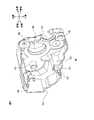
2.ドラムカートリッジ
図2および図3に示すように、ドラムカートリッジ18は、ドラムフレーム51を備えている。
In this way, the paper S is fed from the paper placement unit 9, passes between the photosensitive drum 20 and the transfer roller 21 (nip portion), and then passes between the heating roller 38 and the pressure roller 39. After that, the paper is transported through a substantially C-shaped transport path in side view so that the paper is discharged onto the paper discharge tray 41.
2. Drum Cartridge As shown in FIGS. 2 and 3, the drum cartridge 18 includes a drum frame 51.

なお、以下のドラムカートリッジ18の説明において、方向について言及するときには、感光ドラム20が配置されている側を後側とし、スコロトロン型帯電器22が配置されている側を上側とする。すなわち、ドラムカートリッジ18に関する上下前後方向は、プリンタ1に関する上下前後方向と若干異なり、ドラムカートリッジ18は、その後側がプリンタ1の後上側、その前側がプリンタ1の前下側となるように、プリンタ1に装着されている。   In the following description of the drum cartridge 18, when referring to the direction, the side on which the photosensitive drum 20 is disposed is the rear side, and the side on which the scorotron charger 22 is disposed is the upper side. That is, the up / down / front / rear direction with respect to the drum cartridge 18 is slightly different from the up / down / front / rear direction with respect to the printer 1. It is attached to.

ドラムフレーム51は、左右1対の側壁52、下壁53、前壁54、後壁55および上壁56を備えている。   The drum frame 51 includes a pair of left and right side walls 52, a lower wall 53, a front wall 54, a rear wall 55, and an upper wall 56.

側壁52は、前後方向に延びる略平板形状に形成されている。側壁52は、その後側半分を構成する後側部分57と、その前側半分を構成する前側部分58とを一体的に備えている。   The side wall 52 is formed in a substantially flat plate shape extending in the front-rear direction. The side wall 52 is integrally provided with a rear portion 57 constituting the rear half and a front portion 58 constituting the front half thereof.

後側部分57は、上下方向に延びる側面視略矩形状に形成されている。右側の側壁52の後側部分57には、ワイヤ電極62と、グリッド電極63とが設けられている。   The rear portion 57 is formed in a substantially rectangular shape in a side view extending in the vertical direction. A wire electrode 62 and a grid electrode 63 are provided on the rear portion 57 of the right side wall 52.

ワイヤ電極62は、後側部分57の前上側端部に配置され、前後方向に延びる略直線形状の接点64を有している。ワイヤ電極62は、帯電ワイヤ23に電気的に接続されている。   The wire electrode 62 is disposed at the front upper end of the rear portion 57 and has a substantially linear contact 64 extending in the front-rear direction. The wire electrode 62 is electrically connected to the charging wire 23.

グリッド電極63は、後側部分57の後上側端部に配置され、上下方向に長手の側面視略矩形の平板形状に形成されている。グリッド電極63は、グリッド24に電気的に接続されている。   The grid electrode 63 is disposed at the rear upper end portion of the rear portion 57, and is formed in a flat plate shape that is substantially rectangular in a side view that is long in the vertical direction. The grid electrode 63 is electrically connected to the grid 24.

前側部分58は、後側部分57の下側の前端部から連続して前側へ延びる側面視略矩形状に形成されている。   The front portion 58 is formed in a substantially rectangular shape in side view extending continuously from the front end on the lower side of the rear portion 57 to the front side.

下壁53は、前後左右に延び、両側壁52の下端部間に架設される略平板形状に形成されている。   The lower wall 53 extends in the front-rear and left-right directions, and is formed in a substantially flat plate shape that is installed between the lower ends of the side walls 52.

前壁54は、下壁53の前端部から連続して上側へ延び、両側壁52の前端部間に架設される略平板形状に形成されている。   The front wall 54 continuously extends from the front end portion of the lower wall 53 and is formed in a substantially flat plate shape extending between the front end portions of the side walls 52.

後壁55は、両側壁52の後端部間に架設されている。後壁55は、下壁53の後端部から連続して上側へ延び、上側へ向かうに従って前側へ湾曲される略平板形状に形成されている。後壁55の内側(前側)には、上記した転写ローラ21が回転可能に支持されている。   The rear wall 55 is constructed between the rear ends of the side walls 52. The rear wall 55 is formed in a substantially flat plate shape that continuously extends upward from the rear end portion of the lower wall 53 and is curved forward as it goes upward. The transfer roller 21 described above is rotatably supported on the inner side (front side) of the rear wall 55.

上壁56は、ドラムフレーム51の上端部に設けられ、後壁55の上端部から前側へ延びる略平板形状に形成されている。上壁56の内側(下側)には、上記したスコロトロン型帯電器22が支持されている。   The upper wall 56 is provided in the upper end part of the drum frame 51, and is formed in the substantially flat plate shape extended from the upper end part of the rear wall 55 to the front side. The scorotron charger 22 is supported on the inner side (lower side) of the upper wall 56.

そして、ドラムカートリッジ18において、下壁53の後端部、後壁55、上壁56、および、両側壁52の後側部分57によって、感光ドラム20を収容するドラム収容部59が区画されている。   In the drum cartridge 18, a drum accommodating portion 59 that accommodates the photosensitive drum 20 is defined by the rear end portion of the lower wall 53, the rear wall 55, the upper wall 56, and the rear portions 57 of the both side walls 52. .

感光ドラム20は、ドラム軸S1の左右両端部において、それぞれ、対応する側壁52の後側部分57に回転可能に支持されている。なお、ドラム軸S1の左右方向端部は、側壁52の後側部分57を貫通して左右方向外側へ突出されている。   The photosensitive drums 20 are rotatably supported by the rear portions 57 of the corresponding side walls 52 at the left and right ends of the drum shaft S1, respectively. In addition, the left-right direction edge part of drum axis | shaft S1 penetrates the rear side part 57 of the side wall 52, and protrudes in the left-right direction outer side.

また、ドラムカートリッジ18において、下壁53、前壁54、および、両側壁52の前側部分58によって、現像カートリッジ19が装着されるカートリッジ装着部60が区画されている。カートリッジ装着部60には、被検知ギア露出開口61が形成されている。   In the drum cartridge 18, the lower wall 53, the front wall 54, and the front portions 58 of the side walls 52 define a cartridge mounting portion 60 in which the developing cartridge 19 is mounted. A detected gear exposure opening 61 is formed in the cartridge mounting portion 60.

被検知ギア露出開口61は、ドラムフレーム51の左端部の前下側端部に配置されている。被検知ギア露出開口61は、下壁53の前端部と前壁54の下端部とにわたって、前後方向に延びる平面視略矩形状に貫通形成されている。
3.現像カートリッジ
現像カートリッジ19は、上記し、図4に示すように、現像フレーム25と、現像フレーム25の左側に配置される駆動ユニット70を備えている。なお、現像フレーム25の右側には、現像カートリッジ19に電力を供給するための給電ユニット(図示せず)が設けられている。
The detected gear exposure opening 61 is arranged at the front lower end of the left end of the drum frame 51. The detected gear exposure opening 61 is formed through the front end portion of the lower wall 53 and the lower end portion of the front wall 54 in a substantially rectangular shape in plan view extending in the front-rear direction.
3. Developer Cartridge Developer cartridge 19 includes developer frame 25 and drive unit 70 disposed on the left side of developer frame 25 as described above and shown in FIG. A power supply unit (not shown) for supplying power to the developing cartridge 19 is provided on the right side of the developing frame 25.

なお、以下の現像カートリッジ19の説明において、方向について言及するときには、現像ローラ34が配置されている側を後側とし、層厚規制ブレード35が配置されている側を上側とする。すなわち、現像カートリッジ19に関する上下前後方向は、プリンタ1に関する上下前後方向と若干異なり、現像カートリッジ19は、その後側がプリンタ1の後上側、その前側がプリンタ1の前下側となるように、プリンタ1に装着されている。
(1)現像フレーム
現像フレーム25は、左右方向に延びる略ボックス形状に形成されている。詳しくは、現像フレーム25は、左右1対の側壁71と、下壁72と、前壁73と、上壁74とを備えている。
In the following description of the developing cartridge 19, when referring to the direction, the side on which the developing roller 34 is disposed is the rear side, and the side on which the layer thickness regulating blade 35 is disposed is the upper side. That is, the up / down / front / rear direction with respect to the developing cartridge 19 is slightly different from the up / down / front / rear direction with respect to the printer 1. It is attached to.
(1) Development frame The development frame 25 is formed in a substantially box shape extending in the left-right direction. Specifically, the developing frame 25 includes a pair of left and right side walls 71, a lower wall 72, a front wall 73, and an upper wall 74.

1対の側壁71は、トナー収容室26を挟むように、互いに左右方向に間隔を隔てて対向配置されている。なお、以下の説明においては、駆動ユニット70を支持する左側の側壁71を詳しく説明し、右側の側壁71の説明を省略する。また、左側の側壁71を単に側壁71と記載する。   The pair of side walls 71 are opposed to each other with a space in the left-right direction so as to sandwich the toner storage chamber 26. In the following description, the left side wall 71 that supports the drive unit 70 will be described in detail, and the description of the right side wall 71 will be omitted. Further, the left side wall 71 is simply referred to as a side wall 71.

側壁71は、前後方向に延びる側面視略矩形状に形成されている。側壁71には、シール収容部75と、アジテータ軸露出部76と、アイドルギア支持部77と、被検知ギア支持部78と、第2被係合部の一例としての駆動検査用被係合部79と、被係合ボス80とが形成されている。   The side wall 71 is formed in a substantially rectangular shape in side view extending in the front-rear direction. The side wall 71 includes a seal housing portion 75, an agitator shaft exposure portion 76, an idle gear support portion 77, a detected gear support portion 78, and an engaged portion for drive inspection as an example of a second engaged portion. 79 and an engaged boss 80 are formed.

シール収容部75は、側壁71の後端部において、現像室27に対応するように、側壁71の左面から左側へ膨出し、左端部が閉鎖された略筒形状に形成されている。シール収容部75の左壁には、現像ローラ軸S4の左端部を露出させる現像ローラ軸露出穴(図示せず)と、供給ローラ軸S3の左端部を露出させる供給ローラ軸露出穴(図示せず)とが貫通形成されている。供給ローラ軸露出穴(図示せず)内には、供給ローラ軸S3の外周面と供給ローラ軸露出穴(図示せず)の内周面との間をシールするシール部材(図示せず)が設けられている。   The seal housing portion 75 is formed in a substantially cylindrical shape that bulges from the left surface of the side wall 71 to the left side and closes the left end portion so as to correspond to the developing chamber 27 at the rear end portion of the side wall 71. On the left wall of the seal housing portion 75, a developing roller shaft exposure hole (not shown) for exposing the left end portion of the developing roller shaft S4 and a supply roller shaft exposure hole (not shown) for exposing the left end portion of the supply roller shaft S3 are shown. Z). In the supply roller shaft exposure hole (not shown), there is a seal member (not shown) that seals between the outer peripheral surface of the supply roller shaft S3 and the inner peripheral surface of the supply roller shaft exposure hole (not shown). Is provided.

なお、シール収容部75から左側へ露出された現像ローラ軸S4の左端部には、ギア嵌合部S41と、カラー嵌合部S42とが設けられている。   A gear fitting portion S41 and a collar fitting portion S42 are provided at the left end portion of the developing roller shaft S4 exposed to the left from the seal housing portion 75.

ギア嵌合部S41は、断面視略D字形状に形成されている。   The gear fitting portion S41 is formed in a substantially D shape when viewed in cross section.

カラー嵌合部S42は、ギア嵌合部S41の左面から左側へ延び、ギア嵌合部S41よりも小径な略円柱形状に形成されている。   The collar fitting portion S42 extends from the left surface of the gear fitting portion S41 to the left side, and is formed in a substantially cylindrical shape having a smaller diameter than the gear fitting portion S41.

また、シール収容部75から左側へ露出された供給ローラ軸S3の左端部は、断面視略D字形状に形成されている。   Further, the left end portion of the supply roller shaft S3 exposed to the left side from the seal housing portion 75 is formed in a substantially D shape in sectional view.

アジテータ軸露出部76は、シール収容部75の前側において、側面視略円筒形状に形成されている。   The agitator shaft exposing portion 76 is formed in a substantially cylindrical shape in a side view on the front side of the seal housing portion 75.

アジテータ軸露出部76内には、図10に示すように、側壁71を貫通するアジテータ軸挿通穴88が形成されている。また、アジテータ軸露出部76内には、側壁71の左側において、アジテータ軸シール89が設けられている。   As shown in FIG. 10, an agitator shaft insertion hole 88 that penetrates the side wall 71 is formed in the agitator shaft exposed portion 76. An agitator shaft seal 89 is provided in the agitator shaft exposed portion 76 on the left side of the side wall 71.

アジテータ軸挿通穴88は、アジテータ軸S2の左右方向端部の外径よりも大径な内径を有する側面視略円形状に形成されている。そして、アジテータ軸S2の左端部は、アジテータ軸挿通穴88を介して、側壁71から左側へ露出されている。   The agitator shaft insertion hole 88 is formed in a substantially circular shape in a side view having an inner diameter larger than the outer diameter of the end portion in the left-right direction of the agitator shaft S2. The left end portion of the agitator shaft S <b> 2 is exposed to the left from the side wall 71 through the agitator shaft insertion hole 88.

なお、アジテータ軸挿通穴88から左側へ露出されたアジテータ軸S2の左端部は、断面視略D字形状に形成されている。また、アジテータ軸挿通穴88から左側へ露出されたアジテータ軸S2の左面には、その周縁部から径方向内側へ凹むように、側面視略半円形状の凹部S21が形成されている。   In addition, the left end portion of the agitator shaft S2 exposed to the left from the agitator shaft insertion hole 88 is formed in a substantially D shape in a sectional view. Further, the left surface of the agitator shaft S2 exposed to the left from the agitator shaft insertion hole 88 is formed with a substantially semicircular recess S21 in a side view so as to be recessed inward in the radial direction from the peripheral portion thereof.

アジテータ軸シール89は、スポンジなどの弾性材料から左右方向に厚みを有する略円環形状に形成され、アジテータ軸S2に、断面視略D字形状の部分の右側において外嵌(アジテータ軸S2の径方向外側から嵌合)されるとともに、アジテータ軸露出部76内に嵌合されている。   The agitator shaft seal 89 is formed in an approximately annular shape having a thickness in the left-right direction from an elastic material such as sponge, and is fitted onto the agitator shaft S2 on the right side of the substantially D-shaped portion in cross section (the diameter of the agitator shaft S2). And is fitted in the agitator shaft exposed portion 76.

図4に示すように、アイドルギア支持部77は、アジテータ軸露出部76の前上側において、側壁71の左面から左側へ突出する略円柱形状に形成されている。   As shown in FIG. 4, the idle gear support 77 is formed in a substantially cylindrical shape that protrudes from the left surface of the side wall 71 to the left on the front upper side of the agitator shaft exposure portion 76.

被検知ギア支持部78は、アイドルギア支持部77の前下側において、側壁71の左面から左側へ突出する側面視略十字形の柱形状に形成されている。被検知ギア支持部78は、アイドルギア支持部77よりも左側へ突出されている。   The detected gear support portion 78 is formed in a substantially cross-shaped column shape in a side view protruding from the left surface of the side wall 71 to the left side on the front lower side of the idle gear support portion 77. The detected gear support 78 protrudes to the left of the idle gear support 77.

駆動検査用被係合部79は、アイドルギア支持部77と被検知ギア支持部78との間において、側壁71の左面から左側へ突出する略角柱形状に形成されている。また、駆動検査用被係合部79の左面は、後上側へ向かうに従って左側へ傾斜している。駆動検査用被係合部79の左端部は、被検知ギア支持部78の左端部よりも右側に配置されている。   The drive inspection engaged portion 79 is formed in a substantially prismatic shape protruding from the left surface of the side wall 71 to the left side between the idle gear support portion 77 and the detected gear support portion 78. In addition, the left surface of the drive inspection engaged portion 79 is inclined to the left side toward the rear upper side. The left end portion of the drive inspection engaged portion 79 is disposed on the right side of the left end portion of the detected gear support portion 78.

被係合ボス80は、駆動検査用被係合部79の下側において、側壁71の左面から左側へ突出する略角柱形状に形成されている。駆動検査用被係合部79の左端部は、被検知ギア支持部78の左端部よりも右側に配置されている。   The engaged boss 80 is formed in a substantially prismatic shape protruding from the left surface of the side wall 71 to the left side below the engaged portion 79 for driving inspection. The left end portion of the drive inspection engaged portion 79 is disposed on the right side of the left end portion of the detected gear support portion 78.

また、側壁71には、複数(2つ)の被係止部68と、複数(2つ)の螺合部69とを備えている。   Further, the side wall 71 includes a plurality (two) of locked portions 68 and a plurality (two) of screwed portions 69.

複数の被係止部68は、被検知ギア支持部78の上側と、アジテータ軸露出部76の下側(図6参照)とに1つずつ設けられている。   The plurality of locked portions 68 are provided one by one on the upper side of the detected gear support portion 78 and on the lower side of the agitator shaft exposing portion 76 (see FIG. 6).

上側の被係止部68は、被検知ギア支持部78の上側において、側壁71の左面から左側へ向かって突出し、その左端部において上側へ屈曲する略鉤形状に形成されている。   The upper locked portion 68 is formed in a substantially bowl shape that protrudes from the left surface of the side wall 71 toward the left side above the detected gear support portion 78 and bends upward at the left end portion thereof.

下側の被係止部68は、アジテータ軸露出部76の右端部において、その下面から下側へ突出し、前後方向に延びる突条である(図6参照)。   The lower locked portion 68 is a protrusion that protrudes downward from the lower surface of the agitator shaft exposed portion 76 and extends in the front-rear direction (see FIG. 6).

複数の螺合部69は、側壁71の後上側端部と後下側端部とに1つずつ設けられている。螺合部69は、側壁71の左面から左側へ向かって突出する略円柱形状に形成されている。螺合部69には、その左面から右側へ凹むように、ねじ穴66が形成されている。また、下側の螺合部69には、縮径部67が形成されている。   The plurality of screwing portions 69 are provided one for each of the rear upper end and the rear lower end of the side wall 71. The threaded portion 69 is formed in a substantially cylindrical shape protruding from the left surface of the side wall 71 toward the left side. A screw hole 66 is formed in the screwing portion 69 so as to be recessed from the left surface to the right side. Further, a reduced diameter portion 67 is formed in the lower screwing portion 69.

縮径部67は、下側の螺合部69の左端部において、ねじ穴66の周縁部から左側へ延びる略円筒形状に形成されている。縮径部67の外径は、下側の螺合部69における縮径部67より右側の部分の外径よりも小径である。   The reduced diameter portion 67 is formed in a substantially cylindrical shape extending leftward from the peripheral edge portion of the screw hole 66 at the left end portion of the lower screwing portion 69. The outer diameter of the reduced diameter portion 67 is smaller than the outer diameter of the portion on the right side of the reduced diameter portion 67 in the lower threaded portion 69.

下壁72は、前後方向に延びる略平板形状に形成され、その左右方向両端部において、両側壁71の下端部に連続されている(図5参照)。   The lower wall 72 is formed in a substantially flat plate shape extending in the front-rear direction, and is continuous with the lower ends of the side walls 71 at both ends in the left-right direction (see FIG. 5).

前壁73は、下壁72の前端部から連続して上側へ延びる略平板形状に形成され、その左右方向両端部において、両側壁71の前端部に連続されている。   The front wall 73 is formed in a substantially flat plate shape extending continuously upward from the front end portion of the lower wall 72, and is continuous with the front end portions of the side walls 71 at both left and right end portions thereof.

上壁74は、前後左右に延びる略平板形状に形成され、両側壁71および前壁73の上端部に上側から対向配置されている。上壁74は、その周縁部において、両側壁71および前壁73の上端部に対して、溶着などの方法により固定されている。
(2)駆動ユニット
駆動ユニット70は、軸受部材81と、ギア列83(図5参照)と、カラー部材82と、被覆部材の一例としてのギアカバー84とを備えている。
(2−1)軸受部材
軸受部材81は、シール収容部75の左側において、現像フレーム25に支持されている。軸受部材81は、上下方向に延びる略平板形状に形成されている。軸受部材81には、現像ローラ軸挿通穴85と、供給ローラ軸挿通穴86とが形成されている。また、軸受部材81は、カップリング支持部87を備えている。
The upper wall 74 is formed in a substantially flat plate shape extending in the front-rear and left-right directions, and is disposed so as to face the upper ends of the side walls 71 and the front wall 73 from above. The upper wall 74 is fixed to the upper end portions of the side walls 71 and the front wall 73 by a method such as welding at the periphery.
(2) Drive Unit The drive unit 70 includes a bearing member 81, a gear train 83 (see FIG. 5), a collar member 82, and a gear cover 84 as an example of a covering member.
(2-1) Bearing Member The bearing member 81 is supported by the developing frame 25 on the left side of the seal housing portion 75. The bearing member 81 is formed in a substantially flat plate shape extending in the vertical direction. The bearing member 81 is formed with a developing roller shaft insertion hole 85 and a supply roller shaft insertion hole 86. Further, the bearing member 81 includes a coupling support portion 87.

現像ローラ軸挿通穴85は、軸受部材81の後端部において、側面視略円形状に貫通形成されている。現像ローラ軸挿通穴85の内径は、現像ローラ軸S4の外径と略同径(わずかに大径)に形成されている。   The developing roller shaft insertion hole 85 is formed in a substantially circular shape in a side view at the rear end portion of the bearing member 81. The inner diameter of the developing roller shaft insertion hole 85 is substantially the same diameter (slightly larger) as the outer diameter of the developing roller shaft S4.

供給ローラ軸挿通穴86は、現像ローラ軸挿通穴85の前下側において、側面視略円形状に貫通形成されている。供給ローラ軸挿通穴86の内径は、供給ローラ軸S3の外径と略同径(わずかに大径)に形成されている。   The supply roller shaft insertion hole 86 is formed in a substantially circular shape in a side view on the front lower side of the developing roller shaft insertion hole 85. The inner diameter of the supply roller shaft insertion hole 86 is formed to be substantially the same diameter (slightly larger) as the outer diameter of the supply roller shaft S3.

カップリング支持部87は、現像ローラ軸挿通穴85の前側、かつ、供給ローラ軸挿通穴86の上側において、軸受部材81の左面から左側へ突出する略円筒形状に形成されている。
(2−2)ギア列
ギア列83は、図4および図5に示すように、現像カップリング91、現像ギア92、供給ギア93、駆動伝達部材の一例としてのアイドルギア94、アジテータギア95、および、被検知部材の一例としての被検知ギア96を備えている。
The coupling support portion 87 is formed in a substantially cylindrical shape protruding from the left surface of the bearing member 81 to the left side on the front side of the developing roller shaft insertion hole 85 and on the upper side of the supply roller shaft insertion hole 86.
(2-2) Gear train As shown in FIGS. 4 and 5, the gear train 83 includes a development coupling 91, a development gear 92, a supply gear 93, an idle gear 94 as an example of a drive transmission member, an agitator gear 95, A detected gear 96 is provided as an example of a detected member.

現像カップリング91は、左右方向に延びる略円柱形状に形成されている。現像カップリング91は、大径ギア部97と、小径ギア部98と、カップリング部99とを一体的に有している。   The development coupling 91 is formed in a substantially cylindrical shape extending in the left-right direction. The development coupling 91 integrally includes a large diameter gear portion 97, a small diameter gear portion 98, and a coupling portion 99.

大径ギア部97は、現像カップリング91の右端部に設けられ、左右方向に厚みを有する略円板形状に形成されている。なお、大径ギア部97の径方向中央には、カップリング支持部87の外径よりも大径(ほぼ同径)な貫通穴(図示せず)が形成されている。また、大径ギア部97の周面には、その全周にわたってギア歯が形成されている。   The large-diameter gear portion 97 is provided at the right end portion of the development coupling 91 and is formed in a substantially disc shape having a thickness in the left-right direction. A through hole (not shown) having a larger diameter (substantially the same diameter) as the outer diameter of the coupling support portion 87 is formed at the radial center of the large diameter gear portion 97. Further, gear teeth are formed on the circumferential surface of the large-diameter gear portion 97 over the entire circumference.

小径ギア部98は、大径ギア部97の貫通穴(図示せず)を囲うように、大径ギア部97の左面から左側へ突出する略円筒形状に形成されている。小径ギア部98の外径は、大径ギア部97の外径よりも小径である。小径ギア部98の内径は、大径ギア部97の貫通穴(図示せず)よりも大径である。また、小径ギア部98の中心軸線は、大径ギア部97の中心軸線と一致している。小径ギア部98の外周面には、その全周にわたってギア歯が形成されている。小径ギア部98の歯数は、大径ギア部97の歯数よりも少ない。   The small diameter gear portion 98 is formed in a substantially cylindrical shape protruding from the left surface of the large diameter gear portion 97 to the left side so as to surround a through hole (not shown) of the large diameter gear portion 97. The outer diameter of the small diameter gear portion 98 is smaller than the outer diameter of the large diameter gear portion 97. The inner diameter of the small diameter gear portion 98 is larger than the through hole (not shown) of the large diameter gear portion 97. Further, the center axis of the small diameter gear portion 98 coincides with the center axis of the large diameter gear portion 97. Gear teeth are formed on the outer peripheral surface of the small-diameter gear portion 98 over the entire circumference. The number of teeth of the small diameter gear portion 98 is smaller than the number of teeth of the large diameter gear portion 97.

カップリング部99は、小径ギア部98の径方向内側に配置されている。カップリング部99は、大径ギア部97の左面において、貫通穴(図示せず)の周縁部から連続して左側へ突出し、左端部が閉鎖された略円筒形状に形成されている。カップリング部99の外径は、小径ギア部98の内径よりも小径である。カップリング部99の内径は、大径ギア部97の貫通穴(図示せず)の内径と同径である。また、カップリング部99の中心軸線は、大径ギア部97の中心軸線と一致している。また、カップリング部99の左面には、結合凹部100が形成されている。   The coupling part 99 is disposed on the radially inner side of the small diameter gear part 98. The coupling part 99 is formed in a substantially cylindrical shape, which protrudes to the left continuously from the peripheral part of the through hole (not shown) on the left surface of the large-diameter gear part 97 and whose left end is closed. The outer diameter of the coupling portion 99 is smaller than the inner diameter of the small diameter gear portion 98. The inner diameter of the coupling portion 99 is the same as the inner diameter of a through hole (not shown) of the large diameter gear portion 97. Further, the central axis of the coupling portion 99 coincides with the central axis of the large diameter gear portion 97. A coupling recess 100 is formed on the left surface of the coupling portion 99.

結合凹部100は、現像カップリング91の左面から右側へ凹むように、現像カップリング91の径方向に延びる側面視略長穴形状に形成されている。結合凹部100には、本体ケーシング2内に設けられる本体カップリング46(図5参照)の結合凸部47(図5参照)が駆動伝達可能に嵌合される。   The coupling recess 100 is formed in a substantially long hole shape in side view extending in the radial direction of the development coupling 91 so as to be recessed from the left surface of the development coupling 91 to the right side. The coupling concave portion 100 is fitted with a coupling convex portion 47 (see FIG. 5) of a main body coupling 46 (see FIG. 5) provided in the main body casing 2 so as to be able to transmit drive.

現像ギア92は、左右方向に延びる略円筒形状に形成されている。現像ギア92は、ギア部101と、カラー挿入部102とを一体的に有している。   The developing gear 92 is formed in a substantially cylindrical shape extending in the left-right direction. The developing gear 92 integrally includes a gear portion 101 and a collar insertion portion 102.

ギア部101は、現像ギア92の右端部に設けられ、左右方向に厚みを有する略円板形状に形成されている。なお、ギア部101の径方向中央には、現像ローラ軸S4の左端部を受け入れ可能な側面視略D字形状の貫通穴(図示せず)が形成されている。ギア部101の周面には、その全周にわたってギア歯が形成されている。   The gear portion 101 is provided at the right end portion of the developing gear 92 and is formed in a substantially disc shape having a thickness in the left-right direction. Note that a substantially D-shaped through-hole (not shown) in a side view capable of receiving the left end portion of the developing roller shaft S4 is formed at the radial center of the gear portion 101. Gear teeth are formed on the circumferential surface of the gear portion 101 over the entire circumference.

カラー挿入部102は、ギア部101の左端部から連続して左側へ突出する略円筒形状に形成されている。カラー挿入部102の外径は、ギア部101の外径よりも小径である。カラー挿入部102の中心軸線は、ギア部101の中心軸線と一致している。   The collar insertion portion 102 is formed in a substantially cylindrical shape that protrudes leftward continuously from the left end portion of the gear portion 101. The outer diameter of the collar insertion portion 102 is smaller than the outer diameter of the gear portion 101. The central axis of the color insertion portion 102 matches the central axis of the gear portion 101.

供給ギア93は、左右方向に厚みを有する略円板形状に形成されている。供給ギア93の径方向中央には、供給ローラ軸S3の左端部を受け入れ可能な側面視略D字形状の供給ローラ軸嵌合穴103が貫通形成されている。供給ギア93の周面には、その全周にわたって、左右方向に延びるギア歯が形成されている。   The supply gear 93 is formed in a substantially disc shape having a thickness in the left-right direction. In the center of the supply gear 93 in the radial direction, a supply roller shaft fitting hole 103 having a substantially D shape in a side view capable of receiving the left end portion of the supply roller shaft S3 is formed through. On the peripheral surface of the supply gear 93, gear teeth extending in the left-right direction are formed over the entire periphery.

アイドルギア94は、左右方向に延びる略円筒形状に形成されている。アイドルギア94は、大径部104と、小径部105とを一体的に有している。   The idle gear 94 is formed in a substantially cylindrical shape that extends in the left-right direction. The idle gear 94 integrally has a large diameter portion 104 and a small diameter portion 105.

大径部104は、アイドルギア94の左端部に設けられ、左右方向に厚みを有する略円板形状に形成されている。大径部104の径方向中央には、側面視略円形状の嵌合穴106が貫通形成されている。大径部104の外径は、カップリング部99の小径ギア部98の外径よりも小径である。大径部104の周面には、その全周にわたって、ギア歯が形成されている。大径部104の歯数は、カップリング部99の小径ギア部98の歯数よりも少ない。   The large diameter portion 104 is provided at the left end portion of the idle gear 94 and is formed in a substantially disc shape having a thickness in the left-right direction. A fitting hole 106 having a substantially circular shape in side view is formed through the center of the large diameter portion 104 in the radial direction. The outer diameter of the large diameter portion 104 is smaller than the outer diameter of the small diameter gear portion 98 of the coupling portion 99. Gear teeth are formed on the circumferential surface of the large diameter portion 104 over the entire circumference. The number of teeth of the large diameter portion 104 is smaller than the number of teeth of the small diameter gear portion 98 of the coupling portion 99.

小径部105は、大径部104の右面において、嵌合穴106の周縁部から右側へ延びる略円筒形状に形成されている。小径部105の外径は、大径部104の外径よりも小径である。小径部105は、大径部104と中心軸線を共有している。小径部105の周面には、その全周にわたって、ギア歯が形成されている。小径部105の歯数は、大径部104の歯数よりも少ない。   The small diameter portion 105 is formed in a substantially cylindrical shape extending rightward from the peripheral edge portion of the fitting hole 106 on the right surface of the large diameter portion 104. The outer diameter of the small diameter portion 105 is smaller than the outer diameter of the large diameter portion 104. The small diameter portion 105 shares the central axis with the large diameter portion 104. Gear teeth are formed on the circumferential surface of the small diameter portion 105 over the entire circumference. The number of teeth of the small diameter portion 105 is smaller than the number of teeth of the large diameter portion 104.

アジテータギア95は、左右方向に厚みを有する略円板形状に形成されている。アジテータギア95の径方向中央には、アジテータ軸S2の左端部を受け入れ可能な側面視略D字形状のアジテータ軸嵌合穴107が貫通形成されている。アジテータギア95の周面には、その全周にわたって、ギア歯が形成されている。また、アジテータギア95には、アジテータ軸嵌合穴107内において、突起108が設けられている。   The agitator gear 95 is formed in a substantially disc shape having a thickness in the left-right direction. In the center of the agitator gear 95 in the radial direction, an agitator shaft fitting hole 107 having a substantially D shape in a side view capable of receiving the left end portion of the agitator shaft S2 is formed through. Gear teeth are formed on the circumferential surface of the agitator gear 95 over the entire circumference. The agitator gear 95 is provided with a protrusion 108 in the agitator shaft fitting hole 107.

突起108は、アジテータ軸嵌合穴107の左端部において、その内周面から内側(アジテータ軸嵌合穴107の内側)へ向かって突出する側面視略半円形状に形成されている。突起108の外径は、アジテータ軸S2の凹部S21の内径よりも小径である。   The protrusion 108 is formed at the left end portion of the agitator shaft fitting hole 107 in a substantially semicircular shape in side view protruding from the inner peripheral surface thereof toward the inside (inside the agitator shaft fitting hole 107). The outer diameter of the protrusion 108 is smaller than the inner diameter of the recess S21 of the agitator shaft S2.

被検知ギア96は、左右方向に厚みを有する略半円板形状に形成されている。詳しくは、図4および図11に示すように、被検知ギア96は、軸部111と、歯部112と、第2被検知部の一例としての第1当接部113と、第1被検知部の一例としての第2当接部114と、第1係合部115と、第2係合部116とを備えている。   The detected gear 96 is formed in a substantially semicircular shape having a thickness in the left-right direction. Specifically, as shown in FIGS. 4 and 11, the detected gear 96 includes a shaft part 111, a tooth part 112, a first contact part 113 as an example of a second detected part, and a first detected object. A second abutting portion 114, a first engaging portion 115, and a second engaging portion 116 as an example of the portion are provided.

軸部111は、被検知ギア96の径方向中央に配置され、左右方向に延びる略円筒形状に形成されている。軸部111の内径は、被検知ギア支持部78の外径よりも大径(略同径)である。   The shaft portion 111 is disposed at the center of the detected gear 96 in the radial direction and is formed in a substantially cylindrical shape extending in the left-right direction. The inner diameter of the shaft portion 111 is larger than the outer diameter of the detected gear support portion 78 (substantially the same diameter).

歯部112は、被検知ギア96の外形形状を形成し、左右方向に厚みを有する略半円板形状に形成されている。歯部112の左右方向長さは、軸部111の左右方向長さよりも短い。歯部112の周面には、左右方向に延びるギア歯が形成されている。   The tooth part 112 forms the outer shape of the gear 96 to be detected, and is formed in a substantially semicircular disk shape having a thickness in the left-right direction. The length of the tooth portion 112 in the left-right direction is shorter than the length of the shaft portion 111 in the left-right direction. Gear teeth extending in the left-right direction are formed on the peripheral surface of the tooth portion 112.

第1当接部113は、左側面視時計回り方向(第1方向)において、歯部112の上流側端部の上流側に連続されている。つまり、第1当接部113は、左右方向において歯部112と同じ位置にある。第1当接部113は、軸部111から径方向外側(被検知ギア96の径方向における外側。以下、被検知ギア96の説明において同じ。)へ向かって延び、左側面視時計回り方向上流側へ屈曲される略平板形状に形成されている。第1当接部113の左右方向長さは、歯部112の左右方向長さよりも長く、軸部111の左右方向長さよりも短い。   The first contact portion 113 is continuous to the upstream side of the upstream end portion of the tooth portion 112 in the clockwise direction (first direction) when viewed from the left side. That is, the 1st contact part 113 exists in the same position as the tooth | gear part 112 in the left-right direction. The first contact portion 113 extends from the shaft portion 111 toward the radially outer side (the outer side in the radial direction of the detected gear 96; hereinafter the same in the description of the detected gear 96), and is upstream in the clockwise direction when viewed from the left side. It is formed in a substantially flat plate shape bent to the side. The length in the left-right direction of the first contact portion 113 is longer than the length in the left-right direction of the tooth portion 112 and shorter than the length in the left-right direction of the shaft portion 111.

第2当接部114は、左側面視時計回り方向において、歯部112の下流側端部の下流側に連続されている。つまり、第2当接部114は、左右方向において歯部112と同じ位置にある。第2当接部114は、軸部111から径方向外側へ向かって延びる略平板形状に形成されている。また、第2当接部114の径方向外側端部には、歯部112のギア歯に連続するように、左右方向に延びるギア歯が形成されている。これにより、第2当接部114は、歯部112とともに受動部110を構成する。また、第2当接部114の左右方向長さは、第1当接部113の左右方向長さと同じ長さである。   The second contact portion 114 is continuous to the downstream side of the downstream end portion of the tooth portion 112 in the clockwise direction in the left side view. That is, the 2nd contact part 114 exists in the same position as the tooth | gear part 112 in the left-right direction. The second contact portion 114 is formed in a substantially flat plate shape extending from the shaft portion 111 toward the radially outer side. In addition, gear teeth extending in the left-right direction are formed on the radially outer end of the second contact portion 114 so as to be continuous with the gear teeth of the tooth portion 112. Thereby, the second contact portion 114 constitutes the passive portion 110 together with the tooth portion 112. Further, the length of the second contact portion 114 in the left-right direction is the same as the length of the first contact portion 113 in the left-right direction.

第1係合部115は、軸部111の左端部から径方向外側(軸部111に対して歯部112の反対側)へ向かって、屈曲しながら突出する略杆形状に形成されている。詳しくは、第1係合部115は、左右方向に投影したときにその軸部111側の端部が第1当接部113と重なるように、軸部111の左端部から径方向外側へ向かってわずかに突出し、左側面視時計回り方向上流側へ第1当接部113と略直角をなすように屈曲して直線状に延び、その先端部(遊端部)において、さらに左側面視時計回り方向上流側へ湾曲されている。また、第1係合部115には、接触端部の一例としての摺擦部117が設けられている。   The first engaging portion 115 is formed in a substantially bowl shape that protrudes while being bent from the left end portion of the shaft portion 111 toward the radially outer side (the opposite side of the tooth portion 112 with respect to the shaft portion 111). Specifically, the first engagement portion 115 is directed radially outward from the left end portion of the shaft portion 111 so that the end portion on the shaft portion 111 side overlaps the first contact portion 113 when projected in the left-right direction. Projecting slightly and bent in a direction substantially perpendicular to the first contact portion 113 in the clockwise direction in the left side view and extending in a straight line, and at the tip portion (free end portion), the left side view clock Curved upstream in the rotational direction. The first engagement portion 115 is provided with a rubbing portion 117 as an example of a contact end portion.

摺擦部117は、第1係合部115の先端部において、径方向外側へ膨出する側面視略円弧形状に形成されている。   The rubbing portion 117 is formed in a substantially arc shape in a side view that bulges radially outward at the distal end portion of the first engaging portion 115.

第2係合部116は、軸部111の右端部から径方向外側へ向かって、屈曲しながら突出する略杆形状に形成されている。詳しくは、第2係合部116は、第1当接部113と第2当接部114との間において歯部112の反対側に設けられ、軸部111の右端部から径方向外側へ向かってわずかに突出し、左側面視時計回り方向上流側へ屈曲して第2当接部114と略平行するように直線状に延び、その先端部(遊端部)において、さらに左側面視時計回り方向上流側へ湾曲されている。
(2−3)ギア列の組み付け状態
図4および図5に示すように、現像カップリング91は、軸受部材81のカップリング支持部87に回転可能に支持されている。
The second engagement portion 116 is formed in a substantially bowl shape that protrudes while being bent from the right end portion of the shaft portion 111 toward the radially outer side. Specifically, the second engagement portion 116 is provided on the opposite side of the tooth portion 112 between the first contact portion 113 and the second contact portion 114 and extends from the right end portion of the shaft portion 111 to the radially outer side. Slightly protruding, bent to the upstream side in the clockwise direction when viewed from the left side, and extended linearly so as to be substantially parallel to the second contact portion 114, and further clockwise at the tip side (free end). Curved upstream in the direction.
(2-3) Assembly State of Gear Train As shown in FIGS. 4 and 5, the development coupling 91 is rotatably supported by the coupling support portion 87 of the bearing member 81.

現像ギア92は、軸受部材81の左側に配置され、そのギア部101の嵌合穴(図示せず)内に現像ローラ軸S4のギア嵌合部S41が嵌合され、そのカラー挿入部102内に現像ローラ軸S4のカラー嵌合部S42が嵌合されることにより、現像ローラ軸S4の左端部に相対回転不能に外嵌(現像ローラ軸S4の径方向外側から嵌合)されている。現像ギア92のギア部101は、現像カップリング91の大径ギア部97に対して後下側から噛合している。   The developing gear 92 is disposed on the left side of the bearing member 81, and the gear fitting portion S41 of the developing roller shaft S4 is fitted into a fitting hole (not shown) of the gear portion 101, and the inside of the color insertion portion 102 is accommodated. When the collar fitting portion S42 of the developing roller shaft S4 is fitted, the left end portion of the developing roller shaft S4 is fitted so as not to be relatively rotatable (fitted from the outside in the radial direction of the developing roller shaft S4). The gear portion 101 of the developing gear 92 meshes with the large-diameter gear portion 97 of the developing coupling 91 from the lower rear side.

供給ギア93は、軸受部材81の左側に配置され、その供給ローラ軸嵌合穴103内に供給ローラ軸S3の左端部が嵌合されることにより、供給ローラ軸S3の左端部に相対回転不能に支持されている。供給ギア93は、現像ギア92の前下側に間隔を隔てて配置され、現像カップリング91の小径ギア部98に対して後下側から噛合している。   The supply gear 93 is arranged on the left side of the bearing member 81, and the left end portion of the supply roller shaft S3 is fitted into the supply roller shaft fitting hole 103, so that the supply gear 93 cannot be rotated relative to the left end portion of the supply roller shaft S3. It is supported by. The supply gear 93 is disposed on the front lower side of the developing gear 92 with a space therebetween, and meshes with the small diameter gear portion 98 of the developing coupling 91 from the lower rear side.

アイドルギア94は、その小径部105において、現像フレーム25のアイドルギア支持部77に回転可能に支持されている。アイドルギア94の大径部104は、現像カップリング91の小径ギア部98に対して前側から噛合している。なお、アイドルギア94の小径部105は、現像カップリング91の大径ギア部97の前側に間隔を隔てて配置されている(図11参照)。   The idle gear 94 is rotatably supported by the idle gear support 77 of the developing frame 25 at the small diameter portion 105. The large diameter portion 104 of the idle gear 94 meshes with the small diameter gear portion 98 of the developing coupling 91 from the front side. Note that the small-diameter portion 105 of the idle gear 94 is disposed on the front side of the large-diameter gear portion 97 of the developing coupling 91 with a gap (see FIG. 11).

アジテータギア95は、現像フレーム25の左側の側壁52の左側、かつ、現像カップリング91の右側において、シール収容部75の前側、かつ、アイドルギア94の小径部105の後側に配置されている。アジテータギア95は、そのアジテータ軸嵌合穴107内にアジテータ軸S2の左端部が嵌合され、その突起108がアジテータ軸S2の凹部S21内に嵌合されることにより、アジテータ軸S2の左端部に相対回転不能に支持されている。アジテータギア95は、アイドルギア94の小径部105の右端部に後下側から噛合している(図6参照)。   The agitator gear 95 is disposed on the left side of the left side wall 52 of the developing frame 25 and on the right side of the developing coupling 91 on the front side of the seal housing portion 75 and on the rear side of the small diameter portion 105 of the idle gear 94. . In the agitator gear 95, the left end portion of the agitator shaft S2 is fitted into the agitator shaft fitting hole 107, and the protrusion 108 is fitted into the recess S21 of the agitator shaft S2, thereby the left end portion of the agitator shaft S2. It is supported so that it cannot rotate relative to it. The agitator gear 95 meshes with the right end portion of the small diameter portion 105 of the idle gear 94 from the rear lower side (see FIG. 6).

被検知ギア96は、現像フレーム25の被検知ギア支持部78に回転可能に支持されている。つまり、被検知ギア96は、被検知ギア支持部78の中心軸線A(第1の軸線)を回転中心として、回転可能である。被検知ギア96は、その第2当接部114のギア歯において、アイドルギア94の小径部105の左端部に前下側から噛合している(図14参照)。
(2−4)カラー部材
カラー部材82は、カラー部128と、複数(2つ)の固定部129とを備えている。
The detected gear 96 is rotatably supported by the detected gear support portion 78 of the developing frame 25. That is, the detected gear 96 can rotate around the center axis A (first axis) of the detected gear support 78. The detected gear 96 meshes with the left end portion of the small diameter portion 105 of the idle gear 94 from the lower front side at the gear teeth of the second contact portion 114 (see FIG. 14).
(2-4) Color member The color member 82 includes a collar portion 128 and a plurality (two) of fixing portions 129.

カラー部128は、左右方向に延び、左端部が閉鎖された略円筒形状に形成されている。カラー部128の内径は、現像ギア92のカラー挿入部102の外径と略同径(わずかに大径)に形成されている。   The collar part 128 is formed in a substantially cylindrical shape extending in the left-right direction and closed at the left end. The inner diameter of the collar portion 128 is formed to be approximately the same diameter (slightly larger) as the outer diameter of the collar insertion portion 102 of the developing gear 92.

複数の固定部129は、カラー部128の上側と下側とに1つずつ設けられている。   The plurality of fixing portions 129 are provided one on each of the upper side and the lower side of the collar portion 128.

上側の固定部129は、カラー部128の右端部から連続して上側へ延びる略平板形状に形成されている。上側の固定部129には、ねじ挿通穴130が形成されている。   The upper fixing portion 129 is formed in a substantially flat plate shape that continuously extends upward from the right end portion of the collar portion 128. A screw insertion hole 130 is formed in the upper fixing portion 129.

ねじ挿通穴130は、上側の固定部129の上端部において、側面視略円形状に形成されている。   The screw insertion hole 130 is formed in a substantially circular shape in a side view at the upper end portion of the upper fixing portion 129.

下側の固定部129は、カラー部128の右端部から連続して下側へ延びる略平板形状に形成されている。下側の固定部129には、縮径部挿通穴131が形成されている。   The lower fixing portion 129 is formed in a substantially flat plate shape extending continuously downward from the right end portion of the collar portion 128. A reduced diameter portion insertion hole 131 is formed in the lower fixing portion 129.

縮径部挿通穴131は、下側の固定部129の下端部において、前後方向に長手の側面視略長穴形状に形成されている。縮径部挿通穴131の上下方向長さは、下側の螺合部69の縮径部67の外径と略同径(わずかに大径)である。   The reduced diameter portion insertion hole 131 is formed at the lower end portion of the lower fixing portion 129 in a substantially long hole shape that is long in the front-rear direction. The length of the reduced diameter portion insertion hole 131 in the vertical direction is substantially the same diameter (slightly larger) as the outer diameter of the reduced diameter portion 67 of the lower threaded portion 69.

そして、縮径部挿通穴131が下側の螺合部69の縮径部67に外嵌(縮径部67の径方向外側から嵌合)されるとともに、カラー部128が現像ギア92のカラー挿入部102に相対回転可能に外嵌(カラー挿入部102の径方向外側から嵌合)されている。   The reduced diameter portion insertion hole 131 is externally fitted to the reduced diameter portion 67 of the lower threaded portion 69 (fitted from the outside in the radial direction of the reduced diameter portion 67), and the collar portion 128 is the color of the developing gear 92. An outer fitting (fitting from the outer side in the radial direction of the collar insertion portion 102) is performed on the insertion portion 102 so as to be relatively rotatable.

なお、この状態において、上側の固定部129のねじ挿通穴130は、左右方向において、上側の螺合部69のねじ穴66と重なる。
(2−5)ギアカバー
ギアカバー84は、図4および図7に示すように、右端部が開放され、左端部が閉鎖された略ボックス形状に形成されている。ギアカバー84には、カラー露出開口121と、カップリングカラー122と、被検知ギア露出開口123とが形成されている。また、ギアカバー84は、アジテータギア規制部125と、アイドルギア支持部133と、第1被係合部の一例としての対向リブ134(図16参照)とを備えている。
In this state, the screw insertion hole 130 of the upper fixing portion 129 overlaps with the screw hole 66 of the upper screwing portion 69 in the left-right direction.
(2-5) Gear Cover As shown in FIGS. 4 and 7, the gear cover 84 is formed in a substantially box shape in which the right end is opened and the left end is closed. The gear cover 84 is formed with a color exposure opening 121, a coupling collar 122, and a detected gear exposure opening 123. The gear cover 84 includes an agitator gear restricting portion 125, an idle gear support portion 133, and an opposing rib 134 (see FIG. 16) as an example of a first engaged portion.

カラー露出開口121は、ギアカバー84の後端部において、その後端縁から前下側へ向かって切り欠かれるように、後上側へ向かって開放される側面視略C字状に形成されている。カラー露出開口121の内径は、カラー部材82の外径よりも大径である。   The color exposure opening 121 is formed in a substantially C shape in a side view opened to the rear upper side so as to be cut out from the rear end edge toward the front lower side at the rear end portion of the gear cover 84. . The inner diameter of the color exposure opening 121 is larger than the outer diameter of the collar member 82.

カップリングカラー122は、カラー露出開口121の前上側において、ギアカバー84の左壁から左側へ延びる略円筒形状に形成されている。カップリングカラー122は、その右端部において、ギアカバー84の内側(右側)に連通されている。   The coupling collar 122 is formed in a substantially cylindrical shape extending from the left wall of the gear cover 84 to the left side at the front upper side of the color exposure opening 121. The coupling collar 122 communicates with the inner side (right side) of the gear cover 84 at the right end thereof.

被検知ギア露出開口123は、ギアカバー84の周壁の前下側端部において、その左右方向内側端縁(右端縁)から左右方向外側(左側)へ向かって切り欠かれるように、正面視略矩形状に形成されている。   The detected gear exposure opening 123 is omitted from the front view so as to be cut out from the inner side edge (right edge) in the left-right direction toward the outer side (left side) in the left-right direction at the front lower end of the peripheral wall of the gear cover 84. It is formed in a rectangular shape.

アジテータギア規制部125は、被検知ギア露出開口123の後側に配置され、ギアカバー84の左壁の内面(右面)から右側へ突出する略角柱形状に形成されている。アジテータギア規制部125には、規制突部127が設けられている。   The agitator gear restricting portion 125 is disposed on the rear side of the detected gear exposure opening 123 and is formed in a substantially prismatic shape protruding rightward from the inner surface (right surface) of the left wall of the gear cover 84. The agitator gear restricting portion 125 is provided with a restricting protrusion 127.

規制突部127は、アジテータギア規制部125の上端部において、アジテータギア規制部125の右面から右側へ突出し、前後方向に延びる突条である。   The restricting protrusion 127 is a protrusion that protrudes from the right surface of the agitator gear restricting portion 125 to the right side and extends in the front-rear direction at the upper end portion of the agitator gear restricting portion 125.

アイドルギア支持部133は、アジテータギア規制部125の前上側に配置され、ギアカバー84の左壁の内面(右面)から右側へ突出する略円柱形状に形成されている。   The idle gear support portion 133 is disposed on the front upper side of the agitator gear restricting portion 125, and is formed in a substantially cylindrical shape that protrudes rightward from the inner surface (right surface) of the left wall of the gear cover 84.

対向リブ134は、図16に示すように、アジテータギア規制部125の前側に配置され、ギアカバー84の左壁の内面(右面)から右側へ突出し、上下方向に延びる突条である。なお、対向リブ134の前面が対向面である。また、対向リブ134は、上下方向途中において屈曲されており、屈曲部分Eよりも下側の第1摺擦部136と、屈曲部分Eよりも上側の第2摺擦部137とを一体的に備えている。   As shown in FIG. 16, the opposing rib 134 is a protrusion that is disposed on the front side of the agitator gear restricting portion 125, protrudes to the right from the inner surface (right surface) of the left wall of the gear cover 84, and extends in the vertical direction. In addition, the front surface of the opposing rib 134 is an opposing surface. Further, the opposing rib 134 is bent in the middle in the vertical direction, and the first rubbing portion 136 below the bent portion E and the second rubbing portion 137 above the bent portion E are integrally formed. I have.

第1摺擦部136は、上側へ向かうに従って、後側へ傾斜するように延びている。なお、第1摺擦部136の前面が第1被当接面である。また、第1摺擦部136の上端部(すなわち、屈曲部分E)と被検知ギア96の軸部111との距離は、第1摺擦部136の下端部と被検知ギア96の軸部111との距離よりも短い。すなわち、第1摺擦部136は、上側へ向かうに従って、被検知ギア96の軸部111に近づくように延びている。   The first rubbing portion 136 extends so as to incline to the rear side as it goes upward. In addition, the front surface of the 1st rubbing part 136 is a 1st to-be-contacted surface. Further, the distance between the upper end portion of the first rubbing portion 136 (that is, the bent portion E) and the shaft portion 111 of the detected gear 96 is the same as the lower end portion of the first rubbing portion 136 and the shaft portion 111 of the detected gear 96. And shorter than the distance. That is, the first rubbing portion 136 extends so as to approach the shaft portion 111 of the detected gear 96 toward the upper side.

第2摺擦部137は、第1摺擦部136の上端部から連続して、上側へ向かうに従って、第1摺擦部136よりも後側へ傾斜するように延びている。なお、第2摺擦部137の前面が第2被当接面である。また、第2摺擦部137の上端部と被検知ギア96の軸部111との距離は、第2摺擦部137の下端部(すなわち、屈曲部分E)と被検知ギア96の軸部111との距離よりも短い。すなわち、第2摺擦部137は、上側へ向かうに従って、被検知ギア96の軸部111から離れるように延びている。   The second rubbing portion 137 extends from the upper end portion of the first rubbing portion 136 so as to incline to the rear side of the first rubbing portion 136 toward the upper side. In addition, the front surface of the 2nd rubbing part 137 is a 2nd to-be-contacted surface. The distance between the upper end portion of the second rubbing portion 137 and the shaft portion 111 of the detected gear 96 is such that the lower end portion (that is, the bent portion E) of the second rubbing portion 137 and the shaft portion 111 of the detected gear 96. And shorter than the distance. That is, the second rubbing portion 137 extends away from the shaft portion 111 of the detected gear 96 as it goes upward.

また、図7に示すように、ギアカバー84は、複数(2つ)の係止爪124を備えている。また、ギアカバー84には、複数(2つ)のねじ挿通穴126が形成されている。   Further, as shown in FIG. 7, the gear cover 84 includes a plurality (two) of locking claws 124. The gear cover 84 is formed with a plurality (two) of screw insertion holes 126.

複数の係止爪124は、ギアカバー84の前上側端部と下端部とに1つずつ設けられている。   The plurality of locking claws 124 are provided one each at the front upper end and the lower end of the gear cover 84.

詳しくは、上側の係止爪124は、ギアカバー84の前上側周壁の内側(後下側)に設けられ、ギアカバー84の左壁の内面(右面)から右側へ突出し、その右端部において下側へ屈曲される略鉤形状に形成されている。   Specifically, the upper locking claw 124 is provided on the inner side (rear lower side) of the front upper peripheral wall of the gear cover 84, protrudes to the right side from the inner surface (right side) of the left wall of the gear cover 84, and is lowered at the right end portion thereof. It is formed in a substantially bowl shape bent to the side.

また、下側の係止爪124は、アジテータギア規制部125の下側において、ギアカバー84の下側周壁の左右方向内側端縁(右端縁)から左右方向内側(右側)へ突出し、その右端部において上側へ屈曲される略鉤形状に形成されている。   The lower locking claw 124 protrudes from the left and right inner end edge (right end edge) of the lower peripheral wall of the gear cover 84 to the left and right inner side (right side) on the lower side of the agitator gear restricting portion 125, and the right end thereof. It is formed in a substantially bowl shape that is bent upward at the portion.

複数のねじ挿通穴126は、ギアカバー84の後上側端部と後下側端部とに1つずつ配置されており、側面視略円形状に貫通形成されている。   The plurality of screw insertion holes 126 are arranged one by one at the rear upper end and the rear lower end of the gear cover 84, and are formed so as to penetrate in a substantially circular shape when viewed from the side.

そして、図8および図9に示すように、ギアカバー84は、カラー露出開口121内にカラー部材82のカラー部128が挿通され、カップリングカラー122内に現像カップリング91の左端部が挿通されるように、ギア列83に被せられている。   As shown in FIGS. 8 and 9, in the gear cover 84, the collar portion 128 of the color member 82 is inserted into the color exposure opening 121, and the left end portion of the developing coupling 91 is inserted into the coupling collar 122. As shown in FIG.

この状態において、図10に示すように、規制突部127は、アジテータギア95の下端部の左側に対向配置されている。また、アイドルギア支持部133は、アイドルギア94の大径部104の嵌合穴106に挿入されている。   In this state, as shown in FIG. 10, the restricting protrusion 127 is disposed opposite to the left side of the lower end portion of the agitator gear 95. Further, the idle gear support portion 133 is inserted into the fitting hole 106 of the large diameter portion 104 of the idle gear 94.

また、被検知ギア96の左側面視時計回り方向上流側の周端部は、被検知ギア露出開口123を介して露出されている(図12参照)。   Further, the peripheral end of the detected gear 96 on the upstream side in the clockwise direction in the left side view is exposed through the detected gear exposure opening 123 (see FIG. 12).

そして、ギアカバー84は、上側の係止爪124が現像フレーム25の上側の被係止部68に係止されるとともに、下側の係止爪124が現像フレーム25の下側の被係止部68に係止されることにより、その前端部において現像フレーム25の左側の側壁71に係止されている。   In the gear cover 84, the upper locking claw 124 is locked to the locked portion 68 on the upper side of the developing frame 25, and the lower locking claw 124 is locked on the lower side of the developing frame 25. By being locked to the portion 68, the front end portion is locked to the left side wall 71 of the developing frame 25.

また、ギアカバー84は、1つのねじ132が、ギアカバー84の上側のねじ挿通穴126と、カラー部材82のねじ挿通穴130とを介して、現像フレーム25の上側の螺合部69に螺合されるとともに、もう1つのねじ132が、ギアカバー84の下側のねじ挿通穴126を介して、現像フレーム25の下側の螺合部69に螺合されることにより、その後端部において現像フレーム25の左側の側壁71にねじ止めされている。
(3)現像カートリッジの駆動検査
現像カートリッジ19を製造するときには、上記したようにギア列83を組み付けるときに、現像カートリッジ19の駆動検査を実施する。
Further, in the gear cover 84, one screw 132 is screwed into the upper screwing portion 69 of the developing frame 25 through the upper screw insertion hole 126 of the gear cover 84 and the screw insertion hole 130 of the collar member 82. In addition, the other screw 132 is screwed into the lower screwing portion 69 of the developing frame 25 through the screw insertion hole 126 on the lower side of the gear cover 84, so that the rear end portion of the screw 132 is screwed. Screwed to the left side wall 71 of the developing frame 25.
(3) Developer Cartridge Drive Inspection When manufacturing the developer cartridge 19, the developer cartridge 19 drive inspection is performed when the gear train 83 is assembled as described above.

現像カートリッジ19の駆動検査を実施するには、図11に示すように、被検知ギア96とアイドルギア94との噛合を解除した状態で、現像カップリング91に駆動力を入力する。   In order to carry out the driving inspection of the developing cartridge 19, as shown in FIG. 11, the driving force is input to the developing coupling 91 in a state where the engagement between the detected gear 96 and the idle gear 94 is released.

詳しくは、まず、被検知ギア96を、歯部112が軸部111に対して下側に配置されるように、第2係合部116を駆動検査用被係合部79の左端部に下側から当接させる。   Specifically, first, the second engagement portion 116 is lowered to the left end portion of the driven inspection engaged portion 79 such that the gear to be detected 96 is disposed below the shaft portion 111. Contact from the side.

これにより、被検知ギア96は、第4位置の一例としての駆動検査位置に配置され、その第2当接部114がアイドルギア94に対して下側へ離間された状態で、その左側面視時計回り方向への回転が規制される。   As a result, the detected gear 96 is disposed at the drive inspection position as an example of the fourth position, and the second contact portion 114 is spaced downward with respect to the idle gear 94 in the left side view. Rotation in the clockwise direction is restricted.

そして、現像カップリング91に駆動力を入力すると、被検知ギア96が回転しない状態で、ギア列83を介して、供給ローラ33、現像ローラ34およびアジテータ29に駆動力が伝達される。   When a driving force is input to the developing coupling 91, the driving force is transmitted to the supply roller 33, the developing roller 34, and the agitator 29 through the gear train 83 without the detected gear 96 rotating.

詳しくは、現像カップリング91に入力された駆動力は、現像カップリング91の大径ギア部97に噛合する現像ギア92のギア部101を介して、現像ローラ軸S4に入力される。これにより、現像ローラ34が回転される。   Specifically, the driving force input to the developing coupling 91 is input to the developing roller shaft S4 via the gear portion 101 of the developing gear 92 that meshes with the large diameter gear portion 97 of the developing coupling 91. Thereby, the developing roller 34 is rotated.

また、現像カップリング91に入力された駆動力は、現像カップリング91の小径ギア部98に噛合する供給ギア93、および、アイドルギア94の大径部104を介して、供給ローラ軸S3およびアイドルギア94に入力される。これにより、供給ローラ33およびアイドルギア94が回転される。   In addition, the driving force input to the development coupling 91 is supplied to the supply roller shaft S3 and the idle via the supply gear 93 meshing with the small diameter gear portion 98 of the development coupling 91 and the large diameter portion 104 of the idle gear 94. Input to the gear 94. Thereby, the supply roller 33 and the idle gear 94 are rotated.

そして、アイドルギア94に入力された駆動力は、アイドルギア94の小径部105に噛合するアジテータギア95を介して、アジテータ軸S2に入力される。これにより、アジテータ29が回転される。   The driving force input to the idle gear 94 is input to the agitator shaft S <b> 2 via the agitator gear 95 that meshes with the small diameter portion 105 of the idle gear 94. Thereby, the agitator 29 is rotated.

このとき、駆動検査中の現像カートリッジ19において、供給ローラ33、現像ローラ34またはアジテータ29が正常に駆動されないなどの不具合が発見された場合には、その現像カートリッジ19を、出荷することなく、修理または廃棄する。   At this time, in the developing cartridge 19 being inspected for driving, if a defect such as the supply roller 33, the developing roller 34, or the agitator 29 not being driven normally is found, the developing cartridge 19 is repaired without shipping. Or discard.

そして、不具合が発見されることなく、現像カートリッジ19の駆動検査が終了した場合には、図13に示すように、被検知ギア96を、第2係合部116が駆動検査用被係合部79の前側に配置されるように回転させて、その第2当接部114を、アイドルギア94の小径部105に前下側から噛合させる。   Then, when the driving inspection of the developing cartridge 19 is completed without a problem being found, as shown in FIG. 13, the detected gear 96 and the second engaging portion 116 are engaged for driving inspection. The second abutting portion 114 is engaged with the small-diameter portion 105 of the idle gear 94 from the lower front side by rotating so as to be disposed on the front side of 79.

被検知ギア96の第2当接部114をアイドルギア94の小径部105に前下側から噛合させるには、被検知ギア96を、駆動検査位置(図11参照)から左側面視時計回りに回転させる。   In order to mesh the second contact portion 114 of the detected gear 96 with the small diameter portion 105 of the idle gear 94 from the front lower side, the detected gear 96 is rotated clockwise from the drive inspection position (see FIG. 11) in the left side view. Rotate.

すると、被検知ギア96の第2係合部116は、駆動検査用被係合部79に下側から当接された状態で、その先端部が軸部111に近接するように弾性的に湾曲(弾性変形)される。   Then, the second engagement portion 116 of the detected gear 96 is elastically curved so that the tip end portion thereof is close to the shaft portion 111 while being in contact with the engagement portion 79 for driving inspection from below. (Elastic deformation).

そして、被検知ギア96がさらに回転されると、第2係合部116は、駆動検査用被係合部79の下側を後側から前側へ通過し、その弾性力により復元して、駆動検査用被係合部79の前側に配置される。   Then, when the detected gear 96 is further rotated, the second engaging portion 116 passes through the lower side of the driving inspection engaged portion 79 from the rear side to the front side, and is restored by its elastic force to drive. It is arranged on the front side of the engaged portion for inspection 79.

このとき、被検知ギア96は、第2当接部114において現像カップリング91に対して駆動伝達可能に噛合され、第1位置に配置される。   At this time, the detected gear 96 is engaged with the developing coupling 91 at the second contact portion 114 so as to be able to transmit driving, and is disposed at the first position.

その後、上記したように、カラー部材82およびギアカバー84を組み付けると、現像カートリッジ19の製造が完了する。
4.本体ケーシング
本体ケーシング2内には、図15に示すように、第1検知手段の一例としてのアクチュエータ141が設けられている。
Thereafter, as described above, when the collar member 82 and the gear cover 84 are assembled, the manufacture of the developing cartridge 19 is completed.
4). Main Body Casing In the main body casing 2, as shown in FIG. 15, an actuator 141 is provided as an example of first detection means.

アクチュエータ141は、本体ケーシング2内の左端部において、ピックアップローラ11の前上側に配置されている(図1参照)。アクチュエータ141は、回動軸142と、検知部143と、作用部144とを備えている。   The actuator 141 is disposed on the front upper side of the pickup roller 11 at the left end in the main casing 2 (see FIG. 1). The actuator 141 includes a rotation shaft 142, a detection unit 143, and an action unit 144.

回動軸142は、左右方向に延びる略円柱形状に形成されている。   The rotation shaft 142 is formed in a substantially cylindrical shape extending in the left-right direction.

検知部143は、回動軸142の後上側端部から後上側へ延びる略杆形状に形成されている。   The detection unit 143 is formed in a substantially bowl shape extending from the rear upper end of the rotation shaft 142 to the rear upper side.

作用部144は、回動軸142の下端部から下側へ延びる略扇形の平板形状に形成されている。   The action portion 144 is formed in a substantially fan-shaped flat plate shape extending downward from the lower end portion of the rotation shaft 142.

アクチュエータ141は、その回動軸142において、本体ケーシング2内に回転可能に支持されている。   The actuator 141 is rotatably supported in the main body casing 2 on the rotation shaft 142.

これにより、アクチュエータ141は、検知部143が後上側に向かって起立する非検知位置(図15参照)と、検知部143が後側へ傾倒する検知位置(図13参照)とに、回動可能である。なお、アクチュエータ141は、図示しない付勢部材により、常には、非検知位置に向かって付勢されている。   As a result, the actuator 141 can rotate between a non-detection position (see FIG. 15) where the detection unit 143 stands up toward the rear upper side and a detection position (see FIG. 13) where the detection unit 143 tilts rearward. It is. The actuator 141 is always biased toward the non-detection position by a biasing member (not shown).

そして、アクチュエータ141が非検知位置に配置されているときには、作用部144は、本体ケーシング2内のセンサ140(例えば、光センサなど)に検知されない。   And when the actuator 141 is arrange | positioned in the non-detection position, the action part 144 is not detected by the sensor 140 (for example, optical sensor etc.) in the main body casing 2. FIG.

また、アクチュエータ141が検知位置に配置されているときには、作用部144は、本体ケーシング2内のセンサ140によって検知される。   When the actuator 141 is disposed at the detection position, the action part 144 is detected by the sensor 140 in the main body casing 2.

また、本体ケーシング2内には、図3に仮想線で示すように、電源145と、第2検知手段の一例としての導通検知部146と、CPU147とが設けられている。   In the main casing 2, as indicated by a virtual line in FIG. 3, a power source 145, a continuity detection unit 146 as an example of second detection means, and a CPU 147 are provided.

電源145は、ワイヤ電極62に電気的に接続されている。電源145は、ワイヤ電極62に電力を供給する。   The power source 145 is electrically connected to the wire electrode 62. The power source 145 supplies power to the wire electrode 62.

導通検知部146は、電源145とワイヤ電極62との間に介在され、電源145とワイヤ電極62とに電気的に接続されている。導通検知部146は、電源145からワイヤ電極62へ流れる電流を検知する。   The conduction detecting unit 146 is interposed between the power source 145 and the wire electrode 62 and is electrically connected to the power source 145 and the wire electrode 62. The conduction detector 146 detects a current flowing from the power source 145 to the wire electrode 62.

CPU147は、上記したセンサ140と導通検知部146とに電気的に接続されている。   The CPU 147 is electrically connected to the sensor 140 and the continuity detection unit 146 described above.

CPU147は、後で詳しく説明するが、導通検知部146における、電源145からワイヤ電極62へ流れる電流の検知に基づいて、ドラムカートリッジ18の本体ケーシング2に対する装着または離脱を判断する。また、CPU147は、センサ140における、アクチュエータ141の回動の検知に基づいて、現像カートリッジ19の本体ケーシング2に対する装着または離脱、および、現像カートリッジ19の使用または未使用を判断する。
5.本体ケーシングに対する現像カートリッジの装着
(1)ドラムカートリッジに対する現像カートリッジの装着状態
図12に示すように、現像カートリッジ19がドラムカートリッジ18のカートリッジ装着部60に装着された状態において、被検知ギア96は、ギアカバー84の被検知ギア露出開口123、および、ドラムフレーム51の被検知ギア露出開口61を介して、ドラムフレーム51の前端部から前下側へ露出されている。
(2)本体ケーシングに対するプロセスカートリッジの装着
プロセスカートリッジ15を本体ケーシング2へ装着するには、まず、図1に示し、上記したように、本体ケーシング2のトップカバー7を開放位置に配置させる。
As will be described in detail later, the CPU 147 determines whether the drum cartridge 18 is attached to or detached from the main casing 2 based on detection of a current flowing from the power source 145 to the wire electrode 62 in the continuity detection unit 146. Further, the CPU 147 determines whether the developing cartridge 19 is attached to or detached from the main casing 2 and whether the developing cartridge 19 is used or not based on the detection of the rotation of the actuator 141 by the sensor 140.
5). Mounting of Development Cartridge on Main Body Casing (1) Mounting State of Development Cartridge on Drum Cartridge As shown in FIG. 12, in the state where the developing cartridge 19 is mounted on the cartridge mounting portion 60 of the drum cartridge 18, the detected gear 96 is It is exposed from the front end portion of the drum frame 51 to the front lower side through the detected gear exposure opening 123 of the gear cover 84 and the detected gear exposure opening 61 of the drum frame 51.
(2) Mounting of Process Cartridge on Main Body Casing To mount the process cartridge 15 on the main body casing 2, first, as shown in FIG. 1, the top cover 7 of the main body casing 2 is disposed at the open position as described above.

次いで、ドラムカートリッジ18の前端部を把持して、感光ドラム20のドラム軸S1の左右方向端部を本体ケーシング2のガイド部37に嵌合させるように、プロセスカートリッジ15を本体ケーシング2内に挿入する。   Next, the process cartridge 15 is inserted into the main body casing 2 so that the front end portion of the drum cartridge 18 is gripped and the left and right end portions of the drum shaft S1 of the photosensitive drum 20 are fitted into the guide portion 37 of the main body casing 2. To do.

そして、プロセスカートリッジ15を、ガイド部37に沿って後下側へ押し込み、その後、感光ドラム20のドラム軸S1を支点として左側面視時計回りに回動させる。   Then, the process cartridge 15 is pushed rearward and downward along the guide portion 37, and then rotated clockwise with the drum shaft S1 of the photosensitive drum 20 as a fulcrum.

すると、プロセスカートリッジ15の本体ケーシング2への装着が完了する直前において、プロセスカートリッジ15の回動に伴って、本体ケーシング2内の本体側グリッド電極(図示せず)が、グリッド電極63に対して後側から当接されるとともに、本体ケーシング2内の本体側ワイヤ電極(図示せず)が、ワイヤ電極62に対して下側から当接される。これにより、本体側グリッド電極(図示せず)とグリッド電極63とが電気的に接続される。また、本体側ワイヤ電極(図示せず)とワイヤ電極62とが電気的に接続される。   Then, immediately before the mounting of the process cartridge 15 to the main body casing 2 is completed, the main body side grid electrode (not shown) in the main body casing 2 moves relative to the grid electrode 63 as the process cartridge 15 rotates. While being abutted from the rear side, a body-side wire electrode (not shown) in the body casing 2 is abutted against the wire electrode 62 from below. Thereby, the main body side grid electrode (not shown) and the grid electrode 63 are electrically connected. Further, the main body side wire electrode (not shown) and the wire electrode 62 are electrically connected.

そして、感光ドラム20のドラム軸S1が、ガイド部37の後端部内に配置され、ドラムカートリッジ18の前端部が、レーザービームLと干渉しないようにレーザービームLの出射軌跡よりも下側に配置されると、プロセスカートリッジ15の本体ケーシング2への装着が完了する。   The drum shaft S1 of the photosensitive drum 20 is disposed in the rear end portion of the guide portion 37, and the front end portion of the drum cartridge 18 is disposed below the emission locus of the laser beam L so as not to interfere with the laser beam L. Then, the mounting of the process cartridge 15 on the main casing 2 is completed.

このとき、図13に示すように、現像カートリッジ19の被検知ギア96は、ギア列83において最も下側に配置される。被検知ギア96の左側面視時計回り方向上流側の周端部は、アクチュエータ141の検知部143に対して上側から当接される。   At this time, as shown in FIG. 13, the detected gear 96 of the developing cartridge 19 is disposed on the lowermost side in the gear train 83. The peripheral end portion of the detected gear 96 on the upstream side in the clockwise direction on the left side is in contact with the detection portion 143 of the actuator 141 from above.

これにより、アクチュエータ141は、付勢部材(図示せず)の付勢力に抗して左側面視反時計回りに回動されて、検知位置に配置される。   Thereby, the actuator 141 is rotated counterclockwise as viewed from the left side against the biasing force of a biasing member (not shown), and is arranged at the detection position.

その後、本体ケーシング2のトップカバー7を閉鎖位置に配置させる。   Thereafter, the top cover 7 of the main casing 2 is placed at the closed position.

また、プロセスカートリッジ15を本体ケーシング2から離脱させるには、上記した装着動作と逆に、プロセスカートリッジ15および本体ケーシング2を操作する。   Further, in order to detach the process cartridge 15 from the main casing 2, the process cartridge 15 and the main casing 2 are operated in reverse to the mounting operation described above.

具体的には、トップカバー7を開放位置に配置させた後、プロセスカートリッジ15を前上側へ引き抜く。   Specifically, after the top cover 7 is disposed at the open position, the process cartridge 15 is pulled out to the front upper side.

すると、現像カートリッジ19の被検知ギア96がアクチュエータ141の検知部143から上側へ離間され、アクチュエータ141は、付勢部材(図示せず)の付勢力によって左側面視時計回りに回動されて、非検知位置(図15参照)に配置される。
6.新品検知動作
本体ケーシング2のトップカバー7を閉鎖位置に配置させると、トップカバー7の閉動作に連動して、本体ケーシング2内の本体カップリング(図示せず)が現像カートリッジ19の現像カップリング91に相対回転不能に嵌合される。
Then, the detected gear 96 of the developing cartridge 19 is separated upward from the detection unit 143 of the actuator 141, and the actuator 141 is rotated clockwise as viewed from the left side by a biasing force of a biasing member (not shown). It arrange | positions at a non-detection position (refer FIG. 15).
6). New article detection operation When the top cover 7 of the main body casing 2 is disposed at the closed position, the main body coupling (not shown) in the main body casing 2 is connected to the developing coupling of the developing cartridge 19 in conjunction with the closing operation of the top cover 7. 91 is fitted so as not to be relatively rotatable.

その後、図3に仮想線で示すように、ワイヤ電極62に、本体側ワイヤ電極(図示せず)を介して、本体ケーシング2内の電源145から電力が供給され、導通検知部146において、帯電ワイヤ23に対する通電確認が実施される。   Thereafter, as indicated by phantom lines in FIG. 3, power is supplied to the wire electrode 62 from the power source 145 in the main body casing 2 via the main body side wire electrode (not shown), and the continuity detecting unit 146 performs charging. Energization confirmation for the wire 23 is performed.

そして、導通検知部146において、電源145からワイヤ電極62へ流れる電流が検知されると、CPU147は、ドラムカートリッジ18が本体ケーシング2に装着されていると判断する。   When the continuity detection unit 146 detects a current flowing from the power source 145 to the wire electrode 62, the CPU 147 determines that the drum cartridge 18 is attached to the main body casing 2.

なお、トップカバー7を閉鎖位置に配置された後、所定時間が経過する間に、導通検知部146において、電源145からワイヤ電極62へ流れる電流が検知されなかった場合には、CPU147は、ドラムカートリッジ18が本体ケーシング2に装着されていないと判断する。   If the current flowing from the power source 145 to the wire electrode 62 is not detected in the continuity detecting unit 146 after a predetermined time has elapsed after the top cover 7 is placed in the closed position, the CPU 147 It is determined that the cartridge 18 is not attached to the main casing 2.

また、トップカバー7を閉鎖位置に配置された後、所定時間が経過する間に、アクチュエータ141が検知位置に配置されていることが検知されなかった場合には、CPU147は、現像カートリッジ19が本体ケーシング2に装着されていないと判断する。   Further, when it is not detected that the actuator 141 is disposed at the detection position after a predetermined time has elapsed after the top cover 7 is disposed at the closed position, the CPU 147 indicates that the developing cartridge 19 is the main body. It is determined that the casing 2 is not attached.

そして、所定時間が経過する前に、センサ140により、アクチュエータ141が検知位置に配置されていることが検知されると、本体ケーシング2内の駆動源(図示せず)から、本体カップリング(図示せず)を介して現像カップリング91に左側面視時計回りの駆動力が伝達され、ウォーミングアップ動作が開始される。   When the sensor 140 detects that the actuator 141 is located at the detection position before the predetermined time has elapsed, the main body coupling (see FIG. (Not shown), the driving force in the clockwise direction in the left side view is transmitted to the developing coupling 91, and the warm-up operation is started.

すると、ギア列83を介して被検知ギア96に駆動力が伝達され、被検知ギア96が左側面視時計回りに回転される。   Then, the driving force is transmitted to the detected gear 96 via the gear train 83, and the detected gear 96 is rotated clockwise as viewed from the left side.

これにより、図15に示すように、被検知ギア96の第1当接部113が、アクチュエータ141の検知部143から後側へ離間される。   Accordingly, as shown in FIG. 15, the first contact portion 113 of the detected gear 96 is separated from the detection portion 143 of the actuator 141 to the rear side.

すると、アクチュエータ141は、付勢部材(図示せず)の付勢力によって左側面視時計回りに回動されて、非検知位置に配置される。   Then, the actuator 141 is rotated clockwise by a left side view by an urging force of an urging member (not shown), and is arranged at the non-detection position.

そして、図16に示すように、被検知ギア96がさらに右側面視反時計回り(すなわち、左側面視時計回り)に回転されると、被検知ギア96の第1係合部115の摺擦部117が、対向リブ134の第1摺擦部136の下端部に前側から当接される。   As shown in FIG. 16, when the detected gear 96 is further rotated counterclockwise in the right side view (that is, clockwise in the left side view), the first engagement portion 115 of the detected gear 96 is rubbed. The portion 117 is brought into contact with the lower end portion of the first rubbing portion 136 of the opposing rib 134 from the front side.

そして、被検知ギア96がさらに回転されると、第1係合部115は、その摺擦部117において第1摺擦部136の前面を上側へ摺動し、摺動するに従って、摺擦部117が軸部111に近接するように弾性的に湾曲(弾性変形)される。   Then, when the detected gear 96 is further rotated, the first engaging portion 115 slides the front surface of the first rubbing portion 136 upward at the rubbing portion 117, and as the rubbing portion slides, the rubbing portion 117 is elastically curved (elastically deformed) so as to be close to the shaft portion 111.

また、図17に示すように、第2当接部114が、アクチュエータ141の検知部143に対して前上側から当接される。   Further, as shown in FIG. 17, the second contact portion 114 is in contact with the detection portion 143 of the actuator 141 from the front upper side.

そして、被検知ギア96がさらに回転されると、被検知ギア96は、その第2当接部114において、アクチュエータ141の検知部143を後下側へ押圧する。   When the detected gear 96 is further rotated, the detected gear 96 presses the detection unit 143 of the actuator 141 rearward and downward at the second contact portion 114.

すると、アクチュエータ141は、付勢部材(図示せず)の付勢力に抗して、左側面視反時計回りに回動されて、非検知位置から検知位置へ移動される。   Then, the actuator 141 is rotated counterclockwise as viewed from the left side against the biasing force of a biasing member (not shown), and is moved from the non-detection position to the detection position.

このとき、図18に示すように、被検知ギア96は、第2位置に配置され、第1係合部115の摺擦部117は、第1摺擦部136の上端部において、対向リブ134の屈曲部分Eに対向される。   At this time, as shown in FIG. 18, the detected gear 96 is arranged at the second position, and the rubbing portion 117 of the first engaging portion 115 is opposed to the opposing rib 134 at the upper end portion of the first rubbing portion 136. It is opposed to the bent portion E.

また、被検知ギア96は、歯部112の回転方向最上流側端部において、アイドルギア94の小径部105に噛合している。   Further, the detected gear 96 meshes with the small diameter portion 105 of the idle gear 94 at the end portion on the most upstream side in the rotation direction of the tooth portion 112.

そして、被検知ギア96がさらに回転されると、第1係合部115の摺擦部117は、屈曲部分Eを乗り越えるように、第2摺擦部137の下端部の前面に対向される。   When the detected gear 96 is further rotated, the rubbing portion 117 of the first engaging portion 115 is opposed to the front surface of the lower end portion of the second rubbing portion 137 so as to get over the bent portion E.

このとき、第1係合部115は、その弾性力によって復元し、第2摺擦部137の前面を前側から押圧する。   At this time, the first engaging portion 115 is restored by its elastic force and presses the front surface of the second rubbing portion 137 from the front side.

これにより、第1係合部115が第2摺擦部137を押圧するときの反力によって、被検知ギア96がさらに回転される。   Thereby, the detected gear 96 is further rotated by the reaction force when the first engaging portion 115 presses the second rubbing portion 137.

すると、図19および図20に示すように、歯部112の回転方向最上流側端部が、アイドルギア94の小径部105から前側へ離間する(図20参照)。   Then, as shown in FIG. 19 and FIG. 20, the rotation direction uppermost stream side end portion of the tooth portion 112 is separated from the small diameter portion 105 of the idle gear 94 to the front side (see FIG. 20).

このとき、第2係合部116が現像フレーム25の被係合ボス80に下側から当接される(図19参照)ことにより、それ以上の左側面視時計回り方向への回転が規制され、第1係合部115の摺擦部117が対向リブ134の上端部に上側から当接される(図20参照)ことにより、左側面視反時計回り方向(第2方向)への回転が規制される。   At this time, the second engaging portion 116 is brought into contact with the engaged boss 80 of the developing frame 25 from below (see FIG. 19), so that further clockwise rotation in the left side view is restricted. When the rubbing portion 117 of the first engaging portion 115 is brought into contact with the upper end portion of the opposing rib 134 from above (see FIG. 20), rotation in the counterclockwise direction (second direction) when viewed from the left side is performed. Be regulated.

これにより、被検知ギア96は、第3位置に配置され、アイドルギア94の小径部105との噛合が解除された状態になる。   As a result, the detected gear 96 is disposed at the third position, and the meshing with the small diameter portion 105 of the idle gear 94 is released.

なお、このとき、被検知ギア96の第2当接部114は、アクチュエータ141の検知部143に対して上側から当接されたままである。   At this time, the second contact portion 114 of the detected gear 96 remains in contact with the detection portion 143 of the actuator 141 from above.

そして、本体ケーシング2内のCPU147は、センサ140が、アクチュエータ141が検知位置、非検知位置、検知位置の順に移動されたことを検知したときに、現像カートリッジ19が未使用である(現像カートリッジ19に関する情報)と判断する。   The CPU 147 in the main body casing 2 does not use the developing cartridge 19 when the sensor 140 detects that the actuator 141 has been moved in the order of the detection position, the non-detection position, and the detection position (development cartridge 19). Information).

また、使用途中の現像カートリッジ19が本体ケーシング2に装着されたときには、被検知ギア96が第3位置に配置されているので、被検知ギア96が回転されず、被検知ギア96の第2当接部114が、アクチュエータ141の検知部143に対して上側から当接され続ける。   Further, when the developing cartridge 19 in use is attached to the main casing 2, the detected gear 96 is disposed at the third position, so that the detected gear 96 is not rotated and the second contact of the detected gear 96 is detected. The contact portion 114 is kept in contact with the detection portion 143 of the actuator 141 from above.

これにより、アクチュエータ141は、検知位置に配置され続ける。   As a result, the actuator 141 continues to be disposed at the detection position.

すると、本体ケーシング2内のCPU147は、センサ140が、アクチュエータ141が所定時間にわたって検知位置に配置され続けたことを検知したときに、現像カートリッジ19が使用途中である(現像カートリッジ19に関する情報)と判断する。
7.作用効果
(1)この現像カートリッジ19によれば、図4に示すように、被検知ギア96の第2当接部114は、左右方向において歯部112と同じ位置に配置され、歯部112とともに受動部110を構成している。
Then, the CPU 147 in the main casing 2 determines that the developing cartridge 19 is in use (information on the developing cartridge 19) when the sensor 140 detects that the actuator 141 has been disposed at the detection position for a predetermined time. to decide.
7). Operation and Effect (1) According to the developing cartridge 19, as shown in FIG. 4, the second contact portion 114 of the detected gear 96 is disposed at the same position as the tooth portion 112 in the left-right direction. The passive unit 110 is configured.

そのため、第2当接部114と歯部112とを、左右方向において効率よく配置することができる。   Therefore, the 2nd contact part 114 and the tooth | gear part 112 can be efficiently arrange | positioned in the left-right direction.

その結果、左右方向において、現像カートリッジ19の小型化を図ることができる。
(2)また、この現像カートリッジ19によれば、図13および図17に示すように、被検知ギア96が第1位置から第2位置へ回転するときに、第2当接部114は、アイドルギア94の小径部105からの駆動力を受けた後に、アクチュエータ141に当接される。
As a result, the developing cartridge 19 can be downsized in the left-right direction.
(2) Further, according to the developing cartridge 19, as shown in FIGS. 13 and 17, when the detected gear 96 rotates from the first position to the second position, the second contact portion 114 is idle. After receiving the driving force from the small diameter portion 105 of the gear 94, the gear 94 comes into contact with the actuator 141.

そのため、アイドルギア94からの駆動力を受ける前に、アクチュエータ141との当接によって第2当接部114が損傷することを防止できる。   Therefore, the second contact portion 114 can be prevented from being damaged by contact with the actuator 141 before receiving the driving force from the idle gear 94.

その結果、第2当接部114において、アイドルギア94からの駆動力を確実に受けることができながら、駆動力を受けた後の第2当接部114を利用して現像カートリッジ19の使用または未使用を判別することができる。
(3)また、この現像カートリッジ19によれば、図4に示すように、第1当接部113は、左右方向において歯部112と同じ位置に配置されている。
As a result, while the second contact portion 114 can reliably receive the driving force from the idle gear 94, the second contact portion 114 after receiving the driving force can be used for the development cartridge 19 or Unused can be determined.
(3) Further, according to the developing cartridge 19, as shown in FIG. 4, the first contact portion 113 is arranged at the same position as the tooth portion 112 in the left-right direction.

そのため、第1当接部113と受動部110(歯部112および第2当接部114)とを、左右方向において効率よく配置することができる。   Therefore, the 1st contact part 113 and the passive part 110 (the tooth part 112 and the 2nd contact part 114) can be efficiently arrange | positioned in the left-right direction.

その結果、被検知ギア96が第2当接部114とは別の第1当接部113を備える場合にも、左右方向において、現像カートリッジ19の小型化を図ることができる。
(4)また、この現像カートリッジ19によれば、図20に示すように、第1係合部115の対向リブ134に対する係合により、被検知ギア96を、被検知ギア96と受動部110とが離間した第3位置で保持することができる。
As a result, even when the detected gear 96 includes the first contact portion 113 different from the second contact portion 114, the developing cartridge 19 can be downsized in the left-right direction.
(4) Further, according to the developing cartridge 19, as shown in FIG. 20, the detected gear 96, the passive portion 110, and the detected gear 96 are engaged by the engagement of the first engaging portion 115 with the opposing rib 134. Can be held at a third position separated from each other.

そのため、被検知ギア96を、第3位置に配置されるまで、所定の駆動量で駆動させることができる。   Therefore, the to-be-detected gear 96 can be driven with a predetermined drive amount until it is arranged at the third position.

また、被検知ギア96が第3位置に配置された後には、アイドルギア94の小径部105と、被検知ギア96との駆動伝達を確実に解除することができる。
(5)また、この現像カートリッジ19によれば、図18に示すように、第1係合部115は、アイドルギア94の小径部105から受動部110へ駆動力が伝達されているときに弾性変形され、図20に示すように、アイドルギア94の小径部105から受動部110への駆動伝達が解除されるときに復元する。
Further, after the detected gear 96 is arranged at the third position, the drive transmission between the small diameter portion 105 of the idle gear 94 and the detected gear 96 can be reliably released.
(5) Also, according to the developing cartridge 19, as shown in FIG. 18, the first engaging portion 115 is elastic when the driving force is transmitted from the small diameter portion 105 of the idle gear 94 to the passive portion 110. As shown in FIG. 20, the deformation is restored when the drive transmission from the small diameter portion 105 of the idle gear 94 to the passive portion 110 is released.

そのため、アイドルギア94からの駆動力を利用して第1係合部115を弾性変形させ、その後、弾性変形された第1係合部115の復元を利用してアイドルギア94から歯部112への駆動伝達を解除することができる。   Therefore, the first engaging portion 115 is elastically deformed using the driving force from the idle gear 94, and then the idle gear 94 is changed to the tooth portion 112 using the restoration of the elastically deformed first engaging portion 115. The drive transmission can be canceled.

その結果、第1係合部115を弾性変形可能に形成するという簡易な構成で、アイドルギア94と被検知ギア96との駆動伝達を確実に解除することができる。
(6)また、この現像カートリッジ19によれば、図18に示すように、アイドルギア94からの駆動力を利用して、第1摺擦部136の前面の傾斜に沿って第1係合部115を弾性変形させることができる。
As a result, the drive transmission between the idle gear 94 and the detected gear 96 can be reliably released with a simple configuration in which the first engaging portion 115 is formed to be elastically deformable.
(6) Further, according to the developing cartridge 19, as shown in FIG. 18, the first engaging portion is formed along the inclination of the front surface of the first rubbing portion 136 using the driving force from the idle gear 94. 115 can be elastically deformed.

また、図20に示すように、第2摺擦部137の前面の傾斜に応じて、弾性変形された第1係合部115を復元させることにより、第1係合部115で第2摺擦部137の前面を押圧してアイドルギア94から受動部110への駆動伝達を解除することができる。   In addition, as shown in FIG. 20, by restoring the first engaging portion 115 that has been elastically deformed according to the inclination of the front surface of the second rubbing portion 137, the second rubbing is performed by the first engaging portion 115. The drive transmission from the idle gear 94 to the passive part 110 can be released by pressing the front surface of the part 137.

そのため、簡易な構成で、アイドルギア94と被検知ギア96との駆動伝達を、より確実に解除することができる。
(7)また、この現像カートリッジ19によれば、図11に示すように、第2係合部116の駆動検査用被係合部79に対する当接により、第2当接部114をアイドルギア94の小径部105に噛合させる前に、被検知ギア96を駆動検査位置に保持することができる。
Therefore, the drive transmission between the idle gear 94 and the detected gear 96 can be released more reliably with a simple configuration.
(7) Further, according to the developing cartridge 19, as shown in FIG. 11, the second contact portion 114 is moved to the idle gear 94 by the contact of the second engagement portion 116 with the engaged portion 79 for driving inspection. Before being engaged with the small-diameter portion 105, the detected gear 96 can be held at the drive inspection position.

そのため、第2当接部114をアイドルギア94の小径部105に噛合させる前に、アイドルギア94に本体ケーシング2内の駆動源(図示せず)からの駆動力を伝達し、現像カートリッジ19の駆動検査を実施することができる。   Therefore, before the second contact portion 114 is engaged with the small diameter portion 105 of the idle gear 94, a driving force from a drive source (not shown) in the main body casing 2 is transmitted to the idle gear 94, and the developing cartridge 19 A drive test can be performed.

その結果、第2当接部114をアイドルギア94の小径部105に噛合させた後において、現像カートリッジ19を確実に駆動させることができる。
(8)また、このプリンタ1によれば、ドラムカートリッジ18が装着されているか否かを検知した後に、現像カートリッジ19に駆動力を入力する。
As a result, the developing cartridge 19 can be reliably driven after the second contact portion 114 is engaged with the small diameter portion 105 of the idle gear 94.
(8) According to the printer 1, after detecting whether or not the drum cartridge 18 is mounted, a driving force is input to the developing cartridge 19.

そのため、現像カートリッジ19をドラムカートリッジ18に装着しないで、誤って現像カートリッジ19のみを本体ケーシング2に装着した場合に、現像カートリッジ19に駆動力が入力される前に、ドラムカートリッジ18が装着されていないことを検知することができる。   Therefore, when the developing cartridge 19 is not attached to the drum cartridge 18 and only the developing cartridge 19 is mistakenly attached to the main casing 2, the drum cartridge 18 is attached before the driving force is input to the developing cartridge 19. It can be detected that there is not.

その結果、本体ケーシング2に誤装着された現像カートリッジ19に駆動力が入力されることを防止でき、現像カートリッジ19の誤装着に起因する現像カートリッジ19および本体ケーシング2の損傷を防止することができる。
8.第2実施形態
図21〜図24を参照しながら、第2実施形態の現像カートリッジ19を説明する。なお、図21〜図24において、上記した第1実施形態と同様の部材には同様の符号を付し、その説明を省略する。
(1)現像カートリッジの構成
上記した第1実施形態では、被検知ギア96に、第1係合部115と第2係合部116とを設けている。そして、現像カートリッジ19の駆動検査において、第2係合部116を駆動検査用被係合部79に係合させることにより、被検知ギア96を駆動検査位置に規制している。また、現像カートリッジ19の新品検知動作が終了するときに、第1係合部115をギアカバー84の対向リブ134に係合させることにより、被検知ギア96の第3位置からの逆回転(左側面視反時計周り方向への回転)を規制している。
As a result, it is possible to prevent a driving force from being input to the developing cartridge 19 that is erroneously attached to the main casing 2 and to prevent damage to the developing cartridge 19 and the main casing 2 due to erroneous mounting of the developing cartridge 19. .
8). Second Embodiment A developing cartridge 19 according to a second embodiment will be described with reference to FIGS. 21 to 24, members similar to those of the first embodiment described above are denoted by the same reference numerals, and description thereof is omitted.
(1) Configuration of Developing Cartridge In the first embodiment described above, the first engagement portion 115 and the second engagement portion 116 are provided in the detected gear 96. In the driving inspection of the developing cartridge 19, the detected gear 96 is restricted to the driving inspection position by engaging the second engagement portion 116 with the engagement portion 79 for driving inspection. Further, when the new article detection operation of the developing cartridge 19 is finished, the first engaging portion 115 is engaged with the opposing rib 134 of the gear cover 84, whereby the detected gear 96 is reversely rotated from the third position (left side). (Rotation in the counterclockwise direction in a plane view) is restricted.

対して、第2実施形態では、図21および図23に示すように、被検知ギア150に、第1係合部の一例としての係合部151を設ける。また、現像フレーム25の左側の側壁71に、第1被係合部の一例としての対向リブ161(図23参照)とを設ける。   On the other hand, in 2nd Embodiment, as shown in FIG.21 and FIG.23, the to-be-detected gear 150 is provided with the engaging part 151 as an example of a 1st engaging part. Further, an opposing rib 161 (see FIG. 23) as an example of a first engaged portion is provided on the left side wall 71 of the developing frame 25.

詳しくは、被検知ギア150は、左右方向に厚みを有する側面視略扇形の平板形状に形成されている。詳しくは、被検知ギア150は、軸部152と、受動部の一例としての歯部153と、係合部151とを備えている。   Specifically, the detected gear 150 is formed in a substantially fan-shaped flat plate shape having a thickness in the left-right direction. Specifically, the detected gear 150 includes a shaft portion 152, a tooth portion 153 as an example of a passive portion, and an engaging portion 151.

軸部152は、被検知ギア150の径方向中央に配置され、左右方向に延びる略円筒形状に形成されている。軸部152の内径は、被検知ギア支持部78の外径よりも大径(略同径)である。   The shaft portion 152 is disposed at the center in the radial direction of the detected gear 150 and is formed in a substantially cylindrical shape extending in the left-right direction. The inner diameter of the shaft portion 152 is larger than the outer diameter of the detected gear support portion 78 (substantially the same diameter).

歯部153は、被検知ギア150の外形形状を形成し、左右方向に厚みを有し、約200°の中心角を有する側面視略扇形状の平板形状に形成されている。歯部153の左右方向長さは、軸部152の左右方向長さよりも短い。歯部153の周面には、左右方向に延びるギア歯が形成されている。なお、歯部153の左側面視時計回り方向下流側端部が第1被検知部の一例であり、歯部153の左側面視時計回り方向上流側端部が第2被検知部の一例である。   The tooth part 153 forms the outer shape of the gear 150 to be detected, has a thickness in the left-right direction, and is formed in a flat fan-like plate shape in a side view with a central angle of about 200 °. The length of the tooth portion 153 in the left-right direction is shorter than the length of the shaft portion 152 in the left-right direction. Gear teeth extending in the left-right direction are formed on the peripheral surface of the tooth portion 153. The left-hand side clockwise end of the tooth portion 153 is an example of a first detected portion, and the left-hand side clockwise end of the tooth portion 153 is an example of a second detected portion. is there.

係合部151は、軸部152の右端部から径方向外側へ向かって、屈曲しながら突出する略杆形状に形成されている。詳しくは、係合部151は、歯部153の反対側に設けられ、軸部152の右端部から径方向外側へ向かってわずかに突出し、左側面視時計回り方向上流側へ屈曲して直線状に延び、その先端部(遊端部)において、さらに左側面視時計回り方向上流側へ湾曲されている。また、係合部151には、接触端部の一例としての摺擦部154が設けられている。   The engaging portion 151 is formed in a substantially bowl shape that protrudes while being bent from the right end portion of the shaft portion 152 toward the radially outer side. Specifically, the engaging portion 151 is provided on the opposite side of the tooth portion 153, slightly protrudes radially outward from the right end portion of the shaft portion 152, and bends to the upstream side in the clockwise direction when viewed from the left side. And is further curved toward the upstream side in the clockwise direction when viewed from the left side. The engaging portion 151 is provided with a rubbing portion 154 as an example of a contact end portion.

摺擦部154は、係合部151の先端部において、径方向外側へ膨出する側面視略円弧形状に形成されている。   The rubbing portion 154 is formed in a substantially circular arc shape in side view that bulges radially outward at the distal end portion of the engaging portion 151.

また、現像フレーム25は、その左側の側壁71において、対向リブ161(図23参照)と、第2被係合部の一例としての駆動検査用被係合部171(図21参照)とを備えている。   Further, the developing frame 25 includes an opposing rib 161 (see FIG. 23) and a drive inspection engaged portion 171 (see FIG. 21) as an example of a second engaged portion on the left side wall 71 thereof. ing.

対向リブ161は、図23に示すように、被検知ギア150の下側において、側壁71の左面から左側へ突出し、前後方向に延びる突条として形成されている。なお、対向リブ134の上面が対向面である。   As shown in FIG. 23, the opposing rib 161 is formed as a protrusion that protrudes from the left surface of the side wall 71 to the left side and extends in the front-rear direction on the lower side of the detected gear 150. Note that the upper surface of the opposing rib 134 is the opposing surface.

また、対向リブ161の前後方向中央と被検知ギア150の軸部152との距離は、対向リブ161の前端部と被検知ギア150の軸部152との距離よりも短い。すなわち、対向リブ161の前側半分は、後側へ向かうに従って、被検知ギア150の軸部152に近接するように延びている。対向リブ161の前側半分の上面が第1被当接面である。   Further, the distance between the center in the front-rear direction of the opposing rib 161 and the shaft portion 152 of the detected gear 150 is shorter than the distance between the front end portion of the opposing rib 161 and the shaft portion 152 of the detected gear 150. That is, the front half of the opposing rib 161 extends so as to approach the shaft portion 152 of the detected gear 150 as it goes rearward. The upper surface of the front half of the opposing rib 161 is the first contact surface.

また、対向リブ161の前後方向中央と被検知ギア150の軸部152との距離は、対向リブ161の後端部と被検知ギア150の軸部152との距離よりも短い。すなわち、対向リブ161の前側半分は、後側へ向かうに従って、被検知ギア150の軸部152から離間するように延びている。対向リブ161の後側半分の上面が第2被当接面である。   Further, the distance between the center of the opposing rib 161 in the front-rear direction and the shaft portion 152 of the detected gear 150 is shorter than the distance between the rear end portion of the opposing rib 161 and the shaft portion 152 of the detected gear 150. That is, the front half of the opposed rib 161 extends away from the shaft portion 152 of the detected gear 150 as it goes rearward. The upper surface of the rear half of the opposing rib 161 is the second contact surface.

また、対向リブ161の後端部には、被係合部162が設けられている。   Further, an engaged portion 162 is provided at the rear end portion of the opposing rib 161.

被係合部162は、対向リブ161の後端部から上側へ向かって突出する側面視略矩形の平板形状に形成されている。   The engaged portion 162 is formed in a substantially rectangular flat plate shape that protrudes upward from the rear end portion of the opposing rib 161.

駆動検査用被係合部171は、図21に示すように、アイドルギア支持部77の前側、かつ、被検知ギア支持部78の上側に配置され、側壁71の左面から左側へ突出する略角柱形状に形成されている。
(2)現像カートリッジの駆動検査
第2実施形態において、現像カートリッジ19の駆動検査を実施するには、図21に示すように、被検知ギア150を、歯部153が軸部152に対して下側に配置された状態で、係合部151を駆動検査用被係合部171に下側から当接させて、歯部153をアイドルギア94に対して下側へ離間させる。
As shown in FIG. 21, the drive inspection engaged portion 171 is disposed on the front side of the idle gear support portion 77 and on the upper side of the detected gear support portion 78, and is a substantially rectangular column that protrudes from the left surface of the side wall 71 to the left side. It is formed into a shape.
(2) Developing Cartridge Drive Inspection In the second embodiment, in order to carry out a driving inspection of the developer cartridge 19, the gear to be detected 150 is lowered with respect to the shaft portion 152 as shown in FIG. In the state of being arranged on the side, the engaging portion 151 is brought into contact with the engaged portion for driving inspection 171 from below, and the tooth portion 153 is separated downward from the idle gear 94.

その後、現像カップリング91に駆動力を入力し、被検知ギア96が回転しない状態で、供給ローラ33、現像ローラ34およびアジテータ29を駆動させる。   Thereafter, a driving force is input to the developing coupling 91, and the supply roller 33, the developing roller 34, and the agitator 29 are driven in a state where the detected gear 96 does not rotate.

このとき、駆動検査中の現像カートリッジ19において、供給ローラ33、現像ローラ34またはアジテータ29が正常に駆動されないなどの不具合が発見された場合には、その現像カートリッジ19を、出荷することなく、修理または廃棄する。   At this time, in the developing cartridge 19 being inspected for driving, if a defect such as the supply roller 33, the developing roller 34, or the agitator 29 not being driven normally is found, the developing cartridge 19 is repaired without shipping. Or discard.

そして、不具合が発見されることなく、現像カートリッジ19の駆動検査が終了した場合には、上記した第1実施形態と同様に、図22に示すように、被検知ギア150を、係合部151が駆動検査用被係合部171の前側に配置されるように回転させて、歯部153の左側面視時計回り方向下流側端部を、アイドルギア94の小径部105に前下側から噛合させる。
(3)新品検知動作
プロセスカートリッジ15を本体ケーシング2に装着し、本体ケーシング2のトップカバー7を閉鎖位置に配置させると、トップカバー7の閉動作に連動して、本体ケーシング2内の本体カップリング(図示せず)が現像カートリッジ19の現像カップリング91に相対回転不能に嵌合される。
Then, when the driving inspection of the developing cartridge 19 is completed without finding any malfunction, the detected gear 150 is moved to the engaging portion 151 as shown in FIG. 22 as in the first embodiment described above. Is rotated in such a manner that it is disposed on the front side of the engaged portion 171 for driving inspection, and the downstream end portion of the tooth portion 153 in the clockwise direction in the left side view is meshed with the small diameter portion 105 of the idle gear 94 from the front lower side. Let
(3) New article detection operation When the process cartridge 15 is mounted on the main casing 2 and the top cover 7 of the main casing 2 is disposed at the closed position, the main cup in the main casing 2 is interlocked with the closing operation of the top cover 7. A ring (not shown) is fitted to the developing coupling 91 of the developing cartridge 19 so as not to be relatively rotatable.

そして、図22に示すように、所定時間が経過する前に、センサ140により、アクチュエータ141が検知位置に配置されていることが検知されると、本体ケーシング2内の駆動源(図示せず)から、本体カップリング(図示せず)を介して現像カップリング91に左側面視時計回りの駆動力が伝達され、ウォーミングアップ動作が開始される。   Then, as shown in FIG. 22, when the sensor 140 detects that the actuator 141 is disposed at the detection position before the predetermined time elapses, a drive source (not shown) in the main casing 2. Thus, the driving force in the clockwise direction in the left side view is transmitted to the development coupling 91 through the main body coupling (not shown), and the warm-up operation is started.

すると、ギア列83を介して被検知ギア150に駆動力が伝達され、被検知ギア150が左側面視時計回りに回転される。   Then, the driving force is transmitted to the detected gear 150 via the gear train 83, and the detected gear 150 is rotated clockwise in the left side view.

これにより、図23に示すように、歯部153の左側面視時計回り方向上流側端部が、アクチュエータ141の検知部143から後側へ離間される。   Accordingly, as shown in FIG. 23, the upstream side end portion of the tooth portion 153 in the clockwise direction in the left side view is separated from the detection portion 143 of the actuator 141 to the rear side.

すると、アクチュエータ141は、付勢部材(図示せず)の付勢力によって左側面視時計回りに回動されて、非検知位置に配置される。   Then, the actuator 141 is rotated clockwise by a left side view by an urging force of an urging member (not shown), and is arranged at the non-detection position.

そして、被検知ギア96がさらに回転されると、係合部151は、その摺擦部154において対向リブ161の上面を後側へ摺動し、摺動するに従って、摺擦部154が軸部152に近接するように弾性的に湾曲(弾性変形)される。   When the detected gear 96 is further rotated, the engaging portion 151 slides back on the upper surface of the opposing rib 161 at the rubbing portion 154, and as the rubbing portion 154 slides, the rubbing portion 154 becomes the shaft portion. It is elastically curved (elastically deformed) so as to be close to 152.

そして、図24に仮想線で示すように、被検知ギア150がさらに回転されると、被検知ギア150は、歯部153の左側面視時計回り方向下流側端部において、アクチュエータ141の検知部143を後下側へ押圧する。   24, when the gear to be detected 150 is further rotated, the gear to be detected 150 is detected at the downstream end of the tooth portion 153 in the clockwise direction in the left side view. 143 is pushed to the rear lower side.

すると、アクチュエータ141は、付勢部材(図示せず)の付勢力に抗して、左側面視反時計回りに回動されて、非検知位置から検知位置へ移動される。   Then, the actuator 141 is rotated counterclockwise as viewed from the left side against the biasing force of a biasing member (not shown), and is moved from the non-detection position to the detection position.

このとき、被検知ギア150は、第2位置に配置され、係合部151の摺擦部154は、対向リブ161の後端部に対向される。   At this time, the detected gear 150 is disposed at the second position, and the rubbing portion 154 of the engaging portion 151 is opposed to the rear end portion of the opposing rib 161.

また、被検知ギア150は、歯部153の回転方向最上流側端部において、アイドルギア94の小径部105に噛合している。   Further, the detected gear 150 meshes with the small diameter portion 105 of the idle gear 94 at the end portion on the most upstream side in the rotation direction of the tooth portion 153.

そして、係合部151がその弾性力(復元力)によって復元し、対向リブ161の後端部の上面を上側から押圧すると、その反力によって、被検知ギア150がさらに回転される。   Then, when the engaging portion 151 is restored by the elastic force (restoring force) and the upper surface of the rear end portion of the opposing rib 161 is pressed from above, the detected gear 150 is further rotated by the reaction force.

すると、歯部153の回転方向最上流側端部が、アイドルギア94の小径部105から前側へ離間する。   Then, the rotation direction most upstream side end portion of the tooth portion 153 is separated from the small diameter portion 105 of the idle gear 94 to the front side.

このとき、図24に示すように、被検知ギア150は、係合部151が被係合部162に前側から当接されることにより、それ以上の左側面視時計回り方向への回転が規制され、係合部151の先端が対向リブ161の後端部の上面に上側から当接されることにより、左側面視反時計回り方向(第2方向)への回転が規制される。   At this time, as shown in FIG. 24, the detected gear 150 is restricted from rotating further in the clockwise direction in the left side view when the engaging portion 151 is brought into contact with the engaged portion 162 from the front side. Then, when the front end of the engaging portion 151 is brought into contact with the upper surface of the rear end portion of the opposing rib 161 from above, the rotation in the counterclockwise direction (second direction) when viewed from the left side is restricted.

これにより、被検知ギア150は、第3位置に配置され、アイドルギア94の小径部105との噛合が解除された状態になる。   As a result, the detected gear 150 is disposed at the third position, and the meshing with the small diameter portion 105 of the idle gear 94 is released.

なお、このとき、被検知ギア150の歯部153の左側面視時計回り方向下流側端部は、アクチュエータ141の検知部143に対して上側から当接されたままである。   At this time, the downstream end portion of the tooth portion 153 of the detected gear 150 in the clockwise direction in the left side view remains in contact with the detection portion 143 of the actuator 141 from above.

そして、本体ケーシング2内のCPU147は、センサ140が、アクチュエータ141が検知位置、非検知位置、検知位置の順に移動されたことを検知したときに、現像カートリッジ19が未使用である(現像カートリッジ19に関する情報)と判断する。   The CPU 147 in the main body casing 2 does not use the developing cartridge 19 when the sensor 140 detects that the actuator 141 has been moved in the order of the detection position, the non-detection position, and the detection position (development cartridge 19). Information).

また、使用途中の現像カートリッジ19が本体ケーシング2に装着されたときには、被検知ギア150が第3位置に配置されているので、被検知ギア150が回転されず、被検知ギア150の歯部153の左側面視時計回り方向下流側端部が、アクチュエータ141の検知部143に対して上側から当接され続ける。   When the developing cartridge 19 in use is mounted on the main casing 2, the detected gear 150 is not rotated and the tooth portion 153 of the detected gear 150 is not rotated because the detected gear 150 is disposed at the third position. The left end of the left-hand side in the clockwise direction continues to abut against the detection unit 143 of the actuator 141 from above.

これにより、アクチュエータ141は、検知位置に配置され続ける。   As a result, the actuator 141 continues to be disposed at the detection position.

すると、本体ケーシング2内のCPU147は、センサ140が、アクチュエータ141が所定時間にわたって検知位置に配置され続けたことを検知したときに、現像カートリッジ19が使用途中である(現像カートリッジ19に関する情報)と判断する。
(4)作用効果
第2実施形態によれば、図24に示すように、係合部151によって、被検知ギア150を第3位置または第4位置に保持する。
Then, the CPU 147 in the main casing 2 determines that the developing cartridge 19 is in use (information on the developing cartridge 19) when the sensor 140 detects that the actuator 141 has been disposed at the detection position for a predetermined time. to decide.
(4) Operational Effect According to the second embodiment, as shown in FIG. 24, the detected gear 150 is held at the third position or the fourth position by the engaging portion 151.

そのため、現像カートリッジ19の構成の簡略化を図ることができる。   Therefore, the configuration of the developing cartridge 19 can be simplified.

また、第2実施形態においても、上記した第1実施形態と同様の作用効果を得ることができる。
9.他の変形例
(1)上記した第1実施形態では、被検知ギア96の歯部112および第2当接部114にギア歯を形成しているが、被検知ギア96の歯部112および第2当接部114に、ギア歯に代えて、少なくとも外周面がゴムなどの摩擦係数が比較的大きい材料からなる抵抗付与部材を設けることもできる。
Also in the second embodiment, the same effects as those in the first embodiment described above can be obtained.
9. Other Modifications (1) In the first embodiment described above, gear teeth are formed on the tooth portion 112 and the second contact portion 114 of the detected gear 96, but the tooth portion 112 of the detected gear 96 and the second portion In place of the gear teeth, a resistance imparting member made of a material having a relatively large friction coefficient such as rubber can be provided on the two abutting portions 114 instead.

この場合、アイドルギア94の小径部105、および、アジテータギア95にも、ギア歯に代えて、少なくとも外周面がゴムなどの摩擦係数が比較的大きい材料からなる抵抗付与部材を設ける。   In this case, the small diameter portion 105 of the idle gear 94 and the agitator gear 95 are also provided with a resistance imparting member made of a material having a relatively large friction coefficient, such as rubber, at least on the outer peripheral surface instead of the gear teeth.

そして、抵抗付与部材同士の摩擦により、アイドルギア94から被検知ギア96およびアジテータギア95に駆動力を伝達する。   The driving force is transmitted from the idle gear 94 to the detected gear 96 and the agitator gear 95 by friction between the resistance applying members.

この変形例においても上記した第1実施形態と同様の作用効果を得ることができる。
(2)また、上記した第1実施形態では、アクチュエータ141の揺動を、光センサなどの非接触型の検知手段で検知しているが、アクチュエータ141の揺動は、例えば、メカスイッチなどの接触型の検知手段で検知することもできる。
(3)また、上記したプリンタ1は、本発明の画像形成装置の一実施形態であり、本発明は、上記した実施形態に限定されない。
Also in this modified example, the same operational effects as those of the first embodiment described above can be obtained.
(2) In the first embodiment described above, the swing of the actuator 141 is detected by a non-contact type detection means such as an optical sensor, but the swing of the actuator 141 is, for example, a mechanical switch or the like. It can also be detected by contact type detection means.
(3) The above-described printer 1 is an embodiment of the image forming apparatus of the present invention, and the present invention is not limited to the above-described embodiment.

本発明の画像形成装置には、モノクロプリンタおよびカラープリンタが含まれる。   The image forming apparatus of the present invention includes a monochrome printer and a color printer.

カラープリンタには、複数の感光体と記録媒体搬送部材とを備えるダイレクト方式のタンデム型カラープリンタや、複数の感光体と、中間転写体と、転写部材とを備える中間転写方式のタンデム型カラープリンタが含まれる。   The color printer includes a direct tandem color printer including a plurality of photosensitive members and a recording medium conveying member, and an intermediate transfer tandem color printer including a plurality of photosensitive members, an intermediate transfer member, and a transfer member. Is included.

また、本発明の画像形成装置に装着されるカートリッジには、上記したプロセスカートリッジ15、ドラムカートリッジ18、現像カートリッジ19が含まれる。   Further, the cartridge mounted in the image forming apparatus of the present invention includes the process cartridge 15, the drum cartridge 18, and the developing cartridge 19 described above.

さらに、プロセスカートリッジ15には、上記したようなドラムカートリッジ18と現像カートリッジ19とが分離する分離型の他、ドラムカートリッジ18と現像カートリッジ19とを一体的に備える一体型が含まれる。   Further, the process cartridge 15 includes a separate type in which the drum cartridge 18 and the developing cartridge 19 are separated as described above, and an integrated type in which the drum cartridge 18 and the developing cartridge 19 are integrally provided.

さらに、装置本体の一例としての本体ケーシング2に感光体を設けて、現像カートリッジ19のみを本体ケーシング2に対して着脱させることもできる。   Further, a photoconductor may be provided in a main body casing 2 as an example of the apparatus main body, and only the developing cartridge 19 may be attached to and detached from the main body casing 2.

さらに、現像カートリッジ19には、現像剤担持体を有する筐体に対し、トナーが収容されるトナーカートリッジが着脱自在に装着されるものも含まれる。   Further, the developing cartridge 19 includes a cartridge in which a toner cartridge that contains toner is detachably attached to a housing having a developer carrier.

また、上記した感光ドラム20は、感光体または像担持体の一例であるが、感光体または像担持体には、感光ドラム20の他、感光ベルトが含まれる。   The photosensitive drum 20 is an example of a photosensitive member or an image carrier. The photosensitive member or the image carrier includes a photosensitive belt in addition to the photosensitive drum 20.

また、上記した現像ローラ34は、現像剤担持体の一例であるが、現像剤担持体には、現像ローラ34の他、現像スリーブ、現像ベルト、ブラシ状のローラなどが含まれる。   Further, the developing roller 34 described above is an example of a developer carrying member, but the developer carrying member includes a developing sleeve, a developing belt, a brush-like roller and the like in addition to the developing roller 34.

また、上記した供給ローラ33は、供給部材の一例であるが、供給部材には、供給ローラ33の他、供給スリーブ、供給ベルト、ブラシ状のローラなどが含まれる。   The supply roller 33 described above is an example of a supply member, but the supply member includes a supply sleeve, a supply belt, a brush-like roller, and the like in addition to the supply roller 33.

また、上記したアジテータ29は、搬送部材の一例であるが、搬送部材には、アジテータ29の他、オーガスクリューや搬送ベルトなどが含まれる。   The above-described agitator 29 is an example of a conveying member, but the conveying member includes an agitator 29, an auger screw, a conveying belt, and the like.

また、上記した転写ローラ21は、転写部材の一例であるが、転写部材には、転写ローラ21や転写ベルト、転写ブラシ、転写ブレード、フィルム型転写装置などの接触型転写部材の他、コロトロンタイプなどの非接触型転写部材も含まれる。   The transfer roller 21 is an example of a transfer member. The transfer member includes a transfer roller 21, a transfer belt, a transfer brush, a transfer blade, a contact type transfer member such as a film type transfer device, and a corotron. Non-contact type transfer members such as types are also included.

また、上記したスコロトロン型帯電器22は、帯電器の一例であるが、帯電器には、スコロトロン型帯電器22の他、コロトロン型帯電器、鋸歯状の放電部材を備える帯電器などの非接触型帯電器や、帯電ローラなどの接触型帯電器が含まれる。   The scorotron charger 22 is an example of a charger. The charger may be a non-contact device such as a corotron charger, a charger having a sawtooth discharge member, in addition to the scorotron charger 22. A contact charger such as a type charger and a charging roller is included.

また、上記したスキャナユニット16は、露光部材の一例であるが、露光部材には、スキャナユニット16の他、LEDユニットなども含まれる。   The above-described scanner unit 16 is an example of an exposure member, but the exposure member includes an LED unit in addition to the scanner unit 16.

さらに、本発明の画像形成装置は、画像読取部などを装備して、複合機として構成することもできる。   Furthermore, the image forming apparatus of the present invention can also be configured as a multi-function peripheral equipped with an image reading unit and the like.

1 プリンタ
2 本体ケーシング
18 ドラムカートリッジ
19 現像カートリッジ
20 感光ドラム
25 現像フレーム
26 トナー収容部
79 駆動検査用被係合部
84 ギアカバー
96 被検知ギア
110 受動部
113 第1当接部
114 第2当接部
115 第1係合部
116 第2係合部
117 摺動部
134 対向リブ
141 アクチュエータ
146 導通検知部
151 係合部
153 歯部
154 摺擦部
161 対向リブ
162 被係合部
171 駆動検査用被係合部
DESCRIPTION OF SYMBOLS 1 Printer 2 Main body casing 18 Drum cartridge 19 Development cartridge 20 Photosensitive drum 25 Development frame 26 Toner accommodating part 79 Engagement part for drive inspection 84 Gear cover 96 Detected gear 110 Passive part 113 1st contact part 114 2nd contact Part 115 First engagement part 116 Second engagement part 117 Sliding part 134 Opposing rib 141 Actuator 146 Conduction detection part 151 Engaging part 153 Tooth part 154 Rub part 161 Opposing rib 162 Engaged part 171 Drive inspection subject Engagement part

Claims (9)

現像剤を収容するためのカートリッジであって、
第1の軸線を回転中心として第1方向に回転するように構成されるとともに、外部の第1検知手段によって検知されるように構成される被検知部材と、
外部からの駆動力を前記被検知部材に伝達するように構成される駆動伝達部材と
を備え、
前記被検知部材は、
前記駆動伝達部材と当接することによって前記駆動伝達部材から駆動力を受けるように構成される受動部と、
少なくとも一部が前記第1の軸線方向において前記受動部と同じ位置にある第1被検知部と、
前記第1方向において前記第1被検知部と異なる位置に配置される第2被検知部であって、少なくとも一部が前記第1の軸線方向において前記受動部と同じ位置にある第2被検知部と
を備え、
前記被検知部材は、前記駆動伝達部材から駆動力が伝達されることで、前記第2被検知部が前記第1検知手段と接触する第1位置から、前記第2被検知部が前記第1検知手段から離間した後に、前記第1被検知部が前記第1検知手段と接触する第2位置に移動し、
前記被検知部材と前記第1検知手段とは、前記第2被検知部が前記第1検知手段から離間した後、前記第1被検知部が前記第1検知手段に接触するまで、間隔を隔てていることを特徴とする、カートリッジ。
A cartridge for containing a developer,
A member to be detected configured to rotate in the first direction with the first axis as a rotation center, and configured to be detected by an external first detection unit;
A drive transmission member configured to transmit an external driving force to the detected member;
The detected member is
A passive portion configured to receive a driving force from the drive transmission member by contacting the drive transmission member;
A first detected unit at least a part of which is in the same position as the passive unit in the first axial direction ;
A second detected part disposed at a position different from the first detected part in the first direction, wherein at least part of the second detected part is located at the same position as the passive part in the first axial direction; And <br/>
When the driving force is transmitted from the drive transmission member, the second detected portion is moved from the first position where the second detected portion comes into contact with the first detecting means to the first detected portion. After being separated from the detection means, the first detected portion is moved to a second position where it comes into contact with the first detection means,
The detected member and the first detecting unit are spaced apart from each other until the first detected unit comes into contact with the first detecting unit after the second detected unit is separated from the first detecting unit. A cartridge, characterized in that
前記第1被検知部は、前記受動部の一部であることを特徴とする、請求項1に記載のカートリッジ。 The first detectable portion is characterized by being part of the passive part, the cartridge according to claim 1. 現像剤を収容するように構成される筐体と、少なくとも前記被検知部材を被覆する被覆部材とを、さらに備え、
前記被検知部材は、第1係合部を備え、前記第1被検知部が前記第1検知手段に検知された後に、前記受動部が前記駆動伝達部材から離間した第3位置に配置されるように構成され、
前記筐体および前記被覆部材の少なくともいずれか一方は、前記第3位置における前記被検知部材の前記第1係合部が係合することで前記第1方向とは逆の第2方向への回転を規制するように構成される第1被係合部を備えることを特徴とする、請求項1または2に記載のカートリッジ。
A housing configured to contain a developer, and a covering member that covers at least the detected member;
The detected member includes a first engaging portion, and after the first detected portion is detected by the first detecting means, the passive portion is disposed at a third position separated from the drive transmission member. Configured as
At least one of the casing and the covering member is rotated in a second direction opposite to the first direction when the first engaging portion of the detected member in the third position is engaged. characterized in that it comprises a first engaged portion configured to regulate the a cartridge according to claim 1 or 2.
前記第1係合部は、前記駆動伝達部材から前記受動部へ駆動力が伝達されているときに弾性変形され、前記駆動伝達部材から前記受動部への駆動伝達が解除されるときに復元するように構成され、
前記被検知部材は、前記第1係合部の復元力により、前記第3位置に配置されることを特徴とする、請求項3に記載のカートリッジ。
The first engagement portion is elastically deformed when a driving force is transmitted from the drive transmission member to the passive portion, and is restored when the drive transmission from the drive transmission member to the passive portion is released. Configured as
The cartridge according to claim 3 , wherein the detected member is disposed at the third position by a restoring force of the first engaging portion.
前記第1被係合部は、前記第1の軸線と交差する方向において、前記第1係合部に対向するように構成される対向面を有し、
前記対向面は、
前記駆動伝達部材から前記受動部へ駆動力が伝達されているときに前記第1係合部に当接される第1被当接面と、
前記駆動伝達部材から前記受動部への駆動伝達が解除されるときに前記第1係合部に当接される第2被当接面と
を備え、
前記第1係合部は、前記第1の軸線と交差する方向において前記被検知部材から突出し、前記第1被係合部に接触される接触端部が前記第1の軸線に近づくように弾性変形可能に構成され、
前記第1被当接面は、前記被検知部材の回転方向における上流側から下流側へ向かうに従って、前記第1の軸線に近づくように傾斜され、
前記第2被当接面は、前記回転方向における上流側から下流側へ向かうに従って、前記第1の軸線から離れるように傾斜されていることを特徴とする、請求項3まは4に記載のカートリッジ。
The first engaged portion has a facing surface configured to face the first engaging portion in a direction intersecting the first axis.
The facing surface is
A first contacted surface that comes into contact with the first engaging portion when a driving force is transmitted from the drive transmitting member to the passive portion;
A second abutment surface that abuts against the first engagement portion when drive transmission from the drive transmission member to the passive portion is released;
The first engagement portion protrudes from the detected member in a direction intersecting the first axis, and is elastic so that a contact end portion that comes into contact with the first engagement portion approaches the first axis. Configured to be deformable,
The first contact surface is inclined so as to approach the first axis as it goes from the upstream side to the downstream side in the rotation direction of the detected member,
The second abutted surface is toward the upstream side to the downstream side in the rotational direction, characterized in that it is inclined away from said first axis, according to claim 3 or 4 Cartridge.
前記被検知部材は、第2係合部を備え、前記受動部が前記駆動伝達部材に対して駆動伝達可能となる前に、前記受動部が前記駆動伝達部材から離間した第4位置に配置されるように構成され、
前記筐体は、前記第4位置における前記被検知部材の前記第2係合部が係合することで前記被検知部材の前記第1方向への回転を規制するように構成される第2被係合部を備えることを特徴とする、請求項3なし5のいずれか一項に記載のカートリッジ。
The detected member includes a second engagement portion, and the passive portion is disposed at a fourth position separated from the drive transmission member before the passive portion can transmit the drive to the drive transmission member. Configured to
The casing is configured to restrict rotation of the detected member in the first direction by engagement of the second engaging portion of the detected member at the fourth position. characterized in that it comprises an engagement portion, the cartridge according to any one of claims 3 gastric Shi 5.
前記第1係合部は、前記第2係合部を兼ねることを特徴とする、請求項6に記載のカートリッジ。 The cartridge according to claim 6 , wherein the first engagement portion also serves as the second engagement portion. センサと前記第1検知手段とを備える画像形成装置に装着可能なカートリッジであって、  A cartridge that can be attached to an image forming apparatus comprising a sensor and the first detection means,
前記第1検知手段は、前記センサに検知されない非検知位置と、前記センサに検知される検知位置との間を移動可能であり、  The first detection means is movable between a non-detection position not detected by the sensor and a detection position detected by the sensor,
前記被検知部材は、  The detected member is
前記第1位置に位置するときに、前記第2被検知部が前記第1検知手段に接触することにより、前記第1検知手段を前記検知位置に位置させ、    When the second detected portion comes into contact with the first detection means when positioned at the first position, the first detection means is positioned at the detection position;
前記第2位置に位置するときに、前記第1被検知部が前記第1検知手段に接触することにより、前記第1検知手段を前記検知位置に位置させ、    When the first detected portion comes into contact with the first detection means when located at the second position, the first detection means is located at the detection position,
前記第1検知手段は、前記被検知部材が前記第1位置から前記第2位置へ移動するときに、前記第2被検知部が前記第1検知手段から離間することにより、前記非検知位置に位置することを特徴とする、請求項1ないし7のいずれか一項に記載のカートリッジ。  The first detection means moves to the non-detection position by moving the second detection portion away from the first detection means when the detection member moves from the first position to the second position. The cartridge according to claim 1, wherein the cartridge is located.
請求項1ないし8のいずれか一項に記載のカートリッジと、
静電潜像が形成されるように構成される感光体を有し、前記カートリッジを着脱できるように構成される感光体カートリッジと、
前記感光体カートリッジを着脱できるように構成され、前記第1検知手段と、前記感光体カートリッジが装着されているか否かを検知する第2検知手段とを備える装置本体と
を備え、
前記装置本体は、前記感光体カートリッジが装着されているか否かを検知した後に、前記カートリッジに駆動力を入力することを特徴とする、画像形成装置。
A cartridge according to any one of claims 1 to 8,
A photoreceptor cartridge configured to form an electrostatic latent image and configured to be detachable from the cartridge;
The apparatus main body is configured to be detachable from the photoconductor cartridge, and includes an apparatus body including the first detection unit and a second detection unit that detects whether or not the photoconductor cartridge is mounted.
The image forming apparatus, wherein the apparatus main body inputs a driving force to the cartridge after detecting whether or not the photosensitive cartridge is mounted.
JP2012154133A 2012-07-09 2012-07-09 Cartridge and image forming apparatus Active JP5900200B2 (en)

Priority Applications (6)

Application Number Priority Date Filing Date Title
JP2012154133A JP5900200B2 (en) 2012-07-09 2012-07-09 Cartridge and image forming apparatus
PCT/JP2012/080825 WO2014010113A1 (en) 2012-07-09 2012-11-29 Cartridge and image forming device
CN201280074585.0A CN104487903B (en) 2012-07-09 2012-11-29 Box and image forming apparatus
DE112012006680.4T DE112012006680B8 (en) 2012-07-09 2012-11-29 Cartridge and imaging device
EP12880919.1A EP2871532B1 (en) 2012-07-09 2012-11-29 Cartridge and image forming device
US14/593,180 US9606502B2 (en) 2012-07-09 2015-01-09 Cartridge and image forming device

Applications Claiming Priority (1)

Application Number Priority Date Filing Date Title
JP2012154133A JP5900200B2 (en) 2012-07-09 2012-07-09 Cartridge and image forming apparatus

Publications (2)

Publication Number Publication Date
JP2014016482A JP2014016482A (en) 2014-01-30
JP5900200B2 true JP5900200B2 (en) 2016-04-06

Family

ID=49915603

Family Applications (1)

Application Number Title Priority Date Filing Date
JP2012154133A Active JP5900200B2 (en) 2012-07-09 2012-07-09 Cartridge and image forming apparatus

Country Status (6)

Country Link
US (1) US9606502B2 (en)
EP (1) EP2871532B1 (en)
JP (1) JP5900200B2 (en)
CN (1) CN104487903B (en)
DE (1) DE112012006680B8 (en)
WO (1) WO2014010113A1 (en)

Families Citing this family (29)

* Cited by examiner, † Cited by third party
Publication number Priority date Publication date Assignee Title
JP4919124B2 (en) 2010-03-31 2012-04-18 ブラザー工業株式会社 cartridge
JP5115607B2 (en) 2010-08-31 2013-01-09 ブラザー工業株式会社 Caps and cartridges
JP5884436B2 (en) 2011-11-24 2016-03-15 ブラザー工業株式会社 cartridge
JP5998687B2 (en) 2012-07-09 2016-09-28 ブラザー工業株式会社 Cartridge and image forming apparatus
JP6031912B2 (en) * 2012-09-21 2016-11-24 ブラザー工業株式会社 Cartridge and cartridge manufacturing method
JP6149467B2 (en) * 2013-03-29 2017-06-21 ブラザー工業株式会社 cartridge
JP6102573B2 (en) 2013-06-28 2017-03-29 ブラザー工業株式会社 cartridge
JP6127779B2 (en) 2013-06-28 2017-05-17 ブラザー工業株式会社 cartridge
JP6060866B2 (en) 2013-09-20 2017-01-18 ブラザー工業株式会社 Image forming apparatus
JP6064867B2 (en) 2013-10-31 2017-01-25 ブラザー工業株式会社 cartridge
JP6136938B2 (en) * 2014-01-06 2017-05-31 ブラザー工業株式会社 Developer cartridge
JP6137029B2 (en) 2014-03-31 2017-05-31 ブラザー工業株式会社 cartridge
JP6079688B2 (en) 2014-03-31 2017-02-15 ブラザー工業株式会社 cartridge
JP6221905B2 (en) 2014-03-31 2017-11-01 ブラザー工業株式会社 cartridge
JP6137028B2 (en) 2014-03-31 2017-05-31 ブラザー工業株式会社 cartridge
JP6137027B2 (en) 2014-03-31 2017-05-31 ブラザー工業株式会社 cartridge
JP6079687B2 (en) 2014-03-31 2017-02-15 ブラザー工業株式会社 cartridge
JP6135583B2 (en) 2014-03-31 2017-05-31 ブラザー工業株式会社 cartridge
ES2706973T3 (en) 2015-09-29 2019-04-02 Brother Ind Ltd Developer cartridge
ES2873894T3 (en) 2015-09-29 2021-11-04 Brother Ind Ltd Developer cartridge
JP6604197B2 (en) 2015-12-25 2019-11-13 ブラザー工業株式会社 Developer cartridge
CN105954988B (en) * 2016-07-15 2019-11-08 深圳超俊科技有限公司 A kind of location structure of toner cartridge
JP6729118B2 (en) 2016-07-15 2020-07-22 ブラザー工業株式会社 Developer cartridge
JP2018017875A (en) * 2016-07-27 2018-02-01 ブラザー工業株式会社 Image formation apparatus and drum cartridge
JP2018169536A (en) * 2017-03-30 2018-11-01 ブラザー工業株式会社 Developer cartridge
JP2019174625A (en) * 2018-03-28 2019-10-10 ブラザー工業株式会社 Developing cartridge
JP7209205B2 (en) * 2018-03-30 2023-01-20 ブラザー工業株式会社 Development cartridge and image forming apparatus
TWI727794B (en) * 2020-05-11 2021-05-11 上福全球科技股份有限公司 Toner cartridge error prevention device and toner cartridge
CN113687581B (en) * 2020-05-19 2023-11-10 上福全球科技股份有限公司 Carbon powder box and error-proofing device thereof

Family Cites Families (27)

* Cited by examiner, † Cited by third party
Publication number Priority date Publication date Assignee Title
JPH03279965A (en) * 1990-03-28 1991-12-11 Matsushita Electric Ind Co Ltd Device for detecting unused cartridge for image forming device
JPH08248861A (en) * 1995-03-06 1996-09-27 Ricoh Co Ltd Image forming device
JP3277115B2 (en) 1996-03-18 2002-04-22 シャープ株式会社 Electrophotographic equipment
JP3457803B2 (en) 1996-05-09 2003-10-20 株式会社クボタ Small electric car
JP2000112240A (en) 1998-09-30 2000-04-21 Canon Inc Developing cartridge, image forming device and driven- side driving force transmission member
JP2000131945A (en) 1998-10-26 2000-05-12 Canon Inc Developing device and process cartridge
JP2003107976A (en) * 2001-09-28 2003-04-11 Ricoh Co Ltd Used/unused discrimination mechanism for detachable unit, and image forming device
JP4320571B2 (en) 2003-08-07 2009-08-26 ブラザー工業株式会社 Developing cartridge, process device, and image forming apparatus
WO2006079158A1 (en) * 2005-01-25 2006-08-03 Gcc Ip Pty Ltd Usage indicator for a cartridge
JP4720352B2 (en) * 2005-08-08 2011-07-13 ブラザー工業株式会社 Image forming apparatus and image forming unit
JP4857739B2 (en) * 2005-11-30 2012-01-18 ブラザー工業株式会社 Image forming apparatus and developing cartridge
JP4636037B2 (en) * 2007-02-28 2011-02-23 ブラザー工業株式会社 Developer container
JP5029066B2 (en) * 2007-02-28 2012-09-19 ブラザー工業株式会社 Image forming apparatus
WO2008105556A1 (en) 2007-02-28 2008-09-04 Brother Kogyo Kabushiki Kaisha Cartridge
JP4458122B2 (en) 2007-06-29 2010-04-28 ブラザー工業株式会社 cartridge
JP4706713B2 (en) * 2008-03-31 2011-06-22 ブラザー工業株式会社 Developer cartridge
JP4840399B2 (en) 2008-04-25 2011-12-21 ブラザー工業株式会社 Image forming apparatus
JP4577401B2 (en) * 2008-04-25 2010-11-10 ブラザー工業株式会社 Image forming apparatus and process cartridge
JP2010128115A (en) 2008-11-27 2010-06-10 Ricoh Co Ltd Developing device, process cartridge, and image forming apparatus
JP4793432B2 (en) 2008-12-08 2011-10-12 ブラザー工業株式会社 Process cartridge and developer cartridge
JP5045712B2 (en) * 2009-06-30 2012-10-10 ブラザー工業株式会社 Developing cartridge and image forming apparatus
JP5071492B2 (en) 2010-02-26 2012-11-14 ブラザー工業株式会社 Image forming apparatus
JP5440310B2 (en) 2010-03-24 2014-03-12 ブラザー工業株式会社 Developer cartridge
JP2012013763A (en) * 2010-06-29 2012-01-19 Konica Minolta Business Technologies Inc Image forming apparatus and cartridge
JP5115607B2 (en) 2010-08-31 2013-01-09 ブラザー工業株式会社 Caps and cartridges
JP3167020U (en) * 2011-01-20 2011-03-31 ブラザー工業株式会社 Developer cartridge
JP5998687B2 (en) 2012-07-09 2016-09-28 ブラザー工業株式会社 Cartridge and image forming apparatus

Also Published As

Publication number Publication date
CN104487903B (en) 2019-07-09
CN104487903A (en) 2015-04-01
DE112012006680B8 (en) 2022-09-15
US9606502B2 (en) 2017-03-28
JP2014016482A (en) 2014-01-30
EP2871532A4 (en) 2016-03-02
EP2871532B1 (en) 2019-02-20
DE112012006680T5 (en) 2015-04-23
WO2014010113A1 (en) 2014-01-16
US20150117873A1 (en) 2015-04-30
EP2871532A1 (en) 2015-05-13
DE112012006680B4 (en) 2022-07-07

Similar Documents

Publication Publication Date Title
JP5900200B2 (en) Cartridge and image forming apparatus
JP5998687B2 (en) Cartridge and image forming apparatus
US11385571B2 (en) Developing cartridge including housing and gear
JP5942735B2 (en) cartridge
JP5413428B2 (en) cartridge
JP6127779B2 (en) cartridge
JP6102573B2 (en) cartridge
JP4665928B2 (en) Cartridge and image forming apparatus
JP5861581B2 (en) Process cartridge and image forming apparatus
JP2013109278A (en) Cartridge
JP2012212085A (en) Cartridge
WO2014156612A1 (en) Cartridge
JP2014191347A (en) Image forming apparatus
JP6264669B2 (en) cartridge
JP5967279B2 (en) cartridge
JP5807666B2 (en) cartridge
JP6493816B2 (en) cartridge
JP6323494B2 (en) cartridge
JP2015129811A (en) developer cartridge
JP2015087664A (en) Cartridge
JP6738564B2 (en) cartridge
JP6947255B2 (en) cartridge
JP7196973B2 (en) cartridge
JP2014130372A (en) Cartridge

Legal Events

Date Code Title Description
A621 Written request for application examination

Free format text: JAPANESE INTERMEDIATE CODE: A621

Effective date: 20150316

A131 Notification of reasons for refusal

Free format text: JAPANESE INTERMEDIATE CODE: A131

Effective date: 20151124

A521 Request for written amendment filed

Free format text: JAPANESE INTERMEDIATE CODE: A523

Effective date: 20160125

TRDD Decision of grant or rejection written
A01 Written decision to grant a patent or to grant a registration (utility model)

Free format text: JAPANESE INTERMEDIATE CODE: A01

Effective date: 20160209

A61 First payment of annual fees (during grant procedure)

Free format text: JAPANESE INTERMEDIATE CODE: A61

Effective date: 20160222

R150 Certificate of patent or registration of utility model

Ref document number: 5900200

Country of ref document: JP

Free format text: JAPANESE INTERMEDIATE CODE: R150