JP5897744B2 - Lighting apparatus and LED light source unit - Google Patents
Lighting apparatus and LED light source unit Download PDFInfo
- Publication number
- JP5897744B2 JP5897744B2 JP2015031653A JP2015031653A JP5897744B2 JP 5897744 B2 JP5897744 B2 JP 5897744B2 JP 2015031653 A JP2015031653 A JP 2015031653A JP 2015031653 A JP2015031653 A JP 2015031653A JP 5897744 B2 JP5897744 B2 JP 5897744B2
- Authority
- JP
- Japan
- Prior art keywords
- light source
- led
- unit
- led light
- reflecting mirror
- Prior art date
- Legal status (The legal status is an assumption and is not a legal conclusion. Google has not performed a legal analysis and makes no representation as to the accuracy of the status listed.)
- Active
Links
Images


Description
本発明は、例えば、駐車場の投光照明や、看板や垂れ幕などの投光照明に用いて好適な照明器具及びLED光源ユニットに関する。 The present invention relates to a lighting apparatus and an LED light source unit suitable for use in, for example, floodlights in parking lots and floodlights such as signboards and hanging curtains.
従来、駐車場の投光照明や、看板や垂れ幕などの投光照明に用いて好適な照明器具には、光源に高出力化が容易なHID(High Intensity Discharge)ランプを用いたHID照明器具が利用されている(例えば、特許文献1参照)。この照明器具は、回転放物面を有する反射鏡に設けた円形の挿入開口からHIDランプを挿入し、当該反射鏡の焦点位置にHIDランプの発光部を配置し、前記HIDランプの放射光を前記反射鏡で反射させ略平行光化して照射するように構成されている。 Conventionally, HID lighting fixtures that use HID (High Intensity Discharge) lamps that are easy to increase the output as the light source are suitable lighting fixtures such as floodlights for parking lots and billboard lighting. (For example, refer to Patent Document 1). In this luminaire, an HID lamp is inserted through a circular insertion opening provided in a reflecting mirror having a paraboloid of revolution, a light emitting portion of the HID lamp is disposed at the focal position of the reflecting mirror, and the emitted light of the HID lamp is emitted. It is configured to be reflected by the reflecting mirror so as to be irradiated with substantially parallel light.
ところで近年では、LEDを用いた、LED照明器具が普及している。従来からのHID照明器具から、LED照明器具へとリニューアルする際には、照明器具ごと全てを交換しなければならない。また従来では、一つの空間を多数のHID照明器具を用いて照明する場合がある。多数のHID照明器具のうち、一つ、二つのHID照明器具を交換する場合、デザインが異なるLED照明器具に交換すると、全体の照明デザインが崩れるという問題があり、結局すべてのHID照明器具をLED照明器具に交換することとなる。
本発明は、上述した事情に鑑みてなされたものであり、HID照明器具から、LED照明器具へとリニューアルするにあたり、全体の照明デザインを崩すことなく、多数のHID照明器具のうち、例えば、一つ、二つのHID照明器具のみを交換することができる、照明器具及びLED光源ユニットを提供することを目的とする。
In recent years, LED lighting fixtures using LEDs have become widespread. When renewing from a conventional HID lighting fixture to an LED lighting fixture, the entire lighting fixture must be replaced. Conventionally, there is a case where one space is illuminated using a number of HID lighting fixtures. When replacing one or two HID lighting fixtures among a large number of HID lighting fixtures, there is a problem that if the LED lighting fixtures with different designs are replaced, the overall lighting design will be disrupted. It will be replaced with a lighting fixture.
The present invention has been made in view of the above-described circumstances. For renewal from an HID lighting fixture to an LED lighting fixture, for example, one of a large number of HID lighting fixtures can be used without breaking the overall lighting design. Another object is to provide a lighting fixture and an LED light source unit that can exchange only two HID lighting fixtures.
本発明は、前端部に光透過部材が配置され、後端部にHIDランプユニットが取付け可能とされた反射鏡ユニットを備え、この反射鏡ユニットの後端部にHIDランプユニットの代わりに光源としてLEDを備えるLED光源ユニットを取付け可能に構成し、前記LED光源ユニットは、前記反射鏡ユニットの反射鏡を配光の制御に寄与させることなく、前記LEDの配光を制御するLED光源反射鏡を備え、前記LED光源反射鏡の前面開口に保護カバーを配置し、前記保護カバーには円弧状の長孔である通気孔を設け、この通気孔は該通気孔の有る箇所と、無い箇所からの透過光による照射面での照度ムラを抑えるように配列され、手指が入らない大きさで形成されていることを特徴とする。
本発明では、反射鏡ユニットの後端部にHIDランプユニットの代わりにLED光源ユニットを取付けできるため、HID照明器具から、LED照明器具へとリニューアルするにあたり、全体の照明デザインを崩すことなく、HID照明器具の既存部分を流用したうえで、多数のHID照明器具のうち、例えば、一つ、二つのHID照明器具のみを交換できる。
The present invention includes a reflector unit in which a light transmitting member is disposed at a front end portion and an HID lamp unit can be attached to a rear end portion. The rear end portion of the reflector unit is used as a light source instead of the HID lamp unit. An LED light source unit including LEDs can be attached, and the LED light source unit includes an LED light source reflector that controls light distribution of the LED without causing the reflector of the reflector unit to control light distribution. A protective cover is disposed at the front opening of the LED light source reflector, and the protective cover is provided with a vent hole that is an arc-shaped long hole. It is arranged so as to suppress unevenness in illuminance on the irradiated surface by transmitted light, and is formed in a size that does not allow fingers to enter .
In the present invention, since the LED light source unit can be attached to the rear end portion of the reflecting mirror unit instead of the HID lamp unit, the HID lighting fixture can be renewed from the HID lighting fixture without changing the overall lighting design. For example, only one or two HID lighting fixtures can be exchanged among a number of HID lighting fixtures after diverting the existing portion of the lighting fixture.
また、本発明は、前記反射鏡ユニットの後端部に前記HIDランプユニットが取付けられたHID照明器具が、JIL 5004-2012 公共施設用照明器具に規定されたHID照明器具であってもよい。
本発明は、前記反射鏡ユニットには、前記光透過部材が防水状態で配置され、前記HIDランプユニットが防水状態で取付け可能とされていてもよい。
本発明では、屋外使用のHID照明器具に対し、LED照明器具へとリニューアルするにあたり、全体の照明デザインを崩すことなく、HID照明器具の既存部分を流用したうえで、多数のHID照明器具のうち、一つ、二つのHID照明器具を交換できる。
また、本発明では、前記反射鏡ユニットの後端部に取付けフランジを備え、前記LED光源ユニットにはシール部材を介して防水状態となる相フランジを備えてもよい。
また、本発明では、前記LED光源ユニットは、LED光源と相フランジの間が絶縁されていてもよい。
In the present invention, the HID lighting fixture in which the HID lamp unit is attached to the rear end portion of the reflecting mirror unit may be an HID lighting fixture defined in JIL 5004-2012 lighting fixture for public facilities.
In the present invention, the light transmission member may be disposed in a waterproof state on the reflecting mirror unit, and the HID lamp unit may be mounted in a waterproof state.
In the present invention, when renewing to an LED lighting fixture with respect to an HID lighting fixture for outdoor use, an existing part of the HID lighting fixture is diverted without destroying the overall lighting design. One or two HID lighting fixtures can be exchanged.
Moreover, in this invention, a mounting flange may be provided in the rear-end part of the said reflecting mirror unit, and the phase light flange which becomes a waterproof state via a sealing member may be provided in the said LED light source unit.
In the present invention, the LED light source unit may be insulated between the LED light source and the phase flange.
また、本発明は、光源としてLEDを備えるLED光源ユニットであり、前端部に光透過部材が配置され、後端部に取付けフランジを介してHIDランプユニットが取付け可能とされた反射鏡ユニットに対し、前記HIDランプユニットの代わりに取付け可能に、前記取付けフランジに対応する、相フランジを備え、前記反射鏡ユニットの反射鏡を配光の制御に寄与させることなく、前記LEDの配光を制御するLED光源反射鏡を備え、前記LED光源反射鏡の前面開口に保護カバーを配置し、前記保護カバーには円弧状の長孔である通気孔を設け、この通気孔は該通気孔の有る箇所と、無い箇所からの透過光による照射面での照度ムラを抑えるように配列され、手指が入らない大きさで形成されていてもよい。
前記反射鏡ユニットには、前記光透過部材が防水状態で配置され、前記HIDランプユニットが防水状態で取付け可能とされていてもよい。
前記LED光源ユニットが放熱フィンを有し、この放熱フィンに対し垂直方向に通気孔を有する樹脂製カバーを備えていてもよい。
前記LED光源ユニットが反射鏡を有し、この反射鏡の前面に通気孔を有する保護カバーを備えていてもよい。また、その通気孔は放熱を阻害しないことを目的としたものであってもよく、光学性能の低下を低減することを目的としたものであってもよく、もしくは、その両方の目的を有したものであってもよい。
また、前記LED光源反射鏡の前面開口に保護カバーを配置し、保護カバーには通気孔を設けてもよい。
前記保護カバーに前記通気孔が同心的に配置され、前記通気孔が円弧状の長孔で形成され、前記保護カバーの中心から外に向けて円環状に等間隔で配置されてもよい。
In addition, the present invention is an LED light source unit including an LED as a light source, and a reflector unit in which a light transmitting member is disposed at a front end and an HID lamp unit can be attached to a rear end via a mounting flange. A phase flange corresponding to the mounting flange can be mounted instead of the HID lamp unit, and the light distribution of the LED is controlled without causing the reflecting mirror of the reflecting mirror unit to contribute to the control of the light distribution. An LED light source reflecting mirror is provided , a protective cover is disposed in the front opening of the LED light source reflecting mirror, and the protective cover is provided with a vent hole that is an arc-shaped long hole. Further, it may be arranged so as to suppress unevenness in illuminance on the irradiated surface due to transmitted light from a non-existing portion, and may be formed in a size that does not allow fingers to enter .
The light transmission member may be arranged in a waterproof state on the reflecting mirror unit, and the HID lamp unit may be attached in a waterproof state.
The LED light source unit may have a heat radiating fin, and may include a resin cover having a vent hole in a direction perpendicular to the heat radiating fin.
The LED light source unit may have a reflecting mirror, and may include a protective cover having a vent hole on the front surface of the reflecting mirror. Further, the vent may be for the purpose of not hindering heat dissipation, may be for the purpose of reducing a decrease in optical performance, or has both purposes. It may be a thing.
Further, a protective cover may be disposed in the front opening of the LED light source reflecting mirror, and a vent hole may be provided in the protective cover.
The vent holes may be concentrically disposed in the protective cover, the vent holes may be formed as arc-shaped long holes, and may be annularly arranged at equal intervals from the center of the protective cover toward the outside.
本発明によれば、HID照明器具から、LED照明器具へのリニューアルにあたり、照明器具全てを交換するのではなく、HID照明器具の既存部分を流用したうえで、HID照明器具から、LED照明器具へとリニューアルできる。 According to the present invention, when renewing from an HID lighting fixture to an LED lighting fixture, instead of replacing all the lighting fixtures, the existing portion of the HID lighting fixture is diverted, and then the HID lighting fixture is changed to the LED lighting fixture. Can be renewed.
以下、図面を参照して本発明の実施形態について説明する。
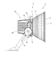
図1は、本実施の形態に係るLED照明器具1の全体像を示した図である。
LED照明器具1は、反射鏡ユニット5と、LED光源ユニット10とを備える。
反射鏡ユニット5は、反射鏡4と、反射鏡4の先端の照射開口3と、照射開口3に固定される前面ガラス(光透過部材)2とを備える。
前面ガラス2は照射開口3の周縁部に所謂かしめ結合されており、前面ガラス2の外周部と照射開口3の周縁部は防水された状態である。また、反射鏡ユニット5は、図5に示すように、反射鏡4の後端に開口6と、開口6の周囲に備えられる光源ユニット接続部(取付けフランジ)7と、反射鏡4の後端部に備えられるアーム取付け片8と、アーム取付け片8に取付けられたアーム9とを備える。
上記LED光源ユニット10は、反射鏡4の後端の開口6に、取付けフランジ7を介して防水状態で取付けられている。
Hereinafter, embodiments of the present invention will be described with reference to the drawings.
FIG. 1 is a diagram showing an overall image of the
The
The reflecting
The
The LED
図2、図3は、LED光源ユニット10を示す。
LED光源ユニット10は、ベースプレート18と、ベースプレート18に連結されたヒートシンク19と、ヒートシンク19を覆う樹脂製カバー20とを備える。ベースプレート18の中央部には、COB型LED17が配置されている。COB型LED17は、多数のLEDをLED基板31の上に密集配置して平面視略円形(四角形も有り得る)の面状の発光部31Aを形成したチップオンボード(Chip On Board:COB)構造の発光デバイスである。COB型LED17は、多数のLEDが密集配置されていることから大光量、及び高輝度なLED光源となる。本構成では、電源ボックス(不図示)が、LED光源ユニット10と別置である。したがって、電源値を変化させることで、複数の光学性能を包括可能なLED光源ユニット10を構成できる。
COB型LED17の上には、シリコンパッキン16と、絶縁シート15と、LED光源防水パッキン14と、が配置されている。
2 and 3 show the LED
The LED
On the
LED光源防水パッキン14と密着して、相フランジ13が配置され、相フランジ13は、反射鏡ユニット5の取付けフランジ7に接合される。相フランジ13には取っ手13aが取付けられており、この取っ手13aを持ってLED照明器具へのリニューアルの作業を容易に行うことができる。相フランジ13の上には、LED押え金具12と、LED光源反射鏡11と、が配置されている。
なお図4に示すように、LED光源反射鏡11の前面開口にアクリル板などの光透過性を有する保護カバー30を配置してもよい。
保護カバー30は、LED光源ユニット10を、例えば単体で使用する場合、LED光源の保護と安全性の観点から充電部保護のため設けられる。COB型LED17に直接手を触れさせないため、保護カバー30には手指が入らない大きさの通気孔29、29…を複数設ける構成としてもよい。この通気孔29、29…は充電部保護の効果と、保護カバー30を装着することによるLEDの温度上昇による光学性能(光出力)の低下を抑える効果を同時に奏する。また、通気孔29、29…は、図4に示すように、保護カバー30のカバー面に同心的に配置されている。この通気孔31、31…は円弧状の長孔で形成され、保護カバー30の中心から外に向けて円環状に等間隔で配置される。この配置により、カバー面に通気孔29、29…の有る箇所と、無い箇所からの透過光による照射面での照度ムラを抑える効果を合わせて奏する。
A
In addition, as shown in FIG. 4, you may arrange | position the
When the LED
ベースプレート18は、COB型LED17が直接的に取付けられる基板取付け部材であり、高熱伝導材である。例えば金属であるアルミニウムから形成されている。ベースプレート18は、図2に示すように、略円板状に形成され、その表面の中央にLED収容凹部40が設けられており、このLED収容凹部40に上記COB型LED17のLED基板31が収められ、その上面がシリコンパッキン16と絶縁シート15とにより覆われている。なお、COB型LED17からLED収容凹部40への伝熱を促進するために、両者の接触面に熱伝導グリス等を塗布し、或いは、熱伝導シートを介在させて両者間の熱抵抗を小さくしても良い。
The
ベースプレート18の表面には、LED収容凹部40を囲む環状のLED押え金具12がネジ止め固定され、このLED押え金具12にLED光源反射鏡11が固定される。このLED押え金具12は、ベースプレート18へのネジ止め固定に伴い、COB型LED17のLED基板31、シリコンパッキン16、絶縁シート15、LED光源防水パッキン14、及び相フランジ13を上から押さえ付けるように構成されている。これにより、LED押え金具12の固定によってCOB型LED17の固定も兼ねられることとなり、ベースプレート18へのCOB型LED17のネジ止め固定等が不要となる。
On the surface of the
LED光源反射鏡11は、回転放物体や回転楕円体などの回転体形状であり、その内面に所定の配光制御に応じて決定された回転放物反射面や回転楕円反射面が形成された凹面鏡である。このLED光源反射鏡11は、樹脂材を母材とし、その表面に反射材をコーティングすることで構成されており、金属材から形成する場合に比べて軽量化が図られている。また、このLED光源反射鏡11は、ねじ込み式で上記LED押え金具12に取付け固定される。具体的には、LED光源反射鏡11の基端部35Aの縁部には、LED押え金具12の溝に係合する鍔部33が設けられている。LED押え金具12には係合溝42Aが設けられ、係合溝42Aに上記鍔部33が入り込み、LED光源反射鏡11の回転に伴って鍔部33が係合溝42Aに脱落不能に係合する。
LED光源反射鏡11の固定時には、この係合溝42Aに鍔部33をねじ込むことで、別途に工具を用いることなくLED光源反射鏡11を固定できる。また、LED光源反射鏡11の鍔部33も樹脂材で形成されており、係合溝42Aと鍔部33の間にバネ力(弾性力)が働き、両者の結合力が高められている。
The LED light
When the LED light
このLED光源ユニット10では、ベースプレート18とLED押え金具12の間が、絶縁シート15により絶縁され、LED押え金具12と相フランジ13の間が、LED光源防水パッキン14により絶縁される。
したがって、ベースプレート18に取付けられたCOB型LED17と、相フランジ13の間は絶縁される。これによれば、図1に示すように、反射鏡ユニット5の取付けフランジ7と、LED光源ユニット10の相フランジ13とを接合する際に、COB型LED17と、反射鏡ユニット5の間は絶縁されており、COB型LED17のアース線の接続などが不要になる。
In this LED
Therefore, the
ヒートシンク19は、COB型LED17からベースプレート18に伝えられた熱を放熱する放熱機構である。具体的には、ヒートシンク19は、複数枚の放熱フィン48と、ベースプレート18に伝えられたCOB型LED17の熱を放熱フィン48に伝える複数本のヒートパイプ49とを備えている。
放熱フィン48は、略矩形状の板材であり、熱伝導性に優れ軽量な金属材であるアルミニウム板で形成されている。多数枚の放熱フィン48を上記ヒートパイプ49のそれぞれが貫通し、これらの放熱フィン48が互いに所定間隔をあけるように積層して一体に束ねられている。これら放熱フィン48は、支持金具(不図示)によって、ベースプレート18の裏面から垂直に延びるように配置される。支持金具(不図示)は、放熱フィン48とベースプレート18の裏面との間に所定の隙間を設けて支持し、この隙間を通じてベースプレート18の裏面と放熱フィン48を空気が流通可能となり、ベースプレート18の裏面の熱溜まりが抑制される。
本構成では、ヒートシンク19を覆って樹脂製カバー20が設けられている。この樹脂製カバー20には、ヒートシンク19に対し、垂直に多数の空気の流通孔が設けられている。
The
The radiating
In this configuration, a
図5は、LED照明器具1の分解斜視図である。
反射鏡ユニット5において、反射鏡4の後端開口6の周囲には、円環状の取付けフランジ7が配置されている。取付けフランジ7は内周部に周溝(不図示)を備え、この周溝(不図示)にはOリング51が配置されている。
また、取付けフランジ7は、外周部に周方向に3等分に配置された止め具52を備えている。3つの止め具52は同じ構造であり、反射鏡4の後端に固定された一対の耳片53と、一対の耳片53の間に、一端が回動自在に支持されたボルト54と、ボルト54の他端に螺合した蝶ナット55とを備えている。
LED光源ユニット10において、反射鏡ユニット5の取付けフランジ7に接合される相フランジ13は、図2に示すように、Oリング51に密着する密着面13bと、密着面13bの外周側で、止め具52と相対する係止片57とを備える。この係止片57には、取付けフランジ7に相フランジ13が接合されたとき、図1に示すように、上記ボルト54が係合自在な溝部57aが形成されている。
上述した構成の取付けフランジ7と、相フランジ13とを接合させ、止め具52と係止片57とを連結させることにより、反射鏡ユニット5に対し、LED光源ユニット10が、Oリング51の機能と共に防水の状態で結合される。
FIG. 5 is an exploded perspective view of the
In the reflecting
Moreover, the
In the LED
By connecting the mounting
なお本構成において、LED光源ユニット10は、LED光源反射鏡11により光の配光を制御する。したがって、LED照明器具1では、反射鏡ユニット5の反射鏡4は、単に防水構造を提供するだけであり、光の配光の制御には寄与しない。
またLED光源反射鏡11は必須のものではない。例えば、COB型LED17を使用したとして、LED光源反射鏡11の代わりに配光用のレンズを用いてもよい。
In this configuration, the LED
Further, the LED light
図6は、HID照明器具100の分解斜視図である。
HID照明器具100は、HIDランプユニット71と、上述した実施の形態の反射鏡ユニットと同じ構成を備えた反射鏡ユニット5と、を備えている。すなわち、この反射鏡ユニット5は、少なくとも、上述した構成の取付けフランジと共通の構造を有する取付けフランジ7を備えている。
HIDランプユニット71は、光源たるHIDランプ72と、このHIDランプ72やソケット(図示せず)等を収容する略筒状の光源筒73とを備え、この光源筒73の開口端73Aには、相フランジ113を備えている。
FIG. 6 is an exploded perspective view of the
The
The
上記相フランジ113は、HIDランプユニット71を反射鏡ユニット5に取り付けるために配置されている。
反射鏡ユニット5の取付けフランジ7は、上述したように、内周部に周溝(不図示)を備え、この周溝(不図示)にはOリング51が配置され、かつ、外周部には周方向に3等分に配置された止め具52を備えている。
3つの止め具52は同じ構造であり、反射鏡4の後端に固定された一対の耳片53と、一対の耳片53の間に、一端が回動自在に支持されたボルト54と、ボルト54の他端に螺合した蝶ナット55とを備えている。
The
As described above, the mounting
The three
HIDランプユニット71において、反射鏡ユニット5の取付けフランジ7に接合される相フランジ113は、Oリング51に密着する密着面(不図示)と、密着面(不図示)の外周側で、止め具52と相対する係止片157とを備える。この係止片157には、取付けフランジ7に相フランジ113が接合されたとき、上記ボルト54が係合自在な溝部157aが形成されている。
上述した構成の取付けフランジ7と、相フランジ113とを接合させ、止め具52と係止片157とを連結させることにより、反射鏡ユニット5に対し、HIDランプユニット71が、Oリング51の機能と共に防水の状態で結合される。
In the
By connecting the mounting
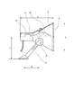
図7は、JIL 5004-2012 公共施設用照明器具(一般社団法人 日本照明工業会刊行)に規定されたHID照明器具100を示す。
公共施設用照明器具は、一般社団法人 日本照明工業会の公共施設用照明器具標準委員会が定める共通仕様であり、公共施設照明器具標準形名が同一ならば、メーカーを問わず同等の器具設計をされた器具となるため、器具を設置する施設に合わせた器具の選択をする際に有用となる。
ここに規定されたサイズのHID照明器具100の場合には、HIDランプユニット71の代わりにLED光源ユニット10を取付けたとき、反射鏡4の内側に籠る熱でCOB型LED17の性能が劣化せず、防水性も確保できることが判明している。
このHID照明器具100では、全長a、反射鏡4の先端の照射開口3の幅b、アーム9の下端からHIDランプ2のセンターまでの高さc、アーム9上端の回転中心とアーム9下端のボルト孔位置との距離dとする。
この実施の形態の適用は、全長aが、380〜470mmで、幅bが、350〜440mmで、高さcが、250〜360mmで、かつ、高さdが、180〜275mmにあるか、或いは、全長aが、490〜600mmで、幅bが、510〜590mmで、高さcが、290〜420mmで、かつ、距離dが、180〜325mmにある、HID照明器具100に、好適である。
FIG. 7 shows an
The lighting equipment for public facilities is a common specification established by the Japan Lighting Industry Association's Standard Committee for Public Lighting Equipment for Public Facilities. Therefore, it is useful when selecting a device suitable for the facility where the device is installed.
In the case of the
In this
The application of this embodiment is that the total length a is 380 to 470 mm, the width b is 350 to 440 mm, the height c is 250 to 360 mm, and the height d is 180 to 275 mm. Alternatively, it is suitable for the
本実施の形態では、LED照明器具1の反射鏡ユニット5に対し、LED光源ユニット10を取り付ける際には、取付けフランジ7と、相フランジ13とを接合させ、止め具52と係止片57とを連結させることにより、反射鏡ユニット5に対し、LED光源ユニット10を、Oリング51の機能と共に防水の状態で結合できる。
また、HID照明器具100の反射鏡ユニット5に対し、HIDランプユニット71を取り付ける際には、取付けフランジ7と、相フランジ113とを接合させ、止め具52と係止片157とを連結させることにより、反射鏡ユニット5に対し、HIDランプユニット71を、Oリング51の機能と共に防水の状態で結合できる。
In the present embodiment, when the LED
Further, when the
したがって、例えば、一つの大空間を多数のHID照明器具100を用いて照明する現場において、HID照明器具100の一つ、または二つにランプ切れがあったとき、全体の照明デザインを崩すことなく、ランプ切れのHIDランプユニット71のみを、LED光源ユニット10に順次、置き換えが可能となる。
HIDランプユニット71を、現場状況に応じ、順々に、LED光源ユニット10に置き換えていくことが可能となるため、経済的負担を減らしつつ、全体の照明デザインを維持しながら、省エネルギー化を達成できる。
Therefore, for example, in a site where a large space is illuminated with a large number of
Since it is possible to replace the
以上、一実施の形態に基づいて本発明を説明したが、本発明は、これに限定されるものではない。反射鏡ユニット5において、周方向に3等分に配置された止め具52を備える取付けフランジ7を説明したが、止め具の構成はこれに限定されない。例えば、パチン錠(スナップ・ファスナー式)などの止め具であってもよい。
As mentioned above, although this invention was demonstrated based on one Embodiment, this invention is not limited to this. In the reflecting
1 LED照明器具
2 前面ガラス(光透過部材)
4 反射鏡
5 反射鏡ユニット
7 取付けフランジ
10 LED光源ユニット
11、113 相フランジ
17 COB型LED
71 HIDランプユニット
72 HIDランプ
100 HID照明器具
1
4 Reflecting
71 HID
Claims (10)
Priority Applications (1)
| Application Number | Priority Date | Filing Date | Title |
|---|---|---|---|
| JP2015031653A JP5897744B2 (en) | 2015-02-20 | 2015-02-20 | Lighting apparatus and LED light source unit |
Applications Claiming Priority (1)
| Application Number | Priority Date | Filing Date | Title |
|---|---|---|---|
| JP2015031653A JP5897744B2 (en) | 2015-02-20 | 2015-02-20 | Lighting apparatus and LED light source unit |
Related Parent Applications (1)
| Application Number | Title | Priority Date | Filing Date |
|---|---|---|---|
| JP2014041030 Division | 2014-03-03 | 2014-03-03 |
Publications (3)
| Publication Number | Publication Date |
|---|---|
| JP2015167130A JP2015167130A (en) | 2015-09-24 |
| JP2015167130A5 JP2015167130A5 (en) | 2015-11-05 |
| JP5897744B2 true JP5897744B2 (en) | 2016-03-30 |
Family
ID=54257911
Family Applications (1)
| Application Number | Title | Priority Date | Filing Date |
|---|---|---|---|
| JP2015031653A Active JP5897744B2 (en) | 2015-02-20 | 2015-02-20 | Lighting apparatus and LED light source unit |
Country Status (1)
| Country | Link |
|---|---|
| JP (1) | JP5897744B2 (en) |
Family Cites Families (6)
| Publication number | Priority date | Publication date | Assignee | Title |
|---|---|---|---|---|
| US7985005B2 (en) * | 2006-05-30 | 2011-07-26 | Journée Lighting, Inc. | Lighting assembly and light module for same |
| CN101619822B (en) * | 2008-06-30 | 2012-12-19 | 鸿富锦精密工业(深圳)有限公司 | Lighting device |
| CH704544A1 (en) * | 2011-02-22 | 2012-08-31 | Regent Beleuchtungskoerper Ag | Lighting apparatus to heat spreader. |
| JP5901222B2 (en) * | 2011-10-24 | 2016-04-06 | 株式会社アイ・ライティング・システム | Light source unit |
| US9470391B2 (en) * | 2011-11-17 | 2016-10-18 | Osram Gmbh | LED light source module |
| JP2015111497A (en) * | 2012-03-30 | 2015-06-18 | パナソニック株式会社 | Lamp |
-
2015
- 2015-02-20 JP JP2015031653A patent/JP5897744B2/en active Active
Also Published As
| Publication number | Publication date |
|---|---|
| JP2015167130A (en) | 2015-09-24 |
Similar Documents
| Publication | Publication Date | Title |
|---|---|---|
| US9890943B2 (en) | Thermally dissipated lighting system | |
| US20140293612A1 (en) | Novel led wall lamp | |
| JP2014086159A (en) | Lighting device | |
| CA2904457C (en) | Led ring assembly | |
| JP6539859B2 (en) | Translucent member and lighting apparatus provided with the same | |
| JP2010198828A (en) | Lighting device | |
| JP5530746B2 (en) | Light emitting diode lamp | |
| JP6276930B2 (en) | lighting equipment | |
| JP5019042B2 (en) | Lighting device and lighting fixture | |
| JP6179760B2 (en) | lighting equipment | |
| JP6628480B2 (en) | lighting equipment | |
| JP5897744B2 (en) | Lighting apparatus and LED light source unit | |
| KR200463715Y1 (en) | Assembling structure of the illuminators for medical usage | |
| JP6433016B2 (en) | Large light LED floodlight | |
| JP6251081B2 (en) | Reflection unit and LED module | |
| JP6463918B2 (en) | Light source module, lighting fixture and emergency lighting fixture | |
| JP5991169B2 (en) | lighting equipment | |
| JP6518081B2 (en) | lighting equipment | |
| JP2018206548A (en) | Light fitting | |
| KR20190054595A (en) | LED lighting lamp of down-lighting type | |
| JP2011070946A (en) | Lighting device | |
| JP2018037342A (en) | lamp | |
| JP2016004602A (en) | Lighting device | |
| JP6287096B2 (en) | Lighting equipment and heat dissipation unit | |
| JP6558689B2 (en) | lighting equipment |
Legal Events
| Date | Code | Title | Description |
|---|---|---|---|
| A521 | Written amendment |
Free format text: JAPANESE INTERMEDIATE CODE: A523 Effective date: 20150916 |
|
| A621 | Written request for application examination |
Free format text: JAPANESE INTERMEDIATE CODE: A621 Effective date: 20150916 |
|
| A871 | Explanation of circumstances concerning accelerated examination |
Free format text: JAPANESE INTERMEDIATE CODE: A871 Effective date: 20150916 |
|
| A975 | Report on accelerated examination |
Free format text: JAPANESE INTERMEDIATE CODE: A971005 Effective date: 20151015 |
|
| A131 | Notification of reasons for refusal |
Free format text: JAPANESE INTERMEDIATE CODE: A131 Effective date: 20151027 |
|
| A521 | Written amendment |
Free format text: JAPANESE INTERMEDIATE CODE: A523 Effective date: 20151225 |
|
| TRDD | Decision of grant or rejection written | ||
| A01 | Written decision to grant a patent or to grant a registration (utility model) |
Free format text: JAPANESE INTERMEDIATE CODE: A01 Effective date: 20160209 |
|
| A61 | First payment of annual fees (during grant procedure) |
Free format text: JAPANESE INTERMEDIATE CODE: A61 Effective date: 20160302 |
|
| R150 | Certificate of patent or registration of utility model |
Ref document number: 5897744 Country of ref document: JP Free format text: JAPANESE INTERMEDIATE CODE: R150 |
|
| S531 | Written request for registration of change of domicile |
Free format text: JAPANESE INTERMEDIATE CODE: R313531 |
|
| R350 | Written notification of registration of transfer |
Free format text: JAPANESE INTERMEDIATE CODE: R350 |