JP5896879B2 - Power supply device and synchronous input device - Google Patents
Power supply device and synchronous input device Download PDFInfo
- Publication number
- JP5896879B2 JP5896879B2 JP2012238578A JP2012238578A JP5896879B2 JP 5896879 B2 JP5896879 B2 JP 5896879B2 JP 2012238578 A JP2012238578 A JP 2012238578A JP 2012238578 A JP2012238578 A JP 2012238578A JP 5896879 B2 JP5896879 B2 JP 5896879B2
- Authority
- JP
- Japan
- Prior art keywords
- amplitude
- power supply
- voltage
- supply device
- power system
- Prior art date
- Legal status (The legal status is an assumption and is not a legal conclusion. Google has not performed a legal analysis and makes no representation as to the accuracy of the status listed.)
- Active
Links
- 230000001360 synchronised effect Effects 0.000 title claims description 48
- 238000000034 method Methods 0.000 claims description 35
- 230000008569 process Effects 0.000 claims description 31
- 238000005259 measurement Methods 0.000 claims description 18
- 230000001960 triggered effect Effects 0.000 claims 1
- 238000004364 calculation method Methods 0.000 description 16
- 230000005540 biological transmission Effects 0.000 description 14
- 238000010248 power generation Methods 0.000 description 6
- 230000000737 periodic effect Effects 0.000 description 5
- 238000010586 diagram Methods 0.000 description 4
- 238000009825 accumulation Methods 0.000 description 3
- 238000006243 chemical reaction Methods 0.000 description 3
- 230000006870 function Effects 0.000 description 3
- 238000002347 injection Methods 0.000 description 3
- 239000007924 injection Substances 0.000 description 3
- 230000008859 change Effects 0.000 description 2
- 238000011084 recovery Methods 0.000 description 2
- 238000004088 simulation Methods 0.000 description 2
- 230000001934 delay Effects 0.000 description 1
- 230000003111 delayed effect Effects 0.000 description 1
- 238000001514 detection method Methods 0.000 description 1
- 230000000694 effects Effects 0.000 description 1
- 230000005611 electricity Effects 0.000 description 1
- 238000005516 engineering process Methods 0.000 description 1
- 230000003993 interaction Effects 0.000 description 1
- 230000007774 longterm Effects 0.000 description 1
- 230000004044 response Effects 0.000 description 1
- 230000035939 shock Effects 0.000 description 1
Images


Description
この発明は、電力系統と電気的に接続/遮断可能な電源装置と、上記電源装置用の同期投入装置に関する。 The present invention relates to a power supply apparatus that can be electrically connected / disconnected to / from an electric power system, and a synchronous input apparatus for the power supply apparatus.
容量の大小を問わず、電源装置(電源設備)を起動した状態で電力系統へ連系するには、電源設備が生成する電圧波形と、電力系統の電圧波形とを、同じ振幅・位相とした時点で両者を結ぶ遮断器を投入する、同期投入装置が必要とされる。両者の電圧の振幅もしくは位相が異なる状態で遮断器を投入する非同期投入では、遮断器投入と同時に不要な電流である横流が発生し、電源設備や電力系統の過負荷、系統擾乱を引き起こす。 Regardless of the capacity, to connect to the power system with the power supply (power supply equipment) activated, the voltage waveform generated by the power supply equipment and the voltage waveform of the power system have the same amplitude and phase. There is a need for a synchronous closing device that puts in a circuit breaker that connects the two at the time. Asynchronous closing in which the circuit breaker is turned on when the amplitude or phase of both voltages are different causes a cross current that is an unnecessary current at the same time as turning on the circuit breaker, leading to overloading of the power supply facility and power system and system disturbance.
そこで従来の同期投入装置では、同期投入したい電源装置側の電圧・振幅と、電力系統側の電圧振幅・位相とを同時に計測し、その電圧差・位相差が縮小される方向に電源装置に対して出力電圧の波形を変化させるように指令する。そして、電源装置は、その指令を受け、自身の出力電圧の波形を徐々に能動的に変化させながら、別途設けた同期投入装置によって、両電圧振幅・位相が合致した時点で遮断器を投入する。このような同期投入装置として、例えば特許文献1に開示された同期投入制御装置がある。 Therefore, in the conventional synchronous input device, the voltage / amplitude on the power supply side to be synchronized and the voltage amplitude / phase on the power system side are measured simultaneously, and the voltage difference / phase difference is reduced in the direction in which the voltage difference / phase difference is reduced. Command to change the waveform of the output voltage. In response to the command, the power supply device gradually and actively changes the waveform of its own output voltage, and turns on the circuit breaker when both voltage amplitudes and phases are matched by the separately provided synchronous closing device. . As such a synchronization input device, for example, there is a synchronization input control device disclosed in Patent Document 1.
従来の同期投入技術では、大容量ないし中容量の回転型発電設備の電源装置を同期投入対象としている。一般に中・大容量の回転型発電設備は、負荷を接続せず発電量がゼロとなる単独状態で起動し、同期投入による系統連系後に初めて発電を開始する。ところが中・大容量の発電設備は発電量がゼロである無負荷状態で長時間運転することができない。そこで従来の同期投入技術では、同期投入の高速化が重視され、目的とされていた。 In the conventional synchronous charging technique, the power supply device of a large-capacity to medium-capacity rotary power generation facility is targeted for synchronous charging. Generally, medium- and large-capacity rotary power generation facilities start up in a single state where the amount of power generation becomes zero without connecting a load, and power generation starts only after grid connection by synchronous input. However, medium- and large-capacity power generation facilities cannot be operated for a long time in a no-load state where the amount of power generation is zero. Therefore, in the conventional synchronous input technology, the high speed of synchronous input is emphasized and has been aimed.
一方、大規模災害などにより電力系統が数時間に及んで停電する長期停電時に、小容量電源設備や蓄電設備を用いた住宅などの小規模施設内の自立運転が注目されている。 On the other hand, self-sustained operation in small-scale facilities such as houses using small-capacity power supply facilities and power storage facilities is attracting attention during a long-term power outage in which the power system takes several hours due to a large-scale disaster.
ところが電力系統が復電した際、同施設(電源装置)を無停電のまま電力系統へ接続するためには、電源装置,電力系統間で同期投入が必要となる。しかし同期投入装置とそれに連動して出力電圧の波形を調整する電源装置は、装置構成が複雑化し高価である。そのため、小規模施設の電源装置の自立運転では、自立運転状態から一旦電源装置を停止させ、停電した状態で同電源装置を電力系統へ接続する停電切替えを行うのが一般的であった。 However, when the power system is restored, in order to connect the facility (power supply device) to the power system without an uninterruptible power supply, synchronization between the power supply device and the power system is required. However, the power supply apparatus that adjusts the waveform of the output voltage in conjunction with the synchronous input apparatus is complicated and expensive. Therefore, in the self-sustaining operation of the power supply device in a small-scale facility, it is common to temporarily stop the power supply device from the self-sustaining operation state, and to perform a power failure switching that connects the power supply device to the power system in a power failure state.
この発明は、上記のような問題点を解決するためになされたものであり、比較的簡単な装置構成で同期投入処理が可能な電源装置及びその電源装置用の同期投入装置を得ることを目的としている。 The present invention has been made to solve the above-described problems, and an object of the present invention is to obtain a power supply device capable of synchronous input processing with a relatively simple device configuration and a synchronous input device for the power supply device. It is said.
この発明に係る請求項1記載の本願発明である電源装置は、電力系統と電気的に接続可能な電源装置であって、前記電力系統と電気的に接続時に、前記電力系統から供給される交流電圧である電力系統電圧の波形に合わせて自身の交流電圧である連系出力電圧の波形を決定して該連系出力電圧を生成する連系運転を行う連系運転実行部と、前記電力系統と電気的に非接続時に、前記電力系統電圧とは独立した交流電圧である自立出力電圧の波形を決定して該自立出力電圧を生成する自立運転を実行する自立運転実行部とを備え、前記自立運転実行部は、前記自立運転時に、前記電力系統電圧の基準周波数Hsと近似範囲内で異なる自立周波数Hgとなる前記自立出力電圧の波形を決定する自立運転用波形決定部を有し、前記自立運転用波形決定部は、位相合致時間Th(=1/|Hg−Hs|)に対し短く設定された振幅変動周期Tv毎に振幅変動範囲内で振幅が変化するように前記自立出力電圧の波形を決定する。 The power supply device according to the first aspect of the present invention according to the present invention is a power supply device that can be electrically connected to an electric power system, and is an alternating current supplied from the electric power system when electrically connected to the electric power system. A grid operation execution unit that performs a grid operation for generating a grid output voltage by determining a waveform of a grid output voltage that is an AC voltage in accordance with a waveform of a power grid voltage that is a voltage; and the power grid A self-sustained operation execution unit for performing a self-sustained operation for determining a waveform of a self-sustained output voltage that is an AC voltage independent of the power system voltage and generating the self-sustained output voltage when electrically disconnected from the power system voltage, isolated operation execution unit, said during autonomous operation, have a self-sustained operation waveform determining section for determining a waveform of the self output voltage as a different autonomous frequency Hg within the approximate range as the reference frequency Hs of the power system voltage, the Waveform decision for autonomous operation Parts are phase matched time Th to determine the waveform of the self output voltage to vary the amplitude in the amplitude fluctuation range for each set shorter to amplitude variation period Tv that (= 1 / | | Hg- Hs).
請求項1記載の本願発明である電源装置は、基準周波数Hsと近似範囲内で異なる自立周波数Hgとなる自立出力電圧の波形を決定しており、位相合致周期Th=1/|Hg−Hs|内において、自立出力電圧の位相と電力系統電圧の位相が合致する瞬間が必ず生じさせることができる。 The power supply device according to the first aspect of the present invention determines the waveform of the self-sustained output voltage having a self-sustained frequency Hg that is different from the reference frequency Hs within the approximate range, and the phase matching period Th = 1 / | Hg−Hs | The moment when the phase of the self-sustained output voltage matches the phase of the power system voltage can always be generated.
すなわち、電力系統の復電時に電力系統を電源装置に電気的に接続するとともに、電源装置を自立運転から連系運転に移行させる同期投入処理が必要な際、電源装置の自立出力電圧の位相を、電力系統電圧の位相に合致するための能動的な制御を何ら必要とせずに、位相合致周期Th以内には必ず自立出力電圧の位相と電力系統電圧の位相とが合致する位相合致タイミングを発生させることができる。 In other words, when the power system is electrically connected to the power supply device at the time of power recovery, and the synchronous input processing for shifting the power supply device from the independent operation to the interconnection operation is necessary, the phase of the independent output voltage of the power supply device is changed. Without the need for any active control to match the phase of the power system voltage, the phase match timing that always matches the phase of the self-sustained output voltage and the phase of the power system voltage is generated within the phase matching period Th. Can be made.
その結果、上記位相合致タイミングに合わせて上記同期投入処理を実行することができるため、電源装置の能動的な位相制御の必要性を実質的になくすことができ、電源装置の簡略化を図ることができる。 As a result, since the synchronization process can be executed in accordance with the phase matching timing, the necessity of active phase control of the power supply device can be substantially eliminated, and the power supply device can be simplified. Can do.
<実施の形態1>
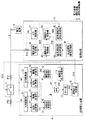
図1はこの発明の実施の形態1である電源装置を含む電源環境を示すブロック図である。
<Embodiment 1>
1 is a block diagram showing a power supply environment including a power supply apparatus according to Embodiment 1 of the present invention.
同図に示すように、電源環境は主として、電力系統1、構内系統2、連系用遮断器3、同期投入装置4、電源装置5及び電力負荷6から構成されている。電力系統1は電力会社などが保有し、構内系統2は電力需要家などが保有する系統であり、連系用遮断器3に近接した電力系統1及び構内系統2それぞれに電圧計PT1及びPT2が設けられる。
As shown in the figure, the power supply environment mainly includes a power system 1, a premises system 2, an
連系用遮断器3は電力系統1と構内系統2との間に設けられ、開放状態時に遮断器投入信号S18が投入を指示するとき、電力系統1と構内系統2と電気的に接続する投入状態となる。一方、連系用遮断器3は、手動操作等により開放状態に設定され、電力系統1と構内系統2とが電気的に分離される。電力負荷6は構内系統2に接続される種々の電力負荷である。
The
電源装置5は構内系統2に電気的に接続されており、電力系統1との電気的に接続時に実行される連系運転と、電力系統1との電気的に非接続時に実行される自立運転が可能である。
The
連系運転とは、電力系統1から供給される交流電圧である電力系統電圧の波形に合わせて自身の交流電圧である連系出力電圧の波形を決定して該連系出力電圧を生成する処理であり、自立運転とは、電力系統電圧とは独立した交流電圧である自立出力電圧の波形を決定して該自立出力電圧を生成する処理である。 The interconnected operation is a process of determining the waveform of the interconnected output voltage that is the AC voltage of the power system in accordance with the waveform of the power system voltage that is the AC voltage supplied from the power system 1, and generating the interconnected output voltage. The self-sustained operation is a process of generating a self-sustained output voltage by determining a waveform of the self-sustained output voltage that is an AC voltage independent of the power system voltage.
同期投入装置4は電力系統1の復電後、同期投入タイミングを検知し、開放状態の連系用遮断器3によって電気的に分離された状態の電力系統1と構内系統2とを再び、電気的に接続すべく、投入を指示する遮断器投入信号S18を連系用遮断器3に出力する等の同期投入処理を実行する。
The synchronization input device 4 detects the synchronization input timing after the power supply of the power system 1 is restored, and again connects the power system 1 and the on-site system 2 in the state of being electrically separated by the
電源装置5は、連系用遮断器3の投入状態時において、電力系統1により充電されている平常時は、連系運転を行い、電力負荷6へは電力系統1と電源装置5の両方から電力が供給される。
The
電力系統1が事故などで停電した場合には、連系用遮断器3は開放状態とされ、構内系統2に接続する電源装置5だけで電力負荷6へ電力を供給する自立運転を行う。なお、この自立運転時の構内系統2を自立運転系統と呼ぶ。自立運転時には、電源装置5は、自身で基準周波数と基準電圧に近い電圧波形を生成する。
When a power failure occurs in the power system 1 due to an accident or the like, the
(同期投入装置4)
まず、同期投入装置4の構成要素、並びに処理フローについて説明する。同期投入装置4は、電力系統1の復電後に、電力系統1と構内系統2とを最適な同期投入タイミングで電気的に接続する同期投入処理を行う装置である。
(Synchronous feeding device 4)
First, components of the synchronization input device 4 and a processing flow will be described. The synchronization input device 4 is a device that performs a synchronization input process for electrically connecting the power system 1 and the local system 2 at an optimal synchronization input timing after the power system 1 is restored.
電圧計PT1より測定された測定電圧(電力系統電圧)V1はA/D変換部11でA/D変換された後、デジタルデータとして位相計算部12及び振幅計算部13に付与される。そして、位相計算部12により算出位相P1(第1計測位相)が得られ、振幅計算部13より算出振幅A1(第1計測振幅)が得られる。
The measured voltage (power system voltage) V1 measured by the voltmeter PT1 is A / D converted by the A /
電圧計PT2より測定された測定電圧(構内系統電圧)V2はA/D変換部21でA/D変換された後、デジタルデータとして位相計算部22及び振幅計算部23に付与される。そして、位相計算部22により算出位相P2(第2計測位相)が得られ、位相計算部23より算出振幅A2(第2計測振幅)が得られる。
The measured voltage (in-house system voltage) V2 measured by the voltmeter PT2 is A / D converted by the A /
位相差判定部14は算出位相P1,P2を比較して、両者の位相差が同期投入処理が実行可能な位相差許容値内(例えば、±5°以内)である場合に“H”の位相判定結果JPを出力し、そうでない場合は“L”の位相判定結果JPを出力する。
The phase
振幅差判定部15は算出振幅A1,A2を比較して、両者の振幅差が同期投入処理が実行可能な振幅差許容値内(例えば、定格電圧比で±0.1%以内)である場合に“H”の振幅判定結果JAを出力し、そうでない場合は“L”の振幅判定結果JAを出力する。
The amplitude
論理積回路16は位相判定結果JP及び振幅判定結果JAの論理積を総合判定信号S16としてタイマー部17及び遮断器投入送信部18に出力する。
The
タイマー部17は総合判定信号S16を遅延時間ΔT遅延させて運転モード送信部19に出力する。
The
遮断器投入送信部18は“H”(良)の総合判定信号S16の入力を同期投入タイミングとして検知すると、この入力をトリガとして、「投入」を指示する遮断器投入信号S18を出力する。一方、遮断器投入送信部18は“L”の総合判定信号S16の入力時は何もしない。
When the circuit breaker
運転モード送信部19は、タイマー部17を経て得られる“H”の総合判定信号S16の入力をトリガとして、運転モードを自立運転から「連系運転」を指示する運転モード指示信号S19を出力する。一方、運転モード送信部19は“L”の総合判定信号S16の入力時は何もしない。
The operation
上述した位相差判定部14、振幅差判定部15、論理積回路16、タイマー部17、遮断器投入送信部18及び運転モード送信部19を主要構成として、上記同期投入タイミング検知をトリガとして、「投入」を指示する遮断器投入信号S18の出力及び「連系運転」を指示する運転モード指示信号S19を出力する同期投入処理を実行する同期投入実行部が構成される。
The above-described phase
このような構成において、同期投入装置4は、定周期(例えば、電気角30度周期:周波数50Hz系統では1.67ミリ秒、60Hz系統では1.39ミリ秒)で同期投入用定期処理を行う。 In such a configuration, the synchronization input device 4 performs a periodic process for synchronization input at a constant cycle (for example, an electrical angle of 30 degrees cycle: 1.67 milliseconds for a frequency of 50 Hz system and 1.39 milliseconds for a 60 Hz system). .
図2は同期投入装置4による同期投入用定期処理の処理手順を示すフローチャートである。 FIG. 2 is a flowchart showing the processing procedure of the periodic processing for synchronous input by the synchronous input device 4.
同図を参照して、ステップST1において、電源装置5が自立運転の実行中であるか否かを確認し、自立運転中であればステップST2以降の処理に進み、自立運転中で無く連系運転中であれば処理を終了する。したがって、連系用遮断器3が投入されている連系運転時には、同期投入装置4はその機能を実質的に停止している。
Referring to the figure, in step ST1, it is confirmed whether or not the
電力系統1が停電し、連系用遮断器3が手動操作などにより開放状態に設定され、電源装置5が手動操作等により自立運転モードに設定され自立運転が成立した時点で、ステップST1がYESとなり、同期投入装置4はステップST2以降を実行することにより実質的な動作を起動する。なお、ステップST1の自立運転時か否かの処理は、ユーザが手動で実行してもよいし、連系用遮断器3の開放/投入状態や電源装置5の運転モードを取り込んで同期投入装置4の(内部のCPU(図示せず)等による)制御下で自動判定する処理で実行しても良い。なお、以下に説明するステップST2以降の処理は、同期投入装置4の制御下で自動的に行われる。
Step ST1 is YES when the power system 1 is interrupted, the
ステップST2において、電圧計PT1及びPT2から得られる測定電圧V1及びV2がA/D変換部11及び12でそれぞれA/D変換された後、位相計算部12,振幅計算部13及び位相計算部22,振幅計算部23に付与される。すなわち、これらの計算部12,13及び22,23が、電圧の瞬時波形を計算処理可能なデジタルデータとして測定電圧V1及びV2は取り込まれる。
In step ST2, the measurement voltages V1 and V2 obtained from the voltmeters PT1 and PT2 are A / D converted by the A /
ステップST3において、ステップST2で取り込んだ電圧波形から測定電圧V1及びV2それぞれの位相・振幅を計算する。 In step ST3, the phases and amplitudes of the measurement voltages V1 and V2 are calculated from the voltage waveform acquired in step ST2.
位相計算部12は測定電圧(電力系統電圧)V1をA/D変換部11を介して取り込んだ電圧瞬時波形から電圧波形の位相を算出して算出位相P1を得る。また、振幅計算部13は、上記電圧瞬時波形から電圧波形の振幅を算出して算出振幅A1を得る。
The
位相計算部22は測定電圧(自立出力電圧)V2をA/D変換部21を介して取り込んだ電圧瞬時波形から電圧波形の位相を算出して算出位相P2を得る。また、振幅計算部23は、上記電圧瞬時波形から電圧波形の振幅を算出して算出振幅A2を得る。
The
なお、位相、及び振幅の算出方法は、様々な方式が実用化されているが、例えば離散フーリエ変換などの算出方法を求めれば良い。 Various methods for calculating the phase and amplitude have been put into practical use. For example, a calculation method such as discrete Fourier transform may be obtained.
その後、ステップST4において、位相差判定部14及び振幅差判定部15によって、位相差(|P1−P2|)及び振幅差(|A1−A2|)が求められる。
Thereafter, in step ST4, the phase
さらに、続くステップST5において、位相差が同期投入処理が実行可能な位相差許容値より小さく、かつ、振幅差が同期投入処理が実行可能な振幅差許容値より小さいという総合判定条件を満足するか否かが確認され、満足する場合(YES)はステップST6に移行し、満足しない場合(NO)は同期投入タイミングでは無いと判断し、処理を終了する。以下、ステップST5の具体的処理内容について説明する。 Furthermore, in the following step ST5, whether the comprehensive judgment condition that the phase difference is smaller than the allowable phase difference that can be executed by the synchronization application process and that the amplitude difference is less than the allowable amplitude difference that can be executed by the synchronization application process is satisfied. If satisfied or not (YES), the process proceeds to step ST6. If not satisfied (NO), it is determined that it is not the synchronization input timing, and the process ends. Hereinafter, the specific processing content of step ST5 is demonstrated.
位相差判定部14は上記位相差が上記位相差許容値より小さければ“H”の位相判定結果JPを出力し、そうでなければ“L”の位相判定結果JPを出力する。
The phase
振幅差判定部15は上記振幅差が上記振幅差許容値より小さければ“H”の振幅判定結果JAを出力し、そうでなければ“L”の振幅判定結果JAを出力する。
The amplitude
論理積回路16は位相判定結果JP及び振幅判定結果JAの論理積を求めることにより、位相判定結果JP及び振幅判定結果JAが共に“H”のとき、“H”(真:総合判定条件を満足した)の総合判定信号S16を出力し、それ以外のとき“L”の総合判定信号S16を出力する。
The
したがって、総合判定信号S16が“H”のとき、上記総合判定条件を満足する同期投入タイミングを指示することになる。 Therefore, when the comprehensive determination signal S16 is "H", a synchronization input timing that satisfies the comprehensive determination condition is instructed.
ステップST5でYESの場合に実行されるステップST6において、遮断器投入送信部18は“H”の総合判定信号S16の入力を同期投入タイミングとして検知し、“H”の総合判定信号S16の入力をトリガとして、「投入」を指示する遮断器投入信号S18を連系用遮断器3に付与する。
In step ST6, which is executed in the case of YES in step ST5, the circuit breaker
続くステップST7において、タイマー部17は総合判定信号S16を遅延時間ΔT遅らせて次段の運転モード送信部19に伝達する遅延時間待機処理(タイマー処理)を実行する。なお、遅延時間ΔTは、例えば、連系用遮断器3が「投入」を指示する遮断器投入信号S18を受けて、確実に投入状態となっていると想定される時間(例えば0.1秒)に設定される。したがって、連系用遮断器3が投入状態になる前に自立運転から連系運転に切り替えられて停電状態となる現象を確実に回避することができる。
In subsequent step ST7, the
その後、ステップST8において、運転モード送信部19は、“H”の総合判定信号S16の入力をトリガとして、電源装置5へ運転モードを自立運転から連系運転に切り替えるべく、「連系運転」を指示する運転モード指示信号S19を電源装置5の運転モード受信部32に出力する。
Thereafter, in step ST8, the operation
このように、同期投入装置4は、同期投入用定期処理を定期的に実行することにより、総合判定信号S16が“H”となる同期投入タイミングを検知し、このタイミングをトリガとして「投入」を指示する遮断器投入信号S18の出力し、「連系運転」を指示する運転モード指示信号S19の出力する同期投入処理を実行する。 As described above, the synchronization input device 4 periodically detects the synchronization input timing at which the comprehensive determination signal S16 becomes “H” by periodically executing the synchronization input periodic processing, and performs “input” using this timing as a trigger. The circuit breaker closing signal S18 to be instructed is output, and the synchronous closing process to be output of the operation mode instruction signal S19 to instruct “interconnection operation” is executed.
同期投入装置4は、算出位相P1,P2の位相差が位相合致許容範囲内にあり、かつ、算出振幅A1,A2の振幅差が振幅合致許容範囲内になった同期投入タイミングを検知し、このタイミングをトリガとして、上述した遮断器投入信号S18及び運転モード指示信号S19を出力する機能を有するだけで、複雑な演算処理を実行する機能を不要にして、同期投入処理を正常に行うことができる効果を奏する。 The synchronization input device 4 detects a synchronization input timing when the phase difference between the calculated phases P1 and P2 is within the phase matching allowable range and the amplitude difference between the calculated amplitudes A1 and A2 is within the amplitude matching allowable range. Only having the function of outputting the above-described circuit breaker closing signal S18 and operation mode instruction signal S19 with the timing as a trigger, the function of executing complicated arithmetic processing is unnecessary, and the synchronous closing process can be performed normally. There is an effect.
(電源装置5)
次に、実施の形態1の電源装置5の各構成要素について説明する。自立運転条件記録部36は、電力系統1側の基準周波数Hs(Hz)より微小に高い(もしくは低い)自立運転時の自立周波数Hg(Hz)を記録する。このように、自立周波数Hgは近似範囲内において基準周波数Hsと異なる値に設定される。
(Power supply 5)
Next, each component of the
なお、近似範囲としては、例えば、電力系統電圧と自立出力電圧とが数百秒で1サイクルずれる程度の範囲が考えられる。 As an approximate range, for example, a range in which the power system voltage and the self-sustained output voltage are shifted by one cycle in several hundred seconds is conceivable.
さらに、自立運転条件記録部36は、上述した自立周波数Hgに加え、以下の式(1)によって求められる位相合致周期Th(秒)よりも十分に短い電圧の振幅変動周期Tv(秒)と、自立出力電圧の振幅変動範囲である最大振幅Vtと最小振幅Vbとの4情報を予め記録している。これらの4情報(Hg,Tv,Vt,Vb)は、ユーザが設定するものとする。
Furthermore, in addition to the above-mentioned self-sustained frequency Hg, the self-sustained operation
Th=1/|Hg−Hs|…(1)
例えば、振幅変動範囲(最大振幅Vt,最小振幅Vb)は、予め定められた電力系統電圧の運用基準範囲に基づきユーザが設定して、自立運転条件記録部36に記録させる。
Th = 1 / | Hg-Hs | (1)
For example, the amplitude fluctuation range (maximum amplitude Vt, minimum amplitude Vb) is set by the user based on a predetermined operation reference range of the power system voltage, and is recorded in the independent operation
また、振幅変動周期Tvは後述する時間差条件を満足するレベルで位相合致周期Thより十分小さく設定される。振幅変動周期Tvは例えば位相合致周期Thの1/10以下に設定される。 The amplitude variation period Tv is set to be sufficiently smaller than the phase matching period Th at a level satisfying a time difference condition described later. The amplitude variation period Tv is set to, for example, 1/10 or less of the phase matching period Th.
自立運転用波形決定部34は、自立運転条件記録部36にて記録された自立周波数Hgと内部時間とから生成すべき自立運転時の自立出力電圧の波形の位相を決定するとともに、振幅変動周期Tvと最大振幅Vt、最大振幅Vtと内部時間とから、生成すべき自立出力電圧の波形の振幅を決定する。
The independent operation
図3は、電源装置5の自立運転時における構内系統電圧波形例を示すグラフである。同図に示す構内系統電圧波形L2、すなわち自立出力電圧は、基準周波数Hsを東日本の50(Hz)に対し、自立周波数Hgを50.002778(=50+1/360)(Hz)、振幅変動周期Tvを0.2(s)、最大振幅Vtを300(V)、最小振幅Vbを200(V)とした場合の電圧波形例である。
FIG. 3 is a graph showing an example of a local system voltage waveform during the self-sustaining operation of the
同図に示すように、自立運転時における構内系統電圧波形L2は1000/(50.002778)=19.999 (ms)周期の波形となり、振幅は200(ms)の振幅変動周期で200(V)と300(V)間で変化している。 As shown in the figure, the on-site system voltage waveform L2 during the self-sustaining operation is a waveform of 1000 / (50.002778) = 19.999 (ms) period, and the amplitude is 200 (V) and 300 (300 (ms) with an amplitude fluctuation period. V) is changing between.
このように、自立運転用波形決定部34は自立周波数Hg、振幅変動周期Tv、最大振幅Vt及び最小振幅Vbに基づき、自立運転時における自立出力電圧の波形を決定し、この電圧波形を規定した自立運転用波形データD34を運転モード切替部33に出力する。
As described above, the independent operation
なお、振幅変動周期Tv、最大振幅Vt、及び最小振幅Vbについては、説明の都合上変化が分かりやすいように、極端な数値を設定しているが、実際の運用では、振幅変動周期Tvは10(秒)、構内系統2を小容量の電源装置5が連系する200Vを基準系統とすると、最大振幅Vtは210×√2(V)、最小振幅Vbは190×√2(V)が妥当である(√2倍は実効値から瞬時値振幅への換算係数)。
For the amplitude fluctuation period Tv, the maximum amplitude Vt, and the minimum amplitude Vb, extreme numerical values are set so that the change can be easily understood for convenience of explanation. However, in actual operation, the amplitude fluctuation period Tv is 10 (Seconds) If 200V with the small-capacity
連系運転用波形決定部35は、電源装置5が構内系統2に電気的に接続する箇所に設けられた電圧計PT3からA/D変換部31を通して得られるデジタルの電圧波形の位相・振幅に合わせて、電源装置5が生成する連系運転時における連系出力電圧の電圧波形の位相・振幅からなる電圧波形を決定して、この電圧波形を規定した連系運転用波形データD35を運転モード切替部33に出力する。
The grid operation
運転モード受信部32は、同期投入装置4の運転モード送信部19より受信される運転モード指示信号S19の指示内容を運転モード切替部33に伝達する。なお、自立運転から連系運転への切替は、同期投入装置4からの指令(運転モード指示信号S19)で実施するが、連系運転から自立運転への切替えは、手動操作などで行う。
The operation
運転モード切替部33は、自立運転用波形データD34及び連系運転用波形データD35を受け、自立運転設定時には自立運転用波形データD34を選択波形データD33として電圧波形生成部30に出力し、連系運転設定時には、連系運転用波形データD35を選択波形データD33として電圧波形生成部30に出力する。
The operation
運転モード切替部33は、自立運転設定時において、運転モード受信部32を介して、「連系運転」への切替を指示する運転モード指示信号S19を受信すると、設定内容を連系運転に切り替える。すなわち、運転モード切替部33は自立運転用波形データD34に替えて、連系運転用波形データD35を選択波形データD33として出力する。
When the operation
電圧波形生成部30では、選択波形データD33で規定された電圧波形の位相・振幅に従い、実際の出力電圧の電圧波形を生成する。すなわち、自立運転時には、自立運転用波形データD34に基づく自立出力電圧の波形を生成し、連系運転時には、連系運転用波形データD35に基づく連系出力電圧の波形を生成する。
The
このように、連系運転用波形決定部35、運転モード切替部33及び電圧波形生成部30を主要構成として連系運転実行部が構成され、自立運転条件記録部36、自立運転用波形決定部34、運転モード切替部33及び電圧波形生成部30を主要構成として自立運転実行部が構成される。
As described above, the interconnected operation execution unit is configured with the interconnected operation
なお、電源装置5の電圧波形生成部30は、出力電圧を選択波形データD33で規定された周波数や振幅で制御可能な電力供給部であればよく、発電機の他、コージェネレーションシステムや蓄電池システムなどであっても良い。
The voltage
以下、電源装置5の特徴部分について詳述する。前述したのと同様、一例として、電力系統1の基準周波数Hsを50(Hz)、構内系統2の基準電圧を200(V)とし、自立周波数Hgを50.002778(Hz)、振幅変動周期Tvを10(s)、最大振幅Vtを210×√2(V)、最小振幅Vbを190×√2(V)とする波形条件を設定した場合を考える。この場合、以下の式(2)より、位相合致周期Thが求められる。
Hereinafter, the characteristic part of the
Th=1/|Hg−Hs|=1/0.002778=360(秒)…(2)
式(2)に示すように、360(秒)に一度の周期で、電力系統1側の電力系統電圧の波形の位相と、構内系統2側の自立出力電圧の電圧波形の位相が自ずと合致する。
Th = 1 / | Hg-Hs | = 1 / 0.002778 = 360 (seconds) (2)
As shown in equation (2), the phase of the power system voltage waveform on the power system 1 side and the phase of the voltage waveform of the self-sustained output voltage on the local system 2 side naturally match once every 360 (seconds). .
また、この前後10秒(=振幅変動周期Tv)程度の間で波形は500サイクル存在し、その間に自立出力電圧の電圧波形の振幅は190×√2(V)〜210×√2(V)、即ち実効値ベースでは190(V)〜210(V)間で変動する。 In addition, there are 500 cycles of the waveform for about 10 seconds before and after this (= amplitude fluctuation period Tv), and the amplitude of the voltage waveform of the self-sustained output voltage is 190 × √2 (V) to 210 × √2 (V) during that period. That is, on an effective value basis, it varies between 190 (V) and 210 (V).
電力系統電圧が実効値ベースで運用基準内である190〜210(V)に存在している限り、上記500サイクルの中のいずれかで、電力系統電圧の波形の位相・振幅が、電源装置5が生成する自立出力電圧の電圧波形の位相・振幅と合致するタイミングが必ず自然に発生する。
As long as the power system voltage exists within 190 to 210 (V) within the operation standard on an effective value basis, the phase / amplitude of the waveform of the power system voltage is determined by the
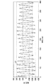
図4は、上記波形条件設定時での、電力系統電圧の電圧波形である電力系統電圧波形L1と、電源装置5の自立運転時における構内系統電圧波形L2とのシミュレーション結果を示すグラフである。
FIG. 4 is a graph showing a simulation result of the power system voltage waveform L1 that is the voltage waveform of the power system voltage when the waveform condition is set and the local system voltage waveform L2 when the
同図(a) に示すように、時間が0ms時点では、構内系統電圧波形L2が電力系統電圧波形L1より若干位相が進み、振幅も大き目となっている。しかし、同図(b) に示すように、時間が29,800ms時点では、電力系統電圧波形L1及び構内系統電圧波形L2の位相・振幅が共に合致している。 As shown in FIG. 5A, when the time is 0 ms, the local system voltage waveform L2 is slightly more advanced in phase than the power system voltage waveform L1, and the amplitude is also large. However, as shown in FIG. 5B, at the time of 29,800 ms, both the phase and amplitude of the power system voltage waveform L1 and the on-site system voltage waveform L2 match.
したがって、同期投入装置4は、上述したように、総合判定信号S16が“H”となる同期投入タイミングをトリガとして、「投入」を指示する遮断器投入信号S18を連系用遮断器3に出力するとともに、その遅延時間ΔT後に「連系運転」を指示する運転モード指示信号S19を電源装置5の運転モード受信部32に出力する同期投入処理が実行できる。その結果、同期投入装置4による同期投入処理により、最適なタイミングで連系用遮断器3を投入状態に設定し、かつ、電源装置5を自立運転から連系運転へスムーズに移行することが可能となる。
Therefore, as described above, the synchronization closing device 4 outputs the circuit breaker closing signal S18 instructing “turning on” to the
このように、同期投入装置4は、電力系統電圧の測定電圧V1と構内系統電圧(=自立出力電圧)の測定電圧V2との位相差及び振幅差が共に許容範囲であるか否かに基づき、同期投入装置4の投入制御処理、及び電源装置5を自立運転から連系運転に変更させる運転制御処理からなる同期投入処理を行うことができる。
As described above, the synchronization input device 4 is based on whether the phase difference and the amplitude difference between the measurement voltage V1 of the power system voltage and the measurement voltage V2 of the local system voltage (= independent output voltage) are both within the allowable range. It is possible to perform a synchronous charging process including a charging control process of the synchronous charging apparatus 4 and an operation control process for changing the
上述したように、実施の形態1の電源装置5は、自立周波数Hgを近似範囲内で基準周波数Hsと異なる周波数に設定しているため、位相合致周期Th秒の間には、自立出力電圧の位相と電力系統電圧の位相が合致する瞬間が必ず生じる。
As described above, the
すなわち、電力系統1の復電時に電力系統1を電源装置5に電気的に接続するとともに、電源装置5を自立運転から連系運転へと移行する同期投入処理が必要な際、電源装置5の自立出力電圧の位相を、電力系統電圧の位相に合致するための能動的な位相制御を必要とせずに、位相合致周期Th以内には必ず自立出力電圧の位相と電力系統電圧の位相とが合致する位相合致タイミングを発生させることができる。なお、位相合致タイミングは振幅計算部13が出力する位相判定結果JPが“H”となるタイミングを意味する。
That is, when the power system 1 is electrically connected to the
さらに、電力系統電圧の電圧変動を考慮した振幅変動範囲内で自立出力電圧の振幅を変動させた振幅変動周期の間に、自立出力電圧の振幅と電力系統電圧の振幅とが合致する瞬間が必ず生じる。 In addition, during the amplitude fluctuation period in which the amplitude of the self-sustained output voltage is varied within the amplitude fluctuation range that takes into account the voltage fluctuation of the power system voltage, there is always a moment when the amplitude of the self-sustained output voltage matches the amplitude of the power system voltage. Arise.
すなわち、電源装置5の自立出力電圧の振幅を、電力系統電圧の振幅に合致するように、能動的に制御することなく、時間Tv以内には必ず自立出力電圧の振幅と電力系統電圧の振幅とが合致する。
That is, the amplitude of the independent output voltage and the amplitude of the power system voltage are always within the time Tv without actively controlling the amplitude of the independent output voltage of the
この際、振幅変動周期Tvを位相合致周期Thに比べて十分短くしておけば、自立出力電圧の位相と電力系統電圧の位相とが合致した位相合致タイミングから十分短い時間Tv内に、自立出力電圧の位相及び振幅と電力系統電圧の位相及び振幅とが共に許容範囲内で合致して、総合判定信号S16が“H”となる同期投入タイミングが発生する。この際、位相差が少しズレる可能性があるが、振幅変動周期Tvは十分短いため、位相差は位相差許容値内に収まる。 At this time, if the amplitude fluctuation period Tv is made sufficiently shorter than the phase matching period Th, the self-sustained output is performed within a sufficiently short time Tv from the phase matching timing at which the phase of the self-sustained output voltage matches the phase of the power system voltage. The phase and amplitude of the voltage and the phase and amplitude of the power system voltage both match within an allowable range, and a synchronization input timing at which the overall determination signal S16 becomes “H” occurs. At this time, there is a possibility that the phase difference is slightly shifted, but since the amplitude variation period Tv is sufficiently short, the phase difference is within the phase difference allowable value.
その結果、同期投入装置4は同期投入タイミングに合わせて上記同期投入処理を実行することができるため、電源装置5の能動的な位相制御及び振幅制御の必要性を実質的になくすことができ、電源装置5の装置構成の簡略化(小型化)を図ることができる。
As a result, since the synchronization input device 4 can execute the synchronization input processing in synchronization with the synchronization input timing, the necessity of active phase control and amplitude control of the
特に、電力系統電圧の変動が振幅差許容値内に収まる場合等、電力系統電圧の振幅変動を考慮する必要が無い場合、上記位相合致タイミングと上記同期投入タイミングとは実質同一になるため、上記位相合致タイミングに合わせて上記同期投入処理を実行することが可能となる。この場合、電源装置5の能動的な位相制御の必要性を実質的になくすことができるため、電源装置5の装置構成の簡略化を図ることができる。
In particular, when there is no need to consider the amplitude fluctuation of the power system voltage, such as when the fluctuation of the power system voltage falls within the allowable amplitude difference, the phase match timing and the synchronization input timing are substantially the same. It is possible to execute the synchronous input process in accordance with the phase matching timing. In this case, since the necessity of active phase control of the
自立運転条件記録部36は、振幅変動範囲を予め定められた電力系統電圧の運用基準範囲に基づき決定することにより、自立出力電圧の位相及び振幅と電力系統電圧の位相及び振幅とが精度よく合致するタイミングを必ず設けることができる。
The autonomous operation
<実施の形態2>
図5は本発明の実施の形態2である電源装置を含む電源環境の構成を示すブロック図である。
<Embodiment 2>
FIG. 5 is a block diagram showing a configuration of a power supply environment including the power supply device according to the second embodiment of the present invention.
同図に示すように、同期投入装置4Bは同期投入装置4に比べ、振幅データベース25及び振幅範囲計算部26が追加された点、電源装置5Bは電源装置5に比べ、自立運転条件記録部36を自立運転条件記録部36Bに置き換えた点が異なる。他の構成は、図2で示した電源装置と同じであるため、適宜、同一符号を付して説明を省略する。
As shown in the figure, the
振幅データベース25は、振幅計算部13から算出振幅A1を入力し、入力された算出振幅A1を蓄積期間(例えば過去1年間分)分、逐次記憶する。
The
振幅範囲計算部26は、周期的(例えば1日周期)で起動し、振幅データベース25に蓄えられた蓄積期間における電力系統電圧の電圧波形の振幅値の中から、最大振幅値と最小振幅値を算出し、その算出結果を振幅範囲データD26として、電源装置5Bの自立運転条件記録部36Bに出力する。
The
最大振幅値、最小振幅値の算出には、上記蓄積期間内に単純に電力系統電圧の振幅の最大値、最小値を選択しても良いし、統計処理によって、平均値と標準偏差σを算出し、平均値+3σ(もしくは平均値+2σ)を最大振幅値、平均値−3σ(もしくは平均値−2σ)を最小振幅値としても良い。 To calculate the maximum and minimum amplitude values, you can simply select the maximum and minimum amplitudes of the power system voltage within the above accumulation period, or calculate the average value and standard deviation σ by statistical processing. The average value + 3σ (or average value + 2σ) may be the maximum amplitude value, and the average value −3σ (or average value −2σ) may be the minimum amplitude value.
電源装置5Bの自立運転条件記録部36Bは振幅範囲データD26に従い、最大振幅Vt及び最小振幅Vbを記録する。
The self-sustaining operation
電源装置5は、外部より得られる電力系統電圧の過去の変動実績に基づき決定することにより、電力系統1の実際の使用環境に適合させることができ、自立出力電圧の位相及び振幅と電力系統電圧の位相及び振幅とが精度よく合致するタイミングを必ず設けることができる。
The
<振幅変動周期Tvの時間差条件及び自立周波数Hgの近似範囲について>
振幅変動周期Tv及び自立周波数Hgと基準周波数Hsとの間の近似範囲は、
(a) 電力系統1側における位相差・振幅差の許容範囲と、
(b) 論理積回路16の総合判定信号S16が“H”となる同期投入タイミングから、実際に連系用遮断器3の同期投入・電源装置5の運転モード切替が完了するまでの時間差とに依存して変化する。
<About the time difference condition of the amplitude fluctuation period Tv and the approximate range of the independent frequency Hg>
The approximate range between the amplitude fluctuation period Tv and the self-supporting frequency Hg and the reference frequency Hs is:
(a) The allowable range of phase difference / amplitude difference on the power system 1 side,
(b) The time difference from the synchronous turn-on timing at which the overall judgment signal S16 of the
上記項目(a) については、一般的に、位相差15度以内、振幅差4%以内が電力系統1側の許容範囲の目安とされている。勿論、位相差及び振幅差が共に小さいほど、構内系統2や電源装置5へのショックが軽減されるため、理想的な同期投入となる。
Regarding the item (a), generally, a phase difference of 15 degrees or less and an amplitude difference of 4% or less are used as a guideline for the allowable range on the power system 1 side. Of course, as both the phase difference and the amplitude difference are smaller, the shock to the local system 2 and the
項目(b) については、連系用遮断器3の性能に依存しており、一般に0.1秒〜2秒程度の時間差が考えられる。
The item (b) depends on the performance of the
一例として、上記項目(a) に関し、電力系統1側の許容範囲を位相差15度以内、振幅差4%以内とし、項目(b) の時間差の許容範囲を1秒以内とした場合の振幅変動周期Tvの時間差条件及び自立周波数Hgの近似範囲を考える。 As an example, with regard to item (a) above, the fluctuation in amplitude when the allowable range on the power system 1 side is within 15 degrees of phase difference and within 4% of amplitude difference, and the allowable range of time difference of item (b) is within 1 second. Consider the time difference condition of the period Tv and the approximate range of the self-supporting frequency Hg.
この場合、電力系統1の電力系統電圧と自立出力電圧(自立運転電圧)とが完全合致する同期投入タイミングからの1秒間は、位相差15度以内、振幅差4%以内を継続する必要がある。なお、位相差判定部14の位相差許容範囲、及び振幅差判定部15の振幅差許容範囲を厳しくすることにより、電力系統電圧と自立出力電圧とが完全合致する時点を同期投入タイミングに設定することができる。
In this case, it is necessary to continue the phase difference within 15 degrees and the amplitude difference within 4% for one second from the synchronization input timing when the power system voltage of the power system 1 and the self-sustained output voltage (self-sustaining operation voltage) completely match. . In addition, by tightening the phase difference allowable range of the phase
まず、振幅差について考察する。電気事業法では電圧は100Vベース(実効値ベース)で101±6V内での供給が義務付けられている。電力系統電圧の可変幅は12V幅=12%となる。この12%幅のどこかに合致するように、自立出力電圧を変動させる必要がある。すなわち、同期投入タイミングから、ずれ幅が1秒後でも振幅差4%以内にするには、振幅変動周期Tvは6秒(=(12/4)・2)以上にする必要がある。すなわち、振幅変動周期Tvは6秒以上とする時間差条件を満足させて位相合致周期Thよりも十分短い時間に設定することが望ましい。 First, the amplitude difference will be considered. According to the Electricity Business Law, the voltage is required to be supplied within 101 ± 6V on a 100V basis (effective value basis). The variable width of the power system voltage is 12V width = 12%. It is necessary to vary the free-standing output voltage so as to match somewhere within this 12% width. In other words, the amplitude fluctuation period Tv needs to be 6 seconds (= (12/4) · 2) or more in order to make the amplitude difference within 4% even after 1 second from the synchronization input timing. That is, it is desirable to set the amplitude variation period Tv to a time sufficiently shorter than the phase matching period Th while satisfying the time difference condition of 6 seconds or more.
次に、位相差について考える。ずれ幅が6秒後(同期投入タイミングから振幅変動周期Tvの経過後時間)でも位相差15度以内にするには、位相合致周期Thは144秒(=(360/15)・6)以上にする必要がある。 Next, the phase difference will be considered. In order to make the phase difference within 15 degrees even after 6 seconds (the time after the passage of the amplitude fluctuation period Tv from the synchronization input timing) after 6 seconds, the phase matching period Th should be 144 seconds (= (360/15) · 6) or more. There is a need to.
すなわち、上述した式(2)で算出される位相合致周期Thが144秒以上となる近似範囲内で自立周波数Hgを基準周波数Hsとを異なる値に設定する必要がある。 That is, it is necessary to set the independent frequency Hg to a value different from the reference frequency Hs within an approximate range where the phase matching period Th calculated by the above-described equation (2) is 144 seconds or more.
このように、上記項目(a)及び項目(b)の許容範囲を満足することを条件として、自立周波数Hgの基準周波数Hsとの近似範囲が決定され、位相合致周期Thより短くする振幅変動周期Tvの時間差条件が決定される。 Thus, on the condition that the permissible ranges of the above items (a) and (b) are satisfied, an approximate range of the self-sustained frequency Hg with the reference frequency Hs is determined, and the amplitude variation period is made shorter than the phase matching period Th. A time difference condition of Tv is determined.
(その他)
なお、上述した実施の形態において、同期投入装置4及び同期投入装置4B内の各構成部(位相計算部12、振幅計算部13、位相差判定部14、振幅差判定部15、論理積回路16、タイマー部17、位相計算部22、振幅計算部23及び振幅範囲計算部26等)は、例えば、ソフトウェアに基づくCPUを用いたプログラム処理によって実行される。加えて、図2で示した同期投入用定期処理手順に沿った制御動作も、同期投入装置4(4B)において、ソフトウェアに基づくCPUを用いたプログラム処理によって実行される。
(Other)
In the above-described embodiment, each component (
同様に、電源装置5及び電源装置5B内の構成部(運転モード切替部33、自立運転用波形決定部34、及び連系運転用波形決定部35等)は、例えば、ソフトウェアに基づくCPUを用いたプログラム処理によって実行される。
Similarly, the
また、同期投入装置4B内の振幅データベース25、電源装置5内の自立運転条件記録部36及び電源装置5B内の自立運転条件記録部36Bは、例えば、HDD、DVD、メモリなどによって構成される。
Further, the
なお、本発明は、その発明の範囲内において、各実施の形態を自由に組み合わせたり、各実施の形態を適宜、変形、省略したりすることが可能である。 It should be noted that the present invention can be freely combined with each other within the scope of the invention, and each embodiment can be appropriately modified or omitted.
1 電力系統、2 構内系統、3 連系用遮断器、4,4B 同期投入装置、5,5B 電源装置、6 電力負荷、14 位相差判定部、15 振幅差判定部、16 論理積回路、17 タイマー部、18 遮断器投入送信部、19 運転モード送信部、25 振幅データベース、26 振幅範囲計算部、30 電圧波形生成部、31 A/D変換部31、32 運転モード受信部、33 運転モード切替部、34 自立運転用波形決定部、35 連系運転用波形決定部、36,36B 自立運転条件記録部。
DESCRIPTION OF SYMBOLS 1 Power system, 2 premise system, 3 connection circuit breaker, 4, 4B Synchronizing device, 5, 5B power supply device, 6 Electric power load, 14 Phase difference determination part, 15 Amplitude difference determination part, 16 AND circuit, 17 Timer section, 18 Circuit breaker input transmission section, 19 Operation mode transmission section, 25 Amplitude database, 26 Amplitude range calculation section, 30 Voltage waveform generation section, 31 A /
Claims (4)
前記電力系統と電気的に接続時に、前記電力系統から供給される交流電圧である電力系統電圧の波形に合わせて自身の交流電圧である連系出力電圧の波形を決定して該連系出力電圧を生成する連系運転を行う連系運転実行部と、
前記電力系統と電気的に非接続時に、前記電力系統電圧とは独立した交流電圧である自立出力電圧の波形を決定して該自立出力電圧を生成する自立運転を実行する自立運転実行部とを備え、
前記自立運転実行部は、前記自立運転時に、前記電力系統電圧の基準周波数Hsと近似範囲内で異なる自立周波数Hgとなる前記自立出力電圧の波形を決定する自立運転用波形決定部を有し、
前記自立運転用波形決定部は、位相合致時間Th(=1/|Hg−Hs|)に対し短く設定された振幅変動周期Tv毎に振幅変動範囲内で振幅が変化するように前記自立出力電圧の波形を決定する、
電源装置。 A power supply device that can be electrically connected to a power system,
When electrically connected to the power system, the interconnected output voltage is determined by determining the waveform of the interconnected output voltage that is the AC voltage of the power system voltage in accordance with the waveform of the power system voltage that is the AC voltage supplied from the power system. An interconnected operation execution unit that performs interconnected operation to generate
A self-sustained operation execution unit for performing a self-sustained operation for generating a self-sustained output voltage by determining a waveform of a self-supported output voltage that is an AC voltage independent of the power system voltage when electrically disconnected from the power system; Prepared,
The isolated operation execution unit, said during autonomous operation, have a self-sustained operation waveform determining section for determining a waveform of the self output voltage as a different autonomous frequency Hg within the approximate range as the reference frequency Hs of the power system voltage,
The self-sustained operation waveform determination unit is configured to output the self-sustained output voltage so that the amplitude varies within an amplitude variation range for each amplitude variation period Tv set short with respect to the phase matching time Th (= 1 / | Hg−Hs |). Determine the waveform of the
Power supply.
前記自立運転用波形決定部は、前記振幅変動範囲を、予め定められた前記電力系統電圧の運用基準範囲に基づき予め決定する、
電源装置。 The power supply device according to claim 1,
The independent operation waveform determination unit predetermines the amplitude variation range based on a predetermined operation reference range of the power system voltage,
Power supply.
前記自立運転用波形決定部は、前記振幅変動周期Tv間に変化する前記自立出力電圧の電圧波形の振幅範囲を、前記連系運転時における前記電力系統電圧の過去の変動実績に基づき決定する、
電源装置。 The power supply device according to claim 1,
The independent operation waveform determination unit determines the amplitude range of the voltage waveform of the independent output voltage that changes during the amplitude fluctuation period Tv based on the past fluctuation record of the power system voltage during the grid operation.
Power supply.
前記電源装置の自立運転時に、前記電力系統が復電した後の前記電力系統電圧の位相及び振幅を第1の計測位相及び第1の計測振幅として測定する電力系統位相・振幅計測部と、
前記電源装置の自立運転時に、前記電源装置の前記自立出力電圧の位相及び振幅を第2の計測位相及び第2の計測振幅として測定する電源装置位相・振幅計測部と、
前記第1及び第2の計測位相が位相合致許容範囲内にあり、かつ、前記第1及び第2の計測振幅が振幅合致許容範囲内になった同期投入タイミングの認識をトリガとして、前記電力系統と前記電源装置とを電気的接続を要求する遮断器投入信号を前記連系用遮断器に出力するともに、自立運転から連系運転への切替を指示する運転モード指示信号を前記電源装置に出力する同期投入処理を実行する同期投入実行部とを備える、
同期投入装置。 4. The synchronous power supply device for a power supply device according to any one of claims 1 to 3, wherein the power system and the power supply device are electrically cut off by an interconnection breaker during independent operation. And
A power system phase / amplitude measurement unit that measures the phase and amplitude of the power system voltage after the power system is restored as a first measurement phase and a first measurement amplitude during the autonomous operation of the power supply device;
A power supply device phase / amplitude measurement unit that measures the phase and amplitude of the self-supporting output voltage of the power supply device as a second measurement phase and a second measurement amplitude during the autonomous operation of the power supply device;
The power system is triggered by the recognition of the synchronization input timing when the first and second measurement phases are within the phase matching allowable range and the first and second measurement amplitudes are within the amplitude matching allowable range. Outputs a circuit breaker input signal that requests electrical connection between the power supply device and the power supply device to the interconnection circuit breaker, and outputs an operation mode instruction signal that instructs switching from independent operation to interconnection operation to the power supply device. A synchronous input execution unit for executing the synchronous input process
Synchronous input device .
Priority Applications (1)
| Application Number | Priority Date | Filing Date | Title |
|---|---|---|---|
| JP2012238578A JP5896879B2 (en) | 2012-10-30 | 2012-10-30 | Power supply device and synchronous input device |
Applications Claiming Priority (1)
| Application Number | Priority Date | Filing Date | Title |
|---|---|---|---|
| JP2012238578A JP5896879B2 (en) | 2012-10-30 | 2012-10-30 | Power supply device and synchronous input device |
Publications (3)
| Publication Number | Publication Date |
|---|---|
| JP2014090564A JP2014090564A (en) | 2014-05-15 |
| JP2014090564A5 JP2014090564A5 (en) | 2014-11-27 |
| JP5896879B2 true JP5896879B2 (en) | 2016-03-30 |
Family
ID=50792016
Family Applications (1)
| Application Number | Title | Priority Date | Filing Date |
|---|---|---|---|
| JP2012238578A Active JP5896879B2 (en) | 2012-10-30 | 2012-10-30 | Power supply device and synchronous input device |
Country Status (1)
| Country | Link |
|---|---|
| JP (1) | JP5896879B2 (en) |
Families Citing this family (2)
| Publication number | Priority date | Publication date | Assignee | Title |
|---|---|---|---|---|
| JP6097864B1 (en) * | 2016-05-27 | 2017-03-15 | 田淵電機株式会社 | Power interconnection device for grid interconnection having self-sustaining operation function and start control method thereof |
| JP6105788B1 (en) * | 2016-05-27 | 2017-03-29 | 田淵電機株式会社 | Power interconnection device for grid connection and start-up control method thereof |
Family Cites Families (7)
| Publication number | Priority date | Publication date | Assignee | Title |
|---|---|---|---|---|
| JP3213444B2 (en) * | 1993-06-28 | 2001-10-02 | 三洋電機株式会社 | Inverter islanding detection method |
| JP3255797B2 (en) * | 1994-06-17 | 2002-02-12 | 関西電力株式会社 | Operation control method of distributed power supply |
| JPH11266541A (en) * | 1998-03-16 | 1999-09-28 | Meidensha Corp | Automatic synchronous closing device of synchronous generator |
| JP2010226871A (en) * | 2009-03-24 | 2010-10-07 | Toshiba Mitsubishi-Electric Industrial System Corp | Power supply system |
| EP2273649B1 (en) * | 2009-07-10 | 2012-09-19 | Alstom Technology Ltd | Method for synchronising an electric machine with an electric grid and arrangement of an electric machine and an electric grid |
| JP5540666B2 (en) * | 2009-11-26 | 2014-07-02 | 富士電機株式会社 | Self-sustained operation recovery method for interconnection inverter |
| JP5600016B2 (en) * | 2010-03-08 | 2014-10-01 | オリジン電気株式会社 | Automatic synchronous parallel device |
-
2012
- 2012-10-30 JP JP2012238578A patent/JP5896879B2/en active Active
Also Published As
| Publication number | Publication date |
|---|---|
| JP2014090564A (en) | 2014-05-15 |
Similar Documents
| Publication | Publication Date | Title |
|---|---|---|
| Farrokhabadi et al. | Microgrid stability definitions, analysis, and examples | |
| Yazdani et al. | Internal model based smooth transition of a three-phase inverter between islanded and grid-connected modes | |
| JP4680102B2 (en) | Power converter | |
| US20120112713A1 (en) | Method and apparatus for automatic network stabilization in electric power supply systems using at least one converter | |
| US20140312882A1 (en) | Anti-Islanding Protection in Three-Phase Converters Using Grid Synchronization Small-Signal Stability | |
| Fani et al. | An enhanced decentralized reactive power sharing strategy for inverter-based microgrid | |
| Mohajeryami et al. | Modeling of deadband function of governor model and its effect on frequency Response characteristics | |
| Wang et al. | Reliability-oriented design and analysis of input capacitors in single-phase transformer-less photovoltaic inverters | |
| Alassi et al. | Performance evaluation of four grid-forming control techniques with soft black-start capabilities | |
| JP5760930B2 (en) | Control device for power conversion device for grid connection, and power conversion device for grid connection | |
| US8861239B2 (en) | Regulating output characteristics of static energy supply units | |
| Lee et al. | Dynamics and control of microgrids as a resiliency source | |
| Meng et al. | A Self-adaptive controller for inverter with seamless transfer and automatic pre-synchronization capability | |
| JP5896879B2 (en) | Power supply device and synchronous input device | |
| Wang et al. | Design of a non-pll grid-forming inverter for smooth microgrid transition operation | |
| Liu et al. | An LVRT strategy with quantitative design of virtual impedance for VSG | |
| CN109599902B (en) | Synchronous presynchronization and synchronous closing detection control method and device for micro-grid | |
| Pranith et al. | Finite state machine control and power quality enhancement using Goertzel filter for multifunctional battery energy storage system | |
| Wang et al. | Some issues with quasi-steady state model in long-term stability | |
| Paquette et al. | Design of the Fort Sill microgrid | |
| US20120147506A1 (en) | Method of detecting an unintentional island condition of a distributed resource of a utility grid, and protective apparatus and controller including the same | |
| Patel et al. | Isochronous architecture-based voltage-active power droop for multi-inverter systems | |
| Koralewicz et al. | Unleashing the Frequency: Multi-Megawatt Demonstration of 100% Renewable Power Systems with Decentralized Communication-Less Control Scheme | |
| Tavares et al. | Bidirectional power converter with adaptive controller applied in direct-current microgrid voltage regulation | |
| Amadi et al. | A 5kva Automatic Transfer Switch With Overload, Short Circuit Protection And Generator Stop Functions |
Legal Events
| Date | Code | Title | Description |
|---|---|---|---|
| A521 | Request for written amendment filed |
Free format text: JAPANESE INTERMEDIATE CODE: A523 Effective date: 20141006 |
|
| A621 | Written request for application examination |
Free format text: JAPANESE INTERMEDIATE CODE: A621 Effective date: 20141006 |
|
| A977 | Report on retrieval |
Free format text: JAPANESE INTERMEDIATE CODE: A971007 Effective date: 20150715 |
|
| A131 | Notification of reasons for refusal |
Free format text: JAPANESE INTERMEDIATE CODE: A131 Effective date: 20150728 |
|
| A521 | Request for written amendment filed |
Free format text: JAPANESE INTERMEDIATE CODE: A523 Effective date: 20150821 |
|
| TRDD | Decision of grant or rejection written | ||
| A01 | Written decision to grant a patent or to grant a registration (utility model) |
Free format text: JAPANESE INTERMEDIATE CODE: A01 Effective date: 20160202 |
|
| A61 | First payment of annual fees (during grant procedure) |
Free format text: JAPANESE INTERMEDIATE CODE: A61 Effective date: 20160301 |
|
| R150 | Certificate of patent or registration of utility model |
Ref document number: 5896879 Country of ref document: JP Free format text: JAPANESE INTERMEDIATE CODE: R150 |
|
| R250 | Receipt of annual fees |
Free format text: JAPANESE INTERMEDIATE CODE: R250 |
|
| R250 | Receipt of annual fees |
Free format text: JAPANESE INTERMEDIATE CODE: R250 |
|
| R250 | Receipt of annual fees |
Free format text: JAPANESE INTERMEDIATE CODE: R250 |
|
| R250 | Receipt of annual fees |
Free format text: JAPANESE INTERMEDIATE CODE: R250 |
|
| R250 | Receipt of annual fees |
Free format text: JAPANESE INTERMEDIATE CODE: R250 |
|
| R250 | Receipt of annual fees |
Free format text: JAPANESE INTERMEDIATE CODE: R250 |