JP5896446B2 - Controller device - Google Patents
Controller device Download PDFInfo
- Publication number
- JP5896446B2 JP5896446B2 JP2011126038A JP2011126038A JP5896446B2 JP 5896446 B2 JP5896446 B2 JP 5896446B2 JP 2011126038 A JP2011126038 A JP 2011126038A JP 2011126038 A JP2011126038 A JP 2011126038A JP 5896446 B2 JP5896446 B2 JP 5896446B2
- Authority
- JP
- Japan
- Prior art keywords
- attachment
- touch sensor
- core unit
- controller device
- unit
- Prior art date
- Legal status (The legal status is an assumption and is not a legal conclusion. Google has not performed a legal analysis and makes no representation as to the accuracy of the status listed.)
- Active
Links
Images


Landscapes
- Position Input By Displaying (AREA)
Description
本発明は、情報処理装置に対する操作入力を行うためのコントローラデバイス、及び当該コントローラデバイスを構成するコアユニットに関する。 The present invention relates to a controller device for performing an operation input to an information processing apparatus, and a core unit constituting the controller device.
例えば家庭用ゲーム機等の情報処理装置に対して各種の操作入力を行うために用いられるコントローラデバイスがある。このようなコントローラデバイスは、操作対象となる情報処理装置が実行するアプリケーションプログラムの内容等に応じて、ボタン、アナログスティックなど、各種の操作部材を備えることが要請される。しかしながら、このような各種の操作部材を全て備えようとすると、コントローラデバイスが大型になってしまい、取り扱いに不便であったり、高価になったりするなどの問題がある。そこで、特定の操作部材を備えるアタッチメントを必要に応じてコントローラデバイス本体(コアユニット)に取り付けることによって、拡張可能なコントローラデバイスが提案されている。このようなコントローラデバイスは、ユーザがそのニーズに応じてアタッチメントを付け替えることで、各種の操作部材を追加的に備えることができ、様々なタイプの操作入力を実現することができる。 For example, there is a controller device used for performing various operation inputs to an information processing apparatus such as a home game machine. Such a controller device is required to include various operation members such as buttons and analog sticks in accordance with the contents of an application program executed by the information processing apparatus to be operated. However, if all such various operation members are provided, the controller device becomes large, which causes problems such as inconvenience in handling and high cost. Therefore, an expandable controller device has been proposed by attaching an attachment having a specific operation member to a controller device body (core unit) as necessary. Such a controller device can be additionally provided with various operation members by changing the attachment according to the user's needs, and can realize various types of operation inputs.
しかしながら、上述した拡張用のアタッチメントは、自身が備える操作部材に対するユーザの操作内容をコアユニット又は情報処理装置に対して送信するために、電気回路を備える必要がある。そうすると、アタッチメントのそれぞれに対して電池等による電力供給が必要となり、電池交換や充電等の手間がかかることになってしまう。 However, the above-described expansion attachment needs to include an electric circuit in order to transmit the user's operation content on the operation member included in the expansion attachment to the core unit or the information processing apparatus. If it does so, the electric power supply by a battery etc. will be needed with respect to each of an attachment, and will take time, such as battery replacement | exchange and charge.
本発明は上記実情を考慮してなされたものであって、その目的の一つは、アタッチメントが電気回路を備えておらずとも、アタッチメントを通じて各種の操作入力を情報処理装置に対して行うことのできるコントローラデバイスを提供することにある。 The present invention has been made in consideration of the above circumstances, and one of its purposes is to perform various operation inputs to the information processing apparatus through the attachment even if the attachment does not have an electric circuit. It is to provide a controller device that can be used.
本発明に係るコントローラデバイスは、一面にタッチセンサが配置されたコアユニットと、前記タッチセンサを覆うように前記コアユニットに取り付けられるアタッチメントと、を含むコントローラデバイスであって、前記アタッチメントは、当該アタッチメントが前記コアユニットに取り付けられた状態において前記タッチセンサに接触可能に構成され、ユーザの操作に伴ってその前記タッチセンサに対する接触態様が変化する操作部材を備えることを特徴とする。 The controller device according to the present invention is a controller device including a core unit having a touch sensor disposed on one surface and an attachment attached to the core unit so as to cover the touch sensor, the attachment being the attachment Is configured to be able to contact the touch sensor in a state of being attached to the core unit, and includes an operation member whose contact mode with respect to the touch sensor changes according to a user operation.
前記コントローラデバイスにおいて、前記操作部材は、前記タッチセンサの検出面に平行な向きに沿ったユーザの操作に応じて、前記タッチセンサに対する接触位置が移動するように構成されていることとしてもよい。 In the controller device, the operation member may be configured such that a contact position with respect to the touch sensor moves in accordance with a user operation along a direction parallel to a detection surface of the touch sensor.
また、前記コントローラデバイスにおいて、前記操作部材は、前記タッチセンサの検出面に対応する面状の操作領域を備え、当該操作領域内のいずれかの位置に対してユーザが押圧操作を行った場合に、当該押圧操作の位置に応じたタッチセンサの位置に対する接触態様が変化するよう構成されていることとしてもよい。 In the controller device, the operation member includes a planar operation area corresponding to the detection surface of the touch sensor, and when the user performs a pressing operation on any position in the operation area. The contact mode with respect to the position of the touch sensor according to the position of the pressing operation may be changed.
さらに、前記操作部材は、前記押圧操作の強さに応じて、前記タッチセンサに対して加わる圧力、及び前記タッチセンサに対する接触面積のいずれか少なくとも一方が変化するように構成されており、前記タッチセンサは、前記操作部材が検出面に加える圧力、及び前記操作部材の接触面積のいずれか少なくとも一方の大きさを検出することとしてもよい。 Furthermore, the operation member is configured such that at least one of a pressure applied to the touch sensor and a contact area with respect to the touch sensor changes according to the strength of the pressing operation, and the touch The sensor may detect at least one of a pressure applied to the detection surface by the operation member and a contact area of the operation member.
また、前記コントローラデバイスにおいて、前記操作部材は、前記アタッチメントが前記コアユニットに取り付けられた状態において、前記ユーザの操作が行われていない間も前記タッチセンサの検出面に接触するように配置され、前記アタッチメントは、前記コアユニットへの取り付けが完了するまでは、前記操作部材を前記タッチセンサの検出面から離れた位置に維持し、前記コアユニットへの取り付けが完了する際に前記操作部材を前記タッチセンサの検出面に接触させる位置に移動させる機構をさらに備えることとしてもよい。 Further, in the controller device, the operation member is disposed so as to contact a detection surface of the touch sensor even when the user operation is not performed in a state where the attachment is attached to the core unit. The attachment maintains the operation member at a position away from the detection surface of the touch sensor until the attachment to the core unit is completed, and the attachment of the operation member to the core unit is completed when the attachment to the core unit is completed. It is good also as providing the mechanism moved to the position made to contact the detection surface of a touch sensor.
また、本発明に係るコアユニットは、操作部材を備えるアタッチメントを取り付けて使用するコントローラデバイスのコアユニットであって、タッチセンサと、前記タッチセンサの少なくとも一部を覆う位置に前記アタッチメントを取り付けるための取り付け機構と、を備え、前記操作部材は、前記アタッチメントが当該コアユニットに取り付けられた状態において前記タッチセンサに接触可能に構成され、前記タッチセンサは、前記ユーザの操作に伴う前記操作部材の前記タッチセンサに対する接触態様の変化を検出することを特徴とする。 The core unit according to the present invention is a core unit of a controller device that is used by attaching an attachment including an operation member, and for attaching the attachment at a position that covers at least a part of the touch sensor and the touch sensor. And the operation member is configured to be able to contact the touch sensor in a state where the attachment is attached to the core unit, and the touch sensor is configured to allow the user to operate the operation member. It is characterized by detecting a change in a contact mode with respect to the touch sensor.
以下、本発明の実施の形態について、図面に基づき詳細に説明する。 Hereinafter, embodiments of the present invention will be described in detail with reference to the drawings.
図1は、本発明の実施形態に係るコントローラデバイス1を含んだ情報処理システムの全体概要図である。本実施形態において、情報処理システムは互いに無線通信インタフェースによって通信接続されたコントローラデバイス1と情報処理装置2とを含んで構成されている。ユーザは、コントローラデバイス1を手で把持して、コントローラデバイス1が備える操作部材に対して各種の操作入力を行う。コントローラデバイス1は、ユーザの操作内容を示す信号を無線通信によって情報処理装置2に送信し、情報処理装置2は、コントローラデバイス1から受信した操作信号に応じて各種の情報処理を実行する。 FIG. 1 is an overall schematic diagram of an information processing system including a controller device 1 according to an embodiment of the present invention. In the present embodiment, the information processing system is configured to include a controller device 1 and an information processing apparatus 2 that are connected to each other via a wireless communication interface. The user grips the controller device 1 with his / her hand and performs various operation inputs on the operation members included in the controller device 1. The controller device 1 transmits a signal indicating the user's operation content to the information processing apparatus 2 by wireless communication, and the information processing apparatus 2 executes various types of information processing according to the operation signal received from the controller device 1.
コントローラデバイス1は、その本体であるコアユニット10と、コアユニット10に対して取り付け可能な複数種類のアタッチメントから構成されている。なお、図1においては、第1ボタンユニット20がコアユニット10に取り付けられた状態のコントローラデバイス1が図示されている。
The controller device 1 includes a
情報処理装置2は、家庭用ゲーム機等であって、制御部3と、通信部4と、記憶部5と、を含んで構成され、表示装置6及び撮像装置7と接続されている。
The information processing device 2 is a consumer game machine or the like, and includes a control unit 3, a communication unit 4, and a storage unit 5, and is connected to the
制御部3は、CPU等のプログラム制御デバイスであって、記憶部5に記憶されたプログラムに従って各種の情報処理を実行する。具体的に、例えば制御部3は、記憶部5からゲームプログラムを読み出してゲームの処理を実行する。通信部4は、Bluetooth(登録商標)等の無線通信インタフェースであって、コントローラデバイス1のコアユニットとの間で無線通信を行う。 The control unit 3 is a program control device such as a CPU, and executes various types of information processing according to programs stored in the storage unit 5. Specifically, for example, the control unit 3 reads a game program from the storage unit 5 and executes a game process. The communication unit 4 is a wireless communication interface such as Bluetooth (registered trademark), and performs wireless communication with the core unit of the controller device 1.
記憶部5は、RAMやROM等のメモリ素子を含んで構成され、制御部3が実行するプログラムを格納する。また、記憶部5は制御部3のワークメモリとしても機能する。 The storage unit 5 includes a memory element such as a RAM or a ROM, and stores a program executed by the control unit 3. The storage unit 5 also functions as a work memory for the control unit 3.
表示装置6は、家庭用テレビ受像機等であって、情報処理装置2が実行した処理の結果を示す画像を表示する。
The
撮像装置7は、CCDカメラ等であって、例えば表示装置6の上面などにユーザ側を向けて設置され、ユーザが手で把持したコントローラデバイス1を撮像する。情報処理装置2は、この撮像画像を解析することによって、コントローラデバイス1の空間内における位置や向きの変化を検出する。特に、後述するスフィアユニット80などの光学的に検出しやすいアタッチメントが取り付けられた状態でユーザがコントローラデバイス1を手で把持して動かすことによって、情報処理装置2は、撮像装置7の撮像画像を用いてこのようなコントローラデバイス1の動きを検出できる。情報処理装置2は、検出されたコントローラデバイス1の動きをユーザの操作入力の一種として取得し、その内容に応じた情報処理を実行することができる。
The imaging device 7 is a CCD camera or the like and is installed with the user facing the upper surface of the
図2及び図3は、コアユニット10の外観を示す斜視図であって、図2がコアユニット10を正面側から見た様子を、図3が背面側から見た様子を、それぞれ示している。これらの図に示されるように、コアユニット10は薄い板状の形状をしており、その正面10aにはタッチセンサ11が配置されている。なお、以下ではコアユニット10の幅方向(左右方向)をX軸方向、高さ方向(上下方向)をY軸方向、厚さ方向(前後方向)をZ軸方向と表記する。
2 and 3 are perspective views showing the appearance of the
本実施形態におけるタッチセンサ11は、多点検知型のセンサである。すなわち、タッチセンサ11の検出面の略全体にわたって複数の検出領域が配置されており、タッチセンサ11は、これらの検出領域のそれぞれに対して、物体が接触したか否かを検出する。これによりタッチセンサ11は、例えばユーザの複数の指など、複数の物体が同時にタッチセンサ11の検出面に接触した場合にも、これら複数の物体のそれぞれの接触位置を検出することができる。また、比較的大きな物体がタッチセンサ11の検出面に接触した場合に、物体が検出面に接触した領域の位置だけでなく、その大きさ(すなわち、接触面積)を特定することができる。さらに、タッチセンサ11は、接触した物体の検出面に対する圧力の大きさを検出する。すなわち、タッチセンサ11は、物体の接触位置だけでなく、物体が当該位置にどの程度の強さで押しつけられているかを検出できる。
The
コアユニット10には、複数の取り付け機構が設けられており、これらの取り付け機構によって、複数種類のアタッチメントがそれぞれ異なる位置に取り付けられる。具体的に、コアユニット10の両側面には第1の取り付け機構として溝12が形成されており、この溝12に対して取り付け可能なアタッチメントが提供される。このように第1の取り付け機構に取り付けるタイプのアタッチメントを、以下では正面取り付け型アタッチメントという。正面取り付け型アタッチメントは、コアユニット10の正面10a(第1の表面)に配置されたタッチセンサ11の少なくとも一部を覆うように、コアユニット10に対して取り付けられる。
The
また、コアユニット10の背面10cには、第2の取り付け機構として、2つの縦穴14aと、爪収容部14bと、が配置されている。なお、爪収容部14bは、コアユニット10のX軸方向の略中央の位置に配置されており、2つの縦穴14aは爪収容部14bの両側にY軸方向に延びるように配置されている。また、2つの縦穴14aは、いずれも一方端がX軸方向に幅広に形成されており、他端のX軸方向の幅はこの幅広な部分より狭くなっている。この第2の取り付け機構に取り付けるタイプのアタッチメントを、以下では背面取り付け型アタッチメントという。背面取り付け型アタッチメントは、コアユニット10の背面10c(第2の表面)の少なくとも一部を覆うようにコアユニット10に取り付けられる。ここで、正面10aと背面10cは互いに対向しているので、コアユニット10の表側と裏側のそれぞれに互いに別のアタッチメントを取り付けることができる。そのため、例えばユーザの操作対象となる操作部材を備えたアタッチメントをコアユニット10の正面に取り付け、コアユニット10を把持しやすくするための把持部を備えたアタッチメントをコアユニット10の背面に取り付けたり、あるいは両面に別の種類のアタッチメントを取り付けたりするなど、自由度の高い拡張が可能になっている。
In addition, on the
また、コアユニット10の背面10cの縦穴14a及び爪収容部14bから離れた位置には、第3の取り付け機構として、挿入口13aが設けられた取り付け部13が配置されている。この挿入口13aは、コアユニット10の側面10bに向かって開口している。この第3の取り付け機構に取り付けるタイプのアタッチメントを、以下では側面取り付け型アタッチメントという。側面取り付け型アタッチメントは、背面10c及び側面10b(第3の表面)それぞれの少なくとも一部を覆うようにコアユニット10に取り付けられる。
Moreover, the
また、コアユニット10の内部には、コアユニット10の姿勢の変化を検出する姿勢検出センサ15が配置されている。この姿勢検出センサ15は、重力加速度を検出する加速度センサや、回転の角速度を検出するジャイロスコープ、地磁気の向きを検出する磁気センサなどであってよい。またこれらの組み合わせであってもよい。姿勢検出センサ15による検出結果は、情報処理装置2に送信されて、情報処理装置2の処理に利用される。
In addition, a
以下、コアユニット10に取り付けられる各種のアタッチメントの具体例について説明する。
Hereinafter, specific examples of various attachments attached to the
図4及び図5は、正面取り付け型アタッチメントの具体例である第1ボタンユニット20の外観を示す斜視図である。具体的に、図4は第1ボタンユニット20を正面側から見た様子を、図5は背面側から見た様子を、それぞれ示している。なお、これ以降の図も含めて、各アタッチメントの斜視図には、当該アタッチメントがコアユニット10に取り付けられる際の取り付け方向を示すために、当該アタッチメントがコアユニット10に取り付けられた状態におけるコアユニット10の各基準軸方向を表す矢印が付されている。
4 and 5 are perspective views showing the appearance of the
第1ボタンユニット20の左右の側面には保持部21が設けられており、左右の保持部21それぞれの中程に爪21aが設けられている。保持部21がコアユニット10の側面を保持するように底面側から第1ボタンユニット20をコアユニット10に重ね合わせると、爪21aがコアユニット10側面に設けられた溝12に係合して、第1ボタンユニット20がコアユニット10に固定される。その際に、第1ボタンユニット20の背面がコアユニット10の正面10aと対向し、コアユニット10の正面10aの一部が第1ボタンユニット20で覆われる。
A holding
第1ボタンユニット20の正面には、ユーザによる操作対象となる4個のアクションボタン22、4個の方向指示ボタン23、及び3個の機能ボタン24が配置されている。これらのボタンは、いずれも第1ボタンユニット20を奥行き方向に貫通するように延びており、これらのボタンの背面側の端部(すなわち、ユーザが操作する正面側の端部とは逆側の端部)は、第1ボタンユニット20の背面側に露出している。具体的に、図5に示されるように、アクションボタン22の下端22a、方向指示ボタン23の下端23a、及び機能ボタン24の下端24aが、いずれも第1ボタンユニット20の背面側に露出している。そして、これらのボタンは、いずれも、第1ボタンユニット20がコアユニット10に取り付けられた際にコントローラデバイス1の正面側から見てタッチセンサ11の検出面内に位置している。そのため、ユーザが各ボタンをZ軸方向に向けて押下すると、押下されたボタンの下端がタッチセンサ11の検出面に接触する。すなわち、ユーザがいずれかのボタンを押下すると、タッチセンサ11がボタンの接触を検出し、コアユニット10は情報処理装置2に対してその接触位置を示す情報を送信する。情報処理装置2は、このタッチセンサ11の検出位置の情報を用いてユーザがどのボタンを押下したかを特定する。なお、各ボタンは正面側に付勢されており、ユーザがボタンから指を離すと元の位置に戻ってタッチセンサ11から離れるようになっている。すなわち、各ボタンの下端は、ユーザが当該ボタンを押下する操作を行っている間だけタッチセンサ11に接触する。
On the front face of the
次に、背面取り付け型アタッチメントの具体例として、グリップユニット30について説明する。図6及び図7は、グリップユニット30の外観を示す斜視図であって、図6はグリップユニット30を正面側から見た様子を、図7は背面側から見た様子を、それぞれ示している。
Next, the
図6に示すように、グリップユニット30の取り付け部31の正面側には、2つの凸部31aと、爪31bと、が配置されている。ここで、凸部31aはその先端がX軸方向に広がっている。2つの凸部31aをそれぞれコアユニット10背面の縦穴14aの幅広な部分に挿入してグリップユニット30をY軸方向にスライドさせると、凸部31aが縦穴14aの幅が狭くなった部分に移動して抜けなくなるとともに、爪31bが爪収容部14bに係合して、グリップユニット30がコアユニット10に固定される。このとき、グリップユニット30の正面がコアユニット10の背面10cを覆うことになる。
As shown in FIG. 6, two
取り付け部31の背面側には、二つの把持部32が接続されている。ユーザは、グリップユニット30をコアユニット10に取り付け、この二つの把持部32のそれぞれを自分の手で把持することによって、コントローラデバイス1をより容易に保持して操作を行うことができる。
Two
なお、コアユニット10に対する取り付け位置が互いに異なるアタッチメントは、コアユニット10に対して同時に取り付けることができる。すなわち、コアユニット10の正面側に正面取り付け型アタッチメントを、背面側には背面取り付け型アタッチメントを、それぞれ取り付けた状態で、ユーザはコントローラデバイス1を使用することができる。図8は、これまで説明した第1ボタンユニット20及びグリップユニット30の双方を同時にコアユニット10に取り付けた状態のコントローラデバイス1を示す斜視図である。このように、コアユニット10の一方の面には操作部材を備えるアタッチメントを、当該面と反対側の面には把持部を備えるアタッチメントを、それぞれ取り付けることによって、ユーザは、把持部32を持ちながらアクションボタン22や方向指示ボタン23などの各ボタンを操作することができる。ユーザが各ボタンに対して行った操作内容は、コアユニット10側のタッチセンサ11で検出され、情報処理装置2に送信される。
Note that attachments having different attachment positions with respect to the
次に、正面取り付け型アタッチメントの別の例として、第2ボタンユニット40について図9及び図10を用いて説明する。
Next, as another example of the front-mounted attachment, the
第2ボタンユニット40の正面には、第1ボタンユニット20と同様に、複数のボタン41が配置されている。これらのボタンは第1ボタンユニット20に設けられたものと同様の構造であってよい。また、第2ボタンユニット40にも、第1ボタンユニット20と同様に、爪21aを備えた保持部21が設けられており、この爪21aによってコアユニット10に取り付けられる。
Similar to the
ここで、第1ボタンユニット20と第2ボタンユニット40は、いずれも同様の構造のボタンを備えているが、そのボタン配置が異なっている。そのため、第2ボタンユニット40が取り付けられた状態で各ボタン41をユーザが操作した際に、操作されたボタン41の背面側の下端41aがコアユニット10のタッチセンサ11に接触する位置は、第1ボタンユニット20が取り付けられた場合の位置とは異なる。
Here, the
コアユニット10は、自身に取り付けられたアタッチメントの種類を識別するための識別情報を取得する手段を備えている。この識別情報と、タッチセンサ11の検出結果と、を組み合わせることによって、情報処理装置2は、どの種類のアタッチメントのどの操作部材が操作されたかを特定することができる。
The
ここで、コアユニット10がアタッチメントの識別情報を取得する方法の具体的について、説明する。正面取り付け型アタッチメントについては、タッチセンサ11を覆うようにコアユニット10に取り付けられるので、このタッチセンサ11を、識別情報を取得するために用いることができる。この場合、複数種類の正面取り付け型アタッチメントのそれぞれは、互いに異なる配置パターンで1又は複数の突起を備えていることとする。この突起は、当該アタッチメントをコアユニット10に取り付けた状態でタッチセンサ11に接触するように正面取り付け型アタッチメントの背面側に突出している。タッチセンサ11がこの1又は複数の突起の接触位置を検出することによって、コアユニット10は正面取り付け型アタッチメントの種別をできる。すなわち、タッチセンサ11が検出する突起の接触位置の情報が、アタッチメントの識別情報としての役割を果たすことになる。
Here, a specific method for the
あるいは、コアユニット10は光学的に各アタッチメントの表面に表された識別情報を取得してもよい。例えば各アタッチメントの所定位置には識別タグが付されており、コアユニット10は光学センサによってこの識別タグに表れされた情報を読み取る。これにより、コアユニット10は取り付けられたアタッチメントの種別を判別できる。なお、この方法は、正面取り付け型、背面取り付け型、及び側面取り付け型のいずれのアタッチメントについても適用可能である。
Alternatively, the
あるいは、各アタッチメントは自身の識別情報を記録したICタグ等のRFIDタグを備えることとし、コアユニット10はこのRFIDタグに記録された情報を読み取るタグリーダを内蔵することとしてもよい。こうすれば、コアユニット10はタグリーダを用いて自身の近傍に存在するRFIDタグに記録された情報を読み取ることで、自身に取り付けられたアタッチメントの種別を判別できる。この方法についても、各位置に取り付けられるアタッチメントに適用することができる。
Alternatively, each attachment may include an RFID tag such as an IC tag that records its identification information, and the
なお、以上の説明においてはコアユニット10が自身に取り付けられたアタッチメントの種別を判別することとしたが、コアユニット10は識別情報の取得、及び取得した識別情報の情報処理装置2への送信を行い、情報処理装置2がコアユニット10から受信した識別情報を用いてアタッチメントの種別を判定することとしてもよい。
In the above description, the
次に、セットで使用される側面取り付け型アタッチメントと背面取り付け型アタッチメントの一例について、図11及び図12を用いて説明する。これらの図には、コアユニット10に同時に取り付けることが想定される3次元操作入力ユニット50及び補助グリップユニット60の斜視図が示されている。
Next, an example of the side-mounted attachment and the back-mounted attachment used in the set will be described with reference to FIGS. 11 and 12. In these drawings, perspective views of the three-dimensional
3次元操作入力ユニット50は、側面取り付け型アタッチメントの一例であって、コアユニット10への取り付けに用いられる挿入部51と、左手把持部52と、アナログスティック53と、を備えている。この3次元操作入力ユニット50は、コアユニット10の上方から挿入部51を挿入口13aに挿入することによってコアユニット10に取り付けられる。コアユニット10に取り付けられた状態で、ユーザは左手で左手把持部52を把持し、アナログスティック53を操作する。アナログスティック53は、上下左右(X軸及びY軸方向)に傾けて操作されるとともに、前後方向(Z軸方向)に押し込む操作が可能になっている。これにより、ユーザは、3次元空間内の任意の方向に対する方向指示を行うことができる。3次元操作入力ユニット50は、アナログスティック53に対するユーザの操作内容を示す信号を、コアユニット10とは独立に情報処理装置2に対して直接送信する。
The three-dimensional
補助グリップユニット60は、グリップユニット30と同様に凸部31a及び爪31bが配置された取り付け部31を備えており、この取り付け部31を介してコアユニット10の背面に取り付けられる。また、補助グリップユニット60は、ユーザが右手で把持するための右手把持部61を備えている。
The
図13は、コアユニット10の正面10aに第2ボタンユニット40が、背面10cに補助グリップユニット60が、側面10bに3次元操作入力ユニット50が、それぞれ取り付けられた状態のコントローラデバイス1を示している。このように、コアユニット10には、第1〜第3の取り付け機構のそれぞれを介して、3個のアタッチメントが同時に取り付けられる。また、図13に示されるように、3次元操作入力ユニット50の左手把持部52、及び補助グリップユニットの右手把持部61は、コアユニット10に対してグリップユニット30の把持部32とは90度異なる向きに取り付けられる。そのため、コアユニット10に対して3次元操作入力ユニット50と補助グリップユニット60が取り付けられた状態において、ユーザは、グリップユニット30が取り付けられた場合とは異なる向きでコントローラデバイス1を把持することになる。
FIG. 13 shows the controller device 1 in a state where the
このように、各アタッチメントが備える操作部材や把持部の向き、及び各アタッチメントのコアユニット10に対する取り付け方向に応じて、ユーザは様々な向きでコントローラデバイス1を把持して、操作入力を行うことができる。ここで、コアユニット10に内蔵された姿勢検出センサ15の検出結果を利用することにより、情報処理装置2はユーザがコントローラデバイス1をどのような向きで保持しているのかを特定できる。そこで、このような向きの情報を用いて操作部材に対するユーザの操作方向を解釈することによって、ユーザがどのような向きでコントローラデバイス1を保持したとしても、同じ操作感で操作部材を操作することができる。例えば姿勢検出センサ15の検出結果によりユーザがコアユニット10を横向き(X軸方向が水平方向に近く、Y軸方向が鉛直方向に近い向き)に保持していると判断される場合、情報処理装置2は、X軸方向に沿ったアナログスティック53の操作入力を左右方向の方向指示として解釈し、Y軸方向に沿ったアナログスティック53の操作入力を上下方向の方向指示として解釈する。逆にユーザがコアユニットを縦向き(X軸方向が鉛直方向に近く、Y軸方向が水平方向に近い向き)に保持していると判断される場合、情報処理装置2は、X軸方向に沿ったアナログスティック53の操作入力を上下方向の方向指示として解釈し、Y軸方向に沿ったアナログスティック53の操作入力を左右方向の方向指示として解釈する。
As described above, the user can hold the controller device 1 in various orientations and perform an operation input in accordance with the direction of the operation member or gripping portion included in each attachment and the direction in which each attachment is attached to the
次に、背面取り付け型アタッチメントの別の例として、一体型3次元操作入力ユニット70について図14及び図15を用いて説明する。一体型3次元操作入力ユニット70は、上述した3次元操作入力ユニット50及び補助グリップユニット60と同等の部材を単独で備えるアタッチメントである。すなわち、一体型3次元操作入力ユニット70は、左手把持部52、アナログスティック53、及び右手把持部61を備えている。また、コアユニット10への取り付け機構として、2個の凸部31a及び爪31bを備えた取り付け部31を備えている。なお、この背面取り付け型アタッチメントは、コアユニット10に取り付けられた際に、コアユニット10に対する把持部の向きが3次元操作入力ユニット50及び補助グリップユニット60とは90度異なる。
Next, an integrated three-dimensional
次に、背面取り付け型アタッチメントの別の例として、スフィアユニット80について図16及び図17を用いて説明する。スフィアユニット80は、球状の発光部81と、円筒状の把持部82と、を備え、把持部82にはトリガーボタン83が配置されている。また、把持部82には、グリップユニット30などと同様の取り付け部31が接続されており、取り付け部31には2つの凸部31a及び爪31bが設けられている。スフィアユニット80は、この凸部31a及び爪31bによってグリップユニット30などと同様にコアユニット10の背面に取り付けられる。さらに、スフィアユニット80は、コアユニット10と独立に情報処理装置2と直接通信可能に構成されており、トリガーボタン83に対する操作内容を示す信号を情報処理装置2に送信する。また、情報処理装置2からの指示に応じて、発光部81を発光させる。情報処理装置2は、この発光部81からの光を撮像装置7により撮像することで、実空間内におけるコントローラデバイス1の位置を特定する。
Next, as another example of the back-mounted attachment, a
図18は、コアユニット10に対してスフィアユニット80が取り付けられた状態のコントローラデバイス1を示す斜視図である。ユーザは、把持部82を把持してこのコントローラデバイス1を様々な位置に動かすことによって、直感的に情報処理装置2に対する操作入力を行うことができる。
FIG. 18 is a perspective view showing the controller device 1 in a state where the
次に、主としてタッチセンサ11によりユーザの操作入力の内容を検出するために用いられる各種のアタッチメントについて、説明する。これらのアタッチメントは、タッチセンサ11によりユーザの操作入力の内容を検出するために、いずれもタッチセンサ11を覆うようにコアユニット10に取り付けられる正面取り付け型アタッチメントである。さらに、これらのアタッチメントは、コアユニット10に取り付けられた状態においてタッチセンサ11に接触可能に構成され、かつ、ユーザの操作に伴ってそのタッチセンサ11に対する接触態様が変化する操作部材を備えている。これらのアタッチメントは、いずれもコアユニット10側のタッチセンサ11によりユーザの操作内容を検出するので、アタッチメント側には電気回路等を備える必要はなく、ユーザの操作内容を機械的にタッチセンサ11に伝達する機構を備えていればよい。
Next, various attachments used mainly for detecting the contents of the user's operation input by the
このようなアタッチメントの一例として、タッチセンサ11の検出面に対応する大きさの面状の操作領域を持つ操作部材を備えるアタッチメントについて、以下に説明する。前述したように、タッチセンサ11は多点検出型でかつ圧力の検出も可能なので、単に検出面内の一点になんらかの物体が接触したことだけでなく、柔らかく大きな物体が接触した場合に、当該物体がどのような態様で接触しているのかを検出することができる。そこで、タッチセンサ11の検出面に対応するある程度の大きさの面状の操作領域を備え、かつ弾性を持った材料で形成された操作部材を用いることにより、従来とは異なる操作感の操作を実現することができる。
As an example of such an attachment, an attachment including an operation member having a planar operation region having a size corresponding to the detection surface of the
図19は、このような面状の操作領域を持つ操作部材(以下、押圧操作部材91という)を備える押圧操作ユニット90の一例を示す斜視図である。また、図20は、図19に示す押圧操作ユニット90の断面図である。なお、ここで説明するアタッチメントのコアユニット10に対する取り付け機構については、これまで説明した正面取り付け型アタッチメントと同様のものでよいので、以降の図では取り付け機構の図示を省略している。
FIG. 19 is a perspective view showing an example of a
これらの図に示されるように、押圧操作部材91は、押圧操作ユニット90の内部をZ軸方向に貫通しており、押圧操作ユニット90の正面側及び背面側の双方において略全面を占めるように配置されている。押圧操作部材91は、例えばゴム、エラストマー、フィラーなどの材料を用いて形成されたものであってよい。ユーザが押圧操作部材91表面の任意の位置に対して上から指などを押しつける操作を行うと、その圧力が押圧操作部材91の内部を伝達して、押圧操作部材91のタッチセンサ11側の面の一部が、タッチセンサ11の検出面に押しつけられる。このとき、タッチセンサ11が圧力を検出する位置は、ユーザが押圧操作部材91を押しつける操作を行った位置に応じて変化する。また、タッチセンサ11が圧力を検出する面積の大きさや形状、及び検出する圧力の大きさは、ユーザが押圧操作部材91を押しつける操作を行った際の力の大きさや力の加え方に応じて変化する。さらに、ユーザが1本の指で押圧操作部材91を押したのか、複数本の指で押圧操作部材91を押したのか、あるいは手のひらで押したのか、などの操作態様の違いによって、タッチセンサ11が検出する圧力の大きさやタッチセンサ11が押圧操作部材91の接触を検出する範囲は変化する。情報処理装置2は、タッチセンサ11の検出結果を用いて、ユーザが押圧操作部材91のどの辺りをどの程度の力で押しつける操作を行ったかを検出し、情報処理の内容に反映させる。
As shown in these drawings, the
図21及び図22は、別のタイプの押圧操作ユニット90の一例を示す図である。この図の例では、押圧操作部材91の表面が毛皮になっている。このように、押圧操作部材91の表面の材質を異なるものにすることによって、様々な触感で操作できるアタッチメント群をユーザに提供できる。また、図22の断面図に示すように、押圧操作部材91は互いに硬さや弾力の異なる複数の材料を積層して形成されてもよい。こうすることで、例えば動物や人の皮膚など、現実に存在する物の感触に近い操作部材を提供することができる。
FIG. 21 and FIG. 22 are diagrams showing an example of another type of pressing
次に、ユーザの操作に伴ってタッチセンサ11に対する接触態様が変化する操作部材を備えるアタッチメントの別の例について、説明する。具体的に、以下では、ユーザの操作に伴ってタッチセンサ11に対する接触位置が変化するように構成された移動操作部材を備えるアタッチメントの例について、説明する。この移動操作部材は、前述した第1ボタンユニット20や第2ボタンユニット40が備える操作ボタンとは異なり、単にユーザの操作の有無に伴って接触/非接触が変化するのではなく、タッチセンサ11の検出面に平行な向きに沿ったユーザの操作に応じて、タッチセンサ11の検出面に対する接触位置が移動する。そのため、情報処理装置2は、タッチセンサ11が検出する接触位置の変化を示す情報を取得することによって、ユーザが当該移動操作部材をどのように動かしているかを判別し、その内容に応じた処理を実行できる。
Next, another example of an attachment including an operation member whose contact mode with respect to the
移動操作部材を備えたアタッチメントの一例であるスロットルレバーユニット100の構造について、図23及び図24を用いて説明する。図23はスロットルレバーユニット100の外観を示す斜視図であって、図24は内部構造を示す断面図である。これらの図に示されるように、スロットルレバーユニット100は、ベース101とレバー102とを含んで構成されている。また、レバー102は、回転軸103、操作対象部104、センサ接触部105、及びバネ106を含んで構成されている。
The structure of the
レバー102は、全体としてスロットルレバーユニット100の内部を貫通するように配置されており、回転軸103を介してベース101に対して回転可能に固定されている。ユーザは、レバー102の操作対象部104を手で把持して、これを前後に移動させる操作を行う。この操作によって、図24において実線の矢印で示されるように、操作対象部104は回転軸103を回転中心として回転移動する。この回転移動に伴って、センサ接触部105は、タッチセンサ11の検出面上をY軸方向に沿って移動する。ここで、レバー102に内蔵されるバネ106がセンサ接触部105をタッチセンサ11に押しつける方向の力を加えるので、センサ接触部105はタッチセンサ11に接触した状態に維持される。さらに、センサ接触部105の先端部分は、上下方向の動きがバネ106に吸収されて、図24において破線の矢印で示されるように、タッチセンサ11の検出面に平行な方向に沿って移動する。すなわち、バネ106の作用によって、操作対象部104の回転運動がセンサ接触部105先端のタッチセンサ11に平行な直線運動に変換される。これにより、ユーザが操作対象部104を回転させる操作を行った際に、その操作を平坦な検出面を持つタッチセンサ11を用いて検出することができる。
The
図25及び図26は、スロットルレバーユニット100の内部構造の別の例を示している。この例では、レバー102は、回転軸103及び作用部107が接続された操作対象部104と、操作対象部104とは別体に構成された連動部108と、を含んで構成されている。センサ接触部105は、連動部108の底面から突出して形成されている。連動部108は、それぞれ縦穴108aが形成された2つの立設部108bを備えており、レバー102の作用部107の両端はそれぞれ縦穴108aに挿入されている。また、連動部108の左右にはタッチセンサ11の検出面に平行な方向に沿って溝108cが形成されており、ベース101内に設けられたガイド部101aの端部がこの溝108c内に挿入されている。
25 and 26 show another example of the internal structure of the
ユーザがレバー102の操作対象部104を前後に移動させる操作を行うと、操作対象部104は回転軸103を回転中心として回転し、その結果作用部107が連動部108に力を及ぼす。ここで、溝108cにはタッチセンサ11に平行な向きに延びるガイド部101aの端部が挿入されているので、連動部108はタッチセンサ11に平行な方向に沿って運動する。作用部107のタッチセンサ11に垂直な方向の動きは、縦穴108aに吸収されて連動部108には伝達されない。その結果、図24の例と同様に、操作対象部104の回転運動は、センサ接触部105のタッチセンサ11に平行な向きの直線運動に変換される。
When the user performs an operation of moving the
さらに、各種の操作部材を備える別のアタッチメントの例について説明する。図27〜図29は、いずれも図23のスロットルレバーユニット100と同様に、乗り物を操縦する際に用いられるデバイスを模した操作部材を備えたアタッチメントの例を示している。
Furthermore, an example of another attachment provided with various operation members will be described. FIGS. 27 to 29 each show an example of an attachment including an operation member simulating a device used when maneuvering a vehicle, like the
図27は、ハンドルを模した操作部材を備えたアタッチメントを示している。ユーザがこのハンドルを回転させる操作を行うと、このハンドルと連結されたセンサ接触部(不図示)が、タッチセンサ11の検出面に接触した状態を保ったまま、円を描くように検出面上を移動する。タッチセンサ11がこのようなセンサ接触部(不図示)の動きを検出することによって、情報処理装置2はユーザのハンドル操作の量や速度の情報を取得することができる。
FIG. 27 shows an attachment including an operation member imitating a handle. When the user performs an operation of rotating the handle, a sensor contact portion (not shown) connected to the handle keeps a state in contact with the detection surface of the
図28は、シフトレバーを模した操作部材を備えたアタッチメントを示している。このアタッチメントも、図27に示したアタッチメントと同様に、ユーザがシフトレバーをタッチセンサ11に平行な向きに移動させる操作を行うと、これに連動してシフトレバーと連結されたセンサ接触部がタッチセンサ11の検出面上を移動する。
FIG. 28 shows an attachment provided with an operation member simulating a shift lever. Similarly to the attachment shown in FIG. 27, when the user performs an operation of moving the shift lever in a direction parallel to the
図29は、アクセルペダル及びブレーキペダルを模した操作部材を備えたアタッチメントを示している。このアタッチメントにおいては、ユーザがアクセルペダル及びブレーキペダルのそれぞれを押し込む操作を行うと、その操作量に応じて、これらのペダルに連結されたセンサ接触部がタッチセンサ11を押しつける圧力が変化するよう構成されている。情報処理装置2は、それぞれのペダルに対応するタッチセンサ11の位置が検出する圧力の強さを用いて、ユーザが各ペダルをどの程度押し込んだかを知ることができる。
FIG. 29 shows an attachment provided with operation members simulating an accelerator pedal and a brake pedal. In this attachment, when the user performs an operation of pressing each of the accelerator pedal and the brake pedal, the pressure with which the sensor contact portion connected to these pedals presses the
図30〜図32は、楽器を模した操作部材を備えたアタッチメントの例を示している。具体的に、図30のアタッチメントは鍵盤を模した操作部材を、図31のアタッチメントはトランペットのピストン・バルブを模した操作部材を、それぞれ備えている。これらの操作部材は、例えば第1ボタンユニット20や第2ボタンユニット40が備えるボタンと同様に、ユーザの押し込み操作に応じてタッチセンサ11の検出面に接触するセンサ接触部を備える。また、図32のアタッチメントは太鼓を模した操作部材を備えている。この操作部材は、図19や図21に示した押圧操作部材91と同様のものであってよい。
30 to 32 show an example of an attachment provided with an operation member imitating a musical instrument. Specifically, the attachment shown in FIG. 30 includes an operation member simulating a keyboard, and the attachment shown in FIG. 31 includes an operation member simulating a trumpet piston / valve. These operation members include a sensor contact portion that comes into contact with the detection surface of the
図33は、釣り竿のリールを模した操作部材を備えるアタッチメントの例を示している。この操作部材は、図27に示すハンドルを模した操作部材と同様に動作するものであってよい。 FIG. 33 shows an example of an attachment including an operation member simulating a fishing rod reel. This operation member may operate in the same manner as the operation member imitating the handle shown in FIG.
図34〜図36は、スフィアユニット80と同様に、光学的な検出の対象となる部材を備えるアタッチメントの例を示している。図34及び図35は、スフィアユニット80と同様の発光部を複数備えるアタッチメントを示している。また、図36は、発光部の代わりにマーカーを備えたアタッチメントを示している。このマーカーは、例えば2次元バーコードなどの符号画像が表されたものであってよい。撮像装置7がこのマーカーを含む画像を撮像し、情報処理装置2がこのマーカーに表される符号画像を解析することによって、情報処理装置2はこのマーカーの内容に応じた各種の処理を実行できる。
34 to 36 show an example of an attachment including a member to be optically detected, like the
図37は、家庭用電化製品などを操作するためのリモートコントローラとして機能するアタッチメントの一例を示す図である。この例では、コアユニット10は赤外線等で家庭用電化製品を通信する機能を備えており、ユーザがアタッチメントに備えられたいずれかのボタンを押下したことをタッチセンサ11が検知すると、コアユニット10は当該ボタンに応じた操作信号を家庭用電化製品に対して送信する。
FIG. 37 is a diagram illustrating an example of an attachment that functions as a remote controller for operating household appliances and the like. In this example, the
図38は、ユーザが足で踏むことによって操作入力を行うマット型のアタッチメントの例を示している。この例に示すアタッチメントは、マット内のユーザが足で踏んだ位置を示す情報を情報処理装置2に送信する。 FIG. 38 shows an example of a mat-type attachment in which an operation input is performed by a user stepping on a foot. The attachment shown in this example transmits information indicating the position where the user steps on the mat with his / her foot to the information processing apparatus 2.
以上示したもののほかにも、コアユニット10に対して各種のアタッチメントが取り付けられてよい。例えばコアユニット10に対して、タッチセンサ11とは別のタッチセンサを備えたアタッチメントが取り付けられてもよい。特に背面取り付け型アタッチメントとしてこのようなタッチセンサを備えたアタッチメントを採用することにより、図39に示すように、コントローラデバイス1は、正面にコアユニット10のタッチセンサ11、背面にはアタッチメントのタッチセンサというように両面にタッチセンサを備えることができる。あるいは、コアユニット10自身を他のコアユニット10に取り付け可能に構成してもよい。特に2つのコアユニット10の背面同士を重ね合わせて接続することができるように取り付け機構を構成することによって、前述したような両面にタッチセンサを備えるコントローラデバイスを実現できる。
In addition to those shown above, various attachments may be attached to the
また、コアユニット10には、コアユニット10に電力を供給する外部バッテリを備えるアタッチメントを取り付けてもよい。この場合、コアユニット10のアタッチメントと接触する位置には、電力供給端子が設けられ、この端子を介してアタッチメントが取り付けられる。
Further, an attachment including an external battery that supplies power to the
また、以上の説明においては、タッチセンサ11と接触する操作部材を備える正面取り付け型アタッチメント以外のアタッチメントは、操作部材を備えていないか、又は自身が備えている操作部材に対する操作内容を示す情報を直接情報処理装置2に対して送信することとしている。しかしながら、これに限らず、各アタッチメントはコアユニット10と通信接続可能なコネクタ等を備え、自身が備える操作部材に対するユーザの操作内容を示す信号を、このコネクタを経由してコアユニット10に対して送信することとしてもよい。この場合、コアユニット10は、自身に取り付けられたアタッチメントから受信した操作内容を示す信号を、タッチセンサ11の検出結果とともに情報処理装置2に対して送信する。
Moreover, in the above description, the attachment other than the front-mounted attachment that includes the operation member that comes into contact with the
また、以上の説明では、コントローラデバイス1は専らユーザからの操作入力のために用いられることとしたが、これに加えて、コントローラデバイス1はユーザに対する出力機能を備えてもよい。具体的に、コアユニット10やコアユニット10に取り付けるアタッチメントは、モーターやアクチュエーターなどの振動ユニットや、音声を出力するスピーカー、ユーザへの情報提示用のライトなどを備えてもよい。また、タッチセンサ11やアタッチメントが備える操作部材、把持部などに対して、ユーザの操作に対するフォースフィードバックを行う機構を設けてもよい。
In the above description, the controller device 1 is used exclusively for operation input from the user. In addition, the controller device 1 may have an output function for the user. Specifically, the
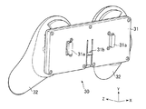
次に、タッチセンサ11と接触可能な操作部材を備えるアタッチメントをコアユニット10に取り付ける際における、操作部材のタッチセンサ11への接触を避けるための操作部材駆動機構の例について、説明する。図40A、図40B及び図40Cは、このような操作部材駆動機構の一例を示す図であって、図40Aは操作部材111を備えるアタッチメント110の斜視図を、図40Bはアタッチメント110をコアユニット10に取り付ける様子を示す断面図を、図40Cはアタッチメント110のコアユニット10への取り付けが完了した状態の断面図を、それぞれ示している。なお、図40Aにおいてはアタッチメント110の内部構造を示すためにカバー116を除いた状態が示されている。
Next, an example of an operation member drive mechanism for avoiding contact of the operation member with the
コアユニット10に取り付けられていない状態において、操作部材111を備えるプレート112は、支点115によってアタッチメント110のベース113に連結されており、バネ(不図示)によってベース113からわずかに離れるように上方に押し上げられている。また、プレート112はレバー114によって支持されている。レバー114の下端には爪114aが設けられており、この爪114aはベース113の底面より下側に突出している。アタッチメント110をコアユニット10に取り付ける際には、図40Bに示すように、コアユニット10の一方の端からアタッチメント110を図中矢印で示す向きにスライドさせて取り付けを行う。このとき、プレート112がベース113から浮いた状態になっているので、操作部材111の下端はタッチセンサ11から離れた位置に維持されている。ここで、さらにアタッチメント110をその全体がコアユニット10と重なる位置まで移動させると、爪114aがコアユニット10に押されることによってレバー114が回転し、プレート112を下方に押し下げる。このレバー114の作用により、アタッチメント110のコアユニット10への取り付けが完了する際にプレート112はタッチセンサ11に平行な向きに移動し、操作部材111の下端がタッチセンサ11の検出面に接触する。すなわち、操作部材111は、アタッチメント110の取り付けが完了するまではタッチセンサ11に接触せず、アタッチメント110への取り付けが完了するとタッチセンサ11に接触するようになる。
In a state where it is not attached to the
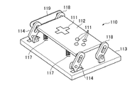
図41及び図42は、それぞれ操作部材駆動機構の別の例を示す図である。図41の例では、プレート112は爪を備える2本のレバー114、及び爪を備えていない2本のレバー118の計4本のレバーによって四隅を支持されており、バネ117によって上方に押し上げられている。その結果、アタッチメント110がコアユニット10に取り付けられていない状態では、プレート112はベース113と略平行でかつベース113から離れた位置に維持されている。このアタッチメント110をコアユニット10に取り付けると、図40A〜図40Cに示した例と同様に、2本のレバー114に設けられた爪がコアユニット10に押されてレバー114が回転する。このとき、平行リンク119によってレバー114の回転が爪を備えていないレバー118にも伝達され、その結果4本のレバーがいずれも回転してプレート112をタッチセンサ11側に押し下げる。このため、プレート112に配置された操作部材111がタッチセンサ11に接触するようになる。
41 and 42 are diagrams illustrating another example of the operation member driving mechanism. In the example of FIG. 41, the
図42の例では、プレート112が上下方向にのみ移動するように4本のガイドピン120によって四隅を支持されている。また、これらのガイドピン120の一部にはバネ117が取り付けられており、このバネ117の作用によってプレート112は上方に押し上げられている。このアタッチメント110がコアユニット10に取り付けられると、これまで説明した例と同様にレバー114の先端に設けられた爪がコアユニット10に押されてレバー114が回転し、プレート112を下方に押し下げる。このときプレート112は、ガイドピン120に沿ってタッチセンサ11に垂直な方向に移動する。これにより、プレート112に配置された操作部材111がタッチセンサ11に接触する。
In the example of FIG. 42, the four corners are supported by four
以上説明した操作部材駆動機構を適用することにより、例えば押圧操作ユニット90やスロットルレバーユニット100など、ユーザが操作部材の操作を行っていない間も操作部材がタッチセンサ11に接触するように配置されたアタッチメントをコアユニット10に取り付ける際にも、操作部材のコアユニット10への接触を避けることができ、スムーズにアタッチメントをコアユニット10に取り付けることができる。なお、ここで説明した操作部材駆動機構の構成はいずれも例示に過ぎず、他の方法でアタッチメントの取り付け時に操作部材がタッチセンサ11に接触しないようにしてもよい。例えば以上の説明ではバネの作用によってプレート112がベース113から離れた状態を維持することとしたが、バネ以外の弾性部材等を用いてもよい。
By applying the operation member driving mechanism described above, the operation member such as the
1 コントローラデバイス、2 情報処理装置、3 制御部、4 通信部、5 記憶部、6 表示装置、7 撮像装置、10 コアユニット、11 タッチセンサ、12 溝、13 取り付け部、13a 挿入口、14a 縦穴、14b 爪収容部、15 姿勢検出センサ、20 第1ボタンユニット、30 グリップユニット、40 第2ボタンユニット、50 3次元操作入力ユニット、60 補助グリップユニット、70 一体型3次元操作入力ユニット、80 スフィアユニット、90 押圧操作ユニット、100 スロットルレバーユニット。 DESCRIPTION OF SYMBOLS 1 Controller device, 2 Information processing apparatus, 3 Control part, 4 Communication part, 5 Storage part, 6 Display apparatus, 7 Imaging apparatus, 10 Core unit, 11 Touch sensor, 12 Groove, 13 Mounting part, 13a Insertion port, 14a Vertical hole , 14b Claw receiving portion, 15 posture detection sensor, 20 first button unit, 30 grip unit, 40 second button unit, 50 3D operation input unit, 60 auxiliary grip unit, 70 integrated 3D operation input unit, 80 sphere Unit, 90 pressing operation unit, 100 throttle lever unit.
Claims (13)
前記タッチセンサを覆うように前記コアユニットに取り付けられる第1のアタッチメントと、
を含み、情報処理装置と接続されるコントローラデバイスであって、
前記第1のアタッチメントは、
当該第1のアタッチメントが前記コアユニットに取り付けられた状態において前記タッチセンサに接触可能に構成され、ユーザの操作に伴ってその前記タッチセンサに対する接触態様が変化する操作部材を備え、
前記コアユニットは、
前記第1の表面に対する側面に配置される、前記タッチセンサを覆うように前記第1のアタッチメントを取り付けるための第1の取り付け機構と、
前記第1の表面の背面である第2の表面に配置される、前記第1のアタッチメントと異なる第2のアタッチメントを取り付けるための第2の取り付け機構と、
前記第2の表面であって前記第2の取り付け機構から離れた位置に配置される、前記第1のアタッチメントと異なる第3のアタッチメントを取り付けるための第3の取り付け機構と、を備え、
前記第2のアタッチメント及び前記第3のアタッチメントの少なくとも1つは、ユーザの操作対象となる操作部材を備える
ことを特徴とするコントローラデバイス。 A core unit having a touch sensor disposed on a first surface;
A first attachment attached to the core unit so as to cover the touch sensor;
A controller device connected to the information processing apparatus,
The first attachment is
The first attachment is configured to be able to contact the touch sensor in a state of being attached to the core unit, and includes an operation member whose contact mode with respect to the touch sensor changes according to a user operation,
The core unit is
A first attachment mechanism disposed on a side surface with respect to the first surface for attaching the first attachment so as to cover the touch sensor;
A second attachment mechanism for attaching a second attachment different from the first attachment, disposed on a second surface that is the back surface of the first surface;
A third attachment mechanism for attaching a third attachment different from the first attachment that is disposed on the second surface and away from the second attachment mechanism;
At least one of said 2nd attachment and said 3rd attachment is provided with the operation member used as a user's operation object. The controller device characterized by the above-mentioned.
前記第2のアタッチメント及び前記第3のアタッチメントの少なくとも1つは、ユーザが把持するための把持部を備える
ことを特徴とするコントローラデバイス。 The controller device of claim 1, wherein
The controller device, wherein at least one of the second attachment and the third attachment includes a grip part for a user to grip.
前記コアユニットは、
前記第1のアタッチメント、前記第2のアタッチメント、及び前記第3のアタッチメントそれぞれの種類を識別するための識別情報を取得する識別情報取得手段をさらに備え、
前記識別情報取得手段が取得した識別情報が、前記情報処理装置による前記第1のアタッチメント、前記第2のアタッチメント、及び前記第3のアタッチメントそれぞれの種類の識別に用いられる
ことを特徴とするコントローラデバイス。 The controller device according to claim 1 or 2,
The core unit is
An identification information acquisition means for acquiring identification information for identifying the type of each of the first attachment, the second attachment, and the third attachment;
The identification information acquired by the identification information acquisition unit is used for identification of each type of the first attachment, the second attachment, and the third attachment by the information processing apparatus. .
前記コアユニットは、前記取得した識別情報と、前記タッチセンサの検出結果と、前記ユーザの操作対象となる操作部材に対する操作内容と、を前記情報処理装置に提供し、
前記情報処理装置は、前記識別情報と前記検出結果とを組み合わせて用いることにより、前記第1のアタッチメントが備える操作部材に対する操作の内容と、を特定するとともに、前記識別情報と前記操作内容とを組み合わせて用いることにより前記第2のアタッチメントに備えられる操作部材に対する操作の内容と、前記第3のアタッチメントに備えられる操作部材に対する操作の内容と、を特定する、
ことを特徴とするコントローラデバイス。 The controller device of claim 3, wherein
The core unit provides the information processing apparatus with the acquired identification information, a detection result of the touch sensor, and an operation content for an operation member to be operated by the user,
The information processing apparatus uses the combination of the identification information and the detection result to specify the content of the operation on the operation member included in the first attachment, and uses the identification information and the operation content. the combination identifies the content of the operation to the operating member provided on the second attachment, and a content of the operation to the operating member provided on the third attachment by using it,
A controller device characterized by that.
前記操作部材は、前記第1のアタッチメントが前記コアユニットに取り付けられた状態において、前記ユーザの操作が行われていない間も前記タッチセンサの検出面に接触するように配置され、
前記第1のアタッチメントは、前記コアユニットへの取り付けが完了するまでは、前記操作部材を前記タッチセンサの検出面から離れた位置に維持し、前記コアユニットへの取り付けが完了する際に前記操作部材を前記タッチセンサの検出面に接触させる位置に移動させる機構を備える
ことを特徴とするコントローラデバイス。 The controller device according to any one of claims 1 to 4,
The operation member is arranged so as to contact the detection surface of the touch sensor even when the user operation is not performed in a state where the first attachment is attached to the core unit.
The first attachment maintains the operation member at a position away from the detection surface of the touch sensor until the attachment to the core unit is completed, and the operation is performed when the attachment to the core unit is completed. A controller device comprising a mechanism for moving a member to a position where the member comes into contact with the detection surface of the touch sensor.
前記タッチセンサを覆うように前記コアユニットに取り付けられる第1のアタッチメントと、
を含み、情報処理装置と接続されるコントローラデバイスであって、
前記第1のアタッチメントは、
当該第1のアタッチメントが前記コアユニットに取り付けられた状態において前記タッチセンサに接触可能に構成され、ユーザの操作に伴ってその前記タッチセンサに対する接触態様が変化する操作部材を備え、
前記操作部材は、前記第1のアタッチメントが前記コアユニットに取り付けられた状態において、前記ユーザの操作が行われていない間も前記タッチセンサの検出面に接触するように配置され、
前記第1のアタッチメントは、前記コアユニットへの取り付けが完了するまでは、前記操作部材を前記タッチセンサの検出面から離れた位置に維持し、前記コアユニットへの取り付けが完了する際に前記操作部材を前記タッチセンサの検出面に接触させる位置に移動させる機構を備える
ことを特徴とするコントローラデバイス。 A core unit with a touch sensor on one side;
A first attachment attached to the core unit so as to cover the touch sensor;
A controller device connected to the information processing apparatus,
The first attachment is
The first attachment is configured to be able to contact the touch sensor in a state of being attached to the core unit, and includes an operation member whose contact mode with respect to the touch sensor changes according to a user operation,
The operation member is arranged so as to contact the detection surface of the touch sensor even when the user operation is not performed in a state where the first attachment is attached to the core unit.
The first attachment maintains the operation member at a position away from the detection surface of the touch sensor until the attachment to the core unit is completed, and the operation is performed when the attachment to the core unit is completed. A controller device comprising a mechanism for moving a member to a position where the member comes into contact with the detection surface of the touch sensor.
前記コアユニットは、
前記第1のアタッチメントの種類を識別するための識別情報を取得する識別情報取得手段をさらに備え、
前記識別情報取得手段が取得した識別情報が、前記情報処理装置による前記第1のアタッチメントの種類の識別に用いられる
ことを特徴とするコントローラデバイス。 A controller device according to any one of claims 1 to 6, comprising:
The core unit is
An identification information acquisition means for acquiring identification information for identifying the type of the first attachment;
The controller device, wherein the identification information acquired by the identification information acquisition unit is used for identifying the type of the first attachment by the information processing apparatus.
前記第1のアタッチメントは、当該第1のアタッチメントが前記コアユニットに取り付けられた際に前記タッチセンサの所定位置に接触する接触部材をさらに備え、
前記識別情報取得手段は、前記接触部材が前記タッチセンサに接触する位置の情報を前記識別情報として取得する
ことを特徴とするコントローラデバイス。 The controller device of claim 7 , wherein
The first attachment further includes a contact member that contacts a predetermined position of the touch sensor when the first attachment is attached to the core unit.
The said identification information acquisition means acquires the information of the position where the said contact member contacts the said touch sensor as said identification information. The controller device characterized by the above-mentioned.
前記コアユニットは、前記取得した識別情報と、前記タッチセンサの検出結果と、を前記情報処理装置に提供し、
前記情報処理装置は、前記識別情報と前記検出結果とを組み合わせて用いることにより、前記第1のアタッチメントが備える操作部材に対する操作の内容を特定する
ことを特徴とするコントローラデバイス。 The controller device according to claim 7 or 8,
The core unit provides the acquired identification information and the detection result of the touch sensor to the information processing apparatus,
The said information processing apparatus specifies the content of operation with respect to the operation member with which a said 1st attachment is provided by using the said identification information and the said detection result in combination. The controller device characterized by the above-mentioned.
前記操作部材は、前記タッチセンサの検出面に平行な向きに沿ったユーザの操作に応じて、前記タッチセンサに対する接触位置が移動するように構成されている
ことを特徴とするコントローラデバイス。 The controller device according to any one of claims 1 to 9,
The controller device is configured such that a contact position with respect to the touch sensor moves in accordance with a user operation along a direction parallel to a detection surface of the touch sensor.
前記操作部材は、前記タッチセンサの検出面に対応する面状の操作領域を備え、当該操作領域内のいずれかの位置に対してユーザが押圧操作を行った場合に、当該押圧操作の位置に応じたタッチセンサの位置に対する接触態様が変化するよう構成されている
ことを特徴とするコントローラデバイス。 The controller device according to any one of claims 1 to 10,
The operation member includes a planar operation region corresponding to the detection surface of the touch sensor, and when the user performs a pressing operation on any position in the operation region, the operation member is positioned at the position of the pressing operation. A controller device configured to change a contact mode with respect to a position of a touch sensor in response.
前記操作部材は、前記押圧操作の強さに応じて、前記タッチセンサに対して加わる圧力、及び前記タッチセンサに対する接触面積のいずれか少なくとも一方が変化するように構成されており、
前記タッチセンサは、前記操作部材が検出面に加える圧力、及び前記操作部材の接触面積のいずれか少なくとも一方の大きさを検出する
ことを特徴とするコントローラデバイス。 The controller device of claim 11, wherein
The operation member is configured such that at least one of the pressure applied to the touch sensor and the contact area with respect to the touch sensor changes according to the strength of the pressing operation.
The controller device, wherein the touch sensor detects at least one of a pressure applied to the detection surface by the operation member and a contact area of the operation member.
タッチセンサと、
前記第1の表面に対する側面に配置される、前記タッチセンサの少なくとも一部を覆う位置に前記第1のアタッチメントを取り付けるための第1の取り付け機構と、
前記第1の表面の背面である第2の表面に配置される、前記第1のアタッチメントと異なる第2のアタッチメントを取り付けるための第2の取り付け機構と、
前記第2の表面であって前記第2の取り付け機構から離れた位置に配置される、前記第1のアタッチメントと異なる第3のアタッチメントを取り付けるための第3の取り付け機構と、
を備え、
前記操作部材は、前記第1のアタッチメントが当該コアユニットに取り付けられた状態において前記タッチセンサに接触可能に構成され、
前記タッチセンサは、ユーザの操作に伴う前記操作部材の前記タッチセンサに対する接触態様の変化を検出する、
ことを特徴とするコントローラデバイスのコアユニット。 A core unit of a controller device that is connected to an information processing apparatus and uses a first attachment having an operation member attached to a first surface ,
A touch sensor;
A first attachment mechanism for attaching the first attachment to a position covering at least a part of the touch sensor, which is disposed on a side surface with respect to the first surface;
A second attachment mechanism for attaching a second attachment different from the first attachment, disposed on a second surface that is the back surface of the first surface;
A third attachment mechanism for attaching a third attachment different from the first attachment, disposed on the second surface and at a position away from the second attachment mechanism;
With
The operation member is configured to be able to contact the touch sensor in a state where the first attachment is attached to the core unit.
The touch sensor detects a change in the contact mode with respect to the touch sensor of the operation member with the operation of the User chromatography THE,
A core unit of a controller device characterized by that.
Priority Applications (4)
| Application Number | Priority Date | Filing Date | Title |
|---|---|---|---|
| JP2011126038A JP5896446B2 (en) | 2011-06-06 | 2011-06-06 | Controller device |
| PCT/JP2012/063355 WO2012169367A1 (en) | 2011-06-06 | 2012-05-24 | Controller device |
| CN201280024897.0A CN103561830B (en) | 2011-06-06 | 2012-05-24 | Controller equiment |
| US14/117,913 US20140094309A1 (en) | 2011-06-06 | 2012-05-24 | Controller device |
Applications Claiming Priority (1)
| Application Number | Priority Date | Filing Date | Title |
|---|---|---|---|
| JP2011126038A JP5896446B2 (en) | 2011-06-06 | 2011-06-06 | Controller device |
Publications (3)
| Publication Number | Publication Date |
|---|---|
| JP2012249922A JP2012249922A (en) | 2012-12-20 |
| JP2012249922A5 JP2012249922A5 (en) | 2014-09-11 |
| JP5896446B2 true JP5896446B2 (en) | 2016-03-30 |
Family
ID=47523329
Family Applications (1)
| Application Number | Title | Priority Date | Filing Date |
|---|---|---|---|
| JP2011126038A Active JP5896446B2 (en) | 2011-06-06 | 2011-06-06 | Controller device |
Country Status (1)
| Country | Link |
|---|---|
| JP (1) | JP5896446B2 (en) |
Families Citing this family (5)
| Publication number | Priority date | Publication date | Assignee | Title |
|---|---|---|---|---|
| JP6051016B2 (en) * | 2012-10-30 | 2016-12-21 | 任天堂株式会社 | Information processing system, game system, and information processing apparatus |
| JP6187867B2 (en) * | 2013-10-31 | 2017-08-30 | グンゼ株式会社 | Brushed sheet and input device |
| JP6533539B2 (en) * | 2017-01-26 | 2019-06-19 | 任天堂株式会社 | Attachment and operation system |
| JP6861146B2 (en) * | 2017-12-19 | 2021-04-21 | 任天堂株式会社 | Attachment and operation system |
| JP6861240B2 (en) * | 2019-05-24 | 2021-04-21 | 任天堂株式会社 | Attachment and operation system |
Family Cites Families (11)
| Publication number | Priority date | Publication date | Assignee | Title |
|---|---|---|---|---|
| JP3320617B2 (en) * | 1996-09-12 | 2002-09-03 | 株式会社東芝 | Input device |
| JPH1153994A (en) * | 1997-07-31 | 1999-02-26 | Sega Enterp Ltd | Operation device and grip for the same |
| JP3209149B2 (en) * | 1997-08-06 | 2001-09-17 | 日本電気株式会社 | Mobile terminal device |
| JP3269482B2 (en) * | 1999-03-18 | 2002-03-25 | 日本電気株式会社 | Keyboard device |
| JP3665539B2 (en) * | 2000-06-19 | 2005-06-29 | シャープ株式会社 | Input device |
| JP2002325286A (en) * | 2001-04-26 | 2002-11-08 | Casio Comput Co Ltd | Portable device and remote control processing program |
| JP2003273980A (en) * | 2002-03-13 | 2003-09-26 | Mitsumi Electric Co Ltd | Game controller for mobile phone |
| WO2006077686A1 (en) * | 2005-01-20 | 2006-07-27 | Yamaha Corporation | Portable electronic device |
| JP2007207107A (en) * | 2006-02-03 | 2007-08-16 | Matsushita Electric Ind Co Ltd | Portable terminal |
| US20100277428A1 (en) * | 2007-08-31 | 2010-11-04 | Itsuo Kumazawa | Touch panel input assisting device, computer operating method using the device, and tactile sense interlocking program |
| JP5464684B2 (en) * | 2008-09-19 | 2014-04-09 | 株式会社ソニー・コンピュータエンタテインメント | Input device and input operation auxiliary panel |
-
2011
- 2011-06-06 JP JP2011126038A patent/JP5896446B2/en active Active
Also Published As
| Publication number | Publication date |
|---|---|
| JP2012249922A (en) | 2012-12-20 |
Similar Documents
| Publication | Publication Date | Title |
|---|---|---|
| WO2012169367A1 (en) | Controller device | |
| JP2012249923A (en) | Controller device | |
| JP7199476B2 (en) | Control system, control device, control method, and program | |
| JP5896446B2 (en) | Controller device | |
| KR101666096B1 (en) | System and method for enhanced gesture-based interaction | |
| JP6574892B2 (en) | Control device and control program | |
| EP1816552B1 (en) | Storage medium storing subject selecting program and subject selecting apparatus | |
| US20160077589A1 (en) | Multidimension vibrating mouse | |
| CN110622231B (en) | Programming device, recording medium, and programming method | |
| WO2013157053A1 (en) | Game system and game controller | |
| CN110226150B (en) | Controller | |
| TWI404560B (en) | Operation device | |
| US20090267805A1 (en) | Control apparatus and electronic device using the same | |
| US20160328028A1 (en) | System, method and device for foot-operated motion and movement control in virtual reality and simulated environments | |
| US6184869B1 (en) | Computer input device having multiple multi-dimensional detection devices | |
| JP2012073830A (en) | Interface device | |
| US10191557B2 (en) | User interface device | |
| TW201921227A (en) | User input devices, panels for use with a user input device and computer peripheral devices | |
| JP4940294B2 (en) | Information processing system, operation device, and information processing method | |
| JP5200195B1 (en) | Game system, game controller | |
| JP2005293512A (en) | Finger-worn type data input device | |
| US8333664B2 (en) | Information processing apparatus, control method therefor, operation device, and information storage medium | |
| KR20010042305A (en) | Data input device and method, and computer system using the same and method for running program of computer system | |
| US20130027307A1 (en) | Human-machine interface apparatus and operating method thereof | |
| KR20230020844A (en) | Motion controller |
Legal Events
| Date | Code | Title | Description |
|---|---|---|---|
| A621 | Written request for application examination |
Free format text: JAPANESE INTERMEDIATE CODE: A621 Effective date: 20140606 |
|
| A521 | Written amendment |
Free format text: JAPANESE INTERMEDIATE CODE: A523 Effective date: 20140724 |
|
| A131 | Notification of reasons for refusal |
Free format text: JAPANESE INTERMEDIATE CODE: A131 Effective date: 20150616 |
|
| A521 | Written amendment |
Free format text: JAPANESE INTERMEDIATE CODE: A523 Effective date: 20150817 |
|
| A131 | Notification of reasons for refusal |
Free format text: JAPANESE INTERMEDIATE CODE: A131 Effective date: 20151104 |
|
| A521 | Written amendment |
Free format text: JAPANESE INTERMEDIATE CODE: A523 Effective date: 20151221 |
|
| TRDD | Decision of grant or rejection written | ||
| A01 | Written decision to grant a patent or to grant a registration (utility model) |
Free format text: JAPANESE INTERMEDIATE CODE: A01 Effective date: 20160126 |
|
| A61 | First payment of annual fees (during grant procedure) |
Free format text: JAPANESE INTERMEDIATE CODE: A61 Effective date: 20160225 |
|
| R150 | Certificate of patent or registration of utility model |
Ref document number: 5896446 Country of ref document: JP Free format text: JAPANESE INTERMEDIATE CODE: R150 |
|
| R250 | Receipt of annual fees |
Free format text: JAPANESE INTERMEDIATE CODE: R250 |
|
| R250 | Receipt of annual fees |
Free format text: JAPANESE INTERMEDIATE CODE: R250 |
|
| R250 | Receipt of annual fees |
Free format text: JAPANESE INTERMEDIATE CODE: R250 |
|
| R250 | Receipt of annual fees |
Free format text: JAPANESE INTERMEDIATE CODE: R250 |