JP5895112B1 - Fuel cell - Google Patents
Fuel cell Download PDFInfo
- Publication number
- JP5895112B1 JP5895112B1 JP2016000149A JP2016000149A JP5895112B1 JP 5895112 B1 JP5895112 B1 JP 5895112B1 JP 2016000149 A JP2016000149 A JP 2016000149A JP 2016000149 A JP2016000149 A JP 2016000149A JP 5895112 B1 JP5895112 B1 JP 5895112B1
- Authority
- JP
- Japan
- Prior art keywords
- seal
- film
- recess
- solid electrolyte
- electrical connection
- Prior art date
- Legal status (The legal status is an assumption and is not a legal conclusion. Google has not performed a legal analysis and makes no representation as to the accuracy of the status listed.)
- Expired - Fee Related
Links
Images


Classifications
-
- Y—GENERAL TAGGING OF NEW TECHNOLOGICAL DEVELOPMENTS; GENERAL TAGGING OF CROSS-SECTIONAL TECHNOLOGIES SPANNING OVER SEVERAL SECTIONS OF THE IPC; TECHNICAL SUBJECTS COVERED BY FORMER USPC CROSS-REFERENCE ART COLLECTIONS [XRACs] AND DIGESTS
- Y02—TECHNOLOGIES OR APPLICATIONS FOR MITIGATION OR ADAPTATION AGAINST CLIMATE CHANGE
- Y02E—REDUCTION OF GREENHOUSE GAS [GHG] EMISSIONS, RELATED TO ENERGY GENERATION, TRANSMISSION OR DISTRIBUTION
- Y02E60/00—Enabling technologies; Technologies with a potential or indirect contribution to GHG emissions mitigation
- Y02E60/30—Hydrogen technology
- Y02E60/50—Fuel cells
Abstract
【課題】「横縞型」の燃料電池であって、「中間焼成体」の外側面における反応防止膜の外縁の近傍部分にてクラックが発生し難いものを提供すること。【解決手段】支持基板10の主面に形成された各第1凹部12に、対応する発電素子部Aの燃料極20がそれぞれ埋設される。燃料ガスと空気との混合を防止する「シール部」は、インターコネクタ30と、固体電解質膜40と、反応防止膜50と、により構成される。固体電解質膜40の外側面における「各発電素子部Aに対応するそれぞれの領域を含んだ部分」に第2凹部が形成される。この第2凹部に反応防止膜50が埋設される。第2凹部は、固体電解質膜40の材料からなる底壁41と、全周に亘って固体電解質膜40の材料からなる周方向に閉じた側壁42、43と、を有する。【選択図】図3The present invention provides a “horizontal stripe type” fuel cell in which cracks are unlikely to occur in the vicinity of the outer edge of a reaction preventing film on the outer surface of an “intermediate fired body”. A fuel electrode 20 of a corresponding power generation element portion A is embedded in each first recess 12 formed on the main surface of a support substrate 10. The “seal part” that prevents the fuel gas and the air from being mixed includes the interconnector 30, the solid electrolyte membrane 40, and the reaction prevention membrane 50. A second recess is formed in “a portion including each region corresponding to each power generation element portion A” on the outer surface of the solid electrolyte membrane 40. The reaction preventing film 50 is embedded in the second recess. The second recess has a bottom wall 41 made of the material of the solid electrolyte membrane 40 and side walls 42 and 43 closed in the circumferential direction made of the material of the solid electrolyte membrane 40 over the entire circumference. [Selection] Figure 3
Description
本発明は、燃料電池に関する。 The present invention relates to a fuel cell.
従来より、「長手方向を有する支持基板であって、ガス流路が前記長手方向に沿って内部に形成された支持基板」と、「前記支持基板の主面における互いに離れた複数の箇所にそれぞれ設けられ、少なくとも燃料極、緻密質材料からなる固体電解質膜、希土類元素を含むセリアを含んだ緻密質材料からなる反応防止膜、及び、空気極がこの順に積層された複数の発電素子部」と、「隣り合う前記発電素子部の一方の燃料極と他方の空気極とを電気的に接続する1つ又は複数の電気的接続部」と、「前記支持基板の主面を覆うように設けられ、前記ガス流路を経て前記燃料極に供給されるガスと、前記空気極に供給されるガスと、の混合を防止する、緻密質材料からなるシール部」と、を備えた、焼成体である燃料電池が広く知られている(例えば、特許文献1を参照)。このような構成は、「横縞型」とも呼ばれる。 Conventionally, “a support substrate having a longitudinal direction and a gas flow path formed therein along the longitudinal direction” and “a plurality of locations separated from each other on the main surface of the support substrate, respectively” A plurality of power generating element portions provided with at least a fuel electrode, a solid electrolyte membrane made of a dense material, a reaction preventing film made of a dense material containing ceria containing a rare earth element, and an air electrode in this order. '' , “One or more electrical connection portions that electrically connect one fuel electrode and the other air electrode of the adjacent power generation element portions” and “is provided so as to cover the main surface of the support substrate. And a seal part made of a dense material that prevents mixing of the gas supplied to the fuel electrode through the gas flow path and the gas supplied to the air electrode. A fuel cell is widely known (example If, refer to Patent Document 1). Such a configuration is also called a “horizontal stripe type”.
上記文献に記載された燃料電池では、前記各電気的接続部は、緻密質材料からなる第1部分(インターコネクタ)と、前記第1部分と接続され且つ多孔質材料からなる第2部分(空気極集電膜)とで構成される。前記第1部分は、前記隣り合う発電素子部の一方の燃料極と前記第2部分とに接続される。前記第2部分は、前記隣り合う発電素子部の他方の空気極と前記第1部分とに接続される。 In the fuel cell described in the above document, each of the electrical connection portions includes a first portion (interconnector) made of a dense material and a second portion (air) connected to the first portion and made of a porous material. Electrode current collector film). The first part is connected to one fuel electrode of the adjacent power generation element part and the second part. The second part is connected to the other air electrode of the adjacent power generation element part and the first part.
前記支持基板の主面における前記複数の箇所に、前記支持基板の材料からなる底壁と、全周に亘って前記支持基板の材料からなる周方向に閉じた側壁と、を有する第1凹部がそれぞれ形成されている。前記各第1凹部に、対応する前記発電素子部の前記燃料極がそれぞれ埋設されている。 A first recess having a bottom wall made of the material of the support substrate and a side wall closed in the circumferential direction made of the material of the support substrate over the entire circumference at the plurality of locations on the main surface of the support substrate. Each is formed. The fuel electrode of the corresponding power generation element portion is embedded in each first recess.
前記シール部は、「前記各電気的接続部のそれぞれの第1部分」と、「前記各発電素子部に含まれるそれぞれの前記固体電解質膜を含むとともに前記それぞれの前記固体電解質膜から連続して延設された前記固体電解質と同じ緻密質材料からなる第1シール膜」と、「前記各発電素子部に含まれるそれぞれの前記反応防止膜を含むとともに前記それぞれの前記反応防止膜から連続して延設された前記反応防止膜と同じ緻密質材料からなる第2シール膜」と、を含んで構成されている。 The seal portion includes “the first portions of the respective electrical connection portions” and “the respective solid electrolyte membranes included in the respective power generation element portions and continuously from the respective solid electrolyte membranes. A first seal film made of the same dense material as the solid electrolyte extended, and “including each of the reaction prevention films included in each of the power generation element portions and continuously from each of the reaction prevention films. A second sealing film made of the same dense material as the extended reaction preventing film ”.
上記文献に記載された燃料電池では、通常、支持基板の成形体に、燃料極の成形体と、シール部(各電気的接続部のそれぞれの第1部分、第1シール膜、及び、第2シール膜を含む)の成形体とが積層された段階で、この積層体(グリーン体)が焼成される。その後、この焼成体(以下、「中間焼成体」と呼ぶ)に、空気極の成形体と、各電気的接続部のそれぞれの第2部分の成形体とが積層され、この新たな積層体(グリーン体)が、前述の焼成時よりも低い温度で焼成される。これにより、焼成体である燃料電池が完成する。 In the fuel cell described in the above-mentioned document, usually, a molded body of the support substrate, a molded body of the fuel electrode, and a seal portion (the first portion of each electrical connection portion, the first seal film, and the second The laminated body (green body) is fired at the stage where the molded body (including the sealing film) is laminated. Thereafter, the fired body (hereinafter referred to as “intermediate fired body”) is laminated with a molded body of the air electrode and a molded body of each second part of each electrical connection portion, and this new laminated body ( The green body) is fired at a temperature lower than that at the time of firing described above. Thereby, the fuel cell which is a sintered body is completed.
ところで、上記文献に記載された燃料電池では、シール部の一部である第1シール膜(固体電解質膜を含む)、及び、第2シール膜(反応防止膜を含む)に関し、第1シール膜の外側面(平面)上に第2シール膜が積層されている。この結果、「中間焼成体」の外側面における第2シール膜の外縁にて、第2シール膜の厚さに相当する段差が存在している。 By the way, in the fuel cell described in the above document, the first seal film is related to the first seal film (including the solid electrolyte film) and the second seal film (including the reaction preventing film) which are part of the seal portion. A second seal film is laminated on the outer side surface (flat surface). As a result, there is a step corresponding to the thickness of the second seal film at the outer edge of the second seal film on the outer surface of the “intermediate fired body”.
ここで、「中間焼成体」の焼成時にて、「中間焼成体」の外側面における第2シール膜の外縁の近傍部分にてクラックが発生し易い、という問題があった。これは、上述した段差の高さが大きいことに起因して、焼成中にて、「中間焼成体」の外側面における第2シール膜の外縁の近傍部分にて過大な応力が局所的に発生し易いことに基づく、と考えられる。 Here, when the “intermediate fired body” is fired, there is a problem that cracks are likely to occur in the vicinity of the outer edge of the second seal film on the outer surface of the “intermediate fired body”. This is because the height of the step is large, and excessive stress is locally generated in the vicinity of the outer edge of the second seal film on the outer surface of the “intermediate fired body” during firing. It is thought that it is based on what is easy to do.
本発明は、以上の問題に対処するためのものであり、「横縞型」の燃料電池であって、「中間焼成体」の外側面における第2シール膜の外縁の近傍部分にてクラックが発生し難いものを提供することを目的とする。 The present invention is to cope with the above problems, and is a “horizontal stripe type” fuel cell in which cracks are generated in the vicinity of the outer edge of the second seal film on the outer surface of the “intermediate fired body”. The purpose is to provide something difficult to do.
本発明に係る燃料電池は、「背景技術」の欄で記載した燃料電池と同様に、前記「支持基板」と、前記「複数の発電素子部」と、前記「複数の電気的接続部」と、前記「シール部」と、を備えた、「横縞型」の燃料電池である。 The fuel cell according to the present invention includes the “support substrate”, the “plurality of power generation element portions”, and the “plurality of electrical connection portions”, as in the fuel cell described in the “Background Art” section. A “horizontal stripe type” fuel cell comprising the “seal portion”.
本発明に係る燃料電池の特徴は、前記第1シール膜の外側面における前記各発電素子部に対応するそれぞれの領域を含んだ部分に、前記第1シール膜の材料からなる底壁と、前記第1シール膜の材料からなり且つ周方向に閉じた側壁と、を有する第2凹部が形成され、前記第2凹部に、前記第2シール膜が埋設されたことにある。この結果、前記各電気的接続部のそれぞれの第1部分の外側面と、前記第1シール膜の外側面における前記第2凹部以外の部分と、前記第2凹部に埋設された前記第2シール膜の外側面と、を含んで、前記シール部の外側面が構成されている。 The fuel cell according to the present invention is characterized in that a portion of the outer surface of the first seal film including a region corresponding to each power generation element portion includes a bottom wall made of the material of the first seal film, A second recess having a side wall made of a material of the first seal film and closed in the circumferential direction is formed, and the second seal film is embedded in the second recess. As a result, the outer surface of the first portion of each of the electrical connection portions, the portion other than the second recess on the outer surface of the first seal film, and the second seal embedded in the second recess An outer surface of the membrane, and the outer surface of the seal portion is configured.
上記本発明の特徴によれば、例えば、第2凹部に、第2シール膜における厚さ方向の全域が埋設される場合、「中間焼成体」の外側面における第2シール膜の外縁にて段差が形成されない。また、第2凹部に、第2シール膜における厚さ方向の一部のみが埋設される場合(即ち、第2シール膜における厚さ方向の内側部分が第2凹部に埋設され、第2シール膜における厚さ方向の外側部分が第1シール膜の外側面に対して厚さ方向に突出している場合)においても、上述した文献に記載された燃料電池の構成(即ち、第2シール膜における厚さ方向の全域が第1シール膜の外側面に対して厚さ方向に突出している場合)と比べて、「中間焼成体」の外側面における第2シール膜の外縁にて形成される段差の高さが小さくなる。 According to the above feature of the present invention, for example, when the whole area in the thickness direction of the second seal film is embedded in the second recess, a step is formed at the outer edge of the second seal film on the outer surface of the “intermediate fired body”. Is not formed. In addition, when only a part of the second seal film in the thickness direction is embedded in the second recess (that is, the inner part of the second seal film in the thickness direction is embedded in the second recess, and the second seal film Even in the case where the outer portion in the thickness direction in FIG. 3 protrudes in the thickness direction with respect to the outer surface of the first seal film), the structure of the fuel cell described in the above-described document (that is, the thickness in the second seal film) Compared to the case where the entire area in the vertical direction protrudes in the thickness direction with respect to the outer surface of the first seal film), the level difference formed at the outer edge of the second seal film on the outer surface of the “intermediate fired body” The height becomes smaller.
このように、何れにしろ、上記本発明の特徴によれば、上述した文献に記載された燃料電池の構成と比べて、「中間焼成体」の外側面における第2シール膜の外縁にて形成される段差の高さが小さくなる。この結果、前記第2シール膜の外縁の近傍部分にて過大な応力が局所的に発生し難くなり、前記外縁の近傍部分にてクラックが発生し難くなる。 Thus, in any case, according to the above-described feature of the present invention, it is formed at the outer edge of the second seal film on the outer surface of the “intermediate fired body” as compared with the configuration of the fuel cell described in the above-mentioned document. The height of the step is reduced. As a result, excessive stress is unlikely to occur locally in the vicinity of the outer edge of the second seal film, and cracks are unlikely to occur in the vicinity of the outer edge.
この場合、前記各電気的接続部のそれぞれの第1部分の外側面と、前記第1シール膜の外側面における前記第2凹部以外の部分と、前記第2凹部に埋設された前記第2シール膜の外側面と、により、前記シール部の連続した外側面が構成されることが好適である。これによれば、「中間焼成体」の外側面の全域において「段差」が存在しない。従って、焼成中にて、「中間焼成体」の外側面の全域において「段差」の存在に起因する過大な応力が発生し難くなる。この結果、「中間焼成体」の外側面の全域において「段差」の存在に起因するクラックが発生し難くなる。 In this case, the outer surface of the first portion of each of the electrical connection portions, the portion other than the second recess portion on the outer surface of the first seal film, and the second seal embedded in the second recess portion. It is preferable that the outer surface of the membrane constitutes a continuous outer surface of the seal portion. According to this, there is no “step” in the entire outer surface of the “intermediate fired body”. Accordingly, it is difficult to generate excessive stress due to the presence of “steps” in the entire outer surface of the “intermediate fired body” during firing. As a result, cracks due to the presence of “steps” are less likely to occur across the entire outer surface of the “intermediate fired body”.
上記本発明に係る燃料電池においては、前記第2凹部は、前記第1シール膜の材料からなる底壁と、全周に亘って前記第1シール膜の材料からなる周方向に閉じた側壁と、を有することが好適である。 In the fuel cell according to the present invention, the second recess includes a bottom wall made of the material of the first seal film, and a side wall closed in the circumferential direction made of the material of the first seal film over the entire circumference. It is preferable to have
上記本発明における燃料電池では、シール部で区画されるシール部の内側領域が還元雰囲気になり、シール部で区画されるシール部の外側領域が酸化雰囲気になる。ここで、第2シール膜は、反応防止膜を構成する「セリアを含んだ材料」(例えば、ガドリニウム・ドープ・セリア(GDC))で構成されている。一般に、「セリアを含んだ材料」は、還元雰囲気に曝されると、膨張し易い。従って、第2シール膜を還元雰囲気に曝すと、自身の膨張に起因して、第2シール膜の剥離、及び反り等が発生し易い。この点、上記構成によれば、第2シール膜の側面の全周が第1シール膜で構成される枠体で確実に覆われ得る。従って、第2シール膜が、シール部(第1シール膜)の内側領域の雰囲気(即ち、還元雰囲気)に曝され難くなる。この結果、上述した「第2シール膜の剥離、及び反り等」が発生し難くなる。 In the fuel cell according to the present invention, the inner region of the seal portion defined by the seal portion is a reducing atmosphere, and the outer region of the seal portion defined by the seal portion is an oxidizing atmosphere. Here, the second seal film is made of a “ceria-containing material” (for example, gadolinium-doped ceria (GDC)) constituting the reaction preventing film. In general, a “material containing ceria” tends to expand when exposed to a reducing atmosphere. Therefore, when the second seal film is exposed to a reducing atmosphere, the second seal film is likely to be peeled off and warped due to its expansion. In this regard, according to the above configuration, the entire circumference of the side surface of the second seal film can be reliably covered with the frame body formed of the first seal film. Therefore, the second seal film is not easily exposed to the atmosphere (that is, the reducing atmosphere) in the inner region of the seal portion (first seal film). As a result, the above-mentioned “peeling of the second seal film, warping, etc.” is less likely to occur.
また、上記本発明に係る燃料電池においては、前記シール部は、前記各電気的接続部の第1部分及び前記第1シール膜と接続するとともに前記第1、第2シール膜とは異なる緻密質材料からなる複数の第3シール部を備え、前記第1シール膜と前記各電気的接続部の第1部分とは接触しないように構成されることが好適である。この場合、前記各電気的接続部のそれぞれの第1部分の外側面と、前記第1シール膜の外側面における前記第2凹部以外の部分と、前記第2凹部に埋設された前記第2シール膜の外側面と、前記各第3シール部のそれぞれの外側面と、により、前記シール部の外側面が構成され得る。 Moreover, in the fuel cell according to the present invention, the seal portion is connected to the first portion of each electrical connection portion and the first seal film, and is denser than the first and second seal films. It is preferable that a plurality of third seal portions made of a material are provided so that the first seal film and the first portions of the respective electrical connection portions are not in contact with each other. In this case, the outer surface of the first portion of each of the electrical connection portions, the portion other than the second recess portion on the outer surface of the first seal film, and the second seal embedded in the second recess portion. The outer surface of the seal portion may be constituted by the outer surface of the membrane and the outer surface of each of the third seal portions.
一般に、電気的接続部の第1部分(インターコネクタ)は、ランタンクロマイトで構成され、第1シール膜(即ち、固体電解質膜)は、イットリア安定化ジルコニアで構成され得る。ここで、ランタンクロマイトがジルコニアと接触すると、ランタンクロマイトの焼結性が低下し、ランタンクロマイトの緻密性が失われ易い。この点、上記構成によれば、前記第3シール部の導入によって、前記第1シール膜と前記各電気的接続部の第1部分とが接触しないように構成される。この結果、電気的接続部の第1部分と第1シール膜との接触に起因して電気的接続部の第1部分の緻密性が失われる、という問題が発生し難くなる。 In general, the first portion (interconnector) of the electrical connection portion is made of lanthanum chromite, and the first seal membrane (ie, the solid electrolyte membrane) can be made of yttria-stabilized zirconia. Here, when lanthanum chromite comes into contact with zirconia, the sinterability of lanthanum chromite is lowered, and the denseness of lanthanum chromite is easily lost. In this regard, according to the above configuration, the introduction of the third seal portion prevents the first seal film from contacting the first portion of each electrical connection portion. As a result, the problem that the denseness of the first portion of the electrical connection portion is lost due to the contact between the first portion of the electrical connection portion and the first seal film is less likely to occur.
(実施形態の構成)
図1は、本発明に係る固体酸化物形燃料電池(SOFC)の実施形態(本実施形態)を示す。このSOFC100は、長手方向(x軸方向)を有する平板状の支持基板10の上下面(互いに平行な両側の主面(平面))のそれぞれに、電気的に直列に接続された複数(本例では、4つ)の同形の発電素子部Aが長手方向において所定の間隔をおいて配置された、所謂「横縞型」と呼ばれる構成を有する。
(Configuration of the embodiment)
FIG. 1 shows an embodiment (this embodiment) of a solid oxide fuel cell (SOFC) according to the present invention. The
SOFC100の全体を上方からみた形状は、例えば、長手方向の辺の長さが5〜50cmで長手方向に直交する幅方向(y軸方向)の長さが1〜10cmの長方形である。SOFC100の全体の厚さは、1〜5mmである。SOFC100の全体は、厚さ方向の中心を通り且つ支持基板10の主面に平行な面に対して上下対称の形状を有する。以下、図1〜図6を参照しながら、SOFC100の詳細について説明する。
The shape of the
図1〜図3に示すように、支持基板10は、電子伝導性を有さない多孔質の材料からなる平板状の焼成体である。後述する図10に示すように、支持基板10は、長手方向(x軸方向)を有する平板状の主部10Aと、主部10Aにおける幅方向(y軸方向)の両端部に位置し主部10Aと接続する一対の側端部10B、10Bと、から構成される。
As shown in FIGS. 1 to 3, the
側端部10Bは、長手方向(x軸方向)に延びる半円柱状を呈している。側端部10Bの幅方向に突出する曲面(円筒面の一部)の曲率半径は、0.3〜5mmである。主部10Aと一対の側端部10B、10Bそれぞれとの境界部には、側端部10Bが主部10Aに対して厚さ方向(z軸方向)に突出し、且つ側端部10Bが長手方向(x軸方向)に延びるように、一対の段差ST、STが形成されている。
The
支持基板10の主部10Aの内部には、長手方向(x軸方向)に延びる複数(本例では、6本)の燃料ガス流路11(貫通孔)が幅方向において所定の間隔をおいて形成されている。また、支持基板10の主部10Aの上下面(両主面)のそれぞれには、各発電素子部Aに対応する箇所に凹部12(前記「第1凹部」に対応)がそれぞれ形成されている。本例では、各凹部12は、支持基板10の材料からなる底壁と、全周に亘って支持基板10の材料からなる周方向に閉じた側壁(長手方向に沿う2つの側壁と幅方向に沿う2つの側壁)と、で画定された直方体状の窪みである。
Inside the
支持基板10は、例えば、CSZ(カルシア安定化ジルコニア)から構成され得る。或いは、NiO(酸化ニッケル)とYSZ(8YSZ)(イットリア安定化ジルコニア)とから構成されてもよいし、NiO(酸化ニッケル)とY2O3(イットリア)とから構成されてもよいし、MgO(酸化マグネシウム)とMgAl2O4(マグネシアアルミナスピネル)とから構成されてもよい。
The
支持基板10は、「遷移金属酸化物又は遷移金属」と、絶縁性セラミックスとを含んで構成され得る。「遷移金属酸化物又は遷移金属」としては、NiO(酸化ニッケル)又はNi(ニッケル)が好適である。遷移金属は、燃料ガスの改質反応を促す触媒(炭化水素系のガスの改質触媒)として機能し得る。
The
また、絶縁性セラミックスとしては、MgO(酸化マグネシウム)、又は、「MgAl2O4(マグネシアアルミナスピネル)とMgO(酸化マグネシウム)の混合物」が好適である。また、絶縁性セラミックスとして、CSZ(カルシア安定化ジルコニア)、YSZ(8YSZ)(イットリア安定化ジルコニア)、Y2O3(イットリア)が使用されてもよい。 Further, as the insulating ceramic, MgO (magnesium oxide) or “mixture of MgAl 2 O 4 (magnesia alumina spinel) and MgO (magnesium oxide)” is preferable. Further, CSZ (calcia stabilized zirconia), YSZ (8YSZ) (yttria stabilized zirconia), Y 2 O 3 (yttria) may be used as the insulating ceramic.
このように、支持基板10が「遷移金属酸化物又は遷移金属」を含むことによって、改質前の残存ガス成分を含んだガスが多孔質の支持基板10の内部の多数の気孔を介して燃料ガス流路11から燃料極に供給される過程において、上記触媒作用によって改質前の残存ガス成分の改質を促すことができる。加えて、支持基板10が絶縁性セラミックスを含むことによって、支持基板10の絶縁性を確保することができる。この結果、隣り合う燃料極間における絶縁性が確保され得る。支持基板10の厚さは、1〜5mmである。
As described above, since the
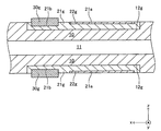
図2〜図5に示すように、支持基板10の上下面(両主面)に形成された各凹部12には、燃料極集電部21の全体が埋設(充填)されている。従って、各燃料極集電部21は直方体状を呈している。図3及び図5に示すように、各燃料極集電部21の表面(外側面)には、凹部21aが形成されている。各凹部21aは、燃料極集電部21の材料からなる底壁と、周方向に閉じた側壁(長手方向に沿う2つの側壁と幅方向に沿う2つの側壁)と、で画定された直方体状の窪みである。前記「周方向に閉じた側壁」は、全周に亘って燃料極集電部21の材料からなる。
As shown in FIGS. 2 to 5, the entire fuel electrode
各凹部21aには、燃料極活性部22の全体(厚さ方向(z軸方向)における全域)が埋設(充填)されている。従って、各燃料極活性部22は直方体状を呈している。燃料極集電部21と燃料極活性部22とにより燃料極20が構成される。燃料極20(燃料極集電部21+燃料極活性部22)は、電子伝導性を有する多孔質の材料からなる焼成体である。各燃料極活性部22の前記「周方向に閉じた側壁」の全周と底面とは、凹部21a内で燃料極集電部21と接触している。
In each
図3及び図5に示すように、各燃料極集電部21の表面(外側面)における凹部21aを除いた部分には、凹部21bが形成されている。各凹部21bは、燃料極集電部21の材料からなる底壁と、周方向に閉じた側壁(長手方向に沿う2つの側壁と幅方向に沿う2つの側壁)と、で画定された直方体状の窪みである。前記「周方向に閉じた側壁」は、全周に亘って燃料極集電部21の材料からなる。
As shown in FIGS. 3 and 5, a
各凹部21bには、直方体状のインターコネクタ30の一部(厚さ方向(z軸方向)の内側部分)が埋設(充填)されている。インターコネクタ30は、電子伝導性を有する緻密質材料からなる焼成体である。各インターコネクタ30の側壁の厚さ方向の内側部分の全周と、各インターコネクタ30の底面とは、凹部21b内で燃料極集電部21と接触している。
A part of the rectangular parallelepiped interconnector 30 (the inner portion in the thickness direction (z-axis direction)) is embedded (filled) in each
図2〜図5に示すように、燃料極集電部21の表面(外側面)と、燃料極活性部22の表面(外側面)と、支持基板10の主部10Aの主面とにより、1つの平面(凹部12が形成されていない場合の支持基板10の主部10Aの主面と同じ平面)が構成されている。即ち、燃料極集電部21の表面と燃料極活性部22の表面と支持基板10の主部10Aの主面との間で、段差が形成されていない。インターコネクタ30の一部(厚さ方向(z軸方向)の外側部分)は、前記「1つの平面」から突出している。
なお、図5は、支持基板10の各凹部12に燃料極20(集電部21+活性部22)及びインターコネクタ30がそれぞれ埋設され、且つ、後述する固体電解質膜40及び反応防止膜50等が設けられていない状態における支持基板10の平面図である。
As shown in FIGS. 2 to 5, the surface (outer surface) of the fuel electrode
In FIG. 5, the fuel electrode 20 (
燃料極活性部22は、例えば、NiO(酸化ニッケル)とYSZ(8YSZ)(イットリア安定化ジルコニア)とから構成され得る。或いは、NiO(酸化ニッケル)とGDC(ガドリニウムドープセリア)とから構成されてもよい。燃料極集電部21は、例えば、NiO(酸化ニッケル)とYSZ(8YSZ)(イットリア安定化ジルコニア)とから構成され得る。或いは、NiO(酸化ニッケル)とY2O3(イットリア)とから構成されてもよいし、NiO(酸化ニッケル)とCSZ(カルシア安定化ジルコニア)とから構成されてもよい。燃料極活性部22の厚さは、5〜30μmであり、燃料極集電部21の厚さ(即ち、凹部12の深さ)は、50〜500μmである。
The fuel electrode
このように、燃料極集電部21は、電子伝導性を有する物質を含んで構成される。燃料極活性部22は、電子伝導性を有する物質と酸素イオン伝導性を有する物質とを含んで構成される。燃料極活性部22における「気孔部分を除いた全体積に対する酸素イオン伝導性を有する物質の体積割合」は、燃料極集電部21における「気孔部分を除いた全体積に対する酸素イオン伝導性を有する物質の体積割合」よりも大きい。
As described above, the fuel electrode
インターコネクタ30は、例えば、LaCrO3(ランタンクロマイト)から構成され得る。或いは、(Sr,La)TiO3(ストロンチウムチタネート)から構成されてもよい。インターコネクタ30の厚さは、10〜100μmである。
The
図2〜図5に示すように、燃料極20及びインターコネクタ30が凹部12に埋設された状態の支持基板10の主部10Aの主面において、複数のインターコネクタ30が形成された部分を除いた全面は、固体電解質膜40により覆われている。即ち、固体電解質膜40は、支持基板10の主部10Aの主面を覆うように、且つ、支持基板10の段差ST、ST(図10を参照)の側面の全面に接触するように、且つ、各インターコネクタ30の側面の全周に接触するように、発電素子部Aの内部から発電素子部Aの外部へ延びている。ここで、固体電解質膜40の全体(第1固体電解質膜及び第2固体電解質膜に対応)が、前記「第1シール膜」に対応する。
言い換えると、固体電解質膜40の全体は、上記の発電素子部Aに含まれる固体電解質膜40(第1固体電解質膜)と、上記の発電素子部Aの外側における固体電解質膜40(第2固体電解質膜)とから、構成される。
As shown in FIGS. 2 to 5, except for a portion where a plurality of
In other words, the entire
固体電解質膜(第1シール膜)40は、酸素イオン伝導性を有する緻密質材料からなる焼成体である。固体電解質膜40は、例えば、YSZ(8YSZ)(イットリア安定化ジルコニア)から構成され得る。即ち、固体電解質膜40は、ジルコニア(ZrO2)を含む。固体電解質膜(第1シール膜)40の厚さは、3〜50μmである。
The solid electrolyte membrane (first seal membrane) 40 is a fired body made of a dense material having oxygen ion conductivity. The
図4に示すように、固体電解質膜(第1シール膜)40における段差STの近傍に位置する縁部の表面と、支持基板10の側端部10Bにおける段差STの近傍に位置する部分の表面と、により、連続した面が構成されている。即ち、固体電解質膜40における段差STの近傍に位置する縁部の表面と、支持基板10の側端部10Bにおける段差STの近傍に位置する部分の表面との間で、段差が形成されていない。
As shown in FIG. 4, the surface of the edge located near the step ST in the solid electrolyte membrane (first seal film) 40 and the surface of the portion located near the step ST in the
図1及び図4に示すように、支持基板10の一対の側端部10B、10Bの表面の全面は、側端部シール部80、80で覆われている。側端部シール部80における段差STの近傍に位置する縁部は、固体電解質膜(第1シール膜)40における段差STの近傍に位置する縁部の表面を覆っている。換言すれば、側端部シール部80の縁部と固体電解質膜40の縁部とが厚さ方向に重なるように(オーバラップするように)、側端部シール部80が固体電解質膜40と接続されている。
As shown in FIGS. 1 and 4, the entire surface of the pair of
側端部シール部80は、固体電解質膜(第1シール膜)40と同じ又は異なる組成を有する緻密質材料で構成されている。固体電解質膜40と異なる組成を有する緻密質材料としては、例えば、10Sc1CeZrO2のような他の固体電解質材料であってもよいし、ガラス、ZrO2のような固体電解質以外の材料であってもよい。或いは、側端部シール部80は、支持基板10と同じ主成分(同じ組成)を有する緻密質材料で構成されてもよい。側端部シール部80の厚さは、3〜100μmである。
The side
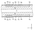
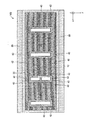
図1〜図4、及び図6に示すように、支持基板10の主部10Aの主面を覆う固体電解質膜(第1シール膜)40の表面(外側面)には(外縁部、並びに、各インターコネクタ30の外周の全周を取り囲む部分を除いた全ての領域)には、1つの連続した凹部(前記「第2凹部」に対応)が形成されている。これにより、この凹部は、固体電解質膜40の外側面における「各発電素子部Aに対応するそれぞれの領域を含んだ部分」に形成されている、と言える。
As shown in FIGS. 1 to 4 and 6, the surface (outer surface) of the solid electrolyte membrane (first seal film) 40 covering the main surface of the
図1〜図4、及び図6から理解できるように、この凹部は、固体電解質膜40の材料からなる底壁41と、支持基板10の主部10Aの主面を覆う固体電解質膜40の外縁部に位置するとともに固体電解質膜40の材料からなる側壁42と、各インターコネクタ30の外周の全周を取り囲む部分に位置するとともに固体電解質膜40の材料からなる側壁43と、で画定された窪みである。支持基板10の主部10Aの主面を外側(z軸方向)からみたとき、特に、図6から理解できるように、この凹部は、各インターコネクタ30が占める領域を除いた「固体電解質膜40の枠体で囲まれた大きな長方形状」を呈している。なお、図6は、支持基板10の主部10Aの主面に、固体電解質膜40及び後述する反応防止膜50が設けられ、且つ、後述する空気極60及び空気極集電膜70が設けられていない状態における支持基板10の平面図である。
As can be understood from FIG. 1 to FIG. 4 and FIG. 6, this recess has an outer edge of the
固体電解質膜(第1シール膜)40の表面(外側面)に形成された上記凹部には、反応防止膜50の全体(厚さ方向(z軸方向)における全域)が埋設(充填)されている。反応防止膜50は、緻密質材料からなる焼成体である。反応防止膜50の側壁の全周、及び、底壁の全面は、前記凹部内で固体電解質膜40と接触している。
In the concave portion formed on the surface (outer surface) of the solid electrolyte membrane (first seal membrane) 40, the entire reaction prevention membrane 50 (the entire region in the thickness direction (z-axis direction)) is embedded (filled). Yes. The
反応防止膜50は、例えば、GDC=(Ce,Gd)O2(ガドリニウム・ドープ・セリア)、及び、SDC=(Ce,Sm)O2(サマリウム・ドープ・セリア)等の希土類元素を含むセリアから構成され得る。反応防止膜50の厚さ(即ち、前記凹部の深さ)は、3〜50μmである。反応防止膜50は、凹部の底壁41上に配置され、凹部の側壁42,43に接触するように発電素子部Aの内部から発電素子部Aの外部へ延びている。反応防止膜50の全体(第1反応防止膜及び第2反応防止膜に対応)が、前記「第2シール膜」に対応する。
言い換えると、反応防止膜50の全体は、上記の発電素子部Aに含まれる反応防止膜50(第1反応防止膜)と、上記の発電素子部Aの外側における反応防止膜50(第2反応防止膜)とから、構成される。
The
In other words, the entire
図2〜図4に示すように、各インターコネクタ30の表面(外側面)と、固体電解質膜(第1シール膜)40の表面(外側面)と、反応防止膜(第2シール膜)50の表面(外側面)とにより、連続した1つの平面が構成されている。即ち、各インターコネクタ30の表面と固体電解質膜40の表面と反応防止膜50の表面との間で、段差が形成されていない。
As shown in FIGS. 2 to 4, the surface (outer surface) of each interconnector 30, the surface (outer surface) of the solid electrolyte membrane (first seal film) 40, and the reaction preventing film (second seal film) 50. A continuous plane is constituted by the surface (outer surface). That is, no step is formed between the surface of each interconnector 30, the surface of the
以上、支持基板10の主部10Aの表裏の各主面は、「インターコネクタ30と、固体電解質膜(第1シール膜)40と、反応防止膜(第2シール膜)50とからなる連続した緻密質膜」により覆われている。この連続した緻密質膜が前記「シール部」に対応する。各インターコネクタ30の表面と、固体電解質膜(第1シール膜)40の表面と、反応防止膜(第2シール膜)50の表面とにより、前記「シール部」の外側面が構成されている。
As described above, the main surfaces on the front and back of the
加えて、支持基板10の一対の側端部10B、10Bの表面は、側端部シール膜80、80という緻密質膜により覆われている。前記「シール部」、及び、側端部シール膜80、80によって形成される緻密質膜により、その緻密質膜の内側の空間を流れる燃料ガスと、その緻密質膜の外側の空間を流れる空気と、の混合が防止され得る。このガスシール機能を発揮するため、この緻密質膜(インターコネクタ30、固体電解質膜40、反応防止膜50、及び、側端部シール膜80)の気孔率は、10%以下である。
In addition, the surfaces of the pair of
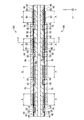
反応防止膜(第2シール膜)50における「支持基板10の主部10Aの主面を外側からみたときに燃料極活性部22に対応する部分」の上面には、空気極60が形成されている。空気極60は、電子伝導性を有する多孔質の材料からなる焼成体である。空気極60を上方からみた形状は、燃料極活性部22と略同一の長方形である。
An
空気極60は、例えば、LSCF=(La,Sr)(Co,Fe)O3(ランタンストロンチウムコバルトフェライト)から構成され得る。或いは、LSF=(La,Sr)FeO3(ランタンストロンチウムフェライト)、LNF=La(Ni,Fe)O3(ランタンニッケルフェライト)、LSC=(La,Sr)CoO3(ランタンストロンチウムコバルタイト)等から構成されてもよい。また、空気極60は、LSCFからなる第1層(内側層)とLSCからなる第2層(外側層)との2層によって構成されてもよい。空気極60の厚さは、10〜100μmである。
The
なお、固体電解質膜40と空気極60との間に反応防止膜50が介装されるのは、SOFC作製時又は作動中のSOFC内において固体電解質膜40内のYSZと空気極60内のSrとが反応して固体電解質膜40と空気極60との界面に電気抵抗が大きい反応層(SrZrO3)が形成される現象の発生を抑制するためである。
Note that the
ここで、燃料極20の燃料極活性部22と、固体電解質膜40における「支持基板10の主部10Aの主面を外側からみたときに燃料極活性部22に対応する部分(第1固体電解質膜に対応)」と、反応防止膜50における「支持基板10の主部10Aの主面を外側からみたときに燃料極活性部22に対応する部分(第1反応防止膜に対応)」と、空気極60とが積層されてなる積層体が、「発電素子部A」に対応する(図2、図3を参照)。即ち、支持基板10の主部10Aの上下面のそれぞれには、複数(本例では、4つ)の発電素子部Aが、長手方向において所定の間隔をおいて配置されている。
Here, the anode
図2、及び、図3に示すように、発電素子部Aの空気極60と、この発電素子部Aに隣り合うインターコネクタ30とを跨ぐように、空気極60、反応防止膜50、固体電解質膜40、及び、インターコネクタ30の表面(外側面)に、空気極集電膜70が形成されている。空気極集電膜70は、電子伝導性を有する多孔質の材料からなる焼成体である。空気極集電膜70を外側からみた形状は、長方形である。
As shown in FIGS. 2 and 3, the
空気極集電膜70は、例えば、LSCF=(La,Sr)(Co,Fe)O3(ランタンストロンチウムコバルトフェライト)から構成され得る。或いは、LSC=(La,Sr)CoO3(ランタンストロンチウムコバルタイト)から構成されてもよい。或いは、Ag(銀)、Ag−Pd(銀パラジウム合金)から構成されてもよい。或いは、La(Ni、Fe、Cu)O3で構成されてもよい。即ち、空気極集電膜70は、ストロンチウム(Sr)又はランタン(La)を含む。空気極集電膜70の厚さは、50〜500μmである。
The air electrode
このように各空気極集電膜70が形成されることにより、各組の隣り合う発電素子部A,Aについて、一方の発電素子部Aの空気極60と、他方の発電素子部Aの燃料極20(特に、燃料極集電部21)とが、電子伝導性を有する「空気極集電膜70及びインターコネクタ30」を介して電気的に接続される。この結果、支持基板10の主部10Aの上下面のそれぞれに配置されている複数(本例では、4つ)の発電素子部Aが電気的に直列に接続される。ここで、電子伝導性を有する「空気極集電膜70及びインターコネクタ30」が、前記「電気的接続部」に対応する。
By forming each air electrode
なお、インターコネクタ30は、前記「電気的接続部」における前記「緻密質材料で構成された第1部分」に対応し、気孔率は10%以下である。空気極集電膜70は、前記「電気的接続部」における前記「多孔質の材料で構成された第2部分」に対応し、気孔率は20〜60%である。
The
以上、説明した「横縞型」のSOFC100に対して、図7に示すように、支持基板10の燃料ガス流路11内に燃料ガス(水素ガス等)を流すとともに、支持基板10の上下面(特に、各空気極集電膜70)を「酸素を含むガス」(空気等)に曝す(或いは、支持基板10の上下面に沿って酸素を含むガスを流す)ことにより、固体電解質膜40の両側面間に生じる酸素分圧差によって起電力が発生する。更に、このSOFC100を外部の負荷に接続すると、下記(1)、(2)式に示す化学反応が起こり、電流が流れる(発電状態)。
(1/2)・O2+2e−→O2− (於:空気極60) …(1)
H2+O2−→H2O+2e− (於:燃料極20) …(2)
As described above, as shown in FIG. 7, the fuel gas (hydrogen gas or the like) flows through the fuel
(1/2) · O 2 + 2e− → O 2− (where: air electrode 60) (1)
H 2 + O 2− → H 2 O + 2e − (in the fuel electrode 20) (2)
発電状態においては、図8及び図9に示すように、各組の隣り合う発電素子部A,Aについて、電流が、矢印で示すように流れる。この結果、図7に示すように、SOFC100全体から(具体的には、図7において最も手前側の発電素子部Aのインターコネクタ30と最も奥側の発電素子部Aの空気極60とを介して)電力が取り出される。
In the power generation state, as shown in FIGS. 8 and 9, a current flows as indicated by an arrow in each pair of adjacent power generation element portions A and A. As a result, as shown in FIG. 7, from the entire SOFC 100 (specifically, via the
(本実施形態の製造方法)
次に、図1に示したSOFC100の製造方法の一例について図10〜図18を参照しながら簡単に説明する。図10〜図18において、各部材の符号の末尾の「g」は、その部材が「焼成前」であることを表す。
(Manufacturing method of this embodiment)
Next, an example of a method for manufacturing the
先ず、図10に示す形状を有する支持基板の成形体10gが作製される。この支持基板の成形体10gは、例えば、支持基板10の材料(例えば、CSZ)の粉末にバインダー等が添加されて得られるスラリーを用いて、押し出し成形、切削等の手法を利用して作製され得る。以下、図10に示す11−11線に対応する部分断面を表す図11〜図18を参照しながら説明を続ける。
First, a support substrate molded
図11に示すように、支持基板の成形体10gが作製されると、次に、図12に示すように、支持基板の成形体10gの上下面に形成された各凹部12に、燃料極集電部の成形体21gがそれぞれ埋設・形成される。次いで、図13に示すように、各燃料極集電部の成形体21gの外側面に形成された各凹部に、燃料極活性部の成形体22gの全体がそれぞれ埋設・形成される。各燃料極集電部の成形体21g、及び各燃料極活性部22gは、例えば、燃料極20の材料(例えば、NiとYSZ)の粉末にバインダー等が添加されて得られるスラリーを用いて、印刷法等を利用して埋設・形成される。
As shown in FIG. 11, when the support substrate molded
続いて、図14に示すように、各燃料極集電部の成形体21gの外側面における「燃料極活性部の成形体22gが埋設された部分を除いた部分」に形成された各凹部に、インターコネクタの成形体30gの一部(内側の半分)がそれぞれ埋設・形成される。各インターコネクタの成形体30gは、例えば、インターコネクタ30の材料(例えば、LaCrO3)の粉末にバインダー等が添加されて得られるスラリーを用いて、印刷法等を利用して埋設・形成される。
Subsequently, as shown in FIG. 14, in each recess formed in “the portion excluding the portion where the molded
次に、図15に示すように、複数の燃料極の成形体(21g+22g)及び複数のインターコネクタの成形体30gがそれぞれ埋設・形成された状態の支持基板の成形体10gにおける主部10Aの主面(即ち、上下の主面)において複数のインターコネクタの成形体30gが形成されたそれぞれの部分を除いた全面に、固体電解質膜の成形体40gが形成される。固体電解質膜の成形体40gは、例えば、固体電解質膜40の材料(例えば、YSZ)の粉末にバインダー等が添加されて得られるスラリーを用いて、印刷法、ディッピング法等を利用して形成される。
Next, as shown in FIG. 15, the
加えて、支持基板の成形体10gの一対の側端部10B、10Bの表面の全面に、側端部シール部の成形体がそれぞれ形成される。このとき、支持基板の成形体10gの段差STの近傍部分において、側端部シール部の成形体の縁部と固体電解質膜の成形体40gの縁部とが厚さ方向に重なるように(オーバラップするように)、側端部シール部の成形体が形成される。側端部シール部の成形膜も、例えば、固体電解質膜40の材料(例えば、YSZ)の粉末にバインダー等が添加されて得られるスラリーを用いて、印刷法、ディッピング法等を利用して形成される。
In addition, a molded body of the side end seal portion is formed on the entire surface of the pair of
次に、図16に示すように、固体電解質膜の成形体40gの外側面に形成された凹部に、反応防止膜の成形体50gがそれぞれ形成される。各反応防止膜の成形体50gは、例えば、反応防止膜50の材料(例えば、GDC)の粉末にバインダー等が添加されて得られるスラリーを用いて、印刷法等を利用して形成される。
Next, as shown in FIG. 16, reaction prevention molded
そして、このように種々の成形体が形成された状態の支持基板の成形体10gが、空気中にて1500℃で3時間焼成される。これにより、図1に示したSOFCにおいて空気極60、及び、空気極集電膜70が形成されていない状態の構造体(上述した「中間焼成体」に対応)が得られる。
Then, 10 g of the support substrate molded body in which various molded bodies are formed in this manner is fired in air at 1500 ° C. for 3 hours. Thereby, a structure (corresponding to the “intermediate fired body” described above) in which the
次に、図17に示すように、「中間焼成体」における反応防止膜50の外側面に、空気極の成形体60gが形成される。各空気極の成形体60gは、例えば、空気極60の材料(例えば、LSCF)の粉末にバインダー等が添加されて得られるスラリーを用いて、印刷法等を利用して形成される。
Next, as shown in FIG. 17, an air electrode molded
次に、図18に示すように、各組の隣り合う発電素子部について、一方の発電素子部の空気極の成形膜60gと、他方の発電素子部のインターコネクタ30とを跨ぐように、空気極の成形膜60g、反応防止膜50、固体電解質膜40、及び、インターコネクタ30の外側面に、空気極集電膜の成形膜70gが形成される。各空気極集電膜の成形膜70gは、例えば、空気極集電膜70の材料(例えば、LSCF、La(Ni、Fe、Cu)O3)の粉末にバインダー等が添加されて得られるスラリーを用いて、印刷法等を利用して形成される。
Next, as shown in FIG. 18, for each pair of adjacent power generation element portions, air is formed so as to straddle the air
そして、このように成形膜60g、70gが形成された状態の支持基板10が、空気中にて1050℃で3時間焼成される。これにより、図1に示したSOFC100が得られる。以上、図1に示したSOFCの製造方法の一例について説明した。
Then, the
なお、この時点では、酸素含有雰囲気での焼成により、支持基板10、及び燃料極20中のNi成分が、NiOとなっている。従って、燃料極20の導電性を獲得するため、その後、支持基板10側から還元性の燃料ガスが流され、NiOが800〜1000℃で1〜10時間に亘って還元処理される。なお、この還元処理は発電時に行われてもよい。
At this time, the Ni component in the
(本実施形態の作用・効果)
以上、説明したように、上記本実施形態では、固体電解質膜(第1シール膜)40の表面(外側面)に形成された凹部(前記「第2凹部」)に、反応防止膜(第2シール膜)50の全体(厚さ方向(z軸方向)の全域)が埋設されている。換言すれば、「中間焼成体」の外側面における反応防止膜(第2シール膜)50の外縁にて段差が形成されていない。従って、上述した「背景技術」の欄で取り上げた文献に記載された燃料電池の構成(即ち、反応防止膜における厚さ方向の全域が固体電解質膜の外側面に対して厚さ方向に突出している構成)と比べて、「中間焼成体」の外側面における反応防止膜50の外縁にて形成される段差の高さが小さくなる。この結果、反応防止膜50の外縁の近傍部分にて過大な応力が局所的に発生し難くなり、前記外縁の近傍部分にてクラックが発生し難くなる。
(Operation and effect of this embodiment)
As described above, in the present embodiment, the reaction preventing film (the second concave portion) is formed in the concave portion (the “second concave portion”) formed on the surface (outer surface) of the solid electrolyte membrane (first sealing film) 40. The entire seal film 50 (the entire region in the thickness direction (z-axis direction)) is embedded. In other words, no step is formed at the outer edge of the reaction preventing film (second seal film) 50 on the outer surface of the “intermediate fired body”. Accordingly, the structure of the fuel cell described in the literature taken up in the above-mentioned “Background Art” section (that is, the entire region in the thickness direction of the reaction preventing film protrudes in the thickness direction with respect to the outer surface of the solid electrolyte membrane). The height of the step formed on the outer edge of the
なお、前記「第2凹部」に、反応防止膜50における厚さ方向の一部のみが埋設される場合(即ち、反応防止膜50における厚さ方向の内側部分が「第2凹部」に埋設され、反応防止膜50における厚さ方向の外側部分が固体電解質膜40の外側面に対して厚さ方向に突出している場合)においても、上述した文献に記載された燃料電池の構成と比べて、「中間焼成体」の外側面における反応防止膜50の外縁にて形成される段差の高さが小さくなる。従って、この場合であっても、上記本実施形態と同様、上述した文献に記載された燃料電池の構成と比べて、反応防止膜50の外縁の近傍部分にて過大な応力が局所的に発生し難くなり、前記外縁の近傍部分にてクラックが発生し難くなる。
When only a part of the
また、上記本実施形態では、前記「第2凹部」は、固体電解質膜40の材料からなる底壁41と、全周に亘って固体電解質膜40の材料からなる周方向に閉じた側壁42及び側壁43と、を有する。換言すれば、前記「第2凹部」に埋設された反応防止膜50の側面の全周が、固体電解質膜40で構成される枠体で確実に覆われている。
In the present embodiment, the “second recess” includes the
本実施形態では、前記「シール部」で区画される内側領域が還元雰囲気になり、前記「「シール部」で区画される外側領域が酸化雰囲気になる。ここで、反応防止膜50は、「セリアを含んだ材料」(例えば、ガドリニウム・ドープ・セリア(GDC))で構成されている。一般に、「セリアを含んだ材料」は、還元雰囲気に曝されると、膨張し易い。従って、反応防止膜50を還元雰囲気に曝すと、自身の膨張に起因して、反応防止膜50の剥離、及び反り等が発生し易い。この点、上記本実施形態では、上述のように、反応防止膜50の側面の全周が、固体電解質膜40で構成される枠体で確実に覆われている。従って、反応防止膜50が、前記「シール部」(より具体的には、固体電解質膜40)の内側領域の雰囲気(即ち、還元雰囲気)に曝され難くなる。この結果、上述した「反応防止膜50の剥離、及び反り等」が発生し難くなる。
In the present embodiment, the inner area defined by the “seal part” is a reducing atmosphere, and the outer area defined by the ““ seal part ”is an oxidizing atmosphere. Here, the
また、支持基板10の主部10Aと一対の側端部10B、10Bとの表裏の境界部にはそれぞれ、側端部10B側が主部10A側に対して厚さ方向に突出する長手方向に延びる一対の段差ST、STが形成されている(図10を参照)。加えて、支持基板10の段差STの近傍部分において、側端部シール部80の縁部と固体電解質膜(第1シール膜)40の縁部とが厚さ方向に重なるように(オーバラップするように)、側端部シール部80が固体電解質膜40と接続されている。
Further, the front and back boundary portions of the
この結果、「固体電解質膜と側端部シール部とが繋ぎ目なく(シームレスに)繋がった」従来の構成と比べて、固体電解質膜40と側端部シール部80との接続部の周辺にてクラックが発生し難くなることが判明した。これは、詳細は不明であるが、上記本実施形態では、上記従来の構成と比べて、固体電解質膜40と側端部シール部80との接続部の周辺にて局所的に過大な熱応力が発生し難くなることに起因する、と考えられる。
As a result, compared to the conventional configuration in which “the solid electrolyte membrane and the side end seal portion are seamlessly connected”, in the vicinity of the connection portion between the
なお、本発明は上記本実施形態に限定されることはなく、本発明の範囲内において種々の変形例を採用することができる。例えば、上記本実施形態では、固体電解質膜(第1シール膜)40とインターコネクタ30とが直接接触しているが(図2、図3、図5、及び、図6を参照)、図2、図3、図5、及び、図6にそれぞれ対応する図19、図20、図21、及び、図22に示すように、固体電解質膜(第1シール膜)40とインターコネクタ30とが、インターコネクタ30の周縁部の全周に亘って形成された「固体電解質膜(第1シール膜)40、反応防止膜(第2シール膜)50、及びインターコネクタ30とは異なる緻密質材料からなるシール部35」(前記「第3シール部」に対応)を介して接続されてもよい。この場合、固体電解質膜(第1シール膜)40とインターコネクタ30とは接触しない。なお、この例でも、上記本実施形態と同様、前記「第2凹部」が、固体電解質膜40の材料からなる底壁41と、全周に亘って固体電解質膜40の材料からなる周方向に閉じた側壁42及び側壁43と、を有している。
The present invention is not limited to the above-described embodiment, and various modifications can be employed within the scope of the present invention. For example, in the present embodiment, the solid electrolyte membrane (first seal membrane) 40 and the
図19、図20、図21、及び、図22に示す例では、前記「シール部」は、「各インターコネクタ30と、各シール部(第3シール部)35と、固体電解質膜(第1シール膜)40と、反応防止膜(第2シール膜)50からなる連続した緻密質膜」に対応する。この場合、各インターコネクタ30の表面と、各シール部35の表面と、固体電解質膜(第1シール膜)40の表面と、反応防止膜(第2シール膜)50の表面と、により、前記「シール部」の外側面が構成される。
In the example shown in FIGS. 19, 20, 21, and 22, the “seal portion” includes “each interconnector 30, each seal portion (third seal portion) 35, and solid electrolyte membrane (first This corresponds to a continuous dense film composed of a sealing
この例では、各インターコネクタ30の表面(外側面)と、各シール部35の表面(外側面)と、固体電解質膜(第1シール膜)40の表面(外側面)と、反応防止膜(第2シール膜)50の表面(外側面)とにより、連続した1つの平面が構成されている。即ち、各インターコネクタ30の表面と各シール部35の表面と固体電解質膜40の表面と反応防止膜50の表面との間で、段差が形成されていない。
In this example, the surface (outer surface) of each interconnector 30, the surface (outer surface) of each
一般に、インターコネクタ30は、ランタンクロマイトで構成され、固体電解質膜40は、イットリア安定化ジルコニアで構成され得る。ここで、ランタンクロマイトがジルコニアと接触すると、ランタンクロマイトが脆くなってランタンクロマイトの緻密性が失われ易い。この点、図19、図20、図21、及び、図22に示す例では、シール部35の導入によって、固体電解質膜40とインターコネクタ30とが接触しない。この結果、インターコネクタ30と固体電解質膜30との接触に起因してインターコネクタ30の緻密性が失われる、という問題が発生し難くなる。
In general, the
また、上記本実施形態では、前記「第2凹部」は、固体電解質膜40の材料からなる底壁41と、全周に亘って固体電解質膜40の材料からなる周方向に閉じた側壁42及び側壁43と、を有する。換言すれば、前記「第2凹部」に埋設された反応防止膜50の側面の全周が、固体電解質膜40で構成される枠体で確実に覆われている。これに対し、前記「第2凹部」の側壁が、「全周に亘って固体電解質膜40の材料からなる周方向に閉じた側壁」でなくてもよい。換言すれば、前記「第2凹部」に埋設された反応防止膜50の側面の全周が、固体電解質膜40で構成される枠体で覆われていなくてもよい。
In the present embodiment, the “second recess” includes the
また、上記本実施形態では、平板状の支持基板10の上下面のそれぞれに複数の凹部12が形成され且つ複数の発電素子部Aが設けられているが、支持基板10の片側面のみに複数の凹部12が形成され且つ複数の発電素子部Aが設けられていてもよい。また、この場合、支持基板が円筒状であってもよい。支持基板が円筒状の場合、円筒状の支持基板の内部空間が前記「ガス流路」に対応し得る。
Further, in the present embodiment, a plurality of
10…支持基板、10A…主部、10B…側端部、11…燃料ガス流路、12…凹部、20…燃料極、21…燃料極集電部、21a、21b…凹部、22…燃料極活性部、30…インターコネクタ、35…シール部(第3シール部)、40…固体電解質膜(第1シール膜)、50…反応防止膜(第2シール膜)、60…空気極、70…空気極集電膜、80…側端部シール部、A…発電素子部、ST…段差
DESCRIPTION OF
Claims (9)
前記支持基板の主面における互いに離れた複数の箇所にそれぞれ設けられ、少なくとも燃料極、緻密質材料からなる固体電解質膜、希土類元素を含むセリアを含んだ緻密質材料からなる反応防止膜、及び、空気極がこの順に積層された複数の発電素子部と、
隣り合う前記発電素子部の一方の燃料極と他方の空気極とを電気的に接続する1つ又は複数の電気的接続部と、
前記支持基板の主面を覆うように設けられ、前記ガス流路を経て前記燃料極に供給されるガスと、前記空気極に供給されるガスと、の混合を防止する、緻密質材料からなるシール部と、
を備えた、焼成体である燃料電池であって、
前記各電気的接続部は、緻密質材料からなる第1部分と、前記第1部分と接続され且つ多孔質材料からなる第2部分とで構成され、前記第1部分は、前記隣り合う発電素子部の一方の燃料極と前記第2部分とに接続され、前記第2部分は、前記隣り合う発電素子部の他方の空気極と前記第1部分とに接続され、
前記支持基板の主面における前記複数の箇所に、前記支持基板の材料からなる底壁と、全周に亘って前記支持基板の材料からなる周方向に閉じた側壁と、を有する第1凹部がそれぞれ形成され、
前記各第1凹部に、対応する前記発電素子部の前記燃料極がそれぞれ埋設され、
前記シール部は、前記各電気的接続部のそれぞれの第1部分と、前記各発電素子部に含まれるそれぞれの前記固体電解質膜を含むとともに前記それぞれの前記固体電解質膜から連続して延設された前記固体電解質と同じ緻密質材料からなる第1シール膜と、前記各発電素子部に含まれるそれぞれの前記反応防止膜を含むとともに前記それぞれの前記反応防止膜から連続して延設された前記反応防止膜と同じ緻密質材料からなる第2シール膜と、を含んで構成され、
前記第1シール膜の外側面における前記各発電素子部に対応するそれぞれの領域を含んだ部分に、前記第1シール膜の材料からなる底壁と、前記第1シール膜の材料からなる側壁と、を有する第2凹部が形成され、
前記第2凹部に、前記第2シール膜が埋設され、
前記各電気的接続部のそれぞれの第1部分の外側面と、前記第1シール膜の外側面における前記第2凹部以外の部分と、前記第2凹部に埋設された前記第2シール膜の外側面と、を含んで、前記シール部の外側面が構成され、
前記第2凹部は、前記第1シール膜の材料からなる底壁と、全周に亘って前記第1シール膜の材料からなる周方向に閉じた側壁と、を有する、
燃料電池。 A support substrate having a longitudinal direction, wherein the gas flow path is formed inside along the longitudinal direction;
Provided respectively at a plurality of locations separated from each other on the main surface of the support substrate, at least a fuel electrode, a solid electrolyte film made of a dense material, a reaction preventing film made of a dense material containing ceria containing a rare earth element, and A plurality of power generation element units in which air electrodes are stacked in this order;
One or a plurality of electrical connection portions that electrically connect one fuel electrode and the other air electrode of the adjacent power generation element portions;
It is provided so as to cover the main surface of the support substrate, and is made of a dense material that prevents mixing of the gas supplied to the fuel electrode via the gas flow path and the gas supplied to the air electrode. A seal part;
A fuel cell comprising a fired body, comprising:
Each of the electrical connection portions includes a first portion made of a dense material and a second portion connected to the first portion and made of a porous material, and the first portion is the adjacent power generation element. Connected to one fuel electrode of the part and the second part, the second part is connected to the other air electrode of the adjacent power generation element part and the first part,
A first recess having a bottom wall made of the material of the support substrate and a side wall closed in the circumferential direction made of the material of the support substrate over the entire circumference at the plurality of locations on the main surface of the support substrate. Each formed,
In each of the first recesses, the corresponding fuel electrode of the power generation element unit is embedded,
The seal portion includes a first portion of each electrical connection portion and each solid electrolyte membrane included in each power generation element portion, and extends continuously from each solid electrolyte membrane. In addition, the first seal film made of the same dense material as the solid electrolyte and the respective reaction prevention films included in each of the power generation element portions, and continuously extending from the respective reaction prevention films A second sealing film made of the same dense material as the reaction preventing film,
A portion of the outer surface of the first seal film including a region corresponding to each power generating element portion includes a bottom wall made of the material of the first seal film, and a side wall made of the material of the first seal film. A second recess having
The second sealing film is embedded in the second recess,
The outer surface of the first portion of each electrical connection portion, the portion other than the second recess on the outer surface of the first seal film, and the outside of the second seal film embedded in the second recess. A side surface, and an outer surface of the seal portion is configured,
The second recess has a bottom wall made of the material of the first seal film and a side wall closed in the circumferential direction made of the material of the first seal film over the entire circumference.
Fuel cell.
請求項1に記載の燃料電池。 The outer surface of the first portion of each electrical connection portion, the portion other than the second recess on the outer surface of the first seal film, and the outside of the second seal film embedded in the second recess. A side surface and a continuous outer surface of the seal portion are configured.
The fuel cell according to claim 1.
前記第1シール膜と前記各電気的接続部の第1部分とは接触しないように構成され、
前記各電気的接続部のそれぞれの第1部分の外側面と、前記第1シール膜の外側面における前記第2凹部以外の部分と、前記第2凹部に埋設された前記第2シール膜の外側面と、前記各第3シール部のそれぞれの外側面と、により、前記シール部の外側面が構成される、
請求項1に記載の燃料電池。 The seal part includes a plurality of third seal parts made of a dense material that is connected to the first part of each electrical connection part and the first seal film and is different from the first and second seal films,
The first seal film and the first portion of each electrical connection portion are configured not to contact each other,
The outer surface of the first portion of each electrical connection portion, the portion other than the second recess on the outer surface of the first seal film, and the outside of the second seal film embedded in the second recess. The outer surface of the seal portion is configured by the side surface and the outer surface of each of the third seal portions.
The fuel cell according to claim 1.
請求項3に記載の燃料電池。 The outer surface of the first portion of each electrical connection portion, the portion other than the second recess on the outer surface of the first seal film, and the outside of the second seal film embedded in the second recess. A continuous outer surface of the seal portion is constituted by the side surface and the outer surface of each of the third seal portions.
The fuel cell according to claim 3.
前記支持基板の主面において前記長手方向に互いに間隔を隔てて設けられ、燃料極、第1固体電解質膜、第1反応防止膜、及び空気極が、この順に積層された複数の発電素子部と、
隣り合う前記発電素子部の一方の燃料極と他方の空気極とを電気的に接続する電気的接続部と、
前記ガス流路から前記燃料極に供給されるガスと、前記空気極に供給されるガスとの混合を防止するために、前記支持基板の主面に設けられるシール部と、
を備え、
前記支持基板は、前記燃料極が配置される第1凹部を、有し、
前記各電気的接続部は、前記隣り合う発電素子部の一方の燃料極に接続される第1部分と、前記隣り合う発電素子部の他方の空気極に接続される第2部分とから、構成され、
前記シール部は、
前記各電気的接続部の前記第1部分と、
前記第1固体電解質膜、及び前記第1固体電解質膜から連続して延びる第2固体電解質膜を含み、且つ周方向に側壁が閉じた第2凹部が外側面に形成される第1シール膜と、
前記第1反応防止膜、及び前記第1反応防止膜から連続して延びる第2反応防止膜を含み、且つ前記第2凹部に配置される第2シール膜とから、構成され、
前記シール部の外側面は、
前記各電気的接続部における前記第1部分の外側面と、
前記第1シール膜の外側面において前記第2凹部を除いた部分と、
前記第2シール膜の外側面とから、構成される、
燃料電池。 A support substrate having a gas flow path formed therein along the longitudinal direction;
A plurality of power generation element portions provided on the main surface of the support substrate at intervals in the longitudinal direction, wherein a fuel electrode, a first solid electrolyte membrane, a first reaction preventing film, and an air electrode are stacked in this order; ,
An electrical connection part that electrically connects one fuel electrode and the other air electrode of the adjacent power generation element part;
In order to prevent mixing of the gas supplied from the gas flow path to the fuel electrode and the gas supplied to the air electrode, a seal portion provided on the main surface of the support substrate;
With
The support substrate has a first recess in which the fuel electrode is disposed,
Each of the electrical connection portions includes a first portion connected to one fuel electrode of the adjacent power generation element portion and a second portion connected to the other air electrode of the adjacent power generation element portion. And
The seal portion is
The first portion of each electrical connection;
A first seal membrane including the first solid electrolyte membrane and a second solid electrolyte membrane extending continuously from the first solid electrolyte membrane, and a second recess having a side wall closed in the circumferential direction is formed on an outer surface; ,
The first reaction preventing film, and a second seal film including the second reaction preventing film continuously extending from the first reaction preventing film and disposed in the second recess,
The outer surface of the seal portion is
An outer surface of the first portion in each electrical connection;
A portion of the outer surface of the first sealing film excluding the second recess;
The outer surface of the second seal film,
Fuel cell.
請求項5に記載の燃料電池。 The first seal film and the second seal film are disposed between the fuel electrode and the air electrode.
The fuel cell according to claim 5.
請求項5又は6に記載の燃料電池。 The outer surface of the first portion in each electrical connection portion, the portion of the outer surface of the first seal film excluding the second recess, and the outer surface of the second seal film are configured continuously. Being
The fuel cell according to claim 5 or 6.
前記シール部の外側面は、
前記各電気的接続部における前記第1部分の外側面と、
前記第1シール膜の外側面において前記第2凹部を除いた部分と、
前記第2シール膜の外側面と、
前記第3シール部の外側面とから、構成される、
請求項5又は6に記載の燃料電池。 The seal portion is disposed between the first portion of each electrical connection portion and the first seal film, and is connected to the first portion and the first seal membrane of each electrical connection portion. 3 seals further,
The outer surface of the seal portion is
An outer surface of the first portion in each electrical connection;
A portion of the outer surface of the first sealing film excluding the second recess;
An outer surface of the second sealing film;
The outer surface of the third seal portion is configured,
The fuel cell according to claim 5 or 6.
請求項8に記載の燃料電池。 The outer surface of the first portion in each of the electrical connection portions, the portion of the outer surface of the first seal film except the second recess, the outer surface of the second seal film, and the third seal portion The outer surface of the is configured continuously,
The fuel cell according to claim 8.
Priority Applications (1)
| Application Number | Priority Date | Filing Date | Title |
|---|---|---|---|
| JP2016000149A JP5895112B1 (en) | 2015-01-07 | 2016-01-04 | Fuel cell |
Applications Claiming Priority (3)
| Application Number | Priority Date | Filing Date | Title |
|---|---|---|---|
| JP2015001258 | 2015-01-07 | ||
| JP2015001258 | 2015-01-07 | ||
| JP2016000149A JP5895112B1 (en) | 2015-01-07 | 2016-01-04 | Fuel cell |
Publications (2)
| Publication Number | Publication Date |
|---|---|
| JP5895112B1 true JP5895112B1 (en) | 2016-03-30 |
| JP2016131146A JP2016131146A (en) | 2016-07-21 |
Family
ID=55628575
Family Applications (1)
| Application Number | Title | Priority Date | Filing Date |
|---|---|---|---|
| JP2016000149A Expired - Fee Related JP5895112B1 (en) | 2015-01-07 | 2016-01-04 | Fuel cell |
Country Status (1)
| Country | Link |
|---|---|
| JP (1) | JP5895112B1 (en) |
Families Citing this family (1)
| Publication number | Priority date | Publication date | Assignee | Title |
|---|---|---|---|---|
| JP6979509B1 (en) * | 2020-12-28 | 2021-12-15 | 三菱パワー株式会社 | Manufacturing method of fuel cell, fuel cell cartridge, and fuel cell |
Citations (2)
| Publication number | Priority date | Publication date | Assignee | Title |
|---|---|---|---|---|
| JP4828663B1 (en) * | 2010-07-15 | 2011-11-30 | 日本碍子株式会社 | Fuel cell structure |
| JP2014225436A (en) * | 2013-04-19 | 2014-12-04 | 日本碍子株式会社 | Fuel cell |
-
2016
- 2016-01-04 JP JP2016000149A patent/JP5895112B1/en not_active Expired - Fee Related
Patent Citations (2)
| Publication number | Priority date | Publication date | Assignee | Title |
|---|---|---|---|---|
| JP4828663B1 (en) * | 2010-07-15 | 2011-11-30 | 日本碍子株式会社 | Fuel cell structure |
| JP2014225436A (en) * | 2013-04-19 | 2014-12-04 | 日本碍子株式会社 | Fuel cell |
Also Published As
| Publication number | Publication date |
|---|---|
| JP2016131146A (en) | 2016-07-21 |
Similar Documents
| Publication | Publication Date | Title |
|---|---|---|
| JP4850980B1 (en) | Fuel cell structure | |
| JP5417516B1 (en) | Fuel cell | |
| JP6169930B2 (en) | Solid oxide fuel cell | |
| JP5646780B2 (en) | Fuel cell | |
| JP5752287B1 (en) | Fuel cell | |
| JP5600819B1 (en) | Fuel cell | |
| JP4824137B1 (en) | Fuel cell structure | |
| JP5443648B1 (en) | Fuel cell structure | |
| JP5642855B1 (en) | Fuel cell | |
| JP6039459B2 (en) | Solid oxide fuel cell | |
| JP5485444B1 (en) | Fuel cell | |
| JP5075268B1 (en) | Fuel cell structure | |
| JP5826963B1 (en) | Fuel cell | |
| JP5895112B1 (en) | Fuel cell | |
| JP5613808B1 (en) | Fuel cell | |
| JP5727062B1 (en) | Fuel cell | |
| JP5895113B1 (en) | Fuel cell | |
| JP5646785B1 (en) | Fuel cell | |
| JP5752297B1 (en) | Fuel cell | |
| JP5062786B1 (en) | Fuel cell structure | |
| JP7270703B2 (en) | cell | |
| JP4824136B1 (en) | Fuel cell structure | |
| JP5587479B1 (en) | Fuel cell | |
| JP5753930B1 (en) | Fuel cell | |
| JP5621029B1 (en) | Fuel cell |
Legal Events
| Date | Code | Title | Description |
|---|---|---|---|
| A621 | Written request for application examination |
Free format text: JAPANESE INTERMEDIATE CODE: A621 Effective date: 20160104 |
|
| A871 | Explanation of circumstances concerning accelerated examination |
Free format text: JAPANESE INTERMEDIATE CODE: A871 Effective date: 20160104 |
|
| A975 | Report on accelerated examination |
Free format text: JAPANESE INTERMEDIATE CODE: A971005 Effective date: 20160126 |
|
| TRDD | Decision of grant or rejection written | ||
| A01 | Written decision to grant a patent or to grant a registration (utility model) |
Free format text: JAPANESE INTERMEDIATE CODE: A01 Effective date: 20160209 |
|
| A61 | First payment of annual fees (during grant procedure) |
Free format text: JAPANESE INTERMEDIATE CODE: A61 Effective date: 20160229 |
|
| R150 | Certificate of patent or registration of utility model |
Ref document number: 5895112 Country of ref document: JP Free format text: JAPANESE INTERMEDIATE CODE: R150 |
|
| LAPS | Cancellation because of no payment of annual fees |