JP5895065B2 - UPLINK TRANSMISSION POWER CONTROL METHOD AND USER DEVICE - Google Patents
UPLINK TRANSMISSION POWER CONTROL METHOD AND USER DEVICE Download PDFInfo
- Publication number
- JP5895065B2 JP5895065B2 JP2014547689A JP2014547689A JP5895065B2 JP 5895065 B2 JP5895065 B2 JP 5895065B2 JP 2014547689 A JP2014547689 A JP 2014547689A JP 2014547689 A JP2014547689 A JP 2014547689A JP 5895065 B2 JP5895065 B2 JP 5895065B2
- Authority
- JP
- Japan
- Prior art keywords
- carrier
- carriers
- transmission power
- uplink
- channel
- Prior art date
- Legal status (The legal status is an assumption and is not a legal conclusion. Google has not performed a legal analysis and makes no representation as to the accuracy of the status listed.)
- Active
Links
- 230000005540 biological transmission Effects 0.000 title claims description 123
- 238000000034 method Methods 0.000 title claims description 33
- 239000000969 carrier Substances 0.000 claims description 82
- 238000010586 diagram Methods 0.000 description 5
- 239000002699 waste material Substances 0.000 description 4
- 101000741965 Homo sapiens Inactive tyrosine-protein kinase PRAG1 Proteins 0.000 description 1
- 102100038659 Inactive tyrosine-protein kinase PRAG1 Human genes 0.000 description 1
- 238000004891 communication Methods 0.000 description 1
- 238000005516 engineering process Methods 0.000 description 1
- 230000007774 longterm Effects 0.000 description 1
- 238000012986 modification Methods 0.000 description 1
- 230000004048 modification Effects 0.000 description 1
- 230000003287 optical effect Effects 0.000 description 1
Images


Classifications
-
- H—ELECTRICITY
- H04—ELECTRIC COMMUNICATION TECHNIQUE
- H04W—WIRELESS COMMUNICATION NETWORKS
- H04W52/00—Power management, e.g. TPC [Transmission Power Control], power saving or power classes
- H04W52/04—TPC
- H04W52/30—TPC using constraints in the total amount of available transmission power
-
- H—ELECTRICITY
- H04—ELECTRIC COMMUNICATION TECHNIQUE
- H04W—WIRELESS COMMUNICATION NETWORKS
- H04W52/00—Power management, e.g. TPC [Transmission Power Control], power saving or power classes
- H04W52/04—TPC
- H04W52/30—TPC using constraints in the total amount of available transmission power
- H04W52/36—TPC using constraints in the total amount of available transmission power with a discrete range or set of values, e.g. step size, ramping or offsets
- H04W52/367—Power values between minimum and maximum limits, e.g. dynamic range
-
- H—ELECTRICITY
- H04—ELECTRIC COMMUNICATION TECHNIQUE
- H04W—WIRELESS COMMUNICATION NETWORKS
- H04W52/00—Power management, e.g. TPC [Transmission Power Control], power saving or power classes
- H04W52/04—TPC
- H04W52/06—TPC algorithms
- H04W52/14—Separate analysis of uplink or downlink
- H04W52/146—Uplink power control
-
- H—ELECTRICITY
- H04—ELECTRIC COMMUNICATION TECHNIQUE
- H04W—WIRELESS COMMUNICATION NETWORKS
- H04W52/00—Power management, e.g. TPC [Transmission Power Control], power saving or power classes
- H04W52/04—TPC
- H04W52/18—TPC being performed according to specific parameters
- H04W52/24—TPC being performed according to specific parameters using SIR [Signal to Interference Ratio] or other wireless path parameters
- H04W52/241—TPC being performed according to specific parameters using SIR [Signal to Interference Ratio] or other wireless path parameters taking into account channel quality metrics, e.g. SIR, SNR, CIR, Eb/lo
-
- H—ELECTRICITY
- H04—ELECTRIC COMMUNICATION TECHNIQUE
- H04W—WIRELESS COMMUNICATION NETWORKS
- H04W52/00—Power management, e.g. TPC [Transmission Power Control], power saving or power classes
- H04W52/04—TPC
- H04W52/18—TPC being performed according to specific parameters
- H04W52/26—TPC being performed according to specific parameters using transmission rate or quality of service QoS [Quality of Service]
- H04W52/267—TPC being performed according to specific parameters using transmission rate or quality of service QoS [Quality of Service] taking into account the information rate
-
- H—ELECTRICITY
- H04—ELECTRIC COMMUNICATION TECHNIQUE
- H04W—WIRELESS COMMUNICATION NETWORKS
- H04W52/00—Power management, e.g. TPC [Transmission Power Control], power saving or power classes
- H04W52/04—TPC
- H04W52/30—TPC using constraints in the total amount of available transmission power
- H04W52/34—TPC management, i.e. sharing limited amount of power among users or channels or data types, e.g. cell loading
- H04W52/346—TPC management, i.e. sharing limited amount of power among users or channels or data types, e.g. cell loading distributing total power among users or channels
-
- H—ELECTRICITY
- H04—ELECTRIC COMMUNICATION TECHNIQUE
- H04W—WIRELESS COMMUNICATION NETWORKS
- H04W72/00—Local resource management
- H04W72/04—Wireless resource allocation
- H04W72/044—Wireless resource allocation based on the type of the allocated resource
- H04W72/0473—Wireless resource allocation based on the type of the allocated resource the resource being transmission power
-
- H—ELECTRICITY
- H04—ELECTRIC COMMUNICATION TECHNIQUE
- H04W—WIRELESS COMMUNICATION NETWORKS
- H04W52/00—Power management, e.g. TPC [Transmission Power Control], power saving or power classes
- H04W52/04—TPC
- H04W52/18—TPC being performed according to specific parameters
- H04W52/24—TPC being performed according to specific parameters using SIR [Signal to Interference Ratio] or other wireless path parameters
- H04W52/243—TPC being performed according to specific parameters using SIR [Signal to Interference Ratio] or other wireless path parameters taking into account interferences
-
- H—ELECTRICITY
- H04—ELECTRIC COMMUNICATION TECHNIQUE
- H04W—WIRELESS COMMUNICATION NETWORKS
- H04W52/00—Power management, e.g. TPC [Transmission Power Control], power saving or power classes
- H04W52/04—TPC
- H04W52/30—TPC using constraints in the total amount of available transmission power
- H04W52/36—TPC using constraints in the total amount of available transmission power with a discrete range or set of values, e.g. step size, ramping or offsets
- H04W52/365—Power headroom reporting
Description
本出願は、その全体が参照により本明細書に組み込まれている、2011年12月19日に出願された中国特許出願第201110426330.3号「UPLINK TRASMISSION POWER CONTROL METHOD AND USER EQUIPMENT」の優先権を主張するものである。 This application claims the priority of Chinese Patent Application No. 201110426330.3 “UPLINK TRASMISSION POWER CONTROL METHOD AND USER EQUIPMENT” filed on December 19, 2011, which is incorporated herein by reference in its entirety. Is.
本発明は通信技術分野に関し、詳細には、上り送信電力制御の方法およびユーザ装置に関する。 The present invention relates to the field of communication technology, and in particular, to an uplink transmission power control method and a user apparatus.
ロングタームエボリューションアドバンスト(Long Term Evolution-Advanced、LTE-A)R11バージョンでは、ユーザ装置(User Equipment、UE)によりサポートされる、異なる搬送波(主搬送波を含み、残りは副搬送波である)は、異なるタイミングアドバンス(Timing Advance、TA)値をもつことが許可される。UEは、搬送波のTA値に従って、その搬送波を通じて上りリンクチャネルを送信するために必要なタイミングアドバンスの量を取得して、その搬送波を通じて送信される上りリンクチャネルが基地局(Evolved Node B、ENB)に到着する時刻をENBの現在時刻と一致させ、それにより、UEの上り送信同期を完了し、さらにUEの上り送信のスケジュールがENBにより管理され得るようにする。 In Long Term Evolution-Advanced (LTE-A) R11 version, different carriers (including main carrier and the rest are sub-carriers) supported by user equipment (User Equipment, UE) are different. It is allowed to have a Timing Advance (TA) value. The UE acquires the amount of timing advance required to transmit an uplink channel through the carrier according to the TA value of the carrier, and the uplink channel transmitted through the carrier is a base station (Evolved Node B, ENB). The time at which the UE arrives coincides with the current time of the ENB, thereby completing the uplink transmission synchronization of the UE and allowing the schedule of uplink transmission of the UE to be managed by the ENB.
実際の適用例では、搬送波は、搬送波の様々なTA値に従って異なるタイミングアドバンスグループ(Timing Advance Group、TAG)にグループ化され得、各TAG内の搬送波のTA値は同じである。異なるTAGに属する搬送波のTA値は異なるので、UEが、異なるTAGに属する搬送波1および搬送波2を通じて上りリンクチャネルを送信すると、図1に示すように、搬送波1のサブフレームnと搬送波2の隣接するサブフレームn+1との間に部分的なオーバーラップが発生し得る。オーバーラップ領域(約1シンボル)では、UEの上り送信電力がUEの最大送信電力を越えて電力限界に至ること、または、UEの上り送信電力が干渉レベルに達して干渉限界に至ることがあり得る。 In practical applications, the carriers can be grouped into different Timing Advance Groups (TAGs) according to the various TA values of the carriers, and the TA values of the carriers in each TAG are the same. Since the TA values of carriers belonging to different TAGs are different, when the UE transmits an uplink channel through carrier 1 and carrier 2 belonging to different TAGs, the subframe n of carrier 1 and the adjacent carrier 2 are adjacent, as shown in FIG. A partial overlap may occur between the subframe n + 1 and the subframe n + 1. In the overlap region (about 1 symbol), the UE uplink transmission power may exceed the UE maximum transmission power and reach the power limit, or the UE uplink transmission power may reach the interference level and reach the interference limit. obtain.
本発明の実施形態は、上り送信電力制御の方法およびユーザ装置を提供し、この方法およびUEは、UEが、異なるTAGに属する搬送波を通じて上りリンクチャネルを送信するとき、UEの上り送信電力の協調および制御に使用される。 Embodiments of the present invention provide a method and user equipment for uplink transmission power control, and the method and the UE cooperate in uplink transmission power of the UE when the UE transmits an uplink channel through a carrier belonging to a different TAG. And used for control.
上り送信電力制御の方法は、
上りリンクチャネルが複数の搬送波間の隣接するサブフレームで同時に送信されているかどうかUEによって判定するステップであって、複数の搬送波間の隣接するサブフレームが部分的にオーバーラップし、複数の搬送波のタイミングアドバンス値が異なる、ステップと、
上りリンクチャネルが複数の搬送波間の隣接するサブフレームで同時に送信されている場合、上りリンクチャネルの合計送信電力がユーザ装置の最大送信電力または干渉レベルより低くなるように、最も大きいタイミングアドバンス値をもつ搬送波以外の別の搬送波の、部分的にオーバーラップしたサブフレームの最後のシンボルで送信される上りリンクチャネルをユーザ装置によって処理するステップとを含む。
The method of uplink transmission power control is
Determining whether an uplink channel is simultaneously transmitted in adjacent subframes between multiple carriers, wherein the adjacent subframes between multiple carriers partially overlap, Timing advance value is different, step and
When the uplink channel is transmitted simultaneously in adjacent subframes between multiple carriers, the largest timing advance value is set so that the total transmission power of the uplink channel is lower than the maximum transmission power or interference level of the user equipment. Processing, by the user equipment, an uplink channel transmitted in the last symbol of a partially overlapping subframe of another carrier other than the carrier having the carrier.
ユーザ装置は、
上りリンクチャネルが複数の搬送波間の隣接するサブフレームで同時に送信されているかどうか判定するよう構成される第1の判定ユニットであって、複数の搬送波間の隣接するサブフレームが部分的にオーバーラップし、複数の搬送波のタイミングアドバンス値が異なる、第1の判定ユニットと、
第1の判定ユニットの判定結果が「Yes」である場合、上りリンクチャネルの合計送信電力がユーザ装置の最大送信電力または干渉レベルより低くなるように、最も大きいタイミングアドバンス値をもつ搬送波以外の別の搬送波の、部分的にオーバーラップしたサブフレームの最後のシンボルで送信される上りリンクチャネルを処理するよう構成される、処理ユニットとを備える。
User equipment
A first determination unit configured to determine whether an uplink channel is simultaneously transmitted in adjacent subframes between multiple carriers, wherein adjacent subframes between multiple carriers partially overlap A first determination unit having a plurality of carrier wave timing advance values different from each other;
When the determination result of the first determination unit is “Yes”, another carrier other than the carrier having the largest timing advance value is set so that the total transmission power of the uplink channel is lower than the maximum transmission power or the interference level of the user equipment. A processing unit configured to process an uplink channel transmitted in the last symbol of a partially overlapping subframe of a plurality of carriers.
本発明の実施形態では、異なるTA値をもつ搬送波の隣接するサブフレームで(つまり、異なるTAGに属する搬送波間)、上りリンクチャネルが同時に送信されているとき、UEは、最も大きいTA値をもつ搬送波以外の別の搬送波の、部分的にオーバーラップしたサブフレームの最後のシンボルで送信される上りリンクチャネルを処理して、異なるTA値をもつ搬送波間の隣接するサブフレーム上の上りリンクチャネルの合計送信電力がUEの最大送信電力または干渉レベルより低くなるようにし得る。したがって、UEが、異なるTAGに属する搬送波を通じて上りリンクチャネルを送信し、異なるTAGに属する搬送波間の隣接するサブフレームが部分的にオーバーラップするとき、UEの上り送信電力がUEの最大送信電力を越えることが防がれ得るか、または、UEの上り送信電力が干渉レベルに達することが防がれ得る。 In an embodiment of the present invention, when uplink channels are simultaneously transmitted in adjacent subframes of carriers having different TA values (that is, between carriers belonging to different TAGs), the UE has the largest TA value. Process the uplink channel transmitted in the last symbol of a partially overlapping subframe of another carrier other than the carrier, so that the uplink channel on adjacent subframes between carriers with different TA values The total transmission power may be lower than the maximum transmission power or interference level of the UE. Therefore, when the UE transmits an uplink channel through a carrier belonging to a different TAG and adjacent subframes between carriers belonging to different TAGs partially overlap, the UE's uplink transmission power increases the maximum transmission power of the UE. It can be prevented that it exceeds or the uplink transmission power of the UE can be prevented from reaching the interference level.
本発明の実施形態または従来技術の技術的解決策をより明瞭に説明するために、実施形態を記載するために必要な添付図面を下記に簡単に紹介する。下記の記載中の添付図面は、明らかに、本発明のいくつかの実施形態を示すだけであり、当業者は、創意工夫することなく、これらの添付図面から他の図面を導き出し得る。 BRIEF DESCRIPTION OF THE DRAWINGS To describe the embodiments of the present invention or the technical solutions of the prior art more clearly, the following briefly introduces the accompanying drawings required for describing the embodiments. The accompanying drawings in the following description clearly show only some embodiments of the present invention, and those skilled in the art can derive other drawings from these accompanying drawings without ingenuity.
下記に、本発明の実施形態の添付図面を参照しながら、本発明の実施形態の技術的解決策を、明瞭かつ完全に記載する。記載される実施形態は、明らかに、本発明の実施形態のすべてではなく、その一部のみである。当業者によって、本発明の実施形態に基づいて、創意工夫することなく得られる他のすべての実施形態は、本発明の保護の範囲内に含まれるものとする。 The following clearly and completely describes the technical solutions in the embodiments of the present invention with reference to the accompanying drawings in the embodiments of the present invention. Apparently, the described embodiments are only a part rather than all of the embodiments of the present invention. All other embodiments obtained by persons of ordinary skill in the art based on the embodiments of the present invention without ingenuity shall fall within the protection scope of the present invention.
本発明の実施形態は、上り送信電力制御の方法およびユーザ装置を提供する。UEが、異なるTAGに属する搬送波を通じて上りリンクチャネルを送信し、異なるTAGに属する搬送波間の隣接するサブフレームが部分的にオーバーラップするとき、UEの上り送信電力がUEの最大送信電力を越えることが防がれ得るか、または、UEの上り送信電力が干渉レベルに達することが防がれ得る。下記は、詳細な記載である。 Embodiments of the present invention provide an uplink transmission power control method and a user apparatus. When the UE transmits an uplink channel through a carrier belonging to a different TAG and adjacent subframes between carriers belonging to different TAGs partially overlap, the uplink transmission power of the UE exceeds the maximum transmission power of the UE May be prevented, or the uplink transmission power of the UE may be prevented from reaching an interference level. The following is a detailed description.
実施形態1
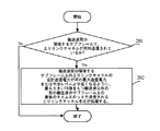
図2を参照する。図2は、本発明の実施形態1による、上り送信電力制御の方法のフローチャートである。図2に示すように、この方法は下記のステップを含み得る。
Embodiment 1
Refer to FIG. FIG. 2 is a flowchart of a method for uplink transmission power control according to Embodiment 1 of the present invention. As shown in FIG. 2, the method may include the following steps.
201:搬送波間の隣接するサブフレームが部分的にオーバーラップし、オーバーラップする領域が1シンボルに等しいかそれより小さく、また、複数搬送波の各搬送波が異なるTA値をもつとき、UEは、上りリンクチャネルが搬送波間の隣接するサブフレームで同時に送信されているかどうか判定する。判定が「Yes」の場合はステップ202を実行し、「No」の場合は手順を終了する。
201: When adjacent subframes between carriers partially overlap, the overlapping area is equal to or smaller than one symbol, and each carrier of multiple carriers has a different TA value, the UE It is determined whether the link channel is transmitted simultaneously in adjacent subframes between carriers. If the determination is “Yes”,
本発明のこの実施形態では、異なるTA値をもつ搬送波は、異なるTAGに属する搬送波であり得る。異なるTAGに属する搬送波のTA値は異なる。 In this embodiment of the invention, carriers with different TA values can be carriers belonging to different TAGs. The TA values of carriers belonging to different TAGs are different.
本発明のこの実施形態では、上記の上りリンクチャネルは、物理上りリンク制御チャネル(Physical Uplink Control Channel、PUCCH)、物理上りリンク共用チャネル(Physical Uplink Shared Channel、PUSCH)、サウンディング参照信号(Sounding Reference Signal、SRS)、または物理ランダムアクセスチャネル(Physical Random Access Channel、PRACH)であり得るが、これは、本発明のこの実施形態において特に限定されるものではない。 In this embodiment of the present invention, the uplink channel includes a physical uplink control channel (Physical Uplink Control Channel, PUCCH), a physical uplink shared channel (Physical Uplink Shared Channel, PUSCH), a sounding reference signal (Sounding Reference Signal). , SRS), or Physical Random Access Channel (PRACH), but this is not particularly limited in this embodiment of the invention.
本発明のこの実施形態では、異なるTA値をもつ搬送波間の隣接するサブフレームで上りリンクチャネルが同時に送信される場合、異なるTA値をもつ搬送波間の隣接するサブフレームは部分的にオーバーラップし、オーバーラップする領域は1シンボルに等しいかそれより小さい。例えば、セルの半径が10km(10kmは、一般的なセルの最大半径である)で、搬送波1および搬送波2が同時に、それぞれセル内のマクロ基地局(Marco ENB)およびマイクロ基地局(Picco ENB)からのUEにサービスを行うと仮定する。マイクロ基地局は、マクロ基地局によりカバーされているセルの縁部にあり、UEへの距離は非常に近く(つまり、搬送波2のTA値は、ほぼ0)、搬送波1と搬送波2との間のTA値の最大差は、マクロ基地局からUEまでの時間(10×103)/(3×108)=33.33マイクロ秒で、標準的な1シンボルの長さは1/14=71マイクロ秒である。図1のオーバーラップ領域は、1シンボルを超えないことがわかる。 In this embodiment of the present invention, when uplink channels are transmitted simultaneously in adjacent subframes between carriers with different TA values, adjacent subframes between carriers with different TA values partially overlap. The overlapping area is less than or equal to one symbol. For example, if the cell radius is 10km (10km is the maximum radius of a typical cell), carrier 1 and carrier 2 are simultaneously the macro base station (Marco ENB) and micro base station (Picco ENB) in the cell, respectively. Assume that the UE serves the UE. The micro base station is at the edge of the cell covered by the macro base station, and the distance to the UE is very close (that is, the TA value of carrier 2 is almost 0), between carrier 1 and carrier 2 The maximum difference in TA value is the time from the macro base station to the UE (10 × 10 3 ) / (3 × 10 8 ) = 33.33 microseconds, and the standard symbol length is 1/14 = 71 microseconds. Seconds. It can be seen that the overlap region in FIG. 1 does not exceed one symbol.
異なるTA値をもつ複数の搬送波の間の隣接するサブフレームで上りリンクチャネルが同時に送信されているとき、複数の搬送波間の隣接するサブフレームは部分的にオーバーラップし、オーバーラップする領域は1シンボルに等しいかそれより小さいという客観的な法則が存在する。本発明のこの実施形態に記載されるシンボルは、直交周波数分割多重方式(Orthogonal Frequency Division Multiplexing、OFDM)のシンボルである。 When uplink channels are transmitted simultaneously in adjacent subframes between multiple carriers with different TA values, adjacent subframes between multiple carriers partially overlap, and the overlapping region is 1 There is an objective law that is less than or equal to a symbol. The symbols described in this embodiment of the present invention are Orthogonal Frequency Division Multiplexing (OFDM) symbols.
202:UEは、搬送波間の隣接するサブフレーム上の上りリンクチャネルの合計送信電力がUEの最大送信電力または干渉レベルより低くなるように、最も大きいTA値をもつ搬送波以外の別の搬送波のサブフレームの最後のシンボルで送信される上りリンクチャネルを処理する。 202: The UE is a subcarrier of another carrier other than the carrier with the largest TA value so that the total transmission power of the uplink channel on adjacent subframes between the carriers is lower than the UE's maximum transmission power or interference level. Process the uplink channel transmitted in the last symbol of the frame.
本発明のこの実施形態では、干渉レベルもまた、電力の形で表現される。上りリンクチャネルの合計送信電力が干渉レベルよりも低い場合、上りリンクチャネルから別の隣接セルへの干渉は比較的小さいことが示される。それ以外の場合は、上りリンクチャネルから別の隣接セルへの干渉が比較的大きいことが示される。干渉レベルは、当業者が実際の状況に従って設定することができる。 In this embodiment of the invention, the interference level is also expressed in the form of power. If the total transmission power of the uplink channel is lower than the interference level, it indicates that the interference from the uplink channel to another neighboring cell is relatively small. In other cases, it is indicated that the interference from the uplink channel to another adjacent cell is relatively large. The interference level can be set according to the actual situation by those skilled in the art.
図1に示される搬送波1および搬送波2を例として使用する。搬送波1のTA値の絶対値は、搬送波2のTA値の絶対値より小さい。搬送波2のサブフレームnの信号が送信され、サブフレームn+1の信号の送信が開始されるとき、搬送波1はサブフレームnの信号をまだ送信中であり、最も大きいTA値をもつ搬送波とは、絶対値が最も大きいTA値をもつ搬送波を指す。図1で、絶対値が最も大きいTA値をもつ搬送波は、搬送波2である。UEは、搬送波2以外で最も大きいTA値をもつ別の搬送波のサブフレーム、例えば、搬送波1のサブフレームn(搬送波1のサブフレームnは搬送波2のサブフレームn+1と部分的にオーバーラップする)などの最後のシンボルで送信される上りリンクチャネルを処理して、搬送波1のサブフレームnおよび搬送波2のサブフレームn+1上の上りリンクチャネルの合計送信電力が、UEの最大送信電力または干渉レベルより小さくなるようにし得る。図1で、最も大きいTA値をもつ搬送波は搬送波2であり、最も大きいTA値をもつ搬送波以外の別の搬送波のサブフレームは、搬送波1のサブフレームnである。 The carrier 1 and the carrier 2 shown in FIG. 1 are used as an example. The absolute value of the TA value of carrier 1 is smaller than the absolute value of the TA of carrier 2. When the signal of subframe n of carrier 2 is transmitted and transmission of the signal of subframe n + 1 is started, carrier 1 is still transmitting the signal of subframe n, and the carrier with the largest TA value Denotes a carrier having a TA value having the largest absolute value. In FIG. 1, the carrier wave having the TA value having the largest absolute value is carrier wave 2. The UE may subframe another carrier with the largest TA value other than carrier 2, e.g. subframe n of carrier 1 (subframe n of carrier 1 partially overlaps subframe n + 1 of carrier 2 Processing the uplink channel transmitted in the last symbol, etc., and the total transmission power of the uplink channel on subframe n of carrier 1 and subframe n + 1 of carrier 2 is the maximum transmission power of the UE Or it can be made smaller than the interference level. In FIG. 1, the carrier with the largest TA value is carrier 2, and the subframe of another carrier other than the carrier with the largest TA value is subframe n of carrier 1.
異なるTA値をもつ搬送波の数が特に2つであり得るとき、実装可能な態様で、UEは、最も大きいTA値をもつ搬送波の上りリンクチャネル送信電力をUEの最大送信電力から減算して電力ヘッドルームを求め、この電力ヘッドルームを、最も大きいTA値をもつ搬送波以外の別の搬送波のサブフレームの最後のシンボルで送信される上りリンクチャネルの送信電力として使用して、搬送波間の隣接するサブフレーム上の上りリンクチャネルの合計送信電力が、UEの最大送信電力または干渉レベルより低くなるようにし得る。 In an implementable manner, when the number of carriers with different TA values may be two, the UE subtracts the uplink channel transmission power of the carrier with the largest TA value from the UE's maximum transmission power. Determine the headroom and use this power headroom as the transmit power of the uplink channel transmitted in the last symbol of the subframe of another carrier other than the carrier with the largest TA value, and adjacent between the carriers The total transmission power of the uplink channel on the subframe may be lower than the maximum transmission power or interference level of the UE.
または、異なるTA値をもつ搬送波の数が2つより多いとき、実装可能な別の態様で、UEは、最も大きいTA値をもつ搬送波以外の別の搬送波のサブフレームの最後のシンボルで送信される上りリンクチャネルに、均等に電力ヘッドルームを割り当てて、搬送波間の隣接するサブフレーム上の上りリンクチャネルの合計送信電力がUEの最大送信電力または干渉レベルより低くなるようにし得る。 Or, when there are more than two carriers with different TA values, in another manner that can be implemented, the UE is transmitted in the last symbol of a subframe of another carrier other than the carrier with the largest TA value. The uplink channel may be equally allocated power headroom so that the total transmit power of the uplink channel on adjacent subframes between carriers is lower than the maximum transmit power or interference level of the UE.
図1の搬送波1および搬送波2を例として使用する。UEは、搬送波2の上りリンクチャネル送信電力をUEの最大送信電力から減算して電力ヘッドルームを求め、この電力ヘッドルームを、搬送波1のサブフレームnの最後のシンボルで送信される上りリンクチャネルの送信電力として使用して、搬送波1のサブフレームnおよび搬送波2のサブフレームn+1上の上りリンクチャネルの合計送信電力が、UEの最大送信電力または干渉レベルより低くなるようにし得る。 Carrier 1 and carrier 2 in FIG. 1 are used as examples. The UE subtracts the uplink channel transmission power of carrier 2 from the maximum transmission power of the UE to obtain power headroom, and this power headroom is the uplink channel transmitted in the last symbol of subframe n of carrier 1 As the transmission power of the carrier, the total transmission power of the uplink channel on subframe n of carrier 1 and subframe n + 1 of carrier 2 may be lower than the maximum transmission power or interference level of the UE.
最も大きいTA値をもつ搬送波以外の別の搬送波のサブフレーム上の上りリンクチャネルが、SRS、PUCCHの最後のシンボル、PUSCHの最後のシンボルなどのいずれか1つを含むとき、実装可能な態様で、UEは、別の搬送波のサブフレームの最後のシンボルで送信される上りリンクチャネルをドロップして、搬送波間の隣接するサブフレーム上の上りリンクチャネルの合計送信電力が、UEの最大送信電力または干渉レベルより低くなるようにし得る。 In an implementable manner when the uplink channel on a subframe of another carrier other than the carrier with the largest TA value includes one of SRS, the last symbol of PUCCH, the last symbol of PUSCH, etc. , The UE drops the uplink channel transmitted in the last symbol of the subframe of another carrier, and the total transmission power of the uplink channel on adjacent subframes between carriers is equal to the maximum transmission power of the UE or It can be made lower than the interference level.
図1の搬送波1および搬送波2を例として使用する。搬送波1のサブフレームnの上りリンクチャネルがSRSの場合、UEは、搬送波1のサブフレームnの最後のシンボルで送信される上りリンクチャネルをドロップして、搬送波1のサブフレームnおよび搬送波2のサブフレームn+1上の上りリンクチャネルの合計送信電力が、UEの最大送信電力または干渉レベルより低くなるようにし得る。 Carrier 1 and carrier 2 in FIG. 1 are used as examples. If the uplink channel of subframe n of carrier 1 is SRS, the UE drops the uplink channel transmitted in the last symbol of subframe n of carrier 1 and subframes n and 2 of carrier 1 The total transmission power of the uplink channel on subframe n + 1 may be lower than the maximum transmission power or interference level of the UE.
最も大きいTA値をもつ搬送波以外の別の搬送波のサブフレーム上の上りリンクチャネルがPUCCHであるとき、実装可能な態様で、UEは、別の搬送波のサブフレームに、短縮された上りリンクチャネル送信形式を使用して、サブフレームの最後のシンボル上の送信がnullになるように、また、搬送波間の隣接するサブフレーム上の上りリンクチャネルの合計送信電力がUEの最大送信電力または干渉レベルより低くなるようにし得る。 In an implementable manner, when the uplink channel on another carrier subframe other than the carrier with the largest TA value is PUCCH, the UE may transmit a shortened uplink channel transmission to another carrier subframe. Format, so that the transmission on the last symbol of the subframe is null, and the total transmit power of the uplink channel on adjacent subframes between carriers is less than the maximum transmit power or interference level of the UE Can be lowered.
図1の搬送波1および搬送波2を例として使用する。搬送波1のサブフレームnの上りリンクチャネルがPUCCHの場合、UEは、搬送波1のサブフレームnに、短縮されたPUCCH形式を使用して、搬送波1のサブフレームnの最後のシンボル上の送信がnullになるように、また、搬送波1のサブフレームnおよび搬送波2のサブフレームn+1上の上りリンクチャネルの合計送信電力が、UEの最大送信電力または干渉レベルより低くなるようにし得る。 Carrier 1 and carrier 2 in FIG. 1 are used as examples. If the uplink channel of carrier 1 subframe n is PUCCH, the UE uses the shortened PUCCH format for carrier 1 subframe n and transmits on the last symbol of carrier 1 subframe n. The total transmission power of the uplink channel on subframe n of carrier 1 and subframe n + 1 of carrier 2 may be made to be null and lower than the maximum transmission power or interference level of the UE.
最も大きいTA値をもつ搬送波以外の別の搬送波のサブフレーム上の上りリンクチャネルがPUSCHであるとき、実装可能な態様で、UEは、別の搬送波のサブフレーム上の上りリンクチャネルの速度を一致させて、サブフレームの最後のシンボル上の送信がnullになるように、また、搬送波間の隣接するサブフレーム上の上りリンクチャネルの合計送信電力がUEの最大送信電力または干渉レベルより低くなるようにし得る。 When the uplink channel on a subframe of another carrier other than the carrier with the largest TA value is PUSCH, the UE matches the speed of the uplink channel on the subframe of another carrier in an implementable manner. The transmission on the last symbol of the subframe is null, and the total transmission power of the uplink channel on adjacent subframes between carriers is lower than the maximum transmission power or interference level of the UE. Can be.
図1の搬送波1および搬送波2を例として使用する。搬送波1のサブフレームnの上りリンクチャネルがPUSCHの場合、UEは、搬送波1のサブフレームn上の上りリンクチャネルの速度を一致させて、搬送波1のサブフレームnの最後のシンボル上の送信がnullになるように、また、搬送波1のサブフレームnおよび搬送波2のサブフレームn+1上の上りリンクチャネルの合計送信電力が、UEの最大送信電力または干渉レベルより低くなるようにし得る。 Carrier 1 and carrier 2 in FIG. 1 are used as examples. If the uplink channel of subframe n of carrier 1 is PUSCH, the UE matches the speed of the uplink channel on subframe n of carrier 1 and transmits on the last symbol of subframe n of carrier 1 The total transmission power of the uplink channel on subframe n of carrier 1 and subframe n + 1 of carrier 2 may be made to be null and lower than the maximum transmission power or interference level of the UE.
最も大きいTA値をもつ搬送波以外の別の搬送波のサブフレーム上の上りリンクチャネルがPRACHであり、別の搬送波のサブフレームはプリアンブルの送信に使用される最後のサブフレームではないとき、実装可能な態様で、UEは、別の搬送波のサブフレームの最後のシンボルで送信される上りリンクチャネルをドロップして、搬送波間の隣接するサブフレーム上の上りリンクチャネルの合計送信電力がUEの最大送信電力または干渉レベルより低くなるようにし得る。 Implementable when the uplink channel on another carrier subframe other than the carrier with the largest TA value is PRACH and the other carrier subframe is not the last subframe used to transmit the preamble In an aspect, the UE drops an uplink channel transmitted in the last symbol of a subframe of another carrier, and the total transmission power of uplink channels on adjacent subframes between carriers is the maximum transmission power of the UE Or, it may be lower than the interference level.
図1の搬送波1および搬送波2を例として使用する。搬送波1のサブフレームnの上りリンクチャネルがPRACHの場合、UEがPRACH上で送信するプリアンブル(preamble)は、1つから3つのサブフレームを占め得る。搬送波1のサブフレームnが、UEがpreambleを送信する最後のサブフレームではない場合、搬送波1のサブフレームnの最後のシンボルで送信されるPRACHはドロップされて、搬送波1のサブフレームnおよび搬送波2のサブフレームn+1上の上りリンクチャネルの合計送信電力が、UEの最大送信電力または干渉レベルより低くなるようにされ得る。搬送波1のサブフレームnが、UEがpreambleを送信する最後のサブフレームである場合、搬送波1のサブフレームnの最後のシンボルで送信されるPRACHは処理される必要がない。その理由は、preambleはPRACHの資源全体を占めず、搬送波1のサブフレームnの最後のシンボルは、保護周波数帯の範囲内にあるからである。 Carrier 1 and carrier 2 in FIG. 1 are used as examples. When the uplink channel of subframe n of carrier 1 is PRACH, the preamble that the UE transmits on PRACH may occupy 1 to 3 subframes. If subframe n of carrier 1 is not the last subframe in which the UE transmits a preamble, the PRACH transmitted in the last symbol of subframe n of carrier 1 is dropped and subframe n and carrier of carrier 1 are dropped. The total transmission power of the uplink channel on the two subframes n + 1 may be made lower than the maximum transmission power or interference level of the UE. If subframe n of carrier 1 is the last subframe in which the UE transmits a preamble, the PRACH transmitted in the last symbol of subframe n of carrier 1 need not be processed. The reason is that the preamble does not occupy the entire PRACH resource, and the last symbol of the subframe n of the carrier 1 is within the range of the protection frequency band.
本発明の実施形態1では、UEが、異なるTAGに属する搬送波を通じて上りリンクチャネルを送信し、異なるTAGに属する搬送波間の隣接するサブフレームが部分的にオーバーラップするとき、UEの上り送信電力がUEの最大送信電力を越えて電力限界に至ること、または、UEの上り送信電力が干渉レベルに達して干渉限界に至ることが防がれ得る。 In Embodiment 1 of the present invention, when the UE transmits an uplink channel through carriers belonging to different TAGs, and the adjacent subframes between the carriers belonging to different TAGs partially overlap, the uplink transmission power of the UE is It may be prevented that the maximum transmission power of the UE is exceeded and the power limit is reached, or the uplink transmission power of the UE reaches the interference level and reaches the interference limit.
実施形態2
図3を参照する。図3は、本発明の実施形態2による、上り送信電力制御の方法のフローチャートである。上記の実施形態1で、異なるTA値をもつ搬送波間の隣接するサブフレーム上の上りリンクチャネルの合計送信電力は、UEの最大送信電力または干渉レベルを超えなくなり得る。処理が常に実施形態1に記載された方法によって実行される場合、上り送信電力の浪費が一定の度合いで存在し得る。本発明の実施形態2では、実施形態1で発生し得る上り送信電力の浪費の問題が解決され得る。図3に示すように、この方法は下記のステップを含み得る。
Embodiment 2.
Refer to FIG. FIG. 3 is a flowchart of a method for uplink transmission power control according to Embodiment 2 of the present invention. In Embodiment 1 above, the total transmission power of uplink channels on adjacent subframes between carriers with different TA values may not exceed the maximum transmission power or interference level of the UE. If the processing is always performed by the method described in Embodiment 1, the waste of uplink transmission power may exist to a certain degree. In Embodiment 2 of the present invention, the problem of waste of uplink transmission power that may occur in Embodiment 1 can be solved. As shown in FIG. 3, the method may include the following steps:
301:搬送波間の隣接するサブフレームが部分的にオーバーラップし、オーバーラップする領域が1シンボルに等しいかそれより小さく、また、各搬送波が異なるTA値をもつとき、UEは、上りリンクチャネルが搬送波間の隣接するサブフレームで同時に送信されているかどうか判定する。判定が「Yes」の場合はステップ302を実行し、「No」の場合は手順を終了する。
301: When adjacent subframes between carriers partially overlap, the overlapping region is less than or equal to one symbol, and each carrier has a different TA value, the UE It is determined whether or not simultaneous transmission is performed in adjacent subframes between carriers. If the determination is “Yes”,
302:UEは、搬送波間の隣接するサブフレーム上の上りリンクチャネルの合計送信電力がUEの最大送信電力または干渉レベルを超えているかどうか判定する。判定が「Yes」の場合はステップ303を実行し、「No」の場合はステップ304を実行する。
302: The UE determines whether the total transmission power of uplink channels on adjacent subframes between carriers exceeds the maximum transmission power or interference level of the UE. If the determination is “Yes”,
303:UEは、搬送波間の隣接するサブフレーム上の上りリンクチャネルの合計送信電力がUEの最大送信電力または干渉レベルより低くなるように、最も大きいTA値をもつ搬送波以外の別の搬送波の、部分的にオーバーラップしたサブフレームの最後のシンボルで送信される上りリンクチャネルを処理する。 303: The UE has another carrier other than the carrier with the largest TA value, such that the total transmission power of the uplink channel on adjacent subframes between the carriers is lower than the maximum transmission power or interference level of the UE. The uplink channel transmitted in the last symbol of the partially overlapping subframe is processed.
ステップ303の特定の実装の態様は、実施形態1のステップ202に詳細に記載されており、本発明の実施形態2では繰り返されない。
The particular implementation aspect of
304:UEは、搬送波間の隣接するサブフレームでの上りリンクチャネルの同時送信を、隣接するサブフレームのオーバーラップ範囲内で許可する。 304: The UE allows simultaneous transmission of uplink channels in adjacent subframes between carriers within an overlap range of adjacent subframes.
本発明の実施形態2では、UEが、異なるTAGに属する搬送波を通じて上りリンクチャネルを送信し、異なるTAGに属する搬送波間の隣接するサブフレームが部分的にオーバーラップするとき、UEの上り送信電力がUEの最大送信電力を越えて電力限界に至ること、または、UEの上り送信電力が干渉レベルに達して干渉限界に至ることが防がれ得る。さらに、本発明の実施形態2ではまた、上り送信電力の浪費が削減され得る。 In Embodiment 2 of the present invention, when the UE transmits an uplink channel through carriers belonging to different TAGs, and the adjacent subframes between carriers belonging to different TAGs partially overlap, the uplink transmission power of the UE is It may be prevented that the maximum transmission power of the UE is exceeded and the power limit is reached, or the uplink transmission power of the UE reaches the interference level and reaches the interference limit. Furthermore, in Embodiment 2 of the present invention, the waste of uplink transmission power can also be reduced.
本発明の実施形態で提供される上り送信電力制御の方法は、上記に、明瞭かつ完全に記載されている。UEはENBに、最も大きいTA値をもつ搬送波以外の別の搬送波のサブフレームの最後のシンボルで送信される上りリンクチャネルを処理するときを通知しないので、ENBが復号を行うとき、復号エラーが発生し得る。この問題を解決するために、ENBは次の動作を実行し得る。1.ENBは、「UEは、最も大きいTA値をもつ搬送波以外の別の搬送波のサブフレームの最後のシンボルで送信される上りリンクチャネルを処理しない」、および「UEは、最も大きいTA値をもつ搬送波以外の別の搬送波のサブフレームの最後のシンボルで送信される上りリンクチャネルを処理し、復号を2回行って、ENBが正しい復号を得られるようする」と、それぞれ仮定する。2.復号エラーの後、ENBはUEにNACKを送信し、UEに再送信を実行させるが、上りリンクのパフォーマンスは低下し得る。 The method of uplink transmission power control provided in the embodiments of the present invention has been clearly and completely described above. Since the UE does not inform the ENB when to process the uplink channel transmitted in the last symbol of a subframe of another carrier other than the carrier with the largest TA value, when the ENB performs decoding, a decoding error will occur. Can occur. In order to solve this problem, the ENB may perform the following operations. 1. The ENB states that “UE does not process the uplink channel transmitted in the last symbol of a subframe of another carrier other than the carrier with the highest TA value” and “UE does not handle the highest TA value. It is assumed that the uplink channel transmitted in the last symbol of the sub-frame of another carrier other than the carrier having the other carrier is processed and the decoding is performed twice so that the ENB can obtain the correct decoding. 2. After a decoding error, the ENB sends a NACK to the UE and causes the UE to perform retransmission, but uplink performance may be degraded.
実施形態3
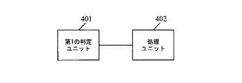
図4を参照する。図4は、本発明の実施形態3による、ユーザ装置の構造図である。本発明の実施形態3によるユーザ装置は、携帯電話および携帯用コンピュータであり得る。図4に示すように、ユーザ装置は、
搬送波間の隣接するサブフレームが部分的にオーバーラップし、オーバーラップする領域が1シンボルに等しいかそれより小さく、各搬送波が異なるTA値をもつとき、上りリンクチャネルが搬送波間の隣接するサブフレームで同時に送信されているかどうか判定するよう構成される、第1の判定ユニット401と、
第1の判定ユニット401の判定結果が「Yes」のとき、搬送波間の隣接するサブフレーム上の上りリンクチャネルの合計送信電力がユーザ装置の最大送信電力または干渉レベルより低くなるように、最も大きいTA値をもつ搬送波以外の別の搬送波のサブフレームの最後のシンボルで送信される上りリンクチャネルを処理するよう構成される、処理ユニット402とを備え得る。
Embodiment 3.
Refer to FIG. FIG. 4 is a structural diagram of a user apparatus according to Embodiment 3 of the present invention. The user equipment according to Embodiment 3 of the present invention may be a mobile phone and a portable computer. As shown in FIG. 4, the user equipment
When adjacent subframes between carriers partially overlap, the overlapping area is less than or equal to one symbol, and each carrier has a different TA value, the uplink channel has adjacent subframes between carriers A
When the determination result of the
異なるTA値をもつ搬送波の数が2つであるとき、実装可能な値において、処理ユニット402は、最も大きいTA値をもつ搬送波の上りリンクチャネル送信電力をユーザ装置の最大送信電力から減算して電力ヘッドルームを求め、この電力ヘッドルームを、最も大きいTA値をもつ搬送波以外の別の搬送波のサブフレームの最後のシンボルで送信される上りリンクチャネルの送信電力として使用して、搬送波間の隣接するサブフレーム上の上りリンクチャネルの合計送信電力が、UEの最大送信電力または干渉レベルより低くなるようにするよう、特に構成される。
When the number of carriers with different TA values is two, in an implementable value, the
別法として、異なるTA値をもつ搬送波の数が2つより多いとき、処理ユニット402は、最も大きいTA値をもつ搬送波の上りリンクチャネル送信電力をユーザ装置の最大送信電力から減算して電力ヘッドルームを求め、この電力ヘッドルームを、最も大きいTA値をもつ搬送波以外の別の搬送波のサブフレームの最後のシンボルで送信される上りリンクチャネルに均等に割り当てて、搬送波間の隣接するサブフレーム上の上りリンクチャネルの合計送信電力がUEの最大送信電力または干渉レベルより低くなるようにするよう、特に構成される。
Alternatively, when there are more than two carriers with different TA values, the
最も大きいTA値をもつ搬送波以外の別の搬送波のサブフレーム上の上りリンクチャネルが、SRS、PUCCHの最後のシンボル、PUSCHの最後のシンボルなどのいずれか1つを含むとき、実装可能な態様で、処理ユニット402は、別の搬送波のサブフレームの最後のシンボルで送信される上りリンクチャネルをドロップして、搬送波間の隣接するサブフレーム上の上りリンクチャネルの合計送信電力がユーザ装置の最大送信電力または干渉レベルより低くなるようにするよう、特に構成される。
In an implementable manner when the uplink channel on a subframe of another carrier other than the carrier with the largest TA value includes one of SRS, the last symbol of PUCCH, the last symbol of PUSCH, etc. ,
最も大きいTA値をもつ搬送波以外の別の搬送波のサブフレーム上の上りリンクチャネルがPUCCHであるとき、実装可能な態様で、処理ユニット402は、別の搬送波のサブフレームに、短縮された上りリンクチャネル送信形式を使用して、サブフレームの最後のシンボル上の送信がnullになるように、また、搬送波間の隣接するサブフレーム上の上りリンクチャネルの合計送信電力がユーザ装置の最大送信電力または干渉レベルより低くなるようにするよう、特に構成される。
In an implementable manner, when the uplink channel on another carrier subframe other than the carrier with the largest TA value is PUCCH, processing
最も大きいTA値をもつ搬送波以外の別の搬送波のサブフレーム上の上りリンクチャネルがPUSCHであるとき、実装可能な値において、処理ユニット402は、別の搬送波のサブフレーム上の上りリンクチャネルの速度を一致させて、サブフレームの最後のシンボル上の送信がnullになるように、また、搬送波間の隣接するサブフレーム上の上りリンクチャネルの合計送信電力がユーザ装置の最大送信電力または干渉レベルより低くなるようにするよう、特に構成される。
When the uplink channel on a subframe of another carrier other than the carrier with the largest TA value is PUSCH, in an implementable value, the
最も大きいTA値をもつ搬送波以外の別の搬送波のサブフレーム上の上りリンクチャネルがPRACHであり、別の搬送波のサブフレームはプリアンブルの送信に使用される最後のサブフレームではないとき、実装可能な態様で、処理ユニット402は、別の搬送波のサブフレームの最後のシンボルで送信される上りリンクチャネルをドロップして、搬送波間の隣接するサブフレーム上の上りリンクチャネルの合計送信電力がユーザ装置の最大送信電力または干渉レベルより低くなるようにするよう、特に構成される。
Implementable when the uplink channel on another carrier subframe other than the carrier with the largest TA value is PRACH and the other carrier subframe is not the last subframe used to transmit the preamble In an aspect, the
本発明の実施形態3で提供されるユーザ装置では、UEが、異なるTAGに属する搬送波を通じて上りリンクチャネルを送信し、異なるTAGに属する搬送波間の隣接するサブフレームが部分的にオーバーラップするとき、UEの上り送信電力がUEの最大送信電力を越えて電力限界に至ること、または、UEの上り送信電力が干渉レベルに達して干渉限界に至ることが防がれ得る。 In the user apparatus provided in Embodiment 3 of the present invention, when the UE transmits an uplink channel through carriers belonging to different TAGs, and adjacent subframes between carriers belonging to different TAGs partially overlap, It can be prevented that the uplink transmission power of the UE exceeds the maximum transmission power of the UE and reaches the power limit, or the uplink transmission power of the UE reaches the interference level and reaches the interference limit.
実施形態4
図5を参照する。図5は、本発明の実施形態4によるユーザ装置の構造図である。本発明の実施形態4によるユーザ装置は、図4に示されるユーザ装置を最適化することにより得られ得る。図5に示すように、ユーザ装置は第1の判定ユニット401および処理ユニット402を含むだけではなく、さらに第2の判定ユニット403を含み得る。
Embodiment 4.
Refer to FIG. FIG. 5 is a structural diagram of a user apparatus according to Embodiment 4 of the present invention. The user equipment according to Embodiment 4 of the present invention can be obtained by optimizing the user equipment shown in FIG. As shown in FIG. 5, the user apparatus not only includes a
第2の判定ユニット403は、第1の判定ユニット401の判定結果が「Yes」である場合、搬送波間の隣接するサブフレーム上の上りリンクチャネルの合計送信電力が、ユーザ装置の最大送信電力または干渉レベルを超えるかどうか判定するよう構成される。
When the determination result of the
同様に、処理ユニット402は、第2の判定ユニット403の判定結果が「Yes」である場合、搬送波間の隣接するサブフレーム上の上りリンクチャネルの合計送信電力がユーザ装置の最大送信電力または干渉レベルより低くなるように、最も大きいTA値をもつ搬送波以外の別の搬送波のサブフレームの最後のシンボルで送信される上りリンクチャネルを処理するよう構成される。
Similarly, when the determination result of the
別法として、処理ユニットはまた、第2の判定ユニット403の判定結果が「No」である場合、搬送波間の隣接するサブフレームでの上りリンクチャネルの同時送信を、隣接するサブフレームのオーバーラップ範囲内で許可するよう構成される。
Alternatively, the processing unit may also transmit simultaneous uplink channel transmissions in adjacent subframes between carriers when the determination result of the
本発明の実施形態4で提供されるユーザ装置では、UEが、異なるTAGに属する搬送波を通じて上りリンクチャネルを送信し、異なるTAGに属する搬送波間の隣接するサブフレームが部分的にオーバーラップするとき、UEの上り送信電力がUEの最大送信電力を越えて電力限界に至ること、または、UEの上り送信電力が干渉レベルに達して干渉限界に至ることが防がれ得る。さらに、本発明の実施形態4で提供されるユーザ装置はまた、上り送信電力の浪費を削減し得る。 In the user apparatus provided in Embodiment 4 of the present invention, when the UE transmits an uplink channel through carriers belonging to different TAGs, and adjacent subframes between carriers belonging to different TAGs partially overlap, It can be prevented that the uplink transmission power of the UE exceeds the maximum transmission power of the UE and reaches the power limit, or the uplink transmission power of the UE reaches the interference level and reaches the interference limit. Furthermore, the user apparatus provided in Embodiment 4 of the present invention can also reduce waste of uplink transmission power.
上記の実施形態における方法のステップのすべてまたは一部は、プログラム命令に関連するハードウェアにより実装し得ることが、当業者には理解されよう。プログラムは、コンピュータ読み取り可能な記憶媒体に記憶され得る。記憶媒体には、フラッシュメモリ、リードオンリメモリ(Read-Only Memory、ROM)、ランダムアクセスメモリ(Random Access Memory、RAM)、磁気ディスク、または光ディスクが含まれ得る。 Those skilled in the art will appreciate that all or part of the method steps in the above embodiments may be implemented by hardware associated with program instructions. The program can be stored in a computer-readable storage medium. The storage medium may include a flash memory, a read-only memory (Read-Only Memory, ROM), a random access memory (Random Access Memory, RAM), a magnetic disk, or an optical disk.
上記に、本発明の実施形態で提供される上り送信電力制御の方法およびユーザ装置について詳細に記載した。本発明の原理および実装の態様について、本明細書の具体例を使用して記載した。上記の実施形態の記載は、本発明の方法および核心概念の理解を助けるためのみに使用されている。さらに、当業者であれば、本発明の概念に従って特定の実装の態様および適用範囲に対する修正を行うことができる。結論として、本明細書の内容は、本発明に対する限定と見なすべきではない。 The uplink transmission power control method and user apparatus provided in the embodiment of the present invention have been described in detail above. The principles and implementation aspects of the present invention have been described using specific examples herein. The descriptions of the above embodiments are only used to help understand the method and core concepts of the present invention. Further, those skilled in the art can make modifications to specific implementation aspects and scopes in accordance with the concepts of the present invention. In conclusion, the contents of this specification should not be taken as a limitation on the present invention.
401 第1の判定ユニット
402 処理ユニット
403 第2の判定ユニット
401 First judgment unit
402 processing unit
403 Second judgment unit
Claims (10)
上りリンクチャネルが複数の搬送波間の隣接するサブフレームで同時に送信されている場合、前記ユーザ装置が、上りリンクチャネルの合計送信電力が前記ユーザ装置の最大送信電力または干渉レベルを超えるかどうかを判定するステップと、
前記上りリンクチャネルの合計送信電力が前記ユーザ装置の最大送信電力または干渉レベルを超える場合、前記ユーザ装置が、別の搬送波の部分的にオーバーラップしたサブフレームの最後のシンボルで送信されるサウンディング参照信号(SRS)をドロップするステップとを備え、
前記別の搬送波は前記複数の搬送波において最も大きいタイミングアドバンス値をもつ搬送波以外の搬送波である、上りリンク送信電力制御の方法。 The user device comprises whether determining whether uplink channels are transmitted concurrently in adjacent sub-frame among a plurality of carriers, next contact sub-frames across the plurality of carriers are partially overlapping the timing advance values of the plurality of carriers is Tsu different,
When an uplink channel is simultaneously transmitted in adjacent subframes between a plurality of carriers, the user equipment determines whether the total transmission power of the uplink channel exceeds the maximum transmission power or interference level of the user equipment And steps to
If the total transmit power of the uplink channel exceeds the maximum transmit power or interference level of the user equipment, the user equipment is transmitted in the last symbol of a partially overlapping subframe of another carrier Dropping a signal (SRS),
The uplink transmission power control method, wherein the another carrier is a carrier other than the carrier having the largest timing advance value among the plurality of carriers .
物理上りリンク制御チャネル(PUCCH)、物理上りリンク共用チャネル(PUSCH)、物理ランダムアクセスチャネル(PRACH)のうち1つを含む、請求項1または2に記載の上りリンク送信電力制御の方法。The method of uplink transmission power control according to claim 1 or 2, comprising one of a physical uplink control channel (PUCCH), a physical uplink shared channel (PUSCH), and a physical random access channel (PRACH).
物理上りリンク制御チャネル(PUCCH)、物理上りリンク共用チャネル(PUSCH)、物理ランダムアクセスチャネル(PRACH)のうち1つを含む、請求項1または2に記載の上りリンク送信電力制御の方法。The method of uplink transmission power control according to claim 1 or 2, comprising one of a physical uplink control channel (PUCCH), a physical uplink shared channel (PUSCH), and a physical random access channel (PRACH).
前記上りリンクチャネルの合計送信電力が前記ユーザ装置の最大送信電力または干渉レベルを超える場合、別の搬送波の部分的にオーバーラップしたサブフレームの最後のシンボルで送信されるサウンディング参照信号(SRS)をドロップするように構成された第2の判定部を備え、前記別の搬送波は前記複数の搬送波において最も大きいタイミングアドバンス値をもつ搬送波以外の搬送波である、ユーザ装置。If the total transmission power of the uplink channel exceeds the maximum transmission power or interference level of the user equipment, a sounding reference signal (SRS) transmitted in the last symbol of a partially overlapping subframe of another carrier A user apparatus comprising a second determination unit configured to drop, wherein the another carrier is a carrier other than the carrier having the largest timing advance value in the plurality of carriers.
物理上りリンク制御チャネル(PUCCH)、物理上りリンク共用チャネル(PUSCH)、物理ランダムアクセスチャネル(PRACH)のうち1つを含む、請求項7または8に記載のユーザ装置。The user apparatus according to claim 7 or 8, comprising one of a physical uplink control channel (PUCCH), a physical uplink shared channel (PUSCH), and a physical random access channel (PRACH).
物理上りリンク制御チャネル(PUCCH)、物理上りリンク共用チャネル(PUSCH)、物理ランダムアクセスチャネル(PRACH)のうち1つを含む、請求項7または8に記載のユーザ装置。The user apparatus according to claim 7 or 8, comprising one of a physical uplink control channel (PUCCH), a physical uplink shared channel (PUSCH), and a physical random access channel (PRACH).
Applications Claiming Priority (3)
| Application Number | Priority Date | Filing Date | Title |
|---|---|---|---|
| CN201110426330.3 | 2011-12-19 | ||
| CN201110426330.3A CN103167594B (en) | 2011-12-19 | 2011-12-19 | Uplink transmitting power control method and user equipment |
| PCT/CN2012/085401 WO2013091465A1 (en) | 2011-12-19 | 2012-11-28 | Method and user equipment for controlling uplink transmission power |
Publications (2)
| Publication Number | Publication Date |
|---|---|
| JP2015501113A JP2015501113A (en) | 2015-01-08 |
| JP5895065B2 true JP5895065B2 (en) | 2016-03-30 |
Family
ID=48590245
Family Applications (1)
| Application Number | Title | Priority Date | Filing Date |
|---|---|---|---|
| JP2014547689A Active JP5895065B2 (en) | 2011-12-19 | 2012-11-28 | UPLINK TRANSMISSION POWER CONTROL METHOD AND USER DEVICE |
Country Status (7)
| Country | Link |
|---|---|
| US (2) | US9756581B2 (en) |
| EP (2) | EP2785119B1 (en) |
| JP (1) | JP5895065B2 (en) |
| CN (4) | CN104902555B (en) |
| BR (1) | BR112014014959B1 (en) |
| IN (1) | IN2014CN04946A (en) |
| WO (1) | WO2013091465A1 (en) |
Families Citing this family (33)
| Publication number | Priority date | Publication date | Assignee | Title |
|---|---|---|---|---|
| WO2012158959A1 (en) | 2011-05-17 | 2012-11-22 | Interdigital Patent Holdings, Inc. | Nodeb power adaptation for reducing references |
| US8395985B2 (en) | 2011-07-25 | 2013-03-12 | Ofinno Technologies, Llc | Time alignment in multicarrier OFDM network |
| EP3937551A3 (en) | 2012-01-25 | 2022-02-09 | Comcast Cable Communications, LLC | Random access channel in multicarrier wireless communications with timing advance groups |
| US9237537B2 (en) | 2012-01-25 | 2016-01-12 | Ofinno Technologies, Llc | Random access process in a multicarrier base station and wireless device |
| WO2013114799A1 (en) | 2012-01-30 | 2013-08-08 | パナソニック株式会社 | Wireless communication terminal device and method for controlling transmission power |
| US20130259008A1 (en) | 2012-04-01 | 2013-10-03 | Esmael Hejazi Dinan | Random Access Response Process in a Wireless Communications |
| US11943813B2 (en) | 2012-04-01 | 2024-03-26 | Comcast Cable Communications, Llc | Cell grouping for wireless communications |
| US11252679B2 (en) | 2012-04-16 | 2022-02-15 | Comcast Cable Communications, Llc | Signal transmission power adjustment in a wireless device |
| US11825419B2 (en) | 2012-04-16 | 2023-11-21 | Comcast Cable Communications, Llc | Cell timing in a wireless device and base station |
| US11582704B2 (en) | 2012-04-16 | 2023-02-14 | Comcast Cable Communications, Llc | Signal transmission power adjustment in a wireless device |
| US11622372B2 (en) | 2012-06-18 | 2023-04-04 | Comcast Cable Communications, Llc | Communication device |
| US11882560B2 (en) | 2012-06-18 | 2024-01-23 | Comcast Cable Communications, Llc | Carrier grouping in multicarrier wireless networks |
| US9107206B2 (en) | 2012-06-18 | 2015-08-11 | Ofinne Technologies, LLC | Carrier grouping in multicarrier wireless networks |
| WO2015139224A1 (en) * | 2014-03-19 | 2015-09-24 | Telefonaktiebolaget L M Ericsson(Publ) | Uplink power sharing in dual connectivity |
| CN105379373B (en) * | 2014-03-20 | 2019-11-29 | 华为技术有限公司 | A kind of transmission method and device of information |
| EP3133875B1 (en) | 2014-05-08 | 2020-04-22 | Huawei Technologies Co., Ltd. | Power distribution method and device |
| CN105493553B (en) * | 2014-08-05 | 2019-09-20 | 华为技术有限公司 | Terminal, the network equipment and ascending control information processing method |
| WO2016019686A1 (en) * | 2014-08-07 | 2016-02-11 | 深圳市中兴微电子技术有限公司 | A method for scheduling transmitting timing of uplink channels and device |
| EP3232594B1 (en) * | 2014-12-08 | 2020-02-05 | LG Electronics Inc. | Method and user equipment for transmitting pucch when more than five cells are used according to carrier aggregation |
| CN106685613B (en) | 2015-11-06 | 2020-04-10 | 电信科学技术研究院 | SRS transmission method and device |
| CN106851809B (en) | 2015-12-03 | 2020-11-17 | 华为技术有限公司 | Method for determining power and user equipment |
| EP3389318B1 (en) * | 2015-12-31 | 2020-09-16 | Huawei Technologies Co., Ltd. | Power information transmission method, terminal device, and network device |
| US10187191B2 (en) * | 2016-01-27 | 2019-01-22 | Qualcomm Incorporated | SRS transmission in management in carrier aggregation |
| US10117188B2 (en) * | 2016-04-01 | 2018-10-30 | Motorola Mobility Llc | Method and apparatus for scheduling uplink transmissions with reduced latency |
| AU2016406586B2 (en) | 2016-05-13 | 2020-02-13 | Huawei Technologies Co.,Ltd. | Power control method and apparatus |
| US10503684B2 (en) * | 2016-07-01 | 2019-12-10 | Intel Corporation | Multiple uplink port devices |
| ES2844274T3 (en) * | 2016-11-04 | 2021-07-21 | Asustek Comp Inc | Method and apparatus for beamforming operation on user equipment in a wireless communication system |
| US10517045B2 (en) | 2017-11-17 | 2019-12-24 | Qualcomm Incorporated | Techniques for power control using carrier aggregation in wireless communications |
| US10772061B2 (en) * | 2017-11-17 | 2020-09-08 | Qualcomm Incorporated | Handling overlapped communications |
| WO2020009511A1 (en) * | 2018-07-04 | 2020-01-09 | 엘지전자 주식회사 | Method for performing uplink transmission in wireless communication system, and device therefor |
| CN109041009B (en) * | 2018-07-06 | 2020-03-17 | 北京科技大学 | Internet of vehicles uplink power distribution method and device |
| CN112188550B (en) * | 2020-09-28 | 2022-12-06 | 展讯通信(上海)有限公司 | Data transmission method, wireless access point and computer readable storage medium |
| US11632776B2 (en) * | 2021-09-03 | 2023-04-18 | Qualcomm Incorporated | Techniques for handling overlapping transmissions after timing adjustment |
Family Cites Families (15)
| Publication number | Priority date | Publication date | Assignee | Title |
|---|---|---|---|---|
| GB2411078B (en) | 2004-02-10 | 2009-02-04 | Samsung Electronics Co Ltd | Mobile communications |
| RU2395915C2 (en) | 2005-05-04 | 2010-07-27 | Нокиа Корпорейшн | Method, device and computer program, providing for alarm on adjustable sizes of power control steps for high-speed packet access along ascending communication line |
| JP4829049B2 (en) * | 2006-08-30 | 2011-11-30 | 京セラ株式会社 | Wireless communication method and wireless base station |
| CN101527593B (en) * | 2008-03-05 | 2013-01-16 | 中兴通讯股份有限公司 | Method and device for removing interference between cells based on time division duplex wireless communication system |
| EP3010292B1 (en) * | 2009-02-03 | 2018-08-29 | Cellular Communications Equipment Llc | Uplink power control for multiple component |
| WO2010091425A2 (en) * | 2009-02-09 | 2010-08-12 | Interdigital Patent Holdings, Inc. | Apparatus and method for uplink power control for a wireless transmitter/receiver unit utilizing multiple carriers |
| US9144037B2 (en) * | 2009-08-11 | 2015-09-22 | Qualcomm Incorporated | Interference mitigation by puncturing transmission of interfering cells |
| CN102131278B (en) | 2010-01-13 | 2012-04-18 | 普天信息技术研究院有限公司 | Uplink power compression method and user equipment |
| KR101790593B1 (en) * | 2010-04-01 | 2017-10-26 | 선 페이턴트 트러스트 | Transmit power control for physical random access channels |
| KR101366335B1 (en) | 2010-04-01 | 2014-03-12 | 엘지전자 주식회사 | Method and apparatus for controlling uplink power in a wireless access system |
| CN102238716A (en) * | 2011-07-15 | 2011-11-09 | 电信科学技术研究院 | Method and device for adjusting transmitting power |
| CN108834205B (en) * | 2011-11-04 | 2021-09-28 | 交互数字专利控股公司 | Method and apparatus for power control for wireless transmissions on multiple component carriers associated with multiple timing advances |
| CN102378341A (en) * | 2011-11-17 | 2012-03-14 | 电信科学技术研究院 | Uplink power control method and device |
| CN102573030B (en) * | 2011-12-08 | 2014-11-05 | 电信科学技术研究院 | Uplink power control method and device |
| CN102572967B (en) * | 2012-01-13 | 2014-07-30 | 电信科学技术研究院 | Method, system and equipment for transmitting and receiving uplink information |
-
2011
- 2011-12-19 CN CN201510349726.0A patent/CN104902555B/en active Active
- 2011-12-19 CN CN201510349424.3A patent/CN104902554B/en active Active
- 2011-12-19 CN CN201110426330.3A patent/CN103167594B/en active Active
- 2011-12-19 CN CN201510349421.XA patent/CN104955144B/en active Active
-
2012
- 2012-11-28 BR BR112014014959-3A patent/BR112014014959B1/en active IP Right Grant
- 2012-11-28 WO PCT/CN2012/085401 patent/WO2013091465A1/en active Application Filing
- 2012-11-28 EP EP12860733.0A patent/EP2785119B1/en active Active
- 2012-11-28 EP EP17210614.8A patent/EP3373666B1/en active Active
- 2012-11-28 JP JP2014547689A patent/JP5895065B2/en active Active
- 2012-11-28 IN IN4946CHN2014 patent/IN2014CN04946A/en unknown
-
2014
- 2014-06-19 US US14/309,579 patent/US9756581B2/en active Active
-
2017
- 2017-08-03 US US15/668,299 patent/US10887846B2/en active Active
Also Published As
| Publication number | Publication date |
|---|---|
| CN104902554B (en) | 2018-05-29 |
| IN2014CN04946A (en) | 2015-09-18 |
| US20170332332A1 (en) | 2017-11-16 |
| US10887846B2 (en) | 2021-01-05 |
| BR112014014959B1 (en) | 2022-12-06 |
| EP2785119A4 (en) | 2014-10-01 |
| JP2015501113A (en) | 2015-01-08 |
| EP2785119B1 (en) | 2018-03-21 |
| US9756581B2 (en) | 2017-09-05 |
| CN104902555B (en) | 2018-04-20 |
| CN104955144A (en) | 2015-09-30 |
| EP3373666B1 (en) | 2022-03-16 |
| CN103167594A (en) | 2013-06-19 |
| CN103167594B (en) | 2015-05-27 |
| CN104955144B (en) | 2021-05-18 |
| WO2013091465A1 (en) | 2013-06-27 |
| CN104902554A (en) | 2015-09-09 |
| EP2785119A1 (en) | 2014-10-01 |
| BR112014014959A2 (en) | 2017-06-13 |
| EP3373666A1 (en) | 2018-09-12 |
| US20140314014A1 (en) | 2014-10-23 |
| CN104902555A (en) | 2015-09-09 |
Similar Documents
| Publication | Publication Date | Title |
|---|---|---|
| JP5895065B2 (en) | UPLINK TRANSMISSION POWER CONTROL METHOD AND USER DEVICE | |
| US20220210844A1 (en) | Method and apparatus for random access in wireless communication systems | |
| KR101923456B1 (en) | Method of transmitting or receiving a signal in a wireless communication system and Apparatus thereof | |
| JP6456471B2 (en) | Method and apparatus for setting transmission opportunity interval in wireless connection system supporting non-licensed band | |
| RU2687033C1 (en) | Transmitting a random access response message | |
| US10856337B2 (en) | Method and apparatus for random access in wireless communication system and user terminal | |
| WO2019101201A1 (en) | Random access method, user equipment, and storage medium | |
| EP2553860B1 (en) | Uplink sounding reference signals configuration and transmission | |
| US9374814B2 (en) | DCI transmission method and device under cross-band carrier aggregation | |
| US11653249B2 (en) | Disambiguation of random access response for random access support on supplemental uplink | |
| KR20210122812A (en) | Methods and Apparatus for Determining Effective RACH Opportunities in Unlicensed NRs | |
| RU2668569C1 (en) | Wireless device, network node and corresponding methods of providing opportunity and implementation of uplink control channel transmission | |
| WO2015122723A1 (en) | Method and apparatus for transmitting sounding reference signal in wireless access system supporting machine type communication | |
| TWI805032B (en) | Large cell support for narrowband random access | |
| WO2012146825A1 (en) | Cross-carrier preamble responses | |
| CN104272844A (en) | Network node, user equipment and methods therein for random access handling | |
| RU2742045C1 (en) | Terminal, a radio communication method and a base station | |
| WO2019176593A1 (en) | Terminal device, base station device, and communication method | |
| US20140112259A1 (en) | Signaling for Random Access in Time Division Duplexed (TDD) Systems with Traffic Adaptation | |
| WO2015170886A1 (en) | Signal processing method for low-cost device, and apparatus for same | |
| EP3141066A1 (en) | Method of reducing impact of d2d in-band interference on cellular transmission | |
| WO2017101799A1 (en) | Information transmission method and apparatus, and computer storage medium | |
| WO2017026324A1 (en) | Terminal device, communication method, and integrated circuit | |
| CN107800522A (en) | A kind of method and apparatus in radio communication | |
| JP6623289B2 (en) | Terminal device, network device, uplink transmission method, and uplink reception method |
Legal Events
| Date | Code | Title | Description |
|---|---|---|---|
| A521 | Request for written amendment filed |
Free format text: JAPANESE INTERMEDIATE CODE: A523 Effective date: 20140728 |
|
| A621 | Written request for application examination |
Free format text: JAPANESE INTERMEDIATE CODE: A621 Effective date: 20140728 |
|
| A977 | Report on retrieval |
Free format text: JAPANESE INTERMEDIATE CODE: A971007 Effective date: 20150528 |
|
| A131 | Notification of reasons for refusal |
Free format text: JAPANESE INTERMEDIATE CODE: A131 Effective date: 20150616 |
|
| A601 | Written request for extension of time |
Free format text: JAPANESE INTERMEDIATE CODE: A601 Effective date: 20150916 |
|
| RD02 | Notification of acceptance of power of attorney |
Free format text: JAPANESE INTERMEDIATE CODE: A7422 Effective date: 20150916 |
|
| A601 | Written request for extension of time |
Free format text: JAPANESE INTERMEDIATE CODE: A601 Effective date: 20150925 |
|
| RD04 | Notification of resignation of power of attorney |
Free format text: JAPANESE INTERMEDIATE CODE: A7424 Effective date: 20150917 |
|
| A601 | Written request for extension of time |
Free format text: JAPANESE INTERMEDIATE CODE: A601 Effective date: 20151109 |
|
| A521 | Request for written amendment filed |
Free format text: JAPANESE INTERMEDIATE CODE: A523 Effective date: 20151207 |
|
| TRDD | Decision of grant or rejection written | ||
| A01 | Written decision to grant a patent or to grant a registration (utility model) |
Free format text: JAPANESE INTERMEDIATE CODE: A01 Effective date: 20160202 |
|
| A61 | First payment of annual fees (during grant procedure) |
Free format text: JAPANESE INTERMEDIATE CODE: A61 Effective date: 20160229 |
|
| R150 | Certificate of patent or registration of utility model |
Ref document number: 5895065 Country of ref document: JP Free format text: JAPANESE INTERMEDIATE CODE: R150 |
|
| R250 | Receipt of annual fees |
Free format text: JAPANESE INTERMEDIATE CODE: R250 |
|
| R250 | Receipt of annual fees |
Free format text: JAPANESE INTERMEDIATE CODE: R250 |
|
| R250 | Receipt of annual fees |
Free format text: JAPANESE INTERMEDIATE CODE: R250 |
|
| R250 | Receipt of annual fees |
Free format text: JAPANESE INTERMEDIATE CODE: R250 |
|
| R250 | Receipt of annual fees |
Free format text: JAPANESE INTERMEDIATE CODE: R250 |
|
| R250 | Receipt of annual fees |
Free format text: JAPANESE INTERMEDIATE CODE: R250 |