JP5893847B2 - Alarm linkage system - Google Patents
Alarm linkage system Download PDFInfo
- Publication number
- JP5893847B2 JP5893847B2 JP2011107033A JP2011107033A JP5893847B2 JP 5893847 B2 JP5893847 B2 JP 5893847B2 JP 2011107033 A JP2011107033 A JP 2011107033A JP 2011107033 A JP2011107033 A JP 2011107033A JP 5893847 B2 JP5893847 B2 JP 5893847B2
- Authority
- JP
- Japan
- Prior art keywords
- alarm
- communication protocol
- signal
- home
- fire
- Prior art date
- Legal status (The legal status is an assumption and is not a legal conclusion. Google has not performed a legal analysis and makes no representation as to the accuracy of the status listed.)
- Active
Links
Images


Description
本発明は、住宅等に設置された複数の無線連動型警報器による警報システムと家電機器の消費電力等を総合的に管理する機器管理システムとを連携させる警報連携システムに関する。
The present invention relates to an alarm linkage system that links an alarm system using a plurality of wireless interlocking alarms installed in a house and a device management system that comprehensively manages power consumption of home appliances.
従来、住宅における火災やガス漏れなどの異状を検知して警報する警報器が普及している。このうち、住宅用火災警報器を住警器と言う。 Conventionally, alarm devices that detect and warn of abnormalities such as fires and gas leaks in homes have become widespread. Of these, residential fire alarms are referred to as residential alarms.
例えばこのような住警器にあっては、住警器内にセンサ部と警報部を一体に備え、センサ部の検出信号から火災を検知すると警報部から所定パターンの火災警報を出力するようにしており、専用の受信設備等を必要とせず住警器単体で火災監視と警報ができることから、設置が簡単でコスト的にも安価であり、一般住宅での設置義務化に伴い広く普及している。 For example, in such a house alarm device, a sensor unit and an alarm unit are integrally provided in the house alarm device, and when a fire is detected from the detection signal of the sensor unit, a fire alarm of a predetermined pattern is output from the alarm unit. It is easy to install and inexpensive because it can be used for fire monitoring and alarms without requiring a dedicated receiving facility, etc. Yes.
また、複数の住警器間で通信を行うことによって、任意の住警器で火災警報が出力されると、他の住警器でも連動して火災警報を出力させる連動型の警報システムも提案されている。 In addition, by communicating between multiple home alarms, we propose a linked alarm system that outputs fire alarms in conjunction with other home alarms when any home alarm outputs a fire alarm. Has been.
このような連動型の警報システムでは、住警器で火災を検知した場合、火災を検知した連動元の住警器は、警報音とメッセージを含む所定パターンの火災警報音、例えば「ウーウー火災警報器が作動しました 確認してください」を出力し、一方、連動先の警報器では例えば「ウーウー 別の火災警報器が作動しました 確認してください」といった火災警報音を出力するようにしている。 In such an interlock type alarm system, when a fire is detected by a home alarm, the home alarm device that detected the fire will have a predetermined pattern of fire alarm sound including an alarm sound and a message, for example, “Woo Woo Fire Alarm”. On the other hand, the alarm device linked to the unit outputs a fire alarm sound, for example, “Please check if another fire alarm was activated.” .
更に、従来の連動型の警報システムにあっては、非常押釦操作により非常通報信号を住警器に無線送信して非常通報警報を出力させる発信機や、住警器から火災連動信号を受信した場合に設置エリアを照明する連動型の照明装置なども設けるようにしている。連動型の照明装置に人体を検知する人感センサが設けられて照明制御に利用している。 Furthermore, in the conventional interlocking type alarm system, a fire interlock signal is received from a transmitter that transmits an emergency report signal wirelessly to the house alarm by an emergency push button operation, and an emergency report alarm. In some cases, an interlocking illumination device that illuminates the installation area is also provided. A human sensor for detecting a human body is provided in the interlocking illumination device and used for illumination control.
一方、近年にあっては、家庭における電力エネルギー消費の抑制を課題として、冷蔵庫、エアコン、テレビといった家電機器をネットワークで結ぶことによって電力エネルギーの消費を節減する管理システムとしてHEMS(Home Enaergy Management System)の開発が推し進められている。 On the other hand, in recent years, HEMS (Home Energy Management System) is a management system that reduces power energy consumption by connecting home appliances such as refrigerators, air conditioners, and televisions with a network, with the goal of reducing power consumption at home. Development is underway.
このような家電機器の管理システムにあっては、家電機器に電源を供給する電源コンセントに無線送受信ICを内蔵し、センサにより消費電力を検知して、同様に無線送受信ICを内蔵したインターネット接続用のゲートウェイ装置に送信し、ゲートウェイ装置からネットワーク上のサーバに送って電力管理アプリケーションにより必要な処理を行ない、この処理結果をユーザの保有する携帯電話などのユーザ端末に送って閲覧できるようにしている。またユーザは携帯端末の操作により必要に応じて家電機器の電源制御を行うことができる。
In such a home appliance management system, a wireless transmission / reception IC is built into a power outlet that supplies power to the home appliance, and the power consumption is detected by a sensor. Is sent to the gateway device, sent from the gateway device to the server on the network, and necessary processing is performed by the power management application, and the processing result is sent to the user terminal such as a mobile phone owned by the user for viewing. . In addition, the user can control the power supply of the home appliance as needed by operating the mobile terminal.
ところで、このような従来の連動型住警器を無線回線で結んだ警報システムと省エネルギーを課題とした機器管理システムは、背景と目的が異なることから、それぞれ別々のシステムとして開発が推し進められてきた。特に、火災を検知して警報する警報システムにあっては、法的な設置の義務化に伴い様々なシステムが開発され普及が始まっている。 By the way, since the background and the purpose of the alarm system that connects such a conventional interlocked home alarm device with a wireless line and the device management system for energy saving are different, development has been promoted as separate systems. . In particular, various alarm systems for detecting and alarming fires have been developed and spread with the legal installation obligation.
このため、近い将来、家庭という同じ環境の中に、無線ネットワークを利用した警報システムと機器管理システムが別々に存在して機能することになる。そこで警報システムと機器管理システムについて例えば無線によるセンサネットワークを共通にするといったような統合化が考えられる。しかし、両者の背景および目的が大きく相違し、また製品規格もそれぞれ固有のものがあり、統合化するためには工夫を要する。 For this reason, in the near future, an alarm system using a wireless network and a device management system will exist and function in the same environment of a home. Therefore, it is conceivable to integrate the alarm system and the device management system, for example, by sharing a wireless sensor network. However, the background and purpose of the two differ greatly, and the product standards are also unique.
また異状を検知して警報する警報システムと家電機器の消費電力等を管理する機器管理システムのいずれにおいても、管理対象とする住宅に居住者が在宅しているか不在であるかは、異状監視および機器管理の面で重要な要素であり、両方の管理システムで在宅状況を共通に検知して利用できるような仕組みが望まれる。 In both the alarm system that detects abnormalities and alarms, and the device management system that manages the power consumption of home appliances, whether or not a resident is at home in the managed house It is an important element in equipment management, and it is desirable to have a mechanism that can detect and use the home status in common in both management systems.
本発明は、火災等の異状を検知して警報する警報システムと、家電機器の消費電力等の機器状態を管理する機器管理システムをそれぞれの機能を損なうことなく在宅状況の検知を含めて連携することにより、相互に機能を補完し拡張可能とする警報連携システムを提供することを目的とする。
The present invention links an alarm system that detects and warns of abnormalities such as fires, and a device management system that manages device status such as power consumption of home appliances, including detection of home conditions without impairing the respective functions. Therefore, an object is to provide an alarm linkage system that can complement and extend functions mutually.
(警報連携システム)
本発明は、警報連携システムに於いて、
異状を検知した場合に、異状警報を出力すると共に第1通信プロトコルに従った異状連動信号を送信し、第1通信プロトコルに従った異状連動信号を受信した場合に、異状警報を出力し、第1通信プロトコルに従った在宅確認要求信号を受信した場合に、人感センサにより人の有無を検知して第1通信プロトコルに従った人検知信号を送信する複数の警報器を設けた警報システムと、
所定の機器の状態を検知して第2通信プロトコルに従った状態検知信号を送信する機器状態検知装置、状態検知信号を含む第2通信プロトコルに従った各種信号を受信した場合に、当該受信した信号をインターネット通信プロトコルに従った信号に変換して送信し、サーバから在宅確認要求信号を受信した場合に、当該在宅確認要求信号を第2通信プロトコルに従った信号に変換して送信し、第2通信プロトコルに従った人検知信号を受信した場合に、当該人検知信号をインターネット通信プロトコルに従った信号に変換して送信するネットワークアダプタ、及び、ネットワークアダプタから受信した信号に対応した処理を行い、当該処理結果を利用者端末に送信して出力させるサーバを設けた機器管理システムと、
を備え、
複数の警報器の何れかに、異状を検知した場合又は第1通信プロトコルに従った異状連動信号を受信した場合に、第2通信プロトコルに従った異状連携連動信号を送信し、第2通信プロトコルに従った在宅確認要求信号を受信した場合に、第1通信プロトコルに従った在宅確認要求信号を送信し、第1通信プロトコルに従った人検知信号を受信した場合に、第2通信プロトコルに従った人検知信号を送信する連携処理部を設け、
サーバに、
ネットワークアダプタから異状連携連動信号を受信した場合に、当該異状連携連動信号の処理結果を利用者端末に送信して異状警報を出力させる警報器管理部と、
利用者端末から在宅確認要求信号を受信した場合に、ネットワークアダプタに在宅確認要求信号を送信して複数の警報器から人検知信号を取得し、当該人検知信号に基づき複数の警報器の設置場所に対応した在宅情報を生成して、当該在宅情報を利用者端末に表示させる在宅管理部と、
を設けたことを特徴とする。
(Alarm linkage system)
The present invention provides an alarm linkage system,
When an abnormality is detected, an abnormality alarm is output, an abnormality interlocking signal according to the first communication protocol is transmitted, and when an abnormality interlocking signal according to the first communication protocol is received, an abnormality alarm is output, An alarm system provided with a plurality of alarm devices for detecting presence / absence of a person by a human sensor and transmitting a person detection signal according to the first communication protocol when a home confirmation request signal according to one communication protocol is received; ,
A device state detection device that detects a state of a predetermined device and transmits a state detection signal according to the second communication protocol, and receives various signals according to the second communication protocol including the state detection signal. The signal is converted into a signal according to the Internet communication protocol and transmitted, and when the home confirmation request signal is received from the server, the home confirmation request signal is converted into a signal according to the second communication protocol and transmitted. 2. When a human detection signal according to the communication protocol is received, the human detection signal is converted into a signal according to the Internet communication protocol and transmitted , and processing corresponding to the signal received from the network adapter is performed. A device management system provided with a server for transmitting the processing result to the user terminal and outputting it;
With
When an abnormality is detected to any of the plurality of alarm devices or when an abnormality interlocking signal in accordance with the first communication protocol is received, the abnormal cooperation interlocking signal in accordance with the second communication protocol is transmitted , and the second communication protocol When the home confirmation request signal according to the first communication protocol is received, the home confirmation request signal according to the first communication protocol is transmitted, and when the person detection signal according to the first communication protocol is received, the second communication protocol is followed. Provided a cooperation processing unit to send a human detection signal ,
On the server,
An alarm management unit that, when receiving the abnormal cooperation interlocking signal from the network adapter, transmits a processing result of the abnormal cooperation interlocking signal to the user terminal and outputs an abnormality alarm;
When a home confirmation request signal is received from a user terminal, the home confirmation request signal is transmitted to the network adapter to obtain human detection signals from a plurality of alarm devices, and a plurality of alarm devices are installed based on the human detection signals. A home management unit that generates home information corresponding to the information and displays the home information on the user terminal;
Is provided.
複数の警報器は、異状復旧、警報停止又は障害を検知した場合に、第1通信プロトコルに従った異状復旧、警報停止又は障害の連動信号を送信し、
連携処理部は、第1通信プロトコルに従った異状復旧、警報停止又は障害の連動信号を受信した場合に、第2通信プロトコルに従った異状復旧、警報停止又は障害の連携連動信号を送信し、
ネットワークアダプタは、第2通信プロトコルに従った異状復旧、警報停止又は障害の連携連動信号を受信した場合に、当該連携連動信号をインターネット通信プロトコルに従った信号に変換して送信し、
サーバの警報器管理部は、ネットワークアダプタから異状復旧、警報停止又は障害の連携連動信号を受信した場合に、当該連携連動信号の処理結果を利用者端末に送信して出力させる。
When a plurality of alarm devices detect abnormality recovery, alarm stop, or failure, they transmit an abnormality recovery, alarm stop or failure interlocking signal according to the first communication protocol,
When the cooperation processing unit receives an abnormality recovery, alarm stop or failure interlocking signal according to the first communication protocol, it transmits an abnormality recovery, alarm stop or failure interlocking interlocking signal according to the second communication protocol,
When the network adapter receives a cooperative link signal for abnormality recovery, alarm stop or failure according to the second communication protocol, the network adapter converts the cooperative link signal to a signal according to the Internet communication protocol,
When the alarm management unit of the server receives the cooperation recovery signal for abnormality recovery, alarm stop, or failure from the network adapter, the processing result of the cooperation interlocking signal is transmitted to the user terminal for output.
本発明によれば、例えば住宅等の警報システムに設けた住警器等の警報器が火災等所定の異状を検知すると、警報器自身で火災警報を出力すると共に他の警報器に火災連動信号を送信して火災警報を出力させ、更に、家電機器の消費電力等を管理する機器管理システムに設けたネットワークアダプタから例えばインターネットなどの外部ネットワークを経由してサーバに火災連携連動信号が送信されて処理され、サーバから利用者端末である例えば携帯電話に火災情報が伝送されて表示されるので、機器管理システムを活用して警報システムの連動可能範囲を簡単且つフレキシブルに拡張することができ、例えば利用者が外出中であっても、外出先で警報器の作動を知って適切に対応することができる。 According to the present invention, for example, when an alarm device such as a housing alarm device provided in an alarm system such as a house detects a predetermined abnormality such as a fire, the alarm device itself outputs a fire alarm and a fire interlock signal to other alarm devices. Fire alarm is output, and a fire coordination interlock signal is transmitted to the server via an external network such as the Internet from the network adapter provided in the device management system that manages the power consumption of home appliances, etc. Since the fire information is transmitted and displayed from the server to the user terminal such as a mobile phone, it can be easily and flexibly expanded using the device management system. Even when the user is away from home, the user can know the operation of the alarm device and take appropriate action.
また住宅等の警報システムに発信機を設けており、発信機の非常スイッチが操作されると、警報器に非常通報信号を送信して非常通報警報を出力され、更に、家電機器の消費電力等を管理する機器管理システムに設けたネットワークアダプタから例えばインターネットなどの外部ネットワークを経由してサーバに非常通報連携連動信号が送信されて処理され、サーバにより利用者端末である例えば携帯電話から非常通報警報が出力され、例えば利用者が外出中であっても、外出先で非常事態の発生を知って適切に対応することができる。 In addition, a transmitter is installed in the alarm system for homes, etc. When the emergency switch of the transmitter is operated, an emergency notification signal is transmitted to the alarm device, and an emergency notification alarm is output. An emergency call linkage signal is transmitted from a network adapter provided in the device management system that manages the server to the server via an external network such as the Internet, for example, and is processed by the server. Is output, for example, even when the user is out, it is possible to know the occurrence of an emergency on the go and take appropriate action.
また警報器に人感センサを設けたことにより、サーバにより利用者端末から火災警報を出力させた場合に、警報器が作動した住宅の在宅確認要求の操作釦を火災警報に連携して表示され、利用者が在宅確認要求操作を行うことでサーバが警報器に設けた人感センサの検知信号を取得して在宅情報を利用者端末に表示させ、警報器が作動している住宅の在宅状況を把握して適切な対応をとることができる。 In addition, by providing a human sensor on the alarm device, when a fire alarm is output from the user terminal by the server, the operation button for home confirmation request of the house where the alarm device is activated is displayed in cooperation with the fire alarm. When the user performs a home confirmation request operation, the server acquires the detection signal of the human sensor provided on the alarm device, displays the home information on the user terminal, and the home status of the house where the alarm device is operating And can take appropriate action.
また警報器により火災を検知して警報するような状況は、通常は起こることのない事態であり、連動型の警報器を複数設置した警報システムは、日常的に利用されることはないが、本発明にあっては警報器に人感センサを設けているため、利用者端末から必要に応じて在宅確認要求を行うことで、サーバが警報器に設けた人感センサの検知信号を取得して在宅情報を利用者端末に表示させ、警報システムの日常的な利用を可能とする。 In addition, a situation in which a fire is detected by an alarm device is a situation that does not normally occur, and an alarm system with multiple interlocked alarm devices is not used on a daily basis, In the present invention, since the presence sensor is provided in the alarm device, the server acquires the detection signal of the presence sensor provided in the alarm device by making a home confirmation request from the user terminal as necessary. The home information is displayed on the user terminal to enable daily use of the alarm system.
また、連動型の警報器にあっては電池電源で動作しており、例えば10年を超える電池寿命を保証していることから、人感センサによる検知信号の収集が頻繁に行われると消費電力が増加して電池寿命が短くなる恐れがある。しかしながら、本発明にあっては、利用者端末から在宅確認要求を受けた場合にのみ、サーバが警報器に設けた人感センサの検知信号を取得しており、在宅確認要求の度合いは電池消耗が問題になるほどは大きくなく、警報器の電池寿命に影響を与えることなく在宅情報を利用できる。 In addition, the interlock type alarm device operates with a battery power source, and, for example, guarantees a battery life of more than 10 years. Therefore, power consumption will be increased if detection signals are frequently collected by human sensors. May increase the battery life. However, in the present invention, only when a home confirmation request is received from the user terminal, the server acquires the detection signal of the human sensor provided in the alarm device, and the degree of the home confirmation request is based on battery consumption. Is not so large as to be a problem, and home information can be used without affecting the battery life of the alarm.
また警報器は監視領域となる部屋全体を見渡せる天井面に近い壁面などに設置されることとなり、警報器に人感センサを設けたことで、人感センサの検知エリアも適切に確保でき、人感センサを個別に設置したり、家電機器に内蔵させるような場合に比べ、設置エリアの設定が適切に行われ、人体を確実に検知することができる。 In addition, the alarm device will be installed on the wall near the ceiling overlooking the entire room, which is the monitoring area. By providing a human sensor on the alarm device, the detection area of the human sensor can be secured appropriately, Compared to the case where the sensation sensor is individually installed or built in the home appliance, the installation area is appropriately set and the human body can be detected reliably.
一方、家電機器の消費電力等を管理している機器管理システムにあっては、警報システムとの連携により火災を検知して警報するという新たな機能を追加することができ、このような機能拡張により機器管理システムとして提供できるサービスが充実し、サービス利用者の利便性を向上すると共に、サービス利用者の加入拡大効果が期待できる。 On the other hand, in the device management system that manages the power consumption of home appliances, a new function to detect and warn of fire can be added in cooperation with the alarm system. As a result, the services that can be provided as a device management system are enhanced, improving the convenience of service users and increasing the service user subscription.
また機器管理システムにおいても、必要に応じてネットワーク上のサーバにより警報器に設けた人感センサの検知信号を取得して在宅状況を把握することで、例えば不必要な家電機器の電源を切断するといった制御ができる。
Also in the device management system, for example, unnecessary home appliances are turned off by acquiring the detection signal of the human sensor provided in the alarm device by the server on the network as needed and grasping the home status. Can be controlled.
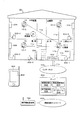
図1は住宅等に設置された警報システムと家電機器の消費電力等を管理する機器管理システムを連携させる場合の本発明による連携システムの概略構成を示した説明図である。 FIG. 1 is an explanatory diagram showing a schematic configuration of a linkage system according to the present invention in a case where an alarm system installed in a house or the like and a device management system for managing power consumption of household electrical appliances are linked.
図1の例にあっては、住宅24に設けられている台所、居間、子供部屋、主寝室のそれぞれの警戒エリア(監視領域)に、火災を検知して連動警報する無線連動型の住警器(住宅用火災警報器)10−1〜10−4が設置され、警報システムを構築している。 In the example of FIG. 1, a wireless interlocking residence police that detects fire and interlocks alarms in the respective alert areas (monitoring areas) of the kitchen, living room, children's room, and master bedroom provided in the house 24. Units (fire alarms for houses) 10-1 to 10-4 are installed to construct an alarm system.
以下、住警器10−1〜10−4をそれぞれ区別せず総称する場合は住警器10という。なお、住警器は階段室などにも設置されるが、図示を省略する。 Hereinafter, the housing alarm devices 10-1 to 10-4 are collectively referred to as the housing alarm device 10 without being distinguished from each other. In addition, although a residence guard is also installed in a staircase or the like, the illustration is omitted.
また、警報システム内で警報器同士が連動する場合を「連動」といい、また異なるシステム同士の機器が連動する場合を「連携」という。 In addition, a case where alarm devices are linked in the alarm system is called “linkage”, and a case where devices of different systems are linked is called “linkage”.
また、警報システム内で警報器同士が送受信する信号を「連動信号」といい、異なるシステムの機器同士で送受信する信号を「連携連動信号」という。前者の連動信号には、火災連動信号、火災復旧連動信号、警報停止連動信号、障害連動信号、非常通報連動信号があり、後者の連携連動信号には火災連携連動信号、火災復旧連携連動信号、警報停止連携連動信号、障害連携連動信号及び非常通報連携連動がある。 In addition, a signal transmitted and received between alarm devices in the alarm system is referred to as a “linked signal”, and a signal transmitted and received between devices in different systems is referred to as a “linked signal”. The former interlock signal includes a fire interlock signal, a fire recovery interlock signal, an alarm stop interlock signal, a failure interlock signal, and an emergency alert interlock signal. There is an alarm stop linkage signal, a failure linkage linkage signal, and an emergency call linkage linkage.
住警器10は、連動信号を無線により相互に送受信する機能を備え、住宅各所の、それぞれ対応する監視領域について火災発生の有無を監視している。いま住宅24の台所で万一、火災が発生したとすると、住警器10−1が火災を検知して警報を開始する。この火災を検知して警報を開始することを、住警器における「発報」という。 The home alarm device 10 has a function of wirelessly transmitting and receiving interlocking signals to each other, and monitors the presence or absence of a fire in the corresponding monitoring area in each place of the house. If a fire has occurred in the kitchen of the house 24, the home alarm device 10-1 detects the fire and starts an alarm. Detecting this fire and initiating an alarm is referred to as “reporting” at the home alarm.
住警器10−1が発報するとき、住警器10−1は連動元として機能し、連動先となる他の住警器10−2〜10−4に対し、火災連動信号を無線送信する。他の住警器10−2〜10−4は、連動元の住警器10−1からの火災連動信号を有効受信した場合に、警報音と警報表示により連動先としての警報動作を行う。 When the home alarm device 10-1 issues a report, the home alarm device 10-1 functions as an interlocking source, and wirelessly transmits a fire interlocking signal to the other interlocking devices 10-2 to 10-4 as the interlocking destination. To do. When the other home alarm devices 10-2 to 10-4 have received the fire interlock signal from the home alarm device 10-1 of the interlocking source effectively, the alarm operation as the interlocking destination is performed by the alarm sound and the alarm display.
ここで、住警器10は、受信した連動信号に含まれるグループ符号がメモリに登録しているグループ符号に一致し、且つ信号内容を正常認識したときに、この連動信号を有効受信したことを検知するようにしている。さらに、連動信号を有効受信した住警器10は必要に応じて連動信号の中継送信を行う。グループ符号は警報システム毎に固有の符号として設定されており、各住警器はこの符号によって自己の属する警報システムに関連する連動信号のみを識別処理することができる。 Here, when the group code included in the received interlocking signal matches the group code registered in the memory and the signal content is normally recognized, the resident alarm 10 confirms that the interlocking signal has been effectively received. I try to detect it. Furthermore, the resident guard 10 that has effectively received the interlocking signal relays the interlocking signal as necessary. The group code is set as a unique code for each alarm system, and each residential alarm can identify and process only the interlocking signal related to the alarm system to which it belongs.
連動元となった住警器10−1の警報動作としては、例えば「ウーウー 火災警報器が作動しました 確認してください」といった音声メッセージによる火災警報音を出力する。一方、連動先の住警器10−2〜10−4にあっては、「ウーウー 別の火災警報器が作動しました 確認してください」といった音声メッセージによる火災警報音を出力する。 As an alarm operation of the home alarm device 10-1 that is the interlock source, for example, a fire alarm sound is output by a voice message such as “Please confirm that the Woo Woo fire alarm has been activated”. On the other hand, the interlocking home alarm devices 10-2 to 10-4 output a fire alarm sound with a voice message such as “Please confirm that another fire alarm device has been activated”.
また連動元となった住警器10−1の火災警報に伴う警報表示としては、例えばLEDを点灯する。一方、連動先の住警器10−2〜10−4にあっては、LEDを点滅する。これによって、連動元警報と連動先警報におけるLEDによる警報表示を区別できるようにしている。 Moreover, as an alarm display accompanying the fire alarm of the residence police device 10-1 which became the interlocking source, for example, an LED is lit. On the other hand, in the interlocking residence police 10-2 to 10-4, the LED blinks. As a result, the alarm display by the LED in the interlock source alarm and the interlock destination alarm can be distinguished.
住警器10は、自己が火災を検知した場合、所定の第1通信プロトコルに従った火災連動信号を他の住警器に送信する。また住警器10は、他の住警器から送信された火災連動信号を受信する。 When the home alarm device 10 detects a fire, the home alarm device 10 transmits a fire-linked signal according to a predetermined first communication protocol to the other home alarm devices. Moreover, the residence guard 10 receives a fire interlocking signal transmitted from another residence guard.
住警器10における第1通信プロトコルによる送受信は、日本国内の場合には、例えば400MHz帯の特定小電力無線局の標準規格として知られたSTD−30(小電力セキュリティシステム無線局の無線設備標準規格)またはSTD−T67(特定小電力無線局テレメータ用、テレコントロール用及びデータ伝送用無線設備の標準規格)に準拠する。もちろん日本国内以外で使用する場合は、その地域の割当無線局の標準規格に準拠した内容を持つことになる。特定小電力無線局に準拠した住警器10の送信電力は、STD−30の場合は10mW以下であり、STD−T67の場合は10mW以下または1mW以下であり、見通し通信距離は概ね100メートル程度となる。
Home alarm that you only to 10 transmission and reception by the first communication protocol, in the case of Japan, for example, STD-30 is known as a standard for specified low power radio stations in 400MHz band (low-power security system radio station It conforms to STD-T67 (standard specification for radio equipment for specific low power radio station telemeter, telecontrol and data transmission). Of course, when used outside Japan, the content conforms to the standard of the assigned radio station in that region. The transmission power of the residential guard 10 compliant with the specified low power radio station is 10 mW or less for STD-30, 10 mW or less or 1 mW or less for STD-T67, and the line-of-sight communication distance is approximately 100 meters. It becomes.
更に住警器10には人感センサ15が設けられ、人体を検知して人検知信号を出力する。人感センサ15からの人検知信号は在宅情報の生成に利用される。
Furthermore, a
図2は本発明で使用する無線連動型の煙式住警器の外観を示した説明図であり、図2(A)に正面図を、図2(B)に側面図を示している。なお、取付フック24を設けているほうを上側とする。 2A and 2B are explanatory views showing the appearance of a wireless interlocking smoke-type home alarm used in the present invention. FIG. 2A shows a front view and FIG. 2B shows a side view. The side provided with the mounting hook 24 is the upper side.
図2において、本実施形態の住警器10の筐体はカバー12と本体14で構成されている。カバー12の中央には突出部を設け、突出部の周囲に複数の煙流入口を開口し、その内部には検煙部16が配置され、火災に伴う煙が検煙部16に流入して所定濃度に達したときに後述する警報制御部で火災を検知するようにしている。検煙部16としては、例えば公知の散乱光式検煙機構が適用できる。
In FIG. 2, the housing of the residential alarm 10 according to the present embodiment includes a
カバー12の左下側には音響孔18が設けられ、この背後にブザーやスピーカを内蔵し、警報音や音声メッセージを出力できるようにしている。カバー12の下側には警報停止スイッチ20が設けられている。
An acoustic hole 18 is provided on the lower left side of the
警報停止スイッチ20は、半透明部材で形成されたスイッチカバーを押圧操作すると、内蔵のプッシュスイッチ(図示せず)が押圧されるようになっている。スイッチカバー内部のプッシュスイッチ近傍には、警報等の表示を行うLED22が配置されている。
The
警報停止スイッチ20は外部から住警器10の機能の自己点検実施を指示する点検スイッチとしての機能を兼ねている。例えば、火災警報出力中に警報停止スイッチ20が操作されると火災警報を停止し、通常状態で警報停止スイッチ20が操作されると所定の機能について自己点検を実施し、LED22やスピーカなどによりて結果を報知する。ここで通常状態とは、少なくとも火災警報出力中または障害警報出力中でない状態を指す。
The
カバー12の右上には人感センサ15が設けられている。人感センサ15は人体から発する赤外線を検知して人検知信号を出力し、人感センサ15は住警器15を部屋の壁面上部に取付けた場合に斜め下向きとなる指向方向を持つように設けられている。
A
また本体14の裏側上部にはその略中央部に挿通孔を有する取付フック24が設けられており、設置する部屋の壁にビスなどをねじ込み、この取付フック24の挿通孔にビスを通して引っかけることで、壁面に住警器10を所謂壁掛け状に固定設置することができる。 Further, a mounting hook 24 having an insertion hole in the substantially central portion thereof is provided at the upper part on the back side of the main body 14, and a screw or the like is screwed into the wall of the room to be installed and hooked through the insertion hole of the mounting hook 24. The residential alarm 10 can be fixedly installed on the wall surface in a so-called wall-hanging manner.
再び図1を参照するに、子供部屋には発信機100が設けられている。発信機100には非常押釦スイッチが設けられており、非常押釦スイッチを操作すると第1通信プロトコルに従った非常通報連動信号が住警器10−1〜10−4に送信され、住警器10−1〜10−4から「ウーウー 発信機が作動しました 確認してください」といった非常通報警報音を出力する。
Referring to FIG. 1 again, a
図3は本発明の警報システムで使用する無線式連動型の発信機の外観を示した説明図であり、図3(A)に正面図を、図3(B)に側面図を示している。なお、取付フック115を設けているほうを上側とする。
FIG. 3 is an explanatory view showing the appearance of a wireless interlocking transmitter used in the alarm system of the present invention, with FIG. 3 (A) showing a front view and FIG. 3 (B) showing a side view. . The side provided with the
図3において、本実施形態の発信機100の筐体はカバー112と本体114で構成されている。カバー112の中央には、非常押釦スイッチ116が設けられる。非常押釦スイッチ116は、半透明部材で形成されたスイッチカバーと、スイッチカバーの内部に配置されたプッシュスイッチ(図示せず)とで構成されている。
In FIG. 3, the casing of the
スイッチカバー内部のプッシュスイッチ近傍には、点線で示すように発信機灯として機能するLED118が配置されており、作動光が非常押釦スイッチ116の半透明スイッチカバーを透過してLED118の作動状態が外部から視認できるようにしている。
An
非常押釦スイッチ116を押し込み操作するとLED118が点滅又は明滅し、非常通報信号の送信完了が確認されると点灯に切り替わり、所定時間後に消灯する。
When the emergency
非常押釦スイッチ116は警報停止スイッチとしての機能を兼ねている。例えば、火災警報出力中に非常押釦スイッチ116が操作されると火災警報を停止する。
The emergency
非常押釦スイッチ116の左下側にはスリット状の音響穴120が複数設けられ、この背後にブザーやスピーカを内蔵し、警報音や音声メッセージを出力できるようにしている。
A plurality of slit-like
本体114の裏側上部には、略中央部に挿通孔を有する取付フック115が設けられており、設置する部屋の壁面等にビスなどをねじ込み、この取付フック115の挿通孔にビスを通して引っかけることで、壁面の手の届く位置に発信機100を所謂壁掛け状に固定設置することができる。
A mounting
再び図1を参照するに、住宅24には家電機器の消費電力を管理する機器管理システムを構築するための機器として、電源コンセント装置200−1〜200−5とインターネット400に接続するためのネットワークアダプタとして機能するゲートウェイ装置300が設置されている。ゲートウェイ装置300によるインターネット400との接続は、周知のようにインターネットサービスプロバイダ(ISP)の保有するサーバによる接続サービスを利用する。
Network to connect Referring again to FIG. 1, as a device for the housing 24 to construct a device management system for managing power consumption of a household electrical appliance, the electrical outlet device 200-1~ 200 -5 and the Internet 400 A
電源コンセント装置200−1には冷蔵庫230が接続され、電源コンセント装置200−2にはテレビ232が接続され、電源コンセント装置200−3〜200−5にはエアコン234が接続されている。以下、電源コンセント装置200−1〜200−5をそれぞれ区別せず総称する場合は電源コンセント装置200という。
The power outlet 200-1 is connected
電源コンセント装置200には消費電力を検知するセンサと無線送受信チップが設けられており、家電機器のプラグをコンセントに接続して電源を供給すると、周期的に消費電力が測定され、電力検知信号が無線送受信チップから所定の第2無線通信プロトコルに従ってゲートウェイ装置300に送信される。
The power outlet device 200 is provided with a sensor for detecting power consumption and a wireless transmission / reception chip. When power is supplied by connecting a plug of a household appliance to an outlet, the power consumption is periodically measured, and a power detection signal is generated. The data is transmitted from the wireless transmission / reception chip to the
ゲートウェイ装置300は電源コンセント装置200から第2無線通信プロトコルに従って送信された電力検知信号を、TCP/IPとして知られたインターネット通信プロトコルに変換し、インターネット400を介してネットワーク上のサーバとなる管理用のサーバ500に電力検知信号を送信する。
The
サーバ500にはアプリケーションとして機器管理部502の機能が設けられており、電源コンセント装置200から送られてきた電力検知信号に基づき例えば対象機器の単位時間当りの消費電力量や期間を指定した総消費電力量等を求めている。サーバ500は、利用者端末となる例えば携帯電話800に対し携帯電話ネットワーク600及び携帯電話基地局700を介して閲覧ページ情報等を送信して表示させ、住宅24の家電機器の消費電力情報を利用者が閲覧できるようにしている。
The
このような電力管理サービスを提供するため、サーバ500は例えばサービス加入者の保有する携帯電話800の電話番号をインデックス(索引)として、加入者情報、消費電力情報等を格納したデータベース508を備えている。
In order to provide such a power management service, the
またサーバ500により提供される消費電力を管理するサービスは、携帯電話800の加入者に提供される有料サービスとなる。
A service for managing power consumption provided by the
なお、本実施形態における第1無線通信プロトコルと第2無線通信プログラム取るは、請求項の第1通信プロトコルと第2通信プロトコルに対応する。 Note that taking the first wireless communication protocol and the second wireless communication program in the present embodiment corresponds to the first communication protocol and the second communication protocol in the claims.
住宅24に設置している電源コンセント装置200及びゲートウェイ装置300に内蔵した無線送受信チップにより第2無線通信プロトコルに従って行われる信号送受信としては、例えばRFID(Radio Frequency IDentification「電波による個体識別」の略)に割当てられた900MHzの周波数、即ち950〜957MHzを使用したZ−Wave(R)やZigBee(R)として知られたセンサネットワーク用の近距離無線通信プロトコルを使用する。
As signal transmission / reception performed according to the second wireless communication protocol by the wireless transmission / reception chip built in the power outlet apparatus 200 and the
特にZ−Wave(R)は、ホームオートメーション向けに開発された無線通信プロトコルであり、知能型メッシュネットワークトポロジーを使用しており、マスタノードを持たず、例えばノードA,B,Cが配置されている場合、ノードAとノードCがお互いに通信できない距離にあっても、その間に位置するノードBの中継機能によりノードAからノードCに通信することかでき、本実施形態の機器管理システムの第2無線通信プロトコルとして好適である。 In particular, Z-Wave (R) is a wireless communication protocol developed for home automation, uses an intelligent mesh network topology, does not have a master node, for example, nodes A, B, and C are arranged. If the node A and the node C are at a distance that cannot communicate with each other, the relay function of the node B located between them can communicate from the node A to the node C. It is suitable as a two-wireless communication protocol.
また家電向けの短距離無線通信規格として提供されているZigBee(R)も使用可能である。ZigBee(R)にあっては1台のコーディネータとして機能するノードと、ルータとして機能する複数ノードを配置することで、コーディネータを中心にスター型のネットワークとボロジーを構築でき、またルータとして機能するノードのみの場合はピア・ツー・ピア型(pear to Pear)のネットワークトポロジーを構築できる。 ZigBee (R) provided as a short-range wireless communication standard for home appliances can also be used. In ZigBee (R), a node that functions as a coordinator and a plurality of nodes that function as routers can be used to construct a star-type network and a topology based on the coordinator. In the case of only, a peer-to-peer network topology can be constructed.
Z−Wave(R)やZigBee(R)といった900MHzの短距離無線通信は、送信電力を住警器10の特定小電力無線局と同様に1mW以下としており、見通し通信距離は概ね数十メートル程度であり、400MHz帯を使用した住警器10の見通し通信距離となる概ね100メートル程度に比べ、短くなっている。
Z-Wave 900 MHz short-range wireless communications such as (R) or ZigBee (R) is a 1mW or less similar to the specified low power radio stations in home alarm 10 the transmission power, the communication distance outlook is generally several tens of meters a degree, compared to approximately about 100 meters the sight communication distance of home alarm 10 using the 400MHz band is shorter.
このような住警器10を配置した警報システムと電源コンセント装置200とゲートウェイ装置300を含む機器管理システムを連携させるため、本発明にあっては、住警器10の内の少なくとも1台、例えばゲートウェイ装置300と相互に通信可能な距離となる同じ台所に設置され、相互に通信可能距離となる住警器10−1に、電源コンセント装置200及びゲートウェイ装置300に内蔵したと同じ第2無線通信プロトコルに従って通信動作する無線送受信チップを例えば追加的に設ける。
In order to link an alarm system in which such a home alarm device 10 is arranged with a device management system including a power outlet device 200 and a
ここで、第2無線通信プロトコルに従って連携連動信号を送受信する無線送受信チップは、ゲートウェイ装置300との通信可能距離に設置している住警器10−1のみならず、他の住警器10−2〜10−4の全てに設けるようにしても良い。
Here, the wireless transmission / reception chip that transmits and receives the cooperation interlocking signal according to the second wireless communication protocol is not limited to the residential alarm device 10-1 installed at a communicable distance with the
或いは、住警器には所定の第1通信プロトコルのみに従った送受信機能を設け、第1通信プロトコルとインターネットプロトコルの相互変換機能をゲートウェイ300側に設けても良い。更に或いは、この所定の第1通信プロトコルと所定の第2通信プロトコルの相互変換機能を備えた変換アダプタを住警器10とゲートウェイ300の間に介在させるようにしても良い。このようにすれば、少なくとも住警器10は台に通信プロトコルのための無線送受信チップ等を備える必要が無く、従来通りの通信機能を備えるものを使用することができる。また、ゲートウェイ300に第1通信プロトコルとインターネットプロトコルの変換機能を設ける場合には、第2通信プロトコルによる通信を行うことなく連携動作させることができる。
Alternatively, the home alarm may be provided with a transmission / reception function according to only a predetermined first communication protocol, and a mutual conversion function between the first communication protocol and the Internet protocol may be provided on the
また機器管理システムと連携させるため、発信機100にも電源コンセント装置200及びゲートウェイ装置300に内蔵したと同じ第2無線通信プロトコルに従って動作する無線送受信チップを設ける。
In order to link with the device management system, the
このため例えば住警器10−1自身で火災を検知した場合、他の住警器10−2〜10−4に対し第1無線通信プロトコルに従った火災連動信号を送信して連動警報を行わせると共に、ゲートウェイ装置300に第2無線通信プロトコルに従って火災連携連動信号を無線送信し、ゲートウェイ装置300ではこれを受信してTCP/IPとして知られたインターネット通信プロトコルに変換し、インターネット400を経由湯してIPアドレスにより宛先指定したてサーバ500に送信する。これを受信したサーバ500はアプリケーションとして設けた警報器管理部504の機能により受信した火災連携連動信号を処理し、処理結果を携帯電話ネットワーク600及び携帯電話基地局700を介して利用者の携帯電話800に伝送し、携帯電話800から火災警報を出力させる。携帯電話800からの火災警報出力は、表示画面出力やスピーカからの発音出力等、適宜の形態で行わせることができる。
For this reason, for example, when the fire is detected by the home alarm device 10-1 itself, a fire interlock signal according to the first wireless communication protocol is transmitted to the other home alarm devices 10-2 to 10-4 to perform the interlock alarm. In addition, a fire cooperation interlocking signal is wirelessly transmitted to the
また住警器10−1で火災を検知して警報した後に、火災復旧または住警器10−1に設けた操作部の警報停止操作を検知した場合、当該住警器10−1は、住警器10−2〜10−4に対し所定の第1プロトコルに従い住戸内の火災復旧連動信号または警報停止連動信号を送信すると共に、ゲートウェイ装置300に対し所定の第2無線通信プロトコルに従った火災復旧連携連動信号また警報停止連携連動信号を送信し、これを受信したゲートウェイ装置300は、TCP/IPとして知られたインターネット通信プロトコルに変換し、インターネット400を経由してIPアドレスにより宛先指定したてサーバ500に送信する。これを受信したサーバ500は警報器管理部504の機能により受信した災復旧連携連動信号また警報停止連携連動信号を処理し、処理結果を携帯電話ネットワーク600及び携帯電話基地局700経由で携帯電話800へ送信し、携帯電話800の警報画面802に警報停止や火災復旧を表示させて火災警報を解除させる。携帯電話800での火災警報解除動作は、火災警報出力同様に解除の旨を出力するか、或いは単に火災警報出力を停止する等、適宜の動作とすることができる。なお、住警器10−1は火災や火災復旧、警報停止操作を検知した場合には、第2無線通信プロトコルによるゲートウェイ装置300への火災連動信号送信とあわせて、第1無線通信プロトコルに従って他の住警器10−2〜10−4に対しても火災連動信号を送信する。
In addition, when a fire is detected and alarmed by the home alarm device 10-1, when the fire recovery or alarm stop operation of the operation unit provided in the home alarm device 10-1 is detected, the home alarm device 10-1 A fire recovery interlock signal or an alarm stop interlock signal in the dwelling unit is transmitted to the alarm devices 10-2 to 10-4 according to a predetermined first protocol, and a fire according to a predetermined second wireless communication protocol is transmitted to the
また住警器10−1が他の住警器からの第1無線通信プロトコルによる火災連動信号受信を検知してこの火災連動信号内容を第2無線通信プロトコルに従ってゲートウェイ装置300へ送信した後に、他の住警器(例えば火災を検知した連動元の住警器)から火災復旧連動信号または警報停止連動信号の受信を検知した場合にも、同様に、第2無線通信プロトコルに従った火災復旧連動信号または警報停止連動信号を、ゲートウェイ装置300を経由してサーバ500に送り、サーバ500は警報器管理部504での処理結果を、携帯電話ネットワーク600及び携帯電話基地局700を介して携帯電話800へ送信し、上記同様にして携帯電話800の警報画面802に警報停止や火災復旧を表示させる等して火災警報を解除させる。
In addition, after the residence guard 10-1 detects the reception of the fire-linked signal from the other residence guard by the first wireless communication protocol and transmits the contents of the fire-linked signal to the
なお、住警器10−1は他の住警器から第1無線通信プロトコルにより送信される火災、火災復旧、警報停止操作を示す連動信号有効受信を検知した場合には、第2無線通信プロトコルによるゲートウェイ装置300へ対応する連動信号内容を送信することとあわせて、必要に応じ、第1無線通信プロトコルにより別の住警器に対して対応連動信号を中継送信する。
In addition, when the home alarm device 10-1 detects the interlocked signal effective reception indicating the fire, the fire recovery, and the alarm stop operation transmitted from the other home alarm device by the first wireless communication protocol, the second wireless communication protocol In addition to transmitting the corresponding interlocking signal content to the
また、第1無線通信プロトコルによる住警器10相互間の連動信号や中継連動信号、住警器10−1からゲートウェイ装置300への連動信号、ゲートウェイ装置300からサーバ500、携帯電話基地局700、携帯電話800への信号は、説明の簡単のため通信プロトコル以外には特に区別していないが、一連の連動に伴う信号の内容(例えばひとつの火災検知に伴う火災発生の旨)につき、各通信区間で必要となる情報(例えばその火災発生の旨等)が各通信規格やプロトコルに適合する形式で含まれていれば必ずしも同一の内容である必要は無く、それぞれに適宜異なる内容のものであっても良いことはもちろんである。これは、後述のように伝送方向が逆向きとなる場合、即ち携帯電話800側から警報システム側への伝送を行う場合にも同様である。
In addition, the interlocking signal and relay interlocking signal between the residential alarms 10 according to the first wireless communication protocol, the interlocking signal from the residential alarm 10-1 to the
また本実施形態における第1無線通信プロトコルと第2無線通信プロトコルは、請求項の第1通信プロトコルと第2通信プロトコルに対応する。 The first wireless communication protocol and the second wireless communication protocol in the present embodiment correspond to the first communication protocol and the second communication protocol in the claims.
一方、発信機100で非常通報スイッチを操作した場合には第1無線通信プロトコルに従った非常通報連動信号の住警器10−1〜10−4に対する送信に加え、第2無線通信プロトコルに従った非常通報連動信号をゲートウェイ装置300に無線送信し、ゲートウェイ装置300でインターネット通信プロトコルに変換してサーバ500に送信し、警報器管理部504で処理後、処理結果を携帯電話ネットワーク600及び携帯電話基地局700を介して利用者の携帯電話800に伝送して非常通報警報を出力させる。
On the other hand, when the emergency call switch is operated by the
サーバ500に設けた在宅管理部506は、携帯電話800からの在宅確認要求信号の受信を検知した場合、インターネット400、ゲートウェイ装置300を経由して住警器10−1〜10−4に設けた人感センサ15の検知信号を取得して在宅情報を生成し、生成した在宅情報を携帯電話800に表示させる。
When the home management unit 506 provided in the
ここで、図1における各プロトコルによる通信経路を整理すると、例えば台所に設置した住警器10−1を中心に見ると、住警器10−1と他の住警器10−2〜10−4の間は第1無線通信プロトコル経路11aとなり、住警器10−1とゲートウェイ装置300との間は第2無線通信プロトコル経路11bとなり、電源コンセント装置200−1とゲートウェイ装置300との間は第2無線通信プロトコル経路11bとなり、更にゲートウェイ装置300とインターネット400を経由したサーバ500との間はインターネット通信プロトコル経路11cとなる。なお図示を省略しているが、発信機100と住警器10−1〜10−4の間は第1無線通信プロトコル経路11aとなり、発信機100とゲートウェイ装置300との間は第2無線通信プロトコル経路11bとなる。また住警器10−1〜10−4及び発信機100の間には直接または中継による第1無線通信プロトコル経路11aが形成される。
Here, when the communication paths according to the respective protocols in FIG. 1 are arranged, for example, when viewed mainly from the residential police 10-1 installed in the kitchen, the residential police 10-1 and the other residential police 10-2 to 10- 4 becomes the first wireless
図4は図1の携帯電話800に表示される在宅確認要求画面802の一例を示した説明図である。携帯電話800はタッチパネル付きのディスプレイを使用しており、在宅確認要求画面802には利用者に在宅確認要求操作の案内メッセージ803が表示され、各釦は透明なタッチパネルとなっていることから、起動釦804を操作するとサーバ500に対し在宅確認要求信号が送信され、在宅管理部506がインターネット400、ゲートウェイ装置300を経由して住警器10−1〜10−4に設けた人感センサ15の検知信号を取得して在宅情報を生成し、図5に一例として示す在宅情報画面810を携帯電話800に表示させる。
FIG. 4 is an explanatory view showing an example of a home
図5の在宅情報画面810は、時刻情報812に続いて在宅情報814として住宅24の部屋毎に分けて人感センサ15の人検知信号に基づき、在宅を示す「います」と、不在を示す「空き」を表示している。このような在宅確認機能により利用者は外出中など必要に応じて住宅24の様子を確認することができる。
The
なお、在宅情報の表示は、携帯電話800からの在宅確認要求以外に、住警器10の人感センサ15で不在状態から人を検知した場合に、ゲートウェイ装置300、インターネット400を介してサーバ500の在宅管理部506に人検知信号を送って携帯電話800に在宅情報を表示させても良い。
The display of the home information, in addition to home recognition request from the
またサーバ500の機器管理部502は、必要に応じてインターネット400、ゲートウェイ装置300を経由して住警器10に設けた人感センサ15の人検知信号を取得し、例えば不在を検知した場合に家電機器の電源オフ制御などの制御処理を行わせることもができる。
In addition, the device management unit 502 of the
図6は図1の携帯電話800に表示される火災警報画面816の一例を示した説明図である。図6において、携帯電話800はサーバ500で住警器10からの火災連動信号を受信した場合に警報画面816を表示させると共に火災警報音を出力させる。警報画面816には例えば「台所の火災警報器が作動しました 確認してください」といった警報メッセージが設置場所と共に表示される。
FIG. 6 is an explanatory diagram showing an example of a
また警報メッセージの下には操作部位として在宅確認釦818、自宅自動ダイヤル釦820、119自動ダイヤル釦822、110自動ダイヤル釦824及び警報停止釦826が表示され、必要な操作を行なうことができる。
Under the alarm message, a
例えば在宅確認釦818を操作すると在宅確認要求信号が携帯電話基地局700及び携帯電話ネットワーク600を介してサーバ500に送信され、図5に示した在宅情報画面810が表示され、台所の住警器10−1が作動している住宅24に人が居るか否かを確認でき、もし人がいる場合には自宅自動ダイヤル釦820を操作して連絡をとり、更に状況に応じて119自動ダイヤル釦706、110自動ダイヤル釦708を操作することで、消防機関や警察機関との通話接続を行うことができる。
For example, when the
このように火災警報が出力された場合にリアルタイムで取得表示できる在宅情報は、火災警報に対する迅速な判断対応をとる上で極めて重要な情報となる。 Home information that can be acquired and displayed in real time when a fire alarm is output in this manner is extremely important information for taking a quick judgment response to the fire alarm.
更に、在宅情報や自宅電話などにより状況確認後に住宅24での火災警報を停止する場合には警報停止釦710を操作する。警報停止釦710を操作すると、警報停止連携連動信号が携帯電話基地局700、携帯電話ネットワーク600、サーバ500、ゲートウェイ装置300を介して火災を検知していた住警器10−1へ第2無線通信プロトコルに従って送られ、連動元火災警報を停止させる。また住警器10−1はゲートウェイ装置300からの警報停止連携連動信号を受信すると、他の住警器10−2〜10−4に対して、第1無線通信プロトコルに従って警報停止連動信号を送信し、連動先火災警報を停止させることができる。
Further, when the fire alarm in the house 24 is stopped after the situation is confirmed by home information or a home phone, the alarm stop button 710 is operated. When the alarm stop button 710 is operated, the alarm stop cooperation interlocking signal is second wirelessly transmitted to the home alarm device 10-1 that has detected the fire via the mobile
図6に示すような火災警報画面816を携帯電話800に表示して火災警報を出力するため、図1のサーバ500の警報器管理部504は、加入者のサービス申し込みに基づいて、データベース508に警報器管理に必要な情報として、住宅24に設置している住警器10−1〜10−4の識別符号例えばシリアル番号等に対応して設置場所を示す情報を予め登録している。
In order to display the
このためゲートウェイ装置300を経由して火災連動信号の有効受信をサーバ500の警報器管理部504で検知した場合、住警器識別符号によりデータベース508を参照して設置場所の情報を取得し、図6に示したように、住警器の設置場所を示す火災警報表示を可能とする。
For this reason, when the
もちろん、このようにサーバ500に設けたデータベースや警報器管理部504が持つ機能構成の任意の一部または全部を携帯電話800側に設けても良い。また、データベースをサーバ500側に設ける場合には、上記住警器識別符号等の登録を、携帯電話800や別のパーソナルコンピュータ等からインターネット400経由でサーバ500のユーザ用ホームページ等へアクセスして行うようにしても良い。
Of course, any part or all of the functional configuration of the database and the
図7は図1の携帯電話800に表示される非常通報警報画面828の一例を示した説明図である。図7において、携帯電話800はサーバ500から携帯電話ネットワーク600及び携帯電話基地局700を介して発信機100からの非常通報連動信号受信を検知した場合に、非常通報警報画面828を表示させると共に警報音を出力させる。非常通報警報画面828には例えば「発信機が作動しました 確認してください」といった警報メッセージが表示される。
FIG. 7 is an explanatory diagram showing an example of an emergency
また警報メッセージの下には操作部位として、図6の火災警報画面816と同様、在宅確認釦818、自宅自動ダイヤル釦820、119自動ダイヤル釦822、110自動ダイヤル釦824及び警報停止釦826が表示され、各釦は透明なタッチパネルとなっていることから、必要な操作を行なうことができる。
Below the alarm message, as in the case of the
特に在宅確認釦818を操作すると在宅確認要求信号が携帯電話基地局700及び携帯電話ネットワーク600を介してサーバ500に送信され、これを受けたサーバ500で在宅情報が生成され、これに対応した在宅情報信号が携帯電話ネットワーク600及び携帯電話基地局700を介して送信され、これを携帯電話800で受信することで、図5に示した在宅情報画面810が表示される。この場合、台所と発信機100が操作されている子供部屋に人がいるといった在宅状況を確認でき、自宅自動ダイヤル釦820を操作して連絡をとり、更に状況に応じて119自動ダイヤル釦706、110自動ダイヤル釦708を操作することで、消防機関や警察機関との通話接続を行うことができる。
In particular, when the
このように非常通報警報が出力された場合にリアルタイムな在宅情報を連携して取得表示できることは、非常通報警報に対する迅速な判断対応をとる上で極めて重要となる。 In this way, when an emergency call alarm is output, it is extremely important to be able to obtain and display real-time home information in cooperation with each other in order to quickly determine and respond to the emergency call alarm.
更に、状況を確認して住宅24での非常通報警報を停止させる場合には警報停止釦710を操作する。警報停止釦710を操作すると、警報停止連携連動信号が携帯電話基地局700、携帯電話ネットワーク600、サーバ500、ゲートウェイ装置300を介して非常通報警報を出力している住警器10−1へ送られ、非常通報警報を停止させる。
Furthermore, when the situation is confirmed and the emergency call alarm in the house 24 is stopped, the alarm stop button 710 is operated. When the alarm stop button 710 is operated, an alarm stop cooperation interlocking signal is sent to the residential alarm device 10-1 that outputs an emergency call alarm via the mobile
また住警器10−1はゲートウェイ装置300からの警報停止連携連動信号を受信すると、他の住警器10−2〜10−4に対して、第1無線通信プロトコルに従って警報停止連動信号を送信させ、非常通報警報を停止させることができる。
In addition, when the home alarm device 10-1 receives the alarm stop cooperation interlocking signal from the
図8は本発明で用いる住警器の要部構成を示したブロック図である。これは一例であり、各機能の分離、統合は任意に行うことができる。また各機能のそれぞれの一部または全部は、ソフトウェア(プログラム)によって実行されるものであっても、ハードウェアによって実行されるものであっても良い。また図4では、台所に設置した住警器10−1について示しているが、本実施形態の場合は他の住警器10−2〜10−4についても同様の構成となる。 FIG. 8 is a block diagram showing the configuration of the main part of the house alarm used in the present invention. This is an example, and the separation and integration of each function can be performed arbitrarily. Each part or all of each function may be executed by software (program) or may be executed by hardware. Moreover, in FIG. 4, although it has shown about the residence guard 10-1 installed in the kitchen, in the case of this embodiment, it becomes the same structure also about other residence guards 10-2 to 10-4.
なお、第2無線通信部34(これまで説明した「無線送受信チップ」に相当する)を住警器10−1のみに設ける場合には、他の住警器10−2〜10−4はこれを備えていない。 In addition, when providing the 2nd radio | wireless communication part 34 (equivalent to the "radio | wireless transmission / reception chip | tip" demonstrated so far) only in the residence guard 10-1, other residence guards 10-2 to 10-4 are this. Not equipped.
図8において、住警器10−1はワンチップCPUとして知られたプロセッサ28を備え、プロセッサ28に対してはアンテナ32を接続した第1無線通信プロトコルの送受信を行う第1無線通信部30、アンテナ36を接続した第2無線通信プロトコルの送受信を行う第2無線通信部34、センサ部38、報知部40、操作部42、メモリ44が設けられ、電池電源46は必要各部に電源を供給している。なお、本実施形態における第1無線通信部と第2無線通信部は、請求項の第1通信部と第2通信部に対応する。
In FIG. 8, the home alarm device 10-1 includes a processor 28 known as a one-chip CPU, and a first wireless communication unit 30 that performs transmission / reception of a first wireless communication protocol to which an antenna 32 is connected to the processor 28, the second wireless communication unit 34 performs transmission and reception of the second wireless communication protocol connected to the
第1無線通信部30にはアンテナ32を接続した第1送信回路48と第1受信回路50が設けられている。第1無線通信部30はこのアンテナ32を介して他の住警器10−2〜10−4との間で、例えば400MHz帯の特定小電力無線局の標準規格に準拠した第1無線通信プロトコルに従って火災、火災復旧、警報停止、障害などの各種の連動信号を送受信する。
The first wireless communication unit 30 first transmitting circuit 48 and the first receiver circuit 50 connected to the antenna 32 is found provided. The first wireless communication unit 30 communicates with the other residential alarm devices 10-2 to 10-4 via the antenna 32, for example, a first wireless communication protocol that complies with the standard of a specific low power wireless station in the 400 MHz band. In accordance with the above, various interlocking signals such as fire, fire recovery, alarm stop, and failure are transmitted and received.
第1無線通信部30の第1送信回路48における第1無線通信プロトコルによる連動信号の送信は、所定時間T1、例えばT1=3秒に亘り連動信号を送信する動作を、所定時間T2、例えばT2=2秒の休止時間を空けて例えば4回繰り返している。このT1=3秒送信、T=2秒休止は特定小電力無線局の標準規格に準拠したものである。またT1=3秒の送信動作は、その内の最初から例えば2.8秒はダミー信号の送信であり、残り0.2秒の時間に連動信号の反復送信を行う。 The transmission of the interlocking signal by the first wireless communication protocol in the first transmission circuit 48 of the first wireless communication unit 30 is the operation of transmitting the interlocking signal for a predetermined time T1, for example, T1 = 3 seconds, and the predetermined time T2, for example, T2 For example, four times with a pause of 2 seconds. This T1 = 3-second transmission and T = 2-second pause comply with the standard of a specific low-power radio station. Further, in the transmission operation of T1 = 3 seconds, for example, 2.8 seconds from the beginning of the transmission operation is a dummy signal transmission, and the interlocking signal is repeatedly transmitted in the remaining 0.2 seconds.
また、第1無線通信部30の第1受信回路50における第1無線通信プロトコルによる受信は、他の住警器10−2〜10−4からの連動信号を間欠受信して解読する。間欠受信は、所定周期T3毎に、例えばT3=7秒毎に受信可能時間T4、例えばT4=100ミリ秒のあいだ受信動作を繰り返しており、受信可能時間T4の間に送信ダミー信号をキャリアセンスにより検知すると所定時間のあいだ連続受信に切替えてダミー信号に続く連動信号を受信して解読する。 In addition, the reception by the first wireless communication protocol in the first receiving circuit 50 of the first wireless communication unit 30 is intermittently received and decoded by interlocking signals from the other mortgages 10-2 to 10-4. In the intermittent reception, the reception operation is repeated for a predetermined period T3, for example, every T3 = 7 seconds, for a receivable time T4, for example, T4 = 100 milliseconds, and during the receivable time T4, the transmission dummy signal is carrier sensed. When the signal is detected, the reception is switched to continuous reception for a predetermined time, and the interlocking signal following the dummy signal is received and decoded.
なお、受信した信号はプロセッサ28に設けた警報制御部60で解読される。以下、この解読までを含めて受信と呼ぶことがある。また特に、解読の結果有効な信号と判定されることを区別して表す場合には有効受信と呼ぶ。後に説明する第2無線通信プロトコルによる受信についても同様にプロセッサ56で解読し、更に、発信機100、電源コンセント装置200、ゲートウェイ装置300の場合はプロセッサ156、228,328で解読する。
The received signal is decoded by an alarm control unit 60 provided in the processor 28. Hereinafter, the process up to this decoding may be referred to as reception. In particular, when the signal is determined to be valid as a result of decoding, it is called effective reception. Similarly, reception by the second wireless communication protocol, which will be described later, is decoded by the processor 56, and further, in the case of the
また第1無線通信プロトコルでは、住警器10−1自身が火災又は火災以外の事象を検知して連動信号を送信した場合、これを受信した他の住警器10−2〜10−4から連動信号を正常に受信したことを示す確認応答信号(以下「ACK信号」と云う)が有効受信されるか否か監視している。 Further, in the first wireless communication protocol, when the resident alarm 10-1 itself detects a fire or an event other than a fire and transmits an interlocking signal, from the other resident alarm devices 10-2 to 10-4 that have received this signal. It is monitored whether or not an acknowledgment signal (hereinafter referred to as “ACK signal”) indicating that the interlocking signal has been normally received is effectively received.
他の住警器のうち、ACK信号が受信されないものを検知した場合、住警器10−1はACK信号が受信された他の住警器に対し中継要求有り連動信号を送信し、中継要求有りの連動信号を受信した住警器からAKC信号未応答の住警器へ中継要求有りの連動信号を中継送信させる。中継要求有りの連動信号を中継受信したAKC信号未応答の住警器は中継要求有りの連動信号に対しACK信号を返信し、このACK信号が他の住警器の中継(返信の中継)を経て連動元の住警器10−1で受信される。これによってもACK信号が受信されない住警器がある場合には、通信障害等と判定し、所定の報知処理や連動処理、後述する連携処理等を行う。 When the other resident alarm is detected that the ACK signal is not received, the resident alarm 10-1 transmits the relay request presence interlock signal to the other resident alarm that has received the ACK signal, and the relay request. A relay signal with a relay request is relay-transmitted from the home alarm device that has received the interlock signal with the relay to the home alarm device that has not yet responded to the AKC signal. An ACK signal that has not received an AKC signal that has received a relay signal with a relay request returns an ACK signal in response to the relay signal with a relay request. After that, it is received by the interlocking home security device 10-1. Accordingly, if there is a residence guard that does not receive the ACK signal, it is determined as a communication failure or the like, and a predetermined notification process, a linkage process, a linkage process described later, and the like are performed.
第1無線通信プロトコルで送受信する信号は、連番、送信元識別符号、グループ符号及び事象符号を含むフォーマットで構成されている。連番は住警器毎に独立して生成される符号であり、連動信号の生成順或いは送信順番を示す連続番号である。これに基づいて例えば再中継の禁止等の管理を行うことができる。識別符号は各住警器を特定する例えば住警器のシリアル番号等であり、グループ符号は図1のように住宅24に設置した住警器10−1〜10−4で相互に連動を行う連動グループを構成するための符号である。 A signal transmitted and received by the first wireless communication protocol is configured in a format including a serial number, a transmission source identification code, a group code, and an event code. A serial number is a code | symbol produced | generated independently for every residence alarm device, and is a serial number which shows the production | generation order or transmission order of an interlocking signal. Based on this, management such as prohibition of re-relay can be performed. The identification code is, for example, the serial number of the home police device that identifies each home police device, and the group code is linked to each other by the home police devices 10-1 to 10-4 installed in the house 24 as shown in FIG. It is the code | symbol for comprising an interlocking group.
事象符号は、火災などの事象内容を表す符号であり、本実施形態にあっては4ビット符号を使用しており、例えば
0001=火災
0010=ACK
0011=警報停止
0100=復旧
0101=非常通報
0110=センサ障害
0111=ローバッテリー障害
としている。なお、先述した「中継要求有り」を示す符号はここでは省略しているが、ビット数を増やすことで、当然これも事象符号に追加することができる。また
中継送信する連動信号には、送信元(連動元)の住警器を示す識別符号と中継を行う住警器の識別符号の両方を付加する。更に、送信先を指定する識別符号を付加しても良い。
The event code is a code representing the content of an event such as a fire. In the present embodiment, a 4-bit code is used. For example, 0001 = fire 0010 = ACK
0011 = Alarm stop 0100 = Recovery 0101 = Emergency notification 0110 = Sensor failure 0111 = Low battery failure. Note that the above-described code indicating “relay request is present” is omitted here, but it can be added to the event code by increasing the number of bits. Moreover, both the identification code which shows the resident alarm of a transmission source (interlocking origin) and the identification code of the resident alarm which relays are added to the interlocking signal which carries out relay transmission. Further, an identification code for designating a transmission destination may be added.
先述の無線送受信チップに相当する第2無線通信部34にはアンテナ36を接続した第2送信回路48と第2受信回路50及びプロセッサ56が設けられている。第2無線通信部34はこのアンテナ36を介してゲートウェイ装置300との間で、例えば900MHz帯のZ−Wave(R)に準拠した第2無線通信プロトコルに従って火災、火災復旧、警報停止、障害など各種の連動信号を送受信する。
The second wireless communication unit 34 which corresponds to the aforementioned wireless transceiver chip second transmission circuit 48 and the second receiving circuit 50 and a processor 56 that connects the
センサ部38には、例えば散乱光式の煙検知原理によって煙を検出して煙濃度に応じた検出信号を出力する検煙部16を設けている。またセンサ部38に人体を検知する人感センサ15を設けている。
The sensor unit 38 is provided with a
報知部40には警報音等を出力する音響出力器であるスピーカ66と警報表示等を行うLED22が、図示しないそれぞれの駆動回路と共に設けられている。スピーカ66は、警報制御部60からの制御を受けて、住警器10−1がメモリ44等に保持している各種のデータ等に基づいて音声メッセージや警報音等を出力する。LED22は点滅や明滅、点灯などにより、火災などの異状その他事象を表示により報知する。
The notification unit 40 is provided with a speaker 66 that is an acoustic output device that outputs an alarm sound and the like, and an
操作部42には警報停止スイッチ20が設けられ、警報停止スイッチ20は前述したように点検スイッチとしての機能を兼ねている。
The operation unit 42 is provided with the
メモリ44には、連動信号の生成に使用する連番、識別符号、グループ符号が格納されている。 The memory 44 stores a serial number, an identification code, and a group code used for generating the interlocking signal.
電池電源46は、例えば所定セル数のリチウム電池やアルカリ乾電池を使用しており、必要各部へ電源を供給する。電池容量としては住警器10−1における回路部全体の低消費電力化により、例えば10年の寿命を保証している。 The battery power supply 46 uses, for example, a lithium battery or an alkaline battery having a predetermined number of cells, and supplies power to necessary parts. As a battery capacity, for example, a lifetime of 10 years is guaranteed by reducing the power consumption of the entire circuit unit in the residence guard 10-1.
プロセッサ28にはプログラムの実行により実現される機能として、警報制御部60、連携処理部62及び人感センサ処理部64の機能が設けられる。 The processor 28 is provided with functions of an alarm control unit 60, a cooperation processing unit 62, and a human sensor processing unit 64 as functions realized by executing the program.
警報制御部60は、センサ部38に設けた検煙部16からの煙検出信号に基づく火災の有無、操作部42による警報停止指示入力の有無や点検指示入力の有無、センサ部38に設けた検煙部16からの煙検出信号が低下して火災検知状態が解消される火災復旧の有無、センサ障害や故障、ローバッテリー障害有無等の事象を検知する。また警報制御部60は第1受信回路50を介して他の住警器10−2〜10−4からの連動信号の解読結果として得られた連動信号有効受信の有無およびその連動内容を検知する。
The alarm control unit 60 is provided in the sensor unit 38 based on the presence / absence of a fire based on the smoke detection signal from the
また警報制御部60は、センサ部38に設けた検煙部16の煙検出信号に基づき火災(有り)を検知した場合に、報知部40に対しスピーカ66から連動元を示す警報動作として火災警報音例えば「ウーウー 火事です 火事です 確認して下さい」の音声メッセージを繰り返し出力させる制御を行うと共に、LED22を点灯させて連動元を示す火災警報表示を行わせる制御を行い、また、第1無線通信部30の第1送信回路48に対して第1無線通信プロトコルに従った火災連動信号をアンテナ32から他の住警器10−2〜10−4に向けて送信させる制御を行う。
When the alarm control unit 60 detects a fire (presence) based on the smoke detection signal of the
また警報制御部60は第1無線通信部30のアンテナ32および第1受信回路50を介して他の住警器10−2〜10−4の何れかから第1無線通信プロトコルに従った火災連動信号を有効受信したことを検知した場合に、連動先を示す警報動作として、報知部40のスピーカ66から連動先を示す警報音例えば「ウーウー 別の火災警報器が作動しました 確認してください」となる音声メッセージを繰り返し出力させる制御を行うと共にLED22を例えば点滅させて連動先を示す警報表示を行わせる制御を行う。また更に、第1送信回路48に、連動元からの火災連動信号を受信したことに伴う応答信号(返信)としてACK信号を送信させる制御を行う。
Further, the alarm control unit 60 is linked to a fire in accordance with the first wireless communication protocol from any of the other residential alarm devices 10-2 to 10-4 via the antenna 32 and the first receiving circuit 50 of the first wireless communication unit 30. When it is detected that the signal has been received effectively, an alarm sound indicating the link destination is issued from the speaker 66 of the notification unit 40 as an alarm operation indicating the link destination, for example, “Please check whether another fire alarm has been activated. The voice message to be repeatedly output is controlled, and the
また警報制御部60は、連動元を示す火災警報音の出力中に警報停止スイッチ20の操作を検知した場合、報知部40を制御してスピーカ66からの警報音出力とLED22の警報表示出力による火災警報動作を停止させると共に、第1無線通信部30の第1送信回路48に対して第1無線通信プロトコルに従った警報停止連動信号をアンテナ32から他の住警器10−2〜10−4に向けて送信させる制御を行う。
When the alarm control unit 60 detects the operation of the
なお、住警器10−1は、連動元を示す火災警報音の出力中に他の住警器10−2〜10−4の何れかからの警報停止連動信号の有効受信を警報制御部60で検知した場合、警報制御部60は、火災警報は停止制御せずに連動元が識別できるようにする。 The home alarm device 10-1 receives the alarm stop interlocking signal from any of the other home alarm devices 10-2 to 10-4 during the output of the fire alarm sound indicating the interlocking source. If detected, the alarm control unit 60 makes it possible to identify the interlock source without stopping the fire alarm.
また警報制御部60は、連動先を示す警報音の出力中に警報停止スイッチ20の操作又は他の住警器10−2〜10−4の何れかからの警報停止連動信号の有効受信を検知した場合、報知部40を制御してスピーカ64からの音声メッセージによる警報音とLED22の警報表示による火災警報を動作停止させる。
Further, the alarm control unit 60 detects the operation of the
さらに、警報制御部60は、火災連動信号受信時と同様に、警報停止連動信号受信に伴うACK信号を返信する。なお、後述する各ケースでも同様であるので、住警器間の通信に伴うACK信号の返信については説明を省略する。なお、住警器とゲートウェイ装置間の通信においても同様にACK信号の送受信処理を行うようにすることができるが、これも説明を省略する。また、通信のリトライ等についても適宜行うようにすることができるが、本明細書では説明を省略している。 Further, the alarm control unit 60 returns an ACK signal accompanying the reception of the alarm stop interlocking signal in the same manner as when the fire interlocking signal is received. In addition, since it is the same also in each case mentioned later, description is abbreviate | omitted about the reply of the ACK signal accompanying communication between residence police. It should be noted that the ACK signal transmission / reception processing can be performed in the same way in the communication between the resident alarm and the gateway device, but the description thereof is also omitted. Although communication retries can be performed as appropriate, the description is omitted in this specification.
また警報制御部60は、第1無線通信部30の第1受信回路50を介して発信機100から第1無線通信プロトコルに従った非常通報信号を有効受信したことを検知した場合に、報知部40のスピーカ66から非常通報を示す警報音例えば「ウーウー 発信機が作動しました 確認してください」となる音声メッセージを繰り返し出力させる制御を行うと共にLED22を例えば点滅させて非常通報を示す警報表示を行わせる制御を行う。
When the alarm control unit 60 detects that the emergency notification signal according to the first wireless communication protocol is effectively received from the
また警報制御部60には、図示しない電圧監視回路と協働して電池電源46から供給される電源電圧が所定レベル未満となるローバッテリー障害の監視機能が設けられ、このローバッテリー障害監視はビルトインテストとしてバックグラウンドで周期的に自動実行され、都度結果がメモリ44に更新記録されている。 In addition, the alarm control unit 60 is provided with a low battery failure monitoring function in which the power supply voltage supplied from the battery power supply 46 is less than a predetermined level in cooperation with a voltage monitoring circuit (not shown). The test is automatically executed periodically in the background, and the result is updated and recorded in the memory 44 each time.
具体的には、ローバッテリー障害監視は、所定の測定時間間隔(周期)、例えば4時間間隔で電池電源46から供給される電源電圧を、電圧監視回路を介して読み込んで所定の閾値電圧と比較するビルトインテストを実施し、この閾値電圧未満の時にローバッテリー障害を予備判定してメモリ44にカウント記憶しておき、更にローバッテリー障害の予備判定が連続して所定回数続いた場合いにローバッテリー障害と判定(確定)して検知し、ローバッテリー障害フラグをセットしてメモリ44に更新記憶する。 Specifically, the low battery failure monitoring is performed by reading the power supply voltage supplied from the battery power supply 46 at a predetermined measurement time interval (cycle), for example, at an interval of 4 hours, and comparing it with a predetermined threshold voltage. The built-in test is performed, and when the battery voltage is lower than the threshold voltage, the low battery failure is preliminarily determined and stored in the memory 44. Further, when the low battery failure preliminary determination continues continuously a predetermined number of times, the low battery A failure is determined (determined) and detected, a low battery failure flag is set, and the memory 44 is updated and stored.
また警報制御部60には、センサ部38の障害(部品劣化や故障等を含む)を監視するセンサ障害監視機能が設けられ、同じくビルトインテストとしてバックグラウンドで周期的に自動実行されている。具体的には、センサ障害監視は、所定の測定時間間隔(周期)、例えば1秒間隔でセンサ部38の検煙部16から出力される煙検出信号を読み込んでメモリ44に保持し、所定の時間間隔、例えば10分毎に、メモリ44に保持している直近10分間ぶんの検出データの平均値を求め、この平均値が所定の基準レベル(零点レベルという)を下回った場合に、出力停止状態である等としてセンサ部38の障害と判定して検知し、センサ障害フラグをセットしてメモリ44に更新記憶する。
In addition, the alarm control unit 60 is provided with a sensor failure monitoring function for monitoring failures (including part deterioration and failure) of the sensor unit 38, and is also automatically executed periodically in the background as a built-in test. Specifically, the sensor failure monitoring reads a smoke detection signal output from the
また警報制御部60は、通常状態で点検スイッチとして機能する警報停止スイッチ20の操作による点検指示操作(点検指示入力)を検知した場合、メモリ44にローバッテリー障害フラグ又はセンサ障害フラグがセット記憶されていることを判別した場合には、報知部40からローバッテリー障害警報又はセンサ障害警報を出力させ、更に、第1無線通信部30の第1送信回路48を介して第1無線通信プロトコルに従ってローバッテリー障害連動信号又はセンサ障害連動信号を他の住警器10−2〜10−4に送信して障害連動先を示すローバッテリー障害警報又はセンサ障害警報を出力させる。
When the alarm control unit 60 detects an inspection instruction operation (inspection instruction input) by operating the
もちろん、ローバッテリー障害やセンサ障害は、点検指示操作によらずビルトインテストでその障害を検知した時点で報知、連動信号送信するようにしても良い。またローバッテリー障害やセンサ障害以外にも、各種の回路故障や経年劣化等の障害を検知して同様の処理を行わせても良い。 Needless to say, a low battery failure or a sensor failure may be notified and an interlocking signal transmitted when the failure is detected by a built-in test regardless of the inspection instruction operation. In addition to a low battery failure and a sensor failure, various types of circuit failures and failures such as aging may be detected and the same processing may be performed.
連携処理部62は、警報制御部60で火災を検知した場合、又は、第1無線通信部30の第1受信回路48を介して他の住警器10−2〜10−4の何れかから第1無線通信プロトコルに従った火災連動信号を有効受信したことを検知した場合、警報制御部60からの指示を受けて第2無線通信部34のプロセッサ56に指示して、当該火災連動信号に対応して、第2無線通信プロトコル従った火災連携連動信号を生成させ、これを第2送信回路52からアンテナ36を介してゲートウェイ装置300に向けて送信させ、これを第2送信回路52からアンテナ36を介してゲートウェイ装置300に向けて送信させ、インターネット400を経由してサーバ500に送信させて処理し、当該処理結果を携帯電話ネットワーク600及び携帯電話基地局700を経由して利用者の携帯電話800に送信させて火災警報を出力させる。
When the alarm processing unit 60 detects a fire, the cooperation processing unit 62, or from any of the other residential alarm devices 10-2 to 10-4 via the first receiving circuit 48 of the first wireless communication unit 30. When it is detected that the fire-linked signal according to the first wireless communication protocol has been effectively received, the instruction is received from the alarm control unit 60 and the processor 56 of the second wireless communication unit 34 is instructed to generate the fire-linked signal. Correspondingly, a fire cooperation interlocking signal according to the second wireless communication protocol is generated and transmitted from the second transmission circuit 52 to the
また連携処理部62は、警報制御部60で火災復旧を検知した場合、又は、第1無線通信部30の第1受信回路48を介して他の住警器10−2〜10−4の何れかから第1無線通信プロトコルに従った火災復旧連動信号を有効受信したことを検知した場合、警報制御部60からの指示を受けて第2無線通信部34のプロセッサ56に指示して、当該火災復旧連動信号に対応して、第2無線通信プロトコル従った火災復旧連携連動信号を生成させ、第2送信回路52からアンテナ36を介してゲートウェイ装置300に向けて送信させ、インターネット400を経由してサーバ500に送信させて処理し、当該処理結果を携帯電話ネットワーク600及び携帯電話基地局700を経由して利用者の携帯電話800に送信させて火災警報を停止させる。
Moreover, the cooperation process part 62 is any of other residence alarm devices 10-2 to 10-4 when the alarm control part 60 detects a fire restoration, or via the 1st receiving circuit 48 of the 1st radio | wireless communication part 30. When it is detected that the fire recovery interlocking signal according to the first wireless communication protocol has been effectively received, the instruction from the alarm control unit 60 is received and the processor 56 of the second wireless communication unit 34 is instructed to Corresponding to the recovery interlocking signal, a fire recovery cooperation interlocking signal according to the second wireless communication protocol is generated, transmitted from the second transmission circuit 52 to the
また連携処理部62は、警報制御部60で操作部42に設けた警報停止スイッチ20の操作を警報停止操作として検知した場合、又は、第1無線通信部30の第1受信回路48を介して他の住警器10−2〜10−4の何れかから第1無線通信プロトコルに従った警報停止連動信号を有効受信したことを検知した場合、警報制御部60からの指示を受けて第2無線通信部34のプロセッサ56に指示して、当該警報停止連動信号に対応して、第2無線通信プロトコル従った警報停止連携連動信号を生成させ、第2送信回路52からアンテナ36を介してゲートウェイ装置300に向けて送信させ、インターネット400を経由してサーバ500に送信させて処理し、当該処理結果を携帯電話ネットワーク600及び携帯電話基地局700を経由して利用者の携帯電話800に送信させて火災警報を停止させる。
The cooperation processing unit 62 detects the operation of the
また連携処理部62は、警報制御部60で第1無線通信部30の第1受信回路48を介して発信機100から第1無線通信プロトコルに従った非常通報連動信号を有効受信したことを検知した場合、警報制御部60からの指示を受けて第2無線通信部34のプロセッサ56に指示して、当該非常通報連動信号に対応して、第2無線通信プロトコル従った非常通報連携連動信号を生成させ、第2送信回路52からアンテナ36を介してゲートウェイ装置300に向けて送信させ、インターネット400を経由してサーバ500に送信させて処理し、当該処理結果を携帯電話ネットワーク600及び携帯電話基地局700を経由して利用者の携帯電話800に送信させて非常通報警報を出力させる。
Further, the cooperation processing unit 62 detects that the alarm control unit 60 has effectively received the emergency call interlocking signal according to the first wireless communication protocol from the
また連携処理部62は、警報制御部60でビルトインテスト結果或いは警報停止スイッチ20の操作による点検結果としてローバッテリー障害またはセンサ障害を検知した場合、又は、第1無線通信部30の第1受信回路48を介して他の住警器10−2〜10−4の何れかから第1無線通信プロトコルに従ったローバッテリー障害またはセンサ障害の障害連動信号を有効受信したことを検知した場合、警報制御部60からの指示を受けて第2無線通信部34のプロセッサ56に指示して、当該障害旧連動信号に対応して、第2無線通信プロトコル従った障害連携連動信号を生成させ、第2送信回路52からアンテナ36を介してゲートウェイ装置300に向けて送信させ、インターネット400を経由してサーバ500に送信させて処理し、当該処理結果を携帯電話ネットワーク600及び携帯電話基地局700を経由して利用者の携帯電話800に送信させてローバッテリー障害警報またはセンサ障害警報を出力させる。
Further, the cooperation processing unit 62 detects a low battery failure or a sensor failure as a built-in test result or an inspection result by operating the
さらに携帯電話800の警報停止釦826の操作に基づいて警報停止連動信号が送信された場合、この警報停止連動信号は携帯電話基地局700及び携帯電話ネットワーク600を経由してサーバ500で受信され、サーバ500からインターネット400を経由してゲートウェイ装置300により第2無線通信プロトコルに従った警報停止連動信号に変換して住警器10−1で受信される。この場合、住警器10−1の第2無線通信部34のプロセッサ56はアンテナ36及び第2受信回路54を経由して受信した警報停止連動信号を解釈し、有効受信を検知すると、プロセッサ28の連携処理部62に制御を指示して、警報制御部60に報知部40を制御させてスピーカ64からの音声メッセージによる警報音とLED22の警報表示による火災警報を動作停止させる制御行わせる。更に、連携処理部62は、警報制御部60に指示して、警報制御部60に第1無線通信部30の第1送信回路48に指示して他の住警器10−2〜10−4へ第1無線通信プロトコルに従った警報停止連動信号を送信させて火災警報を停止させる制御を行わせる。携帯電話800の操作に基づく他の制御についても同様に、制御内容に対応する処理を行わせる。
Further, when an alarm stop interlock signal is transmitted based on the operation of the
人感センサ処理部64は、携帯電話800から携帯電話基地局700、携帯電話ネットワーク600、サーバ500、ゲートウェイ装置300を経由した在宅確認要求信号を、第2無線通信部34のアンテナ36及び第2受信回路54を介して受信し、これを解読して有効受信を検知した場合、人感センサ15からの人検知信号を第2無線通信部34の第2送信回路52及びアンテナ36を介して送信させ、ゲートウェイ装置300を経由してサーバ500に送信させて在宅情報を生成させ、これに対応した在宅情報信号をサーバ500から携帯電話ネットワーク600及び携帯電話基地局700を経由して携帯電話800に送信させて在宅情報を表示させる。
The human sensor processing unit 64 sends a home confirmation request signal from the
図9は本発明で用いる発信機の実施形態を示したブロック図である。これは一例であり、各機能の分離、統合は任意に行うことができる、また各機能のそれぞれ一部又は全部は、ソフトウェア(プログラム)によって実行されるものであってもハードウェアによって実行されるものであっても良い。 FIG. 9 is a block diagram showing an embodiment of a transmitter used in the present invention. This is an example, and the separation and integration of each function can be arbitrarily performed, and each part or all of each function is executed by hardware even if executed by software (program). It may be a thing.
図9の発信機100はワンチップCPUとして知られたプロセッサ128を備え、プロセッサ128に対しては、第1無線通信プロトコルの送受信を行うアンテナ132、第1送信回路148及び第1受信回路150を備えた第1無線通信部130、第2無線通信プロトコルの送受信を行うアンテナ136、第2送信回路152、第2受信回路154及びプロセッサ156を備えた第2無線通信部134、スピーカ164とLED118を備えた報知部140、非常押釦スイッチ116を備えた操作部142、メモリ144及び電池電源146を設けている。
The
第1無線通信部130、第2無線通信部134、報知部140、メモリ144及び電池電源146の詳細は、図8に示した住警器10−1の第1無線通信部30、第2無線通信部34、報知部40、メモリ44及び電池電源46と基本的に同じになる。 Details of the first wireless communication unit 130, the second wireless communication unit 134, the notification unit 140, the memory 144, and the battery power source 146 are the first wireless communication unit 30 and the second wireless communication unit of the residential police device 10-1 shown in FIG. 8. The communication unit 34, the notification unit 40, the memory 44, and the battery power source 46 are basically the same.
プロセッサ128にはプログラムの実行により実現される機能として、発信制御部160と連携処理部162の機能が設けられている。 The processor 128 is provided with functions of a transmission control unit 160 and a cooperation processing unit 162 as functions realized by executing the program.
発信制御部160は、非常押釦スイッチ116による非常通報操作を検知した場合、第1無線通信部130の第1送信回路148及びアンテナ132を介して第1無線通信プロトコルに従った非常通報連動信号を住警器10へ送信させると共に、発信機灯として機能するLED118を所定時間点滅又は明滅駆動し、スイッチ操作が受け付けられて非常通報信号が送信されていること、また送信されたことを報知させる。このとき報知部140のスピーカ164から例えば「ピッ」等のスイッチ操作受付音を出力させても良い。
When detecting an emergency call operation by the emergency
また発信制御部160はアンテナ132及び第1無線通信部130の第1受信回路150を介して住警器10からの第1無線通信プロトコルに従った火災連動信号の有効受信を検知した場合、スピーカ164から「ウーウー 火災警報器が作動しました 確認してください」といった火災警報音を出力させる制御を行う共に、LED118を例えば点滅して火災を示す警報表示を行う制御を行わせる。
When the transmission control unit 160 detects the effective reception of the fire-linked signal according to the first wireless communication protocol from the home alarm device 10 via the
また発信制御部160は、警報システム内に他の発信機を設置している場合には、他の発信機からアンテナ132及び第1無線通信部130の第1受信回路150を介して第1無線通信プロトコルに従った非常通報信号を有効受信したことを検知した場合、報知部140のスピーカ164から異状発生を示す警報音例えば「ウーウー 別の発信機が作動しました 確認してください」を繰り返し出力させる制御を行う共に、LED118を例えば点滅して警報表示を行う制御を行わせる。
In addition, when another transmitter is installed in the alarm system, the transmission control unit 160 receives the first wireless signal from the other transmitter through the
また発信制御部160は、火災警報中に、非常押釦スイッチ116の停止操作、住警器10からの警報停止連動信号の有効受信を検知した場合、警報出力を停止させる制御を行わせる。また発信制御部160は有効受信した信号を必要に応じて中継送信させる制御を行わせる。
Further, the transmission control unit 160 performs control to stop the alarm output when detecting the stop operation of the emergency
なお、発信制御部160は、これ以外に送信制御、受信制御、ローバッテリー障害監視を行っているが、その詳細は、図8の住警器10−1に設けた警報制御部60の機能と基本的に同じになる。 In addition, the transmission control unit 160 performs transmission control, reception control, and low-battery fault monitoring in addition to this, and details thereof are the functions of the alarm control unit 60 provided in the residential alarm device 10-1 in FIG. Basically the same.
連携処理部162は、発信制御部160で非常押釦スイッチ116の操作を検知した場合、発信制御部160から第2無線通信部34のプロセッサ56に指示して、この場合に発信制御部160から出力される非常通報連動信号に対応して、第2無線通信プロトコル従った非常通報連携連動信号を生成させ、第2送信回路52からアンテナ36を介してゲートウェイ装置300に向けて送信させ、インターネット400を経由してサーバ500に送信させて処理し、当該処理結果を携帯電話ネットワーク600及び携帯電話基地局700を経由して利用者の携帯電話800に送信させて、携帯電話800に図7に示した非常通報警報画面828を表示させると共に警報音を出力させる。
When the transmission control unit 160 detects the operation of the emergency
図10は本発明で用いる電源コンセント装置の実施形態を示したブロック図である。これは一例であり、各機能の分離、統合は任意に行うことができる。また各機能の任意の一部または全部は、ソフトウェア(プログラム)によって実行されるものであっても、ハードウェアによって実行されるものであっても良い。 FIG. 10 is a block diagram showing an embodiment of a power outlet device used in the present invention. This is an example, and the separation and integration of each function can be performed arbitrarily. In addition, any or all of the functions may be executed by software (program) or may be executed by hardware.
電源コンセント装置200−1にはプロセッサ208と無線送受信チップとして先述した第2無線通信部210が設けられ、Z−Wave(R)の無線通信プロトコルに準拠した市販品にあっては、プロセッサ228と第2送信回路222及び第2受信回路224を含んだ無線送受信ICチップとして提供されている。
The power outlet apparatus 200-1 is provided with the processor 208 and the second wireless communication unit 210 described above as a wireless transmission / reception chip. For a commercially available product compliant with the Z-Wave (R) wireless communication protocol, the
電源コンセント装置200−1には商用交流電源を入力するインレット202と、インレット202から入力した商用交流電源を分岐出力する3つのアウトレット204が設けられ、家電機器の電源プラグを接続可能としている。出力用のアウトレット204に対する電源線の一方にはセンサ206が挿入接続され、例えば各アウトレット204に接続される機器で消費される交流電流を検出してプロセッサ208に入力している。なお、センサ206は3つのアウトレット204(1つのインレット202)に対して1つを設けるようにしても良い。この場合、センサ206は、3つのアウトレット204に接続される機器で消費される交流電流の合計を検出する。
The power outlet device 200-1 is provided with an
なお、インレット202およびアウトレット204としては具体的にはプラグやソケットを利用しており、電源の入力や出力ラインには適宜にヒューズやノイズフィルタ等を挿入している(図示省略)。
Specifically, plugs and sockets are used as the
第2無線通信部210には第2送信回路222と第2受信回路224、プロセッサ228が設けられ、Z−Wave(R)に準拠した第2無線通信プロトコルに従って例えば900MHz帯を使用してアンテナ212を介してゲートウェイ装置300との間で信号を送受信する。
The second wireless communication unit 210 is provided with a second transmission circuit 222, a second reception circuit 224, and a
プロセッサ208には電力測定部226の機能が設けられ、電力測定部226はセンサ206で検出された電流検出信号を所定のサンプリング周期でAD変換して読込み、所定の交流定格電圧を用いた所定演算により消費電力を算出すると共に消費電力量を積算し、更に無線通信部210のプロセッサ228に制御を指示し、算出した消費電力値や消費電力量を示す電力検知信号(電力検知電文)を第2通信プロトコルに従って生成させ、第2無線通信部210の第2送信回路222からアンテナ212を介してゲートウェイ装置300に送信させる。
The processor 208 is provided with the function of the
なお、電力測定部226における消費電力や消費電力量の演算はその一部又は全部をゲートウェイ装置300やサーバ500、或いは携帯電話800側で行うようにしても良く、この場合例えば第2送信回路222からゲートウェイ装置300へ送信する信号は演算完了前のデータを示す信号となる。
Note that some or all of the calculation of power consumption and power consumption in the
プロセッサ208は必要に応じてゲートウェイ装置300が送信してくるサーバ500側からの電力制御信号を、アンテナ212を介して第2無線通信部210の第2受信回路224で受信し、プロセッサ228による解読で有効受信したことを検知した場合に、プロセッサ228から転送された電力制御信号に対応する制御を行う。このようなサーバ500側からの指示による電力制御は例えばアウトレット204に対する電源供給ラインに配置されたリレー接点を開閉して、必要に応じ電源の投入または切断などを行う。この他に、アウトレット204から当該アウトレット204に接続される機器に供給できる電力の制限値を変更する制御等を行うようにしても良い。
The processor 208 receives the power control signal from the
またプロセッサ208に対しては電源表示灯214、操作部216、メモリ218及び電源回路部220が設けられ、電源回路部220はインレット202を介して供給される商用交流電源から所定の直流電源を生成してプロセッサ208、第2無線通信部210、また先述のリレーを含む必要各部へ供給する。
A power indicator lamp 214, an operation unit 216, a memory 218, and a power supply circuit unit 220 are provided for the processor 208. The power supply circuit unit 220 generates a predetermined DC power source from a commercial AC power source supplied via the
図11は本発明で用いるゲートウェイ装置300の実施形態を示したブロック図である。これは一例であり、各機能の分離、統合は任意に行うことができる。また各機能の任意の一部または全部は、ソフトウェア(プログラム)によって実行されるものであっても、ハードウェアによって実行されるものであっても良い。
FIG. 11 is a block diagram showing an embodiment of the
ゲートウェイ装置300にはプロセッサ302が設けられ、プロセッサ302に対しては、有線通信部304、アンテナ312、無線送受信チップである第2無線通信部310、表示部314、操作部316、メモリ318及び商用交流電源を接続する(このインレットは図示を省略している)電源回路部320を設けている。電源回路部320は商用交流電源から直流電源を生成して必要各部へ供給する。
The
第2無線通信部310には第2送信回路322、第2受信回路324及びプロセッサ328が設けられ、Z−Wave(R)に準拠した第2無線通信プロトコルに従って例えば900MHz帯を使用してアンテナ312を介して電源コンセント装置200又は住警器10−1との間で信号を送受信する。
The second wireless communication unit 310 includes a second transmission circuit 322, a second reception circuit 324, and a processor 328. The
有線通信部304は信号線306によりインターネット400を構成するルータ等のネットワーク機器に接続され、インターネット通信プロトコルに従ってサーバ500との間で信号を送受信する。もちろん、無線式のネットワーク機器を使用する場合には、有線通信部304および信号線306に代えてアンテナを接続した所定の無線通信部とを設け、この通信を無線とすることもできる。
The
プロセッサ302にはプロトコル変換部326の機能が設けられ、有線通信部304で受信したインターネット通信プロトコルに従ったIP信号(インターネットプロトコル信号)をTCP信号(転送プロトコル信号)に変換して第2無線通信部310のプロセッサ328に転送して制御を指示し、プロセッサ328の制御によりTCP信号を2無線通信プロトコルに従った信号に変換して第2送信回路322及びアンテナ312を介して送信させる。
The processor 302 is provided with the function of the
また、第2無線通信部310に設けたプロセッサ328は、アンテナ312及び第2受信回路324を介して受信した第2無線通信プロトコルに従った信号を解読し、有効受信を検知した場合に第2無線通信プロトコルに従った信号をTCP信号に変換し、プロセッサ302のプロトコル変換部326に転送して制御を指示する。プロトコル変換部326はプロセッサ328から転送されたTCP信号をインターネット通信プロトコルに従ったIP信号に変換し、有線通信部304に転送して出力させ、インターネット400からサーバ500に送信させる。
Further, the processor 328 provided in the second wireless communication unit 310 decodes a signal in accordance with the second wireless communication protocol received via the
なお、本実施形態では宛先となるサーバ500のIPアドレスを住警器10−1及び電源コンセント装置200−1〜200−5で指定しているが、ゲートウェイ装置300で宛先となるサーバ500のIPアドレスを指定しても良い。
In the present embodiment, the IP address of the
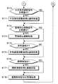
図12は本発明の連携システムに使用する図8の住警器10−1の処理の概略を例示したフローチャートである。図13において、住警器10−1の電池電源46による電源供給が開始されると、ステップS1で初期化、自己診断各種設定の読み込み等を実行し、異常がなければステップS2に進み、火災の有無を検知している。ステップS1で初期化異常があった場合には報知部40でその旨を報知して、動作を途中停止するか或いは再度ステップS1の処理を行うようにしているが、図示を省略している。 FIG. 12 is a flowchart illustrating an outline of the processing of the home guard 10-1 of FIG. 8 used in the linkage system of the present invention. In FIG. 13, when the power supply by the battery power source 46 of the mortgage alarm device 10-1 is started, initialization, reading of various self-diagnosis settings, etc. are executed in step S1, and if there is no abnormality, the process proceeds to step S2 and fire The presence or absence of is detected. If there is an initialization abnormality in step S1, the notification unit 40 notifies that fact and stops the operation halfway or performs the process of step S1 again, but the illustration is omitted.
図12及び図13は本発明の連携システムに使用する図8の住警器10−1の処理の概略を例示したフローチャートである。なお、このフローチャートでは先に説明したACK信号の送受信とそれに伴う処理は省略している。 FIG.12 and FIG.13 is the flowchart which illustrated the outline of the process of the residence guard 10-1 of FIG. 8 used for the cooperation system of this invention. In this flowchart, the transmission / reception of the ACK signal and the processing accompanying it are omitted.
図12において、住警器10−1の電池電源40による電源供給が開始されると、ステップS1で初期化、自己診断、各種設定の読み込み等を実行し、異常がなければステップS2に進み、火災の有無を検知している。ステップS1で初期化異常があった場合には報知部40でその旨を報知して動作を途中停止するか、或いは再度ステップS1の処理を行うようにしているが、図示を省略している。 In FIG. 12, when the power supply by the battery power source 40 of the residence guard 10-1 is started, initialization, self-diagnosis, reading of various settings, etc. are executed in step S1, and if there is no abnormality, the process proceeds to step S2. The presence or absence of a fire is detected. If there is an initialization abnormality in step S1, the notification unit 40 notifies that fact and stops the operation halfway, or the process of step S1 is performed again, but the illustration is omitted.
ステップS2において、センサ部38に設けた検煙部16から出力された煙検出信号が所定の火災レベルを超えると火災有りが検知されてステップS3に進み、火災連動処理と連携処理を行う。ステップS3の火災連動処理は、第1無線通信プロトコルに従った火災連動信号を生成して他の住警器10−2〜10−4に無線送信させた後、自己の警報動作として報知部40のスピーカ66から音声メッセージ等による警報音とLED22の例えば点灯による警報表示とにより連動元を示す火災警報を出力させる。
In step S2, when the smoke detection signal output from the
またステップS3の連携処理は、第2無線通信プロトコルに従った火災連携連動信号を生成させてゲートウェイ装置300を経由してサーバ500に送信させ、更にサーバ500から携帯電話ネットワーク600及び携帯電話基地局700を経由して携帯電話800に送信させて図6に示した火災警報画面を表示させると共に警報音を出力させる連携連動による火災警報を行わせる(火災の連携連動)。
In addition, the cooperation processing in step S3 generates a fire cooperation interlocking signal in accordance with the second wireless communication protocol, transmits the fire cooperation interlocking signal to the
続いて、ステップS4で検煙部16からの煙検出信号が低下して火災検知状態が解消する火災復旧の有無を検知しており、火災復旧有りを検知するとステップS5に進み、火災復旧連動処理と連携処理を行う。ステップS5の火災復旧連動処理は、第1無線通信プロトコルに従った火災復旧連動信号を他の住警器10−2〜10−4に送信させた後、スピーカ66からの警報音とLED22の点灯による連動元を示す火災警報を停止させる。ここで、LED22による警報表示は警報音の停止から所定時間経過後に消灯させても良い。
Subsequently, in step S4, the presence or absence of a fire restoration in which the smoke detection signal from the
またステップS5の連携処理は、第2無線通信プロトコルに従った火災復旧連携連動信号を生成させてゲートウェイ装置300を経由してサーバ500に送信させ、サーバ500から携帯電話ネットワーク600及び携帯電話基地局700を経由して携帯電話800に送信させて連携連動による火災警報を停止させる(火災復旧の連携連動)。
In addition, the cooperation processing in step S5 generates a fire recovery cooperation interlocking signal according to the second wireless communication protocol and transmits the fire recovery cooperation interlocking signal to the
続いてステップS6で警報停止スイッチ20の警報停止指示操作の有無を検知しており、スイッチ操作が検知されるとステップS7に進み、警報停止連動処理と連携処理を行う。ステップS7の警報停止連動処理は、第1無線通信プロトコルに従った警報停止連動信号を他の住警器10−2〜10−4に送信させ、自己のスピーカ66からの連動元を示す警報音出力を停止させ、LED22の点灯による警報表示を消灯させる。この場合、LED22による警報表示は警報音の停止からは所定時間経過後に消灯させても良い。
Subsequently, in step S6, the presence or absence of an alarm stop instruction operation of the
またステップS7の連携処理は、第2無線通信プロトコルに従った警報停止連携連動信号を生成させてゲートウェイ装置300を経由してサーバ500に送信させ、サーバ500から携帯電話ネットワーク600及び携帯電話基地局700を経由して携帯電話800に送信させて連携連動による火災警報を停止させる(警報停止の連携連動)。
In addition, the cooperation process in step S7 generates an alarm stop cooperation interlocking signal according to the second wireless communication protocol and transmits it to the
続いてステップS8に進み、他の住警器10−2〜10−4のいずれかから送信または中継送信された第1無線通信プロトコルに従った火災連動信号の有効受信の有無を検知している。他の住警器10−2〜10−4のいずれかからの火災連動信号の有効受信を検知すると、ステップS9に進み、火災連動処理と連携処理を行う。ステップS9の火災連動処理は、連動先を示す火災警報として自己の報知部40のスピーカ66から音声メッセージ等による警報音を出力させ、例えばLED22の点滅による警報表示を行わせる。このとき、必要に応じて他の住警器への中継送信或いは再中継送信を行わせるが、説明を省略する。ステップS11、S13についても同様である。
Then, it progresses to step S8 and the presence or absence of the effective reception of the fire interlocking signal according to the 1st radio | wireless communication protocol transmitted from any of other residence police devices 10-2 to 10-4 according to the 1st wireless communication protocol is detected. . When the effective reception of the fire interlocking signal from any of the other home alarm devices 10-2 to 10-4 is detected, the process proceeds to step S9, and the fire interlocking process and the cooperation process are performed. In the fire interlocking process in step S9, an alarm sound such as a voice message is output from the speaker 66 of the own notification unit 40 as a fire alarm indicating the interlock destination, and an alarm display by blinking of the
またステップS9の連携処理は、第2無線通信プロトコルに従った火災連携連動信号を生成させてゲートウェイ装置300を経由してサーバ500に送信させ、サーバ500から携帯電話ネットワーク600及び携帯電話基地局700を経由して携帯電話800に送信させて連携連動により火災警報を出力させる(火災警報の連携連動)。
In addition, in the cooperation process in step S9, a fire cooperation interlocking signal according to the second wireless communication protocol is generated and transmitted to the
次に図13のステップS10に進み、他の住警器10−2〜10−4から送信または中継送信された第1無線通信プロトコルに従った火災復旧連動信号の有効受信の有無を検知しており、火災復旧連動信号の有効受信を検知すると、ステップS11に進み、火災復旧連動処理と連携処理を行う。ステップS11の火災復旧連動処理は、連動先の警報として行っているスピーカ66からの警報音出力とLED22の点滅による警報表示を停止させる。
Next, the process proceeds to step S10 in FIG. 13 to detect the presence / absence of effective reception of the fire recovery interlocking signal according to the first wireless communication protocol transmitted or relayed from the other mortgages 10-2 to 10-4. If the effective reception of the fire recovery interlock signal is detected, the process proceeds to step S11 to perform the fire recovery interlock process and the cooperation process. In the fire recovery interlocking process of step S11, the alarm sound output from the speaker 66 and the alarm display by the blinking of the
またステップS11の連携処理は、第2無線通信プロトコルに従った火災復旧連携連動信号を生成させてゲートウェイ装置300を経由してサーバ500に送信させ、サーバ500から携帯電話ネットワーク600及び携帯電話基地局700を経由して携帯電話800に送信させて連携連動により火災警報を停止させる(火災復旧の連携連動)。
In addition, the cooperation processing in step S11 generates a fire recovery cooperation interlocking signal in accordance with the second wireless communication protocol and transmits the fire recovery cooperation interlocking signal to the
次にステップS12で他の住警器10−2〜10−4から送信または中継送信された第1無線通信プロトコルに従った警報停止連動信号の有効受信の有無を検知しており、警報停止連動信号の有効受信を検知すると、ステップS13に進み、連動警報停止連動処理と連携処理を行う。ステップS13の連動警報停止連動処理は、連動先の警報として行っているスピーカ66からの警報音出力とLED22の点滅による警報表示を停止させる。
Next, in step S12, the presence or absence of effective reception of the alarm stop interlocking signal according to the first wireless communication protocol transmitted or relayed from the other residential alarm devices 10-2 to 10-4 is detected, and the alarm stop interlocking is performed. When the effective reception of the signal is detected, the process proceeds to step S13, and the interlocking alarm stop interlocking process and the interlocking process are performed. The interlocking alarm stop interlocking process of step S13 stops the alarm display by the alarm sound output from the speaker 66 and the blinking of the
またステップS13の連携処理は、第2無線通信プロトコルに従った警報停止連携連動信号を生成させてゲートウェイ装置300を経由してサーバ500に送信させ、サーバ500から携帯電話ネットワーク600及び携帯電話基地局700を経由して携帯電話800に送信させて連携連動により火災警報を停止させる(警報停止の連携連動)。
In addition, the cooperation processing in step S13 generates an alarm stop cooperation interlocking signal according to the second wireless communication protocol and transmits the alarm stop cooperation interlocking signal to the
次にステップS14で発信機100から送信または中継送信された第1無線通信プロトコルに従った非常通報連動信号の有効受信の有無を検知しており、非常通報連動信号の有効受信を検知すると、ステップS15に進み、非常通報連動処理と連携処理を行う。ステップS15の非常通報連動処理は、スピーカ66から音声メッセージ等による非常通報警報音とLED22の例えば点灯による警報表示とにより非常通報を示す警報を出力する。
Next, in step S14, the presence or absence of effective reception of the emergency call interlocking signal according to the first wireless communication protocol transmitted or relayed from the
またステップS15の連携処理は、第2無線通信プロトコルに従った非常通報連携連動信号を生成させてゲートウェイ装置300を経由してサーバ500に送信させ、サーバ500から携帯電話ネットワーク600及び携帯電話基地局700を経由して携帯電話800に送信させて図7に示した非常通報警報画面を表示すると共に警報音を出力させて連携連動による非常通報警報動作を行わせる(非常通報の連携連動)。
In addition, the cooperation processing in step S15 generates an emergency call cooperation interlocking signal according to the second wireless communication protocol and transmits it to the
続いてステップS16に進み、住警器10−1自身でローバッテリー障害またはセンサ障害を検知した場合、又は、他の住警器10−2〜10−4から第1無線通信プロトコルに従いローバッテリー障害またはセンサ障害を示す障害連動信号の有効受信を検知した場合、ステップS17に進み、障害連動処理と連携処理を行う。ステップS17の障害連動処理は、連動元又は連動先を示すローバッテリー障害警報またはセンサ障害警報を警報音と警報表示で行わせる。またステップS17の連携処理は、第2無線通信プロトコルに従って対応する障害連携連動信号を生成させ、ゲートウェイ装置300を経由してサーバ500に送信させ、サーバ500から携帯電話ネットワーク600及び携帯電話基地局700を経由して携帯電話800に送信させて障害警報画面を表示すると共に警報音を出力させる連携連動による障害警報動作を行わせる。
Then, it progresses to step S16, and when a low battery failure or a sensor failure is detected by the home police device 10-1 itself, or a low battery failure is detected from the other home watch devices 10-2 to 10-4 according to the first wireless communication protocol. Or when the effective reception of the fault interlocking signal which shows a sensor fault is detected, it progresses to step S17 and performs a fault interlocking process and a cooperation process. In the fault interlocking process in step S17, a low battery fault alarm or a sensor fault alarm indicating the interlock source or the interlock destination is performed with an alarm sound and an alarm display. Also, in the cooperation processing in step S17, a corresponding failure cooperation interlocking signal is generated according to the second wireless communication protocol, transmitted to the
続いてステップS18で利用者の携帯電話800からサーバ500及びゲートウェイ装置300を経由して送られてくる連携連動信号の受信処理、例えば第2無線通信プロトコルに従った警報停止連携連動信号の有効受信を検知した場合に火災警報を停止し、更に、更に警報システムとの連携処理として第1無線通信プロトコルに従った警報停止連携連動信号を他の住警器10−2〜10−4に送信して警報停止させる。
Subsequently, in step S18, a reception process of the cooperation interlocking signal transmitted from the user's
図14は図9の発信機100の処理の概略を例示したフローチャートである。図14おいて、発信機100の電池電源146による電源供給が開始されると、ステップS21で初期化、自己診断、各種設定の読み込み等を実行し、異常がなければステップS22に進み、非常通報操作の有無を検知している。
FIG. 14 is a flowchart illustrating an outline of processing of the
ステップS22において、非常押釦スイッチ116による非常通報操作有りが検知されるとステップS23に進み、非常通報連動処理と連携処理を行う。ステップS23の非常通報連動処理は、第1無線通信プロトコルに従った非常通報信号を他の住警器に無線送信させると共に、報知部140のスピーカ164から音声メッセージ等による警報音とLED118の例えば点灯による警報表示とにより非常通報警報を出力させる。またステップS23の連携処理は、第2無線通信プロトコルに従った非常通報信号を生成させてゲートウェイ装置300に送信させる。
In step S22, when it is detected that there is an emergency call operation by the emergency
続いてステップS24に進み、住警器10−1〜10−4のいずれかから送信または中継送信された第1無線通信プロトコルに従った火災連動信号の有効受信の有無を検知している。他の住警器10−1〜10−4のいずれかからの火災連動信号の有効受信を検知すると、ステップS25に進み、火災連動処理と連携処理を行う。ステップS25の火災連動処理は、連動先を示す火災警報として自己の報知部140のスピーカ164から音声メッセージ等による警報音を出力させ、例えばLED118の点滅による警報表示を行わせる。このとき、必要に応じて住警器への中継送信或いは再中継送信を行わせるが、説明を省略する。ステップS11、S13についても同様である。
Then, it progresses to step S24, and the presence or absence of the effective reception of the fire interlocking signal according to the 1st radio | wireless communication protocol transmitted or relay-transmitted from either of the resident guards 10-1 to 10-4 is detected. When the effective reception of the fire interlocking signal from any of the other home alarm devices 10-1 to 10-4 is detected, the process proceeds to step S25, and the fire interlocking process and the cooperation process are performed. In the fire interlocking process in step S25, an alarm sound such as a voice message is output from the speaker 164 of the self-notification unit 140 as a fire alarm indicating the interlocking destination, and an alarm display by blinking of the
またステップS25の連携処理は、第2無線通信プロトコルに従った火災連携連動信号を生成させてゲートウェイ装置300を経由してサーバ500に送信させ、サーバ500から携帯電話ネットワーク600及び携帯電話基地局700を経由して携帯電話800に送信させて連携連動により火災警報を出力させる。
In addition, the cooperation processing in step S25 generates a fire cooperation interlocking signal in accordance with the second wireless communication protocol and transmits the fire cooperation interlocking signal to the
次にステップS26で住警器10−1〜10−4から送信または中継送信された第1無線通信プロトコルに従った火災復旧連動信号の有効受信の有無を検知しており、火災復旧連動信号の有効受信を検知すると、ステップS27に進み、火災復旧連動処理と連携処理を行う。ステップS27の火災復旧連動処理は、連動先の警報として行っているスピーカ164からの警報音出力とLED118の点滅による警報表示を停止させる。
Next, in step S26, the presence or absence of effective reception of the fire recovery interlock signal in accordance with the first wireless communication protocol transmitted or relayed from the home alarm devices 10-1 to 10-4 is detected. When valid reception is detected, the process proceeds to step S27, and fire recovery interlocking processing and cooperation processing are performed. In the fire recovery interlocking process in step S27, the alarm display by the alarm sound output from the speaker 164 and the blinking of the
またステップS27の連携処理は、第2無線通信プロトコルに従った火災復旧連携連動信号を生成させてゲートウェイ装置300を経由してサーバ500に送信させ、サーバ500から携帯電話ネットワーク600及び携帯電話基地局700を経由して携帯電話800に送信させて連携連動により火災警報を停止させる。
In addition, the cooperation processing in step S27 generates a fire recovery cooperation interlocking signal according to the second wireless communication protocol and transmits the fire recovery cooperation interlocking signal to the
次にステップS28で住警器10−1〜10−4から送信または中継送信された第1無線通信プロトコルに従った警報停止連動信号の有効受信の有無を検知しており、警報停止連動信号の有効受信を検知すると、ステップS29に進み、連動警報停止連動処理と連携処理を行う。ステップS13の連動警報停止連動処理は、連動先の警報として行っているスピーカ164からの警報音出力とLED118の点滅による警報表示を停止させる。
Next, in step S28, the presence or absence of an effective reception of the alarm stop interlocking signal according to the first wireless communication protocol transmitted or relay-transmitted from the residential alarm devices 10-1 to 10-4 is detected. When valid reception is detected, the process proceeds to step S29, and the interlocking alarm stop interlocking process and the cooperation process are performed. The interlocking alarm stop interlocking process of step S13 stops the alarm display by the alarm sound output from the speaker 164 and the blinking of the
またステップS29の連携処理は、第2無線通信プロトコルに従った警報停止連携連動信号を生成させてゲートウェイ装置300を経由してサーバ500に送信させ、サーバ500から携帯電話ネットワーク600及び携帯電話基地局700を経由して携帯電話800に送信させて連携連動により火災警報を停止させる。
In addition, the cooperation processing in step S29 generates an alarm stop cooperation interlocking signal according to the second wireless communication protocol and transmits it to the
続いてステップS30に進み、発信機100自身でローバッテリー障害またはセンサ障害を検知した場合、又は、他の発信機や住警器10−1〜10−4から第1無線通信プロトコルに従いローバッテリー障害またはセンサ障害を示す障害連動信号の有効受信を検知した場合、ステップS31に進み、障害連動処理と連携処理を行う。ステップS31の障害連動処理は、連動元又は連動先を示すローバッテリー障害警報またはセンサ障害警報を警報音と警報表示で行わせる。またステップS31の連携処理は、第2無線通信プロトコルに従って対応する障害連携連動信号を生成させ、ゲートウェイ装置300を経由してサーバ500に送信させ、サーバ500から携帯電話ネットワーク600及び携帯電話基地局700を経由して携帯電話800に送信させて障害警報画面を表示すると共に警報音を出力させる連携連動による障害警報動作を行わせる。
Then, it progresses to step S30, and when the low battery failure or the sensor failure is detected by the
図15は図1に示すサーバ500の処理の概略を例示したフローチャートである。図15において、サーバ500が電源投入により起動すると、ステップS41で初期化、自己診断、各種設定の読み込み等を実行し、異常がなければステップS42に進み、電力管理処理を実行する。
FIG. 15 is a flowchart illustrating an outline of processing of the
ステップS42の電力管理処理は、電源コンセント装置200から送られてきた電力検知信号に基づき消費電力量や総消費電力量等を求め、携帯電話800からの閲覧要求信号を受信した場合、住宅24の家電機器の消費電力情報を送信して表示させる。
In the power management process in step S42, the power consumption amount, the total power consumption amount, etc. are obtained based on the power detection signal sent from the power outlet device 200, and when the browsing request signal from the
続いてステップS43で携帯電話800からの在宅確認要求信号による在宅確認要求の有無を検知しており、在宅確認要求有りを検知するとステップS44に進み、ゲートウェイ装置300を経由して住警器10に設けた人感センサ15から人検知信号を取得させ、携帯電話800に図5に示したような在宅情報画面810を表示させる。
Subsequently, in step S43, the presence / absence of a home confirmation request from the home confirmation request signal from the
続いてステップS45で住警器10からの火災連携連動信号の有効受信の有無を検知しており、火災連動信号の有効受信有りを検知するとステップS46に進み、火災連携処理として、携帯端末800に図6に示したような火災警報画面818を表示させると共に警報音を出力させる。
Subsequently, in step S45, the presence / absence of effective reception of the fire-linked signal from the home alarm device 10 is detected. If it is detected that the fire-linked signal is effectively received, the process proceeds to step S46, and the
またステップS46の火災連携処理にあっては、図6の火災警報画面818に設けた在宅確認釦818の操作による在宅確認要求信号を受信した場合には、ゲートウェイ装置300を介して住警器10に設けた人感センサ15から人検知信号を取得させ、図5に示したような在宅情報画面810を携帯電話800に表示させる。
Moreover, in the fire cooperation process of step S46, when the home confirmation request signal by operation of the
続いてステップS47で発信機100からの非常通報連携連動信号の有効受信の有無を検知しており、非常通報連携連動信号の有効受信有りを検知するとステップS48に進み、非常通報連携処理として、携帯端末800に図7に示したような非常通報警報画面828を表示させると共に警報音を出力させる。
Subsequently, in step S47, the presence / absence of effective reception of the emergency call cooperation interlocking signal from the
またステップS48の非常通報連携処理にあっては、図7の非常通報警報画面828に設けた在宅確認釦818の操作による在宅確認要求信号を受信有りを検知した場合には、ゲートウェイ装置300を介して住警器10に設けた人感センサ15から人検知信号を取得させ、図5に示したような在宅情報画面810を携帯電話800に表示させる。
Further, in the emergency call linkage processing in step S48, when it is detected that a home confirmation request signal by operating the
続いてステップS49で住警器10からの火災復旧連携連動信号の有効受信の有無を検知しており、火災復旧連携連動信号の有効受信有りを検知するとステップS50に進み、携帯端末800による火災警報を停止させる。
Subsequently, in step S49, the presence / absence of effective reception of the fire recovery cooperation interlocking signal from the home alarm device 10 is detected. If the presence of effective reception of the fire recovery cooperation interlocking signal is detected, the process proceeds to step S50, and the fire alarm by the
続いてステップS51で住警器10からの警報停止連携連動信号の有効受信の有無を検知しており、警報停止連携連動信号の有効受信有りを検知するとステップS52に進み、携帯端末800による火災警報又は非常通報警報を停止させる。
Subsequently, in step S51, the presence / absence of effective reception of the alarm stop cooperation interlocking signal from the resident alarm 10 is detected. When the presence of effective reception of the alarm stop cooperation interlocking signal is detected, the process proceeds to step S52, and the fire alarm by the
続いてステップS53で住警器10又は発信機100からローバッテリー障害などの障害連携連動信号の有効受信有りを検知した場合、ステップS54に進み、携帯電話800から住警器10又は発信機100の障害情報を報知させる。
Subsequently, when it is detected in step S53 that there is an effective reception of a fault cooperation interlocking signal such as a low battery fault from the home alarm device 10 or the
なお、上記の実施形態における警報システムは火災を検知して警報する住警器の連動システムを例にとるものであったが、住警器以外の火災警報器、ガス漏れ警報器、CO警報器、各種の防犯用警報器、地震警報器(緊急地震速報受信機等)、その他任意の警報器を配置した警報システムやそれら各種の警報器を混在させて配置した警報システムについても同様に適用できる。更に、これらの警報器に加え中継装置や受信装置を含むシステムにも適用できる。 The alarm system in the above embodiment is an example of an interlocking system of a residential alarm that detects and alerts a fire. However, a fire alarm other than a residential alarm, a gas leak alarm, a CO alarm It can be applied in the same way to various alarm devices, crime prevention alarms, earthquake alarms (emergency earthquake warning receivers, etc.), other alarm systems with any alarm devices, and mixed alarm devices. . Furthermore, the present invention can be applied to a system including a relay device and a receiving device in addition to these alarm devices.
また図8の住警器10−1にあっては、検煙部16を備え、火災に伴い発生する煙を観測して監視領域の火災を検知する煙式火災警報器を例に取っているが、これ以外に火災に伴う熱を検出するサーミスタ等の温度検知素子を備えた熱式住警器や火災に伴うその他の環境変化を検知する火災警報器、火災以外にガス漏れを検知する警報器、侵入者や地震その他の異状を検知する各種の警報器、これらを組み合わせて成る警報器についても、本発明の対象に含まれる。
In addition, the residential alarm device 10-1 of FIG. 8 is provided with a
また、警報器の連動や各部の連携にかかる通信は無線通信によるものでなくても良く、有線通信によっても、また有線と無線を適宜混在させるものであっても良い。この場合、各通信プロトコルはそれらに適合したものに代えれば良い。また、インターネット400についても、本発明の機能を実現できる他のネットワークに代えることができる。
Further, the communication related to the alarm device linkage and the cooperation of each unit does not have to be performed by wireless communication, and may be performed by wired communication or by appropriately mixing wired and wireless communication. In this case, each communication protocol may be replaced with a protocol adapted to them. Also, the
また、上記の実施形態では第1無線通信プロトコルと第2無線通信プロトコルの変換は住警器側で行っているが、これをゲートウェイ装置側で行うようにしても良い。この場合は上記実施形態のゲートウェイ装置300に、第1無線通信部と、第1無線通信プロトコルと第2無線通信プロトコルの変換処理部を設け、第2無線通信部と協働して処理するようにする。このようなシステムでは、警報器の第2無線通信部は省略できる。
Further, in the above embodiment, the conversion between the first wireless communication protocol and the second wireless communication protocol is performed on the side of the house alarm, but this may be performed on the gateway device side. In this case, the
また、本発明の機器連携システムは、警報システムを構成する警報器が1台であることを妨げない。 Moreover, the apparatus cooperation system of this invention does not prevent that the alarm device which comprises an alarm system is one.
また上記の実施形態における機器管理システムは、家電機器の消費電力を管理する場合を例にとるものであったが、センサネットワークにより各種の環境変化を検知してエアコン等の家電機器を最適制御するといった適宜の機器管理システムと連携することもできる。もちろん、電力管理制御とこのような環境管理制御とを複合的に行う機器連携システムとしても良い。 The device management system in the above embodiment is an example of managing the power consumption of home appliances. However, various environmental changes are detected by a sensor network to optimally control home appliances such as air conditioners. It is also possible to link with an appropriate device management system. Of course, it is good also as an apparatus cooperation system which performs power management control and such environmental management control in combination.
また上記の実施形態におけるフローチャートは処理の概略例を説明したもので、処理の順番等はこれに限定されない。また各処理や処理と処理の間に必要に応じて遅延時間を設けたり、他の判定処理やその他の処理を挿入する等ができる。 In addition, the flowcharts in the above-described embodiments have described a schematic example of processing, and the order of processing is not limited to this. In addition, a delay time can be provided between the processes or between the processes, and other determination processes or other processes can be inserted.
また上記の実施形態し利用者端末として携帯電話を例にとっているが、無線ネットワーク又は有線ネットワークでサーバに接続可能な携帯端末など適宜の利用者端末を含む。 In the above embodiment, a mobile phone is taken as an example of the user terminal, but includes an appropriate user terminal such as a mobile terminal that can be connected to a server via a wireless network or a wired network.
また、上記実施の形態で示したプロセッサは、その機能の一部又は全部を、例えばワイヤードロジック等による他の手段に代えることができる。プロセッサを含め他の電気的、機能的構成は適宜に統廃合することもできる。 In addition, the processor shown in the above embodiment can replace some or all of its functions with other means such as wired logic. Other electrical and functional configurations including the processor can be appropriately integrated and abolished.
また、上記の実施形態は住宅(住戸)用に限らずビルやオフィス用など各種用途の警報システムと機器管理システムの連携にも適用できる。 In addition, the above embodiment can be applied not only to a house (dwelling unit) but also to a cooperation between an alarm system for various uses such as a building or an office and a device management system.
また各装置の設置場所や管理者は任意で、例えばサーバ500は電力会社に設置されて電力会社によって管理され、警報器は家庭内に設置することができる。
The installation location and manager of each device are arbitrary. For example, the
また本発明は上記の実施形態に限定されず、その目的と利点を損なうことのない適宜の変形を含み、更に上記の実施形態に示した数値による限定は受けない。
The present invention is not limited to the above-described embodiments, includes appropriate modifications that do not impair the objects and advantages thereof, and is not limited by the numerical values shown in the above-described embodiments.
10−1〜10−4:住警器
24:住宅
28,56,128,156,208,228,302,328:プロセッサ
30,130:第1無線通信部
34,134,210,310:第2無線通信部
32,36,132,136,212,312:アンテナ
38:センサ部
40:報知部
42:操作部
44:メモリ
46:電池電源
48:第1送信回路
50:第1受信回路
52,152,222,322:第2送信回路
54,154,224,324:第2受信回路
60:警報制御部
62:連携処理部
100:発信機
200−1〜200−5:電源コンセント装置
202:インレット
204:アウトレット
206:センサ
226:電力測定部
300:ゲートウェイ装置
304:有線通信部
400:インターネット
500:サーバ
502:機器管理部
504:警報器管理部
600:携帯電話ネットワーク
700:携帯電話基地局
800:携帯電話
802:警報画面
10-1 to 10-4: House alarm device 24:
202 : Inlet
204 : Outlet
206 : Sensor 226: Power measurement unit 300: Gateway device 304: Wired communication unit 400: Internet 500: Server 502: Device management unit 504: Alarm management unit 600: Mobile phone network 700: Mobile phone base station 800: Mobile phone 802 : Alarm screen
Claims (2)
所定の機器の状態を検知して第2通信プロトコルに従った状態検知信号を送信する機器状態検知装置、前記状態検知信号を含む第2通信プロトコルに従った各種信号を受信した場合に、当該受信した信号をインターネット通信プロトコルに従った信号に変換して送信し、サーバから在宅確認要求信号を受信した場合に、当該在宅確認要求信号を第2通信プロトコルに従った信号に変換して送信し、第2通信プロトコルに従った人検知信号を受信した場合に、当該人検知信号をインターネット通信プロトコルに従った信号に変換して送信するネットワークアダプタ、及び、前記ネットワークアダプタから受信した信号に対応した処理を行い、当該処理結果を利用者端末に送信して出力させる前記サーバを設けた機器管理システムと、
を備え、
前記複数の警報器の何れかに、前記異状を検知した場合又は第1通信プロトコルに従った異状連動信号を受信した場合に、第2通信プロトコルに従った異状連携連動信号を送信し、第2通信プロトコルに従った在宅確認要求信号を受信した場合に、第1通信プロトコルに従った在宅確認要求信号を送信し、第1通信プロトコルに従った人検知信号を受信した場合に、第2通信プロトコルに従った人検知信号を送信する連携処理部を設け、
前記サーバに、
前記ネットワークアダプタから異状連携連動信号を受信した場合に、当該異状連携連動信号の処理結果を前記利用者端末に送信して異状警報を出力させる警報器管理部と、
前記利用者端末から在宅確認要求信号を受信した場合に、前記ネットワークアダプタに在宅確認要求信号を送信して前記複数の警報器から人検知信号を取得し、当該人検知信号に基づき前記複数の警報器の設置場所に対応した在宅情報を生成して、当該在宅情報を前記利用者端末に表示させる在宅管理部と、
を設けたことを特徴とする警報連携システム。
When an abnormality is detected, an abnormality alarm is output, an abnormality interlocking signal according to the first communication protocol is transmitted, and when an abnormality interlocking signal according to the first communication protocol is received, an abnormality alarm is output, An alarm system provided with a plurality of alarm devices for detecting presence / absence of a person by a human sensor and transmitting a person detection signal according to the first communication protocol when a home confirmation request signal according to one communication protocol is received; ,
A device state detection device that detects a state of a predetermined device and transmits a state detection signal in accordance with the second communication protocol, and receives various signals in accordance with the second communication protocol including the state detection signal. When the home confirmation request signal is received from the server , the home confirmation request signal is converted into a signal according to the second communication protocol and transmitted. When a human detection signal according to the second communication protocol is received, a network adapter that converts the human detection signal into a signal according to the Internet communication protocol and transmits the signal, and processing corresponding to the signal received from the network adapter And a device management system provided with the server for sending the processing result to the user terminal and outputting it,
With
When detecting the abnormality or receiving an abnormality interlocking signal in accordance with the first communication protocol, any of the plurality of alarm devices transmits an abnormality cooperation interlocking signal in accordance with the second communication protocol; When the home confirmation request signal according to the communication protocol is received, the second communication protocol is transmitted when the home confirmation request signal according to the first communication protocol is transmitted and the person detection signal according to the first communication protocol is received. Provided a cooperation processing unit to send a human detection signal according to
To the server,
When receiving an abnormal cooperation interlocking signal from the network adapter, an alarm management unit that transmits the processing result of the abnormal cooperation interlocking signal to the user terminal and outputs an abnormal alarm;
When a home confirmation request signal is received from the user terminal, a home detection request signal is transmitted to the network adapter to obtain a person detection signal from the plurality of alarm devices, and the plurality of alarms are based on the person detection signal. A home management unit for generating home information corresponding to the installation location of the device and displaying the home information on the user terminal;
An alarm linkage system characterized by providing
前記複数の警報器は、異状復旧、警報停止又は障害を検知した場合に、第1通信プロトコルに従った異状復旧、警報停止又は障害の連動信号を送信し、
前記連携処理部は、第1通信プロトコルに従った異状復旧、警報停止又は障害の連動信号を受信した場合に、第2通信プロトコルに従った異状復旧、警報停止又は障害の連携連動信号を送信し、
前記ネットワークアダプタは、第2通信プロトコルに従った異状復旧、警報停止又は障害の連携連動信号を受信した場合に、当該連携連動信号をインターネット通信プロトコルに従った信号に変換して送信し、
前記サーバの警報器管理部は、前記ネットワークアダプタから異状復旧、警報停止又は障害の連携連動信号を受信した場合に、当該連携連動信号の処理結果を前記利用者端末に送信して出力させることを特徴とする警報連携システム。
In the alarm linkage system according to claim 1 ,
The plurality of alarm devices, when abnormality recovery, alarm stop or failure is detected, transmit an abnormality recovery, alarm stop or failure interlocking signal according to the first communication protocol,
When the cooperation processing unit receives an abnormality recovery, alarm stop or failure interlocking signal according to the first communication protocol, it transmits an abnormality recovery, alarm stop or failure cooperation interlocking signal according to the second communication protocol. ,
When the network adapter receives a cooperative link signal of abnormality recovery, alarm stop or failure according to the second communication protocol, it converts the cooperative link signal into a signal according to the Internet communication protocol, and sends it.
The alarm management unit of the server, when receiving the cooperation recovery signal of abnormality recovery, alarm stop or failure from the network adapter, transmits the processing result of the cooperation interlocking signal to the user terminal for output. Characteristic alarm linkage system.
Priority Applications (1)
| Application Number | Priority Date | Filing Date | Title |
|---|---|---|---|
| JP2011107033A JP5893847B2 (en) | 2011-05-12 | 2011-05-12 | Alarm linkage system |
Applications Claiming Priority (1)
| Application Number | Priority Date | Filing Date | Title |
|---|---|---|---|
| JP2011107033A JP5893847B2 (en) | 2011-05-12 | 2011-05-12 | Alarm linkage system |
Publications (3)
| Publication Number | Publication Date |
|---|---|
| JP2012238189A JP2012238189A (en) | 2012-12-06 |
| JP2012238189A5 JP2012238189A5 (en) | 2014-05-22 |
| JP5893847B2 true JP5893847B2 (en) | 2016-03-23 |
Family
ID=47461031
Family Applications (1)
| Application Number | Title | Priority Date | Filing Date |
|---|---|---|---|
| JP2011107033A Active JP5893847B2 (en) | 2011-05-12 | 2011-05-12 | Alarm linkage system |
Country Status (1)
| Country | Link |
|---|---|
| JP (1) | JP5893847B2 (en) |
Families Citing this family (8)
| Publication number | Priority date | Publication date | Assignee | Title |
|---|---|---|---|---|
| JP2014182664A (en) * | 2013-03-20 | 2014-09-29 | Hochiki Corp | Alarm system |
| TWI608436B (en) * | 2014-01-09 | 2017-12-11 | 紅米國際旅館有限公司 | Service management method and computer system thereof |
| CN105761460B (en) * | 2016-04-21 | 2018-07-10 | 珠海市埃帝尔软件技术有限公司 | A kind of comprehensive integrated safety precaution analysis alarm system and method |
| CN106054731A (en) * | 2016-07-12 | 2016-10-26 | 山东智慧生活数据系统有限公司 | Intelligent kitchen safety system |
| CN107590972A (en) * | 2017-08-10 | 2018-01-16 | 深圳市亚晔实业有限公司 | A kind of slave computer alarm and remote alarming system |
| CN109993948A (en) * | 2017-12-29 | 2019-07-09 | 深圳市云海物联科技有限公司 | A kind of safety protecting method, central controller and security protection system |
| JP7144486B2 (en) * | 2020-07-20 | 2022-09-29 | ホーチキ株式会社 | Management equipment and communication system |
| CN114115069B (en) * | 2021-12-06 | 2023-06-09 | 深圳市海曼科技股份有限公司 | Cloud local combination linkage method and system |
Family Cites Families (5)
| Publication number | Priority date | Publication date | Assignee | Title |
|---|---|---|---|---|
| JP3794343B2 (en) * | 2002-04-15 | 2006-07-05 | 松下電工株式会社 | Center server for monitoring and control system for housing complex |
| JP4709607B2 (en) * | 2005-08-02 | 2011-06-22 | 株式会社東芝 | Network home appliance control system |
| JP4987567B2 (en) * | 2007-05-23 | 2012-07-25 | 日本電信電話株式会社 | Disaster prevention support system and disaster prevention support method |
| JP2010049455A (en) * | 2008-08-21 | 2010-03-04 | Hochiki Corp | Residential control apparatus and residential alarm unit |
| JP2011081595A (en) * | 2009-10-07 | 2011-04-21 | Hochiki Corp | Alarm system, alarm, and emergency call device |
-
2011
- 2011-05-12 JP JP2011107033A patent/JP5893847B2/en active Active
Also Published As
| Publication number | Publication date |
|---|---|
| JP2012238189A (en) | 2012-12-06 |
Similar Documents
| Publication | Publication Date | Title |
|---|---|---|
| JP6125759B2 (en) | Alarm linkage system | |
| JP5893847B2 (en) | Alarm linkage system | |
| JP5815278B2 (en) | Alarm linkage system | |
| JP6022797B2 (en) | Alarm linkage system | |
| TWI428862B (en) | Fire alarm | |
| JP5116841B2 (en) | Alarm and alarm system | |
| JP6009813B2 (en) | Alarm linkage system | |
| JP2012238190A (en) | Alarm cooperation system, alarm cooperation method and repeater | |
| JP2010033518A (en) | Alarm | |
| JP6027310B2 (en) | Alarm linkage system | |
| JP5461858B2 (en) | Alarm system | |
| JP5350705B2 (en) | Controller device | |
| WO2013062101A1 (en) | Alert linking system and network adapter | |
| JP5893925B2 (en) | Cooperation system | |
| JP2014041519A (en) | Cooperative notification system | |
| JP5964559B2 (en) | Alarm linkage system | |
| JP2013092968A (en) | Alarm cooperation system, alarm cooperation method, alarm and catv adaptor | |
| JP2009237873A (en) | Alarm system | |
| JP6110125B2 (en) | Alarm system | |
| JP5744438B2 (en) | Alarm system and transmitter | |
| JP5848136B2 (en) | Cooperation system | |
| JP2010020663A (en) | Alarm | |
| JP6022786B2 (en) | Alarm linkage system | |
| JP2016076238A (en) | Cooperation system | |
| JP2012168914A (en) | Alarm unit and monitoring system |
Legal Events
| Date | Code | Title | Description |
|---|---|---|---|
| A521 | Written amendment |
Free format text: JAPANESE INTERMEDIATE CODE: A523 Effective date: 20140407 |
|
| A621 | Written request for application examination |
Free format text: JAPANESE INTERMEDIATE CODE: A621 Effective date: 20140508 |
|
| A977 | Report on retrieval |
Free format text: JAPANESE INTERMEDIATE CODE: A971007 Effective date: 20150130 |
|
| A131 | Notification of reasons for refusal |
Free format text: JAPANESE INTERMEDIATE CODE: A131 Effective date: 20150210 |
|
| A521 | Written amendment |
Free format text: JAPANESE INTERMEDIATE CODE: A523 Effective date: 20150413 |
|
| A131 | Notification of reasons for refusal |
Free format text: JAPANESE INTERMEDIATE CODE: A131 Effective date: 20150909 |
|
| A521 | Written amendment |
Free format text: JAPANESE INTERMEDIATE CODE: A523 Effective date: 20151105 |
|
| A131 | Notification of reasons for refusal |
Free format text: JAPANESE INTERMEDIATE CODE: A131 Effective date: 20151202 |
|
| A521 | Written amendment |
Free format text: JAPANESE INTERMEDIATE CODE: A523 Effective date: 20160106 |
|
| TRDD | Decision of grant or rejection written | ||
| A01 | Written decision to grant a patent or to grant a registration (utility model) |
Free format text: JAPANESE INTERMEDIATE CODE: A01 Effective date: 20160127 |
|
| A61 | First payment of annual fees (during grant procedure) |
Free format text: JAPANESE INTERMEDIATE CODE: A61 Effective date: 20160225 |
|
| R150 | Certificate of patent or registration of utility model |
Ref document number: 5893847 Country of ref document: JP Free format text: JAPANESE INTERMEDIATE CODE: R150 |