JP5888726B2 - Solid fuel boiler system and solid fuel burner - Google Patents
Solid fuel boiler system and solid fuel burner Download PDFInfo
- Publication number
- JP5888726B2 JP5888726B2 JP2011251744A JP2011251744A JP5888726B2 JP 5888726 B2 JP5888726 B2 JP 5888726B2 JP 2011251744 A JP2011251744 A JP 2011251744A JP 2011251744 A JP2011251744 A JP 2011251744A JP 5888726 B2 JP5888726 B2 JP 5888726B2
- Authority
- JP
- Japan
- Prior art keywords
- carrier gas
- coarse powder
- gas pipe
- temperature
- air
- Prior art date
- Legal status (The legal status is an assumption and is not a legal conclusion. Google has not performed a legal analysis and makes no representation as to the accuracy of the status listed.)
- Expired - Fee Related
Links
Images


Description
本発明は、固体燃料を燃焼させるボイラに係り、特に泥炭、褐炭、亜瀝青炭など燃料比が低い低品位炭で、水分量が多く燃焼前に乾燥処理を要する固体燃料を効率良く燃焼させることができ、主に火力発電プラントに用いられる固体燃料ボイラシステムと固体燃料用バーナに関する。 The present invention relates to a boiler that burns solid fuel, particularly low-grade coal with a low fuel ratio such as peat, lignite, subbituminous coal, and the like, which can efficiently burn solid fuel that has a high water content and needs to be dried before combustion. The present invention relates to a solid fuel boiler system and a solid fuel burner mainly used in a thermal power plant.
褐炭は資源量が豊富で安価な燃料であるが、水分が重量比で40〜60%程度と非常に多く、そのままでは輸送に適さない。そこで褐炭を脱水・乾燥して利用するための技術が種々開発されているが、経済性等の面で広く普及するには至っていない。このようなことから、火力発電プラント用ボイラの燃料としての褐炭は、産炭地付近のプラントで特に脱水・乾燥処理を行うことなく、直接燃料としてボイラに供給されることも多い。しかし、この場合、発生した熱の多くが水分の蒸発に消費されるため、最終的な発電効率が低くなることが避けられない。 Brown coal is an inexpensive fuel with abundant resources, but its moisture content is very high at about 40 to 60% by weight, and it is not suitable for transportation as it is. Accordingly, various techniques for dehydrating and drying lignite have been developed, but they have not been widely used in terms of economy and the like. For this reason, lignite as a fuel for a boiler for a thermal power plant is often supplied directly to the boiler as a fuel without performing a dehydration / drying process in a plant near the coal-producing area. However, in this case, since much of the generated heat is consumed for the evaporation of moisture, it is inevitable that the final power generation efficiency is lowered.
特許文献1(特開昭59−97408号公報)には、理論燃焼空気量以下の空気量で搬送される微粉炭と理論燃焼空気量以上の空気量で搬送される粗粉炭を混合しないように同一の燃焼バーナから火炉内に噴射して微粉燃焼ガスと粗粉燃焼ガスからそれぞれ微粉火炎と粗粉火炎を炉内で形成させ、炉内で微粉燃焼ガスと粗粉燃焼ガスを十分に混合させることで微粉燃焼ガス中のNH3及びHCNを粗粉燃焼ガス中のNOxと反応させてNOxをN2に還元させ、また微粉燃焼ガス中の未燃分を粗粉燃焼ガス中の余剰酸素と反応させることで、石炭中の未燃分の発生が減り、排ガス中のNOx濃度も減少することができると記載されている。 In Patent Document 1 (Japanese Patent Application Laid-Open No. 59-97408), pulverized coal conveyed with an air amount less than the theoretical combustion air amount and coarse pulverized coal conveyed with an air amount greater than the theoretical combustion air amount are not mixed. Inject into the furnace from the same combustion burner to form fine powder flame and coarse powder flame from the fine powder combustion gas and coarse powder combustion gas, respectively, and thoroughly mix the fine powder combustion gas and coarse powder combustion gas in the furnace By reacting NH 3 and HCN in the fine powder combustion gas with NOx in the coarse powder combustion gas, NOx is reduced to N 2, and unburned content in the fine powder combustion gas is reduced with excess oxygen in the coarse powder combustion gas. It is described that, by reacting, the generation of unburned coal in coal is reduced and the NOx concentration in exhaust gas can also be reduced.
特許文献2(特開平1−217110号公報)には、微粉炭と粗粉炭をバーナノズルに接続する石炭搬送管内を搬送中に、該石炭搬送管内に設けたルーバ型粗粉分離器で微粉炭をバーナノズルの出口部の内壁側に集めてバーナノズルの出口部に設けた保炎器により微粉炭を捕捉させて微粉炭の着火を促進する構成が開示されている。 In Patent Document 2 (JP-A-1-217110), pulverized coal and pulverized coal are transported through a coal transport pipe connected to a burner nozzle, and pulverized coal is removed by a louver type coarse powder separator provided in the coal transport pipe. A configuration is disclosed in which pulverized coal is captured by a flame holder provided on the inner wall side of the outlet portion of the burner nozzle and provided at the outlet portion of the burner nozzle to promote ignition of the pulverized coal.
特許文献3(特開平5−237413号公報)には、石炭粉砕用ミル内で粉砕した微粉炭を、該ミルの出口部からバーナノズルに供給する際に、ミルの出口部にある回転式分級器に設けた固定羽根の取り付け角度を調整することで20ミリミクロン以下の微粉炭を一定量以上バーナノズルに供給できるようにして、低負荷時にもバーナノズル出口での石炭の着火性、保炎性を保つことができるようにした構成が開示されている。 Patent Document 3 (Japanese Patent Application Laid-Open No. 5-237413) discloses a rotary classifier at the outlet of a mill when supplying pulverized coal pulverized in a coal pulverizing mill to a burner nozzle from the outlet of the mill. By adjusting the mounting angle of the fixed blades provided in the pulverized coal, it is possible to supply more than a certain amount of pulverized coal to the burner nozzle at a certain amount or more, so that the ignitability and flame holding performance of the coal at the burner nozzle outlet is maintained even at low load. A configuration that can be used is disclosed.
上記特許文献記載の発明には褐炭などの低品位炭の燃焼性については触れられていない。褐炭は炭化されていない木質分の割合が多く、繊維質の木質分は微粉砕されずに微粉砕機内部に滞留して粉砕動力を過剰に消費する。そのため、火力発電プラントとしての効率を低めるという問題点があった。 The invention described in the above patent document does not mention the combustibility of low-grade coal such as lignite. Brown coal has a large proportion of wood that is not carbonized, and fibrous wood remains in the pulverizer without being finely pulverized and consumes excessive pulverization power. For this reason, there is a problem that the efficiency as a thermal power plant is lowered.
本発明の課題は、泥炭や褐炭のように高水分の石炭を燃料とする固体燃料ボイラにおいて、低コストで効率良く燃料中の水分を低減し、設備費や粉砕動力の増大を抑制して、火力発電プラントの効率(発電端効率)向上に寄与する固体燃料ボイラシステムと該システムに使用し得る固体燃料バーナを提供することである。 The subject of the present invention is a solid fuel boiler that uses high-moisture coal as fuel, such as peat and lignite, to reduce moisture in the fuel efficiently at low cost, and to suppress an increase in equipment costs and grinding power, To provide a solid fuel boiler system that contributes to improving the efficiency (power generation end efficiency) of a thermal power plant and a solid fuel burner that can be used in the system.
本発明の上記課題は次の解決手段で解決される。
請求項1記載の発明は、2以上の固体燃料バーナ(15,15,・・・)からなるバーナグループを複数グループ備えた固体燃料ボイラ(124)と、該ボイラ(124)からの排ガスと燃焼用ガス及び搬送ガスとを熱交換するガス予熱器(18)とを有する固体燃料ボイラシステムであって、各固体燃料バーナ(15)には、固体燃料の粗粉と微粉とをそれぞれ別系統で導入して燃焼させるための、粗粉供給系統と微粉供給系統とが接続されており、前記粗粉供給系統は、前記ガス予熱器(18)を経由して固体燃料搬送ガスを前記固体燃料バーナ(15)に導入する第1の粗粉用高温搬送ガス配管(105)と、前記ガス予熱器(18)の前流側で前記第1の粗粉用高温搬送ガス配管(105)から分岐した第1の粗粉用低温搬送ガス配管(106)と、前記ガス予熱器(18)の後流側で前記第1の粗粉用高温搬送ガス配管(105)から分岐して前記第1の粗粉用低温搬送ガス配管(106)に接続される第2の粗粉用高温搬送ガス配管(109)と、該第2の粗粉用高温搬送ガス配管(109)を前記第1の粗粉用低温搬送ガス配管(106)に接続した接続部の後流側に設けられる固体燃料の粗粉を混合するための粗粉混合器(5)と、該粗粉混合器(5)から固体燃料バーナ(15)に粗粉を供給する第3、4の粗粉用高温搬送ガス配管(107,108)とを備え、前記微粉供給系統は、前記ガス予熱器(18)を経由して固体燃料搬送ガスを前記固体燃料バーナ(15)に導入する第1の微粉用高温搬送ガス配管(105’)と、前記ガス予熱器(18)の前流側で前記第1の微粉用高温搬送ガス配管(105’)から分岐した第1の微粉用低温搬送ガス配管(106’)と、前記ガス予熱器(18)の後流側で前記第1の微粉用高温搬送ガス配管(105’)から分岐して前記第1の微粉用低温搬送ガス配管(106’)に接続される第2の微粉用高温搬送ガス配管(109’)と、該第2の微粉用高温搬送ガス配管(109’)を前記第1の微粉用低温搬送ガス配管(106’)に接続した接続部の後流側の第1の微粉用低温搬送ガス配管(106’)に設けられる搬送ガスファン(23)と、搬送ガスファン(23)の後流側の前記第1の微粉用低温搬送ガス配管(106’)に接続した固体燃料の粗粉を微粉砕して前記固体燃料の微粉を生成し、搬送ガス流に供給する微粉砕機(24)と、該微粉砕機(24)から固体燃料バーナ(15)に微粉を供給する第3の微粉用高温搬送ガス配管(107’)とを備え、前記粗粉供給系統は、前記粗粉混合器(5)が前記複数のバーナグループ(15,15,・・・)それぞれに対応して複数個設けられ、前記微粉供給系統は、前記微粉砕機(24)が前記複数のバーナグループ(15,15,・・・)に対して少なくとも1機設けられていることを特徴とする固体燃料ボイラシステムである。
The above-mentioned problem of the present invention is solved by the following means.
The invention according to claim 1 is a solid fuel boiler (124) provided with a plurality of burner groups composed of two or more solid fuel burners (15, 15,...), And exhaust gas and combustion from the boiler (124). The solid fuel boiler system has a gas preheater (18) for exchanging heat between the working gas and the carrier gas, and each solid fuel burner (15) has coarse powder and fine powder of solid fuel in separate systems. A coarse powder supply system and a fine powder supply system for introducing and burning are connected, and the coarse powder supply system passes the solid fuel carrier gas through the gas preheater (18) to the solid fuel burner. The first high-temperature carrier gas pipe (105) for coarse powder introduced into (15) and the first high-temperature carrier gas pipe (105) for coarse powder branched from the upstream side of the gas preheater (18). First low-temperature carrier gas distribution for coarse powder (106) and branched from the first coarse powder high temperature carrier gas pipe (105) on the downstream side of the gas preheater (18) to the first coarse powder cold carrier gas pipe (106). The second coarse powder high-temperature carrier gas pipe (109) to be connected and the second coarse powder high-temperature carrier gas pipe (109) were connected to the first coarse powder low-temperature carrier gas pipe (106). A coarse powder mixer (5) for mixing coarse powder of solid fuel provided on the downstream side of the connecting portion, and a coarse powder mixer (5) for supplying coarse powder to the solid fuel burner (15) 3 and 4 high-temperature carrier gas pipes (107, 108) for coarse powder, and the fine powder supply system passes the solid fuel carrier gas to the solid fuel burner (15) via the gas preheater (18). First high-temperature carrier gas pipe (105 ′) for fine powder to be introduced and the upstream side of the gas preheater (18) The first fine powder low-temperature carrier gas pipe (106 ') branched from the first fine powder high-temperature carrier gas pipe (105') and the gas preheater (18) on the downstream side of the first fine powder A second fine powder high temperature carrier gas pipe (109 ') branched from the high temperature carrier gas pipe (105') and connected to the first fine powder low temperature carrier gas pipe (106 '); and the second fine powder The first high-temperature carrier gas pipe (106 ') on the downstream side of the connecting portion where the high-temperature carrier gas pipe (109') is connected to the first low-temperature carrier gas pipe (106 ') for fine powder. The solid fuel coarse powder connected to the carrier gas fan (23) and the first low-temperature carrier gas pipe (106 ′) for the fine powder on the downstream side of the carrier gas fan (23) is finely pulverized to pulverize the solid fuel. A fine pulverizer (24) for generating fine powder and supplying it to the carrier gas stream; And a solid fuel burner (15) Third fine powder for hot carrier gas pipe for supplying fines (107 ') from the coarse powder supply system, the coarse powder mixer (5) of the plurality of burners groups (15, 15,...) Are provided corresponding to each, and the fine powder supply system is configured such that the fine pulverizer (24) has a plurality of burner groups (15, 15,...). It is a solid fuel boiler system provided with at least one machine.
請求項2記載の発明は、所定の間隔をおいて配置された一組の駆動用軸体(72,73)と、該一組の駆動用軸体(72,73)間に架設されて、前記駆動用軸体(72,73)周りに周回させて被搬送物を収容して搬送し、かつその底部に乾燥用気体を噴出させる気体噴出部(79)を設けた被搬送物の流動層形成用の搬送部材(75)を備え、該搬送部材(75)の下方から搬送部材(75)内に向けて前記乾燥用気体を供給する風箱(85)を設けたコンベア装置(39)を、固体燃料を粗粉砕して得た粗粉の水分量を低減用のコンベア装置として前記複数の粗粉混合器(5)及び前記微粉炭機(24)ごとに備えたことを特徴とする請求項1記載の固体燃料ボイラシステムである。
The invention according to
請求項3記載の発明は、第3、4の粗粉用高温搬送ガス配管(107,108)は熱風混合器(13)を介して接続する第3の粗粉用高温搬送ガス配管(107)と第4の粗粉用高温搬送ガス配管(108)からなり、熱風混合器(13)には前記第2の粗粉用高温搬送ガス配管(109)から分岐した第5の粗粉用高温搬送ガス配管(112)が接続されたことを特徴とする請求項1記載の固体燃料ボイラシステムである。 According to the third aspect of the present invention, the third and fourth high-temperature carrier gas pipes for coarse powder (107, 108) are connected via a hot-air mixer (13). And a fourth coarse powder high-temperature carrier gas pipe (108), and the hot air mixer (13) branches from the second coarse powder high-temperature carrier gas pipe (109) to the fifth coarse powder high-temperature carrier. 2. The solid fuel boiler system according to claim 1, wherein a gas pipe (112) is connected.
請求項4記載の発明は、前記微粉供給系統の設置を省略して、第3の粗粉用高温搬送ガス配管(107)と熱風混合器(13)の間に微粉を分離するサイクロンセパレータ(41)を設け、サイクロンセパレータ(41)で分離された微粉を直接固体燃料バーナ(15)に搬送する微粉圧調整ダンパ(47)を有する微粉搬送配管(46)をサイクロンセパレータ(41)と固体燃料バーナ(15)の間に設けたことを特徴とする請求項3記載の固体燃料ボイラシステムである。
The invention according to
請求項5記載の発明は、前記第5の粗粉用高温搬送ガス配管(112)には熱風混合ダンパ(42)を設け、前記第5の粗粉用高温搬送ガス配管(112)との接続部より後流側の第2の粗粉用高温搬送ガス配管(109)に搬送空気温度調節ダンパ(8)を設け、該第2の粗粉用高温搬送ガス配管(109)との接続部より前流側の前記第1の粗粉用低温搬送ガス配管(106)に搬送空気流量調整ダンパ(7)を設け、該第2の粗粉用高温搬送ガス配管(109)との接続部より後流側の前記第1の粗粉用低温搬送ガス配管(106)に搬送空気流量を計測する搬送空気流量計(9)を設け、前記熱風混合ダンパ(42)より後流側の第5の粗粉用高温搬送ガス配管(112)に第5の粗粉用高温搬送ガス配管(112)内の熱空気流量を計測する熱空気流量計(12)を設け、粗粉混合器(5)の出口側にある第3の粗粉用高温搬送ガス配管(107)に粗粉混合器出口温度を計測する粗粉混合器出口温度計(11)を設け、第4の粗粉用高温搬送ガス配管(108)にバーナ入口温度を計測するバーナ入口温度計(14)を設け、前記搬送空気温度調節ダンパ(8)の開度を前記粗粉混合器出口温度計(11)の計測値に基づき制御し、前記熱風混合ダンパ(42)の開度を給炭量指令値と最低空気流量との偏差値(119)に基づき算出される熱風量指令値(123)と前記バーナ入口温度計(14)の計測値の積算値(120)に基づき制御し、搬送空気流量調整ダンパ(7)の開度を(イ)搬送熱空気流量計(12)の計測値と空気流量計(9)の計測値の積算値(116)と給炭量指令値(115)との偏差値である第1の偏差信号(117)により算出される指令信号値(118)及び(ロ)空気流量計(9)の計測値と最低空気流量との偏差である第2の偏差信号(119)により算出される指令信号値(118)に基づき、最低空気量を下限として必要空気量が得られるように制御する制御機構を備えたことを特徴とする請求項1記載の固体燃料ボイラシステムである。 According to a fifth aspect of the present invention, a hot air mixing damper (42) is provided in the fifth high-temperature carrier gas pipe (112) for coarse powder, and is connected to the fifth high-temperature carrier gas pipe (112) for coarse powder. The second coarse powder high-temperature carrier gas pipe (109) on the downstream side of the section is provided with a carrier air temperature adjustment damper (8), and connected to the second coarse powder high-temperature carrier gas pipe (109). A carrier air flow rate adjusting damper (7) is provided in the first coarse powder low-temperature carrier gas pipe (106) on the upstream side, and is connected to the second coarse powder high-temperature carrier gas pipe (109). The first coarse powder low temperature carrier gas pipe (106) on the flow side is provided with a carrier air flow meter (9) for measuring the flow rate of the carrier air, and the fifth coarser on the downstream side from the hot air mixing damper (42). Hot air flow rate in the fifth high-temperature carrier gas pipe (112) for coarse powder to the high-temperature carrier gas pipe (112) for powder Coarse powder mixing provided with a hot air flow meter (12) to measure and measuring the coarse powder mixer outlet temperature in the third high-temperature carrier gas pipe (107) for coarse powder on the outlet side of the coarse powder mixer (5) Provided with a burner inlet thermometer (11) for measuring the burner inlet temperature in the fourth high-temperature carrier gas pipe (108) for coarse powder, and the carrier air temperature adjusting damper (8). The opening degree is controlled based on the measured value of the coarse powder mixer outlet thermometer (11), and the opening degree of the hot air mixing damper (42) is set to a deviation value (119) between the coal supply command value and the minimum air flow rate. Based on the hot air flow rate command value (123) calculated based on this and the integrated value (120) of the measured value of the burner inlet thermometer (14), the opening degree of the conveying air flow rate adjustment damper (7) is (i) conveyed. Integrated value of the measured value of the hot air flow meter (12) and the measured value of the air flow meter (9) ( 16) and the command value (118) calculated from the first deviation signal (117) which is a deviation value between the coal supply command value (115) and (b) the measured value of the air flow meter (9) and the lowest based on the command signal value calculated by the second deviation signal which is a deviation of the air flow (119) (118), comprising a control mechanism for controlling such required air amount is obtained a minimum amount of air as the lower limit The solid fuel boiler system according to claim 1.
請求項6記載の発明は、請求項1記載の固体燃料ボイラシステムに用いる固体燃料用バーナであって、中央部に粗粉炭と一次空気の混合物が流れ、内壁部に前記混合流に絞りを入れるためのベンチュリ(29)を有する一次燃料ノズル(45)を設け、該一次燃料ノズル(45)の外周に微粉炭と一次空気の混合流が流れる二次燃料ノズル(49)を設け、前記一次燃料ノズル(45)の出口部先端より先に二次燃料ノズル(49)の出口部先端を配置し、該二次燃料ノズル(49)の出口部先端の外周に保炎器(35)を設け、前記二次燃料ノズル(49)の外周には内部に二次ベーン(31)を有し、出口部が順次拡大するガイドスリーブを有する二次空気ノズル(50)を設け、該二次空気ノズル(50)の外周には三次レジスタを有する三次空気ノズル(51)を設けたことを特徴とする固体燃料用バーナである。 A sixth aspect of the present invention is a solid fuel burner used in the solid fuel boiler system according to the first aspect, wherein a mixture of coarse coal and primary air flows in a central portion, and the mixed flow is narrowed in an inner wall portion. A primary fuel nozzle (45) having a venturi (29) is provided, and a secondary fuel nozzle (49) through which a mixed flow of pulverized coal and primary air flows is provided on the outer periphery of the primary fuel nozzle (45), and the primary fuel Disposing the tip of the outlet of the secondary fuel nozzle (49) ahead of the tip of the outlet of the nozzle (45), providing a flame holder (35) on the outer periphery of the tip of the outlet of the secondary fuel nozzle (49), The secondary fuel nozzle (49) is provided with a secondary air nozzle (50) having a secondary vane (31) in the outer periphery thereof and a guide sleeve having an outlet portion that sequentially expands. 50) has a tertiary register on the outer periphery That is a solid fuel burner, characterized in that a tertiary air nozzle (51).
(作用)
本発明は主に石炭(褐炭)を平均粒径で2mm程度に粗粉化して乾燥させてバーナに供給する。その際に石炭(褐炭)の燃焼を継続させるために、40μm粒子が数十%含まれる微粉炭が必要であり、燃焼継続に必要な量の微粉炭を微粉砕機で作りバーナに供給する。 また、粗粉の粒径が大きく、燃焼炉底部に落下するが、石炭は炉底部で置き火燃焼させて、熱回収を行うものである。
(Function)
In the present invention, coal (brown coal) is mainly coarsened to an average particle size of about 2 mm, dried, and supplied to the burner. At that time, in order to continue the combustion of the coal (brown coal), pulverized coal containing several tens of% of 40 μm particles is necessary, and an amount of pulverized coal necessary for continuing combustion is made by a pulverizer and supplied to the burner. Moreover, although the particle size of the coarse powder is large and falls to the bottom of the combustion furnace, the coal is placed and burned at the bottom of the furnace for heat recovery.
高水分炭である褐炭を燃焼させる褐炭焚ボイラにおいて、粉砕動力低減による効率向上を図るため、同一燃料について微粉砕した微粉と粗粉砕した粗粉を別系統で一つのバーナに導き燃焼させる。 In a lignite coal fired boiler that burns lignite, which is a high-moisture coal, in order to improve efficiency by reducing pulverization power, finely pulverized fine powder and coarsely pulverized coarse powder are guided to one burner and burned by different systems.
また、揮発分の多い褐炭で自然発火の問題がなく、かつ高効率とするため、褐炭の搬送系統の高温/低温ガス(空気予熱器(A/H)による予熱の有無)の混合量を調整して微粉と粗粉で個別に温度調節する。ここで、微粉についてはミル出口温度を70℃とし、粗粉については、混合器(燃料搬送系への導入部)で150℃、バーナ手前で250℃となるようにする。 In addition, the amount of high-temperature / low-temperature gas (pre-heated by air preheater (A / H)) in the lignite transport system is adjusted in order to improve the efficiency of lignite-rich lignite without causing spontaneous ignition. Then adjust the temperature separately for fine powder and coarse powder. Here, the mill exit temperature is set to 70 ° C. for fine powder, and the coarse powder is set to 150 ° C. in the mixer (introduction section to the fuel conveyance system) and 250 ° C. in front of the burner.
以下の説明では、燃焼用ガス及び搬送ガスとして空気を用いる場合を記しているが、空気のみに限らず、ボイラの燃焼排ガスや富酸素ガス等、それらの混合ガスあるいは空気が混合したもの等でも良い。燃料種も褐炭に限らず、水分が多く、粉砕動力が大きい固体燃料に広く適用できる。 In the following description, the case where air is used as the combustion gas and the carrier gas is described. However, the present invention is not limited to only air, but also a combustion exhaust gas of a boiler, an oxygen-rich gas, etc. good. The fuel type is not limited to lignite, but can be widely applied to solid fuels that have a lot of moisture and a large pulverization power.
平均粒径2mm程度に粗粉砕された粗粉を主体とする褐炭をバーナで着火しやすくするためには、粒径40μm以下の微粉を20%程度は混合させることが必要である。
本発明は、乾燥処理されることで乾燥処理前の状態に比べて微粉砕し易くなった粗粉の一部を微粉炭機(ミル)で粉砕し、これを低温の搬送ガスでバーナまで搬送して着火させることで、搬送系統上での燃料の自然発火に対する安全性とバーナでの燃料の着火性とを確保する。
In order to easily ignite lignite mainly composed of coarse powder coarsely pulverized to an average particle diameter of about 2 mm with a burner, it is necessary to mix about 20% of fine powder with a particle diameter of 40 μm or less.
In the present invention, a part of the coarse powder that has been easily pulverized compared to the state before the drying process is pulverized by a pulverized coal machine (mill) and transferred to the burner with a low-temperature carrier gas. By igniting, the safety against the spontaneous ignition of the fuel on the transport system and the ignitability of the fuel in the burner are ensured.
また本発明は、多大な動力と高価でメンテナンス費用もかかる微粉砕機を必要とする粗粒を微粉砕するための設備及び工程は最小限に留め、粗粉を主とする固体燃料を微粉と同じバーナへ主燃料として供給し、その供給直前で搬送ガス温度を高温にすることで燃焼促進と、ボイラ効率の向上を図るものである。 In addition, the present invention minimizes equipment and processes for pulverizing coarse particles that require a fine pulverizer that requires a large amount of power, cost, and maintenance costs. The fuel is supplied to the same burner as the main fuel, and the carrier gas temperature is increased immediately before the supply to promote combustion and improve boiler efficiency.
通常、粗粒を微粉化する動力(微粉砕機の動力)に対して1/2から1/10で粗粒を粗粉とすることが可能であり、それを効率良く燃焼できれば、動力差分の発電端効率が向上できる。 Usually, it is possible to make coarse particles into coarse powder at 1/2 to 1/10 of the power for finely pulverizing coarse particles (power of fine pulverizer), and if it can be burned efficiently, Power generation efficiency can be improved.
本発明の固体燃料用バーナのベンチュリ29で粗粉炭と一次空気の混合物に絞りを入れることで均一化された石炭粗粉がバーナ15の先端へ供給される。一方、微粉と一次空気の混合流は一次燃料ノズル45の外周部に設けられた二次燃料ノズル49に供給され、保炎リング35の直前でバーナ15の先端部に微粉と一次空気の混合流が噴出され、微粉は保炎リング35で巻き返し、安定した火炎を形成し 微粉より内側にある粗粉を蒸し焼きにすることで粗粉子もガス化し、燃焼され易くなる。
The coal coarse powder homogenized by squeezing the mixture of coarse coal and primary air with the
また、バーナ15へ供給する空気は二次燃料ノズル49の外側に配置され、二次空気ノズル50内を流れる二次空気流30と三次空気ノズル51内を流れる三次空気流32とにそれぞれ分けられ、二次空気ノズル50内の二次ベーン31と三次空気ノズル51内に配置される三次レジスタ33などによる調整で炉内での燃料の保炎性、燃焼排ガス中のNOx濃度、酸素分布などの調整が可能になっている。
バーナ15の先端は空気が燃焼の初期段階で過剰に供給されるとNOx濃度の上昇を招くことから、ガイドスリーブ34で空気が燃焼の過剰供給を抑制している。
The air supplied to the
Since the tip of the
請求項1記載の発明によれば、高水分炭である褐炭を燃焼させる褐炭焚ボイラにおいて、粉砕動力低減による効率向上を図るため、同一燃料について微粉砕した微粉と粗粉砕した粗粉を別系統で一つのバーナに導き燃焼させることができ、また、揮発分の多い褐炭で自然発火の問題がなく、かつ高効率とするため、褐炭の搬送系統の高温/低温ガス(空気予熱器による予熱の有無)の混合量を調整して微粉と粗粉で個別に温度調節することができる。 According to the first aspect of the present invention, in the lignite coal fired boiler that burns lignite that is high moisture coal, in order to improve efficiency by reducing pulverization power, finely pulverized fine powder and coarsely pulverized coarse powder are separated from each other. In order to improve the efficiency of lignite with a high volatility, there is no problem of spontaneous ignition and high efficiency, the hot / cold gas of the lignite transport system (preheating by the air preheater) It is possible to adjust the temperature separately for fine powder and coarse powder by adjusting the mixing amount.
本発明は、乾燥処理されることで乾燥処理前の状態に比べて微粉砕し易くなった粗粉の一部を微粉炭機(ミル)で粉砕し、これを低温の搬送ガスでバーナまで搬送して着火させることで、搬送系統上での燃料の自然発火に対する安全性とバーナでの燃料の着火性とを確保する。 In the present invention, a part of the coarse powder that has been easily pulverized compared to the state before the drying process is pulverized by a pulverized coal machine (mill) and transferred to the burner with a low-temperature carrier gas. By igniting, the safety against the spontaneous ignition of the fuel on the transport system and the ignitability of the fuel in the burner are ensured.
また本発明は、多大な動力と高価でメンテナンス費用もかかる微粉砕機を必要とする粗粒を微粉砕するための設備及び工程は最小限に留め、粗粉を主とする固体燃料を微粉と同じバーナへ主燃料として供給し、その供給直前で搬送ガス温度を高温にすることで燃焼促進とボイラ効率の向上を図るものである。 In addition, the present invention minimizes equipment and processes for pulverizing coarse particles that require a fine pulverizer that requires a large amount of power, cost, and maintenance costs. The fuel is supplied to the same burner as the main fuel, and the carrier gas temperature is increased immediately before the supply, thereby promoting combustion and improving boiler efficiency.
通常、粗粒を微粉化する動力(微粉砕機の動力)に対して1/2から1/10で粗粒を粗粉とすることが可能であり、それを効率良く燃焼できれば、動力差分の発電端効率が向上できる。 Usually, it is possible to make coarse particles into coarse powder at 1/2 to 1/10 of the power for finely pulverizing coarse particles (power of fine pulverizer), and if it can be burned efficiently, Power generation efficiency can be improved.
例えば1000MWプラントの発電端効率でミル(微粉炭機)と一次空気ファンの動力が占める割合は0.5%であり、ミル(微粉炭機)と一次空気ファンの数を1/5程度に減らせるので、前記発電炭効率でミル(微粉炭機)と一次空気ファンの動力が占める割合は0.1%で済み、0.4%の改善となる。従って、送電端効率が40%の発電プラントであれば、プラントとして1%の効率改善が見込まれる。また、ミル(微粉炭機)台数の低減により、設備の簡素化(低コスト化)やメンテナンス費用の低減も図れる。
また、本発明は、燃料種も褐炭に限らず、水分が多く、粉砕動力が大きい固体燃料に広く適用できる。
For example, the power generation efficiency of a 1000 MW plant accounts for 0.5% of the power of the mill (pulverized coal machine) and primary air fan, and the number of mills (pulverized coal machine) and primary air fans can be reduced to about 1/5. Therefore, the ratio of the power of the mill (pulverized coal machine) and the primary air fan to the power generation efficiency is only 0.1%, which is an improvement of 0.4%. Therefore, if the power transmission end efficiency is 40%, the plant is expected to improve efficiency by 1%. In addition, by reducing the number of mills (pulverized coal machines), facilities can be simplified (lower cost) and maintenance costs can be reduced.
In addition, the present invention is not limited to brown coal, and can be widely applied to solid fuels that have a high water content and a high pulverization power.
請求項2記載の発明によれば、請求項1記載の発明の効果に加えて、被搬送物の流動層形成用の搬送部材の下方から搬送部材内に向けて前記乾燥用気体を供給する風箱を設けたコンベア装置を用いることで流動層の形成により粗粒炭の乾燥が効率的に、かつ均等に行える。 According to the second aspect of the present invention, in addition to the effect of the first aspect of the invention, the wind for supplying the drying gas from below the conveying member for forming the fluidized bed of the conveyed object into the conveying member. By using a conveyor device provided with boxes, the coarse coal can be efficiently and evenly dried by forming a fluidized bed.
請求項3記載の発明によれば、請求項1記載の発明の効果に加えて、第2の粗粉用高温搬送ガス配管を熱風混合器を介して接続する第3の粗粉用高温搬送ガス配管と第4の粗粉用高温搬送ガス配管から構成し、さらに熱風混合器には前記第2の粗粉用高温搬送ガス配管から分岐した第5の粗粉用高温搬送ガス配管を接続することで、バーナへ達する粗粉炭中の揮発分が放散されて燃焼し易くなる。
According to the invention described in
請求項4記載の発明によれば、石炭の粗粉中に微粉が多く含まれている場合には、前記微粉供給系統の設置を省略して、第3の粗粉用高温搬送ガス配管(107)と熱風混合器(13)の間に設けた微粉を分離するサイクロンセパレータ(41)で微粉を分離して、得られた微粉は微粉搬送配管(46)を経由して直接固体燃料バーナ(15)に搬送することができる。
According to invention of
請求項5記載の発明によれば、請求項1記載の発明の効果に加えて、粗粉炭と微粉炭のそれぞれに対して、バーナへの搬送流路内での搬送量を搬送ガス(空気)温度と給炭量指令値に応じて適切に制御でき、搬送ガス(空気)量を余分にバーナ内に送ることがなく石炭濃度を必要以上に低下させることなく、さらに石炭搬送流路内では石炭が停滞しない最低流速を確保することができる。
According to the invention described in
請求項6記載の発明によれば、請求項1記載の発明における固体燃料バーナの先端部に噴出される微粉は保炎リングの後方で巻き返し、安定した火炎を形成し微粉より内側にある粗粉を蒸し焼きにすることで粗粉子もガス化し、燃焼され易くなる。 According to the sixth aspect of the present invention, the fine powder ejected to the tip of the solid fuel burner in the first aspect of the invention is rolled up behind the flame holding ring to form a stable flame, and the coarse powder is inside the fine powder. By steaming and baking, the coarse powder is also gasified and easily burned.
本発明の実施例を図面と共に説明する。 Embodiments of the present invention will be described with reference to the drawings.
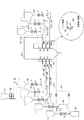
図1に本発明の実施例の粗粉と微粉からなる全体の燃焼系統の主要な構成図を示す。
石炭バンカ37内の50mmアンダーの褐炭は2段の粗粉砕機38で平均粒径数ミリ(例えば、2mm程度)に粉砕され、粗粉となる(詳細は図6参照)。その後、乾燥機39で10〜20%の水分含有量になるまで乾燥され、粗粉ホッパ1に貯留される。
粗粉の系統は粗粉ホッパ1の出口配管に設けられるロータリーバルブ2と燃料遮断弁3があり、それらを通過した粗粉は粗粉混合器5で空気と混合されてボイラ124のバーナ15へと運ばれる。
FIG. 1 shows a main configuration diagram of an entire combustion system composed of coarse powder and fine powder according to an embodiment of the present invention.
The lignite under 50 mm in the
The coarse powder system includes a
一方、粗粒混合器5に代えてミル24を設置し、該ミル24で粗粉ホッパ1内の2mm程度に粉砕される褐炭を微粉炭に粉砕して、ミル出口配管に設けられるロータリーバルブ2と燃料遮断弁3を経由してバーナ15に微粉を送る微粉部があり、同一バーナ15内で粗粉炭と微粉炭を同時に燃焼させる。なお、前記ミル24を常用機として、予備のミル24も設けている。
On the other hand, instead of the
また、図1では表示を省略しているが、石炭バンカ37、粗粉砕機38、乾燥機39の構成を各粗粉ホッパ1ごとに設けている。但し、複数の粗粉ホッパ1で石炭バンカ37、粗粉砕機38及び乾燥機39の構成を共用しても良い。
Although not shown in FIG. 1, the configuration of the
なお、粗粉砕されて乾燥された粗粉のままの褐炭を燃焼させようとすると、固体燃料バーナ15での着火性が低く、継続的に燃焼させることが困難であり、また燃え残りが生じてボイラ124の炉底に落下する燃料の割合が増大するという問題があるが、本発明はそのような問題を解決することもできる。
In addition, when trying to burn the coarsely pulverized and dried coarse lignite, the
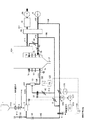
図2は図1で示す粗粉の燃焼系統の詳細な構成図である。ボイラ124にはFDF(押込送風機)6から出た主搬送ガス配管(第1の粗粉用高温搬送ガス配管ともいう)105中の空気をガス予熱器(ボイラ排ガスと燃焼用ガス及び燃料搬送ガスを予熱するもので、一般には空気予熱器:エアヒータと呼ばれる。以下、空気予熱器又はAHと記すこともある。)18を経由してボイラ124のバーナ15とアフターエアポート(AAP)16に予熱空気として供給されて石炭の燃焼に使用される。なお、バーナ15へ通じる主搬送ガス配管105とアフターエアポート(AAP)16へ通じる主搬送ガス配管105にはそれぞれバーナ空気比例制御弁43とアフターエアの酸素制御弁44が設けられている。バーナ空気比例制御弁43と酸素制御弁44の開度は負荷と燃料流量の検出値に基づき制御される。
FIG. 2 is a detailed configuration diagram of the coarse powder combustion system shown in FIG. In the
また、ボイラ124から排出する排ガスは排ガスライン111を通り、ガス予熱器18でFDF6からの空気と熱交換して外部に排出される。空気予熱器18で予熱された空気はバーナ15とアフターエアポート(AAP)16へ供給される石炭燃焼用空気を温める。
また、FDF6の出口の主搬送ガス配管105の冷空気は、空気予熱器18に入る前に分岐して第1の粗粉用低温搬送ガス配管106を通り、第1の粗粉用低温搬送ガス配管106に設けられた搬送用空気流量計9により空気流量を実測し、該実測値と後述する第5の粗粉用高温搬送ガス配管112の熱空気流量を計測する熱空気流量計12の測定値との合計を積算器116で積算し、該積算値とボイラ制御より発信される給炭量要求値(給炭量指令信号)115からの設定空気流量値との偏差を偏差器117で算出し、前記搬送用空気流量計9により計測された実測値が設定空気流量値となるように高値選択器118により第1の粗粉用低温搬送ガス配管106に設けられた搬送用空気流量調整ダンパ7を調整する。
Further, the exhaust gas discharged from the
Further, the cold air in the main
一方、AH(空気予熱器)18から出た空気の一部は主搬送ガス配管105から分岐した第2の粗粉用高温搬送ガス配管109に設けられた搬送用空気温度調整ダンパ8で粗粉混合器5の出口温度が一定になるよう供給量が制御される。搬送用空気温度調整ダンパ8の開度は温度計11で計測された粗粉混合器5の出口温度に基づき制御される。
On the other hand, a part of the air that has exited from the AH (air preheater) 18 is coarsely powdered by the transfer air
また、第1の粗粉用低温搬送ガス配管106中の空気は空気遮断弁10を通過して粗粉混合器5に入る。第2の粗粉用高温搬送ガス配管109の出口は、搬送空気流量調整ダンパ7の設置部より後流側の第1の粗粉用低温搬送ガス配管106に接続している。そして第2の粗粉用高温搬送ガス配管109と第1の粗粉用低温搬送ガス配管106との接続部より後流側の空気流量は搬送空気流量計9で測定される。また搬送空気流量計9より後流側の第1の粗粉用低温搬送ガス配管106にはバーナ15への空気の供給を停止する場合に必要な空気遮断弁10が設けられている。
The air in the first coarse powder low-temperature
また、空気遮断弁10の後流側の第1の粗粉用低温搬送ガス配管106には緊急時に空気の供給を停止する緊急パージ蒸気遮断弁22を備えた緊急パージ蒸気供給配管110が接続している。第1の粗粉用低温搬送ガス配管106の緊急パージ蒸気供給配管110との接続部より後流部に粗粉混合器5が配置され、該粗粉混合器5の後流側には第3の粗粉用高温搬送ガス配管107が設けられ、該第3の粗粉用高温搬送ガス配管107内には約150℃の空気が流れ、熱風混合器13に供給される。該熱風混合器13で加熱されて約250℃となった空気は第4の粗粉用高温搬送ガス配管108を通り、粗粉炭と共にバーナ15に供給される。
なお、粗粉混合器5には粗粉ホッパ1からロータリーバルブ2と燃料遮断弁3を経由して粗粉が供給されることは図1で説明した通りである。
Further, an emergency purge
The coarse powder is supplied from the coarse powder hopper 1 via the
また、搬送用空気温度調整ダンパ8の設置部より前流側の第2の粗粉用高温搬送ガス配管109から分岐した第5の粗粉用高温搬送ガス配管112が熱風混合器13に接続しているので、第5の粗粉用高温搬送ガス配管112から前記熱風混合器13に向けて、該第5の粗粉用高温搬送ガス配管112に設けられた熱風混合ダンパ42の開度を制御しながら高温搬送ガス(空気)が送られる。なお、熱風混合ダンパ42の開度は第4の粗粉用高温搬送ガス配管108に設けられたバーナ入口温度計14で計測された熱風温度の測定値と熱風量指令器123での熱風量指令信号に基づき制御される。また、後述する偏差算出器119で算出される最低空気流量信号と搬送空気流量計9の測定値との偏差を熱風量指令器123にも送信して熱風量指令信号の算出に利用する。
Also, a fifth coarse powder high temperature
ここで、第1の粗粉用低温搬送ガス配管106に配置される空気遮断弁10は、MFT(主燃料遮断)でプラントがトリップした場合に、すばやく閉止して粗粉混合器5とバーナ15との間に残った粗粉を、緊急パージ蒸気遮断弁22を開にして緊急パージ蒸気21をボイラ124の炉内に送り、該緊急パージ蒸気21で炉内をパージすると共に万一、前記粗粉混合器5とバーナ15との間に残った石炭があっても蒸気により酸素濃度を下げることで石炭の発火を抑制する。
Here, the air shut-off
粗粉ホッパ1に貯留された粗粉炭は、粗粉供給配管114に設けられたロータリーバルブ2と燃料遮断弁3を経由して粗粉混合器5に供給される。そしてボイラ124で要求される給炭量に見合うようなロータリーバルブ2の回転数で、その供給量が制御される。燃料遮断弁3はMFT発生時に閉止して燃料を遮断する。一方、粗粉混合器5へ落下する石炭の分だけ粗粉混合器5内の温風が上部に上がってきて、ロータリーバルブ2などの温度が上昇し 石炭が発火する可能性があることからシール空気4を粗粉供給配管114に導入して温風の上昇を抑制する。褐炭中の揮発分は約180℃程度で放散量が急増するので、これより低く保つためにシール空気4の温度を、例えば、150℃程度にする。
Coarse coal stored in the coarse powder hopper 1 is supplied to the
粗粉混合器5を出た粗粉と温風は第3の粗粉用高温搬送ガス配管107を経由して熱風混合器13に入り、さらに温度が上昇する。また、熱風混合器13から第4の粗粉用高温搬送ガス配管108を経由してバーナ15に空気を搬送する。
The coarse powder and hot air that have exited the
熱風混合器13には第2の粗粉用高温搬送ガス配管109から送られた空気予熱器18の出口空気を第5の粗粉用高温搬送ガス配管112に設けた熱風混合ダンパ42の開度を制御して流す。このとき第4の粗粉用高温搬送ガス配管108に設けられたバーナ入口温度測定器14で計測される熱風混合器13からバーナ15に搬送される搬送空気の温度と、熱風量指令信号123の積算値を積算器120で積算して、熱風混合ダンパ42の開度を制御し、バーナ入口温度測定器14で計測したバーナ入口温度が規定温度となるように、第5の粗粉用高温搬送ガス配管112中の分岐空気流量を制御する。なお、熱風量指令器123には最低空気流量信号と搬送空気流量計9の測定値との偏差を算出する偏差算出器119からの信号が送られる。例えば、第4の粗粉用高温搬送ガス配管108内の250℃の熱風が1〜2秒でバーナ15に達する程度の前記配管108の長さを、例えば15〜30mとすることで、褐炭中の揮発分が丁度放散されてきて燃焼しやすくなる。
In the
また、第1の粗粉用低温搬送ガス配管106にある搬送空気流量調整ダンパ7は、給炭量要求値に対して熱風混合器13に投入される空気量と粗粉混合器5に入る空気の合計量を制御するが、熱風混合器13に入る空気量が多量となっても最低限、粗粉搬送に必要な空気は確保するように、粗粉混合器5出口の搬送空気温度を温度計11で計測し、その結果に基づき搬送空気温度調整ダンパ8の開度を制御して粗粉混合器5に流入する粗粉用低温搬送ガス(空気)流量を制御する。
Further, the carrier air flow
また、実空気量が前記粗粉搬送に最低限必要な空気量に近づくと、熱風混合ダンパ42の開度を下げるようにバーナ入口温度計14の設定温度を下げてバーナ15の石炭濃度が必要以上低下しないよう制御する。
すなわち、搬送する石炭の量が低下すると空気もそれに見合って低下するが、石炭の搬送配管内での停滞を防止するために最低流量の空気を投入する必要がある。この場合、バーナ15へ入る前の空気温度設定が高いままだと、さらに空気を混合器13より投入することとなり、石炭に対する空気の比率が増すことで石炭濃度が低下し(薄くなり)、最悪失火することから、これを防止するために温度設定を下げ熱風混合器13への熱空気投入量を制限する。
Further, when the actual air amount approaches the minimum air amount necessary for the coarse powder conveyance, the set temperature of the burner inlet thermometer 14 is lowered so that the opening degree of the hot
That is, when the amount of coal to be transported decreases, the air also correspondingly decreases. However, in order to prevent stagnation of the coal in the transport piping, it is necessary to introduce air at the minimum flow rate. In this case, if the air temperature setting before entering the
バーナ15に投入された粗粉は高温でガス化し、燃焼し易い状態となるが粒径の大きい(数ミリの)粒子の一部はボイラ124の炉底に落下する。炉底に落下した石炭は置き火燃焼用コンベア17で燃焼しつつ灰と共に系外に運ばれる。
The coarse powder charged into the
ボイラ124の炉内に入った粗粉子はAAP16で完全燃焼してボイラ124内で熱交換した後、空気予熱器18と電気集塵機19を通り、IDF(誘引送風機)20で煙突(図示せず)に運ばれる。
The coarse powder particles that enter the furnace of the
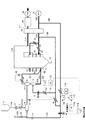
図3は微粉の燃焼系統図を示す。
前述した図2の粗粉の燃焼系統と異なるのは、図2の粗粉混合器5の代わりに粗粉を微粉にするためのミル(微粉砕機)24を設置したこと、及び前記ミル24での圧力損失分を補うために第1の微粉用低温搬送ガス配管106’の空気遮断弁10’の前流側に一次空気ファン23を設置したこと、及び図2の熱風混合器13が設置されておらず、また熱風混合器13に熱風を送る第5の粗粉用高温搬送ガス配管112及びそれに関連する機器は設置していないことである。
図3の微粉の燃焼系統図で図2の熱風混合器13が設置されていない理由は、ミル24によって微粉炭が得られるので熱混合器13を設置しなくてもバーナ15の保炎性には問題がないためである。
FIG. 3 shows a combustion system diagram of fine powder.
2 differs from the coarse powder combustion system of FIG. 2 described above in that instead of the
The reason why the
なお、図2の粗粉の燃焼系統図の搬送ガス配管に対応する図3の微粉の燃焼系統図の搬送ガス配管にはそれぞれ対応する数字にダッシュ符号を付し、説明を省略することがある。例えば、図2の第1の粗粉用低温搬送ガス配管106又は主搬送ガス配管105と類似した図3の微粉の燃焼系統図の第1の微粉用低温搬送ガス配管106’又は主搬送ガス配管(第1の微粉用高温搬送ガス配管ともいう)105’には数字にダッシュ符号を付している。
また、粗粉はバーナ15ごとに供給するのに対して微粉は一台のミル24で全てのバーナ15に供給することができる。ただし、予備のミル24を設置し、合わせて2台のミル24としても良い。
The carrier gas piping in the combustion system diagram of fine powder in FIG. 3 corresponding to the carrier gas piping in the combustion system diagram of coarse powder in FIG. . For example, a first coarse powder for the low-temperature
The coarse powder is supplied for each
ガス予熱器(AH)18の入口の主搬送ガス配管105’中の一部の空気を微粉炭の搬送用空気として第1の微粉用低温搬送ガス配管106’に分岐して供給し、搬送空気流量調整ダンパ7’で一次空気流量計9’の値が給炭指令に見合う空気量となるよう制御される。すなわち第1の微粉用低温搬送ガス配管106’に設けられた搬送用空気流量調整ダンパ7’と搬送用空気流量計9’により空気流量を実測し、該実測値とボイラ制御より発信される給炭量要求値(給炭量指令信号)115’からの設定空気流量値の偏差を偏差器117’で算出し、前記実測値が設定空気流量値となるように高値選択器118’により搬送用空気流量調整ダンパ7’を調整する。
Gas preheater (AH) 18 inlet of supply branches 'part of the air in the first fine powder for the low-temperature
一方、ガス予熱器18の出口の主搬送ガス配管105’中の温風は主搬送ガス配管105’から分岐して設けられる第2の微粉用高温搬送ガス配管109’から第1の微粉用低温搬送ガス配管106’を経由してミル24に供給されるが、ミル24の出口温度計27で測定される出口温度が設定値となるように、第2の微粉用高温搬送ガス配管109’の搬送空気温度調整ダンパ8’で第2の微粉用高温搬送ガス配管109’中の空気(温風)量を制御する。ミル24入口の第1の微粉用低温搬送ガス配管106’中の空気温度は温度計28で測定されるが、ミル24の入口の空気温度が必要以上に高くならないように、該温度計28で測定されるミル入口温度で制御温度にバイアスを掛ける機能を有している。
すなわち、ミル24の入口温度を高くし過ぎると、石炭中の揮発分がガス化して可燃性ガスとなり危険な状態となるため、入口温度が150℃を超える場合はミル出口温度にバイアスを設けて150℃を超えないようにする。
On the other hand, the first fine powder from and a second fine powder for high temperature
That is, if the inlet temperature of the
これは第1の微粉用低温搬送ガス配管106’の空気遮断弁10’の前流側に設けられる一次空気ファン23の前流側の第1の微粉用低温搬送ガス配管106’の空気温度をミル入口温度計28で計測し、該ミル入口温度計測値が150℃以下の温度設定指令器121の指令値とミル出口温度計27の測定値の合計値を積算器122で算出して搬送空気温度調節ダンパ8’の開度を制御する。
また第1の微粉用低温搬送ガス配管106’中の搬送用空気は一次空気ファン23に入り、昇圧されて空気遮断弁10の通過後にミル24に供給される。
Air This first fine powder for the low-temperature
The conveying air in the first in the fine powder for the low-temperature carrier gas pipe 106 'enters the
粗粉ホッパ1から要求量に見合う量が粗粉供給配管114に配置されるロータリーバルブ2の回転制御によりミル24内に供給された粗粉石炭はミル24の粉砕部で微粉化されて第3の微粉用高温搬送ガス配管107’を経由して各バーナ15へ供給される。各段のバーナ15の直前の第3の微粉用高温搬送ガス配管107’にはミル出口ダンパ40が設置され、バーナ段ごとのオン/オフを可能にしている。
Coarse coal supplied into the
第3の微粉用高温搬送ガス配管107’に設けられるミル出口ダンパ40の閉止時からバーナ15までに存在する微粉は第1の微粉用低温搬送ガス配管106’から分岐された分岐低温搬送ガス配管113に設けられたパージ弁26により空気予熱器18の前流側の冷空気を供給してパージする。また、図1の丸枠内にバーナ15の手前の第3の微粉用高温搬送ガス配管107’と分岐低温搬送ガス配管113との合流部の一部を拡大図で示したように、分岐低温搬送ガス配管113内の低温搬送ガス(冷空気)を第3の微粉用高温搬送ガス配管107’内の高温ガスに投入可能な流路構成ができている。
Third fine powder for high temperature carrier gas pipe 107 'fines present in up to the
図4は粗粉燃焼バーナの一例を示すバーナ断面図である。
バーナ15の中央の一次燃料ノズル45に粗粉と一次空気(搬送空気)の混合流が入り、ベンチュリ29で前記混合流に絞りを入れることで均一化された石炭粗粉がバーナ15の先端へ供給される。一方、微粉と一次空気の混合流は前記一次燃料ノズル45の外周部に設けられた二次燃料ノズル49に供給され、保炎リング35の直前でバーナ15の先端部に噴出される。微粉は保炎リング35の後方で巻き返し、安定した火炎を形成し、微粉より内側にある粗粉を蒸し焼きにすることで粗粉子もガス化し、燃焼され易くなる。
FIG. 4 is a burner cross-sectional view showing an example of a coarse powder combustion burner.
A mixed flow of coarse powder and primary air (carrier air) enters the
バーナ15へ供給する空気は二次燃料ノズル49の外側に配置される二次空気ノズル50内を流れる二次空気流30と二次空気ノズル50の外側に配置される三次空気ノズル51内を流れる三次空気流32とにそれぞれ分けられ、二次空気ノズル50内の二次ベーン31と三次空気ノズル51内に配置される三次レジスタ33などによる調整で炉内での燃料の保炎性、燃焼排ガス中のNOx濃度、酸素分布などの調整が可能になっている。
空気が燃焼の初期段階で過剰に供給されるとNOx濃度の上昇を招くことからバーナ15の先端部は燃焼用空気を外向きに拡大して流すガイドスリーブ34を設けて空気が固体燃料燃焼時に過剰に供給されるのを抑制している。
また、バーナ15の中央には起動時及び非常時用の油バーナ36を設置可能にしている。
The air supplied to the
If air is excessively supplied at the initial stage of combustion, the NOx concentration is increased. Therefore, the tip of the
An
なお、粗粉用の低温の搬送ガス配管である第1の粗粉用低温搬送ガス配管106と微粉用の低温搬送ガス配管である第1の微粉用低温搬送ガス配管106’は、それぞれ粗粉混合器5と一次空気ファン23の手前のいずれかの部位まで共通するものであっても良い。 同様に第4の粗粉用高温搬送ガス配管108に接続するまでの第3の粗粉用高温搬送ガス配管107と第3の微粉用高温搬送ガス配管107’は粗粉用と微粉用とで共用しても良い。
Incidentally, a cold carrier gas piping for coarse powder first coarse powder for the low-temperature
要するに微粉用の搬送ガス系統(微粉供給系統)においては、微粉が第3の微粉用高温搬送ガス配管107’から系内に導入された後のガス温度が揮発分の多い褐炭の自然発火を防いで安全に気流搬送させる観点から、例えば70℃程度を上限として制御されれば良い。 In short, in the carrier gas system for fine powder (fine powder supply system), the gas temperature after the fine powder is introduced into the system from the third high-temperature carrier gas pipe 107 'for fine powder prevents spontaneous combustion of lignite with a high volatile content. For example, from the viewpoint of safely carrying the air current, the upper limit may be controlled, for example, at about 70 ° C.
同じく、粗粉用の搬送ガス系統においては、粗粉が第3の粗粉用高温搬送ガス配管107から系内に導入された直後のガス温度は、同様の観点から、例えば150℃に抑制され、燃焼させるバーナ15の直前において250℃に昇温されることで、安全性を確保しながら、ボイラ効率を高めることができる。
Similarly, in the carrier gas system for coarse powder, the gas temperature immediately after the coarse powder is introduced into the system from the third high-temperature
図5は、粗粉中に微粉が多く含まれている場合に適用できる燃焼系統図を示す。
粗粉中に微粉が多い場合は微粉の燃焼系統に配置する微粉炭機24の設置を省略して、サイクロンセパレータ41で分離した微粉を使用しても良い。
FIG. 5 shows a combustion system diagram applicable when coarse powder contains a lot of fine powder.
If the coarse powder contains a lot of fine powder, the fine powder separated by the
粗粉混合器5から出た粗粉と空気はサイクロンセパレータ41で分離され、軽い微粉はサイクロンセパレータ41の上部に移動し、微粉搬送配管46に設けられた微粉圧調整ダンパ47を、同じく微粉搬送配管46の微粉圧調整ダンパ47より後流側に設けられた微粉圧力計48で計測される圧力に基づいて開度が調整される。また微粉圧調整ダンパ42で必要量が取り出されて図示しない配管を経由して保炎リング35(図4)近傍に送られる。
一方、粗粉はサイクロンセパレータ41の下部より抜出されて熱風混合器13に送られる。
Coarse powder and air discharged from the
On the other hand, the coarse powder is extracted from the lower part of the
次に本発明の前記実施例に使用される実施形態を図面と共に説明する。先ず、乾燥コンベア装置の構成について説明する。
(乾燥コンベア装置の構成)
図6は、本発明の実施形態に係る乾燥コンベア装置全体の系統図である。
この乾燥コンベア装置は同図に示すように、乾燥コンベア装置本体39と、その乾燥コンベア装置本体39に、例えば石炭(褐炭)などの未乾燥の粗粒子52を供給する粗粒子供給手段53と、乾燥コンベア装置本体39に乾燥用の温風を供給する温風供給手段54と、飛散した乾燥済みの微粒子を捕集する飛散粒子捕集手段55とから主に構成されている。
前記乾燥コンベア装置本体39の構成などについては、後で説明する。
Next, an embodiment used in the above-described embodiment of the present invention will be described with reference to the drawings. First, the configuration of the drying conveyor device will be described.
(Configuration of drying conveyor)
FIG. 6 is a system diagram of the entire drying conveyor apparatus according to the embodiment of the present invention.
As shown in the figure, the drying conveyor device includes a drying conveyor device
The configuration of the drying conveyor device
前記粗粒子供給手段53は、粗粒子52に粉砕する前の原料56を貯留する原料サイロ37と、その下に設けられて前記原料56を所定の大きさに粉砕する粉砕機38と、粉砕されて生成した粗粒子52を貯留する乾燥前ホッパ59と、その下に設けられた第1のゲート弁60と、その下に設けられた第2のゲート弁61と、前記第1のゲート弁60と第2のゲート弁61の間に設けられた計量管部62(図7参照)とを備えている。
The coarse particle supply means 53 includes a
図7に示すように、前記第1のゲート弁60ならびに第2のゲート弁61は、それぞれシリンダ63で個別に駆動できるようになっている。また、前記計量管部62の下端部は、乾燥コンベア装置本体39(後述のハウジング70)内に挿入されている(図7参照)。
As shown in FIG. 7, the
前記温風供給手段54は、吸引ダンパ64と送風機65と熱交換器66とを備え、熱交換器66に供給された空気は例えば蒸気タービン(図示せず)から抽気した蒸気などによって加熱される。
前記飛散粒子捕集手段55は、サイクロンセパレータ68と、その下に設けられたロータリーシール69を有している。
The hot air supply means 54 includes a
The scattered particle collecting means 55 has a
図7は前記乾燥コンベア装置本体39の概略構成図、図8はその乾燥コンベア装置本体39に用いるエプロンの斜視図、図9は図7のA−A線上の拡大断面図、図10は図7のB−B線上の拡大断面図、図11はエプロンの配置状態を示す概略側面図である。
7 is a schematic configuration diagram of the drying conveyor apparatus
この乾燥コンベア装置本体39は、粗粒子52の搬送方向に沿って延びたハウジング70の内側の高さ方向の略中間位置に、エプロンコンベア71が配置されている。このハウジング70は、エプロンコンベア71を格納して外気と遮断されている。前記エプロンコンベア71は、所定の間隔をおいて配置された駆動プーリ72とテンションプーリ(従動プーリ)73の間に張架されている。エプロンコンベア71の張力はテンションプーリ73に付設されたテンション設定器74によって設定でき、これによってエプロンコンベア71の伸びや蛇行の調整ができる。
In the drying conveyor device
エプロンコンベア71はチェーンコンベアから構成されており、その上には多数のエプロン75が整列して、回動可能に取り付けられている。このエプロン75は図8に示すように、底板76と、その底板76のエプロン75の移動方向下流側端部から立設した背面板77と、補強のために底板76と背面板77を両側面から連結した側面形状が略三角形をした補強板78a,78bを有している。
The
このエプロン75の移動方向上流側と、左右側面の大半と、上方が解放されている。図8〜図11に示すように、前記エプロン75の移動方向上流側は、隣接する1つ前のエプロン75の背面板77で塞がれる。エプロン75の左右側面は、その左右側面に対応するようにハウジング70内に設けられた板状の吹き抜け防止部材91a,91bによって覆われている。この吹き抜け防止部材91は図7や図11に示すように、駆動プーリ72とテンションプーリ73の間隔と略同じ長さ延びている。なお、図8では図面が複雑になるため、手前側の吹き抜け防止部材91bの図示を省略している。
The upstream side of the
前記底板76と、その底板76から立設した背面板77と、隣接する1つ前のエプロン75の背面板77と、吹き抜け防止部材91a,91bによって、エプロン75の内側に粗粒子52を収容する収容空間82(図9)が形成される。図9や図10に示すように、吹き抜け防止部材91a,91bの上端部は開放状態になっている。
前記底板76には、多数の温風吹き出し孔79が形成されている。本実施形態では底板76として、多数の温風吹き出し孔79を形成したパンチングプレートを使用したが、金網などでもよい。さらに図9に示すように各エプロン75の左側の補強板78aの下端部近くには、エプロン75の到来を検出するための被検出部81が設けられている。また、エプロン75が計量管部62の下に来たことを検出するための位置センサー93が、エプロン75(被検出部81)の近くに固定されている。
A large number of hot air blowing holes 79 are formed in the
本実施形態の場合、テンションプーリ73が配置されている側が粗粒子52の供給側、駆動プーリ72が配置されている側が粗粒子52の排出側となっており、粗粒子52はテンションプーリ73から駆動プーリ72の方向に間欠的に搬送され、矢印Xがその搬送方向を示している。
In the present embodiment, the side on which the
そのため図7に示すように、テンションプーリ73の上方のハウジング部分では、前記粗粒子供給手段53の計量管部62の下端部が貫通して、エプロン75近くまで延びている。一方、駆動プーリ72の下方のハウジング部分には、乾燥済みの粗粒子52の排出口83が形成されている。
Therefore, as shown in FIG. 7, in the housing portion above the
後述するように前記計量管部62の下端部から粗粒子52を落下して、前記エプロン75の収容空間82に収容するとき、粗粒子52の一部がエプロン75の温風吹き出し孔79からエプロンコンベア71内に落下することがある。これを防止するため、図7ならびに図9に示すように、計量管部62の下側に来たエプロン75の温風吹き出し孔79を塞ぐための供給側閉塞板84aが、エプロン75の下に設置されている。また、駆動プーリ72の近傍にも、粗粒子52が温風吹き出し孔79から落下するのを防止するための排出側閉塞板84bが設置されている。
As will be described later, when the
図7に示すように、供給側閉塞板84aと排出側閉塞板84bの間には、粗粒子52の搬送方向Xに沿って複数個の風箱85がエプロン75の下側に連続して設置されている。風箱85は図10に示すように、一方の端に向けて低く傾斜した底板86と、その底板86から立設した両側板87a,87bと、短い方の側板87aに取り付けられた温風導入管88を有し、風箱85の上方開口部はエプロン75の底板76と対向している。
As shown in FIG. 7, a plurality of
前記温風導入管88を有する短い方の側板87aとは反対側の長い方の側板87bの下端部付近あるいは底板86の低い方の端部には、落下粒子排出孔89が設けられている。また、図6に示すように、各風箱85の温風導入管88には前記温風供給手段54から延びた温風供給管90がそれぞれ接続されている。
Falling particle discharge holes 89 are provided in the vicinity of the lower end of the
さらにハウジング70の内側底面上には、清掃用チェーンコンベア94がハウジング70の長手方向に沿って配置されている。この清掃用チェーンコンベア94は駆動プーリ95と従動プーリ96によって、ハウジング70の内側底面を掃くように常時あるいは所定の時間間隔で矢印Y方向に回転駆動される。
Further, on the inner bottom surface of the
本実施形態では、ハウジング70の内側底面が水平状態になっているが、ハウジング70の内側底面を排出口83側に向けて若干低く傾斜するように設けると、前記清掃用チェーンコンベア94による清掃効率が良好になる。
In the present embodiment, the inner bottom surface of the
図7に示すように、ハウジング70の上面部には、サイクロンセパレータ68側に延びる微粒子捕集配管97が接続されている。一方、ロータリーシール69から延びた微粒子送り配管98は、ハウジング70の外から排出口83側に延びている。
As shown in FIG. 7, a fine
次にこの乾燥コンベア装置の動作について説明する。
(乾燥コンベア装置の動作)
図6に示すように、原料サイロ37に貯留されている例えば水分含有率が40〜50重量%程度の褐炭からなる原料56が粉砕機38で粉砕されて、粒子の大きさが1mm程度の粗粒子52となり、乾燥前ホッパ59に貯留されている。そして、下側の第2のゲート弁61を閉じた状態で上側の第1のゲート弁60を開けると、乾燥前ホッパ59内の粗粒子52の一部が第1のゲート弁60を通り、計量管部62(図7参照)内に充填され、計量管部62の容積に相当する粗粒子52の計量がなされる。計量管部62内に粗粒子52を充填した後、第1のゲート弁60を閉じる。これらゲート弁60,61の開閉動作は、個別に付設されたシリンダ63(図7参照)によってなされる。
Next, operation | movement of this drying conveyor apparatus is demonstrated.
(Operation of drying conveyor)
As shown in FIG. 6, a
エプロンコンベア71は図7に示すように、搬送方向Xに間欠的若しくは連続的に周回移動しており、図9に示すように、計量管部62の下側にエプロン75が来たことをエプロン75に付設された被検出部81と位置センサー93の共働で検出する。エプロン75が計量管部62の下側に来たときには、図9に示すように当該エプロン75の全ての温風吹き出し孔79は供給側閉塞板84で塞がれている。
As shown in FIG. 7, the
この状態で前記第2のゲート弁61を開くと、計量管部62内に貯留されていた粗粒子52がエプロン75の収容空間82内に落下する。粗粒子62の落下後、第2のゲート弁61は自動的に閉じ、次の計量に備えられる。前述のようにエプロン75の温風吹き出し孔79は閉塞板84で塞がれているから、投入された粗粒子52が温風吹き出し孔79から落ちることはなく、計測量が適正に維持されている。
When the
図9は、このように計量して切り出された粗粒子52をエプロン75内に収容した状態を示しており、この時点ではエプロン75内には後述する温風99は吹き込まれていないので、粗粒子52によって形成された層は静止層になっており、収容空間82の上部には十分な空間部100が残っている。
FIG. 9 shows a state in which the
図6ならびに図10に示すように、温風供給手段54(図6参照)によって生成、供給された温風99は各風箱85に吹き込まれている(図10参照)。一方、前記エプロン75の移動に伴ってそれの底板76に形成されている温風吹き出し孔79が閉塞板84を通過すると風箱85内で温風吹き出し孔79が開放され、風箱85内に導入された温風99がエプロン75の底部から吹き込み、粗粒子52が流動化状態(矢印101とする)となり始める。単純に温風99が粗粒子52の間を通過するだけでは粗粒子52の一面だけしか乾燥されないが、本実施形態のように粗粒子52を浮かせて無方向、不規則状に流動化状態(矢印101)とすることにより、粗粒子52の全面を均一にかつ迅速に乾燥させることができる。
流動化して吹き上がった粗粒子52がエプロン75から吹き出ないように、前記吹き抜け防止部材91a,91bが設けられている。
As shown in FIGS. 6 and 10, the
The blow-through preventing
乾燥する過程で粗粒子52は比重が徐々に低下して軽くなるので、図7に示すように風箱85は粗粒子52の搬送方向Xに沿って複数に分割され、粗粒子52の比重に見合って温風99の風量の調整がなされている。この温風99の調整をしないと、乾燥途中で粗粒子52の一部が風箱85から吹き出して落下したり、自然発火の危険があるため好ましくない。
Since the specific gravity of the
粗粒子52は複数の風箱85の上を通過することにより所望の水分含有率(本実施例に係る褐炭の場合は、5〜10重量%程度)まで乾燥され、図7に示すようにエプロン75が駆動プーリ72の周囲を上側から下側に回るときに自動的に傾倒されて、最終的には逆さまの状態になるので、乾燥された粗粒子52は排出口83側に落下して、ハウジング70から取り出される。
The
図7に示すように、駆動プーリ72の斜め下方には、エプロン75に残っている粗粒子52があるとそれを強制的に吹き落とすための複数本の空気噴出ノズル92が設けられている。そして逆さになったエプロン75がこの空気噴出ノズル92の下を通過するようになっており、空気噴出ノズル92から高速噴射された空気は、エプロン75の底板76に形成されている温風吹き出し孔79を通って、エプロン75内に付着している粗粒子52を吹き落とす。この空気の高速噴射は、温風吹き出し孔79ならびにエプロン75の内面の清掃も兼ねており、エプロン75内での粗粒子52の適正な流動化状態を常に維持することができる。
As shown in FIG. 7, a plurality of air ejection nozzles 92 for forcibly blowing
このようにしてハウジング70の底面に落ちた粗粒子52、あるいは風箱85の落下粒子排出孔89からハウジング70の底面に落ちた粗粒子52は、清掃用チェーンコンベア94により排出口83側に掃き出される。前記風箱85の落下粒子排出孔89からハウジング70の底面に落ちる粗粒子52も温風99と十分に接触して乾燥しているため、他の乾燥した粗粒子52と一緒に排出口83から排出しても構わない。
The
一方、温風99により舞い上がった微粒子は微粒子捕集配管97を通ってサイクロンセパレータ68で捕集され、ロータリーシール69を経て、微粒子送り配管98によりハウジング70の排出口83側に送られる。なお、温風99により舞い上がった微粒子は粗粒子52に比べて乾燥時間が速いため、サイクロンセパレータ68へ搬送される過程で乾燥は完了しているので、微粒子送り配管98から直接排出して、他の乾燥した粗粒子52と混合しても支障はない。
On the other hand, the fine particles soared by the
図7に示すように、最終の風箱85(図7において右端の風箱85)を駆動プーリ72に隣接することは構造上難しいため、最終の風箱85と駆動プーリ72の間には必然的に隙間ができる。そのため本実施形態では、最終の風箱85と駆動プーリ72の間に排出側閉塞板84bを設置して、その間を通るエプロン75の温風吹き出し孔79を塞ぐことにより、乾燥された粗粒子52が駆動プーリ72の近辺に落下することを防止している。
As shown in FIG. 7, it is structurally difficult to place the final wind box 85 (the
1 粗粒ホッパ 2 ロータリーバルブ
3 燃料遮断弁 4 シール空気
5 粗粉混合器 6 FDF(押込送風機)
7,7’ 搬送空気流量調整ダンパ 8,8’ 搬送空気温度調整ダンパ
9,9’ 搬送空気流量 10,10’ 空気遮断弁
11 混合器出口温度 12 熱空気流量計
13 熱風混合器 14 バーナ入口温度
15 バーナ 16 AAP(アフターエアポート)
17 置き火燃焼用コンベア 18 ガス予熱器(エアヒータ;AH)
19 EP(電気集塵機) 20 IDF(誘引送風機)
21 緊急パージ蒸気 22 緊急パージ蒸気遮断弁
23 一次空気ファン 24 ミル(微粉砕機)
26 パージ弁 27 ミル出口温度
28 ミル入口温度 29 ベンチュリ
30 二次空気 31 二次ベーン
32 三次空気 33 三次レジスタ
34 ガイドスリーブ 35 保炎リング
36 油バーナ 37 石炭バンカ
38 粗粉砕機 39 乾燥機
40 ミル出口ダンパ 41 サイクロンセパレータ
42 熱風混合ダンパ 43 バーナ空気比例制御弁
44 酸素制御弁 45 一次燃料ノズル
46 微粉搬送配管 47 微粉圧調整ダンパ
48 微粉圧力計 49 二次燃料ノズル
50 二次空気ノズル 51 三次空気ノズル
52 粗粒子 53 粗粒子供給手段
54 温風供給手段 55 飛散粒子捕集手段
56 原料 59 乾燥前ホッパ
60 第1のゲート弁 61 第2のゲート弁
62 計量管部 63 シリンダ
64 吸引ダンパ 65 送風機
66 熱交換器 68 サイクロンセパレータ
69 ロータリーシール 70 ハウジング
71 エプロンコンベア 72 駆動プーリ
73 テンションプーリ(従動プーリ) 74 設定器
75 エプロン 76 底板
77 背面板 78a,78b 補強板
79 温風吹き出し孔 81 被検出部
82 収容空間 83 排出口
84a 供給側閉塞板 84b 排出側閉塞板
85,85a,85b,85c,85d 風箱
86 底板 87a,87b 側板
88 温風導入管 89 落下粒子排出孔
90 温風供給管 91a,91b 吹き抜け防止部材
92 空気噴出ノズル 93 位置センサー
94 清掃用チェーンコンベア 95 駆動プーリ
96 従動プーリ 97 微粒子捕集配管
98 微粒子戻し配管 99 温風
100 空間部
105,105’ 主搬送ガス配管(第1の粗粉、微粉用高温搬送ガス配管)
106,106’ 第1の粗粉、微粉用低温搬送ガス配管
107,107’ 第3の粗粉、微粉用高温搬送ガス配管
108 第4の粗粉用高温搬送ガス配管
109,109’ 第2の粗粉、微粉用高温搬送ガス配管
110,110’ 緊急パージ蒸気配管
111,111’ 排ガスライン
112 第5の粗粉用高温搬送ガス配管
113 分岐低温搬送ガス配管 114 粗粉供給配管
115,115’ 給炭量要求値(給炭量指令信号)
116 積算器 117,117’ 偏差器
118,118’ 高値選択器又はその信号
119,119’ 偏差算出器 120 積算器
121 温度設定指令器 122 積算器
123 熱風量指令器 124 ボイラ
DESCRIPTION OF SYMBOLS 1
7, 7 'Conveyance air flow
17 Conveyor for
19 EP (electric dust collector) 20 IDF (attracting blower)
21
23
26 Purge valve 27 Mill outlet temperature 28 Mill inlet temperature 29 Venturi 30 Secondary air 31 Secondary vane 32 Tertiary air 33 Tertiary resistor 34 Guide sleeve 35 Flame holding ring 36 Oil burner 37 Coal bunker 38 Coarse grinder 39 Dryer 40 Mill outlet Damper 41 Cyclone Separator 42 Hot Air Mixing Damper 43 Burner Air Proportional Control Valve 44 Oxygen Control Valve 45 Primary Fuel Nozzle 46 Fine Powder Transfer Piping 47 Fine Powder Pressure Adjustment Damper 48 Fine Powder Pressure Gauge 49 Secondary Fuel Nozzle 50 Secondary Air Nozzle 51 Secondary Air Nozzle 52 Coarse particles 53 Coarse particle supply means 54 Hot air supply means 55 Scattered particle collection means 56 Raw material 59 Pre-drying hopper 60 First gate valve 61 Second gate valve 62 Metering pipe section 63 Cylinder 64 Suction damper 65 Blower 66 Heat exchange 68 cyclone separator 69 b -Tally seal 70 Housing 71 Apron conveyor 72 Drive pulley 73 Tension pulley (driven pulley) 74 Setting device 75 Apron 76 Bottom plate 77 Back plate 78a, 78b Reinforcement plate 79 Hot air blowing hole 81 Detected portion 82 Storage space 83 Discharge port 84a Supply side blockage Plate 84b Discharge side blocking plates 85, 85a, 85b, 85c, 85d Wind box 86 Bottom plate 87a, 87b Side plate 88 Hot air introduction pipe 89 Falling particle discharge hole 90 Hot air supply pipe 91a, 91b Blow-through prevention member 92 Air jet nozzle 93 Position Sensor 94 Cleaning chain conveyor 95 Drive pulley 96 Driven pulley 97 Particulate collection pipe 98 Particulate return pipe 99 Hot air 100 Space
105, 105 'main carrier gas piping (first coarse powder, high temperature carrier gas piping for fine powder)
106, 106 ′ first coarse powder , fine powder low temperature
Claims (6)
各固体燃料バーナ(15)には、固体燃料の粗粉と微粉とをそれぞれ別系統で導入して燃焼させるための、粗粉供給系統と微粉供給系統とが接続されており、
前記粗粉供給系統は、
前記ガス予熱器(18)を経由して固体燃料搬送ガスを前記固体燃料バーナ(15)に導入する第1の粗粉用高温搬送ガス配管(105)と、
前記ガス予熱器(18)の前流側で前記第1の粗粉用高温搬送ガス配管(105)から分岐した第1の粗粉用低温搬送ガス配管(106)と、
前記ガス予熱器(18)の後流側で前記第1の粗粉用高温搬送ガス配管(105)から分岐して前記第1の粗粉用低温搬送ガス配管(106)に接続される第2の粗粉用高温搬送ガス配管(109)と、
該第2の粗粉用高温搬送ガス配管(109)を前記第1の粗粉用低温搬送ガス配管(106)に接続した接続部の後流側に設けられる固体燃料の粗粉を混合するための粗粉混合器(5)と、
該粗粉混合器(5)から固体燃料バーナ(15)に粗粉を供給する第3、4の粗粉用高温搬送ガス配管(107,108)とを備え、
前記微粉供給系統は、
前記ガス予熱器(18)を経由して固体燃料搬送ガスを前記固体燃料バーナ(15)に導入する第1の微粉用高温搬送ガス配管(105’)と、
前記ガス予熱器(18)の前流側で前記第1の微粉用高温搬送ガス配管(105’)から分岐した第1の微粉用低温搬送ガス配管(106’)と、
前記ガス予熱器(18)の後流側で前記第1の微粉用高温搬送ガス配管(105’)から分岐して前記第1の微粉用低温搬送ガス配管(106’)に接続される第2の微粉用高温搬送ガス配管(109’)と、
該第2の微粉用高温搬送ガス配管(109’)を前記第1の微粉用低温搬送ガス配管(106’)に接続した接続部の後流側の第1の微粉用低温搬送ガス配管(106’)に設けられる搬送ガスファン(23)と、
搬送ガスファン(23)の後流側の前記第1の微粉用低温搬送ガス配管(106’)に接続した固体燃料の粗粉を微粉砕して前記固体燃料の微粉を生成し、搬送ガス流に供給する微粉砕機(24)と、
該微粉砕機(24)から固体燃料バーナ(15)に微粉を供給する第3の微粉用高温搬送ガス配管(107’)と
を備え、
前記粗粉供給系統は、前記粗粉混合器(5)が前記複数のバーナグループ(15,15,・・・)それぞれに対応して複数個設けられ、前記微粉供給系統は、前記微粉砕機(24)が前記複数のバーナグループ(15,15,・・・)に対して少なくとも1機設けられていることを特徴とする固体燃料ボイラシステム。 The solid fuel boiler (124) having a plurality of burner groups each including two or more solid fuel burners (15, 15,...), And the exhaust gas, combustion gas, and carrier gas from the boiler (124) are heated. A solid fuel boiler system having a gas preheater (18) to be replaced,
Each solid fuel burner (15) is connected with a coarse powder supply system and a fine powder supply system for introducing and burning solid fuel coarse powder and fine powder in separate systems.
The coarse powder supply system is
A first coarse powder high-temperature carrier gas pipe (105) for introducing a solid fuel carrier gas into the solid fuel burner (15) via the gas preheater (18);
A first coarse powder low temperature carrier gas pipe (106) branched from the first coarse powder high temperature carrier gas pipe (105) on the upstream side of the gas preheater (18);
A second branch branched from the first coarse powder high temperature carrier gas pipe (105) on the downstream side of the gas preheater (18) and connected to the first coarse powder cold carrier gas pipe (106). High-temperature carrier gas pipe (109) for coarse powder,
In order to mix the coarse powder of solid fuel provided on the downstream side of the connecting portion where the second coarse powder high temperature carrier gas pipe (109) is connected to the first coarse powder low temperature carrier gas pipe (106). Coarse powder mixer (5),
Third and fourth coarse powder high-temperature carrier gas pipes (107, 108) for supplying coarse powder from the coarse powder mixer (5) to the solid fuel burner (15),
The fine powder supply system is
A first high-temperature carrier gas pipe for fine powder (105 ′) for introducing a solid fuel carrier gas into the solid fuel burner (15) via the gas preheater (18);
A first fine powder low temperature carrier gas pipe (106 ′) branched from the first fine powder high temperature carrier gas pipe (105 ′) on the upstream side of the gas preheater (18);
A second branch branched from the first high-temperature carrier gas pipe (105 ′) for fine powder and connected to the first low-temperature carrier gas pipe (106 ′) for fine powder on the downstream side of the gas preheater (18). High-temperature carrier gas pipe (109 ') for fine powder,
The first low-temperature carrier gas pipe for the fine powder (106 on the downstream side of the connecting portion where the second high-temperature carrier gas pipe for the fine powder (109 ′) is connected to the first low-temperature carrier gas pipe (106 ′) for the fine powder. A carrier gas fan (23) provided in ');
The solid fuel coarse powder connected to the first low-temperature carrier gas pipe (106 ′) for the fine powder on the downstream side of the carrier gas fan (23) is finely pulverized to produce the fine powder of the solid fuel. A fine pulverizer (24) to be supplied to
A third high-temperature carrier gas pipe (107 ′) for supplying fine powder from the fine grinder (24) to the solid fuel burner (15),
The coarse powder supply system includes a plurality of the coarse powder mixers (5) corresponding to the plurality of burner groups (15, 15,...), And the fine powder supply system includes the fine pulverizer. (24) is provided with at least one unit for the plurality of burner groups (15, 15,...).
該第2の粗粉用高温搬送ガス配管(109)との接続部より後流側の前記第1の粗粉用低温搬送ガス配管(106)に搬送空気流量を計測する搬送空気流量計(9)を設け、
前記熱風混合ダンパ(42)より後流側の第5の粗粉用高温搬送ガス配管(112)に第5の粗粉用高温搬送ガス配管(112)内の熱空気流量を計測する熱空気流量計(12)を設け、
粗粉混合器(5)の出口側にある第3の粗粉用高温搬送ガス配管(107)に粗粉混合器出口温度を計測する粗粉混合器出口温度計(11)を設け、
第4の粗粉用高温搬送ガス配管(108)にバーナ入口温度を計測するバーナ入口温度計(14)を設け、
前記搬送空気温度調節ダンパ(8)の開度を前記粗粉混合器出口温度計(11)の計測値に基づき制御し、
前記熱風混合ダンパ(42)の開度を給炭量指令値と最低空気流量との偏差値(119)に基づき算出される熱風量指令値(123)と前記バーナ入口温度計(14)の計測値の積算値(120)に基づき制御し、
搬送空気流量調整ダンパ(7)の開度を
(イ)搬送熱空気流量計(12)の計測値と空気流量計(9)の計測値の積算値(116)と給炭量指令値(115)との偏差値である第1の偏差信号(117)により算出される指令信号値(118)及び
(ロ)空気流量計(9)の計測値と最低空気流量との偏差である第2の偏差信号(119)により算出される指令信号値(118)に基づき、最低空気量を下限として必要空気量が得られるように制御する制御機構を備えた
ことを特徴とする請求項1記載の固体燃料ボイラシステム。 The fifth coarse powder high-temperature carrier gas pipe (112) is provided with a hot-air mixing damper (42), and is connected to the second coarse powder high-temperature carrier gas pipe (112) at the second downstream side. The coarse air high-temperature carrier gas pipe (109) is provided with a carrier air temperature adjusting damper (8), and the first upstream side of the first coarse powder carrier gas pipe (109) is connected to the first upstream side. A low-temperature carrier gas pipe (106) for coarse powder is provided with a carrier air flow rate adjustment damper (7),
A carrier air flow meter (9) for measuring the carrier air flow rate to the first coarse powder low-temperature carrier gas pipe (106) downstream from the connecting portion with the second coarse powder high-temperature carrier gas pipe (109). )
The hot air flow rate for measuring the flow rate of hot air in the fifth high-temperature carrier gas pipe (112) for coarse powder to the fifth high-temperature carrier gas pipe (112) for coarse powder downstream from the hot air mixing damper (42) A total (12) is provided,
A coarse powder mixer outlet thermometer (11) for measuring the coarse powder mixer outlet temperature is provided in the third high-temperature carrier gas pipe (107) for coarse powder on the outlet side of the coarse powder mixer (5),
The fourth coarse powder high-temperature carrier gas pipe (108) is provided with a burner inlet thermometer (14) for measuring the burner inlet temperature,
Controlling the opening of the carrier air temperature adjusting damper (8) based on the measured value of the coarse powder mixer outlet thermometer (11),
The hot air mixing damper (42) opening degree is calculated based on a deviation value (119) between the coal supply command value and the minimum air flow rate and measured by the hot air command value (123) and the burner inlet thermometer (14). Control based on the integrated value (120),
The opening degree of the carrier air flow rate adjustment damper (7) is set to (i) the measured value of the carrier hot air flow meter (12), the integrated value (116) of the measured value of the air flow meter (9), and the coal supply command value (115 ) And a command signal value (118) calculated by a first deviation signal (117) which is a deviation value from (2) and a second value which is a deviation between the measured value of the air flow meter (9) and the minimum air flow rate. The solid according to claim 1, further comprising a control mechanism for controlling so that a required air amount can be obtained with a minimum air amount as a lower limit based on a command signal value (118) calculated from the deviation signal (119). Fuel boiler system.
中央部に粗粉炭と一次空気の混合物が流れ、内壁部に前記混合流に絞りを入れるためのベンチュリ(29)を有する一次燃料ノズル(45)を設け、
該一次燃料ノズル(45)の外周に微粉炭と一次空気の混合流が流れる二次燃料ノズル(49)を設け、
前記一次燃料ノズル(45)の出口部先端より先に二次燃料ノズル(49)の出口部先端を配置し、
該二次燃料ノズル(49)の出口部先端の外周に保炎器(35)を設け、
前記二次燃料ノズル(49)の外周には内部に二次ベーン(31)を有し、出口部が順次拡大するガイドスリーブを有する二次空気ノズル(50)を設け、
該二次空気ノズル(50)の外周には三次レジスタを有する三次空気ノズル(51)を設けた
ことを特徴とする固体燃料用バーナ。 A burner for solid fuel used in the solid fuel boiler system according to claim 1,
A primary fuel nozzle (45) having a venturi (29) for allowing the mixture of coarse pulverized coal and primary air to flow in the central portion and constricting the mixed flow to the inner wall portion is provided,
A secondary fuel nozzle (49) through which a mixed flow of pulverized coal and primary air flows is provided on the outer periphery of the primary fuel nozzle (45),
Disposing the front end of the outlet of the secondary fuel nozzle (49) ahead of the front end of the outlet of the primary fuel nozzle (45),
A flame holder (35) is provided on the outer periphery of the tip of the outlet of the secondary fuel nozzle (49),
A secondary air nozzle (50) having a secondary vane (31) in the outer periphery of the secondary fuel nozzle (49) and having a guide sleeve in which an outlet portion sequentially expands is provided,
A solid fuel burner characterized in that a tertiary air nozzle (51) having a tertiary resistor is provided on the outer periphery of the secondary air nozzle (50).
Priority Applications (1)
| Application Number | Priority Date | Filing Date | Title |
|---|---|---|---|
| JP2011251744A JP5888726B2 (en) | 2011-11-17 | 2011-11-17 | Solid fuel boiler system and solid fuel burner |
Applications Claiming Priority (1)
| Application Number | Priority Date | Filing Date | Title |
|---|---|---|---|
| JP2011251744A JP5888726B2 (en) | 2011-11-17 | 2011-11-17 | Solid fuel boiler system and solid fuel burner |
Publications (3)
| Publication Number | Publication Date |
|---|---|
| JP2013108640A JP2013108640A (en) | 2013-06-06 |
| JP2013108640A5 JP2013108640A5 (en) | 2014-12-18 |
| JP5888726B2 true JP5888726B2 (en) | 2016-03-22 |
Family
ID=48705578
Family Applications (1)
| Application Number | Title | Priority Date | Filing Date |
|---|---|---|---|
| JP2011251744A Expired - Fee Related JP5888726B2 (en) | 2011-11-17 | 2011-11-17 | Solid fuel boiler system and solid fuel burner |
Country Status (1)
| Country | Link |
|---|---|
| JP (1) | JP5888726B2 (en) |
Cited By (2)
| Publication number | Priority date | Publication date | Assignee | Title |
|---|---|---|---|---|
| CN105861012A (en) * | 2016-06-16 | 2016-08-17 | 北京神雾环境能源科技集团股份有限公司 | Coal-pyrolysis-device and pulverized-coal-boiler combination system and method for treating coal |
| CN106439892A (en) * | 2016-09-30 | 2017-02-22 | 上海垒锦环境科技中心 | Mixed powder preparation system with coal and sludge coupling combustion power generation |
Families Citing this family (6)
| Publication number | Priority date | Publication date | Assignee | Title |
|---|---|---|---|---|
| JP6201470B2 (en) * | 2013-07-12 | 2017-09-27 | 株式会社Ihi | Boiler equipment |
| CN104848243B (en) * | 2015-05-04 | 2018-06-01 | 浙江大学 | A kind of half transporting pulverized coal with exhaust gas method and boiler using intermediate storage-type pulverized coal preparation system |
| JP6841597B2 (en) * | 2016-02-01 | 2021-03-10 | 三菱パワー株式会社 | Boiler and fuel supply method to boiler |
| CN107420933B (en) * | 2017-08-30 | 2023-07-25 | 西安西热锅炉环保工程有限公司 | Exhaust-heat primary air heat exchanger system for hot air powder feeding system of ball mill |
| CN108757944B (en) * | 2018-08-07 | 2023-12-19 | 深圳众诚联合能源科技有限公司 | Rotary air preheater sealing device based on airflow movement posture adjustment technology |
| CN114811556A (en) * | 2021-01-22 | 2022-07-29 | 周腊梅 | Energy-saving and environment-friendly boiler and boiler combustion method |
Family Cites Families (7)
| Publication number | Priority date | Publication date | Assignee | Title |
|---|---|---|---|---|
| JPS5997408A (en) * | 1982-11-26 | 1984-06-05 | Hitachi Ltd | Coal combustion method and burner therefor |
| JPH07260106A (en) * | 1994-03-18 | 1995-10-13 | Hitachi Ltd | Pulverized coal firing burner and pulverized coal |
| JPH09170714A (en) * | 1995-12-18 | 1997-06-30 | Babcock Hitachi Kk | Fine coal powder burning burner |
| JP4374798B2 (en) * | 2001-05-01 | 2009-12-02 | 株式会社Ihi | Mill primary air flow controller for pulverized coal fired boiler equipment |
| JP4791701B2 (en) * | 2004-03-31 | 2011-10-12 | バブコック日立株式会社 | Biomass fuel combustion apparatus and method |
| JP4864053B2 (en) * | 2008-08-04 | 2012-01-25 | 大陽日酸株式会社 | Method for producing inorganic spheroidized particles |
| WO2011047446A1 (en) * | 2010-01-04 | 2011-04-28 | Rodolfo Antonio M Gomez | Advanced coal upgrading process for a power station |
-
2011
- 2011-11-17 JP JP2011251744A patent/JP5888726B2/en not_active Expired - Fee Related
Cited By (2)
| Publication number | Priority date | Publication date | Assignee | Title |
|---|---|---|---|---|
| CN105861012A (en) * | 2016-06-16 | 2016-08-17 | 北京神雾环境能源科技集团股份有限公司 | Coal-pyrolysis-device and pulverized-coal-boiler combination system and method for treating coal |
| CN106439892A (en) * | 2016-09-30 | 2017-02-22 | 上海垒锦环境科技中心 | Mixed powder preparation system with coal and sludge coupling combustion power generation |
Also Published As
| Publication number | Publication date |
|---|---|
| JP2013108640A (en) | 2013-06-06 |
Similar Documents
| Publication | Publication Date | Title |
|---|---|---|
| JP5888726B2 (en) | Solid fuel boiler system and solid fuel burner | |
| JP5905463B2 (en) | Drying conveyor device and thermal power generation system including the same | |
| CN203116003U (en) | Special biomass burner and biomass mixed burning boiler | |
| JP5594941B2 (en) | Biomass crusher and control method of the apparatus | |
| JP5014044B2 (en) | Solid fuel pulverization supply apparatus and method | |
| JP6180218B2 (en) | Solid fuel combustion equipment | |
| KR20100014491A (en) | Plant and method for dry extracting / cooling heavy ashes and for controlling the combustion of high unburnt content residues | |
| JP5682252B2 (en) | Coal / biomass co-firing equipment | |
| EA015721B1 (en) | Extraction and air/water cooling system for large quantities of heavy ashes | |
| JP7362253B2 (en) | Solid fuel pulverizer, power plant equipped with the same, and method for controlling the solid fuel pulverizer | |
| JPH0814531A (en) | Supplying device for solid substance to be burnt | |
| US2925055A (en) | Apparatus for burning refuse fuel | |
| JP2001246276A (en) | Installation for pulverizing coal | |
| CN112138776B (en) | Grinding device, boiler system and method for operating grinding device | |
| CN111219730B (en) | Solid fuel supply device and method, pulverizer and boiler | |
| JP7258581B2 (en) | Crusher, boiler system and method of operating the crusher | |
| JP2021121424A (en) | Discharge device, solid fuel crushing device and boiler system, and operation method of discharge device | |
| JP2014141619A (en) | Manufacturing apparatus of modified coal and fire power power-generating plant with the same | |
| CN104781606B (en) | Method for running steam generator | |
| JP7316074B2 (en) | Pulverized fuel-fired boiler | |
| CN212092538U (en) | Pulverizer, and solid fuel pulverizer and boiler system provided with same | |
| JP7266998B2 (en) | Ash processing apparatus and method and boiler | |
| JP7224810B2 (en) | SOLID FUEL CRUSHING DEVICE, POWER PLANT INCLUDING THE SAME, AND CONTROL METHOD FOR SOLID FUEL CRUSHING | |
| US20230098621A1 (en) | Apparatus and method for drying material and asphalt mixing facility having such an apparatus | |
| JP2023095072A (en) | Discharge device, solid fuel crushing device and control method of discharge device |
Legal Events
| Date | Code | Title | Description |
|---|---|---|---|
| RD03 | Notification of appointment of power of attorney |
Free format text: JAPANESE INTERMEDIATE CODE: A7423 Effective date: 20140616 |
|
| A521 | Written amendment |
Free format text: JAPANESE INTERMEDIATE CODE: A523 Effective date: 20141029 |
|
| A621 | Written request for application examination |
Free format text: JAPANESE INTERMEDIATE CODE: A621 Effective date: 20141029 |
|
| A711 | Notification of change in applicant |
Free format text: JAPANESE INTERMEDIATE CODE: A712 Effective date: 20141219 |
|
| A977 | Report on retrieval |
Free format text: JAPANESE INTERMEDIATE CODE: A971007 Effective date: 20150610 |
|
| A131 | Notification of reasons for refusal |
Free format text: JAPANESE INTERMEDIATE CODE: A131 Effective date: 20150707 |
|
| A521 | Written amendment |
Free format text: JAPANESE INTERMEDIATE CODE: A523 Effective date: 20150902 |
|
| TRDD | Decision of grant or rejection written | ||
| A01 | Written decision to grant a patent or to grant a registration (utility model) |
Free format text: JAPANESE INTERMEDIATE CODE: A01 Effective date: 20160112 |
|
| A61 | First payment of annual fees (during grant procedure) |
Free format text: JAPANESE INTERMEDIATE CODE: A61 Effective date: 20160210 |
|
| R150 | Certificate of patent or registration of utility model |
Ref document number: 5888726 Country of ref document: JP Free format text: JAPANESE INTERMEDIATE CODE: R150 |
|
| S533 | Written request for registration of change of name |
Free format text: JAPANESE INTERMEDIATE CODE: R313533 |
|
| R350 | Written notification of registration of transfer |
Free format text: JAPANESE INTERMEDIATE CODE: R350 |
|
| LAPS | Cancellation because of no payment of annual fees |