JP5887884B2 - Electric heating device - Google Patents
Electric heating device Download PDFInfo
- Publication number
- JP5887884B2 JP5887884B2 JP2011261076A JP2011261076A JP5887884B2 JP 5887884 B2 JP5887884 B2 JP 5887884B2 JP 2011261076 A JP2011261076 A JP 2011261076A JP 2011261076 A JP2011261076 A JP 2011261076A JP 5887884 B2 JP5887884 B2 JP 5887884B2
- Authority
- JP
- Japan
- Prior art keywords
- electrode
- moving
- workpiece
- heating
- region
- Prior art date
- Legal status (The legal status is an assumption and is not a legal conclusion. Google has not performed a legal analysis and makes no representation as to the accuracy of the status listed.)
- Active
Links
- 238000005485 electric heating Methods 0.000 title claims description 30
- 238000010438 heat treatment Methods 0.000 claims description 85
- 230000007246 mechanism Effects 0.000 claims description 55
- 238000005096 rolling process Methods 0.000 claims description 6
- 230000005611 electricity Effects 0.000 description 36
- 239000000463 material Substances 0.000 description 21
- 229910000831 Steel Inorganic materials 0.000 description 20
- 239000010959 steel Substances 0.000 description 20
- 238000009826 distribution Methods 0.000 description 7
- 239000000725 suspension Substances 0.000 description 6
- 230000007423 decrease Effects 0.000 description 4
- 239000007769 metal material Substances 0.000 description 3
- 238000000034 method Methods 0.000 description 3
- 238000003466 welding Methods 0.000 description 3
- 230000006698 induction Effects 0.000 description 2
- 238000003825 pressing Methods 0.000 description 2
- 230000003247 decreasing effect Effects 0.000 description 1
- 238000004519 manufacturing process Methods 0.000 description 1
- 238000012986 modification Methods 0.000 description 1
- 230000004048 modification Effects 0.000 description 1
- 238000010791 quenching Methods 0.000 description 1
- 230000000171 quenching effect Effects 0.000 description 1
- 230000002787 reinforcement Effects 0.000 description 1
- 239000007787 solid Substances 0.000 description 1
Images


Description
本発明は、鋼材などのワークを通電する通電加熱装置に関する。 The present invention relates to an electric heating device for energizing a workpiece such as a steel material.
自動車の構造物、例えばセンターピラー、リィンフォースメントなどの強度を必要とする部材には、熱処理が施されている。熱処理の種類としては間接加熱と直接加熱とがある。間接加熱には、ワークを炉に収容して炉の温度を制御することで加熱する、いわゆる炉加熱などがある。直接加熱には、ワークに渦電流を流すことで加熱する、いわゆる誘電加熱と、ワークに直接電流を流すことによって加熱する、いわゆる通電加熱がある。 A member requiring strength such as a structure of an automobile such as a center pillar or reinforcement is subjected to heat treatment. Types of heat treatment include indirect heating and direct heating. Indirect heating includes so-called furnace heating in which a workpiece is housed in a furnace and heated by controlling the temperature of the furnace. The direct heating includes so-called dielectric heating, in which heating is performed by passing an eddy current through the workpiece, and so-called energization heating, in which heating is performed by passing a current directly through the workpiece.
特許文献1では、難加工性の金属材を塑性加工する加工手段の前段において、加熱手段によって金属材を通過する中に、誘導加熱又は通電加熱を施すことが開示されている。それによれば、カッタ装置を備えた加工手段の前段に、誘導加熱用コイル又は電極ローラからなる加熱手段を配置し、電極ローラによって金属材を連続搬送しながら通電加熱している。 Patent Document 1 discloses that induction heating or energization heating is performed while passing through a metal material by a heating means in a preceding stage of a processing means for plastically processing a difficult-to-work metal material. According to this, a heating means including an induction heating coil or an electrode roller is disposed in front of the processing means provided with the cutter device, and the metal material is continuously conveyed and heated by the electrode roller.
奥行き幅が左右方向でほぼ等しい平板状の鋼材を通電により熱処理するには、鋼材の左端部、右端部にそれぞれ一つの電極を配置し、電極間に電圧を印加すればよい。鋼材には一様な電流が流れるので、発熱量は鋼材の部位に依らず均一となる。 In order to heat-treat a flat steel material having a substantially equal depth width in the left-right direction by energization, one electrode is disposed on each of the left end portion and the right end portion of the steel material, and a voltage is applied between the electrodes. Since a uniform current flows through the steel material, the calorific value is uniform regardless of the part of the steel material.
しかしながら、奥行き幅が左右方向で異なる板状の鋼材にあっては、鋼材の左端部に複数の電極を並べて配置し、鋼材の右端部に複数の電極を並べて配置し、鋼材の左右端部に配置した電極で対を構成し、各電極対間に等しい電流を流すことにより、鋼材を一様な温度に加熱している。このような技術は例えば特許文献2に開示されている。 However, in the case of plate-like steel materials with different depth widths in the left and right direction, a plurality of electrodes are arranged side by side at the left end of the steel material, a plurality of electrodes are arranged side by side at the right end of the steel material, and the left and right ends of the steel material are arranged. A pair is constituted by the arranged electrodes, and the steel material is heated to a uniform temperature by flowing an equal current between each pair of electrodes. Such a technique is disclosed in Patent Document 2, for example.
板状の鋼材ではないが、鋼棒材を通電加熱する技術が特許文献3に開示されており、それによると、鋼棒材の一端に一方の電極を固定し、鋼棒材のうち加熱を必要とする部分と必要としない部分との境にクランプ型の電極を挟持せしめることにより、鋼棒材を部分的に加熱することが可能とされている。 Although it is not a plate-shaped steel material, the technique which energizes and heats a steel bar is disclosed by patent document 3, According to it, one electrode is fixed to the end of a steel bar, and heating is carried out among steel bars. By sandwiching a clamp-type electrode between the necessary part and the unnecessary part, the steel bar can be partially heated.
ワークの中でも奥行き幅が左右方向で異なっている鋼材を熱処理する場合には、炉加熱のように鋼材の単位体積当たりに加える熱量が鋼材の場所毎で異ならないことが望ましい。しかしながら、炉などの加熱装置を用いた場合には、加熱炉のため設備が大掛かりとなるばかりでなく、炉の温度制御が難しい。 When heat-treating steel materials having different depth widths in the left and right direction among the workpieces, it is desirable that the amount of heat applied per unit volume of the steel material does not vary from place to place of the steel material as in furnace heating. However, when a heating device such as a furnace is used, the heating furnace is not only large, but also it is difficult to control the temperature of the furnace.
そのため、特許文献1〜3に開示されているように、通電によって加熱することが生産コスト上好ましい。しかしながら、特許文献1のように、複数の電極対を設け、それぞれの電極対への通電量を制御するためには、電極対毎に通電量を制御しなければならず、設備コストの上で好ましくない。また、一つのワークに対して複数の電極対を配置する必要があるため、生産性も悪くなる。 Therefore, as disclosed in Patent Documents 1 to 3, heating by energization is preferable in terms of production cost. However, as in Patent Document 1, in order to provide a plurality of electrode pairs and control the energization amount to each electrode pair, the energization amount must be controlled for each electrode pair. It is not preferable. Moreover, since it is necessary to arrange | position several electrode pairs with respect to one workpiece | work, productivity also worsens.
また、一定の温度分布を有するように加熱する場合、一つのワークに複数の電極対を配置する必要があるが、この場合にも同じような課題がある。 Moreover, when heating so that it may have a fixed temperature distribution, it is necessary to arrange | position several electrode pairs to one workpiece | work, but the same subject also exists in this case.
そこで、本発明においては、ワークを均一に加熱する際や所定の温度分布を有するように加熱する際、複数の電極対を設ける必要性が乏しい、通電加熱装置を提供することを目的とする。 Therefore, an object of the present invention is to provide an energization heating apparatus that does not need to provide a plurality of electrode pairs when uniformly heating a workpiece or heating a workpiece with a predetermined temperature distribution.
上記目的を達成するために、本発明は、給電部に電気的に接続され、一方の電極及び他方の電極からなる電極対と、一方の電極及び他方の電極をワークに接触した状態でかつ給電部から電極対を経由してワークに通電している状態で、一方の電極、他方の電極の一方又は双方を移動して一方の電極と他方の電極との間隔を変化させる移動機構と、を備え、移動機構は、一方の電極及び他方の電極のうち移動すべき電極の移動速度を制御する調整部と、調整部によって移動すべき電極を移動させる駆動機構とを備える。
その際、好ましくは、一方の電極及び他方の電極が、ワークの加熱すべき領域を横断する長さを有する。
調整部は、ワークの形状及び寸法に関するデータから移動すべき電極の移動速度を求め、駆動機構がその求めた移動速度により移動すべき電極を移動させる。
一方の電極及び他方の電極は、共に、ワークを上下から挟む電極部及び補助電極部と、給電部からの配線が接続されかつ電極部に通電するリード部と、を備える。
一方の電極、他方の電極の何れかが、移動機構により移動する移動電極であるか、又は一方の電極及び他方の電極が、共に、移動機構により移動する移動電極としてもよい。移動電極は、ワークの加熱すべき領域に接触しつつ転動又は摺動をする手段を有する。
In order to achieve the above object, the present invention provides an electrode pair that is electrically connected to a power feeding unit, and that is in a state in which one electrode and the other electrode are in contact with a workpiece while the one electrode and the other electrode are in contact with the workpiece. A moving mechanism that moves one or both of one electrode and the other electrode to change the distance between the one electrode and the other electrode in a state where the work is energized from the part via the electrode pair, provided, the moving mechanism, Ru includes an adjusting unit that controls the moving speed of the electrode to be moved out of the one electrode and the other electrode, and a driving mechanism for moving the electrode to be moved by the adjustment unit.
In this case, preferably, one electrode and the other electrode have a length that crosses a region to be heated of the workpiece.
Adjustment unit obtains the moving speed of the electrode to be moved from the data about the shape and dimensions of the workpiece, the drive mechanism moves the electrodes to be moved by the calculated moving speed.
Both the one electrode and the other electrode include an electrode part and an auxiliary electrode part that sandwich the workpiece from above and below, and a lead part to which wiring from the power feeding part is connected and the electrode part is energized.
Either one of the electrodes or the other electrode may be a moving electrode that moves by a moving mechanism, or both the one electrode and the other electrode may move by a moving mechanism. The moving electrode has means for rolling or sliding while in contact with the area of the workpiece to be heated.
本発明によれば、ワークの加熱すべき領域を電極の移動方向に沿って短冊状に仮想的に分割した際、その分割した領域に加える熱量を電極の移動方向に従って減少させることができる。 According to the present invention, when the region to be heated of the workpiece is virtually divided into strips along the moving direction of the electrode, the amount of heat applied to the divided region can be reduced according to the moving direction of the electrode.
そのため、第1として、ワークの加熱すべき領域の一方向に沿う単位長さ当たりの抵抗が左右で変化しており、例えば一方向に断面積が増加又は減少している場合には、左右に一方の電極と他方の電極とを配置して通電状態で一方向に沿う単位長さ当たりの抵抗が増加する方向に少なくとも一つの電極を移動させる。その際、一方向に沿う単位長さ当たりの抵抗の増加に応じて電極の移動速度を調整する。これにより、移動方向に向けて短冊状に仮想的に分割された領域毎の電気量を、各領域によらず同一性のある範囲とする。その結果、例えば断面積が左右方向で異なっている場合など一方向に沿う単位長さ当たりの抵抗が変化している場合であっても、多数の電極対を配置せずに、各領域に加える熱量を等しくすることができ、加熱領域をほぼ均一加熱することができる。 Therefore, as a first, the resistance per unit length along one direction of the region to be heated of the workpiece changes on the left and right. For example, when the cross-sectional area increases or decreases in one direction, One electrode and the other electrode are arranged and at least one electrode is moved in a direction in which the resistance per unit length along one direction increases in an energized state. At that time, the moving speed of the electrode is adjusted in accordance with the increase in resistance per unit length along one direction. Thereby, the electric quantity for each region virtually divided into strips in the moving direction is set to a range having the same identity regardless of each region. As a result, even if the resistance per unit length along one direction is changing, for example, when the cross-sectional areas are different in the left-right direction, a large number of electrode pairs are not arranged and applied to each region. The amount of heat can be made equal, and the heating region can be heated almost uniformly.
第2として、ワークの加熱すべき領域が所定の温度分布を有するように、例えば断面積がほぼ一定であって一方向に高温から低温となるように温度分布を有するように通電加熱する場合には、少なくとも一つの電極をその一方向に移動させることにより、移動方向に向けて短冊状に仮想的に分割された領域の電気量を、領域毎に異ならせて、所定の温度分布を持たせることができる。 Second, in the case where the heating is performed so that the region to be heated of the workpiece has a predetermined temperature distribution, for example, the cross-sectional area is substantially constant and the temperature distribution is from one temperature to the other in a single direction. By moving at least one electrode in one direction, the electric quantity of the region virtually divided into strips in the moving direction is made different for each region to have a predetermined temperature distribution be able to.
以下、図面を参照しながら、本発明の幾つかの実施形態を説明する。本発明において通電加熱装置は、厚みが一定で奥行き幅が左右方向に沿って変化していないワークであっても当然適用できるが、ワークの加熱すべき領域(以下、「加熱領域」という。)の左右の何れかの一方向に沿って奥行き幅や厚みが変化していることにより断面積が減少しているワーク、加熱領域中に開口や切り欠いた領域が存在して、左右の何れかの方向でそれに直交する断面の寸法が減少しているようなワークにも適用可能である。ワークの材質は例えば電流を流して通電加熱される鋼材であり、一つの部材からなっていたり、或いは抵抗率の異なる部材同士を溶接加工などにより一体物にしたものも含まれる。また、ワークには加熱領域が一領域だけ設定されている場合のみならず複数の領域が設定されていてもよい。その場合、複数の領域は隣接していても、隣接せず離れていてもよい。 Hereinafter, several embodiments of the present invention will be described with reference to the drawings. In the present invention, the energization heating device can naturally be applied even to a workpiece whose thickness is constant and the depth width does not change along the left-right direction, but the region to be heated of the workpiece (hereinafter referred to as “heating region”). Workpieces whose cross-sectional area has decreased due to changes in depth width and thickness along one of the left and right sides, and there are openings and cutout areas in the heating area. It is also applicable to a workpiece in which the dimension of the cross section perpendicular to the direction is reduced. The material of the workpiece is, for example, a steel material that is energized and heated by passing an electric current, and includes a single member or a member in which members having different resistivity are integrated by welding. Moreover, a plurality of areas may be set in addition to a case where only one heating area is set for the work. In that case, the plurality of regions may be adjacent to each other or may be separated from each other.
〔第1実施形態〕
図1は、本発明の第1実施形態に係る通電加熱装置のコンセプトを示しており、(a)は通電前の状態の平面図、(b)は通電前の状態の正面図、(c)は通電後の状態の平面図、(d)は通電後の状態の正面図である。
[First Embodiment]
FIG. 1: has shown the concept of the electric heating apparatus which concerns on 1st Embodiment of this invention, (a) is a top view of the state before electricity supply, (b) is a front view of the state before electricity supply, (c). Is a plan view of the state after energization, and (d) is a front view of the state after energization.
本発明の第1実施形態に係る通電加熱装置10は、給電部1に電気的に接続され、一方の電極11及び他方の電極12からなる電極対13と、一方の電極11、他方の電極12の何れか一方又は双方を移動する移動機構15と、を備える。
The
移動機構15は、一方の電極11及び他方の電極12をワークwに接触した状態でかつ給電部1から電極対13を経由してワークwに通電している状態で、一方の電極11を移動して一方の電極11と他方の電極12との間隔を変化させる。
The moving
図1に示す態様では、移動機構15が一方の電極11を移動させているので、一方の電極11を移動電極といい、他方の電極12はワークwに接触したままであるので、他方の電極12を固定電極という。なお、他方の電極12を移動電極とし、一方の電極11を固定電極としてもよいし、一方の電極11及び他方の電極12の何れも移動電極としてもよい。
In the embodiment shown in FIG. 1, since the moving
ワークwの加熱領域は、電極対13に給電部11から、通電開始から停止するまでに移動電極(図1では一方の電極11)を移動することにより、電極の移動方向に従って短冊状に仮想的に分割した領域毎の熱量を制御することができる。
The heating area of the workpiece w is virtually strip-shaped in accordance with the moving direction of the electrode by moving the moving electrode (one
図1に示す態様では、ワークwの全体領域は加熱領域と一致しており、電極の移動方向に従って徐々に奥行き幅が狭くなっている。したがって、給電部1から電極対13を経由してワークwに一定電流を流しながら、一方の電極11の移動速度を調整することにより、分割した領域毎の熱量を制御することができる。
In the embodiment shown in FIG. 1, the entire area of the workpiece w coincides with the heating area, and the depth width gradually decreases in accordance with the movement direction of the electrodes. Therefore, the amount of heat for each divided region can be controlled by adjusting the moving speed of one
移動機構15は、一方の電極11及び他方の電極12のうち移動すべき電極の移動速度を制御する調整部15aと、調整部15aによって前記移動すべき電極を移動させる駆動機構15bとを備える。調整部15aは、ワークwの形状及び寸法に関するデータから移動すべき電極の移動速度を求め、駆動機構15bがその求めた移動速度により移動すべき電極を移動させる。調整部15aで求める移動速度について以下説明する。
The moving
図2に示すように、単位長さの断面積A0に電流Iをt0(sec)時間流したときの昇温は次式から求まる。
θ0=ρe/(ρ・c)×(I2×t0)/A0 2 (℃) (式1)
ただし、ρeは抵抗率(Ω・m)、ρは密度(kg/m3)、cは比熱(J/kg・℃)。
単位長さの断面積Anに電流Iをtn(sec)時間流したときの昇温は次式から求まる。
θn=ρe/(ρ・c)×(I2×tn)/An 2 (℃) (式2)
ここで、電流Iを一定にして、昇温θ0=θnとして、次の関係式が成り立つ。
t0/A0 2=tn/An 2 (式3)
よって、一定の電流を流して、異なる断面を同じ温度に加熱する時間は断面積比の2乗に比例する。
移動電極の速度ΔVを次のようにすればよい。
ΔV=ΔL/(t0‐tn) (式4)
ただし、ΔLはワークの左右方向の長さである。
従って、調整部15aによって、鋼材などのワークwの形状及び寸法のデータと、給電部1から供給される電流量、所定の加熱温度から、移動速度を求めることができる。
As shown in FIG. 2, the temperature rise when the current I is passed through the cross-sectional area A 0 of the unit length for t 0 (sec) time is obtained from the following equation.
θ 0 = ρe / (ρ · c) × (I 2 × t 0 ) / A 0 2 (° C.) (Formula 1)
However, ρe is resistivity (Ω · m), ρ is density (kg / m 3 ), and c is specific heat (J / kg · ° C).
Heating at a current I t n (sec) Time to cross-sectional area A n of unit length obtained from the following equation.
θ n = ρe / (ρ · c) × (I 2 × t n ) / A n 2 (° C.) (Formula 2)
Here, the following relational expression is established with the current I being constant and the temperature rise θ 0 = θ n .
t 0 / A 0 2 = t n / A n 2 (Formula 3)
Therefore, the time for heating a different cross section to the same temperature by flowing a constant current is proportional to the square of the cross sectional area ratio.
The moving electrode speed ΔV may be set as follows.
ΔV = ΔL / (t 0 -t n ) (Formula 4)
However, ΔL is the length of the workpiece in the left-right direction.
Therefore, the moving speed can be obtained from the shape and dimension data of the workpiece w such as a steel material, the amount of current supplied from the power feeding unit 1, and the predetermined heating temperature by the adjusting
例えば、図1に示すように、ワークwの厚みが一定の等脚台形状であって、左右方向に沿って奥行き幅が変化している場合には、左右方向たる一方向に沿って単位当たりの抵抗が変化している。このようなワークw全体を加熱すべき領域とした場合には、一方の電極11と他方の電極12とを間隔をおいて加熱領域に横断させて配置しておき、給電部1から通電状態のまま一方の電極11と他方の電極12の何れか一方又は双方を移動させる。すると、電極の移動方向に沿ってワークwの奥行き幅が変化しても、例えば一方の電極11を移動する速度を、単位長あたりの抵抗の変化に応じて、この場合には奥行き幅の変化に対応して、加熱領域の各部に供給される通電の時間を調整することができる。
For example, as shown in FIG. 1, when the thickness of the workpiece w is a constant isosceles trapezoid and the depth width changes along the left-right direction, the unit per unit along the left-right direction. The resistance has changed. When such an entire work w is set as a region to be heated, one
ワークwの電極移動方向に沿って奥行き幅単位で短冊状に仮想的に分割したとすると、上述のように通電の時間を調整することで、その分割した領域の抵抗の値に見合った通電量を確保することができ、ワークwの加熱領域を一定の幅の温度範囲で加熱することができる。 If it is virtually divided into strips in units of depth width along the electrode movement direction of the workpiece w, the energization amount corresponding to the resistance value of the divided area is adjusted by adjusting the energization time as described above. Can be ensured, and the heating region of the workpiece w can be heated in a temperature range of a certain width.
例えば図1のように、wが左方向に奥行き幅が狭くなっている平板形状を有している場合には、移動させる電極がワークwの加熱領域に接触している幅の変化に基いて、その移動速度を調整する。移動速度は、上記式4から、断面積の変化率の2乗に比例した関数で規定される。
For example, as shown in FIG. 1, when w has a flat plate shape whose depth width is narrowed in the left direction, based on a change in width in which the electrode to be moved is in contact with the heating region of the workpiece w. , Adjust its moving speed. The moving speed is defined by the function proportional to the square of the change rate of the cross-sectional area from the
ここで、給電部1は直流電源である場合のみならず、交流電源であってもその一定周期の平均電流が変化していなければ、断面積が異なるワークwの場合には、通電時間を調整することによって、通電による温度上昇幅を、ワークwの加熱領域の部位によらず同一性の範囲とすることができる。その際、何れの電極も、ワークwの加熱領域を横断する寸法を有する必要がある。仮想的に短冊状に分割した領域に跨るようにしなければ、領域毎に奥行き方向で電気量が異なるため、均一に加熱することができない。 Here, not only when the power supply unit 1 is a DC power source, but also when the average current of the constant period does not change even if it is an AC power source, the energization time is adjusted in the case of a workpiece w having a different cross-sectional area. By doing this, the range of temperature rise due to energization can be made the same range regardless of the part of the heating region of the workpiece w. At that time, any electrode needs to have a dimension that traverses the heating region of the workpiece w. If it does not straddle the region virtually divided into strips, the amount of electricity differs in the depth direction for each region, and thus heating cannot be performed uniformly.
このように、本発明の第1実施形態に係る通電加熱装置10によれば、ワークwの奥行き幅が左右方向で変化している場合には、一つの電極対13のうち少なくとも一方の電極11を移動することにより、ワークwを均一加熱することができる。従来のように、ワークwの加熱領域の相対する両端部に対をなすように電極を配置し、その電極の対を複数設け、各電極対によらず電流が流れるように、供給量を制御する必要がなくなる。
Thus, according to the
一方、ワークwの加熱領域が温度分布を有するように通電加熱することもできる。例えば、奥行き幅が左右方向で異ならずほぼ一定であって、左右方向に高温から低温となる温度分布を有するように通電加熱する場合には、給電部1から電極対13に通電しながら一方の電極13を移動機構15により移動させればよい。
On the other hand, it is also possible to heat by heating so that the heating region of the workpiece w has a temperature distribution. For example, when energization heating is performed so that the depth width is not different in the left-right direction and is substantially constant and has a temperature distribution from high temperature to low temperature in the left-right direction, The
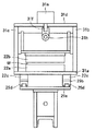
図3〜図6は、図1に示す第1実施形態の具体的な構造を示し、図3は正面図、図4は左側面図、図5は平面図、図6は右側面図である。図3〜図6に示すように、通電加熱装置20は、ワークwを上下方向から挟む電極部21a,22aと補助電極部21b,22bとにより各電極21,22が構成されている。
3 to 6 show a specific structure of the first embodiment shown in FIG. 1, FIG. 3 is a front view, FIG. 4 is a left side view, FIG. 5 is a plan view, and FIG. . As shown in FIGS. 3 to 6, in the
図3において、移動電極21が向かって左側に配置され、固定電極22が向かって右側に配置されている。移動電極21、固定電極22の何れも、対をなすリード部21c,22cと、ワークwに接触する電極部21a,22aと、ワークwを電極部21a,22a側に押圧する補助電極部21b,22bと、を備えている。
In FIG. 3, the moving
図3に示すように、移動機構25として、ガイドレール25aが左右方向に延設され、その上方に、ねじ軸からなる移動制御棒25bが左右方向に延設され、ガイドレール25a上をスライドするスライダー25cに移動制御棒25bが螺合しており、移動制御棒25bをステップモータ25dにより速度調整して回転することで、スライダー25cが左右へ移動する。
As shown in FIG. 3, as the moving
移動電極用のリード部21cが、絶縁板21dを介在してスライダー25c上に配置され、給電部1に電気的に接続された配線2aが移動電極用のリード部21cの一端部に固定され、移動用の電極部21aが移動電極用のリード部21cの他端部に固定されており、移動用の補助電極部21bを上下動可能に配置する吊り下げ機構26が配設されている。
The moving
吊り下げ機構26が、ステージ26a,壁部26b,26c及び橋部26d等で構成された架台に設けられている。即ち、ステージ26aの他端部に奥行き方向に離隔して設けられた対の壁部26b,26cと、壁部26b,26c上端に架け渡された橋部26dと、橋部26dの軸上に取り付けられたシリンダーロッド26eと、シリンダーロッド26eの先端部に取り付けられる挟持部26f(固定具と呼んでもよい。)と、補助電極部21bを絶縁して保持する保持プレート26gと、を備える。シリンダーロッド26eの先端が挟持部26fの上端に固定され、壁部26b,26cのそれぞれ対向面に支持部26iが設けられ保持プレート26gを連結軸26hで揺動可能な状態でガイドする。シリンダーロッド26eが上下動することにより、挟持部26f、連結軸26h、保持プレート26c及び補助用電極部21bが上下動する。その際、ワークwの加熱領域を横断するように固定用の電極部21a及び補助用電極部21bが延びているので、連結軸26hで揺動されることにより、固定用の電極部21aの上面と補助用電極21bの下面の各全面をワークwに押し当てることができる。
The
吊り下げ機構26及び移動電極用のリード部21cが移動機構25により左右に移動しても、移動用の電極部21aと移動用の補助電極部21bとが平板状のワークwに接触したまま挟持するように、移動用の電極部21a、移動用の補助電極部21bでは、何れも、ワークwの奥行き方向にワークwを横断するように転動ローラ27a,27bが配置され、転動ローラ27a,27bを一対の軸受28a,28bで転動自在にしている。移動機構25で移動用の電極部21a及び移動用の補助電極部26bを左右に移動しても、一対の軸受28a,28b及び転動ローラ27aを経由してワークwに通電した状態を維持することができる。
Even if the
通電加熱装置20の他方側には固定電極22が設置されている。図3に示すように、固定電極用の引っ張り手段29がステージ29a上に配置されている。固定電極用のリード部22cが固定電極用の引っ張り手段29上に絶縁板29bを介在して配置されている。給電部1に電気的に接続された配線2bが固定電極用のリード部22cの一端部に固定されている。固定用の電極部22aは固定電極用のリード部22cの他端部に固定されている。固定用の補助電極部22bを上下動可能に配置する吊り下げ機構31が固定用の電極部22aを覆うように配置される。
A fixed
固定電極用の引っ張り手段29は、絶縁板29bの下面に接続されてステージ29aを左右に移動させる移動手段29cと、絶縁板26bを直接左右にスライドするためのスライダー29d,29eと、スライダー29d,29eをガイドするガイドレール29fとを有しており、移動手段29cによって、補助電極部22b、電極部22a及び固定電極用のリード部22cを左右にスライドして位置調整する。通電加熱装置20にこのような引っ張り手段29を設けていることにより、ワークwが通電加熱により膨張しても平坦化することができる。
The pulling means 29 for the fixed electrode is connected to the lower surface of the insulating
吊り下げ機構31は、ステージ31aの他端部に奥行き方向に離隔して立設した対の壁部31b,31cと、壁部31b,31c上端に架け渡された橋部31dと、橋部31dの軸上に取り付けられたシリンダーロッド31eと、シリンダーロッド31eの先端部に取り付けられる挟持部31fと、補助電極部22bを絶縁して保持する保持プレート31gと、を備える。保持プレート31gは連結軸31hを介して挟持部31fで挟持される。シリンダーロッド31eの先端が挟持部31fの上端に固定され、吊り下げ機構26と同様に、壁部31b,31cのそれぞれ対向面に設けた支持部によって保持プレートを揺動自在に支持する。シリンダーロッド31eが上下動することにより、挟持部31f、連結軸31h、保持プレート31g及び補助用電極部22bが上下動する。その際、ワークwの加熱領域を横断するように固定用の電極部22a及び補助用電極部22bが延びているので、連結軸31hで揺動することにより、固定用の電極部22aの上面と補助用電極部22bの下面の各全面をワークwに押し当てることができる。
The suspending
図3乃至図6に示さないが、水平支持手段によってワークwを水平に支持しておき、固定用電極21と補助用電極22でワークwを挟んで固定し、移動用電極21と補助電極22とでワークwを挟み、移動機構25が移動用電極21及び補助電極22を移動する。速度調整部15bによって移動速度を制御しながら、移動機構25により移動用電極21を移動する。よって、速度調整部15bによりワークwの形状に応じて、移動用電極21及び補助電極22の移動速度を調整することによって、ワークwの加熱領域を均一に加熱したり、又はワークwの加熱領域を高温領域から低温領域に滑らかに変化するように分布させて加熱することもできる。
Although not shown in FIGS. 3 to 6, the workpiece w is supported horizontally by the horizontal support means, the workpiece w is fixed between the fixing
このように、通電加熱装置20では、ワークwを上下で挟むように電極部21aと補助用電極部21bとを配置する。ワークwの加熱領域を横断する形状を有する中実の電極部21aが、電極移動方向に沿って敷設された一対のリード部21c(ブスバーと呼んでもよい。)に横断して設けられる。電極部21aと補助用電極部21b及び一対のリード部21cが駆動機構25によって電極移動方向に沿って移動する手段に取り付けられている。電極部21a及び補助用電極部21bの少なくとも何れか一方が押圧手段としてのシリンダーロッド26eによって上下動して、電極部21aと補助用電極部21bとでワークwを挟んだまま、ワークw上を走行することにより、ブスバー21cを経由して電極部21bからワークwに通電しながら移動する。
Thus, in the
なお、図3乃至図6に示した形態のみならず、電極部21a及び補助用電極部21bの少なくとも何れか一方が押圧手段としてのシリンダーロッド26eによって上下動して、電極部21aと補助用電極部21bとでワークwを挟んだまま、電極部21aが一対のブスバー上を走行することによりブスバーを経由して電極部21bからワークwに通電しながら移動できるように設計変更してもよい。
3 to 6, at least one of the
(第2実施形態)
図7は、本発明の第2実施形態に係る通電加熱装置のコンセプトを示しており、(a)は通電前の状態の平面図、(b)は通電前の状態の正面図、(c)は通電後の状態の平面図、(d)は通電後の状態の正面図である。
(Second Embodiment)
FIG. 7: has shown the concept of the electrical heating apparatus which concerns on 2nd Embodiment of this invention, (a) is a top view of the state before electricity supply, (b) is a front view of the state before electricity supply, (c). Is a plan view of the state after energization, and (d) is a front view of the state after energization.
本発明の第2実施形態に係る通電加熱装置40は、図7に示すように、給電部1に電気的に接続され、一方の電極41及び他方の電極42からなる電極対43と、一方の電極41、他方の電極42の双方を移動する移動機構44,45と、を備える。
As shown in FIG. 7, the
各移動機構44,45は、一方の電極41,他方の電極42をワークwに接触した状態でかつ給電部1から電極対43を経由してワークwに通電している状態で、互いに接触しないように配置された一方の電極41,他方の電極42をそれぞれ移動して一方の電極41と他方の電極42との間隔を広げる。
The moving
図7に示すように、ワークwが、平面視でひし形の形状を有しており、一定の均一厚みである場合には、奥行き幅が中央部で最も長く、左右の両端部で徐々に短くなる。このようなワークwを同一の温度範囲となるように加熱するためには、一方の電極41及び他方の電極42をワークwの中央部に短い間隔を隔ててワークwを横切るように配置して給電部1から一定電流を流しながら、一方の電極41と他方の電極42とを互いに逆方向に同じ速度で移動すればよい。
As shown in FIG. 7, when the work w has a rhombus shape in plan view and has a uniform thickness, the depth width is the longest at the center and gradually shortens at both the left and right ends. Become. In order to heat such a workpiece w so as to be in the same temperature range, one
第2実施形態の具体的な装置構成については、図3〜図6に示す第1実施形態の構成のうち、左側に配置されている移動電極を右側にも配置すればよい。 About the specific apparatus structure of 2nd Embodiment, what is necessary is just to arrange | position the moving electrode arrange | positioned on the left side also on the right side among the structures of 1st Embodiment shown in FIGS.
(第3実施形態)
図8は、本発明の第3実施形態に係る通電加熱装置のコンセプトを示しており、(a)は通電前の状態の平面図、(b)は通電前の状態の正面図、(c)は通電中の状態の平面図、(d)は通電中の状態の正面図、(e)は通電後の状態の平面図、(f)は通電後の状態の正面図である。
(Third embodiment)
FIG. 8: has shown the concept of the electric heating apparatus which concerns on 3rd Embodiment of this invention, (a) is a top view of the state before electricity supply, (b) is a front view of the state before electricity supply, (c). (D) is a front view in a state of being energized, (e) is a plan view of a state after the energization, and (f) is a front view in a state after being energized.
第3実施形態では、ワークwは、図8に示すように、平面視で一方の等脚台形の領域と他方の等脚台形の領域とに対称に仮想的に区分し得るものであって、各領域のうち互いに平行な辺部の対のうち長辺部を外側に配置して短辺部同士を連続してなるものである。つまり、第1実施形態の図1において示したワークwを二つ連結したようなものである。その場合には、第1実施形態に係る通電加熱装置10を次のように改良することにより、本発明を適用することができる。
In the third embodiment, as shown in FIG. 8, the workpiece w can be virtually divided symmetrically into one isosceles trapezoidal region and the other isosceles trapezoidal region in plan view, In each region, the long side portion of the pair of side portions parallel to each other is arranged outside and the short side portions are continuously arranged. That is, it is like connecting two workpieces w shown in FIG. 1 of the first embodiment. In that case, the present invention can be applied by improving the
本発明の第3実施形態に係る通電加熱装置50は、電極対53a及び移動機構56aを備える通電ユニット50aと、電極対53b及び移動機構56bを備える通電ユニット50bとを、それぞれ左右に配置する。ワークwの平面視で左側に配置される電極対53aは一方の電極51aと他方の電極52aとからなる。
In the
左側の通電ユニット50aでは、固定電極として、一方の電極51aが平面視でワークwの左端部に配置され、移動電極として他方の電極52aが平面視で一方の電極51aの右側に僅かな間隔を開けて配置され、移動機構56aにより移動する。
In the
右側の通電ユニット50bでは、固定電極として、一方の電極51bが平面視でワークwの右端部に配置され、移動電極として他方の電極52bが平面視で一方の電極51bの左側に僅かな間隔を開けて配置され、移動機構55bにより移動する。
In the
各移動機構55a,55bは、第1実施形態、第2実施形態と同様、移動電極の移動速度を制御する調整部54a,54bと、調整部54a,54bによって移動電極を移動させる駆動機構55a,55bとを備える。調整部54a,54bは、ワークwの形状及び寸法に関するデータから移動電極の移動速度を求め、駆動機構55a,55bがその求めた移動速度により移動電極を移動させる。
Similar to the first and second embodiments, each of the moving
図8(a),(b)のように各電極が配置され、給電部1により各電極対53a,53bを経由してワークwに給電されている状態で、図8(c),(d)に示すように移動機構56a,56bにより他方の電極52a、52bをそれぞれ移動して、一方の電極51a,51bからそれぞれ遠ざける。その後、図8(e),(f)に示すように他方の電極52a,52bを何れもワークwから非接触となるように上下方向に移動する。その際、給電部1から各電極対53a,53bに通電を停止して、図示しない切替器を用いて回路を切り替え、電極51aと電極51bとの間に給電部1から通電を再開する。これにより、ワークwのうち他方の電極52aと他方の電極52bとの間の部位を通電して加熱することができる。
8C and 8D in a state where the electrodes are arranged as shown in FIGS. 8A and 8B and the work w is supplied by the power supply unit 1 via the electrode pairs 53a and 53b. ), The
第3実施形態においても、移動機構56a,56bで移動電極としての他方の電極52a,52bをワークwの形状及び寸法に基づいて移動速度を制御して移動することにより、電極対53aにより一方の電極51aと他方の電極52aとの間で通電し、電極対53bにより一方の電極51bと他方の電極52bとの間で通電することにより、ワークwの部位毎の熱量を等しくして、均一加熱することができる。
Also in the third embodiment, the moving
なお、通電ユニット50a,50bの各構成については第1実施形態と同様の構成を適用することができ、具体的な構成としては図3〜図6に示すものを挙げられる。
In addition, about each structure of
(第4実施形態)
図9は、本発明の第4実施形態に係る通電加熱装置のコンセプトを示しており、(a)は通電前の状態の平面図、(b)は通電前の状態の正面図、(c)は通電後の状態の平面図、(d)は通電後の状態の正面図である。
(Fourth embodiment)
FIG. 9 shows the concept of the electric heating device according to the fourth embodiment of the present invention, where (a) is a plan view of the state before energization, (b) is a front view of the state before energization, and (c). Is a plan view of the state after energization, and (d) is a front view of the state after energization.
図9に示す通電加熱装置10の構成は図1に示す通電加熱装置10と同じである。つまり、本発明の第4実施形態に係る通電加熱装置10は、給電部1に電気的に接続され、一方の電極11及び他方の電極12からなる電極対13と、一方の電極11、他方の電極12の何れか一方又は双方を移動する移動機構15と、を備える。移動機構15は、一方の電極11及び他方の電極12をワークwに接触した状態でかつ給電部1から電極対13を経由してワークwに通電している状態で、一方の電極11を移動して一方の電極11と他方の電極12との間隔を変化させる。
The configuration of the
第4実施形態は、第1実施形態とワークwの形状が異なっている。即ち、ワークwが平面視において左右方向に沿って奥行き幅が変化しておらず、厚みが一方向に減少している。これにより一方向に断面積が減少している。 The fourth embodiment differs from the first embodiment in the shape of the workpiece w. In other words, the depth width of the work w does not change along the left-right direction in plan view, and the thickness decreases in one direction. This reduces the cross-sectional area in one direction.
第4実施形態においても、ワークwの加熱領域は、電極対13に給電部11により、通電開始から停止するまでに移動電極(図9では一方の電極11)を移動することで、電極の移動方向に従って短冊状に仮想的に分割した領域毎の熱量を制御することができる。
Also in the fourth embodiment, the heating area of the workpiece w is moved by moving the moving electrode (one
例えば図9のように、ワークwが左方向に厚みが小さくなっている場合においても、移動速度を、上記式4から、断面積の変化率の2乗に比例した関数で規定される。
For example, as shown in FIG. 9 , even when the thickness of the workpiece w is reduced in the left direction, the moving speed is defined by a function proportional to the square of the change rate of the cross-sectional area from the
(第5実施形態)
図10は、本発明の第5実施形態に係る通電加熱装置のコンセプトを示しており、(a)は通電前の状態の平面図、(b)は通電前の状態の正面図、(c)は通電後の状態の平面図、(d)は通電後の状態の正面図である。
(Fifth embodiment)
FIG. 10: has shown the concept of the electric heating apparatus which concerns on 5th Embodiment of this invention, (a) is a top view of the state before electricity supply, (b) is a front view of the state before electricity supply, (c). Is a plan view of the state after energization, and (d) is a front view of the state after energization.
図10に示す通電加熱装置10は図1に示す通電加熱装置10と構成は同じである。ワークwにおいて加熱領域がワークwの全体ではなく、左右何れかの一方の領域である点において異なる。つまり、ワークwの全体領域が、加熱領域w1と非加熱領域w2の2つの領域に区分される点である。これは、加熱領域w1の素材と非加熱領域w2の素材とが異なっており、両者を溶接によって接続して一体化したものである。このようなワークwの使用例としては、加熱領域w1の硬度と増加させて非加熱領域w2を衝撃等によって変形し易くして衝撃を吸収する部材が挙げられる。この場合には、加熱領域w1のうち一方向と直交する方向に沿う断面積が大きい側に一方の電極11と他方の電極12とを配置して、その断面積が小さくなる方向に移動する。移動速度については、式4に基づいて設定すればよい。これにより、第5実施形態においても、ワークwの加熱領域w1は、電極対13に給電部11により通電開始から停止するまでに移動電極(図10では一方の電極11)を移動することで、電極の移動方向に従って短冊状に仮想的に分割した領域毎の熱量を制御することができる。
The
(第6実施形態)
図11は、本発明の第6実施形態に係る通電加熱装置のコンセプトを示しており、(a)は通電前の状態の平面図、(b)は通電前の状態の正面図、(c)は通電後の状態の平面図、(d)は通電後の状態の正面図である。
(Sixth embodiment)
FIG. 11: has shown the concept of the electrically heating apparatus which concerns on 6th Embodiment of this invention, (a) is a top view before the electricity supply, (b) is a front view of the state before electricity supply, (c). Is a plan view of the state after energization, and (d) is a front view of the state after energization.
図11に示す通電加熱装置40は図7に示す通電加熱装置40と構成は同じである。異なるのは、ワークwの左右一方は熱間加工温度にほぼ均一に加熱する領域w1であり、他方が焼入れ温度よりも低い温間加工温度に均一に加熱する領域w2である点である。このワークwはその全体領域が、異なる温度にそれぞれ加熱される領域w1,w2からなっている。このワークwは、第5実施形態と同様、領域w1の素材と領域w2の素材とが異なっており、両者を溶接によって接続して一体化したものである。この場合には、何れも移動電極41,42がそれぞれ移動機構44,45によって移動される。左側の領域w1は熱間加工温度に均一に加熱されるのに対して、右側の領域w2は温間加工温度に加熱され、後工程でプレスされやすくする。そのため、移動電極41,42の間に一定電流を流しながら、移動機構44が移動電極41を式4の関係を満たすように移動して領域w1を均一の熱間加工温度に加熱し、領域w2が所定の温間加熱温度に加熱されるよう移動機構45が移動電極42を移動する。その際、移動電極41,42のそれぞれの移動開始時間及び移動終了時間については各領域w1,w2の左右方向の寸法、熱間加工温度、温間加工温度に応じて適宜設定すればよい。
The
以上、複数の実施形態を説明したが、本発明は、ワークwの形状及び寸法に応じて適宜変更して実施することができる。ワークwは図示した形状に限定されず、ワークwが、一方向に沿う断面積が小さくなるなどして単位長さ当たりの抵抗が大きくなる領域を含んでいれば、その方向に電極を移動させることによりその領域を均一加熱することができる。なお、ワークwは、外周辺のうち左右端をつなぐ横辺は直線である必要はなく湾曲していてもよいし、横辺が複数の直線や曲率の異なる曲線をつなげて構成されていてもよい。
While a plurality of embodiments have been described above, the present invention can be implemented with appropriate modifications according to the shape and dimensions of the workpiece w. Workpiece w is not limited to the shape shown, the workpiece w is if it contains a region in which resistance increases per unit by, for example, the cross-sectional area along the one direction becomes smaller length, moving the electrode in that direction Thus, the region can be heated uniformly. Note that the workpiece w may be curved without being a straight line connecting the left and right ends of the outer periphery, or may be configured by connecting a plurality of straight lines or curves with different curvatures. Good.
また、上述の説明では、ワークw全体が加熱領域である場合、ワークwの一部が加熱領域である場合、ワークwが複数の領域に分けられており各領域が加熱領域である場合について説明しているが、それ以外にも、ワークwに対して間隔をおいて配置される一方及び他方の電極の何れかの移動電極の移動方向に対して交差する方向に、つまりワークwの左右方向ではなく奥行き方向に加熱領域が分かれており、その各加熱領域毎に移動電極を配置するようにしてもよい。その際、加熱領域は奥行き方向に隣接して分かれていてもよいし、奥行き方向に分離して設定されていてもよい。 In the above description, the case where the entire workpiece w is a heating region, a part of the workpiece w is a heating region, the workpiece w is divided into a plurality of regions, and each region is a heating region. However, other than that, in the direction intersecting the moving direction of one of the moving electrodes of one and the other of the electrodes arranged at an interval with respect to the work w, that is, the horizontal direction of the work w Instead, the heating area is divided in the depth direction, and a moving electrode may be arranged for each heating area. In that case, the heating region may be divided adjacent to the depth direction, or may be set separately in the depth direction.
このように、ワークwの形状及び寸法並びにワークwにおける加熱領域に応じて移動すべき電極を一又は複数設けてワークwを通電加熱するように適宜設計変更することも、本発明の範囲に含まれる。その際、固定電極を必要に応じて用いてもよい。 As described above, it is also included in the scope of the present invention to appropriately change the design so that the work w is energized and heated by providing one or a plurality of electrodes to be moved according to the shape and size of the work w and the heating region of the work w. It is. In that case, you may use a fixed electrode as needed.
1:給電部
2a,2b:配線
5L,5R:電極
10,20,40,50:通電加熱装置
11:一方の電極(移動電極)
12:他方の電極(固定電極)
13:電極対
15:移動機構
15a:調整部
15b:駆動機構
21:電極(移動電極)
22:電極(固定電極)
21a,22a:電極部
21b,22b:補助電極部
21c,22c:リード部
21d:絶縁板
25:移動機構
25a:ガイドレール
25b:移動制御棒
25c:スライダー
25d:ステップモータ
26,31:吊り下げ機構
26a,31a:ステージ
26b,26c,31b,31c:壁部
26d,31d:橋部
26e,31e:シリンダーロッド
26f,31f:挟持部
26g,31g:保持プレート
26h,31h:連結軸
26i:支持部
27a,27b:転動ローラ
28a,28b:軸受
29:引っ張り手段
29a:ステージ
29b:絶縁板
29c:移動手段
29d,29e:スライダー
29f:ガイドレール
41:一方の電極(移動電極)
42:他方の電極(移動電極)
43:電極対
44,45:移動機構
44a,45a:調整部
44b,45b:駆動機構
50a,50b:通電ユニット
51a,51b:一方の電極(固定電極)
52a,52b:他方の電極(移動電極)
53a,53b:電極対
54a,54b:駆動機構
55a,55b:調整部
56a,56b:移動機構
1:
12: The other electrode (fixed electrode)
13: Electrode pair 15: Moving
22: Electrode (fixed electrode)
21a, 22a:
42: The other electrode (moving electrode)
43:
52a, 52b: other electrode (moving electrode)
53a, 53b: Electrode pairs 54a, 54b: Drive
Claims (7)
前記一方の電極及び他方の電極をワークに接触した状態でかつ前記給電部から前記電極対を経由してワークに通電している状態で、前記一方の電極、前記他方の電極の何れか一方又は双方を移動して前記一方の電極と前記他方の電極との間隔を変化させる移動機構と、
を備え、
前記移動機構は、前記一方の電極及び前記他方の電極のうち移動すべき電極の移動速度を制御する調整部と、該調整部によって前記移動すべき電極を移動させる駆動機構とを備える、通電加熱装置。 An electrode pair that is electrically connected to the power supply unit and includes one electrode and the other electrode;
In a state where via pre Symbol electrode pairs before SL one electrode and the other electrode from a state at and before Symbol feeding portion in contact with the workpiece is energized in the work, before Symbol One electrode, prior SL other electrode a moving mechanism for changing the distance between the front SL one electrode before SL other electrode move either one or both of,
Equipped with a,
The moving mechanism, Ru includes an adjusting unit that controls the moving speed of the electrode to be moved out of the one electrode and the other electrode, and a driving mechanism for moving the electrode to be the movement by the adjustment unit, the energization Heating device.
Priority Applications (6)
| Application Number | Priority Date | Filing Date | Title |
|---|---|---|---|
| JP2011261076A JP5887884B2 (en) | 2011-11-29 | 2011-11-29 | Electric heating device |
| US14/361,641 US20140339210A1 (en) | 2011-11-29 | 2012-11-29 | Direct resistance heating apparatus and direct resistance heating method |
| CN201280058566.9A CN104025703B (en) | 2011-11-29 | 2012-11-29 | Direct resistance heating equipment and direct resistance heating method |
| EP12809868.8A EP2786636B1 (en) | 2011-11-29 | 2012-11-29 | Direct resistance heating apparatus and direct resistance heating method |
| PCT/JP2012/081588 WO2013081180A1 (en) | 2011-11-29 | 2012-11-29 | Direct resistance heating apparatus and direct resistance heating method |
| ES12809868.8T ES2578157T3 (en) | 2011-11-29 | 2012-11-29 | Direct resistance heating apparatus and a direct resistance heating method |
Applications Claiming Priority (1)
| Application Number | Priority Date | Filing Date | Title |
|---|---|---|---|
| JP2011261076A JP5887884B2 (en) | 2011-11-29 | 2011-11-29 | Electric heating device |
Publications (3)
| Publication Number | Publication Date |
|---|---|
| JP2013114941A JP2013114941A (en) | 2013-06-10 |
| JP2013114941A5 JP2013114941A5 (en) | 2015-01-22 |
| JP5887884B2 true JP5887884B2 (en) | 2016-03-16 |
Family
ID=48710290
Family Applications (1)
| Application Number | Title | Priority Date | Filing Date |
|---|---|---|---|
| JP2011261076A Active JP5887884B2 (en) | 2011-11-29 | 2011-11-29 | Electric heating device |
Country Status (1)
| Country | Link |
|---|---|
| JP (1) | JP5887884B2 (en) |
Families Citing this family (5)
| Publication number | Priority date | Publication date | Assignee | Title |
|---|---|---|---|---|
| JP6024063B2 (en) * | 2012-07-07 | 2016-11-09 | 高周波熱錬株式会社 | Electric heating method |
| JP6463911B2 (en) * | 2014-06-24 | 2019-02-06 | 高周波熱錬株式会社 | Heating method, heating apparatus, and method for producing press-molded product |
| JP6450608B2 (en) * | 2015-03-05 | 2019-01-09 | 高周波熱錬株式会社 | Heating method, heating apparatus, and method for producing press-molded product |
| JP6384417B2 (en) * | 2015-07-17 | 2018-09-05 | トヨタ自動車株式会社 | Electric heating device and electric heating method |
| JP6957279B2 (en) * | 2017-09-11 | 2021-11-02 | 高周波熱錬株式会社 | Energizing heating device and energizing heating method, heating device and heating method, and hot press molding method |
Family Cites Families (10)
| Publication number | Priority date | Publication date | Assignee | Title |
|---|---|---|---|---|
| JPS5118313U (en) * | 1974-07-26 | 1976-02-10 | ||
| JPS537517A (en) * | 1977-07-11 | 1978-01-24 | Shiroyama Seisakusho Kk | Process and apparatus for resistance heating of steel bar etc by passing of electricity |
| US4473738A (en) * | 1981-10-05 | 1984-09-25 | Dayton Superior Corporation | Method and apparatus for hot forming a polygonal head on a snap tie rod |
| JPS6137922A (en) * | 1984-07-27 | 1986-02-22 | Aichi Steel Works Ltd | Continuous electrical heating method |
| JPH02111817A (en) * | 1988-10-21 | 1990-04-24 | Daido Steel Co Ltd | Electric power conductive heating method |
| US5515705A (en) * | 1992-01-23 | 1996-05-14 | Board Of Regents, The University Of Texas System | Apparatus and method for deforming a workpiece |
| JP3587501B2 (en) * | 1998-05-26 | 2004-11-10 | 高周波熱錬株式会社 | Heating method and heating device for deformed parts |
| JP2000271779A (en) * | 1999-03-26 | 2000-10-03 | Kanai Hiroaki | Method and device for annealing metal wire immediately after welding |
| JP3814690B2 (en) * | 2002-03-29 | 2006-08-30 | 財団法人生産技術研究奨励会 | Electric heating device and electric heating method |
| JP5072234B2 (en) * | 2006-02-21 | 2012-11-14 | 株式会社ミヤデン | Rack bar induction hardening equipment |
-
2011
- 2011-11-29 JP JP2011261076A patent/JP5887884B2/en active Active
Also Published As
| Publication number | Publication date |
|---|---|
| JP2013114941A (en) | 2013-06-10 |
Similar Documents
| Publication | Publication Date | Title |
|---|---|---|
| JP5887885B2 (en) | Electric heating method | |
| JP6142409B2 (en) | Electric heating method | |
| JP6024063B2 (en) | Electric heating method | |
| EP2786636B1 (en) | Direct resistance heating apparatus and direct resistance heating method | |
| JP5887884B2 (en) | Electric heating device | |
| CN104334751A (en) | Current applying apparatus, current applying method and direct resistance heating apparatus | |
| US10638544B2 (en) | Heating method, heating apparatus and method of manufacturing press-molded article | |
| EP3682037B1 (en) | Direct resistance heating apparatus, direct resistance heating method, heating apparatus, heating method, and hot-press molding method | |
| JP2016162727A (en) | Heating method and heating device and method of manufacturing press molding | |
| WO2016017147A1 (en) | Direct resistance heating method and press-molded product manufacturing method |
Legal Events
| Date | Code | Title | Description |
|---|---|---|---|
| A521 | Request for written amendment filed |
Free format text: JAPANESE INTERMEDIATE CODE: A523 Effective date: 20141128 |
|
| A621 | Written request for application examination |
Free format text: JAPANESE INTERMEDIATE CODE: A621 Effective date: 20141128 |
|
| A131 | Notification of reasons for refusal |
Free format text: JAPANESE INTERMEDIATE CODE: A131 Effective date: 20150929 |
|
| A521 | Request for written amendment filed |
Free format text: JAPANESE INTERMEDIATE CODE: A523 Effective date: 20151130 |
|
| TRDD | Decision of grant or rejection written | ||
| A01 | Written decision to grant a patent or to grant a registration (utility model) |
Free format text: JAPANESE INTERMEDIATE CODE: A01 Effective date: 20160112 |
|
| A61 | First payment of annual fees (during grant procedure) |
Free format text: JAPANESE INTERMEDIATE CODE: A61 Effective date: 20160201 |
|
| R150 | Certificate of patent or registration of utility model |
Ref document number: 5887884 Country of ref document: JP Free format text: JAPANESE INTERMEDIATE CODE: R150 |
|
| R250 | Receipt of annual fees |
Free format text: JAPANESE INTERMEDIATE CODE: R250 |
|
| R250 | Receipt of annual fees |
Free format text: JAPANESE INTERMEDIATE CODE: R250 |
|
| R250 | Receipt of annual fees |
Free format text: JAPANESE INTERMEDIATE CODE: R250 |
|
| R250 | Receipt of annual fees |
Free format text: JAPANESE INTERMEDIATE CODE: R250 |
|
| R250 | Receipt of annual fees |
Free format text: JAPANESE INTERMEDIATE CODE: R250 |
|
| R250 | Receipt of annual fees |
Free format text: JAPANESE INTERMEDIATE CODE: R250 |