JP5884233B2 - Article insertion unit - Google Patents
Article insertion unit Download PDFInfo
- Publication number
- JP5884233B2 JP5884233B2 JP2011100553A JP2011100553A JP5884233B2 JP 5884233 B2 JP5884233 B2 JP 5884233B2 JP 2011100553 A JP2011100553 A JP 2011100553A JP 2011100553 A JP2011100553 A JP 2011100553A JP 5884233 B2 JP5884233 B2 JP 5884233B2
- Authority
- JP
- Japan
- Prior art keywords
- article
- film
- packaging material
- shrink film
- mount
- Prior art date
- Legal status (The legal status is an assumption and is not a legal conclusion. Google has not performed a legal analysis and makes no representation as to the accuracy of the status listed.)
- Expired - Fee Related
Links
- 238000003780 insertion Methods 0.000 title claims description 54
- 230000037431 insertion Effects 0.000 title claims description 54
- 239000005022 packaging material Substances 0.000 claims description 71
- 238000013459 approach Methods 0.000 claims description 8
- 230000037237 body shape Effects 0.000 claims description 2
- 229920006300 shrink film Polymers 0.000 description 82
- 238000004806 packaging method and process Methods 0.000 description 24
- 238000004519 manufacturing process Methods 0.000 description 22
- 210000000078 claw Anatomy 0.000 description 10
- 229920006302 stretch film Polymers 0.000 description 5
- 238000010438 heat treatment Methods 0.000 description 4
- 239000002985 plastic film Substances 0.000 description 4
- 238000000034 method Methods 0.000 description 3
- 230000003028 elevating effect Effects 0.000 description 2
- 238000001125 extrusion Methods 0.000 description 2
- 239000000463 material Substances 0.000 description 2
- 239000000123 paper Substances 0.000 description 2
- 230000002093 peripheral effect Effects 0.000 description 2
- 230000000694 effects Effects 0.000 description 1
- 230000001360 synchronised effect Effects 0.000 description 1
- 229920003002 synthetic resin Polymers 0.000 description 1
- 239000000057 synthetic resin Substances 0.000 description 1
- 238000007666 vacuum forming Methods 0.000 description 1
Images


Description
この発明は、台紙に固着された筒状のフィルムに物品を挿入するための物品挿入ユニットに関する。 The present invention relates to an article insertion unit for inserting an article into a cylindrical film fixed to a mount.
箱詰め包装等に比べて製造コストが安く、購入者は商品を見て選べる等の利点があるため、プラスチックシートを真空成形することによって物品収容凹部を形成し、この物品収容凹部に物品を収容した状態で、プラスチックシートにおける物品収容凹部の外側部分を厚紙等からなる台紙に固着してなる、所謂、ブリスターパックと呼ばれる包装形態が従来から採用されているが、近年では、さらにコストダウンを図るために、筒状のシュリンクフィルム等によってオーバーラップ包装を施した物品が台紙に接着固定された新たな包装形態が採用されるようになってきている。 The manufacturing cost is lower than that of boxed packaging, and the purchaser has the advantage of being able to select and see the product. Therefore, an article-receiving recess is formed by vacuum forming a plastic sheet, and the article is stored in the article-receiving recess. In this state, a so-called blister pack packaging form in which the outer portion of the article housing recess in the plastic sheet is fixed to a backing made of cardboard or the like has been conventionally employed. In addition, a new packaging form in which an article that has been overlap-wrapped with a cylindrical shrink film or the like is bonded and fixed to a mount has been adopted.
こういった台紙付きフィルム包装体を製造するには、例えば、筒状のシュリンクフィルムを台紙に固着してなる台紙付きフィルムを予め製造しておき、この台紙付きフィルムにおける筒状のシュリンクフィルムに物品を手作業で挿入した後、シュリンクフィルムを加熱収縮させることによってシュリンクフィルムを物品に密着させることになるが、物品を手作業で筒状のシュリンクフィルムに挿入していたのでは、生産性が悪く、製造コストが高くなるといった問題がある。 In order to manufacture such a film package with a mount, for example, a film with a mount formed by fixing a cylindrical shrink film to the mount is manufactured in advance, and an article is attached to the cylindrical shrink film in the film with the mount. After manually inserting the shrink film, the shrink film is heated and shrunk to bring the shrink film into close contact with the article. However, if the article is manually inserted into the cylindrical shrink film, the productivity is poor. There is a problem that the manufacturing cost becomes high.
そこで、この発明の課題は、台紙付きフィルム包装体の製造を自動化すべく、台紙付きフィルムに物品を自動挿入することができる物品挿入ユニットを提供することにある。 Therefore, an object of the present invention is to provide an article insertion unit that can automatically insert an article into a film with a mount in order to automate the production of a film package with a mount.
上記の課題を解決するため、請求項1に係る発明は、台紙に筒状フィルムが固着された包材における筒状フィルムに、扁平な一端側から略円形の他端側に向かって、胴部形状が変化していくチューブタイプの物品を挿入するための物品挿入ユニットであって、筒状フィルムを予備的に開口する予備開口手段と、前記予備開口手段によって予備的に開口した筒状フィルムの開口端を物品の挿入端部である扁平な一端側より大きく拡開する拡開手段と、前記拡開手段によって開口端が拡開された筒状フィルムに物品を扁平な一端側から押し込む物品押込手段とを備えており、前記拡開手段は、相対的に開閉可能な複数のガイド体を有し、予備開口された筒状フィルムの開口端に、閉じた状態の前記ガイド体を挿入し、そのガイド体を開くことによって筒状フィルムを拡開するようになっており、前記ガイド体は、左右方向に接近離反可能で、相互に離反する方向に付勢された左右一対の可動ガイドを有し、左右一対の可動ガイドを挿入した状態で相互に離反させることで左右方向に拡開された筒状フィルムに、前記物品押込手段によって物品を扁平な一端側から押し込んでいく際、物品の挿入量が大きくなるに従って、上下方向に離反しながら左右方向に接近していくことで円形状に近づいていく筒状フィルムに押されて左右一対の可動ガイドが相互に接近するように構成されていることを特徴とする物品挿入ユニットを提供するものである。
なお、ここにいう「台紙」は、厚紙等の紙製のものに限定されるものではなく、プラスチックシート等からなる合成樹脂製のものも含まれる。
また、物品を寝かせた状態で載置する載置台と、包材を、その筒状フィルムの開口端が前記載置台に載置された物品の挿入端部と対向するように、その台紙部分を保持する保持手段とをさらに設ける構成を採用することもできる。
In order to solve the above-described problems, the invention according to claim 1 is directed to a tubular film in a packaging material in which a tubular film is fixed to a mount, from a flat one end to a substantially circular other end. An article insertion unit for inserting a tube-type article whose shape changes , comprising: a preliminary opening means for preliminarily opening a cylindrical film; and a cylindrical film preliminarily opened by the preliminary opening means. Widening means for widening the open end from the flat one end side that is the insertion end of the article, and article pushing for pushing the article from the flat one end side into the cylindrical film whose open end is widened by the widening means The expansion means has a plurality of guide bodies that can be opened and closed relatively, and inserts the closed guide body into the open end of the preliminarily opened tubular film, By opening the guide body Adapted to expanding the tubular film Te, the guide body, the left-right direction can be toward and away from, have a biased pair of movable guide in a direction away from each other, a pair of right and left movable When the article is pushed from the flat one end side by the article pushing means into the tubular film expanded in the left-right direction by being separated from each other with the guide inserted, the insertion amount of the article increases, An article characterized in that a pair of left and right movable guides approach each other by being pushed by a cylindrical film approaching a circular shape by approaching in the left-right direction while separating in the vertical direction An insertion unit is provided.
The “mounting paper” here is not limited to paper made of cardboard or the like, but also includes a synthetic resin made of a plastic sheet or the like.
In addition, the mounting portion for placing the article in a laid state, and the packaging material, the mounting portion of the cylindrical film so that the opening end of the tubular film faces the insertion end portion of the article placed on the placement table. It is also possible to employ a configuration in which holding means for holding is further provided.
以上のように、請求項1に係る発明の物品挿入ユニットでは、拡開手段が、左右方向に接近離反可能で、相互に離反する方向に付勢された左右一対の可動ガイドを有し、左右一対の可動ガイドを挿入した状態で相互に離反させることで左右方向に拡開された筒状フィルムに、前記物品押込手段によって物品を扁平な一端側から押し込んでいく際、物品の挿入量が大きくなるに従って、上下方向に離反しながら左右方向に接近していくことで円形状に近づいていく筒状フィルムに押されて左右一対の可動ガイドが相互に接近するように構成されているので、扁平な一端側から略円形の他端側に向かって、胴部形状が変化していくチューブタイプの物品を、筒状フィルムに円滑に挿入することができる。 As described above, in the article insertion unit according to the first aspect of the present invention, the spreading means has a pair of left and right movable guides that can approach and separate in the left-right direction and are biased in directions away from each other. When the article is pushed from the flat one end side by the article pushing means into the cylindrical film expanded in the left-right direction by separating the pair of movable guides from each other, the insertion amount of the article is large. with increasing, since the vertical direction away and pushed into the tubular film that approaches the circular shape by going close to the left-right direction while left and right pair of movable guides are configured to approach each other, flat A tube-type article whose body shape changes from one end side toward the other end side of a substantially circular shape can be smoothly inserted into the cylindrical film.
以下、実施の形態について図面を参照して説明する。図1は、図16(a)、(b)及び図17(a)、(b)に示すように、厚紙やプラスチックシート等からなる台紙Mにシート状に折り畳まれた状態の筒状シュリンクフィルムFが固着された包材MFにおける筒状シュリンクフィルムF内にボトルタイプの物品Gを挿入し、台紙Mの一端と物品Gの一端(底面)とが一致するように位置決めした状態で筒状シュリンクフィルムFを加熱収縮させた、自立性を有する台紙付きフィルム包装体PGを製造するための製造装置1を示しており、この製造装置1には、本発明に係る物品挿入ユニットの一実施形態である開口・挿入ユニットが搭載されている。なお、包材MFにおける筒状シュリンクフィルムF内に物品Gを挿入したものを、以下、中間包装体RPという。 Hereinafter, embodiments will be described with reference to the drawings. FIG. 1 shows a cylindrical shrink film in a state of being folded into a sheet on a mount M made of cardboard, plastic sheet or the like, as shown in FIGS. 16 (a), 16 (b) and 17 (a), 17 (b). The tubular shrink film F is inserted in the tubular shrink film F in the packaging material MF to which F is fixed, and is positioned so that one end of the mount M and one end (bottom surface) of the article G coincide with each other. 1 shows a manufacturing apparatus 1 for manufacturing a self-supporting film package PG with a backing, in which F is heated and shrunk, and this manufacturing apparatus 1 is an embodiment of an article insertion unit according to the present invention. An opening / insertion unit is installed. In addition, what inserted the articles | goods G in the cylindrical shrink film F in the packaging material MF is hereafter called intermediate packaging body RP.
この台紙付きフィルム包装体PGの製造装置1は、同図に示すように、包材MFを包材供給位置αに順次供給する包材供給ユニット10と、包装しようとする物品Gを、物品受渡位置βを介して、物品供給位置γに順次供給する物品供給ユニット20と、前記包材供給ユニット10によって包材供給位置αに供給された包材MFを物品挿入位置δに順次搬送する包材・中間包装体搬送ユニット30と、この包材・中間包装体搬送ユニット30によって物品挿入位置δに搬送されてきた包材MFにおける筒状シュリンクフィルムFを開口し、物品供給ユニット20によって物品供給位置γに供給される物品Gを、開口された筒状シュリンクフィルムF内に挿入することで中間包装体RPを形成する開口・挿入ユニット40と、この開口・挿入ユニット40によって、包材MFにおける筒状シュリンクフィルムF内に物品Gが挿入された中間包装体RPを搬出する中間包装体搬出ユニット50とを備えており、前記包材・中間包装体搬送ユニット30は、物品挿入位置δにおいて、包材MFにおける筒状シュリンクフィルムF内に物品Gが挿入された中間包装体RPを中間包装体搬出位置εまで搬送するようになっている。なお、前記中間包装体搬出ユニット50によって搬出される中間包装体RPは、図示しない加熱ユニットによって加熱され、筒状シュリンクフィルムFが熱収縮することにより、筒状シュリンクフィルムFが物品Gに密着した台紙付きフィルム包装体PGが製造される。
As shown in the figure, the manufacturing apparatus 1 for a film packaging body PG with a mount mounts a packaging
前記包材供給ユニット10は、図2〜図4に示すように、多数の包材MFを集積するストッカ11と、このストッカ11に集積された多数の包材MFから最下位の包材MFを取り出す、ストッカ11の下方側で昇降する吸引パッド12aを有する包材取出手段12と、この包材取出手段12によって、ストッカ11から取り出された包材MFを載置する包材載置台13と、この包材載置台13に載置された包材MFを包材供給位置αに押し出すプッシャ14とを備えている。
As shown in FIGS. 2 to 4, the packaging
前記ストッカ11は、その下端開口部に包材MFにおける幅方向の両側縁をそれぞれ係止する係止爪11aを有しており、この係止爪11aに係止されている最下位の包材MFの下面を吸引パッド12aによって吸引保持した状態で、その吸引パッド12aが降下することにより、最下位の包材MFが係止爪11aから外れてストッカ11から取り出されるようになっている。
The
前記物品供給ユニット20は、図1に示すように、物品を物品受渡位置βに順次搬送するバケットコンベア21と、バケットコンベア21によって物品受渡位置βに供給された物品を物品供給位置γに順次押し出すプッシャ22とを備えている。
As shown in FIG. 1, the
前記包材・中間包装体搬送ユニット30は、図1、図3(b)及び図4に示すように、同心円上に設定された包材供給位置α、物品挿入位置δ及び中間包装体搬出位置εを含む略円盤状の回転テーブル31と、包材供給位置α、物品挿入位置δ及び中間包装体搬出位置εに対応するように、90度の割出角度で回転テーブル31上に設けられた、包材MFが嵌り込んで位置決めされる位置決めガイド32と、位置決めガイド32によって位置決めされた包材MFにおける台紙Mを下方側から吸引保持する吸引パッド34とを備えており、回転テーブル31は、図示しない駆動手段によって、90度の回転角度で間欠的に回転駆動するようになっている。
The packaging material / intermediate
前記位置決めガイド32は、回転テーブル31の周縁側が開放されており、回転テーブル31の外側から、包材供給位置αに位置している位置決めガイド32内に包材MFを供給したり、中間包装体搬出位置εに位置している位置決めガイド32内に嵌り込んでいる中間包装体RPを回転テーブル31の外側に排出したりすることができるようになっている。
The
また、位置決めガイド32には、回転テーブル31の回転中心側の辺部内縁に後述する中間包装体搬出ユニット50の掛止爪54が侵入可能な切欠部32aが形成されており、中間包装体RPを位置決めした状態で、掛止爪54を中間包装体RPにおける台紙Mの端縁に掛止することができるようになっている。
Further, the
また、回転テーブル31の外周縁には、図1に示すように、各ガイドフレーム32の開放端を開閉する開閉機構33が設けられており、中間包装体RPを物品挿入位置δから中間包装体搬出位置εまで搬送する間に、回転テーブル31の回転に伴う遠心力によって、包材MFの筒状シュリンクフィルムFから物品Gが飛び出さないように、各位置決めガイド32が物品挿入位置δから中間包装体搬出位置εまで移動する間は、その位置決めガイド32に対応する開閉機構33がその位置決めガイド32の開放端を閉塞するようになっている。
As shown in FIG. 1, an opening /
前記開口・挿入ユニット40は、図5〜図7(a)、(b)に示すように、物品供給位置γに設置された、物品Gを寝かせた状態で載置する物品載置台41と、位置決めガイド32によって物品挿入位置δに位置決めされた包材MFを吸引保持する吸引パッド34と、物品挿入位置δに位置決めされた状態で、吸引パッド34によって吸引保持されている包材MFの筒状シュリンクフィルムFを予備的に開口する予備開口手段42と、この予備開口手段42によって予備的に開口した筒状シュリンクフィルムFの開口端を物品Gの挿入端部(頭部)より大きく拡開する拡開手段43と、この拡開手段43によって開口端が拡開された筒状シュリンクフィルムFに物品Gを押し込むプッシャ49とを備えており、物品載置台41は、物品挿入位置δ側に対して進退可能に支持され、駆動シリンダによって進退駆動されるようになっている。なお、物品載置台41は、必ずしも、駆動シリンダによって進退駆動させる必要はなく、例えば、カム機構や他の駆動手段によって進退させることも可能である。
As shown in FIGS. 5 to 7A and 7B, the opening /
前記予備開口手段42は、物品挿入位置δにおいて、位置決めガイド32によって位置決めされた包材MFの台紙Mを吸引保持する、上述した包材・中間包装体搬送ユニット30の構成要素である吸引パッド34と、包材MFの上方側で昇降する、包材MFにおける筒状シュリンクフィルムFの上面を吸引保持する上側吸引パッド42aとから構成されており、図8(a)〜(c)に示すように、折り畳まれた状態で台紙Mに固着されている筒状シュリンクフィルムFをこの上側吸引パッド42aによって台紙Mとの間に挟み込んで筒状シュリンクフィルムFを吸引保持した後、上側吸引パッド42aを上昇させることで、図9(a)に示すように、筒状シュリンクフィルムFを予備的に開口するようになっている。
The preliminary opening means 42 is a
前記拡開手段43は、物品載置台41の前端面に固定設置された、回転テーブル31側に張り出す下側固定ガイド44aと、物品載置台41の前端部に回動可能に支持された左右一対の回動アーム45の先端に、回転テーブル31側に張り出すように、それぞれ取り付けられた左右一対の上側可動ガイド44bと、回動アーム45と一体的に動くように、回動アーム45が固定されている回転軸に固定された左右一対の開閉操作レバー46と、この開閉操作レバー46の先端に取り付けられたカムフォロア47a及びこのカムフォロア47aに当接するカム面を有し、相互に接近離反する左右一対の操作部材47bからなるカム機構と、左右一対の開閉操作レバー46の先端部をそれぞれ外側に付勢するコイルばね48とを備えており、図8(d)〜(g)に示すように、左右一対の上側可動ガイド44aを閉じた状態で、物品載置台41を前進させることにより、図9(b)に示すように、下側固定ガイド44a及び上側可動ガイド44bが予備開口された筒状シュリンクフィルムFに挿入され、左右一対の操作部材47bを接近させることによって左右一対の開閉操作レバー46を回動させると、同図(c)に示すように、左右一対の上側可動ガイド44bが開いて、筒状シュリンクフィルムFの開口端を物品Gの挿入端よりも大きく拡開させるようになっている。
The expanding means 43 is fixedly installed on the front end surface of the article mounting table 41, and has a lower fixed
前記プッシャ49は、物品供給ユニット20のプッシャ22と同期が取られており、図8(h)に示すように、拡開手段43によって、筒状シュリンクフィルムFの開口端を物品Gの挿入端部(頭部)より大きく拡開した状態で、プッシャ49が物品Gを押し込むと、図9(c)に示すように、物品Gが下側固定ガイド44a及び上側可動ガイド44bの内側を通って筒状シュリンクフィルムFに挿入されると同時に、バケットコンベア21によって物品受渡位置βに供給された物品Gがプッシャ22によって物品供給位置γに押し出されるようになっている。
The
物品Gが筒状シュリンクフィルムFに完全に挿入されると、図8(i)に示すように、物品載置台41が初期位置に後退することで、下側固定ガイド44a及び上側可動ガイド44bが筒状シュリンクフィルムFから引き抜かれ、同図(j)に示すように、開閉機構33が位置決めガイド32の開放端を閉塞すると共に、上側可動ガイド44bが閉じることによって、初期状態に戻るようになっている。
When the article G is completely inserted into the cylindrical shrink film F, as shown in FIG. 8 (i), the article mounting table 41 moves back to the initial position, so that the lower fixed
前記中間包装体搬出ユニット50は、図10に示すように、中間包装体RPの排出方向に延びるスライドレール51と、このスライドレール51に沿って進退するスライドガイド52と、このスライドガイド52に固定設置された昇降シリンダ53と、この昇降シリンダ53のピストンロッドに固定された掛止爪54と、スライドガイド52に固定設置された、下端部が中間包装体RPの物品Gの一端側(頭部)に当接する固定アーム55と、スライドガイド52に固定設置された進退シリンダ56と、中間部がスライドガイド52に回転可能に支持されると共に進退シリンダ56のピストンロッドに一端部が回動可能に連結されたリンク58の他端部に固定されることで、進退シリンダ56のピストンロッドの出退に伴い回動し、進退シリンダ56のピストンロッドが突き出したときに先端部が物品Gの他端側(底部)に当接して固定アーム55との間に物品Gを挟み込むことで台紙Mに対する物品Gの位置決めを行う回動アーム57と、中間包装体RPの排出方向に延びるベルトコンベア59とを備えており、台紙Mに対して物品Gを位置決めした状態では、物品Gの他端(底面)と台紙Mの一方の端縁とが一致するようになっている。
As shown in FIG. 10, the intermediate
従って、中間包装体RPが位置決めガイド32によって位置決めされた状態で中間包装体搬出位置εに搬送されてくると、まず、掛止爪54が降下して位置決めガイド32に形成された切欠部32aに侵入した後、スライドガイド52が前進し始め、掛止爪54が中間包装体RPの台紙Mの端縁に掛止されると共に、固定アーム55の下端部が中間包装体RPの物品Gの一端側(頭部)に当接し、回動アーム57が下方側に回動して固定アーム55との間に物品Gを挟み込むことで台紙Mに対して物品Gを位置決めした状態で、中間包装体RPがベルトコンベア59のベルト上に押し出され、最後に回動アーム57が斜め上方側に回動して物品Gの他端側(底部)から離反するので、台紙Mに対して物品Gが位置決めされた状態で、中間包装体RPがベルトコンベア59によって排出され、図示しない加熱ユニットに送られる。なお、加熱ユニットに送られた中間包装体RPは、加熱されることによって、筒状シュリンクフィルムFが熱収縮し、筒状シュリンクフィルムFが物品Gに密着した台紙付きフィルム包装体PGが出来上がる。
Accordingly, when the intermediate package RP is positioned by the
このように、この中間包装体搬出ユニット50は、中間包装体RPを加熱ユニットに送る際、物品Gの他端(底面)と台紙Mの一方の端縁とが一致するように、台紙Mに対して物品Gを位置決めするようになっているので、出来上がった台紙付きフィルム包装体PGは全て適正な自立性を有しており、自立性の悪い台紙付きフィルム包装体PGが製造されることがない。
In this way, when the intermediate package body carrying-out
以上のように、上述した開口・挿入ユニット40は、吸引パッド34が、筒状シュリンクフィルムFの開口端が物品載置台41に載置された物品Gの挿入端部と対向するように、包材MFの台紙M部分を吸引保持した状態で、予備開口手段42が筒状シュリンクフィルムFを予備的に開口した後、拡開手段43を構成している下側固定ガイド44a及び閉じた状態の上側可動ガイド44bを筒状シュリンクフィルムFの開口端に挿入し、上側可動ガイド44bを開くことによって筒状シュリンクフィルムFを拡開した状態で、プッシャ49が物品Gを筒状シュリンクフィルムF内に押し込むことで、包材MFの筒状シュリンクフィルムFに物品Gを自動挿入することができるので、この開口・挿入ユニット40を搭載した製造装置1によって、台紙付きフィルム包装体PGの製造を自動化することが可能となり、従来のように、筒状シュリンクフィルムが台紙に固着された包材の筒状シュリンクフィルムに物品を手作業で挿入する場合に比べて、台紙付きフィルム包装体を効率よく、低コストで製造することができる。
As described above, the opening /
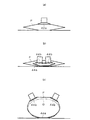
図11(a)〜(c)は、チューブタイプの物品Gを、その扁平な胴部先端側から包材MFの筒状シュリンクフィルムFに挿入するための開口・挿入ユニットに搭載された拡開手段60を示している。この拡開手段60は、同図に示すように、物品載置台41の前端面に固定設置された、回転テーブル31側に張り出す固定ガイド61と、左右方向に接近離反可能に物品載置台41の前端部に支持された左右一対のアーム63にそれぞれ取り付けられた、固定ガイド61の上側に近接した状態で回転テーブル31側に張り出す細長い左右一対の可動ガイド62と、先端側が上を向くように、物品載置台41の前端部に回動可能に支持された、先端部にカムフォロア65がそれぞれ取り付けられた左右一対の上側操作レバー64と、先端側が下を向くように、物品載置台41の前端部に回動可能に支持された、先端部にカムフォロア67がそれぞれ取り付けられた左右一対の下側操作レバー66と、左右一対のアーム63にそれぞれ取り付けられた、上側操作レバー64のカムフォロア65が当接するカム面を有するブロック68と、左右一対の可動ガイド62が相互に離反する方向に左右一対のアーム63を付勢するコイルばね69と、下側操作レバー66の先端に取り付けられたカムフォロア67及びこのカムフォロア67に当接するカム面を有し、相互に接近離反する左右一対の操作部材70からなるカム機構と、左右一対の下側操作レバー66の先端部をそれぞれ外側に付勢するコイルばね71とを備えており、上側操作レバー64と下側操作レバー66とは、同一回転軸に固定されることで、一体的に回動するようになっている。
11 (a) to 11 (c) show an expansion mounted on an opening / insertion unit for inserting a tube-type article G into the cylindrical shrink film F of the packaging material MF from its flat front end side. Means 60 are shown. As shown in the figure, the expanding means 60 is fixedly installed on the front end surface of the article mounting table 41 and is fixed to the rotary table 31 side, and the article mounting table 41 is capable of approaching and separating in the left-right direction. The pair of left and right
以下、チューブタイプの物品Gの筒状シュリンクフィルムFへの挿入動作について説明する。まず、図12(a)に示すように、予備開口手段42(上側吸引パッド42a)が筒状シュリンクフィルムFを予備的に開口した後、図11(a)に示すように、左右一対の操作部材70を最も離反させることによって、左右一対の可動ガイド62を閉じた状態で、図12(b)に示すように、固定ガイド61及び可動ガイド62が予備開口された筒状シュリンクフィルムFに挿入される。
Hereinafter, an insertion operation of the tube-type article G into the cylindrical shrink film F will be described. First, as shown in FIG. 12A, after the preliminary opening means 42 (
続いて、図11(b)に示すように、左右一対の操作部材70を相互に接近させることによって、左右一対の下側操作レバー66の先端部を相互に接近させると、これに伴って、左右一対の上側操作レバー64の先端部が相互に離反するので、コイルばね69の付勢力によって可動ガイド62も離反し、図12(c)に示すように、この可動ガイド62によって筒状シュリンクフィルムFの開口端が左右方向に広げられ、この状態で、物品Gが、その扁平な胴部先端側から筒状シュリンクフィルムF内に挿入される。
Subsequently, as shown in FIG. 11 (b), by bringing the pair of left and
チューブタイプの物品Gの場合、扁平な先端側から略円形のキャップ側に向かって、胴部形状が変化していくので、物品Gの扁平な胴部先端が筒状シュリンクフィルムF内に挿入された後は、その挿入量が大きくなるに従って、筒状シュリンクフィルムFの断面形状が円形状に近づいていき、図11(c)及び図12(d)に示すように、左右一対の可動ガイド62が筒状シュリンクフィルムFに押されて相互に接近しながら、物品Gが挿入されることになる。
In the case of the tube-type article G, the barrel shape changes from the flat tip side toward the substantially circular cap side, so that the flat barrel tip of the article G is inserted into the cylindrical shrink film F. After that, as the amount of insertion increases, the cross-sectional shape of the cylindrical shrink film F approaches a circular shape, and a pair of left and right
以上のように、こういった拡開手段60を搭載した開口・挿入ユニットでは、左右一対の可動ガイド62が、筒状シュリンクフィルムFの開口端を通過する物品Gの断面形状に応じて、開閉するようになっているので、包装しようとしている物品Gが、全長に渡って断面形状が大きく変化するチューブ容器等のようなものであっても、物品Gにおける筒状シュリンクフィルムFの開口端を通過する部分の形状に合わせて筒状シュリンクフィルムFの開口端を拡開することができ、物品Gを筒状シュリンクフィルムFに円滑に挿入することができる。
As described above, in the opening / insertion unit equipped with such a spreading
なお、上述した各実施形態では、物品Gの筒状シュリンクフィルムFへの挿入開始から挿入完了までの間、下側固定ガイド44a及び上側可動ガイド44bや固定ガイド61及び可動ガイド62を、常時、筒状シュリンクフィルムF内に挿入しているが、これに限定されるものではなく、物品Gの挿入端部を筒状シュリンクフィルムFに挿入した後は、側固定ガイド44a及び上側可動ガイド44bや固定ガイド61及び可動ガイド62を筒状シュリンクフィルムFの外側に待避させるようにしてもよい。このように、物品Gの挿入端部が筒状シュリンクフィルムFに挿入された後、側固定ガイド44a及び上側可動ガイド44bや固定ガイド61及び可動ガイド62を筒状シュリンクフィルムFから待避させるようにしておくと、全長に渡って断面形状が大きく変化するチューブ容器等のようなものであっても、筒状シュリンクフィルムF自体が物品Gに沿うように変形しながら、物品Gが筒状シュリンクフィルムF内に挿入されていくことになり、物品Gを筒状シュリンクフィルムFに円滑に挿入することができる。
In each of the above-described embodiments, the lower fixed
また、上述した各実施形態では、台紙Mに対して筒状シュリンクフィルムFを傾けずに真っ直ぐな姿勢で固着した包材MFを使用しているが、例えば、台紙Mに対して筒状シュリンクフィルムFを傾けた状態で固着した包材を使用する場合は、各位置決めガイド32を旋回可能に回転テーブル31に取り付け、筒状シュリンクフィルムFの長手方向が物品Gの押出方向を向くように、旋回機構によって、位置決めガイド32を旋回させることで、台紙Mを傾けた状態で物品挿入位置にセットすればよい。また、物品挿入位置δにおいて筒状シュリンクフィルムFの長手方向が物品Gの押出方向を向くように、回転テーブル31に対して、各位置決めガイド32を傾けた状態で取り付けておき、包材MFを傾けた状態で供給するようにしてもよい。
Further, in each of the above-described embodiments, the packaging material MF that is fixed in a straight posture without tilting the cylindrical shrink film F with respect to the mount M is used. For example, the cylindrical shrink film with respect to the mount M is used. When using a packaging material fixed in a state where F is inclined, each
また、上述した各実施形態では、包材MFを、回転テーブル31によって、間欠的に物品供給位置γに供給し、包材MFを停止させた状態で筒状シュリンクフィルムFへの物品Gの挿入作業を行っているが、これに限定されるものではなく、例えば、物品Gと包材MFとを、相互に対向させた状態で共に搬送しながら、筒状シュリンクフィルムFの開口作業及び筒状シュリンクフィルムFへの物品Gの挿入作業を行うことで、高速運転に対応することが可能になる。具体的には、包材MFにおける筒状シュリンクフィルムFの開口端と物品Gの挿入端部とが対向した状態で共に搬送されるように、物品供給ユニットと包材・中間包装体搬送ユニットとを対向配置すると共に、物品供給ユニットを構成しているバケットコンベアの各バケット毎に開口・挿入ユニットを搭載することになる。この場合、包材・中間包装体搬送ユニットが中間包装体搬出ユニットを兼用することになるので、中間包装体搬出ユニットを別途設ける必要はない。 In each of the above-described embodiments, the packaging material MF is intermittently supplied to the article supply position γ by the rotary table 31 and the packaging material MF is stopped, and the article G is inserted into the tubular shrink film F. However, the present invention is not limited to this. For example, while the article G and the packaging material MF are conveyed together while facing each other, the opening work of the cylindrical shrink film F and the cylindrical shape are performed. By performing the operation of inserting the article G into the shrink film F, it becomes possible to cope with high-speed operation. Specifically, the article supply unit, the packaging material / intermediate package conveyance unit, and the packaging material MF are conveyed together with the opening end of the cylindrical shrink film F and the insertion end of the article G facing each other. Are arranged opposite to each other, and an opening / insertion unit is mounted for each bucket of the bucket conveyor constituting the article supply unit. In this case, since the packaging material / intermediate package transport unit also serves as the intermediate package transport unit, there is no need to separately provide the intermediate package transport unit.
また、上述した各実施形態では、台紙Mに筒状シュリンクフィルムFが予め固着された包材MFを使用して台紙付きフィルム包装体PGを製造しているが、例えば、図13(a)〜(g)に示すように、台紙Mに固着しない状態で、筒状シュリンクフィルムF内に物品Gを挿入した後、この中間包装体を台紙Mに固着し、これを加熱することによって、筒状シュリンクフィルムFを熱収縮させるようにしてもよく、また、図14(a)〜(g)に示すように、台紙Mに固着しない状態で、筒状シュリンクフィルムF内に物品Gを挿入した後、この中間包装体を先に加熱することで、筒状シュリンクフィルムFを熱収縮させたフィルム包装体を形成し、このフィルム包装体を台紙Mに固着するようにしてもよい。特に、後者の製造方法を採用すると、台紙Mに対するフィルム包装体の取付姿勢を任意に設定することができるので、製造可能な台紙付きフィルム包装体PGのバリエーションが広がるという効果が得られる。なお、図13及び図14における符号SPは筒状シュリンクフィルムFを予備開口する吸引パッドを、符号NFは筒状シュリンクフィルムFを拡開するガイド体をそれぞれ示している。 Moreover, in each embodiment mentioned above, although the film packaging body PG with a mount is manufactured using the packaging material MF by which the cylindrical shrink film F was previously fixed to the mount M, for example, FIG. As shown in (g), after the article G is inserted into the cylindrical shrink film F without being fixed to the mount M, the intermediate package is fixed to the mount M and heated to form a cylindrical shape. The shrink film F may be heat shrunk, and as shown in FIGS. 14A to 14G, after the article G is inserted into the cylindrical shrink film F without being fixed to the mount M. The intermediate package may be heated first to form a film package in which the tubular shrink film F is thermally contracted, and the film package may be fixed to the mount M. In particular, when the latter manufacturing method is employed, the mounting posture of the film package with respect to the mount M can be arbitrarily set, so that an effect that the variations of the film package PG with mount that can be manufactured can be obtained. 13 and 14, reference symbol SP indicates a suction pad for preliminarily opening the cylindrical shrink film F, and reference symbol NF indicates a guide body for expanding the cylindrical shrink film F.
また、上述した各実施形態では、台紙Mと筒状シュリンクフィルムFとからなる包材を使用して台紙付きフィルム包装体PGを製造しているが、筒状シュリンクフィルムに代えて筒状ストレッチフィルムを使用することも可能である。その場合は、例えば、図15(a)〜(f)に示すように、台紙Mに固着しない状態で、物品Gに筒状ストレッチフィルムSを装着した後、このフィルム包装体を台紙Mに固着すればよい。なお、図15における符号SPは筒状ストレッチフィルムSを予備開口する吸引パッドを、符号NFは筒状ストレッチフィルムSを拡開するガイド体をそれぞれ示している。 Moreover, in each embodiment mentioned above, although the film packaging body PG with a mount is manufactured using the packaging material which consists of the mount M and the cylindrical shrink film F, it replaces with a cylindrical shrink film and a cylindrical stretch film Can also be used. In that case, for example, as shown in FIGS. 15 (a) to 15 (f), after the cylindrical stretch film S is attached to the article G without being fixed to the mount M, the film package is fixed to the mount M. do it. In addition, the code | symbol SP in FIG. 15 has shown the suction pad which preliminarily opens the cylindrical stretch film S, and the code | symbol NF has shown the guide body which expands the cylindrical stretch film S, respectively.
本発明は、物品をフィルムによって包装したフィルム包装体を台紙に固着した台紙付きフィルム包装体の製造を自動化する場合に利用することができる。 INDUSTRIAL APPLICATION This invention can be utilized when automating the manufacture of the film packaging body with a mount which fixed the film packaging body which packaged the article with the film to the mount.
1 台紙付きフィルム包装体の製造装置
10 包材供給ユニット
11 ストッカ
11a 係止爪
12 包材取出手段
12a 吸引パッド
13 包材載置台
14 プッシャ
20 物品供給ユニット
21 バケットコンベア
22 プッシャ
30 包材・中間包装体搬送ユニット
31 回転テーブル
32 位置決めガイド
32a 切欠部
33 開閉機構
34 吸引パッド
40 開口・挿入ユニット(物品挿入ユニット)
41 物品載置台(載置台)
42 予備開口手段
42a 上側吸引パッド
43 拡開手段
44a 下側固定ガイド(ガイド体)
44b 上側可動ガイド(ガイド体)
45 回動アーム
46 開閉操作レバー
47a カムフォロア
47b 操作部材
48 コイルばね
49 プッシャ(物品押込手段)
50 中間包装体搬出ユニット
51 スライドレール
52 スライドガイド
53 昇降シリンダ
54 掛止爪
55 固定アーム
56 進退シリンダ
57 回動アーム
58 リンク
59 ベルトコンベア
60 拡開手段
61 固定ガイド
62 可動ガイド
63 アーム
64 上側操作レバー
65 カムフォロア
66 下側操作レバー
67 カムフォロア
68 ブロック
69 コイルばね
70 操作部材
71 コイルばね
F 筒状シュリンクフィルム
S 筒状ストレッチフィルム
G 物品
M 台紙
MF 包材
PG 台紙付きフィルム包装体
RP 中間包装体
DESCRIPTION OF SYMBOLS 1 Manufacturing apparatus of film packaging with
41 Article mounting table (mounting table)
42 Preliminary opening means 42a
44b Upper movable guide (guide body)
45
50 Intermediate
Claims (1)
筒状フィルムを予備的に開口する予備開口手段と、
前記予備開口手段によって予備的に開口した筒状フィルムの開口端を物品の挿入端部である扁平な一端側より大きく拡開する拡開手段と、
前記拡開手段によって開口端が拡開された筒状フィルムに物品を扁平な一端側から押し込む物品押込手段とを備えており、
前記拡開手段は、相対的に開閉可能な複数のガイド体を有し、予備開口された筒状フィルムの開口端に、閉じた状態の前記ガイド体を挿入し、そのガイド体を開くことによって筒状フィルムを拡開するようになっており、
前記ガイド体は、左右方向に接近離反可能で、相互に離反する方向に付勢された左右一対の可動ガイドを有し、
左右一対の可動ガイドを挿入した状態で相互に離反させることで左右方向に拡開された筒状フィルムに、前記物品押込手段によって物品を扁平な一端側から押し込んでいく際、物品の挿入量が大きくなるに従って、上下方向に離反しながら左右方向に接近していくことで円形状に近づいていく筒状フィルムに押されて左右一対の可動ガイドが相互に接近するように構成されていることを特徴とする物品挿入ユニット。 Article for inserting a tube-type article whose body shape changes from a flat one end side to a substantially circular other end side into a tubular film in a packaging material in which a tubular film is fixed to a mount. An insertion unit,
Pre-opening means for pre-opening the tubular film;
Expanding means for expanding the opening end of the tubular film preliminarily opened by the preliminary opening means from a flat one end side which is an insertion end portion of the article;
An article pushing means for pushing the article from the flat one end side into the cylindrical film whose opening end is widened by the spreading means,
The expanding means has a plurality of guide bodies that can be opened and closed relatively, and inserts the guide body in a closed state into the opening end of the preliminarily opened tubular film, and opens the guide body. It is designed to expand the tubular film,
The guide body has a pair of left and right movable guides that can approach and separate in the left-right direction and are biased in directions away from each other.
When the article is pushed from the flat one end side by the article pushing means into the cylindrical film expanded in the left-right direction by separating the pair of left and right movable guides from each other, the insertion amount of the article is It is configured that the pair of left and right movable guides approach each other by being pushed by the cylindrical film approaching a circular shape by approaching in the left and right direction while moving apart in the vertical direction as it gets larger A featured article insertion unit.
Priority Applications (1)
| Application Number | Priority Date | Filing Date | Title |
|---|---|---|---|
| JP2011100553A JP5884233B2 (en) | 2011-04-28 | 2011-04-28 | Article insertion unit |
Applications Claiming Priority (1)
| Application Number | Priority Date | Filing Date | Title |
|---|---|---|---|
| JP2011100553A JP5884233B2 (en) | 2011-04-28 | 2011-04-28 | Article insertion unit |
Publications (3)
| Publication Number | Publication Date |
|---|---|
| JP2012232751A JP2012232751A (en) | 2012-11-29 |
| JP2012232751A5 JP2012232751A5 (en) | 2014-06-05 |
| JP5884233B2 true JP5884233B2 (en) | 2016-03-15 |
Family
ID=47433495
Family Applications (1)
| Application Number | Title | Priority Date | Filing Date |
|---|---|---|---|
| JP2011100553A Expired - Fee Related JP5884233B2 (en) | 2011-04-28 | 2011-04-28 | Article insertion unit |
Country Status (1)
| Country | Link |
|---|---|
| JP (1) | JP5884233B2 (en) |
Families Citing this family (1)
| Publication number | Priority date | Publication date | Assignee | Title |
|---|---|---|---|---|
| US11472586B2 (en) | 2017-11-19 | 2022-10-18 | Yoshihide Nishikawa | Automatic insertion device and automatic insertion method for backing-equipped shrink film packaging |
Family Cites Families (9)
| Publication number | Priority date | Publication date | Assignee | Title |
|---|---|---|---|---|
| US3470675A (en) * | 1967-03-15 | 1969-10-07 | Intern Inpak Inc | Packaging machine |
| JPS57104501A (en) * | 1980-12-11 | 1982-06-29 | Seibu Denki Kogyo Kk | Bagging method |
| JPH01111622A (en) * | 1987-10-14 | 1989-04-28 | Toyama Sanki Kk | Opening equipment for bag-shaped object |
| JPH02166004A (en) * | 1988-12-20 | 1990-06-26 | Mitsubishi Plastics Ind Ltd | Housing method into bag body of plate-shaped article |
| JPH0769325A (en) * | 1993-07-06 | 1995-03-14 | Shiseido Co Ltd | Method and apparatus for inserting article into bag made of shrinkable film |
| JP2593960Y2 (en) * | 1993-10-19 | 1999-04-19 | 株式会社フジシール | Packaging material mounting device for work |
| JP3106083B2 (en) * | 1995-03-06 | 2000-11-06 | 株式会社トービ | Method and apparatus for manufacturing mount with shrink film |
| US7178310B2 (en) * | 2001-01-16 | 2007-02-20 | Poly-Clip System Corp. | Poly-stretch bagger system with hocking pusher |
| JP2009107702A (en) * | 2007-10-31 | 2009-05-21 | Yamagata Gravure Co Ltd | Commodity display package, bag in commodity display package, base sheet and device for manufacturing commodity display package |
-
2011
- 2011-04-28 JP JP2011100553A patent/JP5884233B2/en not_active Expired - Fee Related
Also Published As
| Publication number | Publication date |
|---|---|
| JP2012232751A (en) | 2012-11-29 |
Similar Documents
| Publication | Publication Date | Title |
|---|---|---|
| JP5581223B2 (en) | Method and apparatus for placing bags in cardboard boxes | |
| JP6537042B2 (en) | Medium filling device | |
| US7335148B2 (en) | Method and apparatus for manufacturing a bag equipped with spouts | |
| JP6079987B2 (en) | Container supply device | |
| JP2014508078A (en) | Vacuum transfer element and method for cylindrical label transfer Multiple vacuum transfer element and method for cylindrical label transfer | |
| US20140013715A1 (en) | Method for packaging products, particularly portions of chocolate or the like, and facility for implementing the method | |
| JP5884232B2 (en) | Production equipment for film packaging with mount | |
| CN108216759B (en) | Container transporting device | |
| JP5884233B2 (en) | Article insertion unit | |
| WO2013045806A1 (en) | Packaging machine | |
| CN111498176A (en) | Automatic packaging method for waterproof packaging material | |
| JP6660256B2 (en) | Packing method and filling device | |
| JP5097314B2 (en) | Packaging machine | |
| JP3219390B2 (en) | Jar boxing equipment | |
| EP2117809A2 (en) | Device and method for thermoforming decorated vessels in order to place bottom labels on thermoformed vessels | |
| JP2015016876A (en) | Accumulation device | |
| JP5434080B2 (en) | Carton molding equipment | |
| JP3361871B2 (en) | Hollow body molding equipment | |
| JP4607654B2 (en) | Spout wearing method | |
| JP5271862B2 (en) | Method and apparatus for manufacturing tetrahedral package | |
| JP2009142995A (en) | Tray molding/supplying method and tray molding/supplying apparatus | |
| CN112384459B (en) | Method for manufacturing structure and holding device | |
| JP6646406B2 (en) | Vertical car toner | |
| JP6416534B2 (en) | Inari Sushi Production Method and Production Equipment | |
| JP4182771B2 (en) | Method and apparatus for taking out a folded folded cardboard case |
Legal Events
| Date | Code | Title | Description |
|---|---|---|---|
| A621 | Written request for application examination |
Free format text: JAPANESE INTERMEDIATE CODE: A621 Effective date: 20140310 |
|
| A521 | Request for written amendment filed |
Free format text: JAPANESE INTERMEDIATE CODE: A523 Effective date: 20140418 |
|
| A977 | Report on retrieval |
Free format text: JAPANESE INTERMEDIATE CODE: A971007 Effective date: 20141226 |
|
| A131 | Notification of reasons for refusal |
Free format text: JAPANESE INTERMEDIATE CODE: A131 Effective date: 20150128 |
|
| A521 | Request for written amendment filed |
Free format text: JAPANESE INTERMEDIATE CODE: A523 Effective date: 20150325 |
|
| A131 | Notification of reasons for refusal |
Free format text: JAPANESE INTERMEDIATE CODE: A131 Effective date: 20150930 |
|
| A521 | Request for written amendment filed |
Free format text: JAPANESE INTERMEDIATE CODE: A523 Effective date: 20151127 |
|
| TRDD | Decision of grant or rejection written | ||
| A01 | Written decision to grant a patent or to grant a registration (utility model) |
Free format text: JAPANESE INTERMEDIATE CODE: A01 Effective date: 20160105 |
|
| A711 | Notification of change in applicant |
Free format text: JAPANESE INTERMEDIATE CODE: A711 Effective date: 20160121 |
|
| A61 | First payment of annual fees (during grant procedure) |
Free format text: JAPANESE INTERMEDIATE CODE: A61 Effective date: 20160121 |
|
| R150 | Certificate of patent or registration of utility model |
Ref document number: 5884233 Country of ref document: JP Free format text: JAPANESE INTERMEDIATE CODE: R150 |
|
| R250 | Receipt of annual fees |
Free format text: JAPANESE INTERMEDIATE CODE: R250 |
|
| R250 | Receipt of annual fees |
Free format text: JAPANESE INTERMEDIATE CODE: R250 |
|
| R250 | Receipt of annual fees |
Free format text: JAPANESE INTERMEDIATE CODE: R250 |
|
| R250 | Receipt of annual fees |
Free format text: JAPANESE INTERMEDIATE CODE: R250 |
|
| LAPS | Cancellation because of no payment of annual fees |