JP5882485B2 - Data transmission / reception method based on service section scheduling in wireless LAN system and apparatus supporting the same - Google Patents
Data transmission / reception method based on service section scheduling in wireless LAN system and apparatus supporting the same Download PDFInfo
- Publication number
- JP5882485B2 JP5882485B2 JP2014537009A JP2014537009A JP5882485B2 JP 5882485 B2 JP5882485 B2 JP 5882485B2 JP 2014537009 A JP2014537009 A JP 2014537009A JP 2014537009 A JP2014537009 A JP 2014537009A JP 5882485 B2 JP5882485 B2 JP 5882485B2
- Authority
- JP
- Japan
- Prior art keywords
- frame
- sta
- service
- interval
- scheduled
- Prior art date
- Legal status (The legal status is an assumption and is not a legal conclusion. Google has not performed a legal analysis and makes no representation as to the accuracy of the status listed.)
- Active
Links
- 238000000034 method Methods 0.000 title claims description 115
- 230000005540 biological transmission Effects 0.000 title description 89
- 230000004044 response Effects 0.000 claims description 81
- 101710149792 Triosephosphate isomerase, chloroplastic Proteins 0.000 description 62
- 101710195516 Triosephosphate isomerase, glycosomal Proteins 0.000 description 62
- 101150081243 STA1 gene Proteins 0.000 description 25
- 101100161473 Arabidopsis thaliana ABCB25 gene Proteins 0.000 description 24
- 101100096893 Mus musculus Sult2a1 gene Proteins 0.000 description 24
- 208000016709 aortopulmonary window Diseases 0.000 description 19
- 230000007246 mechanism Effects 0.000 description 19
- 238000007726 management method Methods 0.000 description 18
- 238000004891 communication Methods 0.000 description 15
- 238000012545 processing Methods 0.000 description 15
- 230000011664 signaling Effects 0.000 description 11
- 230000006870 function Effects 0.000 description 10
- 238000010586 diagram Methods 0.000 description 9
- OVGWMUWIRHGGJP-WVDJAODQSA-N (z)-7-[(1s,3r,4r,5s)-3-[(e,3r)-3-hydroxyoct-1-enyl]-6-thiabicyclo[3.1.1]heptan-4-yl]hept-5-enoic acid Chemical compound OC(=O)CCC\C=C/C[C@@H]1[C@@H](/C=C/[C@H](O)CCCCC)C[C@@H]2S[C@H]1C2 OVGWMUWIRHGGJP-WVDJAODQSA-N 0.000 description 8
- 101000988961 Escherichia coli Heat-stable enterotoxin A2 Proteins 0.000 description 8
- 238000005516 engineering process Methods 0.000 description 8
- 230000008569 process Effects 0.000 description 7
- 239000000523 sample Substances 0.000 description 7
- 230000003111 delayed effect Effects 0.000 description 6
- 238000001514 detection method Methods 0.000 description 4
- 101100172132 Mus musculus Eif3a gene Proteins 0.000 description 3
- 101100395869 Escherichia coli sta3 gene Proteins 0.000 description 2
- 101000752249 Homo sapiens Rho guanine nucleotide exchange factor 3 Proteins 0.000 description 2
- 102100021689 Rho guanine nucleotide exchange factor 3 Human genes 0.000 description 2
- 230000009471 action Effects 0.000 description 2
- 238000013459 approach Methods 0.000 description 2
- 230000008901 benefit Effects 0.000 description 2
- VYLDEYYOISNGST-UHFFFAOYSA-N bissulfosuccinimidyl suberate Chemical compound O=C1C(S(=O)(=O)O)CC(=O)N1OC(=O)CCCCCCC(=O)ON1C(=O)C(S(O)(=O)=O)CC1=O VYLDEYYOISNGST-UHFFFAOYSA-N 0.000 description 2
- 238000012790 confirmation Methods 0.000 description 2
- 238000001228 spectrum Methods 0.000 description 2
- 108700026140 MAC combination Proteins 0.000 description 1
- 230000004913 activation Effects 0.000 description 1
- 230000003139 buffering effect Effects 0.000 description 1
- 230000007423 decrease Effects 0.000 description 1
- 238000011161 development Methods 0.000 description 1
- 230000000694 effects Effects 0.000 description 1
- 238000007429 general method Methods 0.000 description 1
- 238000005259 measurement Methods 0.000 description 1
- 238000011017 operating method Methods 0.000 description 1
- 230000002085 persistent effect Effects 0.000 description 1
- 238000011084 recovery Methods 0.000 description 1
- 238000005316 response function Methods 0.000 description 1
- 230000002459 sustained effect Effects 0.000 description 1
- 230000001360 synchronised effect Effects 0.000 description 1
Images


Classifications
-
- H—ELECTRICITY
- H04—ELECTRIC COMMUNICATION TECHNIQUE
- H04W—WIRELESS COMMUNICATION NETWORKS
- H04W52/00—Power management, e.g. TPC [Transmission Power Control], power saving or power classes
- H04W52/02—Power saving arrangements
- H04W52/0203—Power saving arrangements in the radio access network or backbone network of wireless communication networks
- H04W52/0206—Power saving arrangements in the radio access network or backbone network of wireless communication networks in access points, e.g. base stations
-
- H—ELECTRICITY
- H04—ELECTRIC COMMUNICATION TECHNIQUE
- H04W—WIRELESS COMMUNICATION NETWORKS
- H04W52/00—Power management, e.g. TPC [Transmission Power Control], power saving or power classes
- H04W52/02—Power saving arrangements
- H04W52/0209—Power saving arrangements in terminal devices
- H04W52/0212—Power saving arrangements in terminal devices managed by the network, e.g. network or access point is master and terminal is slave
- H04W52/0216—Power saving arrangements in terminal devices managed by the network, e.g. network or access point is master and terminal is slave using a pre-established activity schedule, e.g. traffic indication frame
-
- H—ELECTRICITY
- H04—ELECTRIC COMMUNICATION TECHNIQUE
- H04W—WIRELESS COMMUNICATION NETWORKS
- H04W74/00—Wireless channel access, e.g. scheduled or random access
- H04W74/04—Scheduled or contention-free access
-
- Y—GENERAL TAGGING OF NEW TECHNOLOGICAL DEVELOPMENTS; GENERAL TAGGING OF CROSS-SECTIONAL TECHNOLOGIES SPANNING OVER SEVERAL SECTIONS OF THE IPC; TECHNICAL SUBJECTS COVERED BY FORMER USPC CROSS-REFERENCE ART COLLECTIONS [XRACs] AND DIGESTS
- Y02—TECHNOLOGIES OR APPLICATIONS FOR MITIGATION OR ADAPTATION AGAINST CLIMATE CHANGE
- Y02D—CLIMATE CHANGE MITIGATION TECHNOLOGIES IN INFORMATION AND COMMUNICATION TECHNOLOGIES [ICT], I.E. INFORMATION AND COMMUNICATION TECHNOLOGIES AIMING AT THE REDUCTION OF THEIR OWN ENERGY USE
- Y02D30/00—Reducing energy consumption in communication networks
- Y02D30/70—Reducing energy consumption in communication networks in wireless communication networks
Description
本発明は、無線通信に関し、より詳しくは、無線LANシステムにおいて、データ送信のためのサービス区間をスケジューリングし、それに基づいてデータを送受信する方法とそれをサポートする装置に関する。 The present invention relates to wireless communication, and more particularly, to a method for scheduling a service interval for data transmission in a wireless LAN system and transmitting / receiving data based thereon, and an apparatus for supporting the method.
最近、情報通信技術の発展と共に多様な無線通信技術が開発されている。このうち、無線LAN(Wireless Local Area Network;WLAN)は、無線周波数技術に基づいて個人用携帯情報端末(Personal Digital Assistant、PDA)、ラップトップコンピュータ、携帯マルチメディアプレーヤー(Portable Multimedia Player、PMP)等のような携帯用端末機を利用して家庭や企業又は特定サービス提供地域で無線でインターネットに接続することができるようにする技術である。 Recently, various wireless communication technologies have been developed along with the development of information communication technologies. Among these, a wireless local area network (WLAN) is a personal digital information terminal (PDA), a laptop computer, a portable multimedia player (PMP), etc. based on a radio frequency technology. It is a technology that enables wireless connection to the Internet in a home, a company, or a specific service providing area using a portable terminal such as the above.
無線LANで脆弱点と指摘された通信速度に対する限界を克服するために、比較的最近制定された技術規格としてIEEE802.11nがある。IEEE802.11nは、ネットワークの速度と信頼性を増加させ、無線ネットワークの運営距離を拡張することを目的とする。より具体的に、IEEE802.11nでは、データ処理速度が最大540Mbps以上である高処理率(High Throughput、HT)をサポートし、また、送信エラーを最小化してデータ速度を最適化するために、送信部と受信部の両端ともに多重アンテナを使用するMIMO(Multiple Inputs and Multiple Outputs)技術に基づいている。 In order to overcome the limitation on communication speed, which has been pointed out as a weak point in wireless LAN, there is IEEE 802.11n as a relatively recent technical standard. IEEE 802.11n aims to increase network speed and reliability and extend the operating distance of wireless networks. More specifically, IEEE 802.11n supports a high processing rate (High Throughput, HT) with a maximum data processing speed of 540 Mbps or higher, and also transmits data to optimize transmission speed by minimizing transmission errors. This is based on the MIMO (Multiple Inputs and Multiple Outputs) technology that uses multiple antennas at both ends of the receiver and receiver.
無線LANシステムにおいて、ステーション(station;STA)は、パワーセーブモードをサポートする。ステーションは、ドーズ状態(doze state)に進入して動作することによって不要なパワー消耗を防止することができる。ドーズ状態で動作中であるSTAに送信が意図されるデータと関連したトラフィックがある場合、アクセスポイント(Access Point;AP)は、それをSTAに指示することができる。STAは、自分に送信が意図されるデータと関連したトラフィックが存在することを認知し、それを送信することをAPに要求することができる。APは、STAの要求に対応してフレームを送信することができる。 In a wireless LAN system, a station (STA) supports a power save mode. The station can prevent unnecessary power consumption by entering and operating in a doze state. If there is traffic associated with data intended to be transmitted to a STA operating in a doze state, an access point (AP) can indicate it to the STA. The STA can recognize that there is traffic associated with the data that it intends to transmit and can request the AP to transmit it. The AP can transmit a frame in response to the request from the STA.
一方、APがアウェイク状態に進入したSTAによる要求に対応して一つのフレームのみが送信可能であるとすると、トラフィック処理面で非効率的である。また、STAがフレームを受信するためにアウェイク状態(awake state)/ドーズ状態を切り替える動作が頻繁になるため、パワーセーブ運営側面でも効率性が低くなることができる。したがって、STAの効率的な動作をサポートすることができるサービス区間スケジューリング方法が要求される。 On the other hand, if only one frame can be transmitted in response to a request by an STA that has entered the awake state, the traffic processing is inefficient. In addition, since the operation of switching the awake state / dose state is frequent in order for the STA to receive the frame, the efficiency can be lowered in terms of the power saving operation. Therefore, there is a need for a service interval scheduling method that can support efficient operation of STAs.
本発明が解決しようとする技術的課題は、無線LANシステムにおいて、データ送受信のためのサービス区間をスケジューリングし、それに基づいてデータを送受信する方法及びそれをサポートする装置を提供することである。 A technical problem to be solved by the present invention is to provide a method for scheduling a service section for data transmission / reception and transmitting / receiving data based on the service period in a wireless LAN system, and an apparatus for supporting the method.
一態様において、無線LANシステムにおけるステーション(station;STA)によるサービス区間スケジューリングに基づくデータ送受信方法が提供される。前記方法は、アウェイク状態(awake state)に進入し、アクセスポイント(Access Point)とデータ送受信のためのサービス区間を設定し、前記サービス区間中に前記APとデータを送受信し、及び、前記サービス区間終了時にドーズ状態(doze state)に進入することを含む。 In one aspect, a data transmission / reception method based on service section scheduling by a station (STA) in a wireless LAN system is provided. The method enters an awake state, sets a service interval for data transmission / reception with an access point, transmits / receives data to / from the AP during the service interval, and the service interval Including entering a doze state at the end.
前記サービス区間を設定することは、スケジューリングされたサービス区間開始要求フレーム及びスケジューリングされたサービス区間開始応答フレームを交換することを含んでもよい。 The setting of the service interval may include exchanging a scheduled service interval start request frame and a scheduled service interval start response frame.
前記スケジューリングされたサービス区間開始要求フレーム及び前記スケジューリングされたサービス区間開始応答フレームを交換することは、前記スケジューリングされたサービス区間開始要求フレームを前記APから受信し、及び、前記スケジューリングされたサービス区間開始応答フレームを前記APに送信することを含んでもよい。 Exchanging the scheduled service interval start request frame and the scheduled service interval start response frame receives the scheduled service interval start request frame from the AP, and the scheduled service interval start frame It may include transmitting a response frame to the AP.
前記サービス区間は、前記スケジューリングされたサービス区間開始応答フレームを前記APに送信することにより開始されてもよい。 The service period may be started by transmitting the scheduled service period start response frame to the AP.
前記サービス区間の持続時間は、前記スケジューリングされたサービス区間開始要求フレームの持続時間フィールドにより指示されてもよい。 The duration of the service period may be indicated by a duration field of the scheduled service period start request frame.
前記スケジューリングされたサービス区間開始要求フレームは、二つのサービス区間のインターバルを指示するサービス区間インターバルフィールドをさらに含んでもよい。 The scheduled service interval start request frame may further include a service interval interval field indicating an interval between two service intervals.
前記サービス区間が終了された時点から前記サービス区間インターバルフィールドにより指示される前記インターバル経過後、第2のサービス区間が開始されてもよい。 The second service interval may be started after the interval indicated by the service interval interval field from the time when the service interval is ended.
前記スケジューリングされたサービス区間開始要求フレーム及び前記スケジューリングされたサービス区間開始応答フレームを交換することは、前記スケジューリングされたサービス区間開始要求フレームを前記APに送信し、及び、前記スケジューリングされたサービス区間開始応答フレームを前記APから受信することを含んでもよい。 Exchanging the scheduled service interval start request frame and the scheduled service interval start response frame transmits the scheduled service interval start request frame to the AP; and the scheduled service interval start frame It may include receiving a response frame from the AP.
前記サービス区間は、前記スケジューリングされたサービス区間開始要求フレームを前記APに送信することにより開始されてもよい。 The service period may be started by transmitting the scheduled service period start request frame to the AP.
前記サービス区間の持続時間は、前記スケジューリングされたサービス区間開始要求フレームの持続時間フィールドにより指示されてもよい。 The duration of the service period may be indicated by a duration field of the scheduled service period start request frame.
前記スケジューリングされたサービス区間開始要求フレームは、二つのサービス区間のインターバルを指示するサービス区間インターバルフィールドをさらに含んでもよい。 The scheduled service interval start request frame may further include a service interval interval field indicating an interval between two service intervals.
前記サービス区間が終了された時点から前記サービス区間インターバルフィールドにより指示される前記インターバル経過後、第2のサービス区間が開始されてもよい。 The second service interval may be started after the interval indicated by the service interval interval field from the time when the service interval is ended.
前記方法は、前記サービス区間中に前記APからデータフレームを受信し、及び、前記APに前記データフレームに対する受信確認応答フレーム(Acknowledgement;ACK frame)を送信することをさらに含んでもよい。前記データフレームは、前記サービス区間の終了を指示するEOSP(End Of Service Field)フィールドを含む場合、前記サービス区間は、前記ACKフレームの送信後に終了されてもよい。 The method may further include receiving a data frame from the AP during the service period and transmitting an acknowledgment frame (ACK frame) for the data frame to the AP. When the data frame includes an EOSP (End Of Service Field) field that indicates the end of the service period, the service period may be ended after the transmission of the ACK frame.
前記方法は、前記サービス区間中に前記APからCF(Contention Free)−終了フレームを受信することをさらに含んでもよい。前記サービス区間は、前記CF−終了フレームを受信した後に終了されてもよい。 The method may further include receiving a CF (Contents Free) -end frame from the AP during the service period. The service period may be terminated after receiving the CF-end frame.
前記STAは、前記サービス区間が終了されることを指示するフレームを送信することをさらに含んでもよい。前記サービス区間は、前記フレームの送信後に終了されてもよい。 The STA may further include transmitting a frame indicating that the service period is to be terminated. The service period may be terminated after transmission of the frame.
他の態様において、無線LANシステムで動作する無線装置が提供される。前記無線装置は、無線信号を送信及び受信するトランシーバ(transceiver)と、前記トランシーバと機能的に結合されたプロセッサとを含む。前記プロセッサは、アウェイク状態(awake state)に進入し、アクセスポイント(Access Point)とデータ送受信のためのサービス区間を設定し、前記サービス区間中に前記APとデータを送受信し、及び、前記サービス区間終了時にドーズ状態(doze state)に進入するように設定される。
例えば、本願発明は以下の項目を提供する。
(項目1)
無線LANシステムにおけるステーション(station;STA)によるサービス区間スケジューリングに基づくデータ送受信方法において、
アウェイク状態(awake state)に進入し、
アクセスポイント(Access Point)とデータ送受信のためのサービス区間を設定し、
前記サービス区間中に前記APとデータを送受信し、及び、
前記サービス区間終了時にドーズ状態(doze state)に進入することを含む方法。
(項目2)
前記サービス区間を設定することは、スケジューリングされたサービス区間開始要求フレーム及びスケジューリングされたサービス区間開始応答フレームを交換することを含むことを特徴とする項目1に記載の方法。
(項目3)
前記スケジューリングされたサービス区間開始要求フレーム及び前記スケジューリングされたサービス区間開始応答フレームを交換することは、前記スケジューリングされたサービス区間開始要求フレームを前記APから受信し、及び、前記スケジューリングされたサービス区間開始応答フレームを前記APに送信することを含むことを特徴とする項目2に記載の方法。
(項目4)
前記サービス区間は、前記スケジューリングされたサービス区間開始応答フレームを前記APに送信することにより開始されることを特徴とする項目3に記載の方法。
(項目5)
前記サービス区間の持続時間は、前記スケジューリングされたサービス区間開始要求フレームの持続時間フィールドにより指示されることを特徴とする項目4に記載の方法。
(項目6)
前記スケジューリングされたサービス区間開始要求フレームは、二つのサービス区間のインターバルを指示するサービス区間インターバルフィールドをさらに含むことを特徴とする項目5に記載の方法。
(項目7)
前記サービス区間が終了された時点から前記サービス区間インターバルフィールドにより指示される前記インターバル経過後、第2のサービス区間が開始されることを特徴とする項目6に記載の方法。
(項目8)
前記スケジューリングされたサービス区間開始要求フレーム及び前記スケジューリングされたサービス区間開始応答フレームを交換することは、前記スケジューリングされたサービス区間開始要求フレームを前記APに送信し、及び、前記スケジューリングされたサービス区間開始応答フレームを前記APから受信することを含むことを特徴とする項目2に記載の方法。
(項目9)
前記サービス区間は、前記スケジューリングされたサービス区間開始要求フレームを前記APに送信することにより開始されることを特徴とする項目8に記載の方法。
(項目10)
前記サービス区間の持続時間は、前記スケジューリングされたサービス区間開始要求フレームの持続時間フィールドにより指示されることを特徴とする項目9に記載の方法。
(項目11)
前記スケジューリングされたサービス区間開始要求フレームは、二つのサービス区間のインターバルを指示するサービス区間インターバルフィールドをさらに含むことを特徴とする項目10に記載の方法。
(項目12)
前記サービス区間が終了された時点から前記サービス区間インターバルフィールドにより指示される前記インターバル経過後、第2のサービス区間が開始されることを特徴とする項目11に記載の方法。
(項目13)
前記サービス区間中に前記APからデータフレームを受信し、及び、前記APに前記データフレームに対する受信確認応答フレーム(Acknowledgement;ACK frame)を送信することをさらに含み、前記データフレームは、前記サービス区間の終了を指示するEOSP(End Of Service Field)フィールドを含む場合、前記サービス区間は、前記ACKフレームの送信後に終了されることを特徴とする項目1に記載の方法。
(項目14)
前記サービス区間中に前記APからCF(Contention Free)−終了フレームを受信することをさらに含み、前記サービス区間は、前記CF−終了フレームを受信した後に終了されることを特徴とする項目1に記載の方法。
(項目15)
前記STAは、前記サービス区間が終了されることを指示するフレームを送信することをさらに含み、前記サービス区間は、前記フレームの送信後に終了されることを特徴とする項目1に記載の方法。
(項目16)
無線LANシステムで動作する無線装置において、前記無線装置は、
無線信号を送信及び受信するトランシーバ(transceiver)と、
前記トランシーバと機能的に結合されたプロセッサと、を含み、
前記プロセッサは、
アウェイク状態(awake state)に進入し、
アクセスポイント(Access Point)とデータ送受信のためのサービス区間を設定し、
前記サービス区間中に前記APとデータを送受信し、及び、
前記サービス区間終了時にドーズ状態(doze state)に進入するように設定されることを特徴とする無線装置。
In another aspect, a wireless device that operates in a wireless LAN system is provided. The wireless device includes a transceiver that transmits and receives wireless signals, and a processor that is operatively coupled to the transceiver. The processor enters an awake state, sets a service section for data transmission / reception with an access point, transmits / receives data to / from the AP during the service section, and the service section It is set to enter a doze state at the end.
For example, the present invention provides the following items.
(Item 1)
In a data transmission / reception method based on service section scheduling by a station (STA) in a wireless LAN system,
Enter the awake state,
Set the service section for data transmission and reception with the access point (Access Point),
Sending and receiving data to and from the AP during the service period; and
Entering into a doze state at the end of the service period.
(Item 2)
The method of
(Item 3)
Exchanging the scheduled service interval start request frame and the scheduled service interval start response frame receives the scheduled service interval start request frame from the AP, and the scheduled service
(Item 4)
The method of
(Item 5)
The method of
(Item 6)
The method of
(Item 7)
The method according to claim 6, wherein the second service section is started after the interval indicated by the service section interval field from the time when the service section is ended.
(Item 8)
Exchanging the scheduled service interval start request frame and the scheduled service interval start response frame transmits the scheduled service interval start request frame to the AP; and the scheduled service
(Item 9)
The method according to claim 8, wherein the service period is started by transmitting the scheduled service period start request frame to the AP.
(Item 10)
The method of
(Item 11)
The method of
(Item 12)
The method according to
(Item 13)
Receiving a data frame from the AP during the service period, and transmitting an acknowledgment frame (ACK frame) for the data frame to the AP, wherein the data frame includes the service period The method according to
(Item 14)
The method of
(Item 15)
The method of
(Item 16)
In a wireless device operating in a wireless LAN system, the wireless device includes:
A transceiver for transmitting and receiving radio signals;
A processor operatively coupled to the transceiver;
The processor is
Enter the awake state,
Set the service section for data transmission and reception with the access point (Access Point),
Sending and receiving data to and from the AP during the service period; and
The wireless device is set to enter a doze state at the end of the service period.
アクセスポイント(Access Point;AP)及びステーション(Station;STA)は、サービス区間に対する情報をシグナリングすることで、サービス区間を設定する。パワーセーブモードで動作するSTAは、特定サービス区間中に少なくとも一回APとデータを送受信することができ、サービス区間の開始及び終了時点に合わせてアウェイク状態(awake state)及びドーズ状態(doze state)を切り替えて動作することができる。これによって、STAのパワーセーブ効率が向上することができ、効率的なデータ送受信が保障されて無線LANシステム処理率が向上することができる。 An access point (AP) and a station (Station; STA) set a service section by signaling information on the service section. The STA operating in the power save mode can transmit / receive data to / from the AP at least once during the specific service period, and the awake state and the doze state according to the start and end times of the service period. Can be switched to operate. As a result, the power saving efficiency of the STA can be improved, efficient data transmission / reception is ensured, and the wireless LAN system processing rate can be improved.
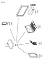
図1は、本発明の実施例が適用されることができる一般的な無線LAN(Wireless Local Area Network;WLAN)システムの構成を示す。 FIG. 1 shows a configuration of a general wireless local area network (WLAN) system to which an embodiment of the present invention can be applied.
図1を参照すると、無線LANシステムは、一つ又はそれ以上の基本サービスセット(Basic Service Set、BSS)を含む。BSSは、成功的に同期化を行われて互いに通信できるステーション(Station、STA)の集合であり、特定領域を示す概念ではない。 Referring to FIG. 1, the wireless LAN system includes one or more basic service sets (BSS). The BSS is a set of stations (Stations, STAs) that can successfully communicate with each other and is not a concept indicating a specific area.
インフラストラクチャー(infrastructure)BSSは、一つ又はそれ以上の非APステーション(non−AP STA1、non−AP STA2、non−AP STA3、non−AP STA4、non−AP STAa)、分散サービス(Distribution Service)を提供するAP(Access Point)10及び複数のAPを連結させる分散システム(Distribution System、DS)を含む。インフラストラクチャーBSSでは、APがBSSの非AP STAを管理する。 Infrastructure BSS is one or more non-AP stations (non-AP STA1, non-AP STA2, non-AP STA3, non-AP STA4, non-AP STAa), distributed service (Distribution Service) And an AP (Access Point) 10 that provides a plurality of APs (Distribution System, DS). In the infrastructure BSS, the AP manages the non-AP STAs of the BSS.
それに対し、独立BSS(Independent BSS、IBSS)は、アドホック(Ad−Hoc)モードで動作するBSSである。IBSSは、APを含まないため、中央で管理機能を遂行するエンティティ(Centralized Management Entity)がない。即ち、IBSSでは、非AP STAが分散された方式(distributed manner)に管理される。IBSSでは、全てのSTAが移動STAからなることができ、DSへの接続が許容されなくて自己完備的ネットワーク(self−contained network)を構築する。 On the other hand, an independent BSS (Independent BSS, IBSS) is a BSS that operates in an ad hoc (Ad-Hoc) mode. Since the IBSS does not include an AP, there is no entity (Centralized Management Entity) that performs a management function in the center. That is, in IBSS, non-AP STAs are managed in a distributed manner. In IBSS, all STAs can consist of mobile STAs, and connection to the DS is not allowed, and a self-contained network is built.
STAは、IEEE(Institute of Electrical and Electronics Engineers)802.11標準の規定に従う媒体接続制御(Medium Access Control、MAC)と無線媒体に対する物理層(Physical Layer)インターフェースを含む任意の機能媒体であって、広義ではAPと非APステーション(Non−AP Station)の両方ともを含む。 The STA is an arbitrary function including a medium layer control (Medium Access Control, MAC) and a physical layer (Physical Layer) interface according to the specifications of the IEEE (Institut of Electrical and Electronics Engineers) 802.11 standard. In a broad sense, both an AP and a non-AP station are included.
非AP STAは、APでないSTAであって、移動端末(mobile terminal)、無線機器(wireless device)、無線送受信ユニット(Wireless Transmit/Receive Unit;WTRU)、ユーザ装備(User Equipment;UE)、移動局(Mobile Station;MS)、移動加入者局ユニット(Mobile Subscriber Unit)又は単純にユーザ(user)などとも呼ばれる。以下、説明の便宜のために、非AP STAをSTAという。 A non-AP STA is a STA that is not an AP, and includes a mobile terminal, a wireless device, a wireless transmission / reception unit (WTRU), a user equipment (User Equipment; UE), and a mobile station. Also referred to as (Mobile Station; MS), Mobile Subscriber Unit, or simply user. Hereinafter, non-AP STAs are referred to as STAs for convenience of explanation.
APは、該当APに結合された(Associated)STAのために、無線媒体を経由してDSに対する接続を提供する機能エンティティである。APを含むインフラストラクチャーBSSにおいて、STA間の通信は、APを経由して行われることが原則であるが、ダイレクトリンクが設定された場合はSTA間でも直接通信が可能である。APは、集中制御器(central controller)、基地局(Base Station、BS)、ノード−B、BTS(Base Transceiver System)、サイト制御器又は管理STAなどとも呼ばれる。 An AP is a functional entity that provides a connection to a DS via a wireless medium for an associated STA. In an infrastructure BSS including an AP, in principle, communication between STAs is performed via the AP. However, when a direct link is set, direct communication between STAs is also possible. The AP is also called a central controller, a base station (BS), a node-B, a BTS (Base Transceiver System), a site controller, or a management STA.
図1に示すBSSを含む複数のインフラストラクチャーBSSは、分散システム(Distribution System;DS)を介して相互連結されることができる。DSを介して連結された複数のBSSを拡張サービスセット(Extended Service Set;ESS)という。ESSに含まれるAP及び/又はSTAは、互いに通信でき、同じESSで、STAは、シームレス通信しながら一つのBSSから他のBSSに移動できる。 A plurality of infrastructure BSSs including the BSS shown in FIG. 1 can be interconnected via a distributed system (DS). A plurality of BSSs connected through the DS are referred to as an extended service set (ESS). APs and / or STAs included in the ESS can communicate with each other, and with the same ESS, STAs can move from one BSS to another BSS while performing seamless communication.
IEEE802.11による無線LANシステムにおいて、MAC(Medium Access Control)の基本接続メカニズムは、CSMA/CA(Carrier Sense Multiple Access with Collision Avoidance)メカニズムである。CSMA/CAメカニズムは、IEEE802.11MACの分配調整機能(Distributed Coordination Function、DCF)とも呼ばれ、基本的に“listen before talk”接続メカニズムを採用している。このような類型の接続メカニズムによると、AP及び/又はSTAは、送信開始以前に無線チャネル又は媒体(medium)をセンシング(sensing)する。センシング結果、もし、媒体がアイドル状態(idle status)であると判断されると、該当媒体を介してフレームの送信を開始する。それに対し、媒体が占有状態(occupied status)であると判断されると、該当AP及び/又はSTAは、自分の送信を開始せずに媒体接近のための遅延期間を設定して待つ。 In a wireless LAN system based on IEEE 802.11, a basic connection mechanism of MAC (Medium Access Control) is a CSMA / CA (Carrier Sense Multiple Access Collision Avidance) mechanism. The CSMA / CA mechanism is also called a distributed coordination function (DCF) of IEEE 802.11 MAC, and basically employs a “listen before talk” connection mechanism. According to this type of connection mechanism, the AP and / or STA senses a radio channel or medium before transmission starts. As a result of sensing, if it is determined that the medium is in an idle state, transmission of a frame is started via the corresponding medium. On the other hand, if it is determined that the medium is in an occupied status, the AP and / or STA sets a delay period for approaching the medium without starting its own transmission and waits.
CSMA/CAメカニズムは、AP及び/又はSTAが媒体を直接センシングする物理的キャリアセンシング(physical carrier sensing)外に仮想キャリアセンシング(virtual carrier sensing)も含む。仮想キャリアセンシングは、ヒドンノード問題(hidden node problem)などのように媒体接近上発生できる問題を補完するためのことである。仮想キャリアセンシングのために、無線LANシステムのMACは、ネットワーク割当ベクトル(Network Allocation Vector、NAV)を利用する。NAVは、現在媒体を使用している、又は使用する権限のあるAP及び/又はSTAが、媒体が利用可能な状態になるまで残っている時間を他のAP及び/又はSTAに指示する値である。したがって、NAVで設定された値は、該当フレームを送信するAP及び/又はSTAにより媒体の使用が予定されている期間に該当する。 The CSMA / CA mechanism includes virtual carrier sensing in addition to physical carrier sensing in which the AP and / or STA directly senses the medium. The virtual carrier sensing is for complementing a problem that can occur when the medium approaches, such as a hidden node problem. For virtual carrier sensing, the MAC of the wireless LAN system uses a network allocation vector (NAV). The NAV is a value that indicates to other APs and / or STAs how long the AP and / or STA that is currently using or authorized to use the medium will be able to use the medium. is there. Therefore, the value set in the NAV corresponds to a period during which the medium is scheduled to be used by the AP and / or STA that transmits the corresponding frame.
DCFと共にIEEE802.11MACプロトコルは、DCFとポーリング(pollling)に基づく同期式接続方式として、全ての受信AP及び/又はSTAがデータパケットを受信することができるように周期的にポーリングするPCF(Point Coordination Function)に基づくHCF(Hybrid Coordination Function)を提供する。HCFは、提供者が多数のユーザにデータパケットを提供するための接続方式をコンテンションベースにするEDCA(Enhanced Distributed Channel Access)と、ポーリング(polling)メカニズムを利用した非コンテンションベースのチャネル接近方式を使用するHCCA(HCF Controlled Channel Access)とを有する。HCFは、無線LANのQoS(Quality of Service)を向上させるための媒体接近メカニズムを含み、コンテンション周期(Contention Period;CP)と非コンテンション周期(Contention Free Period;CFP)の両方ともでQoSデータを送信することができる。 The IEEE 802.11 MAC protocol together with DCF is a PCF (Point Coordination) that periodically polls all receiving APs and / or STAs to receive data packets as a synchronous connection method based on DCF and polling. An HCF (Hybrid Coordination Function) based on the Function is provided. HCF is a contention-based connection method for providing data packets to a large number of users by EDCA (Enhanced Distributed Channel Access) and a non-contention-based channel access method using a polling mechanism. With HCCA (HCF Controlled Channel Access). The HCF includes a medium access mechanism for improving QoS (Quality of Service) of a wireless LAN, and QoS data is obtained in both a contention period (CP) and a non-contention period (CFP). Can be sent.
無線通信システムでは、無線媒体の特性上、STAの電源が付けられて動作を開始する時、ネットワークの存在が即時分からない。したがって、どのようなタイプのSTAもネットワークに接続をするためにはネットワーク検出(network discovery)過程を実行しなければならない。ネットワーク検出過程を介してネットワークを検出したSTAは、ネットワーク選択過程を介して加入するネットワークを選択する。その後、選択したネットワークに加入して送信端/受信端で行われるデータ交換動作を実行する。 In the wireless communication system, due to the characteristics of the wireless medium, the existence of the network is not immediately known when the STA is powered on and starts operation. Therefore, any type of STA has to perform a network discovery process in order to connect to the network. The STA that detects the network through the network detection process selects a network to join through the network selection process. Thereafter, the data exchange operation performed at the transmitting end / receiving end is performed by joining the selected network.
無線LANシステムにおいて、ネットワーク検出過程は、スキャニング手順(scanning procedure)で具現される。スキャニング手順は、受動スキャニング(passive scanning)と能動スキャニング(active scanning)とに分けられる。受動スキャニングは、APが周期的にブロードキャスト(broadcast)するビーコンフレーム(beacon frame)に基づいて行われる。一般的に、無線LANのAPは、ビーコンフレームを特定インターバル(interval)(例えば、100msec)毎にブロードキャストする。ビーコンフレームは、自分が管理するBSSに対する情報を含む。STAは、受動的に、特定チャネルでビーコンフレームの受信のために待機する。ビーコンフレームの受信を介してネットワークに対する情報を取得したSTAは、特定チャネルでのスキャニング手順を終了する。受動スキャニングは、STAが別途のフレームを送信する必要無しでビーコンフレームを受信すると行われるため、全体的なオーバーヘッドが少ないという長所がある。しかし、ビーコンフレームの送信周期に比例してスキャニング実行時間が増えるという短所がある。 In the wireless LAN system, the network detection process is implemented by a scanning procedure. The scanning procedure is divided into passive scanning and active scanning. The passive scanning is performed based on a beacon frame that the AP periodically broadcasts. In general, a wireless LAN AP broadcasts a beacon frame at specific intervals (for example, 100 msec). The beacon frame includes information on the BSS managed by the beacon frame. The STA passively waits for reception of a beacon frame on a specific channel. The STA that has acquired information about the network through reception of the beacon frame ends the scanning procedure on the specific channel. Passive scanning is performed when the STA receives a beacon frame without the need to transmit a separate frame, and thus has an advantage of low overall overhead. However, the scanning execution time increases in proportion to the transmission period of the beacon frame.
能動スキャニングは、STAが能動的に特定チャネルでプローブ要求フレーム(probe request frame)をブロードキャストし、これを受信した全てのAPからネットワーク情報を要求することである。プローブ要求フレームを受信したAPは、フレーム衝突を防止するために、ランダム時間待機後、プローブ応答フレームにネットワーク情報を含ませて該当STAに送信する。STAは、プローブ応答フレームを受信してネットワーク情報を取得することによってスキャニング手順を終了する。能動スキャニングは相対的に速い時間内にスキャニングを終えることができるという長所を有する。それに対し、要求−応答によるフレームシーケンスが必要であるため、全体的なネットワークオーバーヘッドは増加するようになる。 Active scanning is when a STA actively broadcasts a probe request frame on a specific channel and requests network information from all APs that have received the probe request frame. In order to prevent frame collision, the AP that has received the probe request frame waits for a random time and then transmits the probe response frame including the network information to the corresponding STA. The STA ends the scanning procedure by receiving the probe response frame and acquiring network information. Active scanning has the advantage that scanning can be completed within a relatively fast time. On the other hand, since a frame sequence by request-response is necessary, the overall network overhead is increased.
スキャニング手順を終えたSTAは、自分に対する特定基準によってネットワークを選択した後、APと認証(authentication)手順を実行する。認証手順は、2方向ハンドシェイク(2−way handshake)で行われる。認証手順を終えたSTAは、APと結合(association)手順を進行する。 After completing the scanning procedure, the STA selects a network according to a specific criterion for the STA, and then performs an authentication procedure with the AP. The authentication procedure is performed by a two-way handshake (2-way handshake). After completing the authentication procedure, the STA proceeds with the association procedure with the AP.
結合手順は、2方向ハンドシェイクで行われる。まず、STAがAPに結合要求フレーム(association request frame)を送信する。結合要求フレームにはSTAの能力値(capabilities)情報が含まれる。これに基づいて、APは、該当STAに対する結合許容可否を決定する。結合許容可否を決定したAPは、該当STAに結合応答フレーム(association response frame)を送信する。結合応答フレームは、結合許容可否を指示する情報及び結合許容/失敗時、理由を指示する情報を含む。結合応答フレームは、APがサポート可能な能力値に対する情報をさらに含む。結合が成功的に完了した場合、APとSTAとの間の正常なフレーム交換が行われる。結合が失敗した場合、結合応答フレームに含まれている失敗理由に対する情報に基づいて結合手順が再び試みられ、又は、STAは、他のAPに結合を要求することができる。 The combining procedure is performed with a two-way handshake. First, the STA transmits an association request frame to the AP. The join request frame includes STA capability information. Based on this, the AP determines whether or not to allow the connection to the corresponding STA. The AP that has determined whether or not the connection is allowed transmits a connection response frame to the corresponding STA. The combination response frame includes information indicating whether or not the connection is allowed and information indicating the reason when the connection is allowed / failed. The combined response frame further includes information on capability values that the AP can support. If the association is completed successfully, a normal frame exchange between the AP and the STA is performed. If the join fails, the join procedure is retried based on the failure reason information contained in the join response frame, or the STA can request another AP to join.
無線LANで脆弱点と指摘された通信速度に対する限界を克服するために、比較的最近制定された技術規格としてIEEE802.11nがある。IEEE802.11nは、ネットワークの速度と信頼性を増加させ、無線ネットワークの運営距離を拡張することを目的とする。より具体的に、IEEE802.11nでは、データ処理速度が最大540Mbps以上である高処理率(High Throughput、HT)をサポートし、また、送信エラーを最小化してデータ速度を最適化するために、送信部と受信部の両端ともに多重アンテナを使用するMIMO(Multiple Inputs and Multiple Outputs)技術に基づいている。 In order to overcome the limitation on communication speed, which has been pointed out as a weak point in wireless LAN, there is IEEE 802.11n as a relatively recent technical standard. IEEE 802.11n aims to increase network speed and reliability and extend the operating distance of wireless networks. More specifically, IEEE 802.11n supports a high processing rate (High Throughput, HT) with a maximum data processing speed of 540 Mbps or higher, and also transmits data to optimize transmission speed by minimizing transmission errors. This is based on the MIMO (Multiple Inputs and Multiple Outputs) technology that uses multiple antennas at both ends of the receiver and receiver.
無線LANの普及が活性化され、また、これを利用したアプリケーションが多様化されるにつれて、最近、IEEE802.11nがサポートするデータ処理速度より高い処理率をサポートするための新たな無線LANシステムに対する必要性が台頭されている。超高処理率(Very High Throughput、VHT)をサポートする無線LANシステムは、IEEE802.11n無線LANシステムの次のバージョンであり、MACサービス接続ポイント(Service Access Point、SAP)でマルチユーザに対して1Gbps以上のデータ処理速度、そして、シングルユーザに対しては500Mbps以上の処理率をサポートするために最近新たに提案されているIEEE802.11無線LANシステムのうち一つである。 As the spread of wireless LANs is activated and the applications that use them are diversified, the need for new wireless LAN systems to support higher processing rates than the data processing speeds supported by IEEE 802.11n recently. Sex is emerging. A wireless LAN system that supports very high throughput (VHT) is the next version of the IEEE 802.11n wireless LAN system, and is 1 Gbps for multi-users at the MAC service connection point (Service Access Point, SAP). This is one of the IEEE802.11 wireless LAN systems recently proposed to support the above data processing speed and a processing rate of 500 Mbps or more for a single user.
VHT無線LANシステムでは、20MHz、40MHzをサポートした既存無線LANシステムより、80MHz、連続的な160MHz(contiguous 160MHz)、不連続的な160MHz(non−contiguous 160MHz)帯域幅送信及び/又はそれ以上の帯域幅送信をさらにサポートしようとする。ひいては、最大64QAM(Quadrature Amplitude Modulation)をサポートした既存無線LANシステムより、256QAMをさらにサポートする。 In the VHT wireless LAN system, 80 MHz, continuous 160 MHz (continuous 160 MHz), discontinuous 160 MHz (non-contiguous 160 MHz) bandwidth transmission and / or higher bandwidth than existing wireless LAN systems that support 20 MHz and 40 MHz. Attempts to further support width transmission. As a result, 256QAM is further supported from the existing wireless LAN system that supports a maximum of 64QAM (Quadrature Amplitude Modulation).
VHT無線LANシステムは、より高い処理率のために、MU−MIMO(MultiUser−Multiple Input Multiple Output)送信方法をサポートするため、APは、MIMOペアリングされた少なくとも一つ以上のSTAに同時にデータフレームを送信することができる。ペアリングされたSTAの数は最大4個であり、最大空間ストリーム数が8個である時、各STAには最大4個の空間ストリームが割り当てられることができる。 Since the VHT wireless LAN system supports a MU-MIMO (MultiUser-Multiple Input Multiple Output) transmission method for a higher processing rate, the AP can simultaneously transmit data frames to at least one or more MIMO-paired STAs. Can be sent. When the number of paired STAs is 4 at the maximum and the maximum number of spatial streams is 8, a maximum of 4 spatial streams can be allocated to each STA.
また、図1を参照すると、図面のような無線LANシステムにおいて、AP10は、自分と結合(association)されている複数のSTA21、22、23、24、30のうち少なくとも一つ以上のSTAを含むSTAグループにデータを同時に送信することができる。図1では、APがSTAにMU−MIMO送信することを例示しているが、TDLS(Tunneled Direct Link Setup)又はDLS(Direct Link Setup)、メッシュネットワーク(mesh network)をサポートする無線LANシステムでは、データを送信しようとするSTAがMU−MIMO送信技法を使用してPPDUを複数のSTAに送信することができる。以下、APが複数のSTAにMU−MIMO送信技法によってPPDUを送信することを例示して説明する。
Referring to FIG. 1, in the wireless LAN system as shown in the drawing, the
各々のSTAに送信されるデータは、互いに異なる空間ストリーム(spatial stream)を介して送信されることができる。AP10が送信するデータパケットは、無線LANシステムの物理階層で生成されて送信されるPPDU又はPPDUに含まれているデータフィールドであり、フレームと言及されることができる。即ち、SU(single user)−MIMO及び/又はMU−MIMOのためのPPDU又はPPDUに含まれているデータフィールドをMIMOパケットということができる。そのうち、MUのためのPPDUをMUパケットということができる。本発明の例示において、AP10とMU−MIMOペアリングされた送信対象STAグループは、STA1、STA2、STA3及びSTA4と仮定する。このとき、送信対象STAグループの特定STAには空間ストリームが割り当てられなくてデータが送信されない。一方、STAaは、APと結合されているが、送信対象STAグループには含まれないSTAであると仮定する。
Data transmitted to each STA may be transmitted via different spatial streams. The data packet transmitted by the
無線LANシステムにおいて、MU−MIMO送信をサポートするために、送信対象STAグループに対して識別子が割り当てられることができ、これをグループ識別子(Group ID)という。APは、MU−MIMO送信をサポートするSTAにグループID割当のためにグループ定義情報(group definition information)を含むグループID管理フレーム(Group ID management frame)を送信し、これによって、グループIDは、PPDU送信以前にSTAに割り当てられる。一つのSTAは、複数個のグループIDの割当を受けることができる。 In the wireless LAN system, in order to support MU-MIMO transmission, an identifier can be assigned to a transmission target STA group, which is called a group identifier (Group ID). The AP transmits a group ID management frame including group definition information for group ID allocation to a STA that supports MU-MIMO transmission, whereby the group ID is PPDU. Assigned to STA before transmission. One STA can be assigned a plurality of group IDs.
以下の表1は、グループID管理フレームに含まれている情報要素を示す。 Table 1 below shows information elements included in the group ID management frame.

カテゴリフィールド及びVHTアクションフィールドは、該当フレームの管理フレームに該当し、MU−MIMOをサポートする次世代無線LANシステムで使われるグループID管理フレームであることを識別することができるように設定される。 The category field and the VHT action field correspond to the management frame of the corresponding frame, and are set so that it can be identified as a group ID management frame used in the next-generation wireless LAN system that supports MU-MIMO.
表1のように、グループ定義情報は、特定グループIDに属しているかどうかを指示するメンバーシップ状態情報と、該当グループIDに属する場合、該当STAの空間ストリームセットがMU−MIMO送信による全体空間ストリームで何番目に位置に該当するかを指示する空間ストリーム位置情報とを含む。 As shown in Table 1, the group definition information includes membership status information that indicates whether the group belongs to a specific group ID. And spatial stream position information indicating the position corresponding to the position.
一つのAPが管理するグループIDは、複数個であるため、一つのSTAに提供されるメンバーシップ状態情報は、APにより管理されるグループIDの各々にSTAが属しているかどうかを指示する必要がある。したがって、メンバーシップ状態情報は、各グループIDに属しているかどうかを指示するサブフィールドのアレイ(array)形態で存在できる。空間ストリーム位置情報は、グループIDの各々に対する位置を指示するため、各グループIDに対してSTAが占める空間ストリームセットの位置を指示するサブフィールドのアレイ形態で存在できる。また、一つのグループIDに対するメンバーシップ状態情報及び空間ストリーム位置情報は、一つのサブフィールド内で具現が可能でありえる。 Since there are a plurality of group IDs managed by one AP, the membership status information provided to one STA needs to indicate whether the STA belongs to each of the group IDs managed by the AP. is there. Therefore, the membership status information can exist in the form of an array of subfields that indicate whether it belongs to each group ID. Since the spatial stream position information indicates a position for each group ID, it can exist in an array form of subfields that indicate the position of the spatial stream set occupied by the STA for each group ID. Also, membership status information and spatial stream position information for one group ID can be implemented in one subfield.
APは、MU−MIMO送信技法を介してPPDUを複数のSTAに送信する場合、PPDU内にグループ識別子(Group ID)を指示する情報を制御情報として含んで送信する。STAは、PPDUを受信すると、グループIDフィールドを確認することで、自分が送信対象STAグループのメンバーSTAであるかどうかを確認する。自分が送信対象STAグループのメンバーであると確認されると、自分に送信される空間ストリームセットが全体空間ストリームで何番目に位置するかを確認することができる。PPDUは、受信STAに割り当てられた空間ストリームの個数情報を含むため、STAは、自分に割り当てられた空間ストリームを探してデータを受信することができる。 When transmitting a PPDU to a plurality of STAs via the MU-MIMO transmission technique, the AP transmits information indicating a group identifier (Group ID) in the PPDU as control information. When the STA receives the PPDU, the STA confirms whether it is a member STA of the transmission target STA group by confirming the group ID field. If it is confirmed that the user is a member of the transmission target STA group, it is possible to check the position of the spatial stream set transmitted to the user in the overall spatial stream. Since the PPDU includes information on the number of spatial streams assigned to the receiving STA, the STA can search for the spatial stream assigned to itself and receive data.
一方、無線LANシステムにおいて、新たに使用できる周波数帯域としてTV WS(White Space)が注目を浴びている。TV WSは、米国のアナログTVのデジタル化により残ったアイドル状態の周波数帯域を意味し、例えば、54〜698MHz帯域である。しかし、これは例示に過ぎず、TV WSは、許可されたユーザ(licensed user)が優先的に使用することができる許可された帯域である。許可されたユーザは、許可された帯域の使用に対して許可を受けたユーザを意味し、許可された装置(licensed device)、第1のユーザ(primary user)、主ユーザ(incumbent user)などとも呼ばれる。 On the other hand, in the wireless LAN system, TV WS (White Space) is attracting attention as a frequency band that can be newly used. TV WS means an idle state frequency band left by digitization of analog TV in the United States, and is, for example, a band of 54 to 698 MHz. However, this is merely an example, and TV WS is an authorized band that can be used preferentially by authorized users. An authorized user means a user who is authorized to use an authorized band, and is referred to as an authorized device, a primary user, an primary user, or the like. be called.
TV WSで動作するAP及び/又はSTAは、許可されたユーザに対する保護(protection)機能を提供しなければならず、その理由は、TV WS帯域の使用において許可されたユーザが優先するためである。例えば、TV WS帯域で特定帯域幅を有するように規約上分割されている周波数帯域である特定WSチャネルをマイクロフォン(microphone)のような許可されたユーザが既に使用している場合、許可されたユーザを保護するために、AP及び/又はSTAは、該当WSチャネルに該当する周波数帯域は使用することができない。また、AP及び/又はSTAは、現在フレームの送信及び/又は受信のために使用している周波数帯域を許可されたユーザが使用するようになると、該当周波数帯域の使用を中止しなければならない。 APs and / or STAs operating in TV WS must provide protection for authorized users because authorized users have priority in using the TV WS band. . For example, if an authorized user, such as a microphone, is already using a specific WS channel, which is a frequency band that is contractually divided to have a specific bandwidth in the TV WS band, the authorized user Therefore, the AP and / or STA cannot use the frequency band corresponding to the corresponding WS channel. In addition, when an authorized user uses a frequency band currently used for transmission and / or reception of a frame, the AP and / or STA must stop using the corresponding frequency band.
したがって、AP及び/又はSTAは、TV WS帯域内の特定周波数帯域の使用が可能かどうか、即ち、前記周波数帯域に許可されたユーザがいるかいないかを把握する手順が先行されなければならない。特定周波数帯域に許可されたユーザがいるかいないかを把握することをスペクトラムセンシング(spectrum sensing)という。スペクトラムセンシングメカニズムとして、エネルギー探知(energy detection)方式、信号探知(signature detection)方式などが活用される。受信信号の強度が一定値以上の場合、許可されたユーザが使用中であると判断し、又はDTVプリアンブル(preamble)が検出される場合、許可されたユーザが使用中であると判断することができる。 Therefore, the AP and / or STA must be preceded by a procedure for determining whether or not a specific frequency band within the TV WS band can be used, that is, whether or not there is an authorized user in the frequency band. It is called spectrum sensing to grasp whether or not there is a user authorized in a specific frequency band. As a spectrum sensing mechanism, an energy detection method, a signal detection method, or the like is used. If the received signal strength is above a certain value, it is determined that the authorized user is in use, or if the DTV preamble is detected, the authorized user is determined to be in use. it can.
フレーム送受信のために、常にチャネルをセンシングすることは、STAの持続的な電力消耗を引き起こす。受信状態での電力消耗は、送信状態での電力消耗に比べて大きく差がないため、受信状態を維持し続けることは、バッテリで動作するSTAに相対的に多くの電力消耗を発生させる。したがって、無線LANシステムにおいて、STAが持続的に受信待機状態を維持しながらチャネルをセンシングすることは、無線LAN処理率側面で特別な上昇効果無しで非効率的なパワー消耗を引き起こすことができるため、パワー管理(power management)側面で適しない。 Always sensing the channel for frame transmission / reception causes persistent power consumption of the STA. Since the power consumption in the reception state is not much different from the power consumption in the transmission state, maintaining the reception state causes a relatively large amount of power consumption in the battery-operated STA. Therefore, in a wireless LAN system, sensing a channel while the STA continuously maintains a reception standby state can cause inefficient power consumption without a special increase effect in terms of wireless LAN processing rate. This is not suitable in terms of power management.
前記のような問題点を補完するために、無線LANシステムでは、STAのパワー管理(power management;PM)モードをサポートする。STAのパワー管理モードは、アクティブモード(active mode)とパワーセーブ(power save;PS)モードとに分けられる。STAは、基本的に活性化モードで動作する。アクティブモードで動作するSTAは、アウェイク状態(awake state)を維持する。即ち、フレーム送受信やチャネルセンシング等、正常な動作が可能な状態を維持する。 In order to compensate for the above problems, the wireless LAN system supports a STA power management (PM) mode. The power management mode of the STA is divided into an active mode and a power save (PS) mode. The STA basically operates in the activation mode. A STA operating in the active mode maintains an awake state. That is, a state in which normal operation such as frame transmission / reception and channel sensing is possible is maintained.
PSモードで動作するSTAは、ドーズ状態(doze state)とアウェイク状態(awake state)とを切り替えて動作する。ドーズ状態で動作するSTAは、最小限のパワーで動作し、データフレームを含んでAPから送信される無線信号を受信しない。また、ドーズ状態で動作するSTAは、チャネルセンシングを実行しない。 The STA operating in the PS mode operates by switching between a doze state and an awake state. The STA operating in the doze state operates with a minimum power and does not receive a radio signal transmitted from the AP including a data frame. Further, the STA operating in the doze state does not execute channel sensing.
STAは、ドーズ状態で可能の限り長い間動作するほど電力消耗が減るため、動作期間が増加する。しかし、ドーズ状態ではフレーム送受信が不可能であるため、無条件的に長い間動作できない。ドーズ状態で動作するSTAは、APに送信するフレームが存在する場合、アウェイク状態に切り替えてフレームを送信することができる。ただし、APが、ドーズ状態で動作するSTAに送信するフレームがある場合、STAは、これを受信することができず、且つ受信するフレームが存在することも分からない。したがって、STAは、自分に送信されるフレームの存在可否、存在する場合、これを受信するために特定周期によってアウェイク状態に切り替える動作が必要である。APは、これによってフレームをSTAに送信することができる。これは図2を参照して説明する。 As the STA operates for as long as possible in the doze state, the power consumption decreases, and therefore the operation period increases. However, since it is impossible to transmit and receive frames in the doze state, it cannot operate unconditionally for a long time. If there is a frame to be transmitted to the AP, the STA operating in the doze state can switch to the awake state and transmit the frame. However, if there is a frame to be transmitted by the AP to the STA operating in the doze state, the STA cannot receive it and does not know that there is a frame to be received. Accordingly, the STA needs to switch to the awake state according to a specific period in order to receive the presence / absence of a frame to be transmitted to the STA. This allows the AP to send the frame to the STA. This will be described with reference to FIG.
図2は、パワー管理運営(power management operation)の一例を示す。 FIG. 2 shows an example of power management operation.
図2を参照すると、AP210は、一定周期にビーコンフレーム(beacon frame)をBSS内のSTAに送信する(S210)。ビーコンフレームには、TIM情報要素(traffic indication map information element)が含まれる。TIM要素は、AP210が自分と結合されたSTAに対するバッファ可能なフレーム(Bufferable frame又はBufferable Unit;BU)がバッファされており、フレームを送信することを知らせる情報を含む。TIM要素には、ユニキャスト(unicast)フレームを知らせるのに使われるTIMと、マルチキャスト(multicast)又はブロードキャスト(broadcast)フレームを知らせるのに使われるDTIM(delivery traffic indication map)とがある。
Referring to FIG. 2, the
AP210は、3回のビーコンフレームを送信する時毎に1回ずつDTIMを送信する。
The
STA1及びSTA2は、PSモードで動作するSTAである。STA1及びSTA2は、特定周期のウェイクアップインターバル(wakeup interval)毎にドーズ状態からアウェイク状態に切り替え、AP210によって送信されたTIM要素を受信することができるように設定されることができる。
STA1 and STA2 are STAs that operate in the PS mode. The STA1 and the STA2 may be configured to switch from the doze state to the awake state at every wakeup interval of a specific period and to receive the TIM element transmitted by the
STA1がビーコンインターバル(beacon interval)毎にアウェイク状態に切り替えてTIM要素を受信することができるように特定ウェイクアップインターバルが設定されることができる。したがって、STA1は、AP210が1番目にビーコンフレームを送信する時(S211)、アウェイク状態に切り替える(S221)。STA1は、ビーコンフレームを受信し、TIM要素を取得する。取得されたTIM要素がSTA1に送信されるバッファ可能なフレームがバッファされていることを指示する場合、STA1は、AP210にフレームの送信を要求するPSポール(PS poll)フレームをAP210に送信する(S221a)。AP210は、PSポールフレームに対応してフレームをSTA1に送信する(S231)。フレーム受信を完了したSTA1は、再びドーズ状態に切り替えて動作する。
A specific wakeup interval may be set so that STA1 can switch to an awake state at every beacon interval and receive a TIM element. Therefore, when the
AP210が2番目にビーコンフレームを送信するにあたって、他の装置が媒体に接近している等、媒体(medium)が占有された(busy)状態であるため、AP210は、正確なビーコンインターバルに合わせてビーコンフレームを送信することができなくて遅延された時点に送信することができる(S212)。この場合、STA1は、ビーコンインターバルに合わせて動作モードをアウェイク状態に切り替えるが、遅延されて送信されるビーコンフレームを受信することができなくて再びドーズ状態に切り替える(S222)。
When the
AP210が3番目にビーコンフレームを送信する時、該当ビーコンフレームにはDTIMに設定されたTIM要素が含まれることができる。ただし、媒体が占有された状態であるため、AP210は、ビーコンフレームを遅延送信する(S213)。STA1は、ビーコンインターバルに合わせてアウェイク状態に切り替えて動作し、AP210により送信されるビーコンフレームを介してDTIMを取得することができる。STA1が取得したDTIMは、STA1に送信されるフレームはなく、且つ他のSTAのためのフレームが存在することを指示するため、STA1は、再びドーズ状態に切り替えて動作する。AP210は、ビーコンフレームの送信後、フレームを該当STAに送信する(S232)。
When the
AP210は、4番目にビーコンフレームを送信する(S214)。ただし、STA1は、以前の2回のTIM要素の受信を介して自分に対するバッファ可能なフレームがバッファされているという情報を取得することができないため、TIM要素の受信のためのウェイクアップインターバルを調整することができる。または、STA1のウェイクアップインターバル値を調整のためのシグナリング情報が、AP210により送信されるビーコンフレームに含まれている場合、STA1のウェイクアップインターバル値が調整されることができる。本例示において、STA1は、ビーコンインターバル毎にTIM要素の受信のために運営状態を切り替えたことを、3回のビーコンインターバル毎に運営状態を一回切り替えるように設定されることができる。したがって、STA1は、AP210が4番目のビーコンフレームを送信し(S214)、5番目のビーコンフレームを送信する時点に(S215)ドーズ状態を維持するため、該当TIM要素を取得することができない。
The
AP210が6番目にビーコンフレームを送信する時(S216)、STA1は、アウェイク状態に切り替えて動作し、ビーコンフレームに含まれているTIM要素を取得する(S224)。TIM要素は、ブロードキャストフレームが存在することを指示するDTIMであるため、STA1は、PSポールフレームをAP210に送信せずに、AP210により送信されるブロードキャストフレームを受信する(S234)。
When the
一方、STA2に設定されたウェイクアップインターバルは、STA1より長い周期に設定されることができる。したがって、STA2は、AP210が5番目にビーコンフレームを送信する時点(S215)にアウェイク状態に切り替えてTIM要素を受信することができる(S225)。STA2は、TIM要素を介して自分に送信されるフレームが存在することが分かり、送信を要求するために、AP210にPSポールフレームを送信する(S225a)。AP210は、PSポールフレームに対応してSTA2にフレームを送信する(S233)。
On the other hand, the wakeup interval set for STA2 can be set to a longer period than STA1. Therefore, the STA2 can switch to the awake state and receive the TIM element (S225) when the
図2のようなパワーセーブモード運営のために、TIM要素にはSTAが自分に送信されるフレームが存在するかどうかを指示するTIM又はブロードキャスト/マルチキャストフレームが存在するかどうかを指示するDTIMが含まれる。DTIMは、TIM要素のフィールド設定を介して具現されることができる。 For power save mode operation as shown in FIG. 2, the TIM element includes a TIM indicating whether there is a frame transmitted to the STA or a DTIM indicating whether there is a broadcast / multicast frame. It is. The DTIM can be implemented through the field setting of the TIM element.
図3は、TIM要素フォーマットの一例を示すブロック図である。 FIG. 3 is a block diagram illustrating an example of a TIM element format.
図3を参照すると、TIM要素300は、要素IDフィールド310、長さフィールド320、DTIMカウント(count)フィールド330、DTIM周期(period)フィールド340、ビットマップ制御(bitmap control)フィールド350及び部分仮想ビットマップ(partial virtual bitmap)フィールド360を含む。
Referring to FIG. 3, a
要素IDフィールド310は、該当情報要素がTIM要素であることを指示するフィールドである。長さフィールド320は、自分を含んで以後のフィールドを含む全体長さを指示する。最大値は255であり、単位はオクテット値に設定されることができる。
The
DTIMカウントフィールド330は、現在のTIM要素がDTIMかどうかを知らせ、DTIMでない場合はDTIMが送信される時まで残ったTIMの個数を指示する。DTIM周期フィールド340は、DTIMが送信される周期を指示し、DTIMが送信される周期は、ビーコンフレームが送信される回数の倍数に設定されることができる。
The
ビットマップ制御フィールド350及び部分仮想ビットマップフィールド360は、特定STAにバッファ可能なフレームがバッファされているかどうかを指示する。ビットマップ制御フィールド350の1番目のビットは、送信されるマルチキャスト/ブロードキャストフレームが存在するかどうかを指示する。残りのビットは、以後の部分仮想ビットマップフィールド360を解釈するためのオフセット値を指示するように設定される。
The
部分仮想ビットマップフィールド360は、各STAに送るバッファ可能なフレームがあるかどうかを指示する値に設定される。これは特定STAのAID値に該当するビット値を1に設定するビットマップ形式に設定されることができる。AID順序によって1から2007まで順序通りに割り当てられることができ、一例として、4番目のビットが1に設定されると、AIDが4であるSTAに送るトラフィックがAPにバッファされていることを意味する。
The partial
一方、部分仮想ビットマップフィールド360のビットシーケンスを設定するにあたって、0に設定されたビットが連続で続く場合が多い状況にはビットマップを構成する全てのビットシーケンスを使用することは非効率的である。そのために、ビットマップ制御フィールド350に部分仮想ビットマップフィールド360のためのオフセット情報が含まれることができる。
On the other hand, when setting the bit sequence of the partial
図4は、本発明の実施例に係るビットマップ制御フィールドと部分仮想ビットマップフィールドの一例を示す。 FIG. 4 shows an example of a bitmap control field and a partial virtual bitmap field according to an embodiment of the present invention.
図4を参照すると、部分仮想ビットマップフィールド360を構成するビットマップシーケンスは、該当ビットマップインデックスに該当するAIDを有するSTAにバッファされたフレームがあるかどうかを指示する。ビットマップシーケンスは、0〜2007のAIDに対する指示情報を構成する。
Referring to FIG. 4, the bitmap sequence forming the partial
ビットマップシーケンスは、最初のビットからk番目のビットまで0値が連続的に設定されることができる。また、他の1番目のビットから最後のビットまで0値が連続的に設定されることができる。これはAIDとして0〜kの割当を受けた各々のSTA及び1〜2007の割当を受けた各々のSTAには、バッファされたフレームが存在しないことを指示する。このように、ビットマップシーケンスの前端の0〜k番目までの連続的な0シーケンスは、オフセット情報の提供により、後端の連続的な0シーケンスを省略すると、TIM要素の大きさを減らすことができる。 In the bitmap sequence, 0 values can be continuously set from the first bit to the k-th bit. Also, a zero value can be set continuously from the other first bit to the last bit. This indicates that there is no buffered frame in each STA that has been assigned an AID of 0-k and each STA that has been assigned an assignment of 1-2007. In this way, the continuous 0 sequence from 0 to kth at the front end of the bitmap sequence can reduce the size of the TIM element by omitting the continuous 0 sequence at the rear end by providing offset information. it can.
そのために、ビットマップ制御フィールド350にはビットマップシーケンスの連続的な0シーケンスのオフセット情報を含むビットマップオフセット(bitmap offset)サブフィールド351が含まれることができる。ビットマップオフセットサブフィールド351は、kを示すように設定されることができ、部分仮想ビットマップフィールド360は、元来l−1番目のビットまでを含むように設定されることができる。
To that end, the
TIM要素を受信したSTAの詳細な応答手順は、以下の図5乃至図7を参照することができる。 The detailed response procedure of the STA that receives the TIM element can be referred to FIGS. 5 to 7 below.
図5は、TIMプロトコルでAPの応答手順の一例を示す流れ図である。 FIG. 5 is a flowchart showing an example of an AP response procedure in the TIM protocol.
図5を参照すると、STA520は、AP510からTIMを含むビーコンフレームを受信するために、ドーズ状態からアウェイク状態に運営状態を切り替える(S510)。STA520は、受信したTIM要素を解釈して自分に送信されるバッファされたフレームがあることが分かる。
Referring to FIG. 5, the
STA520は、PSポールフレームの送信のための媒体接近のために、他のSTAとコンテンション(contending)し(S520)、AP510にデータフレームの送信を要求するために、PSポールフレームを送信する(S530)。
The
STA520により送信されたPSポールフレームを受信したAP510は、STA520にデータフレームを送信する(S540)。STA2520は、データフレームを受信し、これに対する受信応答としてACK(acknowledgement)フレームをAP510に送信する(S550)。以後、STA2520は、再びドーズ状態に運営モードを切り替える(S560)。
The
図5のように、APは、STAからPSポールフレームを受信後直ちにデータフレームを送信する即時応答と違って、PSポールフレーム受信以後、特定時点にデータを送信することもできる。 As shown in FIG. 5, unlike an immediate response in which a data frame is transmitted immediately after receiving a PS poll frame from an STA, the AP can also transmit data at a specific time after receiving the PS poll frame.
図6は、TIMプロトコルでAPの応答手順の他の一例を示す流れ図である。 FIG. 6 is a flowchart showing another example of an AP response procedure in the TIM protocol.
図6を参照すると、STA620は、AP610からTIMを含むビーコンフレームを受信するために、ドーズ状態からアウェイク状態に運営状態を切り替える(S610)。STA620は、受信したTIM要素を解釈して自分に送信されるバッファされたフレームがあることが分かる。
Referring to FIG. 6, the
STA620は、PSポールフレームの送信のための媒体接近のために、他のSTAとコンテンションし(S620)、AP610にデータフレームの送信を要求するために、PSポールフレームを送信する(S630)。
The
AP610がPSポールフレームを受信したが、SIFS(short interframe space)のように特定時間のインターバル中にデータフレームを用意していない場合、データフレームを直ちに送信せずに、その代わりにACKフレームをSTA620に送信する(S640)。これは図5のAP510がPSポールフレームに対応してデータフレームを直ちにSTA520に送信するS540ステップと異なる遅延された応答(deferred response)の特徴である。
If the
AP610は、ACKフレームの送信後、データフレームが用意されると、コンテンションを実行した後(S650)、データフレームをSTA620に送信する(S660)。
When the data frame is prepared after transmitting the ACK frame, the
STA620は、データフレームに対する受信応答としてACKフレームをAP610に送信し(S670)、ドーズ状態に運営モードを切り替える(S680)。
The
APがDTIMをSTAに送信すると、以後進行されるTIMプロトコルの手順は異なる。 When the AP transmits a DTIM to the STA, the procedure of the TIM protocol that is subsequently performed is different.
図7は、DTIMによるTIMプロトコルの手順を示す流れ図である。 FIG. 7 is a flowchart showing the procedure of the TIM protocol by DTIM.
図7を参照すると、STA720は、AP710からTIM要素を含むビーコンフレームを受信するために、ドーズ状態からアウェイク状態に運営状態を切り替える(S710)。STA720は、受信したDTIMを介してマルチキャスト/ブロードキャストフレームが送信されることが分かる。
Referring to FIG. 7, the
AP710は、DTIMを含むビーコンフレームの送信後、マルチキャスト/ブロードキャストフレームを送信する(S720)。STA720は、AP710により送信されたマルチキャスト/ブロードキャストフレームを受信した後、再びドーズ状態に運営状態を切り替える(S730)。
After transmitting the beacon frame including DTIM, the
図2乃至図7を参照したTIMプロトコルに基づくパワーセーブモード運営方法において、STAは、TIM要素に含まれているSTA識別情報を介してバッファされたトラフィックによって送信されるバッファされたフレームがあるかどうかを確認することができる。STA識別情報は、STAがAPと結合時に割当を受ける識別子であるAID(Association Identifier)と関連した情報である。STA識別情報は、バッファされたフレームがあるSTAのAIDを直接指示するように設定され、又はAID値に該当するビットオーダーが特定値に設定されるビットマップタイプに設定されることができる。STAは、STA識別情報が自分のAIDを指示すると、自分にバッファされたフレームがあることが分かる。 In the power save mode operating method based on the TIM protocol with reference to FIG. 2 to FIG. 7, is the STA having a buffered frame transmitted by the buffered traffic through the STA identification information included in the TIM element? You can check whether. The STA identification information is information related to an AID (Association Identifier) that is an identifier that is assigned when the STA is associated with the AP. The STA identification information may be set to directly indicate the AID of a STA having a buffered frame, or may be set to a bitmap type in which a bit order corresponding to the AID value is set to a specific value. When the STA identification information indicates its own AID, the STA knows that there is a buffered frame.
一方、ステーションのパワーセーブのために、APSD(Automatic Power Save Delivery)に基づくパワー管理運営も提供されることができる。 Meanwhile, a power management operation based on an APSD (Automatic Power Save Delivery) may be provided for power saving of the station.
APSDをサポートすることができるAPは、ビーコンフレーム、プローブ応答フレーム、及び結合応答フレームの能力値情報フィールドにあるAPSDサブフィールドの使用を介してAPSDをサポートすることができることをシグナリングする。APSDをサポートすることができるSTAは、アクティブモード又はパワーセーブモードで動作するかどうかを指示するために、フレームのフレーム制御フィールドにあるパワー管理フィールドを使用する。 An AP that can support APSD signals that it can support APSD through the use of an APSD subfield in the capability value information field of beacon frames, probe response frames, and combined response frames. STAs that can support APSD use the power management field in the frame control field of the frame to indicate whether to operate in active mode or power save mode.
APSDは、パワーセーブ動作中であるSTAにダウンリンクデータ及びバッファ可能な管理フレームを伝達するためのメカニズムである。APSDを使用中であるパワーセーブモードのSTAにより送信されるフレームは、フレーム制御フィールドのパワー管理ビットを1に設定し、これによって、AP側でのバッファリングが引き起こされることができる。 APSD is a mechanism for transmitting downlink data and bufferable management frames to STAs that are in power saving operation. Frames transmitted by STAs in power save mode that are using APSD set the power management bit in the frame control field to 1, which can cause buffering on the AP side.
APSDは、U−APSD(Unscheduled−APSD)及びS−APSD(Scheduled−APSD)の二つの伝達メカニズム(delivery mechanism)を定義する。STAは、スケジューリングされないSP(Service Period)中、それらのBU(Bufferable Unit)の一部又は全部が伝達されるようにするために、U−APSDを使用することができる。STAは、スケジューリングされたSP中、それらのBUの一部又は全部が伝達されるようにするために、S−APSDを使用することができる。 APSD defines two delivery mechanisms, U-APSD (Unscheduled-APSD) and S-APSD (Scheduled-APSD). The STA can use U-APSD so that a part or all of the BU (Bufferable Unit) is transmitted during an unscheduled SP (Service Period). STAs can use S-APSD to ensure that some or all of their BUs are communicated during the scheduled SP.
U−APSDを使用するSTAは、干渉によってサービス区間中にAPにより送信されたフレームを受信することができない場合もある。たとえ、APは、干渉を感知することができないとしても、STAがフレームを正確に受信することができないと決定することはできる。U−APSD共存能力値は、要求された送信持続時間をSTAがAPに指示し、これをU−APSDのためのサービス区間として使用することができるようにする。APは、サービス区間中にフレームを送信することができ、これによって、STAが干渉を受ける状況でフレームを受信することができる可能性を向上させることができる。また、U−APSDは、サービス区間中にAPが送信したフレームが成功的に受信されない可能性を減らすことができる。 A STA using U-APSD may not be able to receive frames transmitted by the AP during the service interval due to interference. Even if the AP cannot sense the interference, it can determine that the STA cannot receive the frame correctly. The U-APSD coexistence capability value indicates the requested transmission duration to the STA so that it can be used as a service interval for U-APSD. The AP can transmit a frame during the service interval, which can improve the possibility that the STA can receive the frame in a situation where the STA receives interference. Moreover, U-APSD can reduce the possibility that a frame transmitted by the AP during the service interval will not be received successfully.
STAは、U−APSD共存要素(U−APSD Coexistence element)を含むADDTS(Add Traffic Stream)要求フレームをAPに送信する。U−APSD共存要素は、要求されたサービス区間に対する情報を含むことができる。 The STA transmits an Add Traffic Stream (ADDTS) request frame including a U-APSD coexistence element (U-APSD Coexistence element) to the AP. The U-APSD coexistence element may include information for the requested service interval.
APは、要求されたサービス区間に対して処理し、ADDTS要求フレームに対する応答としてADDTS応答フレームを送信することができる。ADDTS要求フレームには状態コードが含まれることができる。状態コードは、前記要求されたサービス区間に対する応答情報を指示することができる。状態コードは、要求されたサービス区間に対する許容可否を指示することができて、要求されたサービス区間に対して拒絶する場合、拒絶の理由をさらに指示することができる。 The AP can process the requested service interval and send an ADDTS response frame as a response to the ADDTS request frame. A status code may be included in the ADDTS request frame. The status code can indicate response information for the requested service interval. The status code can indicate whether or not the requested service period is acceptable, and when rejecting the requested service period, it can further indicate the reason for the rejection.
要求されたサービス区間がAPにより許容された場合、APは、サービス区間中にフレームをSTAに送信することができる。サービス区間の持続時間は、ADDTS要求フレームに含まれているU−APSD共存要素により特定されることができる。サービス区間の開始は、STAがAPにトリガフレーム(trigger frame)を送信してAPが正常に受信した時点である。 If the requested service interval is allowed by the AP, the AP can send a frame to the STA during the service interval. The duration of the service period can be specified by the U-APSD coexistence element included in the ADDTS request frame. The service period starts when the STA transmits a trigger frame to the AP and the AP normally receives the trigger frame.
STAは、U−APSDサービス区間が満了されると、ドーズ状態に進入できる。 The STA can enter the doze state when the U-APSD service period expires.
一方、最近、スマートグリッド(smart grid)、e−Health、ユビキタスのような多様な通信サービスが登場するにつれて、これをサポートするためのM2M(Machine to Machine)技術が脚光を浴びている。温度及び湿度などを感知するセンサと、カメラ、TVなどの家電製品、工場の工程機械、自動車のような大型機械までM2Mシステムを構成する一つの要素になることができる。M2Mシステムを構成する要素は、WLAN通信に基づいてデータを送受信することができる。以下、M2Mシステムを構成する装置がWLANをサポートし、ネットワークを構成した場合、M2M無線LANシステムという。 Meanwhile, as various communication services such as smart grid, e-Health, and ubiquitous have recently appeared, M2M (Machine to Machine) technology for supporting the communication service has been in the spotlight. Sensors that sense temperature and humidity, home appliances such as cameras and TVs, factory process machines, and large machines such as automobiles can be an element that constitutes the M2M system. Elements constituting the M2M system can transmit and receive data based on WLAN communication. Hereinafter, when the devices constituting the M2M system support WLAN and configure a network, the device is referred to as an M2M wireless LAN system.
M2Mをサポートする無線LANシステムでは、1GHz以上の周波数帯域が使われることができ、低い帯域の周波数使用は、サービスカバレッジがより広める特徴が発生することができる。したがって、サービスカバレッジに位置した無線装置の数は、既存無線LANシステムに比べて多くなることができる。これをはじめとして、M2Mをサポートする無線LANシステムの特性は、下記の通りである。 In a wireless LAN system that supports M2M, a frequency band of 1 GHz or more can be used, and the use of a low-band frequency can generate a feature that further expands service coverage. Therefore, the number of wireless devices located in the service coverage can be increased compared to the existing wireless LAN system. Including this, the characteristics of the wireless LAN system that supports M2M are as follows.
1)多いSTAの数:M2Mは、既存のネットワークと違って、多い数のSTAがBSS内に存在することを仮定する。個人が所有した装置だけでなく、ホーム、会社などに設置されたセンサなどを全て考慮するためである。したがって、一つのAPに相当多い数のSTAが接続されることができる。 1) Large number of STAs: Unlike existing networks, M2M assumes that a large number of STAs exist in the BSS. This is to consider not only the devices owned by individuals, but also all sensors installed at homes and companies. Therefore, a considerably large number of STAs can be connected to one AP.
2)各STA当たり低いトラフィック負荷(traffic load):M2M端末は、周辺の情報を収集して報告するトラフィックパターンを有するため、よく送る必要がなく、その情報の量も少ない方である。 2) Low traffic load per STA: M2M terminals have a traffic pattern that collects and reports surrounding information, so they do not need to be sent well and the amount of information is less.
3)アップリンク(uplink)中心の通信:M2Mは、主にダウンリンク(downlink)に命令を受信して行動を取った後、結果データをアップリンクに報告する構造を有する。主要データは、一般的に、アップリンクに送信されるため、M2Mをサポートするシステムではアップリンクが中心になる。 3) Uplink-centric communication: The M2M has a structure of reporting result data to the uplink mainly after receiving commands and taking actions on the downlink. Since the primary data is typically sent on the uplink, the uplink is central in systems that support M2M.
4)STAのパワー管理:M2M端末は、主にバッテリで動作し、ユーザがよく充電しにくい場合が多い。したがって、バッテリ消耗を最小化するためのパワー管理方法が要求される。 4) STA power management: M2M terminals operate mainly on batteries and are often difficult for users to charge. Therefore, a power management method for minimizing battery consumption is required.
5)児童復旧機能:M2Mシステムを構成する装置は、特定状況で人間が直接操作しにくいため、自体的に復旧する機能が必要である。 5) Child recovery function: Since the devices constituting the M2M system are difficult for a human to operate directly in a specific situation, a function to recover itself is necessary.
一般的な無線LANシステムにおけるサーバ(server)/クライアント(client)構造によると、STAのようなクライアントがサーバに情報を要求し、サーバは、要求に対する応答として情報(データ)をSTAに送信することが一般的である。このとき、情報を提供したサーバは、機械的に情報を収集して提供した装置(Machine)と把握することができ、情報を受信した主体は、クライアントを使用したユーザになることができる。このような構造的特性のため既存無線LANシステムではダウンリンク方向の通信技術が主に発展してきた。 According to a server / client structure in a general wireless LAN system, a client such as an STA requests information from the server, and the server transmits information (data) to the STA as a response to the request. Is common. At this time, the server that provided the information can be understood as a device (Machine) that has collected and provided the information mechanically, and the entity that has received the information can be a user who uses the client. Due to such structural characteristics, the communication technology in the downlink direction has been mainly developed in the existing wireless LAN system.
それに対し、M2Mをサポートする無線LANシステムでは、前記のような構造が逆になる。即ち、装置であるクライアントが情報を収集して提供する役割をし、サーバを管理するユーザが情報を要求する役割をするようになる。即ち、M2Mサポート無線LANシステムにおいて、M2Mサーバは、M2M STAに周辺環境測定と関連した命令を下し、M2M STAは、命令によって動作を実行し、収集された情報をサーバに報告する通信流れが一般的である。以前と違って、ユーザがサーバ側でネットワークに接近するようになり、且つ通信の流れが反対方向になるということがM2Mサポート無線LANシステムの構造的特徴になる。 On the other hand, in a wireless LAN system that supports M2M, the above structure is reversed. That is, a client as a device plays a role of collecting and providing information, and a user managing the server plays a role of requesting information. That is, in the M2M supported wireless LAN system, the M2M server issues a command related to the measurement of the surrounding environment to the M2M STA, and the M2M STA performs an operation according to the command and reports the collected information to the server. It is common. Unlike before, it is a structural feature of the M2M supported wireless LAN system that the user comes closer to the network on the server side and the communication flow is in the opposite direction.
前記のような無線LAN環境で、STAは、不要にアウェイク状態を維持することを回避し、バッファされたフレームがあることを確認すると、これを受信するためにアウェイク状態に切り替えることができるようにするパワーセーブメカニズムが提供されることができる。 In the wireless LAN environment as described above, the STA avoids unnecessarily maintaining the awake state, and confirms that there is a buffered frame so that the STA can switch to the awake state to receive the frame. A power saving mechanism can be provided.
STAがパワーセーブメカニズムに基づいてフレームを送受信することは、図2乃至図7のようなTIMプロトコルに基づいて実行されることができる。TIMプロトコルによると、APは、STAからPSポールフレームを受信した後、データフレームを送信し、この場合、APは、PSポールフレームに対する応答として一つのバッファされたフレーム、即ち、PSDUを送信することができる。一方、該当STAに対するバッファされたトラフィックが多い環境で、APがPSポールフレームに対する応答として一つのバッファされたフレームのみを送信することはトラフィック処理側面で効率的でない。 The transmission / reception of the frame based on the power saving mechanism may be performed based on the TIM protocol as shown in FIGS. According to the TIM protocol, the AP transmits a data frame after receiving a PS poll frame from the STA, in which case the AP transmits one buffered frame, ie, PSDU, in response to the PS poll frame. Can do. On the other hand, in an environment where there is a lot of buffered traffic for the corresponding STA, it is not efficient in terms of traffic processing that the AP transmits only one buffered frame as a response to the PS poll frame.
前記のような問題点を補完するための方法として、TIMプロトコルに基づくフレーム送受信方法にU−APSDが適用されることができる。STAは、自分のためのサービス区間(Service Period)中、APから少なくとも一つ以上のフレームを受信することができる。 As a method for complementing the above problems, U-APSD can be applied to a frame transmission / reception method based on the TIM protocol. The STA can receive at least one frame from the AP during a service period for itself.
図8は、TIMプロトコルとU−APSDに基づくフレーム送受信方法の一例を示す。 FIG. 8 shows an example of a frame transmission / reception method based on the TIM protocol and U-APSD.
図8を参照すると、ドーズ状態にあるSTAは、TIM要素を受信するためにアウェイク状態に進入する(S811)。 Referring to FIG. 8, a STA in a doze state enters an awake state to receive a TIM element (S811).
STAは、TIM要素を受信する(S812)。TIM要素は、ビーコンフレームに含まれて送信されることができる。端末は、TIM要素を受信すると、TIM要素に含まれている部分仮想ビットマップフィールドのビットマップシーケンスと前記STAのAIDに基づいて自分のためのバッファ可能なフレームがバッファされているかどうかを決定することができる。 The STA receives the TIM element (S812). The TIM element can be transmitted in a beacon frame. Upon receiving the TIM element, the terminal determines whether a bufferable frame for itself is buffered based on the bitmap sequence of the partial virtual bitmap field included in the TIM element and the AID of the STA. be able to.
バッファされたフレームがあることを確認したSTAは、再びドーズ状態に進入する(S813)。 The STA confirming that there is a buffered frame enters the doze state again (S813).
バッファされたフレームが送信されることを所望する時点に、STAは、再びアウェイク状態に進入し、コンテンションを介してチャネル接近権限を取得する(S821)。STAは、チャネル接近権限を取得し、トリガフレーム(trigger frame)を送信することで、STAのためのサービス区間が開始されたことを知らせる(S822)。 When the buffered frame is desired to be transmitted, the STA again enters the awake state and acquires channel access authority through contention (S821). The STA notifies the start of the service section for the STA by acquiring the channel access authority and transmitting a trigger frame (S822).
APは、トリガフレームに対する応答としてACKフレームをSTAに送信する(S823)。 The AP transmits an ACK frame to the STA as a response to the trigger frame (S823).
APは、サービス区間内にバッファされたフレームを送信するために、RTS/CTS交換手順を実行することができる。APは、RTSフレームを送信するために、コンテンションを介してチャネル接近権限を取得する(S831)。APは、RTSフレームをSTAに送信し(S832)、STAは、これに対する応答としてCTSフレームをAPに送信する(S833)。 The AP can perform an RTS / CTS exchange procedure to transmit the buffered frames within the service interval. In order to transmit the RTS frame, the AP acquires channel access authority through contention (S831). The AP transmits an RTS frame to the STA (S832), and the STA transmits a CTS frame to the AP as a response thereto (S833).
APは、RTS/CTS交換後、少なくともバッファされたフレームと関連したデータフレームを少なくとも一回以上送信する(S841、S842、S843)。APは、最後にフレームを送信する時、フレームのQoSサービスフィールドの(EOSP)を‘1’に設定して送信すると、STAは、最後のフレームを受信することで、サービス区間が終了されることを認知することができる。 After the RTS / CTS exchange, the AP transmits at least one data frame associated with the buffered frame at least once (S841, S842, S843). When the AP transmits the last frame, if the (EOSP) of the QoS service field of the frame is set to '1' and transmitted, the STA receives the last frame and the service section is terminated. Can be recognized.
STAは、サービス区間終了時に受信した少なくとも一つのフレームに対する応答としてACKフレームをAPに送信する(S850)。このとき、ACKフレームは、複数のフレームに対する受信確認応答であり、ブロックACK(Block ACK)であってもよい。ACKフレームを送信したSTAは、ドーズ状態に進入する(S860)。 The STA transmits an ACK frame to the AP as a response to at least one frame received at the end of the service period (S850). At this time, the ACK frame is a reception confirmation response to a plurality of frames, and may be a block ACK (Block ACK). The STA that has transmitted the ACK frame enters the doze state (S860).
図8を参照して詳述したフレーム送受信方法によると、STAは、所望の時点にサービス区間を開始させることができ、一サービス区間中に少なくとも一つ以上のフレームを受信することができる。したがって、トラフィック処理面で効率が向上することができる。 According to the frame transmission / reception method described in detail with reference to FIG. 8, the STA can start a service interval at a desired time and can receive at least one frame during one service interval. Therefore, the efficiency in terms of traffic processing can be improved.
一方、前述したフレーム送受信方法において、ヒドンノード問題(hidden node problem)を防止するために、データの送信時に要求されるRTS/CTSフレーム交換は、データ送信に多くのオーバーヘッドを引き起こす。また、U−APSDにおいて、STAがトリガフレームを送信してAPにデータ送信を要求した後、APがSTAに送信するデータを用意し、その後、データ送信のためのコンテンションをするまでは短くない時間が消耗される。STAでは、該当時間中、不要にアウェイク状態を維持するようになることができるため、パワーセーブの効率が低くなるおそれがある。 On the other hand, in the frame transmission / reception method described above, in order to prevent a hidden node problem, RTS / CTS frame exchange required during data transmission causes a lot of overhead in data transmission. Also, in U-APSD, it is not short until the STA sends a trigger frame and requests the AP to send data, prepares data to be sent to the STA, and then performs contention for data transmission. Time is consumed. In the STA, since the awake state can be maintained unnecessarily during the corresponding time, the power saving efficiency may be lowered.
したがって、本発明では、STAがAPからデータを受信するにあたって、APとSTAとの間に約束された時点にサービス区間を開始することによって、APが事前にSTAに送信するフレームを用意し、このデータをより効率的に送信することができる方法を提案する。 Therefore, according to the present invention, when the STA receives data from the AP, the AP prepares a frame to be transmitted to the STA in advance by starting a service interval at a time point promised between the AP and the STA. We propose a method that can transmit data more efficiently.
そのために、本発明では、SPポール(Service Period poll)フレームを提案する。 For this purpose, the present invention proposes an SP poll (Service Period poll) frame.
図9は、本発明の実施例に係るSPポールフレームのMACフレームフォーマットを示すブロック図である。 FIG. 9 is a block diagram illustrating a MAC frame format of an SP poll frame according to an embodiment of the present invention.
図9を参照すると、SPポールフレーム900は、フレーム制御フィールド910、持続時間フィールド920、BSSID(RA)フィールド930、TAフィールド940、フレームボディーフィールド950及びFCSフィールド960を含むことができる。
Referring to FIG. 9, the
フレーム制御フィールド910は、前記フレームがSPポールフレームであることを指示することができる。
The
持続時間フィールド920は、SPポールフレーム900により開始されるポーリングされたサービス区間の持続時間を指示することができる。持続時間フィールド920は、SPポールフレーム900を送信しない他のSTAのNAV(Network Allocation Vector)を設定するベースになることができる。
The
BSSID(RA)フィールド930は、前記STAが結合されたAPにより運営されるBSSの識別情報又は前記APの識別情報を含むことができる。前記識別情報は、BSSIDである。
The BSSID (RA)
TAフィールド940は、前記SPポールフレーム900を送信したSTAの識別情報を含むことができる。前記識別情報は、前記STAのMAC住所である。前記識別情報は、STAのAIDを含むことができる。
The
前記フレームボディーフィールド950は、ポーリングされたサービス区間インターバル(polled SP interval)フィールドを含むことができる。ポーリングされたサービス区間フィールドは、前記SPポールフレーム900により開始されたサービス区間が終了された後、次のサービス区間の開始までのインターバルであるポーリングされたSPインターバルと関連した情報を含むことができる。ポーリングされたSPフィールドは、前記SPポールフレーム900を送信し、次のSPポールフレームを送信する時点と関連した情報を含むことができる。
The
FCSフィールド960は、CRCのためのシーケンスを含むことができる。
The
サービス区間のインターバル及び/又はSPポールフレーム送信のインターバルを指示するポーリングされたSPフィールドは、前記インターバル値を‘0’及び/又は‘Null’を指示するように設定されることができる。これはSTAが送信したSPポールフレームによりポーリングされたサービス区間が開始され、且つ前記サービス区間内にAPから少なくとも一つ以上のフレームが送信されることを指示するものである。また、前記のように設定された前記フィールドは、前記SPポールフレームにより開始されたポーリングされたサービス区間以後、再びポーリングされたサービス区間が開始されてバッファされたフレームを送受信することは考慮しないことを指示するものである。 The polled SP field indicating the service interval and / or SP poll frame transmission interval may be set to indicate ‘0’ and / or ‘Null’ as the interval value. This indicates that the service section polled by the SP poll frame transmitted by the STA is started and at least one frame is transmitted from the AP in the service section. In addition, the field set as described above does not consider transmitting / receiving a buffered frame in which the polled service period is started after the polled service period started by the SP poll frame. Is instructed.
前述したSPポールフレームに基づくパワーセーブモードのSTAによるフレーム送受信方法は、SPポールフレームを受信したAPの応答によって即時SPポールメカニズム(immediate SP−poll mechanism)と遅延されたSPポールメカニズム(deferred SP−poll mechanism)とに分けられる。 The frame transmission / reception method by the STA in the power save mode based on the SP poll frame described above is an immediate SP poll mechanism (immediate SP-pol mechanism) and a delayed SP poll mechanism (deferred SP-). poll mechanism).
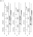
図10は、本発明の他の実施例に係るパワーセーブモードで動作するSTAによるフレーム送受信方法の一例を示す。図10のフレーム送受信方法は、即時SPポールメカニズムによるフレーム送受信方法の一例である。 FIG. 10 shows an example of a frame transmission / reception method by the STA operating in the power save mode according to another embodiment of the present invention. The frame transmission / reception method of FIG. 10 is an example of a frame transmission / reception method based on the immediate SP poll mechanism.
図10を参照すると、ドーズ状態にあるSTAは、TIM要素を受信するためにアウェイク状態に進入する(S1010)。 Referring to FIG. 10, a STA in a doze state enters an awake state to receive a TIM element (S1010).
STAは、TIM要素を受信する(S1020)。TIM要素は、ビーコンフレームに含まれて送信されることができる。端末は、TIM要素を受信すると、TIM要素に含まれている部分仮想ビットマップフィールドのビットマップシーケンスと前記STAのAIDに基づいて自分のためのバッファ可能なフレームがバッファされているかどうかを決定することができる。 The STA receives the TIM element (S1020). The TIM element can be transmitted in a beacon frame. Upon receiving the TIM element, the terminal determines whether a bufferable frame for itself is buffered based on the bitmap sequence of the partial virtual bitmap field included in the TIM element and the AID of the STA. be able to.
バッファ可能なフレームがバッファされていることを確認したSTAは、コンテンション(contention)を介してチャネル接近権限を取得し、SPポールフレームの送信を介してバッファされたフレームの送信をAPに要求することができる(S1030)。 When the STA confirms that the bufferable frame is buffered, the STA obtains the channel access authority through the contention, and requests the AP to transmit the buffered frame through the transmission of the SP poll frame. (S1030).
SPポールフレームを受信したAPは、SIFS以後に少なくとも一つ以上のバッファされたフレームをSTAに送信する(S1041、S1042、S1043)。この場合、APは、ポーリングされたサービス区間中、複数のバッファされたフレームを連続的に送信することができる。 The AP that has received the SP poll frame transmits at least one buffered frame to the STA after SIFS (S1041, S1042, and S1043). In this case, the AP can continuously transmit a plurality of buffered frames during the polled service period.
APとSTAとの間の別途のシグナリングを介して特定ポーリングされたサービス区間が設定されない場合、APがポーリングされたサービス区間中にSTAに送信する最後のバッファされたフレームにはEOSP値が1に設定されることができる。これによって、STAとAPとの間のポーリングされたサービス区間を終了させることができる。 If the specific polled service interval is not set through separate signaling between the AP and the STA, the EOSP value is set to 1 in the last buffered frame transmitted to the STA during the polled service interval. Can be set. As a result, the polled service interval between the STA and the AP can be terminated.
それに対し、APとSTAとの間の別途のシグナリングを介して特定ポーリングされたサービス区間が設定されることができる。そのために、STAが送信するSPポールフレームの持続時間フィールドが適用されることができる。この場合、ポーリングされたサービス区間は、STAがSPポールフレームを送信した時点又はAPがSPポールフレームを受信した時点に開始されることができる。ポーリングされたサービス区間は、開始時点から持続時間フィールドが指示する時間区間中に設定されることができる。APは、ポーリングされたサービス区間の持続時間に合わせてバッファされたフレームを送信することができる。STAは、ポーリングされたサービス区間の持続時間に合わせてバッファされたフレームを受信することができる。 On the other hand, a specific polled service section can be set through separate signaling between the AP and the STA. For this purpose, the duration field of the SP poll frame transmitted by the STA can be applied. In this case, the polled service period can be started when the STA transmits the SP poll frame or when the AP receives the SP poll frame. The polled service period can be set in the time period indicated by the duration field from the start time. The AP can send a buffered frame to match the duration of the polled service interval. The STA can receive a buffered frame according to the duration of the polled service interval.
STAは、ACKフレームをAPに送信することができる(S1050)。STAは、ACKフレームを送信した後、ドーズ状態に進入する(S1060)。ACKフレームは、ポーリングされたサービス区間が満了される時点に送信されることができる。 The STA can transmit an ACK frame to the AP (S1050). After transmitting the ACK frame, the STA enters the doze state (S1060). The ACK frame can be transmitted when the polled service period expires.
図11は、本発明の他の実施例に係るパワーセーブモードで動作するSTAによるフレーム送受信方法の他の一例を示す。図11のフレーム送受信方法は、遅延されたSPポールメカニズムに基づく。 FIG. 11 shows another example of the frame transmission / reception method by the STA operating in the power save mode according to another embodiment of the present invention. The frame transmission / reception method of FIG. 11 is based on a delayed SP poll mechanism.
図11を参照すると、ドーズ状態にあるSTAは、TIM要素を受信するためにアウェイク状態に進入する(S1111)。 Referring to FIG. 11, a STA in a doze state enters an awake state to receive a TIM element (S1111).
STAは、TIM要素を受信する(S1112)。TIM要素は、ビーコンフレームに含まれて送信されることができる。端末は、TIM要素を受信すると、TIM要素に含まれている部分仮想ビットマップフィールドのビットマップシーケンスと前記STAのAIDに基づいて自分のためのバッファ可能なフレームがバッファされているかどうかを決定することができる。 The STA receives the TIM element (S1112). The TIM element can be transmitted in a beacon frame. Upon receiving the TIM element, the terminal determines whether a bufferable frame for itself is buffered based on the bitmap sequence of the partial virtual bitmap field included in the TIM element and the AID of the STA. be able to.
バッファ可能なフレームがバッファされていることを確認したSTAは、コンテンションを介してチャネル接近権限を取得し(S1121)、SPポールフレームの送信を介してバッファされたフレームの送信をAPに要求することができる(S1122)。SPポールフレームの送信によって第1のポーリングされたサービス区間が開始されることができる。 The STA confirming that the bufferable frame is buffered acquires the channel access authority through the contention (S1121), and requests the AP to transmit the buffered frame through the transmission of the SP poll frame. (S1122). The first polled service period can be initiated by transmission of the SP poll frame.
一方、APは、SPポールフレームを受信し、SIFS内にSTAにバッファされたフレームを送信することができない場合がある。この場合、APは、SPポールフレームを受信した後、ACKフレームをSTAに送信する(S1123)。 On the other hand, the AP may not be able to receive the SP poll frame and transmit the frame buffered by the STA in the SIFS. In this case, after receiving the SP poll frame, the AP transmits an ACK frame to the STA (S1123).
送信されたSPポールフレームに対する応答としてACKフレームを受信したSTAは、APがバッファされたフレームを送信することができないことを認知することができる。この場合、SPポールフレームの送信により開始された第1のポーリングされたサービス区間は終了されることができる。STAは、ACKフレームを受信し、ドーズ状態に進入する(S1124)。 The STA that receives the ACK frame in response to the transmitted SP poll frame can recognize that the AP cannot transmit the buffered frame. In this case, the first polled service period started by transmission of the SP poll frame can be terminated. The STA receives the ACK frame and enters the doze state (S1124).
一方、STAは、SPポールフレームのポーリングされたSPインターバルフィールドが指示する時点にアウェイク状態に進入し(S1131)、コンテンションを介してチャネル接近権限を取得する(S1132)。 On the other hand, the STA enters the awake state at the time point indicated by the polled SP interval field of the SP poll frame (S1131), and acquires channel access authority via contention (S1132).
チャネル接近権限を取得したSTAは、SPポールフレームの送信を介してフレームを送信することをAPに要求する(S1133)。SPポールフレームの送信を介して第2のポーリングされたサービス区間が開始される。 The STA that has acquired the channel access authority requests the AP to transmit the frame via the transmission of the SP poll frame (S1133). A second polled service interval is initiated via transmission of the SP poll frame.
一方、APは、S1122ステップで受信したSPポールフレームのポーリングされたSPインターバルフィールドを介して、STAが第2のポーリングされたサービス区間を開始しようとする時点を予め把握することができる。一例として、ポーリングされたSPインターバルフィールドが二つのポーリングされたサービス区間のインターバルを指示する場合、S1122ステップでのSPポールフレームに含まれているポーリングされたSPインターバルフィールドを解釈することで、STAが第2のポーリングされたサービス区間の開始してバッファされたフレームを受信しようとする時点が分かる。他の例として、ポーリングされたSPインターバルフィールドが、既にSPポールフレームを送信したSTAが次のSPポールフレームを送信しようとするインターバルを指示する場合、APは、S1122ステップでのSPポールフレームに含まれているポーリングされたSPインターバルフィールドを解釈することで、STAがSPポールフレームを送信するために動作する時点が分かる。ただし、図11の例示において、ポーリングされたSPインターバルフィールドは、次のSPポールフレームを送信しようとする時点を指示すると仮定した場合のポーリングされたSPインターバルが図示されている。 On the other hand, the AP can grasp in advance the time when the STA intends to start the second polled service interval through the polled SP interval field of the SP poll frame received in step S1122. As an example, if the polled SP interval field indicates the interval of two polled service intervals, the STA interprets the polled SP interval field included in the SP poll frame in step S1122 so that the STA It can be seen at the beginning of the second polled service interval that a buffered frame is to be received. As another example, if the polled SP interval field indicates the interval at which the STA that has already transmitted the SP poll frame attempts to transmit the next SP poll frame, the AP is included in the SP poll frame in step S1122. By interpreting the polled SP interval field, it is possible to know when the STA operates to transmit the SP poll frame. However, in the example of FIG. 11, the polled SP interval field shows the polled SP interval when it is assumed that it indicates the time point at which the next SP poll frame is to be transmitted.
したがって、APは、SPポールフレームを受信し、SIFS後にSTAに送信するバッファされたフレームを予め用意することができる。APは、SPポールフレームを受信し、SIFS後に一つ又はそれ以上のバッファされたフレームを、開始された第2のポーリングされたサービス区間中にSTAに送信することができる(S1141、S1142、S1143)。 Therefore, the AP can prepare the buffered frame to receive the SP poll frame and transmit to the STA after SIFS in advance. The AP can receive the SP poll frame and send one or more buffered frames after SIFS to the STA during the second polled service period initiated (S1141, S1142, S1143). ).
SPポールフレームの送信(S1133)により開始された第2のポーリングされたサービス区間の持続時間は、図10を参照して前述したポーリングされた区間の持続時間のように特定されることができる。即ち、ポーリングされた持続時間は、APが‘1’に設定されたEOSPフィールドを含むバッファされたフレームを送信することによって終了されることができる。または、第2のポーリングされた持続時間は、STAがS1133ステップで送信したSPポールフレームの持続時間フィールドが指示する持続時間により特定されることができる。 The duration of the second polled service period started by transmitting the SP poll frame (S1133) may be specified as the duration of the polled period described above with reference to FIG. That is, the polled duration can be terminated by sending a buffered frame including an EOSP field with the AP set to '1'. Alternatively, the second polled duration can be specified by the duration indicated by the duration field of the SP poll frame transmitted by the STA in step S1133.
STAは、APから少なくとも一つ以上のフレームを受信し、これに対する応答としてACKフレームを送信する(S1144)。STAが送信するACKフレームは、少なくとも一つ以上のバッファされたフレームに対する受信確認応答であり、ブロックACKであってもよい。STAは、ACKフレームを送信した後、ドーズ状態に進入することができる(S1150)。 The STA receives at least one frame from the AP and transmits an ACK frame as a response thereto (S1144). The ACK frame transmitted by the STA is an acknowledgment for at least one buffered frame, and may be a block ACK. After transmitting the ACK frame, the STA can enter the doze state (S1150).
図11において、第2のポーリングされたサービス区間は、STAのACKフレームの送信以後に終了されると図示しているが、第2のポーリングされたサービス区間は、STAがACKフレームを送信する直前に終了されることができる。即ち、STAは、第2のポーリングされたサービス区間が終了されると、ACKフレームをAPに送信するように設定されることもできる。 In FIG. 11, the second polled service interval is illustrated as being terminated after the transmission of the STA's ACK frame, but the second polled service interval is immediately before the STA transmits the ACK frame. Can be terminated. That is, the STA may be set to transmit an ACK frame to the AP when the second polled service period ends.
図11によるフレーム送受信方法において、第1のポーリングされたサービス区間中、APは、STAのSPポールフレームに対する応答としてACKフレームを送信する。したがって、第1のポーリングされたサービス区間中には、遅延されたSPポールに基づくフレーム送受信方法が実行される。第2のポーリングされたサービス区間中、APは、STAのSPポールフレームに対する応答として少なくとも一つのバッファされたフレームを送信する。したがって、第2のポーリングされたサービス区間中には、即時SPポールに基づくフレーム送受信方法が実行される。 In the frame transmission / reception method according to FIG. 11, the AP transmits an ACK frame in response to the STA's SP poll frame during the first polled service interval. Therefore, a frame transmission / reception method based on the delayed SP poll is executed during the first polled service period. During the second polled service interval, the AP transmits at least one buffered frame in response to the STA's SP poll frame. Therefore, a frame transmission / reception method based on the immediate SP poll is executed during the second polled service period.
図9乃至図11を参照して詳述したフレーム送受信方法によると、STAは、SPポールフレームにより設定されたサービス区間中にアウェイク状態を維持し、APからフレームを受信することができる。これによって、STAは、頻繁なアウェイク状態/ドーズ状態の切り替え動作をしなくても、サービス区間中、少なくとも一つ以上のAPからフレームを受信することができる。これによって、データ送受信のためのSTAの動作の効率化が企図されることができる。 According to the frame transmission / reception method described in detail with reference to FIGS. 9 to 11, the STA can maintain the awake state during the service interval set by the SP poll frame and receive the frame from the AP. Accordingly, the STA can receive a frame from at least one AP during the service period without frequently switching the awake state / doze state. Accordingly, it is possible to increase the efficiency of the operation of the STA for data transmission / reception.
以下、パワーセーブモードで動作するSTAがAPから少なくとも一つ以上のフレームを受信することができる区間であるサービス区間をスケジューリングする一般的な方法に対して詳述する。 Hereinafter, a general method for scheduling a service period, which is a period in which the STA operating in the power save mode can receive at least one frame from the AP, will be described in detail.
APとSTAとの間のデータを送受信するために、AP又はSTAは、サービス区間を予 めスケジューリングすることができる。前述した図10及び図11を参照して持続時間フィールド及びポーリングされたSPインターバルフィールドを含むSPポールフレームに基づくポーリングによりポーリングされたサービス区間とポーリングされたSPインターバルが設定されることと違って、サービス区間のスケジューリングは、AP及びSTAがデータを送受信する以前に相互間シグナリングを介して複数のサービス区間と二つのサービス区間との間のインターバルを予め設定することによって、以後サービス区間中にAPとSTAとの間のデータ送受信が行われることができる。 In order to transmit and receive data between the AP and the STA, the AP or the STA can schedule the service period in advance. Unlike the case where the polled service interval and the polled SP interval are set by polling based on the SP poll frame including the duration field and the polled SP interval field with reference to FIGS. 10 and 11 described above, Service segment scheduling is performed by setting an interval between a plurality of service segments and two service segments in advance through inter-signaling before the AP and the STA transmit and receive data. Data can be transmitted to and received from the STA.
図10及び図11を参照して説明したデータ送受信方法において、図面上にはSPポールフレームの送信後からサービス区間が開始されると図示されているが、ポーリングされたサービス区間は、STAがSPポールフレームを送信するためにアウェイク状態に進入する時点から開始されると解釈されても関係ない。ただし、この場合にも、ポーリングされたサービス区間の持続時間は、SPポールフレームの持続時間フィールドの設定値又はAP及び/又はSTAのACKフレームの送信時点により決定されることができる。このような方式によりサービス区間が解釈される場合、ポーリングされたSPインターバルは、二つのポーリングされたサービス区間のインターバルであると解釈されることができる。 In the data transmission / reception method described with reference to FIG. 10 and FIG. 11, the drawing shows that the service section starts after the transmission of the SP poll frame. It does not matter if it is interpreted as starting from the point of entering the awake state to transmit a poll frame. However, also in this case, the duration of the polled service period can be determined by the setting value of the duration field of the SP poll frame or the transmission time of the AP and / or STA ACK frame. When the service interval is interpreted in such a manner, the polled SP interval can be interpreted as an interval between two polled service intervals.
STAのサービス区間を予めスケジューリングすることで、APは、STAのスケジューリングされたサービス区間関連情報を事前に把握し、STAに送信するデータを用意することができる。STAは、スケジューリングされたサービス区間に合わせてアウェイク状態とドーズ状態とを切り替えて動作することができる。即ち、サービス区間が開始される時点にアウェイク状態に進入することによってデータ送受信が可能な状態を維持することができ、サービス区間が終了される時点にドーズ状態に進入することによって不要に消耗されるパワーをセーブすることができる。サービス区間を予めスケジューリングするために、AP及びSTAは、サービス区間のスケジューリングのためのスケジューリング情報を事前に共有する必要がある。 By scheduling the service section of the STA in advance, the AP can grasp in advance the STA scheduled service section related information and prepare data to be transmitted to the STA. The STA can operate by switching between the awake state and the doze state according to the scheduled service period. That is, by entering the awake state when the service section starts, it is possible to maintain a state where data can be transmitted and received, and when the service section ends, it is consumed unnecessarily by entering the doze state. You can save power. In order to schedule service sections in advance, APs and STAs need to share scheduling information for scheduling service sections in advance.
サービス区間のスケジューリングは、サービス区間の持続時間を指示する情報とサービス区間のインターバルを指示することによって行われることができ、このような情報を介して構成されたスケジューリングされたサービス区間は、図12を参照することができる。 Service segment scheduling can be performed by indicating information indicating the duration of the service interval and the interval of the service interval. The scheduled service interval configured through such information is shown in FIG. Can be referred to.
図12は、本発明の実施例に係るスケジューリングされたサービス区間の例示を示す。 FIG. 12 illustrates an example of a scheduled service period according to an embodiment of the present invention.
図12を参照すると、スケジューリングされたサービス区間は、スケジューリングされたサービス区間の開始点(start point of scheduled service periods)、サービス区間の持続時間(service period duration)及びサービス区間インターバル(service period interval)で表現されることができる。 Referring to FIG. 12, a scheduled service period includes a start point of scheduled service period, a service period duration, and a service period interval. Can be expressed.
図12の副図面(a)及び副図面(b)において、サービス区間の持続時間は、AP及び/又はSTAがチャネルに接近してデータを送受信することができる持続時間を意味する。一方、各副図面において、サービス区間インターバルは、各々異なる時間インターバルを指示すると解釈されることができる。副図面(a)において、サービス区間インターバルは、以前サービス区間の終了時点と以後サービス区間の開始時点とのインターバルを意味する。副図面(b)において、サービス区間インターバルは、以前サービス区間の開始時点と以後サービス区間の開始時点とのインターバルを意味する。 In the sub-drawing (a) and sub-drawing (b) of FIG. 12, the duration of the service period means a duration in which the AP and / or STA can transmit and receive data close to the channel. On the other hand, in each sub-drawing, the service interval interval can be interpreted to indicate a different time interval. In the sub-drawing (a), the service section interval means an interval between the end time of the previous service section and the start time of the subsequent service section. In the sub drawing (b), the service section interval means an interval between the start time of the previous service section and the start time of the subsequent service section.
図12の副図面(a)と副図面(b)は、同じにサービス区間がスケジューリングされていることが分かる。したがって、STAは、サービス区間が開始される時点にアウェイク状態に進入することによってデータ送受信が可能な状態を維持することができ、サービス区間が終了される時点にドーズ状態に進入することができる。 It can be seen that the sub-drawings (a) and (b) of FIG. Therefore, the STA can maintain a state in which data can be transmitted and received by entering the awake state at the time when the service section is started, and can enter the doze state when the service section is ended.
一方、前記のようなサービス区間をスケジューリングするために、APとSTAとの間のサービス区間をスケジューリングするためにサービス区間を設定するステップの実行が必要である。これはスケジューリングされたサービス区間が開始される時点、サービス区間の持続時間及びサービス区間のインターバルに対する情報をAP及びSTAが共有して実行されることができる。 Meanwhile, in order to schedule the service interval as described above, it is necessary to execute a step of setting the service interval in order to schedule the service interval between the AP and the STA. This may be performed when the scheduled service period is started and the AP and the STA share information on the service period duration and the service period interval.
全体スケジューリングされたサービス区間の開始時点を指示することは、APにより指示され、又はSTAにより指示されることができる。APにより開始時点を指示することは、特定フレームの送信を介して実行されることができる。前記特定フレームは、ビーコンフレームのように既存に存在するフレームであってもよく、スケジューリングされたサービス区間の開始を指示することと関連して新たに定義されるフレームであってもよい。以下、スケジューリングされたサービス区間が開始されることを指示するためのフレームを通称してスケジューリングされたサービス区間開始要求フレーム(scheduled SP start request frame)という。スケジューリングされたサービス区間開始要求フレームを受信したSTAは、これに対する応答としてACKフレーム又はナルフレーム(Null frame)をAPに送信することができる。以下、スケジューリングされたサービス区間開始要求に対する応答として送信されることができるACKフレーム及びナルフレームを通称してスケジューリングされたサービス区間開始応答フレームという。 Indicating the start time of the overall scheduled service interval may be instructed by the AP or by the STA. Indicating the start time by the AP can be performed via transmission of a specific frame. The specific frame may be an existing frame such as a beacon frame, or may be a newly defined frame associated with instructing the start of a scheduled service period. Hereinafter, a scheduled service section start request frame (scheduled SP start request frame) will be referred to as a frame for instructing that the scheduled service section is started. The STA that has received the scheduled service interval start request frame can transmit an ACK frame or a null frame (Null frame) to the AP as a response thereto. Hereinafter, an ACK frame and a null frame that can be transmitted as a response to the scheduled service interval start request are referred to as a scheduled service interval start response frame.
一方、STAがスケジューリングされたサービス区間が開始される時点を指示することができる。STAは、スケジューリングされたサービス区間が開始される時点を指示するために、スケジューリングされたサービス区間開始要求フレームをAPに送信することができる。スケジューリングされたサービス区間開始要求フレームは、PSポールフレームのように既存に存在するフレームであってもよく、前述したSPポールフレームであってもよい。スケジューリングされたサービス区間開始要求フレームをSTAから受信したAPは、これに対する応答としてスケジューリングされたサービス区間開始応答フレームを送信することができ、これはACKフレーム又はナルフレームである。 On the other hand, it is possible to indicate when the service section scheduled for the STA is started. The STA can send a scheduled service period start request frame to the AP to indicate when the scheduled service period starts. The scheduled service interval start request frame may be an existing frame such as a PS poll frame, or the SP poll frame described above. The AP that has received the scheduled service interval start request frame from the STA can transmit a scheduled service interval start response frame as a response thereto, which is an ACK frame or a null frame.
前述したスケジューリングされたサービス区間の開始を指示する方法は、図13を参照することができる。 The method for instructing the start of the scheduled service interval described above can be referred to FIG.
図13は、本発明の実施例に係るスケジューリングされたサービス区間の開始を指示する方法の例示を示す。 FIG. 13 shows an example of a method for indicating the start of a scheduled service interval according to an embodiment of the present invention.
図13の副図面(a)は、APによりサービス区間の開始が指示される例示を示す。APは、スケジューリングされたサービス区間が開始されることを指示するスケジューリングされたサービス区間開始要求フレームをSTAに送信する(S1310a)。前記スケジューリングされたサービス区間開始要求フレームは、ビーコンフレーム及び/又は前記要求のために新たに定義されるフレームであってもよい。 The sub-drawing (a) of FIG. 13 shows an example in which the start of the service section is instructed by the AP. The AP transmits to the STA a scheduled service section start request frame instructing that the scheduled service section is started (S1310a). The scheduled service period start request frame may be a beacon frame and / or a newly defined frame for the request.
前記スケジューリングされたサービス区間開始要求フレームに対する応答として、STAは、APにスケジューリングされたサービス区間開始応答フレームを送信する(S1320a)。前記スケジューリングされたサービス区間開始応答フレームは、ACKフレーム及び/又はナルフレームである。 As a response to the scheduled service interval start request frame, the STA transmits a service interval start response frame scheduled to the AP (S1320a). The scheduled service period start response frame is an ACK frame and / or a null frame.
前記例示によると、スケジューリングされたサービス区間は、APの要求に対するSTAの応答の以後に開始されることが分かる。 According to the above example, it can be seen that the scheduled service period starts after the STA response to the AP request.
図13の副図面(b)は、STAによりサービス区間の開始が指示される例示を示す。STAは、スケジューリングされたサービス区間が開始されることを指示するスケジューリングされたサービス区間開始要求フレームをAPに送信することができる(S1310b)。前記スケジューリングされたサービス区間開始要求フレームは、PSポールフレーム及び/又はSPポールフレームである。 The sub-drawing (b) of FIG. 13 shows an example where the start of the service section is instructed by the STA. The STA can transmit a scheduled service period start request frame instructing that the scheduled service period is started to the AP (S1310b). The scheduled service interval start request frame is a PS poll frame and / or an SP poll frame.
前記スケジューリングされたサービス区間開始要求フレームに対する応答として、APは、STAにスケジューリングされたサービス区間開始応答フレームを送信する(S1320b)。前記スケジューリングされたサービス区間開始応答フレームは、ACKフレーム及び/又はナルフレームである。 As a response to the scheduled service interval start request frame, the AP transmits a service interval start response frame scheduled to the STA (S1320b). The scheduled service period start response frame is an ACK frame and / or a null frame.
前記例示によると、スケジューリングされたサービス区間は、STAのスケジューリングされたサービス区間開始要求フレームの送信の以後に開始されることが分かる。 According to the above example, it can be seen that the scheduled service period starts after transmission of the STA's scheduled service period start request frame.
一方、図13の例示において、サービス区間インターバルは、以前サービス区間の終了時点と以後サービス区間の開始時点との間のインターバルであると図示されているが、これに限定されるものではない。サービス区間インターバルは、二つのサービス区間の開始時点間のインターバルで具現されることができる。 On the other hand, in the example of FIG. 13, the service interval is illustrated as an interval between the end time of the previous service interval and the start time of the subsequent service interval, but is not limited thereto. The service interval may be implemented as an interval between the start times of two service intervals.
前述したように開始されたスケジューリングされたサービス区間のスケジューリング情報は、サービス区間の持続時間及びサービス区間インターバルで具現されることができ、このような情報は、STA及び/又はAPにより決定され、互いに共有されることができる。そのために、サービス区間の持続時間情報及びサービス区間インターバル情報は、STAが決定してAPに知らせ、又はAPが決定してSTAに知らせることができる。前記サービス区間の持続時間情報及び前記サービス区間インターバル情報は、スケジューリングされたサービス区間開始要求フレームに含まれて送信され、又はスケジューリングされたサービス区間開始応答フレームに含まれて送信されることができる。この場合、前記サービス区間の持続時間関連情報は、別途のサービス区間の持続時間フィールドで具現され、又は前記サービス区間開始要求フレーム及び/又は前記サービス区間開始応答フレームの持続時間フィールドで具現されることができる。前記サービス区間インターバル関連情報は、別途のサービス区間インターバルフィールドで具現され、前記サービス区間開始要求フレーム及び/又は前記サービス区間開始応答フレームに含まれることができる。 The scheduling information of the scheduled service period started as described above may be implemented by the duration of the service period and the service period interval, which is determined by the STA and / or the AP, Can be shared. Therefore, the service section duration information and the service section interval information can be determined by the STA and notified to the AP, or the AP can be determined and notified to the STA. The service period duration information and the service period interval information may be transmitted in a scheduled service period start request frame or may be transmitted in a scheduled service period start response frame. In this case, the service period duration related information may be implemented in a separate service section duration field, or in the service section start request frame and / or the service section start response frame duration field. Can do. The service interval interval related information may be implemented in a separate service interval interval field and may be included in the service interval start request frame and / or the service interval start response frame.
一方、前記サービス区間の持続時間関連情報及び前記サービス区間インターバル関連情報は、スケジューリングされたサービス区間情報要素で具現され、結合応答フレーム又はプローブ応答フレームに含まれることができる。スケジューリングされたサービス区間開始要求フレームやスケジューリングされたサービス区間開始応答フレームにサービス区間の持続時間及びサービス区間インターバルに対する明示的な指示情報がない場合、前記スケジューリングされたサービス区間情報要素に含まれている情報によりサービス区間の持続時間及びサービス区間インターバルが設定されることができる。 Meanwhile, the service interval duration related information and the service interval interval related information may be implemented by a scheduled service interval information element and included in a combined response frame or a probe response frame. If there is no explicit indication information for the duration of the service section and the service section interval in the scheduled service section start request frame or the scheduled service section start response frame, it is included in the scheduled service section information element According to the information, the duration of the service interval and the service interval can be set.
前記スケジューリングされたサービス区間情報要素のフォーマットは、図14を参照することができる。 The format of the scheduled service period information element can be referred to FIG.
図14は、本発明の実施例に係るスケジューリングされたサービス区間情報要素のフォーマットを示すブロック図である。 FIG. 14 is a block diagram illustrating a format of a scheduled service interval information element according to an embodiment of the present invention.
図14を参照すると、スケジューリングされたサービス区間情報要素1400は、要素IDフィールド1410、長さフィールド1420、サービス区間持続時間フィールド1430及びサービス区間インターバルフィールド1440を含む。
Referring to FIG. 14, the scheduled service
要素IDフィールド1410は、該当情報要素がスケジューリングされたサービス区間情報要素であることを指示するように設定されることができる。
The
長さフィールド1420は、サービス区間の持続時間フィールド1430及びサービス区間インターバルフィールド1440を構成するビットシーケンス全体の長さを指示するように設定されることができる。
The
サービス区間の持続時間フィールド1430は、前記サービス区間の持続時間関連情報を含み、サービス区間インターバルフィールド1440は、サービス区間インターバル関連情報を含むように設定されることができる。
The service
前記のようにスケジューリングされたサービス区間中、各サービス区間が終了される時点をAP及びSTAが共有する必要がある。各サービス区間は、明示的なシグナリングがない場合、各サービス区間の持続時間が満了されることによって終了される。一方、各サービス区間は、持続時間満了前にAP及び/又はSTAによる明示的なシグナリングによって終了されることができる。 Among the service intervals scheduled as described above, the AP and the STA need to share the time point at which each service interval ends. Each service interval is terminated by the expiration of the duration of each service interval in the absence of explicit signaling. Meanwhile, each service period can be terminated by explicit signaling by the AP and / or STA before the duration expires.
図15は、本発明の実施例に係るAPによりサービス区間を終了させる方法の例示を示す。 FIG. 15 illustrates an example of a method for terminating a service interval by an AP according to an embodiment of the present invention.
図15の副図面(a)を参照すると、サービス区間中に少なくとも一つのデータフレームを送信するAPは、サービス区間を終了させようとする場合、最後に送信するフレームのEOSPフィールドを‘1’に設定して送信することができる(S1510)。この場合、実際サービス区間の終了時点は、APにより最後に送信されたフレーム、即ち、‘1’に設定されたEOSPフィールドを含むデータフレームに対する応答としてSTAからACKフレームが送信により決定されることができる。 Referring to the sub-drawing (a) of FIG. 15, when an AP that transmits at least one data frame during a service interval tries to end the service interval, the EOSP field of the frame to be transmitted last is set to '1'. It can be set and transmitted (S1510). In this case, the end point of the actual service period is determined by transmission of an ACK frame from the STA as a response to the frame transmitted last by the AP, that is, the data frame including the EOSP field set to '1'. it can.
図15の副図面(b)を参照すると、サービス区間中に少なくとも一つのデータフレームを送信するAPは、サービス区間を終了させようとする場合、CF−終了フレーム(CF−End frame)を送信することができる(S1520)。前記CF−終了フレームは、CFP(Contention Free Period)又はTXOP(Transmission Opportunity)のようにチャネルに接近してフレームを送信することができる権限を有するAP及び/又はSTAが該当接近権限をリリースするために送信するフレームである。したがって、CF−終了フレームをサービス区間にも適用してサービス区間を終了させようとするAPがCF−終了フレームを送信するように具現されることができる。実際サービス区間が終了される時点は、CF−終了フレームの送信により決定されることができる。 Referring to the sub-drawing (b) of FIG. 15, an AP that transmits at least one data frame during a service interval transmits a CF-end frame when the service interval is to be ended. (S1520). The CF-end frame is used for releasing APs and / or STAs having authority to transmit a frame close to a channel, such as CFP (Contention Free Period) or TXOP (Transmission Opportunity). Is a frame to be transmitted to Accordingly, an AP that applies the CF-end frame to the service period and ends the service period may be implemented to transmit the CF-end frame. The point in time when the actual service section is terminated can be determined by transmitting a CF-end frame.
図16は、本発明の実施例に係るSTAによりサービス区間を終了させる方法の例示を示す。 FIG. 16 illustrates an example of a method for terminating a service interval by an STA according to an embodiment of the present invention.
図16の副図面(a)を参照すると、サービス区間中に少なくとも一つのデータフレームを受信するSTAは、サービス区間を終了させようとする場合、受信されたデータフレームに対するACKフレームを送信後、CF−終了フレームを送信することができる(S1610)。実際サービス区間の終了時点は、STAによるCF−終了フレームの送信により決定されることができる。 Referring to the sub-drawing (a) of FIG. 16, when an STA that receives at least one data frame during a service interval transmits an ACK frame for the received data frame, -An end frame can be transmitted (S1610). The end point of the actual service period can be determined by transmitting a CF-end frame by the STA.
図16の副図面(b)を参照すると、サービス区間中に少なくとも一つのデータフレームを受信するSTAは、サービス区間を終了させようとする場合、ACKフレームにサービス区間が終了されることを指示する情報を含ませて送信することができる(S1620)。実際サービス区間の終了時点は、前記サービス区間の終了を指示する情報が含まれているACKフレームの送信により決定されることができる。 Referring to FIG. 16B, the STA that receives at least one data frame during the service period instructs the ACK frame to end the service period when the STA intends to end the service period. Information can be included and transmitted (S1620). The end point of the actual service period can be determined by transmitting an ACK frame including information indicating the end of the service period.
図16の副図面(c)を参照すると、サービス区間中に少なくとも一つのデータフレームを受信するSTAは、サービス区間を終了させようとする場合、ACK+SP終了フレームを送信することができる(S1630)。ACK+SP終了フレームは、データフレームに対する受信確認応答機能とサービス区間の終了を指示する機能を備える新たに定義したフレームである。実際サービス区間の終了時点は、ACK+SP終了フレームの送信により決定されることができる。 Referring to the sub drawing (c) of FIG. 16, a STA that receives at least one data frame during a service period may transmit an ACK + SP end frame when the service period is to be terminated (S1630). The ACK + SP end frame is a newly defined frame having a reception confirmation response function for the data frame and a function for instructing the end of the service section. The end point of the actual service period can be determined by transmitting an ACK + SP end frame.
一方、AP及び/又はSTAはスケジューリングされた全てのサービス区間を終了したい場合、これを相互間にシグナリングすることができる。AP及び/又はSTAは、全体スケジューリングされたSPの終了を明示的に指示することができる。 On the other hand, if the AP and / or STA wants to terminate all scheduled service intervals, it can signal this to each other. The AP and / or STA can explicitly indicate the end of the overall scheduled SP.
図17は、本発明の実施例に係るAPによる全体スケジューリングされたサービス区間を終了させる方法の例示を示す。 FIG. 17 illustrates an example of a method for terminating an overall scheduled service interval by an AP according to an embodiment of the present invention.
図17の副図面(a)を参照すると、APは、データフレームのMD(More Data)フィールドに基づいてスケジューリングされた全体サービス区間を終了させることができる。前記MDフィールドは、送信者が送信するデータがさらにあるかどうかを指示する。MDフィールドが‘0’に設定されている場合、該当フィールドは、これ以上送信するデータが無いことを指示する。MDフィールドが‘1’に設定されている場合、該当フィールドは、さらに送信するデータが存在することを指示する。したがって、APは‘0’に設定されたMDフィールドを含むデータフレームを送信することによってスケジューリングされた全体サービス区間を終了させることができる(S1710)。一方、スケジューリングされた全体サービス区間が終了される時点は、‘0’に設定されたMDフィールドを含むデータフレームが送信され、前記データフレームに対する応答として送信されるACKフレームにより決定されることができる。 Referring to the sub-drawing (a) of FIG. 17, the AP can terminate the entire service period scheduled based on the MD (More Data) field of the data frame. The MD field indicates whether there is more data to be transmitted by the sender. When the MD field is set to “0”, the corresponding field indicates that there is no more data to be transmitted. When the MD field is set to “1”, the corresponding field indicates that there is further data to be transmitted. Therefore, the AP can terminate the scheduled entire service period by transmitting a data frame including the MD field set to '0' (S1710). On the other hand, the time point at which the scheduled overall service period ends can be determined by an ACK frame transmitted as a response to the data frame, in which a data frame including an MD field set to '0' is transmitted. .
図17の副図面(b)を参照すると、APは、スケジューリングされた全体サービス区間を終了することを指示するフレームをSTAに送信することで、スケジューリングされた全体サービス区間を終了させることができる(S1720)。前記フレームは、スケジューリングされた全体サービスを終了させるために新たに定義されるスケジューリングされたサービス区間終了フレーム(Scheduled SP end frame)であってもよい。スケジューリングされた全体サービス区間が終了される時点は、サービス区間終了フレームの送信に対するSTAの応答(例えば、ACK)により決定されることができる。 Referring to the sub-drawing (b) of FIG. 17, the AP can end the scheduled overall service section by transmitting a frame instructing the end of the scheduled overall service period to the STA (see FIG. 17). S1720). The frame may be a scheduled service interval end frame (Scheduled SP end frame) newly defined to end the scheduled overall service. The time point at which the scheduled entire service period is ended may be determined by a response of the STA (for example, ACK) to the transmission of the service period end frame.
図18は、本発明の実施例に係るSTAによる全体スケジューリングされたサービス区間を終了させる方法の例示を示す。 FIG. 18 illustrates an example of a method for terminating an overall scheduled service interval by an STA according to an embodiment of the present invention.
図18の副図面(a)を参照すると、スケジューリングされた全体サービス区間を終了させるために、前述したMDフィールドを‘0’に設定し、前記MDフィールドを含むACKフレームをAPに送信することができる(S1810)。スケジューリングされた全体サービス区間が終了される時点は、‘0’に設定されたMDフィールドを含むACKフレームの送信により決定されることができる。 Referring to the sub-drawing (a) of FIG. 18, in order to end the scheduled overall service period, the MD field described above is set to '0' and an ACK frame including the MD field is transmitted to the AP. Yes (S1810). The time point at which the scheduled overall service period ends can be determined by transmitting an ACK frame including an MD field set to '0'.
図18の副図面(b)を参照すると、STAは、スケジューリングされた全体サービス区間を終了することを指示するフレームをAPに送信することによって、スケジューリングされた全体サービス区間を終了させることができる(S1820)。前記フレームは、前述したスケジューリングされたサービス区間終了フレームであってもよい。スケジューリングされた全体サービス区間が終了される時点は、サービス区間終了フレームの送信により決定されることができる。 Referring to the sub-drawing (b) of FIG. 18, the STA can end the scheduled overall service interval by transmitting a frame instructing the AP to end the scheduled overall service interval. S1820). The frame may be the scheduled service interval end frame described above. The time point at which the scheduled entire service period ends can be determined by transmitting a service period end frame.
以上、図12乃至図18を参照してサービス区間をスケジューリングする方法に対して詳述した。前述したスケジューリング方法の実施例において、各々のサービス区間は、個別的な指示により開始されずに、スケジューリングされた全体サービス区間と関連したサービス区間の持続時間及びサービス区間インターバルに対する情報により開始された。また、全体サービス区間の開始時点は、AP及び/又はSTAの明示的なシグナリングにより開始された。 The method for scheduling service intervals has been described in detail above with reference to FIGS. In the above-described scheduling method embodiment, each service period is not started by an individual instruction, but is started by information on the duration of the service period and the service period interval associated with the scheduled overall service period. In addition, the start point of the entire service interval is started by explicit signaling of the AP and / or STA.
一方、各々のサービス区間は、個別的な指示によりスケジューリングされることに基づくサービス区間個別スケジューリング方法も提案されることができる。一方、サービス区間個別スケジューリング方法は、具体的に、図9乃至図11を参照して説明したSP ポールフレームに基づくデータ送受信方法におけるサービス区間のように実行されることができる。ただし、以下では一般的なサービス区間個別スケジューリング方法に対して説明する。 Meanwhile, a service segment individual scheduling method based on scheduling each service segment according to an individual instruction may be proposed. Meanwhile, the service interval individual scheduling method can be executed as a service interval in the data transmission / reception method based on the SP poll frame described with reference to FIGS. 9 to 11. However, a general service interval individual scheduling method will be described below.
図19は、本発明の実施例に係る個別スケジューリングされたサービス区間の例示を示す。 FIG. 19 illustrates an example of an individually scheduled service interval according to an embodiment of the present invention.
図19を参照すると、スケジューリングされたサービス区間は、全体スケジューリングされたサービス区間の開始点、サービス区間の持続時間及びサービス区間インターバルで表現されることができる。ただし、図12乃至18を参照して前述したスケジューリング方法と違って、各サービス区間は、個別的にスケジューリングされる。 Referring to FIG. 19, a scheduled service period can be represented by a start point of the overall scheduled service period, a service period duration, and a service period interval. However, unlike the scheduling method described above with reference to FIGS. 12 to 18, each service section is scheduled individually.
STAは、各サービス区間の開始点にSPポールフレームを送信する。STAは、SPポールフレームを送信することによって各サービス区間が開始されたことを知らせ、データを送信することをAPに要求することができる。 The STA transmits an SP poll frame to the start point of each service section. The STA can inform the AP to transmit data by informing that each service period has started by transmitting an SP poll frame.
一方、全体スケジューリングされたサービス区間の開始点に対する情報は、AP及びSTAが共有できる。図12乃至図18を参照して前述したスケジューリング方法のように、全体スケジューリングされたサービス区間の開始点は、APにより指示され、又はSTAにより指示されることができる。スケジューリングされたサービス区間が開始されることは、AP及び/又はSTAによりスケジューリングされたサービス区間開始要求フレームが送信され、これに対する応答としてSTA及び/又はAPによりスケジューリングされたサービス区間開始応答フレームが送信されることにより開示されることができる。 On the other hand, information on the start point of the service section that has been scheduled overall can be shared by the AP and the STA. As in the scheduling method described above with reference to FIGS. 12 to 18, the start point of the overall scheduled service period may be indicated by the AP or may be indicated by the STA. When the scheduled service period is started, a service period start request frame scheduled by the AP and / or STA is transmitted, and a service period start response frame scheduled by the STA and / or AP is transmitted as a response thereto. Can be disclosed.
APにより要求される場合、全体スケジューリングされたサービス区間の開始時点は、STAの応答により開始されることができる。STAにより要求される場合、全体スケジューリングされたサービス区間の開始時点は、STAの要求により開始されることができる。 When requested by the AP, the start time of the overall scheduled service period can be started by the response of the STA. When requested by the STA, the start point of the overall scheduled service period can be started by the request of the STA.
一方、図19の例示において、サービス区間インターバルは、以前サービス区間の終了時点と以後サービス区間の開始時点との間のインターバルであると図示されているが、これに限定されるものではない。サービス区間インターバルは、二つのサービス区間の開始時点間のインターバルで具現されることができる。 On the other hand, in the illustration of FIG. 19, the service interval is illustrated as an interval between the end time of the previous service interval and the start time of the subsequent service interval, but is not limited thereto. The service interval may be implemented as an interval between the start times of two service intervals.
各サービス区間のスケジューリング情報は、サービス区間の持続時間及びサービス区間インターバルで具現されることができる。一方、このような情報は、STA及び/又はAPにより決定され、互いに共有されることができる。 Scheduling information for each service interval may be implemented with a service interval duration and a service interval interval. On the other hand, such information can be determined by STAs and / or APs and shared with each other.
STAが各サービス区間のスケジューリング情報を決定する場合、サービス区間の持続時間は、現在サービス区間内にSTAにより送信されたSPポールフレームの持続時間フィールドにより決定されることができる。また、サービス区間のインターバルは、現在サービス区間以前にSTAにより送信されたSPポールフレームに含まれているポーリングされたSPインターバルフィールドにより決定されることができる。現在サービス区間は、STAによりSPポールフレームが送信される時からSPポールフレームの持続時間フィールドが指示する時間中維持されることができる。次のサービス区間は、SPポールフレームのポーリングされたSPインターバルフィールドにより決定される時点に開始されることができる。 If the STA determines the scheduling information for each service period, the duration of the service period may be determined by the duration field of the SP poll frame transmitted by the STA in the current service period. Also, the service interval may be determined by a polled SP interval field included in an SP poll frame transmitted by the STA before the current service interval. The current service period can be maintained for the time indicated by the duration field of the SP poll frame from when the SP poll frame is transmitted by the STA. The next service interval may be started at a time determined by the polled SP interval field of the SP poll frame.
APによりサービス区間のスケジューリング情報が決定される場合、サービス区間の持続時間は、現在サービス区間内にSTAにより送信されたSPポールフレームに対する応答により又はAPによる別途のシグナリングのために送信されたスケジューリングされたサービス区間情報要素のサービス区間の持続時間フィールドにより決定されることができる。また、サービス区間のインターバルは、現在サービス区間以前にAPにより送信されたサービス区間情報要素のサービス区間インターバルフィールドにより送信されることができる。即ち、既に開始されたサービス区間の場合、APによりサービス区間情報要素が送信される時から、サービス区間の持続時間フィールドが指示する時間中サービス区間が持続することができる。また、次のサービス区間は、サービス区間情報要素のサービス区間インターバルフィールドにより決定された時点に開始されることができる。一方、前記サービス区間情報要素は、新たに定義される特定フレーム、STAにより送信されたSPポールフレームに対する応答として送信されるフレーム(例えば、ACKフレーム)又はサービス区間中に送信されるデータフレームに含まれて送信されることができる。 If the scheduling information of the service section is determined by the AP, the duration of the service section is scheduled according to a response to the SP poll frame transmitted by the STA in the current service section or for additional signaling by the AP. The service duration information field can be determined by the service duration duration field. The service interval may be transmitted in the service interval field of the service interval information element transmitted by the AP before the current service interval. That is, in the case of a service period that has already been started, the service period can be sustained for the time indicated by the duration field of the service period from when the service period information element is transmitted by the AP. Also, the next service interval may be started at a time determined by the service interval interval field of the service interval information element. Meanwhile, the service section information element is included in a newly defined specific frame, a frame transmitted as a response to the SP poll frame transmitted by the STA (for example, an ACK frame), or a data frame transmitted during the service section. Can be sent.
前記のように、個別的にスケジューリングされた各サービス区間は、明示的なシグナリングがない場合、各サービス区間の持続時間が満了されることによって終了される。一方、各サービス区間は、持続時間の満了前にAP及び/又はSTAによる明示的なシグナリングによって終了されることができる。 As described above, each individually scheduled service period is terminated when the duration of each service period expires in the absence of explicit signaling. Meanwhile, each service interval can be terminated by explicit signaling by the AP and / or STA before the duration expires.
図20は、本発明の実施例に係るAPにより個別スケジューリングされたサービス区間を終了させる方法の例示を示す。 FIG. 20 illustrates an example of a method for terminating a service interval individually scheduled by an AP according to an embodiment of the present invention.
図20の副図面(a)を参照すると、サービス区間中に少なくとも一つのデータフレームを送信するAPは、サービス区間を終了させようとする場合、最後に送信するフレームのEOSPフィールドを‘1’に設定して送信できる(S2010)。この場合、実際サービス区間の終了時点は、APにより最後に送信されたフレーム、即ち、‘1’に設定されたEOSPフィールドを含むデータフレームに対する応答としてSTAからのACKフレームの送信により決定されることができる。 Referring to the sub-drawing (a) of FIG. 20, when an AP that transmits at least one data frame during a service interval attempts to end the service interval, the EOSP field of the frame to be transmitted last is set to '1'. It can be set and transmitted (S2010). In this case, the end point of the actual service period is determined by transmitting an ACK frame from the STA as a response to the frame transmitted last by the AP, that is, a data frame including the EOSP field set to '1'. Can do.
図20の副図面(b)を参照すると、サービス区間中に少なくとも一つのデータフレームを送信するAPは、サービス区間を終了させようとする場合、CF−終了フレームを送信することができる(S2020)。したがって、CF−終了フレームをサービス区間にも適用してサービス区間を終了させようとするAPがCF−終了フレームを送信するように具現されることができる。実際サービス区間が終了される時点は、CF−終了フレームの送信により決定されることができる。 Referring to the sub-drawing (b) of FIG. 20, an AP that transmits at least one data frame during a service interval can transmit a CF-end frame when it ends the service interval (S2020). . Accordingly, an AP that applies the CF-end frame to the service period and ends the service period may be implemented to transmit the CF-end frame. The point in time when the actual service section is terminated can be determined by transmitting a CF-end frame.
図21は、本発明の実施例に係るSTAによりサービス区間を終了させる方法の例示を示す。 FIG. 21 illustrates an example of a method for terminating a service interval by an STA according to an embodiment of the present invention.
図21の副図面(a)を参照すると、サービス区間中に少なくとも一つのデータフレームを受信するSTAは、サービス区間を終了させようとする場合、受信されたデータフレームに対するACKフレームを送信後、CF−終了フレームを送信することができる(S2110)。実際サービス区間の終了時点は、STAによるCF−終了フレームの送信により決定されることができる。 Referring to the sub-drawing (a) of FIG. 21, when an STA that receives at least one data frame during a service interval transmits an ACK frame for the received data frame, -An end frame can be transmitted (S2110). The end point of the actual service period can be determined by transmitting a CF-end frame by the STA.
図21の副図面(b)を参照すると、サービス区間中に少なくとも一つのデータフレームを受信するSTAは、サービス区間を終了させようとする場合、ACKフレームにサービス区間が終了されることを指示する情報を含ませて送信することができる(S2120)。実際サービス区間の終了時点は、前記サービス区間の終了を指示する情報が含まれているACKフレームの送信により決定されることができる。 Referring to the sub-drawing (b) of FIG. 21, when an STA that receives at least one data frame during a service interval intends to end the service interval, the ACK frame indicates that the service interval is ended. Information can be included and transmitted (S2120). The end point of the actual service period can be determined by transmitting an ACK frame including information indicating the end of the service period.
図21の副図面(c)を参照すると、サービス区間中に少なくとも一つのデータフレームを受信するSTAは、サービス区間を終了させようとする場合、ACK+SP終了フレームを送信することができる(S2130)。実際サービス区間の終了時点は、ACK+SP終了フレームの送信により決定されることができる。 Referring to the sub drawing (c) of FIG. 21, a STA that receives at least one data frame during a service period may transmit an ACK + SP end frame when the service period is to be terminated (S2130). The end point of the actual service period can be determined by transmitting an ACK + SP end frame.
一方、AP及び/又はSTAがスケジューリングされた全てのサービス区間を終了したい場合、これを相互間にシグナリングすることができる。AP及び/又はSTAは、全体スケジューリングされたサービス区間の終了を明示的に指示することができる。 On the other hand, if the AP and / or STA wants to end all scheduled service intervals, this can be signaled between them. The AP and / or STA can explicitly indicate the end of the overall scheduled service interval.
図22は、本発明の実施例に係るAPによる全体スケジューリングされたサービス区間を終了させる方法の例示を示す。 FIG. 22 illustrates an example of a method for terminating an overall scheduled service interval by an AP according to an embodiment of the present invention.
図22の副図面(a)を参照すると、APは、データフレームのMDフィールドに基づいてスケジューリングされた全体サービス区間を終了させることができる。APは、‘0’に設定されたMDフィールドを含むデータフレームを送信することによってスケジューリングされた全体サービス区間を終了させることができる(S2210)。一方、スケジューリングされた全体サービス区間が終了される時点は、‘0’に設定されたMDフィールドを含むデータフレームが送信され、前記データフレームに対する応答として送信されるACKフレームにより決定されることができる。 Referring to the sub drawing (a) of FIG. 22, the AP can end the scheduled entire service period based on the MD field of the data frame. The AP can end the scheduled entire service period by transmitting a data frame including the MD field set to '0' (S2210). On the other hand, the time point at which the scheduled overall service period ends can be determined by an ACK frame transmitted as a response to the data frame, in which a data frame including an MD field set to '0' is transmitted. .
図22の副図面(b)を参照すると、APは、スケジューリングされた全体サービス区間を終了することを指示するフレームをSTAに送信することで、スケジューリングされた全体サービス区間を終了させることができる(S2220)。前記フレームは、スケジューリングされた全体サービスを終了させるために、新たに定義されるスケジューリングされたサービス区間終了フレームであってもよい。スケジューリングされた全体サービス区間が終了される時点は、サービス区間終了フレームの送信に対するSTAの応答(例えば、ACK)により決定されることができる。 Referring to the sub-drawing (b) of FIG. 22, the AP can end the scheduled overall service interval by transmitting a frame instructing the end of the scheduled overall service interval to the STA. S2220). The frame may be a newly defined scheduled service period end frame for terminating the scheduled overall service. The time point at which the scheduled entire service period is ended may be determined by a response of the STA (for example, ACK) to the transmission of the service period end frame.
図23は、本発明の実施例に係るSTAによる全体スケジューリングされたサービス区間を終了させる方法の例示を示す。 FIG. 23 illustrates an example of a method for terminating an overall scheduled service interval by an STA according to an embodiment of the present invention.
図23の副図面(a)を参照すると、スケジューリングされた全体サービス区間を終了させるために、前述したMDフィールドを‘0’に設定し、前記MDフィールドを含むACKフレームをAPに送信することができる(S2310)。スケジューリングされた全体サービス区間が終了される時点は、‘0’に設定されたMDフィールドを含むACKフレームの送信により決定されることができる。 Referring to the sub-drawing (a) of FIG. 23, in order to end the scheduled overall service period, the MD field described above is set to '0' and an ACK frame including the MD field is transmitted to the AP. Yes (S2310). The time point at which the scheduled overall service period ends can be determined by transmitting an ACK frame including an MD field set to '0'.
図23の副図面(b)を参照すると、STAは、スケジューリングされた全体サービス区間を終了することを指示するフレームをAPに送信することで、スケジューリングされた全体サービス区間を終了させることができる(S1820)。前記フレームは、前述したスケジューリングされたサービス区間終了フレームであってもよい。スケジューリングされた全体サービス区間が終了される時点は、サービス区間終了フレームの送信により決定されることができる。 Referring to the sub-drawing (b) of FIG. 23, the STA can end the scheduled overall service interval by transmitting a frame instructing the AP to end the scheduled overall service interval. S1820). The frame may be the scheduled service interval end frame described above. The time point at which the scheduled entire service period ends can be determined by transmitting a service period end frame.
一方、個別サービス区間スケジューリング方法において、STAは、次のサービス区間が開始される時点にSPポールフレームを送信する。APは、SPポールフレームを受信した後、サービス区間中にデータをSTAに送信する。それに対し、全体スケジューリングされたサービス区間を終了させようとするSTAは、SPポールフレームをAPに送信しないことによって終了させることができる。これは図23の副図面(c)を参照することができる。APは、サービス区間が開始されるとスケジューリングされた時点から特定時間区間内にSTAからSPポールフレームを受信することができない場合、全体スケジューリングされたサービス区間が終了されたことを認知することができる。 On the other hand, in the dedicated service section scheduling method, the STA transmits an SP poll frame when the next service section is started. After receiving the SP poll frame, the AP transmits data to the STA during the service period. On the other hand, the STA that intends to end the service section that is scheduled for the whole can be ended by not transmitting the SP poll frame to the AP. This can be referred to the sub-drawing (c) of FIG. If the AP cannot receive the SP poll frame from the STA within a specific time period from the time when the service period is started, the AP can recognize that the service period that has been scheduled is completed. .
図面を参照したサービス区間スケジューリングに基づいて、STAは、スケジューリングされたサービス区間に合わせてアウェイク状態とドーズ状態とを切り替えて動作することができる。STAは、スケジューリングされたサービス区間中に少なくとも一回以上APとデータを交換することができる。このような動作は、STAにとってパワーセーブ動作効率及びデータ送受信効率が向上されるようにすることができる。 Based on the service interval scheduling with reference to the drawings, the STA can operate by switching between the awake state and the doze state according to the scheduled service interval. The STA can exchange data with the AP at least once during the scheduled service interval. Such an operation can improve the power saving operation efficiency and the data transmission / reception efficiency for the STA.
図24は、本発明の実施例が具現されることができる無線装置を示すブロック図である。 FIG. 24 is a block diagram illustrating a wireless device in which an embodiment of the present invention may be implemented.
図24を参照すると、無線装置2400は、プロセッサ2410、メモリ2420、及びトランシーバ2430を含む。トランシーバ2430は、無線信号を送信及び/又は受信し、IEEE802.11の物理階層を具現する。プロセッサ2410は、トランシーバ2430と機能的に連結されて動作するように設定されることができる。プロセッサ2410は、図8乃至図23に基づく本発明の実施例にサービス区間スケジューリング及びこれに基づくデータ送受信方法を実行することができるように設定されることができる。
Referring to FIG. 24, the
プロセッサ2410及び/又はトランシーバ2430は、ASIC(Application−Specific Integrated Circuit)、他のチップセット、論理回路及び/又はデータ処理装置を含むことができる。実施例がソフトウェアで具現される時、前述した技法は、前述した機能を遂行するモジュール(過程、機能など)で具現されることができる。モジュールは、メモリ2420に格納され、プロセッサ2410により実行されることができる。メモリ2420は、プロセッサ2410の内部に含まれることができ、外部に別途に位置して知られた多様な手段によりプロセッサ2410と機能的に連結されることができる。
The
前述した例示的なシステムにおいて、方法は一連のステップ又はブロックで流れ図に基づいて説明されているが、本発明は、ステップの順序に限定されるものではなく、あるステップは、前述と異なるステップと、異なる順序に又は同時に発生できる。また、当業者であれば、流れ図に示すステップが排他的でなく、他のステップが含まれ、又は流れ図の一つ又はそれ以上のステップが本発明の範囲に影響を及ぼさすに削除可能であることを理解することができる。 In the exemplary system described above, the method is described in a series of steps or blocks based on a flow diagram, but the present invention is not limited to the order of the steps, and certain steps may differ from those described above. Can occur in different orders or simultaneously. Also, those skilled in the art are not exclusive of the steps shown in the flowchart and may include other steps, or may be deleted if one or more steps of the flowchart affect the scope of the present invention. I can understand that.
Claims (4)
アクセスポイント(AP)に、ポーリングされたサービス区間の持続時間フィールドを含むSP(Service Period)ポールフレームを、WLANステーションによって送信することであって、該持続時間フィールドは、バッファされたフレームが該APから送信される持続時間を示す、ことと、
該SPポールフレームに対する応答を該WLANステーションによって受信することと、
該応答が該SPポールフレームに対するACKメッセージである場合に、該WLANステーションによって、ドーズ状態に入ることと
を含み、該ACKメッセージは、バッファされたデータが該APによって該WLANステーションに送信されない場合に、該APから受信される、方法。 A power save mode operation method in a WLAN (Wireless Local Area Network) system, the method comprising:
An SP (Service Period) poll frame including a polled service period duration field is transmitted by the WLAN station to the access point (AP), where the buffered frame is transmitted to the AP. Indicating the duration sent from
Receiving a response to the SP poll frame by the WLAN station;
If the response is an ACK message for the SP-poll frame, by the WLAN station, seen including a entering the doze state, the ACK message, if the buffer data is not sent to the WLAN station by the AP Received from the AP .
無線信号を送受信するように構成された送受信器と、
該送受信器に動作可能に結合されたプロセッサであって、
アクセスポイント(AP)に、ポーリングされたサービス区間の持続時間フィールドを含むSP(Service Period)ポールフレームを送信することであって、該持続時間フィールドは、バッファされたフレームが該APから送信される持続時間を示す、ことと、
該SPポールフレームに対する応答を受信することと、
該応答が該SPポールフレームに対するACKメッセージである場合に、ドーズ状態に入ることと
を行うように構成されるプロセッサと
を含み、該ACKメッセージは、バッファされたデータが該APによってWLANステーションに送信されない場合に、該APから受信される、無線装置。 A wireless device that operates in a power save mode in a WLAN (Wireless Local Area Network) system, the wireless device comprising:
A transceiver configured to transmit and receive wireless signals;
A processor operably coupled to the transceiver;
Sending an SP (Service Period) poll frame to the access point (AP) that includes the duration field of the polled service period, where the buffered frame is sent from the AP. Indicating the duration,
Receiving a response to the SP poll frame;
If the response is an ACK message for the SP-poll frame, seen including a processor configured to perform the entering the doze state, the ACK message, the WLAN station buffered data by the AP A wireless device received from the AP when not transmitted .
Applications Claiming Priority (3)
| Application Number | Priority Date | Filing Date | Title |
|---|---|---|---|
| US201161563498P | 2011-11-23 | 2011-11-23 | |
| US61/563,498 | 2011-11-23 | ||
| PCT/KR2012/009942 WO2013077653A1 (en) | 2011-11-23 | 2012-11-22 | Method for transceiving data on basis of service period scheduling in wireless lan system and apparatus for supporting same |
Related Child Applications (1)
| Application Number | Title | Priority Date | Filing Date |
|---|---|---|---|
| JP2016018569A Division JP6096949B2 (en) | 2011-11-23 | 2016-02-03 | Data transmission / reception method based on service section scheduling in wireless LAN system and apparatus supporting the same |
Publications (2)
| Publication Number | Publication Date |
|---|---|
| JP2015501587A JP2015501587A (en) | 2015-01-15 |
| JP5882485B2 true JP5882485B2 (en) | 2016-03-09 |
Family
ID=48470035
Family Applications (2)
| Application Number | Title | Priority Date | Filing Date |
|---|---|---|---|
| JP2014537009A Active JP5882485B2 (en) | 2011-11-23 | 2012-11-22 | Data transmission / reception method based on service section scheduling in wireless LAN system and apparatus supporting the same |
| JP2016018569A Active JP6096949B2 (en) | 2011-11-23 | 2016-02-03 | Data transmission / reception method based on service section scheduling in wireless LAN system and apparatus supporting the same |
Family Applications After (1)
| Application Number | Title | Priority Date | Filing Date |
|---|---|---|---|
| JP2016018569A Active JP6096949B2 (en) | 2011-11-23 | 2016-02-03 | Data transmission / reception method based on service section scheduling in wireless LAN system and apparatus supporting the same |
Country Status (7)
| Country | Link |
|---|---|
| US (1) | US9629078B2 (en) |
| EP (1) | EP2785133B1 (en) |
| JP (2) | JP5882485B2 (en) |
| KR (1) | KR101612641B1 (en) |
| CN (1) | CN103858508B (en) |
| ES (1) | ES2633212T3 (en) |
| WO (1) | WO2013077653A1 (en) |
Families Citing this family (63)
| Publication number | Priority date | Publication date | Assignee | Title |
|---|---|---|---|---|
| WO2013147549A1 (en) * | 2012-03-29 | 2013-10-03 | 엘지전자 주식회사 | Method and apparatus for controlling channel access in wireless lan system |
| US8644413B2 (en) | 2012-05-29 | 2014-02-04 | Magnolia Broadband Inc. | Implementing blind tuning in hybrid MIMO RF beamforming systems |
| US8619927B2 (en) | 2012-05-29 | 2013-12-31 | Magnolia Broadband Inc. | System and method for discrete gain control in hybrid MIMO/RF beamforming |
| US8767862B2 (en) | 2012-05-29 | 2014-07-01 | Magnolia Broadband Inc. | Beamformer phase optimization for a multi-layer MIMO system augmented by radio distribution network |
| US8649458B2 (en) | 2012-05-29 | 2014-02-11 | Magnolia Broadband Inc. | Using antenna pooling to enhance a MIMO receiver augmented by RF beamforming |
| US9154204B2 (en) | 2012-06-11 | 2015-10-06 | Magnolia Broadband Inc. | Implementing transmit RDN architectures in uplink MIMO systems |
| CN108668347B (en) * | 2012-06-13 | 2021-06-29 | 韩国电子通信研究院 | Wireless local area network dynamic connection identification code allocation operation method, base station and access point |
| WO2013187710A1 (en) * | 2012-06-13 | 2013-12-19 | 한국전자통신연구원 | Method for changing operating mode of wireless lan system and wireless lan system |
| KR102053395B1 (en) * | 2012-07-05 | 2019-12-06 | 한국전자통신연구원 | Apparatus and method for Controlling slot use |
| US9621249B2 (en) * | 2012-12-21 | 2017-04-11 | Intel Corporation | Techniques for variable channel bandwidth support |
| US8797969B1 (en) | 2013-02-08 | 2014-08-05 | Magnolia Broadband Inc. | Implementing multi user multiple input multiple output (MU MIMO) base station using single-user (SU) MIMO co-located base stations |
| US9343808B2 (en) | 2013-02-08 | 2016-05-17 | Magnotod Llc | Multi-beam MIMO time division duplex base station using subset of radios |
| US20140226740A1 (en) | 2013-02-13 | 2014-08-14 | Magnolia Broadband Inc. | Multi-beam co-channel wi-fi access point |
| US8989103B2 (en) | 2013-02-13 | 2015-03-24 | Magnolia Broadband Inc. | Method and system for selective attenuation of preamble reception in co-located WI FI access points |
| US9155110B2 (en) | 2013-03-27 | 2015-10-06 | Magnolia Broadband Inc. | System and method for co-located and co-channel Wi-Fi access points |
| US9100968B2 (en) | 2013-05-09 | 2015-08-04 | Magnolia Broadband Inc. | Method and system for digital cancellation scheme with multi-beam |
| US9277346B2 (en) * | 2013-06-25 | 2016-03-01 | Nokia Technologies Oy | Termination of service period in wireless network |
| US9425882B2 (en) | 2013-06-28 | 2016-08-23 | Magnolia Broadband Inc. | Wi-Fi radio distribution network stations and method of operating Wi-Fi RDN stations |
| US8995416B2 (en) | 2013-07-10 | 2015-03-31 | Magnolia Broadband Inc. | System and method for simultaneous co-channel access of neighboring access points |
| CN105532044B (en) * | 2013-07-31 | 2019-05-28 | 华为技术有限公司 | The sending, receiving method and device of data frame |
| US9497781B2 (en) * | 2013-08-13 | 2016-11-15 | Magnolia Broadband Inc. | System and method for co-located and co-channel Wi-Fi access points |
| US9781670B2 (en) | 2013-08-19 | 2017-10-03 | Lg Electronics Inc. | Method and device for implementing power saving in wireless LAN system |
| US9060362B2 (en) | 2013-09-12 | 2015-06-16 | Magnolia Broadband Inc. | Method and system for accessing an occupied Wi-Fi channel by a client using a nulling scheme |
| US9088898B2 (en) | 2013-09-12 | 2015-07-21 | Magnolia Broadband Inc. | System and method for cooperative scheduling for co-located access points |
| US9172454B2 (en) | 2013-11-01 | 2015-10-27 | Magnolia Broadband Inc. | Method and system for calibrating a transceiver array |
| US9271241B2 (en) | 2013-11-19 | 2016-02-23 | Intel IP Corporation | Access point and methods for distinguishing HEW physical layer packets with backwards compatibility |
| BR112016008789B1 (en) | 2013-11-19 | 2022-12-27 | SOLiD, INC | MAIN STATION CONFIGURED FOR HIGH-EFFICIENCY WIRELESS LOCAL AREA NETWORK COMMUNICATION, METHOD PERFORMED BY A MAIN STATION, STORAGE MEDIA AND HIGH-EFFICIENCY WIRELESS LOCAL AREA NETWORK STATION |
| US9325463B2 (en) | 2013-11-19 | 2016-04-26 | Intel IP Corporation | High-efficiency WLAN (HEW) master station and methods to increase information bits for HEW communication |
| US9544914B2 (en) | 2013-11-19 | 2017-01-10 | Intel IP Corporation | Master station and method for HEW communication using a transmission signaling structure for a HEW signal field |
| US8891598B1 (en) | 2013-11-19 | 2014-11-18 | Magnolia Broadband Inc. | Transmitter and receiver calibration for obtaining the channel reciprocity for time division duplex MIMO systems |
| CN105659681B (en) | 2013-11-19 | 2019-09-20 | 英特尔Ip公司 | The method, apparatus and computer-readable medium of multi-subscriber dispatching are used in WLAN |
| US8929322B1 (en) | 2013-11-20 | 2015-01-06 | Magnolia Broadband Inc. | System and method for side lobe suppression using controlled signal cancellation |
| US8942134B1 (en) | 2013-11-20 | 2015-01-27 | Magnolia Broadband Inc. | System and method for selective registration in a multi-beam system |
| US9294177B2 (en) | 2013-11-26 | 2016-03-22 | Magnolia Broadband Inc. | System and method for transmit and receive antenna patterns calibration for time division duplex (TDD) systems |
| US9014066B1 (en) | 2013-11-26 | 2015-04-21 | Magnolia Broadband Inc. | System and method for transmit and receive antenna patterns calibration for time division duplex (TDD) systems |
| US9042276B1 (en) | 2013-12-05 | 2015-05-26 | Magnolia Broadband Inc. | Multiple co-located multi-user-MIMO access points |
| WO2015122600A1 (en) | 2014-02-11 | 2015-08-20 | 엘지전자 주식회사 | Power save mode-based operation method and device in wireless lan |
| WO2015130335A1 (en) * | 2014-02-25 | 2015-09-03 | Intel IP Corporation | Uplink or downlink mu-mimo apparatus and method |
| US20150245291A1 (en) * | 2014-02-27 | 2015-08-27 | Qualcomm Incorporated | Method and apparatus for power efficient downstream communication in sensor networks |
| WO2015131402A1 (en) * | 2014-03-07 | 2015-09-11 | 华为技术有限公司 | Data communication method, station and system |
| US9100154B1 (en) | 2014-03-19 | 2015-08-04 | Magnolia Broadband Inc. | Method and system for explicit AP-to-AP sounding in an 802.11 network |
| US9172446B2 (en) | 2014-03-19 | 2015-10-27 | Magnolia Broadband Inc. | Method and system for supporting sparse explicit sounding by implicit data |
| US9271176B2 (en) | 2014-03-28 | 2016-02-23 | Magnolia Broadband Inc. | System and method for backhaul based sounding feedback |
| KR20160004950A (en) * | 2014-07-04 | 2016-01-13 | 뉴라컴 인코포레이티드 | Frame transmitting method and frame receiving method |
| US10129900B2 (en) | 2014-09-04 | 2018-11-13 | Lg Electronics Inc. | Wireless resource scheduling method and device for NAN |
| CN105578423A (en) * | 2014-10-24 | 2016-05-11 | 中兴通讯股份有限公司 | Wireless local area network station resource sharing method and device |
| US10524287B2 (en) * | 2015-01-09 | 2019-12-31 | Lg Electronics Inc. | Method and device for transmitting and receiving frame related to multi-user transmission in wireless LAN system |
| US10313889B2 (en) | 2015-01-13 | 2019-06-04 | Acer Incorporated | Method of sharing radio resources for licensed assisted access in unlicensed spectrum and related devices using the same |
| US20160337974A1 (en) * | 2015-05-13 | 2016-11-17 | Qualcomm Incorporated | Power save trigger |
| US20160337899A1 (en) * | 2015-05-13 | 2016-11-17 | Qualcomm Incorporated | Power save trigger |
| CN106788910B (en) * | 2015-11-20 | 2020-07-07 | 华为技术有限公司 | Method and device for changing transmission opportunity holder |
| CN105722194A (en) * | 2016-01-25 | 2016-06-29 | 珠海全志科技股份有限公司 | Method for adjusting dormant duration of STA device dynamically |
| CN107027161B (en) * | 2016-01-29 | 2020-09-18 | 华为技术有限公司 | Method, access point and station for data transmission in wireless local area network |
| CN108886810B (en) * | 2016-04-18 | 2020-09-25 | 华为技术有限公司 | Channel access method, device and system |
| US11153818B2 (en) * | 2016-10-12 | 2021-10-19 | Electronics And Telecommunications Research Institute | Method and apparatus for initial negotiation in wireless LAN |
| WO2018190602A1 (en) * | 2017-04-10 | 2018-10-18 | 엘지전자 주식회사 | Method for managing power for wireless terminal in wireless lan system and wireless terminal using same |
| WO2018194726A1 (en) * | 2017-04-20 | 2018-10-25 | Laurent Cariou | Dynamic physical parameters and time slicing for a second band |
| CN109548151B (en) * | 2017-09-22 | 2022-09-27 | 珠海市魅族科技有限公司 | Communication method and device of wireless local area network, access point equipment and site equipment |
| CN109756958B (en) * | 2017-11-03 | 2022-04-29 | 珠海市魅族科技有限公司 | Communication method and communication device, access point equipment and station equipment |
| WO2019135557A1 (en) * | 2018-01-03 | 2019-07-11 | 엘지전자 주식회사 | Method for transmitting and receiving signal in wireless lan system and apparatus therefor |
| US10805883B2 (en) | 2018-07-10 | 2020-10-13 | Lg Electronics Inc. | Method for transmitting/receiving signal based on PS mode in WLAN system and apparatus thereof |
| WO2020087289A1 (en) * | 2018-10-30 | 2020-05-07 | Oppo广东移动通信有限公司 | Resource configuration method, network device and terminal device |
| WO2021088011A1 (en) * | 2019-11-08 | 2021-05-14 | 北京小米移动软件有限公司 | Indication method, receiving method, apparatus, communication device and storage medium |
Family Cites Families (25)
| Publication number | Priority date | Publication date | Assignee | Title |
|---|---|---|---|---|
| JP3654284B2 (en) * | 2002-10-03 | 2005-06-02 | 日本電気株式会社 | Wireless terminal apparatus and wireless communication system using the same |
| US7693117B2 (en) * | 2002-12-16 | 2010-04-06 | Avaya Inc. | Power-saving mechanism for periodic traffic streams in wireless local-area networks |
| AU2004217173B2 (en) * | 2003-03-05 | 2009-04-23 | Koninklijke Philips Electronics N.V. | Frame synchronization with acknowledgment timeout in wireless networks |
| US7551948B2 (en) * | 2003-07-24 | 2009-06-23 | Cisco Technology, Inc. | Uniform power save method for 802.11e stations |
| KR100542348B1 (en) * | 2003-09-03 | 2006-01-10 | 삼성전자주식회사 | apparatus and method of power saving in wireless LAN system |
| KR100850912B1 (en) * | 2005-06-15 | 2008-08-07 | 삼성전자주식회사 | Apparatus and method for power-saving in wireless communication system |
| KR100615139B1 (en) * | 2005-10-18 | 2006-08-22 | 삼성전자주식회사 | Method and apparatus for allocating transmission period in wireless telecommunication system and therefor system |
| US7796545B2 (en) * | 2006-01-10 | 2010-09-14 | Qualcomm Incorporated | Method and apparatus for scheduling in a wireless communication network |
| US8493590B2 (en) * | 2006-03-24 | 2013-07-23 | Broadcom Corporation | System and method for transmitting high throughput data between multiple devices |
| US20070293218A1 (en) * | 2006-05-22 | 2007-12-20 | Qualcomm Incorporated | Collision avoidance for traffic in a wireless network |
| US7813296B2 (en) * | 2006-12-27 | 2010-10-12 | Telefonaktiebolaget L M Ericsson (Publ) | Adapting transmission and reception time in packet based cellular systems |
| CN101675625B (en) * | 2007-03-10 | 2013-07-17 | Lg电子株式会社 | Peer power save mode in tunneled direct link setup (tdls) wireless network |
| MX2009010693A (en) * | 2007-05-23 | 2009-10-20 | Ericsson Telefon Ab L M | Method and arrangement for reducing battery power consumption of a user equipment. |
| US7899451B2 (en) * | 2007-07-20 | 2011-03-01 | Jianhong Hu | OWA converged network access architecture and method |
| KR101068756B1 (en) * | 2007-11-12 | 2011-09-28 | 엘지전자 주식회사 | Procedure for a power save mode in a direct link setup wireless network |
| WO2009116912A1 (en) * | 2008-03-19 | 2009-09-24 | Telefonaktiebolaget L M Ericsson (Publ) | A method and a base station for detecting loss of synchronization |
| KR101500758B1 (en) * | 2008-12-01 | 2015-03-10 | 엘지전자 주식회사 | Method and device for transmission opportunity truncation |
| US8542620B2 (en) * | 2009-05-05 | 2013-09-24 | Qualcomm Incorporated | Dynamic energy saving mechanism for access points |
| KR101576142B1 (en) * | 2009-06-12 | 2015-12-10 | 삼성전자주식회사 | Apparatus and method for managementing power of wlan module in portable terminal |
| CN102036348B (en) * | 2009-09-30 | 2014-01-01 | 中兴通讯股份有限公司 | Discontinuous reception configuration method and system |
| US8767640B2 (en) * | 2009-11-09 | 2014-07-01 | Adeptence, Llc | Method and apparatus for directional centralized contention based period in a wireless communication system |
| JP2011120064A (en) | 2009-12-04 | 2011-06-16 | Mitsubishi Electric Corp | Transmission terminal, wireless communication system, and transmission method |
| US8787284B2 (en) | 2010-03-15 | 2014-07-22 | Lg Electronics Inc. | Method and apparatus for transmitting frame in WLAN system |
| US20140022974A1 (en) * | 2011-04-14 | 2014-01-23 | Telefonaktiebolaget L M Ericsson (Publ) | Methods and Network Nodes for Setting a Timeout Value |
| US9420533B2 (en) * | 2011-09-30 | 2016-08-16 | Nokia Solutions And Networks Oy | Discontinuous reception |
-
2012
- 2012-11-22 WO PCT/KR2012/009942 patent/WO2013077653A1/en active Application Filing
- 2012-11-22 ES ES12851820.6T patent/ES2633212T3/en active Active
- 2012-11-22 KR KR1020147003347A patent/KR101612641B1/en active IP Right Grant
- 2012-11-22 EP EP12851820.6A patent/EP2785133B1/en active Active
- 2012-11-22 CN CN201280047686.9A patent/CN103858508B/en active Active
- 2012-11-22 JP JP2014537009A patent/JP5882485B2/en active Active
- 2012-11-22 US US14/238,731 patent/US9629078B2/en active Active
-
2016
- 2016-02-03 JP JP2016018569A patent/JP6096949B2/en active Active
Also Published As
| Publication number | Publication date |
|---|---|
| ES2633212T3 (en) | 2017-09-19 |
| US20140204821A1 (en) | 2014-07-24 |
| JP2016105640A (en) | 2016-06-09 |
| KR20140097104A (en) | 2014-08-06 |
| US9629078B2 (en) | 2017-04-18 |
| EP2785133B1 (en) | 2017-06-14 |
| JP6096949B2 (en) | 2017-03-15 |
| WO2013077653A1 (en) | 2013-05-30 |
| KR101612641B1 (en) | 2016-04-26 |
| CN103858508B (en) | 2017-11-14 |
| EP2785133A1 (en) | 2014-10-01 |
| EP2785133A4 (en) | 2015-04-15 |
| JP2015501587A (en) | 2015-01-15 |
| CN103858508A (en) | 2014-06-11 |
Similar Documents
| Publication | Publication Date | Title |
|---|---|---|
| JP6096949B2 (en) | Data transmission / reception method based on service section scheduling in wireless LAN system and apparatus supporting the same | |
| JP5837703B2 (en) | Data transmission / reception method based on grouping in wireless LAN system and apparatus supporting the same | |
| JP5809758B2 (en) | Data transmission / reception method based on grouping in wireless LAN system and apparatus supporting the same | |
| KR101569298B1 (en) | Communication method in wireless local area network system | |
| US9877284B2 (en) | Method of communication based on power save mode in wireless local area network and apparatus for the same | |
| KR101645782B1 (en) | Method for managing power save mede in wireless lan system, and device for supporting same | |
| US9491700B2 (en) | Method by which stations operating in power save mode in wireless LAN systems transmit and receive frames, and apparatus for supporting same | |
| JP5873566B2 (en) | Data transmission / reception method based on grouping in wireless LAN system and apparatus supporting the same | |
| US10506513B2 (en) | Method for performing paging in wireless LAN system and device using same | |
| US9357489B2 (en) | Method for power save mode operation in wireless local area network and apparatus for the same | |
| CN108076504B (en) | Method for sending wake-up frame, method and equipment for sending first frame after node wakes up | |
| KR101942401B1 (en) | Communication method in wlan sysem | |
| KR101597479B1 (en) | Method by which stations operating in power save mode in wireless lan systems transmit and receive frames, and apparatus for supporting same |
Legal Events
| Date | Code | Title | Description |
|---|---|---|---|
| A131 | Notification of reasons for refusal |
Free format text: JAPANESE INTERMEDIATE CODE: A131 Effective date: 20150326 |
|
| A521 | Request for written amendment filed |
Free format text: JAPANESE INTERMEDIATE CODE: A523 Effective date: 20150624 |
|
| A131 | Notification of reasons for refusal |
Free format text: JAPANESE INTERMEDIATE CODE: A131 Effective date: 20151013 |
|
| A521 | Request for written amendment filed |
Free format text: JAPANESE INTERMEDIATE CODE: A523 Effective date: 20151126 |
|
| TRDD | Decision of grant or rejection written | ||
| A01 | Written decision to grant a patent or to grant a registration (utility model) |
Free format text: JAPANESE INTERMEDIATE CODE: A01 Effective date: 20160104 |
|
| A61 | First payment of annual fees (during grant procedure) |
Free format text: JAPANESE INTERMEDIATE CODE: A61 Effective date: 20160203 |
|
| R150 | Certificate of patent or registration of utility model |
Ref document number: 5882485 Country of ref document: JP Free format text: JAPANESE INTERMEDIATE CODE: R150 |
|
| R250 | Receipt of annual fees |
Free format text: JAPANESE INTERMEDIATE CODE: R250 |
|
| R250 | Receipt of annual fees |
Free format text: JAPANESE INTERMEDIATE CODE: R250 |
|
| R250 | Receipt of annual fees |
Free format text: JAPANESE INTERMEDIATE CODE: R250 |
|
| R250 | Receipt of annual fees |
Free format text: JAPANESE INTERMEDIATE CODE: R250 |
|
| R250 | Receipt of annual fees |
Free format text: JAPANESE INTERMEDIATE CODE: R250 |
|
| R250 | Receipt of annual fees |
Free format text: JAPANESE INTERMEDIATE CODE: R250 |