JP5881694B2 - Filter plate article having a water absorbent filter assembly - Google Patents
Filter plate article having a water absorbent filter assembly Download PDFInfo
- Publication number
- JP5881694B2 JP5881694B2 JP2013518635A JP2013518635A JP5881694B2 JP 5881694 B2 JP5881694 B2 JP 5881694B2 JP 2013518635 A JP2013518635 A JP 2013518635A JP 2013518635 A JP2013518635 A JP 2013518635A JP 5881694 B2 JP5881694 B2 JP 5881694B2
- Authority
- JP
- Japan
- Prior art keywords
- filter
- water
- substrate
- grafted
- nonwoven
- Prior art date
- Legal status (The legal status is an assumption and is not a legal conclusion. Google has not performed a legal analysis and makes no representation as to the accuracy of the status listed.)
- Expired - Fee Related
Links
Images


Classifications
-
- B—PERFORMING OPERATIONS; TRANSPORTING
- B01—PHYSICAL OR CHEMICAL PROCESSES OR APPARATUS IN GENERAL
- B01D—SEPARATION
- B01D69/00—Semi-permeable membranes for separation processes or apparatus characterised by their form, structure or properties; Manufacturing processes specially adapted therefor
- B01D69/10—Supported membranes; Membrane supports
- B01D69/107—Organic support material
- B01D69/1071—Woven, non-woven or net mesh
-
- B—PERFORMING OPERATIONS; TRANSPORTING
- B01—PHYSICAL OR CHEMICAL PROCESSES OR APPARATUS IN GENERAL
- B01D—SEPARATION
- B01D63/00—Apparatus in general for separation processes using semi-permeable membranes
- B01D63/08—Flat membrane modules
- B01D63/081—Manufacturing thereof
-
- B—PERFORMING OPERATIONS; TRANSPORTING
- B01—PHYSICAL OR CHEMICAL PROCESSES OR APPARATUS IN GENERAL
- B01D—SEPARATION
- B01D63/00—Apparatus in general for separation processes using semi-permeable membranes
- B01D63/08—Flat membrane modules
- B01D63/087—Single membrane modules
-
- B—PERFORMING OPERATIONS; TRANSPORTING
- B01—PHYSICAL OR CHEMICAL PROCESSES OR APPARATUS IN GENERAL
- B01D—SEPARATION
- B01D69/00—Semi-permeable membranes for separation processes or apparatus characterised by their form, structure or properties; Manufacturing processes specially adapted therefor
- B01D69/10—Supported membranes; Membrane supports
- B01D69/105—Support pretreatment
-
- B—PERFORMING OPERATIONS; TRANSPORTING
- B01—PHYSICAL OR CHEMICAL PROCESSES OR APPARATUS IN GENERAL
- B01D—SEPARATION
- B01D71/00—Semi-permeable membranes for separation processes or apparatus characterised by the material; Manufacturing processes specially adapted therefor
- B01D71/06—Organic material
- B01D71/66—Polymers having sulfur in the main chain, with or without nitrogen, oxygen or carbon only
- B01D71/68—Polysulfones; Polyethersulfones
-
- C—CHEMISTRY; METALLURGY
- C12—BIOCHEMISTRY; BEER; SPIRITS; WINE; VINEGAR; MICROBIOLOGY; ENZYMOLOGY; MUTATION OR GENETIC ENGINEERING
- C12M—APPARATUS FOR ENZYMOLOGY OR MICROBIOLOGY; APPARATUS FOR CULTURING MICROORGANISMS FOR PRODUCING BIOMASS, FOR GROWING CELLS OR FOR OBTAINING FERMENTATION OR METABOLIC PRODUCTS, i.e. BIOREACTORS OR FERMENTERS
- C12M25/00—Means for supporting, enclosing or fixing the microorganisms, e.g. immunocoatings
- C12M25/02—Membranes; Filters
-
- C—CHEMISTRY; METALLURGY
- C12—BIOCHEMISTRY; BEER; SPIRITS; WINE; VINEGAR; MICROBIOLOGY; ENZYMOLOGY; MUTATION OR GENETIC ENGINEERING
- C12M—APPARATUS FOR ENZYMOLOGY OR MICROBIOLOGY; APPARATUS FOR CULTURING MICROORGANISMS FOR PRODUCING BIOMASS, FOR GROWING CELLS OR FOR OBTAINING FERMENTATION OR METABOLIC PRODUCTS, i.e. BIOREACTORS OR FERMENTERS
- C12M25/00—Means for supporting, enclosing or fixing the microorganisms, e.g. immunocoatings
- C12M25/14—Scaffolds; Matrices
-
- C—CHEMISTRY; METALLURGY
- C12—BIOCHEMISTRY; BEER; SPIRITS; WINE; VINEGAR; MICROBIOLOGY; ENZYMOLOGY; MUTATION OR GENETIC ENGINEERING
- C12Q—MEASURING OR TESTING PROCESSES INVOLVING ENZYMES, NUCLEIC ACIDS OR MICROORGANISMS; COMPOSITIONS OR TEST PAPERS THEREFOR; PROCESSES OF PREPARING SUCH COMPOSITIONS; CONDITION-RESPONSIVE CONTROL IN MICROBIOLOGICAL OR ENZYMOLOGICAL PROCESSES
- C12Q1/00—Measuring or testing processes involving enzymes, nucleic acids or microorganisms; Compositions therefor; Processes of preparing such compositions
- C12Q1/02—Measuring or testing processes involving enzymes, nucleic acids or microorganisms; Compositions therefor; Processes of preparing such compositions involving viable microorganisms
- C12Q1/04—Determining presence or kind of microorganism; Use of selective media for testing antibiotics or bacteriocides; Compositions containing a chemical indicator therefor
-
- C—CHEMISTRY; METALLURGY
- C12—BIOCHEMISTRY; BEER; SPIRITS; WINE; VINEGAR; MICROBIOLOGY; ENZYMOLOGY; MUTATION OR GENETIC ENGINEERING
- C12Q—MEASURING OR TESTING PROCESSES INVOLVING ENZYMES, NUCLEIC ACIDS OR MICROORGANISMS; COMPOSITIONS OR TEST PAPERS THEREFOR; PROCESSES OF PREPARING SUCH COMPOSITIONS; CONDITION-RESPONSIVE CONTROL IN MICROBIOLOGICAL OR ENZYMOLOGICAL PROCESSES
- C12Q1/00—Measuring or testing processes involving enzymes, nucleic acids or microorganisms; Compositions therefor; Processes of preparing such compositions
- C12Q1/02—Measuring or testing processes involving enzymes, nucleic acids or microorganisms; Compositions therefor; Processes of preparing such compositions involving viable microorganisms
- C12Q1/24—Methods of sampling, or inoculating or spreading a sample; Methods of physically isolating an intact microorganisms
-
- B—PERFORMING OPERATIONS; TRANSPORTING
- B01—PHYSICAL OR CHEMICAL PROCESSES OR APPARATUS IN GENERAL
- B01D—SEPARATION
- B01D2313/00—Details relating to membrane modules or apparatus
- B01D2313/02—Specific tightening or locking mechanisms
- B01D2313/025—Specific membrane holders
-
- B—PERFORMING OPERATIONS; TRANSPORTING
- B01—PHYSICAL OR CHEMICAL PROCESSES OR APPARATUS IN GENERAL
- B01D—SEPARATION
- B01D2313/00—Details relating to membrane modules or apparatus
- B01D2313/14—Specific spacers
- B01D2313/146—Specific spacers on the permeate side
-
- B—PERFORMING OPERATIONS; TRANSPORTING
- B01—PHYSICAL OR CHEMICAL PROCESSES OR APPARATUS IN GENERAL
- B01D—SEPARATION
- B01D2313/00—Details relating to membrane modules or apparatus
- B01D2313/23—Specific membrane protectors, e.g. sleeves or screens
-
- B—PERFORMING OPERATIONS; TRANSPORTING
- B01—PHYSICAL OR CHEMICAL PROCESSES OR APPARATUS IN GENERAL
- B01D—SEPARATION
- B01D2313/00—Details relating to membrane modules or apparatus
- B01D2313/44—Cartridge types
-
- G—PHYSICS
- G01—MEASURING; TESTING
- G01N—INVESTIGATING OR ANALYSING MATERIALS BY DETERMINING THEIR CHEMICAL OR PHYSICAL PROPERTIES
- G01N1/00—Sampling; Preparing specimens for investigation
- G01N1/28—Preparing specimens for investigation including physical details of (bio-)chemical methods covered elsewhere, e.g. G01N33/50, C12Q
- G01N1/40—Concentrating samples
- G01N1/4077—Concentrating samples by other techniques involving separation of suspended solids
- G01N2001/4088—Concentrating samples by other techniques involving separation of suspended solids filtration
Description
(関連出願の相互参照)
本出願は、2010年6月30日に出願された米国仮特許出願第61/360,489号(代理人整理番号第66288US002号)、及び2010年12月29日に出願された米国仮特許出願第61/428,029号(代理人整理番号第66780US002号)の利益を主張し、それぞれの開示は、参照により本明細書に援用される。
(Cross-reference of related applications)
This application includes US Provisional Patent Application No. 61 / 360,489 (Attorney Docket No. 66288 US002) filed on June 30, 2010, and US Provisional Patent Application filed on December 29, 2010. No. 61 / 428,029 (Attorney Docket No. 66780US002), the disclosures of each of which are hereby incorporated by reference.
表面が、細菌、真菌、酵母、ウイルス又は他の微小な生物、すなわち、「微生物」、で汚染されてしまうと、病気(罹患)、時には死(死亡)に至ることがある。これは、食品処理工場及び保健医療施設(例えば、病院)内の表面が微生物で汚染されるときに特に真である。食品処理工場では、表面(例えば、固体表面、装置表面、保護衣類など)が汚染され得る。このような汚染は、肉若しくは他の食品により生じることがあり、又はこれらに移されることがある。 If a surface is contaminated with bacteria, fungi, yeast, viruses or other microscopic organisms, ie “microorganisms”, it can lead to illness (morbidity) and sometimes death (death). This is particularly true when surfaces in food processing plants and health care facilities (eg, hospitals) are contaminated with microorganisms. In food processing plants, surfaces (eg, solid surfaces, device surfaces, protective clothing, etc.) can be contaminated. Such contamination can be caused by or transferred to meat or other food.
保健医療施設では、微生物は、感染した個人から、表面(例えば、固体表面、装置表面、衣類など)上に放出されることがある。いったん表面が微生物で汚染されるようになると、汚染された表面との接触により、微生物は、別の、表面、個人、装置、食品などの他の場所に容易にかつ直ちに移動することがある。 In health care facilities, microorganisms may be released from infected individuals onto surfaces (eg, solid surfaces, device surfaces, clothing, etc.). Once a surface becomes contaminated with microorganisms, contact with the contaminated surface may cause the microorganisms to easily and immediately move to another location such as a surface, an individual, a device, a food item, and the like.
周知のように、特定の環境における微生物汚染及び微生物の移動は、有意な健康上の危険を呈することがある。例えば、汚染された食品加工工場から出た食品は、引き続いて食され、病気、及び場合によっては死亡を引き起こすことがある。リステリア・モノサイトゲネス、サルモネラ・エンテリディティス及び大腸菌O157:H7などの微生物には、特に関心が向けられている。 As is well known, microbial contamination and migration of microorganisms in certain environments can present significant health risks. For example, food from a contaminated food processing plant can be subsequently eaten, causing illness and possibly death. Of particular interest are microorganisms such as Listeria monocytogenes, Salmonella enteritidis and E. coli O157: H7.
微生物汚染は、保健医療施設において関心が向けられているが、それはこのような施設の一部の患者が、多くの場合、病原性微生物による感染症に苦しみ、それゆえに病原性微生物をこのような施設に持ち込むからである。更に、このような施設にいるもの(例えば、患者)の多くは病気であり、免疫学的に危険にさらされ得る。これらの個人は、それゆえに、汚染性微生物による感染から病気になる危険が高い。 Microbial contamination has attracted interest in health care facilities, which means that some patients in such facilities often suffer from infections caused by pathogenic microorganisms, and thus pathogenic microorganisms are This is because it is brought into the facility. Furthermore, many in such facilities (eg, patients) are ill and can be immunologically at risk. These individuals are therefore at high risk of getting sick from infection by contaminating microorganisms.
膜濾過は、微生物の存在について液体試料を分析する多数の方法における標準工程である。そのような分析は、一般に、例えば、食品安全、水質、及び/又は環境監視及び/又は研究のために行われる。いくつかの液体試料について、濾過される体積は、少量の液体試料が分析されるときに検出を逃れるであろう微生物のレベルを検出するために、約1リットル又は10リットルという大きさである必要がある。 Membrane filtration is a standard step in many methods for analyzing liquid samples for the presence of microorganisms. Such analysis is typically performed, for example, for food safety, water quality, and / or environmental monitoring and / or research. For some liquid samples, the filtered volume needs to be as large as about 1 liter or 10 liters to detect the level of microorganisms that would escape detection when a small liquid sample is analyzed. There is.
これらの液体試料を濾過するための既存の方法は、典型的に、真空マニホールド及び濾過膜を用いる。微生物を含有すると疑われる液体試料を、膜の上の容器に添加し、真空を適用して、膜を通じて液体を吸収し、トラップに入れる。全ての液体が膜を通過した後、装置を解体して濾過膜をピンセットで取り除き、寒天平板又は他の培養デバイス上に置いて、微生物のコロニーを生育及び検出する。 Existing methods for filtering these liquid samples typically use a vacuum manifold and a filtration membrane. A liquid sample suspected of containing microorganisms is added to a container above the membrane and a vacuum is applied to absorb the liquid through the membrane and place it in a trap. After all the liquid has passed through the membrane, the device is disassembled and the filtration membrane is removed with tweezers and placed on an agar plate or other culture device to grow and detect microbial colonies.
水性試料中の微生物の存在を検出するために必要な試料調製及び試験デバイスの状態調節を簡素化する、フィルタープレート物品の必要性がある。 There is a need for a filter plate article that simplifies sample preparation and test device conditioning necessary to detect the presence of microorganisms in an aqueous sample.
一態様では、本開示は、ベース部材、フィルターアセンブリ、及びカバーシートを含むフィルタープレート物品を提供する。ベース部材は、第1及び第2の概ね対向した主表面を有する、自己支持性の水不透過性基材を備える。フィルターアセンブリは、フィルターアセンブリ開口を中に画定し、フィルターアセンブリ開口にわたって載置された複合フィルター本体を有する。複合フィルター本体は、微多孔性膜と、微多孔性膜と流体連通する吸水性層とを備える。フィルターアセンブリは、カバーシートとベース部材との間に位置付けられ、吸水性層は、微多孔性膜とベース部材との間に位置付けられる。 In one aspect, the present disclosure provides a filter plate article that includes a base member, a filter assembly, and a cover sheet. The base member includes a self-supporting water-impermeable substrate having first and second generally opposed major surfaces. The filter assembly has a composite filter body that defines a filter assembly opening therein and rests over the filter assembly opening. The composite filter body includes a microporous membrane and a water absorbing layer in fluid communication with the microporous membrane. The filter assembly is positioned between the cover sheet and the base member, and the water absorbing layer is positioned between the microporous membrane and the base member.
別の態様では、本開示は、水性試料中の微生物の存在を試験する方法を提供する。この方法は、本開示のフィルタープレート物品を提供する工程と、水性試料を提供する工程と、水性試料を第1に微多孔性膜、第2に吸水性層を通過させる工程とを含む。吸水性層は、水性試料からアリコートの水を保持する。フィルタープレート物品を培養期間の間培養し、アリコートの水の少なくとも一部が、培養期間を通して微多孔性膜に接触する。微生物の増殖の有無について観察を行う。 In another aspect, the present disclosure provides a method of testing for the presence of microorganisms in an aqueous sample. The method includes providing a filter plate article of the present disclosure, providing an aqueous sample, and passing the aqueous sample first through a microporous membrane and second through a water absorbing layer. The water absorbent layer retains an aliquot of water from the aqueous sample. The filter plate article is cultured during the culture period, and at least a portion of the aliquot of water contacts the microporous membrane throughout the culture period. Observe for microbial growth.
別の態様では、本開示は、フィルタープレート物品と共に使用するための濾過装置であって、(a)濾過アセンブリであって、(i)フィルター支持表面を含み、フィルター台座入口、フィルター台座出口を画定する、フィルター台座、及び(ii)試料ヘッド入口及び試料ヘッド出口を画定する試料ヘッド、を備え、前記フィルター支持表面と前記試料ヘッド出口との間の挿入間隙を画定するように、前記フィルター台座が、前記試料ヘッドとスライドして係合可能である、濾過アセンブリと(b)第1のガイド部材及び第2のガイド部材を備えるガイドアセンブリであって、第1のガイド部材及び第2のガイド部材が、濾過アセンブリの反対側で互いに平行に配置され、挿入パスを画定し、それによって、フィルター物品のフィルター膜層を挿入間隙にガイドする、ガイドアセンブリと、を含む濾過装置を含む。 In another aspect, the present disclosure is a filtration device for use with a filter plate article, comprising: (a) a filtration assembly comprising (i) a filter support surface and defining a filter pedestal inlet and a filter pedestal outlet. A filter pedestal, and (ii) a sample head defining a sample head inlet and a sample head outlet, wherein the filter pedestal is defined to define an insertion gap between the filter support surface and the sample head outlet. A filter assembly slidably engageable with the sample head; and (b) a guide assembly comprising a first guide member and a second guide member, the first guide member and the second guide member Are arranged parallel to each other on opposite sides of the filtration assembly, thereby defining an insertion path, whereby the filter membrane of the filter article The guide the insertion gap, including filtration device comprising a guide assembly.
いくつかの実施形態では、濾過装置は、開いた挿入間隙位置と閉じた挿入間隙位置との間でフィルター台座をスライドさせるように配置されたトグルクランプを含む。いくつかの実施形態では、濾過装置は、開いた挿入間隙位置と閉じた挿入間隙位置との間でフィルター台座をスライドさせるように配置された作動装置を含み、作動装置は、空気圧式作動装置又は油圧式作動装置である。いくつかの実施形態では、濾過装置の試料ヘッド入口は、使い捨てカートリッジを係合するための取り付け部を含む。いくつかの実施形態では、使い捨てカートリッジを係合するための取り付け部は、ボール戻り止め、ルアーロック取り付け部、バヨネット取り付け部、及びねじ付き取り付け部からなる群から選択される。いくつかの実施形態では、第1のガイド部材は、第1の末端部及び第2の末端部を備え、第2のガイド部材は、第1の末端部及び第2の末端部を備え、更に第1及び第2のガイド部材の第1の末端部は、ユーザが膜層を有するフィルター物品を濾過装置に挿入できるように配置された挿入スロットを画定する。 In some embodiments, the filtration device includes a toggle clamp arranged to slide the filter base between an open insertion gap position and a closed insertion gap position. In some embodiments, the filtration device includes an actuator arranged to slide the filter pedestal between an open insertion gap position and a closed insertion gap position, wherein the actuator is a pneumatic actuator or It is a hydraulic actuator. In some embodiments, the sample head inlet of the filtration device includes an attachment for engaging a disposable cartridge. In some embodiments, the attachment for engaging the disposable cartridge is selected from the group consisting of a ball detent, a luer lock attachment, a bayonet attachment, and a threaded attachment. In some embodiments, the first guide member comprises a first end and a second end, the second guide member comprises a first end and a second end, and The first ends of the first and second guide members define an insertion slot arranged to allow a user to insert a filter article having a membrane layer into the filtration device.
いくつかの実施形態では、濾過装置は、第1のカバー支持部分及び第2のカバー支持部分を更に含み、第1及び第2のカバー支持部分は、膜層を有するフィルター物品の第1の主表面に部分的に固定された第1のカバーシートを支持するように配置される。いくつかの更なる実施形態では、ろ過装置は、第3のカバー支持部分及び第4のカバー支持部分を更に含み、第3及び第4のカバー支持部分は、膜層を有するフィルター物品の第2の主表面に部分的に固定された第2のカバーシートを支持するように配置される。 In some embodiments, the filtration device further includes a first cover support portion and a second cover support portion, the first and second cover support portions being a first main body of a filter article having a membrane layer. It arrange | positions so that the 1st cover sheet | seat partially fixed to the surface may be supported. In some further embodiments, the filtration device further includes a third cover support portion and a fourth cover support portion, wherein the third and fourth cover support portions are the second of the filter article having a membrane layer. It arrange | positions so that the 2nd cover sheet | seat partially fixed to the main surface may be supported.
いくつかの実施形態では、ガイドアセンブリは、第1のガイド部分に隣接したばね部材を更に含み、それによってフィルター膜を試料ヘッドから離す。 In some embodiments, the guide assembly further includes a spring member adjacent to the first guide portion, thereby separating the filter membrane from the sample head.
別の態様では、本開示は、前述の請求項のいずれか一項に記載の複数の濾過装置を備える、並列濾過装置を含む。いくつかの実施形態では、濾過装置は並列で操作可能である。 In another aspect, the present disclosure includes a parallel filtration device comprising a plurality of filtration devices according to any one of the preceding claims. In some embodiments, the filtration devices can be operated in parallel.
「ヒドロゲル」は、親水性であり水を吸収するが、水に不溶性であるポリマー鎖を有する、水含有ゲルを指す。ヒドロゲルという用語は、水和の状態に関わらず用いられる。 “Hydrogel” refers to a water-containing gel having polymer chains that are hydrophilic and absorb water, but are insoluble in water. The term hydrogel is used regardless of the state of hydration.
「微多孔性」は、0.05マイクロメートル〜1.2マイクロメートルの公称範囲内の孔を有する水透過性材料を指す。 “Microporous” refers to a water permeable material having pores in the nominal range of 0.05 micrometers to 1.2 micrometers.
「自己支持性の」とは、それ自体の重量を支持することができる材料を指す。 “Self-supporting” refers to a material that can support its own weight.
「対象微生物」は、検出される特定の微生物(すなわち、微生物の種)又は特定の微生物群(例えば、特定の属の微生物、大腸菌、抗生物質耐性菌)を指す。 “Target microorganism” refers to a specific microorganism (ie, a species of microorganism) or a specific group of microorganisms (eg, microorganisms of a specific genus, E. coli, antibiotic-resistant bacteria) to be detected.
「吸水性」は、材料の重量に対して少なくとも20重量%のレベルで水を吸収する能力を有する材料を指す。 “Water absorption” refers to a material that has the ability to absorb water at a level of at least 20% by weight relative to the weight of the material.
「吸水能力」は、吸水性材料の重量に対して吸収された水の重量を指す。 “Water absorption capacity” refers to the weight of water absorbed relative to the weight of the water absorbent material.
「水分活性」又は「Aw」は、水の利用度を指し、システム内の水のエネルギー状態を表す。それは、試料の上にかかる水の蒸気圧を同一温度での純粋な水の蒸気圧で割ったものとして定義される。純粋な蒸留水は、ちょうど1の水分活性を有する。広くは、少なくとも0.91のAw値が、微生物の増殖を支持するために有用である。 “Water activity” or “A w ” refers to the availability of water and represents the energy state of the water in the system. It is defined as the vapor pressure of water over a sample divided by the vapor pressure of pure water at the same temperature. Pure distilled water has exactly one water activity. In general, an A w value of at least 0.91 is useful to support microbial growth.
「水溶性」は、ゲル化剤が水和によって再構成され得る水の温度を指す。その最も便宜的な用途では、ゲル化剤は約20℃で再構成され得るが、場合によっては、温度が対象微生物の生存能力に悪影響を及ぼさない限り、最高約90℃の温度が許容され得る。 “Water soluble” refers to the temperature of water at which the gelling agent can be reconstituted by hydration. In its most convenient application, the gelling agent can be reconstituted at about 20 ° C, but in some cases, temperatures up to about 90 ° C can be tolerated as long as the temperature does not adversely affect the viability of the target microorganism. .
様々な図面における類似参照番号は類似要素を表す。いくつかの要素は、同一又は等価の複数で提示されることが可能であり、つまり1つのみ又はそれ以上の代表的要素が参照番号で示されることが可能な場合であっても、このような参照番号は、そのような同一要素のすべてに適用されると理解されたい。特に指定されない限り、本文献における全ての図面及び図は、一定の縮尺ではなく、本開示の異なる実施形態を例示する目的で選択される。特に、様々な構成要素の寸法は、指示のない限り、例示的な用語としてのみ記述され、様々な構成要素の寸法間の関係は、図面から推測されるべきではない。「最上部」、「底部」、「上側」、「下側」、「下」、「上」、「前」、「後ろ」、「外側に」、「内側に」、「上に」、「下に」、並びに「第1」及び「第2」などの用語が本開示中で使用され得るが、特に記載のない限りこれらの用語は相対的な意味においてのみ使用されることを理解すべきである。特に、いくつかの実施形態では、ある構成要素は、互換性のある及び/又は同一の複数体(例えば、対)で存在してもよい。これらの構成要素について、「第1の」及び「第2の」という表記は、本明細書に記載されるように、使用の順序に適用してもよい(これを使用することは、どの構成要素が最初に使用されると選択されるかに無関係である)。 Like reference numbers in the various drawings indicate like elements. Some elements can be presented in the same or equivalent plural, i.e. even if only one or more representative elements can be indicated by a reference number. It should be understood that such reference numbers apply to all such identical elements. Unless otherwise specified, all drawings and figures in this document are not to scale and are selected for the purpose of illustrating different embodiments of the present disclosure. In particular, the dimensions of the various components are described only as exemplary terms unless otherwise indicated, and the relationship between the dimensions of the various components should not be inferred from the drawings. “Top”, “Bottom”, “Upper”, “Lower”, “Lower”, “Top”, “Front”, “Back”, “Outside”, “Inside”, “Up”, “ It should be understood that terms such as “under” and “first” and “second” may be used in this disclosure, but unless stated otherwise, these terms are used only in a relative sense. It is. In particular, in some embodiments, certain components may exist in compatible and / or identical plurals (eg, pairs). For these components, the designations “first” and “second” may apply to the order of use as described herein (which may be used in any configuration Regardless of whether the element is selected the first time it is used).
他に定義されない限り、本明細書において使用される全ての技術的用語及び科学的用語は、本開示の属する分野の当業者に慣例的に理解されるものと同じ意味を有する。本明細書に記載されているものと類似した又は等価な方法及び材料が、本開示の実施形態を実施する際に使用され得るが、例示的な好適な方法及び材料が以下に記載される。例えば、3つ以上の工程を含む方法が記載され得る。そのような方法において、規定の目標を達成するためにすべての工程が必要ではないが、本開示は、これらの別個の目標を達成するために、独立した工程を用いることを企図するものである。加えて、材料、方法、及び例は、単に例示的なものであり、限定を意図したものではない。 Unless defined otherwise, all technical and scientific terms used herein have the same meaning as commonly understood by one of ordinary skill in the art to which this disclosure belongs. Although methods and materials similar or equivalent to those described herein can be used in practicing the embodiments of the present disclosure, exemplary suitable methods and materials are described below. For example, a method comprising three or more steps can be described. In such a method, not all steps are necessary to achieve a defined goal, but the present disclosure contemplates using independent steps to achieve these separate goals. . In addition, the materials, methods, and examples are illustrative only and not intended to be limiting.
本開示の物品及び方法は、試料中の微生物の有無を検出することが望ましい様々な用途で使用してよく、これらの試料として、食品試料(例えば、原材料、工程内食品材料、最終製品)、表面(例えば、環境表面、食品加工表面、装置)、水(例えば、表面水、プロセス水)、及び飲料(例えば、生乳、殺菌牛乳、ジュース)が挙げられるが、これらには限定されない。試料は、固体、半固体、ゼラチン状、又は液体の材料から、単独又は種々の組み合わせから構成され得る。本明細書のデバイス、及び説明される方法は、対象とする1つ以上の微生物の存在を、定性的又は定量的に測定するために使用できる。本明細書のフィルタープレート物品は、微生物検出物品とも称され得る。 The articles and methods of the present disclosure may be used in a variety of applications where it is desirable to detect the presence or absence of microorganisms in a sample, such as food samples (eg, raw materials, in-process food materials, final products), Surfaces (eg, environmental surfaces, food processing surfaces, equipment), water (eg, surface water, process water), and beverages (eg, raw milk, pasteurized milk, juice) include, but are not limited to. Samples can be composed of solid, semi-solid, gelatinous, or liquid materials, alone or in various combinations. The devices herein and the methods described can be used to qualitatively or quantitatively determine the presence of one or more microorganisms of interest. The filter plate article herein may also be referred to as a microbial detection article.
検出する対象の代表的な医療検体は、黄色ブドウ球菌(「S.aureus」)である。これは、幅広い感染症を引き起こす病原体である。これらの感染症には、皮膚小膿瘍及び創傷感染などの表層病巣、心内膜炎、肺炎、及び敗血症などの全身性で命にかかわる状態、並びに、食中毒及び毒素性ショック症候群などの中毒症が挙げられる。いくつかの菌株(例えば、メチシリン耐性黄色ブドウ球菌すなわちMRSA)は、わずかに選ばれた抗生物質の他は全てに耐性がある。 A representative medical specimen to be detected is S. aureus. This is a pathogen that causes a wide range of infections. These infections include superficial lesions such as small skin abscesses and wound infections, systemic and life-threatening conditions such as endocarditis, pneumonia, and sepsis, and addictions such as food poisoning and toxic shock syndrome. Can be mentioned. Some strains (eg, methicillin resistant Staphylococcus aureus or MRSA) are resistant to all but a few selected antibiotics.
対象を食品加工領域内で検出するための代表的な検体は、リステリア属のメンバーである。リステリアは、グラム陽性棹状菌として分類され、リステリア・モノサイトゲネス、L.イノキュア、L.ウェルシメリ(L. welshimeri)、L.シーリゲリー(L. seeligeri)、L.イバノビイ(L. ivanovii)及びL.グライイ(L. grayi)の種を含む。これらの中で、L.モノサイトゲネスは、ヒトリステリア症の症例の多くに対して原因となっており、免疫不全症者及び妊娠女性、高齢者及び新生児は、感染の感受性が高い。リステリア症の最も一般的な症状は、敗血症、髄膜炎及び流産である。 A representative specimen for detecting a subject within a food processing area is a member of the Listeria genus. Listeria is classified as a Gram-positive rod, and Listeria monocytogenes, L. Inocure, L.C. L. welshimeri, L. L. seeligeri, L. L. ivanovii and L. ivanovii Includes seeds of L. grayi. Among these, L.M. Monocytogenes is responsible for many cases of human listeriosis, and immunocompromised and pregnant women, the elderly and newborns are highly susceptible to infection. The most common symptoms of listeriosis are sepsis, meningitis and miscarriage.
分析目的のために特に対象となる他の微生物には、原核及び真核生物、特にグラム陽性細菌、グラム陰性細菌、真菌、マイコプラズマ及び酵母が挙げられる。特に関連性のある生物としては、腸内細菌科若しくは球菌科、又はブドウ球菌属の種、連鎖球菌種、シュードモナス種、腸球菌種、サルモネラ菌種、レジオネラ菌種、赤痢菌種、エルニシア種、エンテロバクター種、エシェリキア種、バチルス種、ビブリオ種、クロストリジウム種、コリネバクテリア種、並びに、アスペルギルス種、フサリウム種、及びカンジダ種のメンバーが挙げられる。特に悪性の生物には、黄色ブドウ球菌(メチシリン耐性黄色ブドウ球菌(MRSA)などの耐性菌株を包含する)、表皮ブドウ球菌、肺炎球菌、ストレプトコッカス・アガラクチア、化膿レンサ球菌、エンテロコッカス・フィカリス、バンコマイシン耐性腸球菌(VRE)、バンコマイシン耐性黄色ブドウ球菌(VRSA)、バンコマイシン中等度耐性黄色ブドウ球菌(VISA)、炭疽菌、緑膿菌、大腸菌、クロコウジカビ、アスペルギルス・フミガータス、アスペルギルス・クラバタス、フザリウム・ソラニ、フザリウム・オキシスポラム、フザリウム・クラミドスポラム(F. chlamydosporum)、コレラ菌、腸炎ビブリオ(V. parahemolyticus)、サルモネラ・コレラスイス、チフス菌、ネズミチフス菌、カンジダ・アルビカンス、カンジダ・グラブラタ、カンジダ・クルセイ、エンテロバクター・サカザキ、大腸菌O157、ESBL含有微生物、及び多剤耐性グラム陰性桿菌(MDR)が挙げられる。 Other microorganisms of particular interest for analytical purposes include prokaryotes and eukaryotes, especially gram positive bacteria, gram negative bacteria, fungi, mycoplasma and yeast. Particularly relevant organisms include Enterobacteriaceae or Cocciaceae, Staphylococcus species, Streptococcus species, Pseudomonas species, Enterococcus species, Salmonella species, Legionella species, Shigella species, Ernisia species, Entero species Examples include Bacter species, Escherichia species, Bacillus species, Vibrio species, Clostridium species, Corynebacterium species, and Aspergillus species, Fusarium species, and Candida species. Particularly malignant organisms include Staphylococcus aureus (including resistant strains such as methicillin-resistant Staphylococcus aureus (MRSA)), Staphylococcus epidermidis, Streptococcus pneumoniae, Streptococcus agalactia, Streptococcus pyogenes, Enterococcus ficaris, vancomycin-resistant intestines Staphylococcus (VRE), vancomycin resistant Staphylococcus aureus (VRSA), vancomycin moderately resistant Staphylococcus aureus (VISA), Bacillus anthracis, Pseudomonas aeruginosa, Escherichia coli, Aspergillus fumigatus, Aspergillus clavatas, Fusarium solani, Fusarium・ Oxysporum, Fusarium Chlamydosporum, Vibrio cholerae, V. parahemolyticus, Salmonella cholera Switzerland, Salmonella typhi, Salmonella typhimurium, Candida albicans, Candida gras Lata, Candida krusei, Enterobacter sakazakii, E. coli O157, ESBL-containing microorganisms, and multidrug-resistant Gram-negative bacilli (MDR) can be mentioned.
図1Aは、微生物を検出するために有用な、本開示に従った物品100の一実施形態の分解組立側面図を示す。物品100は、第1及び第2の概ね対向した主表面101及び102を有するベース部材110、カバーシート140、及びフィルターアセンブリ150を備える。フィルターアセンブリ150は、中に画定されるフィルターアセンブリ開口154、及びフィルターアセンブリ開口154にわたって載置された複合フィルター本体155を有し、複合フィルター本体は、微多孔性膜160及び吸水性層180を含む。吸水性層180は、微多孔性膜160と流体連通する。フィルターアセンブリ150は、カバーシート140とベース部材110との間に位置付けられ、吸水性層180は、微多孔性膜160とベース部材110との間に位置付けられる。
FIG. 1A shows an exploded side view of one embodiment of an
ここで図1A及び1Bを参照して、物品100のいくつかの実施形態では、フィルターアセンブリ150は、ベース部材110に結合される取り付け部105を有する。図示した実施形態では、フィルターアセンブリ150は、両面接着テープ130のストリップを介して、取り付け部105においてベース部材110に結合されるが、当業者であれば、他の結合技法(例えば、接着、熱接着、超音波溶接、縫製、又はステープリング)が好適であり得ることを認識するであろう。いくつかの実施形態では、フィルターアセンブリ150は、ベース部材110の寸法と少なくとも同一の広がりを持つように寸法決定することができる。上述のように、フィルターアセンブリ150をベース部材110に結合することによって、フィルターアセンブリ150を物品100内の適切な位置に維持することができる。
Referring now to FIGS. 1A and 1B, in some embodiments of the
カバーシート140は、好ましくはベース部材110に(直接又は間接)結合される。図示した実施形態では、カバーシート140は、両面接着テープ130のストリップを介してフィルターアセンブリ150に結合される。カバーシート140をフィルターアセンブリ150に取り付けるために、他の結合手段(例えば、接着剤、熱結合、超音波溶接、縫製、又はステープリング)が好適であり得ることが認識される。フィルターアセンブリ150がベース部材110とカバーシート140との間に配設されているならば、カバーシート140をベース部材110に直接結合してもよいことも認識される。
The
いくつかの更なる実施形態では、フィルターアセンブリ150は、タブ領域151を備えてもよい。タブ領域151は、ベース部材110の周囲境界部119を超えて延び得る。同様に、タブ領域151は、カバーシート140の周囲境界部149を超えて延び得る。
In some further embodiments, the
いくつかの他の実施形態では、カバーシート140は、タブ領域141を備えてもよい。タブ領域141は、ベース部材110の周囲境界部119を超えて延び得る。同様に、タブ領域141は、フィルターアセンブリ150の周囲境界部159を超えて延び得る。カバーシート140及びベース部材110を剥離し、濾過操作のためにフィルターアセンブリ150を暴露する工程を容易にするために、タブ領域の任意の好適な組み合わせが提供され得ることが理解されるであろう。
In some other embodiments, the
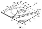
図2は、本明細書のフィルタープレート物品の一実施形態の斜視図を示す。カバーシート140は、好ましくは可撓性であり、典型的に、カバーシート140が最小限の労力でフィルターアセンブリ150から手動で剥離されるように選択される。いくつかの実施形態では、フィルターアセンブリ150も可撓性であり得る。ベース部材110もまた可撓性であり得るが、典型的に、ベース部材110は、自己支持姓であるように選択され、カバーシート140よりも可撓性が低い。
FIG. 2 shows a perspective view of one embodiment of the filter plate article herein. The
図3A及び3Bは、広くは、フィルタープレート物品100の部品及び部品番号に対応する部品及び部品番号を有し(図1A及び1Bを参照)、フィルターアセンブリ350が中にスペーサ層開口394を画定するスペーサ層390を更に備える点において異なり、スペーサ層390は、ベース部材310の第1の主表面301に面するフィルターアセンブリ350の主表面上に載置され、スペーサ層開口394は、フィルターアセンブリ開口354と流体連通する、フィルタープレート物品300の実施形態を示す。本明細書において物品100が言及されるとき、物品100は、物品300について説明されるように、スペーサ層を備えてもよい。
3A and 3B generally have a part and part number corresponding to that of filter plate article 100 (see FIGS. 1A and 1B), with filter assembly 350 defining a spacer layer opening 394 therein. The difference is that it further comprises a
再度図2を参照して、いくつかの代表的な実施形態では、ベース部材110は、第1基材112、第1基材112に接着された任意の第1接着層114、及び任意の第1乾燥コーティング116を含む。第1基材112は、「自己支持性」(すなわち、それ自体の重量を支持することができる)及び「水不透過性」である(すなわち、10重量%を超えるレベルで水を吸収しない)。第1基材112に好適な材料のいくつかの例としては、ポリエステル、ポリプロピレン、又はポリスチレンフィルムが挙げられる。第1基材112に好適な材料の他の例としては、耐水性(例えば、ポリマー)コーティングを備える、紙又は厚紙材料が挙げられる。第1基材112は、第1基材112を通して細菌コロニーを視察することを望むか否かにより、透明、半透明、又は不透明であってよい。細菌コロニーのカウントを容易にするために、第1基材112は、例えば、米国特許第4,565,783号(Hansenら)に記載されるように、上に印刷された正方形格子パターンを有してよい。第1基材112の作製に用いられる材料は、微生物に対して不活性でなければならず、好ましくは無菌化プロセス(例えば、エチレンオキシド滅菌)に適合しなくてはならない。
Referring again to FIG. 2, in some exemplary embodiments, the
図2は、ベース部材110を任意の第1乾燥コーティング116を含むものとして示しているが、いくつかの典型的な実施形態では、ベース部材は、冷水溶性ゲル化剤又は栄養素を含まないことがあり、代わりに、冷水溶性ゲル化剤及び栄養素をカバーシート140内に含む。いくつかのより典型的な実施形態では、カバーシート140は、第2基材142と、任意の第2接着層144と、任意の第2乾燥コーティング146と、を含む。いくつかの実施形態では、任意の第2乾燥コーティング146は、微生物を検出するための検出試薬を含む。いくつかの実施形態では、任意の第2乾燥コーティング146は、栄養培地を含む。
Although FIG. 2 illustrates the
第2基材142は、好ましくは、第2基材142を通して細菌コロニーを視察又は撮像できるように、透明又は半透明であり、約20重量%を超えるレベルで水を吸収しない。第2基材142に好適な材料の非限定例としては、ポリエステル、ポリプロピレン、又はポリスチレンフィルムが挙げられる。好ましくは、カバーシート140は可撓性である。第2基材142の作製に用いられる材料は、微生物に対して不活性でなければならず、好ましくは無菌化プロセス(例えば、エチレンオキシド滅菌)に適合しなくてはならない。
The
物品100のいくつかの実施形態では、ベース部材110は、任意の第1接着層114によって第1基材112に接着された任意の第1乾燥コーティング116を含んでよい。物品100のいくつかの典型的な実施形態では、カバーシート140は、任意の第2接着層144によって第2基材142に接着された任意の第2乾燥コーティング146を含む。典型的な実施形態では、任意の乾燥コーティングは、カバーシート又はベース部材のいずれか1つに含まれ、最も典型的に、任意の乾燥コーティングは、カバーシートのみに含まれる。
In some embodiments of the
物品100に含まれるとき、任意の第1接着層114及び/又は任意の第2接着層144は、典型的に非水溶性である接着材料を含み、微生物の増殖に対して非抑制的でなければならず、滅菌プロセスが用いられる場合は、滅菌プロセスに耐えることができなければならない。好ましくは、接着材料は、ぬれた状態のとき、それが接着されるそれぞれの基材層を通して細菌コロニーを視察できるように十分に透明である。いくつかの実施形態では、接着材料は、感圧性接着剤、例えば、感圧性イソオクチルアクリレート/アクリル酸コポリマー接着剤を含んでよい。好適な感圧性接着剤は、イソオクチルアクリレートを90重量%〜99重量%の範囲で、アクリル酸をアクリル酸の1重量%〜10重量%の範囲で含有し、特に好適な感圧性接着剤は、96重量%のイソオクチルアクリレート及び4重量%のアクリル酸を有する。
When included in the
物品100に含まれるとき、任意の第1乾燥コーティング116及び/又は任意の第2乾燥コーティング146は、例えば、米国特許第4,565,783号(Hansenら)に記載されるように、水溶性ゲル化剤(例えば、グアーガム、キサンタンガム、ローカストビーンガム)を含む。所望により、乾燥コーティング116及び/又は146は、栄養培地、選択剤、検出試薬、又はこれら任意の2つ以上の組み合わせを更に含んでよい。栄養培地、選択剤、及び/又は検出試薬は、ゲル化剤を妨げてはならず、通常は検出される微生物に基づいて選択される。微生物を検出するための好適な栄養素、選択剤、及び検出試薬の例は、例えば、米国特許第4,565,783号(Hansenら)、同第5,089,413号(Nelsonら)、同第5,364,766号(Machら)、同第5,443,963号(Lund)、同第5,462,860号(Mach)、同第5,601,998号(Machら)、同第5,635,367号(Lund)、及び同第5,681,712号(Nelson)において見出すことができる。本明細書で使用するとき、「標準方法栄養素」は、Standard Methods for the Examination of Dairy Products,14th Edition(アメリカ公衆保健協会、ワシントンD.C.)に記載される栄養混合物を指す。5パーツ(重量で)のペプトン、2.5パーツの酵母抽出物、及び1パーツのデキストロースで構成される。栄養培地、選択剤及び/又は検出試薬の量は、所定量の液体試料と接触するとき、これらが微生物の増殖及び/又は検出を促進するように調製される。
When included in the
いくつかの実施形態では、第1乾燥コーティング116及び/又は第2乾燥コーティング146(例えば、乾燥粉末ゲル化剤、所望により乾燥粉末化した栄養素、選択剤及び/又は検出試薬を含む)は、例えば、米国特許第4,565,783号(Hansenら)に記載されるように、接着剤を介して、又は例えば、米国特許第4,565,783号(Hansenら)に記載されるように、ゲル化剤を含む(所望により乾燥粉末化した栄養素、選択剤及び/又は検出試薬を含む)混合液をそれぞれの基材又は接着層の上にコーティングし、続いて混合物を乾燥させることによって、それぞれ第1基材112及び/又は第2基材142に結合されてよい。
In some embodiments, the first
いくつかの実施形態では、第1基材112は、第1基材112の主表面全体を覆う第1乾燥コーティング116を含んでよい。いくつかの実施形態では、第1基材112は、第1基材112の主表面の一部のみを覆う第1乾燥コーティング116を含んでよい。
In some embodiments, the
いくつかの実施形態では、第2基材142は、第2基材142の主表面全体を覆う第2乾燥コーティング146を含んでよい。いくつかの実施形態では、第2基材142は、第2基材142の主表面の一部のみを覆う第2乾燥コーティング146を含んでよい。
In some embodiments, the
典型的な実施形態では、フィルタープレート物品のカバーシート140は、上述の水溶性ゲル化剤を含む第2の乾燥コーティング146を含む。いくつかの典型的な実施形態では、フィルタープレート物品のカバーシート140は、上述の栄養培地を含む第2の乾燥コーティング146を含む。いくつかの典型的な実施形態では、フィルタープレート物品のカバーシート140は、上述の検出試薬を含む第2の乾燥コーティング146を含む。いくつかの典型的な実施形態では、フィルタープレート物品のカバーシート140は、水溶性ゲル化剤、栄養培地、及び検出試薬、又はこれらの任意の組み合わせを含む、第2乾燥コーティング146を含む。水溶性ゲル化剤及び栄養培地をカバーシート140の第2乾燥コーティング146に含めることは、微生物(微多孔性膜160上に存在する場合)を増殖させるために有用であり、検出試薬をカバーシート140の第2乾燥コーティング146に含めることは、微生物増殖の有無の兆候を観察するために有用である。
In an exemplary embodiment, the filter plate
検出試薬を、肉眼で及び/又は自動検出器を用いて検出してよい。自動検出器は画像システムを含んでよい。検出試薬は、発色性、蛍光性、又は発光性であってよい。任意の実施形態では、所定量の液体試料と接触すると、検出試薬は対象微生物を検出するのに十分な濃度に達する。液体試料中の高濃度検出試薬は対象微生物の増殖を阻害もするが、有利には、第1乾燥コーティング116(又は第2乾燥コーティング146)中の検出試薬の量を十分に多くして、対象微生物の存在を迅速に検出してよい。いくつかの実施形態では、第1乾燥コーティング116(又は第2乾燥コーティング146)中の検出試薬の量は、対象微生物の増殖を阻害するものの、対象微生物の検出に十分である。第1乾燥コーティング116(又は第2乾燥コーティング146)中の比較的大量の検出試薬により、その比較的大量の検出試薬が実質的に微生物の増殖を阻害する場合があるが、比較的少量の検出試薬よりも迅速な対象微生物の検出を可能にする。 The detection reagent may be detected with the naked eye and / or using an automatic detector. The automatic detector may include an imaging system. The detection reagent may be chromogenic, fluorescent, or luminescent. In any embodiment, upon contact with a predetermined amount of liquid sample, the detection reagent reaches a concentration sufficient to detect the target microorganism. The high concentration detection reagent in the liquid sample also inhibits the growth of the target microorganism, but advantageously, the amount of detection reagent in the first dry coating 116 (or the second dry coating 146) is increased sufficiently so that the target The presence of microorganisms may be detected quickly. In some embodiments, the amount of detection reagent in the first dry coating 116 (or second dry coating 146) is sufficient to detect the target microorganism, although it inhibits the growth of the target microorganism. Although a relatively large amount of detection reagent in the first dry coating 116 (or second dry coating 146) may cause the relatively large amount of detection reagent to substantially inhibit microbial growth, a relatively small amount of detection reagent. Allows detection of target microorganisms faster than reagents.
検出試薬は、存在する微生物の種類に非特異的な指示薬であってよく、又は存在する微生物の種類に特異的な指示薬であってよい。非特異的検出試薬の非限定例としては、pH指示薬(例えば、アゾベンゼンpH指示薬(例えば、メチルレッド)、スルホンフタレインpH指示薬(例えば、ブロモクレゾールパープル、クロロフェノールレッド、ブロモチモールブルー、ブロモクレゾールブルー)、及びアントラキノン(anthroquinone)pH指示薬(例えば、アリザリンレッドs 3,4−ジヒドロキシ−9,10−ジオキソ−2−アントラセンスルホン酸ナトリウム塩一水和物))及び酸化還元指示薬(例えば、トリフェニルテトラゾリウムクロライド(TTC)、3−[4,5−ジメチルチアゾール−2−イル]−2,5−ジフェニルテトラゾリウムブロマイド(MTT)、2,3−ビス[2−メトキシ−4−ニトロ−5−スルホフェニル(sulfopheny)]−2H−テトラゾリウム−5−カルボキシアニリド分子内塩(XTT)、ニトロブルーテトラゾリウム)が挙げられる。
The detection reagent may be an indicator that is non-specific to the type of microorganism present, or may be an indicator specific to the type of microorganism present. Non-limiting examples of non-specific detection reagents include pH indicators (eg, azobenzene pH indicator (eg, methyl red), sulfonephthalein pH indicator (eg, bromocresol purple, chlorophenol red, bromothymol blue, bromocresol blue). ), And anthroquinone pH indicators (eg, alizarin
検出試薬は、存在する微生物の種類に特異的な指示薬であってよい。特異的検出試薬としては、例えば、特定の微生物又は微生物群に関連する酵素(例えば、グリコシダーゼ、プロテアーゼ、アミノペプチダーゼ、ホスファターゼ、エステラーゼ)の基質が挙げられる。 The detection reagent may be an indicator specific for the type of microorganism present. Specific detection reagents include, for example, substrates for enzymes (eg, glycosidases, proteases, aminopeptidases, phosphatases, esterases) associated with specific microorganisms or groups of microorganisms.
検出試薬は、着色沈殿の形成が可能であってよい。本開示の方法及びデバイスに組み込んでよい様々な染料が周知であり、例えば、5−ブロモ−4−クロロインドリルホスフェート又はこの化合物の二ナトリウム塩、5−ブロモ−4−クロロインドリルピラノシド又はこの化合物の二ナトリウム塩、5−ブロモ−4−クロロ−3インドリル−β−D−グルクロン酸、5−ブロモ−4−クロロ−3−インドキシル−β−D−ガラクトシド、5−ブロモ−4−クロロ−3−インドリル−β−D−グルコピラノシド、6−クロロ−3−インドリルホスフェート、及び5−ブロモ−6−クロロ−3−インドリルホスフェートなどのインドリル含有染料を含む。 The detection reagent may be capable of forming a colored precipitate. Various dyes that may be incorporated into the disclosed methods and devices are well known, such as 5-bromo-4-chloroindolylphosphate or the disodium salt of this compound, 5-bromo-4-chloroindolylpyranoside Or the disodium salt of this compound, 5-bromo-4-chloro-3-indolyl-β-D-glucuronic acid, 5-bromo-4-chloro-3-indoxyl-β-D-galactoside, 5-bromo-4 Indolyl-containing dyes such as -chloro-3-indolyl-β-D-glucopyranoside, 6-chloro-3-indolyl phosphate, and 5-bromo-6-chloro-3-indolyl phosphate.
好ましくは、着色沈殿は青色である。青色沈殿を作る基質としては、例えば、5−ブロモ−4−クロロ−3−インドキシル−N−アセチル−β−D−ガラクトサミニド、5−ブロモ−4−クロロ−3−インドキシル−N−アセチル−β−D−グルコサミニド、5−ブロモ−4−クロロ−3−インドキシル−β−D−セロビオシド、5−ブロモ−4−クロロ−3−β−D−フコピラノシド、5−ブロモ−4−クロロ−3−インドキシル−α−D−ガラクトピラノシド、5−ブロモ−4−クロロ−3−インドキシル−β−ガラクトピラノシド、5−ブロモ−4−クロロ−3−インドキシル−α−D−グルコピラノシド、5−ブロモ−4−クロロ−3−インドキシル−β−D−グルコピラノシド、5−ブロモ−4−クロロ−3−インドキシル−β−D−グルクロン酸、シクロヘキシルアンモニウム塩、5−ブロモ−4−クロロ−3−インドキシル−β−D−グルクロン酸、ナトリウム塩、及び5−ブロモ−4−クロロ−3−インドキシル−β−D−キシロピラノシドが挙げられる。 Preferably, the colored precipitate is blue. Examples of the substrate that forms a blue precipitate include 5-bromo-4-chloro-3-indoxyl-N-acetyl-β-D-galactosaminide, 5-bromo-4-chloro-3-indoxyl-N-acetyl- β-D-glucosaminide, 5-bromo-4-chloro-3-indoxyl-β-D-cellobioside, 5-bromo-4-chloro-3-β-D-fucopyranoside, 5-bromo-4-chloro-3 -Indoxyl-α-D-galactopyranoside, 5-bromo-4-chloro-3-indoxyl-β-galactopyranoside, 5-bromo-4-chloro-3-indoxyl-α-D- Glucopyranoside, 5-bromo-4-chloro-3-indoxyl-β-D-glucopyranoside, 5-bromo-4-chloro-3-indoxyl-β-D-glucuronic acid, cyclohexylammoni Unsalted, 5-bromo-4-chloro-3-indoxyl-beta-D-glucuronic acid, sodium salt, and 5-bromo-4-chloro-3-indoxyl-beta-D-xylopyranoside and the like.
染料は、特定の種類の細菌内に存在する特定の酵素の基質として働くことができる。エステラーゼの基質である青色沈殿生成染料としては、例えば、5−ブロモ−4−クロロ−3−インドキシルブチラート、5−ブロモ−4−クロロ−3−インドキシルカプリレート、及び5−ブロモ−4−クロロ−3−インドキシルパルミテートが挙げられる。ホスファターゼの基質としては、5−ブロモ−4−クロロ−3−インドキシルホスフェートジ(2−アミノ−2−メチル−1,3−プロパンジオール)塩、5−ブロモ−4−クロロ−3−インドキシルホスフェート二ナトリウム塩、5−ブロモ−4−クロロ−3−インドキシルホスフェート及びp−トルイジン塩、5−ブロモ−4−クロロ−3−インドキシルホスフェート及びカリウム塩が挙げられるが、これらに限定されない。 Dyes can serve as substrates for certain enzymes that are present in certain types of bacteria. Examples of blue precipitation-forming dyes that are substrates for esterases include, for example, 5-bromo-4-chloro-3-indoxyl butyrate, 5-bromo-4-chloro-3-indoxyl caprylate, and 5-bromo-4. -Chloro-3-indoxyl palmitate. As a substrate for phosphatase, 5-bromo-4-chloro-3-indoxyl phosphate di (2-amino-2-methyl-1,3-propanediol) salt, 5-bromo-4-chloro-3-indoxyl Examples include, but are not limited to, phosphate disodium salt, 5-bromo-4-chloro-3-indoxyl phosphate and p-toluidine salt, 5-bromo-4-chloro-3-indoxyl phosphate and potassium salt.
グリコシダーゼの基質である発色性染料としては、例えば、3−インドキシル−β−D−ガラクトピラノシド、3−インドキシル−β−D−グルコピラノシド、3−インドキシル−β−D−グルクロン酸シクロヘキシルアンモニウム塩、及び3−インドキシル−β−D−グルクロン酸ナトリウム塩が挙げられる。ホスファターゼ(phophatase)のその他の発色性基質としては、例えば、3−インドキシルホスフェートジ(2−アミノ−2−メチル−1,3−プロパンジオール)塩、及び3−インドキシルホスフェート二ナトリウム塩、3−インドキシルホスフェートp−トルイジン塩が挙げられる。スルファターゼ(sulfatase)の基質としては、例えば、3−インドキシル硫酸カリウム塩が挙げられる。 Examples of chromogenic dyes that are substrates for glycosidases include 3-indoxyl-β-D-galactopyranoside, 3-indoxyl-β-D-glucopyranoside, 3-indoxyl-β-D-cyclohexyl glucuronate. Ammonium salts and 3-indoxyl-β-D-glucuronic acid sodium salt are mentioned. Other chromogenic substrates for phosphatase include, for example, 3-indoxyl phosphate di (2-amino-2-methyl-1,3-propanediol) salt and 3-indoxyl phosphate disodium salt, 3 -Indoxyl phosphate p-toluidine salt. Examples of the substrate for sulfatase include 3-indoxyl sulfate potassium salt.
グリコシダーゼ、エステラーゼ、ホスファターゼ、及びスルファターゼに対するマゼンタ色を出す沈殿性染料としては、例えば、グリコシダーゼの基質としての5−ブロモ−6−クロロ−3−インドキシル−N−アセチル−β−D−グルコサミニド、5−ブロモ−6−クロロ−3−インドキシル−β−D−ガラクトピラノシド、5−ブロモ−6−クロロ−3−インドキシル−β−D−ガラクトピラノシド、5−ブロモ−6−クロロ−3−インドキシル−β−D−グルコピラノシド、及び5−ブロモ−6−クロロ−3−インドキシル−β−グルクロン酸、シクロヘキシルアンモニウム塩;エステラーゼの基質として働く5−ブロモ−6−クロロ−3−インドキシルブチラート、5−ブロモ−6−クロロ−3−インドキシルカプリレート、及び5−ブロモ−6−クロロ−3−インドキシルパルミテート;ホスファターゼに対して5−ブロモ−6−クロロ−3−インドキシルホスフェート、p−トルイジン塩、及びスルファターゼの基質として働く5−ブロモ−6−クロロ−3−インドキシルサルフェート、カリウム塩が挙げられる。 Examples of precipitating dyes that produce a magenta color for glycosidase, esterase, phosphatase, and sulfatase include, for example, 5-bromo-6-chloro-3-indoxyl-N-acetyl-β-D-glucosaminide as a substrate for glycosidase, 5 -Bromo-6-chloro-3-indoxyl-β-D-galactopyranoside, 5-bromo-6-chloro-3-indoxyl-β-D-galactopyranoside, 5-bromo-6-chloro -3-Indoxyl-β-D-glucopyranoside, and 5-bromo-6-chloro-3-indoxyl-β-glucuronic acid, cyclohexylammonium salt; 5-bromo-6-chloro-3-acting as a substrate for esterase Indoxyl butyrate, 5-bromo-6-chloro-3-indoxyl caprylate, and 5-buty Lomo-6-chloro-3-indoxyl palmitate; 5-bromo-6-chloro- which acts as a substrate for 5-bromo-6-chloro-3-indoxyl phosphate, p-toluidine salt, and sulfatase for phosphatase Examples include 3-indoxyl sulfate and potassium salt.
グリコシダーゼ、エステラーゼ、及びホスファターゼに対するサーモン色を出す沈殿性染料としては、例えば、グリコシダーゼに対する6−クロロ−3−インドキシル−β−ガラクトピラノシド、6−クロロ−3−インドキシル−β−D−グルコピラノシド、及び6−クロロ−3−インドキシル−β−D−グルクロン酸、シクロヘキシルアンモニウム塩;エステラーゼに対する6−クロロ−3−インドキシルブチラート、6−クロロ−3−インドキシルカプリレート、及び6−クロロ−3−インドキシルパルミテート;並びにホスファターゼに対する6−クロロ−3−インドキシルホスフェート、p−トルイジン塩が挙げられる。 Precipitating dyes that give a salmon color for glycosidase, esterase, and phosphatase include, for example, 6-chloro-3-indoxyl-β-galactopyranoside, 6-chloro-3-indoxyl-β-D- for glycosidase. Glucopyranoside, and 6-chloro-3-indoxyl-β-D-glucuronic acid, cyclohexylammonium salt; 6-chloro-3-indoxyl butyrate, 6-chloro-3-indoxyl caprylate and 6--6 for esterase Chloro-3-indoxyl palmitate; and 6-chloro-3-indoxyl phosphate, p-toluidine salt for phosphatase.
紫色を出す発色性基質としては、5−ヨード−3−インドキシル−β−D−ガラクトピラノシドが挙げられ、緑色を出す発色性基質としては、N−メチル−インドキシル−β−D−ガラクトピラノシドが挙げられる。 Examples of a chromogenic substrate that emits purple include 5-iodo-3-indoxyl-β-D-galactopyranoside, and examples of a chromogenic substrate that emits green color include N-methyl-indoxyl-β-D- Examples include galactopyranoside.
他の沈殿性染料としては、4,6−ジクロロ−N−アセチルインドール−3−オル、6−クロロインドリル−β−D−ガラクトシドペンタアセテート、6−クロロインドリル−β−D−ガラクトシド、6−クロロインドキシ−1,3−ジアセテート、5−クロロ−2−カルボキシフェニルグリシンナトリウム塩、4−クロロアントラニル酸、メチル[6−クロロ−N−アセチルインドール−3−イル−(2,3,4−トリ−O−アセチル−β−D−グルコピラノシド)]ウロネート、6−クロロインドリル−β−D−グルコピラノシドウロネートモノシクロヘキシルアンモニウム塩、クロロインディゴ(SadlerらのJ.Am Chem.Soc.78:1251〜1255,1956によって報告されたクロロインディゴを含む)、並びに4,6−ジクロロインドリル−β−D−グルクロニド、6,7−ジクロロインドリル−β−D−グルクロニド、6,7−ジクロロインドリル−β−D−グルクロニド、4,6,7−トリクロロインドリル−β−D−グルクロニド、4,6−ジクロロインドリル−β−D−ガラクトシド、6,7−ジクロロインドリル−β−D−ガラクトシド、及び4,6,7−トリクロロインドリル−β−D−ガラクトシドが挙げられる。 Other precipitating dyes include 4,6-dichloro-N-acetylindole-3-ol, 6-chloroindolyl-β-D-galactoside pentaacetate, 6-chloroindolyl-β-D-galactoside, 6 -Chloroindoxy-1,3-diacetate, 5-chloro-2-carboxyphenylglycine sodium salt, 4-chloroanthranilic acid, methyl [6-chloro-N-acetylindol-3-yl- (2,3,3 4-tri-O-acetyl-β-D-glucopyranoside)] uronate, 6-chloroindolyl-β-D-glucopyranoside uronate monocyclohexylammonium salt, chloroindigo (Sadler et al., J. Am Chem. Soc. 78: 1251-1255, 1956, including chloroindigo), and 4,6-dichloroindolyl-β-D-glucuronide, 6,7-dichloroindolyl-β-D-glucuronide, 6,7-dichloroindolyl-β-D-glucuronide, 4,6,7-trichloroin Drill-β-D-glucuronide, 4,6-dichloroindolyl-β-D-galactoside, 6,7-dichloroindolyl-β-D-galactoside, and 4,6,7-trichloroindolyl-β-D -Galactoside is mentioned.
好適な検出試薬としては更に、非沈殿性指示染料(すなわち、ヒドロゲル中に拡散可能な水溶性染料)が挙げられる。非沈殿性指示染料としては、pH指示薬(例えば、本明細書に記載するアゾベンゼンpH指示薬、スルホンフタレインpH指示薬、及びアントラキノン(anthroquinone)pH指示薬)が挙げられる。また、非沈殿性指示染料としては、酵素と反応して水溶性染料(例えば、それぞれ加水分解されてp−ニトロフェノールとなり得るp−ニトロフェニルホスフェート又はp−ニトロフェニル−β−D−グルコシド)を放出する発色性酵素基質、及び、酵素と反応して水溶性蛍光染料(例えば、それぞれ加水分解されて4−メチルウンベリフェロンとなり得る4−メチルウンベリフェリルホスフェート又は4−メチルウンベリフェリル−β−D−グルコシド)を放出する蛍光性酵素基質も挙げられる。 Suitable detection reagents further include non-precipitating indicator dyes (ie, water-soluble dyes that can diffuse into the hydrogel). Non-precipitating indicator dyes include pH indicators (eg, azobenzene pH indicator, sulfonephthalein pH indicator, and anthroquinone pH indicator as described herein). Further, as the non-precipitating indicator dye, a water-soluble dye (for example, p-nitrophenyl phosphate or p-nitrophenyl-β-D-glucoside, which can be hydrolyzed to p-nitrophenol, respectively) reacts with an enzyme. A chromogenic enzyme substrate to be released and a water-soluble fluorescent dye that reacts with the enzyme (eg, 4-methylumbelliferyl phosphate or 4-methylumbelliferyl-β, each of which can be hydrolyzed to 4-methylumbelliferone, respectively) Also included are fluorescent enzyme substrates that release (D-glucoside).
図1A及び1Bに示される物品100の実施形態では、フィルターアセンブリ150は、内部に画定されたフィルターアセンブリ開口154を有するフィルター支持層158、及びフィルターアセンブリ開口にわたって載置された複合フィルター本体155を有するように示される。フィルター支持層158は、複合フィルター本体155に対して構成される。フィルター支持層158は、好ましくは、自己支持性であり、10重量%未満のレベルで水を吸収しないか、又は水を吸収する。フィルター支持層158に好適な材料の非限定例としては、ポリエステル、ポリプロピレン、又はポリスチレンフィルムが挙げられる。その他の好適な材料としては、防水(例えば、ポリマー)コーティングを含む紙又は厚紙材料が挙げられる。フィルター支持層158は、透明、半透明、又は不透明であってよい。所望により、フィルター支持層158は、ベース部材110及び/又はカバーシート140の周囲境界部を超えて延びるタブ領域151を備えてよい。
In the embodiment of the
フィルター支持層158は、内部に画定されたフィルターアセンブリ開口154を更に備え、ベース部材110からフィルターアセンブリ150を通してカバーシート140に至る流体連通を可能にする。フィルターアセンブリ開口154は、例えば、円形、正方形、矩形、六角形、八角形、楕円形、又は不整形などの任意の形状であってよい。
The
複合フィルター本体155は、微多孔性膜160及び吸水性層180を含み、図1Aにおいて、微多孔性膜160及び吸水性層180は、フィルター支持層158の対向主表面上に載置され、間に間隙170を画定するように示される。吸水性層180は、微多孔性膜160と流体連通する。当然のことながら、いくつかの実施形態では、微多孔性膜160の少なくとも一部は、吸水性層180の少なくとも一部と接触してよく、またいくつかの実施形態では、間隙170は、フィルターアセンブリ開口154にわたって連続しないことがあり、いくつかの実施形態では、微多孔性膜160及び吸水性層は、他の、フィルターアセンブリ開口154によって画定された領域全体で互いに接触してよい。
The
使用中、微多孔性膜160の少なくとも一部がフィルターアセンブリ開口154を覆うように、微多孔性膜160を配置しなくてはならない。好ましくは、使用中、微多孔性膜160がフィルターアセンブリ開口154を覆うように、微多孔性膜160を配置する。いくつかの実施形態では、微多孔性膜160の面積は、フィルターアセンブリ開口154の面積より大きく、微多孔性膜160は、フィルターアセンブリ開口154の外辺部を超えて広がる。
In use, the
図3A及び3Bに示される物品300の実施形態では、フィルターアセンブリ350は、内部にスペーサ層開口394を画定するスペーサ層390を更に含み、スペーサ層390は、ベース部材310の第1主表面301に面するフィルター支持層358の主表面上に載置され、スペーサ層開口394は、フィルターアセンブリ開口354と流体連通する。スペーサ層390は、非水溶性材料から作製されるべきである。開口スペーサ層の壁は、フィルター支持層358と一緒に、所定寸法及び形状の液体試料ウェルを形成し、物品300内の液体試料(例えば、水性試料)の体積を制限する。所望の容量(例えば、1ミリリットル、2ミリリットル、3ミリリットル、5ミリリットル、又はそれ以上)のウェルを形成するために、スペーサ層390は十分に厚く、スペーサ層開口394は十分に大きくあるべきである。独立気泡ポリエチレン発泡体又はポリスチレン発泡体は、スペーサ層390に好適な材料であるが、疎水性(非濡れ性)であり、微生物に対して不活性であり、好ましくは無菌化プロセスに耐えることができる任意の材料が使用され得る。スペーサ層390は、例えば、米国特許第4,565,783号(Hansenら)に記載されるように、例えば、接着剤によってフィルター支持層358に結合することができる。
In the embodiment of the
図4A〜4Dは、フィルターアセンブリ開口454A〜Dにわたって、微多孔性膜460A〜D及び吸水性層480A〜Dを位置付けるためのいくつかの代替実施形態を示す。図4Aは、本質的に図1A及び1Bのフィルターアセンブリ150と同一の特徴を有するが、複合フィルター本体455A内で、微多孔性膜460Aと吸水性層480Aとの間に位置付けられた任意のスクリム475Aを含む、フィルターアセンブリ450Aを示す。任意のスクリム475Aは、吸水性層480Aと微多孔性膜460Aとの流体連通を維持しながら、複合フィルター本体455Aを補強するために有用であり得る。スクリム材料は、以下の吸水性層のより詳細な説明に沿って説明される。
4A-4D illustrate several alternative embodiments for positioning the
図4Bは、フィルターアセンブリ開口454Bにわたって載置された複合フィルター本体455Bを有するフィルターアセンブリ450Bの一実施形態を示し、複合フィルター本体455Bは、フィルター支持層458Bの1つの主表面のみと接触し、吸水性層480Bは、微多孔性膜460Bとフィルター支持層458Bの主表面との間に位置付けられる。
FIG. 4B illustrates one embodiment of a
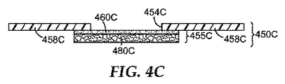
図4Cは、フィルターアセンブリ開口454Cにわたって載置された複合フィルター本体455Cを有するフィルターアセンブリ450Cの一実施形態を示し、複合フィルター本体455Cは、フィルター支持層458Cの1つの主表面のみと接触し、吸水性層460Cは、吸水性層480Cとフィルター支持層458Cの主表面との間に位置付けられる。
FIG. 4C shows one embodiment of a
図4Dは、フィルターアセンブリ450Dの一実施形態を示し、複合フィルター本体455Dの外辺部は、フィルターアセンブリ開口454D内に適合する。
FIG. 4D shows one embodiment of a
図1A及び4A〜4Dの実施形態のいずれかでは、複合フィルター本体155(又は455A〜D)をフィルター支持層158(又は458A〜D)の上に載置するために、少なくとも1つのガスケットが提供されてよく、例えば、図4Dに示されるように、複合フィルター本体455Dをフィルター支持層458Dに固定するために、少なくとも1つのガスケット490Dが提供されてよい。ガスケットは、任意の好適な材料、例えば、二軸延伸ポリプロピレン(BOPP)で作製されてよく、複合フィルター本体155(又は455A〜D)及びフィルター支持層の両方を固定するために接着剤の層を更に含んでもよい。図1Aに示される実施形態では、例えば、微多孔性膜160をフィルター支持層158の第1主表面の上に載置するために、第1ガスケット(図1Aには示されない)が提供されてよく、吸水性層180をフィルター支持層158の第2主表面の上に載置するために、第2ガスケット(図1Aには示されない)が提供されてよい。
In any of the embodiments of FIGS. 1A and 4A-4D, at least one gasket is provided for mounting the composite filter body 155 (or 455A-D) on the filter support layer 158 (or 458A-D). For example, as shown in FIG. 4D, at least one
当業者であれば、複合フィルター本体155の構成要素をフィルター支持層158の上に載置するための追加の技法が好適であり得ることを認識し、それには、例えば、接着、熱接着、超音波溶接、又はそれらの組み合わせが挙げられる。
Those skilled in the art will recognize that additional techniques for placing the components of the
微多孔性膜160(又は微多孔性膜460A〜Dのいずれか)は、当該技術分野において既知である様々な透水性微多孔性膜材料のうちのいずれかを含んでよく、例えば、セルロース系膜(例えば、酢酸セルロース、混合セルロースエステル、ニトロセルロース)、ナイロン、ポリカーボネート、ポリエーテルスルホン、ナイロン、ポリエステル、ポリフッ化ビニリデン、セラミックス、これら任意のものの誘導体、及びこれら任意のものの2つ以上の組み合わせが挙げられる。微多孔性膜160の公称孔径は、典型的に、検出される微生物に応じて選択される。例えば、0.05マイクロメートル〜1.2マイクロメートルの範囲の公称孔径(0.05マイクロメートル、0.1マイクロメートル、0.2マイクロメートル、0.45マイクロメートル、0.8マイクロメートル、又は1.2マイクロメートルのうちのいずれかを含む)、又はいくつかの実施形態では、0.2マイクロメートル〜0.45マイクロメートルの範囲を使用して、細菌を検出することができる。いくつかの実施形態では、0.05マイクロメートル〜3マイクロメートルの範囲の公称孔径(0.45マイクロメートル、0.8マイクロメートル、1.2マイクロメートル、又は3マイクロメートルのうちのいずれかを含む)、又はいくつかの実施形態では、0.45マイクロメートル〜1.2マイクロメートルの範囲を使用して、細菌を検出することができる。任意の実施形態では、微多孔性膜は、フィルターアセンブリを通して濾過された水性試料から微生物を回収するように構成されるべきである。水透過性試験の測定値は、例えば、ASTM F2298−03に記載されるものを含んでよい。
The microporous membrane 160 (or any of the
有用な市販の微多孔性膜の例としては、3M Purification,Inc.(Meriden,CT)から商品名「LIFEASSURE」及び「STERASSURE」で入手可能な鋳造ナイロン微多孔性膜が挙げられる。有用な微多孔性膜は、例えば、米国特許第6,413,070号(Meyeringら)、同第6,513,666号(Meyeringら)、同第6,776,940号(Meyeringら)、同第6,056,529号(Meyeringら)、同第6,264,044号(Meyeringら)、同第5,006,247号(Dennisonら)、米国特許第3,876,738号(Marinaccioら)、同第4,707,265号(Barnesら)、及び同第4,473,474号(Ostreicherら)において説明されている。有用なグラフトポリマー機能性微多孔性膜は、2010年10月14日に公開された米国公開特許出願第2010/0261801号(Weissら)において説明されている。 Examples of useful commercially available microporous membranes include 3M Purification, Inc. Cast nylon microporous membranes available from (Meriden, CT) under the trade names “LIFEASSURE” and “STERASSURE”. Useful microporous membranes include, for example, US Pat. Nos. 6,413,070 (Meyering et al.), 6,513,666 (Meyering et al.), 6,776,940 (Meyering et al.), 6,056,529 (Meyering et al.), 6,264,044 (Meyering et al.), 5,006,247 (Denison et al.), US Pat. No. 3,876,738 (Marinaccio) Et al., 4,707,265 (Barnes et al.), And 4,473,474 (Ostricher et al.). Useful graft polymer functional microporous membranes are described in US Published Patent Application No. 2010/0261801 (Weiss et al.) Published Oct. 14, 2010.
物品100のいくつかの実施形態では、複合フィルター本体155内の吸水性層180は、グラフトされたヒドロゲルポリマーで官能化された繊維基質を含む。いくつかの実施形態では、繊維基質は不織布基質である。本明細書で使用するとき、用語「不織布」は、繊維の結合若しくは絡合、又はこの両方によって作製され、ASTM D123−09e1に従って、機械的、化学的、熱的、又は溶媒的手段、及び組み合わせによって実現されるテキスタイル構造体を意味する。
In some embodiments of the
いくつかの実施形態では、吸水性層180は、グラフトされたヒドロゲルポリマーで官能化された織布基材である繊維基材を含むことができる。本明細書で使用するとき、「織布基材」は布又は織物を含んでよい。本明細書で使用するとき、用語「織布」は、所定の織り合わせパターンに従って、かつ、ASTM D123−09e1に従って少なくとも1組の撚り糸が布地の縦方向沿いの軸に平行になるように、少なくとも組の撚り糸を、通常は互いに直角を成すように織り合わせると作製される構造体を意味する。これらの基材は、典型的に、天然繊維(例えば、綿又は羊毛)、合成繊維(例えば、ナイロン、ポリエステル、アクリロニトリル)、又はそれらの混合から作製される。本明細書に記載のグラフト化学は、主に不織布基材に関するものであるが、当然のことながら、グラフト化学は、フィルタープレート物品100内の吸水性層180として使用するための織布基材に適用することもできる。
In some embodiments, the water-
繊維基材は、0.7マイクロメートル〜15マイクロメートルの範囲の平均繊維径を有し、50%〜95%の範囲の空隙容積を有してよい。 The fiber substrate may have an average fiber diameter in the range of 0.7 micrometers to 15 micrometers and have a void volume in the range of 50% to 95%.
グラフトされたヒドロゲルポリマーは、不織布基材の表面にグラフトされたグラフト化モノマー単位を含み、グラフト化モノマー単位は、イオングラフト化モノマー単位、非イオングラフト化モノマー単位、及びそれらの混合物からなる群から選択される。いくつかの実施形態では、グラフトされたヒドロゲルポリマーは、カチオン性アミノアルキル(メタ)アクリロイルモノマー単位(以下に記載)を含む、カチオン性ヒドロゲルポリマー、例えば(3−[(メタクリロイルアミノ)プロピル]トリメチル塩化アンモニウム)(MAPTAC)であって、繊維基材の表面にグラフトされる。いくつかの他の実施形態では、グラフトされたヒドロゲルポリマーは、アニオン性モノマー単位(以下に記載)を含む、アニオン性ヒドロゲルポリマー、例えば、2−アクリルアミド−2−メチルプロパンスルホン酸(AMPS)であって、繊維基材の表面にグラフトされる。いくつかの他の実施形態では、グラフトされたヒドロゲルポリマーは、非イオン親水性モノマー単位(以下に記載)を含む、非イオンヒドロゲルポリマー、例えば、ジメチルアクリルアミド(DMA)又は2−ヒドロキシエチル(メタ)アクリレート(HEMA)であって、繊維基材の表面にグラフトされる。いくつかの実施形態では、グラフトされヒドロゲルポリマーは、繊維基材の表面にグラフトされたカチオン性アミノアルキル(メタ)アクリロイルモノマー単位及びアニオン性モノマー単位の組み合わせである。いくつかの実施形態では、グラフトされたヒドロゲルポリマーは、繊維基材の表面にグラフトされたイオン(カチオン性及び/又はアニオン性)及び非イオン親水性モノマーである。 The grafted hydrogel polymer comprises grafted monomer units grafted to the surface of the nonwoven substrate, the grafted monomer units from the group consisting of ion grafted monomer units, non-ion grafted monomer units, and mixtures thereof. Selected. In some embodiments, the grafted hydrogel polymer comprises a cationic hydrogel polymer comprising cationic aminoalkyl (meth) acryloyl monomer units (described below), such as (3-[(methacryloylamino) propyl] trimethyl chloride. Ammonium) (MAPTAC), which is grafted onto the surface of the fiber substrate. In some other embodiments, the grafted hydrogel polymer is an anionic hydrogel polymer comprising anionic monomer units (described below), such as 2-acrylamido-2-methylpropane sulfonic acid (AMPS). And grafted onto the surface of the fiber substrate. In some other embodiments, the grafted hydrogel polymer comprises a nonionic hydrophilic monomer unit (described below), such as a nonionic hydrogel polymer, such as dimethylacrylamide (DMA) or 2-hydroxyethyl (meth). Acrylate (HEMA), which is grafted to the surface of the fiber substrate. In some embodiments, the grafted hydrogel polymer is a combination of cationic aminoalkyl (meth) acryloyl monomer units and anionic monomer units grafted onto the surface of the fiber substrate. In some embodiments, the grafted hydrogel polymer is ionic (cationic and / or anionic) and non-ionic hydrophilic monomers grafted onto the surface of the fiber substrate.
いくつかの実施形態では、繊維基材は不織布ウェブであり、不織布ウェブの製造のための周知のプロセスのいずれかにより製造される不織布ウェブを含んでよい。本明細書で使用するとき、用語「不織布ウェブ」は、マット状の層間に、不規則に及び/又は一定方向に入れられた個々の繊維又はフィラメントの構造を有する布地を意味する。 In some embodiments, the fiber substrate is a nonwoven web and may include a nonwoven web produced by any of the well-known processes for the production of nonwoven webs. As used herein, the term “nonwoven web” refers to a fabric having a structure of individual fibers or filaments that are randomly and / or oriented in a matted layer.
例えば、不織布ウェブは、カード、エアレイド、ウェットレイド、スパンレース、スパンボンド、電界紡糸、又はメルトスパン若しくはメルトブローンなどのメルトブローン法、あるいはこれらの組み合わせによって製造されることができる。スパンボンド繊維は、典型的には、押し出される繊維の直径を持つ微細で通常は円形をした複数の紡糸口金の毛管から、溶融した熱可塑性ポリマーをフィラメントとして押し出し、急激に縮小させることにより形成された小径繊維である。メルトブロー繊維は、典型的には、溶融した熱可塑性物質を、融解した糸又はフィラメントとして、複数の微細で通常は円形のダイキャピラリーを通して、溶融した熱可塑性物質のフィラメントを弱めてその直径を縮小させる高速の、通常は加熱されたガス(例えば、空気)の流れの中に押し出すことによって形成されている。その後、高速ガス流によって、メルトブロー繊維は移動され収集面上に堆積し、無作為に分散されたメルトブロー繊維のウェブを形成する。任意の不織布ウェブは、熱可塑性ポリマーの種類及び/又は厚さが異なる単一の繊維又は2つ以上の繊維から製造されてよい。 For example, the nonwoven web can be produced by card, airlaid, wet laid, spunlace, spunbond, electrospinning, or meltblown processes such as meltspun or meltblown, or combinations thereof. Spunbond fibers are typically formed by extruding molten thermoplastic polymer as filaments from a plurality of fine, usually circular, spinneret capillaries with the diameter of the extruded fibers and abruptly shrinking. Small diameter fiber. Meltblown fibers typically melt molten thermoplastic as melted yarns or filaments through a plurality of fine, usually circular die capillaries, weakening the molten thermoplastic filament and reducing its diameter. It is formed by extruding into a stream of high speed, usually heated gas (eg, air). Thereafter, the high velocity gas stream causes the meltblown fibers to move and deposit on the collection surface to form a randomly dispersed web of meltblown fibers. Any nonwoven web may be made from a single fiber or two or more fibers of different thermoplastic polymer types and / or thicknesses.
ステープルファイバーもまた、ウェブ内に存在してよい。一般に、ステープルファイバーが存在することで、ブローマイクロファイバーのみからなるウェブよりも、より嵩高でより密度の低いものとなる。好ましくは、20重量%(重量パーセント)以下、より好ましくは10重量%以下のステープルファイバーが存在する。ステープルファイバーを含有するそのようなウェブは、米国特許第4,118,531号(Hauser)に開示されている。 Staple fibers may also be present in the web. In general, the presence of staple fibers makes them bulkier and less dense than webs consisting solely of blown microfibers. Preferably, no more than 20 wt% (weight percent), more preferably no more than 10 wt% staple fiber is present. Such webs containing staple fibers are disclosed in US Pat. No. 4,118,531 (Hauser).
繊維基材は、所望により、例えば1つ以上のスクリム層を更に含んでよい。例えば、主表面の一方又は両方は、所望により、スクリム層を含んでもよい。典型的には、繊維から製造される織布又は不織布の補強材であるスクリムは、不織布基材に強度を提供するために含まれる。好適なスクリム材料には、ナイロン、ポリエステル、繊維ガラス等が挙げられるが、これらに限定されない。スクリムの平均厚さは様々であり得る。典型的に、スクリムの平均厚さは、25マイクロメートル〜100マイクロメートルの範囲であるか、又はいくつかの実施形態では、25マイクロメートル〜50マイクロメートルの範囲である。スクリムの層は、所望により、不織布基材に接合されてもよい。様々な接着剤を使用して、スクリムをポリマー材料に接合することができる。別の方法としては、スクリムは、不織布に熱接合されてもよい。 The fiber substrate may further include, for example, one or more scrim layers, if desired. For example, one or both of the major surfaces may optionally include a scrim layer. Typically, scrims, which are woven or nonwoven reinforcements made from fibers, are included to provide strength to the nonwoven substrate. Suitable scrim materials include, but are not limited to, nylon, polyester, fiberglass, and the like. The average thickness of the scrim can vary. Typically, the average thickness of the scrim is in the range of 25 micrometers to 100 micrometers, or in some embodiments, in the range of 25 micrometers to 50 micrometers. The scrim layer may be bonded to the nonwoven substrate if desired. A variety of adhesives can be used to join the scrim to the polymeric material. Alternatively, the scrim may be thermally bonded to the nonwoven.
不織布基材のマイクロファイバーは、典型的には、Davies,C.N.、「The Separation of Airborne Dust and Parcticles」、(Institution of Mechanical Engineers,London,Proceedings 1B,1952)に記載された方法により計算した場合に、0.5マイクロメートル〜15マイクロメートル、好ましくは1マイクロメートル〜6マイクロメートルの有効繊維直径を有する。不織布基材は、好ましくは、10〜400g/m2(1平方メートルあたりのグラム)、より好ましくは10〜100g/m2の坪量を有する。不織布基材の平均厚さは、非官能化、カレンダー加工されていない基材の場合、好ましくは0.1ミリメートル〜10ミリメートル、より好ましくは0.25ミリメートル〜5ミリメートルである。不織布ウェブの最小引張強度は、約4ニュートンである。不織布の引張強度は、ウェブ横断方向における良好な繊維接合及び絡み合いに起因して、ウェブ横断方向よりも機械方向で低いことは一般に認識されている。 Nonwoven nonwoven microfibers are typically manufactured by Davies, C .; N. , Preferably 0.5 micrometers to 15 micrometers when calculated by the method described in “The Separation of Airline Dust and Particles” (Institution of Mechanical Engineers, London, Processings 1B, 1952). Has an effective fiber diameter of ~ 6 micrometers. The nonwoven substrate preferably has a basis weight of 10 to 400 g / m 2 (grams per square meter), more preferably 10 to 100 g / m 2 . The average thickness of the nonwoven substrate is preferably from 0.1 millimeters to 10 millimeters, more preferably from 0.25 millimeters to 5 millimeters, for non-functionalized, non-calendered substrates. The minimum tensile strength of the nonwoven web is about 4 Newtons. It is generally recognized that the tensile strength of nonwovens is lower in the machine direction than in the cross-web direction due to good fiber bonding and entanglement in the cross-web direction.
不織布ウェブの嵩は、ソリディティ(ウェブの体積の固体分率を定義するパラメータ)で測定される。低いソリディティ値は、ウェブの嵩が大きいことを示す。有用な不織布基材は、20%未満、好ましくは15%未満のソリディティを有する。ソリディティは、典型的にはαとして表わされる無単位の分数である。
α=mf÷ρf×L不織布
式中、mfは、サンプル表面積あたりの繊維質量であり、ρfは繊維密度であり、
L不織布
は不織布の厚さである。ソリディティは、本明細書では不織布基材そのものを対象にして使用され、官能化不織布は対象とならない。不織布基材が2種類以上の繊維の混合物を含む場合、同じL不織布を用いて繊維のそれぞれの種類に対して個々のソリディティが決定され、これら個々のソリディティを合計すると、ウェブのソリディティαが得られる。
The bulk of the nonwoven web is measured by solidity (a parameter that defines the solid fraction of the web volume). A low solidity value indicates that the web is bulky. Useful nonwoven substrates have a solidity of less than 20%, preferably less than 15%. Solidity is a unitless fraction, typically expressed as α.
α = m f ÷ ρ f × L non-woven fabric
Where m f is the fiber mass per sample surface area, ρ f is the fiber density,
L non-woven fabric
Is the thickness of the nonwoven fabric. Solidity is used herein for the nonwoven substrate itself, not functionalized nonwovens. If the nonwoven substrate contains a mixture of two or more types of fibers, individual solidities are determined for each type of fiber using the same L nonwoven , and the sum of these individual solidities yields the web solidity α. It is done.
いくつかの実施形態では、不織布基材は、1マイクロメートル〜40マイクロメートルの平均孔径、又はいくつかの実施形態では、更に2マイクロメートル〜20マイクロメートルの平均孔径を有する。平均孔径は、泡立ち点による膜フィルターの孔径特徴のためのASTM F316−03標準試験方法、及び平均流量孔試験方法Bに従って、DuPont(Wilmington,DE)から商品名「FREON TF」で入手可能な試験流体を使用して測定されてよい。 In some embodiments, the nonwoven substrate has an average pore diameter of 1 micrometer to 40 micrometers, or in some embodiments, an additional average pore diameter of 2 micrometers to 20 micrometers. The average pore size is a test available under the trade name “FREON TF” from DuPont (Wilmington, DE) according to ASTM F316-03 standard test method and average flow rate pore test method B for pore size characteristics of membrane filters by bubble point. It may be measured using a fluid.
不織布基材は、任意の好適な熱可塑性ポリマー材料から形成されてもよい。好適な高分子物質には、ポリオレフィン、ポリ(イソプレン)、ポリ(ブタジエン)、フッ素化ポリマー、塩素化ポリマー、ポリアミド、ポリイミド、ポリエーテル、ポリ(エーテルスルホン)、ポリ(スルホン)、ポリ(ビニルアセテート)、ビニルアセテートのコポリマー(例えば、ポリ(エチレン)−コ−ポリ(ビニルアルコール))、ポリ(ホスファゼン)、ポリ(ビニルエステル)、ポリ(ビニルエーテル)、ポリ(ビニルアルコール)、及びポリ(カーボネート)が挙げられるが、これらに限定されない。 The nonwoven substrate may be formed from any suitable thermoplastic polymer material. Suitable polymeric materials include polyolefin, poly (isoprene), poly (butadiene), fluorinated polymer, chlorinated polymer, polyamide, polyimide, polyether, poly (ether sulfone), poly (sulfone), poly (vinyl acetate) ), Vinyl acetate copolymers (eg, poly (ethylene) -co-poly (vinyl alcohol)), poly (phosphazene), poly (vinyl ester), poly (vinyl ether), poly (vinyl alcohol), and poly (carbonate) However, it is not limited to these.
不織布基材に好適なポリオレフィンには、ポリ(エチレン)、ポリ(プロピレン)、ポリ(1−ブテン)、エチレンとプロピレンのコポリマー、αオレフィンコポリマー(例えば、1−ブテン、1−ヘキセン、1−オクテン、及び1−デセンとエチレン又はプロピレンのコポリマー)、ポリ(エチレン−コ−1−ブテン)、及びポリ(エチレン−コ−1−ブテン−コ−1−ヘキセン)が挙げられるが、これらに限定されない。 Polyolefins suitable for nonwoven substrates include poly (ethylene), poly (propylene), poly (1-butene), copolymers of ethylene and propylene, alpha olefin copolymers (eg, 1-butene, 1-hexene, 1-octene). And copolymers of 1-decene and ethylene or propylene), poly (ethylene-co-1-butene), and poly (ethylene-co-1-butene-co-1-hexene), but are not limited to these. .
不織布基材に好適なフッ素化ポリマーには、ポリ(フッ化ビニル)、ポリ(フッ化ビニリデン)、フッ化ビニリデンのコポリマー(例えばポリ(フッ化ビニリデン−コ−ヘキサフルオロプロピレン)、及びクロロトリフルオロエチレンのコポリマー(例えばポリ(エチレン−コ−クロロトリフルオロエチレン)が挙げられるが、これらに限定されない。 Fluorinated polymers suitable for nonwoven substrates include poly (vinyl fluoride), poly (vinylidene fluoride), copolymers of vinylidene fluoride (eg, poly (vinylidene fluoride-co-hexafluoropropylene), and chlorotrifluoro Copolymers of ethylene (such as, but not limited to, poly (ethylene-co-chlorotrifluoroethylene)).
不織布基材に好適なポリアミドには、ナイロン6、ナイロン6,6、ナイロン6,12ポリ(イミノアジポイルイミノヘキサメチレン)、ポリ(イミノアジポイルイミノデカメチレン)、及びポリカプロラクタムが挙げられるが、これらに限定されない。好適なポリイミドには、ポリ(ピロメリットイミド)が挙げられる。
Suitable polyamides for nonwoven substrates include
不織布基材に好適なポリ(エーテルスルホン)には、ポリ(ジフェニルエーテルスルホン)及びポリ(ジフェニルスルホン−コジフェニレンオキシドスルホン)が挙げられるが、これらに限定されない。 Suitable poly (ether sulfones) for the nonwoven substrate include, but are not limited to, poly (diphenyl ether sulfone) and poly (diphenyl sulfone-codiphenylene oxide sulfone).
不織布基材に好適なビニルアセテートのコポリマーには、ポリ(エチレン−コ−ビニルアセテート)、及びアセテート基の少なくとも一部が加水分解されていて、ポリ(エチレン−コ−ビニルアルコール)などの種々のポリ(ビニルアルコール)を与えるコポリマーが挙げられるが、これらに限定されない。 Vinyl acetate copolymers suitable for nonwoven substrates include poly (ethylene-co-vinyl acetate) and various types such as poly (ethylene-co-vinyl alcohol) in which at least some of the acetate groups are hydrolyzed. Examples include, but are not limited to, copolymers that give poly (vinyl alcohol).
いくつかの実施形態では、不織布基材のポリマーは、本質的に疎水性であり、e−ビーム又はガンマ線などの電離放射線によって容易にグラフトされる。有用なポリマーには、ポリアミド並びにエチレンビニルアルコールポリマー及びコポリマーが含まれる。1マイクロメートル以下の有効繊維直径を有するナイロン不織布基材は、例えば、米国特許第7,170,739号(Aroraら)、同第7,112,389号(Aroraら)、同第7,235,122号(Brynerら)、及び米国公開特許出願第2004/0116026号に記載されるものから選択されてよい。1ミクロン以下の有効繊維直径を有する有用なナイロン不織布基材には、例えば、DuPont(Wilmington,DE)から商品名「HMT 16434」及び「HMT 16435」で入手可能なハイブリッド膜技術膜が挙げられる。 In some embodiments, the nonwoven substrate polymer is hydrophobic in nature and is readily grafted by ionizing radiation, such as e-beam or gamma radiation. Useful polymers include polyamides and ethylene vinyl alcohol polymers and copolymers. Nylon nonwoven substrates having an effective fiber diameter of 1 micrometer or less include, for example, U.S. Patent Nos. 7,170,739 (Arora et al.), 7,112,389 (Arora et al.), And 7,235. , 122 (Bryner et al.), And those described in US Published Patent Application No. 2004/0116026. Useful nylon nonwoven substrates having an effective fiber diameter of 1 micron or less include, for example, hybrid membrane technology membranes available from DuPont (Wilmington, DE) under the trade designations “HMT 16434” and “HMT 16435”.
この説明の不織布基材の製造方法に関する更なる詳細は、例えば、Wente,Superfine Thermoplastic Fibers,48 Indus.Eng.Chem.1342(1956)、又はWenteらのManufacture Of Superfine Organic Fibers(Naval Research Laboratories Report No.4364、1954)において見出され得る。不織布基材を調製する有用な方法は、例えば、米国第RE39,399号(Allen)、及び米国特許第3,849,241号(Butinら)、同第7,374,416号(Cookら)、同第4,936,934号(Buehning)、及び同第6,230,776号(Choi)に記載されている。 Further details regarding the method of manufacturing the nonwoven substrate of this description can be found in, for example, Wente, Superfine Thermoplastic Fibers, 48 Indus. Eng. Chem. 1342 (1956), or Manufacture Of Superfine Organic Fibers (Naval Research Laboratories Report No. 4364, 1954) of Wente et al. Useful methods for preparing nonwoven substrates include, for example, US Pat. No. RE39,399 (Allen) and US Pat. Nos. 3,849,241 (Butin et al.), 7,374,416 (Cook et al.). No. 4,936,934 (Buehning), and No. 6,230,776 (Choi).
典型的な実施形態では、グラフトされたヒドロゲルポリマーは、不織布基材から始まる、及び不織布基材によって支持される、ポリマー鎖(tendrils)を含み、ポリマー巻きひげは、不織布基材の格子間間隙の中に延びる。不織布基材のいくつかの実施形態では、グラフトされたヒドロゲルポリマー鎖は、カチオン性であるペンダント基を有する。不織布基材のいくつかの他の実施形態では、グラフトされたヒドロゲルポリマー鎖は、アニオン性であるペンダント基を有する。不織布基材のいくつかの実施形態では、グラフトされたヒドロゲルポリマー鎖は、非イオン親水性官能基(以下に記載)であるペンダント基を有する。純水の存在下で、ヒドロゲルは、最大水和及び体積の状態に達する。ポリマー巻きひげは、独立して自由に移動し得るため、グラフトされたヒドロゲルポリマーを有する不織布基材は、極めて低量の刺激に対して大きい流量応答を有し得る。 In an exemplary embodiment, the grafted hydrogel polymer comprises polymer chains (tendrils) starting from and supported by the nonwoven substrate, wherein the polymer whiskers are interstitial gaps of the nonwoven substrate. Extends inside. In some embodiments of the nonwoven substrate, the grafted hydrogel polymer chain has pendant groups that are cationic. In some other embodiments of the nonwoven substrate, the grafted hydrogel polymer chains have pendant groups that are anionic. In some embodiments of the nonwoven substrate, the grafted hydrogel polymer chain has pendant groups that are non-ionic hydrophilic functional groups (described below). In the presence of pure water, the hydrogel reaches a maximum hydration and volume state. Because polymer whiskers can move freely independently, nonwoven substrates with grafted hydrogel polymers can have a large flow response to very low amounts of stimulation.
不織布基材の置換度、及びその表面にグラフトされたヒドロゲルポリマーの重量に応じて、グラフトされたヒドロゲルポリマーは、不織布基材の格子間間隙を完全に充満し、これにより、官能化不織布物品を通る純水の流れを有効に遮断するバリアを提供することができる。ヒドロゲルネットワークとして存在すると考慮され得る、グラフトされたヒドロゲルポリマーは、塩、緩衝液、有機溶媒、温度、又はpHなどの極めて少量の「トリガ」に応答して逆に拡張することができる。そのような「トリガ」がない場合、十分に膨張したヒドロゲルネットワークは、水分流動に対する抵抗性を提供することができる。 Depending on the degree of substitution of the nonwoven substrate and the weight of the hydrogel polymer grafted on its surface, the grafted hydrogel polymer completely fills the interstitial gap of the nonwoven substrate, thereby creating a functionalized nonwoven article. A barrier that effectively blocks the flow of pure water therethrough can be provided. Grafted hydrogel polymers, which can be considered to exist as a hydrogel network, can conversely expand in response to very small amounts of “triggers” such as salts, buffers, organic solvents, temperature, or pH. In the absence of such a “trigger”, a fully swollen hydrogel network can provide resistance to moisture flow.
最大水和状態で、グラフトされたヒドロゲルポリマーは不織布基材によってのみ拘束され、x軸及びy軸内(不織布基材と同一面内)で最も著しく拘束され、不織布基材の面に垂直な軸zではその傾向は低い。グラフトされたヒドロゲルポリマーは、z軸上にあまり拘束されない。不織布基材に拘束された、グラフトされたヒドロゲルポリマーは、z軸上で最大800%以上膨張し得るが、x軸及びy軸上では望ましくは100%未満、より好ましくは50%未満である。 At maximum hydration, the grafted hydrogel polymer is constrained only by the nonwoven substrate and is most constrained in the x-axis and y-axis (in the same plane as the nonwoven substrate) and is perpendicular to the plane of the nonwoven substrate. At z, the tendency is low. The grafted hydrogel polymer is less constrained on the z-axis. The grafted hydrogel polymer constrained to the nonwoven substrate can expand up to 800% or more on the z-axis, but desirably less than 100%, more preferably less than 50% on the x-axis and y-axis.
メルトブローン不織布ウェブの調製では、状態は(a)繊維を適切に積層するためにダイ及びコレクタを調整すること、(b)繊維が溶融しすぎる及び繊維同士が接合するのを防止するために、溶融温度及び空気温度を調整すること、(c)コレクタがダイに近接して近づきすぎることによって引き起こされる非対称を最小限にすること、によって、z方向(不織布の面に対して垂直)の弾力性を最大にするように調整され得る。繊維同士が結びつく程度を低減するために、コレクタに突き当たる前の不織布繊維の温度は、ポリマー溶融温度より低いのが好ましい。望ましくは、不織布基材は、「z」方向(不織布の面に対して垂直)に最大限に膨張して、グラフトされたヒドロゲルポリマーの膨張を可能にし得る。 In the preparation of meltblown nonwoven webs, the condition is (a) adjusting the die and collector to properly laminate the fibers, (b) melting to prevent the fibers from melting too much and the fibers from joining together. By adjusting the temperature and air temperature, and (c) minimizing the asymmetry caused by the collector being too close to the die, thereby providing elasticity in the z direction (perpendicular to the nonwoven surface). Can be adjusted to maximize. In order to reduce the degree to which the fibers are tied together, it is preferable that the temperature of the non-woven fiber before hitting the collector is lower than the polymer melting temperature. Desirably, the nonwoven substrate can be maximally expanded in the “z” direction (perpendicular to the plane of the nonwoven) to allow expansion of the grafted hydrogel polymer.
グラフトされたヒドロゲルポリマーは可逆的に収縮し、中性化合物、塩、緩衝液などの溶存種の存在下で、生じた隙間を通って水が流れることができる。理論に制約されることなく、グラフトされたヒドロゲルポリマー中のペンダント基がイオン化基を含むとき、溶存イオンなどの溶存種は、グラフトされたヒドロゲルポリマー中のペンダント基内のイオン化基により効果的に帯電結合し、イオン化基間の静電反発力を低減し、ヒドロゲルが収縮又は圧潰するようにする。グラフトされたヒドロゲルポリマー中のペンダント基内のイオン化基がアニオン性であるとき、水に溶解された負帯電イオンを添加することは、潜在的に負帯電アニオン基間の静電反発力を低減することによって、ヒドロゲルの逆収縮をもたらす。同様に、グラフトポリマー中のペンダント基内のイオン化基がカチオン性であるとき、水に溶解された正帯電イオンの添加は、潜在的に正帯電カチオン基(例えば、四級アンモニウム基)間の静電反発力を低減することによって、ヒドロゲルの逆収縮をもたらす。あるいは、溶存種は、水(及び場合によっては溶媒)分子の水和層を置換することができ、その結果ヒドロゲルは不織布基材の周囲に圧潰する。したがって、物品は、本質的に不連続である、従がってヒドロゲルの孔又は隙間を可逆的に開いたり閉じたりすることができる、刺激応答性ヒドロゲル(「応答性ヒドロゲル」)を呈する。 The grafted hydrogel polymer contracts reversibly, allowing water to flow through the resulting gap in the presence of dissolved species such as neutral compounds, salts, buffers, and the like. Without being bound by theory, when pendant groups in the grafted hydrogel polymer contain ionized groups, dissolved species such as dissolved ions are effectively charged by the ionized groups in the pendant groups in the grafted hydrogel polymer. Bonds, reduces electrostatic repulsion between ionized groups and causes the hydrogel to shrink or collapse. When the ionizable groups in the pendant groups in the grafted hydrogel polymer are anionic, adding negatively charged ions dissolved in water potentially reduces the electrostatic repulsion between the negatively charged anionic groups This results in reverse contraction of the hydrogel. Similarly, when the ionizable groups in the pendant groups in the graft polymer are cationic, the addition of positively charged ions dissolved in water can potentially cause static charges between positively charged cationic groups (eg, quaternary ammonium groups). By reducing the electrorepulsive force, the hydrogel undergoes reverse contraction. Alternatively, the dissolved species can displace a hydrated layer of water (and possibly solvent) molecules so that the hydrogel collapses around the nonwoven substrate. Thus, the article exhibits a stimulus-responsive hydrogel (“responsive hydrogel”) that is discontinuous in nature and thus can reversibly open and close pores or gaps in the hydrogel.
いくつかの実施形態では、不織布基材は、不織布基材の表面にグラフトされたアニオン性モノマー単位を含む、イオングラフト化ヒドロゲルポリマーを有する。ヒドロゲルポリマーは、アニオン性(すなわち、負に帯電された)の「イオングラフト化モノマー」のイオン化開始重合によって、不織布基材の表面にグラフトされる。不織布基材の表面にグラフトされたアニオン性モノマー単位を含む有用な不織布基材の例、及びグラフト化の方法は、国際特許出願第PCT/US2010/038488号(Wallerら)に記載されている。 In some embodiments, the nonwoven substrate has an ion-grafted hydrogel polymer that includes anionic monomer units grafted to the surface of the nonwoven substrate. The hydrogel polymer is grafted onto the surface of the nonwoven substrate by ionization initiated polymerization of an anionic (ie, negatively charged) “ion grafting monomer”. Examples of useful nonwoven substrates comprising anionic monomer units grafted to the surface of the nonwoven substrate and methods of grafting are described in International Patent Application No. PCT / US2010 / 038488 (Waller et al.).
アニオン性モノマーは、フリーラジカル重合を経ることができる、少なくとも1つのエチレン性不飽和基及び追加的なアニオン性官能基を有する。いくつかの実施形態では、エチレン性不飽和基は、(メタ)アクリロイル基又はビニル基である。アニオン性モノマーは、弱酸、強酸、弱酸の塩、強酸の塩、又はこれらの組み合わせであることができる。すなわち、アニオン性モノマーは、中性の状態であることができるが、pHを調整すると帯電可能となる。pHが適切に調整されると、得られるグラフト材料は、正に帯電した材料(すなわち、カチオン)と相互作用することが可能な、負に帯電した基を有する。アニオン性モノマーが弱酸の塩又は強酸の塩を含む場合、これらの塩の対イオンは、アルカリ金属、アルカリ土類金属、アンモニウムイオン、又はテトラアルキルアンモニウムイオンであることができるが、これらに限定されない。 Anionic monomers have at least one ethylenically unsaturated group and an additional anionic functional group that can undergo free radical polymerization. In some embodiments, the ethylenically unsaturated group is a (meth) acryloyl group or a vinyl group. The anionic monomer can be a weak acid, a strong acid, a salt of a weak acid, a salt of a strong acid, or a combination thereof. That is, the anionic monomer can be in a neutral state, but can be charged by adjusting the pH. When the pH is adjusted appropriately, the resulting graft material has negatively charged groups that can interact with positively charged material (ie, cations). Where the anionic monomer comprises a weak acid salt or a strong acid salt, the counter ion of these salts can be, but is not limited to, an alkali metal, alkaline earth metal, ammonium ion, or tetraalkylammonium ion. .
アニオン性モノマーは、以下の一般式(I):

(式中、
R1は、H又はCH3であり、
Xは、−O−又は−NR1−であり、
Yは、直鎖又は分枝鎖アルキレンであり、一般的には1〜10の炭素原子であり、
Zはアニオン性基であり、これは、スルホン酸基、ホスホン酸基、及びカルボン酸基、並びにこれらの塩から選択され得る)を有する。
The anionic monomer has the following general formula (I):
(Where
R 1 is H or CH 3
X is —O— or —NR 1 —;
Y is a linear or branched alkylene, generally 1 to 10 carbon atoms,
Z is an anionic group, which has a sulfonic acid group, a phosphonic acid group, and a carboxylic acid group, and salts thereof.
いくつかの代表的なアニオン性モノマーとしては、式(II)
(式中、R1は、H又はCH3であり、Yは、1〜10個の炭素原子を有する直鎖又は分枝鎖アルキレンである)の(メタ)アクリルアミドスルホン酸又はその塩が挙げられる。式(II)に従う代表的なアニオン性モノマーとしては、N−アクリルアミドメタンスルホン酸、2−アクリルアミドエタンスルホン酸、2−アクリルアミド−2−メチルプロパンスルホン酸(AMPS)、及び2−メタクリルアミド−2−メチルプロパンスルホン酸が挙げられるが、これらに限定されない。これらの酸性モノマーの塩がまた使用されてもよく、例は、(3−スルホプロピル)−メタクリル酸カリウム塩及び2−(メタクリロイルオキシ)エチルスルホン酸ナトリウム塩である。
Some representative anionic monomers include those of formula (II)
(Wherein, R 1 is H or CH 3 , and Y is a linear or branched alkylene having 1 to 10 carbon atoms) (meth) acrylamide sulfonic acid or a salt thereof. . Representative anionic monomers according to formula (II) include N-acrylamide methanesulfonic acid, 2-acrylamidoethanesulfonic acid, 2-acrylamido-2-methylpropanesulfonic acid (AMPS), and 2-methacrylamide-2- Examples include, but are not limited to, methylpropane sulfonic acid. Salts of these acidic monomers may also be used, examples being (3-sulfopropyl) -methacrylic acid potassium salt and 2- (methacryloyloxy) ethylsulfonic acid sodium salt.
グラフトヒドロゲルポリマーのための他の好適なアニオン性モノマーとしては、ビニルスルホン酸及び4−スチレンスルホン酸などのスルホン酸;(メタ)アクリルアミドホスホン酸、例えば、(メタ)アクリルアミドアルキルホスホン酸(例えば、2−アクリルアミドエチルホスホン酸及び3−メタクリルアミドプロピルホスホン酸);アクリル酸及びメタクリル酸;並びに2−カルボキシエチルアクリレート、2−カルボキシエチルメタクリレート、3−カルボキシプロピルアクリレート、及び3−カルボキシプロピルメタクリレートなどのカルボキシアルキル(メタ)アクリレートが挙げられる。更に他の適切な酸性モノマーとしては、米国特許第4,157,418号(Heilmann)に記載されているような(メタ)アクリロイルアミノ酸が挙げられる。代表的な(メタ)アクリロイルアミノ酸には、N−アクリロイルグリシン、N−アクリロイルアルパラギン酸、N−アクリロイル−β−アラニン、及び2−アクリルアミドグリコール酸、3−アクリルアミド−3−メチルブチル酸が挙げられるが、これらに限定されない。これらの酸性モノマーのうちのいずれかの塩を用いることもできる。 Other suitable anionic monomers for the grafted hydrogel polymer include sulfonic acids such as vinyl sulfonic acid and 4-styrene sulfonic acid; (meth) acrylamide phosphonic acid, eg (meth) acrylamide alkyl phosphonic acid (eg 2 -Acrylamidoethylphosphonic acid and 3-methacrylamidopropylphosphonic acid); acrylic acid and methacrylic acid; and carboxyalkyl such as 2-carboxyethyl acrylate, 2-carboxyethyl methacrylate, 3-carboxypropyl acrylate, and 3-carboxypropyl methacrylate (Meth) acrylate is mentioned. Still other suitable acidic monomers include (meth) acryloyl amino acids as described in US Pat. No. 4,157,418 (Heilmann). Representative (meth) acryloyl amino acids include N-acryloylglycine, N-acryloylalpartic acid, N-acryloyl-β-alanine, and 2-acrylamidoglycolic acid, 3-acrylamido-3-methylbutyric acid. However, it is not limited to these. Any salt of these acidic monomers can also be used.
いくつかの実施形態では、不織布基材は、不織布基材の表面にグラフトされたカチオン性モノマー単位を含む、イオンヒドロゲルポリマーを有する。ポリマーは、カチオン性(すなわち、正に帯電された)「イオングラフト化モノマー」のイオン化開始重合によって、不織布基材の表面にグラフトされる。不織布基材の表面にグラフトされたカチオン性モノマー単位を含む、有用な不織布基材の例、及びグラフト化の方法は、例えば、米国公開特許出願第2010/0155323号(Weissら、2010年6月24日公開)に記載されている。 In some embodiments, the nonwoven substrate has an ionic hydrogel polymer comprising cationic monomer units grafted to the surface of the nonwoven substrate. The polymer is grafted onto the surface of the nonwoven substrate by ionization initiated polymerization of a cationic (ie positively charged) “ion grafting monomer”. Examples of useful nonwoven substrates, including cationic monomer units grafted to the surface of the nonwoven substrate, and methods of grafting are described, for example, in US Published Patent Application No. 2010/0155323 (Weiss et al., June 2010). Published on the 24th).
いくつかの実施形態では、カチオン性モノマー単位は、不織布基材の表面にグラフトされたアミノアルキル(メタ)アクリロイルモノマー単位である。ポリマーは、アミノアルキル(メタ)アクリロイルモノマーを含むグラフト化モノマーのe−ビーム開始重合によって、不織布基材の表面にグラフトされる。 In some embodiments, the cationic monomer unit is an aminoalkyl (meth) acryloyl monomer unit grafted to the surface of the nonwoven substrate. The polymer is grafted to the surface of the nonwoven substrate by e-beam initiated polymerization of grafted monomers including aminoalkyl (meth) acryloyl monomers.
グラフト化アミノアルキル(メタ)アクリロイルモノマーは、式(III):
The grafted aminoalkyl (meth) acryloyl monomer has the formula (III):
(式(III)中、R1は水素又はメチル、好ましくはメチルであり、LはO−又は−NH−であり、Yはアルキレン(例えば、1個〜10個の炭素原子、1個〜6個の炭素原子、又は1個〜4個の炭素原子を有するアルキレン)である)のアミノ(メタ)アクリレート又はアミノ(メタ)アクリルアミド、又はその第四級アンモニウム塩である。各R2は独立して水素又はアルキル、好ましくはC1〜C4アルキルである。あるいは、2個のR2基は、これらが結合する窒素原子と一緒になって、芳香族であって、部分的に不飽和(すなわち、不飽和ではあるが芳香族ではない)、又は飽和である複素環式基を形成でき、この場合、複素環式基は任意に応じて、芳香族(例えば、ベンゼン)、部分的に不飽和(例えば、シクロヘキセン)、又は飽和(例えば、シクロヘキサン)である第2の環と融合することができる。第四級アンモニウム塩の対イオンは、例えば、ハロゲン化物、硫酸塩、リン酸塩、及び硝酸塩を含んでよい。このようなグラフト化モノマーは、四級アンモニウムモノマーであってもよく(即ち、−N(R2)3 +X−基を有する)、式中、各R2は上記した通りであり、X−は対アニオンである。4級アンモニウム基を有するこのようなモノマーを、不織布基材の表面に直接グラフトしてもよく、又は、第1級、第2級、又は第3級アミン基を有するグラフト化アミノアルキル(メタ)アクリロイルモノマーをグラフトし、続いてアルキル化によって4級アンモニウム基に変換してもよい。 (In Formula (III), R 1 is hydrogen or methyl, preferably methyl, L is O— or —NH—, and Y is alkylene (for example, 1 to 10 carbon atoms, 1 to 6). Amino (meth) acrylate or amino (meth) acrylamide), or a quaternary ammonium salt thereof. Each R 2 is independently hydrogen or alkyl, preferably C 1 -C 4 alkyl. Alternatively, the two R 2 groups, together with the nitrogen atom to which they are attached, are aromatic and partially unsaturated (ie, unsaturated but not aromatic) or saturated A heterocyclic group can be formed, in which case the heterocyclic group is optionally aromatic (eg, benzene), partially unsaturated (eg, cyclohexene), or saturated (eg, cyclohexane). Can be fused with the second ring. Quaternary ammonium salt counterions may include, for example, halides, sulfates, phosphates, and nitrates. Such grafting monomers may be quaternary ammonium monomers (ie, having a —N (R 2 ) 3 + X − group), where each R 2 is as described above, and X − Is a counter anion. Such monomers having quaternary ammonium groups may be grafted directly to the surface of the nonwoven substrate or grafted aminoalkyl (meth) having primary, secondary, or tertiary amine groups. An acryloyl monomer may be grafted and subsequently converted to a quaternary ammonium group by alkylation.
化学式(III)のいくつかの実施形態において、R2基は両方とも水素である。他の実施形態では、R2基の1個は水素で、他の1個は、1〜10個、1〜6個、又は1〜4個の炭素原子を有するアルキルである。更に他の実施形態では、R2基は、この基が結合している窒素原子と結びついて複素環式基を形成する。複素環式基は、少なくとも1つの窒素原子を含み、酸素又は硫黄などの他のへテロ原子を含有することができる。代表的な複素環基として、イミダゾリル、ピペラジニル、及びモルホリニルが挙げられるが、これらに限定されない。複素環式基は、ベンゼン、シクロヘキセン又はシクロヘキサンなどの追加の環に結合されてもよい。追加の環に結合される代表的な複素環式基としては、ベンゾイミダゾリルが挙げられるがこれに限定されない。 In some embodiments of formula (III), both R 2 groups are hydrogen. In other embodiments, one of the R 2 groups is hydrogen and the other is alkyl having 1-10, 1-6, or 1-4 carbon atoms. In still other embodiments, the R 2 group is combined with the nitrogen atom to which the group is attached to form a heterocyclic group. Heterocyclic groups contain at least one nitrogen atom and can contain other heteroatoms such as oxygen or sulfur. Exemplary heterocyclic groups include, but are not limited to, imidazolyl, piperazinyl, and morpholinyl. Heterocyclic groups may be attached to additional rings such as benzene, cyclohexene or cyclohexane. Exemplary heterocyclic groups attached to the additional ring include, but are not limited to, benzimidazolyl.
代表的なアミノアルキル(メタ)アクリレート(即ち、式(III)のLがオキシ)としては、例えば、N,N−ジメチルアミノエチルメタクリレート、N,N−ジメチルアミノエチルアクリレート、N,N−ジエチルアミノエチルメタクリレート(diethylaminoethylmethacylate)、N,N−ジエチルアミノエチルアクリレート、N,N−ジメチルアミノプロピルメタクリレート、N,N−ジメチルアミノプロピルアクリレート、N−tert−ブチルアミノプロピルメタクリレート、N−tert−ブチルアミノプロピルアクリレート及びその類などのN,N−ジアルキルアミノアルキル(メタ)アクリレートが挙げられる。 Representative aminoalkyl (meth) acrylates (ie, L in formula (III) is oxy) include, for example, N, N-dimethylaminoethyl methacrylate, N, N-dimethylaminoethyl acrylate, N, N-diethylaminoethyl. Methacrylate (diethylaminoethylmethacylate), N, N-diethylaminoethyl acrylate, N, N-dimethylaminopropyl methacrylate, N, N-dimethylaminopropyl acrylate, N-tert-butylaminopropyl methacrylate, N-tert-butylaminopropyl acrylate and the like N, N-dialkylaminoalkyl (meth) acrylates such as
例示のアミノ(メタ)アクリルアミド類(すなわち、式(III)のLが−NH−)には、例えば、N−(3−アミノプロピル)メタクリルアミド、N−(3−アミノプロピル)アクリルアミド、N−[3−(ジメチルアミノ)プロピル]メタクリルアミド、N−メチル−N’−アクリロイルピペラジン、N−(3−イミダゾリルプロピル)メタクリルアミド、N−(3−イミダゾリルプロピル)アクリルアミド、N−(2−イミダゾリルエチル)メタクリルアミド、N−(1,1−ジメチル−3−イミダゾリルプロピル)メタクリルアミド、N−(1,1−ジメチル−3−イミダゾリルプロピル)アクリルアミド、N−(3−ベンゾイミダゾリルプロピル)アクリルアミド及びN−(3−ベンゾイミダゾリルプロピル)メタクリルアミドが含まれるが、これらに限定されない。 Exemplary amino (meth) acrylamides (ie, L in formula (III) is —NH—) include, for example, N- (3-aminopropyl) methacrylamide, N- (3-aminopropyl) acrylamide, N— [3- (Dimethylamino) propyl] methacrylamide, N-methyl-N′-acryloylpiperazine, N- (3-imidazolylpropyl) methacrylamide, N- (3-imidazolylpropyl) acrylamide, N- (2-imidazolylethyl) ) Methacrylamide, N- (1,1-dimethyl-3-imidazolylpropyl) methacrylamide, N- (1,1-dimethyl-3-imidazolylpropyl) acrylamide, N- (3-benzimidazolylpropyl) acrylamide and N- ( 3-Benzimidazolylpropyl) methacrylamide Murrell, but it is not limited to these.
式(III)のアミノアルキル(メタ)アクリロイルモノマーの例示的な四級塩には、(メタ)アクリルアミドアルキルトリメチルアンモニウム塩(例えば、3−[(メタクリルアミノ)プロピル]トリメチルアンモニウムクロライド(MAPTAC)及び3−[(アクリルアミノ)プロピル]トリメチルアンモニウムクロライド)及び(メタ)アクリルオキシアルキルトリメチルアンモニウム塩(例えば、2−アクリルオキシエチルトリメチルアンモニウムクロライド、2−メタクリルオキシエチルトリメチルアンモニウムクロライド、3−メタクリルオキシ−2−ヒドロキシプロピルトリメチルアンモニウムクロライド、3−アクリルオキシ−2−ヒドロキシプロピルトリメチルアンモニウムクロライド、及び2−アクリルオキシエチルトリメチルアンモニウムメチルサルフェート)が挙げられるがこれらに限定されない。 Exemplary quaternary salts of aminoalkyl (meth) acryloyl monomers of formula (III) include (meth) acrylamidoalkyltrimethylammonium salts (eg, 3-[(methacrylamino) propyl] trimethylammonium chloride (MAPTAC) and 3 -[(Acrylamino) propyl] trimethylammonium chloride) and (meth) acryloxyalkyltrimethylammonium salts (eg 2-acryloxyethyltrimethylammonium chloride, 2-methacryloxyethyltrimethylammonium chloride, 3-methacryloxy-2- Hydroxypropyltrimethylammonium chloride, 3-acryloxy-2-hydroxypropyltrimethylammonium chloride, and 2-acryloxyethyl Although trimethyl ammonium methyl sulfate) including but not limited to.
いくつかの実施形態では、不織布基材は、不織布基材の表面にグラフトされた非イオン性モノマー単位を含む、ヒドロゲルポリマーを有する。非イオングラフト化ポリマーは、エチレン性の不飽和親水性グラフト化モノマー単位、「非イオン親水性モノマー」を含有する。本明細書で使用するとき、「非イオン親水性モノマー」は、曇点に達することなく、少なくとも1重量%、好ましくは少なくとも5重量%の水混和性(モノマー中の水)を有する重合性モノマーである。これらのモノマーは、グラフト化重合を遅延させるであろう基を含有しない。好適な非イオン親水性モノマーの例としては、2−ヒドロキシエチル(メタ)アクリレート(HEMA)、2−ヒドロキシプロピル(メタ)アクリレート、3−ヒドロキシプロピル(メタ)アクリレート、2,3−ジヒドロキシプロピル(メタ)アクリレート、4−ヒドロキシブチル(メタ)アクリレート、N−ビニルカプロラクタム、N−ビニルアセトアミド、N−ビニルピロリドン、アクリロニトリル、テトラヒドロフルフリルアクリレート、アクリルアミド、モノ−又はジ−N−アルキル置換アクリルアミド、グリセロールメタクリレート、及これらの組み合わせが挙げられる。好ましい非イオン親水性モノマーとしては、2−ヒドロキシエチル(メタ)アクリレート(HEMA)、N−ビニルピロリドン、N−ビニルアセトアミド、メチルアクリルアミド、ジメチルアクリルアミド(DMA)、及びそれらの混合物が挙げられる。 In some embodiments, the nonwoven substrate has a hydrogel polymer that includes nonionic monomer units grafted to the surface of the nonwoven substrate. The nonionic grafted polymer contains an ethylenically unsaturated hydrophilic grafting monomer unit, “nonionic hydrophilic monomer”. As used herein, a “nonionic hydrophilic monomer” is a polymerizable monomer having a water miscibility (water in the monomer) of at least 1% by weight, preferably at least 5% by weight, without reaching the cloud point. It is. These monomers do not contain groups that would retard graft polymerization. Examples of suitable nonionic hydrophilic monomers include 2-hydroxyethyl (meth) acrylate (HEMA), 2-hydroxypropyl (meth) acrylate, 3-hydroxypropyl (meth) acrylate, 2,3-dihydroxypropyl (meta ) Acrylate, 4-hydroxybutyl (meth) acrylate, N-vinylcaprolactam, N-vinylacetamide, N-vinylpyrrolidone, acrylonitrile, tetrahydrofurfuryl acrylate, acrylamide, mono- or di-N-alkyl substituted acrylamide, glycerol methacrylate, And combinations thereof. Preferred nonionic hydrophilic monomers include 2-hydroxyethyl (meth) acrylate (HEMA), N-vinylpyrrolidone, N-vinylacetamide, methylacrylamide, dimethylacrylamide (DMA), and mixtures thereof.
いくつかの実施形態では、非イオン親水性モノマーは、ポリ(アルキレンオキシド)基を有する、単官能性エチレン性の不飽和グラフト化モノマー単位である。ポリ(アルキレンオキシド)基を有するモノマーユニットは、次の式(IV)のものである。
Z−Q−(CH(R1)−CH2−Q)m−R2 (IV)
式中、Zは、重合可能なエチレン性不飽和部分であり、R1は、H又はCH3であり、R2は、H、C1〜C4アルキル基、アリール基、又はそれらの組み合わせであり、mは2〜100、好ましくは5〜20であり、Qは−O−、−NR1−、−CO2−、及び−CONR1から選択される二価結合基である。
In some embodiments, the nonionic hydrophilic monomer is a monofunctional ethylenically unsaturated grafted monomer unit having a poly (alkylene oxide) group. The monomer unit having a poly (alkylene oxide) group is of the following formula (IV).
Z-Q- (CH (R 1 ) -CH 2 -Q) m -R 2 (IV)
Where Z is a polymerizable ethylenically unsaturated moiety, R 1 is H or CH 3 , R 2 is H, a C 1 -C 4 alkyl group, an aryl group, or combinations thereof M is 2 to 100, preferably 5 to 20, and Q is a divalent linking group selected from —O—, —NR 1 —, —CO 2 —, and —CONR 1 .
一実施形態では、ポリ(アルキレンオキシド)基は、ポリ(エチレンオキシド)(コ)ポリマーである。別の実施形態では、ペンダントポリ(アルキレンオキシド)基は、ポリ(エチレンオキシド−コ−プロピレンオキシド)コポリマーである。かかるコポリマーは、ブロックコポリマー、ランダムコポリマー、又はグラジエントコポリマーであってよい。 In one embodiment, the poly (alkylene oxide) group is a poly (ethylene oxide) (co) polymer. In another embodiment, the pendant poly (alkylene oxide) group is a poly (ethylene oxide-co-propylene oxide) copolymer. Such a copolymer may be a block copolymer, a random copolymer, or a gradient copolymer.
モノマーの有用なエチレン性不飽和部分、Zには、以下のものを挙げることができる。
式中、R1は、H又はMe、及びr=1〜10である。
Useful ethylenically unsaturated moieties, Z, of the monomer can include:
In the formula, R 1 is H or Me, and r = 1 to 10.
ポリ(アルキレンオキシド)基を有するモノマーは、例えば、1又は2官能性アルキレンオキシド(コ)ポリマー(典型的には市販されている)を反応性エチレン性不飽和化合物(例えば、(アクリレート))と反応させることにより調製することができる。ポリ(アルキレンオキシド)を終端させる官能基には、ヒドロキシ基、アミン基、及びカルボキシル基を挙げることができる。以下に限定されないが、(メタ)アクリル酸、(メタ)アクリロイルクロライド、(メタ)アクリル酸無水物、及び2−イソシアナトエチル(メタ)アクリレートを含むアクリレート誘導体のような様々な反応性エチレン性不飽和化合物を、使用することができる。好ましくは、モノマーは、1又は2官能性アルキレンオキシド(コ)ポリマーを無水(メタ)アクリル酸と反応させることにより調製される。典型的には、化学量論的な量のエチレン性不飽和反応物質を単官能性アルキレンオキシド(コ)ポリマー(モノヒドロキシ末端アルキレンオキシド(コ)ポリマーなど)と合わせると、一置換された生成物に100%転換される。 Monomers having a poly (alkylene oxide) group include, for example, mono- or bifunctional alkylene oxide (co) polymers (typically commercially available) and reactive ethylenically unsaturated compounds (eg, (acrylates)). It can be prepared by reacting. Examples of functional groups that terminate poly (alkylene oxide) include hydroxy groups, amine groups, and carboxyl groups. Various reactive ethylenic solvents such as, but not limited to, (meth) acrylic acid, (meth) acryloyl chloride, (meth) acrylic anhydride, and acrylate derivatives including 2-isocyanatoethyl (meth) acrylate. Saturated compounds can be used. Preferably, the monomer is prepared by reacting a mono- or bifunctional alkylene oxide (co) polymer with (meth) acrylic anhydride. Typically, when a stoichiometric amount of an ethylenically unsaturated reactant is combined with a monofunctional alkylene oxide (co) polymer (such as a monohydroxy terminated alkylene oxide (co) polymer), the monosubstituted product To 100%.
好適な1官能性ポリ(アルキレンオキシド)モノマーの例としては、ポリ(エチレンオキシド)(メタ)アクリレート、ポリ(プロピレンオキシド)(メタ)アクリレート、ポリ(エチレンオキシド−プロピレンオキシド)(メタ)アクリレート、及びそれらの組み合わせが挙げられる。このようなモノマーは好ましくは、(C1〜C4)アルコキシ、アリルオキシ(例えば、フェノキシ)及び(C1〜C4)アルカリルオキシなどの、1つの非反応性末端基を含む。これらの基は、直鎖又は分枝鎖であることができる。これらのモノマーは、広範な分子量のものであることができ、Sartomer Company(Exton,PA)、新中村化学工業株式会社(Tokyo,Japan)、Aldrich(Milwaukee,WI)、及び大阪有機化学工業株式会社(Osaka Organic Chemical Ind.,Ltd.)(Osaka,Japan)のような供給元から市販されている。 Examples of suitable monofunctional poly (alkylene oxide) monomers include poly (ethylene oxide) (meth) acrylate, poly (propylene oxide) (meth) acrylate, poly (ethylene oxide-propylene oxide) (meth) acrylate, and their Combinations are listed. Such monomers preferably contain one non-reactive end group such as (C 1 -C 4 ) alkoxy, allyloxy (eg phenoxy) and (C 1 -C 4 ) alkaryloxy. These groups can be linear or branched. These monomers can be of a wide range of molecular weights, including Sartomer Company (Exton, PA), Shin-Nakamura Chemical Co., Ltd. (Tokyo, Japan), Aldrich (Milwaukee, WI), and Osaka Organic Chemical Industry Co., Ltd. (Osaka Organic Chemical Ind., Ltd.) (Osaka, Japan).
典型的に、グラフトされたヒドロゲルポリマーは非架橋であり、モノマー混合物を含有する含浸溶液は、ポリエチレン性不飽和モノマーを含有しない(すなわち、架橋剤を含有しない)。 Typically, the grafted hydrogel polymer is non-crosslinked and the impregnation solution containing the monomer mixture does not contain a polyethylenically unsaturated monomer (ie does not contain a crosslinker).
いくつかの実施形態では、グラフトされたヒドロゲルポリマーは、イオングラフト化モノマー及び/又は非イオン親水性グラフト化モノマーを、重量パーセントが合計100重量%となる任意の好適な組み合わせ(100重量%イオングラフト化モノマー又は100重量%非イオン親水性グラフト化モノマーの極限値を含む)、並びにイオングラフト化モノマー(カチオン性及び/又はアニオン性)及び非イオン親水性グラフト化モノマーの組み合わせを、これらの極限値の間の任意の好適な量で含み、例えば、イオングラフト化モノマーを少なくとも1重量%、少なくとも2重量%、少なくとも5重量%、少なくとも10重量%、少なくとも30重量%、少なくとも50重量%、少なくとも70重量%、少なくとも80重量%、少なくとも90重量%、少なくとも95重量%、少なくとも98重量%少なくとも99重量%の量で有し、残りは非イオン親水性グラフト化モノマーであり、それぞれモノマー全含有量の重量に対する重量パーセントである。 In some embodiments, the grafted hydrogel polymer comprises an ion-grafted monomer and / or a non-ionic hydrophilic grafted monomer in any suitable combination (100 wt% ion-grafted) with a total weight percentage of 100 wt%. And the combination of ion-grafted monomers (cationic and / or anionic) and non-ionic hydrophilic grafted monomers at these extreme values). Between, for example, at least 1%, at least 2%, at least 5%, at least 10%, at least 30%, at least 50%, at least 70% by weight of the ion-grafted monomer. % By weight, at least 80% by weight, at least 0 wt%, at least 95 wt%, has an amount of at least 98 wt% of at least 99 wt%, the remainder being non-ionic hydrophilic grafting monomer, percentages by weight relative to the weight of the monomers total content respectively.
いくつかの実施形態では、グラフトされたモノマーの全含有量は、不織布基材の重量の0.5〜5倍であってもよい。不織布基材の格子間間隙を充満するが、不織布基材の膨張を制限して流量を妨げないように、ポリマー鎖を橋かけして不織布の独立した繊維をグラフト化ポリマーストランドと結合させないのが望ましい。グラフト化ポリマーによるこの繊維同士の橋かけを低減するための1つの方法は、所定の繊維サイズに対するモノマー濃度を低くすることである。グラフトする含浸溶液に水混和性有機溶媒を加えて、グラフトされたヒドロゲルポリマーの巻きひげの分子量を制御し、かつ巻きひげの橋かけを低減することによって、グラフトされたヒドロゲルポリマーの量及び形態が影響され得ることが分かっている。 In some embodiments, the total content of grafted monomers may be 0.5-5 times the weight of the nonwoven substrate. Fills the interstitial gap of the nonwoven substrate, but does not allow the individual fibers of the nonwoven to bond with the grafted polymer strands by bridging the polymer chains so as to limit the expansion of the nonwoven substrate and not hinder the flow rate. desirable. One way to reduce this fiber-to-fiber cross-linking by the grafted polymer is to lower the monomer concentration for a given fiber size. By adding a water-miscible organic solvent to the grafting impregnation solution to control the molecular weight of the grafted hydrogel polymer whiskers and reduce cross-linking of the whiskers, the amount and morphology of the grafted hydrogel polymer is reduced. It is known that it can be affected.
ヒドロゲルポリマーを不織布基材の上にグラフトすることは、本開示の吸水性層180の吸水能力を強化し、グラフトされた不織布基材の重量の倍数を単位として測定することができる。いくつかの実施形態では、本明細書のグラフトされたヒドロゲルポリマーを有する不織布基材を含む吸水性層180は、水を吸収する前に、吸水性層180の重量の少なくとも0.5倍、少なくとも1倍、少なくとも2倍、少なくとも3倍、少なくとも4倍、少なくとも5倍、少なくとも10倍、少なくとも15倍、少なくとも20倍、又は更には少なくとも30倍の水重量を吸収することができる。微生物の増殖及び検出を支持するために(存在する場合)、アリコートの水の一部は、フィルタープレート物品100内に存在するとき、微生物、水溶性ゲル化剤、栄養素、及び検出試薬と流体連通し得るため、強化された吸水能力は、吸水性層180を通過する水性試料からアリコートの水を保持するために有用である。いくつかの市販の薄膜培養デバイス(3M Company(St.Paul,MN)から商品名「PETRIFILM」で入手可能なものを含む)において、典型的なプロトコルは、微生物の増殖及び検出を支持するために、約1ミリリットルの水を薄膜培養デバイスに添加する必要があるが、本明細書のフィルタープレート物品では、水性試料を吸水性層180を通して濾過することによって、微生物の増殖及び検出を支持するために必要な全ての水を提供する。フィルタープレート物品100のいくつかの実施形態では、吸水性層180が、水性試料からアリコートの水を保持することが望ましい場合があり、アリコートの水の体積は、0.1ミリリットル〜2ミリリットル、0.3〜1.5ミリリットル、0.5〜1.5ミリリットル、0.7〜1.3ミリリットル、0.8〜1.2ミリリットル、又は更には0.9〜1.1ミリリットルの範囲内である。
Grafting the hydrogel polymer onto the nonwoven substrate enhances the water absorption capability of the water
上記グラフトされたモノマーに関し、不織布基材の表面にグラフトされるモノマーは、通常、e−ビーム放射線によるグラフトのために、アクリル酸又は他の非アクリル酸重合性官能基のいずれかを有する。アクリルアミド又はメタクリレート基は、ゆっくりとしたより均一な反応性、及びe−ビーム照射に暴露された不織布に対するそのようなメタクリレート又はアクリルアミド部分の耐久性が理由で、(本明細書に記載の工程を用いて)不織布基材の表面にモノマーをグラフトするのに好ましい。 With respect to the grafted monomer, the monomer that is grafted onto the surface of the nonwoven substrate typically has either acrylic acid or other non-acrylic acid polymerizable functional groups for grafting by e-beam radiation. Acrylamide or methacrylate groups are used because of the slower and more uniform reactivity and durability of such methacrylate or acrylamide moieties to nonwovens exposed to e-beam irradiation (using the process described herein. Preferred) for grafting monomers onto the surface of the nonwoven substrate.
以下に更に詳細に記載するように、本開示の官能化基材は上記モノマーを用いて調製され、多孔質不織布のベース基材の表面にグラフトポリマーを提供することができる。上記グラフト化モノマーの2種類以上を使用する場合、単一反応工程でモノマーを不織布ベース基材上にグラフトし(即ち、電離放射線に暴露する)、続いて、本工程又は連続した工程において、全グラフト化モノマーを含浸させる(即ち、電離放射線への1回目の暴露の後、1種類以上のグラフト化モノマーを含浸させ、次に電離放射線への2回目の暴露を行い、この2回目の暴露の後に2回目の含浸を行う)。 As described in more detail below, the functionalized substrate of the present disclosure can be prepared using the above monomers to provide a graft polymer on the surface of a porous nonwoven base substrate. When two or more of the above grafting monomers are used, the monomers are grafted onto the nonwoven base substrate (ie, exposed to ionizing radiation) in a single reaction step, and subsequently in this step or a continuous step, all Impregnated with the grafting monomer (ie after the first exposure to ionizing radiation, impregnated with one or more grafting monomers and then with a second exposure to ionizing radiation, Later, a second impregnation is performed).
このグラフト化工程は、不織布基材の表面上にラジカル種をもたらすことが更に理解されよう。いくつかの典型的な実施形態では、不織布基材をイオン及び非イオングラフト化モノマーの混合物を含有する溶液に含浸させた後、グラフト化モノマーのいずれか1つのカルボニルに対する炭素α上のラジカルの形成によって重合が開始する。このように形成されたラジカルは、1つ以上の追加のグラフト化モノマーと更に重合し、以下に簡単に図示されるように、ポリマー鎖から吊下がるこれらの基を有するグラフトポリマーを生じる。
基材−(Mイオン)x−(M非イオン)y
It will be further understood that this grafting step results in radical species on the surface of the nonwoven substrate. In some exemplary embodiments, after the nonwoven substrate is impregnated with a solution containing a mixture of ionic and non-ionic grafted monomers, the formation of radicals on carbon alpha to any one carbonyl of the grafted monomers Initiates the polymerization. The radicals thus formed are further polymerized with one or more additional grafting monomers, resulting in a graft polymer having these groups suspended from the polymer chain, as illustrated briefly below.
Base material-(M ion ) x- (M non-ion ) y
式中、−(Mイオン)x−は、「x」重合イオングラフト化モノマー単位を有する、式(I)、式(II)、又は式(III)のイオングラフト化モノマーの残基を表し、−(M非イオン)yは、y重合モノマー単位を有する、重合非イオン親水性モノマーを表す。ポリマーはランダム又はブロックであってもよい。ポリマーは、図示されるように、−(Mイオン)−モノマーの残基を介して直接グラフトされ得るか、又は−(M非イオン)−非イオン親水性モノマーを介して直接グラフトされてよい。 Where-(M ion ) x- represents a residue of an ion grafted monomer of formula (I), formula (II), or formula (III) having "x" polymerized ion grafted monomer units; -(M nonionic ) y represents a polymerized nonionic hydrophilic monomer having y polymerized monomer units. The polymer may be random or block. The polymer can be grafted directly through the residues of-(M ion ) -monomer, as shown, or it can be grafted directly through-(M non-ionic ) -non-ionic hydrophilic monomers.
添字x及びyの値は、整数又は非整数値であり、上記の含浸溶液内の各モノマーの量と対応する。例えば、いくつかの実施形態では、添字「x」の値は、含浸溶液中のイオングラフト化モノマーの70重量%〜100重量%の量に対応し、添字yは、非イオン親水性モノマーの30重量%〜10重量%の量に対応する。 The values of the subscripts x and y are integer or non-integer values and correspond to the amount of each monomer in the impregnation solution. For example, in some embodiments, the value of the subscript “x” corresponds to an amount of 70% to 100% by weight of the ion grafted monomer in the impregnation solution, and the subscript y is 30% of the nonionic hydrophilic monomer. This corresponds to an amount of 10% to 10% by weight.
いくつかの他の実施形態では、不織布基材は、上述の「非イオン親水性モノマー」から選択された非イオンモノマーで独占的にグラフトされ、非イオングラフトヒドロゲルポリマーを有する不織布基材を提供してよく、添字yの値は非イオン親水性モノマーの100重量%に対応し、添字xの値は0重量%に対応する。 In some other embodiments, the nonwoven substrate is grafted exclusively with a nonionic monomer selected from the aforementioned “nonionic hydrophilic monomers” to provide a nonwoven substrate having a nonionic grafted hydrogel polymer. The value of the subscript y corresponds to 100% by weight of the nonionic hydrophilic monomer, and the value of the subscript x corresponds to 0% by weight.
当然のことながら、物品100を使用するための本明細書に記載の方法において、物品100の0.91を超える水活性(Aw)値を維持することができる、グラフトされたヒドロゲルを有する不織布基材を提供するために、添字x及びyの値の種々の組み合わせを使用してよい。
Of course, in a method described herein for using
グラフトされた不織布基材の調製方法は、不織布基材を提供する工程と、不活性雰囲気中で不織布基材をe−ビーム放射線に暴露する工程と、グラフト化モノマーを含む溶液に暴露した基材を含浸させて、このグラフト化モノマーを不織布基材の表面にグラフト重合する工程と、を含む。グラフトされた不織布基材を調製するために好適な方法には、例えば、米国公開特許出願第2007/0154651号(Weissら)及び同第2010/0075560号(Seshadriら)に記載されるものが挙げられる。 A method for preparing a grafted nonwoven substrate comprises: providing a nonwoven substrate; exposing the nonwoven substrate to e-beam radiation in an inert atmosphere; and a substrate exposed to a solution comprising a grafting monomer. And the step of graft polymerizing the grafted monomer onto the surface of the nonwoven fabric substrate. Suitable methods for preparing grafted nonwoven substrates include, for example, those described in US Published Patent Application Nos. 2007/0154651 (Weiss et al.) And 2010/0075560 (Seshadri et al.). It is done.
放射線グラフト化のいくつかの実施形態では、第1工程は、不活性雰囲気下で、不織布基材をe−ビーム放射線などのイオン化放射線に暴露する工程を含む。一般に、基材は酸素をパージしたチャンバ内に置かれる。典型的には、チャンバは、フリーラジカル重合を阻害することが知られている少量の酸素(100ppm未満)とともに、窒素、二酸化炭素、ヘリウム、アルゴンなどの不活性雰囲気を含む。 In some embodiments of radiation grafting, the first step includes exposing the nonwoven substrate to ionizing radiation, such as e-beam radiation, under an inert atmosphere. In general, the substrate is placed in a chamber purged of oxygen. Typically, the chamber contains an inert atmosphere such as nitrogen, carbon dioxide, helium, argon, along with a small amount of oxygen (less than 100 ppm) known to inhibit free radical polymerization.
照射工程は、不織布基材表面上にフリーラジカル反応部位を形成するために、好ましくはイオン化e−ビーム又はガンマ線による該表面の電離放射を含み、続いてこの表面上にモノマーをグラフトする。「電離放射線」とは、ベース基材の表面(1つ又は複数)にフリーラジカル反応部位を形成するのに十分な線量及びエネルギーの放射線を意味する。電離放射線には、ガンマ、電子ビーム、x線及び他の形態の電磁放射線を挙げることができる。場合によっては、コロナ放射線は十分に高いエネルギー放射線であり得る。放射線は、十分に高エネルギーであり、そのため、ベース基材の表面に吸収されると、十分なエネルギーがその支持体に移動して、この支持体内の化学結合の開裂を生じ、結果として不織布基材上にフリーラジカル部位が形成される。不織布基材の1つ以上の層を電離放射線にさらしてもよい。 The irradiation step includes ionizing radiation of the surface, preferably by ionized e-beam or gamma rays, to subsequently form free radical reactive sites on the nonwoven substrate surface, followed by grafting of monomers onto the surface. “Ionizing radiation” means radiation of sufficient dose and energy to form free radical reactive sites on the surface (s) of the base substrate. Ionizing radiation can include gamma, electron beams, x-rays and other forms of electromagnetic radiation. In some cases, corona radiation can be sufficiently high energy radiation. The radiation is sufficiently high energy so that when absorbed on the surface of the base substrate, sufficient energy is transferred to the support, resulting in the cleavage of chemical bonds within the support, resulting in a nonwoven substrate. Free radical sites are formed on the material. One or more layers of the nonwoven substrate may be exposed to ionizing radiation.
高エネルギー放射線量がキログレイ(kGy)の単位で測定される。線量は、所望のレベルの単回投与で、又は、累積すると所望のレベルになる複数回投与で、管理され得る。投与量は、累積で1kGy〜200kGyの範囲であり得る。照射線量は、例えばe−ビーム源から一度に供給され得ることができ、又は、ガンマ源から供給される線量のように、数時間にわたる低線量率で累積されてもよい。好ましくは、累積線量は、放射線損傷に耐性のある基材の場合、20kGy(2Mrad)を超える。 High energy radiation dose is measured in units of kiloGray (kGy). The dose can be managed in a single dose of the desired level or in multiple doses that accumulate to the desired level. Dosages can range from 1 kGy to 200 kGy cumulatively. The irradiation dose can be delivered at once, for example from an e-beam source, or can be accumulated at a low dose rate over several hours, such as a dose delivered from a gamma source. Preferably, the cumulative dose exceeds 20 kGy (2 Mrad) for a substrate that is resistant to radiation damage.
電子ビームは、商業的供給源から容易に調達できるので、1つの好ましいグラフト化方法である。電子ビーム発生器は、多様な供給源から市販されており、Energy Sciences,Inc.(Wilmington,MA)から商品名「ESI ELECTROCURE EB SYSTEM」で入手可能な電子ビーム発生器、PCT Engineered Systems,LLC(Davenport,IA)から商品名「BROADBEAM EB PROCESSOR」で入手可能な電子ビーム発生器を含む。いかなる特定種類機器及び照射試料位置であろうとも、放出される照射線量は、「放射線フィルム照射線量測定装置の使用に関する基準(Practice for Use of a Radiochromic Film Dosimetry System)」と題するASTM E−1275により測定することができる。 Electron beams are one preferred grafting method because they can be easily procured from commercial sources. Electron beam generators are commercially available from a variety of sources and are available from Energy Sciences, Inc. An electron beam generator available under the trade name “ESI ELECTROCURE EB SYSTEM” from Wilmington, Mass., And an electron beam generator available under the trade name “BROADBEAM EB PROCESSOR” from PCT Engineered Systems, LLC (Davenport, IA). Including. Regardless of the specific type of equipment and irradiated sample location, the emitted dose is determined according to ASTM E-1275 entitled “Practice for Use of a Radiochromic Film Dosimetry System”. Can be measured.
線量は、質量単位あたりの吸収されるエネルギーの総量である。一般に、20〜40kGyの範囲内の線量が、グラフトされたヒドロゲルポリマーを生成するのに適することが見出された。 Dose is the total amount of energy absorbed per unit of mass. In general, doses in the range of 20-40 kGy have been found to be suitable for producing grafted hydrogel polymers.
等しいグラフト化性能を有する、ガンマ線源などの他の放射源を使用してもよい。一般に、好適なガンマ線源は、400keV以上のエネルギーを有するガンマ線を放出する。典型的には、好適なガンマ線源は、500keV〜5MeVの範囲内のエネルギーを有するガンマ線を放出する。好適なガンマ線源の例として、コバルト−60アイソトープ(約1.17及び1.33MeVのほぼ同等の割合のエネルギーを有する光子を放出する)、及びセシウム−137アイソトープ(約0.662MeVのエネルギーを有する光子を放出する)が挙げられる。線源からの距離は、標的又は線源の位置を変えることにより、修正又は変化させることができる。線源から放出されるガンマ線の線束は、線源からの距離の2乗、及びアイソトープの半減期により決定される持続時間に伴って、一般に減衰する。 Other radiation sources such as gamma ray sources with equal grafting performance may be used. In general, a suitable gamma ray source emits gamma rays having an energy of 400 keV or higher. Typically, a suitable gamma ray source emits gamma rays having an energy in the range of 500 keV to 5 MeV. Examples of suitable gamma ray sources include cobalt-60 isotopes (which emit photons having approximately equal proportions of energy of about 1.17 and 1.33 MeV), and cesium-137 isotopes (having an energy of about 0.662 MeV). Which emits photons). The distance from the source can be modified or changed by changing the position of the target or source. The flux of gamma rays emitted from the source generally decays with the duration determined by the square of the distance from the source and the half-life of the isotope.
任意の特定の機構に制限されることを意図しないが、不織布基材をイオン化放射線に暴露することにより、基材表面上にフリーラジカル部位が生じ、次に含浸工程で、この基材表面をグラフトするモノマーと引き続き反応させることができると考えられている。 While not intending to be limited to any particular mechanism, exposing a nonwoven substrate to ionizing radiation creates free radical sites on the substrate surface, which is then grafted onto the substrate surface in an impregnation step. It is believed that it can subsequently be reacted with the monomer to be reacted.
不織布基材が受ける全線量は、主として、基材の表面上に形成されるラジカル部位の数に影響を与え、続いて、不織布基材上にグラフトするモノマーがグラフトされる程度に影響を与える。 The total dose received by the nonwoven substrate primarily affects the number of radical sites formed on the surface of the substrate, followed by the extent to which the monomers that are grafted onto the nonwoven substrate are grafted.
本方法のいくつかの実施形態では、不織布基材の表面上にフリーラジカル部位を有する照射された基材を、照射工程に続いて及び照射工程と同時ではなく、モノマー溶液に含浸する。不織布基材の表面上に生成されたフリーラジカル部位は、数分から数時間の範囲の平均寿命を有し、室温で約10時間以内に低濃度へと徐々に減衰する。ドライアイス温度などの低い温度は、ラジカルの寿命を助長する。あるいは、加湿及び亜酸化窒素は、ヒドロキシルラジカルの生成を介した基材のラジカル形成速度を速めることができる。 In some embodiments of the method, the irradiated substrate having free radical sites on the surface of the nonwoven substrate is impregnated with the monomer solution following the irradiation step and not simultaneously with the irradiation step. Free radical sites generated on the surface of the nonwoven substrate have an average lifetime in the range of minutes to hours and gradually decay to a low concentration within about 10 hours at room temperature. Low temperatures, such as dry ice temperature, promote radical lifetime. Alternatively, humidification and nitrous oxide can speed up the radical formation rate of the substrate through the generation of hydroxyl radicals.
いくつかの実施形態では、照射工程の直後に、照射された不織布基材にモノマー溶液を含浸させる。一般に、e−ビームを使用する場合、1時間、好ましくは10分以内に照射された基材を含浸させる。一般に、ガンマを線源として使用するとき、放射線の滞留時間が長くなるため、放射直後に基材を含浸させるべきである。 In some embodiments, the irradiated nonwoven substrate is impregnated with the monomer solution immediately after the irradiation step. In general, when using an e-beam, the irradiated substrate is impregnated within 1 hour, preferably within 10 minutes. In general, when gamma is used as a radiation source, the residence time of the radiation will be long, so the substrate should be impregnated immediately after radiation.
含浸工程では、1種類以上のグラフトするモノマーを含有し、かつ上記の量の含浸溶液に不織布基材を接触させる。好適な含浸方法には、スプレーコーティング、フラッドコーティング、ナイフコーティング、マイヤーバーコーティング、ディップコーティング及びグラビアコーティングが挙げられるが、これらに限定されない。 In the impregnation step, the nonwoven substrate is brought into contact with the above amount of impregnation solution containing one or more monomers to be grafted. Suitable impregnation methods include, but are not limited to, spray coating, flood coating, knife coating, Meyer bar coating, dip coating and gravure coating.
ラジカル部位がグラフト化モノマーと重合を開始するのに十分な時間の間、含浸溶液を不織布基材と接触させたままにする。モノマーの溶液に含浸した場合、12時間の暴露後にグラフト反応はほぼ完了し、一般的に50+%のモノマーのグラフトされたポリマーへの変換を生じる。その結果、不織布基材は、不織布基材の格子間及び外側表面に結合したグラフト化ポリマー及び/又はコポリマーを含む。 The impregnation solution is left in contact with the nonwoven substrate for a time sufficient for radical sites to initiate polymerization with the grafted monomer. When impregnated with a monomer solution, the grafting reaction is nearly complete after 12 hours of exposure, typically resulting in a conversion of 50 +% monomer to the grafted polymer. As a result, the nonwoven substrate includes grafted polymers and / or copolymers bonded to the interstitial and outer surfaces of the nonwoven substrate.
不織布基材を放射線グラフト化するいくつかの他の実施形態では、「直接放射グラフト化」方法の実施形態は、1)本開示の不織布基材を提供する工程と、2)少なくとも1つのアクリロイル基を有する1つ以上のグラフト化モノマーを含む溶液に不織布基材を含浸させる工程と、3)含浸させた不織布基材をイオン化放射線、好ましくはe−ビーム又はガンマ線に暴露して、グラフトされたモノマーを有する不織布基材を含む官能化基材を形成する工程と、を含む。 In some other embodiments of radiation grafting a nonwoven substrate, embodiments of the “direct radiation grafting” method include 1) providing a nonwoven substrate of the present disclosure, and 2) at least one acryloyl group. Impregnating the nonwoven substrate with a solution comprising one or more grafting monomers having 3), and 3) exposing the impregnated nonwoven substrate to ionizing radiation, preferably e-beam or gamma radiation, to graft the monomer Forming a functionalized substrate comprising a nonwoven substrate having
不織布基材をグラフト化する実施形態では、グラフト化モノマーは、フリーラジカル重合性基を有する。フリーラジカル重合性基は典型的に、(メタ)アクリロイル基又はビニル基のようなエチレン性不飽和基である。フリーラジカル重合性基は、典型的には、電子ビーム又は他の電離放射線に暴露されたとき、不織布基材の表面と反応できる。即ち、電子ビームの存在下における、グラフト化モノマーのフリーラジカル重合性基と不織布基材の表面との反応により、不織布基材に結合するグラフトされた種が形成される。1つ以上のグラフト化モノマーは、不織布基材の格子間及び外表面にグラフトされてよい。 In embodiments where the nonwoven substrate is grafted, the grafting monomer has a free radical polymerizable group. Free radical polymerizable groups are typically ethylenically unsaturated groups such as (meth) acryloyl groups or vinyl groups. Free radical polymerizable groups are typically capable of reacting with the surface of a nonwoven substrate when exposed to an electron beam or other ionizing radiation. That is, in the presence of an electron beam, a grafted species that binds to the nonwoven substrate is formed by the reaction of the free radical polymerizable group of the grafted monomer with the surface of the nonwoven substrate. One or more grafting monomers may be grafted to the interstitial and outer surfaces of the nonwoven substrate.
「直接放射グラフト化」及び「紫外線グラフト化」技法を組み合わせる方法の実施形態では、方法は、1)本開示の不織布基材を提供する工程と、2)不織布基材に第1の溶液を含浸させて、吸収不織布基材を形成する工程であって、第1の溶液が、(a)アクリレート基及び光重合開始剤基を有する少なくとも1つのグラフト化モノマー及び(b)少なくとも1つの(メタ)アクリロイル基と、少なくとも1つの追加のエチレン性不飽和フリーラジカル重合性基を有する1つ以上のモノマー、及び所望により(c)少なくとも1つのフリーラジカル重合性基を有する1つ以上の追加のモノマーを含む工程と、3)不織布基材の表面に結合するグラフトされた光重合開始剤基を含む第1の官能化基材を形成するために含浸不織布基材を、制御された量の電子ビーム照射に暴露する工程と、4)所望により、グラフトされた光重合開始剤基を含む基材に、1つ以上の追加のグラフト化モノマーを含む第2の溶液を含浸させる工程と、5)グラフトされた光重合開始剤基を含む不織布基材を、制御された量の紫外線に暴露して、残りのエチレン性不飽和、フリーラジカル重合性基を重合又は架橋する工程と、を含む。 In an embodiment of a method combining “direct radiation grafting” and “ultraviolet grafting” techniques, the method includes 1) providing a nonwoven substrate of the present disclosure, and 2) impregnating the nonwoven substrate with a first solution. A first absorbent solution comprising: (a) at least one grafting monomer having an acrylate group and a photopolymerization initiator group; and (b) at least one (meth). An acryloyl group, one or more monomers having at least one additional ethylenically unsaturated free radical polymerizable group, and optionally (c) one or more additional monomers having at least one free radical polymerizable group. And 3) controlling the impregnated nonwoven substrate to form a first functionalized substrate comprising a grafted photoinitiator group that binds to the surface of the nonwoven substrate. Exposing to a controlled amount of electron beam radiation, and 4) optionally impregnating a substrate containing grafted photoinitiator groups with a second solution containing one or more additional grafting monomers. And 5) exposing the nonwoven substrate containing the grafted photoinitiator groups to a controlled amount of ultraviolet light to polymerize or crosslink the remaining ethylenically unsaturated, free radical polymerizable groups. ,including.
上述のように、含浸溶液は、不織布基材の表面上にグラフトするのに好適な1種類以上のグラフト化モノマーを含んでもよい。上述のいずれかの代表的なグラフトするモノマーのいずれかを含浸溶液に含むことができる。上記グラフトするモノマーの他に、含浸溶液は、例えば、紫外線硬化用の1種類以上の界面活性剤、染料、顔料及び溶媒などの他の物質を含有することができる。 As mentioned above, the impregnation solution may comprise one or more grafting monomers suitable for grafting onto the surface of the nonwoven substrate. Any of the above representative grafting monomers can be included in the impregnation solution. In addition to the monomers to be grafted, the impregnation solution can contain other substances such as one or more surfactants for UV curing, dyes, pigments and solvents, for example.
含浸溶液中の各グラフト化モノマーの濃度は、多くの要因(含浸溶液中のグラフト化モノマー(1又は複数)、望ましいグラフト度、グラフト化モノマーの反応性及び溶媒(存在する場合)が挙げられるが、これらに限定されない)に応じて変化してよい。典型的には、含浸溶液中のモノマーの全濃度は、含浸溶液の全重量を基準として約1重量%〜約100重量%、望ましくは、約5重量%〜約30重量%、より望ましくは約15重量%〜約25重量%の範囲である。 The concentration of each grafted monomer in the impregnation solution includes a number of factors, including the grafting monomer (s) in the impregnation solution, the desired degree of grafting, the reactivity of the grafting monomer and the solvent (if present). , But not limited to). Typically, the total concentration of monomers in the impregnation solution is from about 1 wt% to about 100 wt%, desirably from about 5 wt% to about 30 wt%, more desirably from about 1 wt%, based on the total weight of the impregnation solution. It ranges from 15% to about 25% by weight.
含浸溶液は、水混和性有機溶媒とグラフト化モノマーとの水性混合物を更に含む。溶媒混合物は、分離用途で使用すると、グラフト化ポリマーのモルホロジー及び得られる流動速度に影響を与えることが見出されている。水の有機溶媒に対する比は多様であり得るが、典型的には、水対有機溶媒は1:1(v/v)超過、好ましくは5:1(v/v)超過、より好ましくは7:1(v/v)超過である。一般に、この比は、得られるグラフト不織布基材が、フィルターアセンブリ150を通す水性試料の濾過に好適な圧力及び流束応答を生じるように調整される。
The impregnation solution further comprises an aqueous mixture of the water miscible organic solvent and the grafting monomer. Solvent mixtures have been found to affect the morphology of the grafted polymer and the resulting flow rate when used in separation applications. The ratio of water to organic solvent can vary, but typically the water to organic solvent is greater than 1: 1 (v / v), preferably greater than 5: 1 (v / v), more preferably 7: 1 (v / v) is exceeded. In general, this ratio is adjusted so that the resulting grafted nonwoven substrate produces a pressure and flux response suitable for filtration of an aqueous sample through
いくつかの実施形態において、水混和性溶媒は、1〜4個の炭素原子を有する低級アルコール、2〜6個の炭素原子を有する低級グリコール、及び最も好ましくは3〜6個の炭素原子と1〜2個のエーテル結合とを有する低級グリコールエーテルなどの、プロトン基含有有機液体である。いくつかの実施形態では、ポリ(エチレングリコール)などの高級グリコールを使用してもよい。具体的な例は、メタノール、エタノール、n−ブタノール、t−ブチルアルコール、エチレングリコール、メトキシエタノール、エトキシエタノール、プロポキシエタノール、ブトキシエタノール、メチルカルビトール、エチルカルビトール、及びこれらの混合物である。 In some embodiments, the water-miscible solvent is a lower alcohol having 1 to 4 carbon atoms, a lower glycol having 2 to 6 carbon atoms, and most preferably 3 to 6 carbon atoms and 1 A proton group-containing organic liquid such as a lower glycol ether having ˜2 ether bonds. In some embodiments, higher glycols such as poly (ethylene glycol) may be used. Specific examples are methanol, ethanol, n-butanol, t-butyl alcohol, ethylene glycol, methoxyethanol, ethoxyethanol, propoxyethanol, butoxyethanol, methyl carbitol, ethyl carbitol, and mixtures thereof.
他の実施形態では、ケトン、アミド、及びスルホキシドを含む非プロトン性水相溶性有機溶媒を使用することもでき、例えば、アセトン、メチルエチルケトン、ジメチルホルムアミド、ジメチルアセトアミド、N−メチルプロリドン、及びジメチルスルホキシドが挙げられる。 In other embodiments, aprotic water-compatible organic solvents including ketones, amides, and sulfoxides can also be used, such as acetone, methyl ethyl ketone, dimethylformamide, dimethylacetamide, N-methylprolidone, and dimethyl sulfoxide. Is mentioned.
不織布基材が所望の時間含浸された時点で、グラフト化ポリマー基を有する不織布基材は、任意に、すすがれてもよい及び/又は乾燥されてもよい。 Once the nonwoven substrate has been impregnated for a desired time, the nonwoven substrate having grafted polymer groups may optionally be rinsed and / or dried.
任意のすすぎ工程において、官能化不織布基材を1回以上洗浄し又はすすぎ、未反応モノマー、未グラフト化ポリマー、未グラフト化オリゴマー若しくはポリマー、溶媒、又はその他反応副生成物を除く。典型的には、官能化基材は、水リンス剤、アルコールリンス剤、水及びアルコールリンス剤の組合せ及び/又は溶媒リンス剤(例えば、アセトン、メチルエチルケトン等)を使用して最高3回まで洗浄又はすすがれる。アルコールリンス剤を使用する時、リンス剤には、イソプロパノール、メタノール、エタノール又は使用して実用的である全ての他のアルコール及び全ての残留モノマーに有効な溶媒を挙げることができるがこれらに限定されない。それぞれのすすぎ工程では、官能化基材は、すすぎ浴を通すか、又はすすぎ液を噴霧してもよい。いくつかの実施形態において、リンス剤はイオン緩衝溶液を含んでもよく、これは、ヒドロゲルの膨張、保有水の量を低減し、及び更にはこのすすぎ工程の間に不織布基材を弱めるのを回避する。 In an optional rinse step, the functionalized nonwoven substrate is washed or rinsed one or more times to remove unreacted monomer, ungrafted polymer, ungrafted oligomer or polymer, solvent, or other reaction by-products. Typically, the functionalized substrate is washed up to 3 times using a water rinse, an alcohol rinse, a combination of water and alcohol rinses and / or a solvent rinse (eg, acetone, methyl ethyl ketone, etc.) or You can rinse. When using an alcohol rinse agent, the rinse agent can include, but is not limited to, an effective solvent for isopropanol, methanol, ethanol or all other alcohols that are practical to use and all residual monomers. . In each rinsing step, the functionalized substrate may be passed through a rinsing bath or sprayed with a rinsing liquid. In some embodiments, the rinsing agent may include an ion buffer solution, which reduces hydrogel swelling, water retention, and further avoids weakening the nonwoven substrate during the rinsing process. To do.
任意の乾燥工程では、官能化基材を乾燥し、任意のすすぎ溶液を除去する。典型的には、官能化基材を低いオーブン温度のオーブンで所望の時間(本明細書では「オーブン滞留時間」と称する)乾燥する。「低いオーブン温度」であるオーブン温度は、典型的に、約60℃〜約120℃の範囲であるが、オーブン滞留時間は、典型的に、約2分から約5分の範囲である。任意の従来のオーブンを任意の乾燥工程で用いてよい。他の実施形態では、乾燥工程を、すすぎ工程の前に行うことができ、未グラフト化残基の抽出前に揮発性成分を除去する点にも留意するべきある。任意の乾燥工程の後に、乾燥した官能化基材をロール形状に巻き取り、将来用いるために保管することができる。 In the optional drying step, the functionalized substrate is dried and any rinse solution is removed. Typically, the functionalized substrate is dried in an oven at a low oven temperature for a desired time (referred to herein as “oven residence time”). Oven temperatures, which are “low oven temperatures”, typically range from about 60 ° C. to about 120 ° C., while oven residence times typically range from about 2 minutes to about 5 minutes. Any conventional oven may be used in any drying process. It should also be noted that in other embodiments, the drying step can be performed prior to the rinsing step, removing volatile components prior to extraction of ungrafted residues. After an optional drying step, the dried functionalized substrate can be wound into a roll shape and stored for future use.
ヒドロゲルポリマーを不織布基材の上にグラフト化するための更に別の方法では、紫外線グラフト化プロセスを使用してもよく、最初に、本開示の任意の非イオン親水性モノマーを含む式I、式II、又は式IIIのグラフト化モノマーに不織布基材を含浸させ、続いて紫外線照射することによって、グラフト化ヒドロゲルポリマーを有する不織布基材を製造する。 In yet another method for grafting the hydrogel polymer onto the nonwoven substrate, an ultraviolet grafting process may be used, initially comprising Formula I, Formula, including any nonionic hydrophilic monomer of the present disclosure. A nonwoven substrate having a grafted hydrogel polymer is produced by impregnating the nonwoven substrate with a grafted monomer of II or Formula III followed by UV irradiation.
本明細書のフィルタープレート物品を使用する方法の実施形態では、方法は、本明細書のフィルタープレート物品を提供する工程と、水性試料を提供する工程と、水性試料を最初に微多孔性膜、第2に吸水性層に通過させる工程であって、吸水性層は、水性試料からアリコートの水を保持する工程と、フィルタープレート物品を培養期間の間培養する工程であって、アリコートの水の少なくとも一部が、培養期間を通して微多孔性膜と接触する工程と、微生物増殖の有無の兆候を観察する工程と、を含む。 In an embodiment of a method of using the filter plate article herein, the method includes providing a filter plate article of the specification, providing an aqueous sample, Second, passing the water-absorbing layer, the water-absorbing layer is a step of retaining an aliquot of water from the aqueous sample and a step of culturing the filter plate article during the incubation period, the aliquot of water At least a portion includes contacting the microporous membrane throughout the culture period and observing signs of microbial growth.
いくつかの実施形態では、本方法は、フィルター支持表面を含み、フィルター台座入口及びフィルター台座出口を画定するフィルター台座を備える濾過装置を提供する工程と、水性試料を最初に微多孔性膜、第2に吸水性層に通過させる前に、フィルタープレート物品の吸水性層をフィルター支持表面に設置する工程と、を更に含む。いくつかの更なる実施形態では、フィルタープレート物品の吸水性層をフィルター支持表面に設置する工程は、フィルター台座の反対側で互いに平行にフィルター支持表面の側方に配置された第1及び第2のガイド部材によって画定された挿入パスに沿って、フィルターアセンブリを濾過装置に挿入する工程を含む。 In some embodiments, the method includes providing a filtration device comprising a filter pedestal that includes a filter support surface and defines a filter pedestal inlet and a filter pedestal outlet; And 2 further including the step of placing the water absorbing layer of the filter plate article on the filter support surface before passing it through the water absorbing layer. In some further embodiments, the step of placing the water-absorbing layer of the filter plate article on the filter support surface comprises first and second disposed on the sides of the filter support surface parallel to each other on the opposite side of the filter pedestal. Inserting the filter assembly into the filtration device along an insertion path defined by the guide member.
本方法のいくつかの実施形態では、培養期間は、少なくとも1時間、少なくとも2時間、少なくとも4時間、少なくとも8時間、少なくとも12時間、少なくとも16時間、少なくとも20時間、又は少なくとも24時間である。 In some embodiments of the method, the culture period is at least 1 hour, at least 2 hours, at least 4 hours, at least 8 hours, at least 12 hours, at least 16 hours, at least 20 hours, or at least 24 hours.
本方法のいくつかの実施形態では、アリコートの水は、0.5ミリリットル〜1.5ミリリットル、0.8ミリリットル〜1.3ミリリットル、又は更には0.9ミリリットル〜1.1ミリリットルの範囲の体積を有する。 In some embodiments of the method, the aliquot of water ranges from 0.5 milliliters to 1.5 milliliters, 0.8 milliliters to 1.3 milliliters, or even 0.9 milliliters to 1.1 milliliters. Have a volume.
本開示の典型的な濾過操作では、物品100のフィルターアセンブリ150を濾過装置上又は中に設置して、水性試料が第1に微多孔性膜、第2に吸水性層を通過するのを助ける。典型的に、カバーシート140及びベース部材110はいずれも、水性試料を第1に微多孔性膜、第2に吸水性層を通過させる前に、フィルターアセンブリ150から剥離される。
In a typical filtration operation of the present disclosure, the
物品100は、高性能液体クロマトグラフィーの場合に移動相液体の濾過で一般に使用されるように、任意の好適な濾過装置、例えば、フィルター膜を試料容器と濾液回収容器との間に保持することができる手動クランプ型濾過装置と併用してもよい。好適な濾過装置には、例えば、Sigma−Aldrich(St.Louis,MO)から商品名「SUPELCO MOBILE PHASE FILTRATION APPARATUS」で入手可能なクランプ型濾過装置が挙げられる。当然のことながら、この種類の濾過装置上にクランプを適切に位置付けることによって、複合フィルター本体155を試料容器と濾液回収容器との間に保持することができ、典型的に、このクランプ型濾過装置は、真空源に接続されて、水性試料が試料容器から複合フィルター本体155を通過して、ろ液回収容器に入るのを助ける一方で、吸水性層180中の水性試料からアリコートの水を保持する。
図5、6A、6B、7A、及び7Bは、総じて、本明細書の物品100と共に使用され得る、本明細書の濾過装置10の代表的な実施形態を示す。この種類の濾過装置は、参照により本明細書に援用される、2010年6月30日に出願された米国仮特許出願第61/360489号(Millerら)に記載され、本方法において有用な濾過装置の様々な実施形態について説明する。図5に示される代表的な実施形態では、濾過装置10は、ポスト2及び3上に直立載置され、順にベース1上に載置されるが、濾過装置10は、この様式で載置される必要はなく、任意の好適な方法で載置されてよく、例えば、フィルタープレートデバイス、濾過される試料、又は真空接続を収容するために必要な任意の開口を有する前壁及び後壁を含む筐体内に載置される。濾過装置10は、濾過アセンブリ及びガイドアセンブリを含む。濾過アセンブリは、試料ヘッド15及び試料ヘッド15とスライドして係合可能なフィルター台座12を含む。試料ヘッド15は、上部支持プレート7上に載置され、上部支持プレート7の上に延びる試料ヘッド上部分15’を有し、試料ヘッド入口16を画定するように示される。
5, 6A, 6B, 7A, and 7B generally illustrate exemplary embodiments of the
フィルター台座12は、下部支持プレート6内の開口を通してスライドする軸35上に乗り、フィルター台座12が試料ヘッド15と係合するのを可能にする。軸35は、任意の好適なハンドル又は機構と係合して、フィルター台座12を試料ヘッド15に向かって、又は離れて移動させ得る。フィルター台座12は、フィルター支持表面11を含み、試料ヘッド15は、フィルター支持表面11に面する試料ヘッド出口(図6Aの17を参照)を有する。開いた位置において、フィルター台座12及び試料ヘッド15は、間に挿入間隙を画定する。
The
濾過装置10の図5に示される代表的な実施形態では、ガイドアセンブリは、第1のガイド部材50及び第2のガイド部材52を含む。第1のガイド部材50及び第2のガイド部材52は、濾過アセンブリの反対側で互いに平行に配置されて、挿入パスを画定し、それによってフィルターアセンブリ150を挿入間隙の中に誘導する。第1のガイド部材50及び第2のガイド部材52は、側壁4及び5に画定されたノッチである。あるいは、第1及び第2のガイド部材の他の実施形態を使用してもよく、例えば、壁4及び5に画定されたスロット、筐体の一部上に載置されたガイドレール、これらのガイド部材の組み合わせ、又はフィルタープレートデバイスを挿入間隙の中に誘導するために適した任意の他のガイド部材が挙げられる。典型的に、第1のガイド部材50は、第1の末端部及び第2の末端部を備え、第2のガイド部材52は、第1の末端部及び第2の末端部を備え、第1及び第2のガイド部材の第1の末端部は、濾過装置10の前側に向かって配向されて、ユーザが物品100のフィルターアセンブリ150を、挿入スロットに沿って濾過装置10の中に挿入できるように配置された挿入スロットを画定する。
In the exemplary embodiment shown in FIG. 5 of the
フィルター台座12は、挿入間隙の中に挿入されたフィルター膜層に対して、フィルター台座12を密封するのを助ける、Oリング(図示せず)を載置するために好適な溝70を含むように示される。フィルター台座12は、濾液回収装置(図示せず)に対する接続のためのテークオフアダプター60も含み、これは所望により真空源(図示せず)を含んでもよい。
The
図6A及び6Bは、それぞれ任意の追加の載置構成要素を除く、濾過装置10の正面図である。図6Aでは、フィルター台座12は、フィルター支持表面11を有し、焼結ガラスフリット、金属スクリーン、又は液体試料、一般に水性試料が、濾過装置とともに使用されるフィルタープレートデバイスよりも低い抵抗力で流れるのを可能にする、他の好適なフィルター支持構成要素を含んでもよい。フィルター台座12は、フィルター台座入口20からフィルター台座出口30まで延びる、フィルター台座チャネル14を画定する。フィルター台座出口30は、テークオフアダプター60(図5に示される)に至る。フィルター台座12は、トグルハンドル40によって表されるトグル機構を有する、軸35上に載置される。図6Bに示されるように、フィルター台座12は、試料ヘッド15とスライドして係合可能であり、図示した実施形態では、トグルハンドル40は、間隙が開いた位置から間隙が閉じた位置にトグルされ、開いた挿入間隙位置(図6A)及び閉じた間隙位置(図6B)にそれぞれ対応する。当然のことながら、濾過装置が開いた間隙位置にあるとき、フィルターカードのフィルター膜層は、挿入間隙の中に挿入されてもよい。
FIGS. 6A and 6B are front views of the
トグル機構40の好適な代表的実施形態は、トグルクランプを含んでもよく、その非限定例は、DESTACO Workholding(Auburn Hills,MI)から入手可能な垂直ホールドダウントグル鎖錠クランプである。しかしながら、軸35と同様に軸を移動させるための他の機構は、当該技術分野においてよく知られ、例えば、油圧式又は空気圧式作動装置が挙げられ、フットスイッチによって起動されるという便利なオプションを含み得る。残りの図面では、軸35を移動するための機構は省略されているが、当然のことながら、そのような機構は容易に供給される。
A preferred exemplary embodiment of the
図7Aは、物品100及び濾過装置10の実施形態を、第1及び第2のガイド部材50及び52とそれぞれ整列される、A及びA’によって表示されるパスに沿って一緒に表す。物品100は、それぞれフィルターアセンブリ150から剥離されたカバーシート外辺境界部149及びベース部材外辺境界部119を有するように示され、外辺境界部159を含み、ここではA及びA’によって表示されるパスと整列するように示される。図7Aはまた、第1及び第2のカバーシート支持部分80及び82、並びに第1及び第2のベース部材支持部分81及び83も示す。図7Bは、濾過装置10に挿入されたフィルターアセンブリ150を有する物品100を示し、カバーシート外辺境界部149は、第1及び第2のカバーシート支持部分80及び82に隣接し、ベース部材外辺境界部119は、第1及び第2のベース部材支持部分81及び83に隣接する。第1及び第2のカバーシート支持部分80及び82、第1及び第2のベース部材支持部分81及び83は、それぞれ、カバーシート外辺境界部149及びベース部材外辺境界部119を濾過装置10に対して隣接させるのを助けるように、ランプ部分(図示せず)を含んでよい。
FIG. 7A represents an embodiment of
図5、6A、及び7Aに示される代表的な実施形態では、フィルター台座12及び試料ヘッド15は、開いた位置にあり、フィルターアセンブリ150が濾過装置10の中に挿入されるとき、複合フィルター本体155は、フィルター支持表面11と流体連通して整列される。典型的に、次いでフィルター台座12は、試料ヘッド15に向かって、図6Bに示されるように閉じた位置になり、吸水性層180と接触する。水性試料が提供され、水性試料は、試料ヘッド15を通して導入された後、最初に微多孔性膜160を通過し、第2に吸水性層180を通過する。所望により、真空源をテークオフアダプター60に取り付けて、複合フィルター本体155を通り、フィルター台座12に入る水性試料の流れを促進する。任意の真空源の典型的な圧力値は、30キロパスカル(kPa)〜50kPaの範囲内である。所望により、水性試料は、シリンジを介して、試料ヘッド15上の好適なアダプターを通して、複合フィルター本体155を通る水性試料の流れを促進するために十分な圧力で注入されてよい。水性試料が微多孔性膜160をもはや通過しないとき、フィルターシート12は、典型的に、試料ヘッド15から離され、物品100は、濾過装置10から取り出される。上述のように、吸水性層180は、水性試料からアリコートの水を保持する。典型的に、次いでカバーシート140及びベース部材110を、それぞれフィルターアセンブリ150と接触させる。スプレッダデバイスを使用して、カバーシート140及びベース部材110をフィルターアセンブリ150に押し付け、アリコートの水からの水と、任意の所望により含まれる第1乾燥コーティング116(及び/又は第2乾燥コーティング146)との密着を保証してもよく、それによって、存在する場合は、それらの乾燥コーティングの構成要素を濡らす。
In the exemplary embodiment shown in FIGS. 5, 6A, and 7A, the
試料ヘッド15が固定される(すなわち、使い捨て構成要素ではない)実施形態では、典型的に、別の濾過を実行する前に、試料ヘッドチャネル及び試料ヘッド出口をすすぐことが望ましい。
In embodiments where the
図8は、複数の濾過装置10及び10’が、壁504を共有するように配置され、壁504は、第1のガイド部材510の前側末端部の上及び下に、それぞれの側で反復された類似構造を有する、カバーシート表面582及び583を有する第1のガイド部材510を画定する、本開示の実施形態を示す。図示されないが、軸535及び535’に接続された一式の作動装置が、複数の濾過装置の平行操作を可能にすることも理解されるであろう。
FIG. 8 shows that a plurality of
図9は、濾過装置の代替実施形態を示し、カバー支持部分80、81、82、及び83はそれぞれ、任意のランプ部分を含み、それぞれランプ部分780、781、782、及び783として示される。いくつかの実施形態では、4つのランプ部分全てが存在してもよいが、他の実施形態では、下のランプ部分781及び783のみを含むか、又は上のランプ部分780及び782のみを含むことが望ましい場合がある。ランプ部分のどの任意の構成を含むように選択することは、カバー層140及び110の可撓性又は剛性に関連する要因に一部依存し得る。
FIG. 9 shows an alternative embodiment of the filtration device, wherein the
図10は、図6Aにも記載される詳細を示す、フィルター台座12の側面図を示し、フィルターシートチャネル14の側面図を含む。フィルターシート12と異なる材料で作製され得る取り付け部33も示される。いくつかの実施形態では、フィルターシート12は、プラスチック、例えば、ポリカーボネート又はエポキシ材料で作製されてもよいが、取り付け部33は、金属、例えば、真鍮で作製されてもよく、これら2つの部分は、任意の標準手段によって、例えば、ねじを使用することによって接続され得る。Oリング(図示せず)を収容するための溝70が提供され、これは、フィルター台座がスライドして閉じた挿入間隙位置の中に係合されるとき、挿入間隙の中に挿入されたフィルター膜層に対して密封を提供することにおいて、重要な要素であり得る。好適なOリングは、処理された表面、例えば、シリコーン表面を有してよく、市販の例は、例えば、Marco Rubber and Plastic Products,Inc.(North Andover,MA)から容易に入手可能である。処理されたOリングは、より良好な密封、より良好な化学的耐摩耗性、及び未処理のゴムOリングより良好な解放を提供し得る。
FIG. 10 shows a side view of the
図11は、使い捨てカートリッジ900を利用する、濾過装置の代替実施形態を示す。図示される実施形態では、使い捨てカートリッジ900は、プランジャ902、及びアダプター取り付け具990に適合する先端部分992を有する使い捨てシリンジの一部であってよく、例えば、ルアーロックアダプター取り付け具を含んでよい。他の種類の使い捨てカートリッジ及びアダプター取り付け具が入手可能であり、有用であり得る。使い捨てカートリッジを係合するために有用な種類の取り付け具には、ボール戻り止め取り付け具、ルアーロック取り付け具、バヨネット取り付け具、ねじ付き取り付け具、及び当該技術分野において一般に周知の他の種類の取り付け具が挙げられ得る。
FIG. 11 illustrates an alternative embodiment of a filtration device that utilizes a
使用されるカートリッジ及び取り付け具の種類に応じて、先端部分902は、フィルター膜層に接触し得る。そのような場合、例えば、フッ素化学コーティングを含む、先端部分902上に表面コーティングを含むことが望ましいことがある。コーティングは、使い捨てカートリッジとフィルター膜層との間の清潔な分離という観点からの利益を提供し得る。
Depending on the type of cartridge and fixture used, the
挿入パスに沿ってほぼ中間に位置付けられ、試料が充填され、フィルター台座が開いた挿入間隙位置に移動した後、フィルター膜層を試料ヘッド出口17(図6Aを参照)から引き離すのを助ける、任意のばね部材959も図11に示される。典型的に、ばね部材959は、フィルター膜層を試料ヘッド出口17から離れて下方に左右対象に移動させるために、第1及び第2のガイド部材のそれぞれに隣接して提供される。
Optional, positioned approximately midway along the insertion path, to help pull the filter membrane layer away from the sample head outlet 17 (see FIG. 6A) after the sample is filled and the filter pedestal is moved to the open insertion gap position The
当然のことながら、本開示の濾過装置は、濾過を実行する際に有用であり、フィルタープレートデバイスを使用する代わりに、フィルター膜が使用され、それらの多くの種類がよく知られている。 Of course, the filtration apparatus of the present disclosure is useful in performing filtration, and instead of using a filter plate device, filter membranes are used, many of which are well known.
任意の真空源を用いて、複合フィルター本体155を通る水性試料の流れを促進する場合、物品100は、典型的に、短時間、通常30秒未満、20秒未満、10秒未満、又は更には5秒未満で任意の真空源から分離される。任意の真空源からの分離は、例えば、物品100を濾過装置から取り出す工程、テークオフアダプター60と真空源との間のバルブを閉じる工程、又は真空源を交換する工程と、を含んでよい。当然のことながら、水性試料が微多孔性膜160を通過した後、真空源が、長時間(すなわち、60秒超過、しかし時間の量は、真空圧のレベルに依存し得る)複合フィルター本体155に対して真空を活発に導くことが許される場合、複合フィルター本体155の水分活性(Aw)値が少なくなり得る。
If any vacuum source is used to facilitate the flow of the aqueous sample through the
上記濾過操作の後、微生物の増殖(存在する場合)を可能にするために、水性試料からのアリコートの水、及び微多孔性膜160上に捕捉され得る任意の微生物を含む物品100を培養期間の間培養する。
After the filtration operation, an
当然のことながら、吸水性層180を濾過プレート物品100に組み込むことは、追加で培地を水和する必要なく、中に存在する微生物を検出するために水性試料を処理する操作を大幅に簡素化することが理解されるであろう。追加的に、例えば、追加の源からの水で他の培養デバイスを水和する必要性と比較して、フィルタープレート物品の水和中の不用意な汚染の可能性は低減する。
Of course, the incorporation of the water-absorbing
本方法は、物品100を培養期間の間培養する工程を更に含み、アリコートの水の少なくとも一部が、培養期間を通して微多孔性膜に接触する。培養は、存在する場合に、微生物の増殖を促進する条件(すなわち、時間、温度)をもたらす。当業者は、検出される微生物に応じて培養温度を選択できることを認識するであろう。例えば、酵母又はカビを検出する場合、第1の培養温度は、典型的には約23℃〜約32℃であってよい。例えば、バクテリアを検出する場合、培養温度は、典型的には約室温〜約45℃であってよい。
The method further includes culturing the
本開示によれば、培養時間は1時間と短くてよい。いくつかの実施形態では、第1の培養は、2時間未満、3時間未満、4時間未満、5時間未満、6時間未満、7時間未満、8時間未満、9時間未満、10時間未満、11時間未満、12時間未満、13時間未満、14時間未満、15時間未満、16時間未満、24時間未満、36時間未満、又は更には48時間未満である。 According to the present disclosure, the culture time may be as short as 1 hour. In some embodiments, the first culture is less than 2 hours, less than 3 hours, less than 4 hours, less than 5 hours, less than 6 hours, less than 7 hours, less than 8 hours, less than 9 hours, less than 10 hours, 11 Less than 12 hours, less than 12 hours, less than 13 hours, less than 14 hours, less than 15 hours, less than 16 hours, less than 24 hours, less than 36 hours, or even less than 48 hours.
微多孔性膜の水和領域と第2乾燥コーティングとの間の接触により第2乾燥コーティング146を水和し、それにより、第2乾燥コーティング146中の検出試薬、溶菌剤、又は選択剤の、微生物(存在する場合)、微生物の成分、及び/又は微生物の代謝副産物との相互作用が可能になる。相互作用により、検出可能なシグナルをもたらすことができる。
Hydrating the second
方法は、微生物増殖の有無の兆候を観察する工程を更に含む。この兆候は、肉眼及び/又は計器(例えば、画像システム)で観察可能であってよく、両タイプ(手動及び自動)の検出が本開示により想到される。 The method further includes observing an indication of the presence or absence of microbial growth. This indication may be observable with the naked eye and / or instrument (eg, imaging system), and both types (manual and automatic) detection are contemplated by the present disclosure.
微生物増殖の兆候の特性は、通常、物品100中の検出試薬(又は複数の検出試薬)に依存する。例えば、特定の検出試薬(例えば、酵素基質)は、病原菌又はその成分と相互作用すると、検出可能な着色又は蛍光生成物を産生する。例えば、特定の検出試薬(例えば、pH指示薬)は、微生物の酸性又は塩基性代謝産物の存在下で、検出可能な色又は蛍光の変化をもたらす。例えば、特定の検出試薬(例えば、多糖類又はポリペプチドポリマー)は、天然状態では比較的不透明であり、微生物又はその成分により分解されると比較的透明になる。
The characteristics of the signs of microbial growth typically depend on the detection reagent (or multiple detection reagents) in the
いくつかの実施形態では、微生物増殖が存在する兆候には、検出可能な微生物コロニーの存在を含む。微生物コロニーを肉眼で検出してよい。微生物コロニーを画像システムを用いて検出してよい。微生物コロニーを検出するための好適なシステムは、例えば、国際特許公開第WO 2005/024047号(Graessleら)、米国特許出願公開第2004/0101954号(Graessleら)、及び同第2004/0102903号(Graessleら)、並びに2009年6月15日に出願された米国特許出願第61/187,107号(代理人整理番号第6520US002号)に記載されている。好適な撮像システムには、例えば、3M Company(St.Paul,MN)から商品名「PETRIFILM PLATE READER」で入手可能なプレートリーダー、Spiral Biotech(Norwood,MA)から商品名「PETRISCAN」で入手可能なコロニーカウンター、及びSynbiosis(Cambridge,U.K.)から商品名「PROTOCOL」及び「ACOLYTE」で入手可能なプレートスキャナーが挙げられる。 In some embodiments, the indication that microbial growth is present includes the presence of a detectable microbial colony. Microbial colonies may be detected with the naked eye. Microbial colonies may be detected using an imaging system. Suitable systems for detecting microbial colonies include, for example, International Patent Publication No. WO 2005/024047 (Graessle et al.), US Patent Application Publication No. 2004/0101954 (Graessle et al.), And 2004/0102903 ( Graessle et al.), And U.S. Patent Application No. 61 / 187,107 (Attorney Docket No. 6520 US002) filed June 15, 2009. Suitable imaging systems include, for example, a plate reader available under the trade name “PETRIFILM PLATE READER” from 3M Company (St. Paul, MN), and available under the trade name “PETRISCAN” from Spiral Biotech (Norwood, Mass.). Examples include colony counters and plate scanners available from Synbiosis (Cambridge, UK) under the trade names “PROTOCOL” and “ACOLYTE”.
いくつかの実施形態では、微生物増殖が存在する兆候には、非肉眼的に検出可能な微生物コロニーを伴う、肉眼又は計器で検出された反応の存在を含む。 In some embodiments, indications of the presence of microbial growth include the presence of a reaction detected with the naked eye or an instrument with a non-visually detectable microbial colony.
上記実施形態のいずれにおいても、方法は微生物を計数する工程を更に含んでよい。いくつかの実施形態では、物品中の分離したコロニー数を数えることにより、微生物を計数してよい。いくつかの実施形態では、物品中の非肉眼的に検出可能なコロニーを伴う、別個の反応(例えば、着色ゾーン、蛍光ゾーン、透明ゾーン)の数を数えることにより、微生物を計数してよい。微生物を計数する工程は、微生物を計数する画像システムを使用する工程を含んでよい。 In any of the above embodiments, the method may further comprise the step of counting microorganisms. In some embodiments, microorganisms may be counted by counting the number of isolated colonies in the article. In some embodiments, microorganisms may be counted by counting the number of distinct reactions (eg, colored zones, fluorescent zones, clear zones) with non-visually detectable colonies in the article. Counting microorganisms may include using an imaging system that counts microorganisms.
微生物増殖の有無の兆候を観察する工程は、物品の画像を得る工程を含んでよい。微生物増殖の有無の兆候を観察する工程は、画像を印刷する、表示する、又は解析する工程を更に含んでよい。
本開示の実施形態としては、以下が挙げられる。
1.
第1及び第2の概ね対向した主表面を有する、自己支持性の水不透過性基材を備える、ベース部材と、
フィルターアセンブリ開口を内部に画定し、フィルターアセンブリ開口にわたって載置された複合フィルター本体を有する、フィルターアセンブリであって、複合フィルター本体が、
微多孔性膜と、
微多孔性膜と流体連通する吸水性層と、を備える、フィルターアセンブリと、
カバーシートと、を備え、
フィルターアセンブリが、カバーシートとベース部材との間に位置付けられ、吸水性層が、微多孔性膜とベース部材との間に位置付けられる、フィルタープレート物品。
2.スペーサ開口を中に画定するスペーサ層を更に備え、スペーサ層が、ベース部材の第1の主表面に面するフィルターアセンブリの主表面上に載置され、スペーサ開口が、フィルターアセンブリ開口と流体連通している、項目1に記載の物品。
3.フィルターアセンブリがベース部材に付着され、カバーシートが基材部材に付着される、項目1又は2に記載の物品。
4.カバーシートが水溶性ゲル化剤を含む、項目1〜3のいずれか一項に記載の物品。
5.カバーシートが栄養培地を含む、項目4に記載の物品。
6.カバーシートが検出試薬を含む、項目4に記載の物品。
7.微多孔性膜が、ポリエーテルスルホン、ナイロン、ポリカーボネート、ポリエステル、酢酸セルロース、混合セルロースエステル、ポリフッ化ビニリデン、ニトロセルロース、セラミックス、前述のもののうちのいずれかの誘導体、及びこれらの任意の組み合わせからなる群から選択される材料を含む、項目1〜6のいずれか一項に記載の物品。
8.吸水性層が、不織布基材であって、
0.7マイクロメートル〜15マイクロメートルの範囲の平均繊維寸法と、
50%〜95%の範囲の間隙容積と、
不織布基材の表面にグラフトされたグラフト化モノマー単位を備える、ヒドロゲルポリマーであって、グラフト化モノマー単位が、イオングラフト化モノマー単位、非イオン親水性グラフト化モノマー単位、及びそれらの混合物からなる群から選択される、ヒドロゲルポリマーと、を有する、不織布基材を備える、項目1〜7のいずれか一項に記載の物品。
9.平均繊維寸法が1マイクロメートル〜6マイクロメートルの範囲である、項目8に記載の物品。
10.イオングラフト化モノマー単位が、カチオン性モノマー単位を含む、項目8に記載の物品。
11.イオングラフト化モノマー単位が、アニオン性モノマー単位を含む、項目8に記載の物品。
12.非イオン親水性モノマー単位が、ジメチルアセトアミド及び2−ヒドロキシエチル(メタ)アクリレートからなる群から選択される、項目8に記載の物品。
13.不織布基材が、不織布基材1平方メートルあたり15平方メートル〜不織布基材1平方メートルあたり50平方メートルの範囲の表面積を有する、項目1〜12のいずれか一項に記載の物品。
14.不織布基材が、有孔度試験に従って、1マイクロメートル〜40マイクロメートルの範囲の平均孔径を有する、項目1〜13のいずれか一項に記載の物品。
15.不織布基材の表面にグラフトされたモノマー単位を含むヒドロゲルポリマーの重量が、不織布基材の重量の0.5〜5倍の範囲である、項目8に記載の物品。
16.吸水性不織布基材が、親水性熱可塑性ポリマー基材である、項目1〜15のいずれか一項に記載の物品。
17.吸水性不織布基材が、ポリアミド不織布基材である、項目1〜16のいずれか一項に記載の物品。
18.吸水性不織布基材が、1マイクロメートル以下の平均有効繊維直径を有する、ナイロン不織布基材である、項目1〜17のいずれか一項に記載の物品。
19.吸水性層が、吸水能力試験方法に従って、0.5〜30の範囲の吸水能力比を有する、項目1〜18のいずれか一項に記載の物品。
20.吸水性層が、吸水能力試験方法に従って、1〜10の範囲の吸水能力比を有する、項目1〜19のいずれか一項に記載の物品。
21.吸水性層が、吸水能力試験方法に従って、2〜5の範囲の吸水能力比を有する、項目1〜20のいずれか一項に記載の物品。
22.水性試料中の微生物の存在を試験する方法であって、
該方法が項目1〜21のいずれか一項に記載のフィルタープレート物品を提供する工程と、
水性試料を提供する工程と、
前記水性試料を第1に微多孔性膜及び第2に吸水性層に通過させる工程であって、吸水性層が、水性試料からアリコートの水を保持する、工程と、
フィルタープレート物品を培養期間の間培養する工程であって、アリコートの水の少なくとも一部が、培養期間を通して微多孔性膜に接触する、工程と、
微生物の増殖の有無の兆候を観察する工程と、を含む、方法。
23.培養期間が少なくとも8時間である、項目22に記載の方法。
24.培養期間が少なくとも12時間である、項目22に記載の方法。
25.培養期間が少なくとも24時間である、項目22に記載の方法。
26.アリコートの水が、0.5ミリリットル〜1.5ミリリットルの範囲の体積を有する、項目22〜25のいずれか一項に記載の方法。
27.微多孔性膜をカバーシートと接触させる工程を更に含み、カバーシートが栄養素及び検出試薬を含む、項目22〜26のいずれか一項に記載の方法。
28.
フィルター支持表面を含むフィルター台座を備え、フィルター台座入口及びフィルター台座出口を画定する、濾過装置を提供する工程と、
水性試料を第1に微多孔性膜及び第2に吸水性層に通過させる前に、フィルタープレート物品の吸水性層をフィルター支持表面に設置する工程と、を更に含む、項目22〜26のいずれか一項に記載の方法。
29.フィルタープレート物品の吸水性層を、フィルター支持表面に設置する工程が、
フィルター台座の反対側で互いに平行に、フィルター支持表面の側方に配置された第1及び第2のガイド部材によって画定された挿入パスに沿って、フィルターアセンブリを濾過装置に挿入する工程を含む、項目28に記載の方法。
30.フィルター膜層を有するフィルター物品と共に使用するための濾過装置であって、
(a)濾過アセンブリであって、
(i)フィルター支持表面を含み、フィルター台座入口、フィルター台座出口を画定する、フィルター台座、及び
(ii)試料ヘッド入口及び試料ヘッド出口を画定する試料ヘッド、を備え、
フィルター支持表面と試料ヘッド出口との間の挿入間隙を画定するように、フィルター台座が、試料ヘッドとスライドして係合可能である、濾過アセンブリと、
(b)第1のガイド部材及び第2のガイド部材を備えるガイドアセンブリであって、第1のガイド部材及び第2のガイド部材が、濾過アセンブリの反対側で互いに平行に配置され、挿入パスを画定し、それによってフィルター物品のフィルター膜層を挿入間隙にガイドする、ガイドアセンブリと、を備える、濾過装置。
31.開いた挿入間隙位置と閉じた挿入間隙位置との間でフィルター台座をスライドさせるように配置されたトグルクランプを更に備える、項目30に記載の濾過装置。
32.開いた挿入間隙位置と閉じた挿入間隙位置との間でフィルター台座をスライドさせるように配置された作動装置を更に備え、作動装置が、空気圧式作動装置又は油圧式作動装置である、項目30又は31に記載の濾過装置。
33.試料ヘッド入口が、使い捨てカートリッジを係合するための取り付け部を備える、項目30〜32のいずれか一項に記載の濾過装置。
34.使い捨てカートリッジを係合するための取り付け部が、ボール戻り止め、ルアーロック取り付け部、バヨネット取り付け部、及びねじ付き取り付け部からなる群から選択される、項目33に記載の濾過装置。
35.第1のガイド部材が、第1の末端部及び第2の末端部を備え、第2のガイド部材が、第1の末端部及び第2の末端部を備え、更に第1及び第2のガイド部材の第1の末端部が、ユーザが、膜層を有するフィルター物品を濾過装置に挿入できるように配置された挿入スロットを画定する、項目30〜34のいずれか一項に記載の濾過装置。
36.第1のカバー支持部分及び第2のカバー支持部分を更に備え、第1及び第2のカバー支持部分が、膜層を有するフィルター物品の第1の主表面に部分的に固定された第1のカバーシートを支持するように配置される、項目35に記載の濾過装置。
37.第3のカバー支持部分及び第4のカバー支持部分を更に備え、第3及び第4のカバー支持部分が、膜層を有するフィルター物品の第2の主表面に部分的に固定された第2のカバーシートを支持するように配置される、項目36に記載の濾過装置。
38.ガイドアセンブリが、第1のガイド部分に隣接したばね部材を更に備え、それによってフィルター膜を試料ヘッドから離す、項目30〜37のいずれか一項に記載の濾過装置。
39.項目30〜38のいずれか一項に記載の濾過装置を複数備える、平行濾過装置。
40.濾過装置が平行に操作可能である、項目39に記載の平行濾過装置。
41.フィルター膜部分を含む層を有するフィルタープレートデバイスを通じ、試料を濾過する方法であって、該方法が
A)項目1〜21のいずれか一項に記載のフィルタープレート物品を提供する工程と、
B)濾過装置を提供する工程であって、
(a)濾過アセンブリであって、
(i)フィルター支持表面を含み、フィルター台座入口、フィルター台座出口を画定する、フィルター台座と、
(ii)試料ヘッド入口及び試料ヘッド出口を画定する試料ヘッドと、を備え、
フィルター台座が、フィルター支持表面と試料ヘッド出口との間の挿入間隙を画定するために、試料ヘッドとスライドして係合可能であり、試料台座が開いた間隙位置にある、濾過アセンブリと、
(b)第1のガイド部材及び第2のガイド部材を備える、ガイドアセンブリであって、第1のガイド部材及び第2のガイド部材が、濾過アセンブリの反対側で互いに平行に配置され、挿入パスを画定し、それによってフィルター物品の膜層を挿入間隙にガイドする、ガイドアセンブリと、を備える、濾過装置を提供する工程と、
C)微生物を含有すると疑われる、液体試料を提供する工程と、
D)フィルター膜部分が多孔性支持表面の上に整列されるまで、フィルター膜部分を含む層を、挿入パスに沿ってガイドアセンブリの中、及び挿入間隙の中に入れる工程と、
E)フィルター台座を閉じた挿入間隙位置にスライドさせる工程と、
F)液体試料を試料ヘッド入口に入れる工程と、
G)液体試料を膜層を通じて濾過するために十分な力を提供する工程と、
H)フィルター台座を開いた挿入間隙位置にスライドさせる工程と、
I)濾過物品を濾過装置から回収する工程と、を含む、方法。
The step of observing the signs of the presence or absence of microbial growth may include the step of obtaining an image of the article. The step of observing the signs of the presence or absence of microbial growth may further include the step of printing, displaying or analyzing the image.
Examples of the embodiment of the present disclosure include the following.
1.
A base member comprising a self-supporting water-impermeable substrate having first and second generally opposed major surfaces;
A filter assembly, having a filter assembly opening defined therein and having a composite filter body mounted over the filter assembly opening, the composite filter body comprising:
A microporous membrane,
A filter assembly comprising: a water absorbent layer in fluid communication with the microporous membrane;
A cover sheet,
A filter plate article, wherein the filter assembly is positioned between the cover sheet and the base member, and the water absorbing layer is positioned between the microporous membrane and the base member.
2. A spacer layer defining a spacer opening therein, the spacer layer resting on the major surface of the filter assembly facing the first major surface of the base member, the spacer aperture in fluid communication with the filter assembly aperture; The article according to item 1.
3. The article of
4). The article according to any one of items 1 to 3, wherein the cover sheet contains a water-soluble gelling agent.
5).
6).
7). The microporous membrane is made of polyethersulfone, nylon, polycarbonate, polyester, cellulose acetate, mixed cellulose ester, polyvinylidene fluoride, nitrocellulose, ceramics, derivatives of any of the foregoing, and any combination thereof Item according to any one of items 1 to 6, comprising a material selected from the group.
8). The water absorbing layer is a nonwoven fabric substrate,
An average fiber size in the range of 0.7 micrometers to 15 micrometers;
A gap volume ranging from 50% to 95%;
A hydrogel polymer comprising grafted monomer units grafted to the surface of a nonwoven substrate, wherein the grafted monomer units comprise an ion grafted monomer unit, a nonionic hydrophilic grafted monomer unit, and mixtures thereof 8. An article according to any one of items 1 to 7, comprising a nonwoven substrate having a hydrogel polymer selected from.
9. Item 9. The article of item 8, wherein the average fiber size is in the range of 1 micrometer to 6 micrometers.
10. Item 9. The article of item 8, wherein the ion-grafted monomer unit comprises a cationic monomer unit.
11. Item 9. The article of item 8, wherein the ion-grafted monomer unit comprises an anionic monomer unit.
12 Item 9. The article according to item 8, wherein the nonionic hydrophilic monomer unit is selected from the group consisting of dimethylacetamide and 2-hydroxyethyl (meth) acrylate.
13. 13. Article according to any of items 1 to 12, wherein the nonwoven substrate has a surface area in the range of 15 square meters per square meter of nonwoven substrate to 50 square meters per square meter of nonwoven substrate.
14 14. Article according to any one of items 1 to 13, wherein the nonwoven substrate has an average pore size in the range of 1 micrometer to 40 micrometers according to the porosity test.
15. 9. The article according to item 8, wherein the weight of the hydrogel polymer containing monomer units grafted on the surface of the nonwoven fabric substrate is in the range of 0.5 to 5 times the weight of the nonwoven fabric substrate.
16. The article according to any one of items 1 to 15, wherein the water-absorbing nonwoven fabric substrate is a hydrophilic thermoplastic polymer substrate.
17. The article according to any one of Items 1 to 16, wherein the water-absorbing nonwoven fabric substrate is a polyamide nonwoven fabric substrate.
18. The article according to any one of items 1 to 17, wherein the water-absorbing nonwoven substrate is a nylon nonwoven substrate having an average effective fiber diameter of 1 micrometer or less.
19. The article according to any one of items 1 to 18, wherein the water-absorbing layer has a water absorption capacity ratio in the range of 0.5 to 30 according to the water absorption capacity test method.
20. 20. The article according to any one of items 1 to 19, wherein the water absorbing layer has a water absorption capacity ratio in the range of 1 to 10 according to the water absorption capacity test method.
21. 21. An article according to any one of items 1 to 20, wherein the water-absorbing layer has a water absorption capacity ratio in the range of 2 to 5, according to the water absorption capacity test method.
22. A method for testing for the presence of microorganisms in an aqueous sample comprising:
Providing the filter plate article according to any one of items 1 to 21, wherein the method comprises:
Providing an aqueous sample;
Passing the aqueous sample first through the microporous membrane and second through the water-absorbing layer, wherein the water-absorbing layer retains an aliquot of water from the aqueous sample;
Culturing the filter plate article for a culture period, wherein at least a portion of the aliquot of water contacts the microporous membrane throughout the culture period;
Observing an indication of the presence or absence of microbial growth.
23. 23. A method according to item 22, wherein the culture period is at least 8 hours.
24. 23. A method according to item 22, wherein the culture period is at least 12 hours.
25. 23. A method according to item 22, wherein the culture period is at least 24 hours.
26. 26. The method of any one of items 22-25, wherein the aliquot of water has a volume in the range of 0.5 milliliters to 1.5 milliliters.
27. 27. A method according to any one of items 22 to 26, further comprising the step of contacting the microporous membrane with a cover sheet, wherein the cover sheet comprises nutrients and detection reagents.
28.
Providing a filtration device comprising a filter pedestal including a filter support surface and defining a filter pedestal inlet and a filter pedestal outlet;
Any of items 22-26, further comprising the step of placing the water absorbent layer of the filter plate article on the filter support surface before the aqueous sample is first passed through the microporous membrane and secondly the water absorbent layer. The method according to claim 1.
29. The process of installing the water-absorbing layer of the filter plate article on the filter support surface,
Inserting the filter assembly into the filtration device along an insertion path defined by first and second guide members disposed on opposite sides of the filter pedestal and parallel to each other and lateral to the filter support surface. 29. A method according to item 28.
30. A filtration device for use with a filter article having a filter membrane layer,
(A) a filtration assembly comprising:
(I) a filter pedestal comprising a filter support surface and defining a filter pedestal inlet, a filter pedestal outlet, and (ii) a sample head defining a sample head inlet and a sample head outlet,
A filtration assembly, wherein the filter pedestal is slidably engageable with the sample head so as to define an insertion gap between the filter support surface and the sample head outlet;
(B) A guide assembly comprising a first guide member and a second guide member, wherein the first guide member and the second guide member are arranged parallel to each other on the opposite side of the filtration assembly, And a guide assembly for defining and thereby guiding the filter membrane layer of the filter article into the insertion gap.
31. 31. A filtration device according to
32.
33. 33. A filtration device according to any one of
34. Item 34. The filtration device of
35. The first guide member includes a first end portion and a second end portion, the second guide member includes a first end portion and a second end portion, and the first and second guides. 35. A filtration device according to any of items 30-34, wherein the first end of the member defines an insertion slot arranged to allow a user to insert a filter article having a membrane layer into the filtration device.
36. A first cover support portion and a second cover support portion, wherein the first and second cover support portions are partially secured to the first major surface of the filter article having the membrane layer. 36. The filtration device of
37. A second cover support portion further comprising a third cover support portion and a fourth cover support portion, wherein the third and fourth cover support portions are partially secured to the second main surface of the filter article having the membrane layer. 37. A filtration device according to item 36, arranged to support a cover sheet.
38. 38. A filtration device according to any one of
39. The parallel filtration apparatus provided with two or more filtration apparatuses as described in any one of items 30-38.
40. 40. A parallel filtration device according to item 39, wherein the filtration device is operable in parallel.
41. A method of filtering a sample through a filter plate device having a layer comprising a filter membrane portion, the method comprising: A) providing a filter plate article according to any one of items 1-21;
B) providing a filtration device,
(A) a filtration assembly comprising:
(I) a filter pedestal comprising a filter support surface and defining a filter pedestal inlet and a filter pedestal outlet;
(Ii) a sample head defining a sample head inlet and a sample head outlet;
A filtration assembly, wherein the filter pedestal is slidably engageable with the sample head to define an insertion gap between the filter support surface and the sample head outlet, and the sample pedestal is in an open gap position;
(B) a guide assembly comprising a first guide member and a second guide member, wherein the first guide member and the second guide member are arranged parallel to each other on the opposite side of the filtration assembly, and the insertion path Providing a filtration device comprising: a guide assembly, wherein the guide assembly guides the membrane layer of the filter article to the insertion gap;
C) providing a liquid sample suspected of containing microorganisms;
D) placing the layer containing the filter membrane portion into the guide assembly and into the insertion gap along the insertion path until the filter membrane portion is aligned over the porous support surface;
E) sliding the filter base to the closed insertion gap position;
F) placing a liquid sample into the sample head inlet;
G) providing sufficient force to filter the liquid sample through the membrane layer;
H) sliding the filter base to the open insertion gap position;
I) recovering the filtered article from the filtering device.
本発明は、以下の非制限的な実施例の参照により更に説明される。他に指定のない限り、全ての部及び百分率は重量部として表される。
[実施例]
多孔率試験方法
The invention is further illustrated by reference to the following non-limiting examples. Unless otherwise specified, all parts and percentages are expressed as parts by weight.
[Example]
Porosity test method
平均流量孔径は、泡立ち点による膜フィルターの孔径特徴のためのASTM F316−03標準試験方法、及び平均流量孔試験方法Bに従って、DuPont(Wilmington,DE)から商品名「FREON TF」で入手可能な試験流体を使用して測定した。
吸水能力試験方法
The mean flow pore size is available under the trade name “FREON TF” from DuPont (Wilmington, DE) according to ASTM F316-03 standard test method for pore size characteristics of membrane filters by bubble point and mean flow pore test method B Measured using test fluid.
Water absorption capacity test method
リン酸緩衝生理食塩水の50ミリリットル試料を、微多孔性膜及び吸水性層を含む、直径47ミリメートルの複合フィルター本体を通して(例えば、以下の調製例Cを参照)、複合フィルター本体を水が流れる間、85キロパスカルの真空圧による真空濾過を使用して引き込んだ。濾過前後の複合フィルター本体の重量を取得し、複合フィルター本体に保持された水の重量と、吸水性層の重量とを比較して、吸水能力比を計算した(複合フィルター本体の重量から吸水性層以外のコンポーネンツの典型的な質量を差し引いて計算した)。
CWA=[(A−B)/(B−K)]
式中、
CWA=吸水能力比
A=複合フィルター本体及び水の最終質量
B=複合フィルター本体の初期質量
K=吸水性層を除く、複合フィルター本体コンポーネンツの典型的な質量
A 50 milliliter sample of phosphate buffered saline is passed through a composite filter body with a diameter of 47 millimeters, including a microporous membrane and a water absorbing layer (see, for example, Preparation C below), and water flows through the composite filter body. In between, it was drawn using vacuum filtration with a vacuum pressure of 85 kilopascals. The weight of the composite filter body before and after filtration was obtained, and the water absorption capacity ratio was calculated by comparing the weight of the water retained in the composite filter body with the weight of the water absorbent layer (the water absorption capacity was calculated from the weight of the composite filter body). Calculated by subtracting the typical mass of the non-layer components).
C WA = [(A−B) / (BK)]
Where
C WA = Absorption capacity ratio A = Final mass of composite filter body and water B = Initial mass of composite filter body K = Typical mass of composite filter body components excluding water-absorbing layer
「吸水性層能力試験」と呼ばれる吸水能力試験方法の変形では、吸水性層を複合フィルター本体に組み込む前に、吸水性層単独の重量を測定し、吸水性層の測定重量を使用して、吸水能力比(CWA)を計算する。
CWA=[(A−B)/D]
式中、
CWA=吸水能力比
A=複合フィルター本体及び水の最終質量
B=複合フィルター本体の初期質量
D=複合フィルター本体に組み込む前の吸水性層の初期質量
調製例A(ナイロン不織布基材)
In a variation of the water absorption capacity test method called “water absorption layer capacity test”, before incorporating the water absorption layer into the composite filter body, the weight of the water absorption layer alone is measured and the measured weight of the water absorption layer is used, Calculate the water absorption capacity ratio (C WA ).
C WA = [(A−B) / D]
Where
C WA = water absorption capacity ratio A = final mass of the composite filter body and water B = initial mass of the composite filter body D = initial mass of the water-absorbing layer before incorporation into the composite filter body
Preparation example A (nylon nonwoven fabric substrate)
2010年6月24日に公開された米国公開特許出願第2010/0155323号(Weissら)のパラグラフ[0146]に記載の方法を使用して、ナイロン不織布基材を調製し、BASF Corporation Engineering Plastics(Wyandotte,MI)から商品名「B−3」として入手可能なナイロン−6を使用して、メルトブローン不織布基材を製造した。標準的なメルトブローイング用のドリルで穴を開けたオリフィスダイの上の溶融温度は265℃、質量流量率は0.25g/孔/分であった。350℃の1000SCFM(ダイ幅1メートル当28CMM)の熱風を用いて繊維を細くした。小孔のあるステンレス鋼ベルト上のダイから0.43メートル離れて繊維を収集し、ウェブを通って137m/分の面速度で引き出される200℃の空気の下で0.14秒間、その後同じ面速度の29℃の冷風によって0.8秒接合した。収集したウェブの坪量は、1平方メートルあたり50gであり、5.8マイクロメートルの有効繊維直径を有していた。ウェブのリニアセンチメートルあたり(N/lcm)176ニュートンのニップ圧力により1.5m/分で移動する、82℃に設定された2つの直径25cmの滑らかなスチールロールの間でカレンダー加工する前の収集したウェブは、0.81mmの厚さを有していた。得られたウェブの厚さは0.25ミリメートルであった。
調製例B(吸水性ナイロン不織布層)
Nylon nonwoven substrates were prepared using the method described in paragraph [0146] of US Published Patent Application No. 2010/0155323 (Weiss et al.) Published June 24, 2010, and BASF Corporation Engineering Plastics ( A meltblown nonwoven substrate was produced using Nylon-6 available from Wyandotte, MI) under the trade name "B-3". The melt temperature above the orifice die drilled with a standard meltblowing drill was 265 ° C. and the mass flow rate was 0.25 g / hole / min. The fibers were thinned using hot air of 1000 SCFM (28 CMM per die width of 1 meter) at 350 ° C. The fibers are collected 0.43 meters away from the die on a stainless steel belt with a small hole and are pulled through the web at a surface speed of 137 m / min for 0.14 seconds under air at 200 ° C., then the same surface Bonding was performed for 0.8 seconds with a cold air of 29 ° C. The collected web had a basis weight of 50 grams per square meter and had an effective fiber diameter of 5.8 micrometers. Collection before calendering between two 25 cm diameter smooth steel rolls set at 82 ° C. moving at 1.5 m / min with a nip pressure of 176 Newtons per linear centimeter (N / cm) of the web The finished web had a thickness of 0.81 mm. The resulting web thickness was 0.25 millimeter.
Preparation example B (water-absorbing nylon nonwoven fabric layer)
2010年6月24日に公開された米国特許出願第2010/0155323(Weissら)のパラグラム[0153]〜[0155]に記載の方法を使用して、調製例Aのナイロン不織布基材の30cm×43cm試料を、窒素雰囲気下、グローブボックス内で空気パージし、「ZIPLOC」プラスチックバッグに挿入して密封した。次に、密封バッグをグローブボックスから取り出し、加速電圧300kV及びウェブ速度20フィート/分に設定した電子ビームに通過させることによって40キログレイ(kGy)の照射線量レベルに照射した。密封バッグを窒素雰囲気で制御されたグローブボックスに戻した後、照射された不織布基材を取り出して、照射されていない窒素パージ「ZIPLOC」バッグの内部に置いた。 Using the method described in Paragram [0153]-[0155] of US Patent Application No. 2010/0155323 (Weiss et al.) Published June 24, 2010, a 30 cm × A 43 cm sample was air purged in a glove box under a nitrogen atmosphere and inserted into a “ZIPLOC” plastic bag and sealed. The sealed bag was then removed from the glove box and irradiated to an irradiation level of 40 kiloGray (kGy) by passing it through an electron beam set at an acceleration voltage of 300 kV and a web speed of 20 feet / minute. After returning the sealed bag to a glove box controlled in a nitrogen atmosphere, the irradiated nonwoven substrate was removed and placed inside an unirradiated nitrogen purge “ZIPLOC” bag.
新しく調製した不織布サンプルに、15重量%の3−[(メタアクリロイルアミノ)プロピル]塩化トリメチルアンモニウム(MAPTAC)モノマーと、ヒドロキシ末端基を有する15重量%のメタノールと、10重量%のポリエチレングリコールと、平均分子量4,000g/モル(PEG 4000)と、60重量%の水とを含む100gの窒素パージ含浸溶液を含浸させ、窒素の大部分を放出した後にバッグを再密封した。この工程中、グローブボックス内の酸素濃度は、一般的に、40部/百万部(ppm)未満に維持された。 To a freshly prepared nonwoven sample, 15 wt% 3-[(methacryloylamino) propyl] trimethylammonium chloride (MAPTAC) monomer, 15 wt% methanol with hydroxy end groups, 10 wt% polyethylene glycol, The bag was resealed after impregnating 100 g of a nitrogen purge impregnation solution containing an average molecular weight of 4,000 g / mol (PEG 4000) and 60 wt% water and releasing most of the nitrogen. During this process, the oxygen concentration in the glove box was generally maintained below 40 parts / million parts (ppm).
バッグの中でサンプルを平らに維持し、時々バッグを回転させることによって4時間むらなく飽和させた。得られたグラフト化ナイロン不織布基材をバッグから取り出し、2リットルの新しい脱イオン水を有するトレイの中に10分浸すことにより注意深く洗浄した。基材をトレイから取り出し、多層のペーパータオルの間で圧縮して、新しいDI水による洗浄プロセスを更に2回繰り返し、空気乾燥させて、吸水性ナイロン不織布層を調製した。
調製例C(複合フィルター本体及び吸水性の実証試験)
The sample was kept flat in the bag and was saturated uniformly for 4 hours by occasionally rotating the bag. The resulting grafted nylon nonwoven substrate was removed from the bag and carefully washed by immersing in a tray with 2 liters of fresh deionized water for 10 minutes. The substrate was removed from the tray, compressed between multiple paper towels, and the fresh DI water wash process was repeated two more times and air dried to prepare a water absorbent nylon nonwoven layer.
Preparation Example C (Verification test of composite filter body and water absorption)
Whatman Inc.(Florham Park,NJ)から商品名「WHATMAN POLYCARBONATE MAMBRANE FILTER NO.111107」として得られる47ミリメートルのポリカーボネート微多孔性膜を、上記調製例Bの吸水性ナイロン不織布層の同様寸法の小片の上に置いて、複合フィルター膜を形成し、この複合フィルター膜の周囲を、薄層の感圧性接着剤(96重量%イソオクチルアクリレート及び4重量%アクリル酸)でコーティングされた二軸延伸ポリプロピレン(BOPP、1.6ミル(0.04mm)厚)フィルムからの環状ガスケットダイカットで密封して、複合フィルター本体の形成を完了した。複合フィルター膜が水を保持する能力は、乾燥した複合フィルター膜を測量し(乾燥重量=323ミリグラム)、次いで50ミリリットルのリン酸緩衝生理食塩水を真空濾過装置を用いて濾過した後、湿った複合フィルター膜を測量することによって決定した(湿重量=1530ミリグラム、水重量=1530ミリグラム−323ミリグラム=1207ミリグラム)。
調製例D(フィルターアセンブリ)
Whatman Inc. A 47-mm polycarbonate microporous membrane obtained from (Florham Park, NJ) under the trade name “WHATMAN POLYCARBONATE MAMBRANE FILTER NO. A biaxially oriented polypropylene (BOPP, 1) coated with a thin layer of pressure sensitive adhesive (96 wt% isooctyl acrylate and 4 wt% acrylic acid) was formed. The composite filter body formation was completed by sealing with an annular gasket die cut from a .6 mil (0.04 mm) thick film. The ability of the composite filter membrane to retain water was determined by weighing the dried composite filter membrane (dry weight = 323 milligrams) and then filtering 50 milliliters of phosphate buffered saline using a vacuum filtration device before being moistened. Determined by weighing the composite filter membrane (wet weight = 1530 mg, water weight = 1530 mg-323 mg = 1207 mg).
Preparation example D (filter assembly)
感圧性接着剤(96重量%イソオクチルアクリレート及び4重量%アクリル酸)の薄層でコーティングした二軸延伸ポリプロピレン(BOPP、1.6ミル(0.04mm)厚)フィルムから、環状ガスケットをダイカットした。ガスケットの外径は52ミリメートルであり、ガスケットの内径は45ミリメートルであった。 An annular gasket was die cut from a biaxially oriented polypropylene (BOPP, 1.6 mil (0.04 mm) thick) film coated with a thin layer of pressure sensitive adhesive (96 wt% isooctyl acrylate and 4 wt% acrylic acid). . The outer diameter of the gasket was 52 millimeters and the inner diameter of the gasket was 45 millimeters.
円形穴(直径44ミリメートル)を、BOPP(1.6ミル(0.04ミリメートル)厚)の矩形シート(75ミリメートル×95ミリメートル)からダイカットした。ナイロン膜フィルター(47mm、公称孔径0.45mm、Alltech Associates(Deerfield,IL)から入手)を、BOPPシートの接着剤をコーティングした側の穴の上部中央に置いた。ガスケットの接着剤側を、膜フィルターの外縁部の上部中央におき、フィルター及びBOPPシートを押しつけて、膜フィルターの縁部とBOPPシートを密封した。次に、別の接着剤ガスケット(同一寸法)をダイカットして、膜に等しい直径の調製例Cの吸水性ナイロン不織布層をBOPPフィルムの反対側に付着させた。
実施例1−検出物品
Circular holes (44 millimeters in diameter) were die cut from BOPP (1.6 mil (0.04 millimeters) thick) rectangular sheets (75 millimeters × 95 millimeters). A nylon membrane filter (47 mm, nominal pore size 0.45 mm, obtained from Alltech Associates (Deerfield, IL)) was placed in the upper center of the hole on the side coated with the adhesive on the BOPP sheet. The adhesive side of the gasket was placed at the upper center of the outer edge of the membrane filter, and the filter and the BOPP sheet were pressed to seal the edge of the membrane filter and the BOPP sheet. Next, another adhesive gasket (same dimensions) was die cut to attach the water-absorbing nylon nonwoven fabric layer of Preparative Example C having the same diameter as the membrane to the opposite side of the BOPP film.
Example 1-Detection article
7/8インチ(22ミリメートル)直径の円形穴を、二軸延伸ポリプロピレン(BOPP、1.6ミル(0.04ミリメートル)厚)フィルム(Vifan Inc(Morristown,TN)から得られる)の3インチ(7.6cm)×4インチ(10.2cm)小片にダイカットした。より大きい50ミリメートル円形穴を、発泡体ダム(0.56ミリメートル厚)の3インチ(7.6cm)×4インチ(10.2cm)小片にダイカットし、次いで発泡体ダム上に存在する接着剤を使用して、発泡体ダムを既にダイカットされたBOPPフィルムに接着した。次に、接着剤ガスケットを、外径約13/16インチ(30ミリメートル)及び内径約3/4インチ(19ミリメートル)を有するように接着剤でコーティングしたBOPPからダイカットし、それを使用して、Whatman Inc.(Florham Park,NJ)から商品名「WHATMAN POLYCARBONATE MEMBRANE FILTER NO.111107」として得られる直径25ミリメートル、孔径0.45マイクロメートルの膜を、BOPPフィルムの反対側に付着させ、ダイカット孔を被覆した。次に、別の接着剤ガスケット(同一寸法)をダイカットして、膜に等しい直径の調製例Cの吸水性ナイロン不織布層を、BOPPフィルムの反対側に付着させて、フィルターアセンブリの形成を完了させた。 A 7/8 inch (22 millimeter) diameter circular hole was drilled in 3 inches of biaxially oriented polypropylene (BOPP, 1.6 mil (0.04 millimeter) thick) film (obtained from Vifan Inc, Morristown, TN). 7.6 cm) × 4 inch (10.2 cm) pieces were die cut. The larger 50 millimeter circular hole is die cut into a 3 inch (7.6 cm) by 4 inch (10.2 cm) piece of foam dam (0.56 millimeters thick) and then the adhesive present on the foam dam is removed. In use, the foam dam was bonded to an already die cut BOPP film. Next, the adhesive gasket is die cut from BOPP coated with an adhesive having an outer diameter of about 13/16 inch (30 millimeters) and an inner diameter of about 3/4 inch (19 millimeters), and is used to Whatman Inc. A film having a diameter of 25 millimeters and a pore diameter of 0.45 micrometers obtained from (Florham Park, NJ) under the trade name “WHATMAN POLYCARBONATE MEMBRANE FILTER NO. 111107” was attached to the opposite side of the BOPP film to cover the die-cut holes. Next, another adhesive gasket (same size) is die cut and the water absorbent nylon nonwoven fabric layer of Preparation C having the same diameter as the membrane is deposited on the opposite side of the BOPP film to complete the formation of the filter assembly. It was.
そのように調製されたフィルターアセンブリを、3M Company(St.Paul.MN)から商品名「AC PETRIFILM」として得られる好気性カウントプレートのカバーシートとベース部材との間に挿入した(カバーシートは取り出され、標準方法栄養素で粉末コーティングされていた)。粉末コーティングは、カバーシートを、5グラムの標準方法栄養素を含有するプラスチックバッグに入れ、バッグを30秒間振盪させることによって行った。フィルターアセンブリを、両面ヒンジテープを使用して「AC PETRIFILM」のベース部材に付着させ、次いで粉末コーティングしたカバーシートを、同一の縁部に沿って、濾過シートの暴露側に同様に付着させた。 The filter assembly so prepared was inserted between the cover sheet and base member of the aerobic count plate obtained from 3M Company (St. Paul. MN) under the trade name “AC PETRIFILM” (the cover sheet was removed). And was powder coated with standard method nutrients). Powder coating was done by placing the cover sheet into a plastic bag containing 5 grams of standard method nutrients and shaking the bag for 30 seconds. The filter assembly was attached to the base member of “AC PETRIFILM” using double-sided hinge tape, and then the powder coated cover sheet was similarly attached to the exposed side of the filter sheet along the same edge.
本明細書で開示された具体的な代表的構造、機能、詳細、構成などは、改変することができ、及び/又は数多くの実施形態で組み合わせることができることが、当業者には明らかであろう。そのような変例及び組合せは全て、本発明者により、本考案の発明の範囲内にあるものとして考えられる。したがって、本発明の範囲は、本明細書に記載される特定の例示的構造に限定されるべきではないが、むしろ少なくとも請求項の言語によって説明される構造、及びそれらの構造に相当する構造にまで拡大する。参照により本明細書に援用したいずれかの文書内での仕様と開示との間の不一致及び矛盾が存在するという点に関して、本仕様書は制御されるであろう。 It will be apparent to those skilled in the art that the specific representative structures, functions, details, configurations, etc. disclosed herein can be modified and / or combined in numerous embodiments. . All such variations and combinations are considered by the inventor to be within the scope of the invention of the present invention. Accordingly, the scope of the present invention should not be limited to the specific exemplary structures described herein, but rather at least the structures described by the language of the claims and structures corresponding to those structures. Expand to. This specification will be controlled in that there are discrepancies and inconsistencies between the specification and disclosure within any document incorporated herein by reference.
Claims (2)
フィルターアセンブリ開口を中に画定し、前記フィルターアセンブリ開口にわたって載置された複合フィルター本体を有する、フィルターアセンブリであって、前記複合フィルター本体が、
微多孔性膜と、
前記微多孔性膜と流体連通する吸水性層と、を備える、フィルターアセンブリと、
カバーシートと、を備え、
前記フィルターアセンブリが、前記カバーシートと前記ベース部材との間に位置付けられ、前記吸水性層が、前記微多孔性膜と前記ベース部材との間に位置付けられ、
吸水性層が、不織布基材を備え、前記不織布基材が、
0.7マイクロメートル〜15マイクロメートルの範囲の平均繊維寸法と、
50%〜95%の範囲の間隙容積と、
前記不織布基材の表面にグラフトされたグラフト化モノマー単位を備える、ヒドロゲルポリマーであって、前記グラフト化モノマー単位が、イオングラフト化モノマー単位、非イオン親水性グラフト化モノマー単位、及びそれらの混合物からなる群から選択される、ヒドロゲルポリマーと、を有する、フィルタープレート物品。 A base member comprising a self-supporting water-impermeable substrate having first and second generally opposed major surfaces;
A filter assembly having a filter assembly opening defined therein and having a composite filter body mounted over the filter assembly opening, the composite filter body comprising:
A microporous membrane,
A filter assembly comprising: a water absorbent layer in fluid communication with the microporous membrane;
A cover sheet,
The filter assembly is positioned between the cover sheet and the base member, and the water absorbent layer is positioned between the microporous membrane and the base member;
The water absorbing layer comprises a nonwoven fabric substrate, and the nonwoven fabric substrate is
An average fiber size in the range of 0.7 micrometers to 15 micrometers;
A gap volume ranging from 50% to 95%;
A hydrogel polymer comprising grafted monomer units grafted onto the surface of the nonwoven substrate, wherein the grafted monomer units are from ion-grafted monomer units, non-ionic hydrophilic grafted monomer units, and mixtures thereof. made is selected from the group, has a hydrogel polymer, a full I Luther plate article.
前記方法が、請求項1に記載のフィルタープレート物品を提供する工程と、
水性試料を提供する工程と、
前記水性試料を第1に前記微多孔性膜及び第2に前記吸水性層に通過させる工程であって、前記吸水性層が、前記水性試料からアリコートの水を保持する、工程と、
前記フィルタープレート物品を培養期間の間培養する工程であって、前記アリコートの水の少なくとも一部が、前記培養期間を通して前記微多孔性膜に接触する、工程と、
微生物の増殖の有無の兆候を観察する工程と、
を含む、方法。 A method for testing for the presence of microorganisms in an aqueous sample comprising:
Providing the filter plate article of claim 1 ; and
Providing an aqueous sample;
Passing the aqueous sample first through the microporous membrane and second through the water-absorbing layer, wherein the water-absorbing layer retains an aliquot of water from the aqueous sample;
Culturing the filter plate article for a culture period, wherein at least a portion of the aliquot of water contacts the microporous membrane throughout the culture period;
Observing for signs of microbial growth;
Including a method.
Applications Claiming Priority (5)
| Application Number | Priority Date | Filing Date | Title |
|---|---|---|---|
| US36048910P | 2010-06-30 | 2010-06-30 | |
| US61/360,489 | 2010-06-30 | ||
| US201061428029P | 2010-12-29 | 2010-12-29 | |
| US61/428,029 | 2010-12-29 | ||
| PCT/US2011/042348 WO2012012172A2 (en) | 2010-06-30 | 2011-06-29 | Filter plate article having a water-absorbent filter assembly |
Publications (3)
| Publication Number | Publication Date |
|---|---|
| JP2013532980A JP2013532980A (en) | 2013-08-22 |
| JP2013532980A5 JP2013532980A5 (en) | 2014-08-14 |
| JP5881694B2 true JP5881694B2 (en) | 2016-03-09 |
Family
ID=45497378
Family Applications (1)
| Application Number | Title | Priority Date | Filing Date |
|---|---|---|---|
| JP2013518635A Expired - Fee Related JP5881694B2 (en) | 2010-06-30 | 2011-06-29 | Filter plate article having a water absorbent filter assembly |
Country Status (5)
| Country | Link |
|---|---|
| EP (1) | EP2588219A4 (en) |
| JP (1) | JP5881694B2 (en) |
| CN (1) | CN102958584B (en) |
| BR (1) | BR112012033359A2 (en) |
| WO (1) | WO2012012172A2 (en) |
Families Citing this family (15)
| Publication number | Priority date | Publication date | Assignee | Title |
|---|---|---|---|---|
| US8906645B2 (en) | 2010-12-29 | 2014-12-09 | 3M Innovative Properties Company | Microbial detection article having a water-absorbent filter assembly |
| EP3271697B1 (en) * | 2015-03-19 | 2020-11-11 | 3M Innovative Properties Company | Methods, devices, and kits for detecting microorganisms in a fluid sample |
| GB2544032A (en) * | 2015-06-29 | 2017-05-10 | Surfaceskins Ltd | Liquid or gel delivery devices |
| CN107849509B (en) * | 2015-07-24 | 2022-04-08 | 3M创新有限公司 | Thin film culture device for counting microorganisms |
| EP3562930B1 (en) | 2016-12-28 | 2021-09-01 | 3M Innovative Properties Company | Microbial detection devices including adhesive masked nutrients and methods of using the same |
| EP3562931A4 (en) * | 2016-12-28 | 2020-09-02 | 3M Innovative Properties Company | Microbial detection devices and methods of using the same |
| ES2904983T3 (en) * | 2017-09-06 | 2022-04-06 | Merck Patent Gmbh | Frame to contain filtration assemblies and test unit for microbiological testing |
| CA3091669A1 (en) * | 2018-02-21 | 2019-08-29 | Dots Technology Corp. | Systems and methods for allergen detection |
| JP7250452B2 (en) * | 2018-07-19 | 2023-04-03 | 国立大学法人東海国立大学機構 | Evaluation method for decomposition activity |
| US10598576B2 (en) | 2018-08-21 | 2020-03-24 | Battelle Memorial Institute | Particle sample preparation with filtration |
| DE102020002588A1 (en) | 2020-04-29 | 2021-11-04 | Sartorius Stedim Biotech Gmbh | Filtration unit, method for its manufacture, method for detecting microorganisms and use of the filtration unit |
| CN115551610A (en) * | 2020-05-12 | 2022-12-30 | 3M创新有限公司 | Membrane seal and spacer ring for a viral clearance chromatographic separation device |
| WO2021229341A1 (en) * | 2020-05-12 | 2021-11-18 | 3M Innovative Properties Company | Spacer ring for chromatography device |
| EP4109101A1 (en) * | 2021-06-24 | 2022-12-28 | Technische Universität München | Portable testing device for testing susceptibility of a biological probe to one or more bioactive substances |
| CN114558454B (en) * | 2022-01-14 | 2023-05-02 | 杭州科百特过滤器材有限公司 | Virus-removing filter |
Family Cites Families (40)
| Publication number | Priority date | Publication date | Assignee | Title |
|---|---|---|---|---|
| US3849241A (en) | 1968-12-23 | 1974-11-19 | Exxon Research Engineering Co | Non-woven mats by melt blowing |
| US3876738A (en) | 1973-07-18 | 1975-04-08 | Amf Inc | Process for producing microporous films and products |
| CA1073648A (en) | 1976-08-02 | 1980-03-18 | Edward R. Hauser | Web of blended microfibers and crimped bulking fibers |
| US4157418A (en) | 1978-02-08 | 1979-06-05 | Minnesota Mining And Manufacturing Company | Acrylic functional aminocarboxylic acids and derivatives as components of pressure sensitive adhesives |
| US4473474A (en) | 1980-10-27 | 1984-09-25 | Amf Inc. | Charge modified microporous membrane, process for charge modifying said membrane and process for filtration of fluid |
| US4565783A (en) | 1981-01-27 | 1986-01-21 | Minnesota Mining And Manufacturing Company | Dry culture media |
| US4707265A (en) | 1981-12-18 | 1987-11-17 | Cuno Incorporated | Reinforced microporous membrane |
| US4936934A (en) | 1988-08-08 | 1990-06-26 | Accurate Products Co. | Process and apparatus for collecting nonwoven web |
| US5089413A (en) | 1989-05-19 | 1992-02-18 | Minnesota Mining And Manufacturing Company | Method and apparatus for culturing with microbiological dry culture medium |
| US5006247A (en) | 1989-08-15 | 1991-04-09 | Minnesota Mining And Manufacturing Company | Asymmetric porous polyamide membranes |
| US5348861A (en) * | 1990-10-23 | 1994-09-20 | Lonza Ltd. | Device and method for the detection of microorganisms which produce low-molecular-weight metabolites |
| US5364766A (en) | 1993-05-14 | 1994-11-15 | Minnesota Mining And Manufacturing Company | Culture medium for rapid count of coliform bacteria |
| US5443963A (en) | 1994-01-31 | 1995-08-22 | Minnesota Mining And Manufacturing Company | Method for detecting staphylococci |
| US5462860A (en) | 1994-06-06 | 1995-10-31 | Minnesota Mining And Manufacturing Company | Conditioned culture medium for rapid growth and detection of microbes |
| US5601998A (en) | 1994-08-18 | 1997-02-11 | Minnesota Mining & Mfg | Culture medium and device for detection and enumeration of enterobacteriaceae |
| JPH08280377A (en) * | 1995-04-14 | 1996-10-29 | Dainippon Printing Co Ltd | Culturing apparatus |
| US5681712A (en) * | 1995-06-02 | 1997-10-28 | Minnesota Mining And Manufacturing Company | Surface colony counting device and method of use |
| JPH09206062A (en) * | 1996-02-06 | 1997-08-12 | Dainippon Printing Co Ltd | Culture apparatus |
| US6056529A (en) | 1998-02-11 | 2000-05-02 | Cuno, Inc. | Systems for producing a plurality of different microporous phase inversion membrane each having any one of a plurality of different pore sizes from a single master dope batch |
| US6264044B1 (en) | 1997-04-11 | 2001-07-24 | Cuno, Inc. | Reinforced, three zone microporous membrane |
| US6413070B1 (en) | 1997-04-11 | 2002-07-02 | Cuno Incorporated | System for manufacturing reinforced three-zone microporous membrane |
| US6220843B1 (en) | 1998-03-13 | 2001-04-24 | Nordson Corporation | Segmented die for applying hot melt adhesives or other polymer melts |
| US6159318A (en) | 1998-10-21 | 2000-12-12 | Aaf International, Inc. | Method for forming fibrous filter media, filter units and product |
| US8663909B2 (en) * | 2002-05-09 | 2014-03-04 | Nanologix, Inc. | Device for rapid detection and identification of single microorganisms without preliminary growth |
| US7781159B2 (en) * | 2002-05-09 | 2010-08-24 | Nanologix, Inc. | Micromethod and device for rapid detection, enumeration and identification of entities |
| US20040102903A1 (en) | 2002-11-27 | 2004-05-27 | Graessle Josef A. | Biological growth plate scanner |
| US20040101954A1 (en) | 2002-11-27 | 2004-05-27 | Graessle Josef A. | Back side plate illumination for biological growth plate scanner |
| US20040116026A1 (en) | 2002-12-05 | 2004-06-17 | Filter Materials, Inc. | Charged synthetic nonwoven filtration media and method for producing same |
| US7496225B2 (en) | 2003-09-04 | 2009-02-24 | 3M Innovative Properties Company | Biological growth plate scanner with automated intake |
| US7374416B2 (en) | 2003-11-21 | 2008-05-20 | Kimberly-Clark Worldwide, Inc. | Apparatus and method for controlled width extrusion of filamentary curtain |
| US7235122B2 (en) | 2004-11-08 | 2007-06-26 | E. I. Du Pont De Nemours And Company | Filtration media for filtering particulate material from gas streams |
| CA2607073C (en) * | 2005-05-17 | 2017-08-08 | Idexx Laboratories, Inc. | Rapid bacterial quantification |
| US7170739B1 (en) | 2005-09-30 | 2007-01-30 | E.I. Du Pont De Nemours And Company | Electrochemical double layer capacitors including improved nanofiber separators |
| US7112389B1 (en) | 2005-09-30 | 2006-09-26 | E. I. Du Pont De Nemours And Company | Batteries including improved fine fiber separators |
| EP1968792B1 (en) | 2005-12-30 | 2013-12-11 | 3M Innovative Properties Company | Functionalized substrates |
| JP5670743B2 (en) | 2007-12-27 | 2015-02-18 | スリーエム イノベイティブ プロパティズ カンパニー | Method for making functionalized films |
| CN102131915A (en) * | 2008-08-21 | 2011-07-20 | 3M创新有限公司 | Methods and compositions for counting antibiotic-resistant microorganisms |
| CN102203173B (en) | 2008-09-19 | 2014-04-02 | 3M创新有限公司 | Ligand graft functionalized substrates |
| US8828682B2 (en) * | 2008-12-09 | 2014-09-09 | 3M Innovative Properties Company | Methods and articles for detecting hemolytic microorganisms |
| WO2010074773A1 (en) | 2008-12-23 | 2010-07-01 | 3M Innovative Properties Company | Functionalized nonwoven article |
-
2011
- 2011-06-29 BR BR112012033359A patent/BR112012033359A2/en not_active Application Discontinuation
- 2011-06-29 JP JP2013518635A patent/JP5881694B2/en not_active Expired - Fee Related
- 2011-06-29 CN CN201180033009.7A patent/CN102958584B/en active Active
- 2011-06-29 WO PCT/US2011/042348 patent/WO2012012172A2/en active Application Filing
- 2011-06-29 EP EP11810126.0A patent/EP2588219A4/en active Pending
Also Published As
| Publication number | Publication date |
|---|---|
| BR112012033359A2 (en) | 2016-11-29 |
| EP2588219A2 (en) | 2013-05-08 |
| WO2012012172A3 (en) | 2012-04-19 |
| WO2012012172A2 (en) | 2012-01-26 |
| CN102958584B (en) | 2015-10-21 |
| JP2013532980A (en) | 2013-08-22 |
| CN102958584A (en) | 2013-03-06 |
| EP2588219A4 (en) | 2017-01-25 |
Similar Documents
| Publication | Publication Date | Title |
|---|---|---|
| JP5881694B2 (en) | Filter plate article having a water absorbent filter assembly | |
| US8906645B2 (en) | Microbial detection article having a water-absorbent filter assembly | |
| CN105828930B (en) | For isolated porous article | |
| JP5416222B2 (en) | Functionalized non-woven articles | |
| EP2446077B1 (en) | Functionalized nonwoven article | |
| EP0816513B1 (en) | Pressure sensitive adhesive sheet for detection of microorganism and method for detection of microorganism | |
| CN102083897A (en) | Method of making ligand functionalized substrates | |
| US11629371B2 (en) | Article and methods to determine efficacy of disinfection process | |
| US6811771B1 (en) | Bactericidal organic polymeric material | |
| Yang et al. | Preparation of cationic polyelectrolyte grafted polyvinyl alcohol-formaldehyde macroporous hydrogels and their antibacterial properties | |
| KR101243631B1 (en) | Microstructure for capturing and releasing microorganism | |
| ASSEMBLY | III III 0 II0 III 101 I0 1101 I0I 100 III II II 0I II | |
| JPWO2004027085A1 (en) | Adhesive sheet and kit for microbial testing of solid surfaces | |
| CA2446401A1 (en) | Medical laminate with viral barrier | |
| US20060013734A1 (en) | Ion-sensitive fluorescence optical sensor | |
| JP2004187534A (en) | Method for evaluating physiological activity of microorganism or cell and kit therefor | |
| JP2023081326A (en) | Blood purification carrier and blood purification column | |
| JP2008307253A (en) | Sterilizing material for controlling release or absorption of iodine | |
| JP2005341841A (en) | Sampling and testing method for microorganism | |
| JPH1070975A (en) | Tacky sheet for examination of microorganism and examination of microorganism | |
| JPH1070976A (en) | Tacky sheet for examination of microorganism and examination of microorganism |
Legal Events
| Date | Code | Title | Description |
|---|---|---|---|
| A521 | Request for written amendment filed |
Free format text: JAPANESE INTERMEDIATE CODE: A523 Effective date: 20140627 |
|
| A621 | Written request for application examination |
Free format text: JAPANESE INTERMEDIATE CODE: A621 Effective date: 20140627 |
|
| A977 | Report on retrieval |
Free format text: JAPANESE INTERMEDIATE CODE: A971007 Effective date: 20150430 |
|
| A131 | Notification of reasons for refusal |
Free format text: JAPANESE INTERMEDIATE CODE: A131 Effective date: 20150526 |
|
| A521 | Request for written amendment filed |
Free format text: JAPANESE INTERMEDIATE CODE: A523 Effective date: 20150817 |
|
| TRDD | Decision of grant or rejection written | ||
| A01 | Written decision to grant a patent or to grant a registration (utility model) |
Free format text: JAPANESE INTERMEDIATE CODE: A01 Effective date: 20160105 |
|
| A61 | First payment of annual fees (during grant procedure) |
Free format text: JAPANESE INTERMEDIATE CODE: A61 Effective date: 20160202 |
|
| R150 | Certificate of patent or registration of utility model |
Ref document number: 5881694 Country of ref document: JP Free format text: JAPANESE INTERMEDIATE CODE: R150 |
|
| R250 | Receipt of annual fees |
Free format text: JAPANESE INTERMEDIATE CODE: R250 |
|
| R250 | Receipt of annual fees |
Free format text: JAPANESE INTERMEDIATE CODE: R250 |
|
| R250 | Receipt of annual fees |
Free format text: JAPANESE INTERMEDIATE CODE: R250 |
|
| LAPS | Cancellation because of no payment of annual fees |