JP5880220B2 - Image forming apparatus - Google Patents

Image forming apparatus Download PDF

Info

Publication number
JP5880220B2
JP5880220B2 JP2012081318A JP2012081318A JP5880220B2 JP 5880220 B2 JP5880220 B2 JP 5880220B2 JP 2012081318 A JP2012081318 A JP 2012081318A JP 2012081318 A JP2012081318 A JP 2012081318A JP 5880220 B2 JP5880220 B2 JP 5880220B2
Authority
JP
Japan
Prior art keywords
side wall
image forming
space
plate
partition member
Prior art date
Legal status (The legal status is an assumption and is not a legal conclusion. Google has not performed a legal analysis and makes no representation as to the accuracy of the status listed.)
Active
Application number
JP2012081318A
Other languages
Japanese (ja)
Other versions
JP2013210523A5 (en
JP2013210523A (en
Inventor
矢野 健一郎
健一郎 矢野
Current Assignee (The listed assignees may be inaccurate. Google has not performed a legal analysis and makes no representation or warranty as to the accuracy of the list.)
Fujifilm Business Innovation Corp
Original Assignee
Fuji Xerox Co Ltd
Fujifilm Business Innovation Corp
Priority date (The priority date is an assumption and is not a legal conclusion. Google has not performed a legal analysis and makes no representation as to the accuracy of the date listed.)
Filing date
Publication date
Application filed by Fuji Xerox Co Ltd, Fujifilm Business Innovation Corp filed Critical Fuji Xerox Co Ltd
Priority to JP2012081318A priority Critical patent/JP5880220B2/en
Priority to CN201210280842.8A priority patent/CN103365141B/en
Publication of JP2013210523A publication Critical patent/JP2013210523A/en
Publication of JP2013210523A5 publication Critical patent/JP2013210523A5/ja
Application granted granted Critical
Publication of JP5880220B2 publication Critical patent/JP5880220B2/en
Active legal-status Critical Current
Anticipated expiration legal-status Critical

Links

Images

Description

本発明は、画像形成装置に関する。   The present invention relates to an image forming apparatus.

特許文献1に記載の画像形成装置の骨格部材には、装置奥行方向に板面が向けられた一対の第一フレームが備えられ、この一対の第一フレームは離間して配置されている。さらに、この一対の第一フレームの間には、上下方向に板面が向けられた平板状の天板が掛け渡されている。   The skeleton member of the image forming apparatus described in Patent Document 1 includes a pair of first frames whose plate surfaces are directed in the depth direction of the apparatus, and the pair of first frames are arranged apart from each other. Furthermore, a flat top plate having a plate surface directed in the vertical direction is suspended between the pair of first frames.

特開2011−232513JP2011-232513

本発明の課題は、画像を形成するのに用いられる像保持体及び露光部材の少なくとも一方が、取り付けられる部材の変形によって変位するのを抑制することである。   An object of the present invention is to suppress displacement of at least one of an image carrier and an exposure member used for forming an image due to deformation of a member to be attached.

本発明の請求項1に係る画像形成装置は、像保持体と、前記像保持体の表面に露光光を照射して静電潜像を形成させる露光部材とを備える画像形成部と、前記画像形成部の一側面側に設けられた第一の側壁と、前記画像形成部を挟んで前記第一の側壁と対向するように、当該画像形成部に対して前記第一の側壁側とは反対側の側面側に設けられた第二の側壁と、一端が前記第一の側壁に固定されると共に他端が前記第二の側壁に固定され、前記第一の側壁と前記第二の側壁とに挟まれた空間の一部を第一空間および第二空間とに仕切る第一仕切り部材と、一端が前記第一の側壁に固定されると共に他端が前記第二の側壁に固定され、前記第一の側壁と前記第二の側壁とに挟まれた空間の一部を前記第一空間および前記第二空間とに仕切る第二仕切り部材と、を備え、前記第一仕切り部材および前記第二仕切り部材は、前記第一の側壁と前記第二の側壁とに挟まれた空間内の夫々異なる領域を前記第一空間および前記第二空間とに仕切るよう構成されており、前記第一仕切り部材には、前記像保持体及び前記露光部材の少なくとも一方が取り付けられ、前記第二仕切り部材の前記第一空間から前記第二空間へ向かう仕切り方向における剛性が前記第一仕切り部材の仕切り方向における剛性に対して低くされたことを特徴とする。 According to a first aspect of the present invention, there is provided an image forming apparatus comprising: an image carrier; and an exposure member that irradiates a surface of the image carrier with exposure light to form an electrostatic latent image; and the image. a first side wall provided on one side surface of the forming unit, said to face the first side wall across the image forming unit, opposite to the first side wall with respect to the image forming section A second side wall provided on the side of the side, one end fixed to the first side wall and the other end fixed to the second side wall, the first side wall and the second side wall, a first partition member for partitioning a portion of the sandwiched space into a first space and a second space, one end and the other end is fixed to the first side wall is secured to said second side wall, said second partitioning a portion of the first side wall and said second side wall and sandwiched by spaces and the first space and the second space Comprising a cutting member, said first partition member and the second partition member, said first sidewall and said second sidewall and each of the different areas the first space sandwiched by the space and the first The first partition member is attached with at least one of the image carrier and the exposure member , and the second partition member is moved from the first space to the second space. It is characterized in that the rigidity in the facing partition direction is lower than the rigidity in the partition direction of the first partition member.

本発明の請求項2に係る画像形成装置は、請求項1に記載の画像形成装置において、前記第一仕切り部材は、一端が前記第一の側壁に固定され、他端が前記第二の側壁に固定され、前記第一の側壁と前記第二の側壁とが対向する対向方向から見てL字状とされたL字部位を備えていることを特徴とする。 The image forming apparatus according to claim 2 of the present invention is the image forming apparatus according to claim 1, wherein one end of the first partition member is fixed to the first side wall and the other end is the second side wall. And an L-shaped portion having an L-shape when viewed from the facing direction in which the first side wall and the second side wall are opposed to each other.

本発明の請求項3に係る画像形成装置は、請求項1又は2に記載の画像形成装置において、前記第一空間には、画像を形成するのに用いられる前記像保持体及び前記露光部材が配置され、前記第二空間には、前記第一空間に送られて画像が記録される記録媒体が積載され、前記第一の側壁と前記第二の側壁とが対向する対向方向から見て、装置本体の幅方向の一端側から他端側にかけて、前記第一空間と前記第二空間とが、前記第一仕切り部材及び前記第二仕切り部材によって仕切られたことを特徴とする。 An image forming apparatus according to a third aspect of the present invention is the image forming apparatus according to the first or second aspect, wherein the image carrier and the exposure member used for forming an image are formed in the first space. Disposed in the second space is loaded with a recording medium on which an image is recorded by being sent to the first space, and the first side wall and the second side wall are viewed from opposite directions, The first space and the second space are partitioned by the first partition member and the second partition member from one end side to the other end side in the width direction of the apparatus main body.

本発明の請求項1の画像形成装置によれば、第二仕切り部材の剛性が、露光部材および像保持体が取り付けられる第一仕切り部材の剛性に対して高くされている場合と比して、画像を形成するのに用いられる像保持体及び露光部材の少なくとも一方が、取り付けられる部材の変形によって変位するのを抑制することができる。   According to the image forming apparatus of the first aspect of the present invention, the rigidity of the second partition member is higher than that of the first partition member to which the exposure member and the image holding body are attached. It is possible to suppress displacement of at least one of the image carrier and the exposure member used for forming an image due to deformation of the member to be attached.

本発明の請求項2の画像形成装置によれば、第一仕切り板が平板状である場合と比して、第一仕切り部材の変形を効果的に抑制することができる。   According to the image forming apparatus of the second aspect of the present invention, the deformation of the first partition member can be effectively suppressed as compared with the case where the first partition plate is flat.

本発明の請求項3の画像形成装置によれば、装置本体の幅方向の一端側から他端側にかけて、画像形成空間と記録媒体空間とに第一仕切り部材及び第二仕切り部材によって仕切られていない場合と比して、記録媒体空間から挿入されたユーザの手が画像形成空間に侵入するのを抑制することができる。   According to the image forming apparatus of the third aspect of the present invention, the image forming space and the recording medium space are partitioned by the first partition member and the second partition member from one end side to the other end side in the width direction of the apparatus main body. Compared with the case where there is not, the user's hand inserted from the recording medium space can be prevented from entering the image forming space.

本発明の実施形態に係る画像形成装置に備えられた骨格部を示した拡大正面図である。1 is an enlarged front view showing a skeleton part provided in an image forming apparatus according to an embodiment of the present invention. 本発明の実施形態に係る画像形成装置に備えられた骨格部を示した正面図である。1 is a front view showing a skeleton part provided in an image forming apparatus according to an embodiment of the present invention. 本発明の実施形態に係る画像形成装置に備えられた骨格部の第一仕切り板及び第二仕切り板を示した斜視図である。FIG. 3 is a perspective view showing a first partition plate and a second partition plate of a skeleton part provided in the image forming apparatus according to the embodiment of the present invention. 本発明の実施形態に係る画像形成装置に備えられた骨格部を示した拡大斜視図である。1 is an enlarged perspective view showing a skeleton part provided in an image forming apparatus according to an embodiment of the present invention. 本発明の実施形態に係る画像形成装置に備えられた骨格部を示した斜視図である。1 is a perspective view illustrating a skeleton part provided in an image forming apparatus according to an embodiment of the present invention. 本発明の実施形態に係る画像形成装置に備えられた骨格部を示した斜視図である。1 is a perspective view illustrating a skeleton part provided in an image forming apparatus according to an embodiment of the present invention. 本発明の実施形態に係る画像形成装置に備えられた骨格部を示した斜視図である。1 is a perspective view illustrating a skeleton part provided in an image forming apparatus according to an embodiment of the present invention. 本発明の実施形態に係る画像形成装置に備えられた支持部材を示した斜視図である。FIG. 3 is a perspective view showing a support member provided in the image forming apparatus according to the embodiment of the invention. 本発明の実施形態に係る画像形成装置に備えられた画像形成ユニットを示した斜視図である。1 is a perspective view illustrating an image forming unit provided in an image forming apparatus according to an embodiment of the present invention. 本発明の実施形態に係る画像形成装置に備えられた画像形成ユニットを示した斜視図である。1 is a perspective view illustrating an image forming unit provided in an image forming apparatus according to an embodiment of the present invention. 本発明の実施形態に係る画像形成装置に備えられた骨格部を示した拡大斜視図である。1 is an enlarged perspective view showing a skeleton part provided in an image forming apparatus according to an embodiment of the present invention. 本発明の実施形態に係る画像形成装置に備えられた画像形成ユニットを示した構成図である。1 is a configuration diagram illustrating an image forming unit provided in an image forming apparatus according to an embodiment of the present invention. 本発明の実施形態に係る画像形成装置を示した斜視図である。1 is a perspective view illustrating an image forming apparatus according to an embodiment of the present invention. 本発明の実施形態に係る画像形成装置を示した概略構成図である。1 is a schematic configuration diagram illustrating an image forming apparatus according to an embodiment of the present invention.

本発明の実施形態に係る画像形成装置の一例を図1〜図14に従って説明する。なお図中に示す矢印Hは上下方向(鉛直方向)を示し、矢印Wは装置幅方向(水平方向)を示し、矢印Dは装置奥行方向(水平方向)を示す。
(全体構成)
図14に示されるように、本実施形態に係る画像形成装置10には、上下方向(矢印H方向)の下方から上方へ向けて、記録媒体としてのシート部材Pが収容される収容部14と、収容部14に収容されたシート部材Pを搬送する搬送部16と、収容部14から搬送部16によって搬送されるシート部材Pに画像形成を行う画像形成部20と、読取原稿Gを読み取る原稿読取部22とが、この順で備えられている。さらに、画像形成装置10は、シート部材Pを手差しで供給する手差給紙部90を備えている。
An example of an image forming apparatus according to an embodiment of the present invention will be described with reference to FIGS. In addition, the arrow H shown in the drawing indicates the vertical direction (vertical direction), the arrow W indicates the apparatus width direction (horizontal direction), and the arrow D indicates the apparatus depth direction (horizontal direction).
(overall structure)
As shown in FIG. 14, the image forming apparatus 10 according to the present embodiment includes an accommodating portion 14 that accommodates a sheet member P as a recording medium from below to above in the vertical direction (arrow H direction). , A conveyance unit 16 that conveys the sheet member P accommodated in the accommodation unit 14, an image forming unit 20 that forms an image on the sheet member P conveyed by the conveyance unit 16 from the accommodation unit 14, and an original that reads the read original G The reading unit 22 is provided in this order. Further, the image forming apparatus 10 includes a manual sheet feeding unit 90 that manually feeds the sheet member P.

〔収容部〕
収容部14には、画像形成装置10の装置本体10Aから装置奥行方向の手前側に引き出し可能な収容部材26が備えられており、この収容部材26にシート部材Pが積載されている(図13参照)。さらに、収容部14には、積載されたシート部材Pを、搬送部16を構成する搬送経路28に送り出す送出ロール32が備えられている。
[Container]
The accommodating portion 14 includes an accommodating member 26 that can be pulled out from the apparatus main body 10A of the image forming apparatus 10 to the front side in the apparatus depth direction, and the sheet member P is stacked on the accommodating member 26 (FIG. 13). reference). Further, the accommodating portion 14 is provided with a delivery roll 32 that sends the stacked sheet members P to the conveyance path 28 that constitutes the conveyance portion 16.

〔搬送部〕
搬送部16には、送出ロール32に対してシート部材Pの搬送方向の下流側(以下単に「搬送方向下流側」と記載する)に配置され、シート部材Pを一枚ずつ分離して搬送する分離ロール34が備えられている。
[Transport section]
The conveying unit 16 is disposed on the downstream side in the conveying direction of the sheet member P with respect to the delivery roll 32 (hereinafter simply referred to as “downstream side in the conveying direction”), and separates and conveys the sheet members P one by one. A separation roll 34 is provided.

また、搬送経路28において、分離ロール34に対して搬送方向下流側には、シート部材Pを一端停止させるとともに、決められたタイミングでシート部材Pを後述する転写位置Tへ送り出す位置合せロール36が配置されている。   In the conveyance path 28, an alignment roll 36 that stops one end of the sheet member P at the downstream side in the conveyance direction with respect to the separation roll 34 and sends the sheet member P to a later-described transfer position T at a predetermined timing. Has been placed.

また、搬送経路28の終端側には、画像形成部20によって画像が形成されたシート部材Pを、画像形成部20の上方に形成された排出部74に排出させる排出ロール76が配置されている。   Further, a discharge roll 76 that discharges the sheet member P on which the image is formed by the image forming unit 20 to a discharge unit 74 formed above the image forming unit 20 is disposed on the terminal end side of the conveyance path 28. .

一方、シート部材Pの両面に画像を形成させるために、シート部材Pの表裏を反転させる両面用搬送ユニット78が装置本体10Aの側方に備えられている。この両面用搬送ユニット78は、排出ロール76を逆転させることで搬送されるシート部材Pが送り込まれる反転経路82を備えている。さらに、反転経路82に沿って複数の搬送ロール84が配置され、これらの搬送ロール84によって搬送されるシート部材Pは表裏が反転された状態で、位置合せロール36に再度搬送されるようになっている。
〔手差給紙部〕
さらに、両面用搬送ユニット78の隣りには、折り畳み式の手差給紙部90が備えられている。手差給紙部90には、開閉可能な手差給紙部材92が備えられている。さらに、開放された手差給紙部材92から給紙されるシート部材Pを搬送する給紙ロール94及び複数の搬送ロール96が手差給紙部90に備えられており、搬送ロール96によって搬送されたシート部材Pは、位置合せロール36に搬送されるようになっている。
〔原稿読取部〕
一方、画像形成装置10の上側に設けられた原稿読取部22には、読取原稿Gを搬送する自動原稿搬送装置40によって搬送された読取原稿Gに、又はプラテンガラス42に載せられた読取原稿Gに光を照射する光源44が備えられている。
On the other hand, in order to form images on both sides of the sheet member P, a duplex conveying unit 78 that reverses the front and back of the sheet member P is provided on the side of the apparatus main body 10A. The duplex conveying unit 78 includes a reversing path 82 through which the sheet member P conveyed by reversing the discharge roll 76 is fed. Further, a plurality of conveying rolls 84 are arranged along the reversing path 82, and the sheet member P conveyed by these conveying rolls 84 is conveyed again to the alignment roll 36 with the front and back sides reversed. ing.
[Manual Feeder]
Further, a foldable manual sheet feeding unit 90 is provided next to the duplex conveying unit 78. The manual paper feed unit 90 includes a manual paper feed member 92 that can be opened and closed. Further, a sheet feeding roll 94 for conveying the sheet member P fed from the opened manual sheet feeding member 92 and a plurality of conveyance rolls 96 are provided in the manual sheet feeding unit 90, and are conveyed by the conveyance roll 96. The sheet member P is conveyed to the alignment roll 36.
[Original reading section]
On the other hand, the original reading unit 22 provided on the upper side of the image forming apparatus 10 has a read original G carried on the platen glass 42 on the read original G conveyed by the automatic original conveying apparatus 40 that conveys the read original G. A light source 44 for irradiating light is provided.

さらに、原稿読取部22には、光源44によって照射されて読取原稿Gから反射された反射光をプラテンガラス42と平行な方向に反射させるフルレートミラー46と、フルレートミラー46によって反射した反射光を下方へ反射させるハーフレートミラー48と、ハーフレートミラー48によって反射した反射光をプラテンガラス42と平行な方向に反射させて折り返すハーフレートミラー50と、ハーフレートミラー50によって折り返された反射光が入射される結像レンズ52と、から構成される光学系が備えられている。   Further, the original reading unit 22 has a full-rate mirror 46 that reflects the reflected light that is irradiated from the light source 44 and reflected from the read original G in a direction parallel to the platen glass 42, and the reflected light that is reflected by the full-rate mirror 46 is downward. The half-rate mirror 48 that reflects to the platen, the half-rate mirror 50 that reflects and reflects the reflected light reflected by the half-rate mirror 48 in a direction parallel to the platen glass 42, and the reflected light that is folded by the half-rate mirror 50 are incident. And an imaging lens 52 are provided.

また、原稿読取部22には、結像レンズ52によって結像された反射光を電気信号に変換する光電変換素子54が備えられ、さらに、光電変換素子54によって変換された電気信号を画像処理する画像処理部24が備えられている。   In addition, the document reading unit 22 includes a photoelectric conversion element 54 that converts the reflected light imaged by the imaging lens 52 into an electrical signal, and further performs image processing on the electrical signal converted by the photoelectric conversion element 54. An image processing unit 24 is provided.

そして、光源44、フルレートミラー46、ハーフレートミラー48及びハーフレートミラー50は、プラテンガラス42に沿って移動可能となっている。プラテンガラス42に載せられた読取原稿Gを読み取る場合には、光源44、フルレートミラー46、ハーフレートミラー48及びハーフレートミラー50を移動させながら、光源44がプラテンガラス42に載せられた読取原稿Gに光を照射し、読取原稿Gから反射された反射光が光電変換素子54へ結像するようになっている。   The light source 44, the full rate mirror 46, the half rate mirror 48, and the half rate mirror 50 are movable along the platen glass 42. When reading the read original G placed on the platen glass 42, the read original G placed on the platen glass 42 while moving the light source 44, the full rate mirror 46, the half rate mirror 48 and the half rate mirror 50. The reflected light reflected from the read original G is imaged on the photoelectric conversion element 54.

また、自動原稿搬送装置40によって搬送された読取原稿Gを読み取る場合には、光源44、フルレートミラー46、ハーフレートミラー48及びハーフレートミラー50を停止させ、自動原稿搬送装置40によって搬送された読取原稿Gに光源44が光を照射し、読取原稿Gから反射された反射光が光電変換素子54へ結像するようになっている。   When reading the read document G conveyed by the automatic
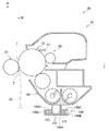
 document conveying device 40, the light source 44, the full rate mirror 46, the half rate mirror 48 and the half rate mirror 50 are stopped and the reading conveyed by the automatic document conveying device 40 is performed. The light source 44 irradiates the original G with light, and the reflected light reflected from the read original G forms an image on the photoelectric conversion element 54.

〔画像形成部〕
図12、図14に示されるように、画像形成部20は、像保持体56と、像保持体56の表面を帯電させる帯電部材58と、画像データに基づいて帯電した像保持体56の表面に露光光を照射して静電潜像を形成させる露光部材の一例としての露光装置60と、この静電潜像を現像してトナー画像として可視化する現像装置62とを備えている。
(Image forming part)
As shown in FIGS. 12 and 14, the image forming unit 20 includes an image carrier 56, a charging member 58 that charges the surface of the image carrier 56, and the surface of the image carrier 56 that is charged based on image data. Are provided with an exposure device 60 as an example of an exposure member that forms an electrostatic latent image by irradiating the exposure light, and a developing device 62 that develops the electrostatic latent image and visualizes it as a toner image.

さらに、画像形成部20は、搬送経路28に沿って搬送されるシート部材Pに像保持体56の表面に形成されたトナー画像を転写する転写ロール64と、加熱ロール66Hと加圧ロール66Nとから構成され、シート部材P上のトナー画像を加熱・加圧してシート部材Pに定着させる定着装置66と、トナー画像が転写された後の像保持体56に残留するトナーを像保持体56からかき落として像保持体56を清掃するクリーニングブレード68と備えている。   Further, the image forming unit 20 includes a transfer roll 64 that transfers the toner image formed on the surface of the image holding member 56 to the sheet member P conveyed along the conveyance path 28, a heating roll 66H, and a pressure roll 66N. And a fixing device 66 that heats and pressurizes the toner image on the sheet member P to fix the toner image on the sheet member P, and the toner remaining on the image carrier 56 after the toner image is transferred from the image carrier 56. A cleaning blade 68 is provided for cleaning the image carrier 56 by scraping.

さらに、露光装置60の斜め上方には、現像装置62と図示せぬ供給管で接続されたトナーカートリッジ72が配置されている。このトナーカートリッジ72には、供給管を介して現像装置62へ供給されるトナーが充填されている。   Further, a toner cartridge 72 connected to the developing device 62 via a supply pipe (not shown) is disposed obliquely above the exposure device 60. The toner cartridge 72 is filled with toner to be supplied to the developing device 62 through a supply pipe.

この構成において、位置合せロール36から送り出されたシート部材Pは、像保持体56と転写ロール64とで構成される転写位置Tへ搬送され、像保持体56と転写ロール64との間を挟持搬送される。これにより、シート部材Pに像保持体56に形成されたトナー画像がシート部材Pに転写されるようになっている。   In this configuration, the sheet member P fed from the alignment roll 36 is conveyed to a transfer position T constituted by the image holding body 56 and the transfer roll 64, and is sandwiched between the image holding body 56 and the transfer roll 64. Be transported. As a result, the toner image formed on the image carrier 56 on the sheet member P is transferred to the sheet member P.

ここで、像保持体56、帯電部材58、現像装置62及びクリーニングブレード68は、画像形成ユニット70を構成しており、この画像形成ユニット70は、装置本体10Aに対して着脱可能とされている。なお、画像形成ユニット70及び露光装置60を支持する支持構造等については、詳細を後述する。
(全体構成の作用)
前述した画像形成装置10では、次のようにして画像が形成される。
Here, the image holding member 56, the charging member 58, the developing device 62, and the cleaning blade 68 constitute an image forming unit 70, and the image forming unit 70 is detachable from the apparatus main body 10A. . Details of the support structure for supporting the image forming unit 70 and the exposure apparatus 60 will be described later.
(Operation of the overall configuration)
In the image forming apparatus 10 described above, an image is formed as follows.

まず、電圧が印加された帯電部材58は、像保持体56の表面を予定の電位で一様にマイナス帯電する。続いて、原稿読取部22によって読み取られた画像データ又は外部から入力されたデータに基づいて露光装置60が帯電された像保持体56の表面に露光光を照射して静電潜像を形成させる。   First, the charging member 58 to which a voltage is applied uniformly negatively charges the surface of the image carrier 56 with a predetermined potential. Subsequently, the exposure device 60 irradiates the surface of the image carrier 56 charged by the exposure device 60 based on image data read by the document reading unit 22 or data input from the outside to form an electrostatic latent image. .

これにより、画像データに対応した静電潜像が像保持体56の表面に形成される。さらに、この静電潜像は、現像装置62によって現像され、トナー画像として可視化される。   As a result, an electrostatic latent image corresponding to the image data is formed on the surface of the image carrier 56. Further, the electrostatic latent image is developed by the developing device 62 and visualized as a toner image.

そこで、収容部材26から送出ロール32によって搬送経路28へ送り出され、又は手差給紙部材92から給紙ロール94によって搬送経路28へ給紙されたシート部材Pが、位置合せロール36によって決められたタイミングで転写位置Tへ送り出される。転写位置Tでは、シート部材Pが像保持体56と転写ロール64とに挟持搬送されることで、像保持体56の表面に形成されたトナー画像がシート部材Pの表面に転写される。   Therefore, the sheet member P sent out from the storage member 26 to the transport path 28 by the sending roll 32 or fed from the manual sheet feeding member 92 to the transport path 28 is determined by the alignment roll 36. Sent to the transfer position T at the same timing. At the transfer position T, the sheet member P is nipped and conveyed between the image carrier 56 and the transfer roll 64, whereby the toner image formed on the surface of the image carrier 56 is transferred to the surface of the sheet member P.

シート部材Pに転写されたトナー画像は、シート部材Pが定着装置66に備えられた加熱ロール66Hと加圧ロール66Nとの間を通過することでシート部材Pに定着される。そして、表面にトナー画像が定着されたシート部材Pは、排出ロール76によって排出部74へ排出される。   The toner image transferred to the sheet member P is fixed to the sheet member P when the sheet member P passes between a heating roll 66H and a pressure roll 66N provided in the fixing device 66. Then, the sheet member P with the toner image fixed on the surface is discharged to the discharge portion 74 by the discharge roll 76.

一方、シート部材Pの裏面にも画像を形成させる場合には、シート部材Pを排出部74へ排出させずに排出ロール76を逆転させて、表面にトナー画像が形成されたシート部材Pを反転経路82へ送り出す。これにより、シート部材Pの表裏を反転させ、搬送ロール84がシート部材Pを再度位置合せロール36へ搬送する。   On the other hand, when an image is also formed on the back surface of the sheet member P, the discharge roller 76 is reversed without discharging the sheet member P to the discharge unit 74, and the sheet member P on which the toner image is formed is reversed. Send to path 82. As a result, the front and back of the sheet member P are reversed, and the transport roll 84 transports the sheet member P to the alignment roll 36 again.

今度は、転写位置Tでシート部材Pの裏面にトナー画像が転写され、裏面にトナー画像が転写されたシート部材Pは、前述した手順で排出部74へ排出される。
(要部構成)
次に、画像形成ユニット70及び露光装置60を支持する支持構造等について説明する。
This time, the toner image is transferred to the back surface of the sheet member P at the transfer position T, and the sheet member P on which the toner image is transferred to the back surface is discharged to the discharge unit 74 in the above-described procedure.
(Main part configuration)
Next, a support structure that supports the
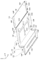
 image forming unit 70 and the exposure apparatus 60 will be described.

〔骨格部〕
装置本体10Aの骨格部材である骨格部100には、図5に示されるように、装置奥行方向における手前側に配置され、上下方向に延びる柱部材102が備えられている。この柱部材102は、装置幅方向の一端側(図に示す左端側)に配置された柱部材102Aと、他端側(図に示す右端側)に配置された柱部材102Bとを備えている。
[Skeleton]
As shown in FIG. 5, the skeleton part 100 that is a skeleton member of the apparatus main body 10 </ b> A includes a column member 102 that is disposed on the front side in the apparatus depth direction and extends in the vertical direction. The column member 102 includes a column member 102A disposed on one end side (left end side shown in the drawing) and a column member 102B arranged on the other end side (right end side shown in the drawing). .

柱部材102Aにおける水平方向の断面は、柱部材102Bにおける水平方向の断面より大きくされている。また、柱部材102Aの長さと柱部材102Bの長さとは同様とされ、柱部材102Aと柱部材102Bとの上端及び柱部材102Aと柱部材102Bとの下端は、同様の高さとされている。   The horizontal section of the column member 102A is larger than the horizontal section of the column member 102B. Further, the length of the column member 102A and the length of the column member 102B are the same, and the upper ends of the column member 102A and the column member 102B and the lower ends of the column member 102A and the column member 102B have the same height.

さらに、柱部材102Aと柱部材102Bとの間には、第一の側壁の一例としてのフロントプレート104が備えられている。   Further, a front plate 104 as an example of a first side wall is provided between the column member 102A and the column member 102B.

フロントプレート104は,装置奥行方向から見てほぼ矩形状とされ、板面が装置奥行方向に向くように配置されている。さらに、フロントプレート104の上下方向の長さは、柱部材102の長さの3分の1程度とされている。そして、フロントプレート104の柱部材102A側は、図示せぬスクリューを用いて柱部材102Aに固定され、フロントプレート104の柱部材102B側は、柱部材102Bを補強する補強部材114に固定され、柱部材102Bとは切り離された状態である。   The front plate 104 has a substantially rectangular shape when viewed from the apparatus depth direction, and is disposed such that the plate surface faces the apparatus depth direction. Furthermore, the length of the front plate 104 in the vertical direction is about one third of the length of the column member 102. The column member 102A side of the front plate 104 is fixed to the column member 102A using a screw (not shown), and the column member 102B side of the front plate 104 is fixed to the reinforcing member 114 that reinforces the column member 102B. It is in a state of being separated from the member 102B.

補強部材114は、上下方向に延びて備えられ、柱部材102Bに図示せぬスクリューを用いて固定されている。そして、補強部材114の上端の位置は、フロントプレート104の上端の位置と同等とされ、補強部材114の下端の位置は、柱部材102Bの下端の位置と同等とされている。   The reinforcing member 114 is provided so as to extend in the vertical direction, and is fixed to the column member 102B using a screw (not shown). The upper end position of the reinforcing member 114 is equivalent to the upper end position of the front plate 104, and the lower end position of the reinforcing member 114 is equivalent to the lower end position of the column member 102B.

また、フロントプレート104において、柱部材102A側には、画像形成ユニット70(図10参照)を装置本体10Aに着脱させる際に、画像形成ユニット70が通過する通過孔104Aが形成されている。   Further, in the front plate 104, a through hole 104A through which the image forming unit 70 passes when the image forming unit 70 (see FIG. 10) is attached to and detached from the apparatus main body 10A is formed on the column member 102A side.

さらに、フロントプレート104に対して装置奥行方向の奥側には、フロントプレート104と距離を空けて第二の側壁の一例としてのリアプレート106が配置されている。このように、リアプレート106はフロントプレート104に対向して配置されている。なお、本構成では、リアプレート106とフロントプレート104とが対向する対向方向は、装置奥行方向と同一方向とされている。   Further, a rear plate 106 as an example of a second side wall is disposed on the far side in the apparatus depth direction with respect to the front plate 104 at a distance from the front plate 104. Thus, the rear plate 106 is disposed so as to face the front plate 104. In this configuration, the facing direction in which the rear plate 106 and the front plate 104 face each other is the same direction as the apparatus depth direction.

リアプレート106は、装置幅方向に亘って備えられ、リアプレート106の上端と、柱部材102A及び柱部材102Bの上端とは、同様の高さとされている。さらに、リアプレート106の上下方向の長さは、柱部材102A及び柱部材102Bの長さと同等とされている。また、リアプレート106の装置幅方向の両端側には、装置奥側に折り曲げられたフランジ106Aが形成されている。   The rear plate 106 is provided in the apparatus width direction, and the upper end of the rear plate 106 and the upper ends of the column member 102A and the column member 102B have the same height. Furthermore, the length of the rear plate 106 in the vertical direction is equal to the length of the column member 102A and the column member 102B. Further, flanges 106A that are bent toward the back of the apparatus are formed on both ends of the rear plate 106 in the apparatus width direction.

さらに、柱部材102Aの上端と、リアプレート106の上端とを掛け渡すように、装置奥行方向に延びる梁部材108が備えられている。梁部材108の一端は、柱部材102Aの上端に図示せぬエンボス等で位置決めされ、図示せぬスクリューを用いて固定されている。また、梁部材108の他端は、リアプレート106の装置幅方向の左端側の上端に図示せぬエンボス等で位置決めされ、図示せぬスクリューを用いて固定されている。   Furthermore, a beam member 108 extending in the apparatus depth direction is provided so as to span the upper end of the column member 102A and the upper end of the rear plate 106. One end of the beam member 108 is positioned at the upper end of the column member 102A by an emboss or the like (not shown) and fixed using a screw (not shown). The other end of the beam member 108 is positioned at the upper end of the rear plate 106 on the left end side in the apparatus width direction by an emboss or the like (not shown) and fixed using a screw (not shown).

そして、梁部材108の上面に、原稿読取部22の読取装置本体22Aの一端側(図14に示す左側)が、位置決めされて図示せぬスクリューを用いて取り付けられるようになっている。   Then, one end side (left side shown in FIG. 14) of the reading device main body 22A of the document reading unit 22 is positioned and attached to the upper surface of the beam member 108 using a screw (not shown).

また、柱部材102Bの上端と、リアプレート106の上端とを掛け渡すように、装置奥行方向に延びる梁部材110が備えられている。そして、梁部材110の長手方向に対して直交する方向の断面は、梁部材108の長手方向に対して直交する方向の断面より小さくされている。さらに、梁部材110の一端は、柱部材102Bの上端に図示せぬスクリューを用いて固定され、梁部材110の他端は、リアプレート106の装置幅方向の右端側の上端に図示せぬスクリューを用いて固定されている。   Further, a beam member 110 extending in the apparatus depth direction is provided so as to span the upper end of the column member 102B and the upper end of the rear plate 106. The cross section in the direction orthogonal to the longitudinal direction of the beam member 110 is smaller than the cross section in the direction orthogonal to the longitudinal direction of the beam member 108. Further, one end of the beam member 110 is fixed to the upper end of the column member 102B using a screw (not shown), and the other end of the beam member 110 is screwed to the upper end of the rear plate 106 on the right end side in the apparatus width direction. It is fixed using.

そして、梁部材110の上面に、原稿読取部22の読取装置本体22Aの他端側(図14に示す右側)が、図示せぬスクリューで取り付けられるようになっている。   The other end side (the right side shown in FIG. 14) of the reading device main body 22A of the document reading unit 22 is attached to the upper surface of the beam member 110 with a screw (not shown).

さらに、柱部材102Aの下端側と、リアプレート106の下端側とを掛け渡すように、装置奥行方向に延びる梁部材112が備えられている。梁部材112の長手方向に対して直交する方向の断面は、装置内側が開放されたコ字形状とされている。   Furthermore, a beam member 112 extending in the apparatus depth direction is provided so as to span the lower end side of the column member 102A and the lower end side of the rear plate 106. A cross section in a direction orthogonal to the longitudinal direction of the beam member 112 has a U shape with the inside of the apparatus open.

また、梁部材112の一端は、柱部材102Aの下端側に図示せぬエンボス等で位置決めされ、図示せぬスクリューを用いて固定されている。さらに、梁部材112の他端は、リアプレート106の装置幅方向の左端側の下端側に図示せぬエンボス等で位置決めされ、図示せぬスクリューを用いて固定されている。   Further, one end of the beam member 112 is positioned on the lower end side of the column member 102A by an embossing or the like (not shown) and fixed using a screw (not shown). Furthermore, the other end of the beam member 112 is positioned by a not-shown emboss or the like on the lower end of the rear plate 106 on the left end side in the apparatus width direction, and is fixed using a screw (not shown).

また、柱部材102B及び補強部材114の下端側と、リアプレート106の下端側とを掛け渡すように、装置奥行方向に延びる梁部材116が備えられている。梁部材116の長手方向に対して直交する方向の断面は、装置内側が開放されたコ字形状とされ、梁部材112の断面と比して上下方向の長さが長くされている。   Further, a beam member 116 extending in the apparatus depth direction is provided so as to span the lower end side of the column member 102B and the reinforcing member 114 and the lower end side of the rear plate 106. The cross section in the direction orthogonal to the longitudinal direction of the beam member 116 is a U-shape in which the inside of the apparatus is opened, and the length in the vertical direction is longer than the cross section of the beam member 112.

さらに、梁部材116の一端は、補強部材114の下端側に図示せぬエンボス等で位置決めされ、図示せぬスクリューを用いて固定されている。また、梁部材116の他端は、リアプレート106の装置幅方向の右端側の下端側に図示せぬエンボス等で位置決めされ、図示せぬスクリューを用いて固定されている。   Furthermore, one end of the beam member 116 is positioned on the lower end side of the reinforcing member 114 by an embossing or the like (not shown) and is fixed using a screw (not shown). The other end of the beam member 116 is positioned by a not shown embossing or the like on the lower end side of the rear plate 106 on the right end side in the apparatus width direction, and is fixed using a screw not shown.

また、補強部材114の下端側と、柱部材102Aの下端側とを掛け渡すように、装置幅方向に延びる梁部材118が備えられている。梁部材118の一端は、補強部材114の下端側に図示せぬエンボス等で位置決めされ、図示せぬスクリューを用いて固定されている。また、梁部材118の他端は、柱部材102Aの下端側に図示せぬエンボス等で位置決めされ、図示せぬスクリューを用いて固定されている。   Further, a beam member 118 extending in the apparatus width direction is provided so as to span the lower end side of the reinforcing member 114 and the lower end side of the column member 102A. One end of the beam member 118 is positioned on the lower end side of the reinforcing member 114 by an emboss (not shown) or the like, and is fixed using a screw (not shown). Further, the other end of the beam member 118 is positioned on the lower end side of the column member 102A by an embossing (not shown) or the like, and is fixed using a screw (not shown).

この梁部材118の上側で、梁部材116と梁部材112との間に、前述した収容部材26(図13参照)が配置されるようになっている。   On the upper side of the beam member 118, the accommodating member 26 (see FIG. 13) described above is arranged between the beam member 116 and the beam member 112.

一方、リアプレート106に対して装置奥行方向の手前側は、図2、図5に示されるように、前述した露光装置60、画像形成ユニット70及び図示せぬ配電基板等が配置される第一空間の一例としての画像形成空間120と、シート部材Pが積載される収容部材26が配置される第二空間の一例としての記録媒体空間122とされている。   On the other hand, on the near side in the apparatus depth direction with respect to the rear plate 106, as shown in FIGS. 2 and 5, the first exposure apparatus 60, the image forming unit 70, the power distribution board (not shown), and the like are arranged. An image forming space 120 as an example of a space and a recording medium space 122 as an example of a second space in which the accommodating member 26 on which the sheet members P are stacked are arranged.

さらに、フロントプレート104とリアプレート106との間には、画像形成空間120と記録媒体空間122とに空間全体の少なくとも一部を仕切る板状の第一仕切り部材128と、第一仕切り部材128に対して図中右側に配置され、画像形成空間120と記録媒体空間122とに空間全体の少なくとも他の一部を仕切る板状の第二仕切り部材130とが備えられている。   Further, between the front plate 104 and the rear plate 106, a plate-like first partition member 128 that partitions at least a part of the entire space into an image forming space 120 and a recording medium space 122, and a first partition member 128 On the other hand, a plate-shaped second partition member 130 that is disposed on the right side in the drawing and partitions at least another part of the entire space into the image forming space 120 and the recording medium space 122 is provided.

そして、装置奥行方向(対向方向)から見て、骨格部100(装置本体10A)の装置幅方向の一端側から他端側にかけて、画像形成空間120と記録媒体空間122とに、第一仕切り部材128及び第二仕切り部材130によって仕切られている。   Then, when viewed from the apparatus depth direction (opposite direction), the first partition member is formed between the
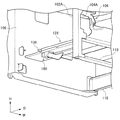
 image forming space 120 and the recording medium space 122 from one end side to the other end side in the apparatus width direction of the skeleton 100 (apparatus main body 10A). 128 and the second partition member 130.

[第一仕切り部材]
具体的には、第一仕切り部材128は、例えば板厚1.0〔mm〕の鋼板から形成され、フロントプレート104とリアプレート106との間で、フロントプレート104とリアプレート106とが対向する奥行方向に延びて配置されている。
[First partition member]
Specifically, the first partition member 128 is formed of, for example, a steel plate having a thickness of 1.0 [mm], and the front plate 104 and the rear plate 106 face each other between the front plate 104 and the rear plate 106. It is arranged extending in the depth direction.

図3に示されるように、第一仕切り部材128は、板部材を折り曲げて形成され、第二仕切り部材130の隣りに配置され、板面が上下方向を向いた他の補強板の一例としての第一水平板134を備えている。   As shown in FIG. 3, the first partition member 128 is formed by bending a plate member, is disposed next to the second partition member 130, and serves as an example of another reinforcing plate whose plate surface faces in the vertical direction. A first horizontal plate 134 is provided.

さらに、第一仕切り部材128は、第一水平板134において第二仕切り部材130に対して反対側の縁部が下方に折り曲げて形成され、板面が装置幅方向を向いた第一補強板の一例としての垂直板136を備えている。また、第一仕切り部材128は、垂直板136の下端側が第一水平板134に対して反対側に折り曲げられ、板面が上下方向を向いた第二補強板の一例としての第二水平板138を備えている。   Further, the first partition member 128 is formed by bending the edge of the first horizontal plate 134 opposite to the second partition member 130 downward, and the plate surface faces the device width direction. As an example, a vertical plate 136 is provided. The first partition member 128 has a second horizontal plate 138 as an example of a second reinforcing plate in which the lower end side of the vertical plate 136 is bent to the opposite side with respect to the first horizontal plate 134 and the plate surface faces the vertical direction. It has.

このように、第一仕切り部材128は、第一水平板134、垂直板136及び第二水平板138を含んで階段状に構成され、第一仕切り部材128の外周には、端部が折り曲げられることでフランジ134F、136F、138Fが形成されている。そして、装置奥行方向から見て、第一水平板134と垂直板136とでL字状とされるL字部位132が構成され、垂直板136と第二水平板138とでL字状とされるL字部位140が構成されている。   As described above, the first partition member 128 is configured in a stepped manner including the first horizontal plate 134, the vertical plate 136, and the second horizontal plate 138, and an end portion is bent on the outer periphery of the first partition member 128. Thus, flanges 134F, 136F, and 138F are formed. When viewed from the depth direction of the apparatus, the first horizontal plate 134 and the vertical plate 136 constitute an L-shaped portion 132 that is L-shaped, and the vertical plate 136 and the second horizontal plate 138 are L-shaped. The L-shaped portion 140 is configured.

ここで、L字状とは、一の線分と、一の線分の端部に連結される他の線分とから構成され、一の線分と他の線分との成す角度が、0度より大きく180度より小さい形状である。そして、一の線分と他の線分とで構成される角にはRが形成されていてもよい。   Here, the L-shape is composed of one line segment and another line segment connected to the end of the one line segment, and the angle formed by the one line segment and the other line segment is The shape is larger than 0 degree and smaller than 180 degrees. And R may be formed in the corner comprised by one line segment and other line segments.

また、第一水平板134において装置奥行方向の両端には、夫々一対の爪部134Aがフランジ134Fから切り起こされることで形成されている。さらに、第一水平板134の板面には、装置幅方向に間隔を空けて、位置決め用のデータム孔134B、134Cが形成されている。   Further, a pair of claw portions 134A are formed by cutting and raising from the flange 134F at both ends of the first horizontal plate 134 in the apparatus depth direction. Further, datum holes 134B and 134C for positioning are formed on the plate surface of the first horizontal plate 134 with an interval in the apparatus width direction.

この第一水平板134の上面には、露光装置60が取り付けられるようになっている。そして、露光装置60が第一水平板134に取り付けられた状態で、図6に示されるように、データム孔134B、134Cが、露光装置60に覆われるようになっている。   An exposure device 60 is attached to the upper surface of the first horizontal plate 134. Then, with the exposure apparatus 60 attached to the first horizontal plate 134, the datum holes 134B and 134C are covered with the exposure apparatus 60 as shown in FIG.

また、図3に示されるように、第一水平板134及び第二水平板138の板面には、凹状のビード134D、138Dが形成されており、露光装置60を稼動させた際に、第一仕切り部材128が、露光装置60等によって生じる振動と共振しないようになっている。   Also, as shown in FIG. 3, concave beads 134D and 138D are formed on the plate surfaces of the first horizontal plate 134 and the second horizontal plate 138. When the exposure apparatus 60 is operated, the first bead 134D and 138D are formed. The one partition member 128 does not resonate with vibration generated by the exposure apparatus 60 or the like.

さらに、第二水平板138の下面には、図11に示されるように、収容部材26に積載される最上位のシート部材Pと自由端で当たってシート部材Pの残紙量を検知する揺動タイプの残紙センサ160が取り付けられている。また、第二水平板138の下面には、装置本体10Aに装着される収容部材26と当たって収容部材26(図14参照)の装着位置を決める図示せぬ位置決め部材が取り付けられている。   Further, as shown in FIG. 11, the lower surface of the second horizontal plate 138 abuts against the uppermost sheet member P stacked on the storage member 26 at the free end to detect the remaining amount of the sheet member P. A moving type residual paper sensor 160 is attached. In addition, a positioning member (not shown) is attached to the lower surface of the second horizontal plate 138 to come into contact with the housing member 26 mounted on the apparatus main body 10A and determines the mounting position of the housing member 26 (see FIG. 14).

図3、図5に示されるように、この構成において、第一仕切り部材128を、フロントプレート104及びリアプレート106に組み付ける際には、第一水平板134に形成されたデータム孔134B、134Cに図示せぬ位置決めピンを挿入する。また、第一水平板134の板面を図示せぬ位置決め冶具に当てることで第一水平板134を位置決めする。   As shown in FIGS. 3 and 5, in this configuration, when the first partition member 128 is assembled to the front plate 104 and the rear plate 106, the datum holes 134 </ b> B and 134 </ b> C formed in the first horizontal plate 134 are formed. Insert a positioning pin (not shown). Further, the first horizontal plate 134 is positioned by applying the plate surface of the first horizontal plate 134 to a positioning jig (not shown).

さらに、爪部134Aを、フロントプレート104及びリアプレート106に形成された開口孔104B,106Bに差し込む。そして、第一水平板134、垂直板136及び第二水平板138に形成されたフランジ134F、136F、138Fを、フロントプレート104及びリアプレート106に図示せぬスクリューを用いて固定されるようになっている。この組み付け工程から理解できるように、第一水平板134の位置精度は、垂直板136及び第二水平板138の位置精度に比して高くされている。   Further, the claw portion 134A is inserted into the opening holes 104B and 106B formed in the front plate 104 and the rear plate 106. The flanges 134F, 136F, and 138F formed on the first horizontal plate 134, the vertical plate 136, and the second horizontal plate 138 are fixed to the front plate 104 and the rear plate 106 using screws (not shown). ing. As can be understood from this assembly process, the positional accuracy of the first horizontal plate 134 is higher than the positional accuracy of the vertical plate 136 and the second horizontal plate 138.

[第二仕切り部材]
これに対して、第一仕切り部材128の隣りに隙間(例えば5〔mm〕)を空けて配置される第二仕切り部材130は、例えば板厚0.8〔mm〕の鋼板から形成され、フロントプレート104とリアプレート106との間で、奥行方向に延びて配置されている。
[Second partition member]
On the other hand, the second partition member 130 disposed with a gap (for example, 5 mm) adjacent to the first partition member 128 is formed of a steel plate having a thickness of 0.8 [mm], for example, Between the plate 104 and the rear plate 106, it extends in the depth direction.

第二仕切り部材130は、板面が上下方向を向いた水平板142を備えている。水平板142の板面には、ビードが形成されておらず、水平板142の外周には、端部が折り曲げられることでフランジ142Fが形成されている。さらに、水平板142において装置奥行方向の手前側の端部には、一対の爪部142Aがフランジ142Fから切り起こされることで形成されている。   The second partition member 130 includes a horizontal plate 142 whose plate surface faces in the vertical direction. A bead is not formed on the plate surface of the horizontal plate 142, and a flange 142F is formed on the outer periphery of the horizontal plate 142 by bending an end. Further, a pair of claw portions 142A are formed by cutting and raising from the flange 142F at the front end of the horizontal plate 142 in the apparatus depth direction.

また、第二仕切り部材130において、画像形成空間120から記録媒体空間122へ向かう仕切り方向(本構成では、上下方向と同一方向)における曲げ剛性は、第一仕切り部材128における上下方向の剛性に比して低くされている。   In the second partition member 130, the bending rigidity in the partition direction from the image forming space 120 to the recording medium space 122 (in this configuration, the same direction as the vertical direction) is higher than the rigidity in the vertical direction of the first partition member 128. And it is low.

この構成において、第二仕切り部材130を、フロントプレート104及びリアプレート106に組み付ける際には、爪部142Aを、フロントプレート104に形成された開口孔104Bに差し込む。そして、フランジ142Fを、フロントプレート104及びリアプレート106に図示せぬスクリューを用いて固定されるようになっている。   In this configuration, when the second partition member 130 is assembled to the front plate 104 and the rear plate 106, the claw portion 142 </ b> A is inserted into the opening hole 104 </ b> B formed in the front plate 104. The flange 142F is fixed to the front plate 104 and the rear plate 106 using screws (not shown).

ここで、第二仕切り部材130のフロントプレート104及びリアプレート106への固定は、第一仕切り部材128のフロントプレート104及びリアプレート106への固定後に行われるようになっている。   Here, the second partition member 130 is fixed to the front plate 104 and the rear plate 106 after the first partition member 128 is fixed to the front plate 104 and the rear plate 106.

前述したように、上下方向における第二仕切り部材130の剛性は、第一仕切り部材128の剛性に比して低くされている。このため、仮に第二仕切り部材130の固定位置が正規の位置に対してずれてしまった場合でも、既に固定されている第一仕切り部材128を変位させることなく、第二仕切り部材130が変形することでフロントプレート104及びリアプレート106に固定されるようになっている。なお、第二仕切り部材130の固定位置が正規の位置に対してずれている場合には、第二仕切り部材130が変形するように、第二仕切り部材130の寸法公差等が決められている。   As described above, the rigidity of the second partition member 130 in the vertical direction is lower than the rigidity of the first partition member 128. For this reason, even if the fixing position of the second partition member 130 is shifted from the normal position, the second partition member 130 is deformed without displacing the already-fixed first partition member 128. As a result, the front plate 104 and the rear plate 106 are fixed. In addition, when the fixed position of the 2nd partition member 130 has shifted | deviated with respect to the regular position, the dimensional tolerance etc. of the 2nd partition member 130 are determined so that the 2nd partition member 130 may deform | transform.

このように第二仕切り部材130が変形する場合には、フロントプレート104及びリアプレート106において、第二仕切り部材130が固定される部分が変位する。これにより、補強部材114によって補強されていない柱部材102Aの上側部分が変位する。さらに、柱部材102Aの上側部分が変位することで、梁部材110も変位するようになっている。すなわち、前述した部位以外の部位は、第二仕切り部材130の変形による影響が少ない構成となっている。   Thus, when the 2nd partition member 130 deform | transforms, the part to which the 2nd partition member 130 is fixed in the front plate 104 and the rear plate 106 is displaced. As a result, the upper portion of the column member 102A that is not reinforced by the reinforcing member 114 is displaced. Furthermore, when the upper part of the column member 102A is displaced, the beam member 110 is also displaced. In other words, the parts other than the parts described above are less affected by the deformation of the second partition member 130.

また、このように梁部材110が変位することがあるため、読取装置本体22Aは、前述したように梁部材108を基準に骨格部100に取り付けられるようになっている。   Further, since the beam member 110 may be displaced in this way, the reader main body 22A is attached to the skeleton part 100 with the beam member 108 as a reference as described above.

[支持部材]
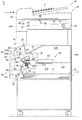
次に、画像形成ユニット70を支持する支持部材146について説明する。
[Support member]
Next, the support member 146 that supports the image forming unit 70 will be described.

図4、図8に示されるように、支持部材146は、例えば樹脂材料にて成形されており、装置奥行方向に延びている。装置奥行方向(長手方向)の一端がフロントプレート104に図示せぬスクリューで取り付けられ、装置奥行方向(長手方向)の他端がリアプレート106に図示せぬスクリューで取り付けられるようになっている。   As shown in FIGS. 4 and 8, the support member 146 is formed of, for example, a resin material and extends in the apparatus depth direction. One end in the apparatus depth direction (longitudinal direction) is attached to the front plate 104 with a screw (not shown), and the other end in the apparatus depth direction (longitudinal direction) is attached to the rear plate 106 with a screw (not shown).

具体的には、支持部材146は、装置奥行方向に延びて画像形成ユニット70を支持する支持部位148と、フロントプレート104に取り付けられる取付部位150と、リアプレート106に取り付けられる取付部位152とを備えている。   Specifically, the support member 146 includes a support part 148 that extends in the apparatus depth direction and supports the image forming unit 70, an attachment part 150 that is attached to the front plate 104, and an attachment part 152 that is attached to the rear plate 106. I have.

支持部位148は、底板148Aと、底板148Aの幅方向の両端から立ち上がる一対の側板148Bとを備えている。さらに、一対の側板148Bの上端には、上方から見て千鳥状に配置され、互いに幅方向の内側に向けて突出し、装置奥行方向から見て対向する先端が離間する複数の突出板148Cが備えられている。   The support portion 148 includes a bottom plate 148A and a pair of side plates 148B that rise from both ends of the bottom plate 148A in the width direction. Furthermore, the upper ends of the pair of side plates 148B are provided with a plurality of projecting plates 148C that are arranged in a staggered manner when viewed from above, project toward the inner side in the width direction, and are spaced apart from each other when viewed from the depth direction of the device. It has been.

支持部位148は、底板148Aと、一対の側板148Bと、複数の突出板148Cとを含んで構成され、装置奥行方向から見て、上方が開放されたチャンネル形状(C型形状)とされている(図1参照)。   The support portion 148 includes a bottom plate 148A, a pair of side plates 148B, and a plurality of projecting plates 148C, and has a channel shape (C shape) with an upper portion opened when viewed from the depth direction of the apparatus. (See FIG. 1).

一方、フロントプレート104に取り付けられる取付部位150は、底板148Aの一端から下方に向けて延び、装置奥行方向に板面が向いた板状とされている。さらに、装置奥行方向から見て、装置幅方向における取付部位150の中央側には、上下方向に延びる貫通孔150Aが形成され、貫通孔150Aの両側には、貫通孔150Aよりも上下方向に長く延びる一対の貫通孔150Bが形成されている。   On the other hand, the attachment portion 150 attached to the front plate 104 has a plate shape extending downward from one end of the bottom plate 148A and having a plate surface facing in the depth direction of the apparatus. Furthermore, as viewed from the depth direction of the apparatus, a through hole 150A extending in the vertical direction is formed on the center side of the attachment site 150 in the apparatus width direction, and on both sides of the through hole 150A, it is longer in the vertical direction than the through hole 150A. A pair of extending through holes 150B are formed.

これに対して、リアプレート106に取り付けられる取付部位152も、取付部位150と同様の形状とされている。取付部位152は、装置幅方向における中央側に配置された貫通孔152Aと、その両側に配置された一対の貫通孔152Bとを備えている。そして、装置奥行方向から見て、取付部位152の外周縁と取付部位150の外周縁とは重なるようになっている(図1参照)。   On the other hand, the attachment part 152 attached to the rear plate 106 has the same shape as the attachment part 150. The attachment portion 152 includes a through hole 152A disposed on the center side in the apparatus width direction and a pair of through holes 152B disposed on both sides thereof. And the outer periphery of the attachment part 152 and the outer periphery of the attachment part 150 overlap so that it may see from an apparatus depth direction (refer FIG. 1).

この構成において、支持部材146を、フロントプレート104及びリアプレート106に取り付ける際には、図4、図6に示されるように、支持部材146の装置奥行方向の手前側を通過孔104Aの下端へ引っ掛け、取付部位150をフロントプレート104の板面に当てる。そして、図示せぬエンボス等を用いて、取付部位150をフロントプレート104に対して位置決めするようになっている。   In this configuration, when the support member 146 is attached to the front plate 104 and the rear plate 106, as shown in FIGS. 4 and 6, the front side of the support member 146 in the apparatus depth direction is directed to the lower end of the passage hole 104A. Hook the mounting part 150 against the plate surface of the front plate 104. And the attachment site | part 150 is positioned with respect to the front plate 104 using the embossing etc. which are not shown in figure.

これに対して、支持部材146の装置奥行方向の奥側については、取付部位152をリアプレート106の板面に当て、図示せぬエンボス等を用いて、取付部位152をリアプレート106に対して位置決めするようになっている。この状態で、支持部材146は、第一仕切り部材128と離間している。   On the other hand, with respect to the depth side of the support member 146 in the apparatus depth direction, the attachment portion 152 is applied to the plate surface of the rear plate 106 and the attachment portion 152 is attached to the rear plate 106 by using an emboss (not shown). It is designed to be positioned. In this state, the support member 146 is separated from the first partition member 128.

さらに、貫通孔150A、152Aに図示せぬスクリューを通して、取付部位150及び取付部位152を、フロントプレート104及びリアプレート106に取り付けるようになっている。そして、取付部位150、152において、フロントプレート104及びリアプレート106に取り付けられる取付範囲150C、152Cは、貫通孔150A、152Aの周辺範囲(図で示す斜線範囲)である。   Further, the attachment part 150 and the attachment part 152 are attached to the front plate 104 and the rear plate 106 through screws (not shown) through the through holes 150A and 152A. In the attachment portions 150 and 152, the attachment ranges 150C and 152C attached to the front plate 104 and the rear plate 106 are the peripheral ranges of the through holes 150A and 152A (shaded areas shown in the drawing).

ここで、図1に示されるように、取付範囲150C、152Cの少なくとも一部(本構成では全部)は、装置奥行方向から見て、フロントプレート104及びリアプレート106がL字部位140によって補強された補強範囲162に配置されている。   Here, as shown in FIG. 1, at least a part (all in this configuration) of the attachment ranges 150 </ b> C and 152 </ b> C is reinforced by the L-shaped portion 140 when viewed from the depth direction of the apparatus. The reinforcing range 162 is arranged.

具体的には、L字部位140によってフロントプレート104及びリアプレート106が補強される補強範囲162は、装置奥行方向から見て、垂直板136の縁部と長さ及び傾きが同様の線分Fを、第二水平板138の自由端を基端とし記載する。さらに、線分Fの先端と、垂直板136の上端とを結んで線分Eとする。   Specifically, the reinforcement range 162 in which the front plate 104 and the rear plate 106 are reinforced by the L-shaped portion 140 is a line segment F having the same length and inclination as the edge of the vertical plate 136 when viewed from the depth direction of the apparatus. Is described with the free end of the second horizontal plate 138 as the base end. Further, the tip of the line segment F and the upper end of the vertical plate 136 are connected to form a line segment E.

装置奥行方向から見て、この線分F、線分E及びL字部位140に囲まれた範囲(図に示す斜線範囲)は、L字部位140によって補強される部位であるため、これを補強範囲162とする。そして、本構成では、装置奥行方向から見て、この補強範囲162に、取付範囲150C、152Cの少なくとも一部が配置されている。   When viewed from the depth direction of the apparatus, the range surrounded by the line segment F, line segment E, and L-shaped part 140 (the hatched area shown in the figure) is a part reinforced by the L-shaped part 140, so that it is reinforced. The range 162 is assumed. In this configuration, when viewed from the depth direction of the apparatus, at least a part of the attachment ranges 150C and 152C is disposed in the reinforcing range 162.

〔画像形成ユニット〕
一方、図9に示されるように、画像形成ユニット70のユニット本体70Aの下面には、装置奥行方向に延びる2枚のガイド板156が形成されている。また、ガイド板156において、装置奥行方向の奥側には、ガイド板156の下端から装置幅方向の外側に突出する抜止板158がガイド板156と一体的に形成されている。
[Image forming unit]
On the other hand, as shown in FIG. 9, two guide plates 156 extending in the apparatus depth direction are formed on the lower surface of the unit main body 70 </ b> A of the image forming unit 70. In the guide plate 156, a retaining plate 158 that protrudes outward from the lower end of the guide plate 156 in the device width direction is formed integrally with the guide plate 156 on the back side in the device depth direction.

この構成において、画像形成ユニット70を装置本体10Aに装着させる際には、図示せぬメンテナンスカバーを開放し、画像形成ユニット70を、通過孔104Aを通過させながら装置奥行方向の奥側に移動させる。そして、図12に示されるように、画像形成ユニット70のガイド板156を支持部位148に挿入させながら画像形成ユニット70を装置奥行方向の奥側に押し込む。これにより、ガイド板156と図示せぬ位置決め部材とが当たって画像形成ユニット70が装置本体10Aに装着されるようになっている(図7参照)。この状態で、画像形成ユニット70を上方に移動させようとすると、抜止板158が、突出板148Cに当たって画像形成ユニット70の上方への移動が阻止されるようになっている。   In this configuration, when attaching the image forming unit 70 to the apparatus main body 10A, a maintenance cover (not shown) is opened, and the image forming unit 70 is moved to the back side in the apparatus depth direction while passing through the passage hole 104A. . Then, as shown in FIG. 12, the image forming unit 70 is pushed inward in the apparatus depth direction while the guide plate 156 of the image forming unit 70 is inserted into the support portion 148. As a result, the guide plate 156 and a positioning member (not shown) abut against each other so that the image forming unit 70 is attached to the apparatus main body 10A (see FIG. 7). If the image forming unit 70 is to be moved upward in this state, the retaining plate 158 hits the protruding plate 148C so that the image forming unit 70 is prevented from moving upward.

一方、画像形成ユニット70を装置本体10Aから離脱させる際には、図示せぬメンテナンスカバーを開放し、画像形成ユニット70を装置奥行方向の手前側に引き出す。これにより、画像形成ユニット70が装置本体10Aから離脱されるようになっている(図6、図10参照)。
(要部構成の作用)
次に、要部構成の作用について説明する。
On the other hand, when the image forming unit 70 is detached from the apparatus main body 10A, a maintenance cover (not shown) is opened, and the image forming unit 70 is pulled out to the near side in the apparatus depth direction. As a result, the image forming unit 70 is detached from the apparatus main body 10A (see FIGS. 6 and 10).
(Effects of main components)
Next, the operation of the main configuration will be described.

前述したように、第二仕切り部材130における上下方向の剛性は、第一仕切り部材128における上下方向の剛性に比して低くされている。このため、仮に第二仕切り部材130の取り付け位置及び第二仕切り部材130の形状がばらついた場合でも、既に取り付けられている第一仕切り部材128を変位させることなく、第二仕切り部材130が変形(塑性変形)することで第二仕切り部材130がフロントプレート104及びリアプレート106に取り付けられる。このように、第一仕切り部材128の変位を抑制させることで、第一仕切り板128に取り付けられる露光装置60が、第一仕切り部材128の変形によって変位するのが抑制される。また、例えば、画像形成装置10を搬送中に第二仕切り板130側から荷重が画像形成装置10に入力された場合に、第二仕切り部材130が変形することでエネルギーが吸収されるため、露光装置60が、第一仕切り部材128の変形によって変位するのが抑制される。   As described above, the vertical rigidity of the second partition member 130 is lower than the vertical rigidity of the first partition member 128. For this reason, even if the mounting position of the second partition member 130 and the shape of the second partition member 130 vary, the second partition member 130 is deformed without displacing the already-attached first partition member 128 ( The second partition member 130 is attached to the front plate 104 and the rear plate 106 by plastic deformation. In this way, by suppressing the displacement of the first partition member 128, the exposure device 60 attached to the first partition plate 128 is suppressed from being displaced by the deformation of the first partition member 128. Further, for example, when a load is input from the second partition plate 130 side to the image forming apparatus 10 while the image forming apparatus 10 is being conveyed, the energy is absorbed by the deformation of the second partition member 130, so that exposure is performed. Displacement of the device 60 due to deformation of the first partition member 128 is suppressed.

また、露光装置60の変位が抑制されることで、露光装置60の変位が抑制されない場合と比して、露光装置60から出射される露光光の照射位置精度が向上する。このため、像保持体56に形成される静電潜像の位置精度が向上する。   Moreover, by suppressing the displacement of the exposure apparatus 60, the irradiation position accuracy of the exposure light emitted from the exposure apparatus 60 is improved as compared with the case where the displacement of the exposure apparatus 60 is not suppressed. For this reason, the positional accuracy of the electrostatic latent image formed on the image carrier 56 is improved.

また、第一仕切り板128は、第一水平板134と垂直板136とで構成されるL字部位132を備えている。このため、第一仕切り板が平板状である場合と比して、第一仕切り部材128の変位が抑制される。   Further, the first partition plate 128 includes an L-shaped portion 132 composed of a first horizontal plate 134 and a vertical plate 136. For this reason, the displacement of the 1st partition member 128 is suppressed compared with the case where a 1st partition plate is flat form.

また、装置本体10Aの装置幅方向の一端側から他端側にかけて、第一仕切り部材128及び第二仕切り部材130が、空間を画像形成空間120と記録媒体空間122とに仕切っている。このため、記録媒体空間122から挿入されたユーザの手が画像形成空間120に侵入されるのが抑制される。さらに、画像形成ユニット70等から落下したトナーが、記録媒体空間122に侵入するのが抑制される。そして、エンクロージャ効果(発火対策)にも有効である。   Further, the first partition member 128 and the second partition member 130 partition the space into the image forming space 120 and the recording medium space 122 from one end side to the other end side in the apparatus width direction of the apparatus main body 10A. For this reason, the user's hand inserted from the recording medium space 122 is prevented from entering the image forming space 120. Further, toner that has fallen from the image forming unit 70 or the like is prevented from entering the recording medium space 122. It is also effective for the enclosure effect (fire prevention measures).

なお、本発明を特定の実施形態について詳細に説明したが、本発明は係る実施形態に限定されるものではなく、本発明の範囲内にて他の種々の実施形態が可能であることは当業者にとって明らかである。例えば、上記実施形態では、本構成を電子写真方式の画像形成装置を用いて説明したが、本構成をインクジェット方式等の画像形成装置に用いてもよい。   Although the present invention has been described in detail with respect to specific embodiments, the present invention is not limited to such embodiments, and various other embodiments are possible within the scope of the present invention. It is clear to the contractor. For example, in the above-described embodiment, the present configuration has been described using an electrophotographic image forming apparatus. However, the present configuration may be used for an image forming apparatus such as an inkjet method.

また、上記実施形態では、支持部材146をフロントプレート104及びリアプレート106に直接取り付けたが、装置奥行方向に延びるデスタンスピース等を介して支持部材146をフロントプレート104及びリアプレート106に取り付けてもよい。   In the above embodiment, the support member 146 is directly attached to the front plate 104 and the rear plate 106. However, the support member 146 is attached to the front plate 104 and the rear plate 106 via a distance piece that extends in the depth direction of the apparatus. Also good.

10 画像形成装置
20 画像形成部
56 像保持体
60 露光装置(露光部材の一例)
104 フロントプレート(第一の側壁の一例)
106 リアプレート(第二の側壁の一例)
120 画像形成空間(第一空間の一例)
122 記録媒体空間(第二空間の一例)
128 第一仕切り部材
130 第二仕切り板
132 L字部位
DESCRIPTION OF SYMBOLS 10 Image forming apparatus 20 Image forming part 56 Image holding body 60 Exposure apparatus (an example of exposure member)
104 Front plate (example of first side wall)
106 Rear plate (example of second side wall)
120 Image formation space (example of first space)
122 Recording medium space (example of second space)
128 First partition member 130 Second partition plate 132 L-shaped part

Claims (3)

像保持体と、前記像保持体の表面に露光光を照射して静電潜像を形成させる露光部材とを備える画像形成部と、
前記画像形成部の一側面側に設けられた第一の側壁と、
前記画像形成部を挟んで前記第一の側壁と対向するように、当該画像形成部に対して前記第一の側壁側とは反対側の側面側に設けられた第二の側壁と、
一端が前記第一の側壁に固定されると共に他端が前記第二の側壁に固定され、前記第一の側壁と前記第二の側壁とに挟まれた空間の一部を第一空間および第二空間とに仕切る第一仕切り部材と、
一端が前記第一の側壁に固定されると共に他端が前記第二の側壁に固定され、前記第一の側壁と前記第二の側壁とに挟まれた空間の一部を前記第一空間および前記第二空間とに仕切る第二仕切り部材と、
を備え、
前記第一仕切り部材および前記第二仕切り部材は、前記第一の側壁と前記第二の側壁とに挟まれた空間内の夫々異なる領域を前記第一空間および前記第二空間とに仕切るよう構成されており、
前記第一仕切り部材には、前記像保持体及び前記露光部材の少なくとも一方が取り付けられ、
前記第二仕切り部材の前記第一空間から前記第二空間へ向かう仕切り方向における剛性が前記第一仕切り部材の仕切り方向における剛性に対して低くされたことを特徴とする画像形成装置。
An image forming unit comprising: an image carrier; and an exposure member that irradiates the surface of the image carrier with exposure light to form an electrostatic latent image;
A first side wall provided on one side of the image forming unit;
A second side wall provided on a side surface opposite to the first side wall side with respect to the image forming unit so as to face the first side wall across the image forming unit;
One end is fixed to the first side wall and the other end is fixed to the second side wall, and a part of the space sandwiched between the first side wall and the second side wall is defined as the first space and the second side wall . A first partition member that partitions into two spaces;
One end is fixed to the first side wall and the other end is fixed to the second side wall, and a part of the space sandwiched between the first side wall and the second side wall is defined as the first space and A second partition member partitioning into the second space;
With
The first partition member and the second partition member are configured to partition different regions in a space sandwiched between the first side wall and the second side wall into the first space and the second space, respectively. Has been
At least one of the image carrier and the exposure member is attached to the first partition member,
2. An image forming apparatus according to claim 1, wherein the rigidity of the second partition member in the partition direction from the first space toward the second space is lower than the rigidity of the first partition member in the partition direction.
前記第一仕切り部材は、一端が前記第一の側壁に固定され、他端が前記第二の側壁に固定され、前記第一の側壁と前記第二の側壁とが対向する対向方向から見てL字状とされたL字部位を備えている請求項1に記載の画像形成装置。 One end of the first partition member is fixed to the first side wall , the other end is fixed to the second side wall, and the first side wall and the second side wall are viewed from opposite directions. The image forming apparatus according to claim 1, further comprising an L-shaped portion that is L-shaped. 前記第一空間には、画像を形成するのに用いられる前記像保持体及び前記露光部材が配置され、前記第二空間には、前記第一空間に送られて画像が記録される記録媒体が積載され、
前記第一の側壁と前記第二の側壁とが対向する対向方向から見て、装置本体の幅方向の一端側から他端側にかけて、前記第一空間と前記第二空間とが、前記第一仕切り部材及び前記第二仕切り部材によって仕切られた請求項1又は2に記載の画像形成装置。
In the first space, the image carrier used for forming an image and the exposure member are arranged, and in the second space, a recording medium that is sent to the first space to record an image is recorded. Loaded,
When viewed from the facing direction in which the first side wall and the second side wall face each other, the first space and the second space are arranged in the first direction from the one end side to the other end side in the width direction of the apparatus main body. The image forming apparatus according to claim 1, wherein the image forming apparatus is partitioned by a partition member and the second partition member.
JP2012081318A 2012-03-30 2012-03-30 Image forming apparatus Active JP5880220B2 (en)

Priority Applications (2)

Application Number Priority Date Filing Date Title
JP2012081318A JP5880220B2 (en) 2012-03-30 2012-03-30 Image forming apparatus
CN201210280842.8A CN103365141B (en) 2012-03-30 2012-08-08 Image processing system

Applications Claiming Priority (1)

Application Number Priority Date Filing Date Title
JP2012081318A JP5880220B2 (en) 2012-03-30 2012-03-30 Image forming apparatus

Publications (3)

Publication Number Publication Date
JP2013210523A JP2013210523A (en) 2013-10-10
JP2013210523A5 JP2013210523A5 (en) 2015-05-07
JP5880220B2 true JP5880220B2 (en) 2016-03-08

Family

ID=49366776

Family Applications (1)

Application Number Title Priority Date Filing Date
JP2012081318A Active JP5880220B2 (en) 2012-03-30 2012-03-30 Image forming apparatus

Country Status (2)

Country Link
JP (1) JP5880220B2 (en)
CN (1) CN103365141B (en)

Families Citing this family (3)

* Cited by examiner, † Cited by third party
Publication number Priority date Publication date Assignee Title
JP6051145B2 (en) * 2013-10-31 2016-12-27 京セラドキュメントソリューションズ株式会社 Image forming apparatus
JP6919171B2 (en) * 2016-10-12 2021-08-18 富士フイルムビジネスイノベーション株式会社 Exposure window parts and exposure equipment and image forming equipment using them
JP7362381B2 (en) 2019-09-17 2023-10-17 キヤノン株式会社 Image forming device

Family Cites Families (7)

* Cited by examiner, † Cited by third party
Publication number Priority date Publication date Assignee Title
JP4537509B2 (en) * 1998-05-07 2010-09-01 株式会社リコー Image forming apparatus
JP2004046083A (en) * 2002-05-16 2004-02-12 Canon Inc Casing member, holding member, and image forming apparatus
JP2005043540A (en) * 2003-07-25 2005-02-17 Ricoh Co Ltd Image forming apparatus
JP4683142B2 (en) * 2008-07-17 2011-05-11 ブラザー工業株式会社 Image forming apparatus
JP2010049042A (en) * 2008-08-22 2010-03-04 Kyocera Mita Corp Image forming apparatus
JP5577835B2 (en) * 2010-05-12 2014-08-27 ブラザー工業株式会社 Image forming apparatus
JP5100787B2 (en) * 2010-05-11 2012-12-19 シャープ株式会社 Molding method of resin frame

Also Published As

Publication number Publication date
CN103365141A (en) 2013-10-23
JP2013210523A (en) 2013-10-10
CN103365141B (en) 2017-07-07

Similar Documents

Publication Publication Date Title
JP4647482B2 (en) Paper remaining amount detection apparatus and image forming apparatus to which the apparatus is applied
JP2012094939A (en) Detection device and image forming device
JP5880220B2 (en) Image forming apparatus
CN108016903B (en) Sheet stacking adapter and image forming apparatus including sheet stacking adapter
JP2007017646A (en) Housing structure for image forming apparatus
JP5998584B2 (en) Image forming apparatus
JP5652123B2 (en) Detection device, image forming device
US8970922B2 (en) Image forming apparatus
JP5760377B2 (en) Detection apparatus and image forming apparatus
JP2003167210A (en) Scanner device and image forming apparatus
JP2013251692A (en) Image reader and image forming apparatus equipped with the same
JP5710228B2 (en) Image forming apparatus
JP6528953B2 (en) Image forming device
US20080080916A1 (en) Transport apparatus and image-forming apparatus
JP4987519B2 (en) Frame structure of image forming apparatus
JP6204325B2 (en) Support structure for image scanning unit and image forming apparatus
JP2006139030A (en) Original reading apparatus
JP2022089108A (en) Image reading device and image forming system
JP4580750B2 (en) Image forming apparatus
US9342023B1 (en) Image forming apparatus
JP7040274B2 (en) Image forming device
JP2021173890A (en) Image forming apparatus
JP2020140027A (en) Image forming apparatus
JP6458382B2 (en) Image reading device
JP5364979B2 (en) Image forming apparatus

Legal Events

Date Code Title Description
A621 Written request for application examination

Free format text: JAPANESE INTERMEDIATE CODE: A621

Effective date: 20150210

A521 Written amendment

Free format text: JAPANESE INTERMEDIATE CODE: A523

Effective date: 20150323

A131 Notification of reasons for refusal

Free format text: JAPANESE INTERMEDIATE CODE: A131

Effective date: 20151006

TRDD Decision of grant or rejection written
A01 Written decision to grant a patent or to grant a registration (utility model)

Free format text: JAPANESE INTERMEDIATE CODE: A01

Effective date: 20160105

A61 First payment of annual fees (during grant procedure)

Free format text: JAPANESE INTERMEDIATE CODE: A61

Effective date: 20160118

R150 Certificate of patent or registration of utility model

Ref document number: 5880220

Country of ref document: JP

Free format text: JAPANESE INTERMEDIATE CODE: R150

S533 Written request for registration of change of name

Free format text: JAPANESE INTERMEDIATE CODE: R313533

R350 Written notification of registration of transfer

Free format text: JAPANESE INTERMEDIATE CODE: R350