JP5874532B2 - Sterilizer - Google Patents
Sterilizer Download PDFInfo
- Publication number
- JP5874532B2 JP5874532B2 JP2012115880A JP2012115880A JP5874532B2 JP 5874532 B2 JP5874532 B2 JP 5874532B2 JP 2012115880 A JP2012115880 A JP 2012115880A JP 2012115880 A JP2012115880 A JP 2012115880A JP 5874532 B2 JP5874532 B2 JP 5874532B2
- Authority
- JP
- Japan
- Prior art keywords
- flow path
- light
- light source
- ultraviolet rays
- housing
- Prior art date
- Legal status (The legal status is an assumption and is not a legal conclusion. Google has not performed a legal analysis and makes no representation as to the accuracy of the status listed.)
- Expired - Fee Related
Links
- 230000001954 sterilising effect Effects 0.000 claims description 33
- 239000012530 fluid Substances 0.000 claims description 18
- 230000003287 optical effect Effects 0.000 claims description 18
- 230000001678 irradiating effect Effects 0.000 claims description 10
- XLYOFNOQVPJJNP-UHFFFAOYSA-N water Substances O XLYOFNOQVPJJNP-UHFFFAOYSA-N 0.000 description 38
- 238000004659 sterilization and disinfection Methods 0.000 description 28
- 239000000758 substrate Substances 0.000 description 10
- 230000000844 anti-bacterial effect Effects 0.000 description 9
- 238000005192 partition Methods 0.000 description 7
- OKTJSMMVPCPJKN-UHFFFAOYSA-N Carbon Chemical compound [C] OKTJSMMVPCPJKN-UHFFFAOYSA-N 0.000 description 4
- 238000000746 purification Methods 0.000 description 4
- 230000000694 effects Effects 0.000 description 3
- 239000007789 gas Substances 0.000 description 3
- 239000008213 purified water Substances 0.000 description 3
- 230000006866 deterioration Effects 0.000 description 2
- 238000010586 diagram Methods 0.000 description 2
- 239000007788 liquid Substances 0.000 description 2
- 238000000034 method Methods 0.000 description 2
- 239000008399 tap water Substances 0.000 description 2
- 235000020679 tap water Nutrition 0.000 description 2
- 238000002834 transmittance Methods 0.000 description 2
- 241000894006 Bacteria Species 0.000 description 1
- ZAMOUSCENKQFHK-UHFFFAOYSA-N Chlorine atom Chemical compound [Cl] ZAMOUSCENKQFHK-UHFFFAOYSA-N 0.000 description 1
- 229910052801 chlorine Inorganic materials 0.000 description 1
- 239000000460 chlorine Substances 0.000 description 1
- 238000007599 discharging Methods 0.000 description 1
- 239000011521 glass Substances 0.000 description 1
- 230000009545 invasion Effects 0.000 description 1
- 239000000463 material Substances 0.000 description 1
- 239000002184 metal Substances 0.000 description 1
Images


Classifications
-
- C—CHEMISTRY; METALLURGY
- C02—TREATMENT OF WATER, WASTE WATER, SEWAGE, OR SLUDGE
- C02F—TREATMENT OF WATER, WASTE WATER, SEWAGE, OR SLUDGE
- C02F1/00—Treatment of water, waste water, or sewage
- C02F1/30—Treatment of water, waste water, or sewage by irradiation
- C02F1/32—Treatment of water, waste water, or sewage by irradiation with ultraviolet light
- C02F1/325—Irradiation devices or lamp constructions
-
- A—HUMAN NECESSITIES
- A61—MEDICAL OR VETERINARY SCIENCE; HYGIENE
- A61L—METHODS OR APPARATUS FOR STERILISING MATERIALS OR OBJECTS IN GENERAL; DISINFECTION, STERILISATION OR DEODORISATION OF AIR; CHEMICAL ASPECTS OF BANDAGES, DRESSINGS, ABSORBENT PADS OR SURGICAL ARTICLES; MATERIALS FOR BANDAGES, DRESSINGS, ABSORBENT PADS OR SURGICAL ARTICLES
- A61L9/00—Disinfection, sterilisation or deodorisation of air
- A61L9/16—Disinfection, sterilisation or deodorisation of air using physical phenomena
- A61L9/18—Radiation
- A61L9/20—Ultra-violet radiation
-
- C—CHEMISTRY; METALLURGY
- C02—TREATMENT OF WATER, WASTE WATER, SEWAGE, OR SLUDGE
- C02F—TREATMENT OF WATER, WASTE WATER, SEWAGE, OR SLUDGE
- C02F1/00—Treatment of water, waste water, or sewage
- C02F1/28—Treatment of water, waste water, or sewage by sorption
-
- C—CHEMISTRY; METALLURGY
- C02—TREATMENT OF WATER, WASTE WATER, SEWAGE, OR SLUDGE
- C02F—TREATMENT OF WATER, WASTE WATER, SEWAGE, OR SLUDGE
- C02F1/00—Treatment of water, waste water, or sewage
- C02F1/30—Treatment of water, waste water, or sewage by irradiation
- C02F1/32—Treatment of water, waste water, or sewage by irradiation with ultraviolet light
-
- A—HUMAN NECESSITIES
- A61—MEDICAL OR VETERINARY SCIENCE; HYGIENE
- A61L—METHODS OR APPARATUS FOR STERILISING MATERIALS OR OBJECTS IN GENERAL; DISINFECTION, STERILISATION OR DEODORISATION OF AIR; CHEMICAL ASPECTS OF BANDAGES, DRESSINGS, ABSORBENT PADS OR SURGICAL ARTICLES; MATERIALS FOR BANDAGES, DRESSINGS, ABSORBENT PADS OR SURGICAL ARTICLES
- A61L2/00—Methods or apparatus for disinfecting or sterilising materials or objects other than foodstuffs or contact lenses; Accessories therefor
- A61L2/02—Methods or apparatus for disinfecting or sterilising materials or objects other than foodstuffs or contact lenses; Accessories therefor using physical phenomena
- A61L2/08—Radiation
- A61L2/10—Ultra-violet radiation
-
- C—CHEMISTRY; METALLURGY
- C02—TREATMENT OF WATER, WASTE WATER, SEWAGE, OR SLUDGE
- C02F—TREATMENT OF WATER, WASTE WATER, SEWAGE, OR SLUDGE
- C02F2201/00—Apparatus for treatment of water, waste water or sewage
- C02F2201/009—Apparatus with independent power supply, e.g. solar cells, windpower, fuel cells
-
- C—CHEMISTRY; METALLURGY
- C02—TREATMENT OF WATER, WASTE WATER, SEWAGE, OR SLUDGE
- C02F—TREATMENT OF WATER, WASTE WATER, SEWAGE, OR SLUDGE
- C02F2201/00—Apparatus for treatment of water, waste water or sewage
- C02F2201/32—Details relating to UV-irradiation devices
- C02F2201/322—Lamp arrangement
- C02F2201/3221—Lamps suspended above a water surface or pipe
-
- C—CHEMISTRY; METALLURGY
- C02—TREATMENT OF WATER, WASTE WATER, SEWAGE, OR SLUDGE
- C02F—TREATMENT OF WATER, WASTE WATER, SEWAGE, OR SLUDGE
- C02F2201/00—Apparatus for treatment of water, waste water or sewage
- C02F2201/32—Details relating to UV-irradiation devices
- C02F2201/322—Lamp arrangement
- C02F2201/3222—Units using UV-light emitting diodes [LED]
-
- C—CHEMISTRY; METALLURGY
- C02—TREATMENT OF WATER, WASTE WATER, SEWAGE, OR SLUDGE
- C02F—TREATMENT OF WATER, WASTE WATER, SEWAGE, OR SLUDGE
- C02F2201/00—Apparatus for treatment of water, waste water or sewage
- C02F2201/32—Details relating to UV-irradiation devices
- C02F2201/322—Lamp arrangement
- C02F2201/3228—Units having reflectors, e.g. coatings, baffles, plates, mirrors
-
- Y—GENERAL TAGGING OF NEW TECHNOLOGICAL DEVELOPMENTS; GENERAL TAGGING OF CROSS-SECTIONAL TECHNOLOGIES SPANNING OVER SEVERAL SECTIONS OF THE IPC; TECHNICAL SUBJECTS COVERED BY FORMER USPC CROSS-REFERENCE ART COLLECTIONS [XRACs] AND DIGESTS
- Y02—TECHNOLOGIES OR APPLICATIONS FOR MITIGATION OR ADAPTATION AGAINST CLIMATE CHANGE
- Y02A—TECHNOLOGIES FOR ADAPTATION TO CLIMATE CHANGE
- Y02A20/00—Water conservation; Efficient water supply; Efficient water use
- Y02A20/20—Controlling water pollution; Waste water treatment
- Y02A20/208—Off-grid powered water treatment
- Y02A20/212—Solar-powered wastewater sewage treatment, e.g. spray evaporation
Description
本発明は、液体や気体などの流体を殺菌する殺菌装置に関するものである。 The present invention relates to a sterilization apparatus for sterilizing a fluid such as liquid or gas.
浄水器などにおいて、紫外線を照射することで水の殺菌を行う殺菌装置を備えたものが知られている(特許文献1参照)。また、流路内に紫外線を照射する際に、照射光を繰り返し反射させる技術も知られている(特許文献2参照)。 In a water purifier or the like, a device having a sterilizer that sterilizes water by irradiating ultraviolet rays is known (see Patent Document 1). In addition, a technique for repeatedly reflecting irradiated light when irradiating ultraviolet rays into a flow path is also known (see Patent Document 2).
図9を参照して、流路内に紫外線を照射する際に、照射光を繰り返し反射させながら水などの流体の殺菌を行う場合の仮想技術について説明する。図9は仮想技術に係る殺菌装置の模式的断面図である。 With reference to FIG. 9, a virtual technique in the case of sterilizing a fluid such as water while repeatedly irradiating irradiation light when irradiating ultraviolet rays into the flow path will be described. FIG. 9 is a schematic cross-sectional view of a sterilization apparatus according to virtual technology.
殺菌装置600は、殺菌対象となる流体の流路Rを有するハウジング610と、ハウジング610に設けられる光源ユニット620とを備えている。光源ユニット620には、流路R内に紫外線を照射する光源であるLED素子621が備えられている。そして、流路Rの内壁面は、LED素子621から照射された紫外線を複数回反射させつつ、流路Rの一方側から他方側に向かわせる一対の反射面611,612を有している。なお、図9中の線Lは、LED素子621から照射された紫外線の中心(光軸)を示している。
The
図9に示す断面図の下方には、流路Rの中心線上における一方側から他方側に向かう距離と光強度との関係をグラフで示している。図示のように、光強度は距離の二乗に反比例するように減衰する。図示の例では、紫外線がハウジング610の外部に漏れるときには、人体等に影響が出ない程度まで光強度が低下している。ここで、殺菌効果を得るためには、光強度が一定値以上である必要がある。紫外線の波長によって、その値は異なるが、図示のLED素子621により照射される紫外線によって殺菌効果を得るために必要な光強度をY0[J/cm2]とする。この場合、距離X0[mm]までの領域でのみ殺菌効果が得られることになる。
Below the cross-sectional view shown in FIG. 9, the relationship between the distance from one side to the other side on the center line of the flow path R and the light intensity is shown in a graph. As shown in the figure, the light intensity attenuates in inverse proportion to the square of the distance. In the illustrated example, when the ultraviolet light leaks to the outside of the
このように、紫外線の光強度は距離の二乗に反比例するように減衰していくため、上記の仮想技術の場合には、殺菌効果が得られる領域が狭く、殺菌効率が低いという問題がある。また、一方で、紫外線が外部に漏れるときには人体等に影響が出ないようにするために、ハウジング610の全長を殺菌効果が得られる領域に比して長くなるように構成しなければならないという問題もある。なお、紫外線は人体に悪影響を及ぼす原因となる他、殺菌装置600が浄水器等に装着される場合には、浄水器等を構成する他の部材に対しても劣化させる原因となる。
Thus, since the light intensity of the ultraviolet light attenuates so as to be inversely proportional to the square of the distance, in the case of the above-described virtual technique, there is a problem that the region where the sterilization effect can be obtained is narrow and the sterilization efficiency is low. On the other hand, in order to prevent the human body from being affected when ultraviolet rays leak to the outside, the problem is that the entire length of the
本発明の目的は、小型化を図りつつ、殺菌効率の向上を図った殺菌装置を提供することにある。 An object of the present invention is to provide a sterilization apparatus that is improved in sterilization efficiency while achieving downsizing.
本発明は、上記課題を解決するために以下の手段を採用した。 The present invention employs the following means in order to solve the above problems.
本発明の殺菌装置は、
殺菌対象となる流体の流路を有するハウジングと、
該ハウジングに設けられ、前記流路内に紫外線を照射する光源と、
を備える殺菌装置において、
前記流路の内壁面は、前記光源から照射された紫外線を複数回反射させつつ、前記流路の一方側から他方側に向かわせる一対の反射面(例えば、鏡)を有すると共に、
前記一対の反射面のうちの一方の反射面側には、前記一方側から他方側に向かって複数回反射された後の光の光軸に対して垂直な面で構成され、当該光を元の方向に向かって折り返す折り返し面が設けられていることを特徴とする。
The sterilization apparatus of the present invention,
A housing having a fluid flow path to be sterilized;
A light source provided in the housing for irradiating ultraviolet rays into the flow path;
In a sterilizer comprising:
The inner wall surface of the flow path has a pair of reflection surfaces (for example, mirrors) that are directed from the one side of the flow path to the other side while reflecting the ultraviolet rays emitted from the light source a plurality of times.
One reflection surface side of the pair of reflection surfaces is configured by a surface perpendicular to the optical axis of the light after being reflected a plurality of times from the one side toward the other side. It is characterized in that a folding surface that is folded back in the direction of is provided.
本発明によれば、紫外線は、一対の反射面によって、流路の一方側から他方側に向かって複数回反射された後に、折り返し面によって折り返されて、複数回反射しながら流路の他方側から一方側に向かっていく。そのため、流路内を通る紫外線の光強度は、流路の一方側から他方側に向かう紫外線の光強度と流路の他方側から一方側に向かう紫外線の光強度を足し合わせたものとなる。従って、流路内を通る紫外線の光強度を高めることができる。これにより、殺菌効果が得られる領域を拡げることが可能となる。また、流路の一方側から他方側に向かう紫外線を折り返し面で折り返すことができるので、紫外線がハウジングの外に漏れてしまうことを抑制できる。これに伴い、紫外線の光強度を人体等に影響が出ないようにするためにハウジングの全長を長くする必要がなく、ハウジングを小型化することができる。 According to the present invention, the ultraviolet light is reflected a plurality of times from one side of the flow path toward the other side by the pair of reflection surfaces, and then folded back by the folding surface and reflected on the other side of the flow path a plurality of times. From one side to the other. Therefore, the light intensity of the ultraviolet light passing through the flow path is the sum of the light intensity of the ultraviolet light directed from one side of the flow path to the other side and the light intensity of the ultraviolet light directed from the other side of the flow path to the one side. Accordingly, it is possible to increase the light intensity of ultraviolet rays passing through the flow path. Thereby, it becomes possible to expand the area | region where the bactericidal effect is acquired. Moreover, since the ultraviolet rays which go to the other side from the one side of the flow path can be folded back at the folding surface, it is possible to suppress the ultraviolet rays from leaking out of the housing. Accordingly, it is not necessary to lengthen the entire length of the housing in order to prevent the light intensity of the ultraviolet rays from affecting the human body and the like, and the housing can be downsized.
一対の反射面については、いずれも表面が平面で構成されると共に、平面同士が平行になるように、かつ対向させるように構成することができる。この構成を採用した場合において、光源から照射された紫外線を複数回反射させつつ、流路の一方側から他方側に向かわせるための光源等の配置構成としては、例えば、以下の構成を採用し得る。 Each of the pair of reflecting surfaces can be configured such that the surfaces are configured to be flat, and the planes are parallel to each other and face each other. In the case of adopting this configuration, for example, the following configuration is adopted as an arrangement configuration of a light source or the like for reflecting the ultraviolet ray irradiated from the light source a plurality of times and directing from one side of the flow path to the other side. obtain.
第1に、一対の反射面の法線に対して、光源から照射された紫外線の向きが流路の一方側から他方側に向かって傾くように、光源をハウジングに対して配置させる構成を採用し得る。 1stly, the structure which arrange | positions a light source with respect to a housing is adopted so that the direction of the ultraviolet-ray irradiated from the light source may incline toward the other side from the one side of a flow path with respect to a normal line of a pair of reflective surfaces Can do.
第2に、光源から照射された紫外線の向きを一対の反射面の法線と一致するように、光源をハウジングに配置させると共に、一対の反射面よりも更に流路の一方側に、光源から照射された紫外線を流路の他方側に向かって傾くように反射させる予備反射面を設ける構成を採用し得る。この場合でも、光源から照射された紫外線を、予備反射面によって反射させた後に、一対の反射面によって、複数回反射させつつ、流路の一方側から他方側に向かわせることが可能となる。 Secondly, the light source is arranged in the housing so that the direction of the ultraviolet rays emitted from the light source coincides with the normal line of the pair of reflection surfaces, and further from the light source to one side of the flow path than the pair of reflection surfaces. It is possible to adopt a configuration in which a preliminary reflection surface that reflects the irradiated ultraviolet rays so as to be inclined toward the other side of the flow path is provided. Even in this case, after the ultraviolet light emitted from the light source is reflected by the preliminary reflecting surface, it can be reflected from the one side of the flow path to the other side while being reflected by the pair of reflecting surfaces a plurality of times.
また、光源から照射された紫外線が流路内に入り込む部位には、殺菌対象となる流体が光源側に向かわないように、紫外線は透過させつつ流体の侵入を防止する窓が設けられるとよい。この場合に、光源から照射された紫外線が最初に反射された反射光は、窓に入り込まないようにするのが望ましい。何故なら、反射光のうち窓に入り込んでしまう光は、その後流路内には戻らず、殺菌に寄与しないため、殺菌効率が低下してしまうからである。 Further, it is preferable to provide a window for preventing the invasion of the fluid while allowing the ultraviolet rays to pass therethrough so that the ultraviolet rays irradiated from the light source enter the flow path so that the fluid to be sterilized does not go to the light source side. In this case, it is desirable that the reflected light from which the ultraviolet light emitted from the light source is first reflected does not enter the window. This is because the light that enters the window out of the reflected light does not return to the flow path and does not contribute to sterilization, resulting in a decrease in sterilization efficiency.
この対策として、光源側から流路内に向かう紫外線については透過させ、流路内から光源側に向かう紫外線については反射させるハーフミラーを、窓に設けることができる。ただし、ハーフミラーの透過率や反射率は通常のミラーに比べると低く光量が低下してしまうため、光源や予備反射面の配置構成によって、反射光が窓に入り込まないようにするの
が望ましい。しかしながら、光源から照射される紫外線の向きや、予備反射面によって反射される紫外線の向きが、流路の他方側に向かい過ぎると、紫外線が反射してから次に反射するまでの距離が長くなってしまう。この場合には、流路内において、紫外線が通過しない領域ができて(増えて)しまう。この対策としては、例えば、一対の反射面のうちの一方に紫外線の反射光の向きを調整する反射方向調整面を設けることができる。
As a countermeasure, it is possible to provide a half mirror on the window that transmits ultraviolet rays that travel from the light source side into the flow path and reflects ultraviolet rays that travel from the flow path toward the light source side. However, the transmittance and reflectance of the half mirror are lower than that of a normal mirror and the amount of light is reduced. Therefore, it is desirable that the reflected light does not enter the window by the arrangement configuration of the light source and the preliminary reflecting surface. However, if the direction of the ultraviolet light emitted from the light source or the direction of the ultraviolet light reflected by the preliminary reflecting surface is too far toward the other side of the flow path, the distance from the reflection of the ultraviolet light to the next reflection becomes longer. End up. In this case, a region where ultraviolet rays do not pass is formed (increased) in the flow path. As a countermeasure, for example, a reflection direction adjusting surface that adjusts the direction of reflected ultraviolet light can be provided on one of the pair of reflecting surfaces.
なお、上記各構成は、可能な限り組み合わせて採用し得る。 In addition, said each structure can be employ | adopted combining as much as possible.
以上説明したように、本発明によれば、小型化を図りつつ、殺菌効率の向上を図ることができる。 As described above, according to the present invention, it is possible to improve the sterilization efficiency while reducing the size.
以下に図面を参照して、この発明を実施するための形態を、実施例に基づいて例示的に詳しく説明する。ただし、この実施例に記載されている構成部品の寸法、材質、形状、その相対配置などは、特に特定的な記載がない限りは、この発明の範囲をそれらのみに限定する趣旨のものではない。 DESCRIPTION OF EMBODIMENTS Hereinafter, embodiments for carrying out the present invention will be exemplarily described in detail with reference to the drawings. However, the dimensions, materials, shapes, relative arrangements, and the like of the components described in this embodiment are not intended to limit the scope of the present invention only to those unless otherwise specified. .
(殺菌装置の適用例)
本実施例に係る殺菌装置は、水(水道水)などの液体や空気などの気体を殺菌するためなど、各種用途に適用し得る。前者の場合には、例えば、ポット型の浄水器に装着したり、水道の蛇口に取り付けたり、水道に取付ける浄水器内に設置したりすることで水を殺菌するために用いることができる。また、後者の場合には、例えば排気管などに取付けることで、排気を殺菌するために用いることができる。ここでは、一例として、ポット型の浄水器に装着するカートリッジ型の殺菌装置の場合について、図1を参照して説明する。
(Application example of sterilizer)
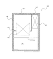
The sterilizer according to the present embodiment can be applied to various uses such as sterilizing liquids such as water (tap water) and gases such as air. In the former case, for example , it can be used to sterilize water by being attached to a pot-type water purifier, attached to a faucet, or installed in a water purifier attached to water. In the latter case, it can be used to sterilize the exhaust gas by attaching it to an exhaust pipe, for example. Here, as an example, a case of a cartridge type sterilizer to be mounted on a pot type water purifier will be described with reference to FIG.
図1に示すポット型の浄水器500は、ケース510と、ケース510の内部の空間を2つの領域に仕切る仕切り部520と、仕切り部520に装着される浄水カートリッジ550とを備えている。また、ケース510の上部には、水道水などの原水をケース510内に入れるための第1蓋530、及び浄化後の水を外部に排出させるための第2蓋540が設けられている。浄水カートリッジ550には、その内部に活性炭が充填されている。
A pot-
以上のように構成される浄水器500によれば、第1蓋530を開いた状態で、原水をケース510内に入れると、浄水カートリッジ550により浄化された水Wが、ケース510の下方に溜められる。そして、第2蓋540を開いた状態で、ケース510を第2蓋540側に傾けることによって、浄化された水Wを外部に排出させることができる。
According to the
ここで、上記のように構成される浄水器500の場合、ケース510内に溜められた水は、活性炭によって塩素が除去されている。そのため、長期間放置されると菌が発生して
しまう問題がある。そこで、本実施例に係る浄水器500においては、溜められた水Wを殺菌するために、第2蓋540の付近にカートリッジ型の殺菌装置100が装着されている。これにより、溜められていた浄化後の水Wをケース510の外部に排出する際には、当該水Wが殺菌装置100内の流路を通る際に紫外線によって殺菌される。
Here, in the case of the
(実施例1)
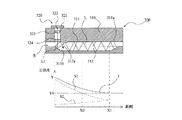
図2及び図3を参照して、本発明の実施例1に係る殺菌装置について説明する。図2は本発明の実施例1に係る殺菌装置の正面図である。図3は本発明の実施例1に係る殺菌装置の模式的断面図(図2中のAA断面図)である。なお、図3においては、断面図の下方に、流路Rの中心線上における一方側から他方側に向かう距離と光強度との関係をグラフで示している。
Example 1
With reference to FIG.2 and FIG.3, the sterilizer which concerns on Example 1 of this invention is demonstrated. FIG. 2 is a front view of the sterilizer according to
殺菌装置100は、殺菌対象となる流体(ここでは、水)の流路Rを有するハウジング110と、ハウジング110に設けられる光源ユニット120とを備えている。
The
光源ユニット120は、基板121と、基板121に取付けられるLED素子122と、LED素子122により照射された紫外線を集光するレンズ123とを備えている。LED素子122は、流路R内に紫外線を照射するための光源である。このLED素子122の個数は特に限定されるものではなく、基板121の長手方向(ハウジング110の幅方向)に複数個並べて配置させることができる。なお、LED素子122の電源(電池)に関しては、殺菌装置100(例えば、ハウジング110)に設けても良いし、殺菌装置100の外部(例えば、上述した浄水器500のケース510)に設けても良い。
The
また、光源ユニット120と流路Rとの間には、窓124が設けられている。この窓124は光源ユニット120が配置されている領域と流路Rとを仕切るために設けられている。すなわち、この窓124は、殺菌対象となる流体(水)が光源ユニット120側に向かわないように、紫外線は透過させつつ流体の光源ユニット120側への侵入を防止する役割を担っている。
Further, a
図2に示すように、ハウジング110に設けられる流路Rは、その断面が矩形となるように構成されている。図3に示すように、この流路Rの内壁面は、LED素子122から照射された紫外線を複数回反射させつつ、流路Rの一方側から他方側に向かわせる一対の反射面を有している。説明の便宜上、以下、これら一対の反射面を、適宜、それぞれ第1反射面111,第2反射面112と称する。なお、図3中の線Lは、LED素子122から照射された紫外線の中心(光軸)を示している。
As shown in FIG. 2, the flow path R provided in the
第1反射面111と第2反射面112は、いずれも表面が平面で構成されると共に、平面同士が平行になるように、かつ対向するように構成されている。そして、図3に示すように、これら第1反射面111と第2反射面112の法線に対して、LED素子122から照射された紫外線の向きが、流路Rの一方側から他方側に向かって傾くように、LED素子122(光源ユニット120)がハウジング110に対して配置されている。
The first reflecting
そして、本実施例においては、第1反射面111側には、第1反射面111よりも更に流路Rの他方側に、折り返し面111aが設けられている。この折り返し面111aは、流路Rの一方側から他方側に向かって複数回反射された後の光の光軸に対して垂直な面で構成されている。これにより、複数回反射された後の光は、折り返し面111aによって、元の方向に向かって折り返される。
In the present embodiment, a folded
図3中のグラフに示すように、光強度は距離の二乗に反比例するように減衰する。なお、図中、点線S1は流路Rの一方側から他方側に向かう紫外線の光強度であり、点線S2
は折り返し面111aにより折り返されることで、流路Rの他方側から一方側に向かう紫外線の光強度である。また、実線Tは流路R内を通る紫外線の光強度(つまりS1とS2を足し合わせたもの)である。
As shown in the graph in FIG. 3, the light intensity attenuates so as to be inversely proportional to the square of the distance. In the figure, the dotted line S1 is the light intensity of ultraviolet rays from one side of the flow path R to the other side, and the dotted line S2
Is the light intensity of the ultraviolet rays that are folded by the folded
背景技術の中でも説明したように、殺菌効果を得るためには、光強度が一定値以上である必要がある。本実施例においても、上記仮想技術と同様に、LED素子122により照射される紫外線によって殺菌効果を得るために必要な光強度をY0[J/cm2]とする。折り返し面111aを備えていない構成の場合には、光強度は点線S1に示す通りであり、距離X0[mm]までの領域でのみ殺菌効果が得られることになる。これに対して、本実施例においては、光強度がY0の1/2となる付近に、折り返し面111aを設けている。これにより、実線Tから分かるように、本実施例の場合には、折り返し面111aが設けられている距離X1(>X0)[mm]までの領域で殺菌効果を得ることができる。
As described in the background art, in order to obtain a bactericidal effect, the light intensity needs to be a certain value or more. Also in the present embodiment, similarly to the above-described virtual technique, the light intensity necessary for obtaining a bactericidal effect by ultraviolet rays irradiated by the
また、点線S2から分かる通り、流路Rの他方側から一方側に向かう紫外線の光強度は、光源ユニット120付近では十分低下している。また、流路Rの一方側に向かう紫外線は窓124を介して光源ユニット120側に侵入していく。従って、ハウジング110の外部に紫外線が漏れることは殆どない。
Further, as can be seen from the dotted line S2, the light intensity of the ultraviolet rays from the other side of the flow path R toward the one side is sufficiently reduced in the vicinity of the
<本実施例に係る殺菌装置の優れた点>
本実施例に係る殺菌装置100によれば、紫外線は、第1反射面111と第2反射面112によって、流路Rの一方側から他方側に向かって複数回反射された後に、折り返し面111aによって折り返されて、複数回反射しながら流路Rの他方側から一方側に向かっていく。
<Excellent point of sterilizer according to the present embodiment>
According to the
そのため、流路R内を通る紫外線の光強度は、流路Rの一方側から他方側に向かう紫外線の光強度(図3グラフ中の点線S1)と流路Rの他方側から一方側に向かう紫外線の光強度(同グラフ中の点線S2)を足し合わせたもの(同グラフ中の実線T)となる。従って、流路R内を通る紫外線の光強度を高めることができる。これにより、殺菌効果が得られる領域を拡げることが可能となる。また、流路Rの一方側から他方側に向かう紫外線を折り返し面111aで折り返すことができるので、紫外線がハウジング110の外に漏れてしまうことを抑制できる。これに伴い、紫外線の光強度を人体等に影響が出ないようにするためにハウジング110の全長を長くする必要がなく、ハウジング110を小型化することができる。また、紫外線がハウジング110の外に漏れてしまうことを抑制できるので、殺菌装置100を上記の浄水器500に用いた場合には、ケース510等の劣化を抑制することができる。
Therefore, the light intensity of the ultraviolet light passing through the flow path R is directed to the light intensity of the ultraviolet light (dotted line S1 in the graph of FIG. 3) from one side of the flow path R to the other side and from the other side of the flow path R to the one side. This is the sum of the UV light intensities (dotted line S2 in the graph) (solid line T in the graph). Therefore, the light intensity of ultraviolet rays passing through the flow path R can be increased. Thereby, it becomes possible to expand the area | region where the bactericidal effect is acquired. In addition, since the ultraviolet light traveling from one side to the other side of the flow path R can be folded back by the
なお、流路R内を流れる流体の方向は特に限定されるものではなく、例えば、図3中左側から右側に流しても良いし、右側から左側に流しても良い。 The direction of the fluid flowing in the flow path R is not particularly limited. For example, the fluid may flow from the left side to the right side in FIG. 3 or from the right side to the left side.
(実施例2)
図4及び図5には、本発明の実施例2が示されている。図4は本発明の実施例2に係る殺菌装置の正面図である。図5は本発明の実施例2に係る殺菌装置の模式的断面図(図4中のAA断面図)である。なお、図5においては、断面図の下方に、流路Rの中心線上における一方側から他方側に向かう距離と光強度との関係をグラフで示している。なお、本実施例に係る殺菌装置200の適用例については、図1を参照して説明した通りである。
(Example 2)
4 and 5 show a second embodiment of the present invention. FIG. 4 is a front view of a sterilizer according to
殺菌装置200は、殺菌対象となる流体の流路Rを有するハウジング210と、ハウジング210に設けられる光源ユニット220とを備えている。
The
光源ユニット220は、基板221と、基板221に取付けられるLED素子222と、LED素子222により照射された紫外線を集光するレンズ223とを備えている。LED素子222は、流路R内に紫外線を照射するための光源である。このLED素子222の個数は特に限定されるものではなく、基板221の長手方向(ハウジング210の幅方向)に複数個並べて配置させることができる。なお、LED素子222の電源(電池)に関しては、殺菌装置200(例えば、ハウジング210)に設けても良いし、殺菌装置200の外部(例えば、上述した浄水器500のケース510)に設けても良い。
The
また、光源ユニット220と流路Rとの間には、窓224が設けられている。この窓224は光源ユニット220が配置されている領域と流路Rとを仕切るために設けられている。すなわち、この窓224は、殺菌対象となる流体(水)が光源ユニット220側に向かわないように、紫外線は透過させつつ流体の光源ユニット220側への侵入を防止する役割を担っている。
A
図4に示すように、ハウジング210に設けられる流路Rは、その断面が矩形となるように構成されている。図5に示すように、この流路Rの内壁面は、LED素子222から照射された紫外線を複数回反射させつつ、流路Rの一方側から他方側に向かわせる一対の
反射面を有している。説明の便宜上、以下、これら一対の反射面を、適宜、それぞれ第1反射面211,第2反射面212と称する。なお、図5中の線Lは、LED素子222から照射された紫外線の中心(光軸)を示している。
As shown in FIG. 4, the flow path R provided in the
第1反射面211と第2反射面212は、いずれも表面が平面で構成されると共に、平面同士が平行になるように、かつ対向するように構成されている。そして、図5に示すように、LED素子222から照射された紫外線の向きが、これら第1反射面211と第2反射面212の法線と一致するように、LED素子222(光源ユニット220)がハウジング210に対して配置されている。
Each of the first reflecting
そして、本実施例においても、実施例1の場合と同様に、第1反射面211側には、第1反射面211よりも更に流路Rの他方側に、折り返し面211aが設けられている。この折り返し面211aは、流路Rの一方側から他方側に向かって複数回反射された後の光の光軸に対して垂直な面で構成されている。これにより、複数回反射された後の光は、折り返し面211aによって、元の方向に向かって折り返される。
Also in the present embodiment, as in the case of the first embodiment, a
そして、本実施例の場合には、第1反射面211よりも更に流路Rの一方側に、LED素子222から照射された紫外線を流路Rの他方側に向かって傾くように反射させる予備反射面211bが設けられている。この予備反射面211bを設けたことにより、LED素子222から照射された紫外線が予備反射面211bによって反射された後は、紫外線の光路は、上記実施例1と同様となる。従って、図5中のグラフに示すように、距離と光強度の関係は、実施例1の場合(図3中のグラフ)と同様となる。
In the case of the present embodiment, the spare that reflects the ultraviolet rays irradiated from the
以上より、本実施例に係る殺菌装置200においても、上記実施例1に係る殺菌装置100と同様の効果を得ることができる。また、上記実施例1に係る殺菌装置100の場合には光源ユニット120をハウジング110に対して斜めに配置させる構成であるのに対して、本実施例に係る殺菌装置200の場合には、光源ユニット220をハウジング210に対して斜めに配置させる必要がないため、装置全体をより小型化させることができる利点を有している。
As described above, also in the
ここで、図6を参照して、本実施例に係る殺菌装置が不利となり得るケースについて説明する。 Here, with reference to FIG. 6, the case where the sterilizer which concerns on a present Example may become disadvantageous is demonstrated.
上記の通り、光源ユニット220と流路Rとの間には、窓224が設けられている。ここで、LED素子222から照射された紫外線が最初に反射された反射光は、窓224に入り込まないようにするのが望ましい。何故なら、反射光のうち窓224に入り込んでしまう光は、その後流路R内には戻らず、殺菌に寄与しないため、殺菌効率が低下してしまうからである。
As described above, the
図6(a)はLED素子222から照射された紫外線について、その中心(光軸)は窓224には入り込まずに第2反射面212によって反射されるものの、紫外線の一部は窓224に入り込んでしまっている場合を示している(線L1参照)。この例では、LED素子222から照射された紫外線のほぼ半分が窓224に入り込んでしまっている。
FIG. 6A shows the ultraviolet light emitted from the
この対策として、LED素子222側から流路R内に向かう紫外線については透過させ、流路R内からLED素子222側に向かう紫外線については反射させるハーフミラーを、窓224に設けることができる。例えば、ガラスからなる窓224の表面に薄い金属膜を蒸着させるハーフミラー処理を施すことができる。ただし、ハーフミラーの透過率や反射率は通常のミラーに比べると低く光量が低下してしまう。そのため、各種部材の配置構成によって、反射光が窓224に入り込まないようにするのが望ましい。
As a countermeasure, the
例えば、窓224から予備反射面211bまでの距離を長くすることで、反射光が窓224に入り込まないようにすることができる。しかしながら、この場合には、第1反射面211と第2反射面212との距離が長くなり、ハウジング210が大きくなり、殺菌装置200の小型化に支障を来してしまう欠点がある。
For example, it is possible to prevent the reflected light from entering the
また、予備反射面211bの傾きを急こう配にすることによって、反射光が窓224に入り込まないようにすることもできる。しかしながら、この場合には、紫外線が反射してから次に反射するまでの距離が長くなってしまう。そのため、流路R内において、紫外線が通過しない領域ができて(増えて)しまう。この点について、図6(b)を参照して、より詳しく説明する。
Further, it is possible to prevent the reflected light from entering the
図6(b)に示すように、予備反射面211bの傾きを急こう配にすることで、窓224から予備反射面211bまでの距離を長くしなくても、反射光が窓224に入り込まないようにすることができる。なお、図中、線L1は流路Rの最も一方の側を通る光路を示している。
As shown in FIG. 6B, by making the inclination of the
しかしながら、この場合には、紫外線が第1反射面211で反射されてから第2反射面212に到達するまでの距離(流路Rの一方側から他方側方向の距離)及び第2反射面212で反射されてから第1反射面211に到達するまでの距離が長くなる。そのため、流路R内において、紫外線が通過しない領域Zができてしまう。従って、殺菌効率が低下する原因となる。そこで、次に、このような不具合を解消させることが可能な実施例について説明する。
However, in this case, the distance from the time when the ultraviolet rays are reflected by the first reflecting
(実施例3)
図7及び図8には、本発明の実施例3が示されている。図7は本発明の実施例3に係る殺菌装置の正面図である。図8は本発明の実施例3に係る殺菌装置の模式的断面図(図7中のAA断面図)である。なお、図8においては、断面図の下方に、流路Rの中心線上における一方側から他方側に向かう距離と光強度との関係をグラフで示している。なお、本実施例に係る殺菌装置300の適用例については、図1を参照して説明した通りである。
(Example 3)
7 and 8 show a third embodiment of the present invention. FIG. 7 is a front view of a sterilizer according to Embodiment 3 of the present invention. FIG. 8 is a schematic cross-sectional view (AA cross-sectional view in FIG. 7) of the sterilizer according to Embodiment 3 of the present invention. In FIG. 8, the relationship between the light intensity and the distance from the one side to the other side on the center line of the flow path R is shown in a graph below the cross-sectional view. An application example of the
殺菌装置300は、殺菌対象となる流体の流路Rを有するハウジング310と、ハウジング310に設けられる光源ユニット320とを備えている。
The
光源ユニット320は、基板321と、基板321に取付けられるLED素子322と、LED素子322により照射された紫外線を集光するレンズ323とを備えている。LED素子322は、流路R内に紫外線を照射するための光源である。このLED素子322の個数は特に限定されるものではなく、基板321の長手方向(ハウジング310の幅方向)に複数個並べて配置させることができる。なお、LED素子322の電源(電池)に関しては、殺菌装置300(例えば、ハウジング310)に設けても良いし、殺菌装置300の外部(例えば、上述した浄水器500のケース510)に設けても良い。
The
また、光源ユニット320と流路Rとの間には、窓324が設けられている。この窓324は光源ユニット320が配置されている領域と流路Rとを仕切るために設けられている。すなわち、この窓324は、殺菌対象となる流体(水)が光源ユニット320側に向かわないように、紫外線は透過させつつ流体の光源ユニット320側への侵入を防止する役割を担っている。
Further, a
図7に示すように、ハウジング310に設けられる流路Rは、その断面が矩形となるように構成されている。図8に示すように、この流路Rの内壁面は、LED素子322から照射された紫外線を複数回反射させつつ、流路Rの一方側から他方側に向かわせる一対の反射面を有している。説明の便宜上、以下、これら一対の反射面を、適宜、それぞれ第1反射面311,第2反射面312と称する。なお、図8中の線Lは、LED素子322から照射された紫外線の中心(光軸)を示している。
As shown in FIG. 7, the flow path R provided in the
第1反射面311と第2反射面312は、いずれも表面が平面で構成されると共に、平面同士が平行になるように、かつ対向するように構成されている。そして、図8に示すように、LED素子322から照射された紫外線の向きが、これら第1反射面311と第2反射面312の法線と一致するように、LED素子322(光源ユニット320)がハウジング310に対して配置されている。
The first reflecting
そして、本実施例においても、実施例1の場合と同様に、第1反射面311側には、第1反射面311よりも更に流路Rの他方側に、折り返し面311aが設けられている。この折り返し面311aは、流路Rの一方側から他方側に向かって複数回反射された後の光の光軸に対して垂直な面で構成されている。これにより、複数回反射された後の光は、折り返し面311aによって、元の方向に向かって折り返される。
Also in the present embodiment, as in the case of the first embodiment, a folded surface 311a is provided on the first
また、本実施例の場合には、実施例2の場合と同様に、第1反射面311よりも更に流路Rの一方側に、LED素子322から照射された紫外線を流路Rの他方側に向かって傾くように反射させる予備反射面311bが設けられている。この予備反射面311bは、LED素子322から照射された紫外線の反射光が窓324に入り込まないように、急こう配な角度となるように設けられている。なお、図中、線L1は流路Rの最も一方の側を通る光路を示している。
Further, in the case of the present embodiment, as in the case of the second embodiment, the ultraviolet ray irradiated from the
そして、本実施例の場合には、第2反射面312よりも更に流路Rの一方側に、紫外線の反射光の向きを調整する反射方向調整面312aが設けられている。この反射方向調整面312aを設けたことにより、LED素子322から照射された紫外線が予備反射面311bによって反射され、更に、反射方向調整面312aによって反射された後は、紫外線の光路は、上記実施例1と同様となる。従って、図8中のグラフに示すように、距離と光強度の関係は、実施例1の場合(図3中のグラフ)と同様となる。
In the case of the present embodiment, a reflection
以上より、本実施例に係る殺菌装置300においても、上記実施例1に係る殺菌装置100と同様の効果を得ることができる。また、上記実施例1に係る殺菌装置100の場合
には光源ユニット120をハウジング110に対して斜めに配置させる構成であるのに対して、本実施例に係る殺菌装置300の場合には、実施例2の場合と同様に、光源ユニット320をハウジング310に対して斜めに配置させる必要がないため、装置全体をより小型化させることができる利点を有している。
As described above, also in the
なお、本実施例においては、上記実施例2で示した構成に、更に、反射方向調整面を加える構成を採用した場合を示した。そして、当該構成を採用したことによって、LED素子から照射された紫外線のうち最初に反射された反射光が窓に侵入しないようにし、かつ、光路内において紫外線が通らない領域をなくす(少なくする)ことを可能にした。しかしながら、上記実施例1で示した構成においても、光源ユニット(LED素子)の向きによっては、光路内において紫外線が通らない領域が存在してしまう(増えてしまう)こともあり得る。従って、そのような場合には、実施例1で示した構成に対して、本実施例で示したような反射方向調整面を設けることで、光路を調整し、光路内において紫外線が通らない領域をなくす(少なくする)ようにすることもできる。 In the present embodiment, the case where a configuration in which a reflection direction adjustment surface is further added to the configuration shown in the second embodiment is shown. And by adopting the said structure, the reflected light reflected first among the ultraviolet rays irradiated from the LED element is prevented from entering the window, and the region where the ultraviolet rays do not pass in the optical path is eliminated (reduced). Made it possible. However, even in the configuration shown in the first embodiment, depending on the direction of the light source unit (LED element), there may be a region where the ultraviolet rays do not pass in the optical path (increased). Accordingly, in such a case, the optical path is adjusted by providing the reflection direction adjusting surface as shown in the present embodiment with respect to the configuration shown in the first embodiment, and the ultraviolet ray does not pass through the optical path. Can be eliminated (reduced).
なお、上記各実施例で示したLED素子については、例えば、オンオフスイッチを設けることによって、使用する際にのみ紫外線を照射させるようにすればよい。 In addition, about the LED element shown in the said each Example, it is sufficient to irradiate an ultraviolet-ray only when using it by providing an on-off switch, for example.
100,200,300 殺菌装置
110,210,310 ハウジング
111,211,311 第1反射面
111a,211a,311a 折り返し面
112,212,312 第2反射面
120,220,320 光源ユニット
121,221,321 基板
122,222,322 LED素子
123,223,323 レンズ
124,224,324 窓
211b,311b 予備反射面
312a 反射方向調整面
500 浄水器
510 ケース
520 仕切り部
530 第1蓋
540 第2蓋
550 浄水カートリッジ
100, 200, 300
Claims (1)
該ハウジングに設けられ、前記流路内に紫外線を照射する光源と、
を備える殺菌装置において、
前記流路の内壁面は、前記光源から照射された紫外線を複数回反射させつつ、前記流路の一方側から他方側に向かわせる一対の反射面を有すると共に、
前記一対の反射面のうちの一方の反射面側には、前記一方側から他方側に向かって複数回反射された後の光の光軸に対して垂直な面で構成され、当該光を元の方向に向かって折り返す折り返し面が設けられていることを特徴とする殺菌装置。 A housing having a fluid flow path to be sterilized;
A light source provided in the housing for irradiating ultraviolet rays into the flow path;
In a sterilizer comprising:
The inner wall surface of the flow path has a pair of reflection surfaces that are directed from the one side of the flow path to the other side while reflecting the ultraviolet ray irradiated from the light source a plurality of times,
One reflection surface side of the pair of reflection surfaces is configured by a surface perpendicular to the optical axis of the light after being reflected a plurality of times from the one side toward the other side. A sterilizing apparatus is provided, wherein a folding surface is provided that is folded back toward the direction.
Priority Applications (6)
| Application Number | Priority Date | Filing Date | Title |
|---|---|---|---|
| JP2012115880A JP5874532B2 (en) | 2012-05-21 | 2012-05-21 | Sterilizer |
| CN201380026759.0A CN104334198B (en) | 2012-05-21 | 2013-04-25 | Sterilizing unit |
| US14/402,130 US9233857B2 (en) | 2012-05-21 | 2013-04-25 | Sterilization device |
| KR1020147032103A KR101617989B1 (en) | 2012-05-21 | 2013-04-25 | Sterilization device |
| PCT/JP2013/062247 WO2013175931A1 (en) | 2012-05-21 | 2013-04-25 | Sterilization device |
| GB1420925.8A GB2519243B (en) | 2012-05-21 | 2013-04-25 | A sterilization device |
Applications Claiming Priority (1)
| Application Number | Priority Date | Filing Date | Title |
|---|---|---|---|
| JP2012115880A JP5874532B2 (en) | 2012-05-21 | 2012-05-21 | Sterilizer |
Publications (3)
| Publication Number | Publication Date |
|---|---|
| JP2013240487A JP2013240487A (en) | 2013-12-05 |
| JP2013240487A5 JP2013240487A5 (en) | 2015-06-11 |
| JP5874532B2 true JP5874532B2 (en) | 2016-03-02 |
Family
ID=49623630
Family Applications (1)
| Application Number | Title | Priority Date | Filing Date |
|---|---|---|---|
| JP2012115880A Expired - Fee Related JP5874532B2 (en) | 2012-05-21 | 2012-05-21 | Sterilizer |
Country Status (6)
| Country | Link |
|---|---|
| US (1) | US9233857B2 (en) |
| JP (1) | JP5874532B2 (en) |
| KR (1) | KR101617989B1 (en) |
| CN (1) | CN104334198B (en) |
| GB (1) | GB2519243B (en) |
| WO (1) | WO2013175931A1 (en) |
Families Citing this family (18)
| Publication number | Priority date | Publication date | Assignee | Title |
|---|---|---|---|---|
| JP6236629B2 (en) * | 2014-01-07 | 2017-11-29 | パナソニックIpマネジメント株式会社 | UV sterilizer for fluid |
| JP2017510997A (en) * | 2014-04-07 | 2017-04-13 | クリスタル アイエス, インコーポレーテッドCrystal Is, Inc. | Ultraviolet light emitting device and method |
| JP6355244B2 (en) * | 2014-06-30 | 2018-07-11 | 国立大学法人埼玉大学 | UV irradiation equipment |
| BR112017001802A2 (en) | 2014-07-28 | 2017-11-21 | Typhon Treat Systems Limited | fluid treatment method, system and apparatus |
| US10246348B2 (en) | 2015-06-08 | 2019-04-02 | Rayvio Corporation | Ultraviolet disinfection system |
| US9540252B1 (en) | 2015-06-08 | 2017-01-10 | Rayvio Corporation | Ultraviolet disinfection system |
| JP6188969B1 (en) | 2016-01-07 | 2017-08-30 | 三菱電機株式会社 | Ultraviolet sterilizer and air conditioner using the same |
| JP6682346B2 (en) * | 2016-05-16 | 2020-04-15 | 国立大学法人埼玉大学 | UV irradiation device |
| JP6807174B2 (en) * | 2016-06-15 | 2021-01-06 | 国立大学法人埼玉大学 | Ultraviolet irradiation device |
| KR102493051B1 (en) * | 2016-09-20 | 2023-01-31 | 가부시키가이샤 닛스이 | Method for manufacturing fish roe paste with foreign substances removed and apparatus for manufacturing fish roe paste with foreign substances removed |
| JP6530150B2 (en) * | 2017-02-09 | 2019-06-12 | 株式会社アクアバンク | Beverage sterilization unit and drinking water supply device equipped with the same |
| JP7084574B2 (en) * | 2017-09-22 | 2022-06-15 | 株式会社アクアバンク | UV sterilizer and drinking water supply equipment equipped with it |
| JP6963956B2 (en) * | 2017-09-28 | 2021-11-10 | 株式会社エンプラス | UV sterilizer and UV irradiation device |
| JPWO2019151364A1 (en) * | 2018-02-02 | 2021-01-28 | 株式会社エンプラス | UV sterilization tube and UV sterilizer |
| US11365134B2 (en) | 2019-07-31 | 2022-06-21 | Access Business Group International Llc | Water treatment system |
| KR102343587B1 (en) * | 2020-06-05 | 2021-12-27 | 주식회사 웰빙 | Disinfectant Spray |
| DE102020119962A1 (en) | 2020-07-29 | 2022-02-03 | LED3.0 GmbH | Device and method for sterilizing air |
| CN111939304A (en) * | 2020-10-19 | 2020-11-17 | 武汉光谷航天三江激光产业技术研究院有限公司 | Laser virus killing device based on beam shaping and refraction and reflection control |
Family Cites Families (14)
| Publication number | Priority date | Publication date | Assignee | Title |
|---|---|---|---|---|
| JPS63144835A (en) * | 1986-12-06 | 1988-06-17 | Soehara Kogyo Kk | Manufacture of tableware with twisted handle |
| JPH055943Y2 (en) * | 1987-03-13 | 1993-02-16 | ||
| US6773608B1 (en) * | 1998-05-13 | 2004-08-10 | Uv Pure Technologies Inc. | Ultraviolet treatment for aqueous liquids |
| JP2000334448A (en) | 1999-05-31 | 2000-12-05 | Kuniyasu Iwasaki | Device for sterilizing and purifying fluid |
| US6447721B1 (en) | 2000-07-31 | 2002-09-10 | Remotelight, Inc. | Drinking water UV disinfection system and method |
| IL157229A (en) | 2003-08-04 | 2006-08-20 | Zamir Tribelsky | Method for energy coupling especially useful for disinfecting and various systems using it |
| JP2007139230A (en) * | 2005-11-15 | 2007-06-07 | Keiji Iimura | Refrigerator having photocatalyst |
| JP2010214241A (en) | 2009-03-13 | 2010-09-30 | Panasonic Electric Works Co Ltd | Water purifier |
| JP5374697B2 (en) * | 2009-07-09 | 2013-12-25 | ユーヴィックス株式会社 | UV sterilization water purifier and UV LED unit used for it |
| US20110291995A1 (en) * | 2010-05-25 | 2011-12-01 | Industrial Technology Research Institute | Sterilizing device and manufacturing method for sterilizing device |
| US20120168641A1 (en) * | 2010-09-08 | 2012-07-05 | Lizotte Todd E | Uv ptfe diffuser technology |
| DE102010047318A1 (en) * | 2010-10-01 | 2012-04-05 | Schott Ag | Ultraviolet semiconductor light source irradiation device useful for e.g. sterilization and physical excitation of molecules into higher physical excitation state, comprises ultraviolet semiconductor light source and irradiation chamber |
| WO2012141709A1 (en) * | 2011-04-14 | 2012-10-18 | Empire Technology Development Llc | Ultraviolet water sterilization |
| JP2013158706A (en) * | 2012-02-06 | 2013-08-19 | Panasonic Corp | Water purification apparatus |
-
2012
- 2012-05-21 JP JP2012115880A patent/JP5874532B2/en not_active Expired - Fee Related
-
2013
- 2013-04-25 GB GB1420925.8A patent/GB2519243B/en not_active Expired - Fee Related
- 2013-04-25 CN CN201380026759.0A patent/CN104334198B/en not_active Expired - Fee Related
- 2013-04-25 US US14/402,130 patent/US9233857B2/en not_active Expired - Fee Related
- 2013-04-25 WO PCT/JP2013/062247 patent/WO2013175931A1/en active Application Filing
- 2013-04-25 KR KR1020147032103A patent/KR101617989B1/en active IP Right Grant
Also Published As
| Publication number | Publication date |
|---|---|
| GB201420925D0 (en) | 2015-03-18 |
| GB2519243A (en) | 2015-04-15 |
| CN104334198B (en) | 2016-10-12 |
| JP2013240487A (en) | 2013-12-05 |
| CN104334198A (en) | 2015-02-04 |
| US20150129777A1 (en) | 2015-05-14 |
| WO2013175931A1 (en) | 2013-11-28 |
| KR20150008413A (en) | 2015-01-22 |
| KR101617989B1 (en) | 2016-05-03 |
| GB2519243B (en) | 2017-08-02 |
| US9233857B2 (en) | 2016-01-12 |
Similar Documents
| Publication | Publication Date | Title |
|---|---|---|
| JP5874532B2 (en) | Sterilizer | |
| KR20210116392A (en) | a flowable typed sterilizing device and connector using the same | |
| JP7262985B2 (en) | Light source module device, Fluid sterilization device | |
| WO2014077293A1 (en) | Air purifier | |
| KR100891031B1 (en) | Ultraviolet disinfecting apparatus | |
| WO2014058011A1 (en) | Disinfection device | |
| WO2015020041A1 (en) | Ultraviolet sterilization device | |
| JP7084574B2 (en) | UV sterilizer and drinking water supply equipment equipped with it | |
| JP2016507367A (en) | Liquid purification apparatus and method | |
| JP6963956B2 (en) | UV sterilizer and UV irradiation device | |
| KR102070611B1 (en) | Water sterilization system | |
| KR102505921B1 (en) | a flowable typed sterilizing device and connector using the same | |
| JP2014076422A (en) | Sterilizer | |
| CN111320230A (en) | Device for disinfecting a fluid | |
| JP2018064771A (en) | Ultraviolet irradiation device | |
| KR20180115978A (en) | Sterilizing apparatus for fluid | |
| JP2014076205A (en) | Sterilizer | |
| KR20170051859A (en) | Apparatus for sterilizing water and water purifier therewith | |
| CN114712545A (en) | Air sterilizing device | |
| US10639393B1 (en) | Fluid system with integrated disinfecting optics | |
| JP7071144B2 (en) | UV sterilizer and UV irradiation device | |
| JP2020014647A (en) | Ultraviolet sterilization device, and ultraviolet irradiation device | |
| KR20090087204A (en) | Ultra violet filter for water purifier | |
| WO2021070350A1 (en) | Ultraviolet sterilization device and ultraviolet irradiation device | |
| WO2022148746A1 (en) | A light emitting device |
Legal Events
| Date | Code | Title | Description |
|---|---|---|---|
| A621 | Written request for application examination |
Free format text: JAPANESE INTERMEDIATE CODE: A621 Effective date: 20150416 |
|
| A521 | Request for written amendment filed |
Free format text: JAPANESE INTERMEDIATE CODE: A523 Effective date: 20150421 |
|
| TRDD | Decision of grant or rejection written | ||
| A01 | Written decision to grant a patent or to grant a registration (utility model) |
Free format text: JAPANESE INTERMEDIATE CODE: A01 Effective date: 20151222 |
|
| A61 | First payment of annual fees (during grant procedure) |
Free format text: JAPANESE INTERMEDIATE CODE: A61 Effective date: 20160104 |
|
| R150 | Certificate of patent or registration of utility model |
Ref document number: 5874532 Country of ref document: JP Free format text: JAPANESE INTERMEDIATE CODE: R150 |
|
| LAPS | Cancellation because of no payment of annual fees |