JP5872260B2 - Gas insulation device for electric power and its manufacturing method - Google Patents
Gas insulation device for electric power and its manufacturing method Download PDFInfo
- Publication number
- JP5872260B2 JP5872260B2 JP2011255049A JP2011255049A JP5872260B2 JP 5872260 B2 JP5872260 B2 JP 5872260B2 JP 2011255049 A JP2011255049 A JP 2011255049A JP 2011255049 A JP2011255049 A JP 2011255049A JP 5872260 B2 JP5872260 B2 JP 5872260B2
- Authority
- JP
- Japan
- Prior art keywords
- gas
- pressure
- arc
- insulating
- flow path
- Prior art date
- Legal status (The legal status is an assumption and is not a legal conclusion. Google has not performed a legal analysis and makes no representation as to the accuracy of the status listed.)
- Active
Links
Images


Classifications
-
- H—ELECTRICITY
- H01—ELECTRIC ELEMENTS
- H01H—ELECTRIC SWITCHES; RELAYS; SELECTORS; EMERGENCY PROTECTIVE DEVICES
- H01H33/00—High-tension or heavy-current switches with arc-extinguishing or arc-preventing means
- H01H33/70—Switches with separate means for directing, obtaining, or increasing flow of arc-extinguishing fluid
- H01H33/88—Switches with separate means for directing, obtaining, or increasing flow of arc-extinguishing fluid the flow of arc-extinguishing fluid being produced or increased by movement of pistons or other pressure-producing parts
- H01H33/90—Switches with separate means for directing, obtaining, or increasing flow of arc-extinguishing fluid the flow of arc-extinguishing fluid being produced or increased by movement of pistons or other pressure-producing parts this movement being effected by or in conjunction with the contact-operating mechanism
- H01H33/91—Switches with separate means for directing, obtaining, or increasing flow of arc-extinguishing fluid the flow of arc-extinguishing fluid being produced or increased by movement of pistons or other pressure-producing parts this movement being effected by or in conjunction with the contact-operating mechanism the arc-extinguishing fluid being air or gas
-
- H—ELECTRICITY
- H05—ELECTRIC TECHNIQUES NOT OTHERWISE PROVIDED FOR
- H05K—PRINTED CIRCUITS; CASINGS OR CONSTRUCTIONAL DETAILS OF ELECTRIC APPARATUS; MANUFACTURE OF ASSEMBLAGES OF ELECTRICAL COMPONENTS
- H05K5/00—Casings, cabinets or drawers for electric apparatus
- H05K5/06—Hermetically-sealed casings
-
- H—ELECTRICITY
- H01—ELECTRIC ELEMENTS
- H01H—ELECTRIC SWITCHES; RELAYS; SELECTORS; EMERGENCY PROTECTIVE DEVICES
- H01H33/00—High-tension or heavy-current switches with arc-extinguishing or arc-preventing means
- H01H33/02—Details
- H01H33/53—Cases; Reservoirs, tanks, piping or valves, for arc-extinguishing fluid; Accessories therefor, e.g. safety arrangements, pressure relief devices
- H01H33/56—Gas reservoirs
-
- H—ELECTRICITY
- H02—GENERATION; CONVERSION OR DISTRIBUTION OF ELECTRIC POWER
- H02B—BOARDS, SUBSTATIONS OR SWITCHING ARRANGEMENTS FOR THE SUPPLY OR DISTRIBUTION OF ELECTRIC POWER
- H02B13/00—Arrangement of switchgear in which switches are enclosed in, or structurally associated with, a casing, e.g. cubicle
- H02B13/02—Arrangement of switchgear in which switches are enclosed in, or structurally associated with, a casing, e.g. cubicle with metal casing
- H02B13/025—Safety arrangements, e.g. in case of excessive pressure or fire due to electrical defect
-
- H—ELECTRICITY
- H01—ELECTRIC ELEMENTS
- H01H—ELECTRIC SWITCHES; RELAYS; SELECTORS; EMERGENCY PROTECTIVE DEVICES
- H01H33/00—High-tension or heavy-current switches with arc-extinguishing or arc-preventing means
- H01H33/02—Details
- H01H33/53—Cases; Reservoirs, tanks, piping or valves, for arc-extinguishing fluid; Accessories therefor, e.g. safety arrangements, pressure relief devices
- H01H33/56—Gas reservoirs
- H01H2033/566—Avoiding the use of SF6
-
- H—ELECTRICITY
- H01—ELECTRIC ELEMENTS
- H01H—ELECTRIC SWITCHES; RELAYS; SELECTORS; EMERGENCY PROTECTIVE DEVICES
- H01H33/00—High-tension or heavy-current switches with arc-extinguishing or arc-preventing means
- H01H33/02—Details
- H01H33/53—Cases; Reservoirs, tanks, piping or valves, for arc-extinguishing fluid; Accessories therefor, e.g. safety arrangements, pressure relief devices
- H01H33/56—Gas reservoirs
- H01H2033/568—Gas reservoirs with overpressure release, e.g. rupture membranes
-
- H—ELECTRICITY
- H02—GENERATION; CONVERSION OR DISTRIBUTION OF ELECTRIC POWER
- H02B—BOARDS, SUBSTATIONS OR SWITCHING ARRANGEMENTS FOR THE SUPPLY OR DISTRIBUTION OF ELECTRIC POWER
- H02B5/00—Non-enclosed substations; Substations with enclosed and non-enclosed equipment
Description
本発明の実施形態は、電力用ガス絶縁機器およびその製造方法に関する。 Embodiments described herein relate generally to a power gas insulation apparatus and a method for manufacturing the same .
電力の送配電・変電システムにおいては、高電圧の絶縁媒体として六弗化硫黄ガス(以下、SF6ガス)を利用した、ガス絶縁開閉装置、ガス遮断器、ガス断路器、ガス絶縁変圧器、ガス絶縁送電管など(以下、電力用ガス絶縁機器)の様々な機器が使用されている。これらの機器においては、SF6ガスを高電圧絶縁媒体のみならず、通電時の発熱を対流により冷却する冷却媒体として、また、ガス遮断器、ガス断路器など電流開閉を伴う機器においては、開閉動作時に発生するアーク放電を消滅させる消弧媒体としても用いている。 In power transmission / distribution / transformation systems, gas-insulated switchgear, gas circuit breakers, gas disconnectors, gas-insulated transformers using sulfur hexafluoride gas (hereinafter referred to as SF 6 gas) as a high-voltage insulating medium, Various devices such as gas-insulated power transmission pipes (hereinafter referred to as power gas-insulating devices) are used. In these devices, SF 6 gas is used not only as a high-voltage insulating medium, but also as a cooling medium that cools the heat generated by energization by convection, and in devices with current switching such as gas circuit breakers and gas disconnectors It is also used as an arc extinguishing medium that extinguishes arc discharge generated during operation.
SF6ガスは非常に安定した不活性なガスであり、無毒、不燃性であると同時に、電気絶縁性能、および放電を消滅させる性能(以下、消弧性能)に極めて優れたガスであり、送配電・変電機器に用いられる電力用ガス絶縁機器の高性能化、コンパクト化に大きく寄与している。 SF 6 gas is a very stable and inert gas. It is non-toxic and non-flammable, and at the same time has excellent electrical insulation performance and performance to extinguish discharge (hereinafter referred to as arc extinguishing performance). It greatly contributes to the improvement in performance and compactness of power gas insulation equipment used in power distribution and transformation equipment.
SF6ガスは電力用ガス絶縁機器において非常に適したガスといえるが、高い地球温暖化作用を有することが知られており、近年、その使用量の削減が望まれている。地球温暖化作用の大きさは一般に地球温暖化係数、すなわちCO2ガスを1とした場合の相対値により表され、SF6ガスの地球温暖化係数は23,900に及ぶことが知られている。このため、電力用ガス絶縁機器における絶縁ガスとして、地球温暖化係数が非常に大きな人工ガスであるSF6の代わりに他のガスを適用することが提案されている。 Although SF 6 gas can be said to be a very suitable gas in power gas insulation equipment, it is known to have a high global warming action, and in recent years, reduction of its use amount is desired. The magnitude of global warming action is generally expressed by a global warming coefficient, that is, a relative value when CO 2 gas is 1, and it is known that the global warming coefficient of SF 6 gas reaches 23,900. . For this reason, it has been proposed to apply another gas instead of SF 6 which is an artificial gas having a very large global warming potential as an insulating gas in a gas insulating device for electric power.
具体的には、N2ガスやCO2ガス、およびそれらを主成分とした混合ガスを適用することが検討されている。N2ガスやCO2ガスは、天然に存在するガスであり環境に優しく、地球温暖化作用がSF6ガスに比べて23,900分の1以下と極めて小さいため、N2ガスやCO2ガスをSF6ガスの代わりに電力用ガス絶縁機器に適用することで、地球温暖化への影響を大幅に抑制することが可能である。N2ガスとCO2ガスの絶縁性能および消弧性能はSF6ガスに比べると劣るものの、充填ガス圧力を高めたり、機器等の構造に種々の工夫を行うことにより、性能を高めることが検討されている。すなわち、SF6ガスの代わりにN2ガス、CO2ガスなどを適用することで、概ね良好な性能を有し、かつ地球温暖化への影響を抑制した環境に優しい電力用ガス絶縁機器を提供することが可能である。 Specifically, it has been studied to apply N 2 gas, CO 2 gas, and a mixed gas containing these as main components. N 2 gas and CO 2 gas, gentle to a gas naturally occurring environment, global warming effect is very small and less than 1 23,900 minutes as compared with SF 6 gas, N 2 gas and CO 2 gas Is applied to power gas insulation equipment instead of SF 6 gas, it is possible to greatly suppress the impact on global warming. Although the insulation performance and arc extinguishing performance of N 2 gas and CO 2 gas are inferior to those of SF 6 gas, it is considered to increase the performance by increasing the filling gas pressure or by making various modifications to the structure of the equipment. Has been. In other words, by providing N 2 gas, CO 2 gas, etc. instead of SF 6 gas, we provide environment-friendly power gas insulation equipment that has generally good performance and suppresses the impact on global warming. Is possible.
電力用ガス絶縁機器の運用時においては、何らかの不具合等により密閉タンク内でのアーク(以下、内部アーク)が発生する可能性がある。内部アークが発生すると、過大な短絡電流が流れるため、その高熱により密閉タンク内の当該ガス区分の圧力は急激に上昇する。 During operation of power gas insulation equipment, an arc in the sealed tank (hereinafter referred to as an internal arc) may occur due to some trouble or the like. When an internal arc occurs, an excessive short-circuit current flows, so that the pressure of the gas section in the sealed tank rapidly increases due to the high heat.
この圧力で密閉タンクが破裂すると周囲に重大な危険を及ぼす。このため、密閉タンク内の圧力が異常上昇した場合に放圧動作を行う放圧装置を設けることがある。しかしながら、現在多くに使用されているSF6ガスは前述の通り大気放出されると環境に悪影響を及ぼすと同時に、アークの高温で解離すると有毒な分解生成物を発生することが知られている。このため、たとえ密閉タンク内で内部アークが発生しようとも、当該内部アークが発生しているガス区分で圧力を保持し、密閉タンクの外部へのガス放出を避けるよう、密閉タンクおよび絶縁スペーサにそれ相当の機械的強度を持たせるように設計されることが多く、また環境面でも望まれている。 If the sealed tank ruptures at this pressure, there is a serious danger to the surroundings. For this reason, a pressure relief device that performs a pressure relief operation when the pressure in the sealed tank abnormally rises may be provided. However, it is known that SF 6 gas, which is currently widely used, adversely affects the environment when released into the atmosphere as described above, and at the same time generates toxic decomposition products when dissociated at high temperatures of the arc. For this reason, even if an internal arc is generated in the closed tank, the pressure is maintained in the gas section where the internal arc is generated, and the closed tank and the insulating spacer are adjusted so as to avoid gas discharge to the outside of the closed tank. It is often designed to have considerable mechanical strength and is also desirable from an environmental standpoint.
しかしながら、電力用ガス絶縁機器において、環境に考慮してSF6ガスの代わりにN2ガスやCO2ガス等を絶縁ガスとして用いた場合、これらのガスはSF6ガスよりも単位体積当たりの熱容量が小さいため、内部アークが発生した際に、SF6ガスに比べて内部アークに起因する同じ発熱量に対する温度上昇が大きくなる。そのため、密閉タンク内の内部アークが発生したガス区分における内部圧力が大幅に高く上昇することが分かってきた。例えば、密閉タンク内において、同一の容積およびガス圧力のガス区分で同一の電流および時間の内部アークが発生した場合に、SF6ガスとCO2ガスおよびN2ガスの圧力上昇を比較すると、SF6ガスに比べてCO2ガスでは3.3倍、N2ガスでは4.7倍もの圧力上昇となることがわかった。 However, in the gas insulation equipment for electric power, when N 2 gas, CO 2 gas or the like is used as the insulating gas instead of SF 6 gas in consideration of the environment, these gases have a heat capacity per unit volume more than SF 6 gas. Therefore, when an internal arc is generated, the temperature rise for the same calorific value caused by the internal arc is larger than that of SF 6 gas. For this reason, it has been found that the internal pressure in the gas section where the internal arc is generated in the sealed tank rises significantly higher. For example, when an internal arc of the same current and time is generated in a gas section having the same volume and gas pressure in a closed tank, the pressure increase of SF 6 gas, CO 2 gas, and N 2 gas is compared. It was found that the pressure rises 3.3 times with CO 2 gas and 4.7 times with N 2 gas compared to 6 gases.
上述したような電力用ガス絶縁機器における内部アーク事故を想定し、CO2ガスやN2ガスなどを用いる密閉タンクおよび絶縁スペーサなどをこのような高い圧力上昇に耐えうるように設計した場合、これら密閉タンクや絶縁スペーサなどの製造にかかる原材料や密閉タンクの容積を大きくすると設置スペースなどのコストが増大する。このため、機器の経済性を損なうという課題が生じた。 Assuming an internal arc accident in power gas insulation equipment as described above, when a sealed tank using CO 2 gas, N 2 gas, etc. and an insulation spacer are designed to withstand such a high pressure rise, these Increasing the volume of the raw material and the closed tank for manufacturing the closed tank and the insulating spacer increases the cost of the installation space. For this reason, the subject that impaired the economical efficiency of an apparatus arose.
また、N2ガスやCO2ガス等を用いる電力用ガス絶縁機器に、SF6ガスの場合と同様な設計を施した放圧装置を備えて、異常圧力時(内部アークによる圧力上昇時)に絶縁ガスを大気放出するようにしても、前述の通り、絶縁ガスの種類が変わると圧力上昇特性が大幅に異なるため、必ずしも安全性が確保されないことが明らかとなった。また、密閉タンクの容積を相対的に大きくすることで、圧力上昇自体を抑えることも考えられるが、機器の大形化につながるため、いずれにしても経済性および環境負荷などの面で課題が生じた。 In addition, the power gas insulation equipment using N 2 gas, CO 2 gas, etc. is equipped with a pressure relief device designed in the same way as SF 6 gas, and at the time of abnormal pressure (at the time of pressure increase due to internal arc) Even when the insulating gas is released into the atmosphere, as described above, it has been clarified that the safety is not always ensured because the pressure rise characteristics are significantly different when the type of the insulating gas is changed. In addition, it is conceivable to suppress the pressure rise itself by relatively increasing the volume of the sealed tank, but this leads to an increase in the size of the equipment, so in any case there are problems in terms of economy and environmental load. occured.
そこで、本発明の実施形態が解決しようとする課題は、環境性、安全性、経済性に優れた電力用ガス絶縁機器およびその製造方法を提供することである。 Therefore, the problem to be solved by the embodiments of the present invention is to provide a gas insulation device for electric power excellent in environmental performance, safety and economy, and a method for manufacturing the same.
上述の課題を解決するため、実施形態の電力用ガス絶縁機器は、課電される高電圧導体と、絶縁ガスが充填される密閉容器と、前記密閉容器を複数のガス区分に区画するとともに、前記高電圧導体と前記密閉容器との間の絶縁を保持しながら前記高電圧導体を支持する絶縁スペーサと、前記密閉容器の内側と外側へ連通された流路口が設けられ、当該流路口を閉じることにより前記密閉容器を密封し、当該流路口を開くことにより前記密閉容器を放圧する放圧装置と、を具備し、前記流路口での前記絶縁ガスの流出方向に対して垂直の断面における最小流路断面積をSDとし、前記放圧装置が放圧を開始する作動圧力をPopとして、前記密閉容器の内側で発生するアークについて、推定値としたアーク電流の平均実効値をIa、推定値としたアークの点弧時間をTa、前記アークの発生対象とするガス区分の容積をVT、前記絶縁スペーサの耐圧力をPD、前記アークのエネルギが圧力上昇に寄与する効率を示す定数をα、前記絶縁ガスによる圧力上昇特性を規定する第1の定数をKga、前記絶縁ガスによる放圧特性を規定する第2の定数をKgbとし、Kc=Kga×Iaα/VTとする場合に、SD>VT/{Kgb×log((Kc×Ta−Pop)/(Kc×Ta−PD))}の条件式を満足する範囲にあり、前記放圧装置は、前記アークの発生対象とするガス区分における圧力が前記作動圧力を超えない通常時に前記密閉容器を密封して保持し、前記アークの発生対象とするガス区分における圧力が前記作動圧力を超えた異常時に前記密閉容器を放圧することを特徴とする。 In order to solve the above-described problems, the power gas insulation device according to the embodiment divides the sealed container into a plurality of gas sections, a high voltage conductor to be charged, a sealed container filled with an insulating gas, and the sealed container. An insulating spacer that supports the high-voltage conductor while maintaining insulation between the high-voltage conductor and the sealed container, and a channel port that communicates with the inside and the outside of the sealed container are provided, and the channel port is closed. And a pressure relief device for releasing the pressure of the sealed container by opening the flow path opening, and a minimum in a cross section perpendicular to the flowing direction of the insulating gas at the flow path opening. SD is the cross-sectional area of the flow path, Pop is the operating pressure at which the pressure relief device starts releasing pressure, and Pop is the average effective value of the arc current that is an estimated value for the arc generated inside the sealed container. age The arc firing time is Ta, the volume of the gas segment that is the target of the arc is VT, the pressure resistance of the insulating spacer is PD, the constant that indicates the efficiency with which the arc energy contributes to the pressure rise, and the insulation. a first constant which defines the pressure rise characteristics of gas KGA, a second constant which defines the release pressure characteristic by the insulating gas and Kgb, when the Kc = Kga × Ia α / VT , SD> VT / {Kgb × log ((Kc × Ta−Pop) / (Kc × Ta−PD))} is in a range that satisfies the conditional expression, and the pressure relief device has a pressure in the gas section that is the target of arc generation. The hermetic container is sealed and held at a normal time not exceeding the operating pressure, and the hermetic container is released when the pressure in the gas section to which the arc is generated exceeds the operating pressure. The
また、実施形態の電力用ガス絶縁機器は、課電される高電圧導体と、絶縁ガスが充填される密閉容器と、前記密閉容器を複数のガス区分に区画するとともに、前記高電圧導体と前記密閉容器との間の絶縁を保持しながら前記高電圧導体を支持する絶縁スペーサと、前記密閉容器の内側と外側へ連通された流路口が設けられ、当該流路口を閉じることにより前記密閉容器を密封し、当該流路口を開くことにより前記密閉容器を放圧する放圧装置と、を具備し、前記複数のガス区分に区画する絶縁スペーサの中で、少なくとも、前記密閉容器の内側でアークの発生対象とするガス区分に配置される絶縁スペーサは、前記密閉容器の耐圧力より弱くされ、かつ、前記流路口での前記絶縁ガスの流出方向に対して垂直の断面における最小流路断面積をSDとし、前記放圧装置が放圧を開始する作動圧力をPopとして、前記密閉容器の内側で発生するアークについて、推定値としたアーク電流の平均実効値をIa、推定値としたアークの点弧時間をTa、前記アークの発生対象とするガス区分の容積をVT、前記アークの発生対象とするガス区分と隣接するガス区分の体積Vn、前記アークの発生対象とするガス区分に配置される絶縁スペーサ以外の絶縁スペーサの耐圧力をPD、前記アークのエネルギが圧力上昇に寄与する効率を示す定数をα、前記絶縁ガスによる圧力上昇特性を規定する第1の定数をKga、前記絶縁ガスによる放圧特性を規定する第2の定数をKgbとし、Kc=Kga×Iaα/(VT+Vn)とする場合に、SD>(VT+Vn)/{Kgb×log((Kc×Ta−Pop)/(Kc×Ta−PD))}の条件式を満足する範囲にあり、前記アークの発生対象とするガス区分における圧力が前記作動圧力を超えない通常時には破裂せず、前記アークの発生対象とするガス区分における圧力が前記作動圧力を超えた異常時には破裂することを特徴とする。
また、実施形態の前記電力用ガス絶縁機器の製造方法は、圧延された板材を溶接して前記密閉容器を形成することを特徴とする。
In addition, the power gas insulation apparatus of the embodiment includes a high voltage conductor to be charged, a sealed container filled with an insulating gas, the sealed container divided into a plurality of gas sections, and the high voltage conductor and the An insulating spacer that supports the high-voltage conductor while maintaining insulation between the hermetic container and a flow path port communicating with the inner side and the outer side of the hermetic container are provided, and the hermetic container is closed by closing the flow path port. And a pressure release device for releasing the airtight container by opening the flow passage opening, and generating an arc at least inside the airtight container among the insulating spacers partitioned into the plurality of gas sections. The insulating spacer arranged in the target gas section has a minimum flow path cross-sectional area in a cross section perpendicular to the outflow direction of the insulating gas at the flow path opening, which is weaker than the pressure resistance of the sealed container. Where D is the operating pressure at which the pressure release device starts releasing pressure, and Pop is the average effective value of the arc current estimated for the arc generated inside the sealed container, Ia, and the point of the arc with the estimated value The arc time is Ta, the volume of the gas section that is the target of the arc is VT, the volume Vn of the gas section that is adjacent to the gas section that is the target of the arc, and the gas section that is the target of the arc. The pressure resistance of insulating spacers other than the insulating spacer is PD, the constant that indicates the efficiency with which the arc energy contributes to the pressure increase is α, the first constant that defines the pressure increase characteristic due to the insulating gas is Kga, and the insulating gas is a second constant which defines the release pressure characteristics and Kgb, when the Kc = Kga × Ia α / ( VT + Vn), SD> (VT + Vn) / {Kgb × log ((Kc × T −Pop) / (Kc × Ta−PD))}, and the pressure in the gas section that is the target of the arc does not exceed the operating pressure. It bursts at the time of abnormality when the pressure in the gas section to be generated exceeds the operating pressure.
Moreover, the manufacturing method of the said gas insulation apparatus for electric power of embodiment forms the said airtight container by welding the rolled board | plate material.
以下、本発明の実施形態の電力用ガス絶縁機器について、図面を参照して具体的に説明する。ここで、互いに同一または類似の部分には共通の符号を付して、重複説明は省略する。ここで説明する下記の実施形態はいずれも、電力用ガス絶縁機器の一例として主にガス遮断器をとりあげて説明する。 Hereinafter, a power gas insulation apparatus according to an embodiment of the present invention will be specifically described with reference to the drawings. Here, the same or similar parts are denoted by common reference numerals, and redundant description is omitted. In all of the following embodiments described here, a gas circuit breaker will be mainly described as an example of a power gas insulation device.
[第1の実施形態]
図1は本発明に係る電力用ガス絶縁機器の第1の実施形態を示す縦断面図である。
[First Embodiment]
FIG. 1 is a longitudinal sectional view showing a first embodiment of a power gas insulation apparatus according to the present invention.
電力用ガス絶縁機器は、図1に示すように、例えばガス遮断器1と、放圧装置2と、高電圧導体3と、密閉タンク12と、絶縁スペーサ11と、を具備している。なお、図1において、密閉タンク12内においてアーク14が発生している状態を示している。
As shown in FIG. 1, the power gas insulating device includes a
ガス遮断器1は、絶縁ガス15を媒体とした遮断器である。高電圧導体3は、課電される導体であり、例えば主通電部の導体、各機器間を接続する導体などである。
The
密閉タンク12は、絶縁ガス15を充填している。密閉タンク12は、例えば圧延された金属製板材を溶接して形成されたタンクである。電力用ガス絶縁機器においては、高電圧導体3と密閉タンク12との間、もしくは、高電圧導体3との間において電位差を生じる部分の絶縁が、充填した絶縁ガス15で行われる。
The sealed
絶縁スペーサ11は、密閉タンク12を複数のガス区分に区画するように配置されるとともに、高電圧導体3と密閉タンク12との間の絶縁を保持しながら高電圧導体3を支持している。
The insulating
図1では、アーク14の発生対象となるガス区分を対象ガス区分111とし、対象ガス区分111に隣接するガス区分を隣接ガス区分112とする。対象ガス区分111と隣接ガス区分112との間には、絶縁スペーサ11が配置されている。アーク14は、例えば密閉タンク12、ガス遮断器1などの間に発生する。
In FIG. 1, the gas section that is the target of
放圧装置2は、密閉タンク12の内側(対象ガス区分111)と外側(大気17)へ連通された流路口21が設けられ、当該流路口21を閉じることにより密閉タンク12を密封し、当該流路口21を開くことにより密閉タンク12を放圧する。なお、流路口21については、詳しくは後述する。
The
図2および図3は、放圧装置2(2a)の拡大縦断面図である。特に、図2は異常時となる前の通常時における放圧装置2aの拡大縦断面図であり、同様に、図3は異常時における放圧装置2aの拡大縦断面図である。
2 and 3 are enlarged longitudinal sectional views of the pressure relief device 2 (2a). In particular, FIG. 2 is an enlarged longitudinal sectional view of the
図2および図3に示す放圧装置2aは、保護カバー20と、流路口21と、破裂板22と、留め具23と、を有している。図2および図3に示すように、放圧装置2aは、密閉タンク12に取り付けられる。
The
流路口21は、密閉タンク12の内側と外側(大気17)とを連通するように形成されている。放圧装置2(2a)により放圧動作が行われた場合に、流路口21は、絶縁ガス15が大気17に放出される放出口となる。
The
破裂板22は、密閉タンク12の内側と外側とを連通する流路口21を閉じるように覆う。破裂板22は、留め具23で密閉タンク12に固定され、取り付けられている。破裂板22は、アーク14の対象ガス区分111に配置される絶縁スペーサ11の耐圧力(許容圧力)より弱くされ、かつ、異常時に破裂する強度である。
The
ここで、通常時とは、アーク14の発生対象とする対象ガス区分111における圧力が放圧装置2の作動圧力を超えない状態の時を指す。異常時とは、対象ガス区分111における圧力が放圧装置2の作動圧力を超えた状態の時を指す。また、図2に示す放圧装置2aにおける作動圧力とは、破裂板22の耐圧力を超える圧力である。
Here, the normal time refers to the time when the pressure in the
通常時では、破裂板22は密閉タンク12を密封して保持している。通常時の状態から異常時の状態になると、破裂板22は破裂する。これにより、絶縁ガス15が密閉タンク12の内側から外側(大気17)へ流路口21を通じて放出されて、密閉タンク12の内側が大気圧近傍まで放圧される。
In normal times, the
上述した異常時では、図3に示すように、放圧装置2aの破裂板22が破裂し、流路口21に最小流路断面積SDの流路ができる。絶縁ガス15はこの流路を通り、密閉タンク12の内側から外側である矢印方向191に噴出する。矢印方向191に噴出した絶縁ガス15は、保護カバー20により流れの向きを保護カバー20の開放側である矢印方向192へ変える。なお、破裂板22は交換可能であり、破裂板22が破裂した場合には、留め具23に新たな破裂板22を取り付けられて交換される。また、所望の矢印方向192は、機器の設置環境、保守環境などの条件により決定され、放圧装置2ではそれらの条件に応じて保護カバー20の取り付け位置や向きなども変更可能とされる。
At the time of the above-described abnormality, as shown in FIG. The insulating
第1の実施形態によれば、経済性、安全性を考慮しながら、放圧装置2の作動圧力Popおよび最小流路断面積SDを、以降に示す(式1)で規定される範囲に構成することにより、内部アークが発生した場合でも、密閉タンク12の対象ガス区分111の圧力を耐圧力PD以下に抑制することが可能となる。
According to the first embodiment, the operating pressure Pop and the minimum flow path cross-sectional area SD of the
放圧装置2における流路口21の最小流路断面積をSDとすると、SDは以下に示す(式1)の範囲で設けられるものとする。ここで、放圧装置2の破裂板22が流路口21を閉塞した状態から破裂した状態となった場合、図3に示すように、流路口21での絶縁ガス15の流出方向に対して垂直の断面における最小断面積は最小流路断面積SDである。
When the minimum channel cross-sectional area of the
また、放圧装置2が放圧を開始する作動圧力をPop(Pa)とする。第1の実施形態において、密閉タンク12(密閉容器)で発生するアーク14(内部アーク)について、推定値としたアーク電流の平均実効値をIa(kA)、推定値としたアークの点弧時間をTa(ms)、対象ガス区分111の容積をVT(m3)とする。また、絶縁スペーサ11の耐圧力をPD(Pa)、アークのエネルギが内部圧力上昇に寄与する効率を示す定数をα、絶縁ガス15による圧力上昇特性を規定する第1の定数をKga、絶縁ガス15による放圧特性を規定する第2の定数をKgbとし、Kc=Kga×Iaα/VTとする。この場合に、
SD>VT/Kgb/log((Kc×Ta−Pop)/(Kc×Ta−PD)) ・・・(式1)
(式1)の条件式を満足する範囲に、放圧装置2における最小流路断面積SDおよび作動圧力Popが定められる。
Further, the operating pressure at which the
SD> VT / Kgb / log ((Kc × Ta-Pop) / (Kc × Ta-PD)) (Formula 1)
The minimum flow path cross-sectional area SD and the operating pressure Pop in the
ここで、(式1)に基づいて設計された第1の実施形態における電力用ガス絶縁機器の例について説明する。 Here, an example of the gas insulation device for electric power in the first embodiment designed based on (Equation 1) will be described.
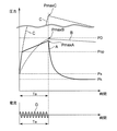
図4は内部アーク発生時の密閉タンク12内の圧力変化の状態を示す図である。特に、図4に示す上段のグラフにおいて、横軸に時間、縦軸に圧力を示し、絶縁ガス15の異なる種類ごとに内部アークの対象ガス区分111における圧力特性を示す。また、図4に示す下段のグラフにおいて、横軸に時間、縦軸に電流を示し、上段のグラフと同一時間に対応する内部アークの電流特性を示す。以下に、密閉タンク12内で内部アークが発生した際の、密閉タンク12内の圧力変化について、図4を用いて説明する。
FIG. 4 is a diagram showing a state of pressure change in the
例えば、図1に示す第1の実施形態における電力用ガス絶縁機器において、絶縁ガス15がCO2ガス、N2ガス等であり、内部アーク(図1に示すアーク14)が発生したとする。内部アークの発生後に、密閉タンク12内の圧力は上昇する。この場合における圧力特性は図4に示す波形Aであり、内部アークの電流特性は波形Dであるとする。
For example, in the power gas insulating apparatus in the first embodiment shown in FIG. 1, it is assumed that the insulating
また、図4に示す波形Bは、波形Aと比較するために示すものであり、図1に示す同体積の密閉タンク12で、同じエネルギの内部アークが発生し、絶縁ガス15がSF6ガスとし、放圧装置2を備えないとした場合における圧力特性の一例である。
Further, a waveform B shown in FIG. 4 is shown for comparison with the waveform A, and an internal arc of the same energy is generated in the same volume sealed
同様に、図4に示す波形Cについても、波形Aと比較のために示すものであり、図1に示す同体積の密閉タンク12で、同じエネルギの内部アークが発生し、絶縁ガス15がCO2ガス、N2ガス等とし、放圧装置2を備えないとした場合における圧力特性の一例である。これらの内部アークは、波形Dに示すようにアーク継続時間Taが共通であるとする。なお、図4に示すPDは絶縁スペーサの耐圧力、同じくPopは放圧装置2の作動圧力、Psは密閉タンク12の定格圧力(通常時における密封圧力に相当)、Pkは大気圧を示すものとする。
Similarly, the waveform C shown in FIG. 4 is also shown for comparison with the waveform A. An internal arc of the same energy is generated in the same volume sealed
前述した放圧装置2を備えない電力用ガス絶縁機器では、絶縁ガス15をSF6ガスとし場合に、内部アーク発生後の圧力上昇特性は、図4の波形Bに示すように、耐圧力PDを超えない最大圧力PmaxBまで上昇し、その後、緩やかに下降している。
In the power gas-insulated equipment that does not include the
前述した放圧装置2を備えない電力用ガス絶縁機器では、絶縁ガス15をCO2ガス、N2ガス等とした場合、図4の波形Cに示すように、SF6ガスに比べて圧力が上昇している。すなわち、これらのガスはSF6ガスと比べると、密閉タンク12内の圧力はより急峻に、かつ高い圧力(最大圧力PmaxC)まで上昇する。このため、前述した課題の電力用ガス絶縁機器では、密閉タンク12内の最大圧力が耐圧力PDを超える恐れが生じ、密閉タンク12を破壊するなどの機器の環境性、安全性、経済性を損なうことになる。
In the above-described power gas insulation apparatus that does not include the
以上説明したように、圧力の上昇特性および放圧特性は、絶縁ガスの種類、機器の構成および内部アークの状況により大きく異なる。したがって、SF6ガスを用いた電力用ガス絶縁機器を、単に、CO2ガス、N2ガス等を用いる場合に適用したのでは、上述したような問題が発生する。 As described above, the pressure rise characteristic and the pressure release characteristic vary greatly depending on the type of insulating gas, the configuration of the equipment, and the state of the internal arc. Therefore, if the power gas insulation apparatus using SF 6 gas is applied simply when CO 2 gas, N 2 gas or the like is used, the above-described problems occur.
一方、第1の実施形態における電力用ガス絶縁機器では、前述の(式1)の条件を満たすように作動圧力Popおよび最小流路断面積SDの範囲が適切に定められ、密閉タンク12における異常時の圧力上昇を、耐圧力PDを超えないように抑制することができる。すなわち、図4に示す波形Aのように、内部アークの発生後、定格圧力Psから圧力が急上昇しても、最大圧力PmaxAが絶縁スペーサの耐圧力PDを超えないようにされている。
On the other hand, in the power gas insulation apparatus according to the first embodiment, the range of the operating pressure Pop and the minimum flow path cross-sectional area SD is appropriately determined so as to satisfy the condition of (Expression 1) described above, and an abnormality in the sealed
これにより、第1の実施形態では、絶縁ガス15をN2、CO2等にした場合においても、密閉タンク12における対象ガス区分111の圧力は内部アーク発生と同時に急峻に上昇するものの、作動圧力Popを超えると放圧装置2が作動して、対象ガス区分111の圧力を急速に低下させ、かつ、耐圧力PDを超えない最大圧力PmaxAに抑制することができる。
Thereby, in the first embodiment, even when the insulating
具体的には、図2および図3に示す放圧装置2aでは、対象ガス区分111の圧力が作動圧力Popを超える異常時に、破裂板22が破裂する。これにより、密閉タンク12の対象ガス区分111は、流路口21における最小流路断面積SDを介して大気17と連通する。このため、放圧装置2aの放圧作動後には、図4の波形Dに示すように対象ガス区分111における内部アークが時間Taの間に継続しながらも、図4の波形Aに示すように対象ガス区分111の圧力上昇の速度は緩和される。時間Taの経過後、内部アークが消滅して、対象ガス区分111の圧力は時間とともに大気圧Pk近傍まで低下する。このように、絶縁ガス15としてN2、CO2等を使用した場合でも、第1の実施形態による電力用ガス絶縁機器において、異常時に密閉タンク12における対象ガス区分111の圧力が耐圧力PDを超えることを回避することができ、安全性が確保される。
Specifically, in the
ここで、(式1)の根拠について以下に説明する。密閉タンク12で内部アークが発生した場合の圧力上昇特性、および放圧装置2の放圧特性は、すべての物理定数や境界条件を正確に得られれば理論上は算出可能であるが、現実的にはこれらの全条件を正確に把握するのは困難である。また、たとえ理論式を導出しても非常に複雑な関数となり、工学上の利用も困難である。そこで、内部アークの点弧時間Ta経過後、密閉タンク12内の対象ガス区分111の最大圧力Pmaxを求めるため、理論式に基づいて、下記の経験的係数を含む経験式を立案した。
Here, the basis of (Formula 1) will be described below. The pressure rise characteristics when an internal arc is generated in the sealed
Kc=Kga×Iaα/VTとする場合に、
Pmax=Pop+(Kc×Ta−Pop)×{1−e−(VT/Kgb/SD)} ・・・(式2)
なお、(式2)の式中の各変数、およびその単位については、(式1)で記載したものと同一である。以下に、(式2)の経験式としての妥当性を示す。
When Kc = Kga × Ia α / VT,
Pmax = Pop + (Kc * Ta-Pop) * {1-e- (VT / Kgb / SD) } (Formula 2)
In addition, each variable in the formula of (Formula 2) and its unit are the same as those described in (Formula 1). The validity of (Expression 2) as an empirical expression is shown below.
図5は放圧装置2における最小流路断面積SDと対象ガス区分111の最大圧力との関係の一例を示す。具体的には、図5において、縦軸は最大圧力Pmax(MPa)、横軸は最小流路断面積SD(m2)であり、内部アークの電流実効値Ia=50kAの条件における、充填ガス種類ごとにPmaxとSDとの関係を(式2)で求めた近似値と、実測値との一例を示すものである。なお、図5では、SF6ガス、CO2ガス、N2ガスの充填ガス種類ごとにそれぞれについて、(式2)で求めた曲線と、実測値とをあわせて示している。
FIG. 5 shows an example of the relationship between the minimum flow path cross-sectional area SD and the maximum pressure of the
(式2)では、充填ガスによる違いは、KgaおよびKgbの二つの定数にて規定されている。例えば、N2ガスを主成分とする場合、KgaおよびKgbがそれぞれ14.2および600である。CO2ガスを主成分とする場合にはそれぞれ7.70および400である。図5に示すように、(式2)で求めた値は、実測値とよく近似していることがわかる。すなわち、(式2)に示す簡便な式により、充填ガスの種類が異なっても、最大圧力Pmaxを容易に把握することができる。 In (Expression 2), the difference depending on the filling gas is defined by two constants of Kga and Kgb. For example, when N 2 gas is the main component, Kga and Kgb are 14.2 and 600, respectively. When CO 2 gas is the main component, they are 7.70 and 400, respectively. As shown in FIG. 5, it can be seen that the value obtained by (Equation 2) closely approximates the actual measurement value. In other words, the maximum pressure Pmax can be easily grasped by the simple expression shown in (Expression 2) even if the type of the filling gas is different.
第1の実施形態の電力用ガス絶縁機器によれば、密閉タンク12内の最大圧力Pmaxが耐圧力PDを超えない範囲で、最小流路断面積SDを適正に設定することができる。例えば、図5に示す例において、充填ガスをCO2ガスとし、耐圧力PDが1.5(MPa)である設計Eとする。図5に示すように、設計Eでは、最小流路断面積SDを概ね0.0022(m2)以上にする必要があり、それを下回ると安全性不足の設計とされる。
According to the power gas insulation apparatus of the first embodiment, the minimum flow path cross-sectional area SD can be appropriately set within a range in which the maximum pressure Pmax in the sealed
一方、最小流路断面積SDについて0.0022(m2)を大きく超えるような過剰設計とすると、それに伴う容器の密封性を保つための構造的なコストがかかるため、安全性と経済性を考慮して最小流路断面積SDの値を設定すればよい。この際に、安全性を確保するための最小流路断面積SDの範囲を定めるのが(式1)であり、この(式1)は(式2)においてPD>Pmaxとする条件を適用することにより導出される。 On the other hand, if the overflow design greatly exceeds 0.0022 (m 2 ) with respect to the minimum flow path cross-sectional area SD, the structural cost for maintaining the hermeticity of the container is increased. The value of the minimum channel cross-sectional area SD may be set in consideration. At this time, the range of the minimum flow path cross-sectional area SD for ensuring safety is defined by (Expression 1), and (Expression 1) applies the condition of PD> Pmax in (Expression 2). Is derived.
このように、充填ガスとして、CO2、N2、または、これらを主成分とした絶縁ガス15などを適用した場合、(式1)を用いて最小流路断面積SDの値を適正に設定することができるため、充填ガスの種類が異なっても、図4に示す波形Aのように、最大圧力PmaxAが耐圧力PDを超えないようにすることができる。これにより、電力用ガス絶縁機器の安全性と経済性を容易に達成することができる。
In this way, when CO 2 , N 2 , or the insulating
以上説明したように、最小流路断面積SDに基づいて放圧装置2の放圧を開始する作動圧力Popを定めることができる。または、作動圧力Popに基づいて最小流路断面積SDが定めることができ、もしくは、この2つの値を調整して定めることができる。これにより、放圧装置2は、アーク発生対象となるガス区分(対象ガス区分111)における圧力が作動圧力Popを超えた場合に、密閉タンク12を放圧する。一方、対象ガス区分111における圧力が作動圧力Popを超えない場合に、密閉タンク12を密封して保持する。
As described above, the operating pressure Pop at which the
第1の実施形態によれば、保護カバー20により噴出ガスが安全な方向に噴出されるため、高温・高圧の噴出ガスが周囲に危険を及ぼすことを回避することができる。また、放圧時の破裂板22の散乱等に対する安全性を考慮することができる。これにより、内部アークの発生後、放圧装置2は、圧力上昇の異常時においても、安全に絶縁ガス15を大気17へ放出することができる。
According to the first embodiment, since the ejection gas is ejected in a safe direction by the
第1の実施形態によれば、絶縁ガス15としてSF6ガスを使用せずに、安全設計を考慮して、N2ガスあるいはCO2ガス単体、もしくはN2ガスあるいはCO2ガスを主成分とする(例えば圧力比で50%以上含む)ガスなどを使用することができる。また、密閉タンク12に充填する絶縁ガス15は、何らかの処理回収されたCO2ガスを利用してもよい。この場合には、環境保護において優れたものとなる。これらのガスを使用することで、環境性能に優れた電力用ガス遮断器を提供することが可能である。
According to the first embodiment, SF 6 gas is not used as the insulating
また、第1の実施形態による電力用ガス絶縁機器によれば、N2ガス、CO2ガスなどの絶縁ガス15を用いるため、内部アークが発生しても、SF6ガスとは異なり危険な分解生成物は発生しない。また、放圧時の噴出ガス、破裂板22の散乱等に対する安全性が考慮されているため、放圧装置2は、圧力上昇の異常時においても、安全に絶縁ガス15を大気17へ放出することができる。
Further, according to the power gas insulation apparatus according to the first embodiment, since the insulating
密閉タンク12は、好ましくは、鋳造で製作されたものではなく、圧延された板材を溶接して加工されたタンクである。これにより、密閉タンク12において、内部アークによる局所的な加熱や、密閉タンク12内のガス圧の過剰な上昇による異常圧力が発生した場合であっても、タンク全体が爆発飛散するリスクは低くなり、さらに安全性が高められる。
The sealed
以上説明した通り、第1の実施形態によれば、環境性、安全性、経済性に優れた電力用ガス絶縁機器を提供することができる。 As described above, according to the first embodiment, it is possible to provide a gas insulating device for electric power that is excellent in environmental performance, safety, and economy.
[第2の実施形態]
図6および図7は第2の実施形態における放圧装置2bの拡大縦断面図である。特に、図6は通常時の放圧装置2bにおける拡大縦断面図、同様に、図7は異常時の拡大縦断面図である。第2の実施形態は、第1の実施形態と以下の点に相違がある。
[Second Embodiment]
6 and 7 are enlarged longitudinal sectional views of the
第2の実施形態において、図示しない電力用ガス絶縁機器の基本的な構成は、第1の実施形態における放圧装置2a以外は第1の実施形態と同様である。放圧装置2bは、保護カバー20と、流路口21と、弁体24と、ばね25と、を有する。図6および図7に示すように、放圧装置2bでは、ばね25が弁体24を付勢する構造とされている。
In the second embodiment, the basic configuration of a power gas insulation device (not shown) is the same as that of the first embodiment except for the
弁体24は、流路口21を閉塞および開口するための弁構造を有し、密閉タンク12の内側または外側から移動可能とされる。弁体24は、流路口21の開口を閉じるような形状に形成されている。なお、図6および図7では、密閉タンク12の外側から、弁体24が流路口21を閉塞および開口可能な構造の一例を示しているが、密閉タンク12の内側から、弁体24が流路口21を閉塞および開口可能な構造であってもよい。
The
ばね25は、弁体24を付勢するために、一端が弁体24に取り付けられ、他端が支持部材に固定される。例えば、図6および図7に示すように、保護カバー20を支持部材として併用してもよいし、保護カバー20とは別な支持部材であってもよい。
The
詳しくは、後述するように、ばね25と一体構造とされた弁体24が、通常時には流路口21を閉塞して密閉タンク12を密封し、異常時には流路口21を開口して密閉タンク12を放圧する。
Specifically, as will be described later, the
図6に示すように、密閉タンク12の対象ガス区分111における圧力が作動圧力Popを超えない通常時には、流路口21を閉じる側に弁体24を付勢するばね25の反発力により、弁体24が流路口21を閉じている。
As shown in FIG. 6, when the pressure in the
図7に示すように、密閉タンク12の対象ガス区分111における圧力が作動圧力Popを超えた異常時には、流路口21を開く側に弁体24を付勢するばね25が変位し、ばね25の反発力と当該圧力とが均衡した状態で、弁体24が流路口21を開いている。これにより、流路口21の外側では、弁体24と流路口21との間に空隙211が生じる。この空隙211を介して、密閉タンク12の内側と外側とが連通されて、絶縁ガス15が大気17へ放出される。すなわち、放圧装置2bにより密閉タンク12が放圧される。
As shown in FIG. 7, when the pressure in the
図7に示す例において、流路口21の空隙211における最小流路断面積をSV(m2)とする。なお、この最小流路断面積SVは、前述の(式1)におけるSDをSVに置き換えた式で規定されるものとする。ここで、空隙211の最小流路断面積SVは、流路口21での絶縁ガス15の流出方向(図7に示す矢印方向)に対して垂直の断面における最小断面積である。絶縁ガス15が、この空隙211を介して、密閉タンク12の内側から外側へ放出される。
In the example shown in FIG. 7, the minimum channel cross-sectional area in the
保護カバー20は、流路口21の外側の特定方向への噴出ガスの飛散を回避するために、密閉タンク12に取り付けられる。この保護カバー20により一部の噴出方向の噴出ガスは、その噴出方向を変えられる。密閉タンク12に保護カバー20を取り付けることにより、噴出ガスなどが安全上問題となる場所に噴出することを防止する。
The
第2の実施形態は、第1の実施形態における放圧装置2aの破裂板22と比べて、放圧装置2bのばね25の弾性係数に応じて、作動圧力Popを調節可能である。
Compared with the
また、第1の実施形態の場合、放圧動作後に密閉タンク12内の圧力は大気圧まで低下するが、第2の実施形態の場合、密閉タンク12内の圧力は初期の充填圧力相当は保たれる。このため、放圧動作後も電気絶縁性が確保されやすい。
In the case of the first embodiment, the pressure in the
一方で、図7に示す第2の実施形態における放圧装置2bの場合には、放圧動作時にできる空隙211の最小流路断面積SVは、図3に示す第1の実施形態における放圧装置2aの最小流路断面積SDと比べて、大きく確保することが困難である。そのため、第2の実施形態は、比較的にアーク電流の平均実効値Ia、アークの点弧時間Ta、アークが発生しているガス区分のタンク容積VTなどが小さい用途の場合に適している。
On the other hand, in the case of the
第2の実施形態によれば、内部アークによる絶縁ガス15の異常時の圧力上昇の際に、密閉タンク12の対象ガス区分111における圧力が作動圧力Popを超えると、放圧装置2bは放圧動作に移行する。すなわち、放圧装置2bは、流路口21を閉塞する状態から開口する状態へ移行する。また、密閉タンク12における対象ガス区分111の圧力が作動圧力Popを超えてから当該圧力値を下回ると、弁体24は、図7に示す流路口21を開口する状態から、図6に示す流路口21を閉塞する状態へ移行する。すなわち、放圧装置2bは、密閉タンク12における対象ガス区分111の圧力に応じて、流路口21を開口する状態と閉塞する状態との間を切り換えることができる。
According to the second embodiment, when the pressure in the
第2の実施形態によれば、絶縁ガス15に、CO2,N2ガス、これらを主成分とした混合ガスなどを使用した場合にも、密閉タンク12における内部アークによる異常時の圧力上昇に対して、安全に放圧動作を行うことができる。これにより、密閉タンク12を必要以上に過大な容積とすることや、過渡に頑丈な構造を採用することを回避できるため、設置スペース、製造コスト等の負担を軽減することができる。また、第2の実施形態では、放圧装置2bに弁体およびばねを用いるため、異常発生後に部品交換を必要としないため、保守コスト等を削減することができる。
According to the second embodiment, even when CO 2 , N 2 gas, or a mixed gas containing these as main components is used as the insulating
以上説明したように、第2の実施形態の電力用ガス絶縁機器によれば、環境性、安全性、経済性に優れた電力用ガス絶縁機器を提供することができる。 As described above, according to the power gas insulation apparatus of the second embodiment, it is possible to provide a power gas insulation apparatus excellent in environmental performance, safety, and economy.
[第3の実施形態]
図8は第3の実施形態における電力用ガス絶縁機器の縦断面図である。図8に示す第3の実施形態の電力用ガス絶縁機器の基本的な構成は、第1および第2の実施形態の電力用ガス絶縁機器と同じであるが、下記の点に相違がある。
[Third Embodiment]
FIG. 8 is a longitudinal cross-sectional view of a power gas insulation apparatus according to the third embodiment. The basic configuration of the power gas insulation apparatus of the third embodiment shown in FIG. 8 is the same as that of the power gas insulation apparatus of the first and second embodiments, but there are differences in the following points.
図8に示す例において、対象ガス区分111に隣接するガス区分は隣接ガス区分112であり、絶縁スペーサ11aは、対象ガス区分111と隣接ガス区分112との間に配置され、その耐圧力は密閉タンク12よりも弱い強度とされ、かつ、放圧装置2の作動圧力Popを超えると破裂する強度とされる。
In the example shown in FIG. 8, the gas section adjacent to the
絶縁スペーサ11bは、隣接ガス区分112と隣接する他のガス区分との間に配置され、その耐圧力は密閉タンク12よりも弱い強度とされ、かつ、絶縁スペーサ11aの耐圧力よりも強い強度とされる。
The insulating
さらに、流路口21での絶縁ガス15の流出方向に対して垂直の断面における最小流路断面積をSDとし、放圧装置2が放圧を開始する作動圧力をPopとして、密閉タンク12の内側で発生するアークについて、推定値としたアーク電流の平均実効値をIa、推定値としたアークの点弧時間をTa、対象ガス区分111の容積をVT、対象ガス区分111と隣接する隣接ガス区分112の体積Vn、対象ガス区分111に配置される絶縁スペーサ11a以外の絶縁スペーサ11bの耐圧力をPD、アークのエネルギが圧力上昇に寄与する効率を示す定数をα、絶縁ガスによる圧力上昇特性を規定する第1の定数をKga、絶縁ガスによる放圧特性を規定する第2の定数をKgbとし、Kc=Kga×Iaα/(VT+Vn)とする。
Further, the inside of the
この場合に、放圧装置2におけるSDおよびPopは、
SD>(VT+Vn)/{Kgb×log((Kc×Ta−Pop)/(Kc×Ta−PD))} (式3)
の条件式を満足する範囲にある。
In this case, SD and Pop in the
SD> (VT + Vn) / {Kgb × log ((Kc × Ta−Pop) / (Kc × Ta−PD))} (Formula 3)
It is in the range that satisfies the conditional expression.
これにより、密閉タンク12の対象ガス区分111に配置される絶縁スペーサ11aは、対象ガス区分111における圧力が作動圧力Popを超えない通常時には破裂せず、対象ガス区分111における圧力が作動圧力Popを超えた異常時には破裂する。一方、絶縁スペーサ11bは、その耐圧力は密閉タンク12よりも弱い強度とされ、かつ、絶縁スペーサ11aの耐圧力よりも強い強度とされるため、作動圧力Popを大きく超える圧力値でない限り、異常時においても絶縁スペーサ11bは破裂しない。
Thereby, the insulating
したがって、第3の実施形態による電力用ガス絶縁機器において、内部アークが発生し、当該対象ガス区分111の圧力が絶縁スペーサ11aの耐圧力(許容圧力)を超える圧力になると、当該絶縁スペーサ11aは破損する。この破損後における、当該対象ガス区分111と隣接ガス区分112とを足し合わせたガス区分が、新たな同一の対象ガス区分となる。
Accordingly, in the power gas insulation apparatus according to the third embodiment, when an internal arc is generated and the pressure of the
第3の実施形態の例では、例えばアーク14が発生する当初の対象ガス区分111の容積VTが小さく、(式1)で規定される範囲での構成が困難な場合に、絶縁スペーサ11aの破損を容認する代わりに、実効的に容積VTを容積(VT+Vn)までに大きくし、異常時の圧力上昇を抑制することができる。さらに、圧力上昇値が耐圧力PDを超過しないように、放圧装置2が放圧動作を行うことができる。これにより、高温・高圧のガスが大気に放出されるが、実効的な密閉タンク12のアークの発生対象とするガス区分の容積(VT+Vn)が増大されるので、異常時の圧力上昇は緩和され、密閉タンク12を破壊するような周囲に及ぼす危険性を低下させることができる。
In the example of the third embodiment, for example, when the volume VT of the initial
また、隣接ガス区分112と隣接する他の隣接ガス区分との間に、さらに、絶縁スペーサ11bに代えて絶縁スペーサ11aを配置させてもよい。この区間に配置された絶縁スペーサ11aも破損した場合に、対象ガス区分111の容積VTおよび隣接ガス区分112の容積Vnに加えて、当該隣接する他のガス区分の容積を加えた合計値が、前述の(式1)などのVTに相当するものとなる。
Further, an insulating
このように、2以上のガス区分に絶縁スペーサ11aを配置することにより、さらに、前述の(式1)のVTに相当する容積を実効的に増大させることができる。
As described above, by disposing the insulating
以上のように、第3の実施形態では、複数のガス区分ごとに絶縁スペーサ11aまたは絶縁スペーサ11bを配置して隣接ガス区分を複数設けたことを特徴とする。これにより、密閉タンク12のアーク発生対象のガス区分(当初の対象ガス区分111)の容積を大きくすることができない場合や、構造的に耐圧力の強度を高めることができない場合等においても、実効的にアーク発生対象のガス区分の容積を増大させることができるため、異常時の内部圧力の上昇を抑制することができる。また、絶縁ガス15の大気への放出を極力抑えることができる。
As described above, the third embodiment is characterized in that the insulating
以上説明したように、第3の実施形態の電力用ガス絶縁機器によれば、環境性、安全性、経済性に優れた電力用ガス絶縁機器を提供することができる。 As described above, according to the power gas insulation apparatus of the third embodiment, it is possible to provide a power gas insulation apparatus excellent in environmental performance, safety, and economy.
なお、図8において、隣接ガス区分112は単純な単相母線だけでなく、断路器などのガス絶縁開閉装置の何らかの機器であってもよい。
In FIG. 8, the
[他の実施形態]
第3の実施形態における変形の実施形態として、(式1)における放圧装置の最小流路断面積SDが0以下でも構成可能な設計である場合に、放圧装置2を具備しないことができる。例えば、絶縁ガスを大気へ放出できない制約、規制等がある場合に、電力用ガス絶縁機器が放圧装置2を具備することができない。このような場合には、第3の実施形態における変形の実施形態として、絶縁スペーサ11aの耐圧力を第3の実施形態に述べたように定めて、かつ、放圧装置2を具備しない。これにより、前述したように、内部アーク発生時に、実効的なガス区分の容積を確保することができる。
[Other Embodiments]
As a modified embodiment of the third embodiment, the
以上、本発明のいくつかの実施形態を説明したが、これらの実施形態は、例として提示したものであり、発明の範囲を限定することは意図していない。例えば、電力用ガス絶縁機器以外でも、絶縁ガスを用いる同様の装置に適用してもよい。また、各実施形態の特徴を組み合わせてもよい。さらに、これらの実施形態は、その他の様々な形態で実施されることが可能であり、発明の要旨を逸脱しない範囲で、種々の省略、置き換え、変更を行うことができる。これら実施形態やその変形には、発明の範囲や要旨に含まれると同様に、特許請求の範囲に記載された発明とその均等の範囲に含まれるものである。 As mentioned above, although some embodiment of this invention was described, these embodiment is shown as an example and is not intending limiting the range of invention. For example, the present invention may be applied to a similar apparatus using an insulating gas other than the power gas insulating apparatus. Moreover, you may combine the characteristic of each embodiment. Furthermore, these embodiments can be implemented in various other forms, and various omissions, replacements, and changes can be made without departing from the scope of the invention. These embodiments and modifications thereof are included in the invention described in the claims and equivalents thereof as well as included in the scope and gist of the invention.
1…ガス遮断器、2、2a、2b…放圧装置、3…高電圧導体、11、11a、11b…絶縁スペーサ、12…密閉タンク、14…アーク、15…絶縁ガス、17…大気、20…保護カバー、21…流路口、22…破裂板、23…留め具、24…弁体、25…ばね、111…対象ガス区分、112…隣接ガス区分、191、192…矢印方向、211…空隙
DESCRIPTION OF
Claims (8)
絶縁ガスが充填される密閉容器と、
前記密閉容器を複数のガス区分に区画するとともに、前記高電圧導体と前記密閉容器との間の絶縁を保持しながら前記高電圧導体を支持する絶縁スペーサと、
前記密閉容器の内側と外側へ連通された流路口が設けられ、当該流路口を閉じることにより前記密閉容器を密封し、当該流路口を開くことにより前記密閉容器を放圧する放圧装置と、
を具備する電力用ガス絶縁機器において、
前記流路口での前記絶縁ガスの流出方向に対して垂直の断面における最小流路断面積をSDとし、前記放圧装置が放圧を開始する作動圧力をPopとして、前記密閉容器の内側で発生するアークについて、推定値としたアーク電流の平均実効値をIa、推定値としたアークの点弧時間をTa、前記アークの発生対象とするガス区分の容積をVT、前記絶縁スペーサの耐圧力をPD、前記アークのエネルギが圧力上昇に寄与する効率を示す定数をα、前記絶縁ガスによる圧力上昇特性を規定する第1の定数をKga、前記絶縁ガスによる放圧特性を規定する第2の定数をKgbとし、Kc=Kga×Iaα/VTとする場合に、
SD>VT/{Kgb×log((Kc×Ta−Pop)/(Kc×Ta−PD))}
の条件式を満足する範囲にあり、
前記放圧装置は、前記アークの発生対象とするガス区分における圧力が前記作動圧力を超えない通常時に前記密閉容器を密封して保持し、前記アークの発生対象とするガス区分における圧力が前記作動圧力を超えた異常時に前記密閉容器を放圧する
ことを特徴とする電力用ガス絶縁機器。 High voltage conductors to be charged,
A sealed container filled with insulating gas;
Partitioning the sealed container into a plurality of gas sections, and an insulating spacer that supports the high-voltage conductor while maintaining insulation between the high-voltage conductor and the sealed container;
A pressure relief device that is provided with a flow path port that communicates with the inside and the outside of the sealed container, seals the sealed container by closing the flow path port, and depressurizes the sealed container by opening the flow path port;
In the gas insulation device for electric power comprising
Generated inside the hermetic container with SD as the minimum flow path cross-sectional area in the cross section perpendicular to the outflow direction of the insulating gas at the flow path opening, and Pop as the operating pressure at which the pressure release device starts releasing pressure. For the arc to be generated, the average effective value of the arc current as an estimated value is Ia, the ignition time of the arc as an estimated value is Ta, the volume of the gas segment for which the arc is generated is VT, and the pressure resistance of the insulating spacer is PD, a constant indicating the efficiency with which the energy of the arc contributes to the pressure increase, α, a first constant defining the pressure increase characteristic due to the insulating gas, Kga, and a second constant defining the pressure release characteristic due to the insulating gas Is Kgb and Kc = Kga × Ia α / VT,
SD> VT / {Kgb * log ((Kc * Ta-Pop) / (Kc * Ta-PD))}
In a range that satisfies the conditional expression
The pressure relief device seals and holds the hermetic container at a normal time when the pressure in the gas section to be generated by the arc does not exceed the operating pressure, and the pressure in the gas section to be generated by the arc A gas insulating device for electric power, wherein the airtight container is released in the event of an abnormality exceeding the pressure.
前記破裂板は、前記アークの発生対象とするガス区分に配置される前記絶縁スペーサの耐圧力より弱くされ、かつ、前記異常時に破裂する強度である
ことを特徴とする請求項1に記載の電力用ガス絶縁機器。 The pressure relief device has a rupturable plate that covers the flow path port of the sealed container so as to close it,
2. The electric power according to claim 1, wherein the rupturable plate has a strength that is weaker than a pressure resistance of the insulating spacer arranged in the gas section to be the target of the arc and bursts at the time of the abnormality. Gas insulation equipment.
前記通常時に前記弾性体の付勢力により前記弁体が前記流路口を閉鎖しており、前記異常時に前記弾性体が縮んで、前記弁体が前記流路口を開く位置まで移動する
ことを特徴とする請求項1に記載の電力用ガス絶縁機器。 The pressure relief device includes a valve body that closes the flow path port, and an elastic body that biases the valve body toward the side that closes the flow path port.
The valve body closes the flow path opening by the urging force of the elastic body at the normal time, the elastic body contracts at the time of the abnormality, and the valve body moves to a position where the flow path opening opens. The gas insulation device for electric power according to claim 1 to do.
ことを特徴とする請求項1ないし請求項3のいずれか一項に記載の電力用ガス絶縁機器。 The said pressure release apparatus has a protective cover provided in the outer side of the said airtight container in order to change the ejection direction of the said insulating gas when the said airtight container is depressurized. The gas insulation device for electric power according to any one of 3.
SDb>(VT+Vn)/{Kgb×log((Kcb×Ta−Pop)/(Kcb×Ta−PDb))}
の条件式を満足する範囲にあり、前記アークの発生対象とするガス区分における圧力が前記作動圧力を超えない通常時には破裂せず、前記アークの発生対象とするガス区分における圧力が前記作動圧力を超えた異常時には破裂する
ことを特徴とする請求項1ないし請求項4のいずれか一項に記載の電力用ガス絶縁機器。 Among the insulating spacers divided into the plurality of gas sections, at least the insulating spacer disposed in the gas section to be subjected to arc generation inside the sealed container is weaker than the pressure resistance of the sealed container, and SDb is the minimum flow path cross-sectional area in the cross section perpendicular to the outflow direction of the insulating gas in the insulating spacer arranged in the gas section that is the target of arc generation inside the sealed container, and is the target of arc generation. The pressure resistance of an insulating spacer other than the insulating spacer arranged in the gas section is PDb, the volume of the gas section adjacent to the arc generation target is Vn, and Kcb = Kga × Ia α / (VT + Vn) If you want to
SDb> (VT + Vn) / {Kgb × log ((Kcb × Ta−Pop) / (Kcb × Ta−PDb))}
The pressure in the gas section subject to arc generation does not exceed the operating pressure, and the pressure in the gas section targeted for arc generation does not exceed the operating pressure. The gas insulation device for electric power according to any one of claims 1 to 4, wherein the electric power gas insulation device bursts when the abnormality is exceeded.
絶縁ガスが充填される密閉容器と、
前記密閉容器を複数のガス区分に区画するとともに、前記高電圧導体と前記密閉容器との間の絶縁を保持しながら前記高電圧導体を支持する絶縁スペーサと、
前記密閉容器の内側と外側へ連通された流路口が設けられ、当該流路口を閉じることにより前記密閉容器を密封し、当該流路口を開くことにより前記密閉容器を放圧する放圧装置と、
を具備する電力用ガス絶縁機器において、
前記複数のガス区分に区画する絶縁スペーサの中で、少なくとも、前記密閉容器の内側でアークの発生対象とするガス区分に配置される絶縁スペーサは、前記密閉容器の耐圧力より弱くされ、かつ、前記流路口での前記絶縁ガスの流出方向に対して垂直の断面における最小流路断面積をSDとし、前記放圧装置が放圧を開始する作動圧力をPopとして、前記密閉容器の内側で発生するアークについて、推定値としたアーク電流の平均実効値をIa、推定値としたアークの点弧時間をTa、前記アークの発生対象とするガス区分の容積をVT、前記アークの発生対象とするガス区分と隣接するガス区分の体積Vn、前記アークの発生対象とするガス区分に配置される絶縁スペーサ以外の絶縁スペーサの耐圧力をPD、前記アークのエネルギが圧力上昇に寄与する効率を示す定数をα、前記絶縁ガスによる圧力上昇特性を規定する第1の定数をKga、前記絶縁ガスによる放圧特性を規定する第2の定数をKgbとし、Kc=Kga×Iaα/(VT+Vn)とする場合に、
SD>(VT+Vn)/{Kgb×log((Kc×Ta−Pop)/(Kc×Ta−PD))}
の条件式を満足する範囲にあり、前記アークの発生対象とするガス区分における圧力が前記作動圧力を超えない通常時には破裂せず、前記アークの発生対象とするガス区分における圧力が前記作動圧力を超えた異常時には破裂する
ことを特徴とする電力用ガス絶縁機器。 High voltage conductors to be charged,
A sealed container filled with insulating gas;
Partitioning the sealed container into a plurality of gas sections, and an insulating spacer that supports the high-voltage conductor while maintaining insulation between the high-voltage conductor and the sealed container;
A pressure relief device that is provided with a flow path port that communicates with the inside and the outside of the sealed container, seals the sealed container by closing the flow path port, and depressurizes the sealed container by opening the flow path port;
In the gas insulation device for electric power comprising
Among the insulating spacers divided into the plurality of gas sections, at least the insulating spacer disposed in the gas section to be subjected to arc generation inside the sealed container is weaker than the pressure resistance of the sealed container, and Generated inside the hermetic container with SD as the minimum flow path cross-sectional area in the cross section perpendicular to the outflow direction of the insulating gas at the flow path opening, and Pop as the operating pressure at which the pressure release device starts releasing pressure. For the arc to be generated, the average effective value of the arc current as the estimated value is Ia, the ignition time of the arc as the estimated value is Ta, the volume of the gas segment that is the generation target of the arc is VT, and the generation target of the arc is The volume Vn of the gas section adjacent to the gas section, the pressure resistance of an insulating spacer other than the insulating spacer disposed in the gas section to be generated by the arc, PD, and the energy of the arc The constant indicating the efficiency contributing to the force increase is α, the first constant defining the pressure rise characteristic due to the insulating gas is Kga, the second constant defining the pressure release characteristic due to the insulating gas is Kgb, and Kc = Kga In the case of × Ia α / (VT + Vn),
SD> (VT + Vn) / {Kgb × log ((Kc × Ta−Pop) / (Kc × Ta−PD))}
The pressure in the gas section subject to arc generation does not exceed the operating pressure, and the pressure in the gas section targeted for arc generation does not exceed the operating pressure. Gas insulation equipment for electric power, which bursts when an abnormal condition is exceeded.
ことを特徴とする請求項1ないし請求項6のいずれか一項に記載の電力用ガス絶縁機器。 The insulating gas is any one of N 2 gas, CO 2 gas, a mixed gas containing N 2 gas as a main component, and a mixed gas containing CO 2 gas as a main component. The gas insulation apparatus for electric power as described in any one of 6.
ことを特徴とする請求項1ないし請求項7のいずれか一項に記載の電力用ガス絶縁機器の製造方法。 Method of manufacturing the power gas-insulated apparatus according to any one of claims 1 to 7 by welding pressure cast a plate member and forming the closed container.
Priority Applications (7)
| Application Number | Priority Date | Filing Date | Title |
|---|---|---|---|
| JP2011255049A JP5872260B2 (en) | 2011-11-22 | 2011-11-22 | Gas insulation device for electric power and its manufacturing method |
| KR1020127030371A KR101413344B1 (en) | 2011-11-22 | 2012-09-06 | Gas insulated electrical equipment |
| BR112014012260A BR112014012260A2 (en) | 2011-11-22 | 2012-09-06 | gas insulated electrical equipment |
| PCT/JP2012/005650 WO2013076892A1 (en) | 2011-11-22 | 2012-09-06 | Gas-insulated device for electrical use |
| EP12850866.0A EP2784886B1 (en) | 2011-11-22 | 2012-09-06 | Gas-insulated device for electrical use |
| CN201280001407.5A CN103229374B (en) | 2011-11-22 | 2012-09-06 | Electric power air insulating device |
| US14/276,677 US9258917B2 (en) | 2011-11-22 | 2014-05-13 | Gas insulated electrical equipment |
Applications Claiming Priority (1)
| Application Number | Priority Date | Filing Date | Title |
|---|---|---|---|
| JP2011255049A JP5872260B2 (en) | 2011-11-22 | 2011-11-22 | Gas insulation device for electric power and its manufacturing method |
Publications (2)
| Publication Number | Publication Date |
|---|---|
| JP2013110883A JP2013110883A (en) | 2013-06-06 |
| JP5872260B2 true JP5872260B2 (en) | 2016-03-01 |
Family
ID=48469364
Family Applications (1)
| Application Number | Title | Priority Date | Filing Date |
|---|---|---|---|
| JP2011255049A Active JP5872260B2 (en) | 2011-11-22 | 2011-11-22 | Gas insulation device for electric power and its manufacturing method |
Country Status (7)
| Country | Link |
|---|---|
| US (1) | US9258917B2 (en) |
| EP (1) | EP2784886B1 (en) |
| JP (1) | JP5872260B2 (en) |
| KR (1) | KR101413344B1 (en) |
| CN (1) | CN103229374B (en) |
| BR (1) | BR112014012260A2 (en) |
| WO (1) | WO2013076892A1 (en) |
Families Citing this family (7)
| Publication number | Priority date | Publication date | Assignee | Title |
|---|---|---|---|---|
| KR200484705Y1 (en) * | 2013-07-02 | 2017-10-18 | 엘에스산전 주식회사 | Gas Insulated Switchgear with Emission Means |
| JP2015056380A (en) * | 2013-09-13 | 2015-03-23 | 株式会社豊田自動織機 | Current interrupting device and power storage device using the same |
| CN105992736B (en) | 2014-02-19 | 2019-06-18 | 利乐拉瓦尔集团及财务有限公司 | Power supply unit |
| JP6457365B2 (en) * | 2015-09-14 | 2019-01-23 | 株式会社東芝 | Pressure vessel |
| KR200486519Y1 (en) * | 2016-08-16 | 2018-05-31 | 주식회사 서흥이엔지 | Valve for automatic section switch |
| GB2585026B (en) | 2019-06-25 | 2023-03-29 | Bae Systems Plc | Overpressure protection system for a magazine |
| KR102397195B1 (en) * | 2020-06-30 | 2022-05-12 | 한국전력공사 | Pressure reduction device of gas insulation switchgear |
Family Cites Families (17)
| Publication number | Priority date | Publication date | Assignee | Title |
|---|---|---|---|---|
| US3787648A (en) * | 1970-12-29 | 1974-01-22 | Fuji Electric Co Ltd | Tank-type gas-break circuit breaker |
| DE2739030C3 (en) * | 1977-08-26 | 1981-08-13 | Siemens AG, 1000 Berlin und 8000 München | Pressure relief device for a metal-enclosed, gas-insulated high-voltage system |
| DE3438635A1 (en) * | 1984-09-26 | 1986-04-03 | BBC Aktiengesellschaft Brown, Boveri & Cie., Baden, Aargau | EXHAUST GAS SWITCH |
| JPH027817A (en) * | 1988-06-15 | 1990-01-11 | Fuji Electric Co Ltd | Gas-sealed container for compressed-gas-insulated switchgear |
| FR2661776B1 (en) * | 1990-05-04 | 1996-05-10 | Merlin Gerin | INSTANT TRIGGER OF A CIRCUIT BREAKER. |
| JP2997027B2 (en) * | 1990-09-17 | 2000-01-11 | 株式会社日立製作所 | Gas insulated electrical equipment |
| JPH04133606A (en) * | 1990-09-25 | 1992-05-07 | Fuji Electric Co Ltd | Cubicle type gas insulated switching device |
| US5761025A (en) * | 1995-02-13 | 1998-06-02 | Iversen; Arthur H. | Low cost power switchgear |
| JPH09275609A (en) * | 1996-04-01 | 1997-10-21 | Mitsubishi Electric Corp | Pressure release duct of gas charge container |
| JP3008175B2 (en) * | 1996-04-12 | 2000-02-14 | 水道機工株式会社 | Gravity filtration device |
| FR2808118B1 (en) * | 2000-04-19 | 2004-06-18 | Alstom | SELF-BLOWING SWITCH WITH A TWO-VOLUME CUT-OFF CHAMBER |
| JP2003142318A (en) | 2001-11-01 | 2003-05-16 | Hitachi Ltd | Gas-insulated transformer |
| FR2868197B1 (en) * | 2004-03-25 | 2006-05-19 | Areva T & D Sa | CONTROL DEVICE FOR THE COORDINATED ACTUATION OF AT LEAST TWO SWITCHING APPARATUSES WHICH IS CUT-OFF IN THE VACUUM |
| JP4660407B2 (en) * | 2006-03-27 | 2011-03-30 | 株式会社東芝 | Gas insulated switch |
| DE602006012024D1 (en) * | 2006-05-29 | 2010-03-18 | Abb Technology Ag | Flask switch with a pressure relief valve |
| JP5127569B2 (en) | 2008-05-29 | 2013-01-23 | 株式会社東芝 | Gas insulated switch |
| FR2944134B1 (en) * | 2009-04-03 | 2014-08-29 | Schneider Electric Ind Sas | PRESSURIZED INSULATING ENVELOPE OF AN ELECTRICAL PROTECTION DEVICE |
-
2011
- 2011-11-22 JP JP2011255049A patent/JP5872260B2/en active Active
-
2012
- 2012-09-06 WO PCT/JP2012/005650 patent/WO2013076892A1/en active Application Filing
- 2012-09-06 EP EP12850866.0A patent/EP2784886B1/en active Active
- 2012-09-06 CN CN201280001407.5A patent/CN103229374B/en active Active
- 2012-09-06 KR KR1020127030371A patent/KR101413344B1/en active IP Right Grant
- 2012-09-06 BR BR112014012260A patent/BR112014012260A2/en not_active Application Discontinuation
-
2014
- 2014-05-13 US US14/276,677 patent/US9258917B2/en active Active
Also Published As
| Publication number | Publication date |
|---|---|
| BR112014012260A2 (en) | 2017-06-13 |
| US20140247538A1 (en) | 2014-09-04 |
| US9258917B2 (en) | 2016-02-09 |
| CN103229374B (en) | 2015-09-02 |
| KR101413344B1 (en) | 2014-06-27 |
| KR20130070603A (en) | 2013-06-27 |
| EP2784886B1 (en) | 2017-05-24 |
| WO2013076892A1 (en) | 2013-05-30 |
| EP2784886A1 (en) | 2014-10-01 |
| EP2784886A4 (en) | 2015-08-12 |
| CN103229374A (en) | 2013-07-31 |
| JP2013110883A (en) | 2013-06-06 |
Similar Documents
| Publication | Publication Date | Title |
|---|---|---|
| JP5872260B2 (en) | Gas insulation device for electric power and its manufacturing method | |
| MX2008004185A (en) | Arc flash elimination apparatus and method. | |
| KR101496903B1 (en) | Hybrid-extinction type gas circuit breaker | |
| RU2458425C2 (en) | High-voltage switch with disconnector function and method of switch control | |
| KR101109697B1 (en) | Apparatus for Hot Gas Exhaustion of Gas Insulation Switch | |
| EP3419039B1 (en) | Electric high-voltage circuit breaker | |
| US20210066011A1 (en) | Device for Interrupting an Electrical Current Circuit | |
| EP3570393B1 (en) | Switchgear | |
| EP3961668B1 (en) | Shut-off switch for gas insulated switchgear | |
| KR101386134B1 (en) | Self-blast type gas circuit breaker with pressure controllable thermal chamber | |
| JP2018523966A (en) | Improved disconnector and surge arrester including such disconnector | |
| US9018558B2 (en) | Gas circuit breaker | |
| CN204303602U (en) | Fast arc extinction device | |
| KR20120131266A (en) | Rupture disk cover of gas insulated switchgear | |
| WO2020208737A1 (en) | Pressure release device and gas insulated opening/closing device | |
| KR20130002471A (en) | Pressure relief apparatus of gas insulated switchgear | |
| JP2020508557A (en) | Safety fuse for low voltage applications | |
| CN107968348B (en) | Gas-insulated switchgear | |
| KR102108817B1 (en) | GIS breaker with ease of operation and insulated gas backflow prevention function | |
| EP3840005A1 (en) | Two way piston interrupter | |
| CN207572836U (en) | Gas insulation switch cabinet | |
| EP3531518A1 (en) | Exhaust gas duct for gas-insulated switchgear and gas-insulated switchgear having an exhaust gas duct | |
| JP2023113451A (en) | generator circuit breaker | |
| JP2021125886A (en) | Gas insulated switching device | |
| KR20150009761A (en) | Circuit breaker of gas insulation switchgear having double compression thermal chamber |
Legal Events
| Date | Code | Title | Description |
|---|---|---|---|
| RD01 | Notification of change of attorney |
Free format text: JAPANESE INTERMEDIATE CODE: A7421 Effective date: 20140110 |
|
| A621 | Written request for application examination |
Free format text: JAPANESE INTERMEDIATE CODE: A621 Effective date: 20141015 |
|
| A131 | Notification of reasons for refusal |
Free format text: JAPANESE INTERMEDIATE CODE: A131 Effective date: 20150901 |
|
| A521 | Written amendment |
Free format text: JAPANESE INTERMEDIATE CODE: A523 Effective date: 20151014 |
|
| TRDD | Decision of grant or rejection written | ||
| A01 | Written decision to grant a patent or to grant a registration (utility model) |
Free format text: JAPANESE INTERMEDIATE CODE: A01 Effective date: 20151215 |
|
| A61 | First payment of annual fees (during grant procedure) |
Free format text: JAPANESE INTERMEDIATE CODE: A61 Effective date: 20160113 |
|
| R151 | Written notification of patent or utility model registration |
Ref document number: 5872260 Country of ref document: JP Free format text: JAPANESE INTERMEDIATE CODE: R151 |