JP5870050B2 - System kitchen base cabinet - Google Patents
System kitchen base cabinet Download PDFInfo
- Publication number
- JP5870050B2 JP5870050B2 JP2013021153A JP2013021153A JP5870050B2 JP 5870050 B2 JP5870050 B2 JP 5870050B2 JP 2013021153 A JP2013021153 A JP 2013021153A JP 2013021153 A JP2013021153 A JP 2013021153A JP 5870050 B2 JP5870050 B2 JP 5870050B2
- Authority
- JP
- Japan
- Prior art keywords
- decorative panel
- base cabinet
- system kitchen
- absorbing material
- plate
- Prior art date
- Legal status (The legal status is an assumption and is not a legal conclusion. Google has not performed a legal analysis and makes no representation as to the accuracy of the status listed.)
- Active
Links
Images


Description
この発明は、対面型のシステムキッチン用のベースキャビネットに関する。 The present invention relates to a base cabinet for a face-to-face system kitchen.
近年は、ダイニングやリビングダイニングとキッチンとが完全に仕切られておらず、台所でシンクや調理台などに向かって立ったとき、身体がダイニングやリビングダイニング側を向くように設計された対面型のシステムキッチンによって、ダイニングやリビングダイニングと台所とが区画される場合がある。 In recent years, dining and living dining and the kitchen are not completely separated, and when facing the sink or cooking table in the kitchen, the face-to-face type is designed so that the body faces the dining or living-dining side Depending on the system kitchen, the dining room or living dining room may be separated from the kitchen.
ところで、近年のシステムキッチンのベースキャビネットには、食器洗濯乾燥機(以下、食洗機という。)やディスポーザー等が組み込まれることがあり、上述したような対面型のシステムキッチンの場合、食洗機からの食器洗浄音やディスポーザーからの破砕音等がダイニングやリビングダイニングに伝搬し、ダイニングで食事をしている人やリビングダイニングでくつろいでいる人に対して騒音になるといった問題がある。 By the way, a dishwasher (hereinafter referred to as a dishwasher), a disposer, or the like may be incorporated in a base cabinet of a recent system kitchen. In the case of the face-to-face system kitchen as described above, a dishwasher There is a problem that a dishwashing sound from a kitchen or a crushing sound from a disposer propagates to a dining room or a living dining room, resulting in noise for those who eat at the dining room or those who relax at the living dining room.
そこで、この発明の課題は、台所で発生した騒音がダイニングやリビングダイニング側に伝搬し難いシステムキッチンのベースキャビネットを提供することにある。 Accordingly, an object of the present invention is to provide a base cabinet for a system kitchen in which noise generated in the kitchen is difficult to propagate to the dining or living dining room side.
上記の課題を解決するため、請求項1に係る発明は、背板がダイニング側またはリビングダイニング側を向くように、ダイニング又はリビングダイニングと台所との間に配設される対面型のシステムキッチン用のベースキャビネットであって、前記背板の外面側に装飾パネルが取り付けられており、前記装飾パネルは、所定厚みを有する平板状の吸音材及び前記吸音材の端面を覆うように、前記吸音材を全周に渡って取り囲む枠材を有する心板と、前記心板の外表面及び端面を直接覆う布地とを備えており、前記枠材は、前記心板の外面側及び内面側の双方が開放されていることを特徴とするシステムキッチン用のベースキャビネットを提供するものである。
In order to solve the above-described problems, the invention according to
また、請求項2に係る発明は、請求項1に係る発明のシステムキッチン用のベースキャビネットにおいて、前記装飾パネルが側板の外面側にも取り付けられていることを特徴としている。
The invention according to
また、請求項3に係る発明は、請求項1または2に係る発明のシステムキッチン用のベースキャビネットにおいて、前記心板が、前記吸音材の外面側に配設された活性炭シートを備えていることを特徴としている。
The invention according to
また、請求項4に係る発明は、請求項1、2または3に係る発明のシステムキッチン用のベースキャビネットにおいて、前記心板が、その外面側を覆っている前記布地に隣接するように配設された光触媒シートを備えていることを特徴としている。 According to a fourth aspect of the present invention, in the base cabinet for a system kitchen according to the first, second or third aspect of the present invention, the core plate is disposed adjacent to the fabric covering the outer surface side. The photocatalyst sheet is provided.
以上のように、請求項1に係る発明のシステムキッチン用のベースキャビネットは、所定厚みを有する平板状の吸音材及び前記吸音材の端面を覆うように、前記吸音材を全周に渡って取り囲む、外面側及び内面側の双方が開放された枠材の内側に吸音材を配設してなる心板の外表面及び端面が布地によって直接覆われた装飾パネルを、背板の外面側に取り付けてあるので、ベースキャビネット内に、食洗機やディスポーザー等が組み込まれた場合であっても、食洗機からの食器洗浄音やディスポーザーからの破砕音等が装飾パネルの吸音材に吸音されることによって、ダイニング側またはリビングダイニング側に伝搬されにくく、ダイニングやリビングダイニングにおいて、食事をしたり、テレビを見たり、音楽を鑑賞したり、読書をしたりする際に、台所側の騒音が気にならないという効果が得られる。 As described above, the base cabinet for the system kitchen of the invention according to claim 1 surrounds the sound absorbing material over the entire circumference so as to cover the flat sound absorbing material having a predetermined thickness and the end surface of the sound absorbing material. attaching a decorative panel to the outer surface and the end surface is covered directly by the fabric of the heart plate both the external surface side and the inner surface side is by disposing the sound absorbing material on the inner side of the opened frame member, the outer surface side of the back plate Therefore, even when a dishwasher or disposer is installed in the base cabinet, dishwashing noise from the dishwasher or crushing sound from the disposer is absorbed by the sound absorbing material of the decorative panel. Depending on the situation, it is difficult to propagate to the dining or living dining area, and you can eat, watch TV, listen to music, or read in the dining or living dining room. When that, the effect is obtained that the noise of the kitchen side do not mind.
また、装飾パネルは、ダイニング側またはリビングダイニング側に露出する外表面が布地によって形成されているので、柔らかい印象を与えると共に、ダイニングやリビングダイニングの雰囲気にあった統一感を与えることも可能となり、デザイン面においても優れている。 In addition, since the outer surface exposed to the dining side or living dining side is formed of fabric, the decorative panel can give a soft impression and a sense of unity that matches the atmosphere of the dining and living dining room. Also excellent in design.
特に、請求項2に係る発明のベースキャビネットは、側板の外面側にも装飾パネルが取り付けられているので、上述した騒音防止効果がさらに向上する。
In particular, in the base cabinet of the invention according to
また、請求項3に係る発明のベースキャビネットは、装飾パネルの心板が、吸音材の外面側に配設された活性炭シートを備えているので、不快に感じるペット、たばこ、排水・生ゴミ等に起因した生活臭や、シックハウス症候群の原因物質であるホルムアルデヒド等の揮発性有機化合物(VOC)を吸着することができ、ダイニングやリビングダイニングの環境改善を図ることができる。
In the base cabinet of the invention according to
さらに、請求項4に係る発明のベースキャビネットは、装飾パネルの心板が、その外面側を覆っている布地に隣接するように配設された光触媒シートを備えているので、装飾パネルの布地を透過してくる光を光触媒シートが吸収することによって、シート表面に酸化還元力が発生し、この酸化還元力によって、生活臭の発生原因となっている物質や、ホルムアルデヒド等の揮発性有機化合物(VOC)を分解除去することができると共に、抗菌効果を得ることができる。
Furthermore, the base cabinet of the invention according to
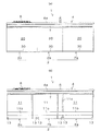
以下、実施の形態について図面を参照して説明する。図1〜図3は、台所K側とダイニングルームD側とを区画するように配設された対面型のシステムキッチン1を示している。このシステムキッチン1は、同図に示すように、上面開口部を有する複数のキャビネットユニット2a、2b、2cからなるベースキャビネット2と、このベースキャビネット2の上面開口部に固定設置される、シンク5を有するカウンター4とを備えており、カウンター4には、ガスコンロ6等の器具が装着されると共に、中央に配置されるキャビネットユニット2bには食洗機3が組み込まれている。
Hereinafter, embodiments will be described with reference to the drawings. 1 to 3 show a face-to-
前記キャビネットユニット2a、2b、2cは、背板11の外面側の所定位置に上部横桟木11a及び下部横桟木11bがそれぞれ固定されており、それぞれの上部横桟木11aにベースキャビネット2の全幅と略同一長さの長尺の上部支持材12を固定することによって、キャビネットユニット2a、2b、2cが相互に連結されている。
In the
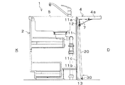
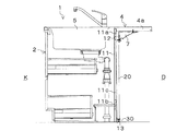
前記カウンター4は、図3(a)、(b)に示すように、ベースキャビネット2の背板11からダイニングルームD側に張り出しており、その張出部4aは、上部支持材12に、その上部支持材12と略同一長さのカウンター固定金具7を介して支持されていると共に、上部支持材12の下方側には、キャビネットユニット2a、2b、2cの背板11を覆うように、3枚の装飾パネル20が着脱自在に取り付けられている。なお、シンク側のキャビネットユニット2aには、図2(a)、(b)に示すように、中央の装飾パネル20とシンク側の装飾パネル20の境界部分に双方の装飾パネルの側端部を支持するための縦桟木11cが背板11に取り付けられている。
As shown in FIGS. 3 (a) and 3 (b), the
前記カウンター固定金具7の下端部は、上部支持材12の下端面よりも10mm程度下方側に張り出しており、図3(a)に示すように、載置部材30に載置した装飾パネル20の上端部を、上部支持材12の下端面から張り出したカウンター固定金具7の下端部に係止させることで、装飾パネル20が背板11の外面に沿うように支持されている。
The lower end portion of the
前記装飾パネル20は、図4(a)〜(c)に示すように、厚さ5.5mmの合板によって長方形状に形成された枠材22、この枠材22の内側に収容された、中空ポリエステル繊維とバージンウールとを立体的に編み込んだ吸音材(登録商標「サーモウール」 (株)コスモプロジェクト製)23、この吸音材23の一方の外表面の中央部に配設された、活性炭シートと光触媒シートとをラミネートした複合シート24からなる心板21と、この心板21における複合シート24が配設されたほうの外表面及び端面を被覆する布地25とから構成されており、複合シート24は、光触媒シートが布地25側を向くように配置されている。
As shown in FIGS. 4A to 4C, the
前記載置部材30は、図5(a)〜(d)、図6及び図7(a)、(b)に示すように、装飾パネル20の全幅と略同一長さのアルミニウム成形品であり、装飾パネル20を立てた状態で載置する載置面30aを有する本体部31と、この本体部31の載置面30aの前端縁から立ち上がる操作部32と、本体部31における後面の両端部に取り付けられた一対のマグネットユニット33とを備えており、マグネットユニット33のマグネットが、背板11の外面側の所定位置で床面にねじ止めされた磁性体からなる縦断面L字状の保持金具13に吸着されることで、装飾パネル20を載置した載置部材30が前後方向に位置決めされ、容易に位置ずれしないようになっている。
As shown in FIGS. 5A to 5D, FIGS. 6 and 7A and 7B, the
前記本体部31は、前面板、後面板、上面板及び下面板によって角筒状に形成されており、上面板が後面板よりも後方側に張り出すことによって、装飾パネル20の厚みと略同一幅の載置面30aが形成されていると共に、操作部32は、操作しやすいように、上端部が前方側に僅かに張り出すことによって肉厚に形成されている。
The
また、本体部31は、前面板の下端部が前方側に僅かに突出した突条31aを有しており、操作部32を操作することによって、この突条31aを支点として、載置部材30を前方側に回転させることができるようになっている。
The
以下、装飾パネル20の着脱方法について説明する。まず、装飾パネル20を取り付けるには、図8及び図9に示すように、背板11の前方側(ダイニングルームD側)において、装飾パネル20を載置部材30の載置面30aに載置した状態で、装飾パネル20を傾けて、その上端部を背板11の外面に当接させた後、図10に示すように、載置部材30を背板11側にスライドさせていき、マグネットユニット33のマグネットを保持金具13に吸着させると、図11に示すように、装飾パネル20の上端部が背板11とカウンター固定金具7の下端部との間に挟み込まれ、装飾パネル20が背板11の外面に沿うように支持される。
Hereinafter, a method for attaching and detaching the
このようにして取り付けられた装飾パネル20を取り外すには、図12及び図13に示すように、装飾パネル20が載置されている載置部材30の操作部32を操作して、載置部材30を本体部31の下端部の突条31aを支点として背板11の前方側(図13に円弧矢印で示す方向)に回転させることによって、装飾パネル20を一旦持ち上げながら、載置部材30を装飾パネル20の下方位置から前方側に待避させると、図14及び図15に示すように、装飾パネル20が載置部材30から外れて床面上に落下して、装飾パネル20の上端位置がカウンター固定金具7の下端部よりも下方側に移動し、カウンター固定金具7の下端部による装飾パネル20の支持が解除されるので、装飾パネル20の上端部を手前に引き出すようにして取り外せばよい。
In order to remove the
以上のように、このシステムキッチン1のベースキャビネット2は、枠材22の内側に吸音材23を配設してなる心板21の少なくとも外表面及び端面が布地によって覆われた装飾パネル20を、背板11の外面側に取り付けてあるので、台所Kでの調理作業によって発生する音や、ベースキャビネット2内に組み込まれている食洗機3からの食器洗浄音が装飾パネル20の吸音材23に吸音されることによって、ダイニングルームD側に伝搬されにくく、ダイニングルームDにおいて、食事をしたり、テレビを見たり、音楽を鑑賞したり、読書をしたりする際に、台所側の騒音が気にならないという効果が得られる。
As described above, the
また、装飾パネル20は、ダイニングルームD側に露出する外表面が布地25によって形成されているので、柔らかい印象を与えると共に、ダイニングルームDの雰囲気にあった統一感を与えることも可能となり、デザイン面においても優れている。
Moreover, since the outer surface exposed to the dining room D side is formed by the
また、装飾パネル20の心板21が、吸音材23の外面側に配設された活性炭シートと光触媒シートとをラミネートした複合シート24を備えているので、不快に感じるペット、たばこ、排水・生ゴミ等に起因した生活臭や、シックハウス症候群の原因物質であるホルムアルデヒド等の揮発性有機化合物(VOC)を活性炭シートが吸着すると共に、装飾パネル20の布地25を透過してくる光を光触媒シートが吸収することによって、シート表面に酸化還元力が発生し、この酸化還元力によって、生活臭の発生原因となっている物質や、ホルムアルデヒド等の揮発性有機化合物(VOC)が分解除去され、さらに、抗菌効果を得ることもできるので、ダイニングルームDの環境改善を図ることができる。
Further, since the
また、装飾パネル20を構成している、中空ポリエステル繊維とバージンウールとを立体的に編み込んだ吸音材23は、室内の湿度を50%前後に保とうとする調湿機能を備えており、湿度が高いときは吸湿し、湿度が低いときは放湿するので、ダイニングルームD内を快適な空間に保つことができるという効果もある。
In addition, the
なお、上述したベースキャビネット2では、背板11の外面側だけに装飾パネル20を取り付けているが、さらに、露出している一方の側板の外面側にも装飾パネル20を着脱自在に取り付けるようにしてもよい。その場合は、ベースキャビネットの側板にマグネットまたは磁性体からなる保持金具を取り付けると共に、装飾パネルにおけるベースキャビネット側のマグネットまたは保持金具に対応する位置に、磁性体からなる保持金具またはマグネットを取り付けておき、両者を磁気によって吸着させるようにすればよい。
In the
また、上述したベースキャビネット2では、活性炭シートと光触媒シートとをラミネートした複合シート24を備えた装飾パネル20を使用しているが、これに限定されるものではなく、活性炭シートや光触媒シートのいずれか一方だけを備えた装飾パネルや、活性炭シート、光触媒シート単体や複合シート24を省略した装飾パネルを使用することもできる。
Moreover, in the
また、上述したベースキャビネット2では、装飾パネル20の心板を構成している吸音材として、中空ポリエステル繊維とバージンウールとを立体的に編み込んだ吸音材を使用しているが、これに限定されるものではなく、種々の吸音材を使用することができる。
Moreover, in the
また、上述した実施形態では、ユーザが工具を使用せずに装飾パネル20の着脱を行うことができるように、カウンター固定金具7と載置部材30とを利用して、背板11の外面側に装飾パネル20を取り付けるようにしているが、これに限定されるものではなく、装飾パネル20を背板にねじ止めする等の種々の取付方法を採用することができることはいうまでもない。
Moreover, in embodiment mentioned above, the outer surface side of the
本発明は、対面型のシステムキッチン用のベースキャビネットに利用することができる。 The present invention can be used for a base cabinet for a face-to-face system kitchen.
1 システムキッチン
2 ベースキャビネット
2a、2b、2c キャビネットユニット
3 食洗機
4 カウンター
4a 張出部
5 シンク
6 ガスコンロ
7 カウンター固定金具
11 背板
11a 上部横桟木
11b 下部横桟木
11c 縦桟木
12 上部支持材
13 保持金具
20 装飾パネル
21 心板
22 枠材
23 吸音材
24 複合シート
25 布地
30 載置部材
30a 載置面
31 本体部
31a 突条
32 操作部
33 マグネットユニット
D ダイニングルーム
K 台所
DESCRIPTION OF
Claims (4)
前記背板の外面側に装飾パネルが取り付けられており、
前記装飾パネルは、所定厚みを有する平板状の吸音材及び前記吸音材の端面を覆うように、前記吸音材を全周に渡って取り囲む枠材を有する心板と、前記心板の外表面及び端面を直接覆う布地とを備えており、
前記枠材は、前記心板の外面側及び内面側の双方が開放されていることを特徴とするシステムキッチン用のベースキャビネット。 A base cabinet for a face-to-face system kitchen disposed between the dining or living dining room and the kitchen so that the back plate faces the dining side or the living dining side,
A decorative panel is attached to the outer surface side of the back plate,
The decorative panel has a flat plate-like sound absorbing material having a predetermined thickness and a core plate that surrounds the sound absorbing material over the entire circumference so as to cover an end surface of the sound absorbing material, an outer surface of the core plate , And fabric that directly covers the end face,
The frame material is a base cabinet for a system kitchen, wherein both the outer surface side and the inner surface side of the core plate are open.
Priority Applications (1)
| Application Number | Priority Date | Filing Date | Title |
|---|---|---|---|
| JP2013021153A JP5870050B2 (en) | 2013-02-06 | 2013-02-06 | System kitchen base cabinet |
Applications Claiming Priority (1)
| Application Number | Priority Date | Filing Date | Title |
|---|---|---|---|
| JP2013021153A JP5870050B2 (en) | 2013-02-06 | 2013-02-06 | System kitchen base cabinet |
Related Child Applications (1)
| Application Number | Title | Priority Date | Filing Date |
|---|---|---|---|
| JP2015158701A Division JP6211567B2 (en) | 2015-08-11 | 2015-08-11 | System kitchen base cabinet |
Publications (3)
| Publication Number | Publication Date |
|---|---|
| JP2014150862A JP2014150862A (en) | 2014-08-25 |
| JP2014150862A5 JP2014150862A5 (en) | 2015-07-02 |
| JP5870050B2 true JP5870050B2 (en) | 2016-02-24 |
Family
ID=51573371
Family Applications (1)
| Application Number | Title | Priority Date | Filing Date |
|---|---|---|---|
| JP2013021153A Active JP5870050B2 (en) | 2013-02-06 | 2013-02-06 | System kitchen base cabinet |
Country Status (1)
| Country | Link |
|---|---|
| JP (1) | JP5870050B2 (en) |
Cited By (1)
| Publication number | Priority date | Publication date | Assignee | Title |
|---|---|---|---|---|
| JP7141373B2 (en) | 2019-08-26 | 2022-09-22 | 東芝三菱電機産業システム株式会社 | Stator torque transmission structure, electric motor drive system, assembly/disassembly method for stator torque transmission structure, and disassembly jig for stator torque transmission structure |
Family Cites Families (5)
| Publication number | Priority date | Publication date | Assignee | Title |
|---|---|---|---|---|
| JPS611522U (en) * | 1984-06-12 | 1986-01-08 | 秀朗 宮内 | panel board |
| JPH059755Y2 (en) * | 1986-01-21 | 1993-03-10 | ||
| JP2505271Y2 (en) * | 1990-05-19 | 1996-07-24 | 共栄工業株式会社 | Panel covering material installation device |
| JP2003227203A (en) * | 2002-01-31 | 2003-08-15 | Kokuyo Co Ltd | Panel |
| JP3109580U (en) * | 2004-12-27 | 2005-05-19 | 株式会社トーシン | Panel, indoor building material and furniture using the panel |
-
2013
- 2013-02-06 JP JP2013021153A patent/JP5870050B2/en active Active
Cited By (1)
| Publication number | Priority date | Publication date | Assignee | Title |
|---|---|---|---|---|
| JP7141373B2 (en) | 2019-08-26 | 2022-09-22 | 東芝三菱電機産業システム株式会社 | Stator torque transmission structure, electric motor drive system, assembly/disassembly method for stator torque transmission structure, and disassembly jig for stator torque transmission structure |
Also Published As
| Publication number | Publication date |
|---|---|
| JP2014150862A (en) | 2014-08-25 |
Similar Documents
| Publication | Publication Date | Title |
|---|---|---|
| USD778007S1 (en) | Dishwasher control panel | |
| USD745751S1 (en) | Dishwasher door control panel | |
| USD743122S1 (en) | Lighted dishwasher door | |
| USD730592S1 (en) | Dishwasher control panel | |
| USD741034S1 (en) | Control panel for a dishwasher door | |
| USD637897S1 (en) | Mounting bracket useful for ceiling grid systems | |
| USD741032S1 (en) | Dishwasher control panel | |
| JP5870050B2 (en) | System kitchen base cabinet | |
| JP5029489B2 (en) | Built-in induction heating cooker | |
| JP6211567B2 (en) | System kitchen base cabinet | |
| USD564020S1 (en) | Menu holder | |
| JP4812564B2 (en) | Cooker | |
| JP3154900U (en) | Pet toilet | |
| JP2015104562A (en) | Kitchen contrivance | |
| WO2019020038A1 (en) | Stain-resistant soundproof closed personal compartment suitable for high-intensity use | |
| JP4939992B2 (en) | Kitchen unit | |
| JP2009005877A (en) | Modular kitchen | |
| JP2007078296A (en) | Heating cooker | |
| KR101301944B1 (en) | Charcoal built-in desk | |
| JP2008215629A (en) | Range hood | |
| JP2008237505A (en) | Kitchen unit | |
| JP2010071571A5 (en) | ||
| CN201641051U (en) | Audiovisual kitchen cabinet | |
| JP2008036055A (en) | Integrated kitchen system with movable heat-cooker | |
| JP2010094380A (en) | Kitchen unit |
Legal Events
| Date | Code | Title | Description |
|---|---|---|---|
| A521 | Written amendment |
Free format text: JAPANESE INTERMEDIATE CODE: A523 Effective date: 20150513 |
|
| A621 | Written request for application examination |
Free format text: JAPANESE INTERMEDIATE CODE: A621 Effective date: 20150513 |
|
| A871 | Explanation of circumstances concerning accelerated examination |
Free format text: JAPANESE INTERMEDIATE CODE: A871 Effective date: 20150513 |
|
| A975 | Report on accelerated examination |
Free format text: JAPANESE INTERMEDIATE CODE: A971005 Effective date: 20150615 |
|
| A131 | Notification of reasons for refusal |
Free format text: JAPANESE INTERMEDIATE CODE: A131 Effective date: 20150624 |
|
| A521 | Written amendment |
Free format text: JAPANESE INTERMEDIATE CODE: A523 Effective date: 20150811 |
|
| A131 | Notification of reasons for refusal |
Free format text: JAPANESE INTERMEDIATE CODE: A131 Effective date: 20150902 |
|
| A521 | Written amendment |
Free format text: JAPANESE INTERMEDIATE CODE: A523 Effective date: 20151023 |
|
| TRDD | Decision of grant or rejection written | ||
| A01 | Written decision to grant a patent or to grant a registration (utility model) |
Free format text: JAPANESE INTERMEDIATE CODE: A01 Effective date: 20160105 |
|
| A61 | First payment of annual fees (during grant procedure) |
Free format text: JAPANESE INTERMEDIATE CODE: A61 Effective date: 20160108 |
|
| R150 | Certificate of patent or registration of utility model |
Ref document number: 5870050 Country of ref document: JP Free format text: JAPANESE INTERMEDIATE CODE: R150 |