JP5868408B2 - Method for correlating a monitoring device to the end of life of a filter cartridge - Google Patents
Method for correlating a monitoring device to the end of life of a filter cartridge Download PDFInfo
- Publication number
- JP5868408B2 JP5868408B2 JP2013531602A JP2013531602A JP5868408B2 JP 5868408 B2 JP5868408 B2 JP 5868408B2 JP 2013531602 A JP2013531602 A JP 2013531602A JP 2013531602 A JP2013531602 A JP 2013531602A JP 5868408 B2 JP5868408 B2 JP 5868408B2
- Authority
- JP
- Japan
- Prior art keywords
- filter cartridge
- monitoring device
- monitor
- cartridge
- detection
- Prior art date
- Legal status (The legal status is an assumption and is not a legal conclusion. Google has not performed a legal analysis and makes no representation as to the accuracy of the status listed.)
- Expired - Fee Related
Links
Images


Classifications
-
- A—HUMAN NECESSITIES
- A62—LIFE-SAVING; FIRE-FIGHTING
- A62B—DEVICES, APPARATUS OR METHODS FOR LIFE-SAVING
- A62B18/00—Breathing masks or helmets, e.g. affording protection against chemical agents or for use at high altitudes or incorporating a pump or compressor for reducing the inhalation effort
- A62B18/08—Component parts for gas-masks or gas-helmets, e.g. windows, straps, speech transmitters, signal-devices
- A62B18/088—Devices for indicating filter saturation
-
- G—PHYSICS
- G01—MEASURING; TESTING
- G01N—INVESTIGATING OR ANALYSING MATERIALS BY DETERMINING THEIR CHEMICAL OR PHYSICAL PROPERTIES
- G01N21/00—Investigating or analysing materials by the use of optical means, i.e. using sub-millimetre waves, infrared, visible or ultraviolet light
- G01N21/17—Systems in which incident light is modified in accordance with the properties of the material investigated
- G01N21/25—Colour; Spectral properties, i.e. comparison of effect of material on the light at two or more different wavelengths or wavelength bands
-
- G—PHYSICS
- G01—MEASURING; TESTING
- G01D—MEASURING NOT SPECIALLY ADAPTED FOR A SPECIFIC VARIABLE; ARRANGEMENTS FOR MEASURING TWO OR MORE VARIABLES NOT COVERED IN A SINGLE OTHER SUBCLASS; TARIFF METERING APPARATUS; MEASURING OR TESTING NOT OTHERWISE PROVIDED FOR
- G01D18/00—Testing or calibrating apparatus or arrangements provided for in groups G01D1/00 - G01D15/00
-
- B—PERFORMING OPERATIONS; TRANSPORTING
- B01—PHYSICAL OR CHEMICAL PROCESSES OR APPARATUS IN GENERAL
- B01D—SEPARATION
- B01D53/00—Separation of gases or vapours; Recovering vapours of volatile solvents from gases; Chemical or biological purification of waste gases, e.g. engine exhaust gases, smoke, fumes, flue gases, aerosols
- B01D53/02—Separation of gases or vapours; Recovering vapours of volatile solvents from gases; Chemical or biological purification of waste gases, e.g. engine exhaust gases, smoke, fumes, flue gases, aerosols by adsorption, e.g. preparative gas chromatography
- B01D53/04—Separation of gases or vapours; Recovering vapours of volatile solvents from gases; Chemical or biological purification of waste gases, e.g. engine exhaust gases, smoke, fumes, flue gases, aerosols by adsorption, e.g. preparative gas chromatography with stationary adsorbents
- B01D53/0454—Controlling adsorption
-
- B—PERFORMING OPERATIONS; TRANSPORTING
- B01—PHYSICAL OR CHEMICAL PROCESSES OR APPARATUS IN GENERAL
- B01D—SEPARATION
- B01D53/00—Separation of gases or vapours; Recovering vapours of volatile solvents from gases; Chemical or biological purification of waste gases, e.g. engine exhaust gases, smoke, fumes, flue gases, aerosols
- B01D53/14—Separation of gases or vapours; Recovering vapours of volatile solvents from gases; Chemical or biological purification of waste gases, e.g. engine exhaust gases, smoke, fumes, flue gases, aerosols by absorption
-
- G—PHYSICS
- G01—MEASURING; TESTING
- G01F—MEASURING VOLUME, VOLUME FLOW, MASS FLOW OR LIQUID LEVEL; METERING BY VOLUME
- G01F25/00—Testing or calibration of apparatus for measuring volume, volume flow or liquid level or for metering by volume
-
- G—PHYSICS
- G01—MEASURING; TESTING
- G01N—INVESTIGATING OR ANALYSING MATERIALS BY DETERMINING THEIR CHEMICAL OR PHYSICAL PROPERTIES
- G01N21/00—Investigating or analysing materials by the use of optical means, i.e. using sub-millimetre waves, infrared, visible or ultraviolet light
- G01N21/17—Systems in which incident light is modified in accordance with the properties of the material investigated
- G01N21/25—Colour; Spectral properties, i.e. comparison of effect of material on the light at two or more different wavelengths or wavelength bands
- G01N21/29—Colour; Spectral properties, i.e. comparison of effect of material on the light at two or more different wavelengths or wavelength bands using visual detection
-
- G—PHYSICS
- G01—MEASURING; TESTING
- G01N—INVESTIGATING OR ANALYSING MATERIALS BY DETERMINING THEIR CHEMICAL OR PHYSICAL PROPERTIES
- G01N33/00—Investigating or analysing materials by specific methods not covered by groups G01N1/00 - G01N31/00
- G01N33/0004—Gaseous mixtures, e.g. polluted air
- G01N33/0009—General constructional details of gas analysers, e.g. portable test equipment
- G01N33/007—Arrangements to check the analyser
-
- B—PERFORMING OPERATIONS; TRANSPORTING
- B01—PHYSICAL OR CHEMICAL PROCESSES OR APPARATUS IN GENERAL
- B01D—SEPARATION
- B01D2253/00—Adsorbents used in seperation treatment of gases and vapours
- B01D2253/10—Inorganic adsorbents
- B01D2253/102—Carbon
-
- B—PERFORMING OPERATIONS; TRANSPORTING
- B01—PHYSICAL OR CHEMICAL PROCESSES OR APPARATUS IN GENERAL
- B01D—SEPARATION
- B01D2253/00—Adsorbents used in seperation treatment of gases and vapours
- B01D2253/10—Inorganic adsorbents
- B01D2253/104—Alumina
-
- B—PERFORMING OPERATIONS; TRANSPORTING
- B01—PHYSICAL OR CHEMICAL PROCESSES OR APPARATUS IN GENERAL
- B01D—SEPARATION
- B01D2253/00—Adsorbents used in seperation treatment of gases and vapours
- B01D2253/10—Inorganic adsorbents
- B01D2253/106—Silica or silicates
-
- B—PERFORMING OPERATIONS; TRANSPORTING
- B01—PHYSICAL OR CHEMICAL PROCESSES OR APPARATUS IN GENERAL
- B01D—SEPARATION
- B01D2253/00—Adsorbents used in seperation treatment of gases and vapours
- B01D2253/10—Inorganic adsorbents
- B01D2253/112—Metals or metal compounds not provided for in B01D2253/104 or B01D2253/106
- B01D2253/1124—Metal oxides
-
- B—PERFORMING OPERATIONS; TRANSPORTING
- B01—PHYSICAL OR CHEMICAL PROCESSES OR APPARATUS IN GENERAL
- B01D—SEPARATION
- B01D2253/00—Adsorbents used in seperation treatment of gases and vapours
- B01D2253/10—Inorganic adsorbents
- B01D2253/116—Molecular sieves other than zeolites
-
- B—PERFORMING OPERATIONS; TRANSPORTING
- B01—PHYSICAL OR CHEMICAL PROCESSES OR APPARATUS IN GENERAL
- B01D—SEPARATION
- B01D2253/00—Adsorbents used in seperation treatment of gases and vapours
- B01D2253/20—Organic adsorbents
- B01D2253/204—Metal organic frameworks (MOF's)
-
- B—PERFORMING OPERATIONS; TRANSPORTING
- B01—PHYSICAL OR CHEMICAL PROCESSES OR APPARATUS IN GENERAL
- B01D—SEPARATION
- B01D2257/00—Components to be removed
- B01D2257/70—Organic compounds not provided for in groups B01D2257/00 - B01D2257/602
- B01D2257/702—Hydrocarbons
- B01D2257/7022—Aliphatic hydrocarbons
-
- B—PERFORMING OPERATIONS; TRANSPORTING
- B01—PHYSICAL OR CHEMICAL PROCESSES OR APPARATUS IN GENERAL
- B01D—SEPARATION
- B01D2257/00—Components to be removed
- B01D2257/70—Organic compounds not provided for in groups B01D2257/00 - B01D2257/602
- B01D2257/702—Hydrocarbons
- B01D2257/7027—Aromatic hydrocarbons
-
- B—PERFORMING OPERATIONS; TRANSPORTING
- B01—PHYSICAL OR CHEMICAL PROCESSES OR APPARATUS IN GENERAL
- B01D—SEPARATION
- B01D2257/00—Components to be removed
- B01D2257/70—Organic compounds not provided for in groups B01D2257/00 - B01D2257/602
- B01D2257/708—Volatile organic compounds V.O.C.'s
-
- B—PERFORMING OPERATIONS; TRANSPORTING
- B01—PHYSICAL OR CHEMICAL PROCESSES OR APPARATUS IN GENERAL
- B01D—SEPARATION
- B01D2258/00—Sources of waste gases
- B01D2258/06—Polluted air
-
- B—PERFORMING OPERATIONS; TRANSPORTING
- B01—PHYSICAL OR CHEMICAL PROCESSES OR APPARATUS IN GENERAL
- B01D—SEPARATION
- B01D2259/00—Type of treatment
- B01D2259/45—Gas separation or purification devices adapted for specific applications
- B01D2259/4541—Gas separation or purification devices adapted for specific applications for portable use, e.g. gas masks
-
- B—PERFORMING OPERATIONS; TRANSPORTING
- B01—PHYSICAL OR CHEMICAL PROCESSES OR APPARATUS IN GENERAL
- B01D—SEPARATION
- B01D53/00—Separation of gases or vapours; Recovering vapours of volatile solvents from gases; Chemical or biological purification of waste gases, e.g. engine exhaust gases, smoke, fumes, flue gases, aerosols
- B01D53/34—Chemical or biological purification of waste gases
- B01D53/46—Removing components of defined structure
- B01D53/72—Organic compounds not provided for in groups B01D53/48 - B01D53/70, e.g. hydrocarbons
-
- G—PHYSICS
- G01—MEASURING; TESTING
- G01N—INVESTIGATING OR ANALYSING MATERIALS BY DETERMINING THEIR CHEMICAL OR PHYSICAL PROPERTIES
- G01N21/00—Investigating or analysing materials by the use of optical means, i.e. using sub-millimetre waves, infrared, visible or ultraviolet light
- G01N21/75—Systems in which material is subjected to a chemical reaction, the progress or the result of the reaction being investigated
- G01N21/77—Systems in which material is subjected to a chemical reaction, the progress or the result of the reaction being investigated by observing the effect on a chemical indicator
- G01N21/78—Systems in which material is subjected to a chemical reaction, the progress or the result of the reaction being investigated by observing the effect on a chemical indicator producing a change of colour
- G01N21/783—Systems in which material is subjected to a chemical reaction, the progress or the result of the reaction being investigated by observing the effect on a chemical indicator producing a change of colour for analysing gases
Description
本開示は、空気清浄化の有用な耐用期間の終点を表示するためにモニターを使用する方法に関する。 The present disclosure relates to a method of using a monitor to indicate the end of useful useful life of air purification.
有害な空気汚染物質から人々を保護するために様々な空気清浄機が開発されてきた。これらの空気清浄機には、空気中に存在する汚染物質を濾別又は収着するように設計された広範な空気清浄化レスピレーターがある。典型的には、これらの空気清浄化レスピレーターは、フィルター媒体、フィルター体、又はフィルター媒体及びフィルター体の一部の組み合わせを含む。レスピレーターの使用時、汚染物質は、フィルター体により吸収されるか、又は付着又は捕捉されるかたちになる。最終的に、フィルター媒体又はフィルター体は飽和し、レスピレーターの有害な空気汚染物質の除去能力は減少し始める。 Various air purifiers have been developed to protect people from harmful air pollutants. These air purifiers have a wide range of air purifying respirators designed to filter or sorb contaminants present in the air. Typically, these air cleaning respirators include filter media, filter bodies, or some combination of filter media and filter bodies. During use of the respirator, contaminants are either absorbed by the filter body or become attached or trapped. Eventually, the filter media or filter body saturates and the respirator's ability to remove harmful air pollutants begins to decrease.
有害な空気汚染物質を含有する環境への長期の暴露、例えば、このような環境への連続的又は反復的な作業者暴露時には、レスピレーターの有用な耐用期間を決めるための方法が必要である。開発された1つの方法は、レスピレーターに対する使用時間に基づくものである。この方法においては、レスピレーター又は空気清浄化フィルターは、しかるべき使用期間の後取り換えられる。しかしながら、この方法は、レスピレーターを通った汚染物質の量又は流量の変動を考慮に入れず、それゆえレスピレーター又はフィルター要素の交換が早すぎる(無駄である)又は遅すぎる(使用者に危険をもたらすことがある)という結果を生じる可能性がある。 During long-term exposure to environments containing harmful air pollutants, such as continuous or repeated worker exposure to such environments, a method is needed to determine the useful life of the respirator. One method that has been developed is based on usage time for the respirator. In this method, the respirator or air purification filter is replaced after an appropriate period of use. However, this method does not take into account variations in the amount or flow rate of contaminants through the respirator, and therefore replacement of the respirator or filter element is too early (wasted) or too late (has a danger to the user) May result).
モニター装置をフィルターカートリッジの耐用期間に相関付けるための方法が本明細書で開示される。これらの方法はモニター装置を準備し、このモニター装置を較正して、フィルターカートリッジの耐用期間に対応させることを含む。このモニター装置は、容器内のデマンド物質、検出点を持つ検出要素、検出要素用のリーダー、及び流体送達装置を含む。この流体送達装置は、流体送達パラメーターを含み、この流体送達パラメーターおよびこの検出要素の検出点がフィルターカートリッジの耐用期間に相関付けられる。 Disclosed herein is a method for correlating a monitoring device with the life of a filter cartridge. These methods include providing a monitoring device and calibrating the monitoring device to accommodate the life of the filter cartridge. The monitoring device includes a demand material in the container, a detection element having a detection point, a reader for the detection element, and a fluid delivery device. The fluid delivery device includes a fluid delivery parameter, and the fluid delivery parameter and the detection point of the sensing element are correlated to the lifetime of the filter cartridge.
このモニター装置を較正して、このフィルターカートリッジの耐用期間に対応させることは、このフィルターカートリッジに対する滞留時間を決定すること、このモニター装置に対する滞留時間を決定すること、このモニター装置の滞留時間のこのフィルターカートリッジの滞留時間に対する比を決定すること、及びこの比を使用して、このモニター装置内のセンサーの応答をフィルターカートリッジの耐用期間に相関付けることを含む。このモニター装置内のセンサーの応答は、この流体送達装置の流体送達パラメーターの制御によりこのフィルターカートリッジの耐用期間に相関付けられる。この流体送達パラメーターは、このモニター装置の流量、デマンド物質重量、容器断面積、容器容積、容器長さ、及びデマンド物質充填密度を最低限に含む。 Calibrating the monitor device to accommodate the life of the filter cartridge determines the dwell time for the filter cartridge, determines the dwell time for the monitor device, the dwell time for the monitor device Determining the ratio of the filter cartridge to the residence time and using this ratio to correlate the response of the sensor in the monitoring device to the life of the filter cartridge. The response of the sensor in the monitoring device is correlated to the lifetime of the filter cartridge by controlling the fluid delivery parameters of the fluid delivery device. The fluid delivery parameters minimally include the flow rate, demand material weight, container cross-sectional area, container volume, container length, and demand substance fill density of the monitoring device.
添付図面と共に以下の本開示の様々な実施形態の詳細な説明を検討することで、本開示をより完全に理解することができる。
空気清浄化レスピレーターなどの空気清浄機の有用な耐用期間の終点をモニター及び検出するための方法、及び装置に対する必要性が存在する。ときには耐用期間の終点インジケータ又はESLIと呼ばれる、このような装置は、様々な環境で使用するのに充分堅牢で、かつこの装置の使用者と共に場所から場所に移動できるように充分に可搬型でなければならず、空気清浄化の有用な耐用期間の終点を相関付けるための方法を利用しなければならない。 There is a need for a method and apparatus for monitoring and detecting the useful life end of an air purifier, such as an air purifying respirator. Such devices, sometimes referred to as end-of-life indicators or ESLI, must be sufficiently robust to be used in various environments and portable enough to be moved from location to location with the user of the device. And a method for correlating the end points of the useful life of the air purification must be utilized.
空気清浄化システムの有用な耐用期間の終点をモニター及び検出するための可搬型装置が本明細書で開示される方法で使用される。これらの可搬型装置は、有機蒸気への暴露に対して防御するように設計されたレスピレーターの有用な耐用期間の終点のモニター及び検出に特に好適である。本明細書で使用される用語「有機蒸気」は、呼吸する空気中に存在する場合、人々に有害であり得る広範な揮発性の空中浮遊有機化合物を指す。有機蒸気の例には、イソプロパノール及びブタノールなどのアルコール;ヘキサン及びオクタンなどのアルカン;ベンゼン、トルエン、キシレン、及びスチレンなどの芳香族;クロロホルム及びメチレンクロリドなどのハロカーボン;アセトン及びメチルエチルケトンなどのケトン;テトラヒドロフランなどのエーテル;エチルアセテート及びエトキシエチルアセテートなどのエステル;メチルアクリレートなどのアクリレート;アセトニトリルなどのニトリル;トルエン−2,4−ジイソシアネートなどのイソシアネート等が挙げられるが、これらに限定されない。典型的には、有機蒸気レスピレーターは、有機蒸気を捕捉及び保持する吸収性媒体を含む。 A portable device for monitoring and detecting the useful life end of an air cleaning system is used in the methods disclosed herein. These portable devices are particularly suitable for monitoring and detecting the end of useful useful life of respirators designed to protect against exposure to organic vapors. The term “organic vapor” as used herein refers to a wide range of volatile airborne organic compounds that can be harmful to people when present in the breathing air. Examples of organic vapors include alcohols such as isopropanol and butanol; alkanes such as hexane and octane; aromatics such as benzene, toluene, xylene, and styrene; halocarbons such as chloroform and methylene chloride; ketones such as acetone and methyl ethyl ketone; Examples include, but are not limited to, ethers such as tetrahydrofuran; esters such as ethyl acetate and ethoxyethyl acetate; acrylates such as methyl acrylate; nitriles such as acetonitrile; isocyanates such as toluene-2,4-diisocyanate. Typically, an organic vapor respirator includes an absorbent medium that traps and retains organic vapor.
モニター装置をフィルターカートリッジの有用な耐用期間に相関付ける方法は、モニター装置を準備し、及びモニター装置の耐用期間を較正して、フィルターカートリッジの耐用期間に対応させることを含む。好適なモニター装置を以下に述べる。モニター装置はフィルターカートリッジを模倣しているが、フィルターカートリッジの有用な耐用期間が終わる時点を決定するためにモニター可能である。モニター装置をモニターし、及びモニター装置のセンサー応答をフィルターカートリッジの耐用期間の終点に相関付けることにより、使用者は、フィルターカートリッジの有用な耐用期間を決定することができる。 A method of correlating the monitoring device with the useful life of the filter cartridge includes providing the monitoring device and calibrating the life of the monitoring device to accommodate the life of the filter cartridge. A suitable monitoring device is described below. The monitoring device mimics the filter cartridge, but can be monitored to determine when the useful life of the filter cartridge ends. By monitoring the monitoring device and correlating the sensor response of the monitoring device to the end of life of the filter cartridge, the user can determine the useful life of the filter cartridge.
モニター装置のフィルターカートリッジの耐用期間の終点への相関付けは、モニター装置をフィルターカートリッジの耐用期間の終点に対して較正することにより決定される。この較正は、H.J.Cohen及び共同研究者による以前の研究、ジャーナルリファレンスAm.Ind.Assoc.J.;486〜495(1989)において使用された方法、レスピレーター活性炭管、すなわちRCTを使用して、レスピレーターカートリッジに対する耐用期間を予測する方法に類似している。このような装置は、RCTの出力流れ中の有機蒸気の存在を測定するためにベンチトップ規模の赤外分光計などの大きな装置を必要とする。Cohen及び共同研究者により記述された装置は、本発明のハンドヘルド装置での使用には不適であるが、較正方法は類似している。 The correlation of the monitoring device's filter cartridge end-of-life is determined by calibrating the monitoring device to the end-of-life of the filter cartridge. This calibration is the same as that of H.C. J. et al. Previous work by Cohen and collaborators, Journal Reference Am. Ind. Assoc. J. et al. 486-495 (1989), similar to the method used to predict the service life for a respirator cartridge using a respirator activated carbon tube, or RCT. Such a device requires a large device such as a bench top scale infrared spectrometer to measure the presence of organic vapor in the RCT output stream. Although the device described by Cohen and co-workers is unsuitable for use with the handheld device of the present invention, the calibration method is similar.
この較正は、フィルターカートリッジの滞留時間、モニター装置の滞留時間及びフィルターカートリッジの滞留時間及びモニター装置の滞留時間の比を求めることにより行われる。用語「滞留時間」は、本明細書で使用されるとき、濾過媒体を横断する空気の分子又は塊が媒体を完全に横断する時間を指す。滞留時間は、様々な流体送達パラメーターを制御することにより制御可能である。これらの流体送達パラメーターの一部は、フィルター媒体を収めた容器の大きさを制御するより確立される。これらのパラメーターには、容器の断面積、容器容積、及び容器長さが挙げられる。他のこれらの流体送達パラメーターは、フィルター媒体及びフィルター媒体を容器中に配置する方法の選択により制御される。これらのパラメーターにはフィルター媒体の重量及びフィルター媒体の充填密度が挙げられる。流量などの更に他の流体パラメーターは、装置の使用者により制御される。レスピレーターカートリッジ内の滞留時間は、主として使用者の呼吸速度により決定される。 This calibration is performed by determining the ratio of the residence time of the filter cartridge, the residence time of the monitoring device and the residence time of the filter cartridge and the residence time of the monitoring device. The term “residence time” as used herein refers to the time for air molecules or masses traversing the filtration media to completely traverse the media. Residence time can be controlled by controlling various fluid delivery parameters. Some of these fluid delivery parameters are established by controlling the size of the container containing the filter media. These parameters include container cross-sectional area, container volume, and container length. These other fluid delivery parameters are controlled by the choice of filter media and the manner in which the filter media is placed in the container. These parameters include the weight of the filter media and the packing density of the filter media. Still other fluid parameters such as flow rate are controlled by the user of the device. The residence time in the respirator cartridge is mainly determined by the user's breathing rate.
典型的には,フィルター媒体はデマンド物質を含む。本明細書で使用されるとき、用語「デマンド物質」は、有機蒸気を吸収する能力のある物質を指す。一部の実施形態では、モニター装置のデマンド物質は、フィルターカートリッジのデマンド物質と同一であるということが望ましい。他の実施形態では、モニター装置のデマンド物質は、フィルターカートのリッジデマンド物質と異なる。好適なデマンド物質を以下に述べる。 Typically, the filter media includes a demand material. As used herein, the term “demand material” refers to a material capable of absorbing organic vapor. In some embodiments, it is desirable that the demand material of the monitoring device is the same as the demand material of the filter cartridge. In other embodiments, the demand material of the monitoring device is different from the ridge demand material of the filter cart. Suitable demand materials are described below.
モニター装置は、検出点を持つ検出要素、検出要素用のリーダー、及び流体送達パラメーターを上述のように含む、流体送達装置を更に含む。モニター装置のこれらの要素の各々を下記に詳述する。モニター装置の容器が模倣するように設計されているフィルターカートリッジの寸分も違わないレプリカである、モニター装置を組み立てることができる。例えば、モニター装置の容器は、使用者が装着するフィルターカートリッジと同一であることができる。この場合には、モニターの流量をフィルターカートリッジの流量と同一であるように設定するならば、モニター装置及びフィルターカートリッジの滞留時間の比は1:1である。このような装置は本開示の範囲内のものであるが、典型的には、模倣するように設計されているモニター装置の容器は、フィルターカートリッジよりも小さく、高多孔質である。加えて、モニター装置用の容器としての実際のフィルターカートリッジの使用は、より小さくかつより安価な容器の使用よりもずっと費用がかかる可能性がある。 The monitoring device further includes a fluid delivery device that includes a detection element having a detection point, a reader for the detection element, and fluid delivery parameters as described above. Each of these elements of the monitoring device is described in detail below. It is possible to assemble a monitor device that is a replica of the filter cartridge that is designed to mimic the container of the monitor device. For example, the container of the monitoring device can be the same as the filter cartridge worn by the user. In this case, if the flow rate of the monitor is set to be the same as the flow rate of the filter cartridge, the ratio of the residence time of the monitor device and the filter cartridge is 1: 1. While such devices are within the scope of this disclosure, typically monitor device containers designed to mimic are smaller and more porous than filter cartridges. In addition, the use of actual filter cartridges as containers for monitoring devices can be much more expensive than the use of smaller and less expensive containers.
上述のように、モニター装置のフィルターカートリッジを耐用期間の終点に相関付けることは、モニター装置をフィルターカートリッジの耐用期間の終点に対して較正することにより決定される。この較正は、フィルターカートリッジの滞留時間、モニター装置の滞留時間及びフィルターカートリッジの滞留時間及びモニター装置の滞留時間の比を求めることにより行われる。一部の実施形態では、この比は1:1と決められる。他の実施形態では、この比は1:1未満であることが望ましいこともある。比が1:1であるならば、モニター及びフィルターカートリッジに対する耐用期間の終点は同一である。比が1:1未満である場合には、モニターに対する耐用期間の終点は、フィルターカートリッジの耐用期間の終点よりも早く、使用者がフィルターカートリッジの耐用期間の終点の前に有害な環境から立ち退くべき安全性の任意の限界を提供する。 As mentioned above, correlating the filter cartridge of the monitoring device to the end of life of the monitoring device is determined by calibrating the monitoring device to the end of life of the filter cartridge. This calibration is performed by determining the ratio of the residence time of the filter cartridge, the residence time of the monitoring device and the residence time of the filter cartridge and the residence time of the monitoring device. In some embodiments, this ratio is determined to be 1: 1. In other embodiments, it may be desirable for this ratio to be less than 1: 1. If the ratio is 1: 1, the end of life for the monitor and filter cartridge is the same. If the ratio is less than 1: 1, the end of life of the monitor is earlier than the end of the life of the filter cartridge, and the user evicts from the harmful environment before the end of the life of the filter cartridge. Provides an arbitrary limit of safety to power.
デマンド物質を収めた容器内に検出要素を配置した実施形態において、使用者に対して安全性の限界を提供するための追加の方法は、検出要素の場所により決定される。検出要素を容器内で更に上流に配置する場合には、検出要素は、レスピレーターカートリッジの耐用期間の終点よりも早く有機検体に暴露される。応答をモニター装置の検出要素中で検出する場合、検出要素の場所のフィルターカートリッジの耐用期間の終点への較正を数学的に行って、安全性限界、すなわちレスピレーターカートリッジの耐用期間の終点の前に残されている時間を決定することができる。例えば、検出要素を、検出要素応答の検出が20分の耐用期間がレスピレーターカートリッジに残ることに対応するような位置に配置することができる。 In embodiments in which the sensing element is placed in a container containing a demand material, an additional method for providing a safety limit to the user is determined by the location of the sensing element. If the detection element is placed further upstream in the container, the detection element is exposed to the organic analyte earlier than the end of the life of the respirator cartridge. When the response is detected in the detection element of the monitoring device, the calibration of the filter element at the detection element location to the end of the life of the filter cartridge is mathematically performed before the safety limit, i.e. before the end of the life of the respirator cartridge. The remaining time can be determined. For example, the detection element can be placed in a position such that detection of the detection element response corresponds to a 20 minute lifetime remaining in the respirator cartridge.
モニター装置は、加えて2つ以上の検出要素を含んでもよい。2つ以上の検出要素を含む場合には、モニター装置の耐用期間以上を検出することができる。例えば、2つの検出要素を使用する場合には、一方をデマンド物質を収めた容器の終点に配置し、他方をデマンド物質を収めた容器の終点の前の点に配置することができる。この方法では、検出要素の検出点が容器の終点前に検出される場合には、使用者は、フィルターカートリッジの耐用期間の終点が近づいているという追加の表示を受け取る。同一の方法で、一連の検出要素を使用して、フィルターカートリッジの耐用期間の終点が近づいているという一連の表示を提供することができる。 The monitoring device may additionally include two or more detection elements. When two or more detection elements are included, it is possible to detect the lifetime of the monitor device or more. For example, if two detection elements are used, one can be placed at the end of the container containing the demand material and the other can be placed at a point before the end of the container containing the demand material. In this method, if the detection point of the detection element is detected before the end of the container, the user receives an additional indication that the end of the useful life of the filter cartridge is approaching. In the same way, a series of detection elements can be used to provide a series of indications that the end of life of the filter cartridge is approaching.
所定のフィルターカートリッジに対する滞留時間の決定は、フィルターカートリッジの流体送達パラメーター、すなわち、カートリッジの寸法、デマンド物質の充填密度及び重量、及びフィルターカートリッジを通る流量により決められる。モニター装置を開発して、このフィルターカートリッジの動作を模倣するためには、モニター装置の流体送達パラメーターを全て制御して、モニター装置の滞留時間を制御することができる。滞留時間は実験的に決定可能であるか又は数学的に計算又は評価可能である。例えば、一部の実施形態では、フィルターカートリッジと同一のデマンド物質及びデマンド物質充填密度の、しかしフィルターカートリッジの寸法よりもずっと小さい容器寸法の容器を開発することが望ましいこともある。容器寸法を様々な異なる方法で制御することができる。例えば、容器の断面積は、フィルターカートリッジの断面積の10分の1であるが、容器長さはフィルターカートリッジと同一である場合もある。このようなモニター容器に対しては、フィルターカートリッジの流量の10倍の流量は、約1:1のモニターの滞留時間:フィルターカートリッジの比をもたらすことができる。 The determination of the residence time for a given filter cartridge is determined by the fluid delivery parameters of the filter cartridge, i.e. the size of the cartridge, the packing density and weight of the demand material, and the flow rate through the filter cartridge. In order to develop a monitoring device and mimic the operation of this filter cartridge, all the fluid delivery parameters of the monitoring device can be controlled to control the residence time of the monitoring device. The residence time can be determined experimentally or can be calculated or evaluated mathematically. For example, in some embodiments it may be desirable to develop a container with the same demand material and demand material packing density as the filter cartridge, but with a container size much smaller than the size of the filter cartridge. Container dimensions can be controlled in a variety of different ways. For example, the cross-sectional area of the container is one tenth of the cross-sectional area of the filter cartridge, but the container length may be the same as the filter cartridge. For such a monitor container, a flow rate ten times the flow rate of the filter cartridge can result in a monitor residence time: filter cartridge ratio of about 1: 1.
同一のデマンド物質を使用し、及びデマンド物質の充填密度が類似若しくは同一である実施形態では、モニター装置をフィルターカートリッジの耐用期間の終点に相関付けるための単純な代替の方法は下記の式1により記述される:
tSL=tb(WカートリッジQモニター/WモニターQカートリッジ)
式1
式1中、tSLはフィルターカートリッジの耐用期間であり、tbはモニターの耐用期間であり、Wカートリッジはカートリッジ中のデマンド物質の重量であり、Qモニターはモニター中の流量であり、Wモニターはモニター中のデマンド物質の重量であり、及びQカートリッジはカートリッジ中の流量である。用語tbは、モニターに対する「破過時間」、又はデマンド物質が飽和する点として記述可能である。典型的には、tbはこのようにモニターの検出点である。言い換えれば、デマンド物質が飽和し、それゆえ有機蒸気がデマンド物質を通り抜けることができ、及び検出要素の引き金が引かれるときである。Wカートリッジ及びQカートリッジが対象とする所定のカートリッジに対して既知であることを仮定すると、Qモニター及びWモニターを制御して、tbのtSLへの所望の相関を得ることができる。
In embodiments where the same demand material is used and the packing density of the demand material is similar or identical, a simple alternative method for correlating the monitoring device to the end of life of the filter cartridge is according to Equation 1 below: Described:
t SL = t b (W cartridge Q monitor / W monitor Q cartridge )
Formula 1
Where t SL is the lifetime of the filter cartridge, t b is the lifetime of the monitor, W cartridge is the weight of demand material in the cartridge, Q monitor is the flow rate in the monitor , W monitor Is the weight of demand material in the monitor and Q cartridge is the flow rate in the cartridge. The term t b can be described as the “breakthrough time” for the monitor, or the point at which the demand material saturates. Typically t b is thus the detection point of the monitor. In other words, when the demand material saturates, so organic vapor can pass through the demand material and the detection element is triggered. Assuming that W cartridge and Q cartridge is known for a given cartridge of interest, by controlling the Q-monitor and W monitor, it is possible to obtain a desired correlation to t SL of t b.
広範で多様な可搬型モニター装置が本開示の方法と共に使用可能である。典型的には、この可搬型装置は、デマンド物質、検出点を持つ検出要素、この検出要素用のリーダー、及び流体送達装置を含む。この検出要素はこのデマンド物質内に又はそれに近接して配置される。この可搬型装置は、この検出要素の検出点がフィルターカートリッジの耐用期間に相当するように相関付けられる。一部の実施形態では,検出点は、例えば、色変化などの光学的変化を含む。一部の実施形態では、この可搬型装置は容器を含み、容器は、少なくともこのデマンド物質を収め、及びこの検出要素も収めてもよい。 A wide variety of portable monitor devices can be used with the disclosed method. Typically, the portable device includes a demand material, a detection element having a detection point, a reader for the detection element, and a fluid delivery device. The detection element is placed in or close to the demand material. The portable device is correlated so that the detection point of the detection element corresponds to the useful life of the filter cartridge. In some embodiments, the detection points include optical changes, such as color changes, for example. In some embodiments, the portable device includes a container that contains at least the demand material and may also contain the detection element.
広範な材料がこのデマンド物質としての使用に好適であり得る。本明細書で使用されるとき、用語「デマンド物質」は、有機蒸気を吸収する能力のある物質を指す。一部の実施形態では、このデマンド物質は収着性材料を含む。他の実施形態では,このデマンド物質は層状フィルムを含む。なお他の実施形態では、このデマンド物質は顆粒状又はモノリシックであってもよい。 A wide range of materials may be suitable for use as this demand material. As used herein, the term “demand material” refers to a material capable of absorbing organic vapor. In some embodiments, the demand material includes a sorbent material. In other embodiments, the demand material comprises a layered film. In still other embodiments, the demand material may be granular or monolithic.
このデマンド物質が収着性材料を含む実施形態では、この収着性材料は、典型的には、有機蒸気を吸収又は吸着する能力がある。この収着性材料は、有機蒸気レスピレーターのフィルターカートリッジで使用される収着性材料と同一又は類似であってもよい。好適な収着性材料の例には、例えば、活性炭、処理された活性炭、アルミナ、シリカゲル、ホプカリット、モレキュラーシーブ、金属有機構造体、又はこれらの組み合わせが挙げられる。 In embodiments where the demand material includes a sorbent material, the sorbent material is typically capable of absorbing or adsorbing organic vapors. The sorbent material may be the same as or similar to the sorbent material used in the organic vapor respirator filter cartridge. Examples of suitable sorbent materials include, for example, activated carbon, treated activated carbon, alumina, silica gel, hopcalite, molecular sieve, metal organic structure, or combinations thereof.
開示される装置は、様々な吸着媒体を使用してもよい。吸着媒体は、意図される使用条件下に存在すると予想される目的とする蒸気を吸着することができる。吸着媒体は、望ましくは空気又は他の気体が滞りなく流れて通過するのを可能にするほど充分に多孔質であり、微粉固体の形状(例えば、粉、ビーズ、フレーク、粒剤、又は粒塊)又は多孔質の固体(例えば、連続気泡発泡体又は多孔質のモノリシック材料)であってもよい。特に好ましい吸着媒体材料には、活性炭、アルミナ、及び目的とする蒸気を吸着によって除去することができるその他の金属酸化物;酢酸などの酸性溶液若しくは水酸化ナトリウム水溶液などのアルカリ性溶液で処理した粘土及び他の鉱物;モレキュラーシーブ及びその他のゼオライト;シリカなどのその他の無機吸着剤;並びに「スチロソルブズ」(例えばV.A.Davankov及びP.TsyurupaのPure and Appl.Chem.,vol.61,pp.1881〜89、(1989)、及びL.D.Belyakova、T.I.Schevchenko、V.A.Davankov及びM.P.TsyurupaのAdv.in Colloid and Interface Sci.vol.25,pp.249〜66(1986)に記載されているようなもの)として知られている高度に架橋したスチレン性ポリマーなどの高架橋結合系を包含する有機吸着剤が挙げられる。活性炭及びアルミナは、特に好ましい吸着媒体である。例えば、目的の蒸気の混合を吸収するために、吸着媒体の混合物が使用され得る。微粉化した形態の場合、吸着剤の粒径は大きく変えることができ、通常は、意図される使用条件に一部基づいて選択される。一般的なガイドとして、微粉化した吸着媒体粒子の大きさは、平均直径約4〜約5000マイクロメートルまで、例えば、平均直径約30〜約1500マイクロメートルまで変化し得る。異なる寸法範囲の吸着媒体粒子の混合物を、(例えば、吸着媒体粒子の二峰性混合物で又は上流の層に大きい方の吸着剤粒子を利用し、下流の層に小さい方の吸着粒子を用いた多層配列で)利用することもできる。例えば、米国特許第3,971,373号(Braunら)、同第4,208,194号(Nelson)、及び同第4,948,639号(Brookerら)、及び米国特許出願公開番号2006/0096911 A1(Breyら)に記載されている、好適な結合剤(例えば、結合カーボン)と組み合わせた吸着媒体、又は好適な支持体の上又は内に捕捉された吸着媒体を使用してもよい。 The disclosed apparatus may use a variety of adsorption media. The adsorption medium can adsorb the intended vapor expected to exist under the intended use conditions. The adsorbent medium is desirably sufficiently porous to allow air or other gas to flow and pass through uninterrupted and in the form of a finely divided solid (eg, powder, beads, flakes, granules, or agglomerates) ) Or a porous solid (eg, open-cell foam or porous monolithic material). Particularly preferred adsorption media materials include activated carbon, alumina, and other metal oxides capable of removing the desired vapor by adsorption; clays treated with acidic solutions such as acetic acid or alkaline solutions such as aqueous sodium hydroxide, and Other minerals; molecular sieves and other zeolites; other inorganic adsorbents such as silica; and “Styrosolves” (eg, Pure and Appl. Chem., Vol. 61, pp. 1881 from VA Davankov and P. Tsyrupa). 89, (1989), and L. D. Belyakova, T. I. Schevchenko, V. A. Davankov and M. P. Tsyrupa, Adv. In Colloid and Interface Sci. Vol.25, pp. 24. To 66 (1986) Organic adsorption agents include high crosslinking systems such as highly crosslinked styrene polymers known as such things) as described. Activated carbon and alumina are particularly preferred adsorption media. For example, a mixture of adsorption media can be used to absorb the desired vapor mixture. In micronized form, the particle size of the adsorbent can vary greatly and is usually selected based in part on the intended use conditions. As a general guide, the size of the finely divided adsorption media particles can vary from an average diameter of about 4 to about 5000 micrometers, for example, from an average diameter of about 30 to about 1500 micrometers. Mixtures of adsorbent media particles of different size ranges (eg, using a bimodal mixture of adsorbent media particles or using larger adsorbent particles in the upstream layer and smaller adsorbent particles in the downstream layer) It can also be used in a multilayer arrangement. For example, U.S. Pat. Nos. 3,971,373 (Braun et al.), 4,208,194 (Nelson), and 4,948,639 (Brooker et al.), And U.S. Patent Application Publication No. 2006 / Adsorption media as described in 0096911 A1 (Brey et al.) In combination with a suitable binder (eg, bound carbon), or adsorption media captured on or in a suitable support may be used.
広範な検出要素が本開示の装置での使用に好適である。一部の実施形態では、検出要素は、デマンド物質と同一の容器内に配置される。他の実施形態では、検出要素は容器内に配置されないが、デマンド物質を出る流れが検出要素とぶつかる。 A wide range of detection elements are suitable for use with the devices of the present disclosure. In some embodiments, the detection element is placed in the same container as the demand material. In other embodiments, the detection element is not disposed within the container, but the flow exiting the demand material collides with the detection element.
デマンド物質が暴露の条件において検体と平衡化したとき、検出要素は、例えばその光学特性(比色分析変化(輝度、反射光の強度等)によって明かであり得るように)の少なくとも1つの変化を受けることによって、検体に光学的に応答する。 When the demand substance equilibrates with the analyte in the condition of exposure, the detection element may exhibit at least one change in, for example, its optical properties (as may be evident by colorimetric changes (luminance, intensity of reflected light, etc.)). By receiving, it responds optically to the specimen.
検出要素の選択は、使用される検出要素用のリーダーの性状を含む、様々な基準に依存する。リーダーが人間の肉眼であるとすると、検出要素は容易に判別可能な光学的変化を示さなければならない。しかしながら、電子リーダーを使用する場合には、より複雑な又は微妙な光学的変化が好適である。 The choice of detection element depends on various criteria, including the nature of the reader for the detection element used. Assuming that the reader is the human naked eye, the sensing element must exhibit an easily discernable optical change. However, more complex or subtle optical changes are preferred when using an electronic reader.
一部の実施形態では、検出要素はフィルムである。フィルムは多層を有してもよく、及び比色フィルム(すなわち、このフィルムは有機検体への暴露時に色を変える)であってもよく、又は有機検体への暴露時にある他の検出可能な光学変化を受けてもよい。好適なセンサーフィルムの例は、米国特許第7,449,146号(Rakowら)及び米国特許公告第2008/0063575号及び第2008/0063874号(Rakowら)に記述されている。 In some embodiments, the detection element is a film. The film may have multiple layers and may be a colorimetric film (ie, the film changes color upon exposure to an organic analyte) or other detectable optics present upon exposure to an organic analyte. You may be subject to change. Examples of suitable sensor films are described in US Pat. No. 7,449,146 (Rakow et al.) And US Patent Publication Nos. 2008/0063575 and 2008/0063874 (Rakow et al.).
多層フィルム構成であるときには、検出要素は、典型的には多孔質検出層、半反射層、及び反射層を含む。多孔質検出層は、特別な化学的検体の存在下で変化する光学厚さを有する。半反射層は外部から視ることができ、一般的に検体蒸気が透過しない。反射層は、一般に検体蒸気に対して透過性であり、化学的検体が、反射層を通じて検出層に入り、半反射層を通じて見たときに、検出要素の外観に視覚的に認識可能な変化を生じるのに充分に検出層光学厚さを変化させることができる。 When in a multilayer film configuration, the detection element typically includes a porous detection layer, a semi-reflective layer, and a reflective layer. The porous detection layer has an optical thickness that changes in the presence of a special chemical analyte. The semi-reflective layer can be viewed from the outside, and generally the specimen vapor is not transmitted. The reflective layer is generally permeable to analyte vapors, and when a chemical analyte enters the detection layer through the reflective layer and is viewed through the semi-reflective layer, it visually changes the appearance of the detection element. The detection layer optical thickness can be varied sufficiently to occur.
反射層は、例えば、約1〜約500ナノメートル(nm)の物理的厚さ、500nmにおいて約0〜約80%の光透過性及び500nmにおいて約100〜約20%の反射性を有し得る。反射層は、一般に、多孔質、パターン形状、不連続的、半連続的、又は別の方法により充分に透過性であって、蒸気は、吸着媒体から反射層を通って検出層へと入ることができる。 The reflective layer can have, for example, a physical thickness of about 1 to about 500 nanometers (nm), a light transmission of about 0 to about 80% at 500 nm, and a reflectivity of about 100 to about 20% at 500 nm. . The reflective layer is generally porous, patterned, discontinuous, semi-continuous, or otherwise sufficiently transmissive so that vapor enters the detection layer from the adsorption medium through the reflective layer. Can do.
検出層の混合物は、均質、又は不均質であってもよく、例えば、無機化合物の混合物、有機化合物の混合物、又は無機及び有機化合物の混合物から作製することが可能である。構成成分の混合物から作製される検出層は、検体の群の改善された検出を提供できる。検出層は、望ましくは、吸着媒体の蒸気収着特性と同様な、蒸気収着特性をもたらすように選択される孔径、又は表面積の範囲を有する。好適な多孔質は、米国特許第6,573,305 B1号(Thunhorstら)に記載されるものなどのような、高内相エマルションから作製されるフォームなどの多孔質の材料を使用して得ることができる。多孔質は、また、微小多孔質材料を作製するために二酸化炭素発泡により(「Macromolecules」、2001、34巻、pp.8792〜8801を参照)、又はポリマーブレンドのナノ相分離(「Science」、1999、283巻、p.520参照)によって得ることもできる。一般的に、孔の直径は、好ましくは、望ましいインジケータ着色のピーク波長よりも小さい。例えば、約0.5〜約20nm、0.5〜約10nm、0.5〜約5nmの平均孔径のナノサイズの孔が好ましい。 The mixture of detection layers may be homogeneous or heterogeneous and can be made, for example, from a mixture of inorganic compounds, a mixture of organic compounds, or a mixture of inorganic and organic compounds. A detection layer made from a mixture of components can provide improved detection of a group of analytes. The detection layer desirably has a range of pore sizes, or surface areas, selected to provide vapor sorption properties similar to those of the adsorption medium. Suitable porosity is obtained using porous materials such as foams made from high internal phase emulsions, such as those described in US Pat. No. 6,573,305 B1 (Thunhorst et al.). be able to. Porous can also be produced by carbon dioxide foaming (see “Macromolecules”, 2001, 34, pp. 8792-8801) or nanophase separation of polymer blends (“Science”, 1999, 283, p. 520). In general, the pore diameter is preferably smaller than the peak wavelength of the desired indicator color. For example, nano-sized pores having an average pore size of about 0.5 to about 20 nm, 0.5 to about 10 nm, and 0.5 to about 5 nm are preferred.
代表的な無機検出層材料としては、光学的干渉によって色、又は比色的変化を生じるのに適切な厚さの透明及び多孔質の層に形成可能な多孔質シリカ、金属酸化物、金属窒化物、金属酸窒化物、及び他の無機材料が挙げられる。例えば、無機検出層材料は、酸化ケイ素、窒化ケイ素、酸窒化ケイ素、酸化アルミニウム、酸化チタン、窒化チタン、酸窒化チタン、酸化スズ、酸化ジルコニウム、ゼオライト、又はこれらの組み合わせであってよい。多孔質シリカは、堅牢性及び湿式エッチング処理との適合性によって、特に望ましい無機検出層材料である。 Typical inorganic detection layer materials include porous silica, metal oxide, and metal nitridation that can be formed into transparent and porous layers of appropriate thickness to produce color or colorimetric changes by optical interference. Products, metal oxynitrides, and other inorganic materials. For example, the inorganic detection layer material may be silicon oxide, silicon nitride, silicon oxynitride, aluminum oxide, titanium oxide, titanium nitride, titanium oxynitride, tin oxide, zirconium oxide, zeolite, or combinations thereof. Porous silica is a particularly desirable inorganic detection layer material due to its robustness and compatibility with wet etching processes.
多孔質シリカを、例えば、ゾル−ゲル加工経路を使用して作製し、有機テンプレート有又は無のいずれでも製造してもよい。代表的な有機テンプレートとしては、当業者には明白な、例えば、アルキルトリメチルアンモニウム塩などのアニオン性又は非イオン性界面活性剤、ポリ(エチレンオキシド−コ−プロピレンオキシド)ブロックコポリマー及び他の界面活性剤又はポリマーが挙げられる。ゾル−ゲル混合物をケイ酸塩に変え、有機テンプレートを取り除いてシリカ内のミクロ孔の網状組織を残してもよい。代表的な多孔質シリカ材料は、OgawaらのChem.Commun.pp.1149〜1150(1996)、KresgeらのNature,Vol.359,pp.710〜712(1992)、JiaらのChemistry Letters,Vol.33(2),pp.202〜203(2004)、及び米国特許第5,858,457号(Brinkerら)に記述されている。様々な有機分子も有機テンプレートとして採用することができる。例えば、グルコースやマンノースなどの糖類を有機テンプレートとして使用して、多孔質シリケートを生成してもよく、これについては、WeiらのAdv.Mater.1998,Vol.10,p.313(1998)を参照のこと。微小孔をより疎水性にし、水蒸気の収着を制限するために、有機置換シロキサン又は有機−ビス−シロキサンを、このゾル−ゲル組成物内に含めてもよい。プラズマ化学蒸着を利用して、多孔質の無機検出材料を生成させてもよい。この方法論は、一般に、ガス状前駆体からプラズマを形成し、プラズマを基材に蓄積させて非晶質でランダムな共有網状組織層を形成した後、この非晶質の共有網状組織層を加熱して、微小多孔質の非晶質でランダムな共有網状組織層を形成することにより、検体検出層を形成することを伴う。このような材料の例は、米国特許第6,312,793号(Grillら)及び米国特許出願公開第2007/0141580(A1)号(Mosesら)に記述されている。 Porous silica may be made using, for example, a sol-gel processing route and manufactured with or without an organic template. Exemplary organic templates include anionic or nonionic surfactants such as alkyl trimethyl ammonium salts, poly (ethylene oxide-co-propylene oxide) block copolymers and other surfactants that will be apparent to those skilled in the art. Or a polymer is mentioned. The sol-gel mixture may be converted to silicate and the organic template removed to leave a microporous network within the silica. Exemplary porous silica materials are described in Ogawa et al., Chem. Commun. pp. 1149-1150 (1996), Kresge et al., Nature, Vol. 359, pp. 710-712 (1992), Jia et al. Chemistry Letters, Vol. 33 (2), pp. 202-203 (2004) and US Pat. No. 5,858,457 (Brinker et al.). Various organic molecules can also be employed as the organic template. For example, saccharides such as glucose and mannose may be used as organic templates to produce porous silicates, as described in Wei et al., Adv. Mater. 1998, Vol. 10, p. 313 (1998). Organic substituted siloxanes or organo-bis-siloxanes may be included in the sol-gel composition to make the micropores more hydrophobic and limit water vapor sorption. A porous inorganic detection material may be generated using plasma chemical vapor deposition. This methodology generally involves forming a plasma from a gaseous precursor, accumulating the plasma on a substrate to form an amorphous, random shared network layer, and then heating the amorphous shared network layer. Thus, it involves forming the analyte detection layer by forming a microporous amorphous and random shared network layer. Examples of such materials are described in US Pat. No. 6,312,793 (Grill et al.) And US Patent Application Publication No. 2007/0141580 (A1) (Moses et al.).
代表的な有機検出層材料には、疎水性アクリレート及びメタクリレート、二官能性モノマー、ビニルモノマー、炭化水素モノマー(オレフィン)、シランモノマー、フッ素化モノマー、ヒドロキシル化モノマー、アクリルアミド、無水物、アルデヒド官能化モノマー、アミン官能化若しくはアミン塩官能化モノマー、酸官能化モノマー、エポキシド官能化モノマー、並びにこれらの混合物又は組み合わせを包含するモノマーの類から作製した又は作製可能な、ポリマー、コポリマー(ブロックコポリマーを包含する)、及びこれらの混合物が挙げられる。米国特許出願公開第2004/0184948号は、このようなモノマーの広範なリストを含み、更なる詳細についてはこれを参照のこと。固有微小多孔質(PIM)を有する上述のポリマーは、特に望ましい検出媒体を提供する。PIMは、典型的には、微小多孔質固体を形成する非網状ポリマーである。PIMは、典型的に高度に剛性で回旋状の分子構造のために、空間を有効に満たすことができず、したがって開示されている微小多孔質構造を提供する。好適なPIMには、Buddらの「Polymers of intrinsic microporosity(PIMs):robust,solution−processable,organic microporous materials」(Chem.Commun.,2004,pp.230〜231)に開示されたポリマーが挙げられるが、これらに限定されない。更なるPIMは、Buddら、J.Mater.Chem.,2005,15,pp.1977〜1986、McKeownら、Chem.Eur.J.2005,11,No.9,2610〜2620、及びPCT国際特許出願第WO 2005/012397 A2(McKeownら)に開示されている。 Typical organic detection layer materials include hydrophobic acrylates and methacrylates, bifunctional monomers, vinyl monomers, hydrocarbon monomers (olefins), silane monomers, fluorinated monomers, hydroxylated monomers, acrylamide, anhydrides, aldehyde functionalized Polymers, copolymers (including block copolymers) made or made from a class of monomers including monomers, amine functionalized or amine salt functionalized monomers, acid functionalized monomers, epoxide functionalized monomers, and mixtures or combinations thereof And mixtures thereof. US Patent Application Publication No. 2004/0184948 contains an extensive list of such monomers, see here for further details. The above-described polymers with intrinsic microporosity (PIM) provide a particularly desirable detection medium. PIM is typically a non-reticulated polymer that forms a microporous solid. PIM typically cannot fill space due to the highly rigid and convoluted molecular structure, thus providing the disclosed microporous structure. Suitable PIMs include Budd et al., “Polymers of intrinsic microporosity (PIMs): robust, solution-processable, organic microporous materials”, disclosed in Chem. Commun., 2004, p. However, it is not limited to these. Additional PIMs are described in Budd et al. Mater. Chem. , 2005, 15, pp. 1977-1986, McKeown et al., Chem. Eur. J. et al. 2005,11, No. 9, 2610-2620, and PCT International Patent Application No. WO 2005/012397 A2 (McKeown et al.).
有機検出層内の1つ以上のポリマーは、少なくとも部分的に架橋されていてよい。架橋は、機械的安定性及び一定の検体に対する感度を向上するため、いくつかの実施形態では望ましい。架橋は、1つ以上の多官能モノマーを検出層に組み込むこと、検出層を例えば、電子線又はガンマ線処理に付すること、配位化合物又はイオン性化合物を検出層内に添加又は形成すること、又は水素結合を検出層内に形成することにより達成することができる。一つの代表的な実施形態では、架橋をポロゲンの存在下で行い、その後、ポロゲンを架橋系から抽出して、多孔質検出層が得られる。好適なポロゲンとしては、直鎖アルカン(例えば、デカン)又は芳香族(例えば、ベンゼン又はトルエン)などの、不活性有機分子が挙げられるが、これらに限定されない。他の架橋ポリマーとしては、上述の高度に架橋されたスチレンポリマーが挙げられる。 One or more polymers in the organic detection layer may be at least partially crosslinked. Crosslinking is desirable in some embodiments because it improves mechanical stability and sensitivity to certain analytes. Crosslinking includes incorporating one or more polyfunctional monomers into the detection layer, subjecting the detection layer to e.g. electron or gamma radiation treatment, adding or forming a coordination or ionic compound in the detection layer, Alternatively, it can be achieved by forming hydrogen bonds in the detection layer. In one exemplary embodiment, crosslinking is performed in the presence of a porogen, after which the porogen is extracted from the crosslinking system to obtain a porous detection layer. Suitable porogens include, but are not limited to, inert organic molecules such as linear alkanes (eg, decane) or aromatics (eg, benzene or toluene). Other crosslinked polymers include the highly crosslinked styrene polymers described above.
所望ならば、検出層材料は、その表面特性又は吸着特性を変性するために処理されてもよい。様々な、このような処理は、例えば、無機検出層の微小細孔を好適なオルガノシラン化合物に暴露することにより利用されてもよい。検出媒体を、部分的反射層又は反射層と検出層との間の接着を促進するために、好適な接着促進材料(例えば、チタニウム又は別の好適な金属から作製される連結層)により処理してもよく、又は代わりに処理する。このような処理はまた、検出媒体との接着を促進するために、部分的に反射層又は反射層にも適用されてよい。 If desired, the detection layer material may be treated to modify its surface properties or adsorption properties. A variety of such treatments may be utilized, for example, by exposing the micropores of the inorganic detection layer to a suitable organosilane compound. The detection medium is treated with a suitable adhesion-promoting material (eg, a tie layer made of titanium or another suitable metal) to promote adhesion between the partially reflective layer or the reflective layer and the detection layer. Or may be processed instead. Such treatment may also be applied partially to the reflective layer or reflective layer to promote adhesion with the detection medium.
多くの用途には、検出層は望ましくは疎水性である。これは、水蒸気(又は液体水)が、検出層の光学的厚さを変化させ、例えば有機溶媒蒸気の検出など、検体の検出を妨げる機会を低減する。検出層を単層又は2層以上の亜層から作製してもよい。 For many applications, the detection layer is desirably hydrophobic. This reduces the opportunity for water vapor (or liquid water) to change the optical thickness of the detection layer and interfere with analyte detection, such as detection of organic solvent vapors. The detection layer may be made from a single layer or two or more sublayers.
検出要素は、また、2009年10月23日出願の代理人整理番号65867US002「Patterned Chemical Sensor Having Inert Occluding Layer」に記述されているものなどのパターン形の化学センサーであってもよい。これらのパターン形センサーは、検出層、及びフィルム体に結合し、この検出層の一部分を閉塞する閉塞層を含むフィルム体を含むフィルムを含む。検出層は有機化合物に対して応答性である、すなわち、検出層は有機化合物への暴露時に色を変える。閉塞層は、検出対象の化合物の閉塞領域への接近及び色変化の発生を妨げる。この配列の正味の効果は、単一のフィルム体においては、有機化合物への暴露時に検出層の「古い」色(すなわち、初期の色の状態)及び「新しい」色(すなわち、この検出層の変化した色の状態)が並列に存在し、変化が起こったかどうかの使用者による容易な決定を可能とさせるということである。 The detection element may also be a pattern-type chemical sensor such as that described in Attorney Docket No. 65867 US002, “Patterned Chemical Sensor Having Occluded Layer”, filed Oct. 23, 2009. These patterned sensors include a detection layer and a film including a film body that includes a closure layer that is coupled to the film body and occludes a portion of the detection layer. The detection layer is responsive to the organic compound, that is, the detection layer changes color upon exposure to the organic compound. The occlusion layer prevents the detection target compound from approaching the occlusion region and causing color change. The net effect of this arrangement is that in a single film body, upon exposure to an organic compound, the detection layer's “old” color (ie, the initial color state) and “new” color (ie, the detection layer's Change color states) in parallel, allowing the user to easily determine whether a change has occurred.
変化のための検出要素を観察するために、様々な装置をリーダーとして使用してもよい。リーダーの選択は、例えば、モニターの使用の容易さ、モニターの費用、モニターの可搬性、モニターの堅牢性、多様な信号(視覚及び音声信号などの)を提供するためのモニターの必要性等の様々な要素に依存することができる。 Various devices may be used as a reader to observe the detection element for change. The choice of reader may include, for example, ease of use of the monitor, cost of the monitor, monitor portability, monitor robustness, the need for a monitor to provide a variety of signals (such as visual and audio signals), etc. It can depend on various factors.
一部の実施形態では、検出要素に対するリーダーは人間の眼であり、色変化などの検出要素の視覚的変化を観察するために検出要素のモニタリングは目視観察により行われる。この方法で、使用者、又は使用者のグループは、レスピレーターマスク又はレスピレーターマスク内のフィルターカートリッジの残りの耐用期間を容易にモニターすることができる。目視モニタリングはモニタリングの極めて単純で低廉な方法であり、追加の設備、電源、又は精巧な部品を必要としない。 In some embodiments, the reader for the detection element is the human eye and monitoring of the detection element is performed by visual observation to observe a visual change of the detection element, such as a color change. In this way, the user, or group of users, can easily monitor the remaining life of the respirator mask or filter cartridge in the respirator mask. Visual monitoring is a very simple and inexpensive method of monitoring and does not require additional equipment, power supplies or sophisticated parts.
他の実施形態では、電子的光学リーダーを使用して、変化の検出に検出要素をモニターしてもよい。電子システムを使用する利点は、検出要素を読み取る精度が高いことを含み、モニターは多様な信号を提供することができる。例えば、電子リーダーが検出要素の変化を検出した場合には、環境中の使用者への警報として光をフラッシュさせることができ、音声信号を発生することができ、又は環境中で使用者が携行する電子受信機に電子信号を送ることができる。 In other embodiments, an electronic optical reader may be used to monitor the detection element for change detection. Advantages of using an electronic system include high accuracy of reading the detection element, and the monitor can provide a variety of signals. For example, if the electronic reader detects a change in the detection element, it can flash the light as an alarm to the user in the environment, generate an audio signal, or carry the user in the environment An electronic signal can be sent to the electronic receiver.
好適な電子的光学リーダーシステムの例は、例えば2010年4月2日出願の代理人整理番号66214US002「Filter Systems Including Optical Analyte Sensors And Optical Readers」に記述されている。典型的には、好適な光学リーダーは、少なくとも1つの光源及び少なくとも1つの検出器を含む。光学リーダーは、少なくとも1つの光源により出射された光の少なくとも一部分が検出要素から反射され、及び少なくとも1つの検出器により捕捉されるように構成可能である。 An example of a suitable electronic optical reader system is described, for example, in Attorney Docket No. 66214 US002, “Filter Systems Inclusion Optical Analysers And Optical Readers” filed Apr. 2, 2010. Typically, a suitable optical reader includes at least one light source and at least one detector. The optical reader can be configured such that at least a portion of the light emitted by the at least one light source is reflected from the detection element and captured by the at least one detector.
1つ以上の光源は、様々な光源のいずれかを含み得る。例えば、発光ダイオード(LED)が使用されてもよい。特定の実施形態では、1つ以上の光源は1つ以上の相対的に広帯域の光源(例えば白色源)を含み得る。他の実施形態では、光源は、特定の(例えば比較的狭い)波長範囲で光を出射し、その範囲内の特定波長においてピークを有する、1つ以上の狭帯域光源(例えばLED)を含んでもよい。様々な実施形態では、このような狭帯域光源は、最大約50nm、最大約40nm、又は最大約25nmの電力半値帯域によって特徴付けることができる。使用してもよい代表的なLEDには、Optek(Carrollton,TX)から商品名OVLBx4C7で入手可能なもの、並びにOsramからのLS T676、LA T676、LO T676、LY T676シリーズなどの表面実装LEDが挙げられる。 The one or more light sources can include any of a variety of light sources. For example, a light emitting diode (LED) may be used. In certain embodiments, the one or more light sources may include one or more relatively broadband light sources (eg, a white source). In other embodiments, the light source may include one or more narrowband light sources (eg, LEDs) that emit light in a particular (eg, relatively narrow) wavelength range and have a peak at a particular wavelength within that range. Good. In various embodiments, such narrowband light sources can be characterized by a half-power band of up to about 50 nm, up to about 40 nm, or up to about 25 nm. Representative LEDs that may be used include those available from Optek (Carrollton, TX) under the trade name OVLBx4C7, as well as surface mount LEDs such as the LS T676, LA T676, LO T676, and LY T676 series from Osram. Can be mentioned.
電子的光学リーダーにおける使用に好適な検出器には、例えば、光電子増倍管、光電池、光ダイオード、光トランジスタ、電荷結合素子等の検出器を含む、そこに入射する光の量を測定することができる、様々なデバイスのいずれかが挙げられる。好適な検知器は、検出される光の量(例えば、検出要素から受信される反射光の明度又は反射光の強さに関連した信号(例えば、電圧、電流等))、及び本明細書において後述されるように更に処理され得る信号を提供するように機能することができる。いくつかの実施形態では、1つ以上の検出器は、特定(例えば、比較的狭い)波長範囲の光を検出し得る。他の実施形態では、1つ以上の検出器は、波長の比較的広い範囲にわたって光を検出することができる、広帯域検出器を含み得る。種々の実施形態では、このような広帯域検出器は、少なくとも約150nm帯域、250nmの帯域、又は500nmの帯域の波長範囲にわたって光を検出することが可能であり得る。使用可能な代表的な検知器としては、OSRAM(Regensburg,Germany)から商品名SFH 2430で入手可能な光ダイオードが挙げられる。 Detectors suitable for use in an electronic optical reader include, for example, detectors such as photomultiplier tubes, photocells, photodiodes, phototransistors, charge coupled devices, and the like to measure the amount of light incident thereon. Any of a variety of devices that can be used. Suitable detectors include the amount of light detected (eg, signals related to the brightness of reflected light received from the sensing element or the intensity of the reflected light (eg, voltage, current, etc.)), and It can function to provide a signal that can be further processed as described below. In some embodiments, one or more detectors may detect light in a specific (eg, relatively narrow) wavelength range. In other embodiments, the one or more detectors can include a broadband detector that can detect light over a relatively wide range of wavelengths. In various embodiments, such a broadband detector may be capable of detecting light over a wavelength range of at least about 150 nm band, 250 nm band, or 500 nm band. A typical detector that can be used is a photodiode available under the trade name SFH 2430 from OSRAM (Regensburg, Germany).
多数個の光源が光学式リーダーの一部として使用されてもよい。例えば、第1及び第2の光源は、それぞれ、第1及び第2スペクトル(又は波長)範囲、並びに第1及び第2ピーク波長により特徴付けられ得る。第1のスペクトル範囲は、第2のスペクトル範囲と異なってもよく、第1及び第2の光源は異なるピーク波長の光を出射することができる。このような設計では異なる光源を共通の検出器の次に組み込んでもよい。 Multiple light sources may be used as part of the optical reader. For example, the first and second light sources may be characterized by first and second spectral (or wavelength) ranges, and first and second peak wavelengths, respectively. The first spectral range may be different from the second spectral range, and the first and second light sources may emit light having different peak wavelengths. In such a design, a different light source may be incorporated next to the common detector.
第1及び第2の光源は、それらのスペクトルが異なる波長範囲A及びB、並びに異なるピーク波長によって特徴付けられるように選択されてもよい。このような実施形態では、単一の(広帯域)光検出器を検出器として使用してもよい。複数の波長範囲において、光学式検体センサーから反射される光をモニタリングすることは、有意な利点をもたらすことができる。このような検出の様々な詳細及び原理は、例えば同一所有者の米国特許仮出願第61/164,496号(Hulteenら)に説明される。 The first and second light sources may be selected such that their spectra are characterized by different wavelength ranges A and B and different peak wavelengths. In such an embodiment, a single (broadband) photodetector may be used as the detector. Monitoring light reflected from the optical analyte sensor in multiple wavelength ranges can provide significant advantages. Various details and principles of such detection are described, for example, in commonly owned US Provisional Application No. 61 / 164,496 (Hulten et al.).
あるいは、光学リーダーは2つの光源及び2つの検出器を含んでもよい。このような光学リーダーも、少なくとも1つの光源により出射された光の少なくとも一部分が検出要素から反射され、及び少なくとも1つの検出器により捕捉されるように構成可能である。光源は、それぞれ、他の光源によって出射されるものとは異なるピーク波長を有する異なる波長範囲において光を出射してもよい。各光源は、対応する光源により出射される特定の波長範囲の光を検出するように設計された光検出器組み合わせて使用されてもよい。 Alternatively, the optical reader may include two light sources and two detectors. Such an optical reader can also be configured such that at least a portion of the light emitted by the at least one light source is reflected from the detection element and captured by the at least one detector. Each light source may emit light in a different wavelength range having a different peak wavelength than that emitted by other light sources. Each light source may be used in combination with a photodetector designed to detect light in a specific wavelength range emitted by the corresponding light source.
電子的光学リーダーは更なる部品を含んでもよい。例えば、電子的光学リーダーは、電池、1つ以上の光源などの警報装置、又はモニタースクリーン、及びアクチュエーターを更に含んでもよい。使用者は、アクチュエーターを起動して、光学リーダーによる検出要素の問い合わせを開始してもよい。光学リーダーをシリアルインターフェースによりコンピューターなどの他の電子装置に接続してもよい。このように、光学リーダーは、例えば、ディスプレイに様々な情報を通信してもよい。 The electronic optical reader may include additional components. For example, the electronic optical reader may further include a battery, an alarm device such as one or more light sources, or a monitor screen, and an actuator. The user may activate the actuator and initiate an inquiry for the sensing element by the optical reader. The optical reader may be connected to other electronic devices such as a computer via a serial interface. Thus, the optical reader may communicate various information to the display, for example.
モニター装置を通して流量を高信頼性制御することができる限り、広範な装置を流体送達装置としてもよい。有用な流体送達装置の内にはファン及びポンプがある。ファン又はポンプは、典型的には電動型であるが、一部の実施形態では手動ポンプなどの手動装置が好適であることもある。 A wide range of devices may be fluid delivery devices as long as the flow rate can be reliably controlled through the monitoring device. Among useful fluid delivery devices are fans and pumps. The fan or pump is typically electric, but in some embodiments a manual device such as a manual pump may be suitable.
広範な好適なファン及びポンプが市販されている。1つの好適な部類のポンプは、KNF Neuberger,Inc.,(Trenton,NJ)から商品名NMP 05 S(ブラシ型モーター付きの)、NMP 09 M(無鉄心モーター付きの)、及びNMP 015 B(ブラシレスDCモーター付きの)で市販されている、マイクロダイアフラム気体サンプリングポンプである。他の好適なファン及びポンプは空気清浄化技術において公知である。 A wide range of suitable fans and pumps are commercially available. One suitable class of pumps is KNF Neuberger, Inc. , (Trenton, NJ), available under the trade names NMP 05 S (with brush type motor), NMP 09 M (with iron core motor), and NMP 015 B (with brushless DC motor) It is a gas sampling pump. Other suitable fans and pumps are known in the air cleaning art.
この装置は容器を更に収めてもよい。この容器はデマンド物質を収めてもよく、又はデマンド物質及び少なくとも1つの検出要素を収めてもよい。広範な容器が可能である。容器は、装置の全体的な形状及び設計に依存して、例えば、管、カートリッジ、箱、又は円板であってもよい。 The device may further contain a container. The container may contain a demand material or may contain a demand material and at least one detection element. A wide range of containers is possible. The container may be, for example, a tube, a cartridge, a box, or a disc, depending on the overall shape and design of the device.
一部の実施形態では、容器は管である。管は、ガラス又はプラスチックでできていてもよく、及び検出要素が容器中に含まれる場合には、管が透明であることが望ましいこともある。 In some embodiments, the container is a tube. The tube may be made of glass or plastic, and it may be desirable for the tube to be transparent if a sensing element is included in the container.
モニター装置全体はケース内に格納されていてもよい。ケースはデマンド物質を収めた容器を保持することができる。容器は、また、少なくとも1つの検出要素を収めてもよく、又はケース内の容器と流体連通した検出要素が存在する場合もある。ケースは流体送達装置も保持できる。上述のように、流体送達装置はファン又はポンプであってもよく、及び電池などの電源による電動でもよく、又は手動であってもよい。ケースは、また、検出要素用のリーダーを収めることができる。検出要素を人間の眼により読み取る一部の実施形態では、リーダーは、窓又は他の開口部であってもよく、それを通して検出要素がモニター可能である。窓又は他の開口部は開口であってもよく、又は透明なカバーにより覆われていてもよい。検出要素が電子的にモニターされる他の実施形態では、リーダーは、例えば、ディスプレイスクリーン又は他の電子データ送達手段と相互作用してもよい。 The entire monitor device may be stored in the case. The case can hold a container containing the demand material. The container may also contain at least one detection element, or there may be a detection element in fluid communication with the container in the case. The case can also hold a fluid delivery device. As mentioned above, the fluid delivery device may be a fan or a pump and may be powered by a power source such as a battery or may be manual. The case can also contain a reader for the sensing element. In some embodiments where the sensing element is read by the human eye, the reader may be a window or other opening through which the sensing element can be monitored. The window or other opening may be an opening or covered by a transparent cover. In other embodiments where the sensing element is electronically monitored, the reader may interact with, for example, a display screen or other electronic data delivery means.
本開示のモニターのいくつかの実施形態を図に示す。図1は、本開示の代表的な可搬型モニターの斜視図を示す。図1中で可搬型モニター100は、流体入口110、リーダー窓120及び制御ボタン130を収める。流体入口110は単純な開口部であってもよく、カバー(図示せず)付きの開口部であってもよい。このカバーはスクリーン又は複数のより小さい開口部であってもよく、あるいはスクリーン又は複数のより小さい開口部を収容してもよい。カバーは、存在する場合には、取り外し可能であってもよい。この相対的に単純な可搬型モニターにおいては、モニター対象の気体は流体入口110を入り、使用者は、リーダー窓120から検出要素を観察することにより、検出要素(図示せず)をモニターしてもよい。リーダー窓120の場所及び大きさは、検出要素を容易に視ることが可能となるように、異なる実施形態でいろいろ変わってもよいということを注目のこと。リーダー窓120は単純に開口であってもよく、又はガラス又はポリマー材料(例えば、ポリカーボネート又はポリアクリレート)などの透明なカバーを有してもよい。制御ボタン130は可搬型モニター(図示せず)内で流体送達装置を制御する。流体送達装置はファン又はポンプであってもよく、典型的にはポンプである。2つの制御ボタンを図1に示すが、より少ない又はより多い制御ボタン並びに制御スイッチ又は更にダイアルが存在してもよい。図1に示す実施形態では、この2つの制御ボタンは、流体送達装置をオン及びオフでき、及び/又は流体が可搬型モニターを通る速度を制御することができる。
Several embodiments of the monitor of the present disclosure are shown in the figures. FIG. 1 shows a perspective view of a representative portable monitor of the present disclosure. In FIG. 1, the
図2は、図1に示す面2に沿って切断された、図1の可搬型モニターの破断図である。この実施形態では、流体入口110の中に流入する気体は、デマンド物質150及び検出要素160を収めた容器140の中に流入する。気体は、本実施形態ではポンプであり、制御ボタン130により制御される、流体送達装置170により容器に引き込まれる。
FIG. 2 is a cutaway view of the portable monitor of FIG. 1 taken along plane 2 shown in FIG. In this embodiment, the gas flowing into the
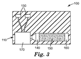
図3は、図1に示す面2に沿って切断された、図1の可搬型モニターの代替の実施形態の破断図である。この実施形態では、流体入口110に流入する気体は、流体送達装置170に流入し、デマンド物質150及び検出要素160を収めた容器140に入る。この実施形態では、気体は、この実施形態ではポンプであり、及び制御ボタン130により制御される流体送達装置170により容器に押し込まれる。
FIG. 3 is a cutaway view of an alternative embodiment of the portable monitor of FIG. 1 taken along plane 2 shown in FIG. In this embodiment, the gas flowing into the
図4は本開示の異なる代表的な可搬型モニターの斜視図を示す。図4では、可搬型モニター200は、流体入口210、リーダースクリーン220、制御ボタン230、スピーカー290、及び光295を含む。このより複雑な可搬型モニターでは、モニター対象の気体は流体入口110に入り、使用者は、様々なメッセージ及び情報を含み得る電子スクリーンである、リーダースクリーン220を観察することにより、検出要素(図示せず)をモニターしてもよい。例えば、リーダースクリーンは、モニターの状態(オン又はオフ)、使用された時間、耐用期間の終点の前に放置されていた時間などの情報を伝達することができる。制御ボタン230は、可搬型モニター100におけるなど流体送達装置を制御することができ、並びにリーダースクリーン220の関数を制御することができる。スピーカー290及び光295は、可搬型モニターと共に使用可能な任意の追加の警報装置である。スピーカーは、可搬型モニターの状態の変化又は耐用期間の終点に到達したか、又は接近しつつあるということを使用者に警告するために、音声信号又はメッセージを放送することができる。同じように、光は、可搬型モニターを点検しなければならないという使用者への追加のインジケータとして点灯又はフラッシュし始める。
FIG. 4 shows a perspective view of a different representative portable monitor of the present disclosure. In FIG. 4, the
図5は、図4に示す面5に沿って切断された、図4の可搬型モニターの1つの実施形態の破断図である。気体は気体入口210から可搬型モニターに入り、流体送達装置(ポンプ)270に入り、及びデマンド物質250及び検出要素260を含む容器240に入る。検出要素260をリーダー280によりモニターすることができる。リーダー280は、検出要素260の変化を検出するための電子リーダーである。リーダー280は、リーダースクリーン(図示しないが、図4で要素220として示す)に出力を送る。
FIG. 5 is a cutaway view of one embodiment of the portable monitor of FIG. 4 taken along
図6は、図4に示す面5に沿って切断した、図4の可搬型モニターの代替の実施形態の破断図である。上記に掲げた要素並びに追加の検出要素260b及び追加のリーダー280bは、全て存在する。追加の検出要素及びリーダーは、可搬型モニターに追加の有機蒸気を検出する能力を与え、追加の検出出力又は両方をもたらす。検出要素260bは検出要素260と同一であっても,類似であっても又は異なってもよい。同じように、検出要素260bの性状に依存して,リーダー280bは、検出要素280と同一であっても、類似であっても又は異なってもよい。
FIG. 6 is a cutaway view of an alternative embodiment of the portable monitor of FIG. 4 taken along
図7は、本開示のモニターと共の使用に好適な代表的な光学リーダー300を示す。光学式リーダー300は、少なくとも1つの光源(ここでは312及び314)、並びに少なくとも1つの検出器320を含む。1つ以上の光源(例えば312及び314)、並びに1つ以上の検出器320は、同じ支持体350上に実装されてもよい。光学リーダー300を本開示によるモニターのケースに取り付けるように構成することができる。検出要素330は、円板として示されているが、任意の好適な形状のものであってよく、及び容器(図示せず)中に収められるか又は容器からの出口流れが検出要素330にぶつかるように、配置されてもよい。少なくとも1つの光源312、314により出射される光312a、314aの少なくとも一部分は、検出要素330から反射され、少なくとも1つの検出器320により捕捉される。
FIG. 7 illustrates an exemplary
これらの実施例は単にあくまで例示を目的としたものであり、添付した特許請求の範囲に限定することを意味するものではない。 These examples are for illustrative purposes only and are not meant to be limiting on the scope of the appended claims.
(実施例1)
試験モニター管を作製して、3M Company(St.Paul,MN)から市販されている6001シリーズOVフィルターカートリッジに対する耐用期間を予測した。
Example 1
Test monitor tubes were made to predict the lifetime for a 6001 series OV filter cartridge commercially available from 3M Company (St. Paul, MN).
試験試料の作製:
デマンド物質を含む一連の試験モニター管をガラス管中で作製した。使用したデマンド物質は、Kuraray GG 12×20活性炭(6001シリーズOVカートリッジで使用したのと同一の活性炭)であった。管のデマンド物質を装填した部分の寸法は、長さ110ミリメートル及び直径9.4ミリメートルであった。
Preparation of test sample:
A series of test monitor tubes containing the demand material were made in glass tubes. The demand material used was Kuraray GG 12 × 20 activated carbon (the same activated carbon used in the 6001 series OV cartridge). The dimensions of the tube loaded with demand material were 110 millimeters long and 9.4 millimeters in diameter.
有機蒸気試験:
有機蒸気試験のために、最初に有機蒸気を含まない窒素を試料管に通して、流れを確立した。次いで、表1に示す有機蒸気流れを試料モニター管に通し、及びMIRAN Sapphire XL赤外分光計を用いて、50%破過までモニターした。破過時間を表1に示す。窒素ガスを対象の溶媒を含む冷却したインピンジャーに流すことにより、有機蒸気流れを生じさせ、引き続いて流れを追加の窒素により希釈(マスフローコントローラーにより制御)し、及びMIRAN Sapphire XL赤外分光計を用いてモニターした。最初に、分光計を使用して、入力流れの正確なppm送達を求め、次いで管出口に接続して、出口濃度を追跡した。
Organic vapor test:
For organic vapor testing, nitrogen was first passed through the sample tube without organic vapor to establish a flow. The organic vapor flow shown in Table 1 was then passed through a sample monitor tube and monitored to 50% breakthrough using a MIRAN Sapphire XL infrared spectrometer. The breakthrough time is shown in Table 1. A stream of organic vapor is generated by flowing nitrogen gas through a cooled impinger containing the solvent of interest, followed by dilution of the stream with additional nitrogen (controlled by a mass flow controller), and a MIRAN Sapphire XL infrared spectrometer. And monitored. First, a spectrometer was used to determine the accurate ppm delivery of the input stream, and then connected to the tube outlet to track the outlet concentration.
相関計算:
活性炭フィルター床に対する予期されたカートリッジ耐用期間を蒸気の内容及び濃度の関数として計算することを可能とせしめる、数学モデルがGerry Wood(Am.Ind.Hyg.Assn.J.55(1):11〜15,1994を参照のこと)により確立されている。
Correlation calculation:
A mathematical model that makes it possible to calculate the expected cartridge life for an activated carbon filter bed as a function of vapor content and concentration is Gerry Wood (Am. Ind. Hyg. Assn. J. 55 (1): 11- 15, 1994).
このモデルは、破過時間tbを、
tb=(WeW/CoQ)−(1000Weρβ/kvCo)ln[(C0−Cx)/Cx]と述べている。
式中、
Cx=出口濃度(g/L)であり、
Co=入口濃度(g/L)であり、
Q=容積流量(L/min)であり、
W=活性炭(g)の重量であり、
ρβ=活性炭床の充填密度(g/cc)であり、
We=平衡吸着容量(g/g活性炭)であり、
Kv=吸着速度係数(1/min)である。
This model uses the breakthrough time t b
t b = (W e W / C o Q) - have said (1000W e ρ β / k v C o) ln [(C 0 -C x) / C x].
Where
C x = outlet concentration (g / L),
C o = inlet concentration (g / L),
Q = volume flow rate (L / min),
W = weight of activated carbon (g),
ρ β = packing density of activated carbon bed (g / cc),
W e = equilibrium adsorption capacity (g / g activated carbon),
K v = adsorption rate coefficient (1 / min).
50%破過点は、Co=2Cxである、点として定義される。50%破過点において、ln[(C0−Cx)/Cx]項はゼロとなり、tb=(WeW/CoQ)となる。3M 6001フィルターカートリッジの予測破過時間を所定の有機蒸気濃度及び流量に対して計算することができる。これらの計算値を表2に示す。 The 50% breakthrough point is defined as the point where C o = 2C x . At the 50% breakthrough point, the ln [(C 0 −C x ) / C x ] term is zero, and t b = (W e W / C o Q). The expected breakthrough time for the 3M 6001 filter cartridge can be calculated for a given organic vapor concentration and flow rate. These calculated values are shown in Table 2.
活性炭管破過時間に(WカートリッジQ管/W管Qカートリッジ)を掛けることにより、試料カートリッジに対する実験的な破過時間を相関付けて、3M 6001フィルターカートリッジに対する50%破過時間(予測)を得た。試料モニター管の実験的な破過時間から計算されるフィルターカートリッジに対する予測破過時間も表2に示す。試料モニター管の実験的な破過時間から計算されるフィルターカートリッジに対する予測破過時間と、下式から計算されるフィルターカートリッジ破過時間との間のパーセント差異も表2に示す。
%差異=(予測時間−計算時間)/計算時間×100%
Multiply the activated carbon breakthrough time by (W Cartridge Q Tube / W Tube Q Cartridge ) to correlate the experimental breakthrough time for the sample cartridge to give a 50% breakthrough time (predicted) for the 3M 6001 filter cartridge. Obtained. Table 2 also shows the predicted breakthrough time for the filter cartridge calculated from the experimental breakthrough time of the sample monitor tube. The percent difference between the expected breakthrough time for the filter cartridge calculated from the experimental breakthrough time of the sample monitor tube and the filter cartridge breakthrough time calculated from the following equation is also shown in Table 2.
% Difference = (expected time-calculation time) / calculation time x 100%
滞留時間相関計算:
計算を行って、試験モニター管及び3M 6001シリーズOVフィルターカートリッジに対する滞留時間を求めた。試験モニター管の寸法及び3.2L/minの実験的な流量を用いて、滞留時間を0.14秒と計算した。32L/minのカートリッジ呼吸速度を仮定し、及び3M 6001カートリッジ寸法を用いて、滞留時間を0.19秒と求めた。この滞留時間によって、試験モニター管上の50%破過時間に滞留時間管に対する滞留時間カートリッジの比を掛けることにより、試験モニター管の50%破過時間(実測)から6001カートリッジに対する50%破過時間を表3に示すように予測することが可能となる。
Residence time correlation calculation:
Calculations were made to determine residence times for test monitor tubes and 3M 6001 series OV filter cartridges. Using the dimensions of the test monitor tube and an experimental flow rate of 3.2 L / min, the residence time was calculated to be 0.14 seconds. Assuming a cartridge respiration rate of 32 L / min and using 3M 6001 cartridge dimensions, the residence time was determined to be 0.19 seconds. By this residence time, the 50% breakthrough time on the test monitor tube is multiplied by the ratio of the residence time cartridge to the residence time tube to give a 50% breakthrough for the 6001 cartridge from the 50% breakthrough time (actual measurement) of the test monitor tube. The time can be predicted as shown in Table 3.

(実施例2)
試験モニター管を作製して、3M Company(St.Paul,MN)から市販されている6001シリーズOVフィルターカートリッジに対する耐用期間を予測した。
(Example 2)
Test monitor tubes were made to predict the lifetime for a 6001 series OV filter cartridge commercially available from 3M Company (St. Paul, MN).
検出フィルムの作製:
最初にベンチトップスパッタコーターを用いて厚さ127マイクロメートル(5mil)のMelinex ST 504 PET(ポリエチレンテレフタレート)フィルムの試料をAu/Pd(35mAmp、20秒)で被覆することにより、センサーフィルムを作製した。文献(Chem.Comm.,2004,pp.230〜231)で以前に述べられた方法を用いて、固有微小多孔質ポリマー(PIM)を作製した。このポリマーをテトラヒドロピラン(THP)中4重量%濃度に溶解し、Au/Pd層上に1000rpmでスピンコートした。銀ナノ粒子インキ(Cabot Labsから入手したストック溶液、バッチ457010、20.1重量%)を希釈(0.5グラムの入手したストック溶液プラス1ミリリットルのエタノール)し、PIM層上に1000rpmでスピンコートして、センサー堆積体を完成させた。次いで、多層フィルムを使用前に125℃で2時間加熱した。
Production of detection film:
A sensor film was prepared by first coating a 127 micrometer (5 mil) Melinex ST 504 PET (polyethylene terephthalate) film sample with Au / Pd (35 mAmp, 20 seconds) using a bench top sputter coater. . Intrinsic microporous polymers (PIM) were made using the methods previously described in the literature (Chem. Comm., 2004, pp. 230-231). This polymer was dissolved in tetrahydropyran (THP) at a concentration of 4% by weight and spin-coated on the Au / Pd layer at 1000 rpm. Dilute silver nanoparticle ink (stock solution obtained from Cabot Labs, batch 457010, 20.1 wt%) (0.5 grams of stock solution plus 1 milliliter of ethanol) and spin coat onto PIM layer at 1000 rpm Thus, the sensor deposit was completed. The multilayer film was then heated at 125 ° C. for 2 hours before use.
試験試料の作製:
検出フィルムを収めた試験モニター管を作製して、3M Company(St.Paul,MN)から市販されている6001シリーズOVフィルターカートリッジを模倣した。センサーフィルムを、充填前に実施例1で上述のように管の中に入れ、押し込んで、ガラス表面とできるだけきっちりと形を合わせるようにした。次いで、Kuraray GG 12×20活性炭(6001シリーズOVカートリッジで使用されている同一の活性炭)を管の中に装填した。センサーフィルム及びファイバプローブを管の入口の点から88ミリメートル(又は管の110ミリメートルの全長80%、残りの20%を活性炭容量に提供)に配置した。
Preparation of test sample:
A test monitor tube containing the detection film was made to mimic a 6001 series OV filter cartridge commercially available from 3M Company (St. Paul, MN). The sensor film was placed into the tube as described above in Example 1 and filled before being filled so that it matched the glass surface as closely as possible. Kuraray GG 12 × 20 activated carbon (the same activated carbon used in the 6001 series OV cartridge) was then loaded into the tube. The sensor film and fiber probe were placed 88 millimeters from the point of entry of the tube (or 80% of the total length of 110 millimeters of the tube, providing the remaining 20% to the activated carbon capacity).
有機蒸気試験:
MIRAN赤外分光計により管終点から出る出口ガスを分析し、Ocean Opticsファイバ光学分光計を使用して、センサーフィルムをモニターしたことを除いて、実施例1で上述したようにトルエンによる有機蒸気試験を行った(854ppm,3.2L/minの流れ)。IRで測定した50%破過時間(管の終点での)並びにセンサーフィルム応答からの50%破過時間(実測)(20%の活性炭が残る)を表4に示す。
Organic vapor test:
An organic vapor test with toluene as described above in Example 1 except that the exit gas exiting the tube end point was analyzed with a MIRAN infrared spectrometer and the sensor film was monitored using an Ocean Optics fiber optic spectrometer. (Flow of 854 ppm, 3.2 L / min). Table 4 shows the 50% breakthrough time measured at IR (at the end of the tube) as well as the 50% breakthrough time from the sensor film response (actual measurement) (20% activated carbon remains).
相関計算:
計算を上述のように行って、フィルターカートリッジに対する20%の活性炭が残った破過時間(計算)及びセンサーフィルムの実験データからの20%の活性炭が残った破過時間(予測)を得た。実施例1で上述したように計算したこれらの値を%差異と共に表4に示す。
Correlation calculation:
The calculations were performed as described above to obtain the breakthrough time (calculation) with 20% activated carbon remaining for the filter cartridge and the breakthrough time (predicted) with 20% activated carbon remaining from the sensor film experimental data. These values, calculated as described above in Example 1, are shown in Table 4 along with the% difference.
Claims (3)
モニター装置を提供する工程と、
前記モニター装置を較正して、フィルターカートリッジの耐用期間に対応する工程とを含み、
前記モニター装置が、
容器内のデマンド物質であり、有機蒸気を吸収する能力がある該デマンド物質、
検出点を有する検出要素、
前記検出要素用のリーダー、及び
流体送達パラメーターを含む流体送達装置、を含み、
前記流体送達パラメーター及び前記検出要素の前記検出点が
前記フィルターカートリッジの耐用期間に相関付けられ、
前記モニター装置を較正して、前記フィルターカートリッジの耐用期間に対応する工程が、
前記フィルターカートリッジに対する滞留時間を決定する工程と、
前記モニター装置に対する滞留時間を決定する工程と、
前記モニター装置の滞留時間と、前記フィルターカートリッジの滞留時間との比を決定する工程と、
前記比を使用して、前記検出要素の前記検出点の応答を前記フィルターカートリッジの耐用期間に相関付ける工程とを含む、方法。 A method for correlating a monitoring device with a useful life of a filter cartridge,
Providing a monitor apparatus,
By calibrating the monitoring device, and a step corresponding to the useful life of the full I Luther cartridge,
The monitoring device is
A demand substance in a container, the demand substance capable of absorbing organic vapor ,
A detection element having a detection point,
A reader for the sensing element and a fluid delivery device comprising fluid delivery parameters;
The fluid delivery parameter and the detection point of the detection element are correlated to the lifetime of the filter cartridge ;
Calibrating the monitoring device to correspond to the lifetime of the filter cartridge,
Determining a residence time for the filter cartridge;
Determining a residence time for the monitoring device;
Determining a ratio between the residence time of the monitoring device and the residence time of the filter cartridge;
Correlating the response of the detection point of the detection element to the lifetime of the filter cartridge using the ratio .
tSL=tb(WカートリッジQモニター/WモニターQカートリッジ)
により記述され、式中、
tSLが前記フィルターカートリッジの耐用期間であり、
tbが前記モニター装置の耐用期間であり、
Wカートリッジが前記フィルターカートリッジ内の前記デマンド物質の重量であり、
Qモニターが前記モニター装置内の流量であり、
Wモニターが前記モニター装置内の前記デマンド物質の重量であり、
Qカートリッジが前記フィルターカートリッジ内の流量である、請求項2に記載の方法。 The service life of the filter cartridge is expressed by the formula:
t SL = t b (W cartridge Q monitor / W monitor Q cartridge )
Where
t SL is the lifetime of the filter cartridge;
t b is the lifetime of the monitoring device ;
W cartridge is the weight of the demand material in the filter cartridge;
Q monitor is the flow rate in the monitoring device ,
W monitor is the weight of the demand material in the monitoring device ;
The method of claim 2 , wherein the Q cartridge is a flow rate in the filter cartridge.
Applications Claiming Priority (3)
| Application Number | Priority Date | Filing Date | Title |
|---|---|---|---|
| US38865910P | 2010-10-01 | 2010-10-01 | |
| US61/388,659 | 2010-10-01 | ||
| PCT/US2011/049828 WO2012044430A2 (en) | 2010-10-01 | 2011-08-31 | Method for correlating a monitoring device to the end of service life of a filter cartridge |
Publications (3)
| Publication Number | Publication Date |
|---|---|
| JP2013545076A JP2013545076A (en) | 2013-12-19 |
| JP2013545076A5 JP2013545076A5 (en) | 2014-10-16 |
| JP5868408B2 true JP5868408B2 (en) | 2016-02-24 |
Family
ID=45893729
Family Applications (1)
| Application Number | Title | Priority Date | Filing Date |
|---|---|---|---|
| JP2013531602A Expired - Fee Related JP5868408B2 (en) | 2010-10-01 | 2011-08-31 | Method for correlating a monitoring device to the end of life of a filter cartridge |
Country Status (8)
| Country | Link |
|---|---|
| US (1) | US9291484B2 (en) |
| EP (1) | EP2622322B1 (en) |
| JP (1) | JP5868408B2 (en) |
| KR (1) | KR20130118874A (en) |
| CN (1) | CN103140749B (en) |
| BR (1) | BR112013007517A2 (en) |
| PL (1) | PL2622322T3 (en) |
| WO (1) | WO2012044430A2 (en) |
Families Citing this family (10)
| Publication number | Priority date | Publication date | Assignee | Title |
|---|---|---|---|---|
| KR20130118874A (en) | 2010-10-01 | 2013-10-30 | 쓰리엠 이노베이티브 프로퍼티즈 컴파니 | Method for correlating a monitoring device to the end of service life of a filter cartridge |
| BR112013007516A2 (en) | 2010-10-01 | 2020-10-06 | 3M Innovative Properties Company | portable monitor for end of life indication |
| CN109381812A (en) * | 2017-08-08 | 2019-02-26 | 研能科技股份有限公司 | Air filtration protector |
| TWI650154B (en) | 2017-08-08 | 2019-02-11 | 研能科技股份有限公司 | Air-filtering protector |
| TWI684730B (en) * | 2017-08-08 | 2020-02-11 | 研能科技股份有限公司 | Driving and information-transmission system of air-filtering protector |
| US10958991B2 (en) | 2017-09-15 | 2021-03-23 | Mann+Hummel Gmbh | Filter element sensor module having processing and wireless communication capabilities |
| CN108211654B (en) * | 2018-01-07 | 2021-01-26 | 境卫士(重庆)环保科技有限公司 | Flue gas treatment environmental protection system with flow control and automatic core changing function |
| US10953369B2 (en) | 2018-03-08 | 2021-03-23 | Georgia Tech Research Corporation | Spirocentric compounds and polymers thereof |
| CN110927149A (en) * | 2019-11-28 | 2020-03-27 | 中冶建筑研究总院有限公司 | Device and method for testing protection time of civil air defense special catalyst DMMP |
| WO2023100145A1 (en) | 2021-12-03 | 2023-06-08 | 3M Innovative Properties Company | Systems and methods for adsorption capacity estimation |
Family Cites Families (39)
| Publication number | Priority date | Publication date | Assignee | Title |
|---|---|---|---|---|
| US3971373A (en) | 1974-01-21 | 1976-07-27 | Minnesota Mining And Manufacturing Company | Particle-loaded microfiber sheet product and respirators made therefrom |
| US4135896A (en) | 1975-12-11 | 1979-01-23 | Cvi Corporation | Gas purifier having rechargeable adsorber filter with removeable rechargeable sample canister |
| US4208194A (en) | 1977-09-26 | 1980-06-17 | Minnesota Mining And Manufacturing Company | Monitoring device |
| US4237726A (en) * | 1979-08-01 | 1980-12-09 | The Dow Chemical Company | Process for predicting the useful life of a respirator cartridge |
| US4552570A (en) * | 1980-05-02 | 1985-11-12 | Pall Corporation | Adsorbent fractionator with automatic cycle control and process |
| US4326514A (en) | 1980-06-20 | 1982-04-27 | Minnesota Mining And Manufacturing Company | Cartridge respirator with service life indicator |
| US4421719A (en) * | 1980-06-20 | 1983-12-20 | Minnesota Mining And Manufacturing Company | Colorimetric indicators |
| US4948639A (en) | 1986-07-31 | 1990-08-14 | Kimberly-Clark Corporation | Vacuum cleaner bag |
| JPH01156730A (en) | 1987-12-15 | 1989-06-20 | Fuji Photo Film Co Ltd | Scanning optical device |
| JPH01156730U (en) * | 1988-04-15 | 1989-10-27 | ||
| US5976467A (en) | 1997-07-11 | 1999-11-02 | Donaldson Company, Inc. | Airborne contaminant indicator |
| US6187596B1 (en) | 1997-07-11 | 2001-02-13 | Donaldson Company, Inc. | Airborne contaminant indicator |
| US5858457A (en) | 1997-09-25 | 1999-01-12 | Sandia Corporation | Process to form mesostructured films |
| US6312793B1 (en) | 1999-05-26 | 2001-11-06 | International Business Machines Corporation | Multiphase low dielectric constant material |
| US6573305B1 (en) | 1999-09-17 | 2003-06-03 | 3M Innovative Properties Company | Foams made by photopolymerization of emulsions |
| US6497756B1 (en) * | 2000-09-12 | 2002-12-24 | North Safety Products, Inc. | Service life indicator for respirator cartridge |
| GB0210296D0 (en) * | 2002-05-04 | 2002-06-12 | Reckitt Benckiser Uk Ltd | Device |
| US7449146B2 (en) | 2002-09-30 | 2008-11-11 | 3M Innovative Properties Company | Colorimetric sensor |
| GB0317557D0 (en) | 2003-07-26 | 2003-08-27 | Univ Manchester | Microporous polymer material |
| DE10356776B4 (en) * | 2003-12-02 | 2011-04-14 | BLüCHER GMBH | Plasma-treated adsorption filter material with protection against chemical toxins, its use and protective materials comprising this adsorption filter material |
| US7201036B2 (en) | 2004-02-27 | 2007-04-10 | Hunter Manufacturing Co. | Residual life indicating system |
| US20050276721A1 (en) | 2004-05-25 | 2005-12-15 | Steris Inc. | Method and apparatus for controlling the concentration of a sterilant chemical in a fluid |
| US7442237B1 (en) * | 2004-09-16 | 2008-10-28 | The United States Of America As Represented By The Secretary Of The Army | Multi-agent end-of-service-life indicator for respirator filters |
| US20060096911A1 (en) | 2004-11-08 | 2006-05-11 | Brey Larry A | Particle-containing fibrous web |
| CN101189059B (en) * | 2005-07-04 | 2011-06-15 | 三菱电机株式会社 | Apparatus for volatile organic compound treatment |
| US8293340B2 (en) | 2005-12-21 | 2012-10-23 | 3M Innovative Properties Company | Plasma deposited microporous analyte detection layer |
| US7556774B2 (en) | 2005-12-21 | 2009-07-07 | 3M Innovative Properties Company | Optochemical sensor and method of making the same |
| JP4918259B2 (en) * | 2006-01-06 | 2012-04-18 | 株式会社キャタラー | Low molecular organic gas absorbent and fuel vapor processing apparatus using the same |
| US7744684B2 (en) * | 2006-04-26 | 2010-06-29 | Chromatography Research Supplies, Inc. | High capacity gas filter system with indicator |
| US9120043B2 (en) * | 2006-05-30 | 2015-09-01 | 3M Innovative Properties Company | Filter sensor |
| US7906223B2 (en) | 2006-09-11 | 2011-03-15 | 3M Innovative Properties Company | Permeable nanoparticle reflector |
| US8067110B2 (en) | 2006-09-11 | 2011-11-29 | 3M Innovative Properties Company | Organic vapor sorbent protective device with thin-film indicator |
| ITPD20070240A1 (en) * | 2007-07-16 | 2009-01-17 | Laica Spa | METHOD OF DETERMINING THE CONDITIONS OF EXHAUSTATION OF THE FILTERING CARTRIDGE IN A WATER OR SIMILAR EQUIPMENT AND OPERATING SYSTEM ACCORDING TO THIS METHOD. |
| US7749303B2 (en) * | 2007-08-30 | 2010-07-06 | The Boeing Company | Service life indicator for chemical filters |
| BRPI0915883A2 (en) | 2008-07-10 | 2015-11-03 | Water Security Corp | iodinated resin filter and filter life indicator |
| CN102439422B (en) | 2009-03-30 | 2016-05-18 | 3M创新有限公司 | For detection of photoelectric method and the device of analyte |
| US8955515B2 (en) | 2009-10-23 | 2015-02-17 | 3M Innovative Properties Company | Patterned chemical sensor having inert occluding layer |
| US8821621B2 (en) | 2010-04-02 | 2014-09-02 | 3M Innovative Properties Company | Filter systems including optical analyte sensors and optical readers |
| KR20130118874A (en) | 2010-10-01 | 2013-10-30 | 쓰리엠 이노베이티브 프로퍼티즈 컴파니 | Method for correlating a monitoring device to the end of service life of a filter cartridge |
-
2011
- 2011-08-31 KR KR1020137010689A patent/KR20130118874A/en active IP Right Grant
- 2011-08-31 EP EP11829736.5A patent/EP2622322B1/en not_active Not-in-force
- 2011-08-31 PL PL11829736T patent/PL2622322T3/en unknown
- 2011-08-31 US US13/876,402 patent/US9291484B2/en active Active
- 2011-08-31 JP JP2013531602A patent/JP5868408B2/en not_active Expired - Fee Related
- 2011-08-31 WO PCT/US2011/049828 patent/WO2012044430A2/en active Application Filing
- 2011-08-31 BR BR112013007517-1A patent/BR112013007517A2/en not_active Application Discontinuation
- 2011-08-31 CN CN201180047238.4A patent/CN103140749B/en not_active Expired - Fee Related
Also Published As
| Publication number | Publication date |
|---|---|
| EP2622322A2 (en) | 2013-08-07 |
| BR112013007517A2 (en) | 2020-09-01 |
| WO2012044430A3 (en) | 2012-06-21 |
| CN103140749A (en) | 2013-06-05 |
| CN103140749B (en) | 2016-03-30 |
| WO2012044430A2 (en) | 2012-04-05 |
| US9291484B2 (en) | 2016-03-22 |
| PL2622322T3 (en) | 2018-09-28 |
| KR20130118874A (en) | 2013-10-30 |
| JP2013545076A (en) | 2013-12-19 |
| EP2622322B1 (en) | 2018-04-25 |
| EP2622322A4 (en) | 2014-03-19 |
| US20130263640A1 (en) | 2013-10-10 |
Similar Documents
| Publication | Publication Date | Title |
|---|---|---|
| JP6045496B2 (en) | Portable monitor for end of life display | |
| JP5868408B2 (en) | Method for correlating a monitoring device to the end of life of a filter cartridge | |
| JP5832514B2 (en) | Filter system including a patterned optical analyte sensor and an optical reader | |
| JP6071873B2 (en) | Alignment alignment mechanism for specimen sensor optical reader | |
| RU2537093C2 (en) | Filter system including structured optical sensors of analytes and optical readers | |
| AU2007297046B2 (en) | Organic vapor sorbent protective device with thin film indicator | |
| RU2490615C2 (en) | Multilayer arrays of colour sensors |
Legal Events
| Date | Code | Title | Description |
|---|---|---|---|
| A521 | Written amendment |
Free format text: JAPANESE INTERMEDIATE CODE: A523 Effective date: 20140901 |
|
| A621 | Written request for application examination |
Free format text: JAPANESE INTERMEDIATE CODE: A621 Effective date: 20140901 |
|
| A977 | Report on retrieval |
Free format text: JAPANESE INTERMEDIATE CODE: A971007 Effective date: 20150527 |
|
| A131 | Notification of reasons for refusal |
Free format text: JAPANESE INTERMEDIATE CODE: A131 Effective date: 20150707 |
|
| A521 | Written amendment |
Free format text: JAPANESE INTERMEDIATE CODE: A523 Effective date: 20151005 |
|
| TRDD | Decision of grant or rejection written | ||
| A01 | Written decision to grant a patent or to grant a registration (utility model) |
Free format text: JAPANESE INTERMEDIATE CODE: A01 Effective date: 20151208 |
|
| A61 | First payment of annual fees (during grant procedure) |
Free format text: JAPANESE INTERMEDIATE CODE: A61 Effective date: 20160105 |
|
| R150 | Certificate of patent or registration of utility model |
Ref document number: 5868408 Country of ref document: JP Free format text: JAPANESE INTERMEDIATE CODE: R150 |
|
| LAPS | Cancellation because of no payment of annual fees |